Embed Size (px)
Citation preview

Product Version
Document Organization
Getting Help
FASTFIND LINKS
Contents
Hitachi Virtual Storage PlatformUser and Reference Guide
MK-90RD7042-11

Hitachi VSP User and Reference Guide
ii
©2010-2013 Hitachi Data Systems Ltd, All rights reserved.
No part of this publication may be reproduced or transmitted in any form or by any means, electronic or mechanical, including photocopying and recording, or stored in a database or retrieval system for any purpose without the express written permission of Hitachi, Ltd. (hereinafter referred to as "Hitachi"), and Hitachi Data Systems Corporation (hereinafter referred to as "Hitachi Data Systems").
Hitachi and Hitachi Data Systems reserve the right to make changes to this document at any time without notice and assume no responsibility for its use. This document contains the most current information available at the time of publication. When new or revised information becomes available, this entire document will be updated and distributed to all registered users.
Some of the features described in this document may not be currently available. Refer to the most recent product announcement or contact your local Hitachi Data Systems sales office for information about feature and product availability.
Notice: Hitachi Data Systems products and services can be ordered only under the terms and conditions of Hitachi Data Systems' applicable agreements. The use of Hitachi Data Systems products is governed by the terms of your agreements with Hitachi Data Systems.
Hitachi is a registered trademark of Hitachi, Ltd., in the United States and other countries. Hitachi Data Systems is a registered trademark and service mark of Hitachi in the United States and other countries.
ShadowImage and TrueCopy are registered trademarks of Hitachi Data Systems.
AIX, FICON, FlashCopy, IBM, MVS/ESA, MVS/XA, OS/390, S/390, VM/ESA, VSE/ESA, z/OS, zSeries, z/VM, and zVSE are registered trademarks or trademarks of International Business Machines Corporation.
All other trademarks, service marks, and company names are properties of their respective owners.
Microsoft product screen shots reprinted with permission from Microsoft Corporation

Contents iiiHitachi VSP User and Reference Guide
Contents
Preface . . . . . . . . . . . . . . . . . . . . . . . . . . . . . . . . . . . . . . . . . . . viiSafety and environmental information . . . . . . . . . . . . . . . . . . . . . . . . . . . . . . .viiiIntended audience. . . . . . . . . . . . . . . . . . . . . . . . . . . . . . . . . . . . . . . . . . . . .viiiProduct version . . . . . . . . . . . . . . . . . . . . . . . . . . . . . . . . . . . . . . . . . . . . . . .viiiDocument revision level . . . . . . . . . . . . . . . . . . . . . . . . . . . . . . . . . . . . . . . . .viiiChanges in this revision . . . . . . . . . . . . . . . . . . . . . . . . . . . . . . . . . . . . . . . . . ixReferenced documents. . . . . . . . . . . . . . . . . . . . . . . . . . . . . . . . . . . . . . . . . . ixDocument organization . . . . . . . . . . . . . . . . . . . . . . . . . . . . . . . . . . . . . . . . . ixDocument conventions. . . . . . . . . . . . . . . . . . . . . . . . . . . . . . . . . . . . . . . . . . . xConvention for storage capacity values . . . . . . . . . . . . . . . . . . . . . . . . . . . . . . xiAccessing product documentation . . . . . . . . . . . . . . . . . . . . . . . . . . . . . . . . . . xiGetting help . . . . . . . . . . . . . . . . . . . . . . . . . . . . . . . . . . . . . . . . . . . . . . . . . xiComments . . . . . . . . . . . . . . . . . . . . . . . . . . . . . . . . . . . . . . . . . . . . . . . . . . xi
1 Introduction . . . . . . . . . . . . . . . . . . . . . . . . . . . . . . . . . . . . . . . 1-1Hitachi Virtual Storage Platform overview. . . . . . . . . . . . . . . . . . . . . . . . . . . . 1-2Hardware overview . . . . . . . . . . . . . . . . . . . . . . . . . . . . . . . . . . . . . . . . . . . 1-2
Controller chassis . . . . . . . . . . . . . . . . . . . . . . . . . . . . . . . . . . . . . . . . . 1-4Drive Chassis . . . . . . . . . . . . . . . . . . . . . . . . . . . . . . . . . . . . . . . . . . . . 1-5Flash chassis . . . . . . . . . . . . . . . . . . . . . . . . . . . . . . . . . . . . . . . . . . . . . 1-5
Features . . . . . . . . . . . . . . . . . . . . . . . . . . . . . . . . . . . . . . . . . . . . . . . . . . . 1-6Scalability . . . . . . . . . . . . . . . . . . . . . . . . . . . . . . . . . . . . . . . . . . . . . . . 1-6High performance . . . . . . . . . . . . . . . . . . . . . . . . . . . . . . . . . . . . . . . . . 1-7High capacity . . . . . . . . . . . . . . . . . . . . . . . . . . . . . . . . . . . . . . . . . . . . 1-8Connectivity . . . . . . . . . . . . . . . . . . . . . . . . . . . . . . . . . . . . . . . . . . . . . 1-8
Virtual Storage Platform . . . . . . . . . . . . . . . . . . . . . . . . . . . . . . . . . . . 1-8Storage Navigator . . . . . . . . . . . . . . . . . . . . . . . . . . . . . . . . . . . . . . . 1-8
High reliability . . . . . . . . . . . . . . . . . . . . . . . . . . . . . . . . . . . . . . . . . . . . 1-8Non-disruptive service and upgrades . . . . . . . . . . . . . . . . . . . . . . . . . . . . 1-9Economical and quiet . . . . . . . . . . . . . . . . . . . . . . . . . . . . . . . . . . . . . . . 1-9
Specifications . . . . . . . . . . . . . . . . . . . . . . . . . . . . . . . . . . . . . . . . . . . . . . . 1-9System capacities with flash modules . . . . . . . . . . . . . . . . . . . . . . . . . . 1-11
Software features and functions . . . . . . . . . . . . . . . . . . . . . . . . . . . . . . . . . 1-12

Hitachi VSP User and Reference Guide
iv Contents
2 Functional and Operational Characteristics . . . . . . . . . . . . . . . . . . 2-1System architecture overview . . . . . . . . . . . . . . . . . . . . . . . . . . . . . . . . . . . . 2-2Hardware architecture . . . . . . . . . . . . . . . . . . . . . . . . . . . . . . . . . . . . . . . . . 2-2RAID implementation overview. . . . . . . . . . . . . . . . . . . . . . . . . . . . . . . . . . . 2-2
Array groups and RAID levels . . . . . . . . . . . . . . . . . . . . . . . . . . . . . . . . . 2-3Sequential data striping . . . . . . . . . . . . . . . . . . . . . . . . . . . . . . . . . . . . . 2-5LDEV striping across array groups . . . . . . . . . . . . . . . . . . . . . . . . . . . . . . 2-5
CU images, LVIs, and logical units. . . . . . . . . . . . . . . . . . . . . . . . . . . . . . . . . 2-6CU images . . . . . . . . . . . . . . . . . . . . . . . . . . . . . . . . . . . . . . . . . . . . . . 2-6Logical volume images. . . . . . . . . . . . . . . . . . . . . . . . . . . . . . . . . . . . . . 2-6Logical units . . . . . . . . . . . . . . . . . . . . . . . . . . . . . . . . . . . . . . . . . . . . . 2-7
Mainframe operations . . . . . . . . . . . . . . . . . . . . . . . . . . . . . . . . . . . . . . . . . 2-7Mainframe compatibility and functionality . . . . . . . . . . . . . . . . . . . . . . . . 2-7Mainframe operating system support. . . . . . . . . . . . . . . . . . . . . . . . . . . . 2-8Mainframe configuration . . . . . . . . . . . . . . . . . . . . . . . . . . . . . . . . . . . . 2-8
System option modes, host modes, and host mode options. . . . . . . . . . . . . . . 2-8System option modes . . . . . . . . . . . . . . . . . . . . . . . . . . . . . . . . . . . . . . 2-8Host Modes and host mode options. . . . . . . . . . . . . . . . . . . . . . . . . . . . 2-55
Open-systems operations. . . . . . . . . . . . . . . . . . . . . . . . . . . . . . . . . . . . . . 2-55Open-systems compatibility and functionality . . . . . . . . . . . . . . . . . . . . . 2-55Open-systems host platform support . . . . . . . . . . . . . . . . . . . . . . . . . . . 2-55Open systems configuration . . . . . . . . . . . . . . . . . . . . . . . . . . . . . . . . . 2-56
Storage Navigator . . . . . . . . . . . . . . . . . . . . . . . . . . . . . . . . . . . . . . . . . . . 2-56
3 System Components . . . . . . . . . . . . . . . . . . . . . . . . . . . . . . . . . . 3-1Controller chassis . . . . . . . . . . . . . . . . . . . . . . . . . . . . . . . . . . . . . . . . . . . . 3-2System control panel . . . . . . . . . . . . . . . . . . . . . . . . . . . . . . . . . . . . . . . . . . 3-5Drive chassis. . . . . . . . . . . . . . . . . . . . . . . . . . . . . . . . . . . . . . . . . . . . . . . . 3-5Flash components . . . . . . . . . . . . . . . . . . . . . . . . . . . . . . . . . . . . . . . . . . . . 3-8
Flash module . . . . . . . . . . . . . . . . . . . . . . . . . . . . . . . . . . . . . . . . . . . . 3-8Flash box . . . . . . . . . . . . . . . . . . . . . . . . . . . . . . . . . . . . . . . . . . . . . . . 3-9Flash chassis. . . . . . . . . . . . . . . . . . . . . . . . . . . . . . . . . . . . . . . . . . . . 3-10Flash configurations. . . . . . . . . . . . . . . . . . . . . . . . . . . . . . . . . . . . . . . 3-11Flash RAID configurations . . . . . . . . . . . . . . . . . . . . . . . . . . . . . . . . . . 3-12
Cache memory . . . . . . . . . . . . . . . . . . . . . . . . . . . . . . . . . . . . . . . . . . . . . 3-13Memory operation . . . . . . . . . . . . . . . . . . . . . . . . . . . . . . . . . . . . . . . . 3-14Data Protection . . . . . . . . . . . . . . . . . . . . . . . . . . . . . . . . . . . . . . . . . . 3-14
Shared memory . . . . . . . . . . . . . . . . . . . . . . . . . . . . . . . . . . . . . . . . . . . . 3-14
4 Power On/Off Procedures . . . . . . . . . . . . . . . . . . . . . . . . . . . . . . 4-1Safety and environmental information . . . . . . . . . . . . . . . . . . . . . . . . . . . . . . 4-2Standby mode . . . . . . . . . . . . . . . . . . . . . . . . . . . . . . . . . . . . . . . . . . . . . . 4-2Normal Power On/Off procedures . . . . . . . . . . . . . . . . . . . . . . . . . . . . . . . . . 4-3
Power On procedures . . . . . . . . . . . . . . . . . . . . . . . . . . . . . . . . . . . . . . 4-3Power Off procedures . . . . . . . . . . . . . . . . . . . . . . . . . . . . . . . . . . . . . . 4-4

Contents vHitachi VSP User and Reference Guide
Emergency power off/on procedure. . . . . . . . . . . . . . . . . . . . . . . . . . . . . . . . 4-4Emergency power off procedure . . . . . . . . . . . . . . . . . . . . . . . . . . . . . . . 4-4Power on procedure after emergency power off . . . . . . . . . . . . . . . . . . . . 4-5
Battery backup operations . . . . . . . . . . . . . . . . . . . . . . . . . . . . . . . . . . . . . . 4-5Cache destage batteries . . . . . . . . . . . . . . . . . . . . . . . . . . . . . . . . . . . . . 4-6
Battery life . . . . . . . . . . . . . . . . . . . . . . . . . . . . . . . . . . . . . . . . . . . . 4-6Long Term Array Storage . . . . . . . . . . . . . . . . . . . . . . . . . . . . . . . . . . . . 4-6
5 Troubleshooting . . . . . . . . . . . . . . . . . . . . . . . . . . . . . . . . . . . . . 5-1Getting help . . . . . . . . . . . . . . . . . . . . . . . . . . . . . . . . . . . . . . . . . . . . . . . . 5-2Solving problems. . . . . . . . . . . . . . . . . . . . . . . . . . . . . . . . . . . . . . . . . . . . . 5-2Service Information Messages . . . . . . . . . . . . . . . . . . . . . . . . . . . . . . . . . . . 5-2
A Specifications . . . . . . . . . . . . . . . . . . . . . . . . . . . . . . . . . . . . . . A-1Mechanical specifications . . . . . . . . . . . . . . . . . . . . . . . . . . . . . . . . . . . . . . . A-2Electrical specifications. . . . . . . . . . . . . . . . . . . . . . . . . . . . . . . . . . . . . . . . . A-2Environmental specifications. . . . . . . . . . . . . . . . . . . . . . . . . . . . . . . . . . . . . A-6Equipment noise . . . . . . . . . . . . . . . . . . . . . . . . . . . . . . . . . . . . . . . . . . . . . A-7Heat output and air flow . . . . . . . . . . . . . . . . . . . . . . . . . . . . . . . . . . . . . . . A-7PDU specifications . . . . . . . . . . . . . . . . . . . . . . . . . . . . . . . . . . . . . . . . . . . . A-8
B Comparing Universal Storage Platform V/VM and Virtual Storage Platform B-1
Comparison of USP V/VM and VSP . . . . . . . . . . . . . . . . . . . . . . . . . . . . . . . . B-2
C Regulatory Compliance. . . . . . . . . . . . . . . . . . . . . . . . . . . . . . . . C-1Regulatory compliance . . . . . . . . . . . . . . . . . . . . . . . . . . . . . . . . . . . . . . . . . C-2US FCC Notice. . . . . . . . . . . . . . . . . . . . . . . . . . . . . . . . . . . . . . . . . . . . . . . C-4
Electronic emissions testing . . . . . . . . . . . . . . . . . . . . . . . . . . . . . . . . . . C-4European Declaration of Conformity . . . . . . . . . . . . . . . . . . . . . . . . . . . . . . . C-4Notice of export controls . . . . . . . . . . . . . . . . . . . . . . . . . . . . . . . . . . . . . . . C-5Hazardous and toxic substances . . . . . . . . . . . . . . . . . . . . . . . . . . . . . . . . . . C-5Disposal . . . . . . . . . . . . . . . . . . . . . . . . . . . . . . . . . . . . . . . . . . . . . . . . . . . C-5Recycling . . . . . . . . . . . . . . . . . . . . . . . . . . . . . . . . . . . . . . . . . . . . . . . . . . C-6Electronic emissions certificates . . . . . . . . . . . . . . . . . . . . . . . . . . . . . . . . . . C-6

Hitachi VSP User and Reference Guide
vi Contents

Preface viiHitachi VSP User and Reference Guide
Preface
This manual provides instructions and information to use the Hitachi Virtual Storage Platform storage system.
Read this document carefully to understand how to use this product, and keep a copy for reference.
This preface includes the following information:
□ Safety and environmental information
□ Intended audience
□ Product version
□ Document revision level
□ Changes in this revision
□ Referenced documents
□ Document organization
□ Document conventions
□ Convention for storage capacity values
□ Accessing product documentation
□ Getting help
□ Comments

Hitachi VSP User and Reference Guide
viii Preface
Safety and environmental information
Intended audienceThis document is intended for system administrators, Hitachi Data Systems representatives, and authorized service providers who are involved in installing, configuring, and operating the Hitachi Virtual Storage Platform.
Readers of this document should have at least the following knowledge and experience:
• A background in data processing and an understanding of RAID storagesystems and their basic functions.
• Familiarity with the Hitachi Virtual Storage Platform, the StorageNavigator software that runs on it, and the Hitachi Storage NavigatorUser Guide.
• Familiarity with the operating system and web browser software on thesystem hosting the Storage Navigator software.
Product versionThis document revision applies to Hitachi Virtual Storage Platform firmware version 70-06-0x and later.
Document revision level
Caution: Before operating or working on the Virtual Storage Platform, read the safety and environmental information in Regulatory Compliance on page C-1.
Revision Date Description
MK-90RD7042-00 August 2010 Initial release
MK-90RD7042-01 November 2010 Supersedes and replaces MK-90RD7042-00
MK-90RD7042-02 December 2010 Supersedes and replaces MK-90RD7042-01
MK-90RD7042-03 April 2011 Supersedes and replaces MK-90RD7042-02
MK-90RD7042-04 August 2011 Supersedes and replaces MK-90RD7042-03
MK-90RD7042-05 November 2011 Supersedes and replaces MK-90RD7042-04
MK-90RD7042-06 February 2012 Supersedes and replaces MK-90RD7042-05
MK-90RD7042-07 June 2012 Supersedes and replaces MK-90RD7042-06
MK-90RD7042-08 November 2012 Supersedes and replaces MK-90RD7042-07
MK-90RD7042-09 November 2012 Supersedes and replaces MK-90RD7042-08
MK-90RD7042-10 July 2013 Supersedes and replaces MK-90RD7042-09
MK-90RD7042-11 August 2013 Supersedes and replaces MK-90RD7042-10

Preface ixHitachi VSP User and Reference Guide
Changes in this revisionThe following items are changed in this revision of the manual:
• Updated SOM 900 information.
• Removed 3-1/2 in. 400 GB SSD drive from Chapter 1 and Chapter 3.
• Added the 3.2 GB flash module to Chapters 1 and 3. Updated theenvironmental specifications table with flash module information.
Referenced documentsHitachi Virtual Storage Platform documentation:
• Hitachi Storage Navigator User Guide, MK-90RD7027
• Hitachi Virtual Storage Platform Documentation Roadmap, MK-90RD7039
• Hitachi Virtual Storage Platform Installation Planning Guide, MK-90RD7041
Document organizationThe following table provides an overview of the contents and organization of this document. Click the chapter title in the left column to go to that chapter. The first page of each chapter provides links to the sections in that chapter.
Chapter/Appendix Description
Chapter 1, Introduction This chapter provides an overview of the Virtual Storage Platform hardware and software.
Chapter 2, Functional and Operational Characteristics
This chapter provides a brief description of the Virtual Storage Platform architecture.
Chapter 3, System Components
This chapter provides a more detailed description of the hardware than chapter 1.
Chapter 4, Power On/Off Procedures
This chapter describes the procedures to power the Virtual Storage Platform storage system on and off, and also provides information about the battery backup for the cache memory.
Chapter 5, Troubleshooting This chapter provides basic troubleshooting information for the Virtual Storage Platform storage system.
Appendix A, Specifications This appendix proves the mechanical, electrical, environmental, and other specifications for the Virtual Storage Platform storage system.
Appendix B, Comparing Universal Storage Platform V/VM and Virtual Storage Platform
This appendix describes the differences between the Virtual Storage Platform and the Universal Storage Platform V/VM.
Appendix C, Regulatory Compliance
This appendix describes the regulatory laws and requirements that the Virtual Storage Platform adheres to.
Glossary Defines the special terms used in this document.
Index Lists important topics in this document in alphabetical order.

Hitachi VSP User and Reference Guide
x Preface
Document conventionsThis document uses the following typographic conventions:
This document uses the following icons to draw attention to information:
Convention Description
Bold Indicates text on a window, other than the window title, including menus, menu options, buttons, fields, and labels. Example: Click OK.
Italic Indicates a variable, which is a placeholder for actual text provided by the user or system. Example: copy source-file target-file
Note: Angled brackets (< >) are also used to indicate variables.
screen/code Indicates text that is displayed on screen or entered by the user. Example: # pairdisplay -g oradb
< > angled brackets Indicates a variable, which is a placeholder for actual text provided by the user or system. Example: # pairdisplay -g <group>
Note: Italic font is also used to indicate variables.
[ ] square brackets Indicates optional values. Example: [ a | b ] indicates that you can choose a, b, or nothing.
{ } braces Indicates required or expected values. Example: { a | b } indicates that you must choose either a or b.
| vertical bar Indicates that you have a choice between two or more options or arguments. Examples:
[ a | b ] indicates that you can choose a, b, or nothing.
{ a | b } indicates that you must choose either a or b.
Icon Meaning Description
Tip Tips provide helpful information, guidelines, or suggestions for performing tasks more effectively.
Note Notes emphasize or supplement important points of the main text.
Caution Cautions indicate that failure to take a specified action could result in damage to the software or hardware.
WARNING Warnings indicate that failure to tae a specified action could result in loss of data or serious damage to hardware.
ELECTRIC SHOCK HAZARD
Failure to take appropriate precautions such as not opening or touching hazardous areas of the equipment could result in injury or death.

Preface xiHitachi VSP User and Reference Guide
Convention for storage capacity valuesPhysical and logical storage capacities of disk drives in Hitachi Data Systems storage products are calculated based on the following values:
Logical storage capacity values (logical device capacity) are calculated based on the following values:
Accessing product documentationThe VSP user documentation is available on the Hitachi Data Systems Support Portal: https://Portal.HDS.com. Check this site for the most current documentation, including important updates that may have been made after the release of the product.
Getting helpThe Hitachi Data Systems customer support staff is available 24 hours a day, seven days a week. If you need technical support, log on to the Hitachi Data Systems support portal for contact information: https://Portal.HDS.com
CommentsPlease send us your comments on this document: [email protected]. Include the document title, number, and revision. Please refer to specific sections and paragraphs whenever possible.
Thank you! (All comments become the property of Hitachi Data Systems.)
Logical Units: Block Size - 512 Bytes (Logical Disk Capacity)
1 KB (kilobyte) = 1,024 bytes (210) 1 TB (terabyte) = 1,0244 bytes
1 MB (megabyte) = 1,0242 bytes 1 PB (petabyte) = 1,0245 bytes
1 GB (gigabyte) = 1,0243 bytes 1 EB (exabyte) = 1,0246 bytes
Hard Disk Drives (HDDs) (Physical Disk Capacity)
1 KB = 1,000 bytes 1 TB = 1,0004 bytes
1 MB = 1,0002 bytes 1 PB = 1,0005 bytes
1 GB = 1,0003 bytes 1 EB = 1,0006 bytes

Hitachi VSP User and Reference Guide
xii Preface

1
Introduction 1–1Hitachi VSP User and Reference Guide
Introduction
This chapter provides a brief description of the hardware and software used in the Hitachi Virtual Storage Platform storage system. Detailed information is located in Chapter 2, Functional and Operational Characteristics on page 2-1, and Chapter 3, System Components on page 3-1.
□ Hitachi Virtual Storage Platform overview
□ Hardware overview
□ Features
□ Specifications
□ Software features and functions

Hitachi VSP User and Reference Guide
1–2 Introduction
Hitachi Virtual Storage Platform overviewThe Hitachi Virtual Storage Platform is a high-capacity, high performance data storage system that offers a wide range of storage and data services, software, logical partitioning, and simplified and unified data replication across heterogeneous storage systems. Its large-scale, enterprise-class virtualization layer combined with dynamic provisioning, Dynamic Tiering, and thin provisioning software, delivers virtualization of internal and external storage into one pool.
Using this system, you can deploy applications within a new framework, leverage and add value to current investments, and more closely align IT with business objectives. VSP storage systems provide the foundation for matching application requirements to different classes of storage and deliver critical services including:
• Business continuity services
• Content management services (search, indexing)
• Non-disruptive data migration
• Thin provisioning
• Dynamic Tiering
• High availability
• Security services
• I/O load balancing
• Data classification
• File management services
New technological advances improve reliability, serviceability and access to disk drives and other components when maintenance is needed. Each component contains a set of LEDs that indicate the operational status of the component. The system includes new and upgraded software features, including Dynamic Tiering, and a significantly improved, task-oriented version of Storage Navigator that is designed for ease of use and includes context-sensitive online help. The system documentation has been changed to a task-oriented format that is designed to help you find information quickly and complete tasks easily.
Hardware overviewVirtual Storage Platform systems contain significant new technology that was not available in previous Hitachi Data Systems storage systems. The system can be configured in many ways, starting with a small, one rack, diskless system, to a large, six-rack system that includes two controller chassis, up to 2048 HDD drives, up to 256 SSD drives, up to 96 Flash Module Drives, and a total of 1TBcache. The system provides a highly granular upgrade path, allowing the addition of disk drives to the drive chassis, and Virtual Storage Directors (microprocessors) and other components to the controller chassis in an existing system as storage needs increase. Virtual Storage Platform systems can be combined so that what would previously have been two separate storage systems are now a single

Introduction 1–3Hitachi VSP User and Reference Guide
storage system with homogeneous logic control, cache, and front end and back end interfaces, all mounted in standard Hitachi Data Systems 19-inch racks.
A basic Virtual Storage Platform storage system consists of a controller chassis and one or more drive chassis that contain the data drives. The system includes a control rack (Rack-00) that contains a controller chassis, and may be either diskless (no drive chassis) or may contain one or two drive chassis in the same rack. Each drive chassis can contain one of three drive types: SFF HDDs or SSDs, LFF HDDs or SSDs, or Flash Module drives.
The controller chassis contains the control logic, processors, memory, and interfaces to the drive chassis and the host servers. A drive chassis consist of disk or SSD drives, power supplies, and the interface circuitry connecting it to the controller chassis. The remaining racks (Rack-01 and Rack- 02) contain from one to three drive chassis.
The following sections provide descriptions and illustrations of the Hitachi Virtual Storage Platform storage system and its components.
Figure 1-1 Hitachi Virtual Storage Platform

Hitachi VSP User and Reference Guide
1–4 Introduction
Controller chassisThe controller chassis (factory designation DKC) includes the logical components, memory, disk drive interfaces, and host interfaces. It can be expanded with a high degree of granularity to a system offering up to twice the number of processors, cache capacity, host interfaces and disk storage capacity.
The controller chassis includes the following maximum number of components: two service processors, 512 GB cache memory, four grid switches, four redundant power supplies, eight front-end directors, four back-end directors, and ten dual fan assemblies. It is mounted at the bottom of the rack because it is the heavier of the two units. If a system has two SVPs, both SVPs are mounted in controller chassis #0.
The following illustration shows the locations of the components in the controller chassis. The controller chassis is described in more detail in System Components on page 3-1.
Figure 1-2
Item Description Item Description Item Description
Power Supply
2, 3 or 4 units per controller
Service Processor
One or two units in the #0 controller chassis.
FED (front-end director)
Grid switches FED (up to 8, and
BED (back-end director) (up to 4)
Cache (2 to 8 boards)
Virtual Storage Directors
(2 to 4 microprocessor boards)

Introduction 1–5Hitachi VSP User and Reference Guide
Drive ChassisA VSP storage system can contain up to three types of data drives. Each type of drive is mounted in a chassis that holds only that type of drive. Drive types cannot be intermixed within the same drive chassis.
The HDD/SSD drive chassis (factory designation DKU) contains either disk (HDD) drives or flash (SSD) drives, eight SAS switches, and two 8-fan “door” assemblies that can be easily opened to allow access to the drives. There are two types of DKU drive chassis. One type can contain up to 80 3-1/2 inch HDD disk drives or SSD flash drives. The second type can contain up to 128 2-1/2 inch HDD disk drives or SSD flash drives.
The maximum number of 3-1/2-inch drives in a Virtual Storage Platform is 1280. The maximum number of 2-1/2 drives is 2048. The maximum number of Flash Module drives is 96. Details are located in System Components on page 3-1.
Flash chassisIn addition to the chassis for disk and/or flash drives, a second type of chassis can be installed in a VSP system. A flash chassis (factory designation FBX) is a cluster of four flash boxes (trays), as shown in the following illustration. Each flash box contains up to 12 flash modules (factory designation FMD). A flash chassis contains up to four flash boxes and 48 flash modules.
Figure 1-3 Drive chassis

Hitachi VSP User and Reference Guide
1–6 Introduction
A VSP single module system (3 racks) can contain up to two flash chassis. Therefore, the maximum number of flash modules is 96 per VSP module or 192 per two module (6-rack) system.
The flash chassis, flash box, and flash module are described in detail in System Components on page 3-1.
FeaturesThis section describes the main features of the Virtual Storage Platform.
ScalabilityThe Virtual Storage Platform is highly scalable and can be configured in several ways as needed to meet customer requirements:
• The minimum configuration is a single rack containing one controller chassis in a diskless configuration.
• A small VSP system could include a single rack containing one controller chassis and one or two disk drive or flash chassis.
• A mid-sized VSP system could include one to three racks containing one controller chassis and up to eight drive chassis. A LFF drive chassis can contain up to 80 3-1/2 inch disk drives. A SFF drive chassis can contain a combination of up to a total of 128 2-1/2 disk and SSD data drives. An Drive sizes can be intermixed within a system but not within a drive
Figure 1-4 Flash chassis

Introduction 1–7Hitachi VSP User and Reference Guide
chassis. Different chassis are required for the 2-1/2 inch data drives, 3-1/2 inch, and 5-1/2 inch flash module drives. See Table 1-2 Drive Specifications on page 1-11 for details.
• The maximum configuration is a six-rack twin version of the above that contains two controller chassis and up to 16 drive chassis containing up to 2048 2-1/2 inch disk drives or 1280 3-1/2 inch disk drives. The total storage space of this configuration is 2-1/2 PB. A six-rack system can contain a maximum of 192 1.6 TB flash module, with a maximum capacity of 307.2 TB.
In addition to the number of disk drives, the system can be configured with disk drives of different capacities and speeds, varying numbers of FEDs and BEDs, and varying cache capacities, as follows:
• Two to six FEDs (each is a pair of boards). This provides a total of 12 when all of the FED slots are used and there are no BEDs installed, as in a diskless system. The maximum total number of FEDs and BEDs is 12.
• Two to four BEDs (each is a pair of boards). This provides a total of 8 when all of the BED slots are used. In this case only two FEDs can be installed.
• Cache memory capacity: 512 GB per module / 3-rack system, and 1TB per two modules / 6-rack system)
• HDD (disk) drives with capacities of 146 GB, 300 GB, 600 GB, 900 GB, 2 TB and 3TB.
• Flash drive capacities of 200 GB and 400 GB
• Flash modules with a capacity of 1.6 TB and 3.2 TB
• Channel ports: 80 for one module, 176 for two modules.
High performanceThe Virtual Storage Platform includes several new features that improve the performance over previous models. These include:
Figure 1-5 Example Virtual Storage Platform storage system Configurations

Hitachi VSP User and Reference Guide
1–8 Introduction
• High speed disk drives that run at 7,200, 10,000, or 15,000 RPM
• Flash drives with ultra high speed response
• Flash modules with response times faster than SSDs.
• High speed data transfer between the BED and HDDs at a rate of 6 GBps with the SAS interface
• High speed quad core CPUs that provide three times the performance of a Universal Storage Platform V/VM storage system.
High capacityThe Virtual Storage Platform supports the following high-capacity features. See Table 1-2 Drive Specifications on page 1-11, for details.
• HDD (disk) drives with capacities of 146 GB, 300 GB, 600 GB, 900 GB, 2 TB and 3TB.
• Flash drive capacities of 200 GB and 400 GB
• Flash modules with a capacity of 1.6 TB or 3.2 TB each.
• The VSP controls up to 65,280 logical volumes and up to 2,048 disk drives, and provides a maximum physical disk capacity of approximately 2.521 PB per full storage system.
Connectivity
Virtual Storage Platform
The Virtual Storage Platform storage system supports most major IBM Mainframe operating systems and Open System operating systems, such as Microsoft Windows, Oracle Solaris, IBM AIX, Linux, HP-UX, and VMware. For more complete information on the supported operating systems, go to: http://www.hds.com/products/interoperability/index.htm
Virtual Storage Platform supports the following host interfaces. They can mix within the storage system.
• Mainframe: Fibre Channel (FICON)
• Open system: Fibre Channel
Storage Navigator
The required features for the Storage Navigator computer include operating system, available disk space, screen resolution, CD drive, network connection, USB port, CPU, memory, browser, Flash, and Java environment. These features are described in Chapter 1 of the Hitachi Storage Navigator User Guide.
High reliabilityThe Virtual Storage Platform storage system includes the following features that make the system extremely reliable:

Introduction 1–9Hitachi VSP User and Reference Guide
• Support for RAID6 (6D+2P), RAID5 (3D+1P/7D+1P), and RAID1 (2D+2D/4D+4D) See Functional and Operational Characteristics on page 2-1 for more information on RAID levels.
• All main system components are configured in redundant pairs. If one of the components in a pair fails, the other component performs the function alone until the failed component is replaced. Meanwhile, the storage system continues normal operation.
• The Virtual Storage Platform is designed so that it cannot lose data or configuration information if the power fails. This is explained in Battery backup operations on page 4-5.
Non-disruptive service and upgradesThe Virtual Storage Platform storage system is designed so that service and upgrades can be performed without interrupting normal operations. These features include:
• Main components can be “hot swapped” — added, removed, and replaced without any disruption — while the storage system is in operation. The front and rear fan assemblies can be moved out of the way to enable access to disk drives and other components, but not both at the same time. There is no time limit on changing disk drives because either the front or rear fans cool the unit while the other fan assembly is turned off and moved out of the way.
• A Service Processor mounted on the controller chassis monitors the running condition of the storage system. Connecting the SVP with a service center enables remote maintenance.
• The firmware (microcode) can be upgraded without disrupting the operation of the storage system. The firmware is stored in shared memory (part of the cache memory module) and transferred in a batch, reducing the number of transfers from the SVP to the controller chassis via the LAN. This increases the speed of replacing the firmware online because it works with two or more processors at the same time.
Economical and quietThe three-speed fans in the control and drive chassis are thermostatically-controlled. Sensors in the units measure the temperature of the exhaust air and set the speed of the fans only as high as necessary to maintain the unit temperature within a preset range. When the system is not busy and generates less heat, the fan speed is reduced, saving energy and reducing the noise level of the system.
When the storage system is in standby mode, the disk drives spin down and the controller and drive chassis use significantly less power. For example, a system that consumes 100 amps during normal operation, uses only 70 amps while in standby mode.
SpecificationsThe following tables provide general specifications of the Virtual Storage Platform. Additional specifications are located in Specifications on page A-1.

Hitachi VSP User and Reference Guide
1–10 Introduction
Table 1-1 Virtual Storage Platform Specifications
Item Size Single Module Dual Module
Maximum Capacity5 Internal 1 294 TB 589 TB
External 247 PB 247 PB
Maximum number of volumes
- 64k 64k
Supported drives See Table 1-2 Drive Specifications on page 1-11.
Cache memory capacity . Min 64 GB
Max 512 GB
Min 128 GB
Max 1 TB
Cache flash memory capacity
- Min 64 GB
Max 512 GB
RAID Level - RAID1, RAID 5, RAID 6
RAID Group
Configuration
RAID1 2D+2D, 4D+4D
RAID5 3D+1P, 7D+1P
RAID6 6D+2P
Internal Path Architecture Hierarchical Star Net
Maximum Bandwidth Cache Path = 128 GB/s
Control Path = 64 GB/s
Back-end Path SAS 6G 32 (2WL*6) 64 (2WL*32)
Number of ports per installation unit
FC 2/4/8 GB 80 (96 *1)/16,8 176 (192 *1)/16,8
FICON 2/4/8 GB 80/16 176/16
Device I/F Controller chassis-
drive chassis
Interface
SAS/Dual Port
Data transfer rate Max. 6 GBps
Maximum number
of HDD per SAS I/F
256 (2.5-inch HDD)
160 (3.5-inch HDD)
Maximum number of FEDs
4 if drives installed
6 if diskless
8 if drives installed
12 if diskless
Channel I/F Mainframe 1/2/4 GBps Fibre Channel: 16MFS/16MFL
2/4/8 GBps Fibre Channel: 16MUS/16MUL
Open-systems 2/4/8 GBps Fibre Shortwave:
8UFC/16UFC
Management Processor Cores
Quantity 16 cores 32 cores
Virtual Storage Director configuration
Minimum/maximum
FEDs 6 2 6 2
BEDs 0 or 2 / 43 2 / 8
Cache 2 / 8 2 / 16
Switches /CSW 2 / 4 4 / 8
Notes:
1. When 300 GB is mounted
2. All FED configuration, no BEDs (diskless system)
3. Zero BEDs in a diskless configuration, two BEDs min if drives are installed

Introduction 1–11Hitachi VSP User and Reference Guide
Table 1-2 Drive Specifications
System capacities with flash modulesThe following table lists the VSP system storage capacities when using flash modules.
Table 1-3 System capacities with flash modules
Drive Type Size (inches)1 Drive Capacity Speed (RPM)
HDD (SATA) 3-1/2 3 TB 7,200
HDD (SAS)
200 GB, 400 GB
n/a
2-1/2 146 GB, 300 GB 15,000
SSD (Flash)2 2-1/2
Flash module 5.55 x 12.09 x 0.78 1.6 TB, 3.2 TB n/a
Minimum Number of Drives
Four HDDs or SSDs per controller chassis (two in upper half, two in lower half). HDDs or SSDs must be added four at a time to create RAID groups, unless they are spare drives. The minimum number of operating flash modules is four, one in each of the four flash boxes in the flash chassis. Spares are additional.
Maximum Number of Drives
Drive Type (inches)
Drive Chassis Single Module
(3-rack system)
Dual Module
(6-rack system)
HDD, 3-1/2 80 640 1280
HDD, 2-1/2 128 1024 2048
SSD, 3-1/2 802 1283 2563
SSD, 2-1/2 1282 1283 2563
Flash module 48 964 192
Notes.
1. Each drive size requires its own chassis. Drive sizes cannot be mixed in a single chassis.
2. SSD drives can be mounted all in one drive chassis or spread out among all of the chassis in the storage system.
3. Recommended maximum number.
4. Flash modules are not the same form factor as HDDs or SSDs and require a flash box and flash chassis. See System Components on page 3-1.
Considering hot sparing requirements
R1 R5 R6
2D+2P 4D+4P 3D+1P 7D+1P 6D+2P 14+2P
Single flash chassis, max. capacity
1.6 GB Raw 70.4 64.0 70.4 64.0 64.0 51.2
Usable 35.2 32.0 52.8 56.0 48.0 44.8
3.2 GB Raw 140.8 128.0 140.8 128.0 128.0 102.4
Usable 70.4 64.0 105.6 112.0 96.0 89.6

Hitachi VSP User and Reference Guide
1–12 Introduction
Software features and functionsThe Virtual Storage Platform storage system provides advanced software features and functions that increase data accessibility and deliver enterprise-wide coverage of online data copy/relocation, data access/protection, and storage resource management. Hitachi Data Systems software products and solutions provide a full set of industry-leading copy, availability, resource management, and exchange software to support business continuity, database backup and restore, application testing, and data mining. The following tables describe the software that is available on the Virtual Storage Platform.
Flash chassis pair max. capacity
1.6 GB Raw 147.2 140.8 147.2 140.8 140.8 128.0
Usable 73.6 70.4 110.4 123.2 105.6 112.0
3.2 GB Raw 254.4 281.6 254.4 281.6 281.6 256.0
Usable 147.2 140.8 220.8 246.4 211.2 224.0
Total P9500 max. capacity
1.6 GB Raw 294.4 281.6 294.4 281.6 281.6 256.0
Usable 147.2 140.8 220.8 246.4 211.2 224.0
3.2 GB Raw 588.8 563.2 588.8 563.2 563.2 512.0
Usable 294.4 281.6 441.6 492.8 422.4 448.0
Considering hot sparing requirements, number of flash modules
Single flash chassis max. capacity - add two hot spares
1.6 GB Count 44 40 44 40 40 32
3.2 GB 88 80 88 80 80 64
Flash chassis pair max. capacity - add four hot spares
1.6 GB Count 92 88 92 88 88 80
3.2 GB 184 176 184 176 176 160
Total VSP max. capacity - add eight hot spares
1.6 GB Count 184 176 184 176 176 160
3.2 GB 368 352 368 352 352 320
Considering hot sparing requirements
R1 R5 R6
2D+2P 4D+4P 3D+1P 7D+1P 6D+2P 14+2P

Introduction 1–13Hitachi VSP User and Reference Guide
Table 1-4 Virtualization features and functions
Table 1-5 Performance Management features and functions
Table 1-6 Provisioning Features and functions for open systems
Feature Description
Hitachi Virtual Partition Manager
Provides logical partitioning of the cache which allows you to divide the cache into multiple virtual cache memories to reduce I/O contention.
Hitachi Cache Residency Manager
Supports the virtualization of external storage systems. Users can connect other storage systems to the Virtual Storage Platform storage system and access the data on the external storage system via virtual devices created on the Virtual Storage Platform storage system. Functions such as TrueCopy and Cache Residency can be performed on external data through the virtual devices.
Feature Description
Hitachi Cache Residency Manager
Cache Residency Manager locks and unlocks data into the cache to optimize access to the most frequently used data. It makes data from specific logical units resident in a cache, making all data accesses become cache hits. When the function is applied to a logic unit, frequently accessed, throughput increases because all reads become cache hits.
Hitachi Performance Monitor
Performs detailed monitoring of the storage system and volume activity. This is a short tem function and does not provide historical data
Hitachi Compatible PAV Enables the mainframe host to issue multiple I/O requests in parallel to the same LDEV/UCB/device address in the VSP. Compatible PAV provides compatibility with the IBM Workload Manager (WLM) host software function and supports both static and dynamic PAV functionality.
Flash Acceleration Flash acceleration increases the performance of SSD and HDD drives by altering the IO and executing directly to the disks. Typically, the IO execution involves interaction between BED (back-end director) and VSP’s cores. Therefore, it releases the busy processing cycles and allows them to perform a larger number of IO operations. This also increases the cache management functions to improve the cache pending writes (CWP)
Feature Description
Dynamic Tiering Provides automated support for a multi-tiered Dynamic Provisioning pool. The most accessed data within the pool is dynamically relocated onto the faster tiers in the pool. Data that is most referenced has improved performance due to the inclusion of fast storage such as SSD while controlling the overall storage cost by incorporating lower costing storage such as SATA.
Hitachi LUN Manager The LUN Manager feature configures the fibre-channel ports and devices (logical units) for operational environments (for example, arbitrated-loop and fabric topologies, host failover support).
Hitachi LUN Expansion The LUN Expansion feature expands the size of a logical unit (volume) to which an open-system host computer accesses by combining multiple logical units (volumes) internally.
Hitachi Dynamic Provisioning software
The Dynamic Provisioning feature virtualizes some or all of the system’s physical storage. This simplifies administration and addition of storage, eliminates application service interruptions, and reduces costs. It also improves the capacity and efficiency of disk drives by assigning physical capacity on demand at the time of the write command receipt without assigning the physical capacity to logical units.

Hitachi VSP User and Reference Guide
1–14 Introduction
Table 1-7 Provisioning features and functions for mainframe
Table 1-8 Data replication features and functions
Hitachi Virtual LVI Converts single volumes (logical volume images or logical units) into multiple smaller volumes to improve data access performance.
Hitachi Data Retention Utility
Protects data in logical units / volumes / LDEVs from I/O operations illegally performed by host systems. Users can assign an access attribute to each volume to restrict read and/or write operations, preventing unauthorized access to data.
Feature Description
Hitachi Virtual LVI Converts single volumes (logical volume images or logical units) into multiple smaller volumes to improve data access performance.
Hitachi Volume Security software
Restricts host access to data on the Virtual Storage Platform. Open-system users can restrict host access to LUNs based on the host's world wide name (WWN). Mainframe users can restrict host access to volumes based on node IDs and logical partition (LPAR) numbers.
Hitachi Volume Retention Manager
Protects data from I/O operations performed by hosts. Users can assign an access attribute to each logical volume to restrict read and/or write operations, preventing unauthorized access to data.
Feature Description
Hitachi TrueCopy® Remote Replication software and
Hitachi TrueCopy® Synchronous software for Mainframe
Performs remote copy operations between storage systems at different locations. TrueCopy provides the synchronous copy mode for open systems. TrueCopy for Mainframe provides synchronous copy for mainframe systems.
Hitachi ShadowImage® In-System Replication software and
Hitachi ShadowImage® In-System Replication software for Mainframe
Creates internal copies of volumes for purposes such as application testing and offline backup. Can be used in conjunction with True Copy or Universal Replicator to maintain multiple copies of data at primary and secondary sites.
Hitachi Copy-on-Write Snapshot software and Hitachi Thin Image (open systems only)
Snapshot creates a virtual, point-in-time copy of a data volume. Since only changed data blocks are stored in the Snapshot storage pool, storage capacity is substantially less than the source volume. This results in significant savings compared with full cloning methods. With Copy-on-Write Snapshot, you create virtual copies of a data volume in the Virtual Storage Platform. Thin Image can perform the cost-effective duplication by storing only differential data between primary volumes and secondary volumes of VVOLs.
Hitachi Universal Replicator software and
Hitachi Universal Replicator software for Mainframe
This feature provides a RAID storage-based hardware solution for disaster recovery which enables fast and accurate system recovery, particularly for large amounts of data which span multiple volumes. Using Universal Replicator, you can configure and manage highly reliable data replication systems using journal volumes to reduce chances of suspension of copy operations.
Compatible FlashCopy® V2 This feature provides compatibility with IBM Extended Remote Copy (XRC) asynchronous remote copy operations for data backup and recovery in the event of a disaster.
Feature Description

Introduction 1–15Hitachi VSP User and Reference Guide
Table 1-9 Security features and functions
Table 1-10 System maintenance features and functions
Table 1-11 Host server-based features and functions
Feature Description
Encryption License Key This feature implements encryption for both open-systems and mainframe data using the encrypting back-end director (EBED). It includes enhanced key support up to 32 separate encryption keys allows encryption to be used as access control for multi-tenant environments. It also provides enhanced data security for the AES-XTS mode of operations.
External Authentication and Authorization
Storage management users of Virtual Storage Platform systems can be authenticated and authorized for storage management operations using existing customer infrastructure such as Microsoft Active Directory, LDAP, and RADIUS-based systems.
Role Based Access Control (RBAC)
Provides greater granularity and access control for Virtual Storage Platform storage administration. This new RBAC model separates storage, security, and maintenance functions within the array. Storage Management users can receive their “role” assignments based on their group memberships in external authorization sources such as Microsoft Active Directory and LDAP. This RBAC model will also align with the RBAC implementation in HCS 7.
Resource Groups Successor to the Universal Storage Platform V/VM Storage Logical Partition (SLPR). It allows for additional granularity and flexibility of the management of storage resources.
Feature Description
Audit Log Function The Audit Log function monitors all operations performed using Storage Navigator (and the SVP), generates a syslog, and outputs the syslog to the Storage Navigator computer.
Hitachi SNMP Agent Provides support for SNMP monitoring and management. Includes Hitachi specific MIBs and enables SNMP-based reporting on status and alerts. SNMP agent on the SVP gathers usage and error information and transfers the information to the SNMP manager on the host.
Feature Description
Hitachi Command Control Interface software
On open-systems, performs various functions, including data replication and data protection operations by issuing commands from the host to the Hitachi Data Systems storage systems. The CCI software supports scripting and provides failover and mutual hot standby functionality in cooperation with host failover products.
Hitachi Cross-OS File Exchange
Transfers data between mainframe and open-system platforms using the FICON channels for high-speed data transfer without requiring network communication links or tape.
Dataset Replication Operates with the ShadowImage feature. Rewrites the OS management information (VTOC, VVDS, and VTOCIX) and dataset name and creates a user catalog for a ShadowImage target volume after a split operation. Provides the prepare, volume divide, volume unify, and volume backup functions to enable use of a ShadowImage target volume.

Hitachi VSP User and Reference Guide
1–16 Introduction

2
Functional and Operational Characteristics 2–1Hitachi VSP User and Reference Guide
Functional and OperationalCharacteristics
This chapter describes the functional and operational characteristics of the Hitachi Virtual Storage Platform storage system, including the system architecture.
□ System architecture overview
□ Hardware architecture
□ RAID implementation overview
□ CU images, LVIs, and logical units
□ Mainframe operations
□ System option modes, host modes, and host mode options
□ Open-systems operations
□ Storage Navigator

Hitachi VSP User and Reference Guide
2–2 Functional and Operational Characteristics
System architecture overviewThis section briefly describes the architecture of the Virtual Storage Platform storage system.
Hardware architectureThe basic system architecture is shown in the following diagram.
The system consists of two main hardware assemblies:
• A controller chassis that contains the logic and processing components
• A drive chassis that contains the disk drives and solid state drives. This chassis is not included in diskless systems.
These assemblies are explained briefly in Chapter 1, Introduction on page 1-1, and in detail in Chapter 3, System Components on page 3-1.
RAID implementation overviewThis section provides an overview of the implementation of RAID technology on the Virtual Storage Platform storage system.
Figure 2-1 Virtual Storage Platform Architecture Overview

Functional and Operational Characteristics 2–3Hitachi VSP User and Reference Guide
Array groups and RAID levelsThe array group (also called parity group) is the basic unit of storage capacity for the Virtual Storage Platform. Each array group is attached to both boards of a BED pair over 16 fibre paths, which enables all data drives in the array group to be accessed simultaneously by a BED pair. Each array frame has two canister mounts, and each canister mount can have up to 128 physical data drives.
The Virtual Storage Platform supports the following RAID levels: RAID 10, RAID 5, RAID 6. RAID 0 is not supported on the Virtual Storage Platform. When configured in four-drive RAID 5 parity groups (3D+1P), ¾ of the raw capacity is available to store user data, and ¼ of the raw capacity is used for parity data.
RAID 10. Figure 2-2 Sample RAID 10 2D + 2D Layout on page 2-3 illustrates a sample RAID 10 (2D+2D) layout. A RAID 10 (2D+2D) array group consists of two pairs of data drives in a mirrored configuration, regardless of data drive capacity. A RAID 10 (4D+4D) group combines two RAID 10 (2D+2D) groups. Data is striped to two drives and mirrored to the other two drives. The stripe consists of two data chunks. The primary and secondary stripes are toggled back and forth across the physical data drives for high performance. Each data chunk consists of either eight logical tracks (mainframe) or 768 logical blocks (open systems). A failure in a drive causes the corresponding mirrored drive to take over for the failed drive. Although the RAID 5 implementation is appropriate for many applications, the RAID 10 option can be ideal for workloads with low cache-hit ratios.
Note: When configuring RAID 10 (4D+4D), Hitachi Data Systems recommends that both RAID 10 (2D+2D) groups within a RAID 10 (4D+4D) group be configured under the same BED pair.
Figure 2-2 Sample RAID 10 2D + 2D Layout

Hitachi VSP User and Reference Guide
2–4 Functional and Operational Characteristics
RAID 5. A RAID 5 array group consists of four or eight data drives, (3D+1P) or (7D+1P. The data is written across the four (or eight) drives in a stripe that has three (or seven) data chunks and one parity chunk. Each chunk contains either eight logical tracks (mainframe) or 768 logical blocks (open). The enhanced RAID 5+ implementation in the Virtual Storage Platform minimizes the write penalty incurred by standard RAID 5 implementations by keeping write data in cache until an entire stripe can be built and then writing the entire data stripe to the drives. The 7D+1P RAID 5 increases usable capacity and improves performance.
Figure 2-3 Sample RAID 5 3D + 1P Layout (Data Plus Parity Stripe) on page 2-4 illustrates RAID 5 data stripes mapped over four physical drives. Data and parity are striped across each of the data drives in the array group (hence the term “parity group”). The logical devices (LDEVs) are evenly dispersed in the array group, so that the performance of each LDEV within the array group is the same. This figure also shows the parity chunks that are the Exclusive OR (EOR) of the data chunks. The parity and data chunks rotate after each stripe. The total data in each stripe is either 24 logical tracks (eight tracks per chunk) for mainframe data, or 2304 blocks (768 blocks per chunk) for open-systems data. Each of these array groups can be configured as either 3390-x or OPEN-x logical devices. All LDEVs in the array group must be the same format (3390-x or OPEN-x). For open systems, each LDEV is mapped to a SCSI address, so that it has a TID and logical unit number (LUN).
RAID 6. A RAID 6 array group consists of eight data drives (6D+2P). The data is written across the eight drives in a stripe that has six data chunks and two parity chunks. Each chunk contains either eight logical tracks (mainframe) or 768 logical blocks (open).
In the case of RAID 6, data can be assured when up to two drives in an array group fail. Therefore, RAID 6 is the most reliable of the RAID levels.
Figure 2-3 Sample RAID 5 3D + 1P Layout (Data Plus Parity Stripe)
Functional and Operational Characteristics 2–5Hitachi VSP User and Reference Guide
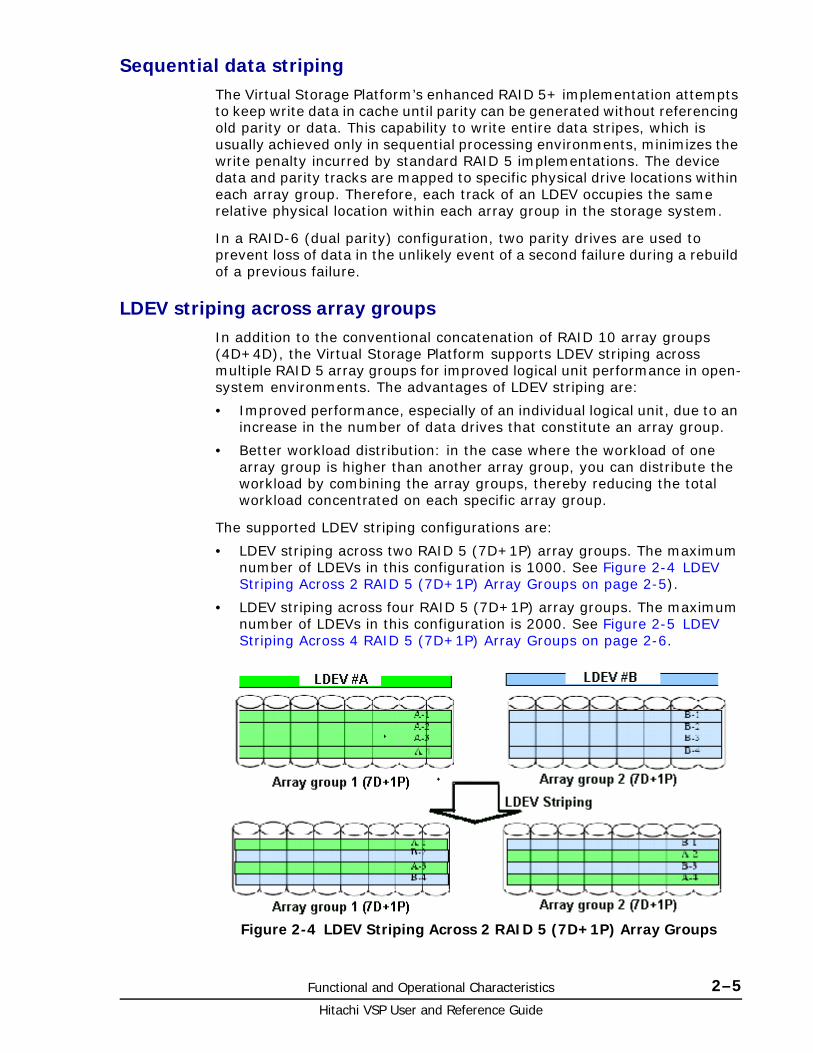
Sequential data stripingThe Virtual Storage Platform’s enhanced RAID 5+ implementation attempts to keep write data in cache until parity can be generated without referencing old parity or data. This capability to write entire data stripes, which is usually achieved only in sequential processing environments, minimizes the write penalty incurred by standard RAID 5 implementations. The device data and parity tracks are mapped to specific physical drive locations within each array group. Therefore, each track of an LDEV occupies the same relative physical location within each array group in the storage system.
In a RAID-6 (dual parity) configuration, two parity drives are used to prevent loss of data in the unlikely event of a second failure during a rebuild of a previous failure.
LDEV striping across array groupsIn addition to the conventional concatenation of RAID 10 array groups (4D+4D), the Virtual Storage Platform supports LDEV striping across multiple RAID 5 array groups for improved logical unit performance in open-system environments. The advantages of LDEV striping are:
• Improved performance, especially of an individual logical unit, due to an increase in the number of data drives that constitute an array group.
• Better workload distribution: in the case where the workload of one array group is higher than another array group, you can distribute the workload by combining the array groups, thereby reducing the total workload concentrated on each specific array group.
The supported LDEV striping configurations are:
• LDEV striping across two RAID 5 (7D+1P) array groups. The maximum number of LDEVs in this configuration is 1000. See Figure 2-4 LDEV Striping Across 2 RAID 5 (7D+1P) Array Groups on page 2-5).
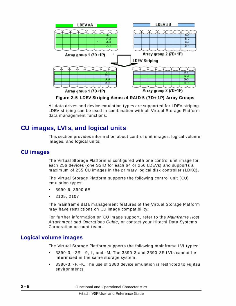
• LDEV striping across four RAID 5 (7D+1P) array groups. The maximum number of LDEVs in this configuration is 2000. See Figure 2-5 LDEV Striping Across 4 RAID 5 (7D+1P) Array Groups on page 2-6.
Figure 2-4 LDEV Striping Across 2 RAID 5 (7D+1P) Array Groups
Hitachi VSP User and Reference Guide
2–6 Functional and Operational Characteristics
All data drives and device emulation types are supported for LDEV striping. LDEV striping can be used in combination with all Virtual Storage Platform data management functions.
CU images, LVIs, and logical unitsThis section provides information about control unit images, logical volume images, and logical units.
CU imagesThe Virtual Storage Platform is configured with one control unit image for each 256 devices (one SSID for each 64 or 256 LDEVs) and supports a maximum of 255 CU images in the primary logical disk controller (LDKC).
The Virtual Storage Platform supports the following control unit (CU) emulation types:
• 3990-6, 3990 6E
• 2105, 2107
The mainframe data management features of the Virtual Storage Platform may have restrictions on CU image compatibility.
For further information on CU image support, refer to the Mainframe Host Attachment and Operations Guide, or contact your Hitachi Data Systems Corporation account team.
Logical volume imagesThe Virtual Storage Platform supports the following mainframe LVI types:
• 3390-3, -3R, -9, L, and -M. The 3390-3 and 3390-3R LVIs cannot be intermixed in the same storage system.
• 3380-3, -F, -K. The use of 3380 device emulation is restricted to Fujitsu environments.
Figure 2-5 LDEV Striping Across 4 RAID 5 (7D+1P) Array Groups

Functional and Operational Characteristics 2–7Hitachi VSP User and Reference Guide
The LVI configuration of the Virtual Storage Platform storage system depends on the RAID implementation and physical data drive capacities. The LDEVs are accessed using a combination of logical disk controller number (00-01), CU number (00-FE), and device number (00-FF). All control unit images can support an installed LVI range of 00 to FF.
Logical unitsThe Virtual Storage Platform storage system is configured with OPEN-V logical unit types. The OPEN-V logical unit can vary in size from 48.1 MB to 4 TB. For information on other logical unit types (e.g., OPEN-9), contact Hitachi Data Systems support.
For maximum flexibility in logical unit configuration, the Virtual Storage Platform provides the VLL and LUN Expansion (LUSE) features. Using VLL, users can configure multiple logical units under a single LDEV. Using Virtual LVI or LUSE, users can concatenate multiple logical units into large volumes. For further information on VLL and Virtual LVI, see the Performance Guide and the Provisioning Guide for Open Systems
Mainframe operationsThis section provides high-level descriptions of mainframe compatibility, support, and configuration.
Mainframe compatibility and functionalityIn addition to full System-Managed Storage (SMS) compatibility, the Virtual Storage Platform storage system provides the following functions and support in the mainframe environment:
• Sequential data striping
• Cache fast write (CFW) and DASD fast write (DFW)
• Enhanced dynamic cache management
• Extended count key data (ECKD) commands
• Multiple Allegiance
• Concurrent Copy (CC)
• Peer-to-Peer Remote Copy (PPRC)
• Compatible FlashCopy® V2
• Parallel Access Volume (PAV)
• Enhanced CCW
• Priority I/O queuing
• Red Hat Linux for IBM S/390 and zSeries

Hitachi VSP User and Reference Guide
2–8 Functional and Operational Characteristics
Mainframe operating system supportThe Virtual Storage Platform storage system supports most major IBM Mainframe operating systems and Open System operating systems, such as Microsoft Windows, Oracle Solaris, IBM AIX, Linux, HP-UX, and VMware. For more complete information on the supported operating systems, go to: http://www.hds.com/products/interoperability/index.htm
Mainframe configurationAfter a Virtual Storage Platform storage system has been installed, users can configure the storage system for mainframe operations.
See the following user documents for information and instructions on configuring your Virtual Storage Platform storage system for mainframe operations:
• The Mainframe Host Attachment and Operations Guide describes and provides instructions for configuring the Virtual Storage Platform for mainframe operations, including FICON attachment, hardware definition, cache operations, and device operations.
For detailed information on FICON connectivity, FICON/Open intermix configurations, and supported HBAs, switches, and directors for Virtual Storage Platform, please contact Hitachi Data Systems support.
• The Hitachi Storage Navigator User Guide provides instructions for installing, configuring, and using Storage Navigator to perform resource and data management operations on the Virtual Storage Platform storage systems.
• The Provisioning Guide for Mainframe Systems and Hitachi Volume Shredder User Guide provides instructions for converting single volumes (LVIs) into multiple smaller volumes to improve data access performance.
System option modes, host modes, and host mode optionsThis section provides detailed information about system option modes, host modes and host mode options.
System option modesTo provide greater flexibility and enable the Virtual Storage Platform to be tailored to unique customer operating requirements, additional operational parameters, or system option modes, are available. At installation, the modes are set to their default values, as shown in the following table. Be sure to discuss these settings with your Hitachi Data Systems team if you think changes should be made. The system option modes can only be changed by a Hitachi Data Systems representative.
The following tables provide information about system option modes and and SVP operations:
• Table 2-1 System option modes on page 2-9 lists the public system option mode information for Virtual Storage Platform. These can be used as needed.

Functional and Operational Characteristics 2–9Hitachi VSP User and Reference Guide
• Table 2-2 Mode 269: Storage Navigator Operations on page 2-54 specifies the details for mode 269 for Storage Navigator operations.
• Table 2-3 Mode 269: SVP Operations on page 2-54 specifies the details of mode 269 for SVP operations.
The following tables were up to date at the time this manual was published. However, the system option mode information may change in firmware releases that may happen before the next release of this manual. Contact Hitachi Data Systems support for the latest information on the Virtual Storage Platform system option modes.
The system option mode information includes:
• Mode: Specifies the system option mode number.
• Category: Indicates the functions to which the mode applies.
• Description: Describes the action or function that the mode provides.
• Default: Specifies the default setting (ON or OFF) for the mode.
• MCU/RCU: For remote functions, indicates whether the mode applies to the main control unit (MCU) and/or the remote control unit (RCU).
Table 2-1 System option modes
Mode Category Description Default MCU/RCU
20 Public
(Optional)
R-VOL read only function. OFF MCU
22 Common Regarding the correction copy or the drive copy, in case ECCs/LRC PINs are set on the track of copy source HDD, mode 22 can be used to interrupt the copy processing (default) or to create ECCs/LRC PINs on the track of copy target HDD to continue the processing.
Mode 22 = ON:
If ECCs/LRC PINs (up to 16) have been set on the track of copy source HDD, ECCs/LRC PINs (up to 16) will be created on the track of copy target HDD so that the copy processing will continue.
If 17 or more ECCs/LRC PINs are created, the corresponding copy processing will be interrupted.
Mode 22 = OFF (default)
If ECCs/LRC PINs have been set on the track of copy source HDD, the copy processing will be interrupted. (first recover ECCs/LRC PINs by using the PIN recovery flow, and then perform the correction copy or the drive copy again)
One of the controlling option for correction/drive copy.
OFF
36 HRC Sets default function (CRIT=Y) option for SVP panel (HRC).
OFF MCU

Hitachi VSP User and Reference Guide
2–10 Functional and Operational Characteristics
64 TrueCopy for Mainframe
Mode 64 = ON:
• When receiving the Freeze command, in the subsystem, pair volumes that fulfill the conditions below are suspended and the status change pending (SCP) that holds write I/Os from the host is set. The path between MCU and RCU is not deleted. Query is displayed only but unusable.
• When receiving the RUN command, the SCP status of the pairs that fulfill the conditions below is released.
• When a Failure Suspend occurs when Freeze Option Enable is set, except the pair in which the Failure Suspend occurs, other pairs that fulfill conditions below go into SCP state:
- TrueCopy Sync M-VOL
- Mainframe Volume
- Pair status: Duplex/Pending
Mode 64 = OFF (default):
• When receiving the Freeze command, pairs that fulfill the conditions below are suspended and the SCP is set. In the case of CU emulation type 2105/2017, the path between MCU and RCU is deleted, while the path is not deleted but unusable with Query displayed only in the case of CU emulation type 3990.
• When receiving the RUN command, the SCP status of the pairs that fulfill the conditions below is released.
• When a Failure Suspend occurs while the Freeze Option Enable is set, except the pair in which the Failure Suspend occurs, other pairs that fulfill the conditions below go into SCP state.
Conditions:
• TrueCopy Sync M-VOL
• Mainframe Volume
• Pair status: Duplex/Pending
• A pair whose RCU# is identical to the RCU for which the Freeze command is specified.
Mode Category Description Default MCU/RCU

Functional and Operational Characteristics 2–11Hitachi VSP User and Reference Guide
64 (cont)
TrueCopy for Mainframe
Notes:
1. When all the following conditions are met, set Mode 64=ON.
2. When all the following conditions are met, set Mode 64=ON.
- Customer requests to stop the update I/O operation to the RCU of a TrueCopy for Mainframe pair for the whole subsystem.
- Disaster Recovery function such as GDPS, HyperSwap, or Fail Over/ Fail Back, which requires compatibility with IBM storage, is not used as this Mode 64 operates without having compatibility with IBM storage.
- Only Peer-to-Peer-Remote-Copy operation. (Do not use it in combination with Business Continuity Manager.)
3. Even though the Failover command is not an applicable criterion, when executing the Failover command while Mode 114 is ON, since ports are not automatically switched, the Failover command fails.
4. With increase of Sync pairs in subsystem, the time period to report the completion of Freeze command and RUN command gets longer (estimate of time to report completion: 1 second per 1000 pairs), and MIH may occur.
. MCU/RCU
80 ShadowImage for Mainframe
• For RAID 300/400/450 (SI for OPEN or Mainframe) In response to the Restore instruction from the host or Storage Navigator, the following operation is performed regardless of specifying Quick or Normal.
• For RAID 500/600/700 (SI for OPEN) In response to the Restore instruction from the host, if neither Quick nor Normal is specified, the following operation is performed
Mode 80 = ON: Normal Restore / Reverse Copy is performed.
Mode 80 = OFF: Quick Restore is performed.
Notes.
1. This mode is applied when the specification for Restore of SI is switched between Quick (default) and Normal.
2. The performance of Restore differs depending on the Normal or Quick specification.
OFF -
87 ShadowImage Determines whether NormalCopy or QuickResync, if not specified, is performed at the execution of pairresync by CCI.
Mode 87 = ON: QuickResync is performed.
Mode 87 = OFF: NormalCopy is performed.
OFF -
104 HRC Changes the default CGROUP Freeze option. OFF MCU
Mode Category Description Default MCU/RCU

Hitachi VSP User and Reference Guide
2–12 Functional and Operational Characteristics
114 HRC This mode enables or disables the LCP/RCP port to be automatically switched over when the PPRC command ESTPATH/DELPATH is executed.
Mode 114 = ON:
Automatic port switching during ESTPATH/DELPATH is enabled.
Mode 114 = OFF (default):
Automatic port switching during ESTPATH/DELPATH is disabled.
Notes:
1. If you select an incorrect port while the mode is set to ON, and if ESTPATH is executed when no logic path exists, the port is switched to RCP..
2. Set this mode to OFF before using TPC-R (IBM software for disaster recovery).
OFF MCU
122 ShadowImage For Split or Resync request from the Mainframe host and Storage Navigator,
Mode 122 = ON:
• By specifying Split or Resync, Steady/Quick Split or Normal/Quick Resync is respectively executed in accordance with Normal/Quick setting
Mode 122 = OFF (default)?
• By specifying Split or Resync, Steady/Quick Split or Normal/Quick Resync is respectively executed in accordance with Normal/Quick setting. For details, see "SOM 122" sheet
Note:
(1) For RAID500 and later models, this mode is applied to use scripts etc that are used on RAID400 and 450 (2) In the case of RAID500 and later models, executing the pairresync command from RAID Manager may be related to the SOM 087 setting.
(3) When performing At-Time Split from RAID Manager
- Set this mode to OFF in the case of RAID450
- Set this mode to OFF or specify the environment variable HORCC_SPLT for Quick in the case of RAID500 and later.Otherwise, Pairsplit may turn timeout.
(4) The mode becomes effective after specifying Split/Resync following the mode setting. The mode function does not work if it is set during the Split/Resync operation
OFF -
187 Common Yellow Light Option (only for XP product) OFF -
190 HRC TCz – Allows you to update the VOLSER and VTOC of the R-VOL while the pair is suspended if both mode 20 and 190 are ON
OFF RCU
Mode Category Description Default MCU/RCU

Functional and Operational Characteristics 2–13Hitachi VSP User and Reference Guide
269 Common High Speed Format for CVS (Available for all dku emulation type)
(1) High Speed Format support
When redefining all LDEVs included in an ECC group using Volume Initialize or Make Volume on CVS setting panel, LDEV format, as the last process, will be performed in high speed.
(2) Make Volume feature enhancement
In addition, with supporting the feature, the Make Volume feature (recreating new CVs after deleting all volumes in a VDEV), which so far was supported for OPEN-V only, is available for all emulation types.
Mode 269 = ON:
The High Speed format is available when performing CVS operations on Storage Navigator or performing LDEV formats on the Maintenance window of the SVP for all LDEVs in a parity group.
Mode 269 = OFF (default):
As usual, only the low speed format is available when performing CVS operations on Storage Navigator. In addition, the LDEV specifying format on the Maintenance window of the SVP is in low speed as well.
Notes:
1. For more details about mode 269, see worksheet "Mode269 detail for RAID700".
2. Mode 269 is effective only when using the SVP to format the CVS.
OFF MCU/RCU
278 Open Tru64 (Host Mode 07) and OpenVMS (Host Mode 05)
Caution: Host offline: Required
OFF -
292 HRC Issuing OLS when Switching Port
In case the mainframe host (FICON) is connected with the CNT-made FC switch (FC9000 etc.), and is using along with the TrueCopy S/390 with Open Fibre connection, the occurrence of Link Incident Report for the mainframe host from the FC switch will be deterred when switching the CHT port attribute (including automatic switching when executing CESTPATH and CDELPATH in case of Mode 114=ON).
Mode 292=ON:
When switching the port attribute, issue the OLS (100ms) first, and then reset the Chip.
Mode 292=OFF (default):
When switching the port attribute, reset the Chip without issuing the OLS.
OFF MCU/RCU
Mode Category Description Default MCU/RCU

Hitachi VSP User and Reference Guide
2–14 Functional and Operational Characteristics
305 Mainframe This mode enables the pre-label function (creation of VTOC including VOLSER).
Mode 305 = ON:
Pre-label function is enabled
Note:
1. Set SOM 305 to ON before performing LDEV Format for a mainframe volume if you want to perform OS IPL (volume online) without fully initializing the volume after the LDEV Format. However, full initialization is required in actual operation.
2. Processing time of LDEV format increases by as much as full initialization takes.
3. The following functions and conditions are not supported.
Quick format
3390-A (Dynamic Provisioning attribute)
Volume Shredder
4. Full initialization is required in actual operation.
OFF MCU/RCU
308 TrueCopy for Mainframe
Universal Replicator for Mainframe
SIM RC=2180 option
<Description>
SIM RC=2180 (RIO path failure between MCU and RCU) was not reported to host. DKC reports SSB with F/M=F5 instead of reporting SIM RC=2180 in the case. Micro-program has been modified to report SIM RC=2180 with newly assigned system option Mode as individual function for specific customer.
Usage:
Mode 308 = ON
SIM RC 2180 is reported which is compatible with older Hitachi specification
Mode 308 = OFF
Reporting is compatible with IBM - Sense Status report of F5.
OFF MCU
448 Universal Replicator
Universal Replicator for Mainframe
Mode 448 = ON: (Enabled)
If the SVP detects a blocked path, the SVP assumes that an error occurred, and then immediately splits (suspends) the mirror.
Mode 448 = OFF: (Disabled)
If the SVP detects a blocked path and the path does not recover within the specified period of time, the SVP assumes that an error occurred, and then splits (suspends) the mirror.
Note:
The mode 448 setting takes effect only when mode 449 is set to OFF.
OFF
Mode Category Description Default MCU/RCU

Functional and Operational Characteristics 2–15Hitachi VSP User and Reference Guide
449 Universal Replicator
Universal Replicator for Mainframe
Detecting and monitoring path blockade between MCU and RCU of Universal Replicator/Universal Replicator for z/OS
<Functionality>
- Mode 449 on: Detecting and monitoring of path blockade will NOT be performed.
- Mode 449 off (default *) : Detecting and monitoring of the path blockade will be performed.
* Newly shipped DKC will have Mode 449 = ON as default.
Note: The mode status will not be changed by the microcode exchange.
454 Virtual Partition Manager
CLPR (Function of Virtual Partition Manager) partitions the cache memory in the disk subsystem into multiple virtual cache and assigns the partitioned virtual cache for each use. If a large amount of cache is required for a specific use, it can minimize the impact on other uses. The CLPR function works as follows depending on whether SOM 454 is set to ON or OFF.
Mode 454 = OFF (default):
The amount of the entire destage processing is periodically determined by using the highest workload of all CLPRs (*a). (The larger the workload is, the larger the amount of the entire destage processing becomes.)
*a: (Write Pending capacity of CLPR#x) ÷ (Cache capacity of CLPR#x), x=0 to 31
CLPR whose value above is the highest of all CLPRs
Because the destage processing would be accelerated depending on CLPR with high workload, when the workload in a specific CLPR increases, the risk of host I/O halt would be reduced.
Therefore, set Mode 454 to OFF in most cases.
Mode 454 = ON:
The amount of the entire destage processing is periodically determined by using the workload of the entire system (*b). (The larger the workload is, the larger the amount of the entire destage processing becomes.)
*b: (Write Pending capacity of the entire system) ÷ (Cache capacity of the entire system)
Because the destage processing would not be accelerated even if CLPR has high workload, when the workload in a specific CLPR increases, the risk of host I/O halt would be increased. Therefore, it is limited to set Mode 454 to ON only when a CLPR has constant high workload and it gives priority to I/O
OFF
Mode Category Description Default MCU/RCU

Hitachi VSP User and Reference Guide
2–16 Functional and Operational Characteristics
457 Universal Volume Manager
1. High Speed LDEV Format for External Volumes
Mode 457 = ON: The high speed LDEV format for external volumes is available by setting system option mode 457 to ON. When System Option Mode 457 is ON, when selecting the external volume group and performing the LDEV format, any Write processing on the external logical units will be skipped. However, if the emulation type of the external LDEV is a mainframe system, the Write processing for mainframe control information only will be performed after the write skip.
2. Support for Mainframe Control Block Write GUIMode 457 = ON: The high speed LDEV format for external volumes is supported. Control Block Write of the external LDEVs in Mainframe emulation is supported by Storage Navigator (GUI).
Notes:
1. If the LDEV is not written with data “0” before performing the function, the LDEV format may fail.
2. After the format processing, make sure to set system option mode 457 to OFF.
OFF MCU/RCU
459 ShadowImage for Mainframe, ShadowImage
When the secondary volume of an SI/SIz pair is an external volume, the transaction to change the status from SP-PEND to SPLIT is as follows:
1. Mode 459 = ON when creating an SI/SIz pair: The copy data is created in cache memory. When the write processing on the external storage completes and the data is fixed, the pair status will change to SPLIT.
2. Mode 459 = OFF when creating an SI/SIz pair Once the copy data has been created in cache memory, the pair status will change to SPLIT. The external storage data is not fixed (current spec).
OFF -
464 TrueCopy for Mainframe
SIM Report without Inflow Limit
For TC, the SIM report for the volume without inflow limit is available when mode 464 is set to ON.
SIM: RC=490x-yy (x=CU#, yy=LDEV#)
OFF MCU
Mode Category Description Default MCU/RCU

Functional and Operational Characteristics 2–17Hitachi VSP User and Reference Guide
466 Universal Replicator, Universal Replicator for Mainframe
For UR/URz operations it is strongly recommended that the path between main and remote storage systems have a minimum data transfer speed of 100 Mbps. If the data transfer speed falls to 10 Mbps or lower, UR operations cannot be properly processed. As a result, many retries occur and UR pairs may be suspended. Mode 466 is provided to ensure proper system operation for data transfer speeds of at least 10 Mbps.
Mode 466 = ON: Data transfer speeds of 10 Mbps and higher are supported. The JNL read is performed with 4-multiplexed read size of 256 KB.
Mode 466 = OFF: For conventional operations. Data transfer speeds of 100 Mbps and higher are supported. The JNL read is performed with 32-multiplexed read size of 1 MB by default.
Note: The data transfer speed can be changed using the Change JNL Group options.
OFF
467 ShadowImage, ShadowImage for Mainframe,Compatible FlashCopy® V2, Snapshot, Volume Migration, Universal Volume Manager
For the following features, the current copy processing slows down when the percentage of “dirty” data is 60% or higher, and it stops when the percentage is 75% or higher. Mode 467 is provided to prevent the percentage from exceeding 60%, so that the host performance is not affected.
ShadowImage, ShadowImage for Mainframe, Compatible FlashCopy® V2, Snapshot, Volume Migration, Universal Volume Manager
Mode 467 = ON: Copy overload prevention. Copy processing stops when the percentage of “dirty” data reaches 60% or higher. When the percentage falls below 60%, copy processing restarts.
Mode 467 = OFF: Normal operation. The copy processing slows down if the dirty percentage is 60% or larger, and it stops if the dirty percentage is 75% or larger.
Caution: This mode must always be set to ON when using an external volume as the secondary volume of any of the above-mentioned replication products.
Note: It takes longer to finish the copy processing because it stops for prioritizing the host I/O performance.
ON
Mode Category Description Default MCU/RCU

Hitachi VSP User and Reference Guide
2–18 Functional and Operational Characteristics
471 Copy-on-Write Snapshot
(Earlier than 70-05-0x-00/00)
Copy-on-Write Snapshot, Hitachi Thin Image
(70-05-0x-00/00 or higher)
Since the SIM-RC 601xxx that are generated when the usage rate of Pool used by Snapshot exceeds the threshold value can be resolved by users, basically they are not reported to the maintenance personnel.
This option is used to inform maintenance personnel of these SIMs that are basically not reported to maintenance personnel in case these SIMs must be reported to them.
SIMs reported by setting the mode to ON are:
• SIM-RC 601xxx (Pool utilization threshold excess) (Earlier than 70-05-0x-00/00)
• SIM-RC 601xxx (Pool utilization threshold excess)/ 603000 (SM Space Warning) (70-05-0x-00/00 or higher:)
Mode 471 = ON:
This kind of SIMs is reported to maintenance personnel.
Mode 471 = OFF (default):
This kind of SIMs is not reported to maintenance personnel.
Note: Set this mode to ON when it is required to inform maintenance personnel of the SIM-RC (*)
SIMs reported by setting the mode to ON are:
• SIM-RC 601xxx (Pool utilization threshold excess) (Earlier than 70-05-0x-00/00)
• SIM-RC 601xxx (Pool utilization threshold excess)/ 603000 (SM Space Warning) (70-05-0x-00/00 or higher:)
OFF
Mode Category Description Default MCU/RCU
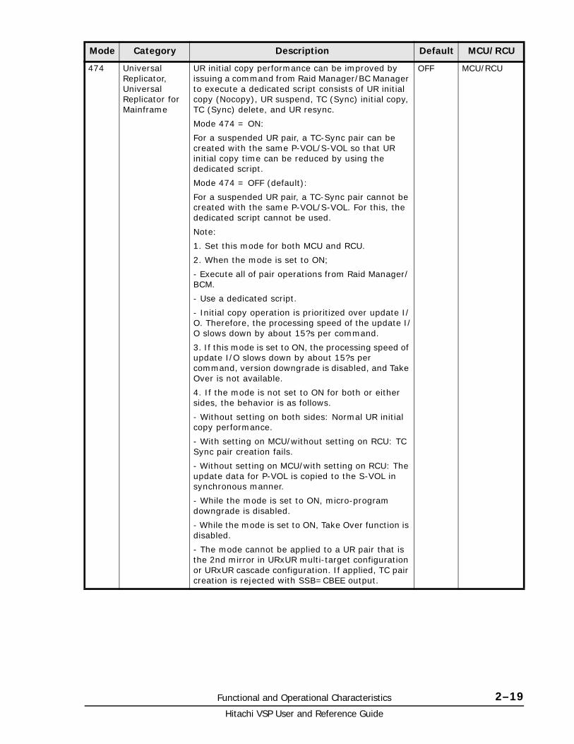
Functional and Operational Characteristics 2–19Hitachi VSP User and Reference Guide
474 Universal Replicator, Universal Replicator for Mainframe
UR initial copy performance can be improved by issuing a command from Raid Manager/BC Manager to execute a dedicated script consists of UR initial copy (Nocopy), UR suspend, TC (Sync) initial copy, TC (Sync) delete, and UR resync.
Mode 474 = ON:
For a suspended UR pair, a TC-Sync pair can be created with the same P-VOL/S-VOL so that UR initial copy time can be reduced by using the dedicated script.
Mode 474 = OFF (default):
For a suspended UR pair, a TC-Sync pair cannot be created with the same P-VOL/S-VOL. For this, the dedicated script cannot be used.
Note:
1. Set this mode for both MCU and RCU.
2. When the mode is set to ON;
- Execute all of pair operations from Raid Manager/ BCM.
- Use a dedicated script.
- Initial copy operation is prioritized over update I/O. Therefore, the processing speed of the update I/O slows down by about 15?s per command.
3. If this mode is set to ON, the processing speed of update I/O slows down by about 15?s per command, version downgrade is disabled, and Take Over is not available.
4. If the mode is not set to ON for both or either sides, the behavior is as follows.
- Without setting on both sides: Normal UR initial copy performance.
- With setting on MCU/without setting on RCU: TC Sync pair creation fails.
- Without setting on MCU/with setting on RCU: The update data for P-VOL is copied to the S-VOL in synchronous manner.
- While the mode is set to ON, micro-program downgrade is disabled.
- While the mode is set to ON, Take Over function is disabled.
- The mode cannot be applied to a UR pair that is the 2nd mirror in URxUR multi-target configuration or URxUR cascade configuration. If applied, TC pair creation is rejected with SSB=CBEE output.
OFF MCU/RCU
Mode Category Description Default MCU/RCU

Hitachi VSP User and Reference Guide
2–20 Functional and Operational Characteristics
484 TrueCopy for Mainframe
ShadowImage for Mainframe
The IBM-compatible PPRC FC path interface has been supported with RAID500 50-06-11-00/00. As the specification of QUERY display using this interface (hereinafter called New Spec) is different from the current specification (hereinafter called Previous Spec), this mode enables to display the PPRC path QUERY with the New Spec or Previous Spec.
Mode 484 = ON:
PPRC path QUERY is displayed with the New Spec.
Mode 484 = OFF (default):
PPRC path QUERY is displayed with the Previous Spec
(ESCON interface).
Note:
(1) Set this mode to ON when you want to maintain compatibility with the Previous Spec for PPRC path QUERY display under the environment where IBM host function (such as PPRC and GDPS) is used.
(2) When an old model or a RAID500 that doesn’t support this mode is connected using TCz, set this mode to OFF.
(3) If the display specification is different between MCU and RCU, it may cause malfunction of host.
(4) When TPC-R is used, which is IBM software for disaster recovery, set this mode to ON.
OFF MCU/RCU
Mode Category Description Default MCU/RCU

Functional and Operational Characteristics 2–21Hitachi VSP User and Reference Guide
491 ShadowImage
ShadowImage for Mainframe
Mode 491 is used for improving the performance of ShadowImage/ ShadowImage for Mainframe/ ShadowImage FCv1.
Mode ON: The option (Reserve05) of ShadowImage/ ShadowImage for Mainframe is available. If the option is set to ON, the copy of ShadowImage/ ShadowImage for Mainframe/ ShadowImage FCv1 will be performed from 64 processes to 128 processes so that the performance will be improved.
Mode OFF (default): The option (Reserve05) of ShadowImage/ ShadowImage for Mainframe is unavailable. The copy ofShadowImage/ ShadowImage for Mainframe/ ShadowImage FCv1 is performed with 64 processes.
Note:
1. Make sure to apply mode 491 when the performance of ShadowImage/ ShadowImage for Mainframe/ ShadowImage FCv1 is considered to be important.
2. Make sure not to apply the mode when the host I/O performance is considered to be important.
3. The mode will be noneffective if 3 or more pairs of DKAs are not mounted.
4. Make sure to set mode 467 to OFF when using mode 491, since the performance may not improve.
5. The mode is noneffective for the NSC model.
OFF .
495 NAS Function:
That the secondary volume where S-VOL Disable is set means the NAS file system information is imported in the secondary volume. If the user has to take a step to release the S-VOL Disable attribute in order to perform the restore operation, it is against the policy for the guard purpose and the guard logic to have the user uninvolved. In this case, in the NAS environment, Mode 495 can be used to enable the restore operation.
Mode 495 = ON:
The restore operation ?Reverse Copy, Quick Restore) is allowed on the secondary volume where S-VOL Disable is set.
Mode 495 = OFF (default):
The restore operation ?Reverse Copy, Quick Restore) is not allowed on the secondary volume where S-VOL Disable is set.
OFF
Mode Category Description Default MCU/RCU

Hitachi VSP User and Reference Guide
2–22 Functional and Operational Characteristics
506 Universal Replicator, Universal Replicator for Mainframe
This option is used to enable Delta Resync with no host update I/O by copying only differential JNL instead of copying all data.
The HUR Differential Resync configuration is required.
Mode 506 = ON:
Without update I/O: Delta Resync is enabled.
With update I/O: Delta Resync is enabled.
Mode 506 = OFF (default):
Without update I/O: Total data copy of Delta Resync is performed.
With update I/O: Delta Resync is enabled.
Note:
Even when mode 506 is set to ON, the Delta Resync may fail and only the total data copy of the Delta Resync function is allowed if the necessary journal data does not exist on the primary subsystem used for the Delta Resync operation.
OFF MCU/RCU
530 Universal Replicator for Mainframe
When a Universal Replicator for Mainframe pair is in the Duplex state, this option switches the display of Consistency Time (C/T) between the values at JNL restore completion and at JNL copy completion.
Mode 530 = ON:
- C/T displays the value of when JNL copy is completed.
Mode 530 = OFF (default):
C/T displays the value of when JNL restore is completed.
Note:
At the time of Purge suspend or RCU failure suspend, the C/T of Universal Replicator for Mainframe displayed by Business Continuity Manager or Storage Navigator may show earlier time than the time showed when the pair was in the Duplex state.
OFF RCU
531 Open and Mainframe
When PIN data is generated, the SIM currently stored in SVP is reported to the host.
Mode 531 = ON:
The SIM for PIN data generation is stored in SVP and reported to the host.
Mode 531 = OFF:
The SIM for PIN data generation is stored in SVP only, not reported to the host, the same as the current specification.
OFF MCU/RCU
Mode Category Description Default MCU/RCU

Functional and Operational Characteristics 2–23Hitachi VSP User and Reference Guide
548 TrueCopy for Mainframe, Universal Replicator for Mainframe, or ShadowImage for Mainframe from BCM
This option prevents pair operations of TCz, URz, or SIz via Command Device online.
Mode 548 = ON:
Pair operations of TC for z/OS, UR for z/OS, or SI for z/OS via online Command Device are not available. SSB=0x64fb is output.
Mode 548 = OFF:
Pair operations of TC for z/OS, UR for z/OS, or SI for z/OS via online Command Device are available. SIM is output.
Note:
1. When Command Device is used online, if a script containing an operation via Command Device has been executed, the script may stop if this option is set to ON. As described in the BCM user’s guide, the script must be performed with Command Device offline.
2. This option is applied to operations from BCM that is operated on MVS.
556 Open Prevents an error code from being set in the 8 - 11th bytes in the standard 16-byte sense byte.
Mode 556 = ON:
An error code is not set in the 8 - 11th bytes in the standard 16-byte sense byte.
Mode 556 = OFF (default):
An error code is set in the 8 - 11th bytes in the standard 16-byte sense byte.
OFF MCU/RCU
561 ShadowImage, Universal Volume Manager
Allows Quick Restore for external volumes with different Cache Mode settings.
Mode 561 = ON:
Quick Restore for external volumes with different Cache Mode settings is prevented.
Mode 561 = OFF (default):
Quick Restore for external volumes with different Cache Mode settings is allowed.
OFF MCU/RCU
Mode Category Description Default MCU/RCU
Hitachi VSP User and Reference Guide
2–24 Functional and Operational Characteristics
573 TrueCopy for Mainframe
ShadowImage for Mainframe
For the DKU emulation type 2105/2107, specifying the CASCADE option for the ICKDSF ESTPAIR command is allowed.
Mode 573 = ON:
The ESTPAIR CASCADE option is allowed.
Mode 573 = OFF (default):
The ESTPAIR CASCADE option is not allowed. (When specified, the option is rejected.)
Notes:
1. When DKC emulation type is 2105/2107, this mode is applied in the case where pair creation in TCz – SIz cascading configuration in the ICKDSF environment fails with the following message output.
Message: ICK30111I DEVICE SPECIFIED IS THE SECONDARY OF A DUPLEX OR PPRC PAIR
2. The CASCADE option can be specified in the TSO environment also.
3. Although the CASCADE option can be specified for the ESTPAIR command, the PPRC-XD function is not supported.
4. Perform thorough pre-check for any influence on GDPS/PPRC.
5. The SOM must be enabled only when the CASCADE option is specified for the ESTPAIR command for the DKC emulation type 2105/2107.
OFF MCU/RCU
The unit where TCz and SIz in a cascading configuration use the same volume
589 Universal Volume Manager
Turning this option ON changes the frequency of progress updates when disconnecting an external volume. of disconnection is changed.
improvement in destaging to the pool by achieving efficient HDD access.
Mode 589 = ON: For each external volume, progress is updated only when the progress rate is 100%
Mode 589 = OFF (default): Progress is updated when the progress rate exceeds the previous level.
Notes:
1. Set this option to ON when disconnecting an external volume while the specific host IO operation is online and its performance requirement is severe.
2. Whether the disconnecting status for each external volume is progressed or not cannot be confirmed on Storage Navigator (It indicates “-“ until just before the completion and at the last it changes to 100%).
OFF .
Mode Category Description Default MCU/RCU

Functional and Operational Characteristics 2–25Hitachi VSP User and Reference Guide
598 Universal Replicator for Mainframe
This mode is used to report SIMs (RC=DCE0 to DCE3) to a Mainframe host to warn that a URz journal is full.
Mode 598 = ON:
SIMs (RC=DCE0 to DEC3) to warn that a JNL is full are reported to SVP and the host.
Mode 598= OFF (default):
SIMs (RC=DCE0 to DEC3) to warn that a JNL is full are reported to SVP only.
Notes:
1. This mode is applied if SIMs (RC=DCE0 to DCE3) need to be reported to a Mainframe host.
2. The SIMs are not reported to the Open server.
3. SIMs for JNL full (RC=DCE0 and DCE1) on MCU are reported to the host connected with MCU.
4. SIMs for JNL full (RC=DCE2 and DCE3) on RCU are reported to the host connected with RCU.
ON .
676 Audit Log This option is used to set whether an audit log is to be stored onto the system disk or not.
Mode 676 = ON:
An audit log is stored onto the system disk.
Mode 676 = OFF (default):
An audit log is not stored onto the system disk.
This mode is also enabled/disabled by enabling/disabling Audit Log Buffer on the [Audit Log Setting...] window, which can be opened by selecting [Settings] -> [Security] -> [Audit Log Setting...] on Storage Navigator.
Notes:
1. 1. This option is applied to the sites where the level of importance of an audit log is high.
2. A system disk with available space of more than 130 MB (185 cylinders when the track format is 3380/6586/NF80, and 154 cylinders when the track format is 3390/6588) must exist. (Otherwise, audit log is not stored even this option is ON).
3. Make sure to turn this option on after preparing a normal system disk that meets the condition in (2). If Define Configuration & Install is performed, turn this option on after formatting the system disk.
OFF .
Mode Category Description Default MCU/RCU

Hitachi VSP User and Reference Guide
2–26 Functional and Operational Characteristics
689 TrueCopy for Mainframe
ShadowImage for Mainframe
This option is used to slow down the initial copy and resync copy operations when the Write Pending rate on RCU exceeds 60%.
Mode 689 = ON:
The initial copy and resync copy operations are slowed down when the Write Pending rate on RCU exceeds 60%.
*: From RAID700, if the Write Pending rate of CLPR where the initial copy target secondary volume belongs to is not over 60% but that of MP PCB where the S-VOL belongs to is over 60%, the initial copy operation is slowed down.
Mode 689 = OFF (default):
The initial copy and resync copy operations are not slowed down when the Write Pending rate on RCU exceeds 60% (the same as before).
Note:
1. 1. This mode can be set online.
2. 2. The micro-programs on both MCU and RCU must support this mode.
3. 3. This mode should be set per customer’s requests.
4. 4. If the Write Pending status long keeps 60% or more on RCU, it takes extra time for the initial copy and resync copy to be completed by making up for the slowed down copy operation.
5. 5.From RAID700, if the Write Pending rate of CLPR where the initial copy target secondary volume belongs to is not over 60% but that of MP PCB where the S-VOL belongs to is over 60%, the initial copy operation is slowed down.
OFF .
Mode Category Description Default MCU/RCU

Functional and Operational Characteristics 2–27Hitachi VSP User and Reference Guide
690 Universal Replicator, Universal Replicator for Mainframe
This option is used to prevent Read JNL or JNL Restore when the Write Pending rate on RCU exceeds 60% as follows:
• When CLPR of JNL-Volume exceeds 60%, Read JNL is prevented.
• When CLPR of Data (secondary)-Volume exceeds 60%, JNL Restore is prevented.
Mode 690 = ON:
Read JNL or JNL Restore is prevented when the Write Pending rate on RCU exceeds 60%.
Mode 690 = OFF (default):
Read JNL or JNL Restore is not prevented when the Write Pending rate on RCU exceeds 60% (the same as before).
Notes:
1. This mode can be set online.
2. This mode should be set per customer’s requests.
3. If the Write Pending status long keeps 60% or more on RCU, it takes extra time for the initial copy to be completed by making up for the prevented copy operation.
4. If the Write Pending status long keeps 60% or more on RCU, the pair status may become Suspend due to the JNL-Vol being full.
OFF .
696 Open This mode is available to enable or disable the QoS function.
Mode 696 = ON:
QoS is enabled. (In accordance with the Share value set to SM, I/Os are scheduled. The Share value setting from RMLIB is accepted)
Mode 696 = OFF (default):
QoS is disabled. (The Share value set to SM is cleared. I/O scheduling is stopped. The Share value setting from host is rejected)
Note:
1. Set this mode to ON when you want to enable the QoS function.
OFF .
Mode Category Description Default MCU/RCU

Hitachi VSP User and Reference Guide
2–28 Functional and Operational Characteristics
701 Universal Volume Manager
Issues the Read command at the logical unit discovery operation using UVM.
Mode 701 = ON:
The Read command is issued at the logical unit discovery operation.
Mode 701 = OFF:
The Read command is not issued at the logical unit discovery operation.
Notes:
1. When the Open LDEV Guard attribute (VMA) is defined on an external device, set the system option to ON.
2. When this option is set to ON, it takes longer time to complete the logical unit discovery. The amount of time depends on external storages.
3. With this system option OFF, if searching for external devices with VMA set, the VMA information cannot be read.
4. When the mode is set to ON while the following conditions are met, the external volume is blocked.
a. RAID700 70-03-3x-00/00 or higher version is used on the storage system.
b. An external volume to which Nondisruptive Migration (NDM) attribute is set exists.
c. The external volume is reserved by the host
5. As the VMA information is USP/NSC specific, this mode does not need to be ON when the external storage is other than USP/NSC.
6. Set the mode to OFF when the following conditions are met.
a. RAID700 70-03-3x-00/00 or higher version is used on the storage system
b. An external volume to which Nondisruptive Migration (NDM) attribute is set exists.
OFF .
Mode Category Description Default MCU/RCU

Functional and Operational Characteristics 2–29Hitachi VSP User and Reference Guide
704 Open and Mainframe
To reduce the chance of MIH, this option can reduce the priority of SI, VM, CoW Snapshot, Flash Copy or Resync copy internal IO requests so that host IO has a higher priority. This mode creates new work queues where these jobs can be assigned with a lower priority.
Mode 704 = ON:
Copy processing requested is registered into a newly created queue so that the processing is scheduled with lower priority than host I/O.
Mode 704 = OFF: (Default)
Copy processing requested is not registered into a newly created queue. Only the existing queue is used.
Note:
If the PDEV is highly loaded, the priority of Read/Write processing made by SI, VM, Snapshot, Compatible FlashCopy® V2 or Resync may become lower. As a consequence the copy speed may be slower.
OFF .
720 Universal Volume Manager (Mainframe and Open)
Supports the Active Path Load Balancing (APLB) mode.
Mode 720 = ON:
The alternate path of EVA (A/A) is used in the APLB mode.
Mode 720 = OFF (default):
The alternate path of EVA (A/A) is used in the Single mode.
Note:
Though online setting is available, the setting will not be enabled until Check Paths is performed for the mapped external device.
OFF .
Mode Category Description Default MCU/RCU

Hitachi VSP User and Reference Guide
2–30 Functional and Operational Characteristics
721 Open and Mainframe
When a parity group is uninsulated or installed, the following operation is performed according to the setting of mode 721.
Mode 721 = ON:
When a parity group is uninstalled or installed, the LED of the drive for uninstallation is not illuminated, and the instruction message for removing the drive does not appear. Also, the windows other than that of parity group, such as DKA or DKU, are unavailable to select.
Mode 721 = OFF (default):
When a parity group is uninstalled or installed, the operation is as before: the LED of the drive is illuminated, and the drive must be unmounted and remounted.
Notes:
1. When the RAID level or emulation type is changed for the existing parity group, this option should be applied only if the drive mounted position remains the same at the time of the parity group uninstallation or installation.
2. After the operation using this option is completed, the mode must be set back to OFF; otherwise, the LED of the drive to be removed will not be illuminated at subsequent parity group uninstalling operations.
OFF .
Mode Category Description Default MCU/RCU

Functional and Operational Characteristics 2–31Hitachi VSP User and Reference Guide
725
part 1 of 2
Universal Volume Manager
This option determines the action that will be taken when the status of an external volume is Not Ready
Mode 725 = ON:
When Not Ready is returned, the external path is blocked and the path status can be automatically recovered (Not Ready blockade). Note that the two behaviors, automatic recovery and block, may be repeated.
For version 60-05-06-00/00 and later, when the status of a device is Not Ready blockade, Device Health Check is executed after 30 seconds.
Mode 725 = OFF (default):
When Not Ready is returned three times in three minutes, the path is blocked and the path status cannot be automatically recovered (Response error blockade).
Notes:
1. For R700 70-01-62-00/00 and lower (within 70-01-xx range)
Applying this SOM is prohibited when USP V/VM is used as an external subsystem and its external volume is DP-VOL.
Applying this SOM is recommended when the above condition (1) is not met and SUN storage is used as an external storage.
Applying this SOM is recommended if the above condition (1) is not met and a maintenance operation such as firmware update causing controller reboot is executed on the external storage side while a storage system other than Hitachi product is used as an external subsystem.
2. For R700 70-02-xx-00/00 and higher
Applying this SOM is prohibited when USP V/VM is used as an external subsystem and its external volume is DP-VOL.
Applying this SOM is recommended when the above condition (1) is not met and SUN storage is used as an external storage.
Applying this SOM is recommended when the above condition (1) is not met and EMC CX series or Fujitsu Fibre CAT CX series is used as an external storage.
Applying this SOM is recommended if the above condition (1) is not met and a maintenance operation such as firmware update causing controller reboot is executed on the external storage side while a storage system other than Hitachi product is used as an external subsystem.
(Continued below)
OFF .
Mode Category Description Default MCU/RCU
Hitachi VSP User and Reference Guide
2–32 Functional and Operational Characteristics
725
part 2 of 2
Universal Volume Manager
Notes: (continued)
3. While USP V/VM is used as an external subsystem and its volume is DP-VOL, if SOM e Pool-VOLs constituting the DP-VOL are blocked, external path blockade and recovery occurs repeatedly.
4. When a virtual volume mapped by UVM is set to pool-VOL and used as DP-VOL in local subsystem, this SOM can be applied without problem.
OFF .
729 Dynamic Provisioning
Data Retention Utility
To set the Protect attribute for the target DP-VOL using Data Retention Utility (DRU), when any write operation is requested to the area where the page allocation is not provided at a time when the HDP Pool is full.
Mode 729 = ON:
To set the Protect attribute for the target DP-VOL using DRU, when any write operation is requested to the area where the page allocation is not provided at a time when the HDP pool is full. (Not to set in the case of Read request.)
Mode 729 = OFF (default):
Not to set the Protect attribute for the target DP-VOL using DRU, when any write operation is requested to the area where the page allocation is not provided at a time when HDP pool is full.
Notes:
1. This SOM is applied when:
- The threshold of pool is high (e.g., 95%) and the pool may be full.
- File system is used.
- Data Retention Utility is installed.
2. Since the Protect attribute is set for V-VOL, the Read operation cannot be allowed as well.
3. When Data Retention Utility is not installed, the desired effect is not achieved.
4. Protect attribute can be released from the Data Retention window of Storage Navigator after releasing the full status of the pool by adding a Pool-VOL.
OFF .
Mode Category Description Default MCU/RCU
Functional and Operational Characteristics 2–33Hitachi VSP User and Reference Guide
733 Volume Migration,
ShadowImage,
ShadowImage for Mainframe
This option enables to suspend Volume Migration or Quick Restore operation during LDEV-related maintenance.
Mode 733 = ON:
Volume Migration or Quick Restore operation during LDEV-related maintenance is not suspended
Mode 733 = OFF (default):
Volume Migration or Quick Restore operation during LDEV-related maintenance is suspended
Notes:
1. This option should be applied when Volume Migration or Quick Restore operation can be suspended during LDEV-related maintenance.
2. Set mode 733 to ON if you want to perform any LDEV-related maintenance activities and you do not want these operations to fail when Volume Migration or Quick Restore is active.
3. This option is recommended as functional improvement to avoid maintenance failures. In SOM e cases of a failure in LDEV-related maintenance without setting the option, Storage Navigator operations may be unavailable.
4. There is the potential for LDEV-related maintenance activities to fail when Volume Migration and Quick Restore is active without setting the option.
OFF .
Mode Category Description Default MCU/RCU

Hitachi VSP User and Reference Guide
2–34 Functional and Operational Characteristics
734 Microcode version V02 and lower:
Dynamic Provisioning
Microcode version V02 +1 and higher:
Dynamic Provisioning
Dynamic Provisioning for Mainframe
When exceeding the pool threshold, the SIM is reported as follows:
Mode 734 = ON: The SIM is reported at the time when exceeding the pool threshold. If the pool usage rate continues to exceed the pool threshold, the SIM is repeatedly reported every eight (8) hours. Once the pool usage rate falls below the pool threshold, and then exceeds again, the SIM is reported.
Mode 734 = OFF (default): The SIM is reported at the time when exceeding the pool threshold. The SIM is not reported while the pool usage rate continues to exceed the pool threshold. Once the pool usage rate falls below the pool threshold and then exceeds again, the SIM is reported.
Notes:
1. This option is turned ON to prevent the write I/O operation from being unavailable due to pool full.
2. If the exceeding pool threshold SIM occurs frequently, other SIMs may not be reported.
3. Though turning on this option can increase the warning effect, if measures such as adding a pool fail to be done in time so that the pool becomes full, MODE 729 can be used to prevent file systems from being destroyed.
4. Turning on MODE 741 can provide the SIM report to not only the users but also the service personnel.
OFF .
741 Microcode version V02 and lower:
Dynamic Provisioning
Microcode version V02 +1 and higher:
Dynamic Provisioning, Dynamic Provisioning for Mainframe
The option enables to switch over whether to report the following SIM for users to the service personnel:
SIM-RC 625000 (HDP pool usage rate continues to exceed the threshold)
Mode 741 = ON: SIM is reported to the service personnel
Mode 741 = OFF (default): SIM is not reported to the service personnel
Note:
1. This option is set to ON to have SIM for users reported to the service personnel:
- For the system where SNMP and E-mail notification are not set.
- If Storage Navigator is not periodically activated.
2. When MODE 734 is turned OFF, SIM-RC625000 is not reported; accordingly the SIM is not reported to the service personnel even though this option is ON.
OFF -
Mode Category Description Default MCU/RCU

Functional and Operational Characteristics 2–35Hitachi VSP User and Reference Guide
745 Universal Volume Manager
Enables to change the area where the information is obtained as the Characteristic1 item from SYMMETRIX.
Mode 745 = ON:
• The area where the information is obtained as the Characteristic1 item from SYMMETRIX is changed.
• When CheckPaths or Device Health Check (1/hour) is performed, the information of an already-mapped external volume is updated to the one after change.
Mode 745 = OFF (default):
• The area where the information is obtained as the Characteristic1 item from SYMMTRIX is set to the default.
• When CheckPaths or Device Health Check (1/hour) is performed, the information of an already-mapped external volume is updated to the default.
Notes:
1. This option is applied when the Characteristic1 item is displayed in symbols while the EMC SYMMETRIX is connected using UVM.
2. Enable the setting of EMC SCSI Flag SC3 for the port of the SYMMETRIX connected with Virtual Storage Platform. If the setting of EMC SCSI Flag SC3 is not enabled, the effect of this mode may not be achieved.
3. If you want to enable this mode immediately after setting, perform Check Paths on each path one by one for all the external ports connected to the SYMMETRIX. Without doing Check Paths, the display of Characteristic1 can be changed automatically by the Device Health Check performed once per hour. If SSB=AD02 occurs and a path is blocked, perform Check Paths on this path again.
4. If Check Paths is performed while ShadowImage for Mainframe pair and Compatible FlashCopy® V2 Mirror pair are defined in the specified volume, the Check Paths operation is rejected with a message “605 2518”. If ShadowImage for Mainframe pair and Compatible FlashCopy® V2 Mirror pair are defined in the specified volume, do not perform Check Paths and wait until the display is automatically changed.
OFF -
Mode Category Description Default MCU/RCU

Hitachi VSP User and Reference Guide
2–36 Functional and Operational Characteristics
749 Microcode version V02 and lower:
Dynamic Provisioning, Dynamic Tiering
Microcode version V02_ICS or V02+1:
Dynamic Provisioning
Dynamic Provisioning for Mainframe
Dynamic Tiering
Microcode version V03 and higher:
Dynamic Provisioning
Dynamic Provisioning for Mainframe
Dynamic Tiering
Dynamic Tiering for Mainframe
Disables the Dynamic Provisioning Rebalance function that allows the HDDs of all ECC Groups in the pool to share the load.
Mode 749 = ON:
The Dynamic Provisioning Rebalance function is disabled.
Mode 749 = OFF (default):
The Dynamic Provisioning Rebalance function is activated.
Notes:
1. This option is applied when no change in performance characteristic is desired.
2. All HDP pools are subject to the HDP Rebalance function.
3. When a pool is newly installed, the load may be concentrated on the installed pool volumes.
4. When 0 data discarding is executed, load may be unbalanced among pool volumes.
OFF .
757 Open and Mainframe
Enables/disables output of in-band audit logs.
Mode 757 = ON:
Output is disabled.
Mode 776 = OFF (default):
Output is enabled.
Notes:
1. Mode 757 applies to the sites where outputting the In-band audit logs is not needed.
2. When this option is set to ON
- There is no access to SM for the In-band audit logs, which can avoid the corresponding performance degradation.
- SM is not used for the In-band audit logs.
3. If outputting the In-band audit log is desired, set this mode to OFF.
OFF MCU/RCU
Mode Category Description Default MCU/RCU

Functional and Operational Characteristics 2–37Hitachi VSP User and Reference Guide
762 Universal Replicator for Mainframe
This mode enables to settle the data to RCU according to the time stamp specified in the command when a Flush suspension for an EXCTG is performed from BCM.
Mode762 = ON:
The data is settled to RCU according to the time stamp specified in the command.
Mode 762 = OFF (default):
The data is settled to RCU according to the time stamp that RCU has received.
Notes:
1. This mode is applied under the following conditions.
(1)Universal Replicator for Mainframe.
(2) EXCTG configuration.
(3) Flush suspension with an EXCTG specified is executed.
(4) BCM is installed on the host where the time stamping function is available.
(In the case of multiple-host configuration, SYSPLEX timer is available on the system)
2. If this mode is set to ON while the BCM does not exist in the environment where the time stamping function is available (In the case of multiple-host configuration, SYSPLEX timer is available on the system), the pair status may not become Suspend after Flush suspension for an EXCTG.
3. Do not set this mode to ON if the BCM does not exist in the environment where the time stamping function is available (In the case of multiple-host configuration, SYSPLEX timer is available on the system).
OFF RCU
(On RCU side, consideration in Takeover is required for setting)
Mode Category Description Default MCU/RCU

Hitachi VSP User and Reference Guide
2–38 Functional and Operational Characteristics
769 TrueCopy
TrueCopy for Mainframe
Universal Replicator
Universal Replicator for Mainframe
This mode controls whether the retry operation is executed or not when a path creation operation is executed.
(The function applies to both of CU FREE path and CU single path for Open and Mainframe).
Mode 769 = ON:
The retry operation is disabled when the path creation operation is executed (retry operation is not executed).
Mode 769 = OFF (default):
The retry operation is enabled when the path creation operation is executed (retry operation is executed).
Notes:
1. This mode is applied when the three conditions below are met:
SOM 114 is set to OFF (operation of automatically switching the port is disabled).
HMO 49 and HMO 50 are set to OFF (70-02-31-00/00 and higher).
TPC-R is used (it is not applied in normal operation).
2. When SOM 769 is set to ON, SOM 114, HMO 49 and HMO 50 must not be set to ON.
3. In either of the following cases, the path creating operation may fail after automatic port switching is executed.
SOM 114 is set to ON.
HMO 49 and HMO 50 are set to ON.
OFF MCU and RCU
Mode Category Description Default MCU/RCU

Functional and Operational Characteristics 2–39Hitachi VSP User and Reference Guide
776 TrueCopy for Mainframe,
Business Continuity Manager
This mode enables/disables to output the F/M=FB message to the host when the status of P-VOL changes to Suspend during a TC/TCA S-VOL pair suspend or deletion operation from BCM.
Mode 776 = ON:
When the status of P-VOL changes to Suspend during a TC/TCA S-VOL pair suspend or deletion operation from BCM, the F/M=FB message is not output to the host.
Mode 776 = OFF (default):
When the status of P-VOL changes to Suspend during a TC/TCA S-VOL pair suspend or deletion operation from BCM, the F/M=FB message is output to the host.
Notes:
1. Set this mode to ON in the environment where TC/TCA for z/OS is used from BCM and the MCU host does not need the F/M=FB message output during an S-VOL pair suspend or deletion operation from BCM.
2. If this mode is set to ON, the F/M=FB message is not output to the host when the status of P-VOL changes to Suspend during a TC/TCA S-VOL pair suspend or deletion operation from BCM
3. If the PPRC item of CU option is set to NO, the F/M=FB message is not output to the host regardless of setting of this mode.
4. If the function switch#07 is set to “enable”, the F/M=FB message is not output to the host regardless of setting of this mode.
OFF .
Mode Category Description Default MCU/RCU

Hitachi VSP User and Reference Guide
2–40 Functional and Operational Characteristics
784
1 of 2
TrueCopy
TrueCopy for Mainframe
This mode can reduce the MIH watch time of RI/O for a TrueCopy for MainframeS or Continuous Access Synchronous pair internally so that update I/Os can continue by using an alternate path without MIH or time-out occurrence in the environment where Mainframe host MIH is set to 15 seconds, or Open host time-out time is short (15 seconds or less). The mode is effective at initial pair creation or Resync operation for Hitachi TrueCopy® Synchronous software for Mainframe or Continuous Access Synchronous. (Not effective by just setting this mode to ON)
Mode 784 = OFF (default):
The operation is processed in accordance with the TC Sync for z/OS or TC Sync specification.
Special Direction
• (1)The mode is applied to the environment where Mainframe host MIH time is set to 15 seconds.
• (2)The mode is applied to the environment where OPEN host time-out time is set to 15 seconds or less.
• (3)The mode is applied to reduce RI/O MIH time to 5 seconds.
• (4)The mode is effective for the entire system.
Notes:
1. This function is available for all the TC Sync for z/OS and TC Sync pairs on the subsystem, unable to specify the pairs that are using this function or not.
2. RAID700) To apply the mode to TC Sync, both MCU and RCU must be RAID700 and micro-program must be the support version on both sides. If either one of MCU or RCU is RAID600, the function cannot be applied.
3. For a TC Sync for z/OS or TC Sync pair with the mode effective (RI/O MIH time is 5 seconds), the setting of RI/O MIH time made at RCU registration (default is 15 seconds, which can be changed within range from 10 to 100 seconds) is invalid. However, RI/O MIH time displayed on Storage Navigator and CCI is not "5 seconds" but is what set at RI/O registration.
4. To apply the mode to TC Sync for z/OS, MCU and RCU must be RAID600 or RAID700 and micro-program must be the support version on both sides.
5. If a failure occurs on the switched path between DKCs, Mainframe host MIH or Open server time-out may occur.
(Continued below)
OFF MCU/RCU
Mode Category Description Default MCU/RCU

Functional and Operational Characteristics 2–41Hitachi VSP User and Reference Guide
784
2 of 2
TrueCopy
TrueCopy for Mainframe
Notes: (continued)
6. If an MP to which the path between DKCs belongs is overloaded, switching to an alternate path delays and host MIH or time-out may occur.
7. If an RI/O retry occurs due to other factors than RI/O MIH (5 sec), such as a check condition report issued from RCU to MCU, the RI/O retry is performed on the same path instead of an alternate path. If a response delay to the RI/O occurs constantly on this path due to path failure or link delay, host MIH or time-out may occur due to response time accumulation for each RI/O retried within 5 seconds.
8. Even though the mode is set to ON, if Mainframe host MIH time or Open host time-out time is set to 10 seconds or less, host MIH or time-out may occur due to a path failure between DKCs.
9. Operation commands are not available for promptly switching to an alternate path.
10. The mode works for the pair for which initial pair creation or Resync operation is executed.
11. Micro-program downgrade to an unsupported version cannot be executed unless all the TC Sync for z/OS or TC Sync pairs are suspended or deleted.
12. See the appendix of the SOM for operational specifications in each combination of MCU and RCU.
OFF MCU/RCU
787 Compatible FlashCopy(R) V2
This mode enables the batch prefetch copy.
Mode 787 = ON:
The batch prefetch copy is executed for an FCv2 pair and a Preserve Mirror pair
Mode 787 = OFF (default):
The batch prefetch copy is not executed.
Notes:
1. When the mode is set to ON, the performance characteristic regarding sequential I/Os to the FCv2target VOL changes.
2. The mode is applied only when SOM 577 is set to OFF
3. The mode is applied if response performance for a host I/O issued to the FCv2 target VOL is prioritized
OFF ..
Mode Category Description Default MCU/RCU

Hitachi VSP User and Reference Guide
2–42 Functional and Operational Characteristics
803 Dynamic Provisioning,
Data Retention Utility
While a HDP pool VOL is blocked, if a read or write I/O is issued to the blocked pool VOL, this mode can enable the Protect attribute of DRU for the target DP-VOL.
Mode 803 = ON:
While a HDP pool VOL is blocked, if a read or write I/O is issued to the blocked pool VOL, the DRU attribute is set to Protect.
Mode 803 = OFF (default):
While a HDP pool VOL is blocked, if a read or write I/O is issued to the blocked pool VOL, the DRU attribute is not set to Protect.
Notes:
1. 1. This mode is applied when
- a file system using HDP pool VOLs is used.
- Data Retention Utility is installed.
2. 2. Because the DRU attribute is set to Protect for the V-VOL, a read I/O is also disabled.
3. 3. If Data Retention Utility is not installed, the expected effect cannot be achieved.
4. 4. The Protect attribute of DRU for the HDP V-VOL can be released on the Data Retention window of Storage Navigator after recovering the blocked pool VOL.
OFF ..
Mode Category Description Default MCU/RCU

Functional and Operational Characteristics 2–43Hitachi VSP User and Reference Guide
855 ShadowImage, ShadowImage for Mainframe, Volume Migration
By switching the mode to ON/OFF when ShadowImage is used with SOM 467 set to ON, copy processing is continued or stopped as follows.
Mode 855 = ON:
When the amount of dirty data is within the range from 58% to 63%, the next copy processing is continued after the dirty data created in the previous copy is cleared to prevent the amount of dirty data from increasing (copy after destaging). If the amount of dirty data exceeds 63%, the copy processing is stopped.
Mode 855 = OFF (default):
The copy processing is stopped when the amount of dirty data is over 60%.
Notes:
1. This mode is applied when all the following conditions are met
ShadowImage is used with SOM 467 set to ON.
Write pending rate of an MP blade that has LDEV ownership of the copy target is high
Usage rate of a parity group to which the copy target LDEV belongs is low.
ShadowImage copy progress is delayed.
2. This mode is available only when SOM 467 is set to ON.
3. If the workload of the copy target parity group is high, the copy processing may not be improved even if this mode is set to ON
857 OPEN and Mainframe
This mode enables or disables to limit the cache allocation capacity per MPB to within 128 GB except for cache residency.
Mode 857 = ON:
The cache allocation capacity is limited to within 128 GB.
Mode 857 = OFF (default):
The cache allocation capacity is not limited to within 128 GB.
Note:
This mode is used with VSP microcode version -04 (70-04-0x-00/00) and earlier. It is also applied when downgrading the microprogram from V02 (70-02-02-00/00) or higher to a version earlier than V02 (70-02-02-00/00) while over 128 GB is allocated.
OFF -
Mode Category Description Default MCU/RCU

Hitachi VSP User and Reference Guide
2–44 Functional and Operational Characteristics
867 Dynamic Provisioning
All-page reclamation (discarding all mapping information between HDP pool and HDP volumes) is executed in DP-VOL LDEV format. This new method is enabled or disabled by setting the mode to ON or OFF.
Mode 867 = ON:
LDEV format of the DP-VOL is performed with page reclamation.
Mode 867 = OFF (default):
LDEV format of the HDP-VOL is performed with 0 data writing.
Notes:
1. 1. This mode is applied at recovery after a pool failure.
2. 2. Do not change the setting of the mode during DP-VOL format.
3. 3. If the setting of the mode is changed during DP-VOL format, the change is not reflected to the format of the DP-VOL being executed but the format continues in the same method.
OFF ..
872 Universal Volume Manager
When the mode is applied, the order of data transfer slots is guaranteed at the destaging from P9500 to an external storage.
Mode 872 = ON:
The order of data transfer slots from VSP to an external storage is guaranteed.
Mode 872 = OFF (default):
The order of data transfer slots from VSP to an external storage is not guaranteed.
In V03 and later versions, the mode is set to ON before shipment.
If the micro-program is exchanged to a supported version (V03 or later), the setting is OFF as default and needs to be set to ON manually.
Note:
1. This mode is applied when performance improvement at sequential write in UVM configuration is required.
OFF ..
Mode Category Description Default MCU/RCU

Functional and Operational Characteristics 2–45Hitachi VSP User and Reference Guide
894 Mainframe By disabling context switch during data transfer, response time in low I/O load is improved.
Mode 894 = ON:
When all the following conditions are met, the context switch is disabled during data transfer.
1. The average MP operating rate of MP PCB is less than 40 %, or the MP operating rate is less than 50%.
2. Write pending rate is less than 35 %.
3. Data transfer length is within 8 KB.
4. The time from job initiation is within 1600 ?s
Mode 894 = OFF (default):
The context switch is enabled during data transfer.
Notes:
1. This mode is applied when improvement of I/O response performance in low workload is required.
2. Because the processing on the Mainframe target port is prioritized, other processing may take longer time compared to that when the mode is set to OFF.
OFF
895 TrueCopy for Mainframe
Setting the mode to ON or OFF, the link type with transfer speed of 8 GBps or 4 GBps is reported respectively.
Mode 895 = ON:
When the FICON/FC link up speed is 8 GBps, the link type with transfer speed of 8 GBps is reported.
Mode 895 = OFF (default):
The link type with transfer speed of up to 4 GBps is reported , even when the actual transfer speed is 8 GBps.
Notes:
1. To apply the mode, set the RMF version of mainframe to be connected to 1.12 or higher.
2. If the OS does not use a supported version, the transfer speed cannot be displayed correctly.
OFF ..
Mode Category Description Default MCU/RCU

Hitachi VSP User and Reference Guide
2–46 Functional and Operational Characteristics
896 Dynamic Provisioning
Dynamic Provisioning for Mainframe,
Dynamic Tiering
Dynamic Tiering for Mainframe, Hitachi Thin Image
The mode enables or disables the background format function performed on an unformatted area of a HDP/HDT pool.
For the information of operating conditions, refer to Provisioning Guide for Open Systems or Provisioning Guide for Mainframe Systems.
Mode 896 = ON:
The background format function is enabled.
Mode 896 = OFF (default):
The background format function is disabled.
Note:
1. The mode is applied when a customer requires the background format for a DP/HDT pool in the environment where new page allocation (for example, when system files are created from a host for newly created multiple HDP VOLs), frequently occurs and the write performance degrades because of an increase in write pending rate.
2. When the mode is set to ON, because up to 42MB/s of ECCG performance is used, local copy performance may degrade by about 10%. Therefore, confirm whether the 10% performance degradation is acceptable or not before setting the mode to ON.
3. When a Dynamic Provisioning VOL that is used as an external VOL is used as a pool VOL, if the external pool becomes full due to the background format, the external VOL may be blocked.
If the external pool capacity is smaller than the external VOL (Dynamic Provisioning VOL), do not set the mode to ON.
OFF ..
Mode Category Description Default MCU/RCU

Functional and Operational Characteristics 2–47Hitachi VSP User and Reference Guide
897 Dynamic Tiering, Dynamic Tiering for Mainframe
By the combination of SOM 897 and 898 setting, the expansion width of Tier Range upper I/O value (IOPH) can be changed as follows.
Mode 897 = ON:
SOM 898 is OFF: 110%+0IO
SOM 898 is ON: 110%+2IO
Mode 897 = OFF (Default)
SOM 898 is OFF: 110%+5IO (Default)
SOM 898 is ON: 110%+1IO
By setting the SOM s to ON to lower the upper limit for each tier, the gray zone between other tiers becomes narrow and the frequency of page allocation increases.
Notes:
1. Apply the mode when the usage of upper tier is low and that of lower tier is high.
2. The mode must be used with SOM 898.
3. Narrowing the gray zone increases the number of pages to migrate between tiers per relocation.
4. When Tier1 is SSD while SOM 901 is set to ON, the effect of SOM 897 and 898 to the gray zone of Tire1 and Tier2 is disabled and the SOM 901 setting is enabled instead. In addition, the settings of SOM 897 and 898 are effective for Tire2 and Tier3.
Please also see spreadsheet "SOM 897_898_901" for more details about the relations between SOM 897, 898 and 901.
OFF ..
Mode Category Description Default MCU/RCU

Hitachi VSP User and Reference Guide
2–48 Functional and Operational Characteristics
898 Dynamic Tiering, Dynamic Tiering for Mainframe
I/O value (IOPH) can be changed as follows.
Mode 898 = ON:
SOM 897 is OFF: 110%+1IO
SOM 897 is ON: 110%+2IO
Mode 898 = OFF (default):
SOM 897 is OFF: 110%+5IO (Default)
SOM 897 is ON: 110%+0IO
By setting the SOM s to ON to lower the upper limit for each tier, the gray zone between other tiers becomes narrow and the frequency of page allocation increases.
Notes:
1. Apply the mode when the usage of upper tier is low and that of lower tier is high.
2. The mode must be used with SOM 897.
3. Narrowing the gray zone increases the number of pages to migrate between tiers per relocation.
4. When Tier1 is SSD while SOM 901 is set to ON, the effect of SOM 897 and 898 to the gray zone of Tire1 and Tier2 is disabled and the SOM 901 setting is enabled instead. In addition, the settings of SOM 897 and 898 are effective for Tire2 and Tier3.
Please also see spreadsheet "SOM 897_898_901" for more details about the relations between SOM 897, 898 and 901.
OFF ..
899 Volume Migration
In combination with the SOM 900 setting, whether to execute and when to start the I/O synchronous copy change as follows.
Mode 899 = ON:
SOM 900 is ON: I/O synchronous copy starts without retrying Volume Migration.
SOM 900 is OFF: I/O synchronous copy starts when the threshold of Volume Migration retry is exceeded. (Recommended)
Mode 899 = OFF (default):
SOM 900 is ON: I/O synchronous copy starts when the number of retries reaches half of the threshold of Volume Migration retry.
SOM 900 is OFF: Volume Migration is retired and I/O synchronous copy is not executed.
Notes:
1. This mode is applied when improvement of Volume Migration success rate is desired under the condition that there are many updates to a migration source volume of Volume Migration.
2. During I/O synchronous copy, host I/O performance degrades.
OFF ..
Mode Category Description Default MCU/RCU

Functional and Operational Characteristics 2–49Hitachi VSP User and Reference Guide
900 Volume Migration
In combination with SOM899 setting, whether to execute and when to start the I/O synchronous copy change as follows.
Mode 900 = ON:
SOM899 is ON: I/O synchronous copy starts when the threshold of Volume Migration retry is exceeded.
SOM899 is OFF: I/O synchronous copy starts when the number of retries reaches half of the threshold of Volume Migration retry.
Mode 900 = OFF (default):
SOM899 is ON: I/O synchronous copy starts when the threshold of Volume Migration retry is exceeded. (Recommended)
SOM899 is OFF: Volume Migration is retired and I/O synchronous copy is not executed.
Note:
1. This mode is applied when improvement of Volume Migration success rate is desired under the condition that there are many updates to a migration source volume of Volume Migration.
2. During I/O synchronous copy, host I/O performance degrades.
OFF
901 Dynamic Tiering
Dynamic Tiering for Mainframe
By setting the mode to ON or OFF, the page allocation method of Tier Level ALL when the drive type of tier1 is SSD changes as follows.
Mode 901 = ON:
For tier1 (drive type is SSD), pages are allocated until the capacity reaches the limit. Without consideration of performance limitation exceedance, allocation is done from highly loaded pages until reaching the capacity limit
When the capacity of the tier1 reaches the threshold value, the minimum value of the tier range is set to the starting value of the lower IOPH zone, and the maximum value of the lower tier range is set to the boundary value.
Mode 901 = OFF (default):
For tier1 (drive type is SSD), page allocation is performed based on performance potential limitation. With consideration of performance limitation exceedance, allocation is done from highly loaded pages but at the point when the performance limitation is reached, pages are not allocated any more even there is free space.
When the capacity of the tier1 reaches the threshold value, the minimum value of the tier range is set to the boundary value, and the maximum value of the lower tier range is set to a value of boundary value x 110% + 5 [IOPH].
OFF
Mode Category Description Default MCU/RCU

Hitachi VSP User and Reference Guide
2–50 Functional and Operational Characteristics
904 Dynamic Tiering
Dynamic Tiering for Mainframe
By setting the mode to ON or OFF, the number of pages to be migrated per unit time at tier relocation is changed.
Mode 904 = ON:
The number of pages to be migrated at tier relocation is set to up to one page per second. Mode 904 = OFF (default):
No restriction on the number of pages to be migrated at tier relocation (existing specification).
Notes:
1. This mode is applied when:
Dynamic Tiering for Mainframe is used (including multi platforms configuration).
the requirement for response time is severe.
2. The number of pages to be migrated per unit time at tier relocation decreases.
OFF .
908 Universal Replicator
Universal Replicator for Mainframe
The mode can change CM capacity allocated to MPBs with different workloads.
Mode 908 = ON:
The difference in CM allocation capacity among MPBs with different workload is large.
Mode 908 = OFF (default):
The difference in CM allocation capacity among MPBs with different workload is small (existing operation)
Notes:
1. 1. The mode is applied to a CLPR only used for UR JNLGs.
2. 2. Since CM capacity allocated to MPBs with low load is small, the performance is affected by a sudden increase in load.
OFF .
Mode Category Description Default MCU/RCU

Functional and Operational Characteristics 2–51Hitachi VSP User and Reference Guide
912 Dynamic Tiering
Dynamic Tiering for Mainframe
When the mode is set to ON, HDT monitoring information of a HDP pool containing a HDP VOL to which the per-page policy setting is made is discarded
One hour or more is required from the time when the mode is set to on to the time when the discarding processing is completed. In addition, the per-page policy setting is prevented while the mode is ON.
Mode 912 = ON:
HDT monitoring information of a HDP pool containing a HDP VOL to which the per-page policy setting is made is discarded.
The following restrictions are applied to the HDP pool.
1. When execution mode is Auto, monitoring the target HDP pool is disabled.
2. When execution mode is Manual, a request to start monitoring the target HDP pool is not accepted.
3. Monitoring information (weighted average information) of the target HDP pool is discarded.
Mode 912 = OFF (default):
HDT monitoring information of a HDP pool containing a HDP VOL to which the per-page policy setting is made is not discarded.
Notes:
1. The mode is applied when the micro-program is downgraded from V04 or higher to earlier than V04 while the per-page policy setting has been made once. (including a case that the per-page policy setting is once made and then released.)
2. After setting the mode to ON, wait for one hour or more until the discarding processing is completed.
Mode Category Description Default MCU/RCU

Hitachi VSP User and Reference Guide
2–52 Functional and Operational Characteristics
917 Dynamic Provisioning
Dynamic Provisioning for Mainframe
Dynamic Tiering
Dynamic Tiering for Mainframe
The mode is used to switch the method to migrate data at rebalancing.
Mode 917 = ON (default):
Page usage rate is averaged among parity groups or external volume groups where pool volumes are defined.
Mode 917 = OFF:
Page usage rate is averaged among pool volumes without considering parity groups or external volume groups.
Notes:
1. The mode is applied when multiple LDEVs are created in a parity group or external volume group.
2. If the mode setting is changed during pool shrink, the shrink processing may fail.
3. When the mode is set to OFF, the processing to average page usage rate among pool volumes in a parity group or external volume group works; therefore, the drive workload becomes high because the migration source and target are in the same parity group or external volume group.
4. When pool shrink is performed per pool VOL from a parity group with multiple pool VOLs defined (or from an external volume group) while the mode is set to ON, the pool shrink takes longer time compared to when the mode is set to OFF.
ON
Mode Category Description Default MCU/RCU

Functional and Operational Characteristics 2–53Hitachi VSP User and Reference Guide
930 Dynamic Provisioning
Hitachi Thin Image
When the mode is set to ON, all of the zero data page reclamation operations in processing are stopped. (Also the zero data page reclamation cannot be started.)
* Zero data page reclamation by WriteSame and UNMAP functions, and IO synchronous page reclamation are not disabled.
Mode 930 = ON:
All of the zero data page reclamation operations in processing are stopped at once. (Also the zero data reclamation cannot be newly started.)
Mode 930 = OFF (default):
The zero data page reclamation is performed.
See sheet "SOM 930" for relationship with SOM 755 and SOM 859.
Notes:
1. The mode is applied when stopping or disabling zero data page reclamation by user request is required.
2. When the mode is set to ON, the zero data page reclamation does not work at all.
Zero data page reclamation by Write Same and UNMAP, and IO synchronous page reclamation can work.
3. When downgrading micro-program to a version that does not support the mode while the mode is set to ON, set the mode to OFF after the downgrade
Because the zero data page reclamation does not work at all while the mode is set to ON.
4. The mode is related to SOM 755 and SOM 859.
Mode Category Description Default MCU/RCU

Hitachi VSP User and Reference Guide
2–54 Functional and Operational Characteristics
Table 2-2 Mode 269: Storage Navigator Operations
Table 2-3 Mode 269: SVP Operations
937 Dynamic Provisioning
Dynamic Provisioning for Mainframe
Dynamic Tiering
Dynamic Tiering for Mainframe
By setting the mode to ON, HDT monitoring data is collected even if the pool is a HDP pool.
Mode 937 = ON:
HDT monitoring data is collected even if the pool is a HDP pool.
Only Manual execution mode and Period mode are supported.
Mode 937 = OFF (default):
HDT monitoring data is not collected if the pool is a HDP pool
Notes:
1. The mode is applied when HDT monitoring data collection is required in HDP environment.
2. When HDT is already used, do not set the mode to ON.
3. For HDT monitoring data collection, shared memory for HDT must be installed.
4. If monitoring data collection is performed without shared memory for HDT installed, an error is reported and the monitoring data collection fails.
5. Before removing the shared memory for HDT, set the mode to OFF and wait for 30 minutes.
6. Tier relocation with monitoring data collected when the mode is set to ON is disabled.
7. When HDP is converted into HDT (after purchase of PP license), the collected monitoring data is discarded.
Operation Target of Operation Mode 269 ON Mode 269 OFF
VLL (CVS) All LDEVs in a PG No format No format
VLL (CVS) SOM e LDEVs in a PG No format No format
Format PG is specified No operation No operation
Format All LDEVs in a PG Low speed Low speed
Format SOM e LDEVs in a PG Low speed Low speed
Operation Target of Operation Mode 269 ON Mode 269 OFF
PDEV Addition - High speed High speed
VLL (CVS) All LDEVs in a PG No format No format
VLL (CVS) SOM e LDEVs in a PG No format No format
Format PG is specified High speed High speed
Format All LDEVs in a PG High speed Low speed
Format SOM e LDEVs in a PG Low speed Low speed
Mode Category Description Default MCU/RCU

Functional and Operational Characteristics 2–55Hitachi VSP User and Reference Guide
Host Modes and host mode optionsThe Virtual Storage Platform supports connection of multiple server hosts of different platforms to each of its ports. When your system is configured, the hosts connected to each port are grouped by host group or by target. For example, if Solaris and Windows hosts are connected to a fibre port, a host group is created for the Solaris hosts, another host group is created for the Windows hosts, and the appropriate host mode and host mode options are assigned to each host group. The host modes and host mode options provide enhanced compatibility with supported platforms and environments.
The host groups, host modes, and host mode options are configured using the LUN Manager software on Storage Navigator. For further information on host groups, host modes, and host mode options, refer to the Provisioning Guide for Open Systems.
Open-systems operationsThis section provides high-level descriptions of OPEN systems compatibility, support, and configuration.
Open-systems compatibility and functionalityThe Virtual Storage Platform supports and offers many features and functions for the open-systems environment, including:
• Multi-initiator I/O configurations in which multiple host systems are attached to the same fibre-channel interface
• Fibre-channel arbitrated-loop (FC-AL) and fabric topologies
• Command tag queuing
• Industry-standard failover and logical volume management software
• SNMP remote storage system management
The Virtual Storage Platform’s global cache enables any fibre-channel port to have access to any logical unit in the storage system. In the Virtual Storage Platform, each logical unit can be assigned to multiple fibre-channel ports to provide I/O path failover and/or load balancing (with the appropriate middleware support, such as HGLAM) without sacrificing cache coherency.
The user should plan for path failover (alternate pathing) to ensure the highest data availability. The logical units can be mapped for access from multiple ports and/or multiple target IDs. The number of connected hosts is limited only by the number of FC ports installed and the requirement for alternate pathing within each host. If possible, the primary path and alternate paths should be attached to different channel cards.
Open-systems host platform supportThe Virtual Storage Platform supports most major open-system operating systems, such as Microsoft Windows, Oracle Solaris, IBM AIX, Linux, HP-UX, and VMware. For more complete information on the supported operating

Hitachi VSP User and Reference Guide
2–56 Functional and Operational Characteristics
systems, go to: http://www.hds.com/products/interoperability/index.htm. Each supported platform has a user guide that is included in the Virtual Storage Platform documentation set. See the Hitachi Virtual Storage Platform Documentation Roadmap for a complete list of Virtual Storage Platform user guides, including the host configuration guides.
Open systems configurationAfter physical installation of the Virtual Storage Platform has been completed, the user configures the storage system for open-systems operations with assistance as needed from the Hitachi Data Systems representative.
Please refer to the following documents for information and instructions on configuring your Virtual Storage Platform storage system for open-systems operations:
• The host configuration guides provide information and instructions on configuring the Virtual Storage Platform storage system and disk devices for attachment to the open-systems hosts.
• The Hitachi Storage Navigator User Guide provides instructions for installing, configuring, and using Storage Navigator to perform resource and data management operations on the Virtual Storage Platform .
• The Provisioning Guide for Open Systems describes and provides instructions for configuring the Virtual Storage Platform for host operations, including FC port configuration, LUN mapping, host groups, host modes and host mode options, and LUN Security.
Each fibre-channel port on the Virtual Storage Platform provides addressing capabilities for up to 2,048 LUNs across as many as 255 host groups, each with its own LUN 0, host mode, and host mode options. Multiple host groups are supported using LUN Security.
• The Hitachi SNMP Agent User Guide describes the SNMP API interface for the VSP storage systems and provides instructions for configuring and performing SNMP operations.
• The Provisioning Guide for Open Systems and Hitachi Volume Shredder User Guide provide instructions for configuring multiple custom volumes (logical units) under single LDEVs on the Virtual Storage Platform . The Provisioning Guide for Open Systems also provides instructions for configuring size-expanded logical units by concatenating multiple logical units to form individual large logical units.
Storage NavigatorStorage Navigator is installed on a PC, laptop, or workstation. It communicates via a LAN to the SVP in the Virtual Storage Platform storage system. The SVP obtains storage system configuration and status
Note: Queue depth and other parameters may need to be adjusted for the storage system. See the appropriate configuration guide for queue depth and other requirements.

Functional and Operational Characteristics 2–57Hitachi VSP User and Reference Guide
information and sends user-initiated commands to the storage system. The Storage Navigator GUI displays detailed storage system information and allows users to configure and perform storage operations on the system.
Storage Navigator is provided as a Java® applet program that can be executed on any machine that supports a Java Virtual Machine (JVM). A PC hosting the Storage Navigator software is called a remote console. Each time a remote console accesses and logs into the SVP of the desired storage system, the Storage Navigator applet is downloaded from the SVP to the remote console. Figure 2-6 Storage Navigator and SVP Configuration on page 2-57illustrates remote console and SVP configuration for Storage Navigator.
For further information about Storage Navigator, see the Hitachi Storage Navigator User Guide.
Figure 2-6 Storage Navigator and SVP Configuration

Hitachi VSP User and Reference Guide
2–58 Functional and Operational Characteristics

3
System Components 3–1Hitachi VSP User and Reference Guide
System Components
This chapter describes the hardware used in the Hitachi Virtual Storage Platform.
□ Controller chassis
□ System control panel
□ Drive chassis
□ Flash components
□ Cache memory
□ Shared memory

Hitachi VSP User and Reference Guide
3–2 System Components
Controller chassisThe controller chassis provides system logic, control, memory, and monitoring, as well as the interfaces and connections to the disk drives and the host servers. The controller chassis consists of the following components:
Table 3-1 Controller chassis
Item Description
Name Min Max .
Service Processor (SVP)
1 2 A custom PC that implements system configuration settings and monitors the system operational status. Connecting the SVP to service center enables the storage system to be remotely monitored and maintained by the Hitachi Data Systems support team. This significantly increases the level of support that Hitachi Data Systems can provide to its customers Note: In a system with two SVPs, both are installed in the controller chassis in system 0.
Hub 1 2 Connects the switches, adapters, and Service Processors.
front-end director (FED)
2 8 if 4 BEDs installed.
-------------
12 if no BEDs installed.
A FED is an interface board that provides connection to the host servers. It provides the channel interface control functions and intercache data transfer functions between the storage system and the host servers. It converts the data format between CKD and FBA. The FED contains an internal processor and 128 bytes of edit buffer memory.
back-end director (BED)
0 if diskless
----------
2 with drives
4 A BED is an interface board that provides connection to the disk drives and SSDs. Provides the control functions for data transfer between drives and cache. The BED contains DRR (Data Recover and Reconstruct), a parity generator circuit. It supports eight FIBRE path and offers 32 KB of buffer for each FIBRE path.
Switches 2 4 The full duplex switches serve as the data interconnection between the FEDs, BEDs, and cache memory. They also connect the control signals between the virtual storage directors (microprocessors) and the cache memory.
Microprocessor
2 4 Quad core, 2.33 GHz MPs are independent of the CHAs and DKAs and can be shared across FEDs and FED
Cache memory adapter (CPC)
2 4 The cache is an intermediate buffer between the channels and drives. Each cache memory module has a maximum capacity of 128 GB (64 GB × 2 areas). It is available and controlled as two areas of cache (cache A and cache B). If the power fails, the cache is protected from data loss by backup batteries and the cache flash memory.
AC-DC power supply
2 4 200-220 VAC input. Provides power to the controller chassis in a redundant configuration to prevent system failure. Up to four power supplies can be used as needed to provide power to additional components.
Cooling fan 10 10 Each fan unit contains two fans to ensure adequate cooling in case one of the fans fails.

System Components 3–3Hitachi VSP User and Reference Guide
The following illustrations show the front and rear views of a controller chassis that is configured with the minimum number of components. The system control panel (#1 in the front view) is described in the next section.
Figure 3-1 Controller chassis - front view (minimum configuration)
Item Description Item Description
Control Panel Fan (10 total)
Cache (optional) Cache Memory Adapter
Space for additional Virtual Storage Director
Virtual Storage Director (microprocessor board)

Hitachi VSP User and Reference Guide
3–4 System Components
Figure 3-2 Controller chassis - rear view (minimum configuration)
Item Description Item Description
Power Supply (2 min, 4 max) Power Supply (optional)
Hub (optional) back-end director (optional)
BED / FED (optional) Express Switch (optional)
Express Switch Service Processor
back-end director Fan (10 total)
Sub SVP. Provides ethernet connection to the SVP.
back-end director / BED

System Components 3–5Hitachi VSP User and Reference Guide
System control panelThe following illustration shows the Virtual Storage Platform system control panel. The table following the illustration explains the purpose of each of the controls and LEDs on the panel.
Drive chassisThe drive chassis (factory designation DKU) includes two back-to-back-disk drive assemblies. Each assembly includes disk drives and/or flash drives, SSW boards, HDD PWR boards, eight cooling fans, and two power supplies.
Figure 3-3 Virtual Storage Platform System Control Panel
Item Description Item Description
MESSAGE - Amber LED
ON: indicates that a SIM (Message) was generated from either of the clusters. Applied to both storage clusters.
Blinking: Indicates that a SVP failure has occurred.
ALARM - Red LED
Indicates DC under voltage of any DKC part, DC over current, abnormally high temperature, or that an unrecoverable failure occurred.
READY - Green LED Indicates that input/output operation on the channel interface is enabled.
PS ON - Green LED
Indicates that the system is powered on, that the POST is complete, and that the system has booted up and is ready for use.
BS ON - Amber LED
Indicates that the “basic supply” the sub-Power supplying cluster 1 or cluster 1 is on.
REMOTE MAINTENANCE PROCESSING - Amber LED
Indicates that the system is being remotely maintained.
REMOTE MAINTENANCE
ENABLE/DISABLE - switch
When ON, permits remote maintenance.
PS SW ENABLE - switch
Used to enable the PS ON/PS OFF switch.
PS ON/PS OFF - switch
Turns the system power on or off.
- -
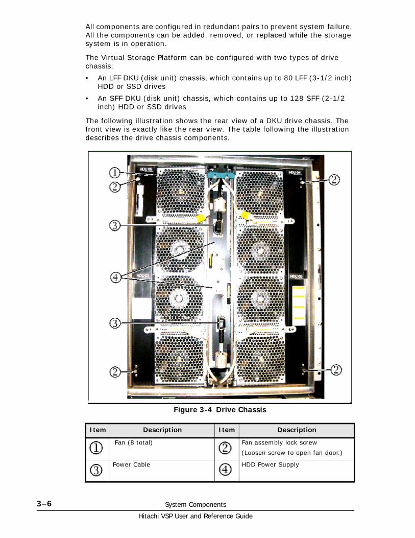
Hitachi VSP User and Reference Guide
3–6 System Components
All components are configured in redundant pairs to prevent system failure. All the components can be added, removed, or replaced while the storage system is in operation.
The Virtual Storage Platform can be configured with two types of drive chassis:
• An LFF DKU (disk unit) chassis, which contains up to 80 LFF (3-1/2 inch) HDD or SSD drives
• An SFF DKU (disk unit) chassis, which contains up to 128 SFF (2-1/2 inch) HDD or SSD drives
The following illustration shows the rear view of a DKU drive chassis. The front view is exactly like the rear view. The table following the illustration describes the drive chassis components.
Figure 3-4 Drive Chassis
Item Description Item Description
Fan (8 total) Fan assembly lock screw
(Loosen screw to open fan door.)
Power Cable HDD Power Supply

System Components 3–7Hitachi VSP User and Reference Guide
The fans on the front of the unit are intake fans that pull ambient air into the unit. The fans on the rear assembly are exhaust fans that blow hot air out of the unit. The two sets of fans work together to create a large airflow through the unit. Either fan assembly is sufficient to cool the unit. Therefore there is no time limit when changing disk drives, as long as either the front or the rear fan assembly is in place.
WARNING: To prevent the unit from overheating, both the front and rear fan assemblies should never be opened at the same time while the system is running.
Figure 3-5 Drive chassis (fan door open)

Hitachi VSP User and Reference Guide
3–8 System Components
As shown in the figure above, the fan assemblies on both the front and rear sides of the drive chassis swing out and away from the unit to allow access to the disk drives. The three-speed fans in the drive chassis are thermostatically controlled by a temperature sensor (thermistor) in the unit. The sensor measures the temperature of the exhaust air from the unit and sets the fan speed as needed to maintain the unit temperature within a preset range. When the unit is not busy and cools down, the fan speed is reduced, saving energy and reducing the noise level of the unit.
When the fan assemblies are opened, the power to the fans is automatically switched off and the fans stop rotating. This helps prevent possible injury because there is no protective screen on the back side of the fans.
Flash componentsThis section includes information on the Hitachi Accelerated Flash storage components, including the flash module, flash box, and flash chassis.
Flash module The flash module (factory designation FMD) is a Hitachi custom-designed and manufactured enterprise class solid state storage module. It uses a high performance, custom ASIC flash controller and standard flash memory chips in an implementation that exceeds the performance of expensive SLC SSDs, but costs less than inexpensive MLC SSDs. The flash module greatly improves the performance and solid state storage capacity of the VSP system, while significantly reducing the cost per TB of storage.
Even in the initial capacity of 1.6 TB, the flash module outperforms both HGST MLC and SLC flash drives, has a longer service life, requires less power per TB, and generates less heat per TB than SSDs. The VSP currently supports both 1.6 TB and 3.2 TB flash modules.
Flash modules can be used instead of or in addition to disk and flash drives, but they are installed in a flash chassis composed of a cluster of four flash boxes. The next section describes the flash box.
Figure 3-6 Flash module

System Components 3–9Hitachi VSP User and Reference Guide
Flash boxA flash box is a 2U high chassis that contains up to 12 flash modules, two redundant power supplies, and two redundant ENC adapters.
Figure 3-7 Flash Box
Item Description Item Description Item Description
Flash module Active LED - lights when flash module is activated. - Blinks at drive access
Flash module Alarm LED - lights when flash module has an error and should be replaced
SAS / ENC Module Power LED
SAS / ENC Module Alarm LED - indicates fatal error condition
SAS / ENC standard IN connector
SAS / ENC high performance IN connector
ENC adapter - connects the flash modules to the BEDs in the controller via ENC cables.
SAS / ENC standard OUT connector
SAS / ENC high performance OUT connector
Power cord receptacle Power Supply - 220 VAC input, draws approximately 265 watts
Power Supply Ready 1 LED - lights when 12 VDC power #1 is ready.
Power Supply Ready 2 LED - lights when 12 VDC power #2 is ready.
Power Supply alarm LED - lights when power supply has an error.

Hitachi VSP User and Reference Guide
3–10 System Components
Flash chassisA flash chassis (factory designation FBX) is a cluster of four flash boxes as shown in the following illustration. It is not an actual chassis or enclosure surrounding the four flash boxes, but since it takes the place of a drive chassis, the cluster is referred to as a chassis for consistency.
The maximum number of flash modules in a flash chassis is 48. The minimum number of flash modules is four, one in each flash box. Flash modules can be added to a flash chassis in increments of four, eight, or 16, depending on the desired RAID configuration, as explained in the next section
Figure 3-8 Flash chassis

System Components 3–11Hitachi VSP User and Reference Guide
Flash configurationsFlash module RAID configurations are similar to drive RAID configurations, but with smaller numbers. The flash chassis holds only 48 drives, while the drive chassis holds either 80 LFF or 128 SFF drives.
Each flash box is divided into two logical units. The LUs are numbered vertically in the FBX starting with the lower logical units and then the upper logical units. The FMDs are numbered 0 through 5 in each logical unit. The following figure shows the numbering sequence.
Figure 3-9 Flash configurations

Hitachi VSP User and Reference Guide
3–12 System Components
Flash RAID configurationsAs described in the previous section, RAID configurations with FMDs are similar to RAID configurations for disk or flash drives. When configuring RAID groups, consider the cluster of four flash boxes in the FBX as a set.
Just as the RAID group number is determined according to the location of a disk drive, the RAID group number is also determined by the location of a flash module in a flash chassis, even though the number of FMDs is smaller than the number of drives in a drive chassis. This is because the VSP is capable of variable numbers of drives in a drive chassis. The following illustration shows two samples of RAID configurations with flash modules.
Figure 3-10 Flash RAID configurations

System Components 3–13Hitachi VSP User and Reference Guide
Cache memoryThe Virtual Storage Platform can be configured with up to 256 GB of cache memory per controller chassis (512 GB for a two-module system). Each controller chassis can contain from two to eight cache memory adapter boards. Each board contains from 8 GB to 32 GB.
Cache memory adapter boards are installed in pairs and work together to provide cache and shared memory for the system. Each pair is called a cluster. From one to four cache clusters can be installed in a controller chassis. In addition to the memory on the cache boards, 4 GB of cache memory is also located on each Virtual Storage Director (microprocessor) board. See the following illustration.
Figure 3-11 Cache memory
Item Description Item Description
Virtual Storage Director (VSD) (microprocessor)
Includes 4 GB cache
Cache Memory Adapter
8, 16, or 24 GB standard
32 GB optional
1 or 2 16 GB SSD drives
VSD Cluster 0 VSD Cluster 1
Cache cluster 0 Cache cluster 1
Cache cluster 2 Cache cluster 3

Hitachi VSP User and Reference Guide
3–14 System Components
Memory operationThe Virtual Storage Platform places all read and write data in the cache. The amount of fast-write data in cache is dynamically managed by the cache control algorithms to provide the optimum amount of read and write cache, depending on the workload read and write I/O characteristics.
Mainframe hosts can specify special attributes (for example, cache fast write command) to write data (typically sort work data) without write duplexing. This data is not duplexed and is usually given a discard command at the end of the sort, so that the data will not be destaged to the drives.
Data ProtectionThe Virtual Storage Platform is designed so that it cannot lose data or configuration information from the cache if the power fails. The cache is protected from data loss up for up to ten minutes by the cache destage batteries while the data is copied to the cache SSD (flash memory) on the cache boards. This is explained in detail in Battery backup operations on page 4-5.
Shared memoryThe Virtual Storage Platform shared memory is not on a separate memory module as it was in the previous hardware systems. Shared memory resides by default on the first pair of cache boards in controller chassis #0. When you install software features such as Copy-on-Write Snapshot or Universal Replicator, the shared memory usage increases as software features are installed. Shared memory can use up to 48 GB, which is the maximum amount of shared memory available if the cache in the first cache board pair is configured to the maximum of 64 GB.
Depending on how much cache memory is installed, it may be necessary to install more cache memory as more software features are installed in the system. Up to 32 GB can be installed on each cache board. When 32 GB of cache is installed, it is also necessary to install a second SSD (cache flash memory) on the cache board to back up the cache in case of power failure. Each SSD is 16 GB.
In addition to cache, the shared memory on each cache board contains a 1/2 GB cache directory to safeguard write pending data in the cache in the unlikely case of double failure of the shared memory cache area. The cache directory has mapping tables for the VSD LDEVs and the allocated cache slots in each VSD cache partition.

4
Power On/Off Procedures 4–1Hitachi VSP User and Reference Guide
Power On/Off Procedures
This chapter describes the prerequisites and procedures to turn the Hitachi Virtual Storage Platform power on and off. It also describes the procedures to follow in case of a power failure.
□ Safety and environmental information
□ Standby mode
□ Normal Power On/Off procedures
□ Emergency power off/on procedure
□ Battery backup operations

Hitachi VSP User and Reference Guide
4–2 Power On/Off Procedures
Safety and environmental information
Standby modeWhen the storage system power cables are plugged into the PDUs and the PDU breakers are ON, the storage system is in standby mode. When the storage system is in standby mode:
• The Basic Supply (BS) LED on the control panel is ON. This indicates that AC power is applied to the power supplies but DC power is not supplied to the rest of the system, except as noted below.
• The READY LED is OFF. This indicates that the controller and drive chassis are not operational.
• The fans in both the controller and drive chassis are running.
• The cache destage batteries are being charged.
• The storage system consumes significantly less power than it does in operating mode. For example, a storage system that draws 100 amps while operating draws only about 70 amps in standby mode. See Table A-2 VSP electrical specifications. single phase current on page A-3 and Table A-3 VSP Electrical specifications. three phase current on page A-4 for power consumption specifications.
To put the storage system into standby mode from the OFF condition:
1. Ensure that power is available to the AC input boxes and PDUs in all racks in which the VSP storage system is installed.
2. Turn all PDU power switches/breakers ON.
To put the storage system into standby mode from a power on condition, complete the steps in Power Off procedures on page 4-4.
To completely power down the storage system, complete the power off procedures in this chapter, then turn off all PDU circuit breakers.
Caution: Before operating or working on the VSP storage system, read the safety section in the Hitachi Virtual Storage Platform Installation Planning Guide and the environmental information in Regulatory Compliance on page C-1.
WARNING: Make certain that the storage system is powered off normally and in standby mode before turning off the PDU circuit breakers. Otherwise, turning off the PDU circuit breakers can leave the storage system in an abnormal condition.

Power On/Off Procedures 4–3Hitachi VSP User and Reference Guide
Normal Power On/Off proceduresThis section provides general information about power on/off procedures for the VSP storage system. If needed, call technical support for assistance.
Power On proceduresPrerequisites:
• Ensure that the storage system is in standby mode. See Standby mode on page 4-2.
Follow this procedure exactly when powering the storage system on. Refer to the illustration of the control panel as needed.
1. On the control panel, check the amber BS LED and make sure it is lit. It indicates that the storage system is in standby mode.
2. In the PS area on the control panel, move the ENABLE switch to the ENABLED position and hold it there. While holding the switch in the ENABLED position, move the PS ON/OFF switch to the ON position. Then release both switches.
3. Wait for the storage system to complete its power-on self-test and boot-up processes. Depending on the storage system configuration, this may take several minutes.
4. When the READY LED is ON, the storage system boot up operations are complete and the storage system is ready for use.
Note: The control panel includes a safety feature to prevent the storage system power from accidentally being turned on or off. The PS power ON/OFF switch does not work unless the ENABLE switch is moved to and held in the ENABLE position while the power switch is moved to the ON or OFF positions.
Note: If SATA drives are installed, the storage system will not go to the READY state until the cache destage batteries are charged to at least 50%. This could take up to 90 minutes if the batteries are completely discharged. The storage system generates a SIM that provides the status of the battery charge. See Cache destage batteries on page 4-6 for information about the batteries.
Note: If the ALARM LED is also on, or if the READY LED is not ON after 20 minutes, contact Technical Support for assistance.

Hitachi VSP User and Reference Guide
4–4 Power On/Off Procedures
Power Off proceduresPrerequisites:
• Ensure that all software-specific shutdown procedures have been completed. Refer to the applicable user manuals for details
• Ensure that all I/O activity to the storage system has stopped. You can vary paths offline and shut down the attached hosts.
Follow this procedure exactly when powering the storage system off.
1. In the PS area on the control panel, move the ENABLE switch to the ENABLED position and hold it there. While holding the switch in the ENABLED position, move the PS ON/OFF switch to the OFF position. Then release both switches.
2. Wait for the storage system to complete its shutdown routines. Depending on the storage system configuration and certain MODE settings, it can take up to 20 minutes for the storage system to copy data from cache to the disk drives and for the disk drives to spin down.
Emergency power off/on procedureThis section describes the procedures to follow to shut down the system in case of emergency and how to bring the system back up after an emergency shutdown.
Emergency power off procedureThe VSP storage system does not have an emergency power off switch as the USP V/VM storage system does.
To shut the system down in an emergency, power off the controllers first, then the drive units, as follows.
1. Open the back doors of both racks that contain control units.a. Turn off the circuit breakers in both lower PDUs in both racks.b. Turn off the circuit breakers in both upper PDUs in both racks with
control units.
2. Open the back doors of all racks that contain only drive units and turn the circuit breakers off in all the PDUs in any order in those racks.
Note: The control panel includes a safety feature to prevent the storage system power from accidentally being turned on or off. The PS power ON/OFF switch does not work unless the ENABLE switch is moved to and held in the ENABLE position while the power switch is moved to the ON or OFF positions.
Note: If the READY and PS LEDs do not turn OFF after 20 minutes, contact the support center for assistance.
Note: Quick Procedure
Controllers: Power PDUs off first. Power PDUs on last.
Drives: Power PDUs off last. Power PDUs on first.

Power On/Off Procedures 4–5Hitachi VSP User and Reference Guide
Power on procedure after emergency power offTo power up the VSP storage system after emergency shutdown, reverse the emergency power off procedure.
1. In all system racks, turn on the circuit breakers in the PDUs that power the drive units.
2. In both controller racks, turn on the circuit breakers in the PDUs that power the controllers.
3. Follow the instructions in Normal Power On/Off procedures on page 4-3.
Battery backup operationsThe Virtual Storage Platform is designed so that it cannot lose data or configuration information if the power fails. The battery system is designed to provide enough power to completely destage all data in the cache if two consecutive power failures occur and the batteries are fully charged. If the batteries do not contain enough charge to provide sufficient time to destage the cache when a power failure occurs, the cache operates in write through mode. This synchronously writes to HDDs to prevent slow data throughput in the cache. When the battery charge is 50% or more, the cache write protect mode operates normally.
When a power failure occurs and continues for 20 milliseconds or less, the storage system continues normal operation. If the power failure exceeds 20 milliseconds, the storage system uses power from the batteries to back up the cache memory data and storage system configuration data to the cache flash memory on each cache board. This continues for up to ten minutes. The flash memory does not require power to retain the data.
The following illustration shows the timing in the event of a power failure.
Figure 4-1 Battery Backup Operations
Item Description Item Description
Power failure occurs The storage system continues to operate for 20 milliseconds and detects the power failure.
The cache memory data and the storage system configuration are backed up to the cache flash memory on the cache boards. The backup continues even if power is restored during the backup.
Unrestricted data backup. Data is continuously backed up to the cache flash memory.

Hitachi VSP User and Reference Guide
4–6 Power On/Off Procedures
Cache destage batteriesThe environmentally friendly nickel hydride cache destage batteries are used to save storage system configuration and data in the cache in the event of a power failure. The batteries are located on the cache memory boards and are fully charged at the distribution center where the storage system is assembled and tested. Before the system is shipped to a customer site, the batteries are disconnected by a jumper on the cache board. This prevents them from discharging during shipping and storage until the system is installed. At that time, an authorized support person connects the batteries.
Battery life
The batteries have a lifespan of two years, and will hold a charge for that time when disconnected. When the batteries are connected and power is on, they are charged continuously. This occurs during both normal system operation and while the system is in standby mode.
When the batteries are connected and the power is off, the batteries slowly discharge. They will have a charge of less than 50% after two weeks without power. When fully discharged, the batteries must be connected to power for three hours to fully recharge.
Long Term Array StorageWhile connected, the cache destage batteries will completely discharge in two to three weeks without power applied. If you do not use a Virtual Storage Platform for two weeks or more, ask technical support to move the batteries to a storage system that is being used, or turn the storage system on to standby mode for at least 3 hours once every two weeks.
If you store the system for more than two weeks and do not disconnect the cache destage batteries, when you restart the system, the batteries will need to charge for at least 90 minutes before the cache will be protected. To prevent the batteries from discharging during long term storage, call technical support and ask them to disconnect the battery jumpers on the cache boards.
Note: The storage system generates a SIM when the cache destage batteries are not connected.
Note: The storage system generates a SIM when the cache destage batteries are not charged to at least 50%. The LEDs on the front panel of the cache boards also show the status of the batteries.

5
Troubleshooting 5–1Hitachi VSP User and Reference Guide
Troubleshooting
This chapter provides troubleshooting information for the Hitachi Virtual Storage Platform storage system.
□ Getting help
□ Solving problems
□ Service Information Messages

Hitachi VSP User and Reference Guide
5–2 Troubleshooting
Getting helpIf you have difficulty with any of the procedures included in this chapter, or if a procedure does not provide the answer or results you expect, contact Hitachi Data Systems support. See Getting help on page Preface-xi in the preface of this manual.
Solving problemsThe Hitachi Virtual Storage Platform storage system is highly reliable and is not expected to fail in any way that would prevent access to user data. The READY LED on the control panel must be ON when the storage system is operating online.
The following table lists possible error conditions and provides recommended actions to resolve each condition. If you are unable to resolve an error condition, contact your Hitachi Data Systems representative, or contact Hitachi Data Systems Technical Support for assistance.
Table 5-1 Troubleshooting
Service Information MessagesThe Virtual Storage Platform generates SIMs to identify normal operations. For example, TrueCopy pair status change) as well as service requirements and errors or failures. For assistance with SIMs, call the support center.
SIMs can be generated by the front-end directors and back-end directors and by the SVP. All SIMs generated by the VSP are stored on the SVP for use by Hitachi Data Systems personnel, logged in the SYS1.LOGREC dataset of the mainframe host system, displayed by the Storage Navigator software, and reported over SNMP to the open-system host. The SIM
Error Condition Recommended Action
Error message displayed.
Determine the type of error (refer to the SIM codes section. If possible, remove the cause of the error. If you cannot correct the error condition, call the support center for assistance.
General power failure
Turn off all PDU switches and breakers. After the facility power comes back on steady, turn them back on and power the system up. See Chapter 4 for instructions. If needed, call Hitachi Data Systems support for assistance.
Fence message is displayed on the console.
Determine if there is a failed storage path. If so, toggle the RESTART switch, and retry the operation. If the fence message is displayed again, call the support center for assistance.
READY LED does not go on, or there is no power supplied.
Call the support center for assistance. WARNING: Do not open the Virtual Storage Platform control frame /controller or touch any of the controls.
ALARM LED is on. If there is a temperature problem in the area, power down the storage system, lower the room temperature to the specified operating range, and power on the storage system. Call the support center if needed for assistance with power off/on operations. If the area temperature is not the cause of the alarm, call the support center for assistance.

Troubleshooting 5–3Hitachi VSP User and Reference Guide
display on Storage Navigator enables users to remotely view the SIMs reported by the attached storage systems. Each time a SIM is generated, the amber Message LED on the control panel turns on. The Hi-Track remote maintenance tool also reports all SIMs to the support center
SIMs are classified according to severity. There are four levels: service, moderate, serious, or acute. The service and moderate SIMs (lowest severity) do not require immediate attention and are addressed during routine maintenance. The serious and acute SIMs (highest severity) are reported to the mainframe hosts once every eight hours.
The following figure illustrates a typical 32-byte SIM from the VSP storage system. SIMs are displayed by reference code (RC) and severity. The six-digit RC, which is composed of bytes 22, 23, and 13, identifies the possible error and determines the severity. The SIM type, located in byte 28, indicates which component experienced the error.
Note: If a serious or acute-level SIM is reported, call the support center immediately to ensure that the problem is being addressed.
Figure 5-1 Service Information Message

Hitachi VSP User and Reference Guide
5–4 Troubleshooting

A
Specifications A–1Hitachi VSP User and Reference Guide
Specifications
This appendix provides the mechanical, electrical, and environmental specifications for the Hitachi Virtual Storage Platform storage system.
□ Mechanical specifications
□ Electrical specifications
□ Environmental specifications
□ Equipment noise
□ Heat output and air flow
□ PDU specifications

Hitachi VSP User and Reference Guide
A–2 Specifications
Mechanical specificationsThe following table lists the mechanical specifications of the VSP storage system.
Table A-1 VSP mechanical specifications
Electrical specificationsThe VSP storage system can use single phase or three phase AC power for both open and mainframe systems.
• Table A-2 VSP electrical specifications. single phase current on page A-3 lists the single phase specifications.
• Table A-3 VSP Electrical specifications. three phase current on page A-4 lists the three phase power requirements.
• Table A-5 PDU plugs, circuit breakers, and receptacles1 on page A-5 lists the PDU specifications for both single phase and three phase power.
Note: The weight and electrical specifications in the following tables were taken from a VSP storage system in a controlled environment. To calculate the weight and current draw of a specific system, use the Power and Weight calculator at
http://www.hds.com/go/weight-and-power-calculator/
Contact technical support if you need assistance using this tool.
Dimension Single Rack Single Module (3 racks)
Dual Module (6 racks)
Width (inches / mm) 24.0 / 610 71.3 / 1810 142.1 / 3610
Depth (inches / mm) 43.3 / 1100 43.3 / 1100 43.3 / 1100
Height (inches / mm) 73.1 / 2005 73.1 / 2005 73.1 / 2005
System
Weight
Min (lbs / kg) 767 / 346 (Diskless) 3610 / 1628 7503 / 3384
Max (lbs / kg) 862 / 389 4592 / 2071 9784 / 4413
Rack Weight
(lbs / kg) 292.6 / 133 Rack Weight is included in system weight

Specifications A–3Hitachi VSP User and Reference Guide
Table A-2 VSP electrical specifications. single phase current
Item Unit Specification
Power requirements, system operating
.
Maximum total power consumption for a two module system during normal operation is 98 amps.
-
Maximum total power consumption for a fully configured two module system (2048 disk drives) with all drives in write mode is 112 amps.
AC, single phase
2 pole + ground
200 V to 240 V, +6% -8%
50 Hz ±3 Hz, 60 Hz ± 2 Hz
Drive chassis
(240 HDD)
4.3KVA (2.5" SAS)
5.7KVA (3.5” SATA)
Maximum 41.4 KVA
Controller chassis power supply
Input Current 7.18 A
Steady Current 3.59 A
Leakage Current 0.28 mA
Inrush current 1st (0-p) 20 A
2nd (0-p) 15A
1st (0-p) Time
(-25%: 80 ms
Drive chassis
power supply
Input Current 6.52 A
Steady Current 3.26A
Leakage Current 0.28 mA
Inrush current 1st (0-p) 20 A
2nd (0-p) 15A
1st (0-p) Time
(-25%: 80 ms
Power consumption, system in standby
-
Maximum total power consumption for a two module system in standby mode is 75 amps.
Control chassis 0.79 KVA
Drive chassis 1.34 KVA
Rack with one control chassis and two drive chassis
3.47 KVA
Rack with three drive chassis
4.02 KVA
Single module (3 rack system)
11.51 KVA
Dual module (6 rack system)
23.02 KVA / 75 A

Hitachi VSP User and Reference Guide
A–4 Specifications
Table A-3 VSP Electrical specifications. three phase current
Table A-4 Power consumption, single phase current (HDDs)
Item Unit Specification
Power requirements AC, 3 Phase delta 208 V +5/-15%, 50/60 Hz
Power consumption
.
NOTE: The power consumption of the system is the same whether it uses single phase or three phase power. The difference is that each branch of the three phase input power draws less current than the single phase conductors.
Drive chassis
(240 HDD)
4.3KVA (2.5" SAS)
5.7KVA (3.5” SATA)
Maximum 41.4 KVA
Controller chassis power supply
Input Current 7.18 A
Steady Current 3.59 A
Leakage Current 0.28 mA
Inrush current 1st (0-p) 20 A
2nd (0-p)
1st (0-p) Time
(-25%: 80 ms
Drive chassis
power supply
Input Current 6.52 A
Steady Current 3.26A
Leakage Current 0.28 mA
Inrush current 1st (0-p) 20 A
2nd (0-p)
1st (0-p) Time
(-25%: 80 ms
Configuration1 Idle2 Max Power
Consumption3, 5
Current per rack Current per rack
R00 (module 0 controller4 17.3 19.6
R10 (module 1 controller4 18.2 17.9
R01 (module 0 drive 1)4 14.8 18.3
R11 (module 1 drive 1)4 16.1 19.6
R02 (module 0 drive 2)4 17.2 17.1
R12 (module 1 drive 2)4 14.4 18.6
Total Power 98 111.1
Notes:
1. The numbers in this table were provided by measuring system power consumption in a controlled environment. Depending on the air temperature and actual voltage where the system is installed, current draw can vary as much as + or - 10%. To calculate power draw for a specific system, use the Power and Weight calculator at. http://www.hds.com/go/weight-and-power-calculator/ Contact technical support if you need assistance using this tool.
2. Idle condition - system is powered on but not being accessed.
2. Max power consumption - all disks are in write mode.
3. R00 and R01 are controller racks with one controller chassis and two drive chassis.
4. R01, R02, R11, and R12 are drive racks with three drive chassis each.
5. Configured with the maximum of 2048 146 GB SAS drives.

Specifications A–5Hitachi VSP User and Reference Guide
Table A-5 PDU plugs, circuit breakers, and receptacles1
Figure A-1 Rack numbers
Phase Location PDU PlugMax
Voltage Rating
Max Current Rating
No. of CB per PDU
Breaker Rating
Power Supply Receptacle IEC
C14 2
Single Americas (except Brazil)
NEMA L6 30P twistlock2 pole, 3 wireA + B + gnd
208 V 30 Aper PDU
2 16 A,20 A trip
2 pole, 3 wire220 VACA + B + gnd
EMEA / APAC/Brazil
IEC 309, blue 2 pole, 3 wireA + B + gnd
230 V 32 Aper PDU
2 16 A,20 A trip
2 pole, 3 wire220 VACA + B + gnd
Three Americas including Brazil
NEMA L15 30P twistlock 3 pole, 4 wireA + B + C + gnd
208 V 30 A perphase
3 UL489 15 A2 pole
2 pole, 3 wire220 VACA-B or B-C + gnd
APAC/EMEA
IEC 309, red4 pole, 5 wireA + B + C + Neut+ gnd
400 V 32 A perphase
6 16 A2 pole
1 pole, 3 wire200 VACA-N or B-N orC-N + gnd
Required number of plugs in each PDU per chassis
Controller chassis Drive chassis Same power cord and plug for all power supplies.
4 4
Required number of PDUs per rack Controller rack Drive rack Same power cord and plug for all PDPs.
2 if only controller installed4 if controller and drive chassis
4
NOTES:
1. The numbers in this table were taken from the PDU manufacturer’s specifications. See the manufacturers specifications at the end of this appendix.
2. This information shows how the receptacles is wired inside the PDU. The equivalent IEC plug for this receptacle is IEC 13.

Hitachi VSP User and Reference Guide
A–6 Specifications
Environmental specificationsThe following table lists the environmental specifications of the VSP storage system.
Table A-6 Virtual Storage Platform Environmental specifications
Item Operating Not Operating In Storage
Temperature (ºF / ºC)
60.8 - 89.6 /16 to 32
-18 to 109.4 / -10 to 43 -18 to 95 /-10 to 35 11
-45 - 140-25 to 60
Relative Humidity(%)4
20 to 80 8 to 90 5 to 95
Max. Wet Bulb (ºF / ºC)
78.8 / 26 80.6 / 27 84.2 / 29
TemperatureDeviationper hour) (ºF / ºC)
18 / 10 18 / 10 36 / 20
Vibrationto 10Hz: 0.25 mm
10 to 300 Hz0.49 m/s2
5 to 10 Hz: 2.5 mm 10 to 70 Hz: 4.9 m/s2
70 to 99 Hz: 0.05 mm99 to 300 Hz: 9.8 m/s2
Sine Vibration: 4.9 m/s2, 5 min.At the resonant frequency with the highest displacement found between 3 to 100 Hz 6
Random Vibration:0.147 m2/s330 min, 5 to 100 Hz 7
Earthquakeresistance (m/s2)
Up to 2.5 10 - -
Shock - 78.4 m/s2, 15 ms Horizontal:Incline Impact 1.22 m/s8
Vertical:Rotational Edge 0.15 m9
Altitude -60 m to 3,000 m -
Notes:
1. Environmental specification for operating condition should be satisfied before the storage system is powered on. Maximum temperature of 32°C should be strictly satisfied at air inlet portion.
2. Recommended temperature range is 21 to 24°C
3. Non-operating condition includes both packing and unpacking conditions unless otherwise specified.
4. On shipping/storage condition, the product should be packed with factory packing
5. No condensation in and around the drive should be observed under any conditions. No condensation in and around the drive should be observed under any conditions.
6. The above specifications of vibration are applied to all three axes
7. See ASTM D999-01 The Methods for Vibration Testing of Shipping Containers.
8. See ASTM D5277-92 Test Method for Performing Programmed Horizontal Impacts Using an Inclined Impact Tester.
9. See ASTM D6055-96 Test Methods for Mechanical Handling of Unitized Loads and Large Shipping Cases and Crates.
10. Time is 5 seconds or less in case of the testing with device resonance point (6 to 7Hz.
11. When flash modules are installed in the system

Specifications A–7Hitachi VSP User and Reference Guide
Equipment noiseThe acoustic emission values [loudness in dB (A)] for the VSP storage system storage system are:
• Front/rear = 65 dB (A)
• Both sides = 65 dB (A)
Heat output and air flowThe following table lists the heat output and air flow requirements for the VSP storage system components.
Both the control chassis and the disk chassis contain front and rear fans to circulate air through the chassis from front to back. Air flows in through the front bezel to the rear of the component and exits through the perforations in the rear door. Either the front fans or the rear fans can cool the chassis by themselves. The racks do not contain fans. Airflow is from front to back.
Table A-7 VSP Heat, Power, and airflow
Model Number Heat Output (kW)
Power Consumption
(kVA)
Air Flow cubic ft / cubic meters/min)
DKC710I-CBX 0.4751 0.500 1 247.2 / 7.0
DKC-F710I-SBX 0.5701 0.6001 317.8 / 9.0
DKC-F710I-UBX 0.5701 0.6001 317.8 / 9.0
DKC-F710I-SVP 0.052 0.055 -
DKC-F710I-HUB 0.010 0.010 -
DKC-F710I-16MFS 0.118 0.124 -
DKC-F710I-16MFL 0.118 0.124 -
DKC-F710I-8UFC 0.072 0.076 -
DKC-F710I-16UFC 0.072 0.076 -
DKC-F710I-16MUS 0.118 0.124 -
DKC-F710I-16MUL 0.118 0.124 -
DKC-F710I-SCA 0.080 0.084 -
DKC-F710I-CPC 0.068 0.072 -
DKC-F710I-C16G 0.019 0.020 -
DKC-F710I-BM64 0.005 0.0052 -
DKC-F710I-MP 0.190 0.200 -
DKC-F710I-ESW 0.070 0.074 -
DKC-F710I-146KCM 0.013 0.014 -
DKC-F710I-300JCM 0.013 0.014 -
DKC-F710I-500HCM 0.013 0.014 -
DKC-F710I-600JCM 0.013 0.014 -
DKC-F710I-2R0H2M 0.020 0.021 -

Hitachi VSP User and Reference Guide
A–8 Specifications
PDU specificationsThis section contains the manufacturers specifications and diagrams for the single and three-phase PDUs used by the VSP storage system.
DKC-F710I-200SAM 0.010 0.011 -
DKC-F710I-400S1M 0.010 0.011 -
DKC-F710I-1R6FM3 0.017 18 watts -
DKC-F710I-3R2FM 0.018 19 watts -
Notes:
1: Maximum values when all fans rotate at maximum speed.
2: Power is consumed during the battery back-up time only.
3. Flash module drive. Estimated power consumption for a 12-drive FMU is 531 watts, including the ENCs and power supplies.
Model Number Heat Output (kW)
Power Consumption
(kVA)
Air Flow cubic ft / cubic meters/min)

Specifications A–9Hitachi VSP User and Reference Guide
Single Phase PDU
1 1
2 2
3 3
4 4
5 5
6 6
7 7
8 8
AA
BB
CC
DD
DW
G N
O:
RE
V
SH
EE
T:O
F
DR
AW
N
CH
ECK
ED &
AP
P.
TITL
E
DR
AWIN
G N
OT
TO S
CA
LE
PAR
T N
UM
BER
:
QTY
PER
UN
IT:
1M
ATE
RIA
L TY
PE:
MAT
ERIA
L G
AUG
E:
FIN
ISH
:
GR
EA
T LA
KE
S C
AS
E &
CA
BIN
ET
CO
., IN
C.
P.O
. BO
X 5
51 E
DIN
BOR
O, P
A 1
6412
PH
ON
E (8
14) 7
34-7
303
FAX
(814
) 734
-390
7E-
MA
IL g
lcc@
grea
tcab
inet
s.co
m
Use
of t
his
docu
men
t is
subj
ect t
oa
conf
iden
tialit
y an
d no
ndis
clos
ure
agre
emen
t with
Gre
at L
akes
Cas
e&
Cab
inet
Co.
, Inc
. (G
LCC
) and
may
not b
e re
prod
uced
, dis
clos
ed o
rut
ilize
d in
who
le o
r in
part
with
out
prio
r writ
ten
auth
oriz
atio
n fro
m G
LCC
.
NO
TIC
E:
TOLE
RA
NC
E U
NLE
SS O
THER
WIS
E N
OTE
D:
ANG
ULA
R +
/- 1�
.XX
XX
+/-
.010
.XX
X +
/- .0
15.X
X +
/- .0
30 .X
FO
R R
EF. O
NLY
UN
LESS
OTH
ERW
ISE
SPEC
IFIE
DA
LL D
IME
NSI
ON
S A
RE
IN IN
CH
ES
DIM
ENS
ION
AL
LIM
ITS
AP
PLY
AFT
ER A
PPL
ICAT
ION
OF
FIN
ISH
INTE
RP
RE
T D
RA
WIN
G P
ER
ASM
E Y
14.5
M-1
994
THIR
D A
NG
LEP
RO
JEC
TIO
N
DAT
E
DAT
E1
1
--
-
- - -
P
S14
65B
PD
U W
ITH
L6-
30P
Great�Lakes�Case�&�Cab
inet�Co.,�Inc.
Part
�#�P
S146
5B� 1.
������
�Shi
ppin
g���p
leas
e�en
sure
�(1)�u
nits
�per
�box
2.���
����B
ox�L
abel
s���E
ach�
box�
to�h
ave�
one�
labe
l�tha
t�disp
lays
�the
������
����S
eria
l�Num
ber�o
f�the
�uni
t�ins
ide.
3.���
����L
abel
s�on�
PDU
����E
TL�a
nd�S
eria
l�num
ber�l
abel
s4.
������
�Mou
ntin
g�br
acke
ts���
One
�set�o
f�Uni
vers
al�b
rack
ets�p
er�u
nit
5.���
����P
lug�
Reta
iner
�Clip
s���Y
es�(b
uilt�
in)�(
12�x
�C13
R�L)
6.���
����C
ord�
Colo
r���B
lack
7.���
����C
ord�
Leng
th���
10'
8.���
����P
lug�
Colo
r���B
lack
9.���
����P
lug�
Type
���L6
�30P
�(IP2
0)�(3
wire
���2p
ole)
10.��
��Cas
e�Co
lor��
�Alu
min
um�
11.��
���Am
pera
ge���
30�A
mps
12.��
���Vo
ltage
���20
8V13
.�����
Dim
ensio
ns�2
6.82
”�x�
3.25
”�x�
1.72
”14
.�����
Circ
uit�b
reak
er�sp
ecifi
catio
ns���
UL4
8915
.�����
Phas
e���S
ingl
e�(1
)
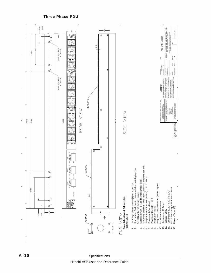
Hitachi VSP User and Reference Guide
A–10 Specifications
Three Phase PDU
23
45
67
8
ABCD
DW
G N
O:
RE
V
SH
EE
T:O
F
DR
AW
N
CH
ECK
ED &
AP
P.
TITL
E
DR
AWIN
G N
OT
TO S
CA
LE
PAR
T N
UM
BER
:
QTY
PER
UN
IT:
1M
ATE
RIA
L TY
PE:
MAT
ERIA
L G
AUG
E:
FIN
ISH
:
GR
EA
T LA
KE
S C
AS
E &
CA
BIN
ET
CO
., IN
C.
P.O
. BO
X 5
51 E
DIN
BOR
O, P
A 1
6412
PH
ON
E (8
14) 7
34-7
303
FAX
(814
) 734
-390
7E-
MA
IL g
lcc@
grea
tcab
inet
s.co
m
Use
of t
his
docu
men
t is
subj
ect t
oa
conf
iden
tialit
y an
d no
ndis
clos
ure
agre
emen
t with
Gre
at L
akes
Cas
e&
Cab
inet
Co.
, Inc
. (G
LCC
) and
may
not b
e re
prod
uced
, dis
clos
ed o
rut
ilize
d in
who
le o
r in
part
with
out
prio
r writ
ten
auth
oriz
atio
n fro
m G
LCC
.
NO
TIC
E:
TOLE
RA
NC
E U
NLE
SS O
THER
WIS
E N
OTE
D:
ANG
ULA
R +
/- 1�
.XX
XX
+/-
.010
.XX
X +
/- .0
15.X
X +
/- .0
30 .X
FO
R R
EF. O
NLY
UN
LESS
OTH
ERW
ISE
SPEC
IFIE
DA
LL D
IME
NSI
ON
S A
RE
IN IN
CH
ES
DIM
ENS
ION
AL
LIM
ITS
AP
PLY
AFT
ER A
PPL
ICAT
ION
OF
FIN
ISH
INTE
RP
RE
T D
RA
WIN
G P
ER
ASM
E Y
14.5
M-1
994
THIR
D A
NG
LEP
RO
JEC
TIO
N
DAT
E
DAT
E1
1
--
-
- - -
P
S14
74B
PD
U W
ITH
L15
-30P
Great�Lakes�Case�&�Cab
inets�Inc.
Part
�#�P
S147
4B� 1.
������
�Shi
ppin
g���p
leas
e�en
sure
�(1)�u
nits
�per
�box
2.���
����B
ox�L
abel
s���E
ach�
box�
to�h
ave�
one�
labe
l�tha
t�disp
lays
�the
������
����S
eria
l�Num
ber�o
f�the
�uni
t�ins
ide.
3.���
����L
abel
s�on�
PDU
����E
TL�a
nd�S
eria
l�num
ber�l
abel
s�4.
������
�Mou
ntin
g�br
acke
ts���
One
�set�o
f�Uni
vers
al�b
rack
ets�p
er�u
n it
5.���
����P
lug�
Reta
iner
�Clip
s���Y
es�(b
uilt�
in)�(
12�x
�C13
R�L)
6.���
���� P
ower
cor
d�Col
or���
Blac
k7.
������
�Pow
er c
ord�
Leng
th���
�10
ft8.
������
�Plu
g�Co
lor��
�Bla
ck9.
������
�Plu
g�Ty
pe���
L15�
30P�
(IP20
)�(4w
ire���
3pol
e)10
.����C
ase�
Colo
r���A
lum
inum
�11
.�����
Ampe
rage
���30
�Am
ps12
.�����
Volta
ge���
208V
13.��
���Di
men
sions
�30.
57”�
x�3.
25”�
x�1.
72”
14.��
��Circ
uit�b
reak
er�sp
ecifi
catio
ns���
UL4
8915
.����P
hase
����T
hree
��(3)

B
Comparing Universal Storage Platform V/VM and Virtual Storage Platform B–1Hitachi VSP User and Reference Guide
Comparing Universal Storage PlatformV/VM and Virtual Storage Platform
This appendix provides a comparison of the main features of Universal Storage Platform V/VM storage system and the Hitachi Virtual Storage Platform storage system.
□ Comparison of USP V/VM and VSP

Hitachi VSP User and Reference Guide
B–2 Comparing Universal Storage Platform V/VM and Virtual Storage Platform
Comparison of USP V/VM and VSPThe Hitachi Virtual Storage Platform includes several upgrades from the Universal Storage Platform V/VM as well as a number of new features. these include:
• High scalability. The system supports configurations of 2-1/2 and 3-1/2 inch disk drives in either a single or dual controller configuration
• Shared processors. In the Virtual Storage Platform, the processor and interface cards are separate. this allows either or both to be configured separately, and allows each processor to share resources across multiple interface cards.
• Load balancing. The VSP storage system allows workloads to be better balanced across management processor and breaks the affinity between specific front-end and back-end ports with specific processors.
• High performance. The system uses shared high performance quad-core processors instead of single-core. this significantly increases system total processing speed and distributes processing across the FEDs and BEDs as needed.
• Faster access to system control information through the use of onboard memory on the virtual storage directors (microprocessors).
• Storage management usability improvements. The new version includes a user-friendly, task-based GUI that reduces the number of operations needed to complete a task and includes wizards to assist users in new or repetitive tasks. this version of Storage Navigator also includes context-sensitive online help.
The following tables show the main differences between the Universal Storage Platform V/VM and the Virtual Storage Platform.
Table B-1 Storage Management Improvements
Table B-2 Basic Functional Differences
Virtual Storage Platform Universal Storage Platform V/VM
Use Case Oriented Operation Architecture Oriented
Fewer steps and clicks Many steps and clicks for operation
Faster operation and higher performance Slow performance impression
Unified User interface (GUI/CLI) Many user interfaces
Feature Virtual Storage Platform Universal Storage Platform V/VM
FlashCopy Version 1 Not supported (Only FC V2) Supported
Drive Emulation Type 3380-3
3390-1/2/3/3R/9/L/M
3380-3
3390-1/2/3/3R/9/L/M
DKC Emulation Type 3990/2105/2107 3990/2105/2107
The number of multi-relations
16 16

Comparing Universal Storage Platform V/VM and Virtual Storage Platform B–3Hitachi VSP User and Reference Guide
Table B-3 Functional Differences - ShadowImage for Mainframe
The maximum relations in system
1048575 1048575
The maximum relations for each 1VOL
1000 1000
External VOL Source: Supported
Target: Supported
Source: Supported (V07 or higher)
Saving Differential Bitmap Save to SVP Save to SVP
Supported OS OS/390 V2/R10 or higher
/OS V1R0 or higher
z/VM V5R3 or higher
z/VSE V4R1 or higher
OS/390 V2/R10 or higher
z/OS V1R0 or higher
z/VM V5R3 or higher
z/VSE V4R1 or higher
Operation Interface TSO
ICKDSF
DFSMSdss
ANTRQS
TSO
ICKDSF
DFSMSdss
ANTRQS
. Feature Virtual Storage Platform
Universal Storage Platform V/VM
Basic Functions
DKC Emulation Type 2105
2107
3990
2105
2107
Drive Emulation Type 3380-3
3390-1/2/3/3R/9/L/M
3380-3
3390-1/2/3/3R/9/L/M
HOST I/F FICON FICON
The biggest size of pair creatable volume.
3390-M 3390-M
Maximum number of pairs in system
16k 16k
Maximum number of CTGs in system
256 256
Maximum number of pairs in one CTG
8192 8192
Saving Differential Bitmap
Save to SSD Save to SVP
Save to SYSTEM DISK
Interface Storage Navigator
PPRC
ShadowImage for Mainframe
Storage Navigator
PPRC
ShadowImage for Mainframe
Expanded Function
Pair configuration 1:11:N (N<=3) 1:11:N (N<=3)
At-Time Split Function Supported Supported
Feature Virtual Storage Platform Universal Storage Platform V/VM

Hitachi VSP User and Reference Guide
B–4 Comparing Universal Storage Platform V/VM and Virtual Storage Platform
Table B-4 Functional Differences - ShadowImage for Open Systems
. Feature Virtual Storage Platform
Universal Storage Platform V/VM
Basic Functions
DKC Emulation Type 2105
2107
3990
2105
2107
Drive Emulation Type Open-3, Open-8,Open-9
Open-E, Open-L, Open-V
Open-3, Open-8,Open-9
Open-E, Open-L, Open-V
Host I/F Fibre Fibre
Maximum size of pair creatable volume.
Open-V 4 TB Open-V 4 TB
Maximum number of pairs in system
16k Pair 16k Pair
Maximum number of CTG in system
256CTG 256CTG
Maximum number of pair in one CTG
8192 Pair 8192 Pair
Saving differential bitmap
Save to SSD Save to SVPSave to SYSTEM DISK
Operation interface Storage Navigator
Raidmanager (Inband)
Raidmanager (Outband)
Storage Navigator
Raidmanager (Inband)
Expanded Function
Pair configuration 1:1
Cascade pair
1:N (N <= 3)
1:1
Cascade pair
1:N (N <= 3)
At-Time Split Function Supported Supported

C
Regulatory Compliance C–1Hitachi VSP User and Reference Guide
Regulatory Compliance
This appendix includes a comprehensive set of specifications for the Hitachi Virtual Storage Platform storage system described in this manual. The Regulatory Compliance section includes a table of regulatory specifications that are met by the VSP storage system. Following the tables are individual regulatory statements that explain the requirements of various countries.
□ Regulatory compliance
□ US FCC Notice
□ European Declaration of Conformity
□ Notice of export controls
□ Hazardous and toxic substances
□ Disposal
□ Recycling
□ Electronic emissions certificates

Hitachi VSP User and Reference Guide
C–2 Regulatory Compliance
Regulatory complianceThis equipment has been tested and is certified to meet the following standards:
Table C-1 Virtual Storage Platform Certifications
Standard Specification Mark on the product Country
Electronic emission control
FCC Part 15 Subpart B Class A
Yes (FCC) U.S.A
Electronic emission control
FCC Part 15 Subpart B Class A:2010, Class A
ICES-003 Issue 4 Class A
Yes (UL) Japan
Safety certification TUV Safety Report and TUV-NRTL Certification, FCC Verification Report
Yes (TUV) EU, North America
Electronic emission certifications
TUV Safety Report, EMC Report, TUV GS License, EMC Certificate, CE Mark
Yes (CE Mark) European Union
Electronic emission control
CB Report and Certificate
Yes (TUV) Worldwide
Electronic emission control
Test Report for C-Tick Approval
Yes Australia andNew Zealand
VCCI Registration for Product and Accessories
VCCI Class A Yes (VCCI) Japan
Safety certification GOST Certificate for Product and Accessories
Yes (GOST) Russia
Electronic emission control
BSMI Approval for Product and Accessories
Yes (BSMI) Taiwan
Electronic emission control
RRL Approval and KTL Safety Approval
Yes (RRL) Korea
Safety certification IRAM Approval Yes Argentina
Electronic emission control
CCC Approval for Switching Power Supply
Yes (IRAM) China
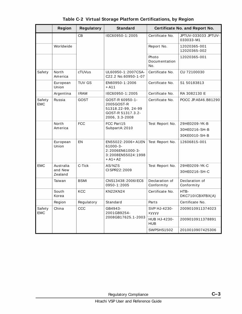
Regulatory Compliance C–3Hitachi VSP User and Reference Guide
Table C-2 Virtual Storage Platform Certifications, by Region
Region Regulatory Standard Certificate No. and Report No.
CB IEC60950-1:2005 Certificate No. JPTUV-033033 JPTUV-033033-M1
Worldwide Report No. 12020365-001 12020365-002
Photo Documentation No.
12020365-001
Safety North America
cTUVus UL60950-1:2007CSA-C22.2 No.60950-1-07
Certificate No. CU 72100030
European Union
TUV GS EN60950-1:2006 +A11
Certificate No. S1 50183813
Argentina IRAM IEC60950-1:2005 Certificate No. RA 3082130 E
Safety EMC
Russia GOST GOST-R 60950-1-2005GOST-R 51318.22-99, 24-99 GOST-R 51317.3.2-2006, 3.3-2008
Certificate No. POCC JP.Aß46.B81290
North America
FCC FCC Part15 SubpartA:2010
Test Report No. 29HE0209-YK-B
30HE0216-SH-B
30KE0010-SH-B
European Union
EN EN55022:2006+A1EN61000-3-2:2006EN61000-3-3:2008EN55024:1998+A1+A2
Test Report No. 12606815-001
EMC Australia and New Zealand
C-Tick AS/NZS CISPR22:2009
Test Report No. 29HE0209-YK-C
30HE0216-SH-C
Taiwan BSMI CNS13438:2006IEC60950-1:2005
Declaration of Conformity
Declaration of Conformity
South Korea
KCC KN22KN24 Certificate No. HTB-DKC710ICBXFBX(A)
Region Regulatory Standard Parts Certificate No.
Safety EMC
China CCC GB4943-2001GB9254-2008GB17625.1-2003
SVP HJ-4230-xyyyy
2009010911374023
HUB HJ-4230-HUB
2009010911378891
SWPSHS1502 2010010907425306

Hitachi VSP User and Reference Guide
C–4 Regulatory Compliance
US FCC NoticeFCC Notice
Federal Communications Commission
This equipment has been tested and found to comply with the limits for a Class A digital device, pursuant to part 15 of the FCC Rules. These limits are designed to provide reasonable protection against harmful interference when the equipment is operated in a commercial environment.
This equipment generates, uses, and can radiate radio frequency energy and, if not installed and used in accordance with the instruction manual, may cause harmful interference to radio communications. Operation of this equipment in a residential area is likely to cause harmful interference, in which case users will be required to correct the interference at their own expense.
Electronic emissions testingEMI testing was done with shielded cables. Therefore, in order to comply with the FCC regulations, you must use shielded cables with your installation.
The EMI tests were done in the following configurations:
DKC710I-CBX+DKC+F710I-SBX
DKC710I-CBX+DKC+F710I-SBX+DKC-F710I-UBX
Copies of the Underwriters Laboratories EMI compliance certificates are located at the end of this chapter.
If trouble occurs in another configuration, a user may be requested to take appropriate preventive measures.
European Declaration of Conformity
"EINE LEICHT ZUGÄNGLICHE TRENN-VORRICHTUNG, MIT EINER KONTAKT-ÖFFNUNGSWEITE VON MINDESTENS 3mm IST IN DER UNMITTELBAREN NÄHE DER VERBRAUCHERANLAGE ANZUORDEN (4-POLIGE ABSCHALTUNG)."
Maschinen lärm informations verordnung 3. GSGV, 18.01.1991: Der "höchste" Schalldruckpegel beträt 70 db (A) oder weniger gemäß ISO
7779
CLASS 1 LASER PRODUCT
Warning This equipment complies with the requirements relating to electromagnetic compatibility, EN 55022 class A for ITE, the essential protection requirement of Council Directive 89/336/EEC on the approximation of the laws of the Member States relating to electromagnetic compatibility.

Regulatory Compliance C–5Hitachi VSP User and Reference Guide
Notice of export controlsExport of technical data contained in this document may require an export license from the United States government and/or the government of Japan. Contact the Hitachi Legal Department for any export compliance questions
Hazardous and toxic substancesTable C-3 Hazardous and toxic substances
Disposal
WARNING: This is a Class A product. In a domestic environment this product may cause radio interference in which case the user may be required to take adequate measures.
WARNING: Dies ist ein Produkt der Klasse A. In nichtgewerblichen Umgebungen können von dem Gerät Funkstörungen ausgehen, zu deren Beseitigung vom Benutzer geeignete Maßnahmen zu ergreifen sind.
This symbol displays requirements for controlling pollution caused by electronic information products.
Toxic and Hazardous Substances and Elements
Unit Lead (PB)
Mercury (Hg)
Cadmium (Cd)
Hexavalent Chronium (Cr (VI))
Polybrominated biphenyls (PBB)
Polybrominated diphenyl ethers (PBDE)
Controller chassis
X O O O O O
Drive chassis
X O O O O O
The Symbol O indicates that this toxic or hazardous substances contained in all of the homogeneous materials for this part is below this limit requirement in SJ/T 11363-2006.
The symbol X indicates that this toxic or hazardous substances contained in at least one of the homogeneous materials used for this part is above the limit requirement in SJ/T 11363-2006.
NOTE: This symbol on the product or on its packaging means that your electrical and electronic equipment should be disposed at the end of life separately from household wastes. There are separate collection systems for recycling EU and many cities in the USA. For more information, contact the local authority or the dealer where you purchased the product.

Hitachi VSP User and Reference Guide
C–6 Regulatory Compliance
Recycling
Electronic emissions certificatesCopies of the Underwriters Laboratories EMI compliance certificates are located on the following pages. Contact Hitachi Data Systems support for detailed information if needed.
.
The cache backup battery unit includes a nickel-hydride battery. A nickel-hydride battery should be recycled when it is no longer usable. When you replace the battery unit, do not dispose of the old one in the trash. recycle the battery instead. The mark posted on the battery unit is a three-arrow mark that means a recyclable part.

Regulatory Compliance C–7Hitachi VSP User and Reference Guide
Figure C-1 UL EMI compliance certificate (1 of 3)

Hitachi VSP User and Reference Guide
C–8 Regulatory Compliance
Figure C-2 UL EMI compliance certificate (2 of 3)

Regulatory Compliance C–9Hitachi VSP User and Reference Guide
Figure C-3 UL IMI compliance certificate (1 of 3)

Hitachi VSP User and Reference Guide
C–10 Regulatory Compliance

CA KD E F G H I J L M N O P Q R S T U V W X Y# B ZA B C D F G J K L M P R S T V
Glossary–1Hitachi VSP User and Reference Guide
Glossary
This glossary defines the special terms used in this document.
A
ATA
Advanced Technology Attachment. This is a disk drive implementation that integrates the controller on the disk drive.
array
See disk array.
B
back-end director (BED)
The hardware component that controls the transfer of data between the drives and cache. A BED feature consists of a pair of boards. A BED is also referred to as a disk adapter (DKA).
BED
See back-end director.
BS
basic (power) supply
C
CCI
Command Control Interface
CHA
See channel adapter.

CA KD E F G H I J L M N O P Q R S T U V W X Y# B ZA B C D F G J K L M P R S T V
Hitachi VSP User and Reference Guide
Glossary–2
controller chassis
The hardware assembly that contains the logic and processing components of the Virtual Storage Platform, including the front-end directors, virtual storage directors, cache memory, switches, and back-end directors. The Virtual Storage Platform storage system can be configured with one or two control chassis.
D
disk array
Disk array, or just array, is a complete storage system, including the control and logic devices, storage devices (HDD, SSD), connecting cables, and racks.
drive chassis
The hardware component of the Virtual Storage Platform that houses disk drives and/or flash drives. The Virtual Storage Platform can be configured with up to 16 drive chassis.
dynamic provisioning
An approach to managing storage. Instead of “reserving” a fixed amount of storage, it removes capacity from the available pool when data is actually written to disk. Also called thin provisioning.
F
FED
See front-end director.
FBX
See flash chassis.
FMD
See flash module.
FICON
Fibre Connectivity
flash chassis
A cluster of four flash boxes that contain up to 48 flash drives and fit in the space of a DKU drive chassis. The factory designation is FBX.
flash drive
A data drive that is a solid-state memory device instead of a rotating hard disk.

CA KD E F G H I J L M N O P Q R S T U V W X Y# B ZA B C D F G J K L M P R S T V
Glossary–3Hitachi VSP User and Reference Guide
flash module
A flash module (FMD) is a Hitachi custom-designed and manufactured enterprise class solid state storage module. It uses a high performance, custom ASIC flash controller and standard flash memory chips in an implementation that exceeds the performance of expensive SLC SSDs, but costs less than less expensive MLC SSDs.
free capacity
The amount of storage space (in bytes) that is available for use by the host systems.
front-end director (FED)
The hardware component that processes channel commands from hosts and manages host access to cache.
G
GLPR
global logical partition
J
JRE
Java Runtime Environment
JVM
Java Virtual Machine
K
kVA
kilovolt-ampere
L
LDEV
logical device
license key
A specific set of characters that unlocks an application and allows it to be used.

CA KD E F G H I J L M N O P Q R S T U V W X Y# B ZA B C D F G J K L M P R S T V
Hitachi VSP User and Reference Guide
Glossary–4
logical device (LDEV)
An individual logical data volume (on multiple drives in a RAID configuration) in the storage system. An LDEV may or may not contain any data and may or may not be defined to any hosts. Each LDEV has a unique identifier or “address” within the storage system composed of the logical disk controller (LDKC) number, control unit (CU) number, and LDEV number. The LDEV IDs within a storage system do not change. An LDEV formatted for use by mainframe hosts is called a logical volume image (LVI). An LDEV formatted for use by open-system hosts is called a logical unit (LU).
logical volume
See volume.
logical volume image (LVI)
A logical volume that is configured for use by mainframe hosts (for example, 3390-9).
LUN
logical unit number
LUSE
LUN Size Expansion
LVI
See logical volume image (LVI).
M
mirror
In Universal Replicator, each pair relationship in and between journal groups is called a “mirror”. Each pair is assigned a mirror ID when it is created. The mirror ID identifies individual pair relationships between journal groups.
modify mode
The mode of operation of Storage Navigator that allows changes to the storage system configuration. See also view mode.
P
pair
Two logical volumes in a replication relationship in which one volume contains original data to be copied and the other volume contains the copy of the original data. The copy operations can be synchronous or asynchronous, and the pair volumes can be located in the same storage

CA KD E F G H I J L M N O P Q R S T U V W X Y# B ZA B C D F G J K L M P R S T V
Glossary–5Hitachi VSP User and Reference Guide
system (in-system replication) or in different storage systems (remote replication).
pair status
Indicates the condition of a copy pair. A pair must have a specific status for specific operations. When an operation completes, the status of the pair changes to the new status.
PDB
power distribution box
PDP
power distribution panel
PDU
power distribution unit
pool
A set of volumes that are reserved for storing Copy-on-Write Snapshot data or Dynamic Provisioning write data.
R
RAID
redundant array of independent disks. A disk array in which part of the physical storage space is used to store user data and parity information, and another part is used to store a duplicate set of user data and parity information. This redundant configuration prevents data loss in case a disk drive within the RAID configuration fails, and enables regeneration of user data in the event that one of the array's member disks or the access path to it fails.
RAID group
A set of RAID disks that have the same capacity and are treated as one group for data storage and recovery. A RAID group contains both user data and parity information. This allows user data to be accessed in the event that one or more of the drives within the RAID group are not available. The RAID level of a RAID group determines the number of data drives and parity drives and how the data is “striped” across the drives. For RAID1, user data is duplicated within the RAID group, so there is no parity data for RAID1 RAID groups.
A RAID group can also be called an array group or a parity group.
RAID level
The type of RAID implementation. RAID levels include RAID0, RAID1, RAID2, RAID3, RAID4, RAID5 and RAID6.

CA KD E F G H I J L M N O P Q R S T U V W X Y# B ZA B C D F G J K L M P R S T V
Hitachi VSP User and Reference Guide
Glossary–6
S
SAS
serial-attached SCSI
SATA
serial Advanced Technology Attachment
service information message (SIM)
SIMs are generated by a VSP storage system when it detects an error or service requirement. SIMs are reported to hosts and displayed on Storage Navigator.
SFM
See smart flash module
SIM
See service information message
SOM
See system option mode
system disk
The volume from which an open-systems host boots.
system option mode (SOM)
Additional operational parameters for the RAID storage systems that enable the storage system to be tailored to unique customer operating requirements. SOMs are set on the service processor.
T
tiered storage
A layered structure of performance levels, or tiers, that matches data access requirements with the appropriate performance tiers. The tiers are:
Tier 1: Static content. Tier 1 is fully supported computing expected to be production quality.
Tier 2: Application logic. Tier 2 platforms are not supported by the security officer and release engineering teams. Tier 2 systems are targeted for Tier 1 support, but are still under development.
Tier 3: Database. Tier 3 platforms are architectures for which hardware is not or will not be available or that are considered legacy systems unlikely to see broad future use.

CA KD E F G H I J L M N O P Q R S T U V W X Y# B ZA B C D F G J K L M P R S T V
Glossary–7Hitachi VSP User and Reference Guide
Tier 4 systems are not supported.
V
virtual storage director
The virtual storage directors of the Virtual Storage Platform storage system control the front-end directors and manage front-end access to cache memory.
volume
A logical device (LDEV), or a set of concatenated LDEVs in the case of LUSE, that has been defined to one or more hosts as a single data storage unit. A mainframe volume is called a logical volume image (LVI), and an open-systems volume is called a logical unit. (LU).

CA KD E F G H I J L M N O P Q R S T U V W X Y# B ZA B C D F G J K L M P R S T V
Hitachi VSP User and Reference Guide
Glossary–8

Index–1Hitachi VSP User and Reference Guide
Index
Symbolsarchitecture
system 2-2back-end director 3-2basic configuration;configuration
basic 1-3cache 3-2capacity
cache 1-7disk drive 1-7
certificationscompliance C-2Europe C-4Japan C-5US FCC C-4
chassiscontroller 3-2controller, components 3-2drive 3-5
componentscontroller chassis 3-2drive chassis 3-5
configurationmaximum 1-7minimum 1-6
controller chassis 1-4, 1-6controller, components 1-4, 3-2controls
description 3-5system 3-5
cooling fans 3-7drive chassis components 3-5export controls C-5fans
controller chassis 3-2cooling 3-7drive chassis 3-8
featureshardware 1-2software 1-12
flash box 3-9flash chassis 3-10
flash module 3-8front-end director 3-2hardware description 1-2host modes 2-55hub 3-2logical units 2-6, 2-7mainframe 2-7, 2-8memory
cache 3-13shared 3-14
microprocessor 3-2new features 1-2operations
battery backup 4-5option modes
system 2-8power supply 3-2procedures
power off 4-4power on 4-3
RAID groups 2-3RAID implementation 2-2requirements
airflow A-7safety 4-2specifications
drive 1-7, 1-11environmental A-6equipment noise A-7general 1-9heat output A-7mechanical A-2
switchescontrol 3-5ESW 3-2power 4-3
system reliability 1-2technological advances 1-2virtualization 1-2

Hitachi VSP User and Reference Guide
Index–2

Hitachi VSP User and Reference Guide

MK-90RD7042-11
Hitachi Data Systems
Corporate Headquarters2845 Lafayette StreetSanta Clara, California 95050-2639U.S.A.www.hds.com
Regional Contact Information
Americas+1 408 970 [email protected]
Europe, Middle East, and Africa+44 (0)1753 [email protected]
Asia Pacific+852 3189 [email protected]