Embed Size (px)
Citation preview

Product Version
Contents
Getting Help
FASTFIND LINKS
Hitachi Virtual Storage Platform G1000Hitachi TrueCopy® User Guide
MK-92RD8019-02

© 2014 Hitachi, Ltd. All rights reserved.
No part of this publication may be reproduced or transmitted in any form or by any means,electronic or mechanical, including photocopying and recording, or stored in a database or retrievalsystem for any purpose without the express written permission of Hitachi, Ltd.
Hitachi, Ltd., reserves the right to make changes to this document at any time without notice andassumes no responsibility for its use. This document contains the most current information availableat the time of publication. When new or revised information becomes available, this entiredocument will be updated and distributed to all registered users.
Some of the features described in this document might not be currently available. Refer to the mostrecent product announcement for information about feature and product availability, or contactHitachi Data Systems Corporation at https://portal.hds.com.
Notice: Hitachi, Ltd., products and services can be ordered only under the terms and conditions ofthe applicable Hitachi Data Systems Corporation agreements. The use of Hitachi, Ltd., products isgoverned by the terms of your agreements with Hitachi Data Systems Corporation.
Notice on Export Controls: The technical data and technology inherent in this Document may besubject to U.S. export control laws, including the U.S. Export Administration Act and its associatedregulations, and may be subject to export or import regulations in other countries. Reader agrees tocomply strictly with all such regulations and acknowledges that Reader has the responsibility toobtain licenses to export, re-export, or import the Document and any Compliant Products.
Hitachi is a registered trademark of Hitachi, Ltd., in the United States and other countries. HitachiData Systems is a registered trademark and service mark of Hitachi, Ltd., in the United States andother countries.
Archivas, Essential NAS Platform, HiCommand, Hi-Track, ShadowImage, Tagmaserve, Tagmasoft,Tagmasolve, Tagmastore, TrueCopy, Universal Star Network, and Universal Storage Platform areregistered trademarks of Hitachi Data Systems Corporation.
AIX, AS/400, DB2, Domino, DS6000, DS8000, Enterprise Storage Server,ESCON, FICON,FlashCopy, IBM, Lotus, MVS, RS/6000, S/390,System z9, System z10, Tivoli, VM/ESA, z/OS, z9,z10, zSeries, z/VM, and z/VSE are registered trademarks or trademarks of International BusinessMachines Corporation.>
All other trademarks, service marks, and company names in this document or website areproperties of their respective owners.
Microsoft product screen shots are reprinted with permission from Microsoft Corporation.
iiHitachi TrueCopy® User Guide

Contents
Preface.................................................................................................. ixIntended audience..................................................................................................... xProduct version..........................................................................................................xRelease notes............................................................................................................ xDocument revision level..............................................................................................xChanges in this revision..............................................................................................xReferenced documents.............................................................................................. xiDocument conventions.............................................................................................. xiConvention for storage capacity values...................................................................... xiiAccessing product documentation............................................................................. xiiiGetting help............................................................................................................ xiiiComments...............................................................................................................xiii
1 TrueCopy overview............................................................................... 1-1How TrueCopy works ............................................................................................. 1-3Typical components ............................................................................................... 1-3Storage systems..................................................................................................... 1-4Volume pairs ......................................................................................................... 1-5Data path ..............................................................................................................1-5Consistency groups ................................................................................................1-5Interfaces ............................................................................................................. 1-6Failover software ................................................................................................... 1-6Overview of initial, update copy operations ..............................................................1-6
Initial copy ......................................................................................................1-7Update copy ....................................................................................................1-7
Pair status..............................................................................................................1-8
2 Requirements and specifications............................................................ 2-1System requirements and specifications....................................................................2-2
3 Planning for TrueCopy...........................................................................3-1Storage system preparation.....................................................................................3-2
Cache, additional shared memory requirements..................................................3-2Requirements for VSP G1000 with earlier model storage systems.........................3-2
iiiHitachi TrueCopy® User Guide

System options.................................................................................................3-3System performance considerations......................................................................... 3-3
Determining Round Trip Time............................................................................3-4Determining Minimum Number of Remote Paths................................................. 3-6Analyzing workload, planning data paths............................................................3-6
Planning pairs and pair volumes...............................................................................3-7Pair volume requirements and recommendations................................................ 3-7Allowing I/O to the S-VOL................................................................................. 3-9Allowing I/O to the P-VOL after a split—Fence Level options................................3-9Differential data .............................................................................................3-10Maximum number of pairs supported............................................................... 3-10
Calculating maximum number of pairs.................................................... 3-10Priority for initial copy operations and scheduling order..................................... 3-12
Example 1: more initial copies than previously specified........................... 3-12Example 2: initial copy started, new pairs added......................................3-12
Consistency group planning................................................................................... 3-13Consistency group for pairs in one primary and one secondary VSP G1000......... 3-13Consistency group for pairs in multiple primary and secondary systems.............. 3-14Consistency group requirements ..................................................................... 3-15
Requirements for a CTG for one primary and one secondary system......... 3-16Requirements for a CTG for multiple primary and secondary systems........ 3-16
Assigning pairs to a consistency group............................................................. 3-17Assigning pairs belonging to one primary and secondary system...............3-17Assigning pairs belonging to multiple primary and secondary systems....... 3-17
Split behaviors for pairs in a CTG..................................................................... 3-18Host access after split............................................................................3-20Pair status before and after a split operation........................................... 3-20
Consistency group 127....................................................................................3-21CTG 127 behavior and restrictions when a pair is suspended.................... 3-21CTG 127 behavior and restrictions when the data path fails......................3-22
Notes when you remove or resynchronize pairs by Business Continuity Manager. 3-23Host failover software........................................................................................... 3-23Data path requirements and configurations.............................................................3-23
Bandwidth requirements..................................................................................3-24Fibre Channel requirements.............................................................................3-24Supported data path configurations..................................................................3-25
Direct connection.................................................................................. 3-26Switch connection................................................................................. 3-26Extender connection.............................................................................. 3-27
Ports..............................................................................................................3-28Port requirements .................................................................................3-28Port attributes.......................................................................................3-28
4 Sharing TrueCopy volumes....................................................................4-1Volume types that can be shared with TrueCopy.......................................................4-2Cache Residency Manager....................................................................................... 4-4Data Retention Utility.............................................................................................. 4-4Dynamic Provisioning.............................................................................................. 4-6Global storage virtualization.....................................................................................4-6LUN Manager ........................................................................................................ 4-6Performance Monitor...............................................................................................4-7ShadowImage........................................................................................................ 4-7
ivHitachi TrueCopy® User Guide

Configurations with ShadowImage P-VOLs......................................................... 4-8Configurations with ShadowImage S-VOLs......................................................... 4-8Status reporting and data currency.................................................................... 4-9
Universal Replicator...............................................................................................4-10Virtual LUN...........................................................................................................4-10Volume Migration .................................................................................................4-10
Restrictions.................................................................................................... 4-11
5 TC configuration................................................................................... 5-1Configuration workflow........................................................................................... 5-2Defining port attributes........................................................................................... 5-2Adding remote connection.......................................................................................5-3Setting number of vols. copied, path blockade, other options.....................................5-6
6 TC pair operations................................................................................ 6-1Pair operations workflow......................................................................................... 6-2Checking pair status................................................................................................6-2Creating pairs.........................................................................................................6-3Splitting pairs......................................................................................................... 6-6Resynchronizing pairs..............................................................................................6-8Deleting pairs......................................................................................................... 6-9
7 Monitoring and maintaining the TC system............................................. 7-1Monitoring pair status, license capacity.....................................................................7-2
How pair status changes................................................................................... 7-3Pair status definitions........................................................................................7-3
Split types.............................................................................................. 7-5System behavior..................................................................................... 7-6
Monitoring TC pair synchronous rate........................................................................ 7-6Monitoring TC operations history..............................................................................7-7
Operation descriptions...................................................................................... 7-8Changing P-VOL Fence Level................................................................................... 7-8Forcibly deleting pairs............................................................................................. 7-9Saving pair information to a text file ......................................................................7-10Monitoring and maintaining remote connections and paths ..................................... 7-10
Remote path status definitions.........................................................................7-12Configuring additional remote paths.................................................................7-13Changing minimum paths, round trip time, other remote connection options.......7-14Deleting remote paths.....................................................................................7-15
Deleting TrueCopy................................................................................................ 7-16Managing power-off for systems and network devices............................................. 7-17
General information........................................................................................ 7-17Planned outage of the primary system............................................................. 7-17Planned outage of the secondary system or remote path...................................7-17Planned outage of both primary and secondary systems....................................7-18
Media maintenance............................................................................................... 7-18
8 Data migration..................................................................................... 8-1Migration overview..................................................................................................8-2
Migrating data..................................................................................................8-2
vHitachi TrueCopy® User Guide

9 Disaster recovery..................................................................................9-1Disaster recovery overview......................................................................................9-2
Sense information shared between sites.............................................................9-2File and database recovery................................................................................9-2
Switching operations to the secondary site............................................................... 9-3Checking S-VOL consistency with the P-VOL....................................................... 9-4
Transferring operations back to the primary site....................................................... 9-5
10 Troubleshooting................................................................................10-1Error codes and messages..................................................................................... 10-2General troubleshooting........................................................................................ 10-2Remote path status problems................................................................................ 10-3Split pair problems................................................................................................ 10-5Troubleshooting using CCI.....................................................................................10-6
SSB2 error codes when SSB1 = 2E31/B901/B90A/B90B/B912/D004................... 10-7SSB2=B992 error codes when SSB1 = B901 or B90A.......................................10-16
Service Information Messages (SIMs)................................................................... 10-17Pinned track recovery..........................................................................................10-17Calling the Hitachi Data Systems Support Center................................................... 10-18
A TC CLI reference.................................................................................. A-1Configuration commands and options.......................................................................A-2Pair operation commands and options......................................................................A-2Monitoring commands and options...........................................................................A-3Maintenance commands and options........................................................................A-3Consistency group commands and options............................................................... A-4
B TC GUI reference................................................................................. B-1Replication window.................................................................................................B-3Remote Replication window.....................................................................................B-5Remote Connections window................................................................................. B-14Add Remote Connection wizard..............................................................................B-18
Add Remote Connection window......................................................................B-18Add Remote Connection confirmation window.................................................. B-21
View Remote Connection Properties window...........................................................B-22Remove Remote Connection window......................................................................B-24Edit Remote Connection Options wizard..................................................................B-24
Edit Remote Connection Options window..........................................................B-25Edit Remote Connection confirmation window...................................................B-26
Add Remote Paths wizard......................................................................................B-27Add Remote Paths window..............................................................................B-27Add Remote Paths confirmation window...........................................................B-28
Remove Remote Paths wizard................................................................................B-29Remove Remote Paths window........................................................................B-29Remove Remote Paths confirmation window.....................................................B-31
Edit Remote Replica Options wizard....................................................................... B-32Edit Remote Replica Options window............................................................... B-32Change CU Options window............................................................................ B-35Edit Remote Replica Options confirmation window............................................ B-36
Create Pairs wizard............................................................................................... B-37
viHitachi TrueCopy® User Guide

Create TC Pairs window or Create UR Pairs window.......................................... B-37Change Settings window................................................................................. B-42Create Pairs confirmation window.................................................................... B-45
Split Pairs wizard.................................................................................................. B-47Split Pairs window...........................................................................................B-47Split Pairs confirmation window....................................................................... B-50
Resync Pairs wizard.............................................................................................. B-51Resync Pairs window.......................................................................................B-51Resync Pairs confirmation window................................................................... B-54
Delete Pairs wizard............................................................................................... B-55Delete Pairs window....................................................................................... B-55Delete Pairs confirmation window.................................................................... B-58
Force Delete Pairs (TC Pairs) window..................................................................... B-59Edit Pair Options wizard.........................................................................................B-60
Edit Pair Options window.................................................................................B-60Edit Pair Options confirmation window............................................................. B-61
View Pair Properties (Remote) window................................................................... B-62View Pair Synchronous Rate window...................................................................... B-65Histories window...................................................................................................B-66
Glossary
Index
viiHitachi TrueCopy® User Guide

viiiHitachi TrueCopy® User Guide

Preface
Hitachi TrueCopy® helps you create and maintain a synchronous backup ofcritical data in a remote location. This document describes and providesinstructions for planning, configuring, and maintaining a TrueCopy system onHitachi Virtual Storage Platform G1000 (VSP G1000) storage systems.
Please read this document carefully to understand how to use this product,and maintain a copy for reference purposes.
□ Intended audience
□ Product version
□ Release notes
□ Document revision level
□ Changes in this revision
□ Referenced documents
□ Document conventions
□ Convention for storage capacity values
□ Accessing product documentation
□ Getting help
□ Comments
Preface ixHitachi TrueCopy® User Guide

Intended audienceThis document is intended for system administrators, Hitachi Data SystemsSupport Center, and authorized service providers who install, configure, andoperate the Hitachi Virtual Storage Platform G1000 storage system.
Readers of this document should be familiar with the following:
• Data processing and understands RAID systems and their basic functions.• The Hitachi Virtual Storage Platform G1000 system and has read the
Hitachi Virtual Storage Platform G1000 Hardware Guide.• The Hitachi Command Suite software and the Hitachi Command Suite
User Guide.
• Remote replication and disaster recovery configurations for enterprisestorage data centers.
Product versionThis document revision applies to VSP G1000 microcode 80-02-0x or later.
Release notesThe Hitachi Virtual Storage Platform G1000 Release Notes are available onthe Hitachi Data Systems Portal: https://portal.hds.com. Read the releasenotes before installing and using this product. They may containrequirements or restrictions that are not fully described in this document orupdates or corrections to this document.
Document revision levelRevision Date Description
MK-92RD8019-00 April 2014 Initial release.
MK-92RD8019-01 August 2014 Supersedes and replaces MK-92RD8019-00
MK-92RD8019-02 October 2014 Supersedes and replaces MK-92RD8019-01
Changes in this revision• Global-active device support is added throughout the manual.• Data path speed settings are added in Determining Round Trip Time on
page 3-4.• A note is added regarding MP blade in Pair operations workflow on page
6-2.• The Priority (Initial Copy Priority) and Entire Copy (Entire Volume) fields
are renamed under the Options step in Creating pairs on page 6-3.
x PrefaceHitachi TrueCopy® User Guide

• SSB2 error codes are added, deleted and corrected in Troubleshootingusing CCI on page 10-6.
• Information about the GAD pairs tab is added in Remote Replicationwindow on page B-5.
• The TC Pairs tab is updated with information about Encryption in TC Pairstab on page B-6.
• Information about the Quorum Disks tab is added in Remote Connectionswindow on page B-14.
• The table is updated in Checking S-VOL consistency with the P-VOL onpage 9-4.
• Information for link speeds up to 16 Gbps is added throughout themanual.
• Added FCoE and Mixed channel types in Remote Connection Propertiestable on page B-23
• Updated screenshots.
Referenced documentsHitachi Virtual Storage Platform G1000 documentation:
• VSP G1000 Product Overview, MK-92RD8051• Hitachi Virtual Storage Platform G1000 Hardware Guide, MK-92RD8007• Hitachi Universal Replicator User Guide, MK-92RD8023• Hitachi ShadowImage® User Guide, MK-92RD8021• Hitachi Thin Image User Guide, MK-92RD8011• Hitachi Compatible FlashCopy® User Guide, MK-92RD8010• Hitachi Virtual Storage Platform G1000 Provisioning Guide for Open
Systems, MK-92RD8014• Hitachi Command Suite User Guide, MK-90HC172
Document conventionsThis document uses the following terminology conventions:
Convention Description
Hitachi VirtualStorage PlatformG1000, VSP G1000
Unless otherwise noted, these terms refer to all models of theHitachi Virtual Storage Platform G1000 storage system.
Important Procedures in this manual are tailored to the Device Manager -Storage Navigator (HDvM - SN) GUI. When using this GUI, "LocalStorage System" displays for the system you have accessed onthe HDvM - SN server.As a result, if you access the secondary site's HDvM - SN server,the GUI displays "Local Storage System" to refer to the pair'sremote (secondary) system. Likewise, the GUI in this case
Preface xiHitachi TrueCopy® User Guide

Convention Description
identifies the storage system connecting to the accessed systemas the "Remote Storage System".
This document uses the following typographic conventions:
Convention Description
Regular text bold In text: keyboard key, parameter name, property name,hardware label, hardware button, hardware switchIn a procedure: user interface item
Italic Variable, emphasis, reference to document title, called-out term
Screen text Command name and option, drive name, file name, folder name,directory name, code, file content, system and applicationoutput, user input
< > (angle brackets) Variable (used when italic is not enough to identify variable)
[ ] (square brackets) Optional value
{ } (braces) Required or expected value
| (vertical bar) Choice between two or more options or arguments
This document uses the following icons to draw attention to information:
Icon Meaning Description
Tip Provides helpful information, guidelines, or suggestions forperforming tasks more effectively.
Note Provides information that is essential to the completion of atask.
Caution Warns that failure to take or avoid a specified action canresult in adverse conditions or consequences (for example,loss of access to data).
WARNING Warns the user of severe conditions, consequences, or both(for example, destructive operations).
Convention for storage capacity valuesPhysical storage capacity values (such as, disk drive capacity) are calculatedbased on the following values:
Physical capacity unit Value
1 KB 1,000 bytes
1 MB 1,0002 bytes
xii PrefaceHitachi TrueCopy® User Guide

Physical capacity unit Value
1 GB 1,0003 bytes
1 TB 1,0004 bytes
1 PB 1,0005 bytes
1 EB 1,0006 bytes
Logical storage capacity values (such as, logical device capacity) arecalculated based on the following values:
Logical capacity unit Value
1 KB 1,024 bytes
1 MB 1,024 KB or 1,0242 bytes
1 GB 1,024 MB or 1,0243 bytes
1 TB 1,024 GB or 1,0244 bytes
1 PB 1,024 TB or 1,0245 bytes
1 EB 1,024 PB or 1,0246 bytes
1 block 512 bytes
Accessing product documentationThe VSP G1000 user documentation is available on the HDS Support Portal:https://hdssupport.hds.com. Please check this site for the most currentdocumentation, including important updates that may have been made afterthe release of the product.
Getting helpThe HDS customer support staff is available 24 hours a day, seven days aweek. If you need technical support, log on to the HDS Support Portal forcontact information: https://hdssupport.hds.com
CommentsPlease send us your comments on this document: [email protected] the document title, number, and revision. Please refer to specificsections and paragraphs whenever possible. All comments become theproperty of Hitachi Data Systems Corporation.
Thank you! (All comments become the property of HDS.)
Preface xiiiHitachi TrueCopy® User Guide

xiv PrefaceHitachi TrueCopy® User Guide

1TrueCopy overview
A TrueCopy system creates and maintains a mirror image of a productionvolume at a remote location. Data in a TrueCopy backup stays synchronizedwith the data in the primary Virtual Storage Platform G1000 storage system.This happens when data is written from the host to the primary storagesystem then to the secondary storage system, via the Fibre Channel datapath. The host holds subsequent output until acknowledgement is receivedfrom the secondary storage system for the previous output.
This guide provides instructions for planning, configuring, operating,maintaining, and troubleshooting a TrueCopy system.
Important: Procedures in this manual are tailored to the Device Manager -Storage Navigator (HDvM - SN) GUI. When using this GUI, "Local StorageSystem" displays for the system you have accessed on the HDvM - SN server.
As a result, if you access the secondary site's HDvM - SN server, the GUIdisplays information for the pair's remote (secondary) system under "LocalStorage System". Likewise, the GUI in this case identifies the storage systemconnecting to the accessed system as the "Remote Storage System".
□ How TrueCopy works
□ Typical components
□ Storage systems
□ Volume pairs
□ Data path
□ Consistency groups
□ Interfaces
□ Failover software
TrueCopy overview 1-1Hitachi TrueCopy® User Guide

□ Overview of initial, update copy operations
□ Pair status
1-2 TrueCopy overviewHitachi TrueCopy® User Guide

How TrueCopy works A pair is created when you:
• Select a volume on the primary storage system that you want to copy.• Create or identify the volume on the secondary system that will contain
the copy.• Connect the primary and secondary storage systems with a Fibre Channel
channel data path.• Copy all primary system data to the secondary volume.
During a typical initial copy, all data written to the primary volume (P-VOL) iscopied to the secondary volume (S-VOL), ensuring that the secondary copy isa complete and consistent backup.
When a pair is split, writes to the P-VOL continue but are no longer copied tothe S-VOL, and the pair is no longer synchronized.
• You can enable read/write from secondary host to S-VOL during pair split.• Changes to P-VOL and S-VOL (if applicable) are tracked by differential
bitmaps until the pair is resynchronized.• When resynchronization takes place, only the changed data is transferred,
reducing copy time.
The VSP G1000 transfers control parameters and FBA-format data forconsecutive, updated records in a track using a single write operation. Thiseliminates the overhead that is usually required for performing FBA-to-CKDand CKD-to-FBA conversions.
When TrueCopy operations and other storage system processing areperformed at the same time, performance is affected.
To plan and implement a TrueCopy system an understanding of itscomponents is required. This is provided in the following sections.
Typical components A typical configuration consists of the following components. Many but not allrequire user setup.
• The primary VSP G1000 is connected to a host. The secondary storagesystem is connected to the primary system via Fibre Channel data paths.The secondary system may be VSP G1000, other Hitachi model, or athird-party storage system.
• A host at the primary site, connected to the primary storage system. It isalso highly desirable to have a host at the secondary site connected tothe secondary system for use in a disaster recovery. If this is notpossible, the host at the primary site must be in communication with thesecondary system.
TrueCopy overview 1-3Hitachi TrueCopy® User Guide

• A P-VOL on the primary storage system that is copied to the S-VOL on thesecondary system. The P-VOL and S-VOL may be composed of expandedLUs using LUN Expansion.
• Fibre Channel data paths for data transfer between primary andsecondary system.
• Target, initiator, and RCU target ports for the Fibre Channel interface.• Device Manager - Storage Navigator graphical user interface software,
used to perform TrueCopy configuration and pair operations. CommandControl Interface (CCI) software may also be used for most pairoperations and disaster recovery operations.
The following figure shows a typical TrueCopy environment.
Storage systemsTrueCopy operations take place between the primary VSP G1000 and thesecondary system, which can be another Virtual Storage Platform G1000,Virtual Storage Platform, Universal Storage Platform V/VM, or Unified StorageVM.
The primary system manages the P-VOL and the following operations:
• Host I/O operations to the P-VOL.• Initial copy and update copy operations between the P-VOL and S-VOL.• Pair status and configuration information.
The secondary system manages the S-VOL and the following operations:
• Secondary copy operations issued by the primary system.• Assists in managing pair status and configuration (for example, rejects
write I/Os to the S-VOL).
1-4 TrueCopy overviewHitachi TrueCopy® User Guide

The primary system communicates with the secondary system over dedicatedFibre Channel data paths.
The VSP G1000 CU can function simultaneously as a primary system for oneor more P-VOLs, and as a secondary system for one or more S-VOLs. Thiskind of configuration requires that data paths and Fibre Channel ports areconfigured for both copy directions.
Volume pairs As described previously, original data is stored in the P-VOL and the remotecopy is stored in the S-VOL. The pair can be split, resynchronized, reverseresynchronized, and returned to unpaired status.
• When paired, the volumes are synchronized.• When split, new data is sent to the P-VOL but not the S-VOL.• When resynchronized, data that changed while the pair was split is copied
to the S-VOL.• When necessary, data in the S-VOL can be copied to the P-VOL.
During normal operations, the P-VOL remains available to the host for readand write I/O operations. The secondary system rejects write I/Os for the S-VOL. The S-VOL can only be written to when the pair is split and when thewrite-enable option is specified for the S-VOL. In this instance, S-VOL and P-VOL track maps keep track of differential data and are used to resynchronizethe pair.
Data pathTrueCopy operations are carried out between primary and secondary storagesystems connected by a Fibre Channel interface. The data path, also referredto as the remote copy connection, connects ports on the primary VSP G1000storage system to the ports on the secondary storage system. The ports areassigned attributes that allow them to send and receive data.
One data path connection is required, but two or more independentconnections are recommended for hardware redundancy.
Consistency groups A consistency group is a grouping of pairs upon which copy operations areperformed simultaneously, and in which the pairs' status remains consistent.A consistency group can include pairs that reside in from one to four primaryand secondary systems.
You can issue a TrueCopy command to the consistency group so that it is runon all pairs in the group. The pairs' statuses change at the same time, thoughthis depends on the group options you have set. Some pair operations takepriority under certain circumstances. Full information is covered inConsistency group planning on page 3-13.
TrueCopy overview 1-5Hitachi TrueCopy® User Guide

InterfacesYou can perform TrueCopy operations using one of the following interfaces:
• Device Manager - Storage Navigator, which is a browser-based interfacefrom which TrueCopy is set up, operated, and monitored. The GUIprovides the simplest method for performing operations, requiring noprevious experience.
¢ The primary system must be LAN-attached to a Device Manager -Storage Navigator computer.
¢ The secondary system must also be LAN-attached to a separateDevice Manager - Storage Navigator at the secondary site. This allowsyou to perform operations more efficiently on the secondary system inthe event that the primary site is not available.
• Command Control Interface, which is a command line interface used todisplay pair information and perform all copying and pair-managingoperations. CCI provides a full scripting capability that can be used toautomate replication operations. CCI is required for performing failoveroperations.
Failover software Host failover software is used to transfer information between host servers atthe primary and secondary sites. It is a critical component of any disasterrecovery solution.
• When TrueCopy is used as a disaster recovery tool, host failover isrequired to ensure effective recovery operations.
• When TrueCopy is used as a data migration tool, host failover isrecommended.
TrueCopy does not provide host failover functions. Use the failover softwaremost suitable for your platform and requirements (for example, MicrosoftCluster Server).
Overview of initial, update copy operations When you perform the initial copy operation, all the data in the P-VOL iscopied into the S-VOL. Thereafter, the primary storage system runs updatecopy when it receives write instruction from the host. The update operationcopies host updates to the S-VOL at the same time that they are copied tothe P-VOL.
The following figure illustrates the initial copy and update copy operations.
1-6 TrueCopy overviewHitachi TrueCopy® User Guide

Initial copy When a new pair is created, the entire contents of the P-VOL are copied tothe S-VOL cylinder by track (this does not include diagnostic and unassignedalternate tracks). The initial copy synchronizes the P-VOL and S-VOLindependently of host I/O processes.
During the create pair operation, you can elect to have no data copied if datain the P-VOL and S-VOL are already identical. You can also specify optionsthat affect the speed of data transfer and storage system performance. Theseare:
• Copy Pace. You specify the number of tracks that can be copiedsimultaneously before the primary system accepts another host requestfor that P-VOL. If more tracks are copied, the operation completesquicker; if fewer tracks are copied, performance is maintained at a higherlevel.
• Maximum Initial Copy Activities. You specify the maximum number ofconcurrent initial copies that the system performs.
• Initial Copy Priority. You specify the order in which copying is performedon multiple pairs. This is used if more pairs are being created in theoperations than the maximum initial copy activity setting.
• Round Trip Time. You specify the time limit for data to travel from P-VOLto S-VOL. The value is used by the storage system to control initial copypace when update copying is in progress.
These options are available on Device Manager - Storage Navigator only.
Update copy Update copy has a higher priority than initial copy. However, if an initial copyis in progress when updates are sent by the host, the update copy must waituntil the initial copy's copy pace completes. For example, if the copy pace is15 tracks, the update copy may wait up to 15 tracks (1 cylinder).
When the host issues an update after the initial copy is complete, the data iswritten to the P-VOL and copied to the S-VOL. Subsequent updates are helduntil the current update is completed in both volumes. This keeps the pairsynchronized.
TrueCopy overview 1-7Hitachi TrueCopy® User Guide

Pair statusThe pair status is managed by the primary storage system which managesthe P-VOLs.
• The primary storage system is able to change the pair status of the P-VOLand the S-VOL.
• The secondary storage system can change the pair status of the S-VOLs,but cannot change the pair status of the P-VOLs. The primary storagesystem detects the change of the pair status of S-VOL, and then changethe status of P-VOL.
• The pair status changes as follows:
¢ If the volume is not assigned to the TrueCopy pair, the volume statusis SMPL.
¢ When the initial copy begins to create a pair, the primary storagesystem changes the status of both volumes to COPY (volumes to becopying). When the initial copy completes, the primary storagesystem changes the status of both volumes to PAIR (volumes becomea pair).
¢ When user splits the pair from the primary storage system or thesecondary storage system, the status of the P-VOL and the S-VOL arechanged to PSUS (pair suspended-split: split by a command).
¢ The primary storage system cannot keep the synchronisation of the P-VOL and the S-VOL by some reasons, for example errors, the primarystorage system changes the status of the P-VOL and the S-VOL toPSUE (pair suspended-error: split by an error).
¢ When the user removes the pair from the primary storage system, theprimary storage system changes the status of the P-VOL and the S-VOL to SMPL.
¢ When the user removes the pair from the secondary storage system,the secondary storage system changes the status of the S-VOL toSMPL, and then the primary storage system detects the removal ofthe pair at the secondary system (if the path is normal), the primarystorage system changes the status of the P-VOL to PSUS.
1-8 TrueCopy overviewHitachi TrueCopy® User Guide

2Requirements and specifications
This chapter provides basic system requirements. In addition to theinformation here, Chapter 3, Planning for TrueCopy on page 3-1 providesmany specifications, recommendations, and restrictions for the elements of aTrueCopy system that require attention before setting up and usingTrueCopy.
□ System requirements and specifications
Requirements and specifications 2-1Hitachi TrueCopy® User Guide

System requirements and specificationsThe following table describes general system requirements.
Item Requirement
Virtual StoragePlatform G1000
• Number of CUs: 255• Range of CUs: 0x00 to 0xfe
Supportedemulation types
VSP G1000 supports OPEN-3, OPEN-8, OPEN-9, OPEN-K, OPEN-E,OPEN-L, and OPEN-V.
RAID levelssupported
RAID 1, RAID 5, and RAID6 configurations.
Supported storagesystems
VSP G1000 can be connected to:• VSP G1000 (80-01-01-xx/xx or later)• VSP (70-06-xx-xx/xx or later)• USP V/VM (60-08-4x-xx/xx or later)
When pairs in a consistency group belong to multiple VSPG1000s, USP V/VM cannot be used.See Requirements for VSP G1000 with earlier model storagesystems on page 3-2 for more information.
• HUS VM (73-03-xx-xx/xx or later)
TrueCopy • Must be installed on primary and secondary system.• Separate license codes are required for each storage system.• Synchronous only. VSP G1000 does not support Asynchronous.• Can co-exist with TrueCopy for Mainframe.For information about exceeding licensed capacity and licenseexpiration, see the Hitachi Command Suite User Guide.
Other requiredlicenses
None.However, when combining TrueCopy and Dynamic Provisioning, thefollowing licensed capacity limitations apply:• If using a Dynamic Provisioning DP-VOL (virtual volume) for
the TrueCopy P-VOL or S-VOL, the capacity of the allocatedpages for the DP-VOL will be counted as the licensed capacityof TrueCopy.
• If the actual licensed capacity exceeds the available licensedcapacity, TrueCopy can be used as usual for 30 days. After 30days, only split or release operations will be allowed.
Additional sharedmemory
Required. Contact your Hitachi Data Systems Support Center.
Supported hostplatforms
Refer to the Hitachi Data Systems interoperability matrix athttp://www.hds.com/products/interoperability.
Data path A maximum of eight data paths are supported from primarysystem CU to secondary system CU.Fibre Channel, direct or with switch connections. See Data pathrequirements and configurations on page 3-23.
Remote paths Remote paths are established for each path group of primary andsecondary storage systems. A maximum of 8 remote paths aresupported for each path group, and a maximum of 64 path groups
2-2 Requirements and specificationsHitachi TrueCopy® User Guide

Item Requirement
are supported. Multiple path groups can be used in the samecombination of primary and secondary storage systems.
Path group Groups of remote paths, which allows you to configure or changethe configuration of multiple paths at the same time.• A maximum of 64 path groups can be set in a storage system.• The following values can be set as the path group ID:
¢ 0-255 (0 to FF in hexadecimal) when connected to VSPG1000 or VSP.
¢ 0 only when connected to USP V/VM, or HUS VM,• The path group is specified during the create pair operation. It
cannot be changed by the resync pair operation.• Path groups can be created and specified using CCI. See
configuration setting commands in Hitachi Command ControlInterface User and Reference Guide and sample configurationdefinition files in Hitachi Command Control InterfaceInstallation and Configuration Guide.
• It is recommended that you specify different paths and pathgroups for UR and URz secondary systems when using CUFree.
Maximum numberof secondarysystems (System)
Up to 64 secondary TC, UR, and URz systems can be set perprimary system.
Pair volumes • The P-VOL and S-VOL must be equal in size.• The maximum size of the P-VOL and S-VOL is
4,194,304.000MB (8,589,934,592 blocks) each.• The minimum size for OPEN-V P-VOLs and S-VOLs is 46.875MB
(96,000 blocks). For all other emulation types, minimum sizeis 35.156MB (72,000 blocks).
• A P-VOL may be copied to only one S-VOL.• P-VOL and S-VOL can be shared with other Hitachi software
product volumes. See Volume types that can be shared withTrueCopy on page 4-2.
See Planning pairs and pair volumes on page 3-7 for moreinformation.
Number of pairs Limited per VSP G1000 storage system. See Maximum number ofpairs supported on page 3-10.
Number ofconsistency groups
Maximum: 256 (0x00 to 0xFF)
Host failoversoftware
• Required for disaster recovery.• Recommended for data migration.See Host failover software on page 3-23 for more information.
Interfaces • Device Manager - Storage Navigator is required.¢ The following HDvM - SN roles are required to operate:
- Storage Administrator (Remote Copy)- Storage Administrator (System Resource Management)- Storage Administrator (Provisioning)
Requirements and specifications 2-3Hitachi TrueCopy® User Guide
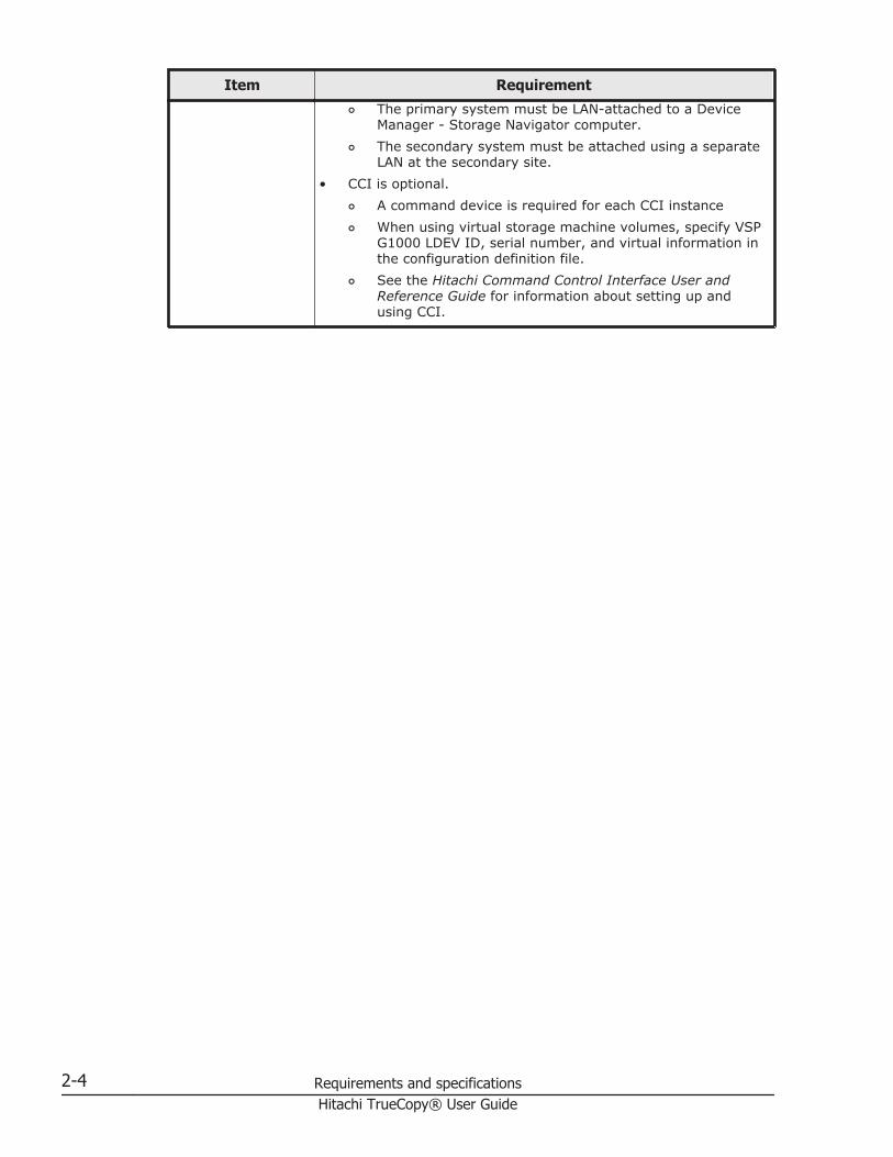
Item Requirement¢ The primary system must be LAN-attached to a Device
Manager - Storage Navigator computer.¢ The secondary system must be attached using a separate
LAN at the secondary site.• CCI is optional.
¢ A command device is required for each CCI instance¢ When using virtual storage machine volumes, specify VSP
G1000 LDEV ID, serial number, and virtual information inthe configuration definition file.
¢ See the Hitachi Command Control Interface User andReference Guide for information about setting up andusing CCI.
2-4 Requirements and specificationsHitachi TrueCopy® User Guide

3Planning for TrueCopy
This chapter provides information and instructions for planning primary andsecondary system, pair volumes, data paths, and other elements.
□ Storage system preparation
□ System performance considerations
□ Planning pairs and pair volumes
□ Consistency group planning
□ Host failover software
□ Data path requirements and configurations
Planning for TrueCopy 3-1Hitachi TrueCopy® User Guide

Storage system preparationThe following preparations are required for the storage systems in aTrueCopy pair relationship.
• Device Manager - Storage Navigator must be LAN-attached to the primaryand secondary system. See the Hitachi Command Suite User Guide forinformation.
• The primary and secondary system must be set up for TrueCopyoperations. See Cache, additional shared memory requirements on page3-2. Make sure to consider the amount of Cache Residency Manager datathat will be stored in cache when determining the amount of cache forTrueCopy operations.
• Make sure that the storage system is configured to report senseinformation by connecting storage system and host. It is required toconnect host to both primary and secondary system. If dedicated hostcannot be connected to secondary system, connect secondary system andhost at primary site.
• If power sequence control cables are used, set the power select switch forthe cluster to LOCAL to prevent the primary system from being poweredoff by the host. Make sure the S-VOL is not powered off during TrueCopyoperations.
• Install the data path between the primary and secondary system.Distribute data paths between different storage clusters and extenders orswitches to provide maximum flexibility and availability. The remote pathsbetween the primary and secondary system must be different than theremote paths between the host and secondary system. See Data pathrequirements and configurations on page 3-23 for more information.
Cache, additional shared memory requirementsCache must be operable for the pair's primary and secondary system,otherwise pairs cannot be created. The secondary system cache must beconfigured to adequately support TrueCopy remote copy workloads and anylocal workload activity.
Additional shared memory is prerequisite in both of the primary andsecondary system.
Note: Neither cache nor shared memory can be added to or removed fromthe storage system when pair status is COPY. When either of these tasks is tobe performed, first split any pairs in COPY status; then resynchronize thepairs when the cache or shared memory operation is completed.
Requirements for VSP G1000 with earlier model storage systemsYou can pair VSP G1000 volumes with VSP, USP V/VM, and HUS VM volumes.However, if the VSP G1000 volumes are in a consistency group consisting ofmultiple VSP G1000 systems, USP V/VM cannot be used. In this case, allpaired volumes must belong to VSP G1000, VSP, or HUS VM.
3-2 Planning for TrueCopyHitachi TrueCopy® User Guide

• When connecting VSP G1000 with VSP, USP V/VM, or HUS VM, contactHitachi Data Systems Support Center for information regarding thesupported microcode versions.
• When using the previous model storage system at the secondary site,make sure the primary and secondary system have unique serialnumbers.
Note: When using CCI (or Raidcom), the VSP G1000 serial numberrequires a prefix of "3".
System optionsYou can tailor VSP G1000 storage systems to enable options not specificallyset at the factory. System option modes related to TrueCopy are shown in thefollowing table.
VSP G1000 option modes are set to their default values at installation, andcan be changed only by your Hitachi Data Systems Support Center.
Optionmode Description
689 Allows you to slow the initial copy operation when the write-pending levelto the S-VOL is 60% or higher.• ON: When the S-VOL MP blade WritePending is 60% or higher, the
initial copy operation is inhibited.• OFF: Though the S-VOL MP blade WritePending is 60% or higher, the
initial copy operation is not inhibited.Do not set this mode if the primary or secondary system is connected toUSP V/VM with microcode earlier than 60-02-xx-xx/xx; otherwise TrueCopypairs may split.
784 Allows you to reduce RIO MIH time to 5-seconds. As a result, after aremote path error, less time elapses until the operation is retried on analternate path. (Both RIO MIH time and the Abort Sequence timeout valueare combined for this retry time.)• ON: Reduces the RIO MIH time to 5-seconds.
Combined with the Abort Sequence timeout value, the total amount oftime that elapses before the operation is retried on another path is amaximum of 10-seconds.
• OFF: The RIO MIH time that you specified at secondary systemregistration (default=15 seconds) is used with the specified AbortSequence timeout value.
System performance considerationsSynchronous copy operations affect I/O performance on the host and on theprimary and secondary systems. TrueCopy provides options for minimizingthe impact and for maximizing the efficiency and speed of copy operations forthe best level of backup data integrity. These options are discussed in:
Planning for TrueCopy 3-3Hitachi TrueCopy® User Guide

• Determining Round Trip Time on page 3-4• Determining Minimum Number of Remote Paths on page 3-6• Allowing I/O to the P-VOL after a split—Fence Level options on page
3-9
Performance is also optimized with the proper bandwidth. This is discussed inAnalyzing workload, planning data paths on page 3-6.
Determining Round Trip TimeYou specify a time limit in milliseconds for data to travel from the P-VOL tothe S-VOL when you set up the TrueCopy association between primary andsecondary system. Round Trip Time is used by the systems to control theinitial copy pace when update copying is in progress.
This section provides instructions for determining your system's Round TripTime.
Note the following Round Trip Time considerations:
• If the difference between Round Trip Time and remote IO response timeis significant, the system slows or even interrupts the initial copyoperation so that the update copy can continue.Example of significant difference between the two: 1ms RT Time : 500msremote IO response time.
• If the difference between the two is insignificant, initial copying is allowedto run at the specified pace.Example of insignificant difference between the two: 1ms : 5 ms
To determine Round Trip Time value
The value of Round Trip time= round trip time between primary system and secondarysystem x 2(*) + initial copy response time (ms)
(*) A data transfer between primary and secondary system involves two responsesequences in one command issuance. Therefore, you need to double the round trip time.But if the host mode option 51 (Round Trip Set Up Option) is enabled, responsesequence will be once for each command so you do not need to double the round triptime.
• For the "round trip time" in the formula, please ask your Hitachi DataSystems Support Center, or use a ping command. If you do not usechannel extenders between the primary and secondary system, specify"1".)
• The "initial copy response time" in the formula is the response timerequired for multiple initial copy operations. With the following formula,determine the initial copy response time using the initial copy pace, thenumber of maximum initial copy, and the bandwidth of the channelextender communication lines between primary and secondary system.
Initial copy response time (ms) = (1[MB] / "Data path speed between primarysystem and secondary system [MB/ms]1") x ("initial copy pace(2 / 4) x (number of
3-4 Planning for TrueCopyHitachi TrueCopy® User Guide

maximum initial copy3 " / "Number of data paths between primary system andsecondary system"4)
1. When you connect primary system with secondary system without extenders,set "Data path speed between primary system and secondary system" to eitherof below depending on the fiber cable link speed.2 Gbps : 0.17 MB/ms4 Gbps : 0.34 MB/ms8 Gbps : 0.68 MB/ms10 Gbps : 0.85 MB/ms16 Gbps : 1.36 MB/ms
2. For "initial copy pace" in the preceding formula, see the following table.3. For "number of maximum initial copy", use the value set up per storage system.
The default is 64.4. Even if the "number of maximum initial copy" / "Number of data paths between
primary system and secondary system" is larger than 16, specify "number ofmaximum initial copy VOLs" / "Number of data paths between primary systemand secondary system" as 16.
The following table shows the initial copy pace used for the response timecalculation.
Interface
When executing initial copyonly
When executing Initial, Updatecopy at the same time
When initialcopy pace
specified atthe time of
pair creation is1 to 4
When initialcopy pace
specified atthe time of
pair creation is5 to 15
When initialcopy pace
specified atthe time of
pair creation is1 to 2
When initialcopy pace
specified atthe time of
pair creation is3 to 15
Device Manager- StorageNavigator
User-specifiedvalue
4 User-specifiedvalue
2
CCI User-specifiedvalue
4 User-specifiedvalue
2
The following table shows example settings.
Round triptime
betweenprimary
system andsecondary
system [ms]
Data pathspeed
betweenprimarysystem
andsecondary
system(MB/ms)
Number ofdata pathsbetweenprimary
system andsecondary
system
Initial copypace
Number ofmaximuminitial copy
VOLs
Roundtriptime
specified [ms]
0 0.1 4 4 64 160
Planning for TrueCopy 3-5Hitachi TrueCopy® User Guide

Round triptime
betweenprimary
system andsecondary
system [ms]
Data pathspeed
betweenprimarysystem
andsecondary
system(MB/ms)
Number ofdata pathsbetweenprimary
system andsecondary
system
Initial copypace
Number ofmaximuminitial copy
VOLs
Roundtriptime
specified [ms]
30 0.1 4 4 64 220
100 0.1 4 4 64 360
Determining Minimum Number of Remote PathsYou specify the minimum number of remote paths to the secondary systemwhen you set up the TC association between primary and secondary systems.Using the Minimum Number of Paths option, you set a minimum valuefrom one to eight paths, with one being the default.
If the number of paths in Normal status drops below the specified minimum,the primary storage system splits the pair to avoid impact to hostperformance.
• To maintain high performance in the primary storage system, Hitachirecommends setting the minimum number at two.
• For a pair with important data, set the minimum at one. This allows thesystem to continue update operations to the secondary system.
• You can protect data integrity between P-VOL and S-VOL in the event thatthe system splits the pair because the number of paths is lower then theminimum. With the Fence Level setting (specified during the initial copy),you decide whether, when the pair is split due to an error, the hostcontinues to access the P-VOL or is denied access. See Allowing I/O to theP-VOL after a split—Fence Level options on page 3-9 for moreinformation.
Analyzing workload, planning data pathsYou optimize copy operations and performance by carefully planningbandwidth, number of data paths and host interface paths, and number ofports. This is discussed in:
Check with your Hitachi Data Systems Support Center for more information.
• Analyze write-workload. Bottlenecks severely impact performance, butthe workload data you collect (MB/s and IOPS) help determine thefollowing key elements that, when sized properly, form a data path thatoperates free of bottlenecks under all workload levels:
¢ Amount of bandwidth.¢ Number of data paths.
3-6 Planning for TrueCopyHitachi TrueCopy® User Guide

¢ Number of host-interface paths.¢ Number of ports dedicated for TrueCopy on the primary and
secondary system.• If you are setting up TrueCopy for disaster recovery, make sure that
secondary systems are attached to a host server. This enables both thereporting of sense information and the transfer of host failoverinformation. If the secondary site is unattended by a host, you mustattach the storage systems to a host server at the primary site so thatthe system administrator can monitor conditions.
Planning pairs and pair volumesThis section discusses requirements, options, and settings you need forsetting up pairs and pair volumes. You begin by:
• Identifying data and volumes at the primary site that you want to protectwith a backup
• Setting up volumes at the secondary site that will hold copied data.
The following helps ensure that the pairs you create fit your requirements.
• Pair volume requirements and recommendations on page 3-7• Allowing I/O to the S-VOL on page 3-9• Allowing I/O to the P-VOL after a split—Fence Level options on page
3-9• Differential data on page 3-10• Maximum number of pairs supported on page 3-10• Options and settings for number of pairs copied, and their priority, during
the initial copy and resync operations. See Priority for initial copyoperations and scheduling order on page 3-12
Pair volume requirements and recommendationsThe following is provided to help you prepare TrueCopy volumes:
• A volume can be assigned to only one pair.• Logical units on the primary and secondary storage systems must be
defined and formatted prior to pairing.• The P-VOL and S-VOL must be equal in size.• TrueCopy requires a one-to-one relationship between the P-VOL and S-
VOL. The P-VOL cannot be copied to more than one S-VOL, and an S-VOLcannot have more than one P-VOL.
• Logical Unit (LU) Types
¢ TrueCopy supports the basic LU types that can be configured on theVSP G1000 (for example, OPEN 3, OPEN E, OPEN 8, OPEN 9, OPEN L,OPEN V).
Planning for TrueCopy 3-7Hitachi TrueCopy® User Guide

¢ Pair volumes must consist of LUs of the same type and capacity (forexample, OPEN 3 to OPEN 3). The P-VOL and S-VOL LU types displayin Device Manager - Storage Navigator.
¢ Multi-platform volumes (for example, 3390 3A/B/C) cannot beassigned to pairs. Contact your Hitachi Data Systems Support Centerfor the latest information about supported devices for your platform.
• TrueCopy operates on volumes rather than on files; multi-volume filesrequire special attention. For complete duplication and recovery of amulti-volume file (for example, a large database file that spans severalvolumes), make sure that all volumes of the file are copied to TrueCopyS-VOL.
• TrueCopy pair volumes can be shared with non-TrueCopy Hitachi softwareproducts. See Chapter 4, Sharing TrueCopy volumes on page 4-1 formore information.
• TrueCopy supports Virtual LVI/LUN. This allows you to configure LUs thatare smaller than standard LUs. When custom-size LUs are assigned to aTrueCopy pair, the S-VOL must have the same capacity as the P-VOL.Device Manager - Storage Navigator displays the size of P-VOLs and S-VOL.
• Before creating multiple pairs during the Create Pairs operation, makesure to set up S-VOL LDEVs to allow the system to correctly match themto P-VOLs.You must do this because, even though you select multiple volumes as P-VOLs, you specify just one S-VOL. The system automatically assignssubsequent secondary system LDEVs as S-VOLs based on the option youspecify for Selection Type. These are the options:
¢ Interval: The interval you specify will be skipped between LDEVnumbers in the secondary system.For example, suppose you specify LU 01 as the initial (base) S-VOL,and specify 3 for Interval. This results in secondary system LDEV 04being assigned to the next P-VOL, 07 assigned to the subsequent P-VOL, and so on. To use Interval, you set up secondary system LDEVnumbers according to the interval between them.
¢ Relative Primary Volume. The difference is calculated between theLDEV numbers of two successive P-VOLs. S-VOLs are assignedaccording to the closest LUN number.For example, if the LUN numbers of three P-VOLs are 1, 5, and 6; andyou set LUN numbers for the initial S-VOL (Base Secondary Volume)at 2, the LUN numbers of the three S-VOLs will be set at 2, 6, and 7,respectively.
• Because the contents of the P-VOL and S-VOL are identical, the S-VOLcan be considered a duplicate of the P-VOL. Because the host operatingsystem does not allow duplicate volumes, the host system administratormust take precautions to prevent system problems related to duplicatevolumes. You must define the S-VOLs so they do not auto mount or comeonline to the same host at the same time as the P-VOLs.TrueCopy does not allow the S-VOL to be online (except when the pair issplit). If the S-VOL is online, the TrueCopy paircreate operation will fail.
3-8 Planning for TrueCopyHitachi TrueCopy® User Guide

Caution: When S-VOLs and P-VOLs are connected to the same hosts, it isstrongly recommended that you define the S-VOLs to remain offline. Thisis because under this condition, the S-VOL is usually offline when a pair isreleased. If the host is then restarted, the system administrator may beoffered both volumes and asked which volume should be left offline. Thiscan be confusing and is prone to error.
Allowing I/O to the S-VOLThe secondary system rejects write I/O to the S-VOL, unless the SecondaryVolume Written option is enabled. Then, read and write I/O is allowed to theS-VOL while the pair is split. In this instance, S-VOL and P-VOL track mapskeep track of differential data and are used to re-synchronize the pair.Enabling S-VOL-write is done during the pairsplit operation.
• You can write to S-VOL when the split operation is performed from theprimary system.
• When you resync a pair with the S-VOL write option enabled, thesecondary system sends S-VOL differential data to the primary system.This data is merged with P-VOL differential data, and out-of sync tracksare determined and updated on both systems, thus ensuring properresynchronization.
Allowing I/O to the P-VOL after a split—Fence Level optionsYou can specify whether the host is denied access or continues to access theP-VOL when the pair is split due to an error. This is done with the PrimaryVolume Fence Level setting. You specify one of the following Fence Leveloptions during the initial copy and resync operations. You can also change theFence Level option outside these operations.
• Data – the P-VOL is fenced if an update copy operation fails. Thisprevents the host from writing to the P-VOL during a failure. This settingshould be considered for the most critical volumes for disaster recovery.This setting reduces the amount of time required to analyze theconsistency of S-VOL data with the P-VOL during disaster recoveryefforts.
• Status – the P-VOL is fenced only if the primary system is not able tochange S-VOL status to suspended when an update copy operation fails.If the primary system successfully changes S-VOL pair status tosuspended, subsequent write I/O operations to the P-VOL will beaccepted, and the system will keep track of updates to the P-VOL. Thisallows the pair to be resynchronized quickly. This setting also reduces theamount of time required to analyze S-VOL consistency during disasterrecovery.
• Never – the P-VOL is never fenced. This setting should be used when I/Operformance out-weighs data recovery. "Never" ensures that the P-VOLremains available to applications for updates, even if all TrueCopy copyoperations have failed. The S-VOL may no longer be in sync with the P-VOL, but the primary system keeps track of updates to the P-VOL while
Planning for TrueCopy 3-9Hitachi TrueCopy® User Guide
the pair is suspended. Host failover capability is essential if this fencelevel setting is used. For disaster recovery, the consistency of the S-VOLis determined by using the sense information transferred via host failoveror by comparing the S-VOL contents with other files confirmed to beconsistent.
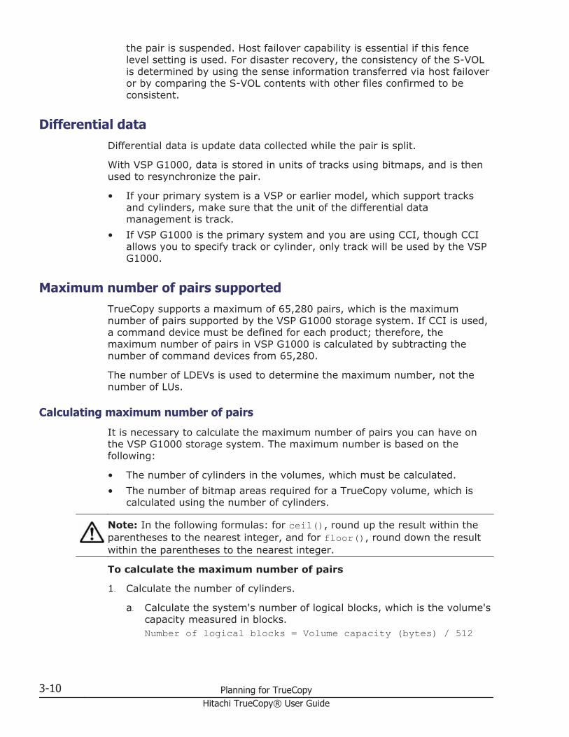
Differential dataDifferential data is update data collected while the pair is split.
With VSP G1000, data is stored in units of tracks using bitmaps, and is thenused to resynchronize the pair.
• If your primary system is a VSP or earlier model, which support tracksand cylinders, make sure that the unit of the differential datamanagement is track.
• If VSP G1000 is the primary system and you are using CCI, though CCIallows you to specify track or cylinder, only track will be used by the VSPG1000.
Maximum number of pairs supportedTrueCopy supports a maximum of 65,280 pairs, which is the maximumnumber of pairs supported by the VSP G1000 storage system. If CCI is used,a command device must be defined for each product; therefore, themaximum number of pairs in VSP G1000 is calculated by subtracting thenumber of command devices from 65,280.
The number of LDEVs is used to determine the maximum number, not thenumber of LUs.
Calculating maximum number of pairs
It is necessary to calculate the maximum number of pairs you can have onthe VSP G1000 storage system. The maximum number is based on thefollowing:
• The number of cylinders in the volumes, which must be calculated.• The number of bitmap areas required for a TrueCopy volume, which is
calculated using the number of cylinders.
Note: In the following formulas: for ceil(), round up the result within theparentheses to the nearest integer, and for floor(), round down the resultwithin the parentheses to the nearest integer.
To calculate the maximum number of pairs
1. Calculate the number of cylinders.
a. Calculate the system's number of logical blocks, which is the volume'scapacity measured in blocks.Number of logical blocks = Volume capacity (bytes) / 512
3-10 Planning for TrueCopyHitachi TrueCopy® User Guide

b. Calculate the number of cylinders:For OPEN-3, OPEN-8, OPEN-9, OPEN-E, OPEN-L, OPEN-K:Number of cylinders = ceil ( (ceil (Number of logicalblocks / 96) ) / 15)For OPEN-V.Number of cylinders = ceil ( (ceil (Number of logicalblocks / 512) ) / 15)
2. Calculate the number of bitmap areas per volume.In the following calculation, differential data is measured in bits. 122,752bits is the amount of differential data per bitmap area.For OPEN-3, OPEN-8, OPEN-9, OPEN-E, OPEN-L, OPEN-K, and OPEN-V:Number of bitmap areas = ceil ( (Number of cylinders x 15) /122,752)
Note: Doing this calculation for multiple volumes can result ininaccuracies. Perform the calculation for each volume separately, thentotal the bitmap areas. The following examples show correct and incorrectcalculations. Two volumes are used: one of 10,017 cylinders and anotherof 32,760 cylindersCorrect calculationceil ((10,017 x 15) / 122,752) = 2ceil ((32,760 x 15) / 122,752) = 5Total: 7Incorrect calculation10,017 + 32,760 = 42,777 cylindersceil ((42,777 x 15) / 122,752) = 6Total: 6
3. Calculate the maximum number of pairs, which is restricted by thefollowing:
¢ The number of bitmap areas required for TrueCopy (calculatedabove).
¢ The total number of bitmap areas in the storage system, which is65,536.Bitmap areas are also used by TrueCopy for Mainframe, UniversalReplicator, and Universal Replicator for Mainframe.Therefore, the number of bitmap areas used by these other programproducts (if any) must be subtracted from 65,536, with the differenceused to calculate the maximum number of pairs for TrueCopy.If TrueCopy and Universal Replicator share the same volume, youmust use the total number of bitmap areas for both pairs regardlessof whether the shared volume is primary or secondary.
¢ The maximum number of pairs supported per storage system, whichis 65,280 (65,279 if CCI is used).
Use the following formula:Maximum number of pairs = floor (Total number of bitmap areasin the storage system / Required number of bitmap areas)
Planning for TrueCopy 3-11Hitachi TrueCopy® User Guide

If the calculated maximum number of pairs exceeds the total number ofLDEVs of the storage system, and the total number of LDEVs of thestorage system is less than 65,280, then the total number of LDEVs of thestorage system becomes the maximum number of pairs.
Priority for initial copy operations and scheduling orderThough you can specify a maximum number of initial copies to runconcurrently, you are allowed to perform more initial copies than this whencreating pairs. If you do this, you will set the scheduling order for theadditional operations in the Initial Copy Priority field when creating the pair.
This topic provides two examples in which priority and the pre-set schedulingorder are discussed.
Example 1: more initial copies than previously specified
In this example, four initial copies are being created in the same operation,but Maximum Initial Copy Activities is set at 2. In this scenario, the InitialCopy Priority field in the Create TC Pairs window would be set as shown in thefollowing table.
P-VOL Value set for Initial Copy Priority
LUN 00 2
LUN 01 3
LUN 02 1
LUN 03 4
The order for the initial copy and the Initial Copy Priority for the P-VOLs areshown in the following table.
Order for initial copy P-VOL Value set for Initial CopyPriority
1 LUN 02 1
2 LUN 00 2
3 LUN 01 3
4 LUN 03 4
In this case, because the value of Maximum Initial Copy Activities is 2, initialcopy operations for LUN 02 and LUN 00 are started. If either one of the initialcopy operations for LUN 02 and LUN 00 is completed, the initial copy for LUN01 is started.
Example 2: initial copy started, new pairs added
The following table shows the Initial Copy Priority value when the initial copyis already begun and then two new pairs are added. The P-VOLs are for thenew pairs
3-12 Planning for TrueCopyHitachi TrueCopy® User Guide

P-VOL Value set for Initial Copy Priority
LUN 10 2
LUN 11 1
If initial copy is already started, and if a new initial copy is added, theadditional initial copy is started after the previously performed initial copy iscompleted. The priority of all the initial copy operations being performed isshown in the following table.
Starting order forinitial copy P-VOL
Value set forInitial Copy
PriorityRemarks
1 LUN 02 1 Previously scheduled.
2 LUN 00 2 Previously scheduled.
3 LUN 01 3 Previously scheduled.
4 LUN 03 4 Previously scheduled.
5 LUN 11 1 Scheduled later.
6 LUN 10 2 Scheduled later.
Initial Copy Priority is determined using the Edit Remote Replica Optionswindow within the range of the number of initial copy operations performedat the same time. Therefore, until the first initial copy operations complyingwith the order set by Initial Copy Priority are completed, the additional initialcopy operations are not started.
Consistency group planningConsistency groups allow you to perform one operation on all pairs in thegroup. Consistency groups also ensure that all pairs are managed in aconsistent status.
You determine which pairs to include in a particular consistency group. This isbased on business criteria for keeping status consistent across a group ofpairs, and for performing specific operations at the same time on the group.
• A consistency group can consist of the pairs in one primary and onesecondary VSP G1000, or pairs in multiple primary and secondary VSPG1000s.
• Both TC and TCz pairs can belong to the same consistency group.
Consistency group for pairs in one primary and one secondary VSPG1000
TC and TCz pairs between one primary and secondary system can be placedin the same consistency group, as shown in the following figure.
Planning for TrueCopy 3-13Hitachi TrueCopy® User Guide

Figure notes:
• TC pairs are assigned to a consistency group using CCI.TCz pairs are assigned to a consistency group using Business ContinuityManager (BCM).
• Open and mainframe volumes (P-VOLs/P-VOLs) receive I/O requests fromtheir applications at the primary (main) site, and data in the volumes isupdated.
• TC or TCz runs copy operations in the consistency group.
Consistency group for pairs in multiple primary and secondarysystems
TC and TCz pairs in multiple primary and secondary systems can be placed inthe same consistency group. A maximum of four storage system pairings canbe placed in the same consistency group.
3-14 Planning for TrueCopyHitachi TrueCopy® User Guide

Figure notes:
• CCI manages the consistency group on all primary and secondary system.Business Continuity Manager cannot be used with multiple systems.
• Open and mainframe primary volumes (P-VOLs/P-VOLs) receive I/Orequests from their applications at the primary (main) site, and data inthe volumes is updated.
• TrueCopy or TrueCopy for Mainframe runs the copy operation in theconsistency group.
• When the open or mainframe host system guarantees the update order,then data consistency in P-VOLs and S-VOLs is insured. When the hostsystem does not guarantee update order, data consistency is not insured.
Consistency group requirements Requirements are provided for the following consistency group (CTG)configurations.
• Consistency group for pairs in one primary and one secondary VSP G1000on page 3-13
• Consistency group for pairs in multiple primary and secondary systems onpage 3-14
Planning for TrueCopy 3-15Hitachi TrueCopy® User Guide

Requirements for a CTG for one primary and one secondary system
• A consistency group is configured on the primary and secondary system.• A maximum of 8,192 pairs can be assigned to a consistency group. (For
consistency group 127, the maximum is 4,096 pairs.)• A maximum of 256 consistency groups can be assigned to one primary
and one secondary system.• Assign a consistency group number in a range from 00-FF. The number
must be unused.• When you have multiple pairs in the same consistency group, they must
exist between the same primary and secondary system.• A pair can be assigned to one consistency group only.• TrueCopy pairs can be in the same consistency group as TrueCopy for
Mainframe pairs. Use the same consistency group number for both types.• When assigning pair volumes that belong to a virtual storage machine to
a consistency group consisting of one primary and one secondary system,all the P-VOLs in the consistency group must belong to the same virtualstorage machine.
• If you use BCM to resynchronize a TCz pair in an open/mainframeconsistency group with one primary and secondary system, all pairs in theconsistency group are resynchronized. Even if a TC S-VOL is beingaccessed by a host, the pair is nevertheless resynchronized with theothers. Make sure to check the status of all pairs in the consistency groupbefore resynchronizing.
• If you use BCM to delete a TCz pair in an open/mainframe consistencygroup with one primary and secondary system, only the TCz pairs aredeleted. Use CCI to delete the TC pairs.
Requirements for a CTG for multiple primary and secondary systems
• All requirements for a consistency group between one primary and onesecondary system apply to a consistency group between multiple primaryand secondary systems.
• The primary and secondary systems can be VSP G1000 or VSP. No othermodels can be used.
• A consistency group can consist of a maximum of four primary and foursecondary (paired) systems.
• The microcode for both primary and secondary systems must supportconsistency groups between multiple primary and secondary systems;otherwise, pair creation results in failure.
• You must install the version of CCI that supports a consistency groupconsisting of multiple primary systems and secondary systems.
• Pair operations can be performed from CCI only. Business ContinuityManager and Device Manager - Storage Navigator do not support pairoperations for pairs in a CTG with multiple VSP G1000s.
• Cascade configurations with Universal Replicator pairs is not supported.
3-16 Planning for TrueCopyHitachi TrueCopy® User Guide

• You can assign pair volumes that belong to multiple virtual storagemachines to a consistency group consisting of multiple primary andsecondary systems.
Assigning pairs to a consistency groupPairs are assigned to a consistency group (CTG) during the Paircreateoperation. The procedure to assign pairs depends on the number of VSPG1000s in the CTG, as follows:
• Assigning pairs belonging to one primary and secondary system on page3-17
• Assigning pairs belonging to multiple primary and secondary systems onpage 3-17
Assigning pairs belonging to one primary and secondary system
The method for assigning pairs to a consistency group differs according to theGUI used to create the pairs:
• When using Device Manager - Storage Navigator, only consistency group127 is supported. See Consistency group 127 on page 3-21 for moreinformation.
• When using CCI, see the Hitachi Command Control Interface User andReference Guide
• When using Business Continuity Manager, see the Business ContinuityManager User Guide
Assigning pairs belonging to multiple primary and secondary systems
Assigning pairs in multiple primary and secondary systems to a consistencygroup depends on whether you are:
• Using a new CTG on page 3-17• Using an existing CTG on page 3-18
CCI is used when creating and assigning pairs to a consistency group onmultiple VSP G1000s. Business Continuity Manager is not supported for thisconfiguration.
Using a new CTG
You can assign new pairs or existing pairs to a new consistency group.
To assign new pairs to a new consistency group
1. Create CCI configuration definition file C for a multiple primary andsecondary system configuration.
2. Perform the paircreate operation according to configuration definition fileC created in Step 1.
Planning for TrueCopy 3-17Hitachi TrueCopy® User Guide

To assign existing pairs to a new consistency group
1. Create CCI configuration definition file A with which to use CCI for pairoperations.
2. Perform the pairsplit operation according to configuration definition file Acreated in Step 1.
3. Perform the pairresync operation without designating a consistencygroup. Do this using configuration definition file A.
4. Perform the pairsplit operation again using configuration definition file A.5. Create CCI configuration definition file C for the multiple primary and
secondary system configuration.6. Perform the pairresync operation and register them to configuration
definition file C.
Using an existing CTG
You can assign new pairs or existing pairs to an existing consistency group.
To assign new pairs to an existing consistency group
1. Add pair information to the existing configuration definition file B, whichconsists of pairs in multiple VSP G1000s.
2. Copy and create CCI configuration definition file C.3. Perform the paircreate operation and register them to configuration
definition file C.
To assign existing pairs to an existing consistency group
1. Create CCI configuration definition file A to use with CCI for pairoperations.
2. Perform the pairsplit operation on pairs that you want to register in theexisting CTG with multiple systems. Do this using configuration definitionfile A.
3. Perform the pairresync operation without designating a consistencygroup. Do this using configuration definition file A.
4. Perform the pairsplit operation again using configuration definition file A.5. Perform the pairsplit operation to the existing configuration definition file
B, which consists of the pairs in the multiple primary and secondarysystem configuration.
6. Add pair information to existing configuration definition file B.7. Delete then re-create the pairs, registering them in configuration
definition file C.
Split behaviors for pairs in a CTGWhen the pairs in a consistency group receive updates while in the process ofbeing split or suspended, or when they are about to be split or suspended, S-VOL data consistency is managed as follows:
3-18 Planning for TrueCopyHitachi TrueCopy® User Guide

• If I/O processing is in progress on pairs in the same consistency group,and the split or suspend operation begins, the I/O processing completesfirst, then the split/suspend operation is run.The following figure shows that I/O processing completes first; then thepair split operation for the pair on Volume B completes.
The following figure shows data in track 2 being copied to the S-VOL, and thedata in track 3 becomes differential data. In this case, track 2 is used for I/Oprocessing to the volume in the consistency group when the split command isissued to the pair.
• If a split operation is in progress when I/O processing on the pairs begins,the split operation on the pairs is given priority. After the pair is split,then the I/O processing begins.
• Data consistency cannot be ensured when all of the following conditionsexist:- A port is blocked.
Planning for TrueCopy 3-19Hitachi TrueCopy® User Guide

- A split command is in progress.- I/O processing begins.In such a case, resynchronize the consistency group and then run thesplit command again.
Host access after split
You can specify settings for read/write access to the P-VOL/P-VOL and S-VOL/S-VOL in consistency groups after pairs are split. These settings arespecified using CCI or Business Continuity Manager.
• The CCI settings for TC are optional.• The Business Continuity Manager settings for TCz are required.
The following tables show the effects of the settings on read and write access.
Interface SettingTC P-VOL TCz P-VOL
Read Write Read Write
CCI Write access prohibited Y N Y N
No option selected Y Y Y Y
BusinessContinuityManager
Write access prohibited Y N Y N
Write access permitted Y Y Y Y
Interface SettingTC S-VOL TCz S-VOL
Read Write Read Write
CCI Read access permitted Y N N N
Read/Write access permitted Y Y Y Y
No option selected Y N N N
BusinessContinuityManager
Write access prohibited Y N N N
Write access permitted Y Y Y Y
Pair status before and after a split operation
Pairs in the same consistency group must be in PAIR/Duplex status when youbegin the split operation in order to maintain consistency. Otherwise, whenthe operation completes, pair status will be inconsistent.
This is shown in the following table, in which font angle indicates thefollowing:
• Italics font: Pair status before the split operation on the consistency group• Regular font: Status after the split operation
3-20 Planning for TrueCopyHitachi TrueCopy® User Guide

Pair statusesTCz pairs
All = Duplex Some = Duplex, some= Suspend All = Suspend
TCpairs
All = PAIR TC: PSUSTCz: Suspend
TC: PSUSTCz: Suspend
TC: PSUSTCz: Suspend
Some = PAIR,some = PSUS
TC: PSUSTCz: Suspend
TC: PSUSTCz: Suspend
TC: PSUSTCz: Suspend
All = PSUS TC: PSUSTCz:- CCI: Duplex- BCM: Suspend
TC: PSUSTCz:- CCI: Duplex/Suspend- BCM: Suspend
TC: PSUSTCz: Suspend
Consistency group 127When you create pairs using Device Manager - Storage Navigator, they canbe assigned to only one consistency group, 127. (You can also use CCI toassign pairs to CTG 127.) With CTG 127, you can ensure the following:
• When a pair is split or suspended for any reason, you can ensure that allP-VOLs in the group become suspended.
• If data paths between the secondary and primary system fail, you canensure that all S-VOLs are placed in PSUE status.
For more information, see CTG 127 behavior and restrictions when a pair issuspended on page 3-21.
To assign pairs to CTG 127
1. Turn Function Switch 30 On.
¢ Turn on the switch in the primary and secondary system to get thedesired result in each system.
¢ Turn on the switch in the system where you want the behavior: eitherconsistent P-VOL suspensions for the primary system, or consistent S-VOL PSUE status for the secondary system.
2. Create the pairs and assign them to CTG 127.
¢ In CCI, assign the pairs to this group number when you create thepairs.
¢ In Device Manager - Storage Navigator, pairs are automaticallyassigned to CTG 127 when the pairs are created and function switch30 is On.
CTG 127 behavior and restrictions when a pair is suspended
Note the following behaviors and restrictions regarding the consistentsuspending of all P-VOLs when a pair suspends.
Planning for TrueCopy 3-21Hitachi TrueCopy® User Guide
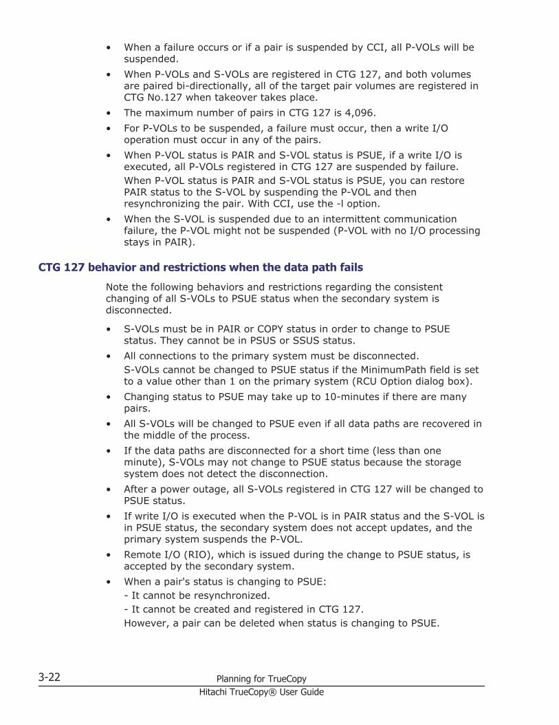
• When a failure occurs or if a pair is suspended by CCI, all P-VOLs will besuspended.
• When P-VOLs and S-VOLs are registered in CTG 127, and both volumesare paired bi-directionally, all of the target pair volumes are registered inCTG No.127 when takeover takes place.
• The maximum number of pairs in CTG 127 is 4,096.• For P-VOLs to be suspended, a failure must occur, then a write I/O
operation must occur in any of the pairs.• When P-VOL status is PAIR and S-VOL status is PSUE, if a write I/O is
executed, all P-VOLs registered in CTG 127 are suspended by failure.When P-VOL status is PAIR and S-VOL status is PSUE, you can restorePAIR status to the S-VOL by suspending the P-VOL and thenresynchronizing the pair. With CCI, use the -l option.
• When the S-VOL is suspended due to an intermittent communicationfailure, the P-VOL might not be suspended (P-VOL with no I/O processingstays in PAIR).
CTG 127 behavior and restrictions when the data path fails
Note the following behaviors and restrictions regarding the consistentchanging of all S-VOLs to PSUE status when the secondary system isdisconnected.
• S-VOLs must be in PAIR or COPY status in order to change to PSUEstatus. They cannot be in PSUS or SSUS status.
• All connections to the primary system must be disconnected.S-VOLs cannot be changed to PSUE status if the MinimumPath field is setto a value other than 1 on the primary system (RCU Option dialog box).
• Changing status to PSUE may take up to 10-minutes if there are manypairs.
• All S-VOLs will be changed to PSUE even if all data paths are recovered inthe middle of the process.
• If the data paths are disconnected for a short time (less than oneminute), S-VOLs may not change to PSUE status because the storagesystem does not detect the disconnection.
• After a power outage, all S-VOLs registered in CTG 127 will be changed toPSUE status.
• If write I/O is executed when the P-VOL is in PAIR status and the S-VOL isin PSUE status, the secondary system does not accept updates, and theprimary system suspends the P-VOL.
• Remote I/O (RIO), which is issued during the change to PSUE status, isaccepted by the secondary system.
• When a pair's status is changing to PSUE:- It cannot be resynchronized.- It cannot be created and registered in CTG 127.However, a pair can be deleted when status is changing to PSUE.
3-22 Planning for TrueCopyHitachi TrueCopy® User Guide
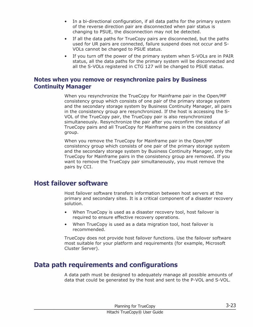
• In a bi-directional configuration, if all data paths for the primary systemof the reverse direction pair are disconnected when pair status ischanging to PSUE, the disconnection may not be detected.
• If all the data paths for TrueCopy pairs are disconnected, but the pathsused for UR pairs are connected, failure suspend does not occur and S-VOLs cannot be changed to PSUE status.
• If you turn off the power of the primary system when S-VOLs are in PAIRstatus, all the data paths for the primary system will be disconnected andall the S-VOLs registered in CTG 127 will be changed to PSUE status.
Notes when you remove or resynchronize pairs by BusinessContinuity Manager
When you resynchronize the TrueCopy for Mainframe pair in the Open/MFconsistency group which consists of one pair of the primary storage systemand the secondary storage system by Business Continuity Manager, all pairsin the consistency group are resynchronized. If the host is accessing the S-VOL of the TrueCopy pair, the TrueCopy pair is also resynchronizedsimultaneously. Resynchronize the pair after you reconfirm the status of allTrueCopy pairs and all TrueCopy for Mainframe pairs in the consistencygroup.
When you remove the TrueCopy for Mainframe pair in the Open/MFconsistency group which consists of one pair of the primary storage systemand the secondary storage system by Business Continuity Manager, only theTrueCopy for Mainframe pairs in the consistency group are removed. If youwant to remove the TrueCopy pair simultaneously, you must remove thepairs by CCI.
Host failover softwareHost failover software transfers information between host servers at theprimary and secondary sites. It is a critical component of a disaster recoverysolution.
• When TrueCopy is used as a disaster recovery tool, host failover isrequired to ensure effective recovery operations.
• When TrueCopy is used as a data migration tool, host failover isrecommended.
TrueCopy does not provide host failover functions. Use the failover softwaremost suitable for your platform and requirements (for example, MicrosoftCluster Server).
Data path requirements and configurationsA data path must be designed to adequately manage all possible amounts ofdata that could be generated by the host and sent to the P-VOL and S-VOL.
Planning for TrueCopy 3-23Hitachi TrueCopy® User Guide

This topic provides requirements and planning considerations for the followingkey elements of the data path:
• Bandwidth requirements on page 3-24• Fibre Channel requirements on page 3-24• Supported data path configurations on page 3-25• Ports on page 3-28
Bandwidth requirementsSufficient bandwidth must be present to handle data transfer of all workloadlevels. The amount of bandwidth required for your TrueCopy system is basedon the amount of I/O sent from the host to the primary system. Youdetermine required bandwidth by measuring write-workload. Workload data iscollected using performance monitoring software. Consult your Hitachi DataSystems Support Center for more information.
Fibre Channel requirementsThe primary and secondary system must be connected using multimode orsingle-mode optical fibre cables. As shown in the following table, the cablesand data path relay equipment required depend on the distance between theP-VOL and S-VOL storage systems.
Distance Fibre cable type Data path relayequipment
0.5 km to 1.5 km (4,920feet)
Multimode shortwave FibreChannel interface cables.
At least one switch isrequired, and a maximum oftwo switches can be used.
1.5 km to 10 km (6.2miles)
Single-mode longwave2 opticalfibre cables.
Not required.
10 km to 30 km (18.6miles)
Single-mode longwave2 FibreChannel interface cables.
Up to two switches can beused.
Greater than 30 km(18.6 miles)1
Communications lines arerequired.
Approved third-party channelextender products.3
1. TrueCopy operations typically do not exceed 30 km.2. Longwave cannot be used for FCoE.3. For more information about approved channel extenders, contact HDS (see Getting
help on page xiii).
With Fibre Channel connections, no special settings are required for VSPG1000.
Direct connections up to 10 km with single-mode longwave Fibre Channelinterface cables are supported. Link speed determines the maximum distanceyou can transfer data and still achieve good performance. The following tableshows maximum distances at which performance is maintained per linkspeed, over single-mode longwave Fibre Channel.
3-24 Planning for TrueCopyHitachi TrueCopy® User Guide

Link speed Distance maximum performance maintained
1 Gbps 10 km
2 Gbps 6 km
4 Gbps 3 km
8 Gbps 2 km
16 Gbps 1 km
Your Hitachi Data Systems Support Center can provide the latest informationabout the availability of serial-channel TrueCopy connections.
Supported data path configurationsThree Fibre Channel configurations are supported for TrueCopy:
• Direct connection on page 3-26• Switch connection on page 3-26• Extender connection on page 3-27
LUN Manager is used to set port topology.
For direct and switch connections, host I/O response time can be improvedon long distance direct connections (longwave, less than 10km/6.2 miles) byimproving the I/O response time between storage systems and by using hostmode options 49 and 50, or 51. The following table describes these optionsfor the open package. Hitachi Data Systems-approved channel extender isrequired. For more information on host mode options, see the Hitachi VirtualStorage Platform G1000 Provisioning Guide for Open Systems.
No Host modeoptions Description
49 BB Credit Set UPOption 1
Fixes higher values of buffer-to-buffer credits (BBCs) toincrease data transfer size over long distances.1 Thishost mode option must be used in conjunction with hostmode option 50.2
50 BB Credit Set UPOption 2
Fixes higher values of buffer-to-buffer credits (BBCs) toincrease data transfer size over long distances.1 Thishost mode option must be used in conjunction with hostmode option 49.2
513 Round Trip SetUP Option
Improves host I/O response time for long distance switchconnections.2
Notes:1. Up to 10 km for direct connection and 100 km for switch connection.2. The microcode supporting these functions must be installed on both the primary and
secondary systems.3. Host mode option 51 is not supported for 8FC16 or 16FE10 packages.
Planning for TrueCopy 3-25Hitachi TrueCopy® User Guide

Direct connection
The following figure shows a direct connection, in which two devices areconnected directly together.
Set port topology to: Fab off, FC-AL.
As shown in the following table, Fab settings, topology settings, and availablelink speed depend on the settings of the packages and protocols used for thestorage system connections, as well as whether host mode option 51 is used.
Packagename Protocol Host mode
option 51 FabInitiator port andRCU target port
topologyAvailable link speed
16FC8 8GbpsFC OFF OFF FC-AL • 2 Gbps• 4 Gbps• 8 Gbps
ON OFF Point-to-Point • 2 Gbps• 4 Gbps• 8 Gbps
8FC16 16GbpsFC OFF OFF FC-AL • 4 Gbps• 8 Gbps
Switch connection
The following figure shows a switch connection, in which up to three opticalfibre cables are connected using switches. Two switches can be used.
Set port topology to the following:
• NL port: Fab on, FC-AL• N port: Fab on, Point-to-Point• Some switch vendors require F port (for example, McData ED5000).
3-26 Planning for TrueCopyHitachi TrueCopy® User Guide

As shown in the following table, Fab settings, topology settings, and availablelink speed depend on the settings of the packages and protocols used for thestorage system connections, as well as whether host mode option 51 is used.
Packagename Protocol
Hostmode
option 51Fab
Initiator port andRCU target port
topologyAvailable link speed
16FC8 8GbpsFC OFF ON Point-to-Point • 2 Gbps• 4 Gbps• 8 Gbps
ON ON Point-to-Point • 2 Gbps• 4 Gbps• 8 Gbps
8FC16 16GbpsFC OFF ON Point-to-Point • 4 Gbps• 8 Gbps• 16 Gbps
16FE10 10GbpsFCoE OFF ON Point-to-Point 10 Gbps
Extender connection
The following figure shows an extender connection, in which channelextenders and switches are used to connect the devices across largedistances.
Figure 3-1 Extender Connection
• Set port topology to the following:
¢ NL/FL port: Fab on, FC-AL¢ F port: Fab on, Point-to-Point
• Best practice is to create at least two independent data paths (one percluster) between the primary and secondary system for hardwareredundancy for this critical element.
• When 4,000 pairs or more are used, we recommend that you restrict thenumber of pairs when creating pairs, so that 4,000 pairs or less use onephysical path, to distribute load on the physical path.
Planning for TrueCopy 3-27Hitachi TrueCopy® User Guide

• The same write-workload would be used in the reverse direction in adisaster recovery scenario. Therefore, when planning TrueCopy fordisaster recovery, the same number of secondary-to-primary data pathsmust be set up as the primary-to-secondary copy paths for normaloperations. Reverse direction paths must be set up independently of theprimary-to-secondary paths.
• When you set up secondary-to-primary data paths, specify the samecombination of CUs or CU Free, and the same path group ID, as specifiedfor the primary-to-secondary paths.
PortsData is transferred along the data path from the initiator to the RCU targetports on the primary and secondary system. The amount of data each ofthese ports can transmit is limited.
Therefore, you must know the amount of data that will be transferred (write-workload) during peak periods. You can then ensure not only that bandwidthmeets data transfer requirements, but that a sufficient number of eachsystem's ports are specified as initiator and RCU target ports to handle allworkload levels.
Port requirements
Data is sent from the storage system port across the data path to thereceiving system's port.
Note: One secondary system port can be connected to a maximum of 16ports on a primary system. The number of remote paths that can be specifieddoes not depend on the number of ports configured for TrueCopy. You canspecify the number of remote paths for each remote connection.
Note: Make sure not to add or delete a remote connection, or add a remotepath at the same time that the SCSI path definition function for LUN Manageris in use.
Port attributes
Plan and define the following Fibre Channel port attributes for TrueCopy:
• Initiator ports, which send data. One initiator port can be connected toa maximum of 64 RCU target ports. Configure initiator ports on bothprimary and secondary system for TrueCopy disaster recovery operations.
• RCU target ports, which receive data. Configure RCU target ports onboth primary and secondary system for TrueCopy disaster recoveryoperations.
• Target port: Connects the storage system and a host. When the hostissues a write request, the request is sent to a volume on the VSP G1000system via a target port on the storage system. Target ports must beconfigured on the primary system for TrueCopy operations.
3-28 Planning for TrueCopyHitachi TrueCopy® User Guide
• External port: Required for Universal Volume Manager copy operations.This port is not used for TrueCopy copy operations. This port can bechanged to a target, initiator, or RCU target port.
Planning for TrueCopy 3-29Hitachi TrueCopy® User Guide

3-30 Planning for TrueCopyHitachi TrueCopy® User Guide

4Sharing TrueCopy volumes
This chapter helps you plan TrueCopy (TC) pair volumes when they areshared with non-TC volumes. All the software products that can be used withTC are discussed here.
□ Volume types that can be shared with TrueCopy
□ Cache Residency Manager
□ Data Retention Utility
□ Dynamic Provisioning
□ Global storage virtualization
□ LUN Manager
□ Performance Monitor
□ ShadowImage
□ Universal Replicator
□ Virtual LUN
□ Volume Migration
Sharing TrueCopy volumes 4-1Hitachi TrueCopy® User Guide

Volume types that can be shared with TrueCopyThe following table shows when volumes used by other software can also beused as TC P-VOLs and S-VOLs.
Volume type Used as TC P-VOL? Used as TC S-VOL?
Cache Residency Manager
Cache Residency Manager volume Yes Yes
Virtual LUN
Virtual LUN volume Yes Yes
Copy-on-Write Snapshot (SS) and Thin Image (TI)
P-VOL in all statuses except COPY(RS-R)/RCPY
Yes Yes
P-VOL in COPY(RS-R)/RCPY status No No
TI/SS P-VOL used as UR P-VOL or S-VOL No No
V-VOL No No
Pool-VOL No No
Cross-OS File Exchange
Volume usable by both mainframe andopen systems
No No
Data Retention Utility
Volume with Read/Write attribute Yes Yes
Volume with Read Only attribute Yes Yes
Volume with Protect attribute Yes Yes
Volume that is disabled for use as an S-VOL Yes No
Dynamic Provisioning
DP-VOL Yes Yes
Pool vol No No
Dynamic Tiering
DP-VOL Yes Yes
Pool vol No No
global storage virtualization
Volumes in a virtual storage machine Yes Yes
Global-active device(GAD)
P-VOL No No
S-VOL No No
Quorum disk No No
Volume with reserve attribute for S-VOL No No
4-2 Sharing TrueCopy volumesHitachi TrueCopy® User Guide

Volume type Used as TC P-VOL? Used as TC S-VOL?
LUN Manager
Volume to which a path is defined Yes Yes
Volume to which no path is defined No No
Volume to which LUN security is applied Yes Yes
ShadowImage (SI)
P-VOL in PSUS (Delete pair to RCU) status Yes Yes
P-VOL in COPY(RS-R)/RCPY status No No
SI P-VOL is also used as a UR P-VOL or S-VOL
No No
P-VOL (none of the above) Yes Yes
S-VOL in PSUS (Delete pair to RCU) status Yes No
S-VOL (none of the above) No No
Reserved volume No No
Universal Replicator (UR)
P-VOL in COPY status No No
P-VOL in PAIR status Yes2 No3
P-VOL in PSUS (Delete pair to RCU) status Yes2 No4
P-VOL in PSUE (pair suspended-error)status
Yes2 No4
S-VOL in COPY status No No
S-VOL in PAIR status No No
S-VOL in PSUS (Delete pair to RCU) status Yes No
S-VOL in SSWS status Yes No
S-VOL in PSUE (pair suspended-error)status
Yes No
Universal Volume Manager
Mapped external volume Yes Yes
Virtual Partition Manager(VPM)
Volume belonging to the Virtual PartitionManager CLPR
Yes Yes
Volume Migration1
Source volume (when volume migration isin progress)
Yes. (If the sourcevolume is a P-VOL,volume migrationwill stop.)
Yes. (If the sourcevolume is an S-VOL,volume migrationwill stop.) 5
Source volume (after volume migration isfinished)
Yes Yes
Sharing TrueCopy volumes 4-3Hitachi TrueCopy® User Guide

Volume type Used as TC P-VOL? Used as TC S-VOL?
Target volume No No
Reserved volume No No
1. For more information about using Volume Migration, contact Hitachi Data SystemsSupport Center.
2. The volume cannot be used if the corresponding UR pair belongs to a journal that isconfigured for 2DC configurations.
3. The volume can be used only when you resynchronize a TC pair or perform a CCIhorctakeover operation. In this case, even though the corresponding UR pairbelongs to a journal that is configured for 2DC configurations, the volume can beused.
4. The volume can be used only when you resynchronize a TC pair or perform a CCIhorctakeover operation, except when the corresponding UR pair belongs to a journalthat is configured for 2DC configurations.
5. If the TC S-VOL is a DP-VOL, the TC pair cannot be created. Create the TC pair aftercompleting volume migration or stopping the Volume Migration operation.
6. The volume which virtual LDEV ID is deleted cannot be used as pair volume of TC.
The following topics include additional information about shared volumes.
Cache Residency ManagerThe volumes which set the Cache Residency Manager can be assigned as theTrueCopy pair. You can perform Cache Residency Manager operations on TCP-VOLs and S-VOLs. For more information, see the Hitachi Virtual StoragePlatform G1000 Performance Guide.
Data Retention UtilityYou can create a TC pair using volumes that have been assigned the accessattribute by the Data Retention Utility (DRU). However, you cannot specify avolume with the "S-VOL Disable" attribute as a TC S-VOL.
The following table shows whether a DRU volume with the specified accessattribute can be used as a TC P-VOL or S-VOL.
DRU access attributeAvailability of TC P-VOL or S-VOL
P-VOL S-VOL
Read/Write Yes Yes
Read Only Yes Yes
Protect Yes Yes
S-VOL Disable Yes No
Read Only and S-VOL Disable Yes No
Protect and S-VOL Disable Yes No
4-4 Sharing TrueCopy volumesHitachi TrueCopy® User Guide

The following tables show TC volumes and status with Data Retention Utilityoperations that can be performed using Device Manager - Storage Navigator.
TCVolume
PAIRstatus
DRU operation
Changing access attribute Referringaccess
attributeRead/Write Read Only Protect S-VOL
Disable
P-VOL SMPL Yes Yes Yes Yes Yes
COPY Yes Yes Yes Yes Yes
PAIR Yes Yes Yes Yes Yes
PSUS Yes Yes Yes Yes Yes
PSUE Yes Yes Yes Yes Yes
S-VOL SMPL Yes Yes Yes Yes Yes
COPY No No No No Yes
PAIR No No No No Yes
PSUS Yes Yes Yes Yes Yes
PSUE Yes Yes Yes Yes Yes
The following tables show TC volumes and status with the Data RetentionUtility operations that can be performed using Device Manager - StorageNavigator and CCI.
TCVolume
PAIRstatus
DRU operation
Changing access attribute Referringaccess
attributeRead/Write Read Only Protect S-VOL
Disable
P-VOL SMPL Yes Yes Yes Yes Yes
COPY Yes Yes Yes Yes Yes
PAIR Yes Yes Yes Yes Yes
PSUS Yes Yes Yes Yes Yes
PSUE Yes Yes Yes Yes Yes
S-VOL SMPL Yes Yes Yes Yes Yes
COPY Yes Yes Yes No Yes
PAIR Yes Yes Yes No Yes
PSUS Yes Yes Yes Yes Yes
PSUE Yes Yes Yes Yes Yes
Sharing TrueCopy volumes 4-5Hitachi TrueCopy® User Guide

Dynamic ProvisioningYou can create a Universal Replicator pair by specifying a DP-VOL (DynamicProvisioning virtual volume). DP-VOLs can be assigned to both the TC P-VOLand S-VOL, or to one of them. However, the following restrictions apply:
• You can use DP-VOLs that are also used in a ShadowImage pair, or in aVolume Migration migration plan. Before creating the TC pair, delete theSI pair, or disable the Volume Migration setting. After the pair is created,then re-create the pair or migration plan.
• When a DP-VOL has pages allocated to an S-VOL, used pool capacity istemporarily larger than the actual capacity because pages must bereallocated in the DP-VOL. Therefore, before creating the pair, make sureof the following:
¢ DP-VOL pool capacity is sufficient.¢ Pool-VOLs that are added to a pool are not blocked. If Pool-VOLs are
blocked, restore the volume status and then create the pair.• Regarding page and license capacity:
¢ If a pair does not include a DP-VOL, volume capacity is countedtoward TC license capacity.If a pair includes a DP-VOL, only the allocated page capacity ofvolume capacity is counted toward TC license capacity.If a DP-VOL and a non-DP-VOL are included in a pair, the pagecapacity and/or license capacity counted in the P-VOL and the S-VOLmay be different. This applies even when both P-VOL and S-VOLinclude DP-VOLs, because the page capacity of the P-VOL or the S-VOL changes by a relocated pool or released page or other action.
For more information, see the Hitachi Virtual Storage Platform G1000Provisioning Guide for Open Systems.
Global storage virtualizationPairs can be created using volumes in a virtual storage machine. Please notethe following:
• Though Device Manager - Storage Navigator displays the virtual LDEV IDof a volume belonging to a virtual storage machine, make sure whenrunning pair operations in Device Manager - Storage Navigator that youspecify the physical VSP G1000 LDEV ID.
• A volume's virtual ID used with TrueCopy cannot be deleted.
LUN Manager • LUN Manager operations do not affect TC operations.• Volumes that are under secure ports and/or that are assigned to host
groups can also be assigned to TC pairs.
4-6 Sharing TrueCopy volumesHitachi TrueCopy® User Guide

• Volumes that are assigned to TC pairs can also be assigned to secureports and host groups for LUN Manager.
• TC S-VOLs cannot be accessed by any UNIX/PC server host except whenthe pair is split.
For more information, see the Hitachi Virtual Storage Platform G1000Provisioning Guide for Open Systems.
Performance MonitorPerformance Monitor software provides detailed information about I/O activityand hardware performance in VSP G1000 systems. Storage system usageand performance data is collected and displayed by Performance Monitor.This information helps you to:
• Identify the optimum timing for performing TC operations.• Determine the best locations for the TC S-VOL (for example, parity
groups with less-frequently accessed volumes to avoid bottlenecks ofbackend activity).
• Monitor system performance during TC operations and during testingactivities.
See the Hitachi Virtual Storage Platform G1000 Performance Guide for moreinformation.
ShadowImageShadowImage volumes can be assigned to TC pairs, and TC volumes can beassigned to SI pairs. The following table shows the configurations that arepossible.
TC volume SI P-VOL SI S-VOL
P-VOL Yes Yes
S-VOL Yes No
Please note the following when sharing TC volumes with SI volumes.
• L1 and L2 SI pairs can be shared with TC volumes. Both node and leaf S-VOLs are considered secondary volumes by TC.
• SI is recommended for in-system copy operations. However, if SI is notinstalled, TC can be used to copy within the same VSP G1000. Thisconfiguration requires at least one fibre cable loop.
• The SI Quick Restore can be performed when the TC pair is suspended.For information about the Quick Restore operation, see the HitachiShadowImage® User Guide.
Sharing TrueCopy volumes 4-7Hitachi TrueCopy® User Guide

Configurations with ShadowImage P-VOLsTC can share an SI P-VOL in three configurations:
• In the following figure, the TC P-VOL also functions as an SI P-VOL. Thisconfiguration allows you to use SI for on-site data backup in case of TCfailure. Or, the TC S-VOL can be used to provide remote backup of the SIP-VOL in case of an SI failure.
Figure 4-1 Shared TC P-VOL with SI P-VOL
• In the following figure, the TC S-VOL also functions as an SI P-VOL. Inthis configuration, SI provides another (or several more) backup copies ofa TC P-VOL.When an SI P-VOL is shared with the TC S-VOL, the write operation to theTC P-VOL takes a longer time than normal. This is especially true whenthe SI pair is in the PSUS(SP)/PSUS status and is caused by the SIcopying process.
Figure 4-2 Shared TC S-VOL with SI P-VOL
• In the following figure, the configurations shown in the previous twofigures are combined. Both the TC P-VOL and S-VOL function as SI P-VOLs, providing multiple copies at the primary and secondary sites.
Figure 4-3 Shared TC P-VOL, S-VOL with multiple SI P-VOLs
Configurations with ShadowImage S-VOLsIn the following figure, an SI S-VOL also functions as a TC P-VOL. Thisconfiguration requires that the SI pair is split before the TC pair is created.
4-8 Sharing TrueCopy volumesHitachi TrueCopy® User Guide

Figure 4-4 Shared SI S-VOL with TC P-VOL
Status reporting and data currencyThe following table shows the pair status that is reported for differentcombinations of shared volumes.
Number ofTC pairs
Number of SIS-VOLs Pair status
0 0 It does not display in pair list.
0 1 SI pair status
0 2 or more SI pair status for the S-VOL with lowest LDEV ID
1 0 TC pair status
1 1 TC pair status
1 2 or more TC pair status
• TC pair status is reported to the host if you query the TC P-VOL or S-VOL.To obtain the SI pair status, query the SI P-VOL pair.
• SI supports multiple S-VOLs for each of its P-VOLs, but when you issue apair status query, the status is returned only for the pair whose S-VOLhas the lowest LUN. To check pair status for the other S-VOLs, direct ahost query to the specific S-VOL using the S-VOL's LUN in the hostcommand.Device Manager - Storage Navigator displays the status of all S-VOLs.
The following table shows when data is current on a shared TC/SI volumebased on the pair statuses.
TC pairstatus
SI pair status
COPY(PD)/COPY
PAIRCOPY(SP)/COPY
PSUS COPY (RS)/COPY,COPY(RS-R)/RCPY PSUE
COPY NotCurrent
NotCurrent
NotCurrent
Current Not Current NotCurrent
PAIR NotCurrent
NotCurrent
NotCurrent
Current Not Current NotCurrent
PSUS(Deletepair toRCU)/
NotCurrent
Current Current Current Current NotCurrent
Sharing TrueCopy volumes 4-9Hitachi TrueCopy® User Guide

TC pairstatus
SI pair status
COPY(PD)/COPY
PAIRCOPY(SP)/COPY
PSUS COPY (RS)/COPY,COPY(RS-R)/RCPY PSUE
PSUE (pairsuspended-error)
Universal ReplicatorTC and Universal Replicator can share the same pair volumes. Using acombined TC and Universal Replicator configuration can extend disasterrecovery options to a third data center.
Like TC, a Universal Replicator pair maintains a copy of the productionvolume in a second location. However, unlike TC, the Universal Replicator S-VOL is asynchronous, and the secondary system can be located much greaterdistances from the primary and secondary TC sites.
Creating both a TC and a Universal Replicator backup ensures that a copy in athird location is available in the event that the primary site or one of thesystems fails.
Configurations consisting of TC and Universal Replicator pair volumes arecovered extensively in the Hitachi Universal Replicator User Guide.
Virtual LUNVirtual LUN volumes can be assigned to TC pairs, with the followingrestrictions:
• The S-VOL must have the same capacity as the P-VOL.• When performing Virtual LUN operations on an existing TC P-VOL or S-
VOL, you must release the pair first to return the volume to SMPL status.
For more information, see the Hitachi Virtual Storage Platform G1000Provisioning Guide for Open Systems.
Volume Migration The following table shows when TC volumes may be used as VolumeMigration volumes.
Volume/pair status Used as Volume Migration volume?
P-VOL/S-VOL in COPY status No
P-VOL/S-VOL in PAIR status Yes
4-10 Sharing TrueCopy volumesHitachi TrueCopy® User Guide

Volume/pair status Used as Volume Migration volume?
P-VOL/S-VOL in PSUS status Yes
RestrictionsThe following restrictions must be followed when a TC volume in PAIR statusis used as a Volume Migration volume:
• Set I/O rates less than 50 IOPS while migrating volumes; if more than 50IOPS, volumes may not be migrated.
• If a data path failure occurs, remove the failure then migrate the volume.• If an external volume or a DP-VOL is used, information from before the
volume is migrated displays in the secondary system Device Manager -Storage Navigator window. If the Volume Migration is completed and theTC pair is split and resynchronized, the volume's information is updated.
• Do not migrate P-VOL and S-VOL at the same time, or a host I/O timeoutwill occur.
• Do not change the status of a volume during migration; the status maynot change.
Sharing TrueCopy volumes 4-11Hitachi TrueCopy® User Guide

4-12 Sharing TrueCopy volumesHitachi TrueCopy® User Guide

5TC configuration
This chapter provides instructions for configuring TrueCopy.
□ Configuration workflow
□ Defining port attributes
□ Adding remote connection
□ Setting number of vols. copied, path blockade, other options
TC configuration 5-1Hitachi TrueCopy® User Guide

Configuration workflowYou must have Storage Administrator (Remote Copy) role to perform mostTrueCopy operations using Device Manager - Storage Navigator.
Configuration consists of the following operations:
• Check prerequisites for each procedure.• See Planning pairs and pair volumes on page 3-7.• On the primary and secondary system, install the data paths. See Data
path requirements and configurations on page 3-23.• On primary and secondary system, configure the initiator and RCU target
ports Fibre Channel ports that will be used for TrueCopy operations. SeePorts on page 3-28 and Defining port attributes on page 5-2 for details.
• On the primary system, create the TrueCopy association with thesecondary system. See Adding remote connection on page 5-3. Remotepaths between the systems are added during this procedure.
You may also perform these additional procedures prior to the initial copy:
• Add additional remote paths. See Configuring additional remote paths onpage 7-13.
• Specify the number of volumes to copy at one time. See Setting numberof vols. copied, path blockade, other options on page 5-6.
In this user guide, explanation is written as prerequisite of pair creation byspecifying primary system volume to P-VOL and secondary system volume toS-VOL. Also Local Storage System written here is the storage system whichconnected with Storage Navigator Client PC and Remote Storage Systemwritten here is the storage system which connected with local storagesystem.
Defining port attributesInitiator and RCU target ports must be set up on the primary and secondarysystem for TrueCopy command and data transfer.
Prerequisite information
• Storage Administrator (System Resource Management) is required.• The number of hosts connected to a target port must be limited to 128 or
fewer to avoid disconnection.• See Ports on page 3-28 for information about target, initiator, and RCU
target ports.• If you are changing a target port to an initiator port, prepare the port for
the change as follows:
¢ Confirm that the port is offline.¢ Disconnect the port from the host.¢ Remove all channel paths to the port.
5-2 TC configurationHitachi TrueCopy® User Guide

• If you are changing an initiator port to target or RCU target port, preparethe port for the change as follows:
¢ Release all pairs using the ports.¢ Delete the paths from the initiator port to the secondary storage
system.¢ Delete the secondary storage system from the TC relationship. See
Deleting TrueCopy on page 7-16.
To define port attributes
1. On the Resources tab, expand the Storage Systems tree and clickPorts/Host Groups.
2. In the Port tab, select the port to be changed and click Edit Ports.3. In the Edit Ports window, select a Port Attribute: Initiator or RCU
Target.
For all other settings, see the Hitachi Virtual Storage Platform G1000Provisioning Guide for Open Systems.
4. Click Finish.5. In the Confirm window, review the settings and enter a task name in the
Task Name box.6. Click Apply to save your settings.
Adding remote connectionYou can configure the storage systems for TrueCopy by adding a remoteconnection from the primary to the secondary system. Adding the connectionand setting up remote paths prepares the systems for TC commands andoperations.
Prerequisite information
• The primary and secondary system must be ready for TC operations. SeeStorage system preparation on page 3-2.
• The data path must be set up. SeeData path requirements andconfigurations on page 3-23.
TC configuration 5-3Hitachi TrueCopy® User Guide

• The port attributes on the primary and secondary system must beconfigured for TrueCopy. See Defining port attributes on page 5-2.
• The secondary system serial number, LDKC, controller ID, path group ID,and port numbers are required. The secondary SSID may also berequired.
Note: When using CCI (including Raidcom), the VSP G1000 serial numberrequires a prefix of "3".
• One of the fields, Round Trip Time, is covered extensively inDetermining Round Trip Time on page 3-4.
• Another field, Minimum Number of Paths, is also covered in moredetail in Determining Minimum Number of Remote Paths on page 3-6.
• Remote path settings are required to perform TC pair operations andcheck pair status in Device Manager - Storage Navigator. Make sure tocomplete the procedure. If you cancel remote path settings, you will beunable to perform operations and check status.Also, operations involving remote paths cannot be performed whenchanging the microcode. Make sure a microcode change completes beforebeginning operations involving remote paths.
• With VSP G1000, when using virtual storage machine volumes, make sureto specify the VSP G1000's physical serial number. A virtual storagemachine's serial number cannot be specified.
To configure systems and define remote paths
1. On the Resources tab, expand the Storage Systems tree, right-click thetarget storage system and click Remote Connections.
2. In the Remote Connections window, click Connections (To) tab.3. In the Connections (To) tab, click Add Remote Connection.4. In the Add Remote Connection window, select the Connection Type.
For TC, select System (connects system by system).
5-4 TC configurationHitachi TrueCopy® User Guide

5. In the Local Storage System box, for Local CU, select the CU numberin a range from 00 to FE.
6. In the Remote Storage System box, specify the following:
a. For Model, select the storage system model and number.b. For Serial Number, enter one of the following secondary system
serial numbers.- VSP G1000: 1 to 99999 (5 digits)- VSP or USP V/VM: 1 to 99999 (5 digits)- HUS VM: 200001 to 265535 (6 digits)
Note: With VSP G1000 when using virtual storage machine volumes,make sure to specify the VSP G1000's physical serial number. Avirtual storage machine's serial number cannot be specified.
7. In the Remote Paths box, specify the following:
a. For Path Group ID, select the path group ID (00-FF). A storagesystem can have a maximum of 64 registered path group IDs.
b. For Minimum Number of Paths, select the minimum number ofpaths between the secondary and primary system. If the number ofpaths drops below the minimum, the primary system splits the pair.The maximum is 8; the default is 1.
c. In the path ports boxes, select the ports used by the remote path.You can add more remote paths by clicking the Add Path button. SeeConfiguring additional remote paths on page 7-13 for moreinformation.
TC configuration 5-5Hitachi TrueCopy® User Guide
8. Click Options to access additional settings, which are optional.
a. For RIO MIH Time, enter an interval in seconds that, if exceeded,causes the data-transfer operation to be reported as failed by thesystem. Values range from 10 seconds to 100 seconds; 15 is thedefault. RIO MIH means "remote I/O missing interrupt handler".
b. For Round Trip Time, enter a time limit for data copy from P-VOL toS-VOL. Range is 1-500 milliseconds.
9. Click Finish.10. In the Confirm window, review the settings and enter a task name in the
Task Name box.11. Click Apply to save your settings.
Setting number of vols. copied, path blockade, other optionsYou can specify the following options that affect the TC system. These optionscan be set at any time (before or after the initial copy).
• The number of volumes that are copied concurrently during the initialcopy. Find related information in Priority for initial copy operations andscheduling order on page 3-12.
• The amount of time the system monitors for blocked paths.• The amount of time the system monitors for path-watch related SIMs.
To set or change TrueCopy options
1. On the Resources tab, expand the Storage Systems tree, right-clickthe target storage system and click Replication Dashboard.
2. In the Replication window, click Edit Options > Remote Replication.3. In the Edit Remote Replica Options window, for Copy Type, select
TC/TCMF.
5-6 TC configurationHitachi TrueCopy® User Guide

4. Change Storage System Options as needed. Settings apply to thestorage system.
a. For Maximum Initial Copy Activities, specify the number ofvolumes to be copied concurrently per initial copy operation. Therange is from 1 to 512 volumes; 64 is the default. Note the following:- This setting may impact performance on the primary system. Thisdepends on the number you specify and the amount of I/O activity.The default may or may not limit the impact on performance,depending on your number of data paths, pairs, and so on. You shouldconsider these factors when making a selection.- When you create or resynchronize a greater number of pairs thanyou specify in Maximum Initial Copy Activities, the system processesthe specified maximum number, and starts additional pairs after oneof the specified number is synchronized.For example, if you specify 70 for Maximum Initial Copy Activities andthen create 75 pairs, the system starts the first 70 pairs but does notstart the 71st pair until one of the pairs is synchronized.
b. For Path Blockade Watch, enter the number of seconds for thesystem to monitor blocked paths. The range is from 2 to 45 seconds;40 is the default.
TC configuration 5-7Hitachi TrueCopy® User Guide

If all paths become monitored because of path error, an MIH mayoccur in the host. Therefore, the time you specify must be less thanthe host's MIH timer setting.
c. For Path Blockade SIM Watch, enter the number of seconds for thesystem to monitor SIMs reported for blocked paths. The range is from2 to 100 seconds.
d. For Services SIM of Remote Copy, specify whether or not servicesSIMs in the remote CU are reported to the host.
5. Change CU Options as needed. Settings apply to the CU only.
a. Select the CU with the options to be changed, then click Change CUOptions. If you do not want to change CU options, click Finish.
b. In the Change CU Options dialog box, for Maximum Initial CopyActivities, specify the number of volumes to be copied concurrentlyper initial copy operation for the CU. The range is from 1 to 16volumes.This option is available only when Maximum Initial Copy Activitiesis Enable.
c. For Services SIM of Remote Copy, specify whether or not servicesSIMs in the remote CU are reported to the host.
d. Click OK.6. In the Edit Remote Replica Options window, click Finish.7. In the Confirm window, review the settings and enter a task name in the
Task Name box.8. Click Apply to save your settings.
5-8 TC configurationHitachi TrueCopy® User Guide
6TC pair operations
This chapter provides instructions for performing TrueCopy pair operations.
□ Pair operations workflow
□ Checking pair status
□ Creating pairs
□ Splitting pairs
□ Resynchronizing pairs
□ Deleting pairs
TC pair operations 6-1Hitachi TrueCopy® User Guide

Pair operations workflowYou must have Storage Administrator (Remote Copy) role to performTrueCopy operations.
Basic TrueCopy operations consist of the following operations.
• Check prerequisites for each procedure.• Always check pair status. Each TrueCopy operation requires the pair to be
in a specific status.• Create a pair, in which the S-VOL becomes a duplicate of the P-VOL.• Split a pair, which separates the P-VOL and S-VOL and allows read/write
access to the S-VOL if desired.• Resynchronize a pair, in which the S-VOL again mirrors the on-going,
current data in the P-VOL.• Delete a pair.
Disaster recovery procedures are discussed in Chapter 9, Disaster recoveryon page 9-1.
Note: To perform pair operations or check the pair status, LU paths must beestablished. If you intend to perform storage or replication managementoperations, make sure that pairs are deleted before removing LU pathdefinitions.
Note: Pair operations cannot be performed when changing the microcode,nor if microcode changes are cancelled. If you start a microcode change,make sure it completes before performing pair operations.
Note: When below status continues during TC pair duplication, sometime theTC pair splits to prioritize refresh I/O rather than TC pair duplication.
• MP blade processor operation rate which P-VOL belongs is 70% or abovein primary system.
• Refresh I/O inflow for P-VOL is large in primary system.• MP blade write-pending which S-VOL belongs is 65% or above in
secondary system.When creating/resynchronizing TC pair, execute by keeping in mind of loadfor storage systems at each site.
Checking pair statusEvery TrueCopy operation requires that the pairs have a specific status.Before performing any operation, check pair status.
• Find status requirements under the prerequisite information for eachoperation.
• To view a pair's current status in the GUI, or review status definitions, seeMonitoring pair status, license capacity on page 7-2.
6-2 TC pair operationsHitachi TrueCopy® User Guide

Creating pairsWhen you create the initial copy, all data in the P-VOL on the primary systemis copied to the S-VOL on the secondary system. The P-VOL remains availableto the host for I/O operations.
Prerequisite information
• The initial copy is performed from the primary system.• S-VOLs must be offline to all hosts.• Ports must be configured for TrueCopy. See Defining port attributes on
page 5-2 for more information.• The primary and secondary system must be configured for TrueCopy. See
Adding remote connection on page 5-3 for more information.• Stop Performance Monitor before the initial copy to avoid overloading with
TCP/IP traffic.• During this operation, you select P-VOLs and S-VOLs by port, Host Group
ID, LUN, CU, and/or LDEV numbers.• During this operation, you can specify multiple P-VOLs to be paired, but
only one S-VOL. To plan how the system assigns subsequent S-VOLs, seethe bullet, "When creating multiple pairs concurrently...." in Pair volumerequirements and recommendations on page 3-7.
• During this operation, you can specify whether to fence the P-VOL whenan error occurs. This is discussed in detail in Allowing I/O to the P-VOLafter a split—Fence Level options on page 3-9 .
• During this operation, you can specify the priority for initial copyoperations. When performing more initial copies than specified forMaximum Initial Copy Activities (during configuration), see the discussionin Priority for initial copy operations and scheduling order on page 3-12.
To create initial copies
1. On the Resources tab, expand the Storage Systems tree, right-clickthe target storage system and click Remote Replications.
2. In the Remote Replications window, click the TC Pairs tab then clickCreate TC Pairs.
3. In the Create TC Pairs window, for Copy Type, select TrueCopy.
TC pair operations 6-3Hitachi TrueCopy® User Guide
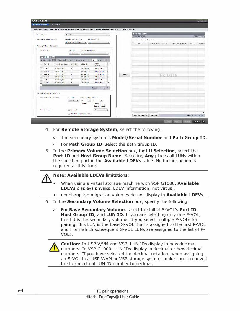
4. For Remote Storage System, select the following:
¢ The secondary system's Model/Serial Number and Path Group ID.¢ For Path Group ID, select the path group ID.
5. In the Primary Volume Selection box, for LU Selection, select thePort ID and Host Group Name. Selecting Any places all LUNs withinthe specified port in the Available LDEVs table. No further action isrequired at this time.
Note: Available LDEVs limitations:
• When using a virtual storage machine with VSP G1000, AvailableLDEVs displays physical LDEV information, not virtual.
• nondisruptive migration volumes do not display in Available LDEVs.6. In the Secondary Volume Selection box, specify the following:
a. For Base Secondary Volume, select the initial S-VOL's Port ID,Host Group ID, and LUN ID. If you are selecting only one P-VOL,this LU is the secondary volume. If you select multiple P-VOLs forpairing, this LUN is the base S-VOL that is assigned to the first P-VOLand from which subsequent S-VOL LUNs are assigned to the list of P-VOLs.
Caution: In USP V/VM and VSP, LUN IDs display in hexadecimalnumbers. In VSP G1000, LUN IDs display in decimal or hexadecimalnumbers. If you have selected the decimal notation, when assigningan S-VOL in a USP V/VM or VSP storage system, make sure to convertthe hexadecimal LUN ID number to decimal.
6-4 TC pair operationsHitachi TrueCopy® User Guide

b. For Selection Type, select the method for assigning S-VOLs whenmultiple primary volumes are selected.- With Interval, specify an interval the system skips betweensecondary system LU numbers.
c. - With Relative Primary Volume, the system assigns secondarysystem LU numbers based on proximity to P-VOL LU numbers.
7. Click Options to define the following optional settings:
a. For Primary Volume Fence Level, specify whether the primarysystem allows or rejects write operations to the P-VOL when the pairis split due to an error.- Data: The P-VOL cannot be written to.- Status: The P-VOL can be written to if the primary system canchange S-VOL status to PSUE; otherwise it cannot be written to.- Never: The P-VOL can always be written to.
b. For Initial Copy Type, specify whether to copy data from P-VOL toS-VOL during the operation.- Entire Volume creates the pair and copies data to the S-VOL.(Default)- None creates the pair but data is not copied to the S-VOL. Thisrequires that data in the P-VOL and S-VOL are already identical.
c. For Copy Pace, specify the number of tracks to be copied per remoteI/O during the operation. The range is 1 to 15; 15 is the default. Thisoption affects performance as follows:- 1 to 5 is slow, improves performance and lowers impact to host I/O.- 5 to 10 is medium.- 11 to 15 is fast, may lower performance and increase impact to hostI/O.
d. For Initial Copy Priority, specify the scheduling order for the initialcopy operation. The range is 1 to 256; 32 is the default.If a time-out error occurs during this operation, the order specified inInitial Copy Priority may not run as expected. A time-out error canoccur because of the CU configuration or data path error. Review theerror, delete the pair with an error, then retry the operation.
8. Back again in the Primary Volume Selection box, select the primaryvolume to be copied first and click Add. The volume and pair informationmoves to the Selected Pairs table.In the Selected Pairs table, you can change pair options by selecting itand clicking Change Settings. Remove a pair by selecting it and clickingRemove.
9. Click Finish.10. In the Confirm window, review the settings and enter a task name in the
Task Name box.11. Click Apply to save your settings.
TC pair operations 6-5Hitachi TrueCopy® User Guide

Splitting pairsYou can split a pair, which suspends data copying to the S-VOL.
When a pair is split:
• I/O writes from the host continue to the P-VOL, but stop to the S-VOL.• Any current update copy operation completes to the S-VOL, ensuring data
consistency to the point of the split operation.• Pair status changes to PSUS.• The primary system records the updated tracks to the P-VOL that occur
after the split as differential data. This data is copied to the S-VOL whenthe pair is resynchronized.
• You can set an option to block updates to the P-VOL while the pair is split.This results in the P-VOL and S-VOL staying synchronized.
• Another option is to enable system write to the S-VOL from a host. Thesecondary system records the updated tracks as differential bitmaps.When the pair is resynchronized, the secondary system sends thedifferential bitmaps to the primary system, which merges all differentialbitmaps to determine which tracks are out-of-sync.
Prerequisite information
• Pair status must be COPY or PAIR.
To split one or more pairs
1. On the Resources tab, expand the Storage Systems tree, right-clickthe target storage system and click Remote Replications.
2. In the Remote Replications window, click the TC Pairs tab, select thepair to be split then click Split Pairs.
3. In the Split Pairs window, ensure that the pair to be split appears in theSelected Pairs table.
6-6 TC pair operationsHitachi TrueCopy® User Guide

4. For Secondary Volume Write, specify whether the host can write to theS-VOL while the pair is split.
¢ Enable. Accepts host writes to the S-VOL. Note the following:- If you plan to resynchronize the pair after the S-VOL has beenwritten to while split, you must select Depend on Primary VolumeFence Level for the Primary Volume Write option, below. Thisensures that P-VOL and S-VOL bitmaps are merged when the pair isresynchronized.- If you specify Enable for this option, and also need the P-VOL tocontinue accepting host I/O, make sure to select Depend onPrimary Volume Fence Level for Primary Volume Write.Enable is only available when performing the split operation from thepair's primary storage system.
¢ Disable (default), to cause host input to be rejected by the S-VOLwhile the pair is split.
5. For Primary Volume Write, specify whether writing to the P-VOL isenabled while the pair is split.
¢ Depend on Primary Volume Fence Level: Writing to the P-VOL isbased on fence level specified during the Create Pairs operation. Thisis the default.
¢ Disable: Write I/Os to the P-VOL are rejected regardless of the fencelevel. Select this option to maintain synchronization of the P-VOL andS-VOL. Do not select this option if the P-VOL is necessary for hostsystem operations.Disable is only available when performing the split operation from thepair's primary storage system.
TC pair operations 6-7Hitachi TrueCopy® User Guide

6. Click Finish.7. In the Confirm window, review the settings and enter a task name in the
Task Name box.8. Click Apply to save your settings.
Resynchronizing pairsWhile a TrueCopy pair is split, the primary system does not perform updatecopy operations to the S-VOL. Resynchronizing the pair updates the S-VOLwith differential data accumulated since the split, so that its data is againidentical with the P-VOL's data. Update copy operations begin again to the S-VOL.
Prerequisite information
• Pair status must be PSUS or PSUE.• This operation is performed from the primary system only.
To resynchronize one or more pairs
1. On the Resources tab, expand the Storage Systems tree, right-clickthe target storage system and click Remote Replications.
2. In the Remote Replications window, click the TC Pairs tab then selectthe pairs to be resynchronized.
3. In the TC Pairs tab, click Resync Pairs.4. In the Resync Pairs window, ensure that the pair to be resynchronized
appears in the Selected Pairs table.
5. For Primary Volume Fence Level, specify whether the primary systemrejects write operations to the P-VOL when the pair is split due to anerror.
6-8 TC pair operationsHitachi TrueCopy® User Guide

¢ - Status: The P-VOL cannot be written to only if the primary systemis not able to change S-VOL status to PSUE.
¢ - Never: The P-VOL can always be written to.¢ - Data: The P-VOL cannot be written to.For more information, see Allowing I/O to the P-VOL after a split—FenceLevel options on page 3-9 .
6. For Copy Pace, specify the number of tracks to be copied during theinitial copy. The range is 1 to 15; 15 is the default. This option affectsperformance as follows:- 1 to 5 is slow, improves performance and lowers impact to host I/O.- 5 to 10 is medium.- 11 to 15 is fast, may lower performance and increase impact to hostI/O.
7. For Copy Priority, enter the priority, or scheduling order, for the resyncoperation. You can set priority from 1 to 256. The default is 32. For moreon priority, see the descriptions in Priority for initial copy operations andscheduling order on page 3-12.
8. Click Finish.9. In the Confirm window, review the settings and enter a task name in the
Task Name box.10. Click Apply to save your settings.
Deleting pairsA TrueCopy pair can be deleted. Doing this deletes the TC relationship,though not the volumes or their data.
• When it is no longer necessary to maintain a remote copy of the P-VOL,delete a pair from the primary system only. All update operations arestopped and pair status for both the P-VOL and S-VOL changes tounpaired.When a pair is deleted, the primary system continues to accept write I/Oto the former P-VOL but does not keep track of the updates.
• Delete a pair from the secondary system only for disaster recoverypurposes. When you do this, the secondary system changes the S-VOLpair status to unpaired, the primary system detects that the S-VOL statusis unpaired, and then changes P-VOL status to PSUS (Delete pair to RCU).To restart a pair that was deleted from the secondary system, you mustdelete the pair from the primary system, then create the pair from theprimary system.
Note: When you delete a pair from the secondary system, make sure thatthe S-VOL and P-VOL are identical, including the volume labels. Take allnecessary steps to prevent system problems due to duplicate volumes.
TC pair operations 6-9Hitachi TrueCopy® User Guide

To delete pairs
1. On the Resources tab, expand the Storage Systems tree, right-clickthe target storage system and click Remote Replications.
2. In the Remote Replications window, click the TC Pairs tab then selectthe pairs to be deleted.
3. In the TC Pairs tab, click More Actions > Delete Pairs.4. In the Delete Pairs window, ensure that the pairs to be deleted appear
in the Selected Pairs table.
5. For Delete Mode, specify one of the following:
¢ Normal: Deletes the pair only if the primary system can change bothP-VOL and S-VOL to unpaired volumes.
¢ Force: Forcibly deletes pairs even when the primary system cannotcommunicate with the secondary system.
6. Click Finish.7. In the Confirm window, review the settings and enter a task name in the
Task Name box.8. Click Apply to save your settings.
6-10 TC pair operationsHitachi TrueCopy® User Guide

7Monitoring and maintaining the TC
system
This chapter provides information and instructions for monitoring andmaintaining a TrueCopy system.
□ Monitoring pair status, license capacity
□ Monitoring TC pair synchronous rate
□ Monitoring TC operations history
□ Changing P-VOL Fence Level
□ Forcibly deleting pairs
□ Saving pair information to a text file
□ Monitoring and maintaining remote connections and paths
□ Deleting TrueCopy
□ Managing power-off for systems and network devices
□ Media maintenance
Monitoring and maintaining the TC system 7-1Hitachi TrueCopy® User Guide

Monitoring pair status, license capacityMonitoring the TrueCopy system is an ongoing operation that should beperformed frequently to keep track of and maintain your pairs.
• When you want to perform a pair operation, first check the pair's status.Each operation requires a specific status or set of statuses.
• Pair status changes when an operation is performed. Check status to seethat pairs are operating correctly and that data is updated from P-VOLs toS-VOLs in PAIR status, or that differential data management is performedin Split status.
Monitoring using the GUI is done manually. Monitoring should be repeatedfrequently. Email notifications of problems can be set up using the GUI.
To monitor pair status, license capacity
1. On the Resources tab, expand the Storage Systems tree, right-clickthe target storage system and click Remote Replications.
2. In the Remote Replications window, click the TC Pairs tab then selectthe pair volume with the status you want to review.
3. In the TC Pairs tab, click More Actions > View Pair Properties andreview Status.
7-2 Monitoring and maintaining the TC systemHitachi TrueCopy® User Guide

For more information, see Pair status definitions on page 7-3.
To monitor license capacity
1. See the Summary area in the Replications window.
How pair status changesThe primary system changes and maintains the status of the P-VOL and isresponsible for keeping the P-VOL and its S-VOL synchronized. The secondarysystem maintains the status of the S-VOL.
• The primary system can change the status of the P-VOL and S-VOL.• The secondary system can change the status of the S-VOL but not the P-
VOL. When an operation is performed from the secondary system, theprimary system detects a status change in the S-VOL and then changesP-VOL status accordingly.
• The status indicates the state of the volume or pair:
¢ When a pair is started, the secondary system changes the status ofthe P-VOL and S-VOL to COPY. When the initial copy operation iscomplete, the primary system changes the status of both volumes toPAIR.
¢ When you split a pair, the system changes the status of the P-VOLand S-VOL to PSUS.
¢ When a pair is suspended due to an error condition, the primary/secondary system changes the P-VOL and S-VOL status to PSUE.
¢ When a pair is deleted from the primary system, that system changesthe status of the P-VOL and S-VOL to unpaired.
¢ When a pair is deleted from the secondary system, that systemchanges the S-VOL status to unpaired, and the secondary systemdetects the pair release and changes the P-VOL status to PSUS.
Pair status definitionsBoth Device Manager - Storage Navigator and CCI pair status names appearin the Status column, except when the names are the same. When they arethe same, the CCI status does not appear.
The following table shows both types of status names and their descriptions.In some cases, a particular status has no exact parallel status in the otherinterface. This is noted.
When checking your pairs' status, click Refresh to make sure the data iscurrent. The P-VOL access and S-VOL access columns in the following tableindicate whether the volumes accept read/write.
Monitoring and maintaining the TC system 7-3Hitachi TrueCopy® User Guide

HDvM - SNstatus CCI status Description P-VOL
accessS-VOLaccess
Unpaired inHDvM - SN
SMPL This volume is not currently assigned to aTrueCopy pair.
Read/Write Read/Write
COPY1 COPY The initial copy operation for this pair is inprogress. This pair is not yet synchronized.
Read/Write Read Only
PAIR PAIR • The pair is synchronized• Updates from the host to the P-VOL are
duplicated in the S-VOL.
Read/Write Read Only
PSUS(See alsoSplit typeson page7-5.)
SSUS, PSUS • The pair was split by a user or deletedfrom the secondary system. The pair isnot synchronized.
• When you split the pair from the primarysystem, that system changes the statusof the P-VOL and S-VOL to PSUS.
• In PSUS status, updates to the S-VOLstop. The storage system keeps track ofupdates to the P-VOL in order to updatethe S-VOL when the pair isresynchronized.CCI also shows P-VOL status as PSUS.
• When you split the pair from thesecondary system, that system changesthe status of the S-VOL to PSUS. Theprimary system detects this and changesP-VOL status to PSUS.CCI shows the S-VOL status as SSUS.
• When you release the pair from thesecondary system, that system changesthe S-VOL status to SMPL. The primarysystem detects this and changes the P-VOL status to PSUS. The pair must bereleased from the primary system inorder to change P-VOL status to SMPL.
• CCI PSUS status indicates that althoughthe paired status is retained, the usersplit the pair. This status is only for theP-VOL. While the pair is split, the storagesystem keeps track of updates to the P-VOL in the differential bitmaps.
Read/Write Read only ifSecondaryVolumeWrittenoption isdisabled.Read/WriteifSecondaryVolumeWrittenoption isenabled.
PSUE(See alsoSplit typeson page7-5.)
PSUE • If the primary system cannot keep thepair synchronized for any reason, itchanges the status of the P-VOL and S-VOL (if possible) to PSUE.
• The pair is not synchronized.
Read/Write.Read only ifPrimaryVolumeFence Levelis Data.
Read Only
1 When pair status is COPY, neither cache nor shared memory can be added to or removed from thestorage system. When either of these tasks is to be performed, first split any pairs in COPY, status, thenresynchronize when the cache or shared memory operation is completed.
7-4 Monitoring and maintaining the TC systemHitachi TrueCopy® User Guide

Split types
This topic discusses pairs that are split by user operation (PSUS ), and pairsthat are suspended by the system because of failure (PSUE).
• You can split a pair when the initial copy operation is complete.
¢ You must split a pair to perform media maintenance on the P-VOL orto access the volume which Secondary Volume write option isenabled.
¢ When you split a pair, the primary system ensures synchronization bycompleting any pending update copy operation before changing thestatus to PSUS.
• Pairs are split by the primary system only, for any of the followingreasons:
¢ You released the pair from the secondary system.¢ An error condition related to the secondary system, the S-VOL, or an
update-copy operation.¢ The primary system cannot communicate with the secondary system.
Split types appear in the Status field on the View Pair Properties window. Thefollowing table describes the split types.
PSUS type Volumeapplies to Description
Primary Volumeby Operator
P-VOL The user split the pair from the primary systemspecifying Disable for Primary Volume Write. The S-VOLsplit type is "by Local Storage System"
SecondaryVolume byOperator
P-VOLS-VOL
The user split the pair from the primary or secondarysystem specifying Disable for Primary Volume Write.
by Local StorageSystem
S-VOL The secondary system received a request from theprimary system to split the pair. The P-VOL split typeis Primary Volume by Operator or Secondary Volume byOperator.
Release pair toRCU
P-VOL The primary system detected that the S-VOL statuschanged to SMPL because you released the pair from thesecondary system. The pair cannot be resynchronizedbecause the S-VOL does not have the PSUE/PSUS status.
by RemoteStorage System
P-VOLS-VOL
The primary system detected an error condition at thesecondary system (RCU), that caused the primarysystem to split the pair. The S-VOL split type is S-VOLFailure by Local Storage System.
S-VOL failure P-VOLS-VOL
The primary system detected an error duringcommunication with the secondary system, or an errorduring update copy. In this case, the S-VOL split type isusually S-VOL Failure. This split type is also used whenthe number of paths falls below the minimum number ofpaths setting on the Add Remote Connection window.
MCU IMPL P-VOL The primary system could not find valid controlinformation in its nonvolatile memory during IMPL. This
Monitoring and maintaining the TC system 7-5Hitachi TrueCopy® User Guide

PSUS type Volumeapplies to Description
S-VOL condition occurs only if the primary system is withoutpower for more than 48 hours (that is, power failure andfully discharged backup batteries).
Initial copy failed P-VOLS-VOL
The pair was split before the initial copy operation wascomplete. The data on the S-VOL is not identical to thedata on the P-VOL.
System behavior
Note the following behaviors for split pairs:
• The primary system stops performing update operations to the S-VOL. Itmay or may not continue accepting write I/Os to the P-VOL depending onthe P-VOL fence level setting.
• If an update fails, the primary system reports a unit check and notifiesthe host that Write fails. This ensures that both the host system andapplication program regard the write operation to the P-VOL as failed.
• If the primary system accepts subsequent write I/Os for a split P-VOL, thesystem records the updated data in the P-VOL tracks as differential data.When a split pair is resynchronized, the primary system copies the out ofsync P-VOL tracks to the S-VOL as differential data.
Monitoring TC pair synchronous rateYou can check on the percentage of synchronized data between the P-VOLand S-VOL.
To check a pair's synchronous rate
1. On the Resources tab, expand the Storage Systems tree, right-clickthe target storage system and click Remote Replications.
2. In the Remote Replications window, click the TC Pairs tab then selectthe pair whose rate you want to display.
3. In the TC Pairs tab, click More Actions > View Pair SynchronousRate.
7-6 Monitoring and maintaining the TC systemHitachi TrueCopy® User Guide

Clicking Refresh displays the latest synchronous rate.
Monitoring TC operations historyYou can review a pair's history of operations, including the operation'sdescription, date and time it took place, primary and secondary systeminformation, and other details.
To view a pair's operation history
1. On the Resources tab, expand the Storage Systems tree, right-clickthe target storage system and click Replication Dashboard.
2. In the Replication window, click View Histories > RemoteReplication.
3. In the Histories window, for Copy Type, click TC.
4. The Description column displays operations. They are explained below.
Note the following when viewing histories.
• Operation rows may not appear in descending, chronological order.• The most recent operations display, up to a maximum of 524,288
operations. Information older than seven days is not shown.• "LDEV ID" indicates the VSP G1000 physical LDEV ID, even when you use
CCI and use pair volumes in a virtual storage machine• If a failed split occurred with two or more LDEVs at the same time, the
number of pairs showing Pair Suspend (Failure) may not match the actualnumber of pairs in which the failure occurs.
Monitoring and maintaining the TC system 7-7Hitachi TrueCopy® User Guide

Operation descriptionsThe following table describes the operations shown in the Histories window.
Operation Displayed Description
Pair Add Start Creation of the pair started.
Pair Add Complete Creation of the pair completed.
Pair Delete The pair was deleted.
Pair Suspend (Operation) The pair was split.
Pair Suspend (Failure) The pair was split (suspended) because of afailure.
Pair Resync. start Resynchronization of the pair was started.
Pair Resync. Complete Resynchronization of the pair was completed.
Changing P-VOL Fence LevelYou can change the P-VOL's fence level, which specifies when to reject writeoperations to the P-VOL under certain failure circumstances.
For more information on fence levels, see Allowing I/O to the P-VOL after asplit—Fence Level options on page 3-9.
Prerequisite information
• Pair status must be COPY or PAIR.• The Edit Pair Options window is used for the following procedure. If you
select multiple pairs, the values do not display but are blank. When youchange a value, the change applies to all selected pairs
To change the fence level options
1. On the Resources tab, expand the Storage Systems tree, right-clickthe target storage system and click Remote Replications.
2. In the Remote Replications window, click the TC Pairs tab then selectthe pair whose options are to be changed.
3. In the TC Pairs tab, click More Actions > Edit Pair Options.4. In the Edit Pair Options window, for Primary Volume Fence Level
box, select the fence level for the pairs.- Never: The P-VOL can always be written to.- Data: The P-VOL cannot be written to.- Status: The P-VOL cannot be written to only if the primary system isnot able to change S-VOL status to PSUE.
7-8 Monitoring and maintaining the TC systemHitachi TrueCopy® User Guide

5. Click Finish.6. In the Confirm window, review the settings and enter a task name in the
Task Name box.7. Click Apply to save your settings in the system.
Forcibly deleting pairsYou forcibly delete a pair for the following reasons:
• A currently unpaired volume that was previously in a pair is unusablebecause previous pair information is still in the volume.
• The pair cannot be connected to the secondary system because of acommunication error. In this case, delete the pair forcibly in both primaryand the secondary systems.
Prerequisite information
• The volume must be unpaired.
To forcibly delete a pair
1. On the Resources tab, expand the Storage Systems tree, expand thetarget storage system and right-click Volume then click System GUI.
2. Click the LDEVs tab, then select the pair to be forcibly deleted.3. In the LDEVs tab, click More Actions > Force Delete Pairs (TC Pairs).4. In the Force Delete Pairs (TC Pairs) window, ensure that the volume is
in the Selected LDEV table.
Monitoring and maintaining the TC system 7-9Hitachi TrueCopy® User Guide

5. Click Apply.
Saving pair information to a text file You can save pair status and other information to a tab-delimited TSV file.
To save pair information
1. In the Remote Replication window, click More Actions > Export.2. If necessary, follow instructions in online Help.
Monitoring and maintaining remote connections and paths To view remote connection status and path information
1. View connection properties and path information by clicking ViewRemote Connection Properties in Remote Connection window.
7-10 Monitoring and maintaining the TC systemHitachi TrueCopy® User Guide

2. To check path and port information, from the Storage Systems tree,right- click the target storage system to select Remote Connections.Then click Connections (To) tab.Check connections under View Port Condition.
Check Status and other details in the Connections (To) tab.
Monitoring and maintaining the TC system 7-11Hitachi TrueCopy® User Guide

Remote path status definitionsThe following table provides remote path status descriptions.
Status Definition
Normal This path has been successfully established and can be used forTrueCopy remote copy activities.
InitializationFailed
The link initialization procedure with the secondary system hasfailed, because the physical path connection between either theprimary and secondary system, or between the primary system andthe host, was missing.
CommunicationTimeout
A timeout error has occurred between the primary and secondarysystem.
Path Rejected The remote path link function has been rejected by the secondarysystem. All remote path resources in the secondary system might beused for other connections.
Serial NumberMismatch
The serial number of the control unit that is connected to this remotepath does not match the serial number specified by the Add RemoteConnection window.
Invalid Port Mode The specified port does not have the initiator attribute.
RCU Port NumberMismatch
There are three possible causes:• The specified port in the secondary system is physically
disconnected from the primary system.• The port is not configured as an RCU target port.• The specified port number is not available.
RCU Port TypeMismatch
The microcode on the remote side does not support the fibre remotecopy function; or the specified port type is not RCU target.
CommunicationFailed
A timeout error has occurred on the path between the primary andsecondary system.
Logical Blockade This remote path was blockaded because a path error or a link erroroccurred continuously.
Program Error This remote path was blockaded because a program error occurred.
In Progress This remote path is in progress of changing the attribute of port.
7-12 Monitoring and maintaining the TC systemHitachi TrueCopy® User Guide

Configuring additional remote pathsYou can configure additional remote paths as needed. A maximum of eightremote paths are supported.
Prerequisite information
• Review the path-related prerequisites in Adding remote connection onpage 5-3.
To configure additional remote paths
1. On the Resources tab, expand the Storage Systems tree, right-clickthe target storage system and click Remote Connections.
2. In the Remote Connections window, click the Connections (To) tab.3. In the Connections (To) tab, select the remote connection where the
remote path is to be added.4. In the Connections (To) tab, click More Actions > Add Remote
Paths.5. In the Add Remote Paths window, add a new remote path by selecting
ports for the primary (left side) and secondary systems. You can makemultiple selections. To add paths, click Add Path.
6. Click Finish.7. In the Confirm window, review the settings and enter a task name in the
Task Name box.8. Click Apply to save your settings in the system.
Monitoring and maintaining the TC system 7-13Hitachi TrueCopy® User Guide

Changing minimum paths, round trip time, other remote connectionoptions
You can change remote connection options that affect how the system runsyour copy operations. These are:
• Number of minimum paths for a pair. You can find detailed information inDetermining Minimum Number of Remote Paths on page 3-6
• The interval for data transfer to complete (RIO MIH Time).• Round trip time, the time limit for copying data to the S-VOL. For more
information, see Determining Round Trip Time on page 3-4 for moreinformation.
To change remote connection options
1. On the Resources tab, expand the Storage Systems tree, right-clickthe target storage system and click Remote Connections.
2. Click the Connections (To) tab, the select the remote connection whoseoptions you want to change.
3. In the Connections (To) tab, click Edit Remote Connection Options.4. In the Edit Remote Connection Options window, for Minimum
Number of Paths, select the minimum number of paths between thesecondary and primary system.
5. For RIO MIH Time, enter an interval in seconds that, if exceeded, causesthe data-transfer operation to be reported as failed by the system. Therange is from 10 to 100 seconds; 15 is the default.
6. For Round Trip Time, enter a time limit for data copy from P-VOL to S-VOL. Range is 1-500 milliseconds.
7. Click Finish.8. In the Confirm window, review the settings and enter a task name in the
Task Name box.9. Click Apply to save your settings in the system.
7-14 Monitoring and maintaining the TC systemHitachi TrueCopy® User Guide

Deleting remote pathsYou can delete a remote path between a primary system and secondarysystem.
Prerequisite information
• Delete remote paths from the primary system.• Make sure that the remaining number of paths is equal to or greater than
the minimum number of paths setting on the Add Remote Connectionwindow, otherwise the delete path operation will fail.
To delete a remote path
1. On the Resources tab, expand the Storage Systems tree, right-clickthe target storage system and click Remote Connections.
2. In the Remote Connections window, click the Connections (To) tab.3. In the Connections (To) tab, select the remote connection with the path
to be deleted.4. Click More Actions > Remove Remote Paths.5. In the Remove Remote Paths window, click Remove for the remote
paths to be removed. Note that remote paths become unselectable whenthe minimum number of paths is reached.
6. Click Finish.7. In the Confirm window, review the settings and enter a task name in the
Task Name box.8. Click Apply to save your settings in the system.
Monitoring and maintaining the TC system 7-15Hitachi TrueCopy® User Guide

Deleting TrueCopyYou can delete the TrueCopy relationship between the primary and secondarysystems. This is done by deleting remote connections.
Prerequisite information
• All TC pairs must be deleted before removing the connection.• When the remote connection is deleted, all remote paths are deleted.• Deleting the TC relationship with a specific secondary system does not
affect TC operations between other primary systems and the secondarysystem.
• After a secondary system is deleted, you can reconfigure the remote pathto then connect another secondary system to the primary system. Youcan also delete the remote connection and reconfigure the primarysystem ports (initiator ports to ordinary target ports for fibre) to provideadditional host channels for the primary system.
To delete the TrueCopy relationship
1. On the Resources tab, expand the Storage Systems tree, right-clickthe target storage system and click Remote Connections.
2. In the Remote Connections window, click the Connections (To) tab.3. In the Connections (To) tab, select the remote connection to be
deleted.4. Click More Actions > Remove Remote Connection.5. In the Remove Remote Connection window, from the Selected
Remote Connection table, select the connection to be removed.
(You can review information about the connection by clicking Detail.)6. Click Apply.
7-16 Monitoring and maintaining the TC systemHitachi TrueCopy® User Guide

Managing power-off for systems and network devicesThough you are responsible for controlling power-off activities, it is advisableto check with your Hitachi Data Systems Support Center.
The following topics provide information for planned outages when TrueCopyis present.
General informationPlease review the following system behaviors regarding powering off:
• TC pairs are not affected when power is removed from a primary systemwhile operations are in progress.
• When power is restored on the primary system, the systemcommunicates with the secondary systems to confirm S-VOL pairstatus(es). Make sure that TC communications are fully restored (allpaths have normal status) before beginning I/O operations to the P-VOL.If primary system accepts an I/O for a P-VOL when path status is notnormal, primary system will split the pair. P-VOL status will change toPSUE-by RCU but primary system cannot change pair status of the S-VOL.
• If power is removed from a secondary system or from a data pathcomponent while TC operations are in progress, the primary systemdetects the communication failure, splits all affected pairs, and generatesSIMs reporting the failures. The primary system changes the P-VOL statusto Suspend-by RCU but cannot change the status of the S-VOLs.
• If a primary or secondary system is powered off and the backup batteriesare fully discharged while pairs are split, differential data is retained toSSD. In this unlikely case, primary system copies differential data tosecondary system when the pairs are resynchronized.
Planned outage of the primary systemA planned outage of the primary system does not affect TrueCopy.
Planned outage of the secondary system or remote pathYou must split the pairs in a secondary system prior to a planned outage ofthe system or to a data path component (for example, switch, channelextender).
To perform a planned outage of a secondary system or data pathcomponent
1. Identify the P-VOLs that are paired with S-VOL in the secondary systemthat is to be powered off.For data path outage, identify all P-VOLs in the primary system that usethe path or component to be powered off.You need to know the primary system, CU, and LDEV ID (port, GID, LUN)for each of the P-VOLs.
Monitoring and maintaining the TC system 7-17Hitachi TrueCopy® User Guide

2. Connect to each primary system that contains affected P-VOLs, and splitall affected pairs. Confirm the changed pair status.
3. Perform the planned outage of the secondary system or data path.4. When the secondary system is fully powered on and ready, resynchronize
the affected pairs at each primary system. Confirm the pair statuschanges.
Planned outage of both primary and secondary systemsWhen you plan an outage of a TrueCopy primary and secondary systems atthe same time, the primary system must be powered off first, and thenpowered on last.
To perform a planned outage of primary and secondary system
1. Perform the planned outage of the primary system first. Because aplanned outage does not affect pairs, nothing out of the ordinary must bedone regarding the TC system or operations. Do not power on theprimary system at this time.
2. If a secondary system to be powered off is connected to a primary systemthat is not powered off, split the pairs before powering off the secondarysystem. Confirm that the pair status changes.
3. Perform the planned outage of the secondary systems as described inPlanned outage of the secondary system or remote path on page 7-17.
4. Power on the secondary systems. Make sure that they are fullyoperational and ready to resynchronize operations before powering on theprimary system.
5. Power on the primary system, and make sure it is ready to resynchronizeoperations. If you split any pairs in step 2, you can also resynchronizethose pairs now.
Media maintenanceThe write operation with a normal permission to the P-VOL will be copied tothe S-VOL of the TrueCopy pair. The write operation with a diagnostic ordevice support permission completes in the P-VOL but does not be copied tothe S-VOL. Therefore, you must split the TrueCopy pair before you performthe media maintenance.
7-18 Monitoring and maintaining the TC systemHitachi TrueCopy® User Guide

8Data migration
This chapter discusses using TrueCopy to migrate data from one storagesystem to another.
□ Migration overview
Data migration 8-1Hitachi TrueCopy® User Guide

Migration overviewTrueCopy can be used to move data from one system to another. Data istypically migrated for the following reasons:
• To copy data to a new volume• To temporarily move data from an LU to accommodate other activities
(for example, to make repairs)• To relocate LUs in order to balance workloads and distribute I/O activity
evenly within or across storage systems
You do not need to use host migration software is unnecessary for datamigration when using TrueCopy. Also, TrueCopy data migration does notaffect the host.
In a data migration, the entire contents of a volume are copied to thesecondary volume (P-VOL to S-VOL). The volumes are identical when thecopy operation completes. The volumes are then usually released from theTrueCopy pair.
If you need to migrate data from other vendors' storage systems to a VSPG1000 system, contact your Hitachi Data Systems Support Center.
Migrating data1. Make sure that the data path is installed, and TrueCopy configuration
procedures are completed. See Chapter 5, TC configuration on page 5-1for details.
2. Vary the target volume (S-VOL) offline from all attached hosts. Thesource volume (P-VOL) can remain online.
3. In Device Manager - Storage Navigator, connect to the storage systemwhere the volume to be migrated is located. Create the TrueCopy pair orpairs. See Creating pairs on page 6-3 as needed.When pair status changes to PAIR, the operation is completed. You canmonitor the progress of the operation from the Remote Replicationwindow.
4. If you are not using CCI commands and host software to complete themigration, continue the following procedure to stop using the P-VOLs andswitch to the S-VOLs:
a. Stop all host updates to the P-VOLs.b. When all update activity to the P-VOLs has stopped, connect to the
primary system, select the correct CU, and release the TrueCopypairs.
c. If the P-VOL and S-VOL are attached to the same host, vary the P-VOL offline, then vary the S-VOL online. Use this order because the P-VOL and S-VOL have the same volume labels and cannot be online tothe same host at the same time.
d. If you want to keep the volumes synchronized, establish the sameTrueCopy pairs in the reverse direction using the None initial copyoption. If the original P-VOLs will be temporarily unavailable for
8-2 Data migrationHitachi TrueCopy® User Guide

update copy operations, you can split the new pairs (pairsplit-r) sothat the new primary system keeps track of changes.
e. Start the applications with the S-VOLs. When the original P-VOLsbecome available, you can resynchronize the pairs.
If the original P-VOL is temporarily unavailable for update copy operations,split the new pair so that the new primary system keeps track of changes.
Data migration 8-3Hitachi TrueCopy® User Guide

8-4 Data migrationHitachi TrueCopy® User Guide

9Disaster recovery
This chapter discusses disaster recovery.
□ Disaster recovery overview
□ Switching operations to the secondary site
□ Transferring operations back to the primary site
Disaster recovery 9-1Hitachi TrueCopy® User Guide

Disaster recovery overviewPreparing for disaster recovery involves the following major steps:
1. Identify the volumes and groups that contain important files and data fordisaster recovery.
2. Create TrueCopy pairs, paying special attention to the options in P-VOLFence Level Settings to ensure that the system responds the way youwant in the event of a failure (see Allowing I/O to the P-VOL after a split—Fence Level options on page 3-9 ).
3. Install and configure host failover software between the primary andsecondary sites.
4. Establish file and database recovery procedures. These procedures forrecovering volumes due to control unit failure must already be in place.
5. Make sure that the host system at the primary site is configured toreceive sense information from the VSP G1000 primary system (forexample, using CCI or SNMP). This must also be done at the secondarysite if a host is connected to it.
Note: Procedures for disaster recovery involve releasing pairs. However,when using CCI you can perform disaster recovery without releasing pairs. Todo this, when setting up TrueCopy, add remote paths between the secondarysystem Initiator ports and primary system RCU Target ports. Then add aremote connection from the secondary system CU to the primary system CU.Use the same path group ID as you used from the primary to secondarysystem connection.
Remote copy and disaster recovery procedures are complex. Consult yourHitachi Data Systems Support Center on sense-level settings and recoveryprocedures.
Sense information shared between sitesWhen the primary system splits a TrueCopy pair due to an error condition,the primary and secondary system send sense information with unit checkstatus to the appropriate hosts. This is used during disaster recovery todetermine the consistency of the S-VOL, and must be transferred to thesecondary site via the host failover software.
File and database recoveryFile recovery procedures for disaster recovery should be the same as thoseused for recovering a data volume that becomes inaccessible due to controlunit failure.
TrueCopy does not provide a procedure for detecting and retrieving lostupdates. To detect and recreate lost updates, you must check other currentinformation (for example, database log file) that was active at the primarysystem when the disaster occurred.
9-2 Disaster recoveryHitachi TrueCopy® User Guide

The detection and retrieval process can take some time. Your disasterrecovery scenario should be designed so that detection and retrieval of lostupdates is performed after the application has been started at the secondarysite.
You should prepare for file and database recovery using files for file recovery(for example, database log files that have been verified as current).
Switching operations to the secondary siteIf a disaster or failure occurs at the primary site, the first disaster recoveryactivity is to switch your operations to the secondary site. S-VOLs arerecovered individually based on the pair status and P-VOL fence levelinformation for each pair.
You can switch operations to the secondary site either by deleting pairs, thenreestablishing them when recovery is completed; or by not deleting pairs.Both methods are presented below.
To switch operations to the secondary site by deleting pairs
1. Record the pair status and fence level of each S-VOL.2. Analyze the consistency of the S-VOLs, based on pair status and Primary
Volume Fence Level setting in the Create TC Pairs window. See CheckingS-VOL consistency with the P-VOL on page 9-4.
3. Perform file recovery as needed.4. Split all pairs from the secondary system using one of the following
commands:
¢ CCI pairsplit¢ BCM YKSUSPND¢ PPRC CSUSPEND
5. Release all pairs using one of the following commands:
¢ CCI pairsplit -S¢ BCM YKRECOVER¢ PPRC CRECOVERIf you are not using these tools, connect to each secondary system withDevice Manager - Storage Navigator to split and release the pairs.
Note: When the S-VOL is no longer paired, it cannot be distinguished itfrom a non-TrueCopy volume. Use the appropriate means to change theS-VOL volume labels.
6. Complete file recovery procedures.7. Vary the S-VOLs online.8. At the secondary site, start critical host operations, with the previous S-
VOLs now the P-VOLs.
Disaster recovery 9-3Hitachi TrueCopy® User Guide
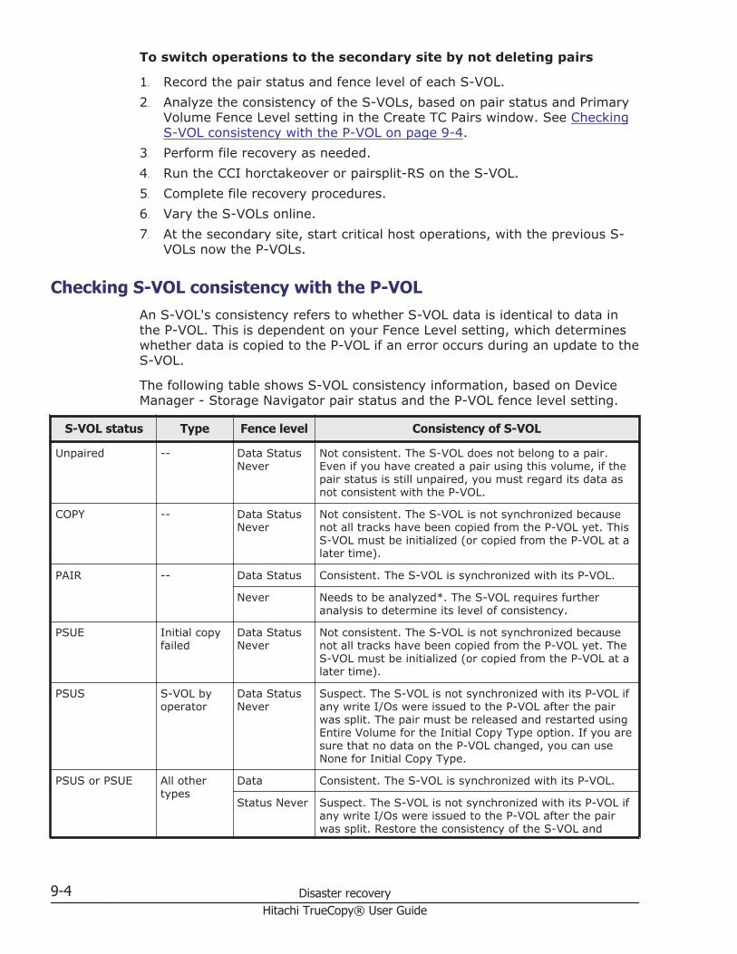
To switch operations to the secondary site by not deleting pairs
1. Record the pair status and fence level of each S-VOL.2. Analyze the consistency of the S-VOLs, based on pair status and Primary
Volume Fence Level setting in the Create TC Pairs window. See CheckingS-VOL consistency with the P-VOL on page 9-4.
3. Perform file recovery as needed.4. Run the CCI horctakeover or pairsplit-RS on the S-VOL.5. Complete file recovery procedures.6. Vary the S-VOLs online.7. At the secondary site, start critical host operations, with the previous S-
VOLs now the P-VOLs.
Checking S-VOL consistency with the P-VOLAn S-VOL's consistency refers to whether S-VOL data is identical to data inthe P-VOL. This is dependent on your Fence Level setting, which determineswhether data is copied to the P-VOL if an error occurs during an update to theS-VOL.
The following table shows S-VOL consistency information, based on DeviceManager - Storage Navigator pair status and the P-VOL fence level setting.
S-VOL status Type Fence level Consistency of S-VOL
Unpaired -- Data StatusNever
Not consistent. The S-VOL does not belong to a pair.Even if you have created a pair using this volume, if thepair status is still unpaired, you must regard its data asnot consistent with the P-VOL.
COPY -- Data StatusNever
Not consistent. The S-VOL is not synchronized becausenot all tracks have been copied from the P-VOL yet. ThisS-VOL must be initialized (or copied from the P-VOL at alater time).
PAIR -- Data Status Consistent. The S-VOL is synchronized with its P-VOL.
Never Needs to be analyzed*. The S-VOL requires furtheranalysis to determine its level of consistency.
PSUE Initial copyfailed
Data StatusNever
Not consistent. The S-VOL is not synchronized becausenot all tracks have been copied from the P-VOL yet. TheS-VOL must be initialized (or copied from the P-VOL at alater time).
PSUS S-VOL byoperator
Data StatusNever
Suspect. The S-VOL is not synchronized with its P-VOL ifany write I/Os were issued to the P-VOL after the pairwas split. The pair must be released and restarted usingEntire Volume for the Initial Copy Type option. If you aresure that no data on the P-VOL changed, you can useNone for Initial Copy Type.
PSUS or PSUE All othertypes
Data Consistent. The S-VOL is synchronized with its P-VOL.
Status Never Suspect. The S-VOL is not synchronized with its P-VOL ifany write I/Os were issued to the P-VOL after the pairwas split. Restore the consistency of the S-VOL and
9-4 Disaster recoveryHitachi TrueCopy® User Guide

S-VOL status Type Fence level Consistency of S-VOL
update it, if required. The time of suspension indicatedon the Last Update Time field of the Detailed Informationdialog box (MCU SVP time) will help to determine the lasttime the S-VOL was updated.
For pairs with a P-VOL fence level setting of Never, further analysis is required to determine the S-VOLconsistency. This can be determined by using sense information transferred via host failover, or bycomparing the contents of the S-VOL with other files that are confirmed to be consistent (for example,database log files). The S-VOLs should be recovered using the files that are confirmed to be consistent.Actual data recovery must be done using recovery point data in the database operation log.
Transferring operations back to the primary siteWhen host operations are running at the secondary site, the primary sitemust be restored and operations transferred back.
Create TrueCopy pair by specifying secondary site volume to primary volumeand primary site volume to secondary volume.
Select the appropriate procedure below based on whether you deleted pairsto switch operations to the secondary site, or ran the CCI Run horctakeoveror pairsplit-RS to the S-VOL command.
To transfer operations to the primary site—if pairs were deleted whenoperations were switched to the secondary site
1. At the primary site, bring up the host. Make sure that TC components areoperational.
2. At the primary system, release all pairs on the primary system.The Delete Pair by Force option must be used because the paired S-VOLsare in the SMPL state at the secondary site.
3. At the primary system, delete the TC association with the secondarysystems (Remove Remote Connection). In Device Manager - StorageNavigator, connect to each primary system to make sure that allsecondary systems are deleted.
4. At the primary and secondary systems, change path and port settings.- If you plan to use the same remote paths:
¢ At the primary system, change the existing initiator ports to RCUtarget ports.
¢ At the secondary system, change the existing RCU target ports toinitiator ports.
- To use the same switches, change the operating mode to the oppositedirection.- To use the same extenders, change the operating mode to the oppositedirection. The boxes/nodes connected to the primary system must be setto channel-mode, and the boxes/nodes connected to the secondarysystems must be set to device-mode.
5. At the secondary system, check that it is ready to create TrueCopy pair.
Disaster recovery 9-5Hitachi TrueCopy® User Guide

6. At the secondary system, create TrueCopy pair and synchronize S-VOLwith P-VOL. Make sure to use Entire Volume for the Initial Copy Typeoption. Confirm that the pairs are created and that status is PAIR.
7. At the secondary system, halt host operations and vary the P-VOL offline.This maintains synchronization of the pairs.
8. At the secondary system, split the pairs. Confirm that the pairs are splitand status is PSUS before proceeding. If an error occurs, resolve it beforeproceeding.
9. At the secondary system, release the pairs. You do not need to use theForce Delete Pairs (TC Pairs) option.
10. At the primary and secondary system, change the path and port settings.- If you plan to use the same data paths:
¢ At the primary system, change the existing RCU target ports toinitiator ports.
¢ At the secondary system, change the existing initiator ports to RCUtarget ports.
- To use the same switches, change the operating mode back to theoriginal direction.- To use the same channel extenders, change the operating mode back tothe original direction. The boxes/nodes connected to the primary systemmust be set to channel-mode, and the boxes/nodes connected to thesecondary systems must be set to device-mode.
11. At the primary system, check that it is ready to create TrueCopy pair.12. At the primary system, create TrueCopy pair. If all P-VOL and S-VOL are
synchronized, you may use None for the Initial Copy Type option. If P-VOL and S-VOL are not fully synchronized, use Entire Volume for InitialCopy Type.
13. Vary the primary system and P-VOLs online, and start host operations.
Below is the procedure to transfer operation back to the primary sitewithout deleting pairs.
1. At the primary site, bring up the host. Make sure that TC components areoperational.
2. Run the CCI pairresync-swaps to the S-VOL command. If the pair dataflow is already set in the opposite direction and the pair is in PAIR orCOPY status, the pairresync-swaps needs not to be run.
3. At the secondary system, halt host operations and vary the P-VOL offline.This maintains synchronization of the pairs.
4. Run the horctakeover to the P-VOL command.5. Vary the primary system and P-VOLs online, and start host operations.
9-6 Disaster recoveryHitachi TrueCopy® User Guide

10Troubleshooting
This chapter provides TrueCopy troubleshooting information.
□ Error codes and messages
□ General troubleshooting
□ Remote path status problems
□ Split pair problems
□ Troubleshooting using CCI
□ Service Information Messages (SIMs)
□ Pinned track recovery
□ Calling the Hitachi Data Systems Support Center
Troubleshooting 10-1Hitachi TrueCopy® User Guide

Error codes and messagesDevice Manager - Storage Navigator displays messages when error conditionsoccur during TrueCopy operations. The message describes the error andprovides a part code and error code.
The error message may also include a VSP G1000 error code. You may needto contact Hitachi Data Systems Support Center (see Getting help on pagexiii); please report the error codes. See Hitachi Command Suite User Guidefor a list of the error codes.
General troubleshootingThe following table provides a list of general errors.
Error Corrective action
The Device Manager - StorageNavigator computer hangs, orTrueCopy operations do not functionproperly.
• Make sure that the problem is not beingcaused by the PC or Ethernet hardware orsoftware, and restart the PC. Restarting theDevice Manager - Storage Navigator computerdoes not affect storage system operations.
• Make sure that all TrueCopy requirements andrestrictions are met (for example, same LUtype).
• Make sure that the primary and secondarysystem and data paths are powered on andfully operational (NVS, cache).
• Check all input values and parameters tomake sure that you entered the correctinformation about the Device Manager -Storage Navigator computer (for example,secondary system S/N and ID, pathparameters, P-VOL and S-VOL IDs).
An initiator channel-enabled LEDindicator (on the VSP G1000 controlpanel) is off or flashing.
Contact Hitachi Data Systems Support Center (seeGetting help on page xiii).
The pairs and/or remote systemsare not displaying correctly.
Make sure that the correct CU is selected.
A TrueCopy error message displayson the PC.
Resolve the error, and then try the TrueCopyoperation again.
The remote system path status isnot normal.
Check the path status (View Remote ConnectionProperties window), and see Remote path statusproblems on page 10-3.
Pair status is PSUE. See Split pair problems on page 10-5.
The paircreate or pairresyncoperation resulted in a timeouterror.
• Hardware failure: If the timeout error wascaused by a hardware failure, a SIM isgenerated. If this occurs, call servicepersonnel, then retry TrueCopy operationsafter the problem is fixed.
10-2 TroubleshootingHitachi TrueCopy® User Guide

Error Corrective action
• Heavy workload: If no SIM was generated,wait 5 or 6 minutes then check the pair'sstatus.- If status changed correctly, the failedoperation completed after the timeoutmessage was issued.- If the pair status did not change asexpected, heavy workload might haveprevented the operation from beingcompleted. Retry the operation when thesystem has a lighter workload.
• A communication error may have occurredbetween the Device Manager - StorageNavigator computer and SVP. See the HitachiCommand Suite User Guide for informationand instructions.
There is a pinned track on aTrueCopy volume.
See Pinned track recovery on page 10-17 formore information.
Monitoring data is not updatedthough the Monitoring Switch optionis set to Enable.
Because the time setting of SVP is changed, themonitoring data might not be updated. DisableMonitoring Switch, then enable again. For moreinformation about Monitoring Switch, see theHitachi Virtual Storage Platform G1000Performance Guide.
Remote path status problemsThe following table provides a list of remote path status problems.
Path status Description Corrective action
Normal This path has beensuccessfullyestablished and canbe used for TrueCopycopy activities.
None required.
InitializationFailed
The link initializationprocedure to theremote storagesystem failed becausethe physical pathconnection wasmissing between thelocal and remotestorage system.
• Make sure that the local and remotestorage systems are physically andcorrectly connected.
• Make sure that you entered the correctremote storage system S/N, ControllerID, and local and remote storage systemport numbers.
• Make sure the local and remote storagesystem ports are configured correctly.
CommunicationTime Out
Communicationbetween the local andremote storagesystem timed out.
• Make sure the remote storage system ispowered on and that NVS and cache arefully functional.
• Make sure that network relay devices areproperly configured and functional. This
Troubleshooting 10-3Hitachi TrueCopy® User Guide

Path status Description Corrective action
includes cables, connectors, switches,extender devices, communication lines,and all other devices connected to theextenders.
Port Rejected The local storagesystem rejected thelogical path linkcontrol functionbecause all logicalpath resources in thelocal storage systemare being used forother connections.
• Delete all paths and secondary systemsnot in use.
• Make sure that all local and remotestorage system ports are properlyconfigured: ordinary RCU target ports forremote storage systems, initiator portsfor local storage systems. If necessary,connect to the remote storage system todelete paths.
Serial NumberMismatch
The remote storagesystem's S/N doesnot match thespecified S/N.
• Make sure that you entered the correctremote storage system S/N andController ID, and local and remotestorage system port numbers.
• Make sure the local and remote storagesystem ports are configured correctly.
• Make sure that data path relay equipmentis properly configured and functional. Thisincludes cables, connectors, switches,extender devices, communication lines,and all other devices connected to theextenders.
Invalid Port The specified port isnot configured as aninitiator port, or thispath already exists.
• Make sure the correct port on the localstorage system is configured as aninitiator port.
• Make sure that no two paths betweenlocal and remote storage system portshave the same settings.
• Make sure that you entered the correctremote storage system S/N andController ID, and local and remotestorage system port numbers.
• Make sure that the local and remotestorage system ports are configuredcorrectly.
• Make sure that data path relay equipmentis properly configured and functional. Thisincludes cables, connectors, switches,extender devices, communication lines,and all other devices connected to theextenders.
Pair-Port NumberMismatch
The specified port inthe remote storagesystem is physicallydisconnected from thelocal storage system.
• Make sure that you specified the correctremote storage system port number.Correct the port number if necessary.
• Make sure that the cables between thelocal and remote storage system portsand between the local and remote storagesystem switches are connected correctly.
10-4 TroubleshootingHitachi TrueCopy® User Guide

Path status Description Corrective action
• Make sure that the topology settings ofthe local and remote storage systemports are correct.
Pair-Port TypeMismatch
The specified remotestorage system portis not configured asan RCU target port.
Make sure that the remote storage systemport is configured as an RCU target port.
CommunicationFailed
The local storagesystem connected tothe remote storagesystem successfully,but logicalcommunicationtimeout occurred.
• Make sure that the remote storagesystem port and the relay equipment areconfigured correctly.
• Make sure that data path relay equipmentis properly configured and functional. Thisincludes cables, connectors, switches,extender devices, communication lines,and all other devices connected to theextenders.
In Progress Paths are beingcreated or deleted, orthe port attribute isbeing changed.
Wait until processing is completed.
Path Blockade Blockaded due tocontinual path or linkfailure.
See the following.
The local storagesystem port does notwork.
Repair the port on the local storage system,then restore the path*.
The remote storagesystem port does notwork.
Repair the port on the remote storage system,then restore the path*.
The path relayequipment does notwork.
Repair the path relay equipment, then restorethe path*.
The connection cableis physically broken.
Replace the broken cable, then restore thepath*.
Program Error A program error isdetected.
Restore the path*.
* To restore a path, delete and then add the path again. It may be necessary to deleteand then add the secondary system again.To delete the secondary system or path, see Deleting TrueCopy on page 7-16 or Deletingremote paths on page 7-15. To re-register, see Adding remote connection on page 5-3.If you cannot restore the path after performing these operations, contact Hitachi DataSystems Support Center.
Split pair problemsThe following table provides a list of split pair problem types.
Troubleshooting 10-5Hitachi TrueCopy® User Guide

Pairstatus/
type
Appliesto Description Corrective action
PSUE (pairsuspended-error) / byRCU
P-VOL The primary systemdetected an errorcondition at thesecondary system, whichcaused the primarysystem to split the pair.The S-VOL split type is S-VOL Failure.
Clear the error condition at thesecondary system or S-VOL, thenresynchronize the pair from theprimary system.If you need to access the S-VOL toclear the error conditions, release thepair from the secondary system.After you clear the error conditionsfrom S-VOL, restart the pair.
PSUE / S-VOL Failure
P-VOL The primary systemdetected an error duringcommunication with thesecondary system, ordetected an I/O errorduring update copy. Inthis case, the split typefor the S-VOL is usuallyS-VOL Failure.
• Check the path status on theRemote Connections window. Iferrors occurred on the path,clear the error conditions.
• Clear any error conditions at thesecondary system or S-VOL,then resynchronize the pair fromthe primary system.
• If you need to access the S-VOLto clear the error conditions,release the pair from thesecondary system. After youclear the error conditions,recreate the pair.
PSUE (pairsuspended-error)/ MCUIMPL
P-VOL,S-VOL
The primary system couldnot find valid controlinformation in itsnonvolatile memoryduring the IMPLprocedure. This erroroccurs only if the systemis without power for morethan 48 hours (forexample, power failure orfully dischargedbatteries).
Resynchronize the pair from theprimary system. An entire initial copyoperation will be performed inresponse to the pairresync request.
PSUE /Initial CopyFailed
P-VOL,S-VOL
The primary system splitthis pair during the initialcopy operation. The dataon the S-VOL is notidentical to the data onthe P-VOL.
Release the pair from the primarysystem. Clear all error conditions onthe primary system, P-VOL,secondary system, and S-VOL.Recreate the pair.
Troubleshooting using CCIWhen an error occurs in pair operations using CCI, you can identify the causeof the error by referring to the CCI operation log file. This file is stored in thefollowing directory by default:
/HORCM/log*/curlog/horcmlog_HOST/horcm.log
10-6 TroubleshootingHitachi TrueCopy® User Guide

Where:
• * is the instance number.• HOST is the host name.
Example:
Error codes appear on the right of the equal symbol (=).
Review CCI error codes in the following topics.
• SSB2 error codes when SSB1 = 2E31/B901/B90A/B90B/B912/D004 onpage 10-7
• SSB2=B992 error codes when SSB1 = B901 or B90A on page 10-16
SSB2 error codes when SSB1 = 2E31/B901/B90A/B90B/B912/D004
Error code(SSB2) Description
4A96 The pair cannot be created because the specified P-VOL belongs to a different CLPRthan the registered consistency group CLPR.
4B02 A pair cannot be resynchronized because the specified consistency group does not havethe Open/MF attribute.
4BE0 The pair operation was rejected because the necessary shared memory is not mountedin the primary system.
9100 The command cannot be executed because the user authentication is not performed.
B920 The pair cannot be created because the system identifier is not correct (left-mostnumber in the 6-digit serial number).
B923 The command was rejected because supported micro code and non-supported microcode co-exist in DKC after receiving consistency group definition direction which isconfigured from several storage systems for pair creation and pair resync request.
B927 You cannot run the following operations to a pair in a 2DC configuration:Swap SuspendTakeover
B928 The pair cannot be created because the Mirror ID is invalid.
B929 The pair operation was rejected because the online microcode is being replaced.
B92A The pair cannot be created because the specified volume is a command device.
B934 The pair cannot be created because TC is not installed.
B935 S-VOL hide mode is not supported.
B936 The required shared memory for operating TrueCopy is not installed.
B93B The specified volume is a P-VOL. The pair cannot be released because the P-VOL isspecified as an S-VOL.
Troubleshooting 10-7Hitachi TrueCopy® User Guide

Error code(SSB2) Description
B941 The specified volume is an S-VOL. The pair cannot be released because the S-VOL isspecified as a P-VOL.
B945 The command was rejected because the volume is unpaired.
B952 The specified LU is not defined. The DKC configuration might have been changed.Restart CCI.
B97B The operation cannot run because pair status is either PSUS (by user) or PSUE (becauseof failure).
B97C The command was rejected because the volume is unpaired.
B990 The pair cannot be created because the consistency group number is greater than isallowed.If this error occurred when you did not specify the consistency group number, ContactHitachi Data Systems Support Center (see Getting help on page xiii).
B994 The Swap Resync operation cannot be performed because the S-VOL is not in PSUS orSSWS status. (Swap Resync resynchronizes differential data when the S-VOL isswapped for the P-VOL.)
B998 The pair cannot be created because the secondary system path setting is invalid.
B99B The pair cannot be created because TC Asynchronous is not supported.
B9BD The DKC LDEV configuration might have been changed while starting CCI. Restart CCI.
B9C0 The source of the command device has run out. In LUN Manager, set the commanddevice to OFF, then to ON.
C162 The pair cannot be resynchronized because the pair was not in the Suspend status.
C16B The pair cannot be created because the S-VOL is not available.
C184 A request for a Pairsplit-S operation was rejected because the status change of the S-VOL failed.
C189 A request for a Pairsplit-S operation was rejected because the pair status was invalid.
C18A A request for a Pairsplit-S operation was rejected because the corresponding volume orgroup was changing status.
C194 The pair cannot be split because the S-VOL pair status was in transition.
C195 A request for a Pairsplit-r operation was rejected because the pair status was alreadyPSUS (by user) PSUS (because of failure).
C198 Pair split cannot run because the group includes no pair that can be split.
C199 A request for a Pairsplit-r operation was rejected because the corresponding volume orgroup was changing status.
C1BE The pair's status cannot be changed during the power-on processing of the DKC.
C1D6 The command was rejected because it was issued to a non-TC volume.
C211 The command was rejected because the specified volume is a P-VOL. If the error occurswhen the volume is unpaired, select the volume in Device Manager - Storage Navigator,release the pair using the Force Delete Pairs (TC Pairs) window, and then run thecommand again.
10-8 TroubleshootingHitachi TrueCopy® User Guide

Error code(SSB2) Description
C212 The command was rejected because the specified volume is an S-VOL. If the erroroccurs when the volume is unpaired, select the volume in Device Manager - StorageNavigator, release the pair using the Force Delete Pairs (TC Pairs) window, and then runthe command again.
C214 The command was rejected because the secondary system is not registered, or theregistered information is invalid.
C215 The command was rejected because an internal logical error has occurred.
C218 The command was rejected because the pair status is invalid.
C21A The command was rejected because the P-VOL status is other than PSUS (by user)PSUS (because of failure).
C21C The command was rejected because the secondary system is not registered, or theregistered information is invalid.
C22A The command was rejected because the pair release was run on a volume other than P-VOL.
C22C The command was rejected because the volume is unpaired.
C22D The command was rejected because the specified volume is the volume other than theP-VOL.
C22E The command was rejected because the pairsplit command specifying -P option (writeprotection of P-VOL) was issued to a volume whose status is not PAIR.
C233 The command was rejected because the S-VOL status is unpaired.
C234/C235/C236/C237
The command was rejected because an internal logical error has occurred.
C238 The command was rejected because the specified volume is the volume other than theP-VOL.
C239 The command was rejected because the pair resync was operated on a volume whosestatus is other than PSUS (by user) PSUS (because of failure).
C23A The command was rejected because an internal logical error has occurred.
C23B The command was rejected because the volume is unpaired.
C23C The command was rejected because the volume status is other than PAIR or COPY.
C23D The command was rejected because the command for TC asynchronous was issued tothe TC asynchronous volume.
C267 The pair cannot be created because the command was issued to the command device.
C271 The command was rejected because the specified consistency group number is invalid.
C28B The command was rejected because the horctakeover command was issued to a volumewhose status is not SSWS.
C28C The command was rejected because the secondary system is not registered, or theregistered information is invalid.
C28D There is no volume to which the horctakeover command can run.
C28E The command was rejected because an internal logical error has occurred.
Troubleshooting 10-9Hitachi TrueCopy® User Guide

Error code(SSB2) Description
C297 The command was rejected because the specified volume is used as an S-VOL.
C2A0 The pair cannot be created because the capacity that is used by software products otherthan TC exceeds license capacity.
C2A1 The command was rejected because an internal logical error has occurred.
C2A3 The pair cannot be created because the used capacity exceeds the license capacity.
C2B3 The command was rejected because DP-VOL capacity is changing.
C2B4 The command was rejected because an internal logical error has occurred.
C2B5 The pair cannot be created because the TC P-VOL is being initialized by ShadowImage.
C2B6 The command was rejected because the releasing pages in DP-VOL is in progress.
C300 The TC pair associated with a UR pair cannot be created because the Disaster RecoveryExtended program product is not installed on the primary system.
C301 The TC pair associated with a UR pair cannot be created because the Disaster RecoveryExtended program product is not installed on the secondary system.
C304 The pair cannot be created because the S-VOL is a DP-VOL.
C305 The pair cannot be created because the capacity that is used by TC in the secondarysystem exceeds license capacity. Check license capacity, including for related softwareproducts.
C30D The volume in the secondary system or another volume that belongs to the same groupis changing to Simplex or Suspend status. Retry the operation after several minutes.
C312 The P-VOL is not in unpaired status.
C313 The P-VOL is not in PSUS or PSUE status.
C314 The P-VOL is not in unpaired status.
C315 The P-VOL includes PIN data.
C316 The P-VOL is in the process of drive copy for failure assistance.
C317 The P-VOL is in the process of drive copy for an SVP request.
C318 The P-VOL is terminating the copy task.
C319 The P-VOL is in the process of collection copy.
C31A The P-VOL is in the process of collection access.
C31B The P-VOL is blocked.
C31C The P-VOL is blocked and impossible to access.
C31D The P-VOL is being formatted.
C31E The P-VOL is read only.
C320 The number of remote paths between primary and secondary system is 0 (notspecified).
C321 The number of remote paths between primary and secondary system is smaller than theminimum required.
10-10 TroubleshootingHitachi TrueCopy® User Guide

Error code(SSB2) Description
C322 The DKC type of the primary system does not support TC.
C324 The secondary system's sequence number, SSID, or CU are invalid.
C327 The pair cannot be created because the P-VOL is not available for remote copy.
C328 The track formats of the P-VOL and the S-VOL do not match.
C32A The S-VOL is protected by the Data Retention Utility.
C32B The P-VOL is protected by the Data Retention Utility.
C32C The S-VOL is protected by the Data Retention Utility.
C32D The S-VOL is protected by the Data Retention Utility.
C32E A request for a Paircreate operation was rejected because the specified secondarysystem is an unsupported product.
C32F The number of P-VOL cylinders is not the same or smaller than the number of S-VOLcylinders.)
C330 The pair cannot be created or resynchronized because P-VOL and S-VOL capacities arenot the same, or because the S-VOL is in a LUSE configuration.
C332 S-VOL cache is unavailable.
C333 S-VOL DFW is disabled.
C335 The S-VOL is the TC P-VOL.
C336 The S-VOL includes PIN data.
C337 The S-VOL is in reserve status.
C338 Copy pair cannot be created because of the either of the following reasons.• The S-VOL is in the intervention-required condition, protected, or unusable status.• The S-VOL is the S-VOL or Reserved volume of ShadowImage, Reserved volume of
Volume Migration, or the volume of UR pair.
C339 The S-VOL is not available.
C33A A request for a Paircreate operation was rejected because the secondary system is a notsupported by TC.
C33B The corresponding volume cannot be specified as an S-VOL because the volume is usedas another pair's S-VOL.
C33C A request for a Paircreate operation was rejected because the specified S-VOL was notmounted.
C33E The pair cannot be created because the S-VOL is not implemented or is blocked (DEVNOT READY status).
C33F The corresponding volume cannot be specified as an S-VOL because the volume isalready specified as a TC pair volume.
C35C The P-VOL is not accessible.
C370 There are fewer paths than the required minimum following a path failure or because aninvalid path was specified.
Troubleshooting 10-11Hitachi TrueCopy® User Guide
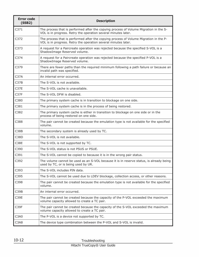
Error code(SSB2) Description
C371 The process that is performed after the copying process of Volume Migration in the S-VOL is in progress. Retry the operation several minutes later.
C372 The process that is performed after the copying process of Volume Migration in the P-VOL is in progress. Retry the operation several minutes later.
C373 A request for a Paircreate operation was rejected because the specified S-VOL is aShadowImage Reserved volume.
C374 A request for a Paircreate operation was rejected because the specified P-VOL is aShadowImage Reserved volume.
C379 There are fewer paths than the required minimum following a path failure or because aninvalid path was specified.
C37A An internal error occurred.
C37B The S-VOL is not available.
C37E The S-VOL cache is unavailable.
C37F The S-VOL DFW is disabled.
C380 The primary system cache is in transition to blockage on one side.
C381 The primary system cache is in the process of being restored.
C382 The primary system cache is either in transition to blockage on one side or in theprocess of being restored on one side.
C388 The pair cannot be created because the emulation type is not available for the specifiedvolume.
C38B The secondary system is already used by TC.
C38D The S-VOL is not available.
C38E The S-VOL is not supported by TC.
C390 The S-VOL status is not PSUS or PSUE.
C391 The S-VOL cannot be copied to because it is in the wrong pair status.
C392 The volume cannot be used as an S-VOL because it is in reserve status, is already beingused by TC, or is being used by UR.
C393 The S-VOL includes PIN data.
C395 The S-VOL cannot be used due to LDEV blockage, collection access, or other reasons.
C398 The pair cannot be created because the emulation type is not available for the specifiedvolume.
C39B An internal error occurred.
C39E The pair cannot be created because the capacity of the P-VOL exceeded the maximumvolume capacity allowed to create a TC pair.
C39F The pair cannot be created because the capacity of the S-VOL exceeded the maximumvolume capacity allowed to create a TC pair.
C3A0 The P-VOL is a device not supported by TC.
C3A8 The device type combination between the P-VOL and S-VOL is invalid.
10-12 TroubleshootingHitachi TrueCopy® User Guide

Error code(SSB2) Description
C3AA The secondary system's cache is blocked on one side.
C3AB The secondary system's cache is blocked on one side.
C3AC TC is not supported for this controller emulation type of the secondary system.
C3AD The secondary system capacity exceeds the license capacity.
C3AE TC is not installed on the secondary system.
C3AF The DKC type of the secondary system is not supported by TC.
C3B1 The number of paths is smaller than the required minimum number of paths.
C3B3 An internal error occurred.
C3B5 The configuration combination of P-VOL and S-VOL is invalid
C3B6 The P-VOL is an SI volume.
C3B7 The S-VOL is an SI volume.
C3B8 An internal error occurred.
C3B9 The pair cannot be created for one of the following reasons.• LUN is not defined for the S-VOL.• The S-VOL is a mainframe volume.• The S-VOL is an intermediate volume.• The emulation type is not supported for the S-VOL.
C3BC TC is not installed on the secondary system.
C3BE The following volumes cannot be specified as a TC P-VOL:• SI S-VOL not in PSUS status• SI P-VOL in the process of reverse copy
C3BF A TC S-VOL cannot be specified as an SI S-VOL, reserved volume, or P-VOL in theprocess of reverse copy.
C3C7 A request for a Paircreate operation was rejected because the specified volume wasalready part of a TC or UR pair (including journal volumes).
C3CA The S-VOL is reserved; or a secondary system, S-VOL, or the path between primarysystem and secondary system is in the BUSY status.
C3CD The S-VOL is an SI volume.
C3D2 The DKC type of the secondary system is not supported by TC.
C3D4 A pair cannot be created because the P-VOL is being used by Volume Migration.
C3D6 The specified S-VOL is unavailable because the connecting port cannot recognize it.
C3D7 The pair status of the S-VOL is invalid.
C3D8 The pair cannot be created because the volume specified for the S-VOL is a systemvolume.
C3D9 The pair cannot be created if the TC S-VOL corresponds to any of the following:The volume is a DP-VOL; the pair using the volume is an SI, Thin Image, or Copy-on-Write Snapshot pair, or a Volume Migration reserve volume.
Troubleshooting 10-13Hitachi TrueCopy® User Guide

Error code(SSB2) Description
The volume is a DP-VOL and an addition to volume capacity is in progress, or pages arebeing released.The capacity of the volume is different from the capacity of the P-VOLThe volume is initialized by SI
C3DB S-VOL pair status is not PSUS or PSUE.
C4DE The pair cannot be created because the remote path is not valid.
C4FC The required amount of shared memory for the operation is not installed in thesecondary system.
CB12 TC, TCz, UR, and URz cannot be mixed in the consistency group.
CB19 The secondary system consistency group cannot be deleted because the horctakeovercommand reversing operations between the P-VOL and S-VOL failed.
CB1A The secondary system consistency group was abnormally terminated because thehorctakeover command reversing operations between the P-VOL and S-VOL failed.
CB1D No dummy volume can be created in the S-VOL.
CB1F The secondary system does not support TC.
CB20 In referring to the function bit, the system information reference was abnormallyterminated.
CB21 In a Pairresync operation, all difference setting was abnormally terminated.
CB23 An internal error occurred.
CB5D The command was rejected because after receiving pair creation request, since it isconnected to old model, specified P-VOL became out of support.
CB60 TC is not installed in the secondary system.
CB62 One DKC cannot include a pair using Escon and a pair using Fibre.
CB66 The required differential area is not available in the secondary system.
CB67 An additional shared memory is not installed in the secondary system.
CB68 The required differential area is not available in the primary system.
CB69 The number of pairs exceeds the maximum number that can be created in a singleconsistency group.
CB6E The Paircreate operation cannot run because the P-VOL is an external storage systemvolume.
CB6F The Paircreate operation cannot run because the S-VOL is an external storage systemvolume.
CB71 The Paircreate operation cannot run because the P-VOL is an external storage systemmigration volume.
CB73 The Paircreate operation cannot run because the S-VOL is an external storage systemmigration volume.
CB75 The device is not recognized correctly.
CB76 The Paircreate operation cannot run because the paths are specified per storagesystem.
10-14 TroubleshootingHitachi TrueCopy® User Guide
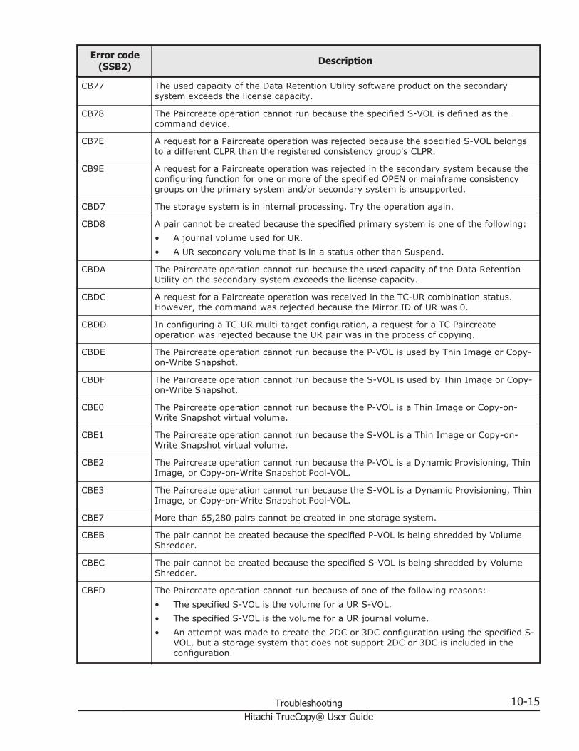
Error code(SSB2) Description
CB77 The used capacity of the Data Retention Utility software product on the secondarysystem exceeds the license capacity.
CB78 The Paircreate operation cannot run because the specified S-VOL is defined as thecommand device.
CB7E A request for a Paircreate operation was rejected because the specified S-VOL belongsto a different CLPR than the registered consistency group's CLPR.
CB9E A request for a Paircreate operation was rejected in the secondary system because theconfiguring function for one or more of the specified OPEN or mainframe consistencygroups on the primary system and/or secondary system is unsupported.
CBD7 The storage system is in internal processing. Try the operation again.
CBD8 A pair cannot be created because the specified primary system is one of the following:• A journal volume used for UR.• A UR secondary volume that is in a status other than Suspend.
CBDA The Paircreate operation cannot run because the used capacity of the Data RetentionUtility on the secondary system exceeds the license capacity.
CBDC A request for a Paircreate operation was received in the TC-UR combination status.However, the command was rejected because the Mirror ID of UR was 0.
CBDD In configuring a TC-UR multi-target configuration, a request for a TC Paircreateoperation was rejected because the UR pair was in the process of copying.
CBDE The Paircreate operation cannot run because the P-VOL is used by Thin Image or Copy-on-Write Snapshot.
CBDF The Paircreate operation cannot run because the S-VOL is used by Thin Image or Copy-on-Write Snapshot.
CBE0 The Paircreate operation cannot run because the P-VOL is a Thin Image or Copy-on-Write Snapshot virtual volume.
CBE1 The Paircreate operation cannot run because the S-VOL is a Thin Image or Copy-on-Write Snapshot virtual volume.
CBE2 The Paircreate operation cannot run because the P-VOL is a Dynamic Provisioning, ThinImage, or Copy-on-Write Snapshot Pool-VOL.
CBE3 The Paircreate operation cannot run because the S-VOL is a Dynamic Provisioning, ThinImage, or Copy-on-Write Snapshot Pool-VOL.
CBE7 More than 65,280 pairs cannot be created in one storage system.
CBEB The pair cannot be created because the specified P-VOL is being shredded by VolumeShredder.
CBEC The pair cannot be created because the specified S-VOL is being shredded by VolumeShredder.
CBED The Paircreate operation cannot run because of one of the following reasons:• The specified S-VOL is the volume for a UR S-VOL.• The specified S-VOL is the volume for a UR journal volume.• An attempt was made to create the 2DC or 3DC configuration using the specified S-
VOL, but a storage system that does not support 2DC or 3DC is included in theconfiguration.
Troubleshooting 10-15Hitachi TrueCopy® User Guide

Error code(SSB2) Description
CBEE The pair was not created because the specified P-VOL is part of a UR pair for deltaresync.
CBF3 The pair cannot be created because the volume specified as the P-VOL is used as anexternal volume for nondisruptive migration and Cache Through is set as the cachemode.
CBF4 The pair cannot be created because the S-VOL is used as the external volume mappedfor online data migration.
CBF7 An attempt was made to create the 2DC or 3DC configuration using the specified P-VOL,but the Paircreate operation cannot run because a storage system that does not supportthe 2DC or 3DC configuration is included.
CBF8 The pair cannot created because the model or the microcode version of the primary orsecondary system is not supported.
CBFC The pair cannot be created because the consistency group number is not within thesupported range.
CBFF The pair cannot be created because the remote path is not valid.
FD01 The pair cannot be created because no virtual LDEV ID is specified for the volumespecified as the S-VOL.
FD02 The pair cannot be created because no virtual LDEV ID is specified for the volumespecified as the P-VOL.
FD03 The pair cannot be created because the specified virtual information does not match thevirtual information registered in the secondary storage system.
FD04 The specified secondary storage system does not support global storage virtualization.
FD05 The specified primary storage system does not support global storage virtualization.
FD06 The pair cannot be created because the volume specified as the P-VOL is used as anexternal volume for nondisruptive migration and also used as a volume for a VolumeMigration pair.
FD07 The pair cannot be created because volume specified as P-VOL is used by GAD pair.
FD08 The pair cannot be created because volume specified as S-VOL is used by GAD pair.
FD09 The pair cannot be created because volume specified as P-VOL is a GAD reservevolume.
FD0A The pair cannot be created because volume specified as S-VOL is a GAD reservevolume.
SSB2=B992 error codes when SSB1 = B901 or B90A
ErrorCode
(SSB1)
ErrorCode
(SSB2)Description
B901 B992 Pair cannot be created because DKC type dose not support TCAsynchronous.
10-16 TroubleshootingHitachi TrueCopy® User Guide

ErrorCode
(SSB1)
ErrorCode
(SSB2)Description
B90A B992 Consistency group information cannot be retrieved because TCor UR is not installed.
Service Information Messages (SIMs)The VSP G1000 generates a service information message (SIM) to notifyusers of a possible service requirement for the storage system. SIMs can begenerated by the system's channel and storage path microprocessors or theservice processor (SVP). The SVP reports all SIMs related to TrueCopyoperations.
SIMs are classified according to the following severities: service, moderate,serious, or acute.
All SIMs are recorded on the VSP G1000 SVP and displayed in the DeviceManager - Storage Navigator Status window.
During TrueCopy operations, the primary and secondary system generate aservice SIM when P-VOL or S-VOL pair status changes for any reason,including normal status transitions (for example, COPY to PAIR).
• SIMs generated by the primary system include the P-VOL device ID (byte13).
• SIMs generated by the secondary system include the S-VOL device ID(byte 13).
If SNMP is installed and operational for the VSP G1000, each SIM results inan SNMP trap being sent to the appropriate hosts.
For further information about SNMP operations and SIMs, see the HitachiCommand Suite User Guide, or contact your Hitachi Data Systems SupportCenter.
Pinned track recoveryThis procedure ensures the pair's full data integrity while recovering thepinned track.
To recover a pinned track
1. Connect to the primary system of the pair containing a volume with thepinned track.
2. Release the pair that contains the volume with the pinned track.3. Perform your usual procedure for recovering data from a pinned track.
See the pinned track recovery procedures for your OS, or contact yourHitachi Data Systems Support Center in recovering the pinned track.
Troubleshooting 10-17Hitachi TrueCopy® User Guide

4. Recreate the pair from Create TC Pairs Window. Make sure to use theEntire Volume in the Initial Copy Type option.
Calling the Hitachi Data Systems Support CenterIf you need to call the Hitachi Data Systems Support Center, please provideas much information about the problem as possible, including:
• The circumstances surrounding the error or failure.• The content of any error messages displayed on the host systems.• The content of any error messages displayed on Device Manager -
Storage Navigator.• The Device Manager - Storage Navigator configuration information (use
the Dump Tool).• The service information messages (SIMs), including reference codes and
severity levels, displayed by Device Manager - Storage Navigator.
The HDS customer support staff is available 24 hours a day, seven days aweek. If you need technical support, log on to the HDS Support Portal forcontact information: https://hdssupport.hds.com
10-18 TroubleshootingHitachi TrueCopy® User Guide
ATC CLI reference
This appendix provides commands and options for command line userinterfaces and the Device Manager - Storage Navigator gui.
Commands and options for configuring, operating, monitoring, andmaintaining TrueCopy pairs, and for working with consistency groups, areprovided for HDvM - SN, CCI, BCM, and PPRC.
□ Configuration commands and options
□ Pair operation commands and options
□ Monitoring commands and options
□ Maintenance commands and options
□ Consistency group commands and options
TC CLI reference A-1Hitachi TrueCopy® User Guide

Configuration commands and optionsThe following table shows the commands and options for configuring TC.
For information about CCI commands, see the Hitachi Command ControlInterface Command Reference.
Operation Option Avail. in HDvM -SN?
CCIcommand and options
Edit Ports Port Attribute Yes raidcom modify port-port_attribute port attribute
Add RemoteConnection
Connection Type Yes none
Remote StorageSystem
Yes raidcom add rcu-rcu serial# mcu# rcu# id
Remote Paths Yes raidcom add rcu-cu_free serial# id pid
RIO MIH Time Yes raidcom modify rcu-rcu_option mpth rto rtt[fzd|fze]
Edit Remote ReplicaOptions
Copy Type Yes none
Maximum Initial CopyActivities
Yes none
Path Blockade Watch Yes none
Pair operation commands and optionsThe following table shows the commands and options for performing TC pairoperations.
Operation Option Avail. in HDvM- SN?
CCIcommand and options
Create TC Pairs Copy Type Yes paircreatenone
LU Selection Yes paircreatenone
CTG ID Yes paircreate-f[g] fence [CTGID]
Initial Copy Type Yes paircreate[-nocopy | -nocsus]
Initial Copy Priority Yes paircreatenone
Error Level Yes paircreate-nomsg
A-2 TC CLI referenceHitachi TrueCopy® User Guide

Operation Option Avail. in HDvM- SN?
CCIcommand and options
Split Pairs Secondary Volume Write Yes pairsplit-rw
Resync Pairs none No pairresync-nomsg
Delete Pairs none Yes pairsplit -S
Monitoring commands and optionsThe following table shows the commands and options for viewing TC pairinformation.
Operation Options Avail. in HDvM -SN?
CCIcommand and
options
View Pair Properties none Yes pairdisplay-m mode
View Pair Synchronous Rate none Yes pairdisplay-m mode
View Remote Connection Properties none Yes pairdisplay-m mode
Maintenance commands and optionsThe following table shows the commands and options for maintaining TCpairs.
Note: Maintenance commands and options are not available from CCI.
Operation Options Available in HDvM - SN?
Edit Pair Options none No
Edit Remote Connection Options RIO MIH Time Yes
Add Remote Paths none Yes
Remove Remote Paths none Yes
Remove Remote Connections none Yes
TC CLI reference A-3Hitachi TrueCopy® User Guide

Consistency group commands and optionsThe following table shows the commands and options for setting up andmanaging consistency groups for TC.
Note: Consistency group commands and options are not available from HDvM- SN.
Operation CCIcommand name
Reserve CTGs paircreate-f[g] fence[CTGID]
Add pair to the CTG paircreate-f[g] fence[CTGID]
Split pairs in CTG (no reservation time) pairsplit
-S 1
Resync pairs in CTG pairresync-f[g] fence[CTGID]
Delete pairs in CTG pairsplit-S
1. If you want to split multiple pairs simultaneously, you must make the pairs be a part of the sameconsistency group.
A-4 TC CLI referenceHitachi TrueCopy® User Guide
BTC GUI reference
This appendix describes Device Manager - Storage Navigator windows andfields used for TrueCopy. The following key topics are covered:
Important: Procedures in this manual are tailored to the Device Manager -Storage Navigator (HDvM - SN) GUI. When using this GUI, "Local StorageSystem" displays for the system you have accessed on the HDvM - SN server.
As a result, if you access the secondary site's HDvM - SN server, the GUIdisplays information for the pair's remote (secondary) system under "LocalStorage System". Likewise, the GUI in this case identifies the storage systemconnecting to the accessed system as the "Remote Storage System".
However, this manual uses the terms "primary storage system" or "primarysystem" for the storage system in which the primary volume (P-VOL) islocated in the primary site, and "secondary storage system" or "secondarysystem" for the storage system in which the secondary volume (S-VOL) islocated in the secondary site, unless otherwise noted.
□ Replication window
□ Remote Replication window
□ Remote Connections window
□ Add Remote Connection wizard
□ View Remote Connection Properties window
□ Remove Remote Connection window
□ Edit Remote Connection Options wizard
□ Add Remote Paths wizard
TC GUI reference B-1Hitachi TrueCopy® User Guide

□ Remove Remote Paths wizard
□ Edit Remote Replica Options wizard
□ Create Pairs wizard
□ Split Pairs wizard
□ Resync Pairs wizard
□ Delete Pairs wizard
□ Force Delete Pairs (TC Pairs) window
□ Edit Pair Options wizard
□ View Pair Properties (Remote) window
□ View Pair Synchronous Rate window
□ Histories window
B-2 TC GUI referenceHitachi TrueCopy® User Guide

Replication windowUse this window to view information about pairs and pair volumes.
In this topic, you can view the following tables.
• Summary section on page B-3• Replica LDEVs tab on page B-4
Summary section
Item Description
Licensed Capacity (Used/Licensed)
Used capacity and licensed capacity for each local andremote replication program product.
Number of Replica LDEVs Number of LDEVs used in replication.
Number of FCv2/FCSErelationships
Number of Compatible FlashCopy(R) V2 and CompatibleSoftware for IBM® FlashCopy® SE relationships.
Number of differentialtables
Number of differential tables in use.
View Histories - LocalReplication
Clicking opens the Histories window for local replication.
View Histories - RemoteReplication
Clicking opens the Histories window for remote replication.
Edit Options - LocalReplication
Clicking opens the Edit Local Replica Options window.
TC GUI reference B-3Hitachi TrueCopy® User Guide

Item Description
Edit Options - RemoteReplication
Clicking opens the Edit Remote Replica Options window.
Edit Options - SCP Time Clicking opens the Edit SCP Time window.
Replica LDEVs tab
Item Description
LDEV ID LDEV identifier. Clicking the link opens the LDEV Propertieswindow.
LDEV Name LDEV name.
Emulation Type LDEV's emulation type.
Capacity LDEV's capacity.
Copy Type Copy and volume type of the pair.• SI-L1: ShadowImage L1 pair• SI-L2: ShadowImage L2 pair• SIMF: ShadowImage for Mainframe• TI: Thin Image• FCv2: Compatible FlashCopy® V2• FCSE: Compatible Software for IBM® FlashCopy® SE• TC: TrueCopy• TCMF: TrueCopy for Mainframe• UR: Universal Replicator• URMF: Universal Replicator for Mainframe• GAD: global-active device
Virtual Storage Machine* Information about the LDEV's virtual storage machine andabout the LDEV.• Model type/Serial number: Model type and serial
number.• LDEV ID: Volume's virtual LDEV identifier.• Device Name: Volume's virtual device name, in the
format:virtual emulation type/number of virtual LUSE volumes/virtual CVS attribute- Only attributes that are specified display.- "CVS" displays at the end of the device name, if thevirtual CVS attribute is specified.- A blank indicates no values are specified.
• SSID: Volume's virtual SSID. A blank indicates that novirtual SSID is specified.
Export Clicking opens the window for exporting the tableinformation.
B-4 TC GUI referenceHitachi TrueCopy® User Guide

Item Description
* This item does not appear in the window by default. To display this item, change theColumn Settings option for the table.
Remote Replication windowUse this window to view information about remote replication pairs andmirrors (UR/URz only).
In this topic, you can view the following tables.
• Summary section on page B-5• TC Pairs tab on page B-6• UR Pairs tab on page B-8• Mirrors tab on page B-10• GAD Pairs tab on page B-12
Summary section
Item Description
Number of Pairs Number of pairs for each remote replication product and thetotal of all pairs.
Number of Mirrors UR/URz onlyNumber of open and mainframe mirrors and the total of allmirrors.
TC GUI reference B-5Hitachi TrueCopy® User Guide

TC Pairs tab
Item Description
Local Storage System Information about volumes in the accessed storage system.• LDEV ID: LDEV identifier. Clicking the link opens the
LDEV Properties window.• LDEV Name: LDEV name.• Port ID: Port identifier. TC only.• Host Group Name: Host group name. TC only.• LUN ID: LUN identifier. TC only.• Pair Position: Whether the volume is a primary or
secondary volume.• Provisioning Type1: Volume's provisioning type.• Emulation Type1: Volume's emulation type.• Capacity1: Volume's capacity.• CLPR1: Volume's CLPR.• Encryption1: Encryption information
- Enabled: Encryption of the parity group to which theLDEV belongs is enabled.- Disabled: Encryption of the parity group to which theLDEV belongs is disabled.If LDEV is DP-VOL, external volume, or migrationvolume, a hyphen (-) displays.
• Virtual storage machine1: Virtual storage machine'smodel type and serial number.
• Virtual LDEV ID1: Volume's virtual LDEV identifier.• Virtual Device Name1: Volume's virtual device name, in
the format:virtual emulation type/number of virtual LUSE volumes/virtual CVS attribute- Only attributes that are specified display.- "CVS" displays at the end of the device name, if thevirtual CVS attribute is specified.- A blank indicates no values are specified.
• Virtual SSID1: Volume's virtual SSID. A blank indicatesthat no virtual SSID is specified.
Copy Type • TC: TrueCopy• TCMF: TrueCopy for Mainframe
Status Pair status.For status definitions, see Pair status definitions on page7-3
Remote Storage System Information about volumes in the storage system connectedto the accessed system.• Model / Serial Number: Remote system's model and
serial number.• SSID: Remote system's SSID number. TCz only.
B-6 TC GUI referenceHitachi TrueCopy® User Guide

Item Description
• LDEV ID: LDEV identifier.• Port ID: Port identifier when specifying an LDEV ID at
pair creation. Note that this field does not change if theremote system path settings are changed. TC only.
• Host Group Name: Host group name. TC only.• LUN ID: LUN identifier. TC only.• Virtual storage machine1: Virtual storage machine's
model type and serial number.• Virtual LDEV ID1: Volume's virtual LDEV identifier.
Path Group ID Path group identifier.
Update Type1 One of the following:• Sync: It is a TC or TCz pair which is not assigned to
consistency group.• Sync (Specified CTG): It is a TC or TCz pair created by
specifying consistency group.
CTG ID1 Pair's consistency group identifier.
CTG Utilization1 Whether the consistency group is shared by multiplestorage systems.• Single: The consistency group consists of a single pair
of primary and secondary storage systems.• Multi: The consistency group consists of multiple
storage systems.
Preserve Mirror Status1 • Blank: Indicates that it is a Preserve Mirror statuswithout any problem or it is not a Preserve Mirror pair.
• Withdrawn: Indicates that pair volume data does notmatch due to suspending copy of CompatibleFlashCopy® V2.
Fence Level1 Specified P-VOL fence level.
Host I/O Time StampTransfer1
Specified time stamp transfer value.
Create TC Pairs Clicking opens the Create TC Pairs window.
Split Pairs Clicking opens the Split Pairs window.
Resync Pairs Clicking opens the Resync Pairs window.
View Pair SynchronousRate2
Clicking opens the View Pair Synchronous Rate windowwhen the pair's primary system is accessed.
View Pair Properties2 Clicking opens the View Pair Properties window.
View Remote ConnectionProperties2
Clicking opens the View Remote Connection Propertieswindow.
Edit Pair Options2 Clicking opens the Edit Pair Options window.
Delete Pairs2 Clicking opens the Delete Pairs window.
TC GUI reference B-7Hitachi TrueCopy® User Guide

Item Description
Export2 Clicking opens the window for exporting the tableinformation.
1. This item does not appear in the window by default. To display this item, change theColumn Settings option for the table.
2. Displays when you select More Actions.
UR Pairs tab
UR/URz only.
Item Description
Local Storage System Information about volumes in the accessed storage system.• LDEV ID: LDEV identifier. Clicking the link opens the
LDEV Properties window.• LDEV Name: LDEV name.• Port ID: Port identifier. UR only.• Host Group Name: Host group name. UR only.• LUN ID: LUN identifier. UR only.• Pair Position: Whether the volume is a primary or
secondary volume.• Journal ID: Journal identifier.• Mirror ID: Mirror identifier.• Provisioning Type1: Volume's provisioning type.• Emulation Type1: Volume's emulation type.• Capacity1: Volume's capacity.• CLPR1: Volume's CLPR.• Encryption1: Encryption information
- Enabled: Encryption of the parity group to which theLDEV belongs is enabled.- Disabled: Encryption of the parity group to which theLDEV belongs is disabled.If LDEV is DP-VOL, external volume, or migrationvolume, a hyphen (-) displays.
• Virtual storage machine1: Virtual storage machine'smodel type and serial number.
• Virtual LDEV ID1: Volume's virtual LDEV identifier.
B-8 TC GUI referenceHitachi TrueCopy® User Guide

Item Description
• Virtual Device Name1: Volume's virtual device name, inthe format:virtual emulation type/number of virtual LUSE volumes/virtual CVS attribute- Only attributes that are specified display.- "CVS" displays at the end of the device name, if thevirtual CVS attribute is specified.- A blank indicates that no values are specified.
• Virtual SSID1: Volume's virtual SSID. A blank indicatesthat no virtual SSID is specified.
Copy Type • UR: Universal Replicator• URMF: Universal Replicator for Mainframe
Status Pair status.
Remote Storage System Information about volumes in the system connected to thesystem you accessed.• Model / Serial Number: Remote system's model and
serial number.• LDEV ID: LDEV identifier.• Port ID: Port identifier. UR only.• Host Group Name: Host group name. UR only.• LUN ID: LUN identifier. UR only.• Journal ID: Journal's identifier.• Virtual storage machine1: Virtual storage machine's
model type and serial number.• Virtual LDEV ID1: Volume's virtual LDEV identifier.
Path Group ID Path group identifier.
CTG ID1 Consistency group identifier.
Error Level1 The error level.
Create UR Pairs Clicking opens the Create UR Pairs window.
Split Pairs Clicking opens the Split Pairs window.
Resync Pairs Clicking opens the Resync Pairs window.
View Pair SynchronousRate2
Clicking opens the View Pair Synchronous Rate windowwhen the pair's primary system is accessed.
View Pair Properties2 Clicking opens the View Pair Properties window .
View Remote ConnectionProperties2
Clicking opens the View Remote Connection Propertieswindow.
Edit Pair Options2 Clicking opens the Edit Pair Options window.
Delete Pairs2 Clicking opens the Delete Pairs window.
Split Mirrors2 Clicking opens the Split Mirrors window.
TC GUI reference B-9Hitachi TrueCopy® User Guide

Item Description
Resync Mirrors2 Clicking opens the Resync Mirrors window.
Delete Mirrors2 Clicking opens the Delete Mirrors window.
Export2 Clicking opens the window for exporting the tableinformation.
1. This item does not appear in the window by default. To display this item, change theColumn Settings option for the table.
2. Displays when you select More Actions.
Mirrors tab
UR/URz only.
Item Description
Journal ID Journal identifier. Clicking opens the Journal Volumeswindow.
Mirror ID Mirror identifier.
Journal Type Journal's copy type and journal type option displays. Ifjournal type is standard, only copy type displays.
Attribute Whether the journal is Master, Restore, or Initial-registeredbut with no pair volumes assigned to it.
Status Mirror status.For mirror descriptions, see Hitachi Universal ReplicatorUser Guide.
Remote Storage System • Model / Serial Number: Remote system model andserial number.
• Journal ID: Remote system journal identifier
Path Group ID Path group identifier.
Number of Data VOLs Number of volumes associated with the mirror.
Data Capacity Total capacity of all the associated volumes.
Remote Command Device LDEV number of the remote command device if it isassigned to the mirror.• The column is blank if the remote command device is
not assigned to the mirror.• A hyphen (-) indicates the remote command device
cannot be assigned to the mirror.
B-10 TC GUI referenceHitachi TrueCopy® User Guide

Item Description
CTG ID1 Displays the consistency group ID.
CTG Utilization1 Whether the consistency group is shared by multiplestorage systems.• Single: The consistency group consists of a single pair
of primary and secondary storage systems.• Multi: The consistency group consists of multiple
storage systems.
EXCTG Setting1 Displays the EXCTG ID and Super DKC (device name andserial number).A hyphen (-) displays when no journal is registered in theEXCTG.
Path Watch Time1 Displays the path watch time.
Path Watch Time Transfer1 Specifies whether to forward the Path Watch Time value ofthe master journal to the secondary mirror. If the PathWatch Time value is forwarded from the master journal tothe secondary mirror, both the primary and secondarymirrors will have the same Path Watch Time value.• Yes: The Path Watch Time value will be forwarded to
the secondary mirror.• No: The Path Watch Time value will not be forwarded to
the secondary mirror.
Copy Pace1 Indicates the speed of initial copy of a volume. Slower,Medium, or Faster is displayed. A hyphen is displayed if thejournal is a restore journal.
Transfer Speed1 Specifies the transfer speed (in Mbps (megabits persecond)). Specify one of the following: 256, 100, or 10.
Delta Resync Failure1 Indicates the processing that must be performed if deltaresync cannot be performed.• Entire Copy: Copies all data in the primary volume to
the secondary volume if delta resync cannot beperformed.
• No Copy: Does not perform any processing if deltaresync cannot be performed. Does not update thesecondary volume.
Split Mirrors Clicking opens the Split Mirrors window.
Resync Mirrors Clicking opens the Resync Mirrors window.
Create UR Pairs Clicking opens the Create UR Pairs window.
Edit Mirror Options2 Clicking opens the Edit Mirror Options window.
View Remote ConnectionProperties2
Clicking opens the View Remote Connection Propertieswindow when the value for Attribute is "Master".
Delete Mirrors2 Clicking opens the Delete Mirrors window.
Assign Remote CommandDevices2
Clicking opens the Assign Remote Command Deviceswindow.
TC GUI reference B-11Hitachi TrueCopy® User Guide

Item Description
Release Remote CommandDevices2
Clicking opens the Release Remote Command Deviceswindow.
Export2 Clicking opens the window for exporting the tableinformation.
1. This item does not appear in the window by default. To display this item, change theColumn Settings option for the table.
2. Displays when you select More Actions.
GAD Pairs tab
Item Description
Local Storage System Information about volumes in the Local Storage System.• LDEV ID: LDEV identifier. Clicking the link opens the
LDEV Properties window.• LDEV Name: LDEV name.• Port ID: Port identifier.• Host Group Name: Host group name.• LUN ID: LUN identifier.• Pair Position: Whether the volume is a primary or
secondary volume.• Capacity1: Volume's capacity.• CLPR1: Volume's CLPR.• I/O Mode: Volume's I/O Mode.
Status Pair status.
Failure Factor1 Failure Factor.For failure factors displayed in the Failure Factor columnand their meanings, see the Failure Factors on page B-13.
Remote Storage System Information about volumes in the Remote Storage System.• Model / Serial Number: Remote system's model and
serial number.• LDEV ID: LDEV identifier.• Port ID: Port ID when specifying an LDEV ID at pair
creation. Note that this field does not change if theremote system path settings are changed.
• Host Group Name: Host group name when specifyingan LDEV ID at pair creation. Note that this field does
B-12 TC GUI referenceHitachi TrueCopy® User Guide

Item Description
not change even if the remote system path settings arechanged.
• LUN ID: LUN identifier when specifying an LDEV ID atpair creation. Note that this field does not change evenif the remote system path settings are changed.
Path Group ID Path group identifier.
Mirror ID Mirror identifier.
Quorum Disk ID Quorum Disk identifier.
Virtual Storage Machine Information about the LDEV's virtual storage machine.• Model type/Serial number: Model type and serial
number.• LDEV ID: Volume's virtual LDEV identifier.• Device Name: Volume's virtual device name, in the
format: virtual emulation type/number of virtual LUSEvolumes/virtual CVS attribute.- Only attributes that are specified will display.- "CVS" displays at the end of the device name, if thevirtual CVS attribute is specified.- A blank indicates no values are specified.
• SSID: Volume's virtual SSID. A blank indicates that novirtual SSID is specified.
Create GAD Pairs Clicking opens the Create GAD Pairs window.
Suspend Pairs Clicking opens the Suspend Pairs window.
Resync Pairs Clicking opens the Resync Pairs window.
View Pair SynchronousRate2
Clicking opens the View Pair Synchronous Rate windowwhen the pair's primary system is accessed.
View Pair Properties2 Clicking opens the View Pair Properties window.
View Remote ConnectionProperties2
Clicking opens the View Remote Connection Propertieswindow.
Delete Pairs2 Clicking opens the Delete Pairs window.
Export2 Clicking opens the window for exporting the tableinformation.
1. This item does not appear in the window by default. To display this item, change theColumn Settings option for the table.
2. Displays when you select More Actions.
Failure Factors
The following table shows failure factors displayed in the Failure Factorcolumn and their meanings.
TC GUI reference B-13Hitachi TrueCopy® User Guide

Failure Factor Meanings
Local VolumeFailure
A failure is detected on a volume in the local storage system.
Remote PathFailure
A failure is detected on the remote path.
Quorum DiskFailure
A failure is detected on the quorum disk.
Internal Error An internal error is detected.
Not Failure No failure is detected. The pair is suspended when the local storagesystem is turned on.
Remote VolumeFailure
A failure is detected on a volume in the remote storage system.
Remote SideUnidentifiedFailure
A failure due to an unidentified factor is detected on a volume in theremote storage system.
blank cell No failure is detected.
Remote Connections windowUse this window to view information about remote connections and paths,and add additional remote connections and paths.
For complete information and instructions, see Monitoring and maintainingremote connections and paths on page 7-10.
In this topic you can review the following tables:
• View Port Condition on page B-14• Connections (To) tab on page B-15• Connections (From) tab on page B-16• Quorum Disks tab on page B-17
View Port Condition
B-14 TC GUI referenceHitachi TrueCopy® User Guide
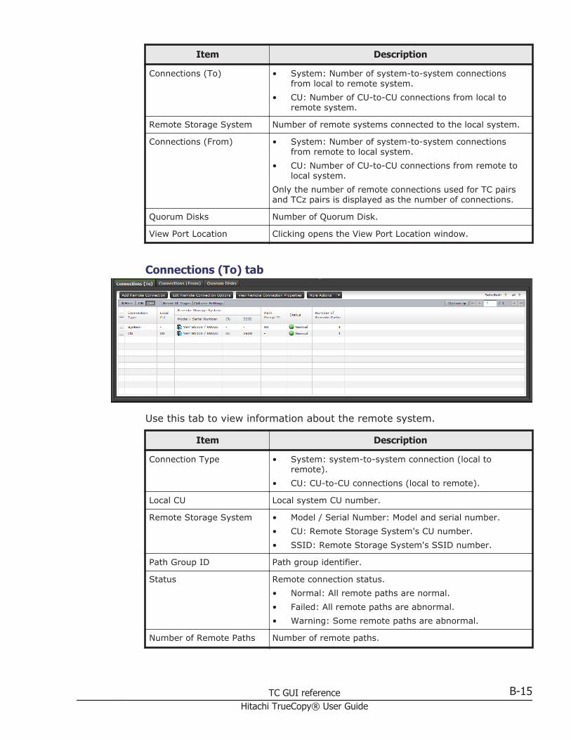
Item Description
Connections (To) • System: Number of system-to-system connectionsfrom local to remote system.
• CU: Number of CU-to-CU connections from local toremote system.
Remote Storage System Number of remote systems connected to the local system.
Connections (From) • System: Number of system-to-system connectionsfrom remote to local system.
• CU: Number of CU-to-CU connections from remote tolocal system.
Only the number of remote connections used for TC pairsand TCz pairs is displayed as the number of connections.
Quorum Disks Number of Quorum Disk.
View Port Location Clicking opens the View Port Location window.
Connections (To) tab
Use this tab to view information about the remote system.
Item Description
Connection Type • System: system-to-system connection (local toremote).
• CU: CU-to-CU connections (local to remote).
Local CU Local system CU number.
Remote Storage System • Model / Serial Number: Model and serial number.• CU: Remote Storage System's CU number.• SSID: Remote Storage System's SSID number.
Path Group ID Path group identifier.
Status Remote connection status.• Normal: All remote paths are normal.• Failed: All remote paths are abnormal.• Warning: Some remote paths are abnormal.
Number of Remote Paths Number of remote paths.
TC GUI reference B-15Hitachi TrueCopy® User Guide

Item Description
Minimum Number of Paths1 The specified minimum number of paths.
RIO MIH Time (sec.)1 The specified RIO MIH time in seconds.
Roundtrip Time (msec.)1 The specified roundtrip time in milliseconds.
FREEZE Option1 The specified the FREEZE option.
Add Remote Connection Clicking opens the Add Remote Connection window.
Edit Remote ConnectionOptions
Clicking opens the Edit Remote Connection Options window.
View Remote ConnectionProperties
Clicking opens the View Remote Connection Propertieswindow.
Add Remote Paths2 Clicking opens the Add Remote Paths window.
Remove Remote Paths2 Clicking opens the Remove Remote Paths window.
Add SSIDs2 Clicking opens the Add SSIDs window.
Delete SSIDs2 Clicking opens the Delete SSIDs window.
Remove RemoteConnection2
Clicking opens the Remove Remote Connection window.
Export2 Clicking opens the window for exporting the tableinformation.
1. This item does not appear in the window by default. To display this item, change theColumn Settings option for the table.
2. Displays when More Actions is clicked.
Connections (From) tab
Use this tab to view information about the remote storage system. Thisinformation is displayed only when remote connections are used for TC andTCz pairs.
Item Description
Connection Type • System: system-to-system connection from remote tolocal.
• CU: CU-to-CU connections from remote to local.
Local CU Local system CU number.
B-16 TC GUI referenceHitachi TrueCopy® User Guide

Item Description
Remote Storage System Displays the following regarding the remote system.• Model / Serial Number: Model and serial number.• CU: CU number.• SSID: SSID number.
Path Group ID Path group identifier.
Export Clicking opens the window for exporting the tableinformation.
Quorum Disks tab
Use this tab to view information about the Quorum Disks allocated to users.
Item Description
Quorum Disk ID Quorum Disk identifier.
Quorum Disk Information about Quorum Disk.• LDEV ID: Volume's virtual LDEV identifier.
LDEV Property window displays by clicking LDEVID.
• LDEV Name: Volume's LDEV Name.• Status: Displays the volume status.
¢ Normal: Volume is in normal status.¢ Blocked: Volume is blocked. Access cannot
be made from the host.¢ Warning: Volume has a problem.¢ Formatting: Volume is being formatted.¢ Preparing Quick Format: Preparation for
quick formatting is in progress.¢ Quick Formatting: Volume is under quick
formatting.¢ Correction Access: Access attribute is being
corrected.¢ Copying: Volume data is being copied.¢ Read Only: Volume is in Read Only status.
Data cannot be written.
TC GUI reference B-17Hitachi TrueCopy® User Guide

Item Description¢ Shredding: Volume is being shredded.¢ - : A blank indicates that the volume is in a
status other than the above.• CLPR: Volume's CLPR.• Capacity: Volume's capacity.
Remote Storage System Model/Serial number of Remote Storage System.
Add Quorum Disks Clicking opens the window for adding Quorum Disks.
Remove Quorum Disks Clicking opens the window for removing QuorumDisks.
Export Clicking opens the window for exporting tableinformation.
Add Remote Connection wizardUse this wizard to set up storage systems for replication.
Add Remote Connection windowUse this window to connect storage systems for remote replication.
For complete information and instructions, see Adding remote connection onpage 5-3.
B-18 TC GUI referenceHitachi TrueCopy® User Guide

In this topic, you can view the following tables.
• Local Storage System on page B-19• Remote Storage System on page B-19• Remote Paths on page B-20• Options on page B-20
Item Description
Connection Type • System: system-to-system connection. TC/UR/URz/GAD.
• CU: CU-to-CU connections. TCz only.
Local Storage System
Item Description
Model Local model.
Serial Number Local serial number.
Local CU TCz only.Local system CU number. Displays when Connection Type isCU.
Remote Storage System
Item Description
Model Remote system's model.
Serial Number Last five or six digits of the remote system serial number,as follows:• VSP G1000: 1 to 99999 (5 digits)• VSP or USP V/VM: 1 to 99999 (5 digits)• HUS VM: 200001 to 265535 (6 digits) (TC/UR only)Note: When using CCI (including Raidcom), the VSP G1000serial number requires a prefix of "3".
Remote CU TCz only.Remote system CU number. Displays when Connection Typeis CU.
SSID TCz only.Remote system SSID.
Add SSIDs TCz only.Clicking adds the SSID to the remote system. Themaximum is four.
TC GUI reference B-19Hitachi TrueCopy® User Guide

Remote Paths
Item Description
Path Group ID TC/UR/URz only.Path group identifier. Displays when Connection Type isSystem.
Minimum Number of Paths Minimum number of remote paths.• TC and TCz: Range is from 1 to 8.• UR and URz: The minimum number is 1, regardless of
the number entered.
Port lists • Left side: local port identifier• Right side: remote port identifier
Add Paths Clicking opens a dialog box for creating additional paths(maximum of eight).
Options
Item Description
RIO MIH Time Time limit between 10 and 100 seconds for the data-transfer operation to complete (15 is the default).
Roundtrip Time (msec.) TC/TCz and GAD only.Time limit between 1 and 500 milliseconds for data copyfrom P-VOL to S-VOL (1 is the default).
FREEZE Option TCz only.Enables or disables support for the CGROUP (FREEZE/RUN)PPRC TSO command.
B-20 TC GUI referenceHitachi TrueCopy® User Guide

Add Remote Connection confirmation window
In this topic, you can view the following tables.
• Selected Remote Connection table on page B-21• Selected Remote Paths table on page B-22
Selected Remote Connection table
Item Description
Connection Type System or CU.
Local CU TCz only.Specified local system CU number. Displays whenConnection Type is CU.
Remote Storage System • Model / Serial Number: Model and serial number.• CU: CU number.• SSID: SSID.
Path Group ID Specified path group identifier.
Number of Remote Paths Specified number of remote paths.
Minimum Number of Paths Specified minimum number of remote paths.
RIO MIH Time (sec.) Specified RIO MIH time.
Roundtrip Time (msec.) Specified roundtrip time.
FREEZE Option Specified FREEZE option.
TC GUI reference B-21Hitachi TrueCopy® User Guide

Selected Remote Paths table
Item Description
Local Port ID Local system port identifier.
Remote Port ID Remote system port identifier.
View Remote Connection Properties windowUse this window to view information about remote connections and paths.
In this topic, you can view the following tables.
• Remote Connection Properties table on page B-23• Remote Paths table on page B-23
B-22 TC GUI referenceHitachi TrueCopy® User Guide

Remote Connection Properties table
Item Description
Connection Type • System: system-to-system connection.• CU: CU-to-CU connections.
Local CU Local system CU number.
Remote Storage System • Model / Serial Number: Model and serial number.• CU: CU number.• SSID: SSID.
Path Group ID Path group identifier.
Channel Type Displays the channel type.• Fibre: Local port type of all remote paths in the remote
connection is Fibre.• FCoE: Local port type of all remote paths in the remote
connection is FCoE.• Mixed: Remote paths with local port types of Fibre and
FCoE both exist in the remote connection.
Status Remote connection status.• Normal: All remote path within remote connection are
fine.• Failed: All remote path within remote connection has
problem.• Warning: Some remote path within remote connection
has problem.
Minimum Number of Paths The specified minimum number of remote paths.
RIO MIH Time The specified RIO MIH time in seconds.
Roundtrip Time The specified roundtrip time in milliseconds.
FREEZE Option Whether the FREEZE option is enabled or disabled.
Registered Time Date and time the connection was established.
Last Update Date Date and time of the last update.
Number of Remote Paths Number of paths specified in the remote connection.
Remote Paths table
Item Description
Local Port ID Remote path's local system port identifier.
Local Port Type Remote path's local port channel type.
Remote Port ID Remote path's remote system port identifier.
Status Remote path status.
TC GUI reference B-23Hitachi TrueCopy® User Guide
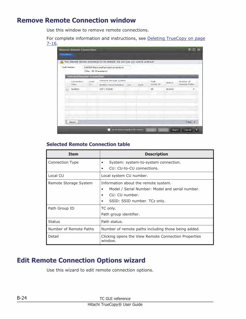
Remove Remote Connection windowUse this window to remove remote connections.
For complete information and instructions, see Deleting TrueCopy on page7-16.
Selected Remote Connection table
Item Description
Connection Type • System: system-to-system connection.• CU: CU-to-CU connections.
Local CU Local system CU number.
Remote Storage System Information about the remote system.• Model / Serial Number: Model and serial number.• CU: CU number.• SSID: SSID number. TCz only.
Path Group ID TC only.Path group identifier.
Status Path status.
Number of Remote Paths Number of remote paths including those being added.
Detail Clicking opens the View Remote Connection Propertieswindow.
Edit Remote Connection Options wizardUse this wizard to edit remote connection options.
B-24 TC GUI referenceHitachi TrueCopy® User Guide

Edit Remote Connection Options windowUse this window to edit remote connection options, such as minimum pathsand round trip time.
For complete information and instructions, see Changing minimum paths,round trip time, other remote connection options on page 7-14.
Selected Remote Connection table
Item Description
Minimum Number of Paths Minimum number of remote paths.• TC and TCz: Range is from 1 to 8.• UR and URz: The minimum number is 1, regardless of
the number entered.
RIO MIH Time Time limit between 10 and 100 seconds for the data-transfer operation to complete (15 is the default).
Roundtrip Time TC/TCz only.Time limit between 1 and 500 milliseconds for data copyfrom P-VOL to S-VOL (1 is the default).
FREEZE Option TCz only.Enables or disables support for the CGROUP (FREEZE/RUN)PPRC TSO command.Displays only when connection type is CU.
TC GUI reference B-25Hitachi TrueCopy® User Guide

Edit Remote Connection confirmation window
Selected Remote Connection table
Item Description
Connection Type • System: system-to-system connection.• CU: CU-to-CU connections.
Local CU Local system CU number.
Remote Storage System Information about the remote system.• Model / Serial Number: Model and serial number.• CU: Remote Storage System's CU number.• SSID: Remote Storage System's SSID number. TCz
only.
Path Group ID Path group identifier.
Number of Remote Paths Number of remote paths including those being added.
Minimum Number of Paths Minimum number of remote paths.• TC and TCz: Range is from 1 to 8.• UR and URz: The minimum number is 1, regardless of
the number entered.
RIO MIH Time Time limit between 10 and 100 seconds for the data-transfer operation to complete (15 is the default).
Roundtrip Time (msec.) TC/TCz only.Time limit between 1 and 500 milliseconds for data copyfrom P-VOL to S-VOL (1 is the default).
FREEZE Option TCz only.Enables or disables support for the CGROUP (FREEZE/RUN)PPRC TSO command.
B-26 TC GUI referenceHitachi TrueCopy® User Guide
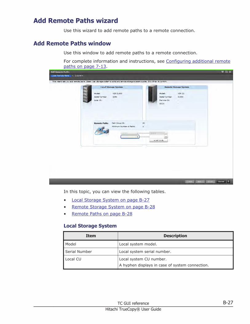
Add Remote Paths wizardUse this wizard to add remote paths to a remote connection.
Add Remote Paths windowUse this window to add remote paths to a remote connection.
For complete information and instructions, see Configuring additional remotepaths on page 7-13.
In this topic, you can view the following tables.
• Local Storage System on page B-27• Remote Storage System on page B-28• Remote Paths on page B-28
Local Storage System
Item Description
Model Local system model.
Serial Number Local system serial number.
Local CU Local system CU number.A hyphen displays in case of system connection.
TC GUI reference B-27Hitachi TrueCopy® User Guide

Remote Storage System
Item Description
Model Remote system model.
Serial Number Remote system serial number.
Remote CU Remote system CU number.A hyphen displays in case of system connection.
SSID Remote system SSID.A hyphen displays in case of system connection.
Remote Paths
Item Description
Path Group ID Path group identifier. A hyphen displays for CU connection.
Minimum Number of Paths Specified minimum number of remote paths.
Port lists • Left side list: local system port identifier.• Right side list: remote system port identifier
Add Paths Clicking adds more paths, up to eight.
Add Remote Paths confirmation window
In this topic, you can view the following tables.
• Selected Remote Connection table on page B-29• Selected Remote Paths table on page B-29
B-28 TC GUI referenceHitachi TrueCopy® User Guide

Selected Remote Connection table
Item Description
Connection Type • System: system-to-system connection.• CU: CU-to-CU connections.
Local CU Local system CU number.
Remote Storage System Information about the remote system.• Model / Serial Number: Model and serial number.• CU: CU number.• SSID: SSID number. TCz only.
Path Group ID TC only.Path group identifier.
Number of Remote Paths Number of remote paths including those being added.
Minimum Number of Paths Specified minimum number of remote paths.
Selected Remote Paths table
Item Description
Local Port ID Local system port identifier.
Remote Port ID Remote system port identifier.
Remove Remote Paths wizardUse this wizard to remove paths from a remote connection.
Remove Remote Paths windowUse this window to remove paths from a remote connection.
For complete information and instructions, see Deleting remote paths on page7-15.
TC GUI reference B-29Hitachi TrueCopy® User Guide

In this topic, you can view the following tables.
• Local Storage System on page B-30• Remote Storage System on page B-30• Remote Paths on page B-31
Local Storage System
Item Description
Model Local system model.
Serial Number Local system serial number.
Local CU Local system CU number.
Remote Storage System
Item Description
Model Remote system model.
Serial Number Remote system serial number.
Remote CU Remote system CU number.
SSID Remote system SSID.
B-30 TC GUI referenceHitachi TrueCopy® User Guide

Remote Paths
Item Description
Path Group ID Path group identifier. A hyphen displays for CU connection.
Minimum Number of Paths Specified minimum number of remote paths.
Port lists • Left side list: local system port identifier.• Right side list: remote system port identifier
Remove Check box for deleting the path from the remoteconnection.
Remove Remote Paths confirmation window
In this topic, you can view the following tables.
• Selected Remote Connection table on page B-31• Selected Remote Paths table on page B-32
Selected Remote Connection table
Item Description
Connection Type • System: system-to-system connection.• CU: CU-to-CU connections.
Local CU Local system CU number.
Remote Storage System Information about the remote system.• Model / Serial Number: Model and serial number.• CU: CU number.
TC GUI reference B-31Hitachi TrueCopy® User Guide

Item Description
• SSID: SSID number. TCz only.
Path Group ID Path group identifier.
Number of Remote Paths Number of remote paths including those being added.
Minimum Number of Paths Specified minimum number of remote paths.
Selected Remote Paths table
Item Description
Local Port ID Local system port identifier.
Remote Port ID Remote system port identifier.
Edit Remote Replica Options wizardUse this wizard to change options that affect the replication system.
Edit Remote Replica Options windowUse this window to change options that affect the replication system.
For complete information and instructions, see Setting number of vols.copied, path blockade, other options on page 5-6.
B-32 TC GUI referenceHitachi TrueCopy® User Guide

In this topic, you can view the following tables.
• Setting Fields on page B-33• Storage System Options on page B-33• CU Options on page B-34
Setting Fields
Item Description
Copy Type Type of pair:• TC: TrueCopy• UR: Universal Replicator• TCMF: TrueCopy for Mainframe• GAD: global-active device• URMF: Universal Replicator for Mainframe
Storage System Options
Following will not be displayed if selecting GAD for Copy Type.
TC GUI reference B-33Hitachi TrueCopy® User Guide

Item Description
Maximum Initial CopyActivities
Number of volumes that can be copied per initial copyoperation.TC/TCMF pair: 1 to 512.UR/URMF pair: 1 to 128
Path Blockade Watch TC/TC only.Number of seconds for the system to monitor blocked paths
Path Blockade SIM Watch TC/TCz only.Number of seconds for the system to monitor SIMs reportedfor blocked paths
Services SIM of RemoteCopy
TC/TCz only.Whether services SIMs in the remote CU are reported to thehost.
CU Options
Following will not be displayed if selecting GAD for Copy Type.
Item Description
Maximum Initial CopyActivities
TC/TCz only.Enables or disables maximum initial copy activities.
CU CU number.
Maximum Initial CopyActivities
TC/TCz only.Maximum initial copy activities. A hyphen displays if Disableis selected in Maximum Initial Copy Activities.
PPRC Support TCz only.Whether PPRC is supported by the host.
Services SIM Whether remote copy service SIMs are reported to the host.
Change CU Options Clicking opens the Change CU Options window.
Maximum Initial CopyActivities
Input Maximum Initial Copy Activities between 1 to 512.Displays only if selecting GAD for Copy Type.
B-34 TC GUI referenceHitachi TrueCopy® User Guide

Change CU Options window
Item Description
Maximum Initial CopyActivities
Number of volumes that can be copied per initial copyoperation.
PPRC support by host TCz only.Whether PPRC is supported by the host.
Services SIM of RemoteCopy
Whether services SIMs in the remote CU are reported to thehost.
TC GUI reference B-35Hitachi TrueCopy® User Guide

Edit Remote Replica Options confirmation window
In this topic, you can view the following tables.
• Storage System Options on page B-36• CU Options on page B-37
Storage System Options
Item Description
Maximum Initial CopyActivities
Number of volumes that can be copied per initial copyoperation.
Path Blockade Watch (sec.) TC/TCz only.Number of seconds for the system to monitor blocked paths
Path Blockade SIM Watch(sec.)
TC/TCz only.Number of seconds for the system to monitor SIMs reportedfor blocked paths
Services SIM TC/TCz only.Whether services SIMs are reported to the host.
B-36 TC GUI referenceHitachi TrueCopy® User Guide

CU Options
Following will not be displayed if selecting GAD for Copy Type.
Item Description
CU CU number.
Maximum Initial CopyActivities
TC/TCz only.Number of volumes that can be copied per initial copyoperation.
PPRC support by host TC/TCz only.Whether PPRC is supported by the host.
Services SIM Whether services SIMs are reported.
Create Pairs wizardUse this wizard to create pairs.
Create TC Pairs window or Create UR Pairs windowUse this window to create pairs.
For complete information and instructions, see Creating pairs on page 6-3.
In this topic, you can view the following tables.
• Settings on page B-38• Primary Volume Selection on page B-38
TC GUI reference B-37Hitachi TrueCopy® User Guide

• Secondary Volume Selection on page B-39• Mirror Selection on page B-39• Options on page B-40• Selected Pairs table on page B-41
Settings
Item Description
Copy Type Type of pair:• TC: TrueCopy• UR: Universal Replicator• TCMF: TrueCopy for Mainframe• URMF: Universal Replicator for Mainframe
Local CU TCz only.Local system's CU number. You can select the CU numberof the local storage system between [00] and [FE].
Remote Storage System Selections in the remote system.• Model / Serial Number: Model and serial number.• Path Group ID: Select the ID of the path group.
Does not display for TCz.• CU/SSID: CU number and SSID. TCz only.
Specify this when you select a provisional CU number inLocal CU.
Primary Volume Selection
Item Description
LU Selection TC and UR only.• Port ID: Local system's port identifier.• Host Group Name: Host group name.
Available LDEVs Information about P-VOLs.• Port ID: Port identifier. TC and UR only.• Host Group Name: Host group name. TC and UR only.• LUN ID: LUN identifier. TC and UR only.• LDEV ID: LDEV identifier.• LDEV Name: LDEV name.• Provisioning Type: Whether the volume is Basic
(internal) or External.• Emulation Type: Emulation type. TC/TCz/URz only.• Capacity: LDEV's capacity.• CLPR: CLPR.• Encryption: Encryption information.
B-38 TC GUI referenceHitachi TrueCopy® User Guide

Item Description
- Enabled: Encryption of the parity group to which theLDEV belongs is enabled.- Disabled: Encryption of the parity group to which theLDEV belongs is disabled.If LDEV is DP-VOL or external volume, a hyphen (-)displays.
Secondary Volume Selection
Item Description
Base Secondary Volume Selections for the initial S-VOL.TC and UR only.• Port ID: Port identifier.• Host Group ID: Host group identifier.• LUN ID: LUN identifier.TCz and URz only.• LDKC: "00" displays, cannot be changed.• CU: For TCz: Volume's CU number.
For URz: the remote system's CU number, ranging from00 to FF.
• LDEV: LDEV number, ranging from 00 to FF.
Selection Type • Interval: Interval for allocating S-VOLs.• Relative Primary Volume: S-VOLs paired with P-VOLs
relative to LUN or LDEV numbers.
Mirror Selection
UR and URz only.
Item Description
Master Journal Master journal number and type.
Mirror ID Mirror's identifier.
Restore Journal Restore journal number.
Current Number of MasterJournal Mirrors
Number of mirrors in the master journal.
Total Number of MasterJournal Mirrors
Displays the following:• Number of mirrors in the master journal.• Number of mirrors added during the Create UR Pairs
operation.• Number of mirrors for the selected volume in Selected
Pairs table.
CTG ID UR only.
TC GUI reference B-39Hitachi TrueCopy® User Guide

Item Description
Displays consistency groups registered in the storagesystem. An asterisk indicates it is assigned to a pair in theSelect Pairs table.
Options
Item Description
Primary Volume FenceLevel
TC and TCz onlyWhether the P-VOL can be written to when the pair is splitdue to error.• Data: Cannot be written to.• Status: Can be written to only if the primary system
can change S-VOL status to PSUE; otherwise no.• Never: Can be written to.
Initial Copy Type Whether data is copied to the S-VOL during this operation.• Entire Volume: Data is copied. The default.• None: Data is not copied.• Delta: Data is not copied. UR and URz only.
Copy Pace TC and TCz onlyNumber of tracks to be copied per remote I/O during theoperation.• For TC, the range is 1-15.• TCz options are 3 and 15.
Initial Copy Priority Scheduling order for the initial copy operation. Range is 1 to256; default is 32.
CFW Data TCz only.Whether CFW (DASD fast write) data is copied to the S-VOL.• Primary Volume Only: Data is not copied to S-VOL
(default).• Secondary Volume Copy: Data is copied to S-VOL.
DFW to Secondary Volume TCz only.Whether the primary system splits the pair when thesecondary system cannot copy DFW data to the S-VOL• Require: Splits the pair.• Not Require: Does not split.
Host I/O Time StampTransfer
TCz only.Whether the host I/O time stamp is transferred from P-VOLto S-VOL.
Error Level UR and URz only.Whether to split all pairs in the mirror if a failure occursduring this operation:• Mirror: Pairs in the mirror are split.
B-40 TC GUI referenceHitachi TrueCopy® User Guide

Item Description
• LU (UR) or Volume (URz): Only the failed pair is split.
CFW URz only.Whether to copy cache fast write (CFW) data to the S-VOL.• Primary Volume Only: Does not copy. Default.• Secondary Volume Copy: Copies.
Selected Pairs table
Item Description
Local Storage System Information about volumes in the accessed system.• LDEV ID: LDEV identifier.• LDEV Name: LDEV name.• Port ID: Port identifier. TC/UR only.• Host Group Name: Host group name. TC/UR only.• LUN ID: LUN identifier. TC/UR only.• Emulation Type: Volume's emulation type.
TCz/TC/URz only.• Journal ID: Journal's identifier. UR/URz only.• Mirror ID: Mirror identifier. UR/URz only.• Capacity: Volume's capacity.• CLPR: Volume's CLPR.• Encryption: Encryption information
- Enabled: Encryption of the parity group to which theLDEV belongs is enabled.- Disabled: Encryption of the parity group to which theLDEV belongs is disabled.If LDEV is DP-VOL or external volume, a hyphen (-)displays.
Remote Storage System Information about the remote system.• Model / Serial Number: Model and serial number.• SSID: SSID number. TCz only.• LDEV ID: LDEV identifier. TCz/URz only• Port ID: Port identifier. TC/UR only.• Host Group Name: Host group name. TC/UR only.• LUN ID: LUN identifier. TC/UR only.• Journal ID: Journal's identifier. UR/URz only.
Path Group ID Path group ID. Not used with TCz.
Fence Level TC and TCz only.P-VOL fence level.
CTG ID UR only.Consistency group identifier.
TC GUI reference B-41Hitachi TrueCopy® User Guide

Item Description
Initial Copy Type Type of the pair create operation.
Copy Pace TC and TCz only.Number of tracks copied per remote I/O operation.
Initial Copy Priority Scheduling order for pair create operation.
CFW Data TCz only.Whether CFW data is copied to the S-VOL.
DFW to Secondary Volume TCz only.Whether the primary system splits pairs when thesecondary system cannot copy DFW data to the S-VOL.
Host I/O Time StampTransfer
TCz only.Whether the host's time stamp is transferred to the S-VOL.
Error Level UR and URz only.Whether all pairs in the mirror are split if a failure occursduring this operation.
CFW URz only.Whether CFW data is copied to the S-VOL.
Change Settings Clicking opens the Change Settings window.
Delete Deletes the specified pair from the table.
Change Settings windowUse this window in the pair creation wizard to change options that affect howthe pair is created.
B-42 TC GUI referenceHitachi TrueCopy® User Guide

Item Description
Base Secondary Volume Selections for the initial S-VOL.TC, UR and GAD only.• Port ID: Port identifier.• Host Group ID: Host group identifier.• LUN ID: LUN identifier.TCz and URz only.• LDKC: "00" displays, cannot be changed.• CU: For TCz: the volume's CU number.
For URz: the remote system's CU number, ranging from00 to FF.
• LDEV: LDEV number, ranging from 00 to FF.• Interval: The interval for allocating S-VOLs to P-VOLs.
Primary Volume FenceLevel
TC and TCz onlyWhether the P-VOL can be written to when the pair is splitdue to error.• Data: The P-VOL cannot be written to.• Status: The P-VOL can be written to only if the primary
system can change S-VOL status to PSUE (TrueCopy)or Suspend (TrueCopy for Mainframe); otherwise no.
• Never: The P-VOL can be written to.
Initial Copy Type Whether data is copied to the S-VOL when the pair iscreated.
TC GUI reference B-43Hitachi TrueCopy® User Guide
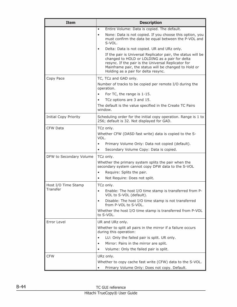
Item Description
• Entire Volume: Data is copied. The default.• None: Data is not copied. If you choose this option, you
must confirm the data be equal between the P-VOL andS-VOL.
• Delta: Data is not copied. UR and URz only.If the pair is Universal Replicator pair, the status will bechanged to HOLD or LOLDING as a pair for deltaresync. If the pair is the Universal Replicator forMainframe pair, the status will be changed to Hold orHolding as a pair for delta resync.
Copy Pace TC, TCz and GAD only.Number of tracks to be copied per remote I/O during theoperation.• For TC, the range is 1-15.• TCz options are 3 and 15.The default is the value specified in the Create TC Pairswindow.
Initial Copy Priority Scheduling order for the initial copy operation. Range is 1 to256; default is 32. Not displayed for GAD.
CFW Data TCz only.Whether CFW (DASD fast write) data is copied to the S-VOL.• Primary Volume Only: Data not copied (default).• Secondary Volume Copy: Data is copied.
DFW to Secondary Volume TCz only.Whether the primary system splits the pair when thesecondary system cannot copy DFW data to the S-VOL• Require: Splits the pair.• Not Require: Does not split.
Host I/O Time StampTransfer
TCz only.• Enable: The host I/O time stamp is transferred from P-
VOL to S-VOL (default).• Disable: The host I/O time stamp is not transferred
from P-VOL to S-VOL.Whether the host I/O time stamp is transferred from P-VOLto S-VOL.
Error Level UR and URz only.Whether to split all pairs in the mirror if a failure occursduring this operation:• LU: Only the failed pair is split. UR only.• Mirror: Pairs in the mirror are split.• Volume: Only the failed pair is split.
CFW URz only.Whether to copy cache fast write (CFW) data to the S-VOL.• Primary Volume Only: Does not copy. Default.
B-44 TC GUI referenceHitachi TrueCopy® User Guide

Item Description
• Secondary Volume Copy: Copies.
Create Pairs confirmation window
Selected Pairs table
Item Description
Local Storage System Information about volumes in the accessed system.• LDEV ID: LDEV identifier.• LDEV Name: LDEV name.• Port ID: Port identifier. TC/UR only.• Host Group Name: Host group name. TC/UR only.• LUN ID: LUN identifier. TC/UR only.• Emulation Type: Volume's emulation type.
TCz/TC/URz only.• Journal ID: Journal's identifier. UR/URz only.• Mirror ID: Mirror identifier. UR/URz only.• Capacity: Volume's capacity.• CLPR: Volume's CLPR.• Encryption: Encryption information
- Enabled: Encryption of the parity group to which theLDEV belongs is enabled.
TC GUI reference B-45Hitachi TrueCopy® User Guide

Item Description
- Disabled: Encryption of the parity group to which theLDEV belongs is disabled.If LDEV is DP-VOL or external volume, a hyphen (-)displays.
Copy Type Type of pair:• TC: TrueCopy• UR: Universal Replicator• TCMF: TrueCopy for Mainframe• URMF: Universal Replicator for Mainframe
Remote Storage System Information about volumes in the system connected to thesystem you accessed.• Model / Serial Number: Model and serial number.• SSID: SSID number. TCz only.• LDEV ID: LDEV identifier. TCz/URz only.• Port ID: Port identifier. TC/UR only.• Host Group Name: Host group name. TC/UR only.• LUN ID: LUN identifier. TC/UR only.• Journal ID: Journal's identifier. UR/URz only.
Path Group ID Path group identifier. Not shown for TCz.
CTG ID UR only.Consistency group identifier.
Fence Level TC and TCz onlyWhether the P-VOL can be written to when the pair is splitdue to error.• Data: Cannot be written to.• Status: Can be written to only if the primary system
can change S-VOL status to PSUE; otherwise no.• Never: Can be written to.
Initial Copy Type Whether data is copied to the S-VOL during this operation.• Entire Volume: Data is copied. The default.• None: Data is not copied.• Delta: Data is not copied. UR and URz only.
Copy Pace TC and TCz onlyNumber of tracks to be copied per remote I/O during theoperation.• For TC, the range is 1-15.• TCz options are 3 and 15.
Initial Copy Priority Scheduling order for the initial copy operation. Range is 1 to256; default is 32.
CFW Data TCz only.Whether CFW (DASD fast write) data is copied to the S-VOL.
B-46 TC GUI referenceHitachi TrueCopy® User Guide

Item Description
• Primary Volume Only: Data not copied (default).• Secondary Volume Copy: Data is copied.This is displayed only for TCz pairs.
DFW to Secondary Volume TCz only.Whether the primary system splits the pair when thesecondary system cannot copy DFW data to the S-VOL• Require: Splits the pair.• Not Require: Does not split.
Host I/O Time StampTransfer
TCz only.Whether the host I/O time stamp is transferred from P-VOLto S-VOL.
Error Level UR and URz only.Whether to split all pairs in the mirror if a failure occursduring this operation:• Mirror: Pairs in the mirror are split.• Volume: Only the failed pair is split.
CFW URz only.Whether to copy cache fast write (CFW) data to the S-VOL.• Primary Volume Only: Does not copy. Default.• Secondary Volume Copy: Copies.
Split Pairs wizardUse this wizard to split pairs.
Split Pairs windowUse this window to split pairs.
For complete information and instructions, see Splitting pairs on page 6-6.
TC GUI reference B-47Hitachi TrueCopy® User Guide

In this topic, you can view the following tables.
• Selected Pairs table on page B-48• Setting Fields on page B-49
Selected Pairs table
Item Description
Local Storage System Information about volumes in the accessed system.• LDEV ID: LDEV identifier.• LDEV Name: LDEV name.• Pair Position: Whether volume is a P-VOL or S-VOL.• Emulation Type: Volume's emulation type.• Capacity: Volume's capacity.• CLPR: Volume's CLPR.
Copy Type Type of pair:• TC: TrueCopy• TCMF: TrueCopy for Mainframe
Status Pair status.
Remote Storage System Information about the remote system.• Model / Serial Number: Model and serial number.• SSID: SSID number. TCz only.• LDEV ID: LDEV identifier.
Path Group ID TC only.
B-48 TC GUI referenceHitachi TrueCopy® User Guide

Item Description
Path group identifier.
CTG ID Pair's consistency group identifier.
CTG Utilization Whether the consistency group is shared by multiplestorage systems.• Single: The consistency group consists of a single pair
of primary and secondary storage systems.• Multi: The consistency group consists: The consistency
group consists of multiple storage systems.
Preserve Mirror Status • Blank: Indicates that it is a Preserve Mirror statuswithout any problem or it is not a Preserve Mirror pair.
• Withdrawn: Indicates that pair volume data does notmatch due to suspending copy of CompatibleFlashCopy® V2.
Fence Level P-VOL fence level.
Setting Fields
Item Description
Secondary Volume Write TC only.Whether the S-VOL can be written to while the pair is split.• Enable: Can write to S-VOL. Available only when
performing the split operation from the pair's primarystorage system.
• Disable: Prevents writing to S-VOL. Default.
Primary Volume Write Whether the P-VOL can be written to while the pair is split.• Depend on Primary Volume Fence Level: Writing to P-
VOL depends on the Primary Volume Fence LevelSetting. Default.
• Disable: Prevents writing to the P-VOL. Available onlywhen performing the split operation from the pair'sprimary storage system.
SSB Transfer (F/M=FB) TCz only.Whether to report SSB (sense byte) to the host. Enable/Disable (the default). Enable is available only whenperforming the split operation from the pair's primarystorage system.
TC GUI reference B-49Hitachi TrueCopy® User Guide

Split Pairs confirmation window
Selected Pairs table
Item Description
Local Storage System Information about volumes in the accessed system.• LDEV ID: LDEV identifier.• LDEV Name: LDEV name.• Pair Position: Whether volume is a P-VOL or S-VOL.• Emulation Type: Volume's emulation type.• Capacity: Volume's capacity.• CLPR: Volume's CLPR.
Copy Type Type of pair:• TC: TrueCopy• TCMF: TrueCopy for Mainframe
Status Pair status.
Secondary Volume Write TC only.Whether the S-VOL can be written to while the pair is split.• Enable: Can write to S-VOL.• Disable: Prevents writing to S-VOL. Default.A hyphen displays if performing the split operation from thepair's secondary storage system, regardless of the selectedoption.
Primary Volume Write Whether the P-VOL can be written to while the pair is split.
B-50 TC GUI referenceHitachi TrueCopy® User Guide

Item Description
• Depend on Primary Volume Fence Level: Writing to P-VOL depends on the Primary Volume Fence LevelSetting. Default.
• Disable: Prevents writing to the P-VOL.A hyphen displays if performing the split operation from thepair's secondary storage system, regardless of the selectedoption.
Fence Level P-VOL's fence level setting.
SSB Transfer (F/M=FB) TCz only.Whether to report SSB (sense byte) to the host. Enable/Disable.A hyphen displays if performing the split operation from thepair's secondary storage system, regardless of the selectedoption.
Remote Storage System Information about the remote system.• Model / Serial Number: Model and serial number.• SSID: SSID number. TCz only.• LDEV ID: LDEV identifier.
Path Group ID TC only.Path group identifier.
CTG ID Pair's consistency group identifier.
CTG Utilization Whether the consistency group is shared by multiplestorage systems.• Single: The consistency group consists of a single pair
of primary and secondary storage systems.• Multi: The consistency group consists of multiple
storage systems.
Preserve Mirror Status • Blank: Indicates that it is a Preserve Mirror statuswithout any problem or it is not a Preserve Mirror pair.
• Withdrawn: Indicates that pair volume data does notmatch due to suspending copy of CompatibleFlashCopy® V2.
Resync Pairs wizardUse this wizard to resynchronize pairs.
Resync Pairs windowUse this window to resynchronize pairs.
For complete information and instructions, see Resynchronizing pairs on page6-8.
TC GUI reference B-51Hitachi TrueCopy® User Guide

In this topic, you can view the following tables.
• Selected Pairs table on page B-52• Setting Fields on page B-53
Selected Pairs table
Item Description
Local Storage System Information about volumes in the accessed system.• LDEV ID: LDEV identifier.• LDEV Name: LDEV name.• Emulation Type: Volume's emulation type.• Capacity: Volume's capacity.• CLPR: Volume's CLPR.
Copy Type Type of pair:• TC: TrueCopy• TCMF: TrueCopy for Mainframe
Status Pair status.
Copy Priority Order that pairs are resynchronized.
Remote Storage System Information about the remote system.• Model / Serial Number: Model and serial number.• SSID: SSID number. TCz only.• LDEV ID: LDEV identifier.
Path Group ID TC only.Path group identifier.
CTG ID Pair's consistency group identifier.
B-52 TC GUI referenceHitachi TrueCopy® User Guide

Item Description
CTG Utilization Whether the consistency group is shared by multiplestorage systems.• Single: The consistency group consists of a single pair
of primary and secondary storage systems.• Multi: The consistency group consists of multiple
storage systems.
Preserve Mirror Status • Blank: Indicates that it is a Preserve Mirror statuswithout any problem or it is not a Preserve Mirror pair.
• Withdrawn: Indicates that pair volume data does notmatch due to suspending copy of CompatibleFlashCopy® V2.
Copy Priority Order that pairs are resynchronized.
Setting Fields
Item Description
Primary Volume FenceLevel
Whether the P-VOL can be written to when the pair is splitdue to error.• Data: The P-VOL cannot be written to.• Status: The P-VOL can be written to only if the primary
system can change S-VOL status to PSUE (TrueCopy)or Suspend (TrueCopy for Mainframe); otherwise no.
• Never: The P-VOL can be written to.
Copy Pace Number of tracks to be copied per remote I/O during theoperation.• For TC, the range is 1-15.• TCz options are 3 and 15.
Host I/O Time StampTransfer
TCz only.• Enable: The host I/O time stamp is transferred from P-
VOL to S-VOL.• Disable: The host I/O time stamp is transferred from P-
VOL to S-VOL.Whether the host I/O time stamp is transferred from P-VOLto S-VOL.
TC GUI reference B-53Hitachi TrueCopy® User Guide

Resync Pairs confirmation window
Selected Pairs table
Item Description
Local Storage System Information about volumes in the accessed system.• LDEV ID: LDEV identifier.• LDEV Name: LDEV name.• Pair Position: Whether volume is a P-VOL or S-VOL.• Emulation Type: Volume's emulation type.• Capacity: Volume's capacity.• CLPR: Volume's CLPR.
Copy Type Type of pair:• TC: TrueCopy• TCMF: TrueCopy for Mainframe
Status Pair status.
Fence Level Whether the P-VOL can be written to when the pair is splitdue to error.• Data: Cannot be written to.• Status: Can be written to only if the primary system
can change S-VOL status to PSUE; otherwise no.• Never: Can be written to.
Copy Pace Number of tracks to be copied per remote I/O during theoperation.• For TC, the range is 1-15.• TCz options are 3 and 15.
Copy Priority Order that pairs are resynchronized.
B-54 TC GUI referenceHitachi TrueCopy® User Guide

Item Description
Host I/O Time StampTransfer
TCz only.Whether the host I/O time stamp is transferred from P-VOLto S-VOL.
Remote Storage System Information about the remote system.• Model / Serial Number: Model and serial number.• SSID: SSID number. TCz only.• LDEV ID: LDEV identifier.
Path Group ID TC only.Path group identifier.
CTG ID Pair's consistency group identifier.
CTG Utilization Whether the consistency group is shared by multiplestorage systems.• Single: The consistency group consists of a single pair
of primary and secondary storage systems.• Multi: The consistency group consists of multiple
storage systems.
Preserve Mirror Status • Blank: Indicates that it is a Preserve Mirror statuswithout any problem or it is not a Preserve Mirror pair.
• Withdrawn: Indicates that pair volume data does notmatch due to suspending copy of CompatibleFlashCopy® V2.
Delete Pairs wizardUse this wizard to delete pairs.
Delete Pairs windowUse this window to delete pairs.
For complete information and instructions, see Deleting pairs on page 6-9.
TC GUI reference B-55Hitachi TrueCopy® User Guide

In this topic, you can view the following tables.
• Selected Pairs table on page B-56• Settings on page B-57
Selected Pairs table
Item Description
Local Storage System Information about volumes in the accessed system.• LDEV ID: LDEV identifier.• LDEV Name: LDEV name.• Pair Position: Whether volume is a P-VOL or S-VOL.• Emulation Type: Volume's emulation type.• Capacity: Volume's capacity.• CLPR: Volume's CLPR.
Copy Type Type of pair:• TC: TrueCopy• TCMF: TrueCopy for Mainframe
Status Pair status.
Remote Storage System Information about the remote system.• Model / Serial Number: Model and serial number.• SSID: SSID number. TCz only.• LDEV ID: LDEV identifier.
Path Group ID TC only.
B-56 TC GUI referenceHitachi TrueCopy® User Guide

Item Description
Path group identifier.
CTG ID Pair's consistency group identifier.
CTG Utilization Whether the consistency group is shared by multiplestorage systems.• Single: The consistency group consists of a single pair
of primary and secondary storage systems.• Multi: The consistency group consists of multiple
storage systems.
Preserve Mirror Status • Blank: Indicates that it is a Preserve Mirror statuswithout any problem or it is not a Preserve Mirror pair.
• Withdrawn: Indicates that pair volume data does notmatch due to suspending copy of CompatibleFlashCopy® V2.
Fence Level Whether the P-VOL can be written to when the pair is splitdue to error.• Data: The P-VOL cannot be written to.• Status: The P-VOL can be written to only if the primary
system can change S-VOL status to PSUE (TrueCopy)or Suspend (TrueCopy for Mainframe); otherwise no.
• Never: The P-VOL can be written to.
Settings
Item Description
Delete Mode How the pair is deleted.• Normal: Deletes the pair if the primary system can
change both P-VOL and S-VOL to unpaired volumes.Default.
• Force: Deletes the pair even when the primary systemcannot communicate with the secondary system.
• Force (All pairs in the same remote connections):Deletes forcibly all pairs using the same remoteconnection. TCz only.
TC GUI reference B-57Hitachi TrueCopy® User Guide

Delete Pairs confirmation window
Selected Pairs table
Item Description
Local Storage System Information about volumes in the accessed system.• LDEV ID: LDEV identifier.• LDEV Name: LDEV name.• Pair Position: Whether volume is a P-VOL or S-VOL.• Emulation Type: Volume's emulation type.• Capacity: Volume's capacity.• CLPR: Volume's CLPR.
Copy Type Type of pair:• TC: TrueCopy• TCMF: TrueCopy for Mainframe
Status Pair status.
Delete Mode How the pair is deleted.
Remote Storage System Information about the remote system.• Model / Serial Number: Model and serial number.• SSID: SSID number. TCz only.• LDEV ID: LDEV identifier.
Path Group ID TC only.Path group identifier.
CTG ID Pair's consistency group identifier.
CTG Utilization Whether the consistency group is shared by multiplestorage systems.• Single: The consistency group consists of a single pair
of primary and secondary storage systems.
B-58 TC GUI referenceHitachi TrueCopy® User Guide

Item Description
• Multi: The consistency group consists of multiplestorage systems.
Preserve Mirror Status • Blank: Indicates that it is a Preserve Mirror statuswithout any problem or it is not a Preserve Mirror pair.
• Withdrawn: Indicates that pair volume data does notmatch due to suspending copy of CompatibleFlashCopy® V2.
Fence Level P-VOL fence level.
Force Delete Pairs (TC Pairs) windowUse this window to forcibly delete pairs.
For complete information and instructions, see Forcibly deleting pairs on page7-9.
Selected LDEVs table
Item Description
LDEV ID LDEV identifier.
LDEV Name LDEV name.
Emulation Type Emulation type.
Capacity Capacity.
CLPR CLPR number.
TC GUI reference B-59Hitachi TrueCopy® User Guide

Edit Pair Options wizardUse this wizard to change pair options.
Edit Pair Options windowUse this window to change pair options.
For complete information and instructions, see Changing P-VOL Fence Levelon page 7-8.
Item Description
Primary Volume FenceLevel
Whether the P-VOL can be written to when the pair is splitdue to error.• Data: The P-VOL cannot be written to.• Status: The P-VOL can be written to only if the primary
system can change S-VOL status to PSUE (TrueCopy)or Suspend (TrueCopy for Mainframe); otherwise no.
• Never: The P-VOL can be written to.The value set for the selected pair is the default.
CFW Data TCz only.Whether CFW (DASD fast write) data is copied to the S-VOL.• Primary Volume Only: Data not copied (default).• Secondary Volume Copy: Data is copied.The value set for the selected pair is the default.
B-60 TC GUI referenceHitachi TrueCopy® User Guide
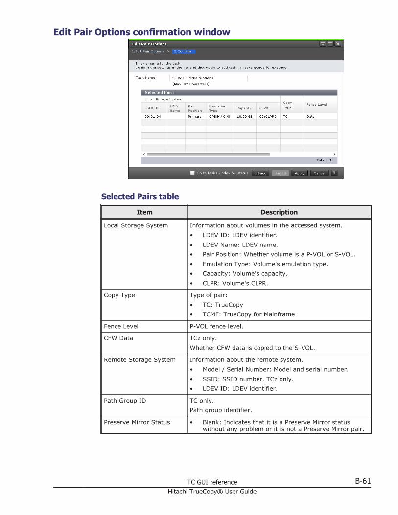
Edit Pair Options confirmation window
Selected Pairs table
Item Description
Local Storage System Information about volumes in the accessed system.• LDEV ID: LDEV identifier.• LDEV Name: LDEV name.• Pair Position: Whether volume is a P-VOL or S-VOL.• Emulation Type: Volume's emulation type.• Capacity: Volume's capacity.• CLPR: Volume's CLPR.
Copy Type Type of pair:• TC: TrueCopy• TCMF: TrueCopy for Mainframe
Fence Level P-VOL fence level.
CFW Data TCz only.Whether CFW data is copied to the S-VOL.
Remote Storage System Information about the remote system.• Model / Serial Number: Model and serial number.• SSID: SSID number. TCz only.• LDEV ID: LDEV identifier.
Path Group ID TC only.Path group identifier.
Preserve Mirror Status • Blank: Indicates that it is a Preserve Mirror statuswithout any problem or it is not a Preserve Mirror pair.
TC GUI reference B-61Hitachi TrueCopy® User Guide

Item Description
• Withdrawn: Indicates that pair volume data does notmatch due to suspending copy of CompatibleFlashCopy® V2.
View Pair Properties (Remote) windowUse this window to view the data related to pairs and their volumes.
For complete information and instructions, see Monitoring pair status, licensecapacity on page 7-2.
In this topic, you can view the following tables.
• Pair Properties on page B-63• Pair Detail on page B-63
B-62 TC GUI referenceHitachi TrueCopy® User Guide

Pair Properties
Item Description
Local StorageSystem box
Displays the following information about the local system.• LDEV ID (LDEV name): P-VOL's LDEV identifier and name, which
displays when you hover the mouse over it.• Number of Paths: Number of data paths between primary and
secondary systems.• Provisioning Type, Encrypted: Local system's volume type and
encryption status.Encryption status is displayed only when the provisioning type isBasic and the volume's encryption is Enabled.
• Emulation Type, Capacity: Local system's emulation type andcapacity.
• Model/Serial number, CLPR: Local system's model, serial number,and CLPR.
Copy Type,Status
Pair's copy type and pair status.
Path Group Pair's path group.If the P-VOL is in the primary storage system, clicking the path groupID (TC) or Remote Paths (TCz) displays the remote path list.
RemoteStorageSystem box
Displays the following information about the remote system.• LDEV ID: S-VOL's LDEV identifier and name, which displays when
you hover the mouse over it.• Port ID/Host Group ID/LUN ID: Port, host group, and LUN
identifiers. Information is useful when specifying an LDEV ID at paircreation. It does not change, even if path settings are changed. TConly.
• Emulation type, Capacity: Remote system's volume emulation typeand capacity.
• Model/Serial number: Remote system's model, serial number.For CU-by-CU connection, SSID is also displayed.
Pair Detail
Item Description
Status Pair's status
Update Type One of the following:• Sync: It is a TC or TCz pair which is not assigned to consistency
group.• Sync (Specified CTG): It is a TC or TCz pair created by specifying
consistency group.
CTG ID Consistency group identifier
CTG Utilization Whether the consistency group is shared by multiple storage systems.• Single: The consistency group consists of a single pair of primary
and secondary storage systems.
TC GUI reference B-63Hitachi TrueCopy® User Guide

Item Description
• Multi: The consistency group consists of multiple storage systems.
Preserve MirrorStatus
TCz only.Preserve Mirror Status.
Fence Level Whether the P-VOL can be written to when the pair is split due to error.• Data: The P-VOL cannot be written to.• Status: The P-VOL cannot be written to only if the primary system
cannot change S-VOL status to PSUE (TrueCopy) or Suspend(TrueCopy for Mainframe); otherwise no.
• Never: The P-VOL can be written to.
Host I/O TimeStamp Transfer
TCz only.Specified time stamp transfer value.
SecondaryVolume Written
Whether data can be written (Enabled) or not written (Disabled) to theS-VOL. The pair must be split for Enabled to display.If the volume accessed is an S-VOL and can be written to, Enabled/Received or Enabled/Not Received displays. Indicates whether a writeoperation is received from the host or not.
Copy Pace Speed that data is copied.
Initial CopyPriority
Scheduling order for the initial copy operation.Range is 1 to 256 for TC; 0 to 256 for TCz; default is 32.
Paired Time Date and time pair-creation was completed.
Last UpdateTime
Date and time that the last update was run.
Pair Copy Time Elapsed time for paircreate or pairresync operation.
CFW Data TCz only.Whether CFW data is copied to the S-VOL as specified during paircreation.
DFW toSecondaryVolume
TCz only.Whether the primary system splits the pair when the secondary systemcannot copy DFW data to the S-VOL.
Local StorageSystem
• Virtual storage machine: Virtual storage machine's model type andserial number.
• Virtual LDEV ID: Volume's virtual LDEV identifier.• Virtual Device Name: Volume's virtual device name, in the format:
virtual emulation type/number of virtual LUSE volumes/virtual CVSattribute- Only attributes that are specified display.- "CVS" displays at the end of the device name, if the virtual CVSattribute is specified.- A blank indicates no values are specified.
• Virtual SSID: Volume's virtual SSID. A blank indicates that novirtual SSID is specified.
B-64 TC GUI referenceHitachi TrueCopy® User Guide

Item Description
RemoteStorageSystem
• Virtual storage machine: Virtual storage machine's model type andserial number.
• Virtual LDEV ID: Volume's virtual LDEV identifier.
View Pair Synchronous Rate windowUse this window to view the percentage of synchronized data between P-VOLand S-VOL.
For complete information and instructions, see Monitoring TC pairsynchronous rate on page 7-6.
Pairs table
Item Description
Local Storage System Information about volumes in the local storage system.• LDEV ID: LDEV identifier. Clicking the link opens the
LDEV Properties window.• LDEV Name: LDEV name.• Pair Position: Whether the volume is a primary or
secondary volume.• CLPR: Volume's CLPR.• Virtual storage machine: Virtual storage machine's
model type and serial number.• Virtual LDEV ID: Volume's virtual LDEV identifier.• Virtual Device Name: Volume's virtual device name, in
the format:virtual emulation type/number of virtual LUSE volumes/virtual CVS attribute- Only attributes that are specified display.- "CVS" displays at the end of the device name, if thevirtual CVS attribute is specified.- A blank indicates no values are specified.
TC GUI reference B-65Hitachi TrueCopy® User Guide

Item Description
• Virtual SSID: Volume's virtual SSID. A blank indicatesthat no virtual SSID is specified.
Copy Type TC Pairs tab:• TC: TrueCopy• TCMF: TrueCopy for Mainframe
Status Pair status.For status definitions, see Pair status definitions on page7-3
Synchronous Rate (%) Displays the concordance rate between the volume in theprimary storage system and the volume in the remotesystem. "(queuing)" displays if processing has not started.
Remote Storage System Information about volumes in the system connected to thesystem you accessed.• Model / Serial Number: Remote system's model and
serial number.• SSID: Remote system's SSID number. TCz only.• LDEV ID: LDEV identifier.• Virtual storage machine: Virtual storage machine's
model type and serial number.• Virtual LDEV ID: Volume's virtual LDEV identifier.
Path Group ID Path group identifier. TC only.
Refresh Updates the information.
Histories windowUse this window to review the operations that have been performed on a pair.
For complete information and instructions, see Monitoring TC operationshistory on page 7-7.
B-66 TC GUI referenceHitachi TrueCopy® User Guide

In this topic, you can view the following tables.
• Settings on page B-67• Histories table on page B-67
Settings
Item Description
Copy Type Type of pair:• TC: TrueCopy• UR: Universal Replicator• TCMF: TrueCopy for Mainframe• URMF: Universal Replicator for Mainframe• GAD: global-active device
Last Updated Date and time of the last update. Displays after Copy Typeis specified.
Page Number Page number. Click the button, turn over the page. Displaysafter Copy Type is specified.
Histories table
Item Description
Date and Time Date and time of the operation.
Local Storage System Information about volumes in the accessed system.• LDEV ID: LDEV identifier.
TC GUI reference B-67Hitachi TrueCopy® User Guide

Item Description
• Provisioning Type: Whether the volume is Basic(internal) or External.
• Pair Position: Whether the volume is a primary orsecondary volume. GAD only.
• Journal ID: Journal's identifier. UR/URz only.• Mirror ID: Mirror's identifier. UR/URz only.
Remote Storage System Information about volumes in the system connected to thesystem you accessed.• LDEV ID: LDEV identifier.• Model / Serial Number: Remote Storage System's
model and serial number. GAD only.• Provisioning Type: Whether the volume is Basic
(internal) or External.
EXCTG ID EXCTG identifier.URz only.
Mirror ID Mirror identifier. GAD only.
Quorum Disk ID Quorum Disk identifier. GAD only.
Virtual Storage Machine Information about volumes in the Virtual Storage Machine.GAD only.• Model / Serial Number: Virtual Storage System's model
and serial number.• LDEV ID: Volume's LDEV identifier.
Description Code Description Code. GAD only.
Description Describes the operation.
Copy Time Elapsed time for create or resync pairs operation. When theDescription is other than Pair Add Complete or Pair Resync.Complete, a hyphen displays.
Started Start time of create or resync pairs operation. When theDescription is other than Pair Add Complete or Pair Resync.Complete, a hyphen displays.
Export Clicking opens the window for exporting table information.
B-68 TC GUI referenceHitachi TrueCopy® User Guide

Glossary
This glossary defines the special terms used in this document. Click the letter links below tonavigate.
#
2DCtwo-data-center. Refers to the primary and secondary sites, or data centers, in whichTrueCopy (TC) and Universal Replicator (UR) combine to form a remote replicationconfiguration.In a 2DC configuration, data is copied from a TC primary volume at the primary site tothe UR master journal volume at an intermediate site, then replicated to the URsecondary volume at the secondary site. Since this configuration side-steps the TCsecondary volume at the intermediate site, the intermediate site is not considered adata center.
3DCthree-data-center. Refers to the primary, intermediate, and secondary sites, or datacenters, in which TC and UR combine to form a remote replication configuration. A 3DCconfiguration can also combine three UR sites.In a 3DC configuration, data is copied from a primary site to an intermediate site andthen to a secondary site (3DC cascade configuration), or from a primary site to twosecondary sites (3DC multi-target configuration).
A
alternate pathA secondary path (port, target ID, LUN) to a logical volume, in addition to the primarypath, that is used as a backup in case the primary path fails.
# A B C D E F G H I J K L M N O P Q R S T U V W X Y Z
Glossary-1Hitachi TrueCopy® User Guide

arrayAnother name for a RAID storage system.
array groupSee RAID group.
asyncasynchronous
ATTIME suspendA consistency group task in which multiple pairsplit operations are performedsimultaneously at a pre-determined time using BCM or CCI.
audit logFiles that store a history of the operations performed from Device Manager - StorageNavigator and the service processor (SVP), commands that the storage system receivedfrom hosts.
B
base emulation typeEmulation type that is set when drives are installed. Determines the device emulationtypes that can be set in the RAID group.
BCbusiness continuity
BCMBusiness Continuity Manager
bladeA computer module, generally a single circuit board, used mostly in servers.
BLK, blkblock
bmpbitmap
C
C/TSee consistency time (C/T).
# A B C D E F G H I J K L M N O P Q R S T U V W X Y Z
Glossary-2Hitachi TrueCopy® User Guide

cacache
cache logical partition (CLPR)Consists of virtual cache memory that is set up to be allocated to different hosts incontention for cache memory.
capacityThe amount of data storage space available on a physical storage device, usuallymeasured in bytes (MB, GB, TB, etc.).
cascade configurationIn a 3DC cascade configuration for remote replication, data is copied from a primary siteto an intermediate site and then to a secondary site using TrueCopy and UniversalReplicator. See also 3DC.In a ShadowImage cascade configuration, two layers of secondary volumes can bedefined for a single primary volume. Pairs created in the first and second layer arecalled cascaded pairs.
cascade functionA ShadowImage function for open systems that allows a primary volume (P-VOL) tohave up to nine secondary volumes (S-VOLs) in a layered configuration. The firstcascade layer (L1) is the original ShadowImage pair with one P-VOL and up to three S-VOLs. The second cascade layer (L2) contains ShadowImage pairs in which the L1 S-VOLs are functioning as the P-VOLs of layer-2 ShadowImage pairs that can have up totwo S-VOLs for each P-VOL.See also root volume, node volume, leaf volume, level-1 pair, and level-2 pair.
cascaded pairA ShadowImage pair in a cascade configuration. See cascade configuration.
shared volumeA volume that is being used by more than one replication function. For example, avolume that is the primary volume of a TrueCopy pair and the primary volume of aShadowImage pair is a shared volume.
CCICommand Control Interface
CFWcache fast write
CGSee consistency group (CTG).
CTGSee consistency group (CTG).
# A B C D E F G H I J K L M N O P Q R S T U V W X Y Z
Glossary-3Hitachi TrueCopy® User Guide

CHchannel
channel pathThe communication path between a channel and a control unit. A channel path consistsof the physical channel path and the remote path.
CHAPchallenge handshake authentication protocol
CLcluster
CLIcommand line interface
CLPRcache logical partition
clusterMultiple-storage servers working together to respond to multiple read and writerequests.
command deviceA dedicated logical volume used only by Command Control Interface and BusinessContinuity Manager to interface with the storage system. Can be shared by severalhosts.
configuration definition fileDefines the configuration, parameters, and options of Command Control Interfaceoperations. A text file that defines the connected hosts and the volumes and groupsknown to the Command Control Interface instance.
consistency group (CG, CTG)A group of pairs on which copy operations are performed simultaneously; the pairs'status changes at the same time. See also extended consistency group (EXCTG).
consistency time (C/T)Shows a time stamp to indicate how close the target volume is to the source volume.C/T also shows the time stamp of a journal and extended consistency group.
controllerThe component in a storage system that manages all storage functions. It is analogousto a computer and contains a processors, I/O devices, RAM, power supplies, coolingfans, and other sub-components as needed to support the operation of the storagesystem.
# A B C D E F G H I J K L M N O P Q R S T U V W X Y Z
Glossary-4Hitachi TrueCopy® User Guide

copy-after-writePoint-in-time snapshot copy of a data volume within a storage system. Copy-after-writesnapshots only store changed data blocks, therefore the amount of storage capacityrequired for each copy is substantially smaller than the source volume.
copy pairA pair of volumes in which one volume contains original data and the other volumecontains the copy of the original. Copy operations can be synchronous or asynchronous,and the volumes of the copy pair can be located in the same storage system (localcopy) or in different storage systems (remote copy).A copy pair can also be called a volume pair, or just pair.
CTGSee consistency group (CTG).
CTLcontroller
CUcontrol unit
currency of dataThe synchronization of the volumes in a copy pair. When the data on the secondaryvolume (S-VOL) is identical to the data on the primary volume (P-VOL), the data on theS-VOL is current. When the data on the S-VOL is not identical to the data on the P-VOL,the data on the S-VOL is not current.
CYL, cylcylinder
cylinder bitmapIndicates the differential data (updated by write I/Os) in a volume of a split orsuspended copy pair. The primary and secondary volumes each have their own cylinderbitmap. When the pair is resynchronized, the cylinder bitmaps are merged, and thedifferential data is copied to the secondary volume.
D
DASDdirect-access storage device
data consistencyWhen the data on the secondary volume is identical to the data on the primary volume.
# A B C D E F G H I J K L M N O P Q R S T U V W X Y Z
Glossary-5Hitachi TrueCopy® User Guide

data pathThe physical paths used by primary storage systems to communicate with secondarystorage systems in a remote replication environment.
data poolOne or more logical volumes designated to temporarily store original data. When asnapshot is taken of a primary volume, the data pool is used if a data block in theprimary volume is to be updated. The original snapshot of the volume is maintained bystoring the to-be-changed data blocks in the data pool.
DBdatabase
DBMSdatabase management system
delta resyncA disaster recovery solution in which TrueCopy and Universal Replicator systems areconfigured to provide a quick recovery using only differential data stored at anintermediate site.
deviceA physical or logical unit with a specific function.
device emulationIndicates the type of logical volume. Mainframe device emulation types provide logicalvolumes of fixed size, called logical volume images (LVIs), which contain EBCDIC datain CKD format. Typical mainframe device emulation types include 3390-9 and 3390-M.Open-systems device emulation types provide logical volumes of variable size, calledlogical units (LUs), that contain ASCII data in FBA format. The typical open-systemsdevice emulation type is OPEN-V.
DEVNdevice number
DFWDASD fast write
DHCPdynamic host configuration protocol
differential dataChanged data in the primary volume not yet reflected in the copy.
disaster recoveryA set of procedures to recover critical application data and processing after a disaster orother failure.
# A B C D E F G H I J K L M N O P Q R S T U V W X Y Z
Glossary-6Hitachi TrueCopy® User Guide

disk arrayDisk array, or just array, is another name for a RAID storage system.
disk controller (DKC)The hardware component that manages front-end and back-end storage operations. Theterm DKC is sometimes used to refer to the entire RAID storage system.
DKCdisk controller. Can refer to the RAID storage system or the controller components.
DKCMAINdisk controller main. Refers to the microcode for the RAID storage system.
DKPdisk processor. Refers to the microprocessors on the back-end director features of theUniversal Storage Platform V/VM.
DKUdisk unit. Refers to the cabinet (floor model) or rack-mounted hardware component thatcontains data drives and no controller components.
DMPDynamic Multi Pathing
DRUHitachi Data Retention Utility
DP-VOLDynamic Provisioning-virtual volume. A virtual volume with no memory space used byDynamic Provisioning.
dynamic provisioningAn approach to managing storage. Instead of "reserving" a fixed amount of storage, itremoves capacity from the available pool when data is actually written to disk. Alsocalled thin provisioning.
E
ECerror code
emulationThe operation of the Hitachi RAID storage system to emulate the characteristics of adifferent storage system. For device emulation the mainframe host "sees" the logicaldevices on the RAID storage system as 3390-x devices. For controller emulation the
# A B C D E F G H I J K L M N O P Q R S T U V W X Y Z
Glossary-7Hitachi TrueCopy® User Guide

mainframe host "sees" the control units (CUs) on the RAID storage system as I-2107controllers.RAID storage system operates the same as the storage system being emulated.
emulation groupA set of device emulation types that can be intermixed within a RAID group and treatedas a group.
env.environment
ERCerror reporting communications
ESCONEnterprise System Connection
EXGexternal volume group
ext.external
external applicationA software module that is used by a storage system but runs on a separate platform.
external portA fibre-channel port that is configured to be connected to an external storage systemfor Universal Volume Manager operations.
external volumeA logical volume whose data resides on drives that are physically located outside theHitachi storage system.
F
failbackThe process of switching operations from the secondary path or host back to theprimary path or host, after the primary path or host has recovered from failure. Seealso failover.
failoverThe process of switching operations from the primary path or host to a secondary pathor host when the primary path or host fails.
# A B C D E F G H I J K L M N O P Q R S T U V W X Y Z
Glossary-8Hitachi TrueCopy® User Guide

FCfibre channel; FlashCopy
FICONFibre Connectivity
free capacityThe amount of storage space (in bytes) that is available for use by the host system(s).
FSWfibre switch
FTPfile-transfer protocol
G
GIDgroup ID
GUIgraphical user interface
H
HAhigh availability
HACMPHigh Availability Cluster Multi-Processing
HDPHitachi Dynamic Provisioning software
HDSHitachi Data Systems
H-LUNhost logical unit
HORCHitachi Open Remote Copy. Another name for Hitachi TrueCopy.
# A B C D E F G H I J K L M N O P Q R S T U V W X Y Z
Glossary-9Hitachi TrueCopy® User Guide

HORCMHitachi Open Remote Copy Manager. Another name for Command Control Interface.
host failoverThe process of switching operations from one host to another host when the primaryhost fails.
host groupA group of hosts of the same operating system platform.
host modeOperational modes that provide enhanced compatibility with supported host platforms.Used with fibre-channel ports on RAID storage systems.
host mode optionAdditional options for fibre-channel ports on RAID storage systems. Provide enhancedfunctionality for host software and middleware.
HRpMHitachi Replication Manager
HURHitachi Universal Replicator
I
IMPLinitial microprogram load
initial copyAn initial copy operation is performed when a copy pair is created. Data on the primaryvolume is copied to the secondary volume.
initiator portA fibre-channel port which connects to RCU Target port. Initiator port cannotcommunicate with host port.
in-system replicationThe original data volume and its copy are located in the same storage system.ShadowImage in-system replication provides duplication of logical volumes; Thin Imageprovides "snapshots" of logical volumes that are stored and managed as virtual volumes(V-VOLs).
intermediate site (I-site)A site that functions as both a TrueCopy secondary site and a Universal Replicatorprimary site in a 3-data-center (3DC) cascading configuration.
# A B C D E F G H I J K L M N O P Q R S T U V W X Y Z
Glossary-10Hitachi TrueCopy® User Guide

internal volumeA logical volume whose data resides on drives that are physically located within thestorage system. See also external volume.
IO, I/Oinput/output
IOPSI/Os per second
J
JNLjournal
journalIn a Universal Replicator system, journals manage data consistency between multipleprimary volumes and secondary volumes. See also consistency group (CTG).
journal volumeA volume that records and stores a log of all events that take place in another volume.In the event of a system crash, the journal volume logs are used to restore lost dataand maintain data integrity.In Universal Replicator, differential data is held in journal volumes until it is copied tothe S-VOL.
L
L1 pairSee layer-1 (L1) pair.
L2 pairSee layer-2 (L2) pair.
LANlocal-area network
layer-1 (L1) pairIn a ShadowImage cascade configuration, a layer-1 pair consists of a primary volumeand secondary volume in the first cascade layer. An L1 primary volume can be pairedwith up to three L1 secondary volumes. See also cascade configuration.
# A B C D E F G H I J K L M N O P Q R S T U V W X Y Z
Glossary-11Hitachi TrueCopy® User Guide

layer-2 (L2) pairIn a ShadowImage cascade configuration, a layer-2 (L2) pair consists of a primaryvolume and secondary volume in the second cascade layer. An L2 primary volume canbe paired with up to two L2 secondary volumes. See also cascade configuration.
LBAlogical block address
LCPlocal control port; link control processor
LCUlogical control unit
LDEVlogical device
LDKCSee logical disk controller (LDKC).
leaf volumeA level-2 secondary volume in a ShadowImage cascade configuration. The primaryvolume of a layer-2 pair is called a node volume. See also cascade configuration.
LEDlight-emitting diode
license keyA specific set of characters that unlocks an application and allows it to be used.
local copySee in-system replication.
local storage systemThe storage system which Hitachi Device Manager - Storage Navigator client isconnected.
logical device (LDEV)An individual logical data volume (on multiple drives in a RAID configuration) in thestorage system. An LDEV may or may not contain any data and may or may not bedefined to any hosts. Each LDEV has a unique identifier or "address" within the storagesystem composed of the logical disk controller (LDKC) number, control unit (CU)number, and LDEV number. The LDEV IDs within a storage system do not change. AnLDEV formatted for use by mainframe hosts is called a logical volume image (LVI). AnLDEV formatted for use by open-system hosts is called a logical unit (LU).
# A B C D E F G H I J K L M N O P Q R S T U V W X Y Z
Glossary-12Hitachi TrueCopy® User Guide

logical disk controller (LDKC)A group of 255 control unit (CU) images in the RAID storage system that is controlledby a virtual (logical) storage system within the single physical storage system.
logical unit (LU)A logical volume that is configured for use by open-systems hosts (for example, OPEN-V).
logical unit (LU) pathThe path between an open-systems host and a logical unit.
logical volumeSee volume.
logical volume image (LVI)A logical volume that is configured for use by mainframe hosts (for example, 3390-9).
LUlogical unit
LUNlogical unit number
LUNMHitachi LUN Manager
LVlogical volume
M
master journal (M-JNL)Holds differential data on the primary Universal Replicator system until it is copied tothe restore journal (R-JNL) on the remote system. See also restore journal (R-JNL).
Mb/sec, Mbpsmegabits per second
MB/sec, MBpsmegabytes per second
MF, M/Fmainframe
MIHmissing interrupt handler
# A B C D E F G H I J K L M N O P Q R S T U V W X Y Z
Glossary-13Hitachi TrueCopy® User Guide

mirrorIn Universal Replicator, each pair relationship in and between journals is called a"mirror". Each pair is assigned a mirror ID when it is created. The mirror ID identifiesindividual pair relationships between journals.
M-JNLmaster journal
MPmicroprocessor
MP bladeBlade containing an I/O processor. Performance in the storage system is tuned byallocating a specific MP blade to each I/O-related resource (LDEV, external volume, orjournal). Specific blades are allocated, or the storage system can automatically select ablade.
mto, MTOmainframe-to-open
MUmirror unit
multi-pathingA performance and fault-tolerant technique that uses more than one physicalconnection between the storage system and host system. Also called multipath I/O.
N
node volumeA level-2 primary volume in a ShadowImage cascade configuration. The secondaryvolume of a layer-2 pair is called a leaf volume. See also cascade configuration.
NVSnonvolatile storage
O
Open/MF consistency groupConsistency group that uses Business Continuity Manager's Open/MF consistencymaintenance function. Open/MF consistency groups include open-system consistencygroups created with CCI and mainframe-system consistency groups created with BCM.You can split or resynchronize TC and TCz pairs in open/MF consistency groupssimultaneously.
# A B C D E F G H I J K L M N O P Q R S T U V W X Y Z
Glossary-14Hitachi TrueCopy® User Guide

OPEN-VA logical unit (LU) of user-defined size that is formatted for use by open-systems hosts.
OPEN-xA logical unit (LU) of fixed size (for example, OPEN-3 or OPEN-9) that is used primarilyfor sharing data between mainframe and open-systems hosts using Hitachi Cross-OSFile Exchange.
P
pairTwo logical volumes in a replication relationship in which one volume contains originaldata to be copied and the other volume contains the copy of the original data. The copyoperations can be synchronous or asynchronous, and the pair volumes can be located inthe same storage system (in-system replication) or in different storage systems(remote replication).
pair statusIndicates the condition of a copy pair. A pair must have a specific status for specificoperations. When an operation completes, the status of the pair changes to the newstatus.
parity groupSee RAID group.
path failoverThe ability of a host to switch from using the primary path to a logical volume to thesecondary path to the volume when the primary path fails. Path failover ensurescontinuous host access to the volume in the event the primary path fails.See also alternate path and failback.
physical deviceSee device.
pinned trackA track that cannot be read or written to because of failure.
PiTpoint-in-time
point-in-time (PiT) copyA copy or snapshot of a volume or set of volumes at a specific point in time. A point-in-time copy can be used for backup or mirroring application to run concurrently with thesystem.
# A B C D E F G H I J K L M N O P Q R S T U V W X Y Z
Glossary-15Hitachi TrueCopy® User Guide

poolA set of volumes that are reserved for storing Thin Image data, or Dynamic Provisioningwrite data.
pool volume (pool-VOL)A logical volume that is reserved for storing snapshot data for Thin Image operations, orwrite data for Dynamic Provisioning.
port attributeIndicates the type of fibre-channel port: target, RCU target, or initiator.
port blockA group of four fibre-channel ports that have the same port mode.
port modeThe operational mode of a fibre-channel port. The three port modes for fibre-channelports on the Hitachi RAID storage systems are standard, high-speed, and initiator/external MIX.
PPRCPeer-to-Peer Remote Copy
Preview listThe list of requested operations on Device Manager - Storage Navigator.
primary siteThe site which executes operation (application) in normal case.
primary volumeThe volume in a copy pair that contains the original data to be replicated. The data inthe primary volume is duplicated synchronously or asynchronously on the secondarypairs.The following Hitachi products use the term P-VOL: Device Manager - StorageNavigator, Thin Image, ShadowImage, ShadowImage for Mainframe, TrueCopy,TrueCopy for Mainframe, Universal Replicator, and Universal Replicator for Mainframe.See also secondary volume (S-VOL).
P-siteprimary site
P-VOLSee primary volume.
# A B C D E F G H I J K L M N O P Q R S T U V W X Y Z
Glossary-16Hitachi TrueCopy® User Guide

Q
quick formatThe quick format feature in Virtual LVI/Virtual LUN in which the formatting of theinternal volumes is done in the background. This allows system configuration (such asdefining a path or creating a TrueCopy pair) before the formatting is completed. Toexecute quick formatting, the volumes must be in blocked status.
quick restoreA reverse resynchronization in which no data is actually copied: the primary andsecondary volumes are swapped.
quick splitA split operation in which the pair becomes split immediately before the differential datais copied to the secondary volume (S-VOL). Any remaining differential data is copied tothe S-VOL in the background. The benefit is that the S-VOL becomes immediatelyavailable for read and write I/O.
R
R/W, r/wread/write
RAIDredundant array of inexpensive disks
RAID groupA redundant array of inexpensive drives (RAID) that have the same capacity and aretreated as one group for data storage and recovery. A RAID group contains both userdata and parity information, which allows the user data to be accessed in the event thatone or more of the drives within the RAID group are not available. The RAID level of aRAID group determines the number of data drives and parity drives and how the data is"striped" across the drives. For RAID1, user data is duplicated within the RAID group, sothere is no parity data for RAID1 RAID groups.A RAID group can also be called an array group or a parity group.
RAID levelThe type of RAID implementation. RAID levels include RAID0, RAID1, RAID2, RAID3,RAID4, RAID5 and RAID6.
RCPremote control port
RCU target portA fibre-channel port which connects to Initiator port. RCU Target port can alsocommunicate with host port.
# A B C D E F G H I J K L M N O P Q R S T U V W X Y Z
Glossary-17Hitachi TrueCopy® User Guide
remote control port (RCP)A serial-channel (ESCON) port on a TrueCopy main control unit (MCU) that is configuredto send remote I/Os to a TrueCopy remote control unit (RCU).
remote copy connectionsThe physical paths that connect a storage system at the primary site to a storagesystem at the secondary site. Also called data path.
remote replicationData replication configuration in which the storage system that contains the originaldata is at a primary site and the storage system that contains the copy of the originaldata is at a secondary site. TrueCopy and Universal Replicator provide remotereplication. See also in-system replication.
remote storage systemThe storage system which is connected to local storage system.
restore journal (R-JNL)Holds differential data on the secondary Universal Replicator system until it is copied tothe secondary volume.
resync"Resync" is short for resynchronize.
RIOremote I/O
R-JNLrestore journal
root volumeA level-1 primary volume in a ShadowImage cascade configuration. The secondaryvolume of a layer-1 pair is called a node volume. See also cascade configuration.
RPOrecovery point objective
R-SIMremote service information message
RTCreal-time clock
RTOrecovery time objective
# A B C D E F G H I J K L M N O P Q R S T U V W X Y Z
Glossary-18Hitachi TrueCopy® User Guide

R/Wread/write
S
S/N, SNserial number
secondary siteThe site which executes operation (application) after switching from primary site in caseof failure.
secondary volumeThe volume in a copy pair that is the copy. The following Hitachi products use the term"secondary volume": Device Manager - Storage Navigator, Thin Image, ShadowImage,ShadowImage for Mainframe, TrueCopy, TrueCopy for Mainframe, Universal Replicator,and Universal Replicator for Mainframe.See also primary volume.
service information message (SIM)SIMs are generated by a RAID storage system when it detects an error or servicerequirement. SIMs are reported to hosts and displayed on Device Manager - StorageNavigator.
service processor (SVP)The computer inside a RAID storage system that hosts the Device Manager - StorageNavigator software and is used by service personnel for configuration and maintenanceof the storage system.
severity levelApplies to service information messages (SIMs) and Device Manager - StorageNavigator error codes.
SIHitachi ShadowImage
SIzHitachi ShadowImage for Mainframe
sidefileAn area of cache memory that is used to store updated data for later integration intothe copied data.
SIMservice information message
# A B C D E F G H I J K L M N O P Q R S T U V W X Y Z
Glossary-19Hitachi TrueCopy® User Guide

sizeGenerally refers to the storage capacity of a memory module or cache. Not usually usedfor storage of data on disk or flash drives.
SMshared memory
SMTPsimple mail transfer protocol
snapshotA point-in-time virtual copy of a Thin Image primary volume (P-VOL). The snapshot ismaintained when the P-VOL is updated by storing pre-update data (snapshot data) in adata pool.
SNMPsimple network management protocol
SOMsystem option mode
SSBsense byte
SSID(storage) subsystem identifier. SSIDs are used as an additional way to identify a controlunit on mainframe operating systems. Each group of 64 or 256 volumes requires oneSSID, therefore there can be one or four SSIDs per CU image. For VSP G1000, oneSSID is associated with 256 volumes.
SSLsecure socket layer
steady splitIn ShadowImage, a typical pair split operation in which any remaining differential datafrom the P-VOL is copied to the S-VOL and then the pair is split.
S-VOLSee secondary volume.
SVPSee service processor (SVP).
syncsynchronous
# A B C D E F G H I J K L M N O P Q R S T U V W X Y Z
Glossary-20Hitachi TrueCopy® User Guide

system option mode (SOM)Additional operational parameters for the RAID storage systems that enable the storagesystem to be tailored to unique customer operating requirements. SOMs are set on theservice processor.
T
target portA fibre-channel port that is configured to receive and process host I/Os.
TBterabyte
TCHitachi TrueCopy
TCzHitachi TrueCopy for Mainframe
TIDtarget ID
total capacityThe aggregate amount of storage space in a data storage system.
U
update copyAn operation that copies differential data on the primary volume of a copy pair to thesecondary volume. Update copy operations are performed in response to write I/Os onthe primary volume after the initial copy operation is completed.
URHitachi Universal Replicator
URzHitachi Universal Replicator for Mainframe
USPHitachi TagmaStore® Universal Storage Platform
USP/NSCHitachi TagmaStore® Universal Storage Platform and Hitachi TagmaStore® NetworkStorage Controller
# A B C D E F G H I J K L M N O P Q R S T U V W X Y Z
Glossary-21Hitachi TrueCopy® User Guide

USP V/VMHitachi Universal Storage Platform V/VM
USP VMHitachi Universal Storage Platform VM
V
Vversion; variable length and de-blocking (mainframe record format)
VBvariable length and blocking (mainframe record format)
virtual device (VDEV)A group of logical devices (LDEVs) in a RAID group. A VDEV typically consists of somefixed volumes (FVs) and some free space. The number of fixed volumes is determinedby the RAID level and device emulation type.
Virtual LVI/LUN volumeA custom-size volume whose size is defined by the user using Virtual LVI/Virtual LUN.Also called a custom volume (CV).
virtual volume (V-VOL)The secondary volume in a Thin Image pair. In PAIR status, the V-VOL is an up-to-datevirtual copy of the primary volume (P-VOL). In SPLIT status, the V-VOL points to data inthe P-VOL and to replaced data in the pool, maintaining the point-in-time copy of the P-VOL at the time of the split operation.When a V-VOL is used with Dynamic Provisioning, it is called a DP-VOL.
VLLHitachi Virtual LVI/LUN
VLVIHitachi Virtual LVI
VMvolume migration; volume manager
VOL, volvolume
volservolume serial number
# A B C D E F G H I J K L M N O P Q R S T U V W X Y Z
Glossary-22Hitachi TrueCopy® User Guide
volumeA logical device (LDEV) that has been defined to one or more hosts as a single datastorage unit. A mainframe volume is called a logical volume image (LVI), and an open-systems volume is called a logical unit. (LU).
volume pairSee copy pair.
V-VOLvirtual volume
V-VOL management areaContains the pool management block and pool association information for Thin Image,Dynamic Provisioning, Dynamic Provisioning for Mainframe, Dynamic Tiering, andDynamic Tiering for Mainframe operations. The V-VOL management area is createdautomatically when additional shared memory is installed and is required for theprogram product operations.
# A B C D E F G H I J K L M N O P Q R S T U V W X Y Z
Glossary-23Hitachi TrueCopy® User Guide

# A B C D E F G H I J K L M N O P Q R S T U V W X Y Z
Glossary-24Hitachi TrueCopy® User Guide

Index
A
additional shared memory 3-2
B
bandwidth 3-24bitmap areas 3-11
C
cache memory changes, and pair status 3-2, 7-4cache planning considerations 3-2cache requirement 3-2CCI
description 1-6troubleshooting 10-6
consistency groupsdescription 1-5keeping status consistent 3-21planning 3-13requirements 3-15
creating multiple pairs, assigning S-VOLs 6-3creating pairs 6-3
D
data pathdescription 1-5planning 3-23supported configurations 3-25
Data Retention Utility, sharing volumes with 4-4delete mode, setting 6-10deleting pairs 6-9
differential data, planning 3-10disaster recovery 9-2Dynamic Provisioning, sharing volumes with 4-6
E
error codes 10-2exporting pair information 7-10external port 3-29
F
failover softwareabout 1-6planning 3-23
Fence Leveldetails 3-9
fence levelchanging 7-8
fence level, setting 6-5Fibre Channel requirements 3-24file and database recovery 9-2
H
history of operations for a pair 7-7hosts supported 2-2how TrueCopy works 1-3
I
initial copyabout 1-7
Index-1Hitachi TrueCopy® User Guide

scheduling multiple 5-6initial copy priority, setting 6-5
L
logical pathsrequirements 2-2
LUN Manager, sharing volumes with 4-6
M
maximum initial copy activities, setting 5-7migrating data 8-2minimum number of paths, changing 7-14minimum number of paths, setting 5-4monitoring status 7-2
N
non-volatile storage (NVS), planningconsiderations 3-2
O
operations history, monitoring 7-7overview 1-1
P
pair statuschanging cache or shared memory 3-2, 7-4definitions 7-3monitoring 7-2
pairscalculating maximum supported 3-10creating 6-3deleting 6-9duplicate volumes and hosts 3-8forcibly deleting 7-9general information 1-5planning 3-7requirements, recommendations 3-7resynchronizing 6-8splitting 6-6synchronization rate 7-6
Performance Monitor, sharing volumes with 4-7performance, planning for 3-3
port attributes 3-28port requirements 3-28ports
defining attributes 5-2planning 3-28
power-off, managing 7-17primary volume write, setting 6-7primary vs secondary storage systems 1-1, B-1
R
RAID levels supported 2-2remote path status, troubleshooting 10-3remote path, description 1-5remote paths
defining 5-3deleting 7-15monitoring 7-10status definitions 7-12
remote paths, changing minimum number of 7-14removing TrueCopy 7-16required SN role for operations 5-2resynchronizing pairs 6-8RIO MIH 5-6RIO MIH time, setting 5-6RIO MIH, changing 7-14round trip time, changing 7-14round trip time, setting 5-4
S
S-VOL currency 9-4S-VOL Read option 3-3S-VOL, planning I/O for 3-9saving pair information 7-10scheduling order for initial copies 5-6secondary volume write, setting 6-7setting up TrueCopy 5-2ShadowImage, sharing volumes 4-7shared memory changes, and pair status 3-2, 7-4sharing volumes 4-2SIMs 10-17split types 7-5splitting pairs 6-6Storage Navigator
description 1-6troubleshooting 10-2
storage systems
Index-2Hitachi TrueCopy® User Guide

configuring 5-3planning 3-2powering-off 7-17using an earlier model 3-3
suspended pairs, troubleshooting 10-5switching operations to secondary site 9-3synchronous rate, monitoring 7-6system options, planning 3-3system requirements 2-2
T
target port 3-28technical support 10-18transfer operations to primary site 9-5troubleshooting remote paths 10-3TrueCopy
components 1-3consistency groups 3-13copy operations described 1-6data path planning 3-23disaster recovery 9-2maximum pairs 3-10overview 1-1pair operations 6-2pair requirements, recommendations 3-7ports for 3-28preparing the storage system for 3-2requirements 2-2setup 5-2sharing volumes 4-2typical environment 1-4using to migrate data 8-2
U
Universal Replicator, sharing volumes with 4-10update copy 1-7
V
Virtual LUN 4-10Volume Migration 4-10volumes, sharing with others 4-2
W
wait time, changing 7-14
Index-3Hitachi TrueCopy® User Guide

Index-4Hitachi TrueCopy® User Guide

Hitachi TrueCopy® User Guide

Hitachi Data Systems
Corporate Headquarters2845 Lafayette StreetSanta Clara, California 95050-2639U.S.A.www.hds.com
Regional Contact Information
Americas+1 408 970 [email protected]
Europe, Middle East, and Africa+44 (0)1753 [email protected]
Asia Pacific+852 3189 [email protected]
MK-92RD8019-02