Embed Size (px)
Citation preview
Product Version
Contents
Getting Help
FASTFIND LINKS
Hitachi Virtual Storage Platform G1000 Hitachi Universal Volume Manager User Guide
MK-92RD8024-02
Hitachi Virtual Storage Platform G1000 Hitachi Universal Volume Manager User Guide
ii
© 2014 Hitachi, Ltd. All rights reserved.
Legal Disclaimer
No part of this publication may be reproduced or transmitted in any form or by any means, electronic or mechanical, including photocopying and recording, or stored in a database or retrieval system for any purpose without the express written permission of Hitachi, Ltd.
Hitachi, Ltd., reserves the right to make changes to this document at any time without notice and assumes no responsibility for its use. This document contains the most current information available at the time of publication. When new or revised information becomes available, this entire document will be updated and distributed to all registered users.
Some of the features described in this document might not be currently available. Refer to the most recent product announcement for information about feature and product availability, or contact Hitachi Data Systems Corporation at https://portal.hds.com.
Notice: Hitachi, Ltd., products and services can be ordered only under the terms and conditions of the applicable Hitachi Data Systems Corporation agreements. The use of Hitachi, Ltd., products is governed by the terms of your agreements with Hitachi Data Systems Corporation.
Notice on Export Controls: The technical data and technology inherent in this Document may be subject to U.S. export control laws, including the U.S. Export Administration Act and its associated regulations, and may be subject to export or import regulations in other countries. Reader agrees to comply strictly with all such regulations and acknowledges that Reader has the responsibility to obtain licenses to export, re-export, or import the Document and any Compliant Products.
Hitachi is a registered trademark of Hitachi, Ltd., in the United States and other countries. Hitachi Data Systems is a registered trademark and service mark of Hitachi, Ltd., in the United States and other countries.
Archivas, Essential NAS Platform, HiCommand, Hi-Track, ShadowImage, Tagmaserve, Tagmasoft, Tagmasolve, Tagmastore, TrueCopy, Universal Star Network, and Universal Storage Platform are registered trademarks of Hitachi Data Systems Corporation.
AIX, AS/400, DB2, Domino, DS6000, DS8000, Enterprise Storage Server, ESCON, FICON, FlashCopy, IBM, Lotus, MVS, OS/390, RS/6000, S/390, System z9, System z10, Tivoli, VM/ESA, z/OS, z9, z10, zSeries, z/VM, and z/VSE are registered trademarks or trademarks of International Business Machines Corporation.
All other trademarks, service marks, and company names in this document or website are properties of their respective owners.
Microsoft product screen shots are reprinted with permission from Microsoft Corporation.
Contents iiiHitachi Virtual Storage Platform G1000 Hitachi Universal Volume Manager User Guide
Contents
Preface . . . . . . . . . . . . . . . . . . . . . . . . . . . . . . . . . . . . . . . . . . . . .ixIntended audience. . . . . . . . . . . . . . . . . . . . . . . . . . . . . . . . . . . . . . . . . . . . . . xProduct version . . . . . . . . . . . . . . . . . . . . . . . . . . . . . . . . . . . . . . . . . . . . . . . xRelease notes . . . . . . . . . . . . . . . . . . . . . . . . . . . . . . . . . . . . . . . . . . . . . . . . . xDocument revision level . . . . . . . . . . . . . . . . . . . . . . . . . . . . . . . . . . . . . . . . . . xChanges in this revision . . . . . . . . . . . . . . . . . . . . . . . . . . . . . . . . . . . . . . . . . . xReferenced documents. . . . . . . . . . . . . . . . . . . . . . . . . . . . . . . . . . . . . . . . . . . xDocument conventions. . . . . . . . . . . . . . . . . . . . . . . . . . . . . . . . . . . . . . . . . . xiConvention for storage capacity values . . . . . . . . . . . . . . . . . . . . . . . . . . . . . . xiiAccessing product documentation . . . . . . . . . . . . . . . . . . . . . . . . . . . . . . . . . .xiiiGetting help . . . . . . . . . . . . . . . . . . . . . . . . . . . . . . . . . . . . . . . . . . . . . . . . .xiiiComments . . . . . . . . . . . . . . . . . . . . . . . . . . . . . . . . . . . . . . . . . . . . . . . . . .xiii
1 Overview. . . . . . . . . . . . . . . . . . . . . . . . . . . . . . . . . . . . . . . . . . 1-1Features—multiple systems, common management . . . . . . . . . . . . . . . . . . . . 1-2How Universal Volume Manager works . . . . . . . . . . . . . . . . . . . . . . . . . . . . . 1-2Typical components . . . . . . . . . . . . . . . . . . . . . . . . . . . . . . . . . . . . . . . . . . . 1-3
External storage system . . . . . . . . . . . . . . . . . . . . . . . . . . . . . . . . . . . . . 1-4External volume . . . . . . . . . . . . . . . . . . . . . . . . . . . . . . . . . . . . . . . . . . 1-4Internal volume. . . . . . . . . . . . . . . . . . . . . . . . . . . . . . . . . . . . . . . . . . . 1-4License . . . . . . . . . . . . . . . . . . . . . . . . . . . . . . . . . . . . . . . . . . . . . . . . . 1-4Interfaces . . . . . . . . . . . . . . . . . . . . . . . . . . . . . . . . . . . . . . . . . . . . . . 1-5
Device Manager - Storage Navigator . . . . . . . . . . . . . . . . . . . . . . . . . . 1-5Hitachi Command Control Interface software (CCI) . . . . . . . . . . . . . . . . 1-5Spreadsheets . . . . . . . . . . . . . . . . . . . . . . . . . . . . . . . . . . . . . . . . . . 1-5
2 Requirements and planning. . . . . . . . . . . . . . . . . . . . . . . . . . . . . 2-1Planning workflow . . . . . . . . . . . . . . . . . . . . . . . . . . . . . . . . . . . . . . . . . . . . 2-2System requirements . . . . . . . . . . . . . . . . . . . . . . . . . . . . . . . . . . . . . . . . . . 2-2Planning considerations for external storage systems . . . . . . . . . . . . . . . . . . . 2-4Application performance considerations . . . . . . . . . . . . . . . . . . . . . . . . . . . . . 2-4

Hitachi Virtual Storage Platform G1000 Hitachi Universal Volume Manager User Guide
iv Contents
Planning external volumes . . . . . . . . . . . . . . . . . . . . . . . . . . . . . . . . . . . . . 2-5Cache use and external storage performance . . . . . . . . . . . . . . . . . . . . . . 2-6
Cache Mode effects with other Hitachi software . . . . . . . . . . . . . . . . . . 2-6Mainframe volumes . . . . . . . . . . . . . . . . . . . . . . . . . . . . . . . . . . . . . . . . 2-7Open systems volumes . . . . . . . . . . . . . . . . . . . . . . . . . . . . . . . . . . . . . 2-8External volume groups (ExGs) . . . . . . . . . . . . . . . . . . . . . . . . . . . . . . . 2-8Capacity requirements for volumes . . . . . . . . . . . . . . . . . . . . . . . . . . . . . 2-9
LDEV capacities per emulation type. . . . . . . . . . . . . . . . . . . . . . . . . . 2-10Example: Determining capacity for OPEN-3 volume. . . . . . . . . . . . . . . 2-11Determining capacity for mainframe volume other than 3390-A and 3390-V . . . . . . . . . . . . . . . . . . . . . . . . . . . . . . . . . . . . . . . . . . . . . 2-12
Adjusting volume capacities for pairs. . . . . . . . . . . . . . . . . . . . . . . . . 2-13Planning external paths and path groups . . . . . . . . . . . . . . . . . . . . . . . . . . 2-14
External paths. . . . . . . . . . . . . . . . . . . . . . . . . . . . . . . . . . . . . . . . . . . 2-14Single path mode . . . . . . . . . . . . . . . . . . . . . . . . . . . . . . . . . . . . . . 2-15Multi path mode . . . . . . . . . . . . . . . . . . . . . . . . . . . . . . . . . . . . . . . 2-16Supported external systems path mode for external volumes. . . . . . . . 2-17
External path configurations — direct and switch . . . . . . . . . . . . . . . . . . 2-20Default mapping settings . . . . . . . . . . . . . . . . . . . . . . . . . . . . . . . . . . . . . . 2-22
3 Virtual Storage Platform G1000 software supported for external volumes . . . . . . . . . . . . . . . . . . . . . . . . . . . . . . . . . . . . . . . . . . . . . 3-1
Cache Residency Manager . . . . . . . . . . . . . . . . . . . . . . . . . . . . . . . . . . . . . . 3-2Thin Image. . . . . . . . . . . . . . . . . . . . . . . . . . . . . . . . . . . . . . . . . . . . . . . . . 3-2Dynamic Provisioning, Dynamic Provisioning for Mainframe, Dynamic Tiering, Dynamic Tiering for Mainframe, and Thin Image . . . . . . . . . . . . . . . . . . . . . 3-3
Global-active device. . . . . . . . . . . . . . . . . . . . . . . . . . . . . . . . . . . . . . . . . . . 3-3Local replication software. . . . . . . . . . . . . . . . . . . . . . . . . . . . . . . . . . . . . . . 3-3LUN Manager and Configuration File Loader. . . . . . . . . . . . . . . . . . . . . . . . . . 3-4Performance Monitor . . . . . . . . . . . . . . . . . . . . . . . . . . . . . . . . . . . . . . . . . . 3-4Remote replication software . . . . . . . . . . . . . . . . . . . . . . . . . . . . . . . . . . . . 3-4SNMP Agent . . . . . . . . . . . . . . . . . . . . . . . . . . . . . . . . . . . . . . . . . . . . . . . 3-5Virtual LVI/LUN (VLL) . . . . . . . . . . . . . . . . . . . . . . . . . . . . . . . . . . . . . . . . . 3-5
4 Setting up external volumes . . . . . . . . . . . . . . . . . . . . . . . . . . . . 4-1Setup workflow . . . . . . . . . . . . . . . . . . . . . . . . . . . . . . . . . . . . . . . . . . . . . 4-2Setting port attributes on the local system. . . . . . . . . . . . . . . . . . . . . . . . . . . 4-2Setting up ports on the external system . . . . . . . . . . . . . . . . . . . . . . . . . . . . 4-4Limitations on mapping an external volume . . . . . . . . . . . . . . . . . . . . . . . . . . 4-5Mapping an external volume . . . . . . . . . . . . . . . . . . . . . . . . . . . . . . . . . . . . 4-5Preparing mapped volumes for use . . . . . . . . . . . . . . . . . . . . . . . . . . . . . . 4-12Using mapped volumes . . . . . . . . . . . . . . . . . . . . . . . . . . . . . . . . . . . . . . . 4-13Recognizing the local system from the external system . . . . . . . . . . . . . . . . . 4-13
Contents vHitachi Virtual Storage Platform G1000 Hitachi Universal Volume Manager User Guide
5 Monitoring and maintenance . . . . . . . . . . . . . . . . . . . . . . . . . . . . 5-1Monitoring external volumes and paths . . . . . . . . . . . . . . . . . . . . . . . . . . . . . 5-2Editing external volume policies (settings) . . . . . . . . . . . . . . . . . . . . . . . . . . . 5-2
Editing mapping policies . . . . . . . . . . . . . . . . . . . . . . . . . . . . . . . . . . . . 5-4Changing MP blade for external volume . . . . . . . . . . . . . . . . . . . . . . . . . . . . . 5-5Changing path mode to ALUA mode (Enable or Disable) . . . . . . . . . . . . . . . . . 5-7Changing I/O system for external storage systems . . . . . . . . . . . . . . . . . . . . . 5-8Editing external WWN settings . . . . . . . . . . . . . . . . . . . . . . . . . . . . . . . . . . . 5-9Path maintenance . . . . . . . . . . . . . . . . . . . . . . . . . . . . . . . . . . . . . . . . . . . 5-11
Adding an external path to an existing path group . . . . . . . . . . . . . . . . . 5-11Changing external path priority . . . . . . . . . . . . . . . . . . . . . . . . . . . . . . 5-12Disconnecting an external path . . . . . . . . . . . . . . . . . . . . . . . . . . . . . . 5-13Reconnecting an external path . . . . . . . . . . . . . . . . . . . . . . . . . . . . . . . 5-14Changing the cache mode setting of the external volume . . . . . . . . . . . . 5-15
Prerequisites . . . . . . . . . . . . . . . . . . . . . . . . . . . . . . . . . . . . . . . . . . 5-15Changing the cache mode . . . . . . . . . . . . . . . . . . . . . . . . . . . . . . . . 5-15
Removing, replacing an external path . . . . . . . . . . . . . . . . . . . . . . . . . . 5-16Replacing all external paths . . . . . . . . . . . . . . . . . . . . . . . . . . . . . . . . . 5-18
Disconnecting external systems and volumes . . . . . . . . . . . . . . . . . . . . . . . 5-19Prerequisite requirements. . . . . . . . . . . . . . . . . . . . . . . . . . . . . . . . . . . 5-19Disconnecting an external storage system, all mapped volumes . . . . . . . 5-20Disconnecting a single mapped volume . . . . . . . . . . . . . . . . . . . . . . . . . 5-21
Reconnecting external systems and volumes . . . . . . . . . . . . . . . . . . . . . . . . 5-24Reconnecting an external storage system, all mapped volumes . . . . . . . . 5-25Reconnecting a single mapped volume . . . . . . . . . . . . . . . . . . . . . . . . . 5-26
Deleting an external volume mapping . . . . . . . . . . . . . . . . . . . . . . . . . . . . . 5-28Powering off and on local, external storage systems . . . . . . . . . . . . . . . . . . 5-31
Requirements for external storage system maintenance . . . . . . . . . . . . . 5-31Powering off and on the external storage system . . . . . . . . . . . . . . . . . . 5-32Powering off and on the local storage system. . . . . . . . . . . . . . . . . . . . . 5-33Powering off and on both storage systems . . . . . . . . . . . . . . . . . . . . . . . 5-33
6 Troubleshooting . . . . . . . . . . . . . . . . . . . . . . . . . . . . . . . . . . . . . 6-1Contacting the Hitachi Data Systems Support Center . . . . . . . . . . . . . . . . . . . 6-2General troubleshooting . . . . . . . . . . . . . . . . . . . . . . . . . . . . . . . . . . . . . . . 6-2Troubleshooting external path status . . . . . . . . . . . . . . . . . . . . . . . . . . . . . . . 6-4Troubleshooting path errors for specific storage systems . . . . . . . . . . . . . . . . . 6-6
VSP G1000 Storage System . . . . . . . . . . . . . . . . . . . . . . . . . . . . . . . . . . 6-7Unified Storage VM, Virtual Storage Platform, and Universal Storage Platform V/VM . . . . . . . . . . . . . . . . . . . . . . . . . . . . . . . . . . . . . . . . . . 6-7
Universal Storage Platform / TagmaStore NSC . . . . . . . . . . . . . . . . . . . . . 6-8Lightning 9900 V . . . . . . . . . . . . . . . . . . . . . . . . . . . . . . . . . . . . . . . . . . 6-9Lightning 9900 . . . . . . . . . . . . . . . . . . . . . . . . . . . . . . . . . . . . . . . . . . . 6-9Thunder 9500V . . . . . . . . . . . . . . . . . . . . . . . . . . . . . . . . . . . . . . . . . . 6-10HUS/AMS/WMS . . . . . . . . . . . . . . . . . . . . . . . . . . . . . . . . . . . . . . . . . . 6-10
Hitachi Virtual Storage Platform G1000 Hitachi Universal Volume Manager User Guide
vi Contents
SVS200 . . . . . . . . . . . . . . . . . . . . . . . . . . . . . . . . . . . . . . . . . . . . . . . 6-11Troubleshooting port and volume discovery problems . . . . . . . . . . . . . . . . . . 6-11
A Supported external storage systems . . . . . . . . . . . . . . . . . . . . . . A-1External systems . . . . . . . . . . . . . . . . . . . . . . . . . . . . . . . . . . . . . . . . . . . . . A-3HUS VM Storage System . . . . . . . . . . . . . . . . . . . . . . . . . . . . . . . . . . . . . . . A-3Virtual Storage Platform. . . . . . . . . . . . . . . . . . . . . . . . . . . . . . . . . . . . . . . . A-3Virtual Storage Platform G1000. . . . . . . . . . . . . . . . . . . . . . . . . . . . . . . . . . . A-3Universal Storage Platform V/VM . . . . . . . . . . . . . . . . . . . . . . . . . . . . . . . . . A-3Universal Storage Platform/TagmaStore NSC . . . . . . . . . . . . . . . . . . . . . . . . . A-4
Host mode option for a volume larger than 2 TB . . . . . . . . . . . . . . . . . . . A-4Lightning 9900 V . . . . . . . . . . . . . . . . . . . . . . . . . . . . . . . . . . . . . . . . . . . . A-4Lightning 9900 . . . . . . . . . . . . . . . . . . . . . . . . . . . . . . . . . . . . . . . . . . . . . . A-4Thunder 9500V . . . . . . . . . . . . . . . . . . . . . . . . . . . . . . . . . . . . . . . . . . . . . . A-4
Identifying the 9500 V model using the serial number. . . . . . . . . . . . . . . . A-5Identifying the controller using the port WWN . . . . . . . . . . . . . . . . . . . . . A-6
HUS/AMS/WMS . . . . . . . . . . . . . . . . . . . . . . . . . . . . . . . . . . . . . . . . . . . . . A-6Identifying the HUS/AMS/WMS model using the serial number. . . . . . . . . . A-7Identifying the controller using the port WWN (HUS/AMS/WMS) . . . . . . . . A-8Identifying logical volumes using Characteristic1 . . . . . . . . . . . . . . . . . . . A-9Caution on using the power savings option . . . . . . . . . . . . . . . . . . . . . . . A-9HUS and AMS 2000 series guidelines. . . . . . . . . . . . . . . . . . . . . . . . . . . . A-9
SVS200 storage system . . . . . . . . . . . . . . . . . . . . . . . . . . . . . . . . . . . . . . . A-10EVA storage system. . . . . . . . . . . . . . . . . . . . . . . . . . . . . . . . . . . . . . . . . . A-10
Identifying logical volumes using Characteristic2 . . . . . . . . . . . . . . . . . . A-11Sun StorEdge 6120/6320 . . . . . . . . . . . . . . . . . . . . . . . . . . . . . . . . . . . . . . A-11Sun StorageTek FlexLine 380 . . . . . . . . . . . . . . . . . . . . . . . . . . . . . . . . . . . A-12Sun StorageTek 2540. . . . . . . . . . . . . . . . . . . . . . . . . . . . . . . . . . . . . . . . . A-12Sun StorageTek V2X2. . . . . . . . . . . . . . . . . . . . . . . . . . . . . . . . . . . . . . . . . A-13EMC CLARiiON CX series . . . . . . . . . . . . . . . . . . . . . . . . . . . . . . . . . . . . . . A-13
System option mode for connecting EMC CLARiiON CX series. . . . . . . . . . A-13System parameters for connecting EMC CLARiiON CX series . . . . . . . . . . A-13
EMC VNX series. . . . . . . . . . . . . . . . . . . . . . . . . . . . . . . . . . . . . . . . . . . . . A-14System option mode for connecting EMC VNX series. . . . . . . . . . . . . . . . A-14System parameters for connecting EMC VNX series. . . . . . . . . . . . . . . . . A-14
EMC Symmetrix series . . . . . . . . . . . . . . . . . . . . . . . . . . . . . . . . . . . . . . . . A-14IBM DS3000/DS4000/DS5000 series . . . . . . . . . . . . . . . . . . . . . . . . . . . . . . A-14IBM V7000 series . . . . . . . . . . . . . . . . . . . . . . . . . . . . . . . . . . . . . . . . . . . A-15IBM SVC series . . . . . . . . . . . . . . . . . . . . . . . . . . . . . . . . . . . . . . . . . . . . . A-15IBM XIV series . . . . . . . . . . . . . . . . . . . . . . . . . . . . . . . . . . . . . . . . . . . . . A-15Fujitsu FibreCAT CX series . . . . . . . . . . . . . . . . . . . . . . . . . . . . . . . . . . . . . A-15Fujitsu DX60/80/90 S2 and Fujitsu DX400 S2. . . . . . . . . . . . . . . . . . . . . . . . A-16SGI IS4600 series . . . . . . . . . . . . . . . . . . . . . . . . . . . . . . . . . . . . . . . . . . . A-163Par T800, F400, V800, V400 series . . . . . . . . . . . . . . . . . . . . . . . . . . . . . . A-16Storage system with a product name displayed as "(Generic)" . . . . . . . . . . . . A-17
Support conditions when product name displays as “(Generic)” . . . . . . . . A-17

Contents viiHitachi Virtual Storage Platform G1000 Hitachi Universal Volume Manager User Guide
Virtualization support requirements . . . . . . . . . . . . . . . . . . . . . . . . . . . . A-18Suggested virtualization procedure . . . . . . . . . . . . . . . . . . . . . . . . . . . . A-19
B Remote command devices . . . . . . . . . . . . . . . . . . . . . . . . . . . . . B-1Overview of remote command devices . . . . . . . . . . . . . . . . . . . . . . . . . . . . . B-2Storage systems supported for remote command devices . . . . . . . . . . . . . . . . B-2Requirements . . . . . . . . . . . . . . . . . . . . . . . . . . . . . . . . . . . . . . . . . . . . . . . B-3Restrictions and other information. . . . . . . . . . . . . . . . . . . . . . . . . . . . . . . . . B-4Mapping a command device . . . . . . . . . . . . . . . . . . . . . . . . . . . . . . . . . . . . B-4
C Command Control Interface command reference . . . . . . . . . . . . . C-1Device Manager - Storage Navigator Action names and CCI commands . . . . . . C-2
D Universal Volume Manager GUI reference . . . . . . . . . . . . . . . . . . D-1External Storage window . . . . . . . . . . . . . . . . . . . . . . . . . . . . . . . . . . . . . . . D-3Selected external storage system window . . . . . . . . . . . . . . . . . . . . . . . . . . . D-7Selected external path group window . . . . . . . . . . . . . . . . . . . . . . . . . . . . . D-10Add External Volumes wizard . . . . . . . . . . . . . . . . . . . . . . . . . . . . . . . . . . . D-17
Select External Path Group window . . . . . . . . . . . . . . . . . . . . . . . . . . . . D-17Add External Volumes window . . . . . . . . . . . . . . . . . . . . . . . . . . . . . . . D-19Confirm window . . . . . . . . . . . . . . . . . . . . . . . . . . . . . . . . . . . . . . . . . D-26
Edit Policies window. . . . . . . . . . . . . . . . . . . . . . . . . . . . . . . . . . . . . . . . . . D-28Edit External Volumes wizard . . . . . . . . . . . . . . . . . . . . . . . . . . . . . . . . . . . D-30
Edit External Volumes window . . . . . . . . . . . . . . . . . . . . . . . . . . . . . . . D-31Confirm window . . . . . . . . . . . . . . . . . . . . . . . . . . . . . . . . . . . . . . . . . D-32
Edit External Path Configuration wizard . . . . . . . . . . . . . . . . . . . . . . . . . . . . D-34Edit External Path Configuration window . . . . . . . . . . . . . . . . . . . . . . . . D-35Confirm window . . . . . . . . . . . . . . . . . . . . . . . . . . . . . . . . . . . . . . . . . D-37
Edit External WWNs wizard . . . . . . . . . . . . . . . . . . . . . . . . . . . . . . . . . . . . D-37Edit External WWNs window. . . . . . . . . . . . . . . . . . . . . . . . . . . . . . . . . D-38Confirm window . . . . . . . . . . . . . . . . . . . . . . . . . . . . . . . . . . . . . . . . . D-39
Delete External Volumes wizard . . . . . . . . . . . . . . . . . . . . . . . . . . . . . . . . . D-39Delete External Volumes window. . . . . . . . . . . . . . . . . . . . . . . . . . . . . . D-40Confirm window . . . . . . . . . . . . . . . . . . . . . . . . . . . . . . . . . . . . . . . . . D-41
Disconnect External Paths wizard . . . . . . . . . . . . . . . . . . . . . . . . . . . . . . . . D-42Disconnect External Paths window. . . . . . . . . . . . . . . . . . . . . . . . . . . . . D-42Confirm window . . . . . . . . . . . . . . . . . . . . . . . . . . . . . . . . . . . . . . . . . D-43
Reconnect External Paths wizard. . . . . . . . . . . . . . . . . . . . . . . . . . . . . . . . . D-43Reconnect External Paths window . . . . . . . . . . . . . . . . . . . . . . . . . . . . . D-44Confirm window . . . . . . . . . . . . . . . . . . . . . . . . . . . . . . . . . . . . . . . . . D-45
Discover External Target Ports window . . . . . . . . . . . . . . . . . . . . . . . . . . . . D-45Create External Path Group window . . . . . . . . . . . . . . . . . . . . . . . . . . . . . . D-46Change Settings window . . . . . . . . . . . . . . . . . . . . . . . . . . . . . . . . . . . . . . D-48View External LUN Properties window . . . . . . . . . . . . . . . . . . . . . . . . . . . . . D-50

Hitachi Virtual Storage Platform G1000 Hitachi Universal Volume Manager User Guide
viii Contents
Reconnect External Storage Systems window. . . . . . . . . . . . . . . . . . . . . . . . D-52Reconnect External Volumes window. . . . . . . . . . . . . . . . . . . . . . . . . . . . . . D-53Disconnect External Storage Systems window . . . . . . . . . . . . . . . . . . . . . . . D-53Disconnect External Volumes window . . . . . . . . . . . . . . . . . . . . . . . . . . . . . D-54Assign MP Blade wizard . . . . . . . . . . . . . . . . . . . . . . . . . . . . . . . . . . . . . . . D-55
Assign MP Blade window . . . . . . . . . . . . . . . . . . . . . . . . . . . . . . . . . . . D-56Confirm window . . . . . . . . . . . . . . . . . . . . . . . . . . . . . . . . . . . . . . . . . D-57
External LDEV Properties window . . . . . . . . . . . . . . . . . . . . . . . . . . . . . . . . D-57Discovery Result Detail window . . . . . . . . . . . . . . . . . . . . . . . . . . . . . . . . . D-58
Glossary
Index
Preface ixHitachi Virtual Storage Platform G1000 Hitachi Universal Volume Manager User Guide
Preface
This document describes and provides instructions for performing external storage operations using the Universal Volume Manager software on the Hitachi Virtual Storage Platform G1000 (VSP G1000) storage system.
Please read this document carefully to understand how to use this product, and maintain a copy for reference.
□ Intended audience
□ Product version
□ Release notes
□ Document revision level
□ Changes in this revision
□ Referenced documents
□ Document conventions
□ Convention for storage capacity values
□ Accessing product documentation
□ Getting help
□ Comments
Hitachi Virtual Storage Platform G1000 Hitachi Universal Volume Manager User Guide
x Preface
Intended audienceThis document is intended for system administrators, Hitachi Data Systems representatives, and authorized service providers who install, configure, and operate Hitachi Virtual Storage Platform G1000 storage systems.
Readers of this document should be familiar with the following:
• Data processing and RAID storage systems and their basic functions.
• The Hitachi Virtual Storage Platform G1000 storage system and the Hitachi Virtual Storage Platform G1000 Product Overview.
• The Hitachi Command Suite software and Hitachi Device Manager - Storage Navigator and the Hitachi Command Suite User Guide or the Hitachi Virtual Storage Platform G1000 Mainframe System Administrator Guide.
• Storage systems that are connected to the Hitachi Virtual Storage Platform G1000 as external storage.
Product version This document revision applies to VSP G1000 microcode 80-02-0x or later.
Release notesThe Hitachi Virtual Storage Platform G1000 Release Notes are available on the Hitachi Data Systems Portal: https://portal.hds.com. Read the release notes before installing and using this product. They may contain requirements or restrictions that are not fully described in this document or updates or corrections to this document.
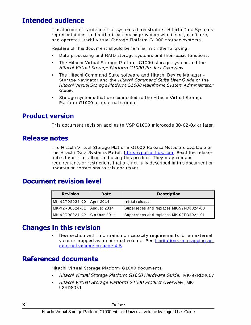
Document revision level
Changes in this revision• New section with information on capacity requirements for an external
volume mapped as an internal volume. See Limitations on mapping an external volume on page 4-5.
Referenced documentsHitachi Virtual Storage Platform G1000 documents:
• Hitachi Virtual Storage Platform G1000 Hardware Guide, MK-92RD8007
• Hitachi Virtual Storage Platform G1000 Product Overview, MK-92RD8051
Revision Date Description
MK-92RD8024-00 April 2014 Initial release
MK-92RD8024-01 August 2014 Supersedes and replaces MK-92RD8024-00
MK-92RD8024-02 October 2014 Supersedes and replaces MK-92RD8024-01

Preface xiHitachi Virtual Storage Platform G1000 Hitachi Universal Volume Manager User Guide
• Hitachi Command Suite User Guide, MK-90HC172
• Hitachi Command Suite Messages, MK-90HC178
• Hitachi Virtual Storage Platform G1000 Performance Guide, MK-92RD8012
• Hitachi Virtual Storage Platform G1000 Provisioning Guide for Mainframe Systems, MK-92RD8013
• Hitachi Virtual Storage Platform G1000 Provisioning Guide for Open Systems, MK-92RD8014
• Hitachi Virtual Storage Platform G1000 Mainframe System Administrator Guide, MK-92RD8016
• Hitachi TrueCopy® for Mainframe User Guide, MK-92RD8018
• Hitachi TrueCopy® User Guide, MK-92RD8019
• Hitachi ShadowImage® for Mainframe User Guide, MK-92RD8020
• Hitachi ShadowImage® User Guide, MK-92RD8021
• Hitachi Universal Replicator for Mainframe User Guide, MK-92RD8022
• Hitachi Universal Replicator User Guide, MK-92RD8023
• Hitachi Virtual Storage Platform G1000 Global-Active Device User Guide, MK-92RD8072
For a list of all documents for the Hitachi Virtual Storage Platform G1000 storage system, see the Hitachi Virtual Storage Platform G1000 Product Overview.
Document conventionsThis document uses the following terminology conventions:
This document uses the following typographic conventions:
Convention Description
Hitachi Virtual Storage Platform G1000, VSP G1000
Unless otherwise noted, these terms refer to all models of the Hitachi Virtual Storage Platform G1000 storage system.
Convention Description
Regular text bold In text: keyboard key, parameter name, property name, hardware label, hardware button, hardware switch
In a procedure: user interface item
Italic Variable, emphasis, reference to document title, called-out term
screen text Command name and option, drive name, file name, folder name, directory name, code, file content, system and application output, user input
< > angled brackets Variable (used when italic is not enough to identify variable)
[ ] square brackets Optional value
{ } braces Required or expected value

Hitachi Virtual Storage Platform G1000 Hitachi Universal Volume Manager User Guide
xii Preface
This document uses the following icons to draw attention to information:
Convention for storage capacity valuesPhysical storage capacity values (for example, disk drive capacity) are calculated based on the following values:
Logical storage capacity values (logical device capacity) are calculated based on the following values:
| vertical bar Choice between two or more options or arguments
{ a | b } indicates that you must choose either a or b.
Convention Description
Icon Meaning Description
Tip Provides helpful information, guidelines, or suggestions for performing tasks more effectively.
Note Provides information that is essential to the completion of a task.
Caution Warns that failure to take or avoid a specified action can result in adverse conditions or consequences (for example, loss of access to data).
WARNING Warns the user of severe conditions, consequences, or both (for example, destructive operations).
Physical capacity unit Value
1 kilobyte (KB) 1,000 (103) bytes
1 megabyte (MB) 1,000 KB or 1,0002 bytes
1 gigabyte (GB) 1,000 MB or 1,0003 bytes
1 terabyte (TB) 1,000 GB or 1,0004 bytes
1 petabyte (PB) 1,000 TB or 1,0005 bytes
1 exabyte (EB) 1,000 PB or 1,0006 bytes
Logical capacity unit Value
1 KB 1,024 (210) bytes
1 MB 1,024 KB or 1,0242 bytes
1 GB 1,024 MB or 1,0243 bytes
1 TB 1,024 GB or 1,0244 bytes
1 PB 1,024 TB or 1,0245 bytes
1 EB 1,024 PB or 1,0246 bytes
1 block 512 bytes

Preface xiiiHitachi Virtual Storage Platform G1000 Hitachi Universal Volume Manager User Guide
Accessing product documentationThe Hitachi Virtual Storage Platform G1000 user documentation is available on the Hitachi Data Systems Portal: https://portal.hds.com. Check this site for the most current documentation, including important updates that may have been made after the release of the product.
Getting helpThe Hitachi Data Systems customer support staff is available 24 hours a day, seven days a week. If you need technical support, log on to the Hitachi Data Systems Portal for contact information: https://portal.hds.com
CommentsPlease send us your comments on this document: [email protected]. Include the document title, number, and revision level (for example, -07), and refer to specific sections and paragraphs whenever possible. All comments become the property of Hitachi Data Systems Corporation.
Thank you!
1 Cyl For open systems:
• OPEN-V: 960 KB
• Other than OPEN-V: 720 KB
For mainframe systems: 870 KB
Logical capacity unit Value

Hitachi Virtual Storage Platform G1000 Hitachi Universal Volume Manager User Guide
xiv Preface

1
Overview 1–1Hitachi Virtual Storage Platform G1000 Hitachi Universal Volume Manager User Guide
Overview
With Hitachi Universal Volume Manager, you connect volumes in external storage systems to Hitachi Virtual Storage Platform G1000 (VSP G1000) and manage them as if they were one system.
This guide provides information and instructions for planning, setup, maintenance, and troubleshooting the use of external volumes with VSP G1000 and its software products.
□ Features—multiple systems, common management
□ How Universal Volume Manager works
□ Typical components

Hitachi Virtual Storage Platform G1000 Hitachi Universal Volume Manager User Guide
1–2 Overview
Features—multiple systems, common managementWhen a system consists of multiple storage systems, a host must usually be connected to all of the systems. When a system administrator configures the connections from the host to volumes, he or she follows different instructions for each of the storage systems.
With Universal Volume Manager, the administrator configures the connection from the host to the VSP G1000 storage system, then can manipulate mapped volumes in an external storage system in the same way as volumes in the VSP G1000 storage system.
Operations between storage systems can also involve different procedures. But with Universal Volume Manager, you perform them with the same Hitachi software as when you use VSP G1000 systems.
For example, you will use the desired Hitachi replication program for copy operations between VSP G1000 and the external systems, including the following:
• Copying data from a volume in VSP G1000 to a volume in the external system.
• Copying data from a volume in an external system to a volume in another external system.
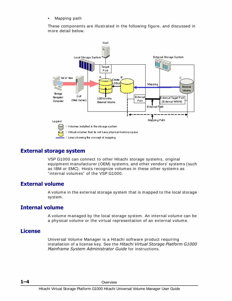
How Universal Volume Manager worksA volume in an external storage system becomes an internal volume in VSP G1000 when you map to it.
• A local system port must be connected to the external storage system port with a fibre cable. This route between ports is the "external path".
• The external volume is represented in the VSP G1000 as an internal volume, and the path between them is the “mapping path”.
• The figure below shows the connection between the local and external storage systems. In this figure, the external system is connected to the local system’s “external ports” via a switch using the Fibre-Channel interface. An “external port” is an attribute assigned to VSP G1000 ports.

Overview 1–3Hitachi Virtual Storage Platform G1000 Hitachi Universal Volume Manager User Guide
Multiple external storage systems can be connected to one external port. You can add an additional external storage system even when the external port is already in use.
Logical devices (LDEVs) are created during or after the mapping operation. If created after mapping, the LDEVs are created in the same way they are when you create normal internal volumes using Virtual LVI/Virtual LUN. As shown in the figure, LDEVs in mapped external volumes are required for use in the local system.
Typical componentsUniversal Volume Manager consists of the following components:
• VSP G1000 storage system, referred to as the “local storage system”
• Universal Volume Manager license
• An external storage system
• External volumes mapped to the local system. In the local system, the mapped external volume is referred to as an “internal volume”, and is a virtual representation of the external volume.
• LDEVs (logical devices).
• Hitachi Storage Navigator, Hitachi Command Control Interface software, and/or Hitachi Command Line Interface
• External path
Note: Mapped external volumes must be accessed and copied only by hosts that are connected to the VSP G1000, not by hosts connected to the external systems.
Hitachi Virtual Storage Platform G1000 Hitachi Universal Volume Manager User Guide
1–4 Overview
• Mapping path
These components are illustrated in the following figure, and discussed in more detail below.
External storage systemVSP G1000 can connect to other Hitachi storage systems, original equipment manufacturer (OEM) systems, and other vendors' systems (such as IBM or EMC). Hosts recognize volumes in these other systems as “internal volumes” of the VSP G1000.
External volumeA volume in the external storage system that is mapped to the local storage system.
Internal volumeA volume managed by the local storage system. An internal volume can be a physical volume or the virtual representation of an external volume.
LicenseUniversal Volume Manager is a Hitachi software product requiring installation of a license key. See the Hitachi Virtual Storage Platform G1000 Mainframe System Administrator Guide for instructions.
Overview 1–5Hitachi Virtual Storage Platform G1000 Hitachi Universal Volume Manager User Guide
Interfaces You can perform Universal Volume Manager operations using the following interfaces:
• Device Manager - Storage Navigator
• Command Control Interface
• Spreadsheets
Device Manager - Storage Navigator
The Hitachi graphical user interface used to manage the VSP G1000 system and the connected external storage volumes. Device Manager - Storage Navigator is run from a browser on the user-supplied computer. The operations described in this document are performed using Device Manager - Storage Navigator.
Hitachi Command Control Interface software (CCI)
CCI provides a command line interface to perform most of the same operations as Device Manager - Storage Navigator. CCI operations are issued directly from the host, and can be automated using scripts. External volumes can be used as remote command devices.
Spreadsheets
With spreadsheets, you can schedule and perform the following Universal Volume Manager operations.
• Map external volumes with multiple or single LDEVs to the local system
• Retrieve information about mapped external volumes
• Retrieve information about external volume groups configured to the local system
• Retrieve information about all SSIDs in the local system
• Disconnect and reconnect an external volume or an external storage system
• Delete external volume mapping
• Move an external volumes from one path group to another existing group or to a new group.

Hitachi Virtual Storage Platform G1000 Hitachi Universal Volume Manager User Guide
1–6 Overview
2
Requirements and planning 2–1Hitachi Virtual Storage Platform G1000 Hitachi Universal Volume Manager User Guide
Requirements and planning
This topic describes requirements and planning.
□ Planning workflow
□ System requirements
□ Planning considerations for external storage systems
□ Application performance considerations
□ Planning external volumes
□ Planning external paths and path groups
□ Default mapping settings

Hitachi Virtual Storage Platform G1000 Hitachi Universal Volume Manager User Guide
2–2 Requirements and planning
Planning workflowBefore mapping an external volume to VSP G1000, review the information in this chapter to make sure that you understand the Universal Volume Manager requirements and implementation procedures.
Use the general order in the following to prepare for Universal Volume Manager:
• Review System requirements on page 2-2.
• Ensure that the external system whose volumes you want to map is supported by Universal Volume Manager. See Supported external storage systems on page A-1.
• Ensure the functionality you want is supported for mapped external volumes. See Virtual Storage Platform G1000 software supported for external volumes on page 3-1.
• In the external system, select a port and set any necessary parameters. See Setting up ports on the external system on page 4-4.
• In the local system, identify the port that will connect to the external system and make sure it is specified as an “external port”. See Setting port attributes on the local system on page 4-2.
• Plan data paths from the local to the external system. See Planning external paths and path groups on page 2-14.
• In the external system, prepare volumes for use in the local system. For example, if you plan to use an external volume for replication, make sure it matches the Hitachi replication software’s requirements.
See the following for this and other considerations.
Planning external volumes on page 2-5
Mainframe volumes on page 2-7
Open systems volumes on page 2-8
Capacity requirements for volumes on page 2-9
• In the local storage system, configure external volume groups to which you will assign the external volume during the mapping operation. See External volume groups (ExGs) on page 2-8.
• You can change the defaults for some mapping settings before performing the operation. See Editing external volume policies (settings) on page 5-2.
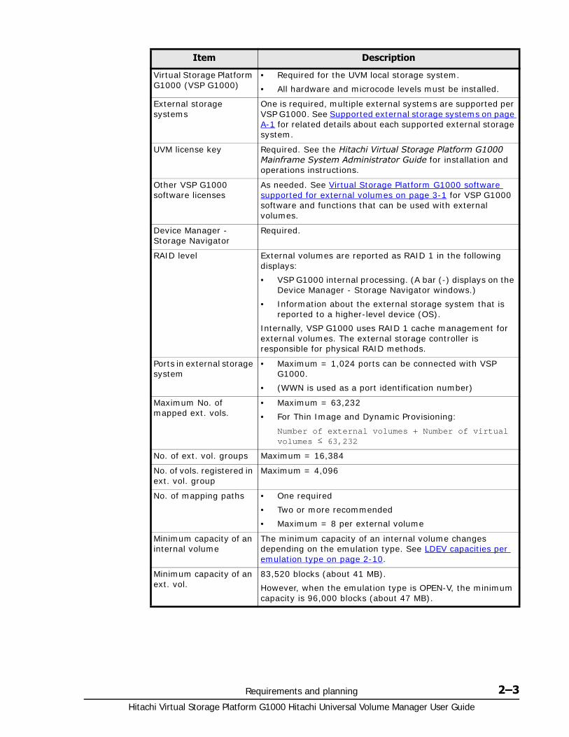
System requirementsUniversal Volume Manager (UVM) operations are performed between the local storage system—VSP G1000—and volumes in an external storage system. General requirements for these and all UVM components are described below.
Requirements and planning 2–3Hitachi Virtual Storage Platform G1000 Hitachi Universal Volume Manager User Guide
Item Description
Virtual Storage Platform G1000 (VSP G1000)
• Required for the UVM local storage system.
• All hardware and microcode levels must be installed.
External storage systems
One is required, multiple external systems are supported per VSP G1000. See Supported external storage systems on page A-1 for related details about each supported external storage system.
UVM license key Required. See the Hitachi Virtual Storage Platform G1000 Mainframe System Administrator Guide for installation and operations instructions.
Other VSP G1000 software licenses
As needed. See Virtual Storage Platform G1000 software supported for external volumes on page 3-1 for VSP G1000 software and functions that can be used with external volumes.
Device Manager - Storage Navigator
Required.
RAID level External volumes are reported as RAID 1 in the following displays:
• VSP G1000 internal processing. (A bar (-) displays on the Device Manager - Storage Navigator windows.)
• Information about the external storage system that is reported to a higher-level device (OS).
Internally, VSP G1000 uses RAID 1 cache management for external volumes. The external storage controller is responsible for physical RAID methods.
Ports in external storage system
• Maximum = 1,024 ports can be connected with VSP G1000.
• (WWN is used as a port identification number)
Maximum No. of mapped ext. vols.
• Maximum = 63,232
• For Thin Image and Dynamic Provisioning:
Number of external volumes + Number of virtual volumes ≤ 63,232
No. of ext. vol. groups Maximum = 16,384
No. of vols. registered in ext. vol. group
Maximum = 4,096
No. of mapping paths • One required
• Two or more recommended
• Maximum = 8 per external volume
Minimum capacity of an internal volume
The minimum capacity of an internal volume changes depending on the emulation type. See LDEV capacities per emulation type on page 2-10.
Minimum capacity of an ext. vol.
83,520 blocks (about 41 MB).
However, when the emulation type is OPEN-V, the minimum capacity is 96,000 blocks (about 47 MB).
Hitachi Virtual Storage Platform G1000 Hitachi Universal Volume Manager User Guide
2–4 Requirements and planning
Planning considerations for external storage systemsAn external storage system’s performance is affected by local system operations. Conversely, performance of the host and local system are affected by the attributes assigned to the external system.
Note the following regarding performance:
• Host I/O performance (sequential write performance only) to mapped volumes can be improved by setting SOM 872 to ON. For more information, call the Hitachi Data Systems Support Center.
• The performance and status of the external system affect read/write performance of the mapped external volume. A heavy load on the external system slows the processing speed of read/write operations. In this case, I/O from a mainframe host may receive a Missing Interrupt error.
• If the host connected to the local storage system issues numerous I/O to be processed by the external storage system, the commands from the host may time out.
• When you execute VSP G1000 software commands that result in more I/O processed than the external storage system can handle, the commands could time out and an error may occur.
• When you manipulate an external volume from the host, check the Path Blockade Watch time for the external volume. If the value for this setting is longer than the timeout period of the host command, the host command may time out when the power supply is off or when an error occurs in the external storage system. If host I/O is a significant concern, make sure that the Path Blockade Watch time of the external volume is the same as or shorter than the timeout period of the host command.
Application performance considerationsPerformance requirements for an application can be met when using external storage, but note the following considerations in this regard:
• Internal storage typically provides faster response times than external storage when the storage is of the same type.
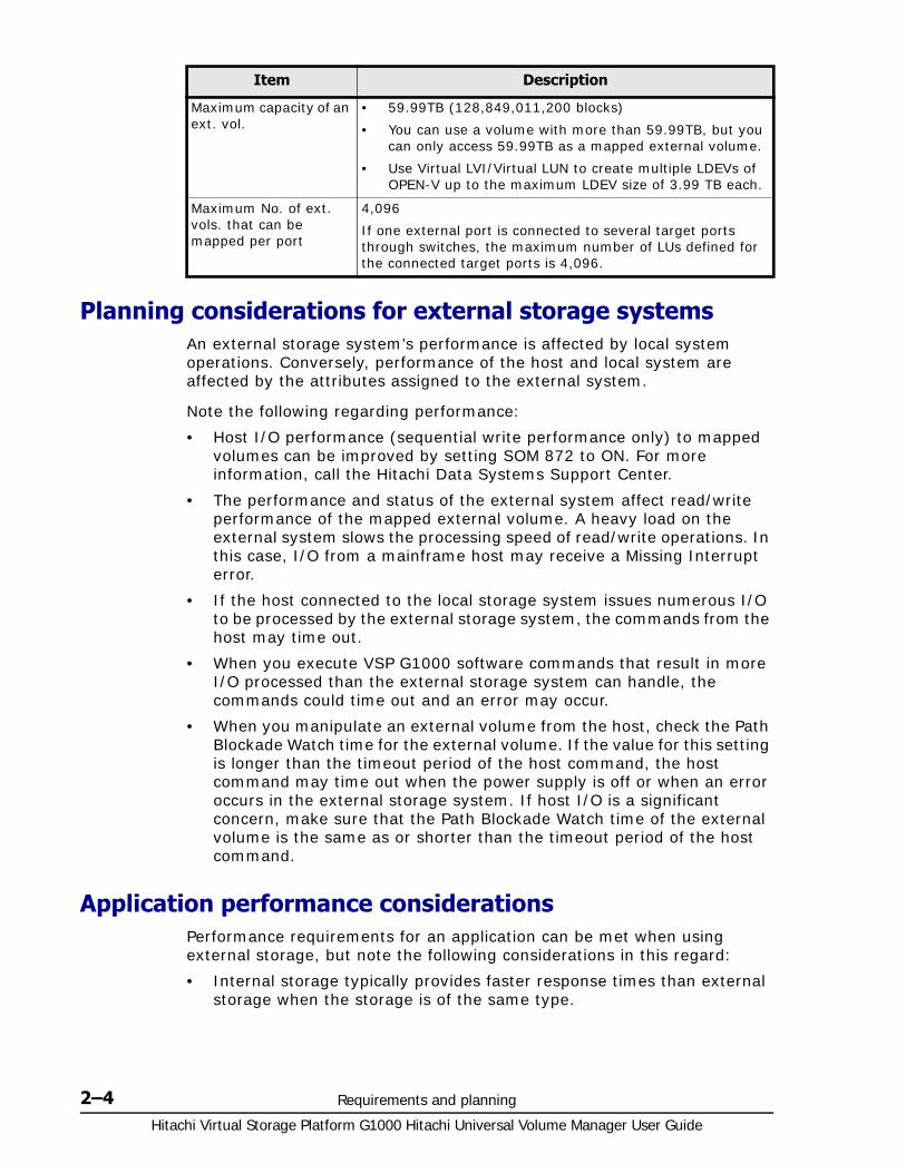
Maximum capacity of an ext. vol.
• 59.99TB (128,849,011,200 blocks)
• You can use a volume with more than 59.99TB, but you can only access 59.99TB as a mapped external volume.
• Use Virtual LVI/Virtual LUN to create multiple LDEVs of OPEN-V up to the maximum LDEV size of 3.99 TB each.
Maximum No. of ext. vols. that can be mapped per port
4,096
If one external port is connected to several target ports through switches, the maximum number of LUs defined for the connected target ports is 4,096.
Item Description
Requirements and planning 2–5Hitachi Virtual Storage Platform G1000 Hitachi Universal Volume Manager User Guide
• Storage used by the application must have the proper performance characteristics.
For example, SATA type storage does not provide the performance requirements usually needed for an OLTP application.
• The mainframe Transaction Processing Facility (TPF) does not support external storage.
Planning external volumes External volumes must be set up to match Universal Volume Manager requirements. Note the following:
• You can use pre-existing data in an external volume after it is mapped to the local system, with the following restrictions:
Emulation type must be set to OPEN-V when you map the volume.
To perform host I/O operations, an LU path from the Target port to the mapped volume must be set.
• An external volume’s maximum or minimum available capacity depends on the emulation type you specify when mapping the volume.
See Capacity requirements for volumes on page 2-9 for more information.
• Make sure that a mapped external volume is accessed only from the local VSP G1000 storage system.
Make sure that a mapped external volume is not accessed from a host that is connected to the external storage system.
Make sure that a mapped external volume is not manipulated by a copy function or any other functions of the external storage system.
Accessing a mapped external volume from the external storage system requires that the volume mapping be disconnected first.
• External volumes that are reserved by a host cannot be mapped as internal volumes. To map these volumes, cancel the reserve settings, remove host access to the volumes, and then perform the mapping operation.
• Do not map multi-platform volumes of external storage systems as internal volumes.
• When an external storage system that uses control unit path ownership is connected to VSP G1000, configure the external path to the primary controller in the external storage system as the primary path.
Ownership is the exclusive right to control volumes. A controller that has ownership is called a primary controller. If the external path is connected to a controller that does not have ownership, and the path is configured as primary path, the ownership will be transferred, which may affect performance.
• A management LU cannot be used as an external volume.
Hitachi Virtual Storage Platform G1000 Hitachi Universal Volume Manager User Guide
2–6 Requirements and planning
A management LU receives commands from an application; it controls or manages the application, and stores control information from the application. An example of a management LU is a Universal Xport LU. (A CCI command device is not a management LU.)
Before performing the external volume mapping operation, perform one of the following operations on the external storage system.
Delete the management LU from the port to be connected to the VSP G1000.
Make sure that at least one LU is used for data storage and has a smaller LUN (LU number) than the management LU’s LUN. Also make sure that the data storage LU is set to the port connected to VSP G1000.
Use the security function and configure the access attribute of the management LU to prohibit read and write operations.
An external storage system that has a management LU might not be recognized by the local storage system.
Cache use and external storage performancePerformance for external storage used with VSP G1000 is highly dependent on proper cache configuration. The Cache Mode setting, which you specify during the mapping operation, affects external storage performance.
When data is written to the mapped external volume, Cache Mode controls when the write-complete response is sent to the host,
• When Enabled is specified, the write-complete response is sent when the write data is in VSP G1000 cache.
• When Disabled is specified, the write-complete response is sent when the write data is accepted by the external system.
Disabled is the safest setting and is recommended when there is a possibility that the I/O rate will exceed the short term capabilities of the external storage.
Enabled can adversely impact overall VSP G1000 performance if the I/O rate exceeds the performance capabilities of the external system. If you specify Enabled, you must use the same formula for sizing cache in both the internal and external systems.
A cache partition must be defined when Enabled is used for the Cache Mode setting. A CLPR helps to protect overall VSP G1000 performance when the I/O rate tends to exceed the capabilities of the external system.
Cache Mode effects with other Hitachi software
Note the following additional effects regarding the Cache Mode setting:
• If you perform the Cache Residency Manager bind mode operation on an external volume, Cache Mode is set to Enabled. In this case, twice as much cache capacity as user data area capacity is required for the operation. (Bind mode is unavailable when UVM Cache Mode is set to Disable.)
Requirements and planning 2–7Hitachi Virtual Storage Platform G1000 Hitachi Universal Volume Manager User Guide
• The external volumes in a Dynamic Provisioning pool must all use the same Cache Mode setting, either Enabled or Disabled.
• Dynamic Tiering pool volumes require Cache Mode to be set to Enabled.
• Data that is not written by the host (for example, data written by ShadowImage) is asynchronously destaged to the external storage system regardless of the Cache Mode setting.
• When you set emulation type for a mainframe system, note the following:
Data written by a host using a Format Write command is asynchronously destaged to the external storage system regardless of the Cache Mode setting.
Data written by a host using other Write commands are destaged to the external storage system as configured in the Cache Mode setting.
Mainframe volumesNote the following requirements and considerations for mapping mainframe external volumes:
• Make sure that mainframe external volumes on a mainframe operating system consist of at least one LDEV before mapping.
• When multiple LDEVs exist in an external volume and numerous I/Os are made to them, read/write commands may timeout. When the commands timeout, the SIM (21D2xx) is reported.
• Set the MIH (missing interrupt handler) timer to 45 seconds (which is the recommended value) for mainframe external volumes on a mainframe operating system.
• Pre-existing mainframe volumes on an external system that are accessed by FICON channels cannot be mapped to the local storage system because VSP G1000 does not recognize these volumes
You can prepare mainframe external volumes for mapping using one of the following methods:
Zero-format the external volumes on the external system, map the volumes to VSP G1000, then perform the Write to Control Blocks operation using Virtual LVI/Virtual LUN on the local system side.

Hitachi Virtual Storage Platform G1000 Hitachi Universal Volume Manager User Guide
2–8 Requirements and planning
Map the external volumes to VSP G1000, and then format the mapped volumes on the local storage system using the Virtual LVI/Virtual LUN.
Open systems volumesNote the following requirements and considerations for mapping OPEN systems external volumes:
• OPEN systems external volumes do not require reformatting because the connection between VSP G1000 and the external system is Fibre Channel.
However, if you need to initialize the data area for the volume, format the volume using the Virtual LUN function. See the Hitachi Virtual Storage Platform G1000 Provisioning Guide for Open Systems for instructions.
• OPEN-V emulation provides the most efficient use of storage and the best performance. Also, emulation types other than OPEN-V may not retain existing data after being mapped.
External volume groups (ExGs) During the mapping operation, you assign the external volume to an external volume group. This allows you to organize external volumes used for similar purposes a group or groups.
For example, you may want to assign mapped volumes in the same external system to a specific ExG. Or, you may assign volumes used in a particular function, such as ShadowImage or Universal Replicator, to an ExG, even if the data is stored in different external storage systems.
You could also use ExGs to correspond to the external system’s physical disk grouping, such as a RAID group.
You assign external volume group numbers during the mapping procedure.
Note: The following relates to mapped volumes:
• After the mapping operation, the status of the mapped volume becomes Blockade; however, after the Write to Control Blocks operation is performed or mapped volume is formatted on the local system, the mainframe host can then access the new mainframe volume through the local VSP G1000 system's FICON channels.
• If you format the mapped volume from the external system, existing data is deleted and there are no options for retaining it. This is the reason for formatting from the local system side, as mentioned above.
For information on formatting and the Write to Control Blocks operations, see the Hitachi Virtual Storage Platform G1000 Provisioning Guide for Open Systems.

Requirements and planning 2–9Hitachi Virtual Storage Platform G1000 Hitachi Universal Volume Manager User Guide
Capacity requirements for volumes An external volume's capacity is carved into LDEVs when mapped to the local system as an internal volume. This topic provides information and instructions for calculating the capacity that the internal volume will have.
Note the following regarding internal/external volume capacity:
• The LDEV size in the internal volume varies according to the external system’s emulation type.
• An external volume whose capacity is less than the minimum LDEV capacity cannot be used.
• An external volume can be used whose capacity is less than the base LDEV capacity for the emulation type; this causes a custom-sized volume (CV) to be automatically created in the local system during mapping.
A custom volume in the local system has a minimum capacity, called minimum LDEV capacity.
Base LDEV capacity must equal or be greater than the minimum LDEV capacity.
The following figure illustrates minimum and base LDEV capacities.
Minimum LDEV capacity and Base LDEV capacity are calculated with the following formulas.
Minimum LDEV Capacity = Minimum Data Area Capacity \+ Control Information Area Capacity
Base LDEV Capacity = Base Data Area Capacity \+ Control Information Area Capacity
For volumes of mainframe systems other than 3390-A and 3390-V, capacities for the expanded control information area and the adjustment area are also necessary. For details, see LDEV capacities per emulation type on page 2-10.
If the external volume capacity is less than the minimum LDEV capacity, the emulation type cannot be specified.

Hitachi Virtual Storage Platform G1000 Hitachi Universal Volume Manager User Guide
2–10 Requirements and planning
• An external volume whose capacity is more than the base LDEV capacity for the emulation type results in multiple LDEVs created when the volume is mapped. These LDEVs will have the base LDEV capacity.
• When using VLL, a maximum 2,048 CVs can be created.
(VLL is not supported for the OPEN-L emulation type.)
• For emulation types other than OPEN-V, usable capacity in the internal volume is the capacity of the external volume minus control information area capacity.
• Data above the maximum capacity cannot be accessed.
LDEV capacities per emulation type
The following table shows LDEV capacities for each emulation type in units of blocks and cylinders. The number of cylinders in this section is calculated as:1 cylinder = 1,740 blocks.
Figure 2-1 Idea of LDEV capacity
Emulation Type
Minimum Data Area Capacity Base Area Capacity Control Information
Area Capacity
Blocks Cylinders Blocks Cylinders Blocks Cylinders
Volume for open systems
OPEN-3 72,000 - 4,806,720 - 11,520 -
OPEN-8 72,000 - 14,351,040 - 338,880 -
OPEN-9 72,000 - 14,423,040 - 338,880 -
OPEN-E 72,000 - 28,452,960 - 27,360 -
OPEN-K 72,000 - 3,661,920 - 12,960 -
OPEN-L 71,192,160 - 71,192,160 - 10,080 -
OPEN-V 96,000 - 8,589,934,592 - 0 -

Requirements and planning 2–11Hitachi Virtual Storage Platform G1000 Hitachi Universal Volume Manager User Guide
Example: Determining capacity for OPEN-3 volume
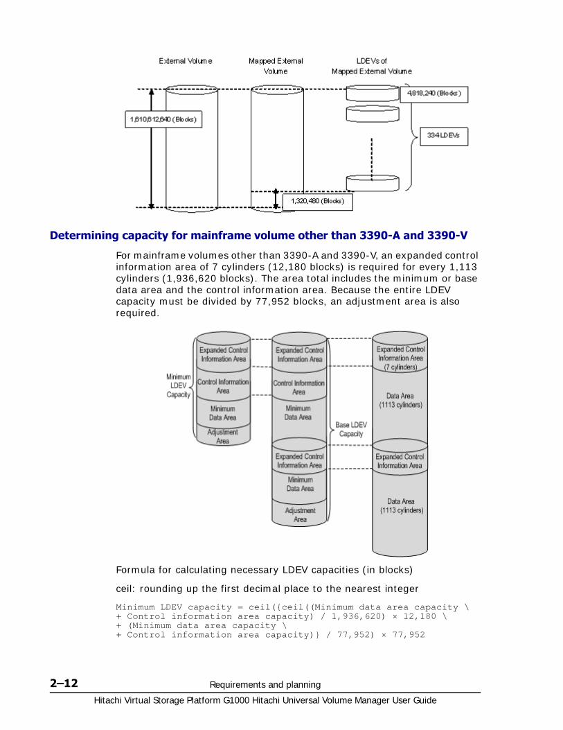
The following figure illustrates capacity for an external volume with OPEN-3 emulation type. The capacity is 1,610,612,640 blocks. Using the data for OPEN-3 in LDEV capacities per emulation type on page 2-10, 334 LDEVS can be created from the base LDEV capacity of 4,818,240 blocks (Base Data Area plus Control Information Area).
This results in 1,320,480 blocks of the mapped external volume becoming free space. LDEVs can be created in free space using VLL.
Volume for mainframe systems
3390-1 87,000 50 1,936,620 1,113 8,700 5
3390-2 87,000 50 3,873,240 2,226 10,440 6
3390-3 87,000 50 5,809,860 3,339 10,440 6
3390-9 87,000 50 17,429,580 10,017 43,500 25
3390-L 87,000 50 57,002,400 32,760 40,020 23
3390-M 87,000 50 114,004,800 65,520 92,220 53
3390-A2 1,936,620 1,113 457,042,320 262,668 12,180 7
3390-V 87,000 50 1,944,902,400 1,117,760 0 0
Intermediate volume
3390-3A 87,000 50 5,809,860 3,339 10,440 6
3390-3B 87,000 50 5,809,860 3,339 10,440 6
3390-3C 87,000 50 5,809,860 3,339 10,440 6
3390-9A 87,000 50 17,429,580 10,017 43,500 25
3390-9B 87,000 50 17,429,580 10,017 43,500 25
3390-9C 87,000 50 17,429,580 10,017 43,500 25
3390-LA 87,000 50 57,002,400 32,760 40,020 23
3390-LB 87,000 50 57,002,400 32,760 40,020 23
3390-LC 87,000 50 57,002,400 32,760 40,020 23
3390-MA
87,000 50 114,004,800 65,520 92,220 53
3390-MB
87,000 50 114,004,800 65,520 92,220 53
3390-MC
87,000 50 114,004,800 65,520 92,220 53
Note:
For 3390-A, the control information area is required for each 1,113 cylinders.
Emulation Type
Minimum Data Area Capacity Base Area Capacity Control Information
Area Capacity
Blocks Cylinders Blocks Cylinders Blocks Cylinders
Hitachi Virtual Storage Platform G1000 Hitachi Universal Volume Manager User Guide
2–12 Requirements and planning
Determining capacity for mainframe volume other than 3390-A and 3390-V
For mainframe volumes other than 3390-A and 3390-V, an expanded control information area of 7 cylinders (12,180 blocks) is required for every 1,113 cylinders (1,936,620 blocks). The area total includes the minimum or base data area and the control information area. Because the entire LDEV capacity must be divided by 77,952 blocks, an adjustment area is also required.
Formula for calculating necessary LDEV capacities (in blocks)
ceil: rounding up the first decimal place to the nearest integer
Minimum LDEV capacity = ceil({ceil((Minimum data area capacity \ + Control information area capacity) / 1,936,620) × 12,180 \ + (Minimum data area capacity \+ Control information area capacity)} / 77,952) × 77,952

Requirements and planning 2–13Hitachi Virtual Storage Platform G1000 Hitachi Universal Volume Manager User Guide
LDEV capacity = ceil({ceil((Base data area capacity \ + Control information area capacity) / 1,936,620) × 12,180 \ + (Base data area capacity \+ Control information area capacity)} / 77,952) × 77,952
Minimum LDEV capacity and Base LDEV capacity for mainframe systems
Adjusting volume capacities for pairs
Mapped external volumes can be used for replication. All VSP G1000 replication software requires a pair’s secondary volume (S-VOL) to have the same capacity as the primary volume (P-VOL).
If you need to adjust the capacity of the VSP G1000 volume or the external volume before creating the pair, proceed as shown in the following subtopics.
Decreasing the size of the VSP G1000 S-VOL
When the VSP G1000 volume S-VOL is larger than the mapped external volume P-VOL, adjust the VSP G1000 volume’s capacity as follows:
1. Map the external volume with emulation type OPEN-V.
2. Make sure the VSP G1000 volume’s emulation type is OPEN-V.
3. Decrease the size of the VSP G1000 S-VOL by creating a custom volume (CV) using Virtual LVI/Virtual LUN, as shown in the following figure.
Emulation type Minimum LDEV capacity (blocks)
Base LDEV capacity (blocks)
3390-1 155,904 2,026,752
3390-2 155,904 3,975,552
3390-3 155,904 5,924,352
3390-9 155,904 17,617,152
3390-L 155,904 57,450,624
3390-M 233,856 114,823,296

Hitachi Virtual Storage Platform G1000 Hitachi Universal Volume Manager User Guide
2–14 Requirements and planning
Base the CV capacity on Blocks, which displays in the Capacity column on the LDEV Information dialog box in Device Manager - Storage Navigator. See the Hitachi Virtual Storage Platform G1000 Provisioning Guide for Open Systems and the Hitachi Virtual Storage Platform G1000 Provisioning Guide for Mainframe Systems for instructions on creating CVs.
4. Create the pair.
Decreasing the size of the external volume S-VOL
When the mapped external volume S-VOL is larger than the VSP G1000 P-VOL, adjust the external volume’s capacity as follows:
1. Map the external volume with the same emulation type as the VSP G1000 primary volume.
2. After mapping, check the new internal volume’s capacity. If it is larger than the VSP G1000 P-VOL, decrease the size by creating a CV that is the same size as the VSP G1000 P-VOL using Virtual LVI/Virtual LUN (see the following figure).
3. Create the pair.
Planning external paths and path groups The external path is the physical link from the local storage system port to the external storage system port. You prepare the ports on the local and external systems and then set up the external path prior to mapping your external volumes.
To prepare and set up ports, see the following sections:
• Setting port attributes on the local system on page 4-2
• Setting up ports on the external system on page 4-4
External pathsA path consists of cables and possibly switches. You configure your path according to bandwidth considerations, which include distance, speed, and performance requirements.

Requirements and planning 2–15Hitachi Virtual Storage Platform G1000 Hitachi Universal Volume Manager User Guide
Because workload can spike and cable or switch failures can occur, Hitachi strongly recommends that you set up redundant external paths. A maximum of eight paths can be used per mapped external volume. Multiple paths—redundancy—allows you to perform I/O operations with external volumes regardless of workload and/or path failure.
With multiple paths, the external storage system determines how they are used: some systems use one primary path with alternates available as backups (Single path mode); other systems allow all paths to be used at the same time, distributing I/O among them (Multi path mode). The path storage system’s mode cannot be changed. With both modes, you place the paths in path groups and prioritize each path.
Single path mode
For Single path mode, the external path with the highest priority (primary path) is used to execute I/O to the external volume. If the primary path cannot be used, it is switched to an alternative path, after a 3-minute period.
The following figure illustrates how failure is handled with redundant paths in Single path mode.

Hitachi Virtual Storage Platform G1000 Hitachi Universal Volume Manager User Guide
2–16 Requirements and planning
When you restore a path with higher priority than the currently-used path, I/O is switched to the restored path.
Multi path mode
For Multi path mode, all paths are used for I/O to the external volume. This distributes workload in a round-robin process.
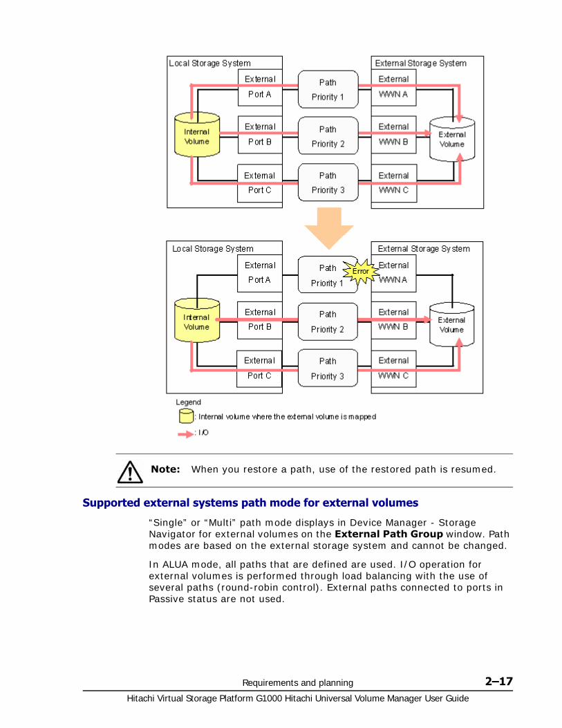
The following figure illustrates how failure is handled with redundant paths in Multi mode.
Requirements and planning 2–17Hitachi Virtual Storage Platform G1000 Hitachi Universal Volume Manager User Guide
Supported external systems path mode for external volumes
“Single” or “Multi” path mode displays in Device Manager - Storage Navigator for external volumes on the External Path Group window. Path modes are based on the external storage system and cannot be changed.
In ALUA mode, all paths that are defined are used. I/O operation for external volumes is performed through load balancing with the use of several paths (round-robin control). External paths connected to ports in Passive status are not used.
Note: When you restore a path, use of the restored path is resumed.
Hitachi Virtual Storage Platform G1000 Hitachi Universal Volume Manager User Guide
2–18 Requirements and planning
Load Balance Mode
When the path mode of an external volume is Multi or ALUA, you can select an I/O control system for the external storage system.
• Depend on the selected external volume(s): If Enable is set for ALUA Settable on the external volume, Normal Round-robin is set for Load Balance Mode automatically. If Disable is set for ALUA Settable, Disable is set for Load Balance Mode automatically.
• Normal Round-robin: Normal multi-path I/O control system. This distributes I/O to several paths on which I/O operation is enabled for the external storage system. Specify this if Extended Round-robin may lower I/O performance. This mode is recommended when the number of sequential I/O operations is small.
• Extended Round-robin: Extended multi-path I/O control system. I/O is distributed to several paths on which I/O operation is enabled for the external storage system. For sequential I/O, the external volume is divided into sections at regular intervals. In this case, the same path is used for I/O within the same section which reduces the frequency of I/O distribution. Read speed can be improved by using the cache function of the external storage system for sequential I/O operations. This mode is recommended when the number of sequential I/O operations is large.
• Disable: I/O operation is performed with only one path that is normal and has the highest priority. The same operation applies as that for Single path mode. When Disable is set for Load Balance Mode, load distribution is not performed. This mode is not recommended.
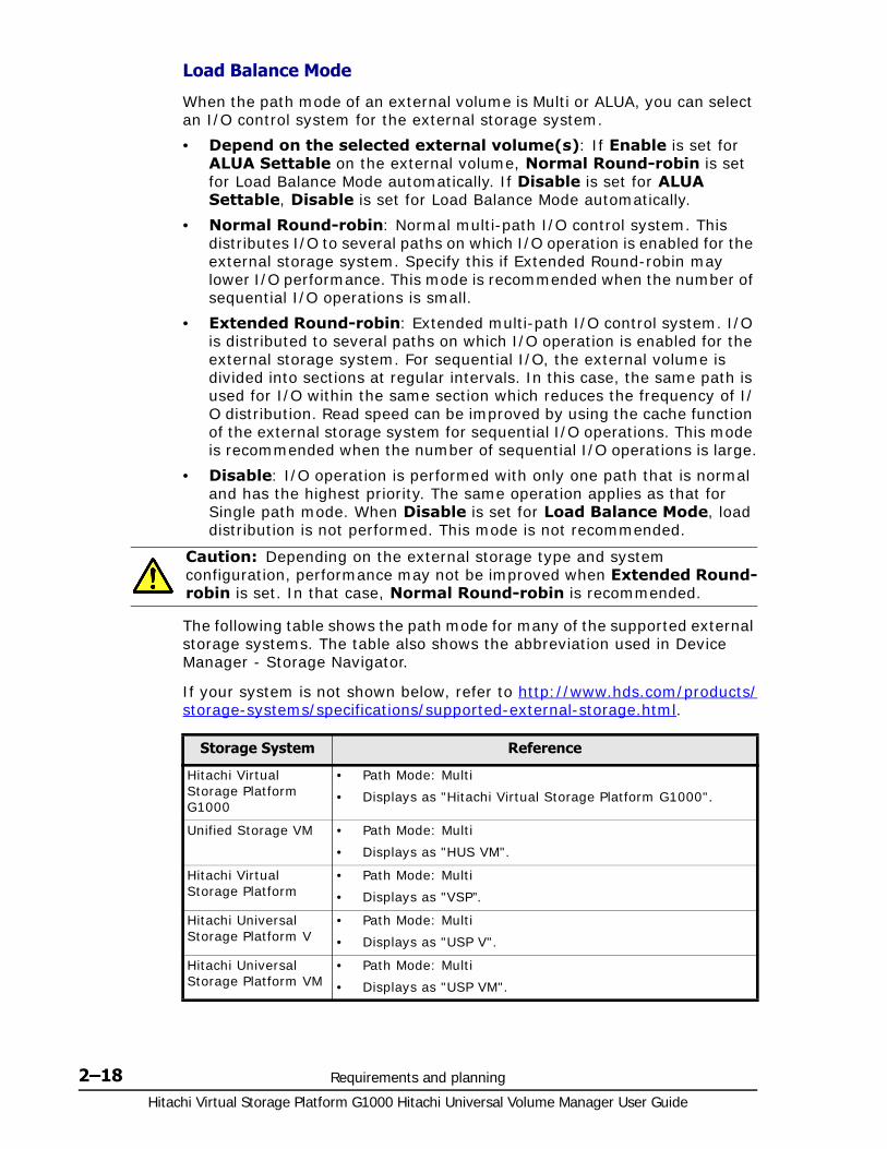
The following table shows the path mode for many of the supported external storage systems. The table also shows the abbreviation used in Device Manager - Storage Navigator.
If your system is not shown below, refer to http://www.hds.com/products/storage-systems/specifications/supported-external-storage.html.
Caution: Depending on the external storage type and system configuration, performance may not be improved when Extended Round-robin is set. In that case, Normal Round-robin is recommended.
Storage System Reference
Hitachi Virtual Storage Platform G1000
• Path Mode: Multi
• Displays as "Hitachi Virtual Storage Platform G1000".
Unified Storage VM • Path Mode: Multi
• Displays as "HUS VM".
Hitachi Virtual Storage Platform
• Path Mode: Multi
• Displays as "VSP”.
Hitachi Universal Storage Platform V
• Path Mode: Multi
• Displays as "USP V".
Hitachi Universal Storage Platform VM
• Path Mode: Multi
• Displays as "USP VM".

Requirements and planning 2–19Hitachi Virtual Storage Platform G1000 Hitachi Universal Volume Manager User Guide
Hitachi TagmaStore® Universal Storage Platform
• Path Mode: Multi
• Displayed "USP".
Hitachi TagmaStore® Universal Storage Platform
• Path Mode: Multi
• Displays as "NSC".
Hitachi Unified Storage
• Path Mode: Multi
• Displays as "HUS".
Hitachi Adaptable Modular Storage
• Path Mode:
- Multi: AMS2500, AMS2300, AMS2100, or AMS2010
- Single: AMS1000, AMS500, or AMS200
• Displays as "AMS".
Hitachi Workgroup Modular Storage
• Path Mode: Single
• Displays as "WMS".
Hitachi Simple Modular Storage
• Path Mode: Multi
• Displays as "SMS".
Hitachi Lightning 9900 V Series
• Path Mode: Multi
• Displays as "9970V" and "9980V".
Hitachi Lightning 9900 Series
• Path Mode: Multi
• Displays as:
- Lightning 9960: "0400".
- Lightning 9910: "0401".
Hitachi Thunder 9500V series
• Path Mode: Single
• Displays as "9500V".
Hitachi SANRISE Universal Storage Platform
• Path Mode: Multi
• Displays as "USP".
Hitachi SANRISE Network Storage Controller
• Path Mode: Multi
• Displays as "NSC".
Hitachi SANRISE 9900V series
• Path Mode: Multi
• Displays as "9970V" and "9980V".
Hitachi SANRISE 9500V series
• Path Mode: Single
• Displays as "9500V".
Hitachi SANRISE 2000 series
• Path Mode: Multi
• Displays as:
- SANRISE 2800: "0400".
- SANRISE 2200: "0401".
HP Virtual Storage Platform VX7
• Path Mode: Multi
• Displays as "XP7”.
HP Virtual Storage Platform VP9500
• Path Mode: Multi
• Displays as "P9500".
A/H-6593 • Path Mode: Multi
• Displays as "300".
Storage System Reference

Hitachi Virtual Storage Platform G1000 Hitachi Universal Volume Manager User Guide
2–20 Requirements and planning
External path configurations — direct and switch This topic provides recommendations for setting up direct and switch external path configurations.
HP H24000 • Path Mode: Multi
• Displays as "24000".
HP H20000 • Path Mode: Multi
• Displays as "20000".
HP SANRISE H12000 • Path Mode: Multi
• Displays as "12000".
HP SANRISE H10000 • Path Mode: Multi
• Displays as "10000".
HP SANRISE H1024/H128
• Path Mode: Multi
• Displays as "1024" and "128".
HP SANRISE H512/H48
• Path Mode: Multi
• Displays as "512" and "48".
HP SANRISE H256 • Path Mode: Multi
• Displays as "256".
HP XP7 • Path Mode: Multi
• Displays as "XP7”.
HP StorageWorks P9500
• Path Mode: Multi
• Displays as "P9500".
HP XP24000 • Path Mode: Multi
• Displays as "24000".
HP XP20000 • Path Mode: Multi
• Displays as "20000".
HP XP12000 • Path Mode: Multi
• Displays as "12000".
HP XP10000 • Path Mode: Multi
• Displays as "10000".
HP XP1024/XP128 • Path Mode: Multi
• Displays as "1024" and "128".
HP XP512/XP48 • Path Mode: Multi
• Displays as "512" and "48".
HP XP256 • Path Mode: Multi
• Displays as "256".
HP StorageWorks Enterprise Virtual Array 3000/4000/5000/6000/8000
• Path Mode: Single
• Displays as "EVA".
SVS200 • Path Mode: Multi
• Displays as "SVS200".
Storage System Reference

Requirements and planning 2–21Hitachi Virtual Storage Platform G1000 Hitachi Universal Volume Manager User Guide
Direct connection
The following figure shows redundant paths in a direct connection configuration. External storage system ports, "WWN A" and "WWN B", are connected to the local system ports, "CL1-A" and "CL2-A" (which are specified as external ports). For greater redundancy, Path 2, the alternate path, uses ports of a different cluster in both the local and external storage systems.
Switch connection
The following figure shows redundant paths with switches. Ports in the local system are connected to ports in the external system through the switch. The paths use ports of different clusters for increased redundancy.

Hitachi Virtual Storage Platform G1000 Hitachi Universal Volume Manager User Guide
2–22 Requirements and planning
Default mapping settingsMapped volumes have default values that you can use or change before (or after) mapping.
See Editing external volume policies (settings) on page 5-2 to review the settings and edit them if desired.

3
Virtual Storage Platform G1000 software supported for external volumes 3–1Hitachi Virtual Storage Platform G1000 Hitachi Universal Volume Manager User Guide
Virtual Storage Platform G1000software supported for external
volumes
You will use Virtual Storage Platform G1000 storage software products and functionality to manage and manipulate data in your mapped volumes: for example, Virtual LVI/Virtual LUN, TrueCopy, LUN Manager, and so on.
This topic provides requirements and restrictions for the Hitachi software supported with external volumes.
□ Cache Residency Manager
□ Thin Image
□ Dynamic Provisioning, Dynamic Provisioning for Mainframe, Dynamic Tiering, Dynamic Tiering for Mainframe, and Thin Image
□ Global-active device
□ Local replication software
□ LUN Manager and Configuration File Loader
□ Performance Monitor
□ Remote replication software
□ SNMP Agent
□ Virtual LVI/LUN (VLL)

Hitachi Virtual Storage Platform G1000 Hitachi Universal Volume Manager User Guide
3–2 Virtual Storage Platform G1000 software supported for external volumes
Cache Residency Manager Review the following when using external volumes with Cache Residency Manager:
• If you set bind mode, a cache of twice as much capacity as the user data area of the mapped volume is required for the Cache Residency Manager operation.
• Bind mode cannot be specified for an external volume if the Cache Mode is set to Disable You can specify the Cache Mode setting before, during, or after mapping. See Editing external volume policies (settings) on page 5-2 for more information.
Thin ImageMapped volumes can be used in pairs for Thin Image, with the following restrictions:
• Both internal and external volumes cannot be used together in the same pool.
• All external volumes in a pool must use the same Cache Mode setting.
After mapping and formatting an external volume, it is ready to use as a pair volume. The following figure shows an example of an external volume used as a Pool-Vol.

Virtual Storage Platform G1000 software supported for external volumes 3–3Hitachi Virtual Storage Platform G1000 Hitachi Universal Volume Manager User Guide
Dynamic Provisioning, Dynamic Provisioning for Mainframe, Dynamic Tiering, Dynamic Tiering for Mainframe, and Thin Image
Mapped external volumes can be used as pool volumes for Dynamic Provisioning, Dynamic Provisioning for Mainframe, Dynamic Tiering, Dynamic Tiering for Mainframe, and Thin Image.
• A mapped volume that is used as a pool volume must use OPEN-V emulation for open systems and 3390-V emulation for mainframe systems.
• All external volumes in the same pool must use the same Cache Mode setting. For more information about this setting, see Cache use and external storage performance on page 2-6.
• With Dynamic Tiering, the Cache Mode setting must be Enabled.
Global-active deviceMapped external volumes can be used as the global-active device quorum disk. They cannot be used as global-active device pair volumes.
Local replication softwareMapped volumes can be used in pairs for ShadowImage and ShadowImage for Mainframe.
After mapping and formatting an external volume, it is ready to use as a pair volume. The following figure shows an example of an external volume used as an S-VOL.
Hitachi Virtual Storage Platform G1000 Hitachi Universal Volume Manager User Guide
3–4 Virtual Storage Platform G1000 software supported for external volumes
LUN Manager and Configuration File LoaderUse LUN Manager to set the LU path for the mapped volume with OPEN systems emulation types.
Some LUN Manager operations can be performed using spreadsheets and the Configuration File Loader function. When using external volumes, you can use Configuration File Loader for the following operations:
• Set the LU path definition for an external volume (add, delete, or change LU paths).
• Set an external volume as a command device (add or delete the setting).
• Setting the channel adapter (CHA) mode, host group, and WWN for the external port is not supported. When an external volume is mapped through an external port, the port setting operation of the topology is not available.
Performance MonitorPerformance Monitor can be used to display monitoring information for mapped external volumes.
Remote replication software Mapped external volumes can be used with the following remote replication software:
• TrueCopy
• TrueCopy for Mainframe
• Universal Replicator
• Universal Replicator for Mainframe
After mapping and formatting an external volume, it is ready to use as a pair volume. The following figures show examples of an external volume used as an S-VOL.

Virtual Storage Platform G1000 software supported for external volumes 3–5Hitachi Virtual Storage Platform G1000 Hitachi Universal Volume Manager User Guide
SNMP Agent Information about both the mapped external volume and the External port can be displayed by SNMP Agent.
Virtual LVI/LUN (VLL) For mainframe external volumes, use the Virtual LVI function to format or to perform the Write to Control Blocks operation immediately after mapping. See the Hitachi Virtual Storage Platform G1000 Provisioning Guide for Mainframe Systems for information.
If you create LDEVs from an external volume using the Virtual LVI or Virtual LUN function, the Cache Mode setting of the created LDEVs is the same as the mapped external volume.
Figure 3-1 UR and URz example using a mapped external volume
Figure 3-2 TC and TCz example using a mapped external volume

Hitachi Virtual Storage Platform G1000 Hitachi Universal Volume Manager User Guide
3–6 Virtual Storage Platform G1000 software supported for external volumes
4
Setting up external volumes 4–1Hitachi Virtual Storage Platform G1000 Hitachi Universal Volume Manager User Guide
Setting up external volumes
You set up ports and external paths, map the external volume, then begin using it with native storage on the VSP G1000. This topic provides setup procedures and information.
□ Setup workflow
□ Setting port attributes on the local system
□ Setting up ports on the external system
□ Limitations on mapping an external volume
□ Mapping an external volume
□ Preparing mapped volumes for use
□ Using mapped volumes
□ Recognizing the local system from the external system

Hitachi Virtual Storage Platform G1000 Hitachi Universal Volume Manager User Guide
4–2 Setting up external volumes
Setup workflow When you begin setting up Universal Volume Manager, all planning tasks and considerations must be completed. Consult the topics in Planning workflow on page 2-2 to review.
Set up external volumes as follows:
1. Set up ports on the local and external storage systems. See the following:
Setting port attributes on the local system on page 4-2
Setting up ports on the external system on page 4-4
2. To edit certain mapping settings prior to the mapping operation, see Editing external volume policies (settings) on page 5-2. Otherwise, you can make changes during the operation or accept the default settings.
3. Map the external volume as the internal volume.
You can read the existing data of a mapped internal volume from the local storage system if you set the emulation type of the external volume to OPEN-V and the number of LDEVs per external volume to 1.
For more information, see Mapping an external volume on page 4-5.
4. When the external volume is successfully mapped, perform the one of the following based on the volume’s emulation type:
For mainframe emulations, format the volume or perform the Write to Control Blocks operation using Virtual LVI. See the Hitachi Virtual Storage Platform G1000 Provisioning Guide for Mainframe Systems.
For OPEN-system emulation, define LU paths to a host using LUN Manager. See the Hitachi Virtual Storage Platform G1000 Provisioning Guide for Open Systems.
See Also:
Recognizing the local system from the external system on page 4-13.
Setting port attributes on the local systemThe port attribute of a local storage system connected to an external storage system must be specified as "External". For information on setting up ports, see the user guide of the external storage system that you are using.
Prerequisite information
• Before changing the port’s attribute, release LU paths that may be assigned to the port.
• Ports with RCU target and Initiator attributes can be changed to External, but confirm that they are no longer used for remote copy operations.
• For more information about setting up the external path, see Planning external paths and path groups on page 2-14.
Required Role

Setting up external volumes 4–3Hitachi Virtual Storage Platform G1000 Hitachi Universal Volume Manager User Guide
• Storage Administrator (System Resource Management)
1. Open the External Storage window.
In the Hitachi Command Suite:a. On the Resources tab, click Storage Systems, and then expand
All Storage Systems.b. Expand the target storage system, and then click Ports/Host
Groups.
In Device Manager - Storage Navigator (mainframe only environment) a. Click Storage Systems, and then expand the Storage Systems
tree.b. Click Ports/Host Groups.
2. In the Ports/Host Groups window, click the Ports tab.
3. On the Ports tab, select the desired port row, and then click Edit Ports.
4. In the Edit Ports window, select External in the Port Attribute box.
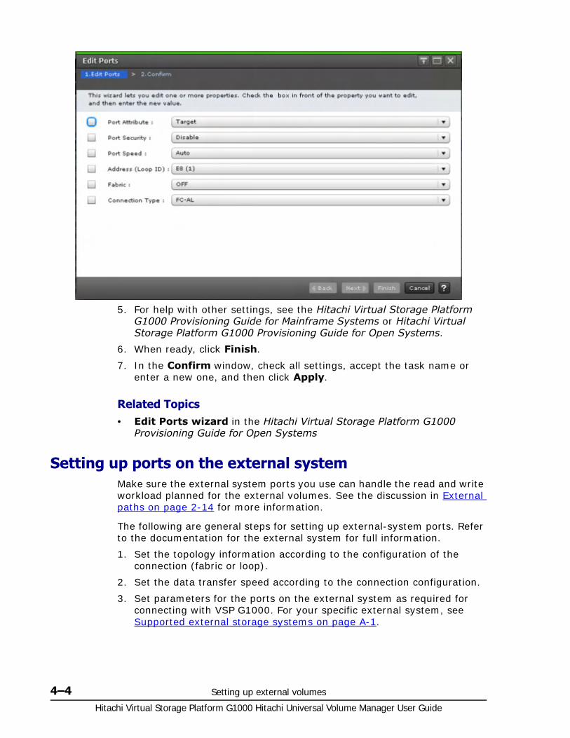
Hitachi Virtual Storage Platform G1000 Hitachi Universal Volume Manager User Guide
4–4 Setting up external volumes
5. For help with other settings, see the Hitachi Virtual Storage Platform G1000 Provisioning Guide for Mainframe Systems or Hitachi Virtual Storage Platform G1000 Provisioning Guide for Open Systems.
6. When ready, click Finish.
7. In the Confirm window, check all settings, accept the task name or enter a new one, and then click Apply.
Related Topics• Edit Ports wizard in the Hitachi Virtual Storage Platform G1000
Provisioning Guide for Open Systems
Setting up ports on the external systemMake sure the external system ports you use can handle the read and write workload planned for the external volumes. See the discussion in External paths on page 2-14 for more information.
The following are general steps for setting up external-system ports. Refer to the documentation for the external system for full information.
1. Set the topology information according to the configuration of the connection (fabric or loop).
2. Set the data transfer speed according to the connection configuration.
3. Set parameters for the ports on the external system as required for connecting with VSP G1000. For your specific external system, see Supported external storage systems on page A-1.
Setting up external volumes 4–5Hitachi Virtual Storage Platform G1000 Hitachi Universal Volume Manager User Guide
If you do not find your external system in the section, see http://www.hds.com/products/storage-systems/specifications/supported-external-storage.html to make sure your system is supported, then refer to the documentation for the system’s ports.
4. Define LUNs and present them on the port on the external system.
Limitations on mapping an external volumeAfter connecting a port to the external storage system, an external volume can be mapped as an internal volume. Make sure to check the capacity requirements of the external volume you intend to map as an internal volume.
Following are the limitations on mapping an external volume:
• You cannot access data that is stored in an area that exceeds the maximum capacity of the external volume. For example, if you map 100GB of an external volume as 70GB of the internal volume, 30GB of the external volume cannot be accessed from the local storage system side.
• You cannot map an external volume which does not meet the minimum capacity requirement. For example, you cannot map 10GB of the external volume as an internal volume with a minimum capacity requirement of 30GB.
Mapping an external volumeAfter setting the attribute of the port used for Universal Volume Manager to the external port, you can map the external volume as an internal volume.
Prerequisite information
• Attributes set for the external volume before mapping, such as port security, LUN security, Volume Retention Manager attributes, and so on are discarded when the external volume is mapped. If the original attributes are required, reset them in the local storage system after mapping.
• When the external volume is a command device, it is mapped as a remote command device. For important information about mapping command devices, see Remote command devices on page B-1.
• Before you map the external volume, check whether any application is using the volume. If so, stop the application before mapping.

Hitachi Virtual Storage Platform G1000 Hitachi Universal Volume Manager User Guide
4–6 Setting up external volumes
For example, if mapping a command device, make sure CCI commands are not being executed during the mapping operation.
Required Role
• Storage Administrator (Provisioning)
1. Open the External Storage window.
In the Hitachi Command Suite:a. On the Resources tab, click Storage Systems, and then expand
All Storage Systems.b. Expand the target storage systems, right-click External Storage,
and then select System GUI.
In Device Manager - Storage Navigator (mainframe only environment) a. Click Storage Systems, and then expand the Storage Systems
tree.b. Click External Storage.
2. On the External Storage Systems tab, click Add External Volumes.
3. In the Add External Volumes window, add the external volume by clicking either By New External Path Group or By Existing External Path Group.
Note: When you create an LDEV at the same time that you map an external volume, you cannot select the following LDEV numbers:
• Numbers already in use.
• Numbers already assigned to another emulation group (grouped every 32 LDEV numbers).
• Numbers not assigned to the user.
• Model/serial number and LDEV ID/virtual LDEV ID of the storage system and the virtual storage machine do not match in the mainframe volume or the interim volume that you create.
For emulation groups, see Hitachi Virtual Storage Platform G1000 Provisioning Guide for Open Systems or Hitachi Virtual Storage Platform G1000 Provisioning Guide for Mainframe Systems. To determine whether the LDEV number can be assigned, click the View LDEV IDs button in the Add External Volumes window when you map the external volume.
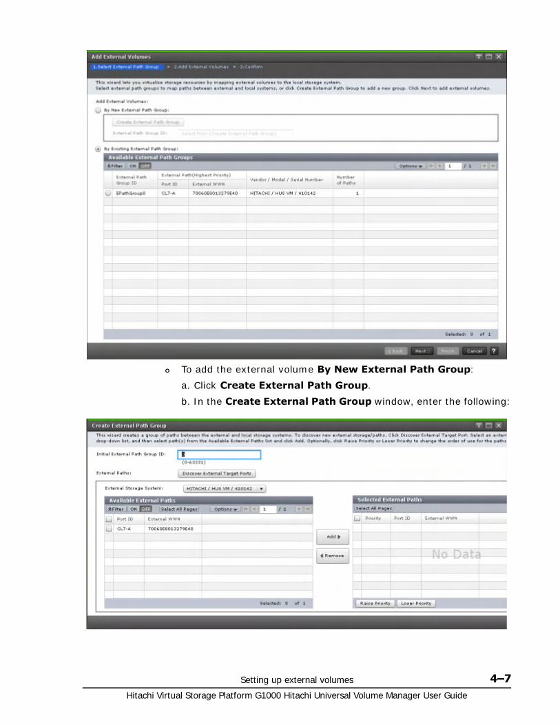
Setting up external volumes 4–7Hitachi Virtual Storage Platform G1000 Hitachi Universal Volume Manager User Guide
To add the external volume By New External Path Group:
a. Click Create External Path Group.
b. In the Create External Path Group window, enter the following:
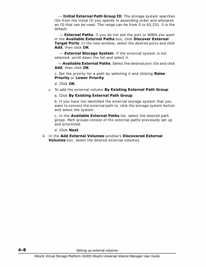
Hitachi Virtual Storage Platform G1000 Hitachi Universal Volume Manager User Guide
4–8 Setting up external volumes
— Initial External Path Group ID. The storage system searches IDs from the initial ID you specify in ascending order and allocates an ID that can be used. The range can be from 0 to 63,231. 0 is the default.
— External Paths. If you do not see the port or WWN you want in the Available External Paths box, click Discover External Target Ports. In the new window, select the desired ports and click Add, then click OK.
— External Storage System. If the external system is not selected, scroll down the list and select it.
— Available External Paths. Select the desired port IDs and click Add, then click OK.
c. Set the priority for a path by selecting it and clicking Raise Priority or Lower Priority.
d. Click OK.
To add the external volume By Existing External Path Group:
a. Click By Existing External Path Group.
b. If you have not identified the external storage system that you want to connect the external path to, click the storage system button and select the system.
c. In the Available External Paths list, select the desired path group. Path groups consist of the external paths previously set up and prioritized.
d. Click Next.
4. In the Add External Volumes window’s Discovered External Volumes box, select the desired external volumes.
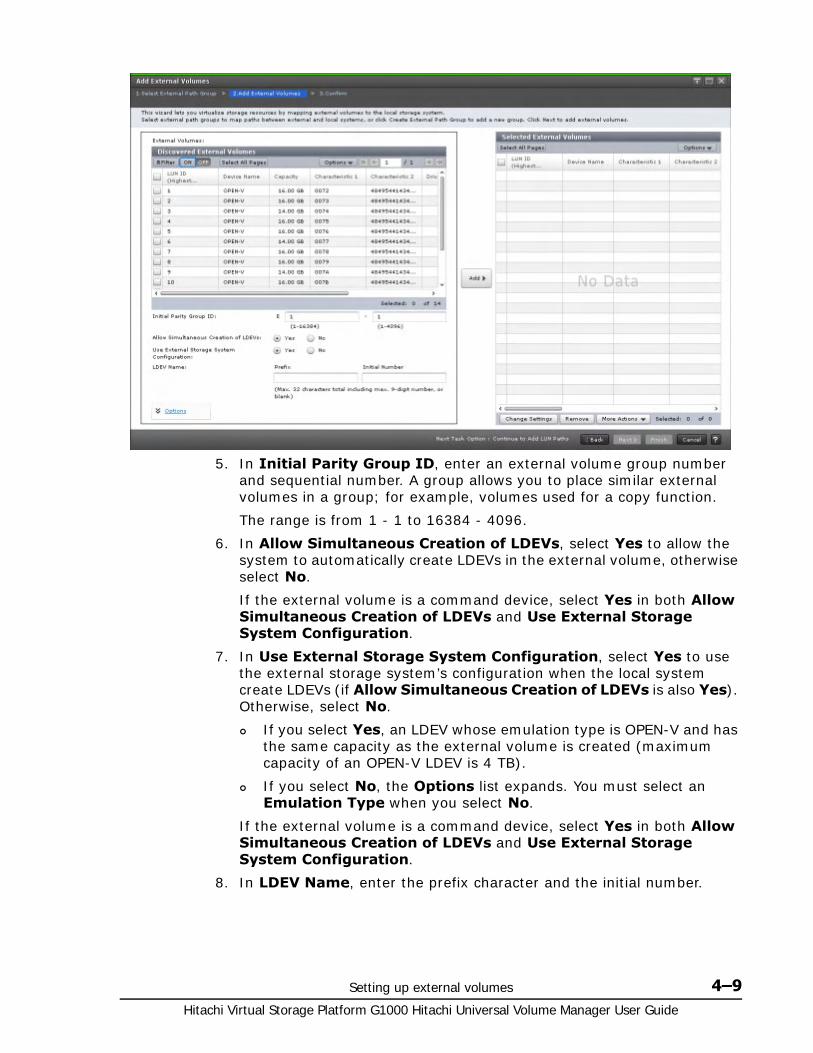
Setting up external volumes 4–9Hitachi Virtual Storage Platform G1000 Hitachi Universal Volume Manager User Guide
5. In Initial Parity Group ID, enter an external volume group number and sequential number. A group allows you to place similar external volumes in a group; for example, volumes used for a copy function.
The range is from 1 - 1 to 16384 - 4096.
6. In Allow Simultaneous Creation of LDEVs, select Yes to allow the system to automatically create LDEVs in the external volume, otherwise select No.
If the external volume is a command device, select Yes in both Allow Simultaneous Creation of LDEVs and Use External Storage System Configuration.
7. In Use External Storage System Configuration, select Yes to use the external storage system’s configuration when the local system create LDEVs (if Allow Simultaneous Creation of LDEVs is also Yes). Otherwise, select No.
If you select Yes, an LDEV whose emulation type is OPEN-V and has the same capacity as the external volume is created (maximum capacity of an OPEN-V LDEV is 4 TB).
If you select No, the Options list expands. You must select an Emulation Type when you select No.
If the external volume is a command device, select Yes in both Allow Simultaneous Creation of LDEVs and Use External Storage System Configuration.
8. In LDEV Name, enter the prefix character and the initial number.

Hitachi Virtual Storage Platform G1000 Hitachi Universal Volume Manager User Guide
4–10 Setting up external volumes
The entire value can be a maximum of 32 characters including the initial number (numerical value of 9 digits or less), or blank. Blank is displayed by default. Note the following numbering rule:
1:total 9 numbers (1,2,3,…9)
08:total 92 numbers (08,09,10,…99)
23:total 77 numbers (23,24,25,…99)
098:total 902 numbers (098,099,100…999)
9. Click Options (if not already expanded). If you have previously edited mapping settings (policies), you may not want to change the options. However, review the following steps—since some fields in Options are affected by preceding steps.
10.In the expanded Options box, for Initial LDEV ID enter the initial LDEV ID for the external volume. The local storage system searches from this number in ascending order and allocates the next available ID. You can review used, available, and disabled LDEVS by clicking View LDEV IDs.
For LDKC, enter 00.
For CU, enter the CU number, which can from 00 to FE. 00 is the default.
For DEV, enter the LDEV ID, which can be from 00 to FF. 00 is the default.
For Interval, enter an interval between LDEV IDs, which can be from 0 to 255. 0 is the default.
11.In Initial SSID, enter the SSID, which can be from 0004 to FFFE. 0004 is the default.
You can review the current SSIDs by clicking View SSIDs.

Setting up external volumes 4–11Hitachi Virtual Storage Platform G1000 Hitachi Universal Volume Manager User Guide
12.In Base Emulation Type, select the emulation type of the external volume.
If you selected Yes in Allow Simultaneous Creation of LDEVs and No in Use External Storage System Configuration, you must select an emulation type. If you selected Yes in both fields, Base Emulation Type is greyed out, and OPEN-V is automatically set.
13.In Number of LDEVs per External Volume, enter the number of LDEVs to be created when the volume is mapped. This field is greyed out if you selected Yes in Allow Simultaneous Creation of LDEVs and Use External Storage System Configuration, and 1 displays (since OPEN-V is the emulation type). See Capacity requirements for volumes on page 2-9 for more information.
14.In Cache Partition, select the CLPR for accessing the mapped external volume.
15.In Cache Mode, click Enable to propagate write data asynchronously from cache to the external storage system. Click Disable to propagate data synchronously.
If you specify Disable, the Cache Residency Manager bind mode cannot be set.
When the external volume is a command device, Cache Mode for the remote command device is automatically set to Disable regardless of your setting.
Data that is not written by the host (for example, data written by pair operation) is asynchronously destaged to the external storage system regardless of the Cache Mode setting.
16.In Inflow Control, click Enable to limit or prevent write data from being written to cache memory when the write operation to the external volume cannot be performed. Click Disable to allow write data to be written to cache.
17.In MP Blade, select the MP blade for the external volume. MP blade assignment should evenly distribute work across the available processors.
The range is from MPB0 to MPB7. The value depends on the configuration of the device.
Select Auto (the default) to cause an MP blade to be automatically assigned by the system. If Auto cannot be selected, the MP blade with the lowest number is selected by default.
18.Click Add.
19.If you need to change the added volume’s settings, in the Selected External Volumes list click the volume, click Change Settings, make necessary changes, and click OK.
20.To to add LUN paths, click Next in the Add External Volumes window. See the Hitachi Virtual Storage Platform G1000 Provisioning Guide for Open Systems for information.
Note: For more information about the Cache Partition, Cache Mode, and Inflow Control settings, see Editing external volume policies (settings) on page 5-2.

Hitachi Virtual Storage Platform G1000 Hitachi Universal Volume Manager User Guide
4–12 Setting up external volumes
21.Click Finish when ready.
22.In the Confirm window, check all settings, and then accept the task name or enter a one.
When you select the external volume and click LDEV Detail, the External LDEV Properties window is displayed for you to check the LDEV information.
23.In the Confirm window, click Apply.
Related Topics• Add External Volumes wizard on page D-17
• Create External Path Group window on page D-46
• Change Settings window on page D-48
• View External LUN Properties window on page D-50
• External LDEV Properties window on page D-57
• Discovery Result Detail window on page D-58
• Table B-1 Restrictions on remote command device on page B-3
• View SSIDs in the Hitachi Virtual Storage Platform G1000 Provisioning Guide for Open Systems or the Hitachi Virtual Storage Platform G1000 Provisioning Guide for Mainframe Systems
• Edit SSIDs in the Hitachi Virtual Storage Platform G1000 Provisioning Guide for Open Systems or the Hitachi Virtual Storage Platform G1000 Provisioning Guide for Mainframe Systems
Preparing mapped volumes for use After external volumes are mapped to the local storage system, you can take the following steps to prepare the volumes for use.
Required Role
• Storage Administrator (Provisioning)
1. Based on emulation type, perform one of the following:
For mainframe emulation, the status of the mapped volume becomes Blockade after mapping. Format the volume using Virtual LVI to change to a normal status.
For zero-formatted external volumes, use Virtual LVI to perform the Write to Control Blocks operation to restore the volume. Even if you formatted the volume from the external storage side after recovering the mapped volume, you must perform the Write to Control Blocks operation of the VLL feature after the formatting. For instructions, see the Hitachi Virtual Storage Platform G1000 Provisioning Guide for Mainframe Systems.
For open-system emulation, the status of the mapped volume automatically becomes Normal. If you need to initialize the data area of the mapped volume, format the volume using Virtual LUN.
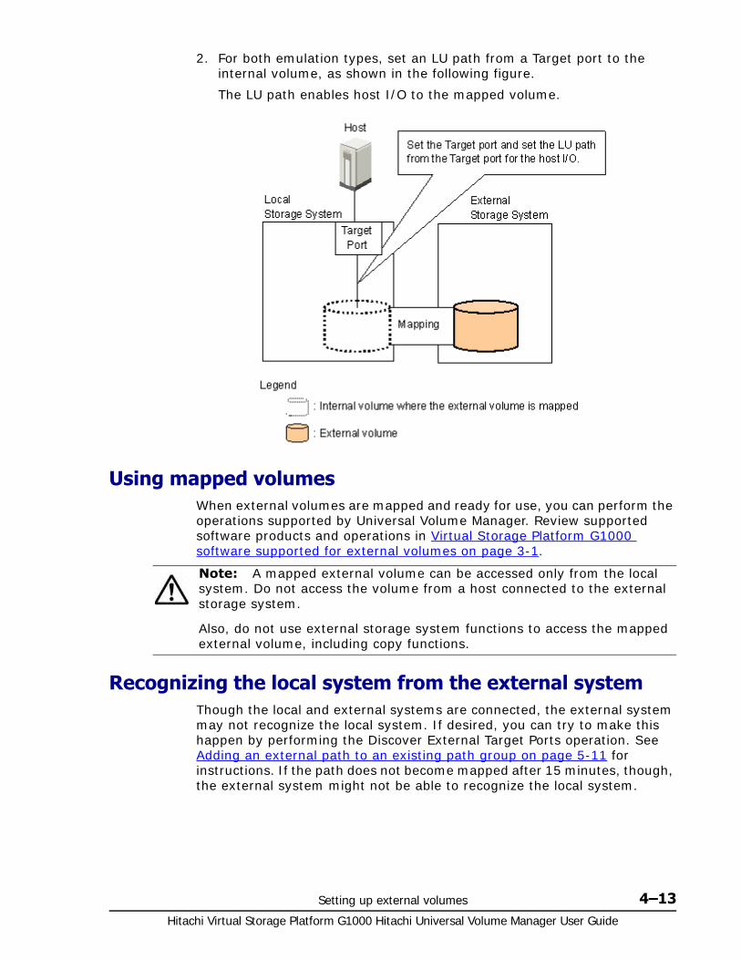
Setting up external volumes 4–13Hitachi Virtual Storage Platform G1000 Hitachi Universal Volume Manager User Guide
2. For both emulation types, set an LU path from a Target port to the internal volume, as shown in the following figure.
The LU path enables host I/O to the mapped volume.
Using mapped volumes When external volumes are mapped and ready for use, you can perform the operations supported by Universal Volume Manager. Review supported software products and operations in Virtual Storage Platform G1000 software supported for external volumes on page 3-1.
Recognizing the local system from the external systemThough the local and external systems are connected, the external system may not recognize the local system. If desired, you can try to make this happen by performing the Discover External Target Ports operation. See Adding an external path to an existing path group on page 5-11 for instructions. If the path does not become mapped after 15 minutes, though, the external system might not be able to recognize the local system.
Note: A mapped external volume can be accessed only from the local system. Do not access the volume from a host connected to the external storage system.
Also, do not use external storage system functions to access the mapped external volume, including copy functions.

Hitachi Virtual Storage Platform G1000 Hitachi Universal Volume Manager User Guide
4–14 Setting up external volumes
5
Monitoring and maintenance 5–1Hitachi Virtual Storage Platform G1000 Hitachi Universal Volume Manager User Guide
Monitoring and maintenance
This topic provides monitoring, editing, and maintenance instructions for external volumes, paths, and systems.
□ Monitoring external volumes and paths
□ Editing external volume policies (settings)
□ Changing MP blade for external volume
□ Changing path mode to ALUA mode (Enable or Disable)
□ Changing I/O system for external storage systems
□ Editing external WWN settings
□ Path maintenance
□ Disconnecting external systems and volumes
□ Reconnecting external systems and volumes
□ Deleting an external volume mapping
□ Powering off and on local, external storage systems
Hitachi Virtual Storage Platform G1000 Hitachi Universal Volume Manager User Guide
5–2 Monitoring and maintenance
Monitoring external volumes and paths You can view system details about mapped external volumes, the ports used, and the external paths.
Required Role
• Storage Administrator (Provisioning)
1. Open the External Storage window.
In the Hitachi Command Suite:a. On the Resources tab, click Storage Systems, and then expand
All Storage Systems.b. Expand the target storage systems, right-click External Storage,
and then select System GUI.
In Device Manager - Storage Navigator (mainframe only environment) a. Click Storage Systems, and then expand the Storage Systems
tree.b. Click External Storage.
2. On the External Storage Systems tab, click the link for an external system.
3. On the External Path Groups tab, click the link for a path group.
4. On the Mapped Volumes tab, select one or more external volumes, and then select View External LUN Properties.
Related Topics• View External LUN Properties window on page D-50
Editing external volume policies (settings)When you map new external volumes, preset mapping policies are used. You can change default mapping values without affecting settings in previously mapped volumes.
To reset the values for previously mapped volumes, go to the Edit External Volumes window and change settings volume by volume.
The settings and their functions are described in the following bullets. To skip to the procedure, see Editing mapping policies on page 5-4.
• Base Emulation Type
Specify OPEN-V to use existing data in the external volume from VSP G1000.
If you use an emulation type other than OPEN-V, the volume requires a specific area for management data. This results in a volume capacity after mapping that is less than the actual external volume capacity.
See Capacity requirements for volumes on page 2-9 for more information about capacity and calculating the capacity of your external volume.

Monitoring and maintenance 5–3Hitachi Virtual Storage Platform G1000 Hitachi Universal Volume Manager User Guide
• Cache Mode. I/O to and from the local storage system always uses cache. Write operations are always backed up in duplex cache. The Cache Mode setting specifies whether write data from the host is written to the external volume asynchronously (Enable) or synchronously (Disable).
If Enable is specified: After receiving the data into the local system’s cache memory, the system signals the host that the I/O operation has completed and then asynchronously destages the data to the external volume.
When Disable is specified (the default): After synchronously writing the data to the external volume, the local system signals the host that an I/O operation has completed.
For further discussion, see Cache use and external storage performance on page 2-6.
• Cache Partition. Cache memory can be partitioned using Virtual Partition Manager to configure a cache logical partition (CLPR) for the mapped volumes. Cache logical partitions are often used to limit cache-use by accessing slower external storage volumes.
Hitachi strongly recommends that you place external storage array groups in a CLPR other than CLPR0. See the Hitachi Virtual Partition Manager User Guide for detailed information on CLPR.
• Inflow Control. When the write operation to the external volume cannot be completed, Inflow Control specifies whether the write operation to cache memory is limited (Enable) or continued (Disable).
If Enable is specified, the write operation to cache is limited and I/O from the host is not accepted. Limiting the write operation prevents the accumulation of data that cannot destage to cache memory.
When Disable (the default) is specified, I/O from the host during the retry operation is written to cache memory. When write operations to the external volume are again possible, data in cache memory is written to the external volume (all data is destaged).
• ALUA mode (Use ALUA as Path Mode:Enable or Disable).
In the local storage system, you can select whether ALUA mode is used as the path mode. If ALUA is supported in the profile information of the external storage, Enable is used by default. Otherwise, Disable is used. For information on ALUA mode, see Supported external systems path mode for external volumes on page 2-17.
• Load Balance Mode. Select Depend on the selected external volume(s), Normal Round-robin, Extended Round-robin, or Disable as a Load Balance Mode for the external storage system. By default, Normal Round-robin is used. However, when the product name of the storage system is displayed as “generic”, Depend on the selected external volume(s) is used by default..
If Single is set as the Path Mode or Disable is set for Use ALUA as Path Mode, Load Balance Mode cannot be specified.

Hitachi Virtual Storage Platform G1000 Hitachi Universal Volume Manager User Guide
5–4 Monitoring and maintenance
Depend on the selected external volume(s): If Enable is set for ALUA Settable on the external volume, Normal Round-robin is set for Load Balance Mode automatically. If Disable is set for ALUA Settable, Disable is set for Load Balance Mode automatically.
Normal Round-robin: I/O is distributed to several paths on which I/O operation is enabled for the external storage system.
Extended Round-robin: I/O is distributed to several paths on which I/O operation is enabled for the external storage system. For sequential I/O, the external volume is divided into sections at regular intervals. In this case, the same path is used for I/O within the same section which reduces the frequency of I/O distribution.
Disable: As in Single mode, I/O operation is performed using the path that has the highest priority of all paths on which I/O operation is enabled for the external storage system.
Editing mapping policies Required Role
• Storage Administrator (Provisioning)
1. Open the External Storage window.
In the Hitachi Command Suite:a. On the Resources tab, click Storage Systems, and then expand
All Storage Systems.b. Expand the target storage systems, right-click External Storage,
and then select System GUI.
In Device Manager - Storage Navigator (mainframe only environment) a. Click Storage Systems, and then expand the Storage Systems
tree.b. Click External Storage.
2. In the External Storage window, click the External Paths tab.
3. On the External Paths tab, select a path group.
4. Click More Actions and select Edit Policies.
5. In the Edit Policies window, make whatever changes are required to the external volume settings.
6. Click Apply.

Monitoring and maintenance 5–5Hitachi Virtual Storage Platform G1000 Hitachi Universal Volume Manager User Guide
Related Topics• Edit Policies window on page D-28
Changing MP blade for external volumeRequired Role
• Storage Administrator (Provisioning)
1. Open the External Storage window.
In the Hitachi Command Suite:a. On the Resources tab, click Storage Systems, and then expand
All Storage Systems.b. Expand the target storage systems, right-click External Storage,
and then select System GUI.
In Device Manager - Storage Navigator (mainframe only environment) a. Click Storage Systems, and then expand the Storage Systems
tree.b. Click External Storage.
Note: You can also edit Cache Mode and Inflow Control for individual external volumes. In Device Manager - Storage Navigator, select an external volume in the Mapped Volumes tab. Then click Edit External Volumes.

Hitachi Virtual Storage Platform G1000 Hitachi Universal Volume Manager User Guide
5–6 Monitoring and maintenance
2. On the External Storage Systems tab, click the link for an external system.
3. On the External Path Groups tab, click the link for a path group.
4. On the Mapped Volumes tab, select one or more external volumes, and then select More Actions > Assign MP Blade.
5. In the Assign MP Blade window, select the desired MP blade.
The current setting for the external volume displays, unless you have selected multiple external volumes with different values. Then the field is blank.
The choices you see are dependent on the configuration of the device. They range from MPB0 to MPB7.
Selecting Auto allows the system to assign the blade.
6. Click Finish.
7. In the Confirm window, check the settings, accept the task name or enter a new one, and then click Apply.
Note: MP blade assignment should be set to evenly distribute work across all the available processors.
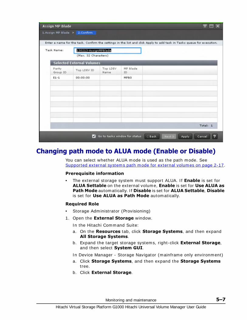
Monitoring and maintenance 5–7Hitachi Virtual Storage Platform G1000 Hitachi Universal Volume Manager User Guide
Changing path mode to ALUA mode (Enable or Disable)You can select whether ALUA mode is used as the path mode. See Supported external systems path mode for external volumes on page 2-17.
Prerequisite information
• The external storage system must support ALUA. If Enable is set for ALUA Settable on the external volume, Enable is set for Use ALUA as Path Mode automatically. If Disable is set for ALUA Settable, Disable is set for Use ALUA as Path Mode automatically.
Required Role
• Storage Administrator (Provisioning)
1. Open the External Storage window.
In the Hitachi Command Suite:a. On the Resources tab, click Storage Systems, and then expand
All Storage Systems.b. Expand the target storage systems, right-click External Storage,
and then select System GUI.
In Device Manager - Storage Navigator (mainframe only environment) a. Click Storage Systems, and then expand the Storage Systems
tree.b. Click External Storage.

Hitachi Virtual Storage Platform G1000 Hitachi Universal Volume Manager User Guide
5–8 Monitoring and maintenance
2. On the External Storage Systems tab, click the link for an external system.
3. On the External Path Groups tab, click the link for a path group.
4. On the Mapped Volumes tab, select an external volume, and then click Edit External Volumes.
5. On the Edit External Volumes window, select Enable or Disable as the Use ALUA as Path Mode property.
6. Click Finish to display the Confirm window.
7. Confirm the settings and enter the task name in the Task Name box.
8. In the Confirm window, click Apply.
Changing I/O system for external storage systemsWith Load Balance Mode settings, you can change the I/O system for external storage systems for each of the external volumes.
This section describes operations to change the Load Balance Mode of external volumes in the Edit External Volumes window. For more information, see Load Balance Mode on page 2-18.
Required Role
• Storage Administrator (Provisioning)
1. Open the External Storage window.
In the Hitachi Command Suite:a. On the Resources tab, click Storage Systems, and then expand
All Storage Systems.b. Expand the target storage systems, right-click External Storage,
and then select System GUI.
In Device Manager - Storage Navigator (mainframe only environment) a. Click Storage Systems, and then expand the Storage Systems
tree.b. Click External Storage.
2. On the External Storage Systems tab, click the link for an external system.
3. On the External Path Groups tab, click the link for a path group.
4. On the Mapped Volumes tab, select an external volume, and then click Edit External Volumes.
5. On the Edit External Volumes window, select the Load Balance Mode property, and then click Extended Round-robin, Normal Round-robin, or Disable.
6. Click Finish to display the Confirm window.
7. Confirm the settings and enter the task name in the Task Name box.
8. In the Confirm window, click Apply.

Monitoring and maintenance 5–9Hitachi Virtual Storage Platform G1000 Hitachi Universal Volume Manager User Guide
Editing external WWN settings You can change the external system’s WWN port setting. However, note the following:
• If the current setting is error-free, it is best to continue using it.
• For an external volume with normal I/O, set I/O Timeout from 5 - 15 seconds.
• Use the external system’s recommended values for other port settings.
Required Role
• Storage Administrator (Provisioning)
1. Open the External Storage window.
In the Hitachi Command Suite:a. On the Resources tab, click Storage Systems, and then expand
All Storage Systems.b. Expand the target storage systems, right-click External Storage,
and then select System GUI.
In Device Manager - Storage Navigator (mainframe only environment) a. Click Storage Systems, and then expand the Storage Systems
tree.b. Click External Storage.
2. Click the External Paths tab.
3. On the External Paths tab, select Edit External WWNs.

Hitachi Virtual Storage Platform G1000 Hitachi Universal Volume Manager User Guide
5–10 Monitoring and maintenance
4. In the Edit External WWNs window, change the desired settings.
Note: The current values for the external WWN display unless you have selected multiple paths with different values. Then the fields are blank.
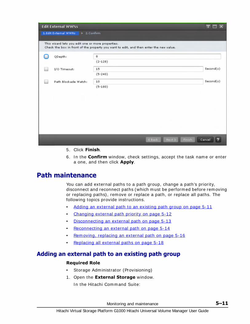
Monitoring and maintenance 5–11Hitachi Virtual Storage Platform G1000 Hitachi Universal Volume Manager User Guide
5. Click Finish.
6. In the Confirm window, check settings, accept the task name or enter a one, and then click Apply.
Path maintenanceYou can add external paths to a path group, change a path’s priority, disconnect and reconnect paths (which must be performed before removing or replacing paths), remove or replace a path, or replace all paths. The following topics provide instructions.
• Adding an external path to an existing path group on page 5-11
• Changing external path priority on page 5-12
• Disconnecting an external path on page 5-13
• Reconnecting an external path on page 5-14
• Removing, replacing an external path on page 5-16
• Replacing all external paths on page 5-18
Adding an external path to an existing path group Required Role
• Storage Administrator (Provisioning)
1. Open the External Storage window.
In the Hitachi Command Suite:

Hitachi Virtual Storage Platform G1000 Hitachi Universal Volume Manager User Guide
5–12 Monitoring and maintenance
a. On the Resources tab, click Storage Systems, and then expand All Storage Systems.
b. Expand the target storage systems, right-click External Storage, and then select System GUI.
In Device Manager - Storage Navigator (mainframe only environment) a. Click Storage Systems, and then expand the Storage Systems
tree.b. Click External Storage.
2. On the External Storage Systems tab, click the link for an external system.
3. On the External Path Groups tab, select a path group.
4. Click Edit External Path Configuration.
5. In the Edit External Path Configuration window, select an external path or paths from the Available External Paths list and click Add.
If the External Storage System or the External WWN that you want is not available in the dialog box, click Discover External Target Ports and add the port that connects to the WWN.
6. To change the priority of external paths, click Raise Priority or Lower Priority in the Selected External Paths list.
7. Click Finish.
8. In the Confirm window, check settings, accept the task name or enter a new one, and then click Apply.
Related Topics• Edit External Path Configuration wizard on page D-34
• Discover External Target Ports window on page D-45
Changing external path priority You can change the priority of your primary and alternate external paths, moving them higher or lower depending on your requirements. See External paths on page 2-14 for more information on path priorities for Single and Multi mode.
Required Role
• Storage Administrator (Provisioning)
1. Open the External Storage window.
In the Hitachi Command Suite:a. On the Resources tab, click Storage Systems, and then expand
All Storage Systems.b. Expand the target storage systems, right-click External Storage,
and then select System GUI.
In Device Manager - Storage Navigator (mainframe only environment) a. Click Storage Systems, and then expand the Storage Systems
tree.
Monitoring and maintenance 5–13Hitachi Virtual Storage Platform G1000 Hitachi Universal Volume Manager User Guide
b. Click External Storage.
2. On the External Storage Systems tab, click the link for an external system.
3. On the External Path Groups tab, select a path group.
4. Click Edit External Path Configuration.
5. In the Edit External Path Configuration window, in the Selected External Paths list, select the desired path and click Raise Priority or Lower Priority.
6. Repeat the previous step to continue moving the path higher or lower. Move other paths as needed.
7. Click Finish.
8. In the Confirm window, check settings, accept the new task name or enter a new one, and then click Apply.
Related Topics• Edit External Path Configuration wizard on page D-34
Disconnecting an external path You can disconnect all external paths connected either to a port on the local system or to a WWN on the external system. Disconnecting paths affects the external volumes mapped using the port.
An external path is disconnected for the following reasons:
• Before removing a path.
• To replace a path or switch
• To perform maintenance on a path
• To perform maintenance on the external system or volume
Prerequisite information
• When you disconnect a path, make certain that alternate paths are available for mapped external volumes using the path.
Required Role
• Storage Administrator (Provisioning)
1. Open the External Storage window.
In the Hitachi Command Suite:a. On the Resources tab, click Storage Systems, and then expand
All Storage Systems.b. Expand the target storage systems, right-click External Storage,
and then select System GUI.
In Device Manager - Storage Navigator (mainframe only environment) a. Click Storage Systems, and then expand the Storage Systems
tree.b. Click External Storage.
2. Click the External Paths tab.

Hitachi Virtual Storage Platform G1000 Hitachi Universal Volume Manager User Guide
5–14 Monitoring and maintenance
3. On the External Paths tab, select a path group.
4. Click Disconnect External Paths.
5. In the Disconnect External Paths window, select one of the following (illustrated in the figure below):
By Ports to disconnect all external paths connected to the specified port in the local storage system.
By External WWNs to disconnect all external paths connected to the specified WWNs (ports) in the external storage system.
6. Click Finish.
7. In the Confirm window, check settings, accept or enter a new task name, and then click Apply.
Related Topics• Edit External Path Configuration wizard on page D-34
Reconnecting an external path You can reconnect an external path that was disconnected. You reconnect paths either to a port on the local system or to a WWN on the external system. When you reconnect, original path settings are resumed.
Prerequisite information
• Make sure the path is in a status that can be restored.
Required Role
• Storage Administrator (Provisioning)
1. Open the External Storage window.
In the Hitachi Command Suite:a. On the Resources tab, click Storage Systems, and then expand
All Storage Systems.b. Expand the target storage systems, right-click External Storage,
and then select System GUI.

Monitoring and maintenance 5–15Hitachi Virtual Storage Platform G1000 Hitachi Universal Volume Manager User Guide
In Device Manager - Storage Navigator (mainframe only environment) a. Click Storage Systems, and then expand the Storage Systems
tree.b. Click External Storage.
2. Click the External Paths tab.
3. On the External Paths tab, select a path group.
4. Click Reconnect External Paths.
5. In the Reconnect External Paths window, select one of the following:
By Ports to reconnect all external paths connected to the specified port in the local storage system.
By External WWNs to reconnect all external paths connected to the specified WWNs (ports) in the external storage system.
6. Click Finish.
7. In the Confirm window, check settings, accept the task name or enter a one, and then click Apply.
Related Topics• Reconnect External Paths wizard on page D-43
Changing the cache mode setting of the external volumeYou can change the cache mode of the external volume in the Edit External Volumes window.
Prerequisites
Before changing the cache mode of the external volume, check each item listed in the following table.
Changing the cache mode
If the system cannot communicate with external volumes, the Inflow Control setting specifies whether the write operation to cache is limited (Enable) or continued (Disable). Disable is set by default. You can change the setting in the Edit External Volumes window.
Required Role
Item to Check Description
Cache Residency Manager and cache mode
When the bind mode is set, you cannot change the cache mode from Enable to Disable. To change the cache mode to Disable, cancel the setting for Cache Residency Manager or change the cache residency mode to the priority mode.
Cache mode and pool volumes
When a volume is registered to a pool as a pool volume, the cache mode setting should be the same among all the pool volumes in the pool.
Cache mode and remote command devices
When the volume is a remote command device, you cannot change the cache mode from Disable to Enable.

Hitachi Virtual Storage Platform G1000 Hitachi Universal Volume Manager User Guide
5–16 Monitoring and maintenance
• Storage Administrator (Provisioning)
1. Open the External Storage window.
In the Hitachi Command Suite:a. On the Resources tab, click Storage Systems, and then expand
All Storage Systems.b. Expand the target storage systems, right-click External Storage,
and then select System GUI.
In Device Manager - Storage Navigator (mainframe only environment) a. Click Storage Systems, and then expand the Storage Systems
tree.b. Click External Storage.
2. On the External Storage Systems tab, click the link for an external storage system.
3. On the External Path Groups tab, click the link for a path group.
4. On the Mapped Volumes tab, select an external volume, and then click Edit External Volumes.
5. On the Edit External Volumes window, select the Inflow Control property, and then click Enable or Disable.
6. Click Finish to display the Confirm window.
7. Confirm the settings and enter the task name in the Task Name box.
8. In the Confirm window, click Apply.
Related Topics• Edit External Volumes wizard on page D-30
• Supported external systems path mode for external volumes on page 2-17
Removing, replacing an external path You can remove a path so it is no longer available to the external volume. You remove a path to replace it with another external path or to perform maintenance on the physical link.
Prerequisite information
• Before removing a path, make sure it is disconnected. See Disconnecting an external path on page 5-13 for instructions.
1. Open the External Storage window.
In the Hitachi Command Suite:a. On the Resources tab, click Storage Systems, and then expand
All Storage Systems.b. Expand the target storage systems, right-click External Storage,
and then select System GUI.
Note: All external paths must be removed before detaching a channel adaptor, otherwise the channel adaptor cannot be detached.

Monitoring and maintenance 5–17Hitachi Virtual Storage Platform G1000 Hitachi Universal Volume Manager User Guide
In Device Manager - Storage Navigator (mainframe only environment) a. Click Storage Systems, and then expand the Storage Systems
tree.b. Click External Storage.
2. On the External Storage Systems tab, click the link for an external system.
3. On the External Path Groups tab, select a path group.
4. Click Edit External Path Configuration.
5. In the Edit External Path Configuration window, in the Selected External Paths list, select the path to be removed and click Remove.
The external path is deleted from the Selected External Paths list.
6. Click Finish.
7. In the Confirm window, check settings, accept or enter a new task name, and then click Apply.
If you are replacing the path, see Adding an external path to an existing path group on page 5-11.
Related Topics• Edit External Path Configuration wizard on page D-34

Hitachi Virtual Storage Platform G1000 Hitachi Universal Volume Manager User Guide
5–18 Monitoring and maintenance
Replacing all external paths You can replace the primary and alternate paths used by an external volume. Doing this requires one path to remain in Normal status at all times, which is shown in the following figure.
This procedure uses the illustration above.
1. Disconnect external path A. See Disconnecting an external path on page 5-13.
2. Disconnect the cable for external path A, then remove it. See Removing, replacing an external path on page 5-16.
3. Make sure the cable for external path C is connected, and then add this path to an existing path group. See Adding an external path to an existing path group on page 5-11.
When external path C status is Normal, then both external path B and external path C are set, and you can replace the next path.
4. Disconnect external path B.
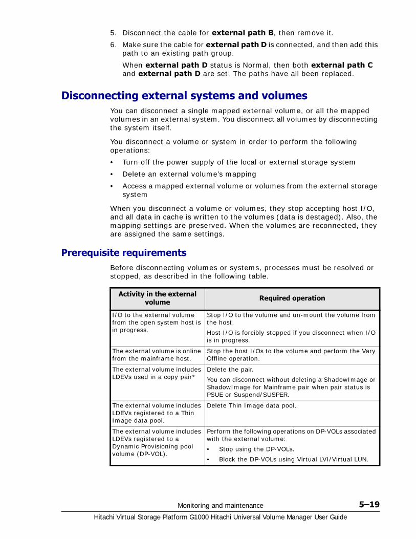
Monitoring and maintenance 5–19Hitachi Virtual Storage Platform G1000 Hitachi Universal Volume Manager User Guide
5. Disconnect the cable for external path B, then remove it.
6. Make sure the cable for external path D is connected, and then add this path to an existing path group.
When external path D status is Normal, then both external path C and external path D are set. The paths have all been replaced.
Disconnecting external systems and volumes You can disconnect a single mapped external volume, or all the mapped volumes in an external system. You disconnect all volumes by disconnecting the system itself.
You disconnect a volume or system in order to perform the following operations:
• Turn off the power supply of the local or external storage system
• Delete an external volume’s mapping
• Access a mapped external volume or volumes from the external storage system
When you disconnect a volume or volumes, they stop accepting host I/O, and all data in cache is written to the volumes (data is destaged). Also, the mapping settings are preserved. When the volumes are reconnected, they are assigned the same settings.
Prerequisite requirementsBefore disconnecting volumes or systems, processes must be resolved or stopped, as described in the following table.
Activity in the external volume Required operation
I/O to the external volume from the open system host is in progress.
Stop I/O to the volume and un-mount the volume from the host.
Host I/O is forcibly stopped if you disconnect when I/O is in progress.
The external volume is online from the mainframe host.
Stop the host I/Os to the volume and perform the Vary Offline operation.
The external volume includes LDEVs used in a copy pair*
Delete the pair.
You can disconnect without deleting a ShadowImage or ShadowImage for Mainframe pair when pair status is PSUE or Suspend/SUSPER.
The external volume includes LDEVs registered to a Thin Image data pool.
Delete Thin Image data pool.
The external volume includes LDEVs registered to a Dynamic Provisioning pool volume (DP-VOL).
Perform the following operations on DP-VOLs associated with the external volume:
• Stop using the DP-VOLs.
• Block the DP-VOLs using Virtual LVI/Virtual LUN.

Hitachi Virtual Storage Platform G1000 Hitachi Universal Volume Manager User Guide
5–20 Monitoring and maintenance
Disconnecting an external storage system, all mapped volumes When you disconnect an external system, the mapped external volumes in the system are also disconnected. This is the primary method for disconnecting all the mapped volumes in an external system.
Before disconnecting a mapped volume, review Prerequisite requirements on page 5-19.
Required Role
• Storage Administrator (Provisioning)
1. Open the External Storage window.
In the Hitachi Command Suite:a. On the Resources tab, click Storage Systems, and then expand
All Storage Systems.b. Expand the target storage systems, right-click External Storage,
and then select System GUI.
In Device Manager - Storage Navigator (mainframe only environment) a. Click Storage Systems, and then expand the Storage Systems
tree.b. Click External Storage.
2. On the External Storage Systems tab, select a path group.
3. Click Disconnect External Storage Systems.
4. In the Disconnect External Storage Systems window, review the volumes that will be disconnected, then click Apply.
The external volume includes LDEVs for which Volume Migration processing is in progress.
Delete the migration plans.
The global-active device quorum disk is used.
Delete the quorum disk settings.
* Copy software products are: ShadowImage, ShadowImage for Mainframe, Universal Replicator, Universal Replicator for Mainframe, TrueCopy, TrueCopy for Mainframe, and Thin Image.
Activity in the external volume Required operation
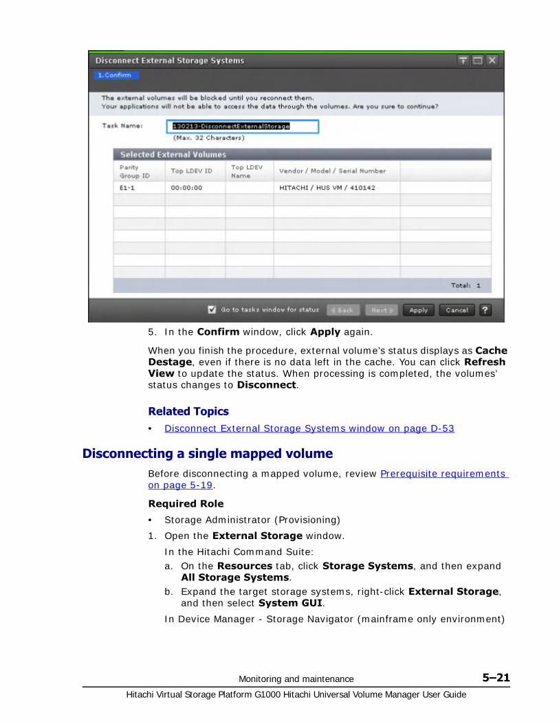
Monitoring and maintenance 5–21Hitachi Virtual Storage Platform G1000 Hitachi Universal Volume Manager User Guide
5. In the Confirm window, click Apply again.
When you finish the procedure, external volume’s status displays as Cache Destage, even if there is no data left in the cache. You can click Refresh View to update the status. When processing is completed, the volumes’ status changes to Disconnect.
Related Topics• Disconnect External Storage Systems window on page D-53
Disconnecting a single mapped volume Before disconnecting a mapped volume, review Prerequisite requirements on page 5-19.
Required Role
• Storage Administrator (Provisioning)
1. Open the External Storage window.
In the Hitachi Command Suite:a. On the Resources tab, click Storage Systems, and then expand
All Storage Systems.b. Expand the target storage systems, right-click External Storage,
and then select System GUI.
In Device Manager - Storage Navigator (mainframe only environment)
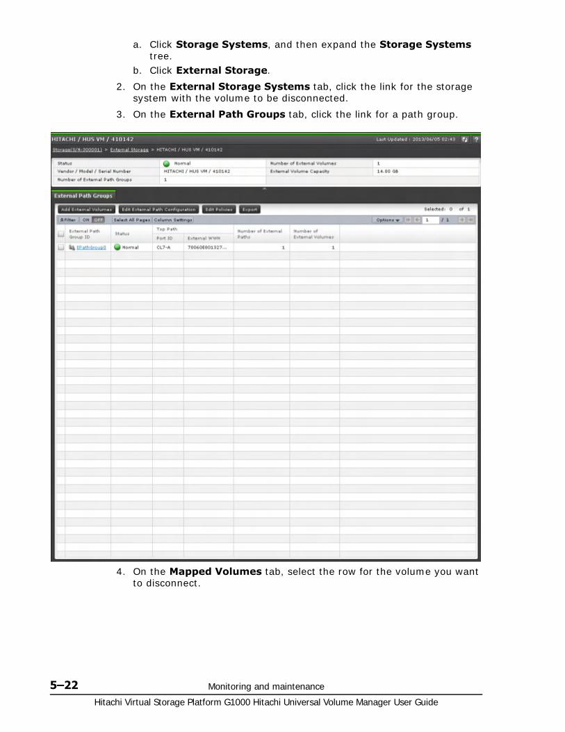
Hitachi Virtual Storage Platform G1000 Hitachi Universal Volume Manager User Guide
5–22 Monitoring and maintenance
a. Click Storage Systems, and then expand the Storage Systems tree.
b. Click External Storage.
2. On the External Storage Systems tab, click the link for the storage system with the volume to be disconnected.
3. On the External Path Groups tab, click the link for a path group.
4. On the Mapped Volumes tab, select the row for the volume you want to disconnect.

Monitoring and maintenance 5–23Hitachi Virtual Storage Platform G1000 Hitachi Universal Volume Manager User Guide
5. Click More Actions and select Disconnect External Volumes.
6. In the Disconnect External Volumes window, select the row of the volume to be disconnected, accept the task name or enter a new one, and then click Apply.

Hitachi Virtual Storage Platform G1000 Hitachi Universal Volume Manager User Guide
5–24 Monitoring and maintenance
7. Click Apply in the Confirm window.
When you finish the procedure, the external volume’s status displays as Cache Destage, even if there is no data left in the cache. You can click Refresh View to update the status. When processing is completed, the volumes’ status changes to Disconnect.
Related Topics• Disconnect External Volumes window on page D-54
Reconnecting external systems and volumes When you disconnect an external volume or volumes, you can start using them again by reconnecting.
When you reconnect a volume or system, the preserved mapping settings and path status are compared to the current status of the volume. When the status and settings match, the volume is again placed in mapped, Normal status and is available for I/O operations. However, if the external volume is not ready to be resumed, the status of the disconnected volume is Blockade. If this occurs, see General troubleshooting on page 6-2 and proceed as directed.
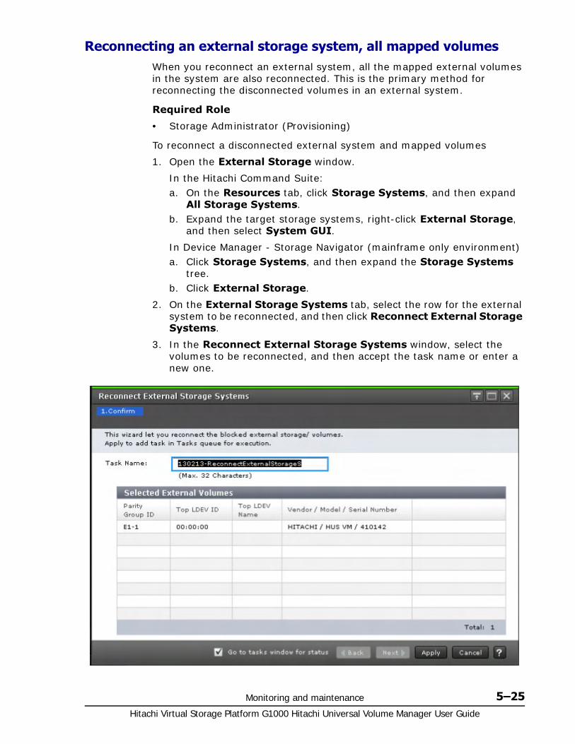
Monitoring and maintenance 5–25Hitachi Virtual Storage Platform G1000 Hitachi Universal Volume Manager User Guide
Reconnecting an external storage system, all mapped volumesWhen you reconnect an external system, all the mapped external volumes in the system are also reconnected. This is the primary method for reconnecting the disconnected volumes in an external system.
Required Role
• Storage Administrator (Provisioning)
To reconnect a disconnected external system and mapped volumes
1. Open the External Storage window.
In the Hitachi Command Suite:a. On the Resources tab, click Storage Systems, and then expand
All Storage Systems.b. Expand the target storage systems, right-click External Storage,
and then select System GUI.
In Device Manager - Storage Navigator (mainframe only environment) a. Click Storage Systems, and then expand the Storage Systems
tree.b. Click External Storage.
2. On the External Storage Systems tab, select the row for the external system to be reconnected, and then click Reconnect External Storage Systems.
3. In the Reconnect External Storage Systems window, select the volumes to be reconnected, and then accept the task name or enter a new one.
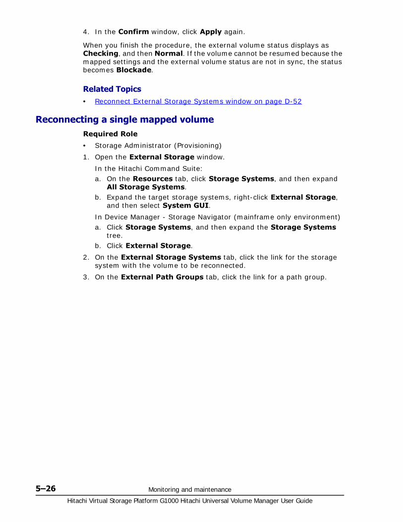
Hitachi Virtual Storage Platform G1000 Hitachi Universal Volume Manager User Guide
5–26 Monitoring and maintenance
4. In the Confirm window, click Apply again.
When you finish the procedure, the external volume status displays as Checking, and then Normal. If the volume cannot be resumed because the mapped settings and the external volume status are not in sync, the status becomes Blockade.
Related Topics• Reconnect External Storage Systems window on page D-52
Reconnecting a single mapped volume Required Role
• Storage Administrator (Provisioning)
1. Open the External Storage window.
In the Hitachi Command Suite:a. On the Resources tab, click Storage Systems, and then expand
All Storage Systems.b. Expand the target storage systems, right-click External Storage,
and then select System GUI.
In Device Manager - Storage Navigator (mainframe only environment) a. Click Storage Systems, and then expand the Storage Systems
tree.b. Click External Storage.
2. On the External Storage Systems tab, click the link for the storage system with the volume to be reconnected.
3. On the External Path Groups tab, click the link for a path group.
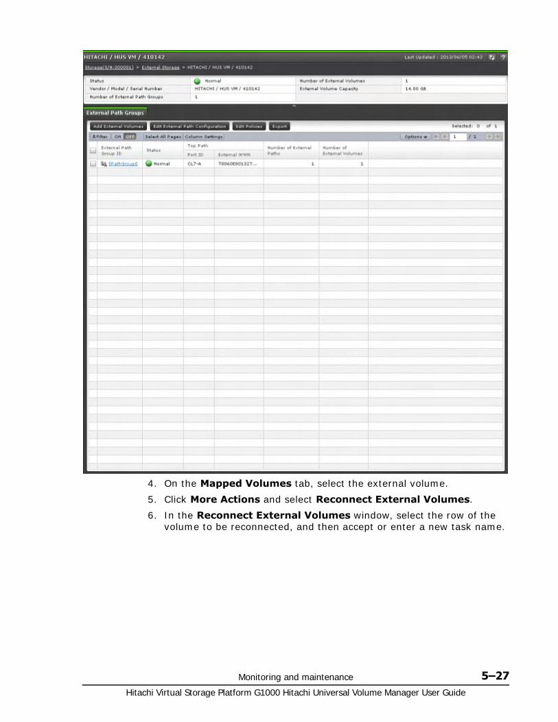
Monitoring and maintenance 5–27Hitachi Virtual Storage Platform G1000 Hitachi Universal Volume Manager User Guide
4. On the Mapped Volumes tab, select the external volume.
5. Click More Actions and select Reconnect External Volumes.
6. In the Reconnect External Volumes window, select the row of the volume to be reconnected, and then accept or enter a new task name.

Hitachi Virtual Storage Platform G1000 Hitachi Universal Volume Manager User Guide
5–28 Monitoring and maintenance
7. Click Apply in the Confirm window.
When you finish the procedure, the external volume status displays as Checking, and then Normal. If the volume cannot be resumed because the mapped settings and the external volume status are not in sync, the status becomes Blockade.
Related Topics• Reconnect External Volumes window on page D-53
Deleting an external volume mapping You can delete the mapping for an external volume. The data in the external volume is not deleted.
Prerequisite information
• The external volume or volumes to be deleted must first be disconnected, which results in all data in cache memory being written to the external volume.
However, you can delete a volume without disconnecting, meaning that data in cache is not destaged to the external volume.
• You cannot delete a mapping while the external volume is used in the following:
TrueCopy, Universal Replicator, ShadowImage, Thin Image, or global-active device.
Monitoring and maintenance 5–29Hitachi Virtual Storage Platform G1000 Hitachi Universal Volume Manager User Guide
A reserved volume for ShadowImage or Volume Migration.
A pool-VOL
A Quorum Disk
• For command devices, stop the application using the external volume as a command device.
Required Role
• Storage Administrator (Provisioning)
1. Open the External Storage window.
In the Hitachi Command Suite:a. On the Resources tab, click Storage Systems, and then expand
All Storage Systems.b. Expand the target storage systems, right-click External Storage,
and then select System GUI.
In Device Manager - Storage Navigator (mainframe only environment) a. Click Storage Systems, and then expand the Storage Systems
tree.b. Click External Storage.
2. On the External Storage Systems tab, click the link for an external system
3. On the External Path Groups tab, click the link for a path group.
4. On the Mapped Volumes tab, select the external volume.
5. Click More Actions and select Delete External Volumes.
6. In the Delete External Volumes window, verify the external volumes you want to delete.
Hitachi Virtual Storage Platform G1000 Hitachi Universal Volume Manager User Guide
5–30 Monitoring and maintenance
7. For Have you already disconnected external volume of above table?, click one of the following:
Yes if you have already disconnected the volumes.
No if you have not disconnected the volumes.
8. If you clicked No in the previous field, in the Do you want to execute Delete External Volumes operation without writing the cache data to the volumes?, click one of the following:
Yes to delete the external volumes without writing the data in cache memory into the volumes.
Cancel to disconnect the volume or volumes and then perform the delete operation again.
Note: When Yes is selected, the data remaining in cache is not guaranteed.

Monitoring and maintenance 5–31Hitachi Virtual Storage Platform G1000 Hitachi Universal Volume Manager User Guide
You cannot continue the operation if No is selected.
9. Click Finish.
10.In the Confirm window, check settings and accept the task name shown or enter a new one. When satisfied click Apply.
Related Topics• Delete External Volumes wizard on page D-39
Powering off and on local, external storage systems You must temporarily halt Universal Volume Manager functionality before powering off external storage systems. When the systems are powered on, you resume all functions.
The instructions in these topics should be closely followed.
• Prerequisite operations are required.
• A specific order must be followed:
When powering off both local and external systems, the local system must be turned off first, then the external system.
To power on both systems, the external system must be turned on first, then the local system.
Requirements for external storage system maintenanceYou must disconnect the external system and delete external volume mapping before making changes on the external system. When the changes are concluded, you reconnect the system and remap the external volume.
The following changes to the external system require the removal and remapping of the external volume:
• Changing WWNs of target ports that connect to the local storage system
• Changing the serial number of the external system
• Changing LUNs of volumes in the external system
• Reducing the volume capacity of the external volume
• Modification on the host connected directly to a external storage system.
If you want to change the WWNs of part of the target ports that are connected to the local storage system, you do not need to delete the volumes that are mapped to the local storage system.
To change the WWNs of the external storage system without deleting the external volume mapping
1. Change the WWN of the external storage.
See the Hitachi Virtual Storage Platform G1000 Provisioning Guide for Open Systems and the Hitachi Virtual Storage Platform G1000 Provisioning Guide for Mainframe Systems for detailed procedures. Changing the WWN blocks the external path that uses the target port with a WWN that has been changed.
Hitachi Virtual Storage Platform G1000 Hitachi Universal Volume Manager User Guide
5–32 Monitoring and maintenance
2. Add an external path between the local storage system and target port with a WWN that has been changed
3. Delete the external path that was blocked in step 1.
Before deleting external volume mapping, make sure that the volume has no LU paths and is not part of a copy pair. See Deleting an external volume mapping on page 5-28 for instructions.
Powering off and on the external storage systemRequired Role
• Storage Administrator (Provisioning)
To power off the external system
1. Stop read and write I/O to the mapped external volume.
2. If the external volume is defined as a DP-VOL in the internal system, block all DP-VOLs for maintenance as follows:
To block all DP-VOLs in the poola. Click Pools in the Storage Systems tree.b. In the tree, select the pool to be blocked.c. Select the Virtual Volumes tab.d. Click Select All Pages.e. On the menu bar, click Actions, Logical Device, and then Block
LDEVs. f. In the Block LDEVs window, confirm the settings and enter the task
name in the Task Name box.g. Click Apply in the Confirm window.
3. Disconnect the external storage system. See Disconnecting external systems and volumes on page 5-19 for instructions.
4. Perform the procedure for powering off the external storage system.
Related Topics• Block LDEVs window in the Hitachi Virtual Storage Platform G1000
Provisioning Guide for Open Systems
To power on the external system
1. Power on the external storage system.
2. Reconnect the external system. See Reconnecting external systems and volumes on page 5-24 for instructions.
3. If the external volume was defined as a DP-VOL in the local system, restore all blocked DP-VOLs.
To restore all DP-VOLs in the pool a. Click Pools in the Storage Systems tree.b. In the tree, select the pool to be restored.c. Select the Virtual Volumes tab.d. Click Select All Pages.
Monitoring and maintenance 5–33Hitachi Virtual Storage Platform G1000 Hitachi Universal Volume Manager User Guide
e. On the menu bar, click Actions, Logical Device, and then Restore LDEVs.
f. In the Restore LDEVs window, confirm the settings and enter the task name in the Task Name box.
g. Click Apply in the Confirm window.
Related Topics• Restore LDEVs window in the Hitachi Virtual Storage Platform G1000
Provisioning Guide for Open Systems
Powering off and on the local storage systemPrerequisite information
You do not need to disconnect the external system when powering off only the local system. However, if you do disconnect, when you power on the local system again, access is disabled to the external system until you reconnect.
To power off and on the local system
1. Stop read and write I/O to the local storage system.
2. Perform all necessary operations for powering off the local system.
Split pairs that use external volumes. For information on pairsplit operations, see the user guide for the relevant software.
3. Confirm that the status of each external volume is Normal or Disconnect.
4. Perform all necessary operations to power off the local system.
5. Turn off the power supply of the local storage system.
Data in local cache memory is written to the external volume when the local system is powered off (all data is destaged).
6. When you are ready, make sure that the external system is on and power on the local system.
Resync all pairs. For information on pairsync operations, see the user guide for the relevant software.
7. Start read or write I/O to the local storage system
Powering off and on both storage systemsTo power off both local and external storage systems
1. Stop read or write I/O to the local storage system.
2. Split all pairs using external volumes (pairsplit operation). For information on the pairsplit operation, see the user guide for the relevant software.
3. Confirm that the status of each external volume is Normal or Disconnect.
4. Power off the local storage system.
Hitachi Virtual Storage Platform G1000 Hitachi Universal Volume Manager User Guide
5–34 Monitoring and maintenance
5. When the power supply of the local system is completely off, power off the external system.
To power on both local and external storage systems
1. Power on the external system.
2. When the power supply of the external system is completely on, power on the local system.
3. Resume use of the mapped external volume.
4. Start read or write I/O to the local storage system.

6
Troubleshooting 6–1Hitachi Virtual Storage Platform G1000 Hitachi Universal Volume Manager User Guide
Troubleshooting
This topic provides troubleshooting information.
□ Contacting the Hitachi Data Systems Support Center
□ General troubleshooting
□ Troubleshooting external path status
□ Troubleshooting path errors for specific storage systems
□ Troubleshooting port and volume discovery problems
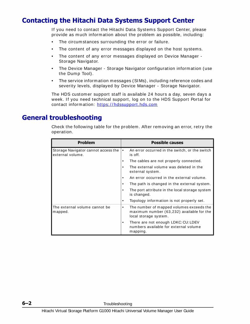
Hitachi Virtual Storage Platform G1000 Hitachi Universal Volume Manager User Guide
6–2 Troubleshooting
Contacting the Hitachi Data Systems Support CenterIf you need to contact the Hitachi Data Systems Support Center, please provide as much information about the problem as possible, including:
• The circumstances surrounding the error or failure.
• The content of any error messages displayed on the host systems.
• The content of any error messages displayed on Device Manager - Storage Navigator.
• The Device Manager - Storage Navigator configuration information (use the Dump Tool).
• The service information messages (SIMs), including reference codes and severity levels, displayed by Device Manager - Storage Navigator.
The HDS customer support staff is available 24 hours a day, seven days a week. If you need technical support, log on to the HDS Support Portal for contact information: https://hdssupport.hds.com
General troubleshooting Check the following table for the problem. After removing an error, retry the operation.
Problem Possible causes
Storage Navigator cannot access the external volume.
• An error occurred in the switch, or the switch is off.
• The cables are not properly connected.
• The external volume was deleted in the external system.
• An error occurred in the external volume.
• The path is changed in the external system.
• The port attribute in the local storage system is changed.
• Topology information is not properly set.
The external volume cannot be mapped.
• The number of mapped volumes exceeds the maximum number (63,232) available for the local storage system.
• There are not enough LDKC:CU:LDEV numbers available for external volume mapping.

Troubleshooting 6–3Hitachi Virtual Storage Platform G1000 Hitachi Universal Volume Manager User Guide
The external path is blocked. • See the problem above, “Device Manager - Storage Navigator cannot access the external volume”. If the problem persists after correcting any errors, continue to the next item.
• Confirm that the cable between the local and external system is connected properly.
• If the cable is properly connected, disconnect it and then reconnect. After 30 seconds, check the path status.
If the path is not restored, call the Hitachi Data Systems Support Center.
Action is required for a path status in the View External LUN Properties dialog box.
See Troubleshooting external path status on page 6-4.
The volume in the external system cannot be found even after port discovery or volume discovery was performed.
Perform any required action in the message and then retry the operation. If the problem persists, see Troubleshooting port and volume discovery problems on page 6-11.
The external volume is blocked. • All external paths are blocked (paths are not connected).
• The external volume is not set to Read/ Write.
• The external volume is blocked by an error.
The status of the external volume is blockade.
When errors occur in all external paths, the local storage system changes the status of the external volume to Blockade.
• Reconnect the volume or storage system.
• If the volume’s status still does not change to Normal, restore the path as described in the problem above, “The external path is blocked”, and then reconnect the volume again.
"?" displays in the LUN ID (Highest Priority) column of the Discovered External Volumes table (Add External Volumes window).
A corresponding external volume was not found for the external path with the highest priority.
Confirm the connection with the external system that failed during volume discovery, correct the error, and perform the operation again.
External volume discovery was not completed because of failure.
Confirm the connection with the external system; also confirm that the external volume is correctly configured in the external system, then perform the operation again.
After reconnecting an external volume or system, 10 minutes have passed but the status has not change from Checking.
Click Refresh on the Device Manager - Storage Navigator main window. If the status remains Checking, perform the reconnect operation again.
If the problem persists after a reasonable time, call the Hitachi Data Systems Support Center.
Problem Possible causes

Hitachi Virtual Storage Platform G1000 Hitachi Universal Volume Manager User Guide
6–4 Troubleshooting
Troubleshooting external path statusThe following table shows path statuses in the View External LUN Properties window. Descriptions and corrective actions you can take are provided.
Also, see Troubleshooting path errors for specific storage systems on page 6-6.
After disconnecting an external volume or system, the status does not change from Cache Destage.
Click Refresh on the Device Manager - Storage Navigator main window.
Note that the time required for write processing from cache to the external volume depends on volume capacity. More time is required for larger volumes. Processing speed is about 20 MB/s. However, this also depends on the performance and status of the external system.
If status does not change from Cache Destage after a reasonable time, call the Hitachi Data Systems Support Center.
The message, "INTERVENTION REQUIRED", is issued to the mainframe host as the device status.
The device status is currently changing. Wait a few minutes, and then check the status again. When the transition of the device status has completed normally, the device can be used immediately. If the device is blocked as a result of the status transition, see the problem above, "The external volume is blocked".
The message, “DEVICE ERROR", is issued to the mainframe host as the device status.
See the problem above, "The external volume is blocked"
Problem Possible causes
Status Description Corrective action
Unknown The path status cannot be determined.
Call the Hitachi Data Systems Support Center.
Blockade The external port is blocked. The port is blocked because of microcode replacement, package replacement, or other factor. Check the status of the local storage system. If you cannot restore the path, call the Hitachi Data Systems Support Center.
External device setting changed
An external system setting has changed. For example, the path definition was deleted, or the external system itself was replaced by another device.
The port of the external system is recognized. See your device manufacturer's documentation to verify that the settings on the volumes in question have not changed.
LDEV size reduced
The external volume capacity was reduced.
Check the external volume capacity. Delete the external volume, and then remap to it.
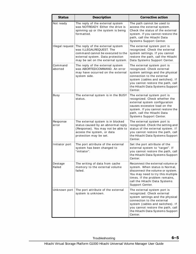
Troubleshooting 6–5Hitachi Virtual Storage Platform G1000 Hitachi Universal Volume Manager User Guide
Not ready The reply of the external system was NOTREADY. Either the drive is spinning up or the system is being formatted.
The path cannot be used to access the external system. Check the status of the external system. If you cannot restore the path, call the Hitachi Data Systems Support Center.
Illegal request The reply of the external system was ILLEGALREQUEST. The command cannot be executed to the external system. Data protection may be set on the external system.
The external system port is recognized. Check the external system settings. If you cannot restore the path, call the Hitachi Data Systems Support Center.
Command aborted
The reply of the external system was ABORTEDCOMMAND. An error may have occurred on the external system side.
The external system port is recognized. Check external system settings and the physical connection to the external system (cables and switches). If you cannot restore the path, call the Hitachi Data Systems Support Center.
Busy The external system is in the BUSY status.
The external system port is recognized. Check whether the external system configuration causes excessive load on the system. If you cannot restore the path, call the Hitachi Data Systems Support Center.
Response error
The external system is in blocked status caused by an abnormal reply (Response). You may not be able to access the system, or data protection may be set.
The external system port is recognized. Check the setting and status of the external system. If you cannot restore the path, call the Hitachi Data Systems Support Center.
Initiator port The port attribute of the external system has been changed to “initiator”.
Set the port attribute of the external system to “target”. If you cannot restore the path, call the Hitachi Data Systems Support Center.
Destage Failed
The writing of data from cache memory to the external volume failed.
Reconnect the external volume or system. When status is Normal, disconnect the volume or system. You may need to try this multiple times. If the problem remains, call the Hitachi Data Systems Support Center.
Unknown port The port attribute of the external system is unknown.
The external system port is recognized. Check external system settings and the physical connection to the external system (cables and switches). If you cannot restore the path, call the Hitachi Data Systems Support Center.
Status Description Corrective action

Hitachi Virtual Storage Platform G1000 Hitachi Universal Volume Manager User Guide
6–6 Troubleshooting
Troubleshooting path errors for specific storage systemsStorage system-specific recovery information is provided for the following errors:
• External device setting changed
• Illegal request
• Cannot detect port
Cannot detect port
The external path has been removed or the external system port cannot be found. Possible causes are:
• The fibre cable is not properly connected.
• The topology does not match between the external and target ports.
• Because security is set on the port, the external system cannot be recognized from the local system.
• If the external system is connected through switches, the switch setting may be incorrect.
If you cannot restore the path after checking the possible causes, call the Hitachi Data Systems Support Center.
Internal error A program error occurred, or there is a logical contradiction.
Call the Hitachi Data Systems Support Center.
Timeout Processing was retried because of an abnormal reply; however, processing was stopped because of timeout.
The external system port is recognized. Check external system settings and the physical connection to the external system (cables and switches). If you cannot restore the path, call the Hitachi Data Systems Support Center.
Device check error
An external volume is mapped, but you cannot access the volume in the external system.
Check the volume’s status in the external system and take any necessary corrective action.
Format the volume if it is not formatted.
Medium error The external volume has become inaccessible.
Check the volume’s status in the external system and take any necessary corrective action.
Format the volume if it is not formatted.
Status Description Corrective action

Troubleshooting 6–7Hitachi Virtual Storage Platform G1000 Hitachi Universal Volume Manager User Guide
VSP G1000 Storage System
Unified Storage VM, Virtual Storage Platform, and Universal Storage Platform V/VM
Path Status Description and corrective actions
External device setting changed
• LU path settings may have been changed by LUN Manager. Either change the settings back to the values used when the volume was mapped, or perform the Delete Volume and then Add Volume operations using Universal Volume Manager.
• The volume’s access attribute may have been changed by Data Retention Utility. If the volume is protected by the access attribute, release the protection.
Illegal request or
Response error
• If the volume is a pair volume, it may be protected because of the pair status. If this is the case, change the pair status or delete the pair. Make sure the volume is not set to a pair such as TrueCopy, Universal Replicator, ShadowImage, or global-active device.
• The volume’s access attribute may have been changed by Data Retention Utility. If the volume is protected by the access attribute, release the protection.
Cannot detect port
• There is a problem with connection to the external storage system. The possible causes are:
- Fibre cable connection. Make sure the fibre cable is connected correctly.
- Fiber Channel port settings. The setting of the topology may not match between the external port and the target port. Make sure that the Fibre Channel ports are set properly using LUN Manager.
- Switch settings. If the external storage system is connected through switches, make sure that the switch settings are correct.
• LUN security may have been enabled by LUN Manager. If so, disable it.
Path Status Description and corrective actions
External device setting changed
• LU path settings may have been changed by LUN Manager. Either change the settings back to the values used when the volume was mapped, or perform the Delete Volume and then Add Volume operations using Universal Volume Manager.
• The volume’s access attribute may have been changed by Data Retention Utility. If the volume is protected by the access attribute, release the protection.
Illegal request or
Response error
• If the volume is a pair volume, it may be protected because of the pair status. If this is the case, change the pair status or delete the pair.
• The volume’s access attribute may have been changed by Data Retention Utility. If the volume is protected by the access attribute, release the protection.

Hitachi Virtual Storage Platform G1000 Hitachi Universal Volume Manager User Guide
6–8 Troubleshooting
Universal Storage Platform / TagmaStore NSC
Cannot detect port
• There is a problem with connection to the external storage system. The possible causes are:
- Fibre cable connection. Make sure the fibre cable is connected correctly.
- Fiber Channel port settings. The setting of the topology may not match between the external port and the target port. Make sure that the Fibre Channel ports are set properly using LUN Manager.
- Switch settings. If the external storage system is connected through switches, make sure that the switch settings are correct.
• LUN security may have been enabled by LUN Manager. If so, disable it.
Path Status Description and corrective actions
External device setting changed
• LU path settings may have been changed by LUN Manager. Either change the settings back to the values used when the volume was mapped, or perform the Delete LU and then Add LU operations using Universal Volume Manager.
• The volume’s access attribute may have been changed by Data Retention Utility. If the volume is protected by the access attribute, release the protection.
Illegal request or
Response error
• If the volume is a pair volume, it may be protected because of the pair status. If this is the case, change the pair status or delete the pair.
• The volume’s access attribute may have been changed by Data Retention Utility. If the volume is protected by the access attribute, release the protection.
Cannot detect port
• There is a problem with connection to the external storage system. The possible causes are:
- Fibre cable connection. Make sure the fibre cable is connected correctly.
- Fiber Channel port settings. The setting of the topology may not match between the external port and the target port. Make sure that the Fibre Channel ports are set properly using LUN Manager.
- Switch settings. If the external storage system is connected through switches, make sure that the switch settings are correct.
• LUN security may have been enabled by LUN Manager. If so, disable it.
Path Status Description and corrective actions
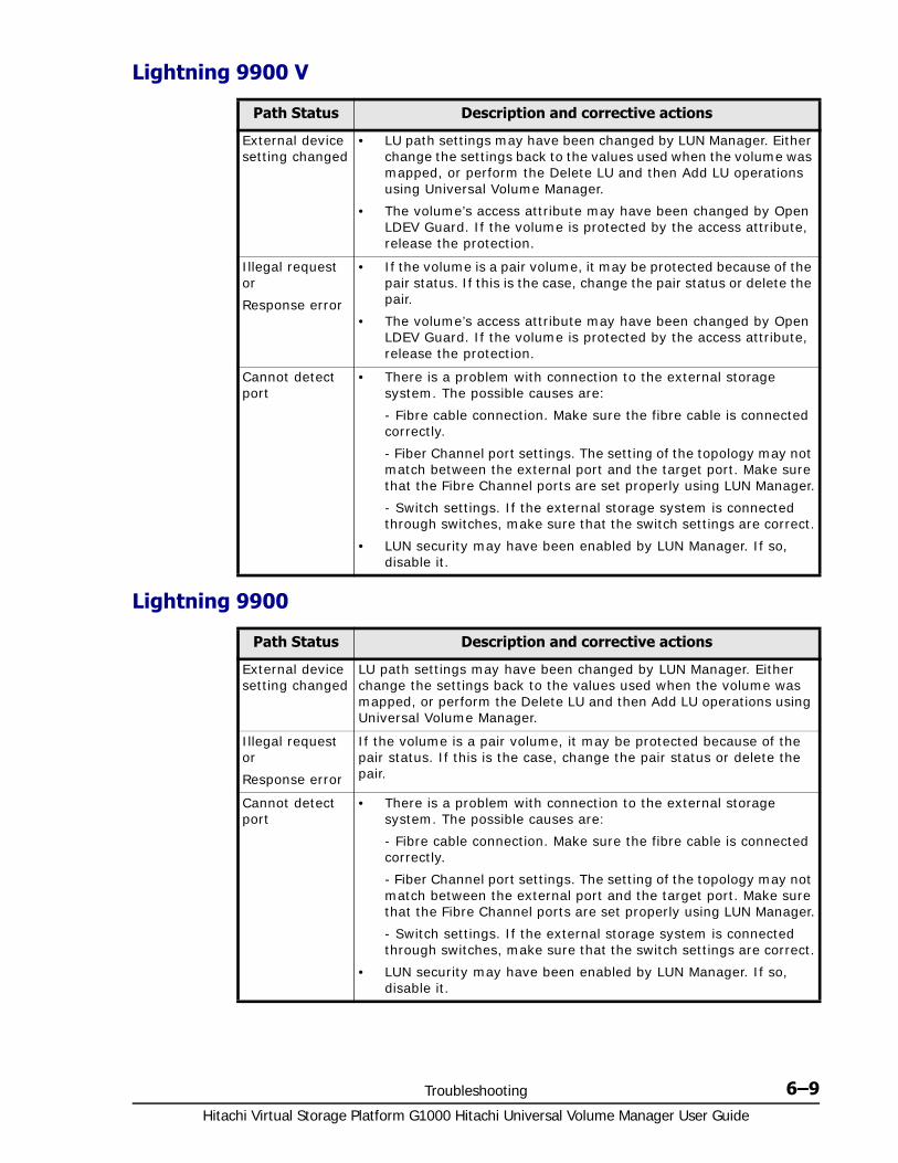
Troubleshooting 6–9Hitachi Virtual Storage Platform G1000 Hitachi Universal Volume Manager User Guide
Lightning 9900 V
Lightning 9900
Path Status Description and corrective actions
External device setting changed
• LU path settings may have been changed by LUN Manager. Either change the settings back to the values used when the volume was mapped, or perform the Delete LU and then Add LU operations using Universal Volume Manager.
• The volume’s access attribute may have been changed by Open LDEV Guard. If the volume is protected by the access attribute, release the protection.
Illegal request or
Response error
• If the volume is a pair volume, it may be protected because of the pair status. If this is the case, change the pair status or delete the pair.
• The volume’s access attribute may have been changed by Open LDEV Guard. If the volume is protected by the access attribute, release the protection.
Cannot detect port
• There is a problem with connection to the external storage system. The possible causes are:
- Fibre cable connection. Make sure the fibre cable is connected correctly.
- Fiber Channel port settings. The setting of the topology may not match between the external port and the target port. Make sure that the Fibre Channel ports are set properly using LUN Manager.
- Switch settings. If the external storage system is connected through switches, make sure that the switch settings are correct.
• LUN security may have been enabled by LUN Manager. If so, disable it.
Path Status Description and corrective actions
External device setting changed
LU path settings may have been changed by LUN Manager. Either change the settings back to the values used when the volume was mapped, or perform the Delete LU and then Add LU operations using Universal Volume Manager.
Illegal request or
Response error
If the volume is a pair volume, it may be protected because of the pair status. If this is the case, change the pair status or delete the pair.
Cannot detect port
• There is a problem with connection to the external storage system. The possible causes are:
- Fibre cable connection. Make sure the fibre cable is connected correctly.
- Fiber Channel port settings. The setting of the topology may not match between the external port and the target port. Make sure that the Fibre Channel ports are set properly using LUN Manager.
- Switch settings. If the external storage system is connected through switches, make sure that the switch settings are correct.
• LUN security may have been enabled by LUN Manager. If so, disable it.
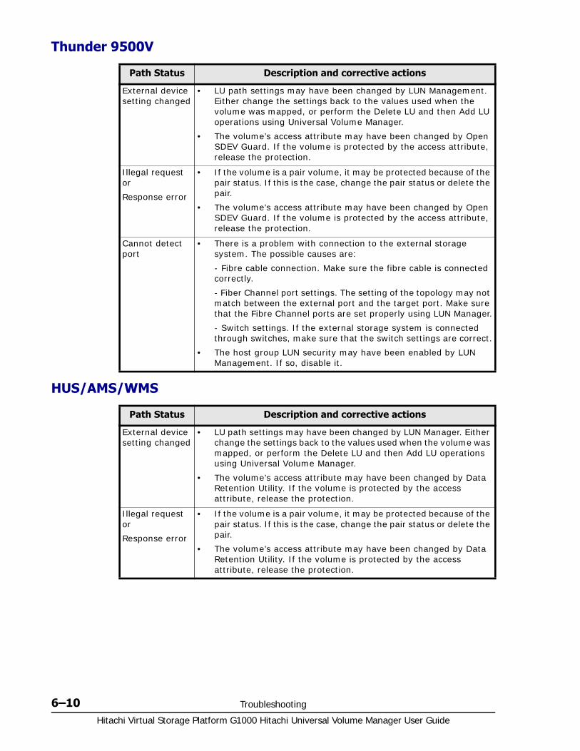
Hitachi Virtual Storage Platform G1000 Hitachi Universal Volume Manager User Guide
6–10 Troubleshooting
Thunder 9500V
HUS/AMS/WMS
Path Status Description and corrective actions
External device setting changed
• LU path settings may have been changed by LUN Management. Either change the settings back to the values used when the volume was mapped, or perform the Delete LU and then Add LU operations using Universal Volume Manager.
• The volume’s access attribute may have been changed by Open SDEV Guard. If the volume is protected by the access attribute, release the protection.
Illegal request or
Response error
• If the volume is a pair volume, it may be protected because of the pair status. If this is the case, change the pair status or delete the pair.
• The volume’s access attribute may have been changed by Open SDEV Guard. If the volume is protected by the access attribute, release the protection.
Cannot detect port
• There is a problem with connection to the external storage system. The possible causes are:
- Fibre cable connection. Make sure the fibre cable is connected correctly.
- Fiber Channel port settings. The setting of the topology may not match between the external port and the target port. Make sure that the Fibre Channel ports are set properly using LUN Manager.
- Switch settings. If the external storage system is connected through switches, make sure that the switch settings are correct.
• The host group LUN security may have been enabled by LUN Management. If so, disable it.
Path Status Description and corrective actions
External device setting changed
• LU path settings may have been changed by LUN Manager. Either change the settings back to the values used when the volume was mapped, or perform the Delete LU and then Add LU operations using Universal Volume Manager.
• The volume’s access attribute may have been changed by Data Retention Utility. If the volume is protected by the access attribute, release the protection.
Illegal request or
Response error
• If the volume is a pair volume, it may be protected because of the pair status. If this is the case, change the pair status or delete the pair.
• The volume’s access attribute may have been changed by Data Retention Utility. If the volume is protected by the access attribute, release the protection.

Troubleshooting 6–11Hitachi Virtual Storage Platform G1000 Hitachi Universal Volume Manager User Guide
SVS200
Troubleshooting port and volume discovery problemsThe following table shows corrective actions you can take for port and volume discovery problems.
Cannot detect port
• There is a problem with connection to the external storage system. The possible causes are:
- Fibre cable connection. Make sure the fibre cable is connected correctly.
- Fiber Channel port settings. The setting of the topology may not match between the external port and the target port. Make sure that the Fibre Channel ports are set properly using LUN Manager.
- Switch settings. If the external storage system is connected through switches, make sure that the switch settings are correct.
• The host group LUN security may have been enabled by LUN Manager. If so, disable it.
Path Status Description and corrective actions
External device setting changed
• LU path settings may have been changed by LUN Management. Either change the settings back to the values used when the volume was mapped, or perform the Delete LU and then Add LU operations using Universal Volume Manager.
• The volume’s access attribute may have been changed by LUN Security XP Extension. If the volume is protected by the access attribute, release the protection.
Illegal request or
Response error
• If the volume is a pair volume, it may be protected because of the pair status. If this is the case, change the pair status or delete the pair.
• The volume’s access attribute may have been changed by LUN Security XP Extension. If the volume is protected by the access attribute, release the protection.
Cannot detect port
• There is a problem with connection to the external storage system. The possible causes are:
- Fibre cable connection. Make sure the fibre cable is connected correctly.
- Fiber Channel port settings. The setting of the topology may not match between the external port and the target port. Make sure that the Fibre Channel ports are set properly using LUN Manager.
- Switch settings. If the external storage system is connected through switches, make sure that the switch settings are correct.
• LUN security may have been enabled by LUN Management. If so, disable it.
Path Status Description and corrective actions
Problem Corrective action
The port on the local storage system and port on the external system are not connected.
Connect the External port of the local system and the external system port.
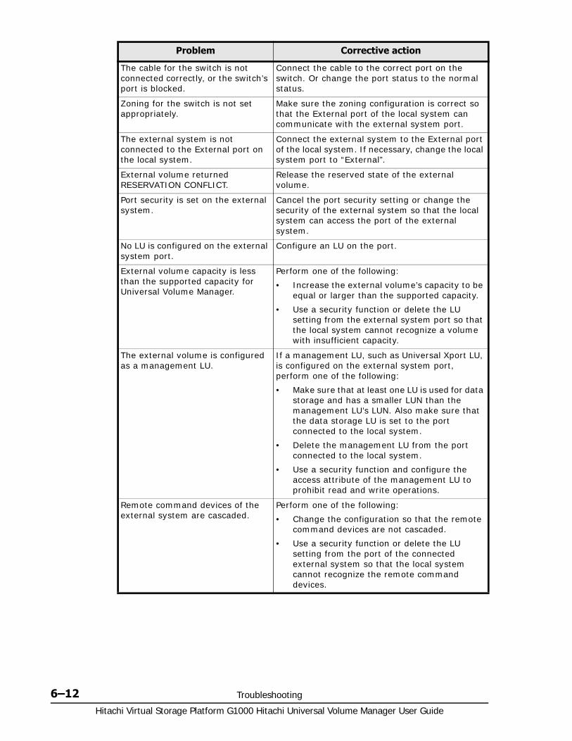
Hitachi Virtual Storage Platform G1000 Hitachi Universal Volume Manager User Guide
6–12 Troubleshooting
The cable for the switch is not connected correctly, or the switch’s port is blocked.
Connect the cable to the correct port on the switch. Or change the port status to the normal status.
Zoning for the switch is not set appropriately.
Make sure the zoning configuration is correct so that the External port of the local system can communicate with the external system port.
The external system is not connected to the External port on the local system.
Connect the external system to the External port of the local system. If necessary, change the local system port to “External”.
External volume returned RESERVATION CONFLICT.
Release the reserved state of the external volume.
Port security is set on the external system.
Cancel the port security setting or change the security of the external system so that the local system can access the port of the external system.
No LU is configured on the external system port.
Configure an LU on the port.
External volume capacity is less than the supported capacity for Universal Volume Manager.
Perform one of the following:
• Increase the external volume’s capacity to be equal or larger than the supported capacity.
• Use a security function or delete the LU setting from the external system port so that the local system cannot recognize a volume with insufficient capacity.
The external volume is configured as a management LU.
If a management LU, such as Universal Xport LU, is configured on the external system port, perform one of the following:
• Make sure that at least one LU is used for data storage and has a smaller LUN than the management LU’s LUN. Also make sure that the data storage LU is set to the port connected to the local system.
• Delete the management LU from the port connected to the local system.
• Use a security function and configure the access attribute of the management LU to prohibit read and write operations.
Remote command devices of the external system are cascaded.
Perform one of the following:
• Change the configuration so that the remote command devices are not cascaded.
• Use a security function or delete the LU setting from the port of the connected external system so that the local system cannot recognize the remote command devices.
Problem Corrective action

Troubleshooting 6–13Hitachi Virtual Storage Platform G1000 Hitachi Universal Volume Manager User Guide
If none of the actions suggested in the table provide volume discovery, remove the cable connection between the local and external storage systems, and then reconnect the storage systems. After 30 seconds, retry the operation.
External system information retrieved by port discovery is not found in the profile information.
Perform one of the following:
• Connect an external system supported by Universal Volume Manager.
• Call the Hitachi Data Systems Support Center to ask if the external system is supported by Universal Volume Manager. If the system is supported, install the microcode version that supports the external system or install the profile information of the external system.
Login to the external system failed. Perform one of the following:
• Make sure that the port of the external system is in Normal status.
• Register the WWN to the external system to allow login from the local system.
The external volume is not in Normal status, or a failure or error occurred in retrieving information from the external system.
Make sure that the external system or the external volume is in the Normal status.
Problem Corrective action

Hitachi Virtual Storage Platform G1000 Hitachi Universal Volume Manager User Guide
6–14 Troubleshooting
A
Supported external storage systems A–1Hitachi Virtual Storage Platform G1000 Hitachi Universal Volume Manager User Guide
Supported external storage systems
This topic provides required configuration settings for many of the supported external storage systems.
□ External systems
□ HUS VM Storage System
□ Virtual Storage Platform
□ Virtual Storage Platform G1000
□ Universal Storage Platform V/VM
□ Universal Storage Platform/TagmaStore NSC
□ Lightning 9900 V
□ Lightning 9900
□ Thunder 9500V
□ HUS/AMS/WMS
□ SVS200 storage system
□ EVA storage system
□ Sun StorEdge 6120/6320
□ Sun StorageTek FlexLine 380
□ Sun StorageTek 2540
Hitachi Virtual Storage Platform G1000 Hitachi Universal Volume Manager User Guide
A–2 Supported external storage systems
□ Sun StorageTek V2X2
□ EMC CLARiiON CX series
□ EMC VNX series
□ EMC Symmetrix series
□ IBM DS3000/DS4000/DS5000 series
□ IBM V7000 series
□ IBM SVC series
□ IBM XIV series
□ Fujitsu FibreCAT CX series
□ Fujitsu DX60/80/90 S2 and Fujitsu DX400 S2
□ SGI IS4600 series
□ 3Par T800, F400, V800, V400 series
□ Storage system with a product name displayed as "(Generic)"
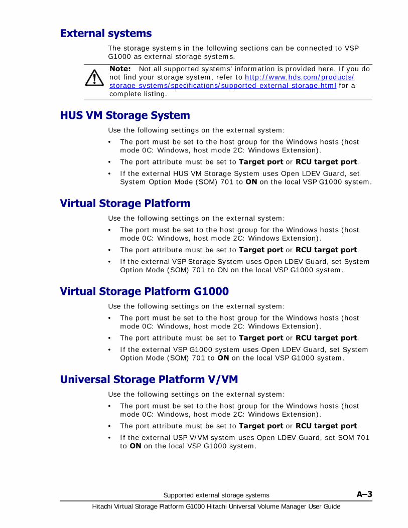
Supported external storage systems A–3Hitachi Virtual Storage Platform G1000 Hitachi Universal Volume Manager User Guide
External systemsThe storage systems in the following sections can be connected to VSP G1000 as external storage systems.
HUS VM Storage SystemUse the following settings on the external system:
• The port must be set to the host group for the Windows hosts (host mode 0C: Windows, host mode 2C: Windows Extension).
• The port attribute must be set to Target port or RCU target port.
• If the external HUS VM Storage System uses Open LDEV Guard, set System Option Mode (SOM) 701 to ON on the local VSP G1000 system.
Virtual Storage PlatformUse the following settings on the external system:
• The port must be set to the host group for the Windows hosts (host mode 0C: Windows, host mode 2C: Windows Extension).
• The port attribute must be set to Target port or RCU target port.
• If the external VSP Storage System uses Open LDEV Guard, set System Option Mode (SOM) 701 to ON on the local VSP G1000 system.
Virtual Storage Platform G1000Use the following settings on the external system:
• The port must be set to the host group for the Windows hosts (host mode 0C: Windows, host mode 2C: Windows Extension).
• The port attribute must be set to Target port or RCU target port.
• If the external VSP G1000 system uses Open LDEV Guard, set System Option Mode (SOM) 701 to ON on the local VSP G1000 system.
Universal Storage Platform V/VMUse the following settings on the external system:
• The port must be set to the host group for the Windows hosts (host mode 0C: Windows, host mode 2C: Windows Extension).
• The port attribute must be set to Target port or RCU target port.
• If the external USP V/VM system uses Open LDEV Guard, set SOM 701 to ON on the local VSP G1000 system.
Note: Not all supported systems’ information is provided here. If you do not find your storage system, refer to http://www.hds.com/products/storage-systems/specifications/supported-external-storage.html for a complete listing.

Hitachi Virtual Storage Platform G1000 Hitachi Universal Volume Manager User Guide
A–4 Supported external storage systems
Universal Storage Platform/TagmaStore NSC Use the following settings on the external system:
• The port must be set to the host group for the Windows hosts (host mode 0C: Windows, host mode 2C: Windows Extension).
• The port attribute must be set to Target port or RCU target port.
• If the external USP system uses Open LDEV Guard, set SOM 701 to ON on the local VSP G1000 system.
Host mode option for a volume larger than 2 TBIf a volume’s capacity is more than 2 TB, host mode option No. 24 must be enabled before mapping it as an external volume. For instructions, see the LUN Manager User's Guide for the Universal Storage Platform / TagmaStore NSC storage system.
Lightning 9900 V Use the following settings on the external system:
• The port must be set to the host group for the Windows hosts (host mode 0C: Windows, host mode 2C: Windows Extension).
• The port attribute must be set to Target port or RCU target port.
Lightning 9900Use the following settings on the external system:
• The port’s host mode must be set to PC Server (0C).
• The port attribute must be set to Target port or RCU target port.
Thunder 9500VThe following versions are recommended. If you use an earlier version, the SATA drive information may not display correctly.
• For Thunder 9530V, Thunder 9520V, Thunder 9570V: version 0658 or later.
• For Thunder 9580V, Thunder 9585V: version 1658 or later.
The following table shows the system parameters that must be specified for ports on the Thunder 9500V storage system.
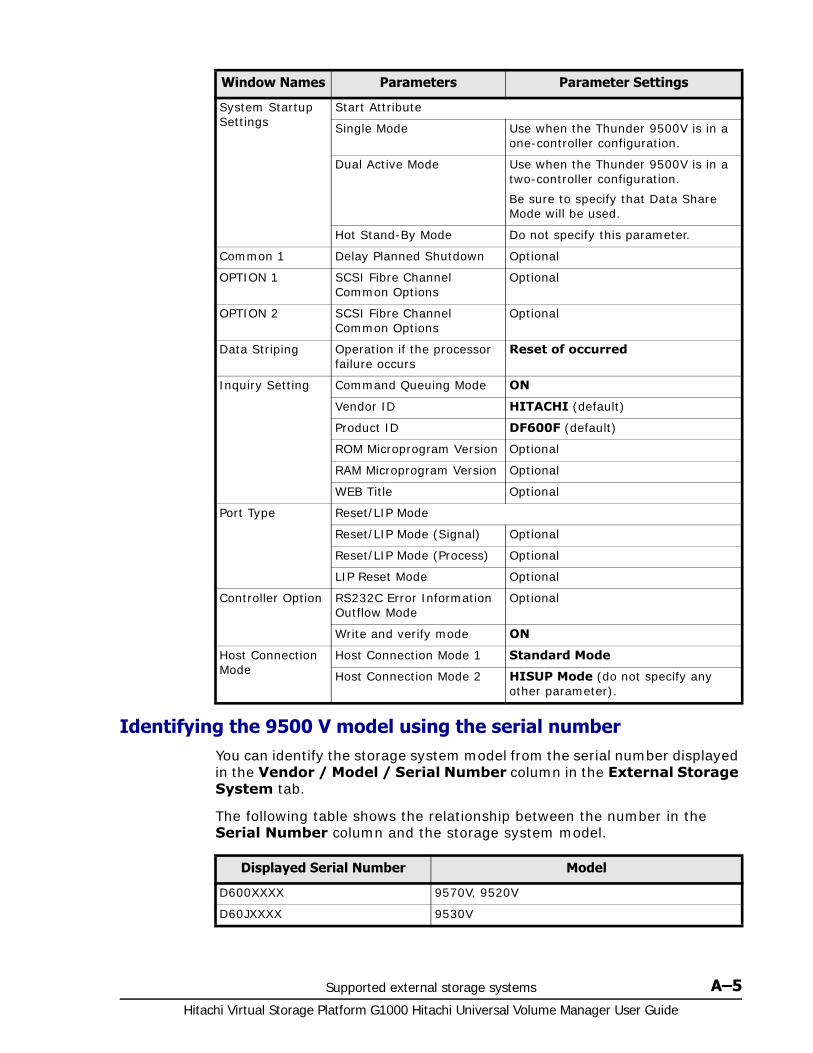
Supported external storage systems A–5Hitachi Virtual Storage Platform G1000 Hitachi Universal Volume Manager User Guide
Identifying the 9500 V model using the serial numberYou can identify the storage system model from the serial number displayed in the Vendor / Model / Serial Number column in the External Storage System tab.
The following table shows the relationship between the number in the Serial Number column and the storage system model.
Window Names Parameters Parameter Settings
System Startup Settings
Start Attribute
Single Mode Use when the Thunder 9500V is in a one-controller configuration.
Dual Active Mode Use when the Thunder 9500V is in a two-controller configuration.
Be sure to specify that Data Share Mode will be used.
Hot Stand-By Mode Do not specify this parameter.
Common 1 Delay Planned Shutdown Optional
OPTION 1 SCSI Fibre Channel Common Options
Optional
OPTION 2 SCSI Fibre Channel Common Options
Optional
Data Striping Operation if the processor failure occurs
Reset of occurred
Inquiry Setting Command Queuing Mode ON
Vendor ID HITACHI (default)
Product ID DF600F (default)
ROM Microprogram Version Optional
RAM Microprogram Version Optional
WEB Title Optional
Port Type Reset/LIP Mode
Reset/LIP Mode (Signal) Optional
Reset/LIP Mode (Process) Optional
LIP Reset Mode Optional
Controller Option RS232C Error Information Outflow Mode
Optional
Write and verify mode ON
Host Connection Mode
Host Connection Mode 1 Standard Mode
Host Connection Mode 2 HISUP Mode (do not specify any other parameter).
Displayed Serial Number Model
D600XXXX 9570V, 9520V
D60JXXXX 9530V

Hitachi Virtual Storage Platform G1000 Hitachi Universal Volume Manager User Guide
A–6 Supported external storage systems
Identifying the controller using the port WWNYou can identify the controller (controller 0 or controller 1) from the WWN of the port.
The following table describes the relationship between the port WWN and the controller.
HUS/AMS/WMS The table below shows the system parameters that must be specified for ports on HUS, AMS, and WMS storage systems when used with Universal Volume Manager. You can specify or omit any other parameters.
Also, ensure the following two settings using Storage Navigator Modular or Storage Navigator Modular2:
• Set the data transfer speed of the external port to a fixed value other than Auto.
• Set the data transfer speed of the target port of the HUS/AMS/WMS storage system to a fixed value consistent with the data transfer speed of the external port.
D60HXXXX 9580V, 9585V
Note: In serial numbers, "X" is an arbitrary number or character.
Displayed Serial Number Model
Model Controller WWN of Port
9570V
9530V
9520V
Controller 0 XXXXXXXXXXXXXXX0
XXXXXXXXXXXXXXX1
Controller 1 XXXXXXXXXXXXXXX2
XXXXXXXXXXXXXXX3
9580V
9585V
Controller 0 XXXXXXXXXXXXXXX0
XXXXXXXXXXXXXXX1
XXXXXXXXXXXXXXX2
XXXXXXXXXXXXXXX3
Controller 1 XXXXXXXXXXXXXXX4
XXXXXXXXXXXXXXX5
XXXXXXXXXXXXXXX6
XXXXXXXXXXXXXXX7
Note: In WWNs, "X" is an arbitrary number or character. The ports in the same physical storage system have the identical value.
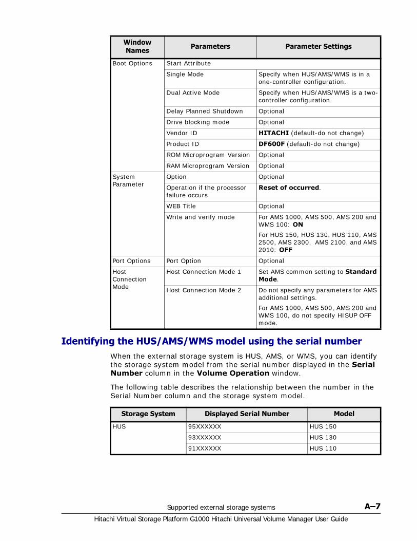
Supported external storage systems A–7Hitachi Virtual Storage Platform G1000 Hitachi Universal Volume Manager User Guide
Identifying the HUS/AMS/WMS model using the serial numberWhen the external storage system is HUS, AMS, or WMS, you can identify the storage system model from the serial number displayed in the Serial Number column in the Volume Operation window.
The following table describes the relationship between the number in the Serial Number column and the storage system model.
Window Names Parameters Parameter Settings
Boot Options Start Attribute
Single Mode Specify when HUS/AMS/WMS is in a one-controller configuration.
Dual Active Mode Specify when HUS/AMS/WMS is a two-controller configuration.
Delay Planned Shutdown Optional
Drive blocking mode Optional
Vendor ID HITACHI (default-do not change)
Product ID DF600F (default-do not change)
ROM Microprogram Version Optional
RAM Microprogram Version Optional
System Parameter
Option Optional
Operation if the processor failure occurs
Reset of occurred.
WEB Title Optional
Write and verify mode For AMS 1000, AMS 500, AMS 200 and WMS 100: ON
For HUS 150, HUS 130, HUS 110, AMS 2500, AMS 2300, AMS 2100, and AMS 2010: OFF
Port Options Port Option Optional
Host Connection Mode
Host Connection Mode 1 Set AMS common setting to Standard Mode.
Host Connection Mode 2 Do not specify any parameters for AMS additional settings.
For AMS 1000, AMS 500, AMS 200 and WMS 100, do not specify HISUP OFF mode.
Storage System Displayed Serial Number Model
HUS 95XXXXXX HUS 150
93XXXXXX HUS 130
91XXXXXX HUS 110

Hitachi Virtual Storage Platform G1000 Hitachi Universal Volume Manager User Guide
A–8 Supported external storage systems
When the model of HUS/AMS/WMS storage system is changed, the Serial Number is changed as well. If the HUS/AMS/WMS storage system is used as an external storage system, the mapped external volume may be blocked. To correct this problem, you can delete the mapping of the external volume and remap it to use the blocked external volume. See Requirements for external storage system maintenance on page 5-31 for detailed information on remapping.
Identifying the controller using the port WWN (HUS/AMS/WMS)When the external storage system is HUS, AMS, or WMS, you can identify the controller (controller 0 or controller 1) from the port WWN.
The following table describes the relationship between the port WWN and the controller.
AMS 87XXXXXX AMS 2500
85XXXXXX AMS 2300
83XXXXXX AMS 2100, AMS 2010
77XXXXXX AMS 1000
75XXXXXX AMS 500
73XXXXXX AMS 200
WMS 71XXXXXX WMS 100
In serial numbers, "X" is an arbitrary number or character.
Storage System Displayed Serial Number Model
Model Controller WWN of Port
AMS 200
WMS 100
Controller 0 XXXXXXXXXXXXXXX0
Controller 1 XXXXXXXXXXXXXXX1
AMS 2100
AMS 2010
AMS 500
Controller 0 XXXXXXXXXXXXXXX0
XXXXXXXXXXXXXXX1
Controller 1 XXXXXXXXXXXXXXX2
XXXXXXXXXXXXXXX3
HUS 110
HUS 130
AMS 2300
AMS 1000
Controller 0 XXXXXXXXXXXXXXX0
XXXXXXXXXXXXXXX1
XXXXXXXXXXXXXXX2
XXXXXXXXXXXXXXX3
Controller 1 XXXXXXXXXXXXXXX4
XXXXXXXXXXXXXXX5
XXXXXXXXXXXXXXX6
XXXXXXXXXXXXXXX7

Supported external storage systems A–9Hitachi Virtual Storage Platform G1000 Hitachi Universal Volume Manager User Guide
When the model of HUS/AMS/WMS storage system is changed, the WWN of the port is changed as well. If the HUS/AMS/WMS storage system is used as an external storage system, the mapped external path may be blocked. To correct this problem, you can delete the mapping of the external path and remap it to use the blocked external path. See Requirements for external storage system maintenance on page 5-31 for detailed information on remapping.
Identifying logical volumes using Characteristic1The Characteristic1 value is the internal LUN number of the LUNS from the AMS/WMS.
Caution on using the power savings option When an HUS 150, HUS 130, HUS 110, AMS 2500, AMS 2300, AMS 2100, or AMS 2010 storage system is connected as an external system with the Power Savings option is enabled, do not access external volumes from a host if the external volumes are spinning down. This prevents the external volume status from changing to Blockade.
If external volume status changes to Blockade, the volume is automatically restored in several hours. You can also manually restore the external volumes by reconnecting the external volume.
HUS and AMS 2000 series guidelines• Avoid unnecessary load to the external storage system. Path mode
between storage systems is Multi mode; therefore, when many external paths and mapping volumes are mapped, the load to the external
HUS 150
AMS 2500
Controller 0 XXXXXXXXXXXXXXX0
XXXXXXXXXXXXXXX1
XXXXXXXXXXXXXXX2
XXXXXXXXXXXXXXX3
XXXXXXXXXXXXXXX4
XXXXXXXXXXXXXXX5
XXXXXXXXXXXXXXX6
XXXXXXXXXXXXXXX7
Controller 1 XXXXXXXXXXXXXXX8
XXXXXXXXXXXXXXX9
XXXXXXXXXXXXXXXA
XXXXXXXXXXXXXXXB
XXXXXXXXXXXXXXXC
XXXXXXXXXXXXXXXD
XXXXXXXXXXXXXXXE
XXXXXXXXXXXXXXXF
Note: In WWNs, "X" is an arbitrary number or character. The ports in a physical storage system have the identical value.
Model Controller WWN of Port

Hitachi Virtual Storage Platform G1000 Hitachi Universal Volume Manager User Guide
A–10 Supported external storage systems
system is high; some commands from host to VSP G1000 or from VSP G1000 to the external system may time out. To keep the proper load, the following is recommended.
Specify two external paths. Set the paths to the ports of each controller of the AMS 2000 series system.
Set the queue to 500 or fewer commands issued at the same time from a AMS 2000 series system. The formula to calculate the number of queue commands per system is as follows.
(number of queues) x (number of external paths) x (number of concurrent external volume commands) < 500
For more information about command queue settings, see Editing external WWN settings on page 5-9.
• When using external volumes for replication, the copy operation needs to be distributed to two or more RAID groups.
There is an upper bound to the number of pairs that can be used for initial copy or resynchronization. Therefore, the copy operation may focus on a specific RAID group according to the order of the operation when it is performed to two or more external volumes.
If the copy operation focuses on a specific RAID group, then the AMS 2000 drive could bottleneck.
SVS200 storage systemUse the following settings on the external system:
• The port must be set to the host group for the Windows hosts (host mode 0C: Windows, host mode 2C: Windows Extension).
• The port attribute must be set to Target port or RCU target port.
EVA storage systemUse the following settings on the external system:
• The port must be configured as a target attached to a Windows host.
• EVA storage systems with microcode version 4.000 or later can be connected as an external system.
• On the local VSP G1000 storage system, set SOM 720 to ON for active path load-balancing support.
Set EVA system parameters in the following table. For parameters not shown, refer to the EVA system documentation for connection parameters.
The WWN of each VSP G1000 port connected to an EVA storage system must be registered to the EVA system. See EVA storage system documentation for details on registering WWNs
Parameter Parameter Setting
Add a Host Host OS Windows

Supported external storage systems A–11Hitachi Virtual Storage Platform G1000 Hitachi Universal Volume Manager User Guide
Identifying logical volumes using Characteristic2With an EVA external storage system, LUNs appear as Characteristic1 in Device Manager - Storage Navigator windows.
If you search for the logical volumes by specifying the WWN for EVA Port A as illustrated in the following figure, logical volumes LUN 1 and LUN 2 are found for each of HostGroup-1 and HostGroup-2.
In this case, two different logical volumes with the same name (LUN 1 and LUN 2) are found that can be connected from EVA Port A. But you cannot determine which LUN 1 and LUN 2 belong to HostGroup-1 or HostGroup-2 only by Characteristic1.
However, in Device Manager - Storage Navigator, you can identify the logical volumes referring to Characteristic2. The first 32 characters of Characteristic2 indicate the World Wide LUN Name. Identify the logical volume of the EVA storage system by this World Wide LUN Name.
Sun StorEdge 6120/6320
System Option Mode for connecting Sun StorEdge 6120/6320
When you connect Sun StorEdge 6120/6320 as an external storage system, you must set SOM 725 of the local storage system to ON. If SOM 725 is not set to ON, the external storage system might be blocked when performing maintenance tasks such as rebooting the controller of the external storage system before the firmware update.
For more information about using SOM 725, log on to the Hitachi Data Systems Support Portal: https://Portal.HDS.com.
System option parameters for connecting Sun StorEdge 6120/6320
The port must be configured as a target attached to a Windows host.
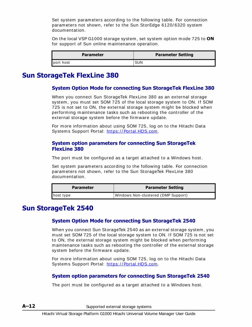
Hitachi Virtual Storage Platform G1000 Hitachi Universal Volume Manager User Guide
A–12 Supported external storage systems
Set system parameters according to the following table. For connection parameters not shown, refer to the Sun StorEdge 6120/6320 system documentation.
On the local VSP G1000 storage system, set system option mode 725 to ON for support of Sun online maintenance operation.
Sun StorageTek FlexLine 380
System Option Mode for connecting Sun StorageTek FlexLine 380
When you connect Sun StorageTek FlexLine 380 as an external storage system, you must set SOM 725 of the local storage system to ON. If SOM 725 is not set to ON, the external storage system might be blocked when performing maintenance tasks such as rebooting the controller of the external storage system before the firmware update.
For more information about using SOM 725, log on to the Hitachi Data Systems Support Portal: https://Portal.HDS.com.
System option parameters for connecting Sun StorageTek FlexLine 380
The port must be configured as a target attached to a Windows host.
Set system parameters according to the following table. For connection parameters not shown, refer to the Sun StorageTek FlexLine 380 documentation.
Sun StorageTek 2540
System Option Mode for connecting Sun StorageTek 2540
When you connect Sun StorageTek 2540 as an external storage system, you must set SOM 725 of the local storage system to ON. If SOM 725 is not set to ON, the external storage system might be blocked when performing maintenance tasks such as rebooting the controller of the external storage system before the firmware update.
For more information about using SOM 725, log on to the Hitachi Data Systems Support Portal: https://Portal.HDS.com.
System option parameters for connecting Sun StorageTek 2540
The port must be configured as a target attached to a Windows host.
Parameter Parameter Setting
port host SUN
Parameter Parameter Setting
host type Windows Non-clustered (DMP Support)
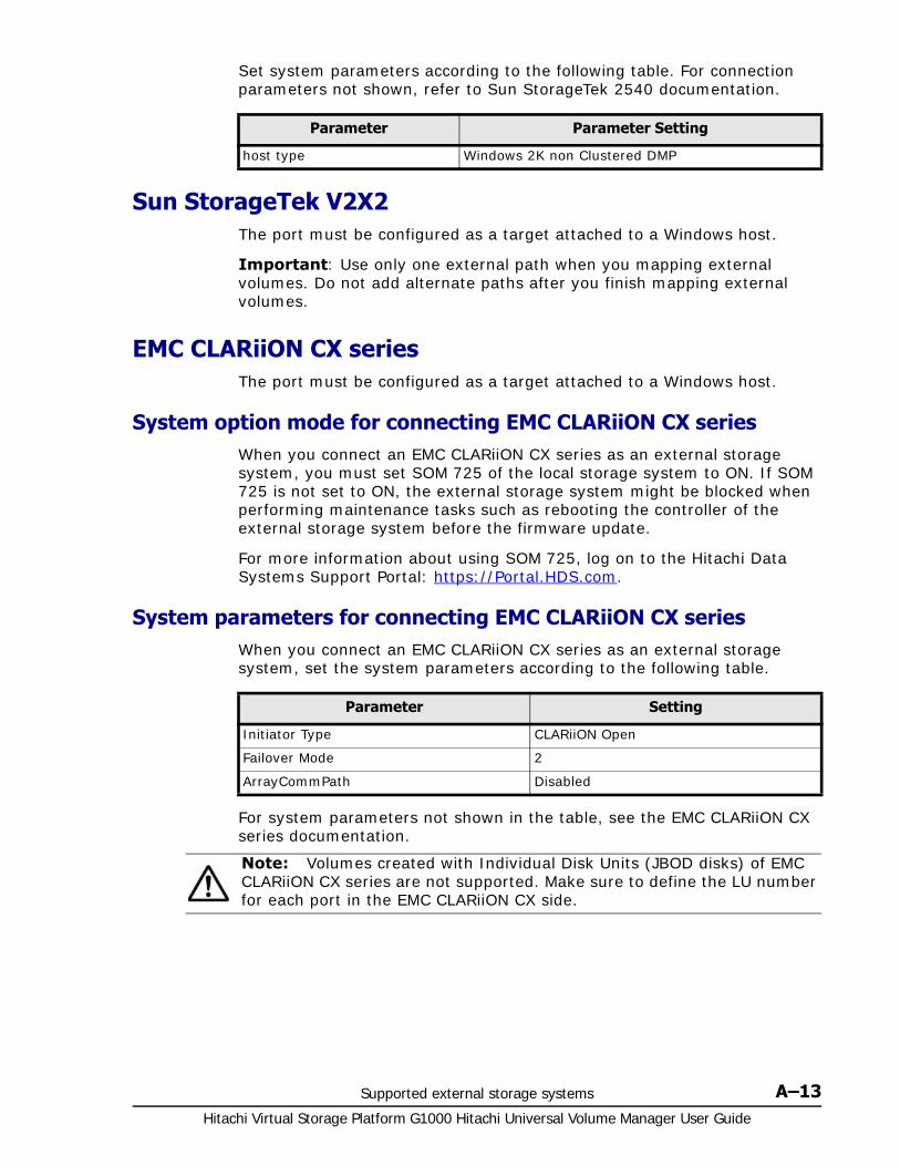
Supported external storage systems A–13Hitachi Virtual Storage Platform G1000 Hitachi Universal Volume Manager User Guide
Set system parameters according to the following table. For connection parameters not shown, refer to Sun StorageTek 2540 documentation.
Sun StorageTek V2X2The port must be configured as a target attached to a Windows host.
Important: Use only one external path when you mapping external volumes. Do not add alternate paths after you finish mapping external volumes.
EMC CLARiiON CX seriesThe port must be configured as a target attached to a Windows host.
System option mode for connecting EMC CLARiiON CX seriesWhen you connect an EMC CLARiiON CX series as an external storage system, you must set SOM 725 of the local storage system to ON. If SOM 725 is not set to ON, the external storage system might be blocked when performing maintenance tasks such as rebooting the controller of the external storage system before the firmware update.
For more information about using SOM 725, log on to the Hitachi Data Systems Support Portal: https://Portal.HDS.com.
System parameters for connecting EMC CLARiiON CX seriesWhen you connect an EMC CLARiiON CX series as an external storage system, set the system parameters according to the following table.
For system parameters not shown in the table, see the EMC CLARiiON CX series documentation.
Parameter Parameter Setting
host type Windows 2K non Clustered DMP
Parameter Setting
Initiator Type CLARiiON Open
Failover Mode 2
ArrayCommPath Disabled
Note: Volumes created with Individual Disk Units (JBOD disks) of EMC CLARiiON CX series are not supported. Make sure to define the LU number for each port in the EMC CLARiiON CX side.

Hitachi Virtual Storage Platform G1000 Hitachi Universal Volume Manager User Guide
A–14 Supported external storage systems
EMC VNX series
System option mode for connecting EMC VNX seriesWhen you connect an EMC VNX series as an external storage system, you must set SOM 725 of the local storage system to ON. If SOM 725 is not set to ON, the external storage system might be blocked when performing maintenance tasks such as rebooting the controller of the external storage system before the firmware update.
For more information about using SOM 725, log on to the Hitachi Data Systems Support Portal: https://Portal.HDS.com.
System parameters for connecting EMC VNX seriesWhen you connect an EMC VNX series as an external storage system, set the system parameters of the EMC VNX series according to the following table:
For system parameters not shown in the table, see the EMC VNX series documentation.
EMC Symmetrix seriesThe port must be configured as a target attached to a Windows host.
Set system parameters according to the following table. For connection parameters not shown, refer to EMC Symmetrix series documentation
On the local VSP G1000 system, system option mode 745 needs to be ON.
IBM DS3000/DS4000/DS5000 seriesThe port must be configured as a target attached to a Windows host.
Set system parameters according to the following table. For connection parameters not shown, refer to IBM DS3000/DS4000/DS5000 series documentation.
Parameter Setting
Initiator Type CLARiiON Open
Failover Mode 2
ArrayCommPath Disable
Note: Volumes created with Individual Disk Units (JBOD disks) of EMC VNX series are not supported. Make sure to define the LU number for each port in the EMC VNX side.
Parameter Parameter Setting
SC3 flag Enable
SPC2 flag Disable

Supported external storage systems A–15Hitachi Virtual Storage Platform G1000 Hitachi Universal Volume Manager User Guide
IBM V7000 seriesSet system parameters according to the following table. For connection parameters not shown, refer to the IBM V7000 series documentation.
Table A-1 System parameters for connecting IBM V7000 series
The model name of the IBM V7000 series is displayed as "SVC" on the Device Manager - Storage Navigator window.
IBM SVC seriesThe port must be configured as a target attached to a Windows host.
Set system parameters according to the following table. For connection parameters not shown, refer to IBM SVC series documentation.
IBM XIV seriesThe port must be configured as a target attached to a Windows host.
Device serial number differs between IBM XIV series and VSP G1000, as shown in the following table.
Fujitsu FibreCAT CX seriesThe port must be configured as a target attached to a Windows host.
Set system parameters according to the following table. For connection parameters not shown, refer to Fujitsu FibreCAT CX series documentation.
Parameter Parameter Setting
host type When alternate paths are connected to different clusters on the DS3000/DS4000/DS5000 series side: Linux
Parameter Parameter setting
host type Generic
Parameter Parameter Setting
host type Generic
Display in VSP G1000 Display in IBM XIV
Item Type Item Type
First 2 digits of Serial Number
Decimal value First 2 digits of (System) Serial number
Decimal value
Last 5 digits of Serial Number
Hexadecimal value
Last 5 digits of (System) Serial number
Decimal value
Characteristic 1 Hexadecimal value
Device serial number Decimal value

Hitachi Virtual Storage Platform G1000 Hitachi Universal Volume Manager User Guide
A–16 Supported external storage systems
Volumes created with the RAID0 level or Individual Disk Units (JBOD disks) of Fujitsu FibreCAT CX series are not supported.
System option mode for connecting Fujitsu FibreCAT CX series
When you connect the Fujitsu FibreCAT CX series as an external storage system, you must set SOM 725 of the local storage system to ON. If SOM 725 is not set to ON, the external storage system might be blocked when a maintenance task such as rebooting the controller of the external storage system is performed before the firmware update.
For more information about using SOM 725, log on to the Hitachi Data Systems Support Portal: https://Portal.HDS.com.
Fujitsu DX60/80/90 S2 and Fujitsu DX400 S2The port must be configured as a target attached to a Windows host.
Set system parameters according to the following table. For connection parameters not shown, refer to Fujitsu DX60/80/90 S2 or Fujitsu DX 400 S2 documentation.
SGI IS4600 seriesThe port must be configured as a target attached to a Windows host.
Set system parameters according to the following table. For connection parameters not shown, refer to SGI IS4600 series documentation.
3Par T800, F400, V800, V400 seriesThe port must be configured as a target attached to a windows host.
Set system parameters according to the following tables. For connection parameters not shown, refer to 3Par T800, F400, V800 or V400 series documentation.
Parameter Parameter Setting
Initiator Type CLARiiON Open
Failover Mode 2
Parameter Parameter Setting
Inquiry VPD ID Type in Setup Host Response screen
Type1 + Type3
Load Balance Response in Setup Host Response screen
Busy
Parameter Parameter Setting
host type When alternate paths are connected to different clusters on the SGI IS4600 series side: Linux

Supported external storage systems A–17Hitachi Virtual Storage Platform G1000 Hitachi Universal Volume Manager User Guide
For 3Par T800 and F400 series
For 3Par V800 and V400 series
The volumes in which "Dynamic optimization" or "Adaptive optimization" is applied must not be used as the external volume of VSP G1000; otherwise the performance of the external volume may possibly be degraded and the operation cannot be guaranteed.
Storage system with a product name displayed as "(Generic)"
The generic Universal Volume Manager profile (available with 70-04-x) provides support for connecting Fibre channel attached, external storage systems without testing them individually. It will automatically support storage systems that conform to a subset of the standard SCSI Primary Commands. (If you need further information, please contact the Hitachi Data Systems Support Center). An HDS representative can perform a step-wise process to install and connect external storage. These steps (defined below) follow a standard process to ensure that no obvious problems exist in the virtualization. Updating a VSP G1000 to the minimum firmware level 70-05-0x automatically installs the generic UVM profile and makes it available.
Support conditions when product name displays as “(Generic)”When an external storage system is connected to a VSP G1000 and is supported with the generic UVM profile, the following support conditions exist.
• Vendor name that corresponds to the external storage system is displayed.
• Product name is displayed as “Generic”.
• Serial number is not displayed.
• Characteristic1(device information). LUN assigned to the path with the highest priority is displayed.
Parameter Parameter Setting
host mode generic-legacy (or generic)
Parameter Parameter Setting
host mode generic-legacy
Note: If multiple generic storage systems of the same vendor are connected, they are displayed as a single storage system. As a result, if Disconnect External Storage Systems or Reconnect External Storage Systems is run for generic storage systems, all the generic storage system volumes are disconnected or reconnected. For disconnecting or reconnecting a particular generic storage system volume, the best practice is to run the command in the external volume unit rather than the external storage system unit.
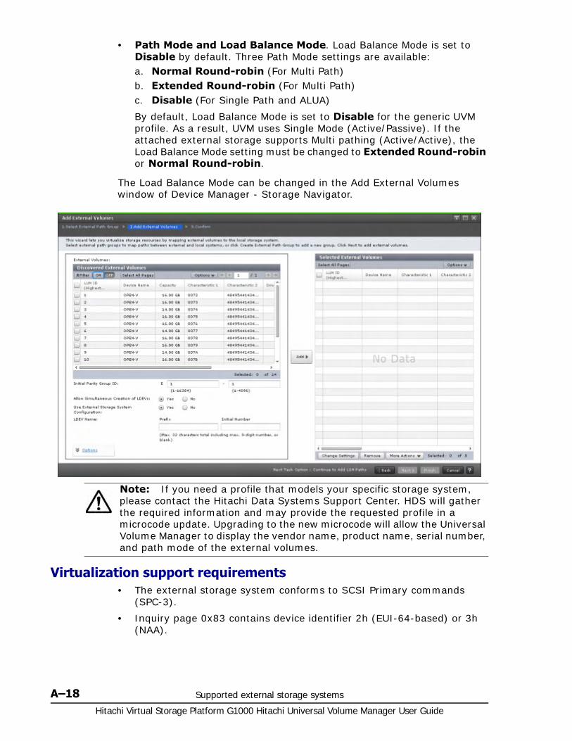
Hitachi Virtual Storage Platform G1000 Hitachi Universal Volume Manager User Guide
A–18 Supported external storage systems
• Path Mode and Load Balance Mode. Load Balance Mode is set to Disable by default. Three Path Mode settings are available:a. Normal Round-robin (For Multi Path)b. Extended Round-robin (For Multi Path)c. Disable (For Single Path and ALUA)
By default, Load Balance Mode is set to Disable for the generic UVM profile. As a result, UVM uses Single Mode (Active/Passive). If the attached external storage supports Multi pathing (Active/Active), the Load Balance Mode setting must be changed to Extended Round-robin or Normal Round-robin.
The Load Balance Mode can be changed in the Add External Volumes window of Device Manager - Storage Navigator.
Virtualization support requirements• The external storage system conforms to SCSI Primary commands
(SPC-3).
• Inquiry page 0x83 contains device identifier 2h (EUI-64-based) or 3h (NAA).
Note: If you need a profile that models your specific storage system, please contact the Hitachi Data Systems Support Center. HDS will gather the required information and may provide the requested profile in a microcode update. Upgrading to the new microcode will allow the Universal Volume Manager to display the vendor name, product name, serial number, and path mode of the external volumes.
Supported external storage systems A–19Hitachi Virtual Storage Platform G1000 Hitachi Universal Volume Manager User Guide
• The alternate path mode is not Active/Standby. (Active/Standby is a Single Mode much like Active/Passive, but it does not failover automatically.)
• A profile specific to the storage system does not exist.
• A special device driver or path manager is not required to control the external storage system.
• All other restrictions referenced in this guide apply to virtualization specifications.
Suggested virtualization procedure1. Set up VSP G1000 External ports.
2. Connect the external storage FC ports to the VSP G1000 External ports.
3. Virtualize at least four LUNs from the external storage.
- If virtualization fails, please contact the Hitachi Data Systems Support Center.
4. Connect two FC ports of the VSP G1000 to two HBAs of the server.
5. Provision the ELUNs mapped to the LUNs (step 3) on the ES to the UVM FC ports.
6. Run an I/O generator to the virtualized LUNs. IOMETER or VDBENCH can be used.a. Delete the external path of the highest priority during the I/O.b. Add the external path as the highest priority during the I/O.
7. Stop the I/O.
Note: The collection of information is optional but recommended. HDS asks that if new branded storage is attached that the local HDS representative collect the required data to send to Hitachi. After reviewing the data, Hitachi will add the External Storage Model to a listing of supported models on the HDS website. Hitachi may also provide a profile that models your specific storage system. You have the option of continuing to use the external storage system or waiting for your customized profile. If the required data is not provided, HDS support may be limited until the data is sent to Hitachi.

Hitachi Virtual Storage Platform G1000 Hitachi Universal Volume Manager User Guide
A–20 Supported external storage systems

B
Remote command devices B–1Hitachi Virtual Storage Platform G1000 Hitachi Universal Volume Manager User Guide
Remote command devices
This topic provides information for mapping to command devices in external storage systems.
□ Overview of remote command devices
□ Storage systems supported for remote command devices
□ Requirements
□ Restrictions and other information
□ Mapping a command device

Hitachi Virtual Storage Platform G1000 Hitachi Universal Volume Manager User Guide
B–2 Remote command devices
Overview of remote command devices You can map to a volume used as a command device in an external system. From the local system, the mapped command device volume becomes a remote command device.
A Universal Volume Manager license is not required for a remote command device mapping operation.
From an OPEN-systems host connected to the local system, you can issue ShadowImage, TrueCopy, or other commands from Command Control Interface (CCI) to the remote command device. The commands are relayed from the remote command device to the external system where they are executed for pairs such as those for ShadowImage and TrueCopy. This process is outlined in the following figure.
Storage systems supported for remote command devicesYou can map a command device in one of the following external storage system as a remote command device in VSP G1000:
• VSP G1000
• Unified Storage VM
• Virtual Storage Platform
• Universal Storage Platform V
Figure B-1 Outline of remote command device
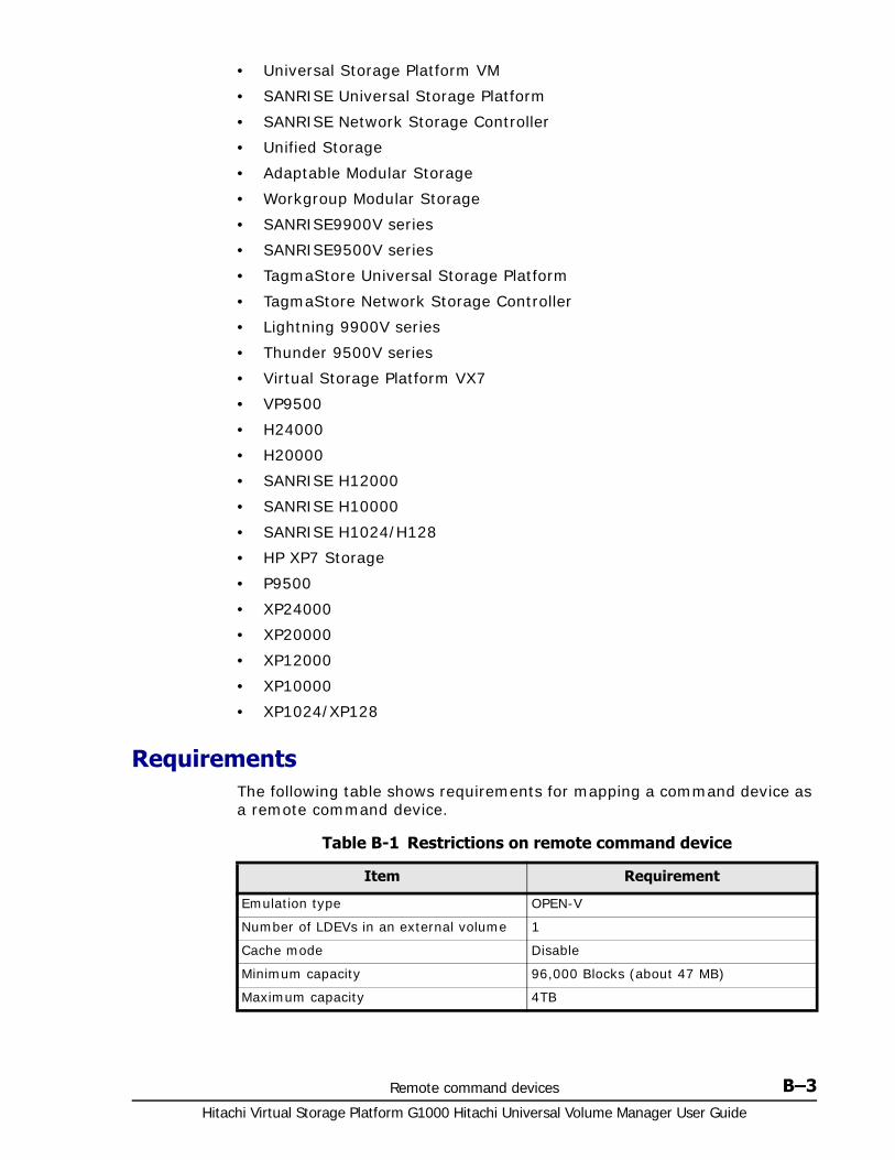
Remote command devices B–3Hitachi Virtual Storage Platform G1000 Hitachi Universal Volume Manager User Guide
• Universal Storage Platform VM
• SANRISE Universal Storage Platform
• SANRISE Network Storage Controller
• Unified Storage
• Adaptable Modular Storage
• Workgroup Modular Storage
• SANRISE9900V series
• SANRISE9500V series
• TagmaStore Universal Storage Platform
• TagmaStore Network Storage Controller
• Lightning 9900V series
• Thunder 9500V series
• Virtual Storage Platform VX7
• VP9500
• H24000
• H20000
• SANRISE H12000
• SANRISE H10000
• SANRISE H1024/H128
• HP XP7 Storage
• P9500
• XP24000
• XP20000
• XP12000
• XP10000
• XP1024/XP128
Requirements The following table shows requirements for mapping a command device as a remote command device.
Table B-1 Restrictions on remote command device
Item Requirement
Emulation type OPEN-V
Number of LDEVs in an external volume 1
Cache mode Disable
Minimum capacity 96,000 Blocks (about 47 MB)
Maximum capacity 4TB
Hitachi Virtual Storage Platform G1000 Hitachi Universal Volume Manager User Guide
B–4 Remote command devices
Restrictions and other informationBefore mapping a command device as a remote command device, note the following information.
• The remote command device cannot be identified by port discovery or volume discovery process that takes place during the mapping operation.
• When an external storage system (A) has a remote command device (B) (that is, when a command device in another external storage system (C) is mapped to this external storage system (A)), make sure that the remote command device (B) does not have the smallest LUN on the port in the external storage system (A).
• You cannot execute I/O to the remote command device.
• You cannot set command device disable on the remote command device.
• You cannot set command device security on the remote command device.
• Do not set the command device security on the external storage system side for the command device that is mapped as a remote command device.
• You cannot create CVs using the VLL function in the remote command device.
• Cache Residency Manager is not available on the remote command device.
• Command device information reported to the local host by the remote command device includes the following:
Serial number
Vendor
Device name. The name displayed for many individual storage system is listed in Supported external systems path mode for external volumes on page 2-17.
• Errors can occur when operations are performed on the remote command device, even though the status of the remote command device is normal. In this case, check the status of the command device on the external storage system where the error actually exists.
Mapping a command device To map a command device, select a command device that can be mapped and follow the procedure in Mapping an external volume on page 4-5.
Maximum number of the available CCI instances per remote command device
16*
* Maximum number of available CCI instances may be less than 16, dependent upon the number of paths between a local storage system and an external storage system.
Item Requirement

Remote command devices B–5Hitachi Virtual Storage Platform G1000 Hitachi Universal Volume Manager User Guide
When mapped, the remote command device appears in the Device Manager - Storage Navigator Mapped Volumes window, Device Name column as follows:
Storage system Displayed information in Device Name column
VSP G1000
Unified Storage VM
Virtual Storage Platform
Universal Storage Platform V
Universal Storage Platform VM
SANRISE Universal Storage Platform
SANRISE Network Storage Controller
SANRISE9900V series
TagmaStore Universal Storage Platform
TagmaStore Network Storage Controller
Lightning 9900V series
Virtual Storage Platform VX7
VP9500
H24000
H20000
SANRISE H12000
SANRISE H1024/H128
HP XP7 Storage
XP24000
P9500
XP24000
XP20000
XP12000
XP10000
XP1024/XP128
Format: "Emulation Type" + "-CM"
Example: OPEN V-CM
Unified Storage
Adaptable Modular Storage
Workgroup Modular Storage
SANRISE9500V series
Thunder 9500V series
DF600F-CM

Hitachi Virtual Storage Platform G1000 Hitachi Universal Volume Manager User Guide
B–6 Remote command devices
C
Command Control Interface command reference C–1Hitachi Virtual Storage Platform G1000 Hitachi Universal Volume Manager User Guide
Command Control Interface commandreference
This topic lists Command Control Interface (CCI) commands that correspond to the Actions you select in Device Manager - Storage Navigator.
□ Device Manager - Storage Navigator Action names and CCI commands
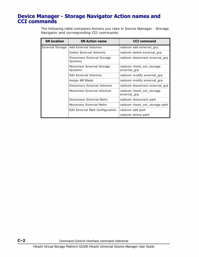
Hitachi Virtual Storage Platform G1000 Hitachi Universal Volume Manager User Guide
C–2 Command Control Interface command reference
Device Manager - Storage Navigator Action names and CCI commands
The following table compares Actions you take in Device Manager - Storage Navigator and corresponding CCI commands.
SN location SN Action name CCI command
External Storage Add External Volumes raidcom add external_grp
Delete External Volumes raidcom delete external_grp
Disconnect External Storage Systems
raidcom disconnect external_grp
Reconnect External Storage Systems
raidcom check_ext_storage external_grp
Edit External Volumes raidcom modify external_grp
Assign MP Blade raidcom modify external_grp
Disconnect External Volumes raidcom disconnect external_grp
Reconnect External Volumes raidcom check_ext_storage external_grp
Disconnect External Paths raidcom disconnect path
Reconnect External Paths raidcom check_ext_storage path
Edit External Path Configuration raidcom add path
raidcom delete path

D
Universal Volume Manager GUI reference D–1Hitachi Virtual Storage Platform G1000 Hitachi Universal Volume Manager User Guide
Universal Volume Manager GUIreference
This appendix describes Device Manager - Storage Navigator windows, dialog boxes, and fields related to Universal Volume Manager.
□ External Storage window
□ Selected external storage system window
□ Selected external path group window
□ Add External Volumes wizard
□ Edit Policies window
□ Edit External Volumes wizard
□ Edit External Path Configuration wizard
□ Edit External WWNs wizard
□ Delete External Volumes wizard
□ Disconnect External Paths wizard
□ Reconnect External Paths wizard
□ Discover External Target Ports window
□ Create External Path Group window
□ Change Settings window

Hitachi Virtual Storage Platform G1000 Hitachi Universal Volume Manager User Guide
D–2 Universal Volume Manager GUI reference
□ View External LUN Properties window
□ Reconnect External Storage Systems window
□ Reconnect External Volumes window
□ Disconnect External Storage Systems window
□ Disconnect External Volumes window
□ Assign MP Blade wizard
□ External LDEV Properties window
□ Discovery Result Detail window

Universal Volume Manager GUI reference D–3Hitachi Virtual Storage Platform G1000 Hitachi Universal Volume Manager User Guide
External Storage window Use this window to view external storage systems.
You can perform these operations from the window:
• Mapping an external volume on page 4-5
• Editing mapping policies on page 5-4
• Disconnecting an external path on page 5-13
• Reconnecting an external path on page 5-14
Information areas in this window:
• Summary on page D-3
• External Storage Systems tab on page D-3
• External Paths tab on page D-5
Summary
Displays summary information for external storage.
External Storage Systems tab
Displays the external storage systems in which mapped external volumes reside.
Item Description
Number of External Storage Systems
Number of external storage systems in which mapped external volumes reside.
Number of External Paths Number of external paths.
Number of External Volumes
Number of mapped external volumes.
External Volume Capacity Total capacity of mapped external volumes.

Hitachi Virtual Storage Platform G1000 Hitachi Universal Volume Manager User Guide
D–4 Universal Volume Manager GUI reference
Item Description
Vendor / Model / Serial Number
Identifying information for the selected external storage system.
When the link is clicked, more information for the system is shown.
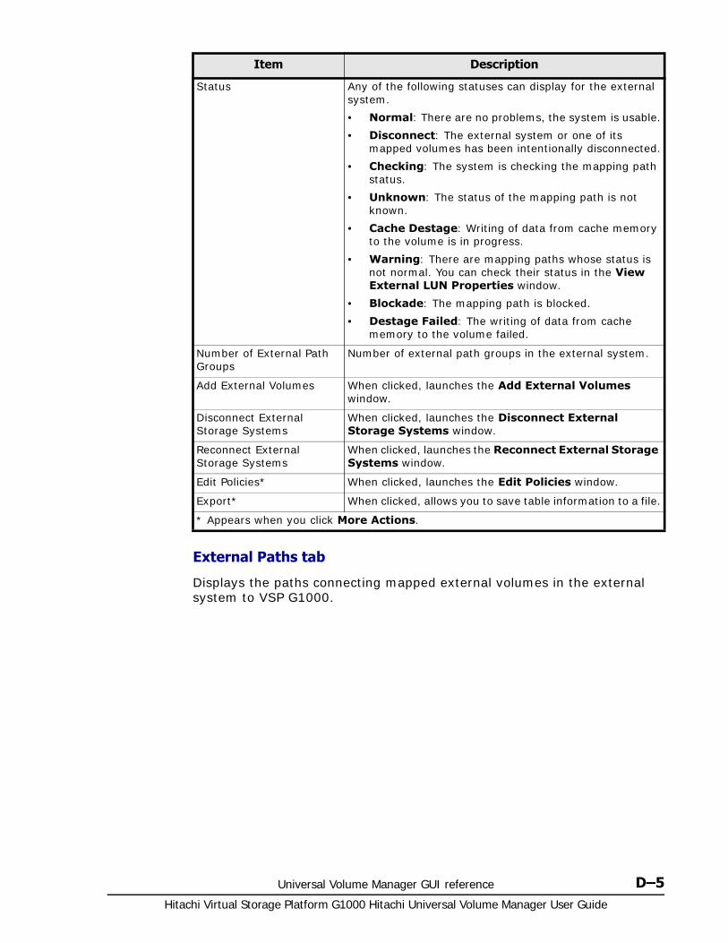
Universal Volume Manager GUI reference D–5Hitachi Virtual Storage Platform G1000 Hitachi Universal Volume Manager User Guide
External Paths tab
Displays the paths connecting mapped external volumes in the external system to VSP G1000.
Status Any of the following statuses can display for the external system.
• Normal: There are no problems, the system is usable.
• Disconnect: The external system or one of its mapped volumes has been intentionally disconnected.
• Checking: The system is checking the mapping path status.
• Unknown: The status of the mapping path is not known.
• Cache Destage: Writing of data from cache memory to the volume is in progress.
• Warning: There are mapping paths whose status is not normal. You can check their status in the View External LUN Properties window.
• Blockade: The mapping path is blocked.
• Destage Failed: The writing of data from cache memory to the volume failed.
Number of External Path Groups
Number of external path groups in the external system.
Add External Volumes When clicked, launches the Add External Volumes window.
Disconnect External Storage Systems
When clicked, launches the Disconnect External Storage Systems window.
Reconnect External Storage Systems
When clicked, launches the Reconnect External Storage Systems window.
Edit Policies* When clicked, launches the Edit Policies window.
Export* When clicked, allows you to save table information to a file.
* Appears when you click More Actions.
Item Description
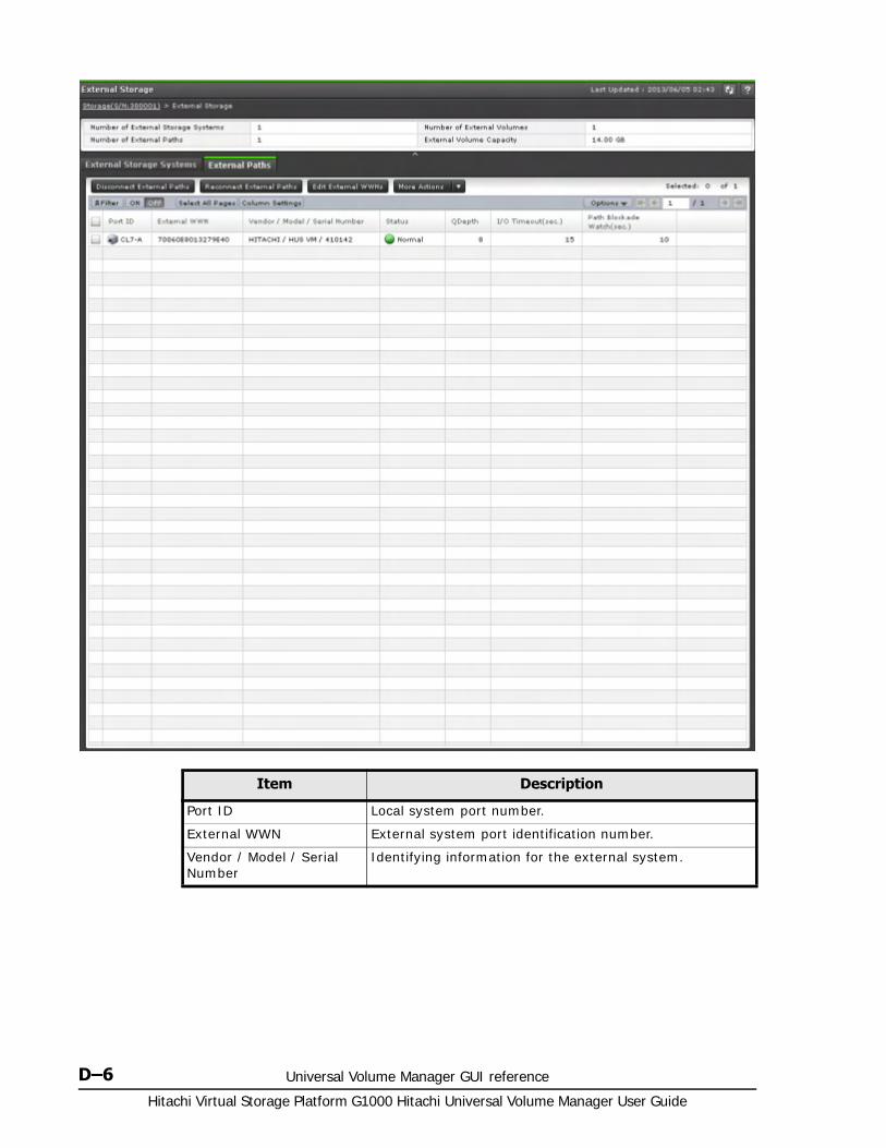
Hitachi Virtual Storage Platform G1000 Hitachi Universal Volume Manager User Guide
D–6 Universal Volume Manager GUI reference
Item Description
Port ID Local system port number.
External WWN External system port identification number.
Vendor / Model / Serial Number
Identifying information for the external system.

Universal Volume Manager GUI reference D–7Hitachi Virtual Storage Platform G1000 Hitachi Universal Volume Manager User Guide
Selected external storage system windowUse this window to view information about the selected external storage system.
You can perform these operations from the window:
• Mapping an external volume on page 4-5
• Adding an external path to an existing path group on page 5-11
• Changing external path priority on page 5-12
• Removing, replacing an external path on page 5-16
• Editing external volume policies (settings) on page 5-2
• Export table information to a file.
Information areas in this window:
• Summary on page D-8
• External Path Groups tab on page D-9
Status Status of external paths.
• Normal: There are no problems, the system is usable.
• Disconnect: The path has been intentionally disconnected.
• Checking: The system is checking the external path status.
• Unknown: The status of the external path is not known.
• Warning: There are external paths whose status is not normal. You can check their status in the View External LUN Properties window.
• Blockade: The external path is blocked.
QDepth Number of Read/Write commands that can be queued to the external volume. 8 is set by default.
I/O Timeout (sec.) Number of seconds that should pass before I/O to the external volume times out. 15 seconds is the default.
Path Blockade Watch(sec.) Time that will elapse from the time that a path goes down to the time when the external volume is blocked. 10 seconds is the default.
Disconnect External Paths When clicked, launches the Disconnect External Paths window.
Reconnect External Paths When clicked, launches the Reconnect External Paths window.
Edit External WWNs When clicked, launches the Edit External WWNs window.
Edit Policies* When clicked, launches the Edit Policies window.
Export* When clicked, allows you to save table information to a file.
* Appears when you click More Actions.
Item Description
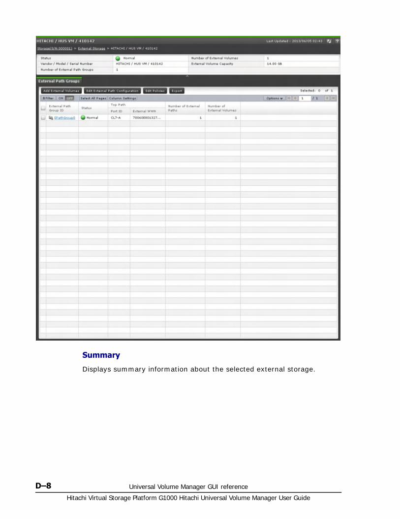
Hitachi Virtual Storage Platform G1000 Hitachi Universal Volume Manager User Guide
D–8 Universal Volume Manager GUI reference
Summary
Displays summary information about the selected external storage.
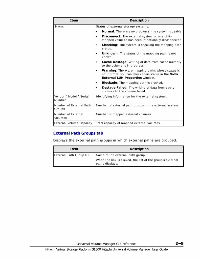
Universal Volume Manager GUI reference D–9Hitachi Virtual Storage Platform G1000 Hitachi Universal Volume Manager User Guide
External Path Groups tab
Displays the external path groups in which external paths are grouped.
Item Description
Status Status of external storage systems.
• Normal: There are no problems, the system is usable.
• Disconnect: The external system or one of its mapped volumes has been intentionally disconnected.
• Checking: The system is checking the mapping path status.
• Unknown: The status of the mapping path is not known.
• Cache Destage: Writing of data from cache memory to the volume is in progress.
• Warning: There are mapping paths whose status is not normal. You can check their status in the View External LUN Properties window.
• Blockade: The mapping path is blocked.
• Destage Failed: The writing of data from cache memory to the volume failed.
Vendor / Model / Serial Number
Identifying information for the external system.
Number of External Path Groups
Number of external path groups in the external system.
Number of External Volumes
Number of mapped external volumes.
External Volume Capacity Total capacity of mapped external volumes.
Item Description
External Path Group ID Name of the external path group.
When the link is clicked, the list of the group’s external paths displays.
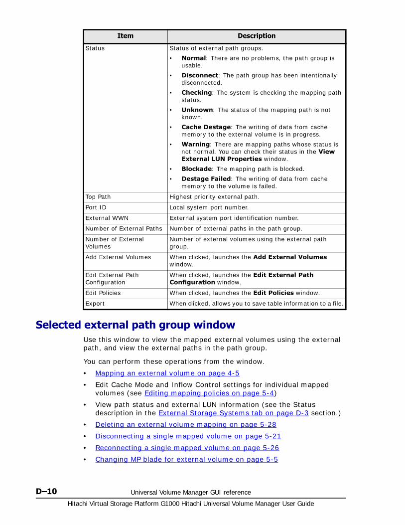
Hitachi Virtual Storage Platform G1000 Hitachi Universal Volume Manager User Guide
D–10 Universal Volume Manager GUI reference
Selected external path group windowUse this window to view the mapped external volumes using the external path, and view the external paths in the path group.
You can perform these operations from the window.
• Mapping an external volume on page 4-5
• Edit Cache Mode and Inflow Control settings for individual mapped volumes (see Editing mapping policies on page 5-4)
• View path status and external LUN information (see the Status description in the External Storage Systems tab on page D-3 section.)
• Deleting an external volume mapping on page 5-28
• Disconnecting a single mapped volume on page 5-21
• Reconnecting a single mapped volume on page 5-26
• Changing MP blade for external volume on page 5-5
Status Status of external path groups.
• Normal: There are no problems, the path group is usable.
• Disconnect: The path group has been intentionally disconnected.
• Checking: The system is checking the mapping path status.
• Unknown: The status of the mapping path is not known.
• Cache Destage: The writing of data from cache memory to the external volume is in progress.
• Warning: There are mapping paths whose status is not normal. You can check their status in the View External LUN Properties window.
• Blockade: The mapping path is blocked.
• Destage Failed: The writing of data from cache memory to the volume is failed.
Top Path Highest priority external path.
Port ID Local system port number.
External WWN External system port identification number.
Number of External Paths Number of external paths in the path group.
Number of External Volumes
Number of external volumes using the external path group.
Add External Volumes When clicked, launches the Add External Volumes window.
Edit External Path Configuration
When clicked, launches the Edit External Path Configuration window.
Edit Policies When clicked, launches the Edit Policies window.
Export When clicked, allows you to save table information to a file.
Item Description

Universal Volume Manager GUI reference D–11Hitachi Virtual Storage Platform G1000 Hitachi Universal Volume Manager User Guide
• Editing external volume policies (settings) on page 5-2
• Export table information to a file (see the Export button description in External Storage Systems tab on page D-3 section.)
Information areas in this window:
• Summary on page D-11
• Mapped Volumes tab on page D-11
• External Paths tab on page D-16
Summary
Displays summary information about the selected external path group.
Mapped Volumes tab
Displays the external volumes mapped to the VSP G1000 using the selected path group.
Item Description
Status Status of path groups.
• Normal: There are no problems, the path group is usable.
• Disconnect: The path group has been intentionally disconnected.
• Checking: The system is checking the mapping path status.
• Unknown: The status of the mapping path is not known.
• Cache Destage: The writing of data from cache memory to the external volume is in progress.
• Warning: There are mapping paths whose status is not normal. You can check their status in the View External LUN Properties window.
• Blockade: The mapping path is blocked.
• Destage Failed: The writing of data from cache memory to the volume is failed.
Vendor / Model / Serial Number
Identifying information for the external system.
Number of External Paths Number of external paths in the external path group.
Number of External Volumes
Number of mapped external volumes using the external path group.
External Volume Capacity Total capacity of mapped external volumes using the path group.

Hitachi Virtual Storage Platform G1000 Hitachi Universal Volume Manager User Guide
D–12 Universal Volume Manager GUI reference
Item Description
Parity Group ID Displays parity group numbers for the mapped external volumes. When the link is clicked, a list of LDEVs in the mapped volume and parity group displays.
When the link is clicked, a list of LDEVs in the mapped volume and parity group displays.
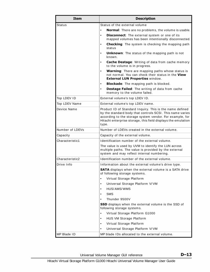
Universal Volume Manager GUI reference D–13Hitachi Virtual Storage Platform G1000 Hitachi Universal Volume Manager User Guide
Status Status of the external volume
• Normal: There are no problems, the volume is usable.
• Disconnect: The external system or one of its mapped volumes has been intentionally disconnected.
• Checking: The system is checking the mapping path status
• Unknown: The status of the mapping path is not known.
• Cache Destage: Writing of data from cache memory to the volume is in progress.
• Warning: There are mapping paths whose status is not normal. You can check their status in the View External LUN Properties window.
• Blockade: The mapping path is blocked.
• Destage Failed: The writing of data from cache memory to the volume failed.
Top LDEV ID External volume’s top LDEV ID.
Top LDEV Name External volume’s top LDEV name.
Device Name Product ID of Standard Inquiry. This is the name defined by the standard body that controls SCSI. This name varies according to the storage system vendor. For example, for Hitachi enterprise storage, this field displays the emulation type.
Number of LDEVs Number of LDEVs created in the external volume.
Capacity Capacity of the external volume.
Characteristic1 Identification number of the external volume.
The value is used by UVM to identify the LUN across multiple paths. The value is provided by the external system and may reflect internal numbering.
Characteristic2 Identification number of the external volume.
Drive Info Information about the external volume’s drive type.
SATA displays when the external volume is a SATA drive of following storage systems.
• Virtual Storage Platform
• Universal Storage Platform V/VM
• HUS/AMS/WMS
• SMS
• Thunder 9500V
SSD displays when the external volume is the SSD of following storage systems.
• Virtual Storage Platform G1000
• HUS VM Storage Platform
• Virtual Storage Platform
• Universal Storage Platform V/VM
MP Blade ID MP blade IDs allocated to the external volume.
Item Description

Hitachi Virtual Storage Platform G1000 Hitachi Universal Volume Manager User Guide
D–14 Universal Volume Manager GUI reference
Path Mode Path mode for the external volume’s external path.
• Single: Ordinarily, only one external path is used even if alternate paths are set. Alternate paths are available in case of failure.
• Multi: Multiple paths are used at the same time.
• ALUA: Like Multi, all paths are used; however, they are not used when connected to ports in Passive status.
See External paths on page 2-14 for more information.
Path Mode on Profile1 Displays the path mode on the profile information of the external storage system.
• Single: Ordinarily, only one external path is used even if alternate paths are set.
• Multi: When alternate paths are set, external paths from several ports are used simultaneously with load balancing.
ALUA Settable1 Displays whether ALUA can be set as the Path Mode in the external storage system.
• Enable: Enables ALUA Mode.
• Disable: Disables ALUA Mode.
ALUA Permitted1 Displays whether ALUA can be set as the Path Mode in the local storage system.
• Enable: ALUA Mode is used.
Disable: ALUA Mode is not used.
Load Balance Mode Displays I/O load balance system for external storage system.
• Normal Round-robin: Performs load balance in round-robin system.
• Extended Round-robin: Load balance system is automatically switched for sequential I/O and random I/O.
• Disable: Performs I/O operation with a single path, without load balance.
Item Description

Universal Volume Manager GUI reference D–15Hitachi Virtual Storage Platform G1000 Hitachi Universal Volume Manager User Guide
Cache Mode Write data from the host to the external system is propagated synchronously (Disable) or asynchronously (Enable).
When nondisruptive migration is specified as the Attribute, the cache modes are displayed.
• Through: Transfers write and read requests from the host to the external storage system. The local system’s cache is not used.
• Write Sync: Reflects write data from the host to the external storage system synchronously. If read or write is performed while data is being written to the external storage system, the read or write operation waits until the ongoing write operation is completed.
While cache mode operations are in progress, status is reported for cache mode changes.
• (Changing): Transition to the displayed cache mode is in progress.
• (Error): Transition to the displayed cache mode has failed and maintenance work is required.
Inflow Control Write operation to cache memory is limited (Enable) or continued (Disable) when the write operation to the external volume cannot be performed.
Attribute Displays the attribute of the attribute parity group.
• nondisruptive migration: Parity group with the nondisruptive migration attribute
• A blank displays if no attribute is set.
Add External Volumes Displays the Add External Volumes window.
Edit External Volumes Displays the Edit External Volumes window.
View External LUN Properties
View external system LUN information for the external volume, as well as external and mapping path information in the Displays the View External LUN Properties window.
Delete External Volumes2 When clicked, launches the Delete External Volumes window.
Disconnect External Volumes2
When clicked, launches the Disconnect External Volumes window.
Reconnect External Volumes2
When clicked, launches the Reconnect External Volumes window.
Assign MP Blade2 When clicked, launches the Assign MP Blade window.
Edit Policies2 When clicked, launches the Edit Policies window.
Export2 When clicked, allows you to save table information to a file.
Notes:
1. Does not appear by default. To display the item, change the setting in the Column Settings window of the table option. See the Hitachi Virtual Storage Platform G1000 Mainframe System Administrator Guide for the details of the window.
2. Appears when you click More Actions.
Item Description
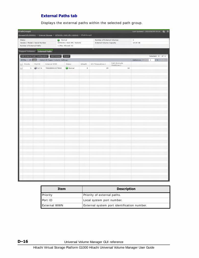
Hitachi Virtual Storage Platform G1000 Hitachi Universal Volume Manager User Guide
D–16 Universal Volume Manager GUI reference
External Paths tab
Displays the external paths within the selected path group.
Item Description
Priority Priority of external paths.
Port ID Local system port number.
External WWN External system port identification number.
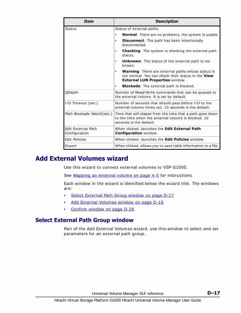
Universal Volume Manager GUI reference D–17Hitachi Virtual Storage Platform G1000 Hitachi Universal Volume Manager User Guide
Add External Volumes wizard Use this wizard to connect external volumes to VSP G1000.
See Mapping an external volume on page 4-5 for instructions.
Each window in the wizard is identified below the wizard title. The windows are:
• Select External Path Group window on page D-17
• Add External Volumes window on page D-19
• Confirm window on page D-26
Select External Path Group windowPart of the Add External Volumes wizard, use this window to select and set parameters for an external path group.
Status Status of external paths.
• Normal: There are no problems, the system is usable.
• Disconnect: The path has been intentionally disconnected.
• Checking: The system is checking the external path status.
• Unknown: The status of the external path is not known.
• Warning: There are external paths whose status is not normal. You can check their status in the View External LUN Properties window.
• Blockade: The external path is blocked.
QDepth Number of Read/Write commands that can be queued to the external volume. 8 is set by default.
I/O Timeout (sec.) Number of seconds that should pass before I/O to the external volume times out. 15 seconds is the default.
Path Blockade Watch(sec.) Time that will elapse from the time that a path goes down to the time when the external volume is blocked. 10 seconds is the default.
Edit External Path Configuration
When clicked, launches the Edit External Path Configuration window.
Edit Policies When clicked, launches the Edit Policies window.
Export When clicked, allows you to save table information to a file.
Item Description
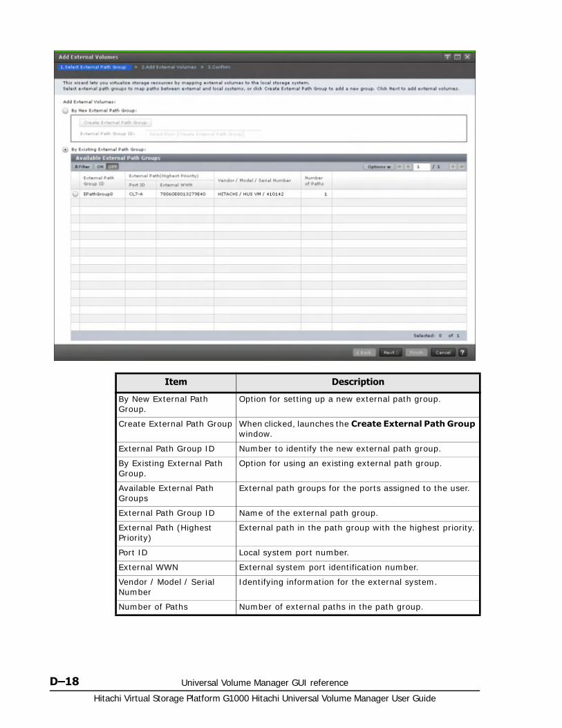
Hitachi Virtual Storage Platform G1000 Hitachi Universal Volume Manager User Guide
D–18 Universal Volume Manager GUI reference
Item Description
By New External Path Group.
Option for setting up a new external path group.
Create External Path Group When clicked, launches the Create External Path Group window.
External Path Group ID Number to identify the new external path group.
By Existing External Path Group.
Option for using an existing external path group.
Available External Path Groups
External path groups for the ports assigned to the user.
External Path Group ID Name of the external path group.
External Path (Highest Priority)
External path in the path group with the highest priority.
Port ID Local system port number.
External WWN External system port identification number.
Vendor / Model / Serial Number
Identifying information for the external system.
Number of Paths Number of external paths in the path group.
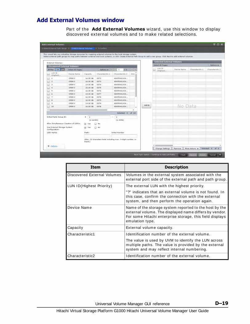
Universal Volume Manager GUI reference D–19Hitachi Virtual Storage Platform G1000 Hitachi Universal Volume Manager User Guide
Add External Volumes windowPart of the Add External Volumes wizard, use this window to display discovered external volumes and to make related selections.
Item Description
Discovered External Volumes Volumes in the external system associated with the external port side of the external path and path group.
LUN ID(Highest Priority) The external LUN with the highest priority.
"?" indicates that an external volume is not found. In this case, confirm the connection with the external system, and then perform the operation again.
Device Name Name of the storage system reported to the host by the external volume. The displayed name differs by vendor. For some Hitachi enterprise storage, this field displays emulation type.
Capacity External volume capacity.
Characteristic1 Identification number of the external volume.
The value is used by UVM to identify the LUN across multiple paths. The value is provided by the external system and may reflect internal numbering.
Characteristic2 Identification number of the external volume.
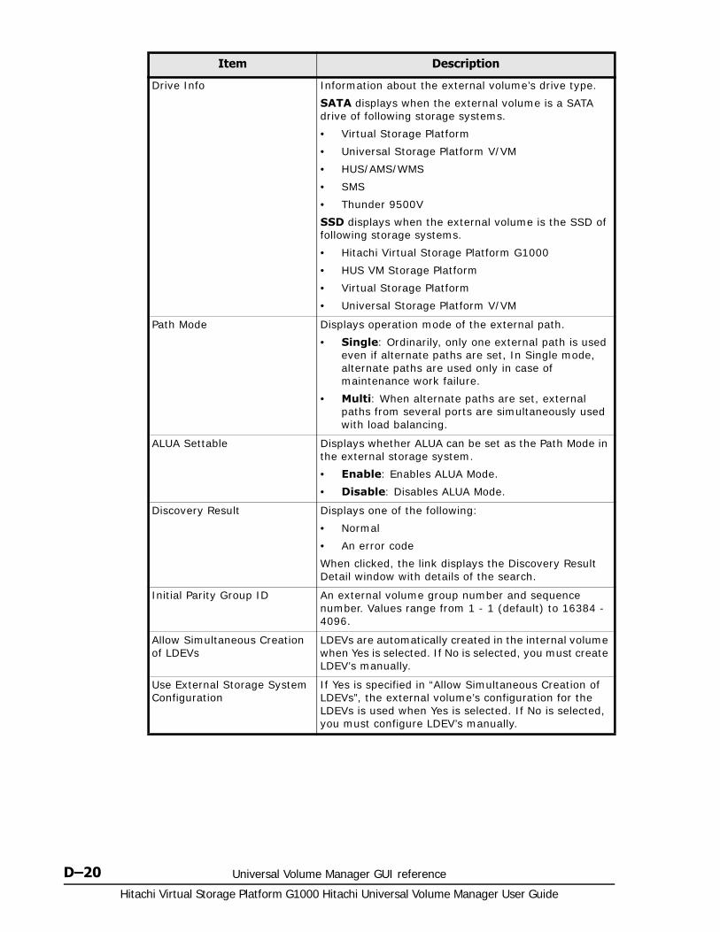
Hitachi Virtual Storage Platform G1000 Hitachi Universal Volume Manager User Guide
D–20 Universal Volume Manager GUI reference
Drive Info Information about the external volume’s drive type.
SATA displays when the external volume is a SATA drive of following storage systems.
• Virtual Storage Platform
• Universal Storage Platform V/VM
• HUS/AMS/WMS
• SMS
• Thunder 9500V
SSD displays when the external volume is the SSD of following storage systems.
• Hitachi Virtual Storage Platform G1000
• HUS VM Storage Platform
• Virtual Storage Platform
• Universal Storage Platform V/VM
Path Mode Displays operation mode of the external path.
• Single: Ordinarily, only one external path is used even if alternate paths are set, In Single mode, alternate paths are used only in case of maintenance work failure.
• Multi: When alternate paths are set, external paths from several ports are simultaneously used with load balancing.
ALUA Settable Displays whether ALUA can be set as the Path Mode in the external storage system.
• Enable: Enables ALUA Mode.
• Disable: Disables ALUA Mode.
Discovery Result Displays one of the following:
• Normal
• An error code
When clicked, the link displays the Discovery Result Detail window with details of the search.
Initial Parity Group ID An external volume group number and sequence number. Values range from 1 - 1 (default) to 16384 - 4096.
Allow Simultaneous Creation of LDEVs
LDEVs are automatically created in the internal volume when Yes is selected. If No is selected, you must create LDEV’s manually.
Use External Storage System Configuration
If Yes is specified in “Allow Simultaneous Creation of LDEVs”, the external volume’s configuration for the LDEVs is used when Yes is selected. If No is selected, you must configure LDEV’s manually.
Item Description
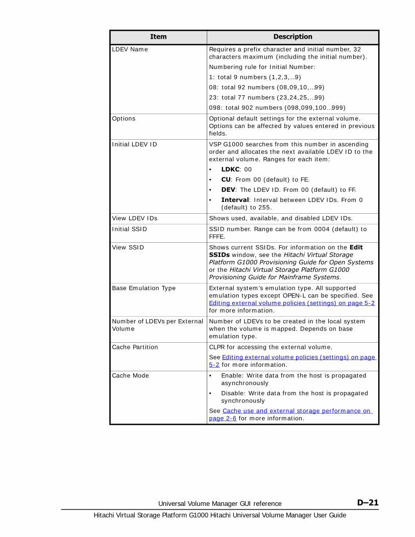
Universal Volume Manager GUI reference D–21Hitachi Virtual Storage Platform G1000 Hitachi Universal Volume Manager User Guide
LDEV Name Requires a prefix character and initial number, 32 characters maximum (including the initial number).
Numbering rule for Initial Number:
1: total 9 numbers (1,2,3,…9)
08: total 92 numbers (08,09,10,…99)
23: total 77 numbers (23,24,25,…99)
098: total 902 numbers (098,099,100…999)
Options Optional default settings for the external volume. Options can be affected by values entered in previous fields.
Initial LDEV ID VSP G1000 searches from this number in ascending order and allocates the next available LDEV ID to the external volume. Ranges for each item:
• LDKC: 00
• CU: From 00 (default) to FE.
• DEV: The LDEV ID. From 00 (default) to FF.
• Interval: Interval between LDEV IDs. From 0 (default) to 255.
View LDEV IDs Shows used, available, and disabled LDEV IDs.
Initial SSID SSID number. Range can be from 0004 (default) to FFFE.
View SSID Shows current SSIDs. For information on the Edit SSIDs window, see the Hitachi Virtual Storage Platform G1000 Provisioning Guide for Open Systems or the Hitachi Virtual Storage Platform G1000 Provisioning Guide for Mainframe Systems.
Base Emulation Type External system’s emulation type. All supported emulation types except OPEN-L can be specified. See Editing external volume policies (settings) on page 5-2 for more information.
Number of LDEVs per External Volume
Number of LDEVs to be created in the local system when the volume is mapped. Depends on base emulation type.
Cache Partition CLPR for accessing the external volume.
See Editing external volume policies (settings) on page 5-2 for more information.
Cache Mode • Enable: Write data from the host is propagated asynchronously
• Disable: Write data from the host is propagated synchronously
See Cache use and external storage performance on page 2-6 for more information.
Item Description

Hitachi Virtual Storage Platform G1000 Hitachi Universal Volume Manager User Guide
D–22 Universal Volume Manager GUI reference
Selected External Volumes
Displays selected external volumes.
Inflow Control • Enable: Limits or prevents write data from being written to cache memory when the write operation cannot be performed.
• Disable: Allows write data to be written to cache when the write operation cannot be performed.
See Editing external volume policies (settings) on page 5-2 for more information.
Use ALUA as Path Mode Select whether ALUA is used as the Path Mode. The default is Enable if ALUA mode can be set as the Path Mode. Otherwise, the default is Disable.
• Enable: Enables ALUA mode.
• Disable: Disables ALUA mode.
Load Balance Mode Select I/O load balance system for external storage system.
• Depend on the selected external volume(s): If Enable is set for ALUA Settable on the external volume, Normal Round-robin is set for Load Balance Mode automatically. If Disable is set for ALUA Settable, Disable is set for Load Balance Mode automatically.
• Normal Round-robin: Performs load balance in round-robin system.
• Extended Round-robin: Load balance system is automatically switched for sequential I/O and random I/O.
• Disable: Performs I/O operation with a single path, without load balance.
The default is the value set in the Edit Policies window.
If the product name of an external storage system is displayed as "(generic)", Depend on the selected external volume(s) is used by default.
This item cannot be selected when the path mode of the external volume is Single or Disable is selected for Use ALUA as Path Mode.
MP Blade MP blade for the external volume.
• Range is from MPB0 to MPB7.
• Auto (default): Blade is automatically selected by the system.
• Blade with lowest number is used when Auto cannot be selected.
Add When clicked, moves selected volumes to the Selected External Volumes list.
Item Description
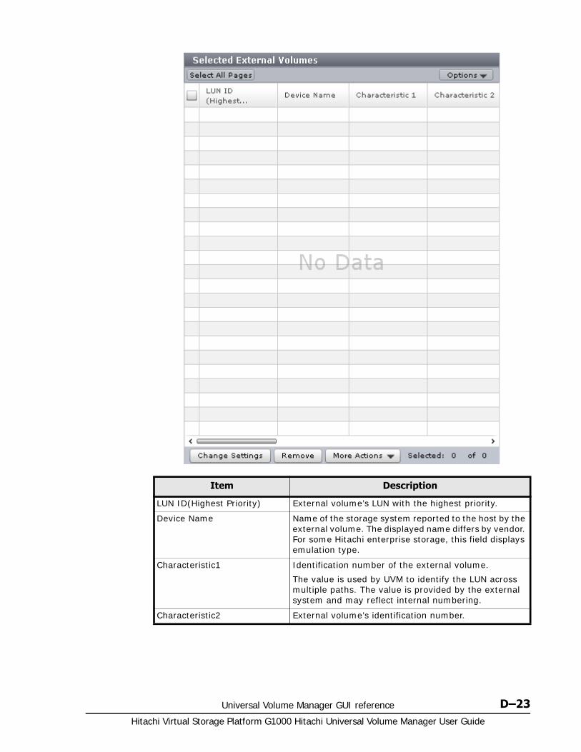
Universal Volume Manager GUI reference D–23Hitachi Virtual Storage Platform G1000 Hitachi Universal Volume Manager User Guide
Item Description
LUN ID(Highest Priority) External volume’s LUN with the highest priority.
Device Name Name of the storage system reported to the host by the external volume. The displayed name differs by vendor. For some Hitachi enterprise storage, this field displays emulation type.
Characteristic1 Identification number of the external volume.
The value is used by UVM to identify the LUN across multiple paths. The value is provided by the external system and may reflect internal numbering.
Characteristic2 External volume’s identification number.
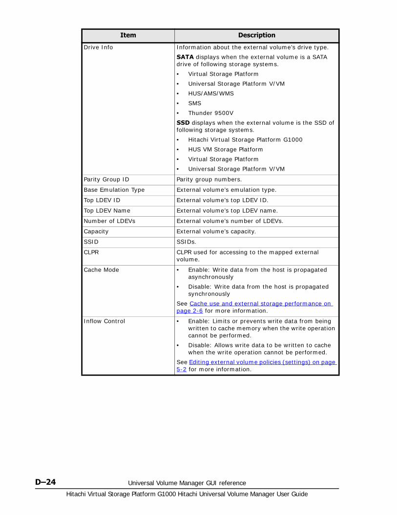
Hitachi Virtual Storage Platform G1000 Hitachi Universal Volume Manager User Guide
D–24 Universal Volume Manager GUI reference
Drive Info Information about the external volume’s drive type.
SATA displays when the external volume is a SATA drive of following storage systems.
• Virtual Storage Platform
• Universal Storage Platform V/VM
• HUS/AMS/WMS
• SMS
• Thunder 9500V
SSD displays when the external volume is the SSD of following storage systems.
• Hitachi Virtual Storage Platform G1000
• HUS VM Storage Platform
• Virtual Storage Platform
• Universal Storage Platform V/VM
Parity Group ID Parity group numbers.
Base Emulation Type External volume’s emulation type.
Top LDEV ID External volume’s top LDEV ID.
Top LDEV Name External volume’s top LDEV name.
Number of LDEVs External volume’s number of LDEVs.
Capacity External volume’s capacity.
SSID SSIDs.
CLPR CLPR used for accessing to the mapped external volume.
Cache Mode • Enable: Write data from the host is propagated asynchronously
• Disable: Write data from the host is propagated synchronously
See Cache use and external storage performance on page 2-6 for more information.
Inflow Control • Enable: Limits or prevents write data from being written to cache memory when the write operation cannot be performed.
• Disable: Allows write data to be written to cache when the write operation cannot be performed.
See Editing external volume policies (settings) on page 5-2 for more information.
Item Description
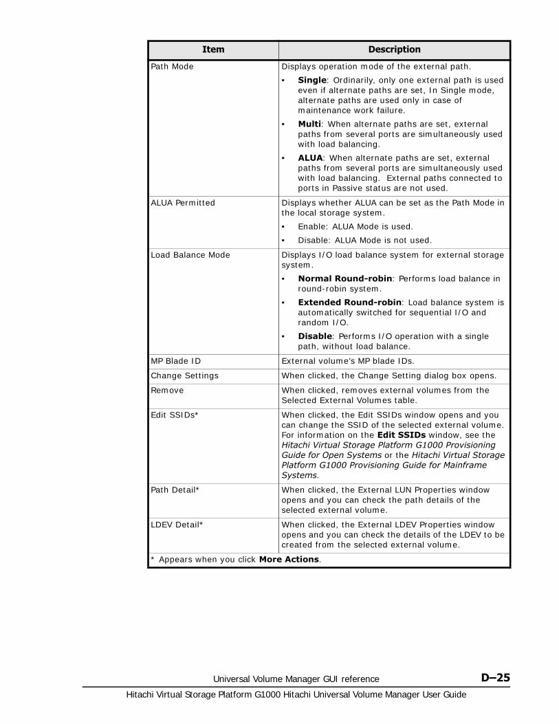
Universal Volume Manager GUI reference D–25Hitachi Virtual Storage Platform G1000 Hitachi Universal Volume Manager User Guide
Path Mode Displays operation mode of the external path.
• Single: Ordinarily, only one external path is used even if alternate paths are set, In Single mode, alternate paths are used only in case of maintenance work failure.
• Multi: When alternate paths are set, external paths from several ports are simultaneously used with load balancing.
• ALUA: When alternate paths are set, external paths from several ports are simultaneously used with load balancing. External paths connected to ports in Passive status are not used.
ALUA Permitted Displays whether ALUA can be set as the Path Mode in the local storage system.
• Enable: ALUA Mode is used.
• Disable: ALUA Mode is not used.
Load Balance Mode Displays I/O load balance system for external storage system.
• Normal Round-robin: Performs load balance in round-robin system.
• Extended Round-robin: Load balance system is automatically switched for sequential I/O and random I/O.
• Disable: Performs I/O operation with a single path, without load balance.
MP Blade ID External volume’s MP blade IDs.
Change Settings When clicked, the Change Setting dialog box opens.
Remove When clicked, removes external volumes from the Selected External Volumes table.
Edit SSIDs* When clicked, the Edit SSIDs window opens and you can change the SSID of the selected external volume. For information on the Edit SSIDs window, see the Hitachi Virtual Storage Platform G1000 Provisioning Guide for Open Systems or the Hitachi Virtual Storage Platform G1000 Provisioning Guide for Mainframe Systems.
Path Detail* When clicked, the External LUN Properties window opens and you can check the path details of the selected external volume.
LDEV Detail* When clicked, the External LDEV Properties window opens and you can check the details of the LDEV to be created from the selected external volume.
* Appears when you click More Actions.
Item Description

Hitachi Virtual Storage Platform G1000 Hitachi Universal Volume Manager User Guide
D–26 Universal Volume Manager GUI reference
Confirm window
Item Description
Task Name Identifies the operation within the system when Apply is clicked. Allows you to track the status of the operation.
External Path Group ID Name of the external path group.
Vendor / Model / Serial Number
Identifying information for the external system.
Priority Priority of external paths.
Port ID Local system port number.
External WWN External system port identification number.
LUN ID(Highest Priority) The LUN which is connected to the external path with the highest priority.
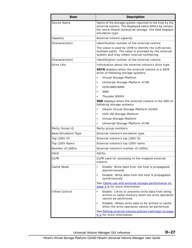
Universal Volume Manager GUI reference D–27Hitachi Virtual Storage Platform G1000 Hitachi Universal Volume Manager User Guide
Device Name Name of the storage system reported to the host by the external volume. The displayed name differs by vendor. For some Hitachi enterprise storage, this field displays emulation type.
Capacity External volume capacity.
Characteristic1 Identification number of the external volume.
The value is used by UVM to identify the LUN across multiple paths. The value is provided by the external system and may reflect internal numbering.
Characteristic2 Identification number of the external volume.
Drive Info Information about the external volume’s drive type.
SATA displays when the external volume is a SATA drive of following storage systems.
• Virtual Storage Platform
• Universal Storage Platform V/VM
• HUS/AMS/WMS
• SMS
• Thunder 9500V
SSD displays when the external volume is the SSD of following storage systems.
• Hitachi Virtual Storage Platform G1000
• HUS VM Storage Platform
• Virtual Storage Platform
• Universal Storage Platform V/VM
Parity Group ID Parity group numbers.
Base Emulation Type External volume’s emulation type.
Top LDEV ID External volume’s top LDEV ID.
Top LDEV Name External volume’s top LDEV name.
Number of LDEVs External volume’s number of LDEVs.
SSID SSIDs.
CLPR CLPR used for accessing to the mapped external volume.
Cache Mode • Enable: Write data from the host is propagated asynchronously
• Disable: Write data from the host is propagated synchronously
See Cache use and external storage performance on page 2-6 for more information.
Inflow Control • Enable: Limits or prevents write data from being written to cache memory when the write operation cannot be performed.
• Disable: Allows write data to be written to cache when the write operation cannot be performed.
See Editing external volume policies (settings) on page 5-2 for more information.
Item Description
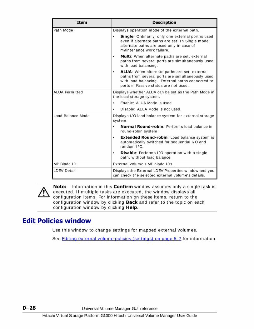
Hitachi Virtual Storage Platform G1000 Hitachi Universal Volume Manager User Guide
D–28 Universal Volume Manager GUI reference
Edit Policies windowUse this window to change settings for mapped external volumes.
See Editing external volume policies (settings) on page 5-2 for information.
Path Mode Displays operation mode of the external path.
• Single: Ordinarily, only one external port is used even if alternate paths are set. In Single mode, alternate paths are used only in case of maintenance work failure.
• Multi: When alternate paths are set, external paths from several ports are simultaneously used with load balancing.
• ALUA: When alternate paths are set, external paths from several ports are simultaneously used with load balancing. External paths connected to ports in Passive status are not used.
ALUA Permitted Displays whether ALUA can be set as the Path Mode in the local storage system.
• Enable: ALUA Mode is used.
• Disable: ALUA Mode is not used.
Load Balance Mode Displays I/O load balance system for external storage system.
• Normal Round-robin: Performs load balance in round-robin system.
• Extended Round-robin: Load balance system is automatically switched for sequential I/O and random I/O.
• Disable: Performs I/O operation with a single path, without load balance.
MP Blade ID External volume’s MP blade IDs.
LDEV Detail Displays the External LDEV Properties window and you can check the selected external volume's details.
Note: Information in this Confirm window assumes only a single task is executed. If multiple tasks are executed, the window displays all configuration items. For information on these items, return to the configuration window by clicking Back and refer to the topic on each configuration window by clicking Help.
Item Description
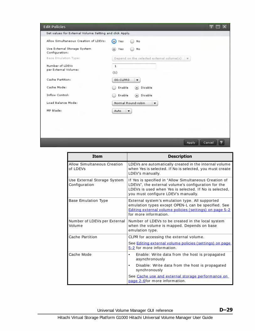
Universal Volume Manager GUI reference D–29Hitachi Virtual Storage Platform G1000 Hitachi Universal Volume Manager User Guide
Item Description
Allow Simultaneous Creation of LDEVs
LDEVs are automatically created in the internal volume when Yes is selected. If No is selected, you must create LDEV’s manually.
Use External Storage System Configuration
If Yes is specified in “Allow Simultaneous Creation of LDEVs”, the external volume’s configuration for the LDEVs is used when Yes is selected. If No is selected, you must configure LDEV’s manually.
Base Emulation Type External system’s emulation type. All supported emulation types except OPEN-L can be specified. See Editing external volume policies (settings) on page 5-2 for more information.
Number of LDEVs per External Volume
Number of LDEVs to be created in the local system when the volume is mapped. Depends on base emulation type.
Cache Partition CLPR for accessing the external volume.
See Editing external volume policies (settings) on page 5-2 for more information.
Cache Mode • Enable: Write data from the host is propagated asynchronously
• Disable: Write data from the host is propagated synchronously
See Cache use and external storage performance on page 2-6for more information.
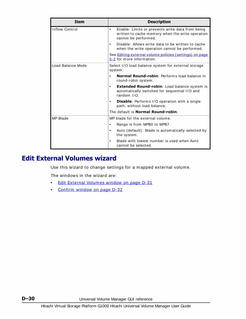
Hitachi Virtual Storage Platform G1000 Hitachi Universal Volume Manager User Guide
D–30 Universal Volume Manager GUI reference
Edit External Volumes wizardUse this wizard to change settings for a mapped external volume.
The windows in the wizard are:
• Edit External Volumes window on page D-31
• Confirm window on page D-32
Inflow Control • Enable: Limits or prevents write data from being written to cache memory when the write operation cannot be performed.
• Disable: Allows write data to be written to cache when the write operation cannot be performed.
See Editing external volume policies (settings) on page 5-2 for more information.
Load Balance Mode Select I/O load balance system for external storage system.
• Normal Round-robin: Performs load balance in round-robin system.
• Extended Round-robin: Load balance system is automatically switched for sequential I/O and random I/O.
• Disable: Performs I/O operation with a single path, without load balance.
The default is Normal Round-robin.
MP Blade MP blade for the external volume.
• Range is from MPB0 to MPB7.
• Auto (default): Blade is automatically selected by the system.
• Blade with lowest number is used when Auto cannot be selected.
Item Description

Universal Volume Manager GUI reference D–31Hitachi Virtual Storage Platform G1000 Hitachi Universal Volume Manager User Guide
Edit External Volumes window
Item Description
Cache Mode • Enable: Write data from the host is propagated asynchronously.
• Disable: Write data from the host is propagated synchronously.
See Cache use and external storage performance on page 2-6 for more information.
Inflow Control • Enable: Limits or prevents write data from being written to cache memory when the write operation cannot be performed.
• Disable: Allows write data to be written to cache when the write operation cannot be performed.
See Editing external volume policies (settings) on page 5-2 for more information.
Use ALUA as Path Mode Select whether ALUA is used as the Path Mode..
• Enable: Enables ALUA mode.
• Disable: Disables ALUA mode.
The value that is set for the selected external volume is used as the default. If two or more external volumes with different values are selected, the item is placed in non-selected status. If the ALUA mode cannot be set for the selected external volume, Enable cannot be selected.

Hitachi Virtual Storage Platform G1000 Hitachi Universal Volume Manager User Guide
D–32 Universal Volume Manager GUI reference
Confirm window
Load Balance Mode Select I/O load balance system for external storage system.
• Normal Round-robin: Performs load balance in round-robin system.
• Extended Round-robin: Load balance system is automatically switched for sequential I/O and random I/O.
• Disable: Performs I/O operation with a single path, without load balance.
The value that is set for the selected external volume is used as the default. If two or more external volumes with different values are selected, the item is placed in non-selected status.
Item Description
Parity Group ID Displays parity group numbers.
Top LDEV ID External volume’s top LDEV ID.
Top LDEV Name External volume’s top LDEV name.
Item Description

Universal Volume Manager GUI reference D–33Hitachi Virtual Storage Platform G1000 Hitachi Universal Volume Manager User Guide
Cache Mode • Enable: Write data from the host is propagated asynchronously
• Disable: Write data from the host is propagated synchronously
When nondisruptive migration is specified as the Attribute, the cache modes are displayed.
• Through: Transfers write and read requests from the host to the external storage system. The local system’s cache is not used.
• Write Sync: Reflects write data from the host to the external storage system synchronously. If read or write is performed while data is being written to the external storage system, the read or write operation waits until the ongoing write operation is completed.
While cache mode operations are in progress, status is reported for cache mode changes.
• (Changing): Transition to the displayed cache mode is in progress.
• (Error): Transition to the displayed cache mode has failed and maintenance work is required.
See Cache use and external storage performance on page 2-6for more information.
Inflow Control • Enable: Limits or prevents write data from being written to cache memory when the write operation cannot be performed.
• Disable: Allows write data to be written to cache when the write operation cannot be performed.
See Editing external volume policies (settings) on page 5-2 for more information.
Path Mode Displays the external path of the external volume.
• Single: One external path is used, with alternate paths available in case of failure.
• Multi: Multiple paths are used at the same time.
• ALUA: Like Multi, all paths are used; however, they are not used when connected to ports in Passive status. For more information, see External paths on page 2-14.
ALUA Permitted Displays whether ALUA can be set as the Path Mode in the local storage system.
• Enable: ALUA Mode is used.
• Disable: ALUA Mode is not used.
Item Description
Hitachi Virtual Storage Platform G1000 Hitachi Universal Volume Manager User Guide
D–34 Universal Volume Manager GUI reference
Edit External Path Configuration wizardUse this wizard to add and remove external paths to a path group, and to raise and lower path priority.
See Adding an external path to an existing path group on page 5-11 for instructions.
The windows in the wizard are:
• Edit External Path Configuration window on page D-35
• Confirm window on page D-37
Load Balance Mode Displays I/O load balance system for external storage system.
• Normal Round-robin: Performs load balance in round-robin system.
• Extended Round-robin: Load balance system is automatically switched for sequential I/O and random I/O.
• Disable: Performs I/O operation with a single path, without load balance.
Item Description

Universal Volume Manager GUI reference D–35Hitachi Virtual Storage Platform G1000 Hitachi Universal Volume Manager User Guide
Edit External Path Configuration window
Only the external paths that are connected with the port assigned to the user are displayed.
The following figure shows the Selected External Paths pane of the Edit External Path Configuration window.
Item Description
External Path Group ID Name of the external path group.
External Paths External path information.
Discover External Target Ports When clicked, opens the Discover External Target Ports window, which lists available external ports.
External Storage System The external system selected (greyed out). If no system was selected, allows you to select the system from a list.
Available External Paths
Port ID Local system port number.
External WWN External system port identification number.
Add When clicked, moves selected paths to the Selected External Paths list.

Hitachi Virtual Storage Platform G1000 Hitachi Universal Volume Manager User Guide
D–36 Universal Volume Manager GUI reference
The following table provides descriptions of items in the Selected External Paths pane of the Edit External Path Configuration window.
Item Description
Selected External Paths (see preceding figure)
Remove When clicked, removes the selected path from the Selected External Paths list.
Priority Priority of external paths.
Port ID Local system port number.
External WWN External system port identification number.
Raise Priority Raise the priority of the selected external path.
Lower Priority Lower the priority of the selected external path.

Universal Volume Manager GUI reference D–37Hitachi Virtual Storage Platform G1000 Hitachi Universal Volume Manager User Guide
Confirm window
Edit External WWNs wizardUse this wizard to change the external system’s WWN port setting.
See Editing external WWN settings on page 5-9 for instructions.
The windows in the wizard are:
• Edit External WWNs window on page D-38
• Confirm window on page D-39
Item Description
Task Name Identifies the operation within the system when Apply is clicked. Allows you to track the status of the operation.
External Path Group ID Displays the name of the external path group.
Vendor / Model / Serial Number
Identifying information for the external system.
Priority Priority of external paths.
Port ID Local system port number.
External WWN External system port identification number.

Hitachi Virtual Storage Platform G1000 Hitachi Universal Volume Manager User Guide
D–38 Universal Volume Manager GUI reference
Edit External WWNs window
Item Description
QDepth Number of Read/Write commands that can be queued to the external volume. The numbers 2 through 128 can be entered. When two or more external paths with different values are selected, the field is blank.
I/O Timeout (sec.) Number of seconds that should pass before I/O to the external volume times out. The numbers 5 through 240 can be entered. When two or more external paths with different values are selected, the field is blank.
Path Blockade Watch (sec.) Time that elapses from the time that a path goes down to the time when the external volume is blocked. The numbers 5 through 180 can be entered. When two or more external paths with different values are selected, the field is blank.
Caution: If you want to change multiple parameters for an external WWN more than once, wait until the currently applied task finishes, and then perform the next setting change.
If you make a setting change for the next task before completing the last, the setting will be applied to the next task only. The result might be different from what you expected.

Universal Volume Manager GUI reference D–39Hitachi Virtual Storage Platform G1000 Hitachi Universal Volume Manager User Guide
Confirm window
Delete External Volumes wizardUse this wizard to delete external volume mapping.
See Deleting an external volume mapping on page 5-28 for instructions.
The windows in the wizard are:
• Delete External Volumes window on page D-40
• Confirm window on page D-41
Item Description
Port ID Local system port number.
External WWN External system port identification number.
QDepth Number of Read/Write commands that can be queued to the external volume.
I/O Timeout (sec.) Number of seconds that should pass before I/O to the external volume times out.
Path Blockade Watch(sec.) Time that will elapse from the time that a path goes down to the time when the external volume is blocked.
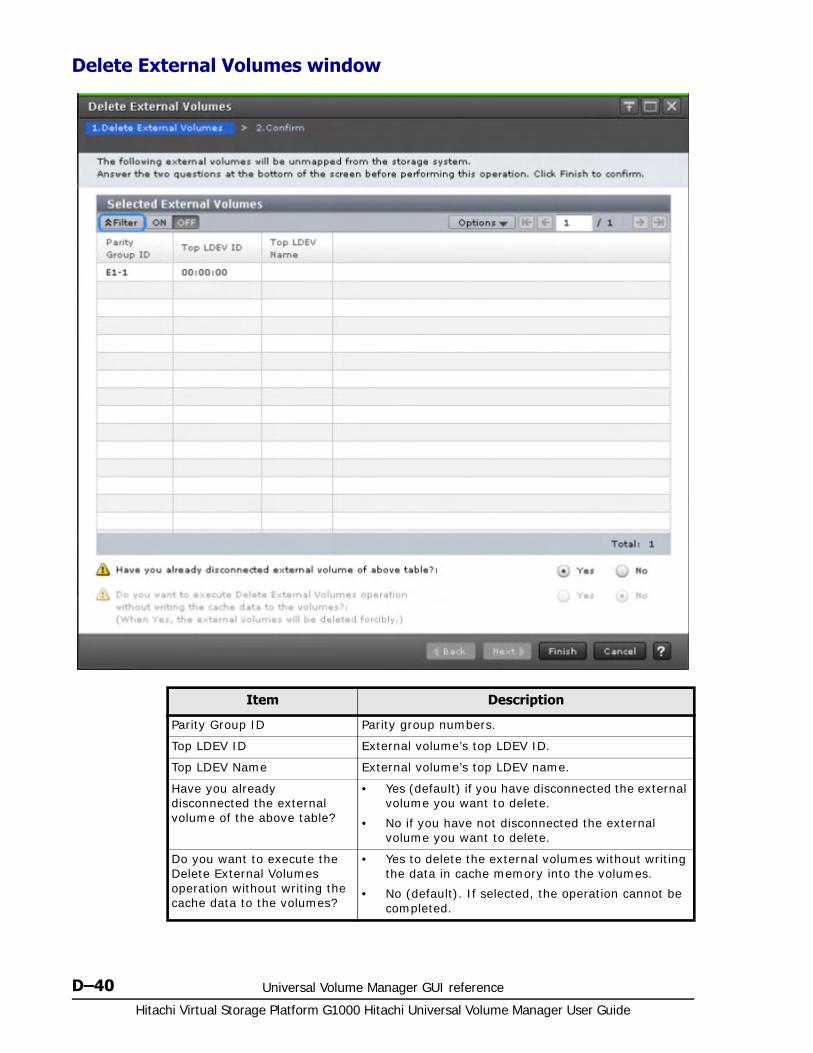
Hitachi Virtual Storage Platform G1000 Hitachi Universal Volume Manager User Guide
D–40 Universal Volume Manager GUI reference
Delete External Volumes window
Item Description
Parity Group ID Parity group numbers.
Top LDEV ID External volume’s top LDEV ID.
Top LDEV Name External volume’s top LDEV name.
Have you already disconnected the external volume of the above table?
• Yes (default) if you have disconnected the external volume you want to delete.
• No if you have not disconnected the external volume you want to delete.
Do you want to execute the Delete External Volumes operation without writing the cache data to the volumes?
• Yes to delete the external volumes without writing the data in cache memory into the volumes.
• No (default). If selected, the operation cannot be completed.
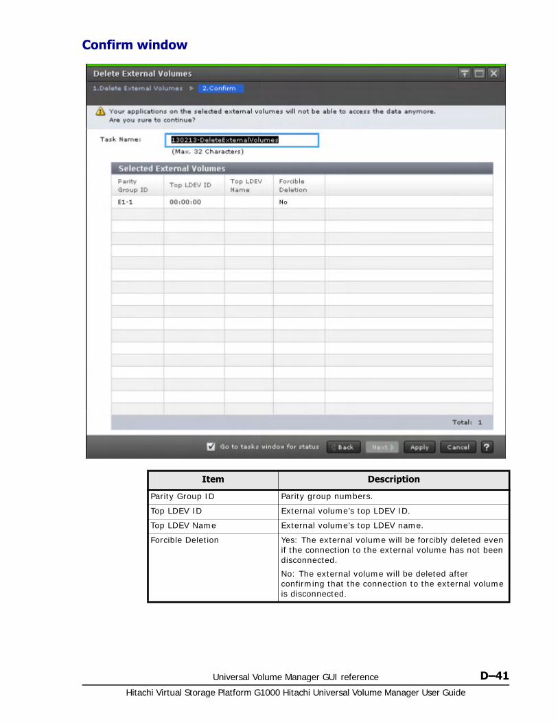
Universal Volume Manager GUI reference D–41Hitachi Virtual Storage Platform G1000 Hitachi Universal Volume Manager User Guide
Confirm window
Item Description
Parity Group ID Parity group numbers.
Top LDEV ID External volume’s top LDEV ID.
Top LDEV Name External volume’s top LDEV name.
Forcible Deletion Yes: The external volume will be forcibly deleted even if the connection to the external volume has not been disconnected.
No: The external volume will be deleted after confirming that the connection to the external volume is disconnected.
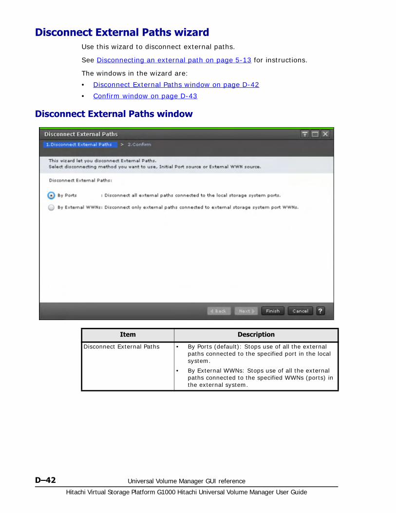
Hitachi Virtual Storage Platform G1000 Hitachi Universal Volume Manager User Guide
D–42 Universal Volume Manager GUI reference
Disconnect External Paths wizardUse this wizard to disconnect external paths.
See Disconnecting an external path on page 5-13 for instructions.
The windows in the wizard are:
• Disconnect External Paths window on page D-42
• Confirm window on page D-43
Disconnect External Paths window
Item Description
Disconnect External Paths • By Ports (default): Stops use of all the external paths connected to the specified port in the local system.
• By External WWNs: Stops use of all the external paths connected to the specified WWNs (ports) in the external system.

Universal Volume Manager GUI reference D–43Hitachi Virtual Storage Platform G1000 Hitachi Universal Volume Manager User Guide
Confirm window
Reconnect External Paths wizardUse this wizard to reconnect external paths.
See Reconnecting an external path on page 5-14 for instructions.
The windows in the wizard are:
• Reconnect External Paths window on page D-44
• Confirm window on page D-45
Item Description
Port ID Local system port number.
External WWN External system port identification number.
Vendor / Model / Serial Number
Identifying information for the external system.

Hitachi Virtual Storage Platform G1000 Hitachi Universal Volume Manager User Guide
D–44 Universal Volume Manager GUI reference
Reconnect External Paths window
Item Description
Reconnect External Paths • By Ports (default): Reconnects all external paths connected to the specified port in the local system.
• By External WWNs: Reconnects all external paths connected to the specified WWNs (ports) in the external system.

Universal Volume Manager GUI reference D–45Hitachi Virtual Storage Platform G1000 Hitachi Universal Volume Manager User Guide
Confirm window
Selected External Paths table
Discover External Target Ports windowUse this window to add or remove external ports for the external path.
This window is used in the following operations:
• Mapping an external volume on page 4-5
• Adding an external path to an existing path group on page 5-11
Item Description
Port ID Local system port number.
External WWN External system port identification number.
Vendor / Model / Serial Number
Identifying information for the external system.

Hitachi Virtual Storage Platform G1000 Hitachi Universal Volume Manager User Guide
D–46 Universal Volume Manager GUI reference
Only external ports assigned to the user display.
Create External Path Group windowUse this window to create a new external path group.
This window is used in the operation, Mapping an external volume on page 4-5.
Item Description
Available External Ports
Port ID Port number in the local system connecting to the external system.
Add When clicked, moves selected paths to the Selected External Ports list.
Selected External Paths
Remove When clicked, removes the selected path from the Selected External Ports list.
Port ID External system port number used in the external path.

Universal Volume Manager GUI reference D–47Hitachi Virtual Storage Platform G1000 Hitachi Universal Volume Manager User Guide
Only paths with ports assigned to the user can display.
The following figure shows the Selected External Paths pane of the Create External Path Group window.
Item Description
Initial External Path Group ID An initial ID for the path group. The storage system searches IDs in ascending order from this value and allocates an ID that can be used. The range can be from 0 to 63,231. 0 is the default.
Discover External Target Ports When clicked, opens the Discover External Target Ports window.
External Storage System The external system selected (greyed out). If no system was selected, allows you to select the system from a list.
Available External Paths
Port ID Local system port number.
External WWN External system port identification number.
Add When clicked, moves selected paths to the Selected External Paths list.
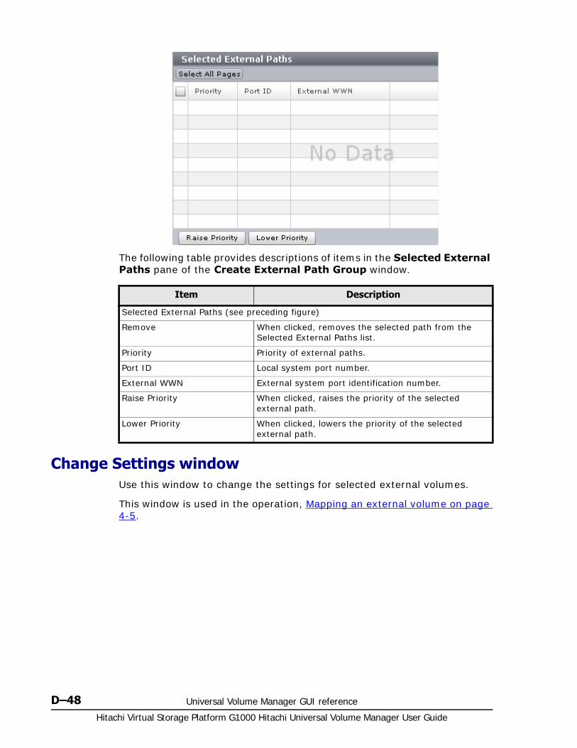
Hitachi Virtual Storage Platform G1000 Hitachi Universal Volume Manager User Guide
D–48 Universal Volume Manager GUI reference
The following table provides descriptions of items in the Selected External Paths pane of the Create External Path Group window.
Change Settings windowUse this window to change the settings for selected external volumes.
This window is used in the operation, Mapping an external volume on page 4-5.
Item Description
Selected External Paths (see preceding figure)
Remove When clicked, removes the selected path from the Selected External Paths list.
Priority Priority of external paths.
Port ID Local system port number.
External WWN External system port identification number.
Raise Priority When clicked, raises the priority of the selected external path.
Lower Priority When clicked, lowers the priority of the selected external path.

Universal Volume Manager GUI reference D–49Hitachi Virtual Storage Platform G1000 Hitachi Universal Volume Manager User Guide
Item Description
Initial Parity Group ID An external volume group number and sequence number. Values range from 1 - 1 to 16384 - 4096. When two or more volumes with different values are selected, blank displays.
MP Blade • Range is from MPB0 to MPB7.
• Auto (default): Blade is automatically selected by the system, if available.
• Blade with lowest number is used when Auto cannot be selected.
• When two or more volumes with different values are selected, blank displays.
LDEV Settings If changes to LDEV settings are made, box must be checked to proceed.
LDEV ID LDEV IDs allocated to the external volume.
LDEV Name LDEV names.
Parity Group ID Parity group numbers.
Emulation Type LDEV emulation type.
Capacity LDEV capacity.
SSID SSIDs.
Resource Group Name (ID) Name and ID of the resource group for the LDEV. ID is enclosed in parentheses.

Hitachi Virtual Storage Platform G1000 Hitachi Universal Volume Manager User Guide
D–50 Universal Volume Manager GUI reference
View External LUN Properties windowUse this window to view settings and other details about external LUNs.
Virtual Storage Machine Model and serial number of the virtual storage machine for the LDEV.
Change LDEV Settings When clicked, opens Change LDEV Settings window.
Item Description
Item Description
Parity Group ID
Parity group numbers.
Priority Priority of external paths.
Port ID Local system port number.
External WWN External system port identification number.
LUN ID When the external path is connected to the selected external volume, the LUN ID displays.
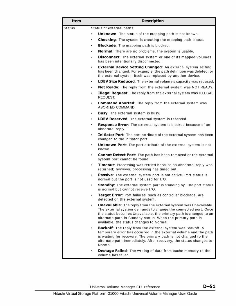
Universal Volume Manager GUI reference D–51Hitachi Virtual Storage Platform G1000 Hitachi Universal Volume Manager User Guide
Status Status of external paths.
• Unknown: The status of the mapping path is not known.
• Checking: The system is checking the mapping path status.
• Blockade: The mapping path is blocked.
• Normal: There are no problems, the system is usable.
• Disconnect: The external system or one of its mapped volumes has been intentionally disconnected.
• External Device Setting Changed: An external system setting has been changed. For example, the path definition was deleted, or the external system itself was replaced by another device.
• LDEV Size Reduced: The external volume’s capacity was reduced.
• Not Ready: The reply from the external system was NOT READY.
• Illegal Request: The reply from the external system was ILLEGAL REQUEST.
• Command Aborted: The reply from the external system was ABORTED COMMAND.
• Busy: The external system is busy.
• LDEV Reserved: The external system is reserved.
• Response Error: The external system is blocked because of an abnormal reply.
• Initiator Port: The port attribute of the external system has been changed to the initiator port.
• Unknown Port: The port attribute of the external system is not known.
• Cannot Detect Port: The path has been removed or the external system port cannot be found.
• Timeout: Processing was retried because an abnormal reply was returned; however, processing has timed out.
• Passive: The external system port is not active. Port status is normal but the port is not used for I/O.
• Standby: The external system port is standing by. The port status is normal but cannot receive I/O.
• Target Error: Port failures, such as controller blockade, are detected on the external system.
• Unavailable: The reply from the external system was Unavailable. The external system demands to change the connected port. Once the status becomes Unavailable, the primary path is changed to an alternate path in Standby status. When the primary path is available, the status changes to Normal.
• Backoff: The reply from the external system was Backoff. A temporary error has occurred in the external volume and the path is waiting for recovery. The primary path is not changed to the alternate path immediately. After recovery, the status changes to Normal.
• Destage Failed: The writing of data from cache memory to the volume has failed.
Item Description

Hitachi Virtual Storage Platform G1000 Hitachi Universal Volume Manager User Guide
D–52 Universal Volume Manager GUI reference
Reconnect External Storage Systems windowUse this window to reconnect the external storage system.
See Reconnecting an external storage system, all mapped volumes on page 5-25 for instructions.
Target Port Asymmetric Access State
When the path mode is ALUA, the port state of the external storage system displays.
• Active/Optimized: The performance is in a good state.
• Active/Non-Optimized: Data can be sent and received, but the performance is inferior to Active/Optimized.
A space displays in one of the following cases:
• The path mode is other than ALUA.
• Mapping of an external volume is not completed.
Item Description
Item Description
Parity Group ID Parity group numbers.
Top LDEV ID External volume’s top LDEV ID. Blank displays when an LDEV is not created.
Top LDEV Name External volume’s top LDEV name. Blank displays when an LDEV is not created.
Vendor / Model / Serial Number
Identifying information for the external system.

Universal Volume Manager GUI reference D–53Hitachi Virtual Storage Platform G1000 Hitachi Universal Volume Manager User Guide
Reconnect External Volumes windowUse this window to reconnect the external volume.
See Reconnecting a single mapped volume on page 5-26 for instructions.
Disconnect External Storage Systems windowUse this window to disconnect the storage system
See Disconnecting an external storage system, all mapped volumes on page 5-20 for instructions.
Item Description
Parity Group ID Parity group numbers.
Top LDEV ID External volume’s top LDEV ID. Blank displays when an LDEV is not created.
Top LDEV Name External volume’s top LDEV name. Blank displays when an LDEV is not created.
Vendor / Model / Serial Number
Identifying information for the external system.

Hitachi Virtual Storage Platform G1000 Hitachi Universal Volume Manager User Guide
D–54 Universal Volume Manager GUI reference
Disconnect External Volumes windowUse this window to disconnect an external volume.
See Disconnecting a single mapped volume on page 5-21 for instructions.
Item Description
Parity Group ID Parity group numbers.
Top LDEV ID External volume’s top LDEV ID. Blank displays when an LDEV is not created.
Top LDEV Name External volume’s top LDEV name. Blank displays when an LDEV is not created.
Vendor / Model / Serial Number
Identifying information for the external system.
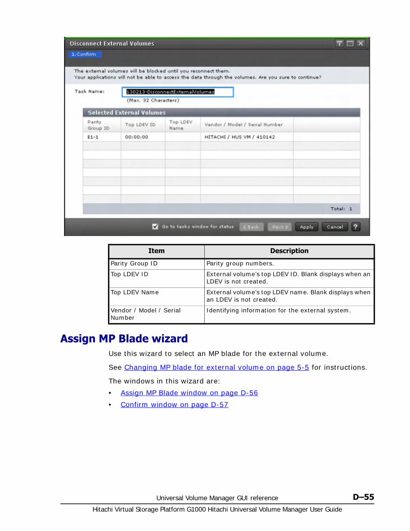
Universal Volume Manager GUI reference D–55Hitachi Virtual Storage Platform G1000 Hitachi Universal Volume Manager User Guide
Assign MP Blade wizardUse this wizard to select an MP blade for the external volume.
See Changing MP blade for external volume on page 5-5 for instructions.
The windows in this wizard are:
• Assign MP Blade window on page D-56
• Confirm window on page D-57
Item Description
Parity Group ID Parity group numbers.
Top LDEV ID External volume’s top LDEV ID. Blank displays when an LDEV is not created.
Top LDEV Name External volume’s top LDEV name. Blank displays when an LDEV is not created.
Vendor / Model / Serial Number
Identifying information for the external system.
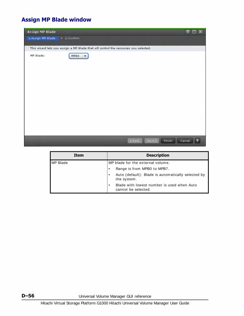
Hitachi Virtual Storage Platform G1000 Hitachi Universal Volume Manager User Guide
D–56 Universal Volume Manager GUI reference
Assign MP Blade window
Item Description
MP Blade MP blade for the external volume.
• Range is from MPB0 to MPB7.
• Auto (default): Blade is automatically selected by the system.
• Blade with lowest number is used when Auto cannot be selected.

Universal Volume Manager GUI reference D–57Hitachi Virtual Storage Platform G1000 Hitachi Universal Volume Manager User Guide
Confirm window
External LDEV Properties windowUse this window to view settings for external LDEVs.
Item Description
Parity Group ID Parity group numbers.
Top LDEV ID External volume’s top LDEV ID. Blank displays when an LDEV is not created.
Top LDEV Name External volume’s top LDEV name. Blank displays when an LDEV is not created.
MP Blade ID MP blade IDs allocated to the external volume.
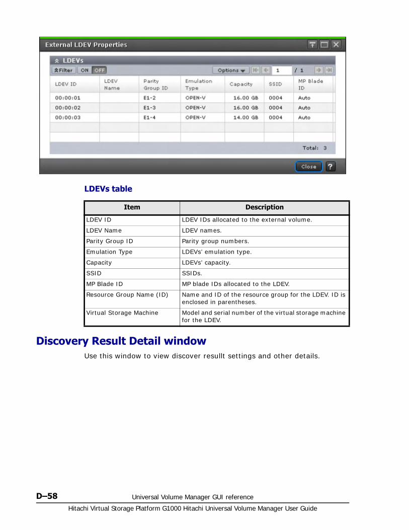
Hitachi Virtual Storage Platform G1000 Hitachi Universal Volume Manager User Guide
D–58 Universal Volume Manager GUI reference
LDEVs table
Discovery Result Detail windowUse this window to view discover resullt settings and other details.
Item Description
LDEV ID LDEV IDs allocated to the external volume.
LDEV Name LDEV names.
Parity Group ID Parity group numbers.
Emulation Type LDEVs’ emulation type.
Capacity LDEVs’ capacity.
SSID SSIDs.
MP Blade ID MP blade IDs allocated to the LDEV.
Resource Group Name (ID) Name and ID of the resource group for the LDEV. ID is enclosed in parentheses.
Virtual Storage Machine Model and serial number of the virtual storage machine for the LDEV.
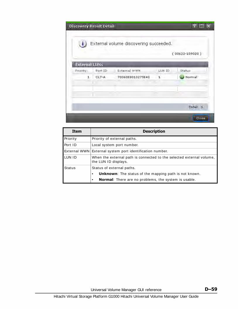
Universal Volume Manager GUI reference D–59Hitachi Virtual Storage Platform G1000 Hitachi Universal Volume Manager User Guide
Item Description
Priority Priority of external paths.
Port ID Local system port number.
External WWN External system port identification number.
LUN ID When the external path is connected to the selected external volume, the LUN ID displays.
Status Status of external paths.
• Unknown: The status of the mapping path is not known.
• Normal: There are no problems, the system is usable.

Hitachi Virtual Storage Platform G1000 Hitachi Universal Volume Manager User Guide
D–60 Universal Volume Manager GUI reference

CA KD E F G H I J L M N O P Q R S T U V W X Y# B ZA B C D E F H I L M N O P R S T U V W
Glossary–1Hitachi Virtual Storage Platform G1000 Hitachi Universal Volume Manager User Guide
Glossary
This glossary defines the special terms used in this document. Click the letter links below to navigate.
A
access attribute
The setting on a logical volume (mainframe or open-systems) that determines whether hosts can read and/or write to the volume.
alternate path
A secondary path (port, target ID, LUN) to a logical volume, in addition to the primary path, that is used as a backup in case the primary path fails.
ALUA
Asymmetric logical unit access
AMS
Hitachi Adaptable Modular Storage
APLB
active path load balancing
array
Another name for a storage system.
B
bind mode
In bind mode the Cache Residency Manager extents are used to hold read and write data for specific extents on volumes. Data written to the

CA KD E F G H I J L M N O P Q R S T U V W X Y# B ZA B C D E F H I L M N O P R S T U V W
Hitachi Virtual Storage Platform G1000 Hitachi Universal Volume Manager User Guide
Glossary–2
Cache Residency Manager bind area is not destaged to the drives. For bind mode, all targeted read and write data is transferred at host data transfer speed.
blade
A computer module, generally a single circuit board, used mostly in servers.
C
cache logical partition (CLPR)
Consists of virtual cache memory that is set up to be allocated to different hosts in contention for cache memory.
capacity
The amount of data storage space available on a physical storage device.
CCI
Command Control Interface
CHA
channel adapter. Another name for a front-end director (FED).
channel path
The communication path between a channel and a control unit. A channel path consists of the physical channel path and the logical path.
CLI
command line interface
CLPR
cache logical partition
command device
A dedicated logical volume used only by Command Control Interface to interface with the storage system. Can be shared by several hosts.
custom volume (CV)
A customized (variable-sized) volume. The size is defined when Virtual LVI/Virtual LUN is used.
CVS
custom volume size

CA KD E F G H I J L M N O P Q R S T U V W X Y# B ZA B C D E F H I L M N O P R S T U V W
Glossary–3Hitachi Virtual Storage Platform G1000 Hitachi Universal Volume Manager User Guide
D
device
A physical or logical unit with a specific function.
device emulation
Indicates the type of logical volume.Mainframe device emulation types provide logical volumes of fixed size, called logical volume images (LVIs), which contain EBCDIC data in CKD format. Typical mainframe device emulation types include 3390-9 and 3390-M. Open-systems device emulation types provide logical volumes of variable size, called logical units (LUs), that contain ASCII data in FBA format. The typical open-systems device emulation type is OPEN-V.
DP
Hitachi Dynamic Provisioning
DP-VOL
Dynamic Provisioning-virtual volume. A virtual volume with no memory space used by Dynamic Provisioning.
dynamic provisioning
An approach to managing storage. Instead of "reserving" a fixed amount of storage, it removes capacity from the available pool when data is actually written to disk. Dynamic provisioning is also referred to as thin provisioning.
E
emulation
The operation of the Hitachi RAID storage system to emulate the characteristics of a different storage system. For device emulation the mainframe host "sees" the logical devices on the RAID storage system as 3390-x devices. For controller emulation the mainframe host "sees" the control units (CUs) on the RAID storage system as 2105 or 2107 controllers.
EXG
external volume group
external port
A fibre-channel port that is configured to be connected to an external storage system for Universal Volume Manager operations.

CA KD E F G H I J L M N O P Q R S T U V W X Y# B ZA B C D E F H I L M N O P R S T U V W
Hitachi Virtual Storage Platform G1000 Hitachi Universal Volume Manager User Guide
Glossary–4
external volume
A logical volume with data that resides on drives which are physically located outside the Hitachi RAID storage system.
F
failover
The process of switching operations from the primary path or host to a secondary path or host when the primary path or host fails.
FCIP
fibre-channel internet protocol
H
HDS
Hitachi Data Systems
host group
A group of hosts of the same operating system platform.
host mode
Operational modes that provide enhanced compatibility with supported host platforms. Used with fibre-channel ports on RAID storage systems.
host mode option
Additional options for fibre-channel ports on RAID storage systems. Provide enhanced functionality for host software and middleware.
I
initial copy
A copy operation that copies all data on the primary volume of a copy pair to the secondary volume of the pair. An initial copy operation is performed when a copy pair is created.
internal volume
A logical volume with data that resides on drives which are physically located within the storage system.
L
LDEV
logical device

CA KD E F G H I J L M N O P Q R S T U V W X Y# B ZA B C D E F H I L M N O P R S T U V W
Glossary–5Hitachi Virtual Storage Platform G1000 Hitachi Universal Volume Manager User Guide
logical device (LDEV)
An individual logical data volume (on multiple drives in a RAID configuration) in the storage system. An LDEV may or may not contain any data and may or may not be defined to any hosts. Each LDEV has a unique identifier or "address" within the storage system composed of the logical disk controller (LDKC) number, control unit (CU) number, and LDEV number. The LDEV IDs within a storage system do not change.
An LDEV formatted for use by open-systems hosts is called a logical unit (LU).
logical partition (LPAR)
A subset of a system's hardware resources that is virtualized as a separate system. For a storage system, logical partitioning can be applied to cache memory or storage capacity.
logical unit (LU)
A logical volume that is configured for use by open-systems hosts (for example, OPEN-V).
logical unit (LU) path
The path between an open-systems host and a logical unit.
logical volume
A logical device (LDEV), or a set of concatenated LDEVs in the case of LUSE, that has been defined to one or more hosts as a single data storage unit. A mainframe volume is called a logical volume image (LVI), and an open-systems volume is called a logical unit. (LU).
LU
logical unit
LUN
logical unit number
LUNM
Hitachi LUN Manager
LV
logical volume
LVM
Logical Volume Manager; logical volume management.

CA KD E F G H I J L M N O P Q R S T U V W X Y# B ZA B C D E F H I L M N O P R S T U V W
Hitachi Virtual Storage Platform G1000 Hitachi Universal Volume Manager User Guide
Glossary–6
M
multi-pathing
A performance and fault-tolerant technique that uses more than one physical connection between the storage system and host system. Also called multipath I/O.
N
NSC
Hitachi TagmaStore® Network Storage Controller
O
OEM
original equipment manufacturer
P
pair
Two logical volumes in a replication relationship in which one volume contains original data to be copied and the other volume contains the copy of the original data. The copy operations can be synchronous or asynchronous, and the pair volumes can be located in the same storage system (in-system replication) or in different storage systems (remote replication).
pair status
Indicates the condition of a copy pair. A pair must have a specific status for specific operations. When an operation completes, the status of the pair changes to the new status.
path mode
Mode that indicates how a path is used between local and external storage systems. The path modes are multi, single, and ALUA.
physical device
A data drive.
pool
A set of volumes that is reserved for storing Thin Image data or Dynamic Provisioning write data.

CA KD E F G H I J L M N O P Q R S T U V W X Y# B ZA B C D E F H I L M N O P R S T U V W
Glossary–7Hitachi Virtual Storage Platform G1000 Hitachi Universal Volume Manager User Guide
pool volume (pool-VOL)
A logical volume that is reserved for storing snapshot data for Thin Image operations or write data for Dynamic Provisioning.
port attribute
Indicates the type of fibre-channel port: target, RCU target, or initiator.
primary volume (P-VOL)
The volume in a copy pair that contains the original data to be replicated. The data in the primary volume is duplicated synchronously or asynchronously on the secondary volume.
The following Hitachi products use the term P-VOL: ShadowImage, ShadowImage for Mainframe, TrueCopy, Universal Replicator, Universal Replicator for Mainframe, and High Availability Manager.
P-VOL
primary volume
R
VSP G1000
Hitachi Virtual Storage Platform G1000
RAID
redundant array of inexpensive disks
RAID group
A redundant array of inexpensive drives (RAID) that have the same capacity and are treated as one group for data storage and recovery. A RAID group contains both user data and parity information, which allows the user data to be accessed in the event that one or more of the drives within the RAID group are not available. The RAID level of a RAID group determines the number of data drives and parity drives and how the data is "striped" across the drives. For RAID1, user data is duplicated within the RAID group, so there is no parity data for RAID1 RAID groups.
A RAID group can also be called an array group or a parity group.
RAID level
The type of RAID implementation. RAID levels include RAID0, RAID1, RAID2, RAID3, RAID4, RAID5 and RAID6.
remote control unit (RCU)
A storage system at a secondary or remote site that is configured to receive remote I/Os from one or more storage systems at the primary or main site.

CA KD E F G H I J L M N O P Q R S T U V W X Y# B ZA B C D E F H I L M N O P R S T U V W
Hitachi Virtual Storage Platform G1000 Hitachi Universal Volume Manager User Guide
Glossary–8
remote copy
Another name for remote replication.
remote replication
Data replication configuration in which the storage system that contains the original data is at a local site and the storage system that contains the copy of the original data is at a remote site. TrueCopy and Universal Replicator provide remote replication.
S
SATA
serial Advanced Technology Attachment
secondary volume
The volume in a copy pair that is the copy of the original data on the primary volume (P-VOL). The following Hitachi products use the term "secondary volume": ShadowImage, TrueCopy, Universal Replicator.
service information message (SIM)
SIMs are generated by a RAID storage system when it detects an error or service requirement. SIMs are reported to hosts and displayed on Storage Navigator.
snapshot
A point-in-time copy of a data volume in a storage system.
SNMP
simple network management protocol
SOM
system option mode (SOM)
SSD
solid-state drive. Another name for a flash drive.
SSID
storage subsystem ID. SSIDs are used for reporting information from the CU to the mainframe operating system. Each group of 64 or 256 volumes requires one SSID, so there are one or four SSIDs per CU image. The user-specified SSIDs are assigned during storage system installation and must be unique to all connected host operating environments.

CA KD E F G H I J L M N O P Q R S T U V W X Y# B ZA B C D E F H I L M N O P R S T U V W
Glossary–9Hitachi Virtual Storage Platform G1000 Hitachi Universal Volume Manager User Guide
S-VOL
secondary volume
system option mode (SOM)
Additional operational parameters for the Unified Storage VM storage systems that enable the storage system to be tailored to unique customer operating requirements. SOMs are set on the service processor.
T
TagmaStore USP
Hitachi TagmaStore® Universal Storage Platform
target port
A fibre-channel port that is configured to receive and process host I/Os.
TC
Hitachi TrueCopy®
U
UR
Hitachi Universal Replicator
URz
Hitachi Universal Replicator for Mainframe
USP VM
Hitachi Universal Storage Platform VM
USP V/VM
Hitachi Universal Storage Platform V/VM
UVM
Hitachi Universal Volume Manager
V
virtual device (VDEV)
A group of logical devices (LDEVs) in a RAID group. A VDEV typically consists of some fixed volumes (FVs) and some free space. The number of fixed volumes is determined by the RAID level and device emulation type.

CA KD E F G H I J L M N O P Q R S T U V W X Y# B ZA B C D E F H I L M N O P R S T U V W
Hitachi Virtual Storage Platform G1000 Hitachi Universal Volume Manager User Guide
Glossary–10
Virtual LUN volume
A custom-size volume with a size defined when Virtual LUN is used. Also called a custom volume (CV).
virtual volume
A storage system volume, also referred to as V-VOL, that has no physical memory space. V-VOLs are used as secondary volumes for Thin Image. VOLs that are used for Dynamic Provisioning, Dynamic Provisioning for Mainframe, Dynamic Tiering, or Dynamic Tiering for Mainframe are also called DP-VOLs.
VLL
Virtual LUN
volume
A logical device (LDEV) that has been defined to one or more hosts as a single data storage unit. A mainframe volume is called a logical volume image (LVI). An open-systems volume is called a logical unit (LU).
V-VOL
virtual volume
W
WMS
Hitachi Workgroup Modular Storage
WWN
worldwide name

Index–1Hitachi Virtual Storage Platform G1000 Hitachi Universal Volume Manager User Guide
Index
AAdd External Volume wizard D–17adding an external path 5–11alternate paths 2–15
CCache Mode info 5–3Cache Mode setting 4–11Cache Residency Manager 3–2capacity 2–9customer support Preface–xiii
Ddeleting volume mapping 5–28destaging data 5–3disconnecting an external path 5–13disconnecting an external volume 5–21disconnecting external volumes 5–20Dynamic Provisioning 3–3
Eedit settings for one ext. volume 5–5editing external volume policies 5–4emulation type
and LDEV capacity listing 2–10external paths
adding 5–11detaching a channel adapter 5–16disconnecting 5–13monitoring 5–2planning 2–14reconnecting 5–14removing and replacing 5–16status, troubleshooting 6–4supported configurations 2–20
External Storagemapping external volumes 4–5
External Storage window D–3external systems
abbreviation in Stor. Nav. 2–18disconnecting 5–20
listing for remote command devices B–2path modes for 2–17planning 2–4powering off, on 5–31supported A–1
external volume groups, planning 2–8external volumes
adjusting capacity 2–13deleting mapping for 5–28disconnecting all 5–20disconnecting one 5–21editing policies 5–4mapping procedure 4–5monitoring 5–2planning for 2–5reconnecting all 5–24reconnecting one 5–26
FFICON channels 2–7
IInflow Control info 5–3Inflow Control setting 4–11interfaces 1–5internal volume, external volume overview 1–2
LLDEVs in mapped volumes 1–3local system
powering off, on 5–31recognizing from external system 4–13
LUN Manager 3–4
Mmainframe volumes, planning for 2–7management LU 2–5mapped volume, preparing to use 4–12mapping a command device B–4MIH 2–7Multi path mode 2–16

Hitachi Virtual Storage Platform G1000 Hitachi Universal Volume Manager User Guide
Index–2
Ppairs, adjusting capacity for 2–13path errors, specific external systems 6–6path mode 2–15path mode, listing per system 2–17path priority, raising and lowering 5–12Performance Monitor 3–4planning
external paths 2–14external volumes 2–5mainframe external volumes 2–7Open system external volumes 2–8volume capacity 2–9workflow 2–2
port attributes, local system settings 4–2port discovery, troubleshooting 6–11ports, setup for external system 4–4priority, raising and lowering 4–8, 5–12Processor Blade setting 4–11processor blade, changing 5–5product version Preface–x
RRAID considerations 2–3reconnecting external path 5–14reconnecting external systems and
volumes 5–24remote command devices B–2restrictions, remote command devices B–3
SSingle path mode 2–15SNMP Agent 3–5software supported 3–1spreadsheets 1–5supported external systems A–1system requirements 2–2
Ttechnical support 6–2Thin Image 3–2Thin Provisioning 3–3Transaction Processing Facility 2–5troubleshooting 6–2TrueCopy 3–4
UUniversal Replicator 3–4Universal Volume Manager
components 1–3how it works 1–2internal, external volumes 1–2planning workflow 2–2requirements 2–2setup 4–2using spreadsheets 1–5volume capacity requirements 2–9
VVirtuall LUN/Virtual LVI 3–5volume discovery, troubleshooting 6–11
WWWN, editing settings 5–9

Hitachi Virtual Storage Platform G1000 Hitachi Universal Volume Manager User Guide

MK-92RD8024-02
Hitachi Data Systems
Corporate Headquarters2845 Lafayette StreetSanta Clara, California 95050-2639U.S.A.www.hds.com
Regional Contact Information
Americas+1 408 970 [email protected]
Europe, Middle East, and Africa+44 (0)1753 [email protected]
Asia Pacific+852 3189 [email protected]