Embed Size (px)
Citation preview
Product Version
Contents
Getting Help
FASTFIND LINKS
Hitachi Virtual Storage Platform G1000Hardware User Guide
MK-92RD8007-02
Hitachi Virtual Storage Platform G1000 Hardware User Guide
ii
© 2014 Hitachi, Ltd. All rights reserved.
No part of this publication may be reproduced or transmitted in any form or by any means, electronic or mechanical, including photocopying and recording, or stored in a database or retrieval system for any purpose without the express written permission of Hitachi, Ltd.
Hitachi, Ltd., reserves the right to make changes to this document at any time without notice and assumes no responsibility for its use. This document contains the most current information available at the time of publication. When new or revised information becomes available, this entire document will be updated and distributed to all registered users.
Some of the features described in this document might not be currently available. Refer to the most recent product announcement for information about feature and product availability, or contact Hitachi Data Systems Corporation at https://portal.hds.com.
Notice: Hitachi, Ltd., products and services can be ordered only under the terms and conditions of the applicable Hitachi Data Systems Corporation agreements. The use of Hitachi, Ltd., products is governed by the terms of your agreements with Hitachi Data Systems Corporation.
Notice on Export Controls: The technical data and technology inherent in this Document may be subject to U.S. export control laws, including the U.S. Export Administration Act and its associated regulations, and may be subject to export or import regulations in other countries. Reader agrees to comply strictly with all such regulations and acknowledges that Reader has the responsibility to obtain licenses to export, re-export, or import the Document and any Compliant Products.
Hitachi is a registered trademark of Hitachi, Ltd., in the United States and other countries. Hitachi Data Systems is a registered trademark and service mark of Hitachi, Ltd., in the United States and other countries.
Archivas, Essential NAS Platform, Hi-Track, ShadowImage, Tagmaserve, Tagmasoft, Tagmasolve, Tagmastore, TrueCopy, Universal Star Network, and Universal Storage Platform are registered trademarks of Hitachi Data Systems Corporation.
AIX, AS/400, DB2, Domino, DS6000, DS8000, Enterprise Storage Server,ESCON, FICON, FlashCopy, IBM, Lotus, MVS, OS/390, RS/6000, S/390,System z9, System z10, Tivoli, VM/ESA, z/OS, z9, z10, zSeries, z/VM, and z/VSE are registered trademarks or trademarks of International Business Machines Corporation.
All other trademarks, service marks, and company names in this document or website are properties of their respective owners.
Microsoft product screen shots are reprinted with permission from Microsoft Corporation.
Contents iiiHitachi Virtual Storage Platform G1000 Hardware User Guide
Contents
Preface . . . . . . . . . . . . . . . . . . . . . . . . . . . . . . . . . . . . . . . . . . . .ixSafety and environmental information . . . . . . . . . . . . . . . . . . . . . . . . . . . . . . . . xIntended audience. . . . . . . . . . . . . . . . . . . . . . . . . . . . . . . . . . . . . . . . . . . . . . xProduct version . . . . . . . . . . . . . . . . . . . . . . . . . . . . . . . . . . . . . . . . . . . . . . . . xRelease notes . . . . . . . . . . . . . . . . . . . . . . . . . . . . . . . . . . . . . . . . . . . . . . . . . xDocument revision level . . . . . . . . . . . . . . . . . . . . . . . . . . . . . . . . . . . . . . . . . . xChanges in this revision . . . . . . . . . . . . . . . . . . . . . . . . . . . . . . . . . . . . . . . . . . xReferenced documents. . . . . . . . . . . . . . . . . . . . . . . . . . . . . . . . . . . . . . . . . . xiDocument conventions. . . . . . . . . . . . . . . . . . . . . . . . . . . . . . . . . . . . . . . . . . xiConvention for storage capacity values . . . . . . . . . . . . . . . . . . . . . . . . . . . . . . xiiAccessing product documentation . . . . . . . . . . . . . . . . . . . . . . . . . . . . . . . . . . xiiGetting help . . . . . . . . . . . . . . . . . . . . . . . . . . . . . . . . . . . . . . . . . . . . . . . . .xiiiComments . . . . . . . . . . . . . . . . . . . . . . . . . . . . . . . . . . . . . . . . . . . . . . . . . .xiii
1 Introduction . . . . . . . . . . . . . . . . . . . . . . . . . . . . . . . . . . . . . . . 1-1System overview . . . . . . . . . . . . . . . . . . . . . . . . . . . . . . . . . . . . . . . . . . . . . 1-2
New features in this release . . . . . . . . . . . . . . . . . . . . . . . . . . . . . . . . . . 1-2Features . . . . . . . . . . . . . . . . . . . . . . . . . . . . . . . . . . . . . . . . . . . . . . . . 1-2
High performance . . . . . . . . . . . . . . . . . . . . . . . . . . . . . . . . . . . . . . . 1-3Scalability . . . . . . . . . . . . . . . . . . . . . . . . . . . . . . . . . . . . . . . . . . . . . 1-3Flexible connectivity . . . . . . . . . . . . . . . . . . . . . . . . . . . . . . . . . . . . . . 1-4High reliability . . . . . . . . . . . . . . . . . . . . . . . . . . . . . . . . . . . . . . . . . . 1-5High flexibility . . . . . . . . . . . . . . . . . . . . . . . . . . . . . . . . . . . . . . . . . . 1-5Nondisruptive service and upgrades. . . . . . . . . . . . . . . . . . . . . . . . . . . 1-6High temperature mode . . . . . . . . . . . . . . . . . . . . . . . . . . . . . . . . . . . 1-6Economical and quiet . . . . . . . . . . . . . . . . . . . . . . . . . . . . . . . . . . . . . 1-7
Hardware overview . . . . . . . . . . . . . . . . . . . . . . . . . . . . . . . . . . . . . . . . . . . 1-8Controller chassis . . . . . . . . . . . . . . . . . . . . . . . . . . . . . . . . . . . . . . . . 1-10Controller components . . . . . . . . . . . . . . . . . . . . . . . . . . . . . . . . . . . . . 1-11Front-end director . . . . . . . . . . . . . . . . . . . . . . . . . . . . . . . . . . . . . . . . 1-13
Supported connections and protocols. . . . . . . . . . . . . . . . . . . . . . . . . 1-14Flexible front-end director installation . . . . . . . . . . . . . . . . . . . . . . . . 1-16
Hitachi Virtual Storage Platform G1000 Hardware User Guide
iv Contents
Supported speeds and cable lengths . . . . . . . . . . . . . . . . . . . . . . . . . 1-17Drive chassis. . . . . . . . . . . . . . . . . . . . . . . . . . . . . . . . . . . . . . . . . . . . 1-18Cache memory . . . . . . . . . . . . . . . . . . . . . . . . . . . . . . . . . . . . . . . . . . 1-22
Memory operation . . . . . . . . . . . . . . . . . . . . . . . . . . . . . . . . . . . . . . 1-23Data protection . . . . . . . . . . . . . . . . . . . . . . . . . . . . . . . . . . . . . . . . 1-23Cache capacity . . . . . . . . . . . . . . . . . . . . . . . . . . . . . . . . . . . . . . . . 1-23Shared memory. . . . . . . . . . . . . . . . . . . . . . . . . . . . . . . . . . . . . . . . 1-24
Cache flash memory . . . . . . . . . . . . . . . . . . . . . . . . . . . . . . . . . . . . . . 1-25CFM operation. . . . . . . . . . . . . . . . . . . . . . . . . . . . . . . . . . . . . . . . . 1-26Cache flash memory capacity . . . . . . . . . . . . . . . . . . . . . . . . . . . . . . 1-26
2 Hardware architecture . . . . . . . . . . . . . . . . . . . . . . . . . . . . . . . . 2-1System architecture overview . . . . . . . . . . . . . . . . . . . . . . . . . . . . . . . . . . . . 2-2Hardware architecture . . . . . . . . . . . . . . . . . . . . . . . . . . . . . . . . . . . . . . . . . 2-2VSP G1000 RAID implementation . . . . . . . . . . . . . . . . . . . . . . . . . . . . . . . . . 2-3
Array groups and RAID levels . . . . . . . . . . . . . . . . . . . . . . . . . . . . . . . . . 2-3RAID1 . . . . . . . . . . . . . . . . . . . . . . . . . . . . . . . . . . . . . . . . . . . . . . . 2-4RAID5 . . . . . . . . . . . . . . . . . . . . . . . . . . . . . . . . . . . . . . . . . . . . . . . 2-5RAID6 . . . . . . . . . . . . . . . . . . . . . . . . . . . . . . . . . . . . . . . . . . . . . . . 2-8
LDEV striping across array groups . . . . . . . . . . . . . . . . . . . . . . . . . . . . . . 2-8CU images, LVIs, and logical units. . . . . . . . . . . . . . . . . . . . . . . . . . . . . . . . 2-10
CU images . . . . . . . . . . . . . . . . . . . . . . . . . . . . . . . . . . . . . . . . . . . . . 2-10Logical volume images. . . . . . . . . . . . . . . . . . . . . . . . . . . . . . . . . . . . . 2-11Logical units . . . . . . . . . . . . . . . . . . . . . . . . . . . . . . . . . . . . . . . . . . . . 2-11
Mainframe operations . . . . . . . . . . . . . . . . . . . . . . . . . . . . . . . . . . . . . . . . 2-11Mainframe compatibility and functionality . . . . . . . . . . . . . . . . . . . . . . . 2-11Mainframe operating system support. . . . . . . . . . . . . . . . . . . . . . . . . . . 2-12Mainframe configuration . . . . . . . . . . . . . . . . . . . . . . . . . . . . . . . . . . . 2-12
Systems operations . . . . . . . . . . . . . . . . . . . . . . . . . . . . . . . . . . . . . . . . . . 2-12Compatibility and functionality . . . . . . . . . . . . . . . . . . . . . . . . . . . . . . . 2-12Systems host platform support . . . . . . . . . . . . . . . . . . . . . . . . . . . . . . . 2-13System configuration . . . . . . . . . . . . . . . . . . . . . . . . . . . . . . . . . . . . . . 2-13
Host modes and host mode options . . . . . . . . . . . . . . . . . . . . . . . . . . . . . . 2-14Device Manager - Storage Navigator . . . . . . . . . . . . . . . . . . . . . . . . . . . . . . 2-14
3 Safety requirements . . . . . . . . . . . . . . . . . . . . . . . . . . . . . . . . . . 3-1General safety guidelines . . . . . . . . . . . . . . . . . . . . . . . . . . . . . . . . . . . . . . . 3-2Work safety guidelines. . . . . . . . . . . . . . . . . . . . . . . . . . . . . . . . . . . . . . . . . 3-2
Warning about moving parts. . . . . . . . . . . . . . . . . . . . . . . . . . . . . . . . . . 3-3Electrical safety guidelines . . . . . . . . . . . . . . . . . . . . . . . . . . . . . . . . . 3-3
4 Site preparation . . . . . . . . . . . . . . . . . . . . . . . . . . . . . . . . . . . . . 4-1Safety requirements . . . . . . . . . . . . . . . . . . . . . . . . . . . . . . . . . . . . . . . . . . 4-2Responsibilities . . . . . . . . . . . . . . . . . . . . . . . . . . . . . . . . . . . . . . . . . . . . . . 4-2
Contents vHitachi Virtual Storage Platform G1000 Hardware User Guide
User responsibilities . . . . . . . . . . . . . . . . . . . . . . . . . . . . . . . . . . . . . . . . 4-2Hitachi Data Systems responsibilities . . . . . . . . . . . . . . . . . . . . . . . . . . . . 4-2
Site Preparation checklist . . . . . . . . . . . . . . . . . . . . . . . . . . . . . . . . . . . . . . . 4-3General site requirements . . . . . . . . . . . . . . . . . . . . . . . . . . . . . . . . . . . . . . 4-5
Equipment clearances . . . . . . . . . . . . . . . . . . . . . . . . . . . . . . . . . . . . . . 4-5Equipment weight . . . . . . . . . . . . . . . . . . . . . . . . . . . . . . . . . . . . . . . . . 4-6System storage requirements . . . . . . . . . . . . . . . . . . . . . . . . . . . . . . . . . 4-6
Data center requirements. . . . . . . . . . . . . . . . . . . . . . . . . . . . . . . . . . . . . . . 4-7Operational requirements . . . . . . . . . . . . . . . . . . . . . . . . . . . . . . . . . . . . . . . 4-7System specifications and requirements. . . . . . . . . . . . . . . . . . . . . . . . . . . . . 4-8
Mechanical specifications . . . . . . . . . . . . . . . . . . . . . . . . . . . . . . . . . . . . 4-8Electrical specifications. . . . . . . . . . . . . . . . . . . . . . . . . . . . . . . . . . . . . 4-10
Grounding. . . . . . . . . . . . . . . . . . . . . . . . . . . . . . . . . . . . . . . . . . . . 4-10Power connection . . . . . . . . . . . . . . . . . . . . . . . . . . . . . . . . . . . . . . 4-11
Environmental specifications . . . . . . . . . . . . . . . . . . . . . . . . . . . . . . . . . 4-12Component weight, heat, airflow, and power consumption . . . . . . . . . . . 4-13Airflow . . . . . . . . . . . . . . . . . . . . . . . . . . . . . . . . . . . . . . . . . . . . . . . . 4-16Equipment noise . . . . . . . . . . . . . . . . . . . . . . . . . . . . . . . . . . . . . . . . . 4-16
Connection diagrams . . . . . . . . . . . . . . . . . . . . . . . . . . . . . . . . . . . . . . . . . 4-17Power Connection diagrams . . . . . . . . . . . . . . . . . . . . . . . . . . . . . . . . . 4-17
UPS power connection . . . . . . . . . . . . . . . . . . . . . . . . . . . . . . . . . . . 4-19Data connection diagrams . . . . . . . . . . . . . . . . . . . . . . . . . . . . . . . . . . 4-20Port Configurations . . . . . . . . . . . . . . . . . . . . . . . . . . . . . . . . . . . . . . . 4-24
Service clearance, floor cutout, and floor load rating . . . . . . . . . . . . . . . . . . . 4-25Single rack configuration . . . . . . . . . . . . . . . . . . . . . . . . . . . . . . . . . . . 4-26Two rack, single controller configuration . . . . . . . . . . . . . . . . . . . . . . . . 4-28Two rack, dual controller configuration. . . . . . . . . . . . . . . . . . . . . . . . . . 4-30Three rack, single controller configuration . . . . . . . . . . . . . . . . . . . . . . . 4-32Three rack, dual controller configuration . . . . . . . . . . . . . . . . . . . . . . . . 4-34Four rack configuration - two controllers (center) . . . . . . . . . . . . . . . . . . 4-36Four rack configuration - two controllers (left) . . . . . . . . . . . . . . . . . . . . 4-38Five rack configuration . . . . . . . . . . . . . . . . . . . . . . . . . . . . . . . . . . . . . 4-40Six rack configuration. . . . . . . . . . . . . . . . . . . . . . . . . . . . . . . . . . . . . . 4-42
5 Power On/Off procedures . . . . . . . . . . . . . . . . . . . . . . . . . . . . . . 5-1Safety and environmental information . . . . . . . . . . . . . . . . . . . . . . . . . . . . . . 5-2Power control panel . . . . . . . . . . . . . . . . . . . . . . . . . . . . . . . . . . . . . . . . . . . 5-2System idle mode . . . . . . . . . . . . . . . . . . . . . . . . . . . . . . . . . . . . . . . . . . . . 5-4Normal power On/Off procedures . . . . . . . . . . . . . . . . . . . . . . . . . . . . . . . . . 5-5
Power on procedures . . . . . . . . . . . . . . . . . . . . . . . . . . . . . . . . . . . . . . . 5-5Power off procedures . . . . . . . . . . . . . . . . . . . . . . . . . . . . . . . . . . . . . . . 5-5
Emergency power off/on procedures . . . . . . . . . . . . . . . . . . . . . . . . . . . . . . . 5-6Emergency power off procedure . . . . . . . . . . . . . . . . . . . . . . . . . . . . . . . 5-6Power on procedure after emergency power off . . . . . . . . . . . . . . . . . . . . 5-7
Battery backup operations . . . . . . . . . . . . . . . . . . . . . . . . . . . . . . . . . . . . . . 5-7Cache backup batteries . . . . . . . . . . . . . . . . . . . . . . . . . . . . . . . . . . . . . 5-8
Hitachi Virtual Storage Platform G1000 Hardware User Guide
vi Contents
Battery life . . . . . . . . . . . . . . . . . . . . . . . . . . . . . . . . . . . . . . . . . . . . 5-9Long term array storage. . . . . . . . . . . . . . . . . . . . . . . . . . . . . . . . . . . . . 5-9
6 Troubleshooting . . . . . . . . . . . . . . . . . . . . . . . . . . . . . . . . . . . . . 6-1Getting help . . . . . . . . . . . . . . . . . . . . . . . . . . . . . . . . . . . . . . . . . . . . . . . . 6-2Solving problems. . . . . . . . . . . . . . . . . . . . . . . . . . . . . . . . . . . . . . . . . . . . . 6-2Service information messages . . . . . . . . . . . . . . . . . . . . . . . . . . . . . . . . . . . 6-2
A Specifications . . . . . . . . . . . . . . . . . . . . . . . . . . . . . . . . . . . . . . A-1System specifications. . . . . . . . . . . . . . . . . . . . . . . . . . . . . . . . . . . . . . . . . . A-2Mechanical specifications . . . . . . . . . . . . . . . . . . . . . . . . . . . . . . . . . . . . . . . A-5Electrical specifications . . . . . . . . . . . . . . . . . . . . . . . . . . . . . . . . . . . . . . . . A-6Environmental specifications. . . . . . . . . . . . . . . . . . . . . . . . . . . . . . . . . . . . . A-8PDU specifications . . . . . . . . . . . . . . . . . . . . . . . . . . . . . . . . . . . . . . . . . . . . A-9
B Comparing VSP G1000 and VSP . . . . . . . . . . . . . . . . . . . . . . . . . B-1Comparison of VSP and VSP G1000. . . . . . . . . . . . . . . . . . . . . . . . . . . . . . . . B-2
C Rack information . . . . . . . . . . . . . . . . . . . . . . . . . . . . . . . . . . . . C-1About the Hitachi Universal rack . . . . . . . . . . . . . . . . . . . . . . . . . . . . . . . . . . C-2
Power considerations . . . . . . . . . . . . . . . . . . . . . . . . . . . . . . . . . . . . . . . C-6PDU specifications . . . . . . . . . . . . . . . . . . . . . . . . . . . . . . . . . . . . . . . . . C-7
Types of PDU plugs . . . . . . . . . . . . . . . . . . . . . . . . . . . . . . . . . . . . . . C-9Power jumper cables . . . . . . . . . . . . . . . . . . . . . . . . . . . . . . . . . . . . C-10
Floor load ratings . . . . . . . . . . . . . . . . . . . . . . . . . . . . . . . . . . . . . . . . C-11Universal Rail Kit . . . . . . . . . . . . . . . . . . . . . . . . . . . . . . . . . . . . . . . . . C-11Installation and maintenance clearance area . . . . . . . . . . . . . . . . . . . . . C-13
Before installing a rack or equipment . . . . . . . . . . . . . . . . . . . . . . . . . . . . . C-14Safety precautions. . . . . . . . . . . . . . . . . . . . . . . . . . . . . . . . . . . . . . . . C-14Electrical and environmental requirements . . . . . . . . . . . . . . . . . . . . . . . C-14
Installation safety . . . . . . . . . . . . . . . . . . . . . . . . . . . . . . . . . . . . . . . . . . . C-15Precautions when using rack-mounted equipment . . . . . . . . . . . . . . . . . C-15
Casters. . . . . . . . . . . . . . . . . . . . . . . . . . . . . . . . . . . . . . . . . . . . . . C-16Rack stability. . . . . . . . . . . . . . . . . . . . . . . . . . . . . . . . . . . . . . . . . . C-16Component weight and location . . . . . . . . . . . . . . . . . . . . . . . . . . . . C-16Height considerations. . . . . . . . . . . . . . . . . . . . . . . . . . . . . . . . . . . . C-17Placing components in the rack. . . . . . . . . . . . . . . . . . . . . . . . . . . . . C-18
Working with racks or components in the rack . . . . . . . . . . . . . . . . . . . . . . . C-18Air vents and airflow . . . . . . . . . . . . . . . . . . . . . . . . . . . . . . . . . . . . . . C-19Blanking panels. . . . . . . . . . . . . . . . . . . . . . . . . . . . . . . . . . . . . . . . . . C-19Cable guidelines . . . . . . . . . . . . . . . . . . . . . . . . . . . . . . . . . . . . . . . . . C-19Power guidelines . . . . . . . . . . . . . . . . . . . . . . . . . . . . . . . . . . . . . . . . . C-19Grounding requirements . . . . . . . . . . . . . . . . . . . . . . . . . . . . . . . . . . . C-20
Contents viiHitachi Virtual Storage Platform G1000 Hardware User Guide
Environmental requirements . . . . . . . . . . . . . . . . . . . . . . . . . . . . . . . . . C-20Preparing for installation . . . . . . . . . . . . . . . . . . . . . . . . . . . . . . . . . . . . . . C-21
Planning considerations . . . . . . . . . . . . . . . . . . . . . . . . . . . . . . . . . . . . C-21Receiving the rack from the shipping carrier . . . . . . . . . . . . . . . . . . . . . . C-22Tools required for installation . . . . . . . . . . . . . . . . . . . . . . . . . . . . . . . . C-22Checking the hardware . . . . . . . . . . . . . . . . . . . . . . . . . . . . . . . . . . . . C-22Casters . . . . . . . . . . . . . . . . . . . . . . . . . . . . . . . . . . . . . . . . . . . . . . . . C-22Leveling feet . . . . . . . . . . . . . . . . . . . . . . . . . . . . . . . . . . . . . . . . . . . . C-23Stabilizing the rack . . . . . . . . . . . . . . . . . . . . . . . . . . . . . . . . . . . . . . . C-24
Installing a Hitachi Universal rack . . . . . . . . . . . . . . . . . . . . . . . . . . . . . . . . C-26Installing side stabilizer plates. . . . . . . . . . . . . . . . . . . . . . . . . . . . . . . . C-26Moving a rack . . . . . . . . . . . . . . . . . . . . . . . . . . . . . . . . . . . . . . . . . . . C-28Securing multiple racks together with a baying kit . . . . . . . . . . . . . . . . . C-28Rear baying instructions . . . . . . . . . . . . . . . . . . . . . . . . . . . . . . . . . . . . C-30Opening and closing the side panels . . . . . . . . . . . . . . . . . . . . . . . . . . . C-32Installing equipment in a rack . . . . . . . . . . . . . . . . . . . . . . . . . . . . . . . . C-32
Installation tasks . . . . . . . . . . . . . . . . . . . . . . . . . . . . . . . . . . . . . . . C-32Installing cage nuts . . . . . . . . . . . . . . . . . . . . . . . . . . . . . . . . . . . . . C-33Installing and uninstalling the anti-tip stabilizer plates . . . . . . . . . . . . . C-33Installing blanking panels . . . . . . . . . . . . . . . . . . . . . . . . . . . . . . . . . C-35
Post-installation considerations . . . . . . . . . . . . . . . . . . . . . . . . . . . . . . . . . . C-35Casters . . . . . . . . . . . . . . . . . . . . . . . . . . . . . . . . . . . . . . . . . . . . . . . . C-35Inspection and cleaning . . . . . . . . . . . . . . . . . . . . . . . . . . . . . . . . . . . . C-35
D System option modes. . . . . . . . . . . . . . . . . . . . . . . . . . . . . . . . . D-1System option modes. . . . . . . . . . . . . . . . . . . . . . . . . . . . . . . . . . . . . . . . . . D-2
E Regulatory Compliance. . . . . . . . . . . . . . . . . . . . . . . . . . . . . . . . E-1Regulatory compliance . . . . . . . . . . . . . . . . . . . . . . . . . . . . . . . . . . . . . . . . . E-2US FCC Notice. . . . . . . . . . . . . . . . . . . . . . . . . . . . . . . . . . . . . . . . . . . . . . . E-4
Electronic emissions testing . . . . . . . . . . . . . . . . . . . . . . . . . . . . . . . . . . E-4European Declaration of Conformity . . . . . . . . . . . . . . . . . . . . . . . . . . . . . . . E-4Notice of export controls . . . . . . . . . . . . . . . . . . . . . . . . . . . . . . . . . . . . . . . E-5
China RoHS? . . . . . . . . . . . . . . . . . . . . . . . . . . . . . . . . . . . . . . . . . . . . . E-5Hazardous and toxic substances . . . . . . . . . . . . . . . . . . . . . . . . . . . . . . . . . . E-5Disposal . . . . . . . . . . . . . . . . . . . . . . . . . . . . . . . . . . . . . . . . . . . . . . . . . . . E-6Recycling . . . . . . . . . . . . . . . . . . . . . . . . . . . . . . . . . . . . . . . . . . . . . . . . . . E-6Electronic emissions certificates . . . . . . . . . . . . . . . . . . . . . . . . . . . . . . . . . . E-6
Glossary
Index

Hitachi Virtual Storage Platform G1000 Hardware User Guide
viii Contents
Preface ixHitachi Virtual Storage Platform G1000 Hardware User Guide
Preface
This manual provides instructions and information to use the Hitachi Virtual Storage Platform G1000 storage system hardware.
Read this document carefully to understand how to use this product, and keep a copy for reference.
This preface includes the following information:
□ Safety and environmental information
□ Intended audience
□ Product version
□ Release notes
□ Document revision level
□ Changes in this revision
□ Referenced documents
□ Document conventions
□ Convention for storage capacity values
□ Accessing product documentation
□ Getting help
□ Comments
Hitachi Virtual Storage Platform G1000 Hardware User Guide
x Preface
Safety and environmental information
Intended audienceThis document is intended for system administrators, Hitachi Data Systems representatives, and authorized service providers who are involved in installing, configuring, and operating the Hitachi Virtual Storage Platform G1000 storage system.
Readers of this document should be familiar with the following:
• Data processing and RAID storage systems and their basic functions.
• The Hitachi Virtual Storage Platform G1000 storage system and the Hitachi Virtual Storage Platform G1000 Product Overview
• The operating system and web browser software on the system hosting the Device Manager - Storage Navigator software.
Product versionThis document revision applies to Hitachi Virtual Storage Platform G1000 microcode 80-02-0x or later.
Release notesThe Hitachi Virtual Storage Platform G1000 Release Notes are available on the Hitachi Data Systems Portal: https://portal.hds.com. Read the release notes before installing and using this product. They may contain requirements or restrictions that are not fully described in this document or updates or corrections to this document.
Document revision level
Changes in this revision• In Introduction on page 1-1 and in Specifications on page A-1, added
information and specifications about new FCoE front-end director and about the new high temperature mode.
• In Specifications on page A-1, added information about increased number of FMDs (up from 182 to 576) and the temperature specifications for the standard and high temperature modes.
Caution: Before operating or working on the Hitachi Virtual Storage Platform G1000 storage system, read the safety and environmental information in Safety requirements on page 3-1, and Regulatory Compliance on page E-1.
Revision Date Description
MK-92RD8007-00 April 2014 Initial release
MK-92RD8007-01 August 2014 Supersedes and replaces MK-92RD8007-00
MK-92RD8007-02 October 2014 Supersedes and replaces MK-92RD8007-01
Preface xiHitachi Virtual Storage Platform G1000 Hardware User Guide
Referenced documentsHitachi Virtual Storage Platform G1000 documentation:
• Hitachi Command Suite User Guide, MK-90HC172
• Hitachi Command Suite Installation and Configuration Guide, MK-90HC173
• Hitachi Virtual Storage Platform G1000 Product Overview, MK-92RD8051
• Hitachi Virtual Storage Platform G1000 Mainframe System Administrator Guide, MK-92RD8016
• Hitachi Virtual Storage Platform G1000 Provisioning Guide for Mainframe Systems, MK-92RD8013
• Hitachi Virtual Storage Platform G1000 Provisioning Guide for Open Systems, MK-92RD8014
• Hitachi Virtual Storage Platform G1000 Performance Guide, MK-92RD8012
• Mainframe Host Attachment and Operations Guide MK-96RD645
• Open-Systems Host Attachment Guide, MK-90RD7037
• Hitachi SNMP Agent User Guide, MK-92RD8015
• Hitachi Volume Shredder User Guide, MK-92RD8025
A complete list of both Hitachi Virtual Storage Platform G1000 block and file documentation is located in the Hitachi Virtual Storage Platform G1000 Product Overview.
Document conventionsThis document uses the following terminology conventions:
Hitachi Data Systems user manuals use the following typographic conventions as needed to clarify information.
Hitachi Data Systems user manuals use the following icons to draw attention to information.
Convention Description
Hitachi Virtual Storage Platform G1000, VSP G1000
Unless otherwise noted, these terms refer to all configurations of the Hitachi Virtual Storage Platform G1000 storage system.
Convention Description
Regular text bold In text: keyboard key, parameter name, property name, hardware label, hardware button, hardware switch
In a procedure: user interface item
Italic Variable, emphasis, reference to document title, called-out term
Screen text Command name and option, drive name, file name, folder name, directory name, code, file content, system and application output, user input
Hitachi Virtual Storage Platform G1000 Hardware User Guide
xii Preface
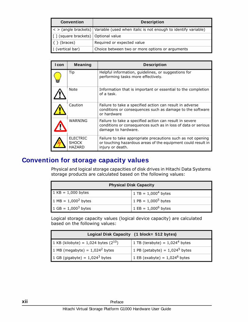
Convention for storage capacity valuesPhysical and logical storage capacities of disk drives in Hitachi Data Systems storage products are calculated based on the following values:
Logical storage capacity values (logical device capacity) are calculated based on the following values:
< > (angle brackets) Variable (used when italic is not enough to identify variable)
[ ] (square brackets) Optional value
{ } (braces) Required or expected value
| (vertical bar) Choice between two or more options or arguments
Icon Meaning Description
Tip Helpful information, guidelines, or suggestions for performing tasks more effectively.
Note Information that is important or essential to the completion of a task.
Caution Failure to take a specified action can result in adverse conditions or consequences such as damage to the software or hardware
WARNING Failure to take a specified action can result in severe conditions or consequences such as in loss of data or serious damage to hardware.
ELECTRIC SHOCK HAZARD
Failure to take appropriate precautions such as not opening or touching hazardous areas of the equipment could result in injury or death.
Convention Description
Physical Disk Capacity
1 KB = 1,000 bytes 1 TB = 1,0004 bytes
1 MB = 1,0002 bytes 1 PB = 1,0005 bytes
1 GB = 1,0003 bytes 1 EB = 1,0006 bytes
Logical Disk Capacity (1 block= 512 bytes)
1 KB (kilobyte) = 1,024 bytes (210) 1 TB (terabyte) = 1,0244 bytes
1 MB (megabyte) = 1,0242 bytes 1 PB (petabyte) = 1,0245 bytes
1 GB (gigabyte) = 1,0243 bytes 1 EB (exabyte) = 1,0246 bytes
Preface xiiiHitachi Virtual Storage Platform G1000 Hardware User Guide
Accessing product documentationThe Hitachi Unified Storage VM user documentation is available on the Hitachi Data Systems Support Portal: https://Portal.HDS.com. Check this site for the most current documentation, including important updates that may have been made after the release of the product.
Getting helpThe Hitachi Data Systems customer support staff is available 24 hours a day, seven days a week. If you need technical support, log on to the Hitachi Data Systems support portal for contact information: https://Portal.HDS.com
CommentsPlease send us your comments on this document: [email protected]. Include the document title, number, and revision. Please refer to specific sections and paragraphs whenever possible.
Thank you!

Hitachi Virtual Storage Platform G1000 Hardware User Guide
xiv Preface

1
Introduction 1–1Hitachi Virtual Storage Platform G1000 Hardware User Guide
Introduction
This chapter briefly describes the hardware components used i n the Hitachi Virtual Storage Platform G1000 storage system.
□ System overview
□ Hardware overview
Hitachi Virtual Storage Platform G1000 Hardware User Guide
1–2 Introduction
System overviewThe Hitachi Virtual Storage Platform G1000 storage system (VSP G1000) is a high-capacity, high performance unified block and file enterprise storage system that offers a wide range of storage and data services, software, logical partitioning, and simplified and unified data replication across heterogeneous storage systems.
New features in this releaseThe following features have been added to the VSP G1000 in the current release:
• 16 port, 10Gbps Fibre Channel over Ethernet (FCoE) front-end director
• High temperature mode - a licensed feature that allows the storage system to be run at either standard temperature (up to 89.6°F / 32°C) or at higher temperatures (up to 104°F / 40°C) saving energy and cooling costs.
• Increased the maximum number of flash module drives from 192 to 576.
FeaturesThe VSP G1000 storage system includes several state-of-the art advances in hardware technology that improve reliability, serviceability and access to drives and other components when maintenance is needed. These include:
• Hitachi Accelerated Flash storage offers a patented data-center-class design and rack-optimized form factor that delivers more than 600 TB per system. It supports a sustained performance of 100,000 8K I/O per second, per device, with low and consistent response time
• The latest 2.5 in. and 3.5 inch 6 Gb/sec SAS drives support lower power consumption and higher density per rack with up to 2,304 drives in six 19 in. standard racks. See Table A-2 Drive Specifications on page A-4.
• Hitachi NAS Platform hardware accelerated network protocols support up to 2 GB/sec throughput for sequential workloads and up to 1.2 million NFS operations per second.
• Efficient caching makes up to 2 TB global cache dynamically accessible by all connected hosts and Hitachi NAS Platform nodes.
• Primary data deduplication using hardware-based SHA-256 calculation engines. They enable up to 90% capacity savings while maintaining high performance.
• Controller racks can be placed up to 100 meters apart, providing maximum flexibility to optimize data center space usage and to provide ease of access for operation and maintenance. Drive racks connected to the controller racks must be placed next to the controller rack.
• High-speed 8-core CPUs in the virtual storage directors, expanded cache memory (up to 2 GB per 6-rack system), flexible installation, and increased drive types and capacities.
• Nondisruptive migration is available as a service from Hitachi Data Systems authorized service representatives.
Introduction 1–3Hitachi Virtual Storage Platform G1000 Hardware User Guide
• High temperature mode is a licensed feature that allows the storage system to be run at either standard temperature (60.8°F to 89.6°F / 16°C to 32°C) or at higher temperatures (60.8°F to 104°F / 16°C to 40°C) in a data center, saving energy and cooling costs. See High temperature mode on page 1-6.
High performance
The VSP G1000 offers the highest performance of the enterprise-class systems offered by Hitachi, up to three times the performance of the Virtual Storage Platform. It offers high performance that enables consolidation and real-time applications, a wide range of storage and data services, software, logical partitioning, along with simplified and unified data replication across heterogeneous storage systems. Its large-scale, enterprise class virtualization layer, combined with Hitachi Dynamic Tiering and thin provisioning software, allows you to consolidate internal and external storage into one pool.
The VSP G1000 includes several features that improve system performance:
• Integrated data and storage management using Hitachi Command Suite and Device Manager - Storage Navigator. These provide integrated management across all Hitachi storage systems and data types.
• Disk drives with 7,200, 10,000, or 15,000 RPM
• SSD drives with ultra-high-speed response
• High-speed data transfer between the back-end directors and the drives at a rate of 6 GB/sec with the SAS interface
• Scalable and upgradable system performance, described in the following section.
For information about the differences between VSP and VSP G1000, see Comparing VSP G1000 and VSP on page B-1.
Scalability
The VSP G1000 storage system offers an entirely new type of scalable and adaptable integrated active-active architecture that supports integrated management. It offers greater performance, reliability, and flexibility than other Hitachi Data Systems storage systems. It can be configured in several ways as needed to meet performance and storage requirements.
Scalable system performance
System performance can be optimized according to user needs, and can be easily upgraded (in small or large increments) as storage needs increase. The following table shows the supported configurations.
Hitachi Virtual Storage Platform G1000 Hardware User Guide
1–4 Introduction
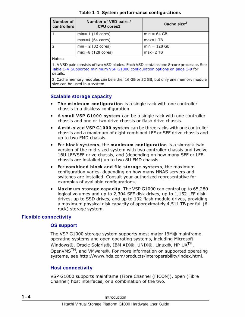
Table 1-1 System performance configurations
Scalable storage capacity• The minimum configuration is a single rack with one controller
chassis in a diskless configuration.
• A small VSP G1000 system can be a single rack with one controller chassis and one or two drive chassis or flash drive chassis.
• A mid-sized VSP G1000 system can be three racks with one controller chassis and a maximum of eight combined LFF or SFF drive chassis and up to two FMD chassis.
• For block systems, the maximum configuration is a six-rack twin version of the mid-sized system with two controller chassis and twelve 16U LFF/SFF drive chassis, and (depending on how many SFF or LFF chassis are installed) up to two 8U FMD chassis.
• For combined block and file storage systems, the maximum configuration varies, depending on how many HNAS servers and switches are installed. Consult your authorized representative for examples of available configurations.
• Maximum storage capacity. The VSP G1000 can control up to 65,280 logical volumes and up to 2,304 SFF disk drives, up to 1,152 LFF disk drives, up to SSD drives, and up to 192 flash module drives, providing a maximum physical disk capacity of approximately 4,511 TB per full (6-rack) storage system.
Flexible connectivity
OS support
The VSP G1000 storage system supports most major IBM® mainframe operating systems and open operating systems, including Microsoft Windows®, Oracle Solaris®, IBM AIX®, UNIX®, Linux®, HP-UXTM, OpenVMSTM, and VMware®. For more information on supported operating systems, see http://www.hds.com/products/interoperability/index.html.
Host connectivity
VSP G1000 supports mainframe (Fibre Channel (FICON)), open (Fibre Channel) host interfaces, or a combination of the two.
Number of controllers
Number of VSD pairs /CPU cores1 Cache size2
1 min= 1 (16 cores)
max=4 (64 cores)
min = 64 GB
max=1 TB
2 min= 2 (32 cores)
max=8 (128 cores)
min = 128 GB
max=2 TB
Notes:
1. A VSD pair consists of two VSD blades. Each VSD contains one 8-core processor. See Table 1-4 Supported minimum VSP G1000 configuration options on page 1-9 for details.
2. Cache memory modules can be either 16 GB or 32 GB, but only one memory module size can be used in a system.
Introduction 1–5Hitachi Virtual Storage Platform G1000 Hardware User Guide
High reliability
The VSP G1000 storage system includes the following features that enhance reliability:
• Multiple RAID configurations. The system supports RAID6 (6D+2P and 14D+2P), RAID5 (3D+1P and 7D+1P), and RAID1 (2D+2D and 4D+4D).
• Duplicate hardware. The main modules in the controller chassis and drive chassis are configured in redundant pairs so that if any module fails, the duplicate module takes over until the failed component is replaced. These include power supplies, VSD pairs, cache path controllers, front-end directors, back-end directors, and drives. During that time, the storage system continues normal operation with zero data loss.
• Protection from power failures. In the event of a partial power loss (one phase) the system operates normally on the other phase until power is restored. In the event of a full power loss, the cache backup modules keep the cache alive for 32 minutes while the system copies the system configuration information and all data in the cache to a cache flash drive (SSD).
High flexibility
The VSP G1000 storage system is available in many configurations, from a small, one rack, diskless system, to a large, six-rack system that includes two controller chassis, up to 2,304 SFF drives, up to 1,152 LFF drives, up to 384 SSD drives, up to 192 flash module drives, and a total of 2 TB cache, according to your storage needs. It can be easily reconfigured as storage needs change.
The system supports both block-only and unified (block and file) configurations in open and mainframe environments. The unified systems contain Hitachi Network Attached Storage servers and switches in addition to the block controller and storage drives.
The VSP G1000 storage system provides the foundation for matching application requirements to different classes of storage and delivering critical services, including:
• Business continuity services
• Content management services (search, indexing)
• Thin provisioning
• Dynamic Tiering
• High availability
• Security services
• I/O load balancing
• Data classification
• File management services
Hitachi Virtual Storage Platform G1000 Hardware User Guide
1–6 Introduction
Nondisruptive service and upgrades
The VSP G1000 storage system is designed so that service and upgrades can be performed without interrupting normal operations.
• Main components can be “hot swapped” (added, removed, or replaced without disruption) during normal operation. These include every module in the controller chassis and the drive chassis, such as power supplies, virtual storage directors, front-end directors, and back-end directors, cache and cache backup modules, SVPs, and drives.
• A service processor (SVP) mounted in the controller chassis monitors the running condition of the storage system. Connecting the SVP with a service center allows authorized service personnel to maintain the system remotely.
• Online non-disruptive upgrade of the storage system microcode (firmware) can be performed without shutting down or rebooting the storage system during normal operation. The firmware is stored in shared memory (part of the cache memory module) and transferred in a batch, reducing the number of transfers from the SVP to the controller chassis over the LAN. Replacing the firmware online is fast because the storage system uses two or more processors at the same time.
• Nondisruptive data migration is available as a service from Hitachi Data Systems authorized service representatives. Self-service nondisruptive data migration is planned for a future release.
High temperature mode
High temperature mode is a licensed feature that allows the storage system to be run at either standard temperature (60.8°F to 89.6°F / 16°C to 32°C) or at higher temperatures (60.8°F to 104°F / 16°C to 40°C) in a data center, saving energy and cooling costs. Temperature sensors at the air inlets in the in the primary microprocessor blades measure the ambient air temperature.
High temperature mode is set via the Edit High Temperature Mode window in the Storage Navigator GUI. When high temperature mode is disabled, a temperature alert (SIM) displays when the temperature in the storage system exceeds 89.6°F / 32°C. When high temperature mode is enabled, the temperature alert (SIM) displays when the temperature in the storage system exceeds 104°F / 40°C.
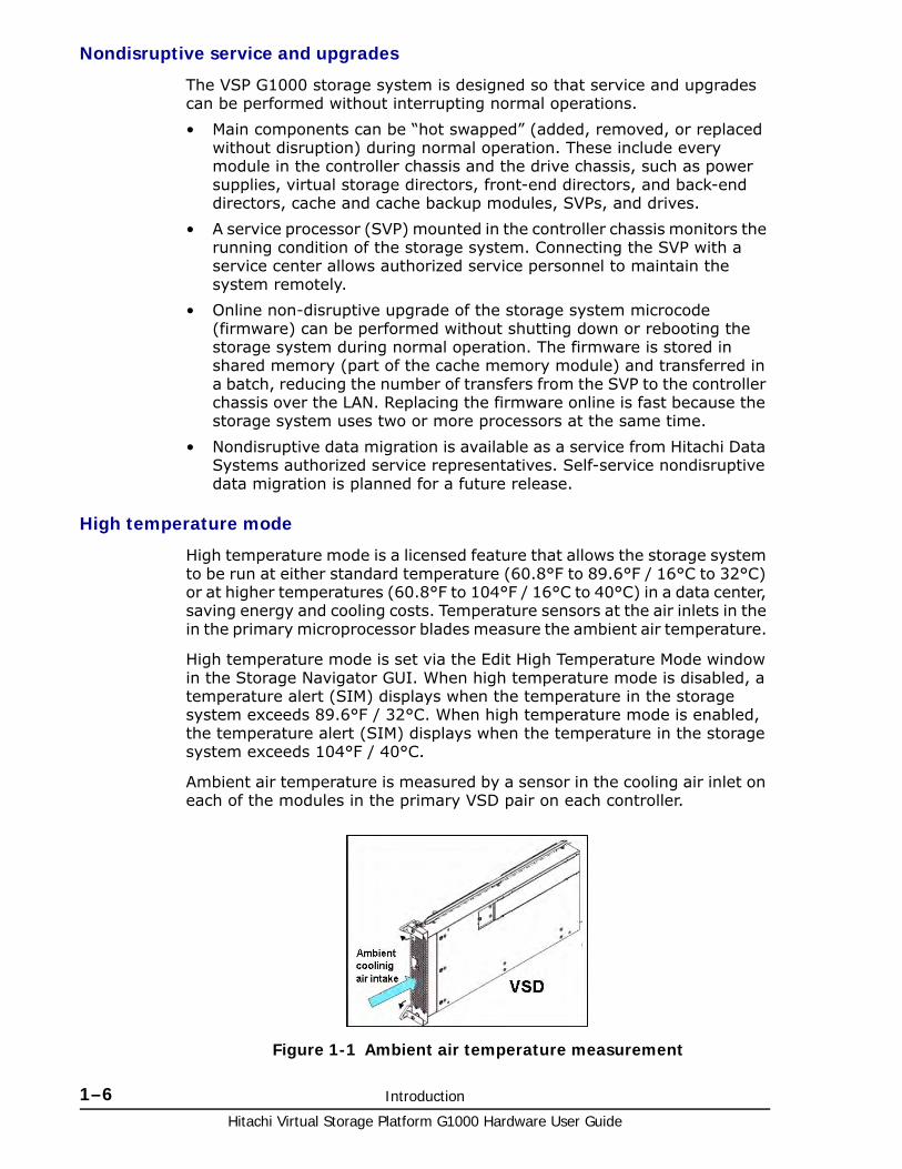
Ambient air temperature is measured by a sensor in the cooling air inlet on each of the modules in the primary VSD pair on each controller.
Figure 1-1 Ambient air temperature measurement

Introduction 1–7Hitachi Virtual Storage Platform G1000 Hardware User Guide
Economical and quiet
The speed of the fans in the controller and drive chassis are controlled by sensors in the units that measure the temperature of the exhaust air and set the fans to the speed necessary to maintain the unit temperature within a preset range. When the system is not busy, it generates less heat and fan speed is reduced, saving energy and reducing the noise level. When the system is in idle mode, the HDD drives spin down and the VSDs are in sleep mode. The system uses 40% to 60% (depending on the number of drives) of the normal power and generates only 40% to 60% of the heat generated in normal operation.
Caution: Important information about using high temperature mode. See the Hitachi Virtual Storage Platform G1000 Mainframe System Administrator Guide for additional information.
• Notify Technical Support. Before enabling high temperature mode, call the Hitachi Data Systems Support Center. They may have updates or additional information besides the following notes.
• Operating with flash module drives. Do not enable high temperature mode if the system contains FMDs. FMDs can only be used in the standard temperature environment.
• Operating altitude. Because thinner air will not provide sufficient cooling, do not enable high temperature mode if the system is located above 4920 ft / 1,500 m. A storage system can be operated up to 9842 ft / 3,000 m above sea level in standard temperature mode.
• Cache Flash Memory battery life. When high temperature mode is enabled, the cache flash memory battery life will be reduced to two-thirds of the battery life that remains at the time when high temperature mode is enabled.
Example 1: A new cache flash memory battery has three years of usable life when operated in a standard temperature environment. If you enable high temperature mode when the battery is new, the battery life will be reduced to two years.
Example 2: The storage system is used for two years at normal temperature mode. The cache battery has one year of usable life remaining at that time. If you enable high temperature mode, the life of the battery will be reduced to eight months.
• Cache Flash Memory battery date. When high temperature mode is enabled, the battery replacement notice displays one year earlier than when high temperature mode is disabled.
After high temperature mode is enabled, the date of the battery replacement notice cannot be changed back to normal, even if high temperature mode is disabled. When high temperature mode is enabled, a confirmation message is displayed.
• System noise. When the storage system is used in a high temperature environment near 104°F / 40°C, the fans operate at high speed, increasing system noise. See Table A-10 VSP G1000 system noise levels on page A-9 for detailed information.
Hitachi Virtual Storage Platform G1000 Hardware User Guide
1–8 Introduction
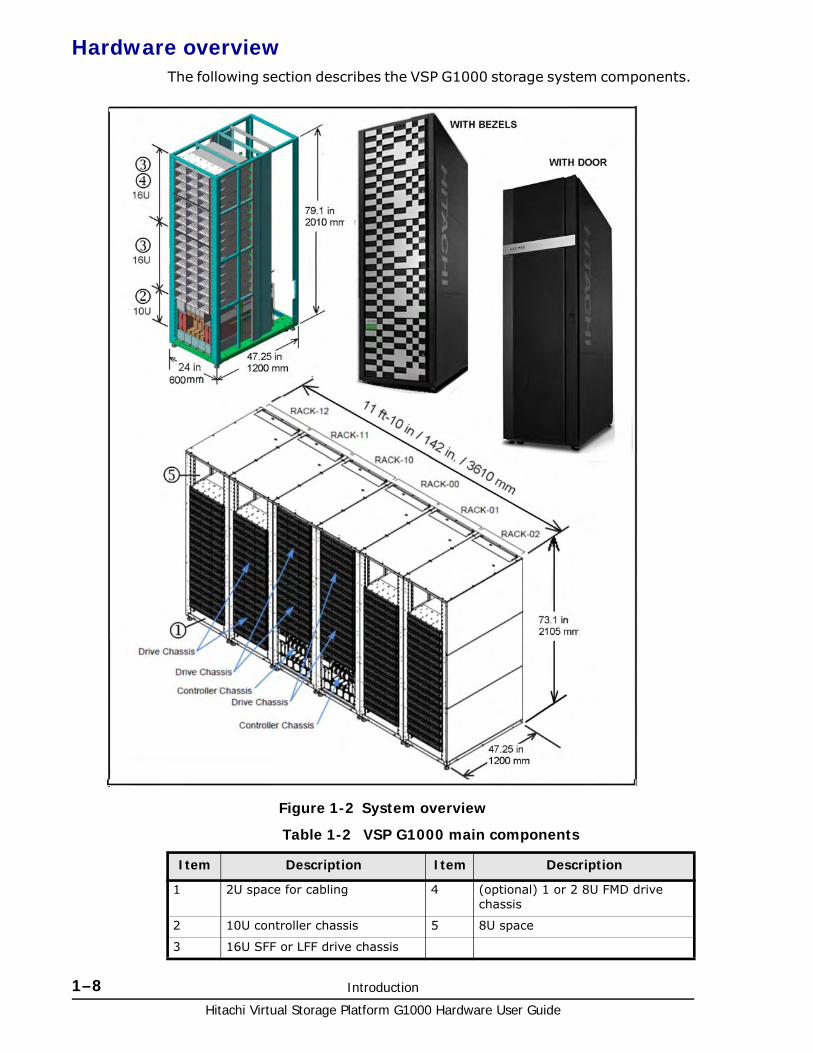
Hardware overviewThe following section describes the VSP G1000 storage system components.
Table 1-2 VSP G1000 main components
Figure 1-2 System overview
Item Description Item Description
1 2U space for cabling 4 (optional) 1 or 2 8U FMD drive chassis
2 10U controller chassis 5 8U space
3 16U SFF or LFF drive chassis
Introduction 1–9Hitachi Virtual Storage Platform G1000 Hardware User Guide
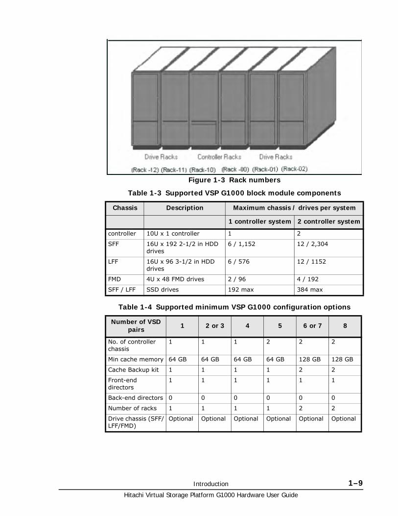
Table 1-3 Supported VSP G1000 block module components
Table 1-4 Supported minimum VSP G1000 configuration options
Figure 1-3 Rack numbers
Chassis Description Maximum chassis / drives per system
1 controller system 2 controller system
controller 10U x 1 controller 1 2
SFF 16U x 192 2-1/2 in HDD drives
6 / 1,152 12 / 2,304
LFF 16U x 96 3-1/2 in HDD drives
6 / 576 12 / 1152
FMD 4U x 48 FMD drives 2 / 96 4 / 192
SFF / LFF SSD drives 192 max 384 max
Number of VSD pairs 1 2 or 3 4 5 6 or 7 8
No. of controller chassis
1 1 1 2 2 2
Min cache memory 64 GB 64 GB 64 GB 64 GB 128 GB 128 GB
Cache Backup kit 1 1 1 1 2 2
Front-end directors
1 1 1 1 1 1
Back-end directors 0 0 0 0 0 0
Number of racks 1 1 1 1 2 2
Drive chassis (SFF/LFF/FMD)
Optional Optional Optional Optional Optional Optional
Hitachi Virtual Storage Platform G1000 Hardware User Guide
1–10 Introduction
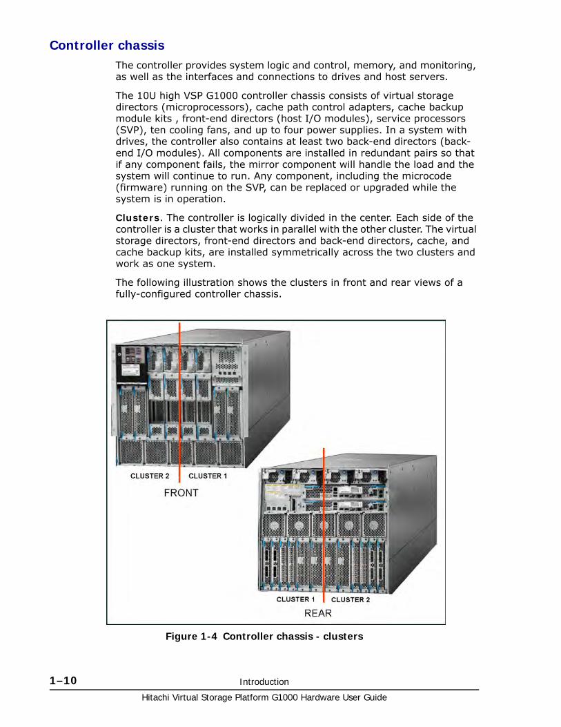
Controller chassisThe controller provides system logic and control, memory, and monitoring, as well as the interfaces and connections to drives and host servers.
The 10U high VSP G1000 controller chassis consists of virtual storage directors (microprocessors), cache path control adapters, cache backup module kits , front-end directors (host I/O modules), service processors (SVP), ten cooling fans, and up to four power supplies. In a system with drives, the controller also contains at least two back-end directors (back-end I/O modules). All components are installed in redundant pairs so that if any component fails, the mirror component will handle the load and the system will continue to run. Any component, including the microcode (firmware) running on the SVP, can be replaced or upgraded while the system is in operation.
Clusters. The controller is logically divided in the center. Each side of the controller is a cluster that works in parallel with the other cluster. The virtual storage directors, front-end directors and back-end directors, cache, and cache backup kits, are installed symmetrically across the two clusters and work as one system.
The following illustration shows the clusters in front and rear views of a fully-configured controller chassis.
Figure 1-4 Controller chassis - clusters
Introduction 1–11Hitachi Virtual Storage Platform G1000 Hardware User Guide
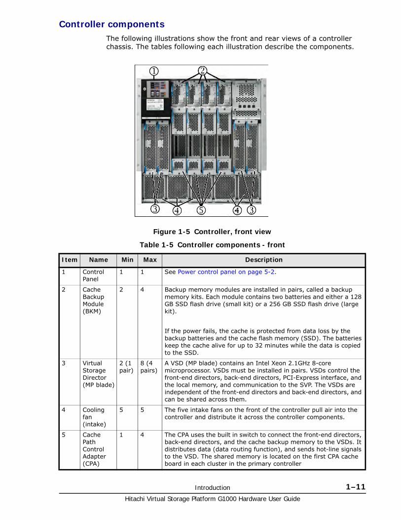
Controller componentsThe following illustrations show the front and rear views of a controller chassis. The tables following each illustration describe the components.
Table 1-5 Controller components - front
Figure 1-5 Controller, front view
Item Name Min Max Description
1 Control Panel
1 1 See Power control panel on page 5-2.
2 Cache Backup Module (BKM)
2 4 Backup memory modules are installed in pairs, called a backup memory kits. Each module contains two batteries and either a 128 GB SSD flash drive (small kit) or a 256 GB SSD flash drive (large kit).
If the power fails, the cache is protected from data loss by the backup batteries and the cache flash memory (SSD). The batteries keep the cache alive for up to 32 minutes while the data is copied to the SSD.
3 Virtual Storage Director (MP blade)
2 (1 pair)
8 (4 pairs)
A VSD (MP blade) contains an Intel Xeon 2.1GHz 8-core microprocessor. VSDs must be installed in pairs. VSDs control the front-end directors, back-end directors, PCI-Express interface, and the local memory, and communication to the SVP. The VSDs are independent of the front-end directors and back-end directors, and can be shared across them.
4 Cooling fan (intake)
5 5 The five intake fans on the front of the controller pull air into the controller and distribute it across the controller components.
5 Cache Path Control Adapter (CPA)
1 4 The CPA uses the built in switch to connect the front-end directors, back-end directors, and the cache backup memory to the VSDs. It distributes data (data routing function), and sends hot-line signals to the VSD. The shared memory is located on the first CPA cache board in each cluster in the primary controller
Hitachi Virtual Storage Platform G1000 Hardware User Guide
1–12 Introduction
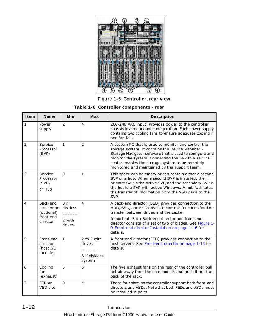
Table 1-6 Controller components - rear
Figure 1-6 Controller, rear view
Item Name Min Max Description
1 Power supply
2 4 200-240 VAC input. Provides power to the controller chassis in a redundant configuration. Each power supply contains two cooling fans to ensure adequate cooling if one fan fails.
2 Service Processor (SVP)
1 2 A custom PC that is used to monitor and control the storage system. It contains the Device Manager - Storage Navigator software that is used to configure and monitor the system. Connecting the SVP to a service center enables the storage system to be remotely monitored and maintained by the support team.
3 Service Processor (SVP)
or Hub
0 1 This space can be empty or can contain either a second SVP or a hub. When a second SVP is installed, the primary SVP is the active SVP, and the secondary SVP is the hot idle SVP with active Windows. A hub facilitates the transfer of information from the VSD pairs to the SVP.
4 Back-end director or (optional) front-end director
0 if diskless
---------
2 with drives
4 A back-end director (BED) provides connection to the HDD, SSD, and FMD drives. It controls functions for data transfer between drives and the cache
Important! Each Back-end director and front-end director consists of a set of two of blades. See Figure 1-9 Front-end director Installation on page 1-16 for details.
5 Front-end director (host I/O module)
1 2 to 5 with drives
----------
6 if diskless system
A front-end director (FED) provides connection to the host servers. See Front-end director on page 1-13 for details.
6 Cooling fan (exhaust)
5 5 The five exhaust fans on the rear of the controller pull hot air away from the components and push it out the back of the rack.
7 FED or VSD slot
0 4 These four slots on the controller support both front-end directors and VSDs. Note that both FEDs and VSDs must be installed in pairs.
Introduction 1–13Hitachi Virtual Storage Platform G1000 Hardware User Guide
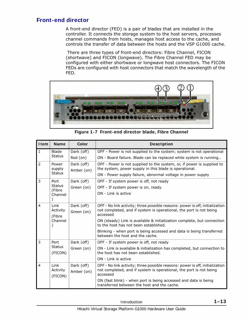
Front-end directorA front-end director (FED) is a pair of blades that are installed in the controller. It connects the storage system to the host servers, processes channel commands from hosts, manages host access to the cache, and controls the transfer of data between the hosts and the VSP G1000 cache.
There are three types of front-end directors: Fibre Channel, FICON (shortwave) and FICON (longwave). The Fibre Channel FED may be configured with either shortwave or longwave host connectors. The FICON FEDs are configured with host connectors that match the wavelength of the FED.
Figure 1-7 Front-end director blade, Fibre Channel
Item Name Color Description
1 Blade Status
Dark (off)
Red (on)
OFF - Power is not supplied to the system; system is not operational
ON - Board failure. Blade can be replaced while system is running..
2 Power supply Status
Dark (off)
Amber (on)
OFF - Power is not supplied to the system, or, if power is supplied to the system, power supply in this blade is operational.
ON - Power supply failure, abnormal voltage in power supply
3 Port Status (Fibre Channel)
Dark (off)
Green (on)
OFF - If system power is off, not ready
OFF - If system power is on, ready.
ON - Link is active
4 Link Activity
(Fibre Channel)
Dark (off)
Green (on)
OFF - No link activity; three possible reasons: power is off, initialization not completed, and if system is operational, the port is not being accessed
ON (steady) Link is available & initialization complete, but connection to the host has not been established.
Blinking - when port is being accessed and data is being transferred between the host and the cache.
3 Port Status
(FICON)
Dark (off)
Green (on)
OFF - If system power is off, not ready
ON - Link is available & initialization has completed, but connection to the host has not been established.
ON - Link is active
4 Link Activity
(FICON)
Dark (off)
Amber (on)
OFF - No link activity; three possible reasons: power is off, initialization not completed, and if system is operational, the port is not being accessed
ON (fast blink) - when port is being accessed and data is being transferred between the host and the cache.
Hitachi Virtual Storage Platform G1000 Hardware User Guide
1–14 Introduction
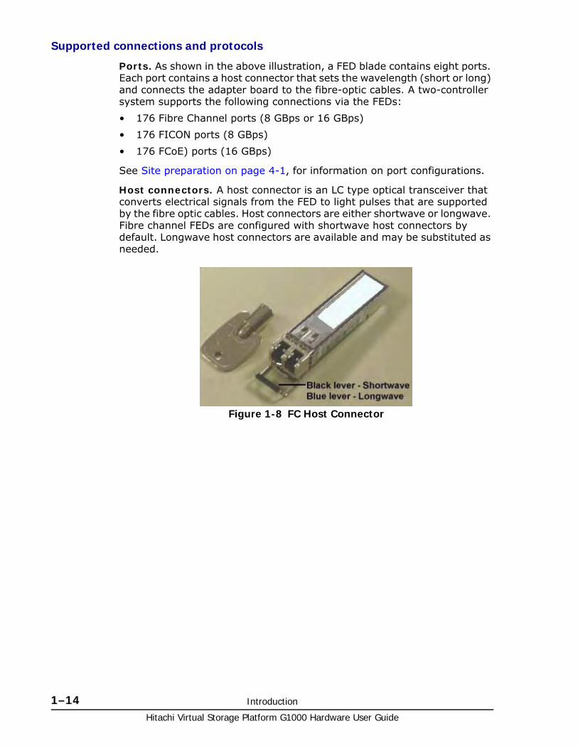
Supported connections and protocols
Ports. As shown in the above illustration, a FED blade contains eight ports. Each port contains a host connector that sets the wavelength (short or long) and connects the adapter board to the fibre-optic cables. A two-controller system supports the following connections via the FEDs:
• 176 Fibre Channel ports (8 GBps or 16 GBps)
• 176 FICON ports (8 GBps)
• 176 FCoE) ports (16 GBps)
See Site preparation on page 4-1, for information on port configurations.
Host connectors. A host connector is an LC type optical transceiver that converts electrical signals from the FED to light pulses that are supported by the fibre optic cables. Host connectors are either shortwave or longwave. Fibre channel FEDs are configured with shortwave host connectors by default. Longwave host connectors are available and may be substituted as needed.
Figure 1-8 FC Host Connector
Introduction 1–15Hitachi Virtual Storage Platform G1000 Hardware User Guide
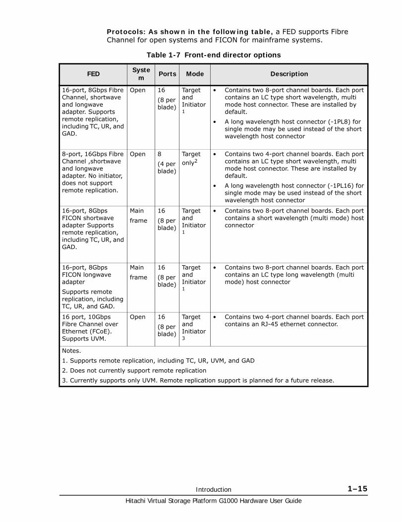
Protocols: As shown in the following table, a FED supports Fibre Channel for open systems and FICON for mainframe systems.
Table 1-7 Front-end director options
FED System Ports Mode Description
16-port, 8Gbps Fibre Channel, shortwave and longwave adapter. Supports remote replication, including TC, UR, and GAD.
Open 16
(8 per blade)
Target and Initiator1
• Contains two 8-port channel boards. Each port contains an LC type short wavelength, multi mode host connector. These are installed by default.
• A long wavelength host connector (-1PL8) for single mode may be used instead of the short wavelength host connector
8-port, 16Gbps Fibre Channel ,shortwave and longwave adapter. No initiator, does not support remote replication.
Open 8
(4 per blade)
Target only2
• Contains two 4-port channel boards. Each port contains an LC type short wavelength, multi mode host connector. These are installed by default.
• A long wavelength host connector (-1PL16) for single mode may be used instead of the short wavelength host connector
16-port, 8Gbps FICON shortwave adapter Supports remote replication, including TC, UR, and GAD.
Main
frame
16
(8 per blade)
Target and Initiator1
• Contains two 8-port channel boards. Each port contains a short wavelength (multi mode) host connector
16-port, 8Gbps FICON longwave adapter
Supports remote replication, including TC, UR, and GAD.
Main
frame
16
(8 per blade)
Target and Initiator1
• Contains two 8-port channel boards. Each port contains an LC type long wavelength (multi mode) host connector
16 port, 10Gbps Fibre Channel over Ethernet (FCoE). Supports UVM.
Open 16
(8 per blade)
Target and Initiator3
• Contains two 4-port channel boards. Each port contains an RJ-45 ethernet connector.
Notes.
1. Supports remote replication, including TC, UR, UVM, and GAD
2. Does not currently support remote replication
3. Currently supports only UVM. Remote replication support is planned for a future release.
Hitachi Virtual Storage Platform G1000 Hardware User Guide
1–16 Introduction
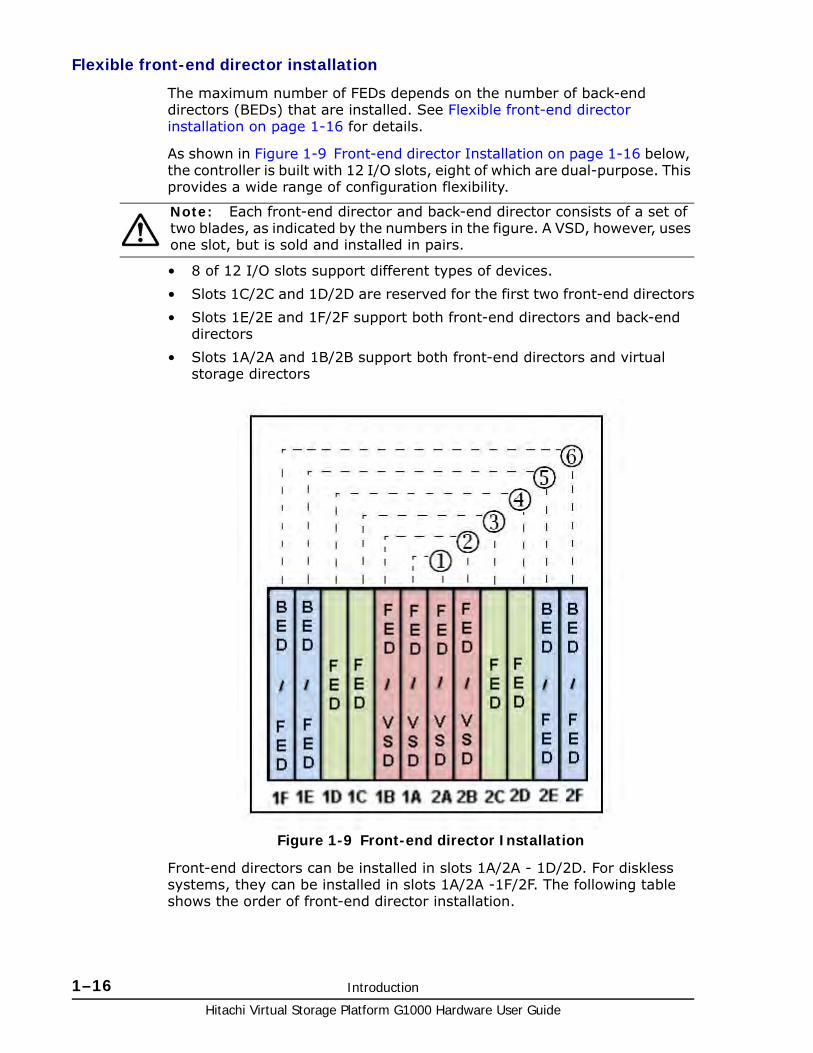
Flexible front-end director installation
The maximum number of FEDs depends on the number of back-end directors (BEDs) that are installed. See Flexible front-end director installation on page 1-16 for details.
As shown in Figure 1-9 Front-end director Installation on page 1-16 below, the controller is built with 12 I/O slots, eight of which are dual-purpose. This provides a wide range of configuration flexibility.
• 8 of 12 I/O slots support different types of devices.
• Slots 1C/2C and 1D/2D are reserved for the first two front-end directors
• Slots 1E/2E and 1F/2F support both front-end directors and back-end directors
• Slots 1A/2A and 1B/2B support both front-end directors and virtual storage directors
Front-end directors can be installed in slots 1A/2A - 1D/2D. For diskless systems, they can be installed in slots 1A/2A -1F/2F. The following table shows the order of front-end director installation.
Note: Each front-end director and back-end director consists of a set of two blades, as indicated by the numbers in the figure. A VSD, however, uses one slot, but is sold and installed in pairs.
Figure 1-9 Front-end director Installation
Introduction 1–17Hitachi Virtual Storage Platform G1000 Hardware User Guide
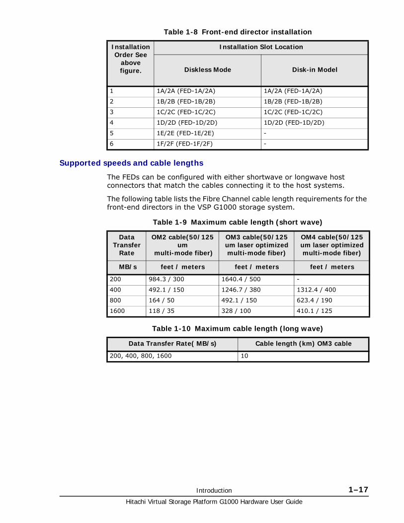
Table 1-8 Front-end director installation
Supported speeds and cable lengths
The FEDs can be configured with either shortwave or longwave host connectors that match the cables connecting it to the host systems.
The following table lists the Fibre Channel cable length requirements for the front-end directors in the VSP G1000 storage system.
Table 1-9 Maximum cable length (short wave)
Table 1-10 Maximum cable length (long wave)
Installation Order See
above figure.
Installation Slot Location
Diskless Mode Disk-in Model
1 1A/2A (FED-1A/2A) 1A/2A (FED-1A/2A)
2 1B/2B (FED-1B/2B) 1B/2B (FED-1B/2B)
3 1C/2C (FED-1C/2C) 1C/2C (FED-1C/2C)
4 1D/2D (FED-1D/2D) 1D/2D (FED-1D/2D)
5 1E/2E (FED-1E/2E) -
6 1F/2F (FED-1F/2F) -
Data Transfer
Rate
OM2 cable(50/125 um
multi-mode fiber)
OM3 cable(50/125 um laser optimized multi-mode fiber)
OM4 cable(50/125 um laser optimized multi-mode fiber)
MB/s feet / meters feet / meters feet / meters
200 984.3 / 300 1640.4 / 500 -
400 492.1 / 150 1246.7 / 380 1312.4 / 400
800 164 / 50 492.1 / 150 623.4 / 190
1600 118 / 35 328 / 100 410.1 / 125
Data Transfer Rate( MB/s) Cable length (km) OM3 cable
200, 400, 800, 1600 10
Hitachi Virtual Storage Platform G1000 Hardware User Guide
1–18 Introduction
Drive chassisThe VSP G1000 supports three different drive chassis as described below. All components in the drive chassis are configured in redundant pairs to prevent system failure. All components in the drive chassis can be added or replaced while the storage system is in operation. See Table A-2 Drive Specifications on page A-4 for detailed information about he drives in each chassis.
• SFF - a 16U group of eight 2U drive trays, each containing up to 24 vertically mounted 2-1/2-inch HDD and/or SSD drives, for a total of 192 drives per chassis. Each drive tray also contains two redundant power supplies, and two ENC adapters that connect the drives to the controller. The connection to the controller may be direct, or it can be connected through other SFF drive trays. See Figure 4-5 SAS Connection Diagram of Rack-00 (SFF/LFF Standard Model) on page 4-20.
• LFF - a 16U group of eight 2U drive trays, each containing up to 12 horizontally mounted 3-1/2-inch drives, for a total of 96 drives per chassis. Each drive tray also contains two redundant power supplies, and two adapters that are used to connect the drives to the controller. The connection to the controller may be direct, or it can be connected through other LFF drive trays. See Figure 4-5 SAS Connection Diagram of Rack-00 (SFF/LFF Standard Model) on page 4-20.
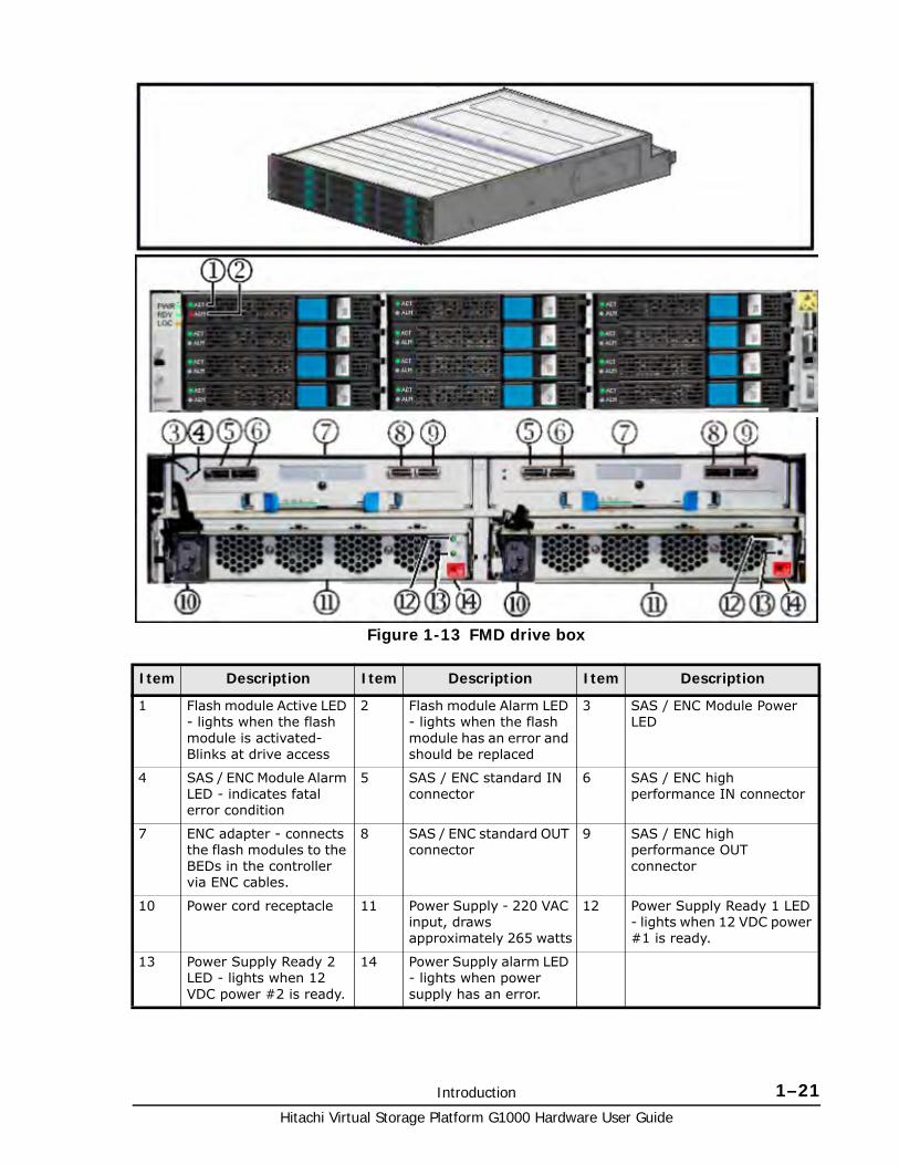
• FMD - an 8U group of four 2U drive trays, each containing up to 12 horizontally mounted 5-1/4-inch Hitachi flash module drives, with a total of 48 drives per chassis. Each drive tray also contains two redundant power supplies and two adapters that connect the drives to the controller. The connection to the controller may be direct, or it can be connected through other FMD drive trays. See Figure 4-7 SAS Connection Diagram of Rack-00 (FBX Standard Model) on page 4-22.
The following illustrations show the front and rear panels of the three types of 2U drive trays. The tables following the illustrations describe the main features of each drive tray and the drives they contain.
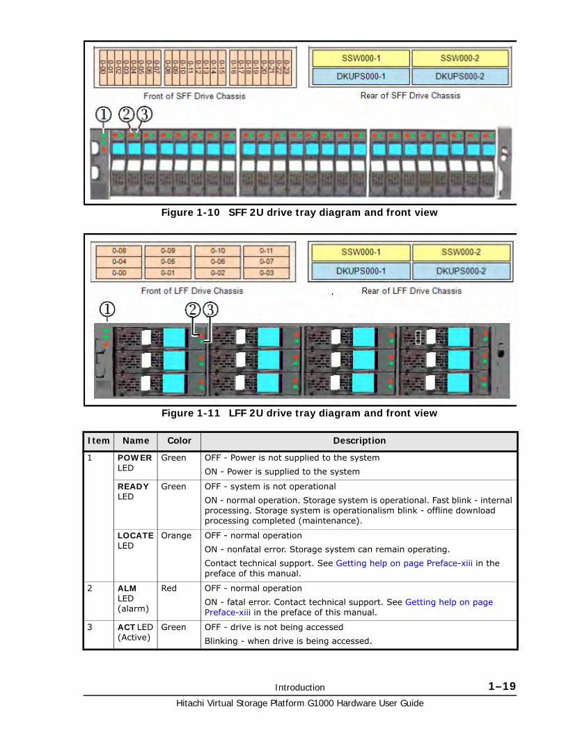
Introduction 1–19Hitachi Virtual Storage Platform G1000 Hardware User Guide
Figure 1-10 SFF 2U drive tray diagram and front view
Figure 1-11 LFF 2U drive tray diagram and front view
Item Name Color Description
1 POWER LED
Green OFF - Power is not supplied to the system
ON - Power is supplied to the system
READY LED
Green OFF - system is not operational
ON - normal operation. Storage system is operational. Fast blink - internal processing. Storage system is operationalism blink - offline download processing completed (maintenance).
LOCATE LED
Orange OFF - normal operation
ON - nonfatal error. Storage system can remain operating.
Contact technical support. See Getting help on page Preface-xiii in the preface of this manual.
2 ALM LED (alarm)
Red OFF - normal operation
ON - fatal error. Contact technical support. See Getting help on page Preface-xiii in the preface of this manual.
3 ACT LED (Active)
Green OFF - drive is not being accessed
Blinking - when drive is being accessed.
Hitachi Virtual Storage Platform G1000 Hardware User Guide
1–20 Introduction
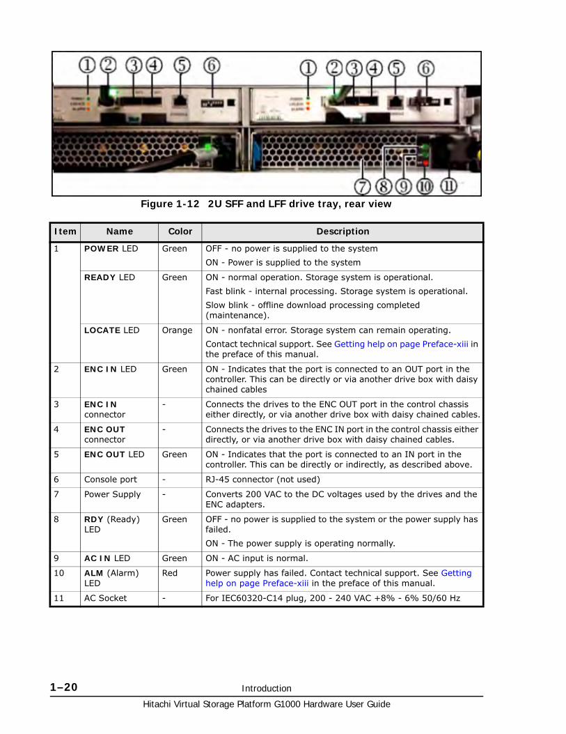
Figure 1-12 2U SFF and LFF drive tray, rear view
Item Name Color Description
1 POWER LED Green OFF - no power is supplied to the system
ON - Power is supplied to the system
READY LED Green ON - normal operation. Storage system is operational.
Fast blink - internal processing. Storage system is operational.
Slow blink - offline download processing completed (maintenance).
LOCATE LED Orange ON - nonfatal error. Storage system can remain operating.
Contact technical support. See Getting help on page Preface-xiii in the preface of this manual.
2 ENC IN LED Green ON - Indicates that the port is connected to an OUT port in the controller. This can be directly or via another drive box with daisy chained cables
3 ENC IN connector
- Connects the drives to the ENC OUT port in the control chassis either directly, or via another drive box with daisy chained cables.
4 ENC OUT connector
- Connects the drives to the ENC IN port in the control chassis either directly, or via another drive box with daisy chained cables.
5 ENC OUT LED Green ON - Indicates that the port is connected to an IN port in the controller. This can be directly or indirectly, as described above.
6 Console port - RJ-45 connector (not used)
7 Power Supply - Converts 200 VAC to the DC voltages used by the drives and the ENC adapters.
8 RDY (Ready) LED
Green OFF - no power is supplied to the system or the power supply has failed.
ON - The power supply is operating normally.
9 AC IN LED Green ON - AC input is normal.
10 ALM (Alarm) LED
Red Power supply has failed. Contact technical support. See Getting help on page Preface-xiii in the preface of this manual.
11 AC Socket - For IEC60320-C14 plug, 200 - 240 VAC +8% - 6% 50/60 Hz
Introduction 1–21Hitachi Virtual Storage Platform G1000 Hardware User Guide
Figure 1-13 FMD drive box
Item Description Item Description Item Description
1 Flash module Active LED - lights when the flash module is activated- Blinks at drive access
2 Flash module Alarm LED - lights when the flash module has an error and should be replaced
3 SAS / ENC Module Power LED
4 SAS / ENC Module Alarm LED - indicates fatal error condition
5 SAS / ENC standard IN connector
6 SAS / ENC high performance IN connector
7 ENC adapter - connects the flash modules to the BEDs in the controller via ENC cables.
8 SAS / ENC standard OUT connector
9 SAS / ENC high performance OUT connector
10 Power cord receptacle 11 Power Supply - 220 VAC input, draws approximately 265 watts
12 Power Supply Ready 1 LED - lights when 12 VDC power #1 is ready.
13 Power Supply Ready 2 LED - lights when 12 VDC power #2 is ready.
14 Power Supply alarm LED - lights when power supply has an error.
Hitachi Virtual Storage Platform G1000 Hardware User Guide
1–22 Introduction
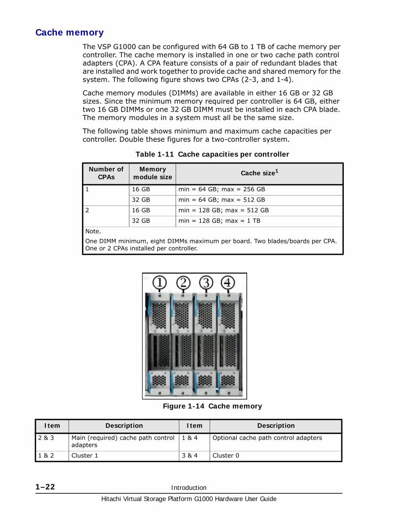
Cache memoryThe VSP G1000 can be configured with 64 GB to 1 TB of cache memory per controller. The cache memory is installed in one or two cache path control adapters (CPA). A CPA feature consists of a pair of redundant blades that are installed and work together to provide cache and shared memory for the system. The following figure shows two CPAs (2-3, and 1-4).
Cache memory modules (DIMMs) are available in either 16 GB or 32 GB sizes. Since the minimum memory required per controller is 64 GB, either two 16 GB DIMMs or one 32 GB DIMM must be installed in each CPA blade. The memory modules in a system must all be the same size.
The following table shows minimum and maximum cache capacities per controller. Double these figures for a two-controller system.
Table 1-11 Cache capacities per controller
Number of CPAs
Memory module size Cache size1
1 16 GB min = 64 GB; max = 256 GB
32 GB min = 64 GB; max = 512 GB
2 16 GB min = 128 GB; max = 512 GB
32 GB min = 128 GB; max = 1 TB
Note.
One DIMM minimum, eight DIMMs maximum per board. Two blades/boards per CPA. One or 2 CPAs installed per controller.
Figure 1-14 Cache memory
Item Description Item Description
2 & 3 Main (required) cache path control adapters
1 & 4 Optional cache path control adapters
1 & 2 Cluster 1 3 & 4 Cluster 0
Introduction 1–23Hitachi Virtual Storage Platform G1000 Hardware User Guide
Memory operation
The VSP G1000 places all read and write data in the cache. The amount of fast-write data in cache is dynamically managed by the cache control algorithms to provide the optimum amount of read and write cache, depending on the workload read and write I/O characteristics.
Data protection
The VSP G1000 is designed so that it cannot lose data or configuration information from the cache if the power fails. The cache is kept alive for up to 32 minutes by the cache backup batteries while the system configuration and data are copied to the cache flash memory (SSD) in the cache backup modules. This is explained in detail in Cache flash memory on page 1-25, and in Battery backup operations on page 5-7.
Cache capacity
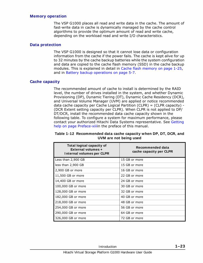
The recommended amount of cache to install is determined by the RAID level, the number of drives installed in the system, and whether Dynamic Provisioning (DP), Dynamic Tiering (DT), Dynamic Cache Residency (DCR), and Universal Volume Manager (UVM) are applied or notice recommended data cache capacity per Cache Logical Partition (CLPR) = (CLPR capacity) - (DCR Extent setting capacity per CLPR). When CLPR is not applied to DP/DT/DCR, install the recommended data cache capacity shown in the following table. To configure a system for maximum performance, please contact your authorized Hitachi Data Systems representative. See Getting help on page Preface-xiiiin the preface of this manual.
Table 1-12 Recommended data cache capacity when DP, DT, DCR, and UVM are not being used
Total logical capacity ofExternal volumes +
Internal volumes per CLPR
Recommended datacache capacity per CLPR
Less than 2,900 GB 15 GB or more
less than 2,900 GB 15 GB or more
2,900 GB or more 16 GB or more
11,500 GB or more 22 GB or more
14,400 GB or more 24 GB or more
100,000 GB or more 30 GB or more
128,000 GB or more 32 GB or more
182,000 GB or more 40 GB or more
218,000 GB or more 48 GB or more
254,000 GB or more 56 GB or more
290,000 GB or more 64 GB or more
326,000 GB or more 72 GB or more
Hitachi Virtual Storage Platform G1000 Hardware User Guide
1–24 Introduction
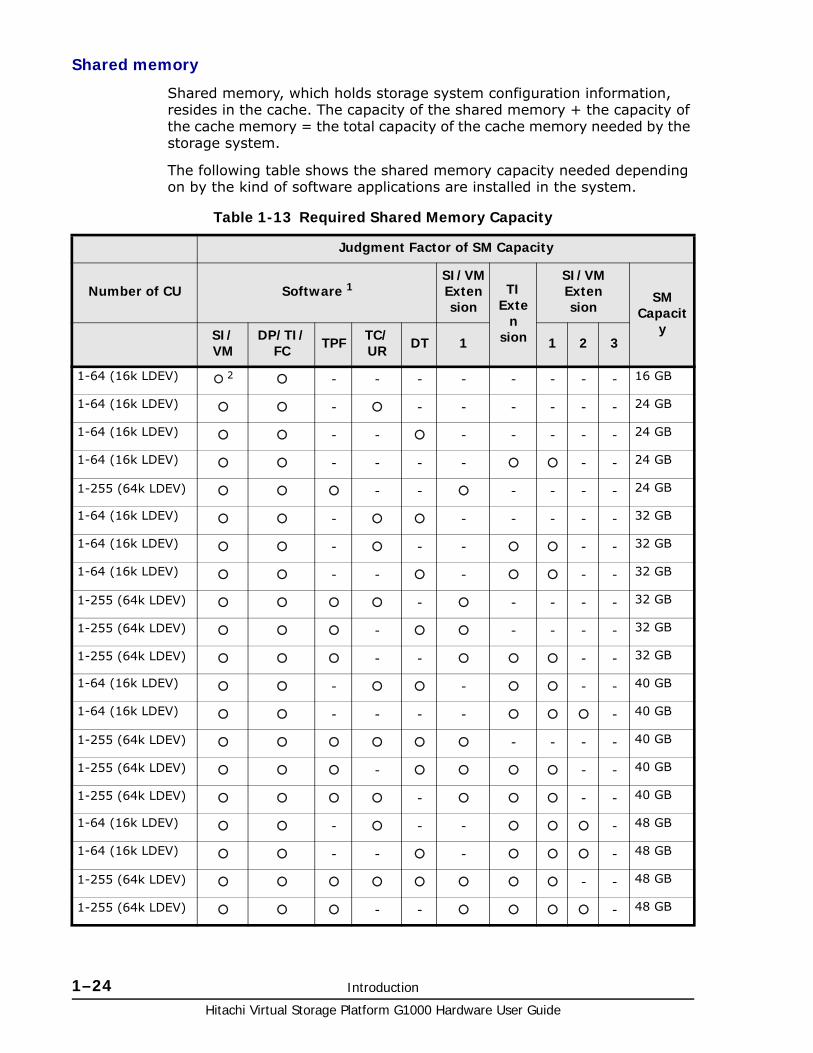
Shared memory
Shared memory, which holds storage system configuration information, resides in the cache. The capacity of the shared memory + the capacity of the cache memory = the total capacity of the cache memory needed by the storage system.
The following table shows the shared memory capacity needed depending on by the kind of software applications are installed in the system.
Table 1-13 Required Shared Memory Capacity
Judgment Factor of SM Capacity
Number of CU Software 1SI/VM Extension
TIExte
nsion
SI/VM Extension
SM Capacit
ySI/VM
DP/TI/FC TPF TC/
UR DT 1 1 2 3
1-64 (16k LDEV) 2 - - - - - - - - 16 GB
1-64 (16k LDEV) - - - - - - - 24 GB
1-64 (16k LDEV) - - - - - - - 24 GB
1-64 (16k LDEV) - - - - - - 24 GB
1-255 (64k LDEV) - - - - - - 24 GB
1-64 (16k LDEV) - - - - - - 32 GB
1-64 (16k LDEV) - - - - - 32 GB
1-64 (16k LDEV) - - - - - 32 GB
1-255 (64k LDEV) - - - - - 32 GB
1-255 (64k LDEV) - - - - - 32 GB
1-255 (64k LDEV) - - - - 32 GB
1-64 (16k LDEV) - - - - 40 GB
1-64 (16k LDEV) - - - - - 40 GB
1-255 (64k LDEV) - - - - 40 GB
1-255 (64k LDEV) - - - 40 GB
1-255 (64k LDEV) - - - 40 GB
1-64 (16k LDEV) - - - - 48 GB
1-64 (16k LDEV) - - - - 48 GB
1-255 (64k LDEV) - - 48 GB
1-255 (64k LDEV) - - - 48 GB
Introduction 1–25Hitachi Virtual Storage Platform G1000 Hardware User Guide
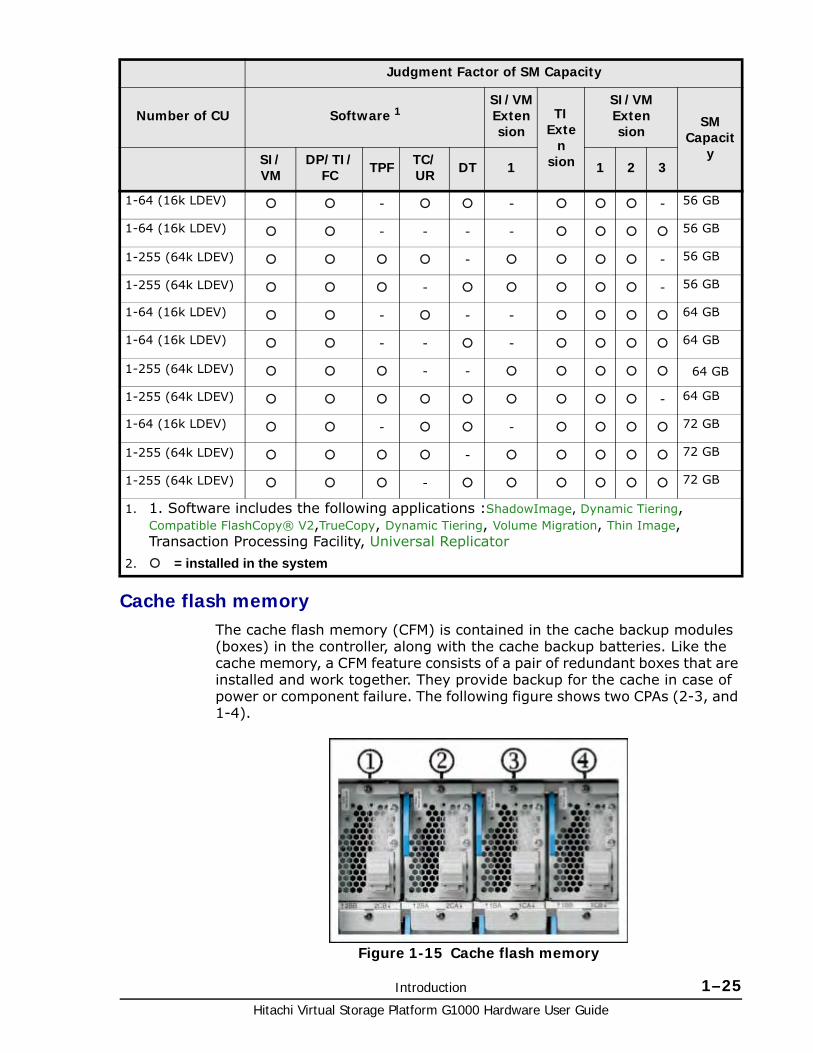
Cache flash memoryThe cache flash memory (CFM) is contained in the cache backup modules (boxes) in the controller, along with the cache backup batteries. Like the cache memory, a CFM feature consists of a pair of redundant boxes that are installed and work together. They provide backup for the cache in case of power or component failure. The following figure shows two CPAs (2-3, and 1-4).
1-64 (16k LDEV) - - - 56 GB
1-64 (16k LDEV) - - - - 56 GB
1-255 (64k LDEV) - - 56 GB
1-255 (64k LDEV) - - 56 GB
1-64 (16k LDEV) - - - 64 GB
1-64 (16k LDEV) - - - 64 GB
1-255 (64k LDEV) - - 64 GB
1-255 (64k LDEV) - 64 GB
1-64 (16k LDEV) - - 72 GB
1-255 (64k LDEV) - 72 GB
1-255 (64k LDEV) - 72 GB
1. 1. Software includes the following applications :ShadowImage, Dynamic Tiering, Compatible FlashCopy® V2,TrueCopy, Dynamic Tiering, Volume Migration, Thin Image, Transaction Processing Facility, Universal Replicator
2. = installed in the system
Judgment Factor of SM Capacity
Number of CU Software 1SI/VM Extension
TIExte
nsion
SI/VM Extension
SM Capacit
ySI/VM
DP/TI/FC TPF TC/
UR DT 1 1 2 3
Figure 1-15 Cache flash memory
Hitachi Virtual Storage Platform G1000 Hardware User Guide
1–26 Introduction
CFM operation
Each CFM blade is connected directly to it’s corresponding CPA blade and backs up the data in that CPA blade if power fails. When data that is not already stored on disk is written to the cache, it is write to one blade of the CPA and mirrored to the other. If one CFM box fails, or one phase of the power fails, the other CMF box backs up the mirrored data from its corresponding CPA blade, and no data is lost. In the unlikely event where a CFM box has failed and a full power failure occurs, the other CFM box backs up the mirrored data from the CPA and no data is lost.
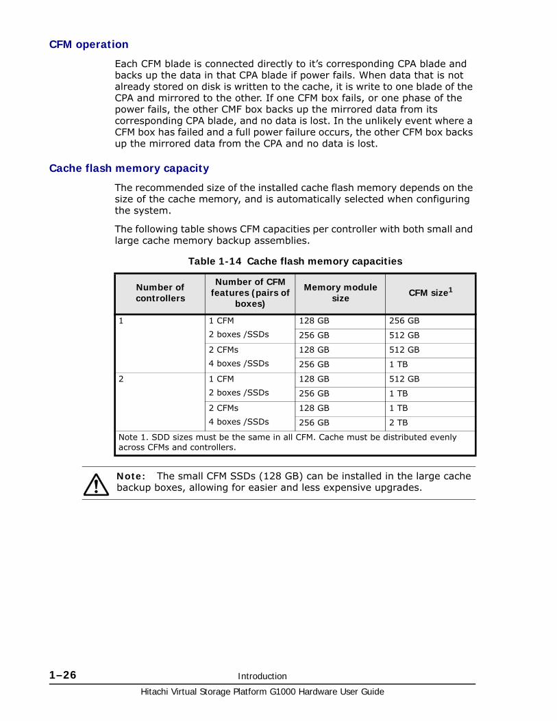
Cache flash memory capacity
The recommended size of the installed cache flash memory depends on the size of the cache memory, and is automatically selected when configuring the system.
The following table shows CFM capacities per controller with both small and large cache memory backup assemblies.
Table 1-14 Cache flash memory capacities
Number of controllers
Number of CFM features (pairs of
boxes)
Memory module size CFM size1
1 1 CFM
2 boxes /SSDs
128 GB 256 GB
256 GB 512 GB
2 CFMs
4 boxes /SSDs
128 GB 512 GB
256 GB 1 TB
2 1 CFM
2 boxes /SSDs
128 GB 512 GB
256 GB 1 TB
2 CFMs
4 boxes /SSDs
128 GB 1 TB
256 GB 2 TB
Note 1. SDD sizes must be the same in all CFM. Cache must be distributed evenly across CFMs and controllers.
Note: The small CFM SSDs (128 GB) can be installed in the large cache backup boxes, allowing for easier and less expensive upgrades.

2
Hardware architecture 2–1Hitachi Virtual Storage Platform G1000 Hardware User Guide
Hardware architecture
This chapter briefly describes the Hitachi Unified Storage VM system architecture, including some of the functional and operational characteristics.
□ System architecture overview
□ Hardware architecture
□ VSP G1000 RAID implementation
□ CU images, LVIs, and logical units
□ Mainframe operations
□ Systems operations
□ Host modes and host mode options
□ Device Manager - Storage Navigator

Hitachi Virtual Storage Platform G1000 Hardware User Guide
2–2 Hardware architecture
System architecture overviewThis section briefly describes the architecture of the Hitachi Virtual Storage Platform G1000 storage system.
Hardware architectureThe basic system architecture of a single controller is shown in the following diagram.
In this architecture, the virtual storage directors (microprocessors) are shared across the cache, front-end directors (host adapters), and back-end directors (disk adapters), providing processing power where and when it is needed, without wait time or interruption. This significantly increases the I/O throughput, up to three times the speed of the VSP system. The system provides a highly granular upgrade path, allowing the addition of drives to the drive chassis, and components such as virtual storage directors to the controller chassis as storage needs increase.
Figure 2-1 VSP G1000 Architecture Overview
Hardware architecture 2–3Hitachi Virtual Storage Platform G1000 Hardware User Guide
VSP G1000 RAID implementationThis section provides an overview of the implementation of RAID technology used on the Hitachi Unified Storage VM storage system.
The objectives of RAID technology are low cost, high reliability, and high I/O performance of data storage devices. To achieve these objectives, this storage system supports RAID levels 1, 5 and 6. RAID level 3 is partly explained to make the outline of RAID5 more understandable, although RAID3 is not supported by the VSP G1000. The features of the levels of RAID technologies are described below.
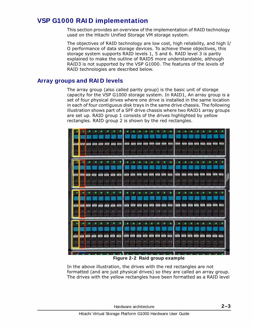
Array groups and RAID levelsThe array group (also called parity group) is the basic unit of storage capacity for the VSP G1000 storage system. In RAID1, An array group is a set of four physical drives where one drive is installed in the same location in each of four contiguous disk trays in the same drive chassis. The following illustration shows part of a SFF drive chassis where two RAID1 array groups are set up. RAID group 1 consists of the drives highlighted by yellow rectangles. RAID group 2 is shown by the red rectangles.
In the above illustration, the drives with the red rectangles are not formatted (and are just physical drives) so they are called an array group. The drives with the yellow rectangles have been formatted as a RAID level
Figure 2-2 Raid group example
Hitachi Virtual Storage Platform G1000 Hardware User Guide
2–4 Hardware architecture
and have initial parity data on them, so they are called a parity group. But in the field, this technical distinction is often lost, and the terms parity group and array group are often used interchangeably.
The VSP G1000 supports the following RAID levels: RAID1, RAID5, and RAID6. RAID0 is not supported on the VSP G1000. When configured in four-drive RAID5 parity groups (3D+1P), three-fourths of the raw capacity is available to store user data, and one fourth of the raw capacity is used for parity data.
RAID1
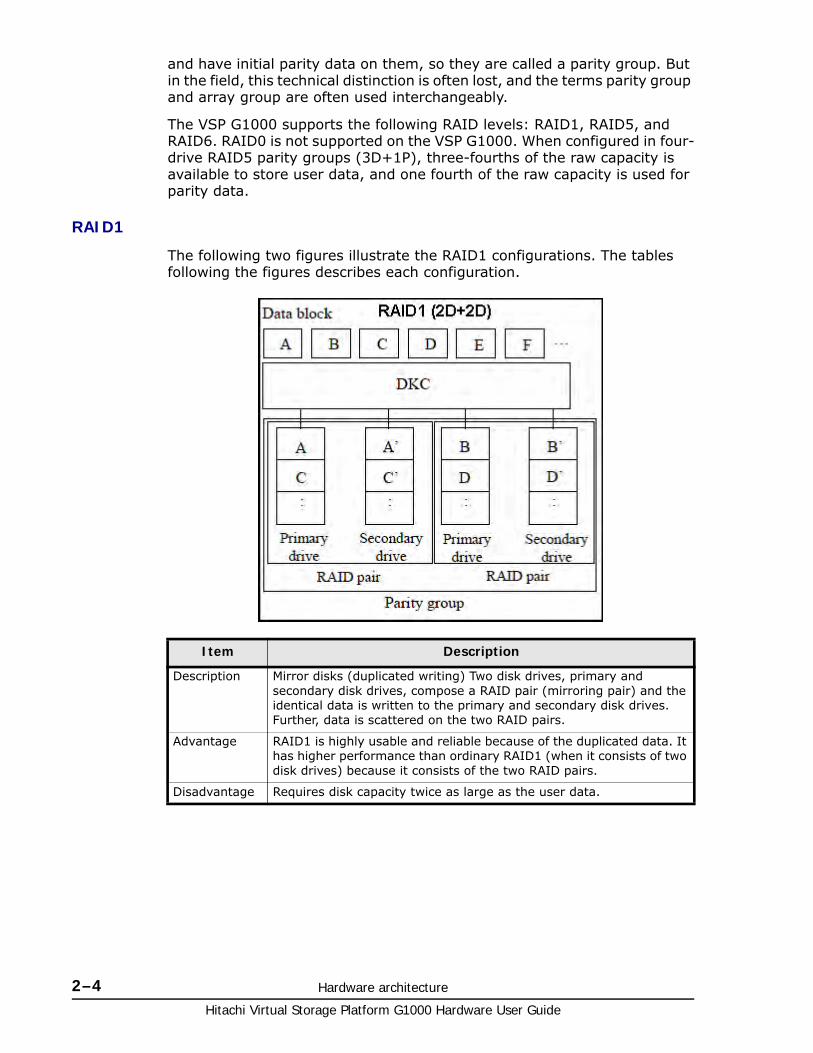
The following two figures illustrate the RAID1 configurations. The tables following the figures describes each configuration.
Item Description
Description Mirror disks (duplicated writing) Two disk drives, primary and secondary disk drives, compose a RAID pair (mirroring pair) and the identical data is written to the primary and secondary disk drives. Further, data is scattered on the two RAID pairs.
Advantage RAID1 is highly usable and reliable because of the duplicated data. It has higher performance than ordinary RAID1 (when it consists of two disk drives) because it consists of the two RAID pairs.
Disadvantage Requires disk capacity twice as large as the user data.
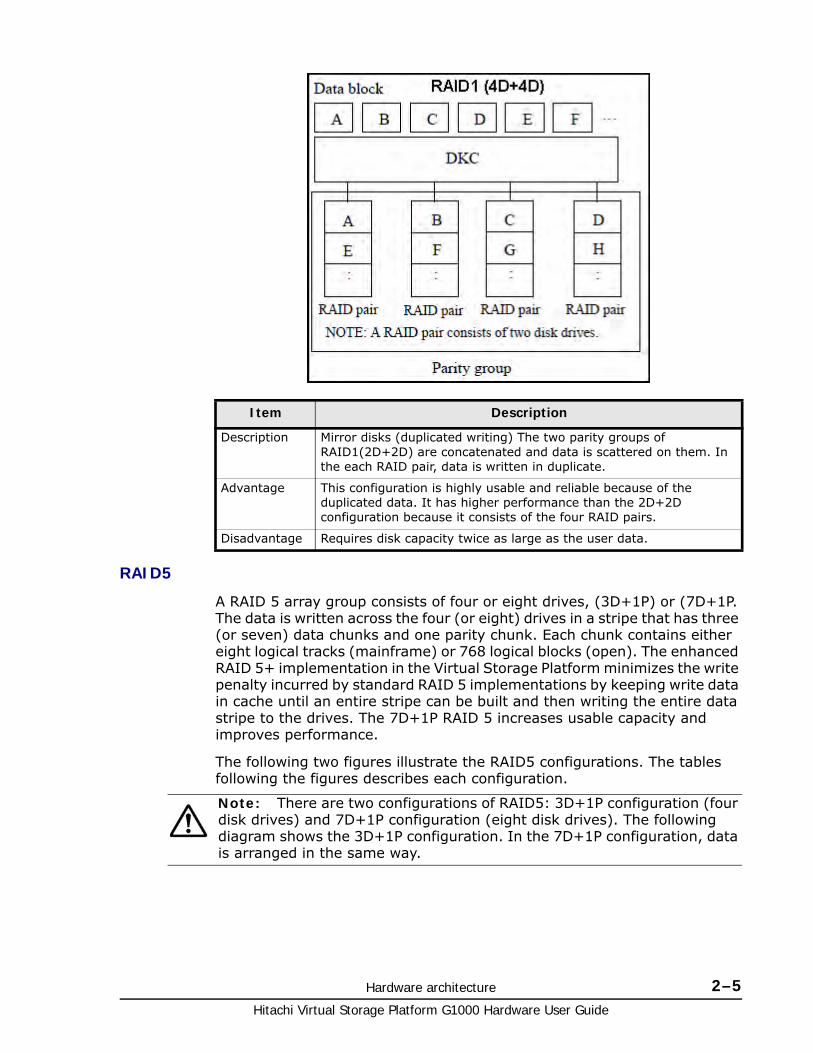
Hardware architecture 2–5Hitachi Virtual Storage Platform G1000 Hardware User Guide
RAID5
A RAID 5 array group consists of four or eight drives, (3D+1P) or (7D+1P. The data is written across the four (or eight) drives in a stripe that has three (or seven) data chunks and one parity chunk. Each chunk contains either eight logical tracks (mainframe) or 768 logical blocks (open). The enhanced RAID 5+ implementation in the Virtual Storage Platform minimizes the write penalty incurred by standard RAID 5 implementations by keeping write data in cache until an entire stripe can be built and then writing the entire data stripe to the drives. The 7D+1P RAID 5 increases usable capacity and improves performance.
The following two figures illustrate the RAID5 configurations. The tables following the figures describes each configuration.
Item Description
Description Mirror disks (duplicated writing) The two parity groups of RAID1(2D+2D) are concatenated and data is scattered on them. In the each RAID pair, data is written in duplicate.
Advantage This configuration is highly usable and reliable because of the duplicated data. It has higher performance than the 2D+2D configuration because it consists of the four RAID pairs.
Disadvantage Requires disk capacity twice as large as the user data.
Note: There are two configurations of RAID5: 3D+1P configuration (four disk drives) and 7D+1P configuration (eight disk drives). The following diagram shows the 3D+1P configuration. In the 7D+1P configuration, data is arranged in the same way.
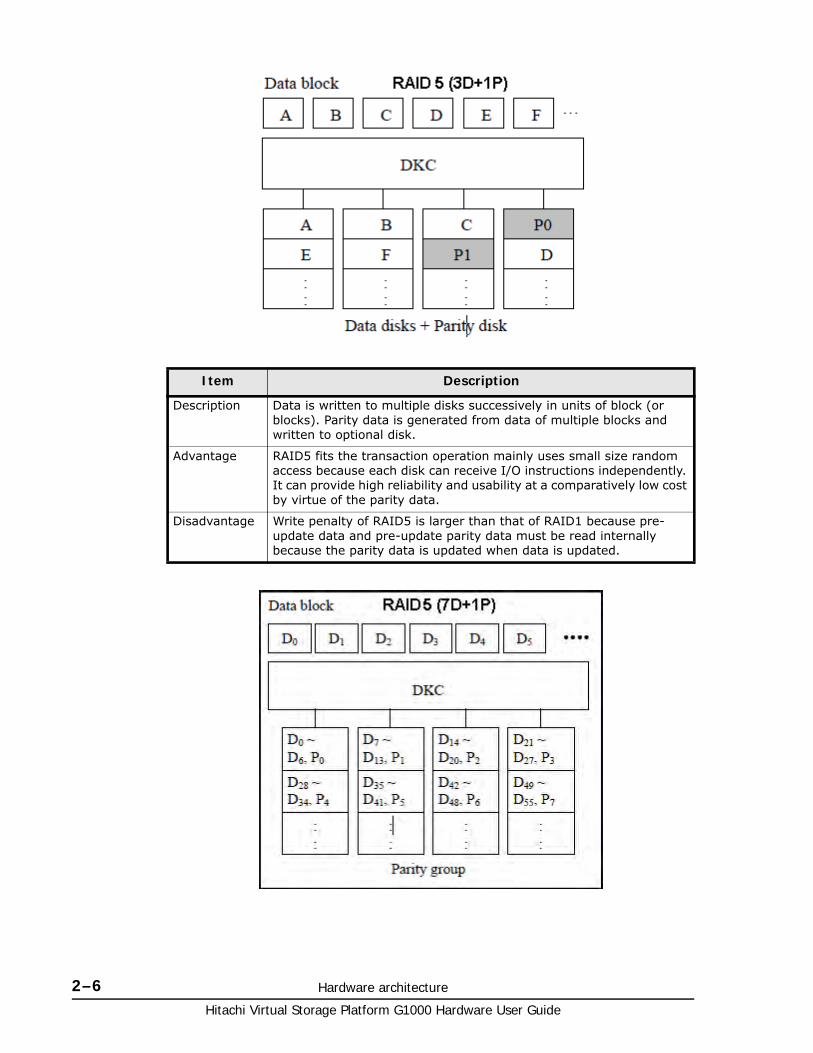
Hitachi Virtual Storage Platform G1000 Hardware User Guide
2–6 Hardware architecture
Item Description
Description Data is written to multiple disks successively in units of block (or blocks). Parity data is generated from data of multiple blocks and written to optional disk.
Advantage RAID5 fits the transaction operation mainly uses small size random access because each disk can receive I/O instructions independently. It can provide high reliability and usability at a comparatively low cost by virtue of the parity data.
Disadvantage Write penalty of RAID5 is larger than that of RAID1 because pre-update data and pre-update parity data must be read internally because the parity data is updated when data is updated.
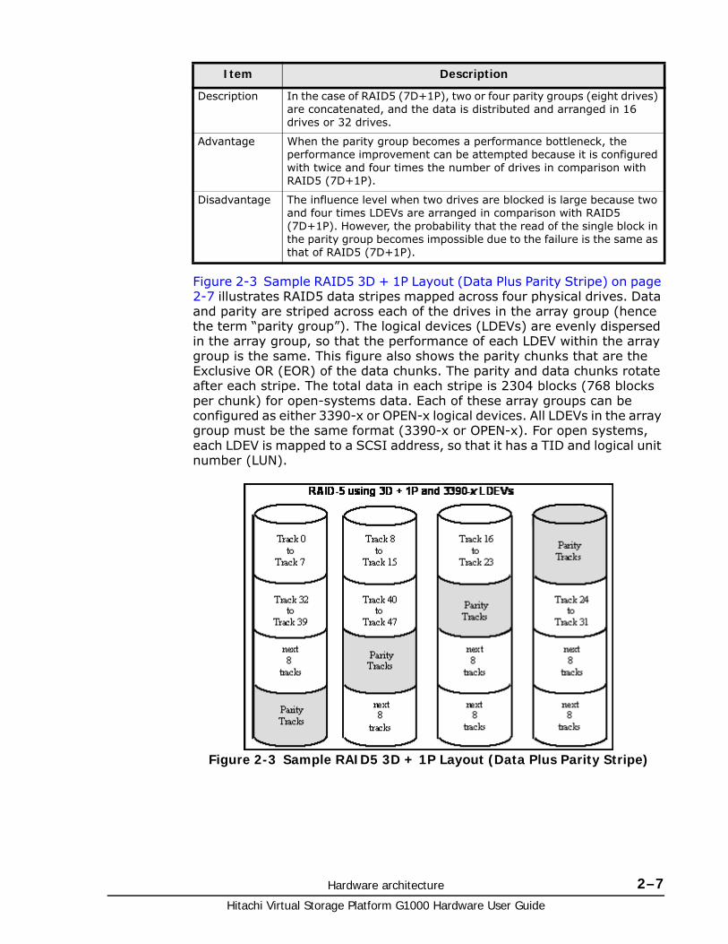
Hardware architecture 2–7Hitachi Virtual Storage Platform G1000 Hardware User Guide
Figure 2-3 Sample RAID5 3D + 1P Layout (Data Plus Parity Stripe) on page 2-7 illustrates RAID5 data stripes mapped across four physical drives. Data and parity are striped across each of the drives in the array group (hence the term “parity group”). The logical devices (LDEVs) are evenly dispersed in the array group, so that the performance of each LDEV within the array group is the same. This figure also shows the parity chunks that are the Exclusive OR (EOR) of the data chunks. The parity and data chunks rotate after each stripe. The total data in each stripe is 2304 blocks (768 blocks per chunk) for open-systems data. Each of these array groups can be configured as either 3390-x or OPEN-x logical devices. All LDEVs in the array group must be the same format (3390-x or OPEN-x). For open systems, each LDEV is mapped to a SCSI address, so that it has a TID and logical unit number (LUN).
Item Description
Description In the case of RAID5 (7D+1P), two or four parity groups (eight drives) are concatenated, and the data is distributed and arranged in 16 drives or 32 drives.
Advantage When the parity group becomes a performance bottleneck, the performance improvement can be attempted because it is configured with twice and four times the number of drives in comparison with RAID5 (7D+1P).
Disadvantage The influence level when two drives are blocked is large because two and four times LDEVs are arranged in comparison with RAID5 (7D+1P). However, the probability that the read of the single block in the parity group becomes impossible due to the failure is the same as that of RAID5 (7D+1P).
Figure 2-3 Sample RAID5 3D + 1P Layout (Data Plus Parity Stripe)
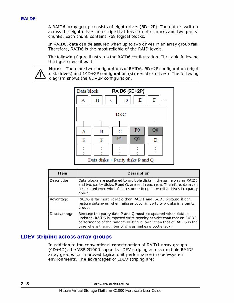
Hitachi Virtual Storage Platform G1000 Hardware User Guide
2–8 Hardware architecture
RAID6
A RAID6 array group consists of eight drives (6D+2P). The data is written across the eight drives in a stripe that has six data chunks and two parity chunks. Each chunk contains 768 logical blocks.
In RAID6, data can be assured when up to two drives in an array group fail. Therefore, RAID6 is the most reliable of the RAID levels.
The following figure illustrates the RAID6 configuration. The table following the figure describes it.
LDEV striping across array groupsIn addition to the conventional concatenation of RAID1 array groups (4D+4D), the VSP G1000 supports LDEV striping across multiple RAID5 array groups for improved logical unit performance in open-system environments. The advantages of LDEV striping are:
Note: There are two configurations of RAID6: 6D+2P configuration (eight disk drives) and 14D+2P configuration (sixteen disk drives). The following diagram shows the 6D+2P configuration.
Item Description
Description Data blocks are scattered to multiple disks in the same way as RAID5 and two parity disks, P and Q, are set in each row. Therefore, data can be assured even when failures occur in up to two disk drives in a parity group.
Advantage RAID6 is far more reliable than RAID1 and RAID5 because it can restore data even when failures occur in up to two disks in a parity group.
Disadvantage Because the parity data P and Q must be updated when data is updated, RAID6 is imposed write penalty heavier than that on RAID5, performance of the random writing is lower than that of RAID5 in the case where the number of drives makes a bottleneck.
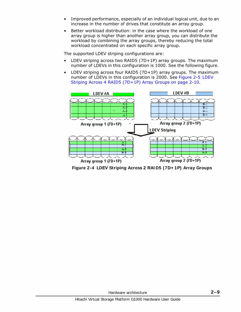
Hardware architecture 2–9Hitachi Virtual Storage Platform G1000 Hardware User Guide
• Improved performance, especially of an individual logical unit, due to an increase in the number of drives that constitute an array group.
• Better workload distribution: in the case where the workload of one array group is higher than another array group, you can distribute the workload by combining the array groups, thereby reducing the total workload concentrated on each specific array group.
The supported LDEV striping configurations are:
• LDEV striping across two RAID5 (7D+1P) array groups. The maximum number of LDEVs in this configuration is 1000. See the following figure.
• LDEV striping across four RAID5 (7D+1P) array groups. The maximum number of LDEVs in this configuration is 2000. See Figure 2-5 LDEV Striping Across 4 RAID5 (7D+1P) Array Groups on page 2-10.
Figure 2-4 LDEV Striping Across 2 RAID5 (7D+1P) Array Groups
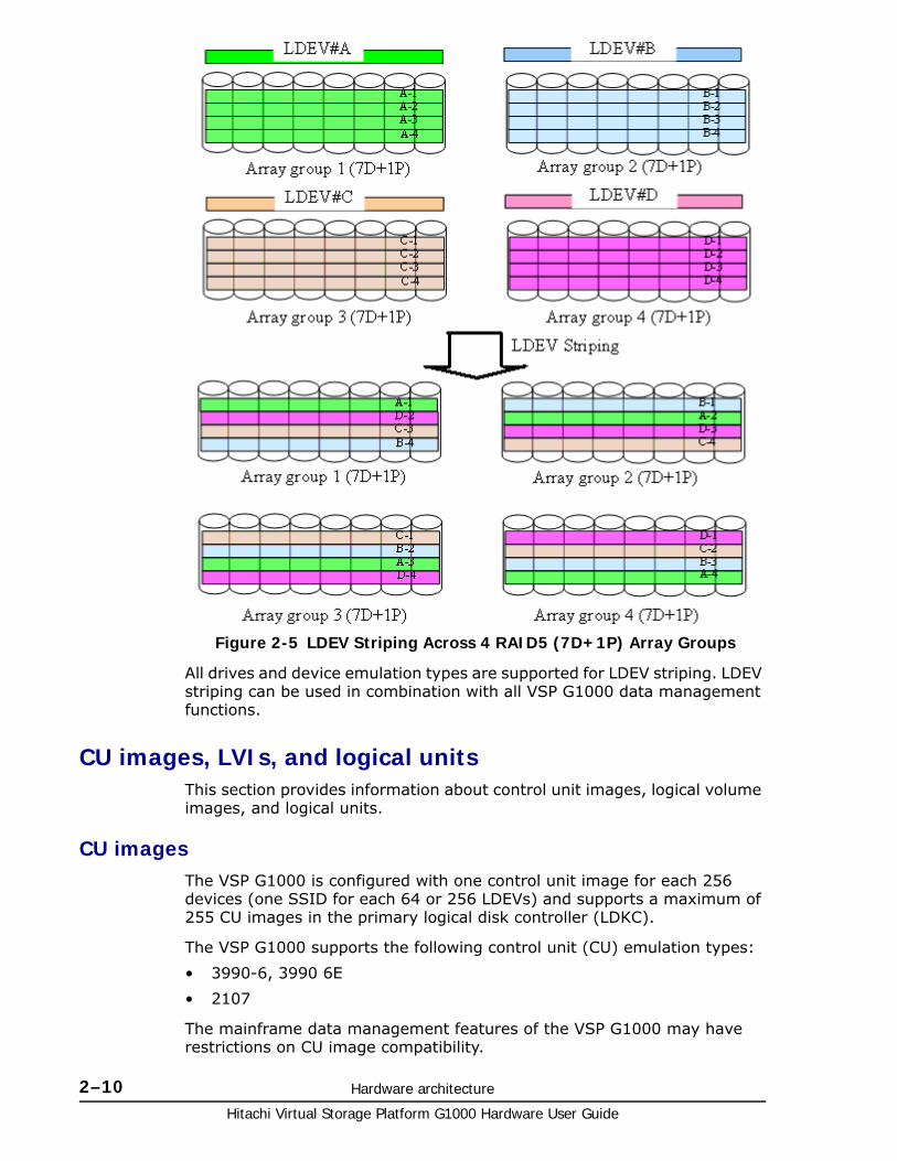
Hitachi Virtual Storage Platform G1000 Hardware User Guide
2–10 Hardware architecture
All drives and device emulation types are supported for LDEV striping. LDEV striping can be used in combination with all VSP G1000 data management functions.
CU images, LVIs, and logical unitsThis section provides information about control unit images, logical volume images, and logical units.
CU imagesThe VSP G1000 is configured with one control unit image for each 256 devices (one SSID for each 64 or 256 LDEVs) and supports a maximum of 255 CU images in the primary logical disk controller (LDKC).
The VSP G1000 supports the following control unit (CU) emulation types:
• 3990-6, 3990 6E
• 2107
The mainframe data management features of the VSP G1000 may have restrictions on CU image compatibility.
Figure 2-5 LDEV Striping Across 4 RAID5 (7D+1P) Array Groups
Hardware architecture 2–11Hitachi Virtual Storage Platform G1000 Hardware User Guide
For further information on CU image support, refer to the Mainframe Host Attachment and Operations Guide, or contact your Hitachi Data Systems account team.
Logical volume imagesThe VSP G1000 supports the following mainframe LVI types:
• 3390-3, -3R, -9, L, and -M. The 3390-3 and 3390-3R LVIs cannot be intermixed in the same storage system.
The LVI configuration of the VSP G1000 storage system depends on the RAID implementation and physical data drive capacities. The LDEVs are accessed using a combination of logical disk controller number (00-01), CU number (00-FE), and device number (00-FF). All control unit images can support an installed LVI range of 00 to FF.
Logical unitsThe VSP G1000 storage system is configured with OPEN-V logical unit types. The OPEN-V logical unit can vary in size from 48.1 MB to 4 TB. For information on other logical unit types (e.g., OPEN-9), contact Hitachi Data Systems support.
For maximum flexibility in logical unit configuration, the VSP G1000 provides the VLL features. Using VLL, users can configure multiple logical units under a single LDEV. Using Virtual LVI, users can concatenate multiple logical units into large volumes. For further information on VLL and Virtual LVI, see the Hitachi Virtual Storage Platform G1000 Performance Guide and the Provisioning Guide for Open Systems
Mainframe operationsThis section provides high-level descriptions of mainframe compatibility, support, and configuration.
Mainframe compatibility and functionalityIn addition to full System-Managed Storage (SMS) compatibility, the VSP G1000 storage system provides the following functions and support in the mainframe environment:
• Sequential data striping
• Cache fast write (CFW) and DASD fast write (DFW)
• Enhanced dynamic cache management
• Extended count key data (ECKD) commands
• Multiple Allegiance
• Concurrent Copy (CC)
• Peer-to-Peer Remote Copy (PPRC)
• Compatible FlashCopy® V2
• Parallel Access Volume (PAV)
• Enhanced CCW
• Priority I/O queuing
• Red Hat Linux for IBM S/390 and zSeries
Hitachi Virtual Storage Platform G1000 Hardware User Guide
2–12 Hardware architecture
Mainframe operating system supportThe VSP G1000 storage system supports most major IBM Mainframe operating systems and Open System operating systems, such as Microsoft Windows, Oracle Solaris, IBM AIX, Linux, HP-UX, and VMware. For more complete information on the supported operating systems, go to: http://www.hds.com/products/interoperability/index.htm
Mainframe configurationAfter a VSP G1000 storage system has been installed, users can configure the storage system for mainframe operations.
See the following user documents for information and instructions on configuring your VSP G1000 storage system for mainframe operations:
• The Mainframe Host Attachment and Operations Guide, describes and provides instructions for configuring the VSP G1000 for mainframe operations, including FICON attachment, hardware definition, cache operations, and device operations.
For detailed information on FICON connectivity, FICON/Open intermix configurations, and supported HBAs, switches, and directors for VSP G1000, please contact Hitachi Data Systems support.
• The Hitachi Command Suite Installation and Configuration Guide or Hitachi Virtual Storage Platform G1000 Mainframe System Administrator Guide provides instructions for installing, configuring, and using Device Manager - Storage Navigator to perform resource and data management operations on the VSP G1000 storage systems.
• The Provisioning Guide for Mainframe Systems and Hitachi Volume Shredder User Guide, provide instructions for converting single volumes (LVIs) into multiple smaller volumes to improve data access performance.
Systems operationsThis section provides high-level descriptions of VSP G1000 systems compatibility, support, and configuration.
Compatibility and functionalityThe VSP G1000 storage system supports and offers many features and functions for the open-systems environment, including:
• Multi-initiator I/O configurations in which multiple host systems are attached to the same Fibre Channel interface
• Fibre Channel Arbitrated Loop (FC-AL) and fabric topologies
• Command tag queuing
• Industry-standard failover and logical volume management software
• SNMP remote storage system management
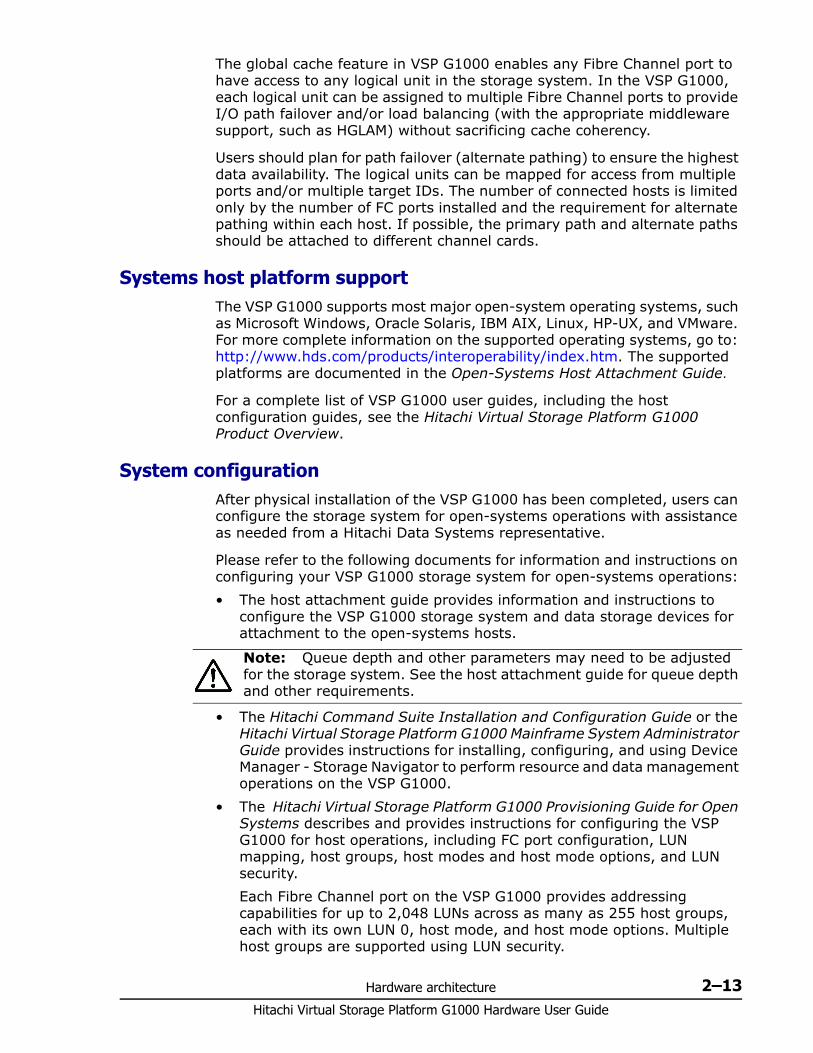
Hardware architecture 2–13Hitachi Virtual Storage Platform G1000 Hardware User Guide
The global cache feature in VSP G1000 enables any Fibre Channel port to have access to any logical unit in the storage system. In the VSP G1000, each logical unit can be assigned to multiple Fibre Channel ports to provide I/O path failover and/or load balancing (with the appropriate middleware support, such as HGLAM) without sacrificing cache coherency.
Users should plan for path failover (alternate pathing) to ensure the highest data availability. The logical units can be mapped for access from multiple ports and/or multiple target IDs. The number of connected hosts is limited only by the number of FC ports installed and the requirement for alternate pathing within each host. If possible, the primary path and alternate paths should be attached to different channel cards.
Systems host platform supportThe VSP G1000 supports most major open-system operating systems, such as Microsoft Windows, Oracle Solaris, IBM AIX, Linux, HP-UX, and VMware. For more complete information on the supported operating systems, go to: http://www.hds.com/products/interoperability/index.htm. The supported platforms are documented in the Open-Systems Host Attachment Guide.
For a complete list of VSP G1000 user guides, including the host configuration guides, see the Hitachi Virtual Storage Platform G1000 Product Overview.
System configurationAfter physical installation of the VSP G1000 has been completed, users can configure the storage system for open-systems operations with assistance as needed from a Hitachi Data Systems representative.
Please refer to the following documents for information and instructions on configuring your VSP G1000 storage system for open-systems operations:
• The host attachment guide provides information and instructions to configure the VSP G1000 storage system and data storage devices for attachment to the open-systems hosts.
• The Hitachi Command Suite Installation and Configuration Guide or the Hitachi Virtual Storage Platform G1000 Mainframe System Administrator Guide provides instructions for installing, configuring, and using Device Manager - Storage Navigator to perform resource and data management operations on the VSP G1000.
• The Hitachi Virtual Storage Platform G1000 Provisioning Guide for Open Systems describes and provides instructions for configuring the VSP G1000 for host operations, including FC port configuration, LUN mapping, host groups, host modes and host mode options, and LUN security.
Each Fibre Channel port on the VSP G1000 provides addressing capabilities for up to 2,048 LUNs across as many as 255 host groups, each with its own LUN 0, host mode, and host mode options. Multiple host groups are supported using LUN security.
Note: Queue depth and other parameters may need to be adjusted for the storage system. See the host attachment guide for queue depth and other requirements.
Hitachi Virtual Storage Platform G1000 Hardware User Guide
2–14 Hardware architecture
• The Hitachi SNMP Agent User Guide describes the SNMP API interface for the VSP G1000 storage systems and provides instructions for configuring and performing SNMP operations.
• The Hitachi Virtual Storage Platform G1000 Provisioning Guide for Open Systems and Hitachi Volume Shredder User Guide provide instructions for configuring multiple custom volumes (logical units) under single LDEVs on the VSP G1000. The Provisioning Guide for Open Systems also provides instructions for configuring size-expanded logical units by concatenating multiple logical units to form individual large logical units.
Host modes and host mode optionsVSP G1000 supports connection of multiple server hosts of different platforms to each of its ports. When your system is configured, the hosts connected to each port are grouped by host group or by target. For example, if Solaris and Windows hosts are connected to separate Fibre Channel ports, or through a switch to a single Fibre Channel port, a host group is created for the Solaris hosts and another host group is created for the Windows hosts. The appropriate host mode and host mode options are assigned to each host group. The host modes and host mode options provide enhanced compatibility with supported platforms and environments.
The host groups, host modes, and host mode options are configured using the LUN Manager software on Device Manager - Storage Navigator. For further information on host groups, host modes, and host mode options, refer to the Hitachi Virtual Storage Platform G1000 Provisioning Guide for Open Systems.
Device Manager - Storage NavigatorDevice Manager - Storage Navigator is the GUI that accesses the features in the firmware and is used to set up and monitor the storage system. It can be installed on a PC, laptop, or workstation. It communicates via a LAN to the SVP in the VSP G1000 storage system. The SVP obtains storage system configuration and status information and sends user-initiated commands to the storage system. The Device Manager - Storage Navigator displays detailed storage system information and allows users to configure and perform storage operations on the system.
Device Manager - Storage Navigator is provided as a Java® applet program that can be executed on any machine that supports a Java Virtual Machine (JVM). A PC hosting the Device Manager - Storage Navigator software is called a remote console. Each time a remote console accesses and logs into the SVP of the desired storage system, the Device Manager - Storage Navigator applet is downloaded from the SVP to the remote console. The following figure illustrates remote console and SVP configuration for Device Manager - Storage Navigator.
For further information about Device Manager - Storage Navigator, see the The Hitachi Command Suite Installation and Configuration Guide or the Hitachi Virtual Storage Platform G1000 Mainframe System Administrator Guide.
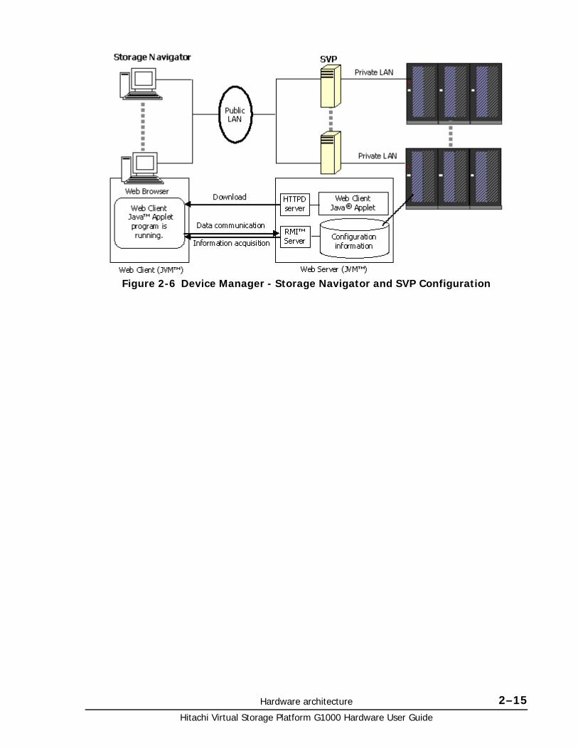
Hardware architecture 2–15Hitachi Virtual Storage Platform G1000 Hardware User Guide
Figure 2-6 Device Manager - Storage Navigator and SVP Configuration

Hitachi Virtual Storage Platform G1000 Hardware User Guide
2–16 Hardware architecture
3
Safety requirements 3–1Hitachi Virtual Storage Platform G1000 Hardware User Guide
Safety requirements
Install Hitachi equipment in accordance with the local safety codes and regulations that apply to the facility. This chapter contains additional safety information that may apply to your facility. Read and follow the safety guidelines in this chapter before installing the equipment. The key sections in this chapter are:
□ General safety guidelines
□ Work safety guidelines
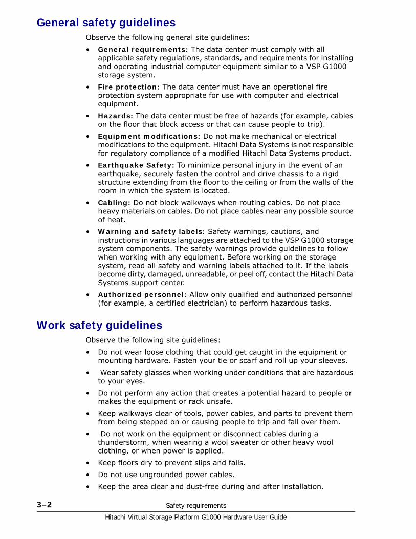
Hitachi Virtual Storage Platform G1000 Hardware User Guide
3–2 Safety requirements
General safety guidelinesObserve the following general site guidelines:
• General requirements: The data center must comply with all applicable safety regulations, standards, and requirements for installing and operating industrial computer equipment similar to a VSP G1000 storage system.
• Fire protection: The data center must have an operational fire protection system appropriate for use with computer and electrical equipment.
• Hazards: The data center must be free of hazards (for example, cables on the floor that block access or that can cause people to trip).
• Equipment modifications: Do not make mechanical or electrical modifications to the equipment. Hitachi Data Systems is not responsible for regulatory compliance of a modified Hitachi Data Systems product.
• Earthquake Safety: To minimize personal injury in the event of an earthquake, securely fasten the control and drive chassis to a rigid structure extending from the floor to the ceiling or from the walls of the room in which the system is located.
• Cabling: Do not block walkways when routing cables. Do not place heavy materials on cables. Do not place cables near any possible source of heat.
• Warning and safety labels: Safety warnings, cautions, and instructions in various languages are attached to the VSP G1000 storage system components. The safety warnings provide guidelines to follow when working with any equipment. Before working on the storage system, read all safety and warning labels attached to it. If the labels become dirty, damaged, unreadable, or peel off, contact the Hitachi Data Systems support center.
• Authorized personnel: Allow only qualified and authorized personnel (for example, a certified electrician) to perform hazardous tasks.
Work safety guidelinesObserve the following site guidelines:
• Do not wear loose clothing that could get caught in the equipment or mounting hardware. Fasten your tie or scarf and roll up your sleeves.
• Wear safety glasses when working under conditions that are hazardous to your eyes.
• Do not perform any action that creates a potential hazard to people or makes the equipment or rack unsafe.
• Keep walkways clear of tools, power cables, and parts to prevent them from being stepped on or causing people to trip and fall over them.
• Do not work on the equipment or disconnect cables during a thunderstorm, when wearing a wool sweater or other heavy wool clothing, or when power is applied.
• Keep floors dry to prevent slips and falls.
• Do not use ungrounded power cables.
• Keep the area clear and dust-free during and after installation.
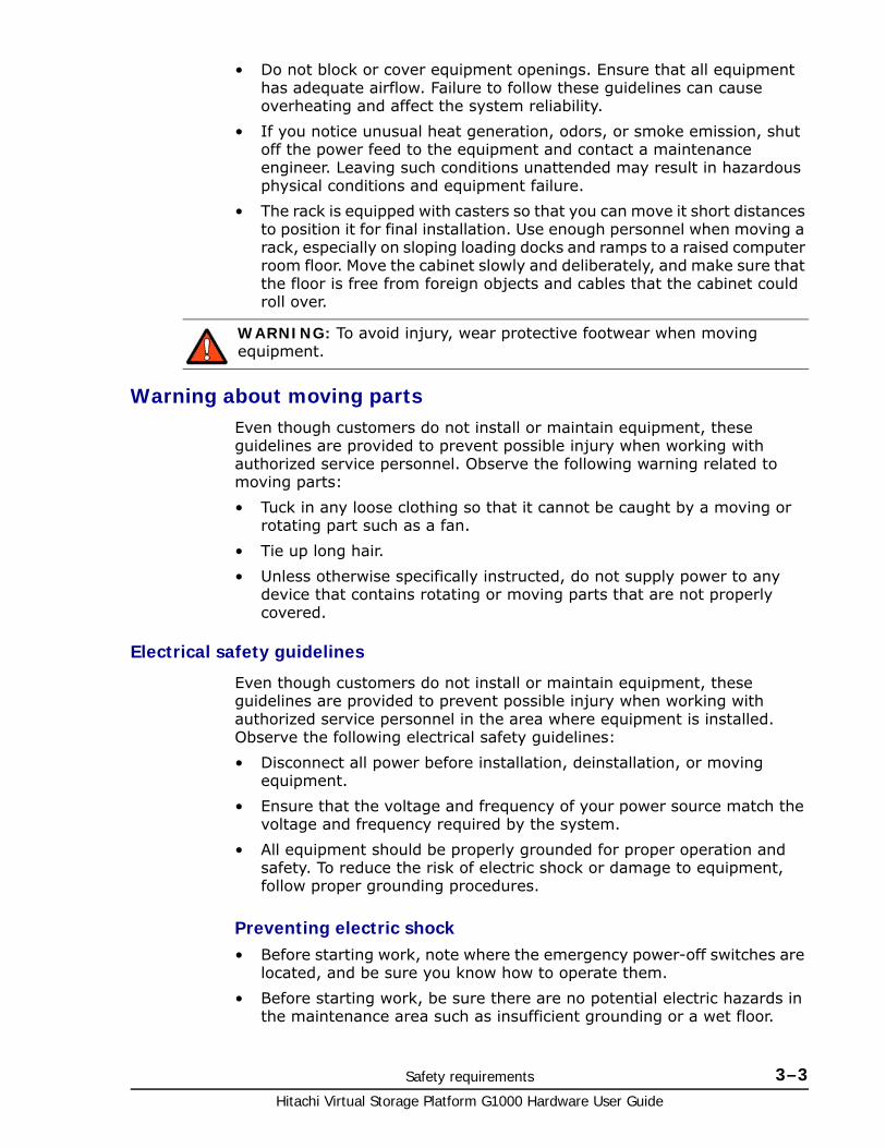
Safety requirements 3–3Hitachi Virtual Storage Platform G1000 Hardware User Guide
• Do not block or cover equipment openings. Ensure that all equipment has adequate airflow. Failure to follow these guidelines can cause overheating and affect the system reliability.
• If you notice unusual heat generation, odors, or smoke emission, shut off the power feed to the equipment and contact a maintenance engineer. Leaving such conditions unattended may result in hazardous physical conditions and equipment failure.
• The rack is equipped with casters so that you can move it short distances to position it for final installation. Use enough personnel when moving a rack, especially on sloping loading docks and ramps to a raised computer room floor. Move the cabinet slowly and deliberately, and make sure that the floor is free from foreign objects and cables that the cabinet could roll over.
Warning about moving partsEven though customers do not install or maintain equipment, these guidelines are provided to prevent possible injury when working with authorized service personnel. Observe the following warning related to moving parts:
• Tuck in any loose clothing so that it cannot be caught by a moving or rotating part such as a fan.
• Tie up long hair.
• Unless otherwise specifically instructed, do not supply power to any device that contains rotating or moving parts that are not properly covered.
Electrical safety guidelines
Even though customers do not install or maintain equipment, these guidelines are provided to prevent possible injury when working with authorized service personnel in the area where equipment is installed. Observe the following electrical safety guidelines:
• Disconnect all power before installation, deinstallation, or moving equipment.
• Ensure that the voltage and frequency of your power source match the voltage and frequency required by the system.
• All equipment should be properly grounded for proper operation and safety. To reduce the risk of electric shock or damage to equipment, follow proper grounding procedures.
Preventing electric shock• Before starting work, note where the emergency power-off switches are
located, and be sure you know how to operate them.
• Before starting work, be sure there are no potential electric hazards in the maintenance area such as insufficient grounding or a wet floor.
WARNING: To avoid injury, wear protective footwear when moving equipment.

Hitachi Virtual Storage Platform G1000 Hardware User Guide
3–4 Safety requirements
4
Site preparation 4–1Hitachi Virtual Storage Platform G1000 Hardware User Guide
Site preparation
This chapter provides site and system requirements and specifications that are needed to plan a Hitachi Virtual Storage Platform G1000 storage system installation and prepare the site where the system will be installed, so that the equipment installation is efficient and trouble-free.
This chapter may not provide all the information needed for every installation. The installation and maintenance documents used by Hitachi Data Systems personnel contain complete information, including specifications for all possible installations. Contact Hitachi Data Systems support if you need information that is not included in this chapter.
□ Safety requirements
□ Responsibilities
□ Site Preparation checklist
□ General site requirements
□ Data center requirements
□ Operational requirements
□ System specifications and requirements
□ Connection diagrams
□ Service clearance, floor cutout, and floor load rating
Hitachi Virtual Storage Platform G1000 Hardware User Guide
4–2 Site preparation
Safety requirements
ResponsibilitiesThe responsibilities for site planning and preparation are shared by the system users and Hitachi Data Systems support. The required installation planning tasks must be scheduled and completed to ensure successful and efficient installation of the VSP G1000 storage system.
User responsibilitiesYou are responsible for performing the following tasks to prepare your site for installation of the VSP G1000 storage system.
• Understand the applicable safety requirements associated with installing a VSP G1000 storage system.
• Understand the installation requirements for the VSP G1000 storage system. You can use the information in this manual to determine the specific requirements for your installation. As needed, review the Hitachi Virtual Storage Platform G1000 Product Overview Guide to familiarize yourself with the components, features, and functions of the VSP G1000 storage system.
• Verify that the installation site meets all installation requirements. A checklist is included in this section to help you with this task.
• Provide electrical hardware, including cables, connectors and receptacles that are required to connect the VSP G1000 storage system to site power.
• As needed, work with Hitachi Data Systems support to create an installation plan. Allow enough time to complete any changes to the plan, so your site is ready when the equipment arrives.
Hitachi Data Systems responsibilitiesHitachi Data Systems support is responsible for completing the following tasks:
• Assist you as needed during the installation planning process for your specific site and operational configuration
• Coordinate Hitachi Data Systems resources to ensure a successful installation and configuration of the VSP G1000 storage system.
Caution: Before operating or working on the VSP G1000 storage system, read the safety and environmental information in Safety requirements on page 3-1.
Note: The VSP G1000 storage system must be installed by trained Hitachi Data Systems personnel or trained authorized service providers. The VSP G1000 storage system is not a customer-installable product.
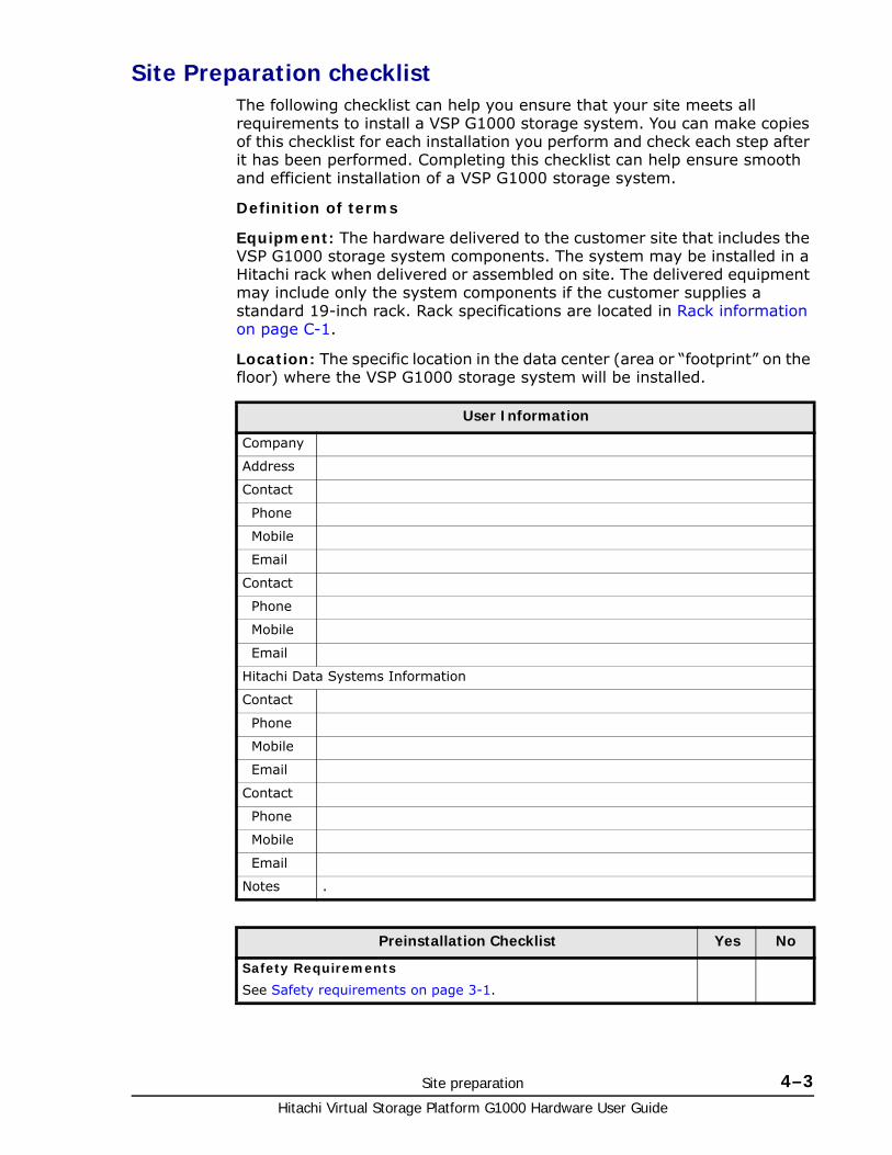
Site preparation 4–3Hitachi Virtual Storage Platform G1000 Hardware User Guide
Site Preparation checklistThe following checklist can help you ensure that your site meets all requirements to install a VSP G1000 storage system. You can make copies of this checklist for each installation you perform and check each step after it has been performed. Completing this checklist can help ensure smooth and efficient installation of a VSP G1000 storage system.
Definition of terms
Equipment: The hardware delivered to the customer site that includes the VSP G1000 storage system components. The system may be installed in a Hitachi rack when delivered or assembled on site. The delivered equipment may include only the system components if the customer supplies a standard 19-inch rack. Rack specifications are located in Rack information on page C-1.
Location: The specific location in the data center (area or “footprint” on the floor) where the VSP G1000 storage system will be installed.
User Information
Company
Address
Contact
Phone
Mobile
Contact
Phone
Mobile
Hitachi Data Systems Information
Contact
Phone
Mobile
Contact
Phone
Mobile
Notes .
Preinstallation Checklist Yes No
Safety Requirements
See Safety requirements on page 3-1.

Hitachi Virtual Storage Platform G1000 Hardware User Guide
4–4 Site preparation
Does the data center provide appropriate fire protection for computer equipment similar to VSP G1000 storage systems?
Is the data center free of hazards such as cables that obstruct access to the equipment?
Delivery Requirements
See General site requirements on page 4-5
Is the receiving area adequate for equipment delivery, unloading, and unpacking?
Are all doors, hallways, elevators, and ramps wide enough and high enough to allow the equipment to be moved from the receiving area to the installation area?
Can the floors, elevators, and ramps support the weight of the equipment? See General site requirements on page 4-5.
Storage Requirements
See System storage requirements on page 4-6.
If the equipment will be stored after delivery and prior to installation, does the storage location meet the environmental requirements for storing a VSP G1000 storage system?
Facilities Requirements
See Data center requirements on page 4-7.
Does the data center have a raised floor?
Does the location meet the requirements for service clearance and cable routing (for example, floor cutouts)? See Equipment clearances on page 4-5.
Does the installation site meet the floor load rating requirements?
Power Requirements
See Electrical specifications on page 4-10.
Does the data center meet the AC input power requirements? See See Electrical specifications on page 4-10, Power connection on page 4-11, and Electrical specifications on page A-6.
Does the data center meet the circuit breaker and plug requirements? See Data center requirements on page 4-7.
Is the customer-supplied hardware such as connectors, receptacles, and cables ready for the installation?
Environmental Requirements
See general Environmental specifications on page 4-12 and detailed Environmental specifications on page A-8.
Does the data center meet the following operational environmental requirements for a VSP G1000 storage system?
temperature
humidity
altitude
air flow
Does the data center provide adequate protection for a VSP G1000 storage system from the following?
Preinstallation Checklist Yes No
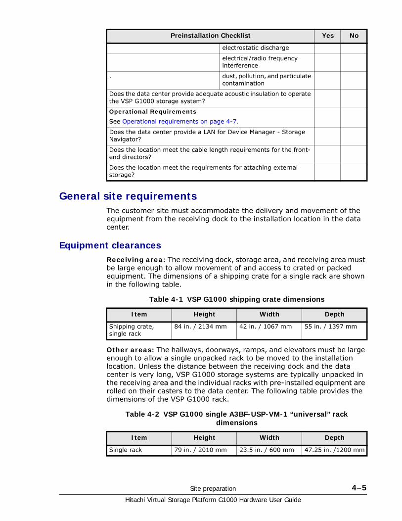
Site preparation 4–5Hitachi Virtual Storage Platform G1000 Hardware User Guide
General site requirementsThe customer site must accommodate the delivery and movement of the equipment from the receiving dock to the installation location in the data center.
Equipment clearancesReceiving area: The receiving dock, storage area, and receiving area must be large enough to allow movement of and access to crated or packed equipment. The dimensions of a shipping crate for a single rack are shown in the following table.
Table 4-1 VSP G1000 shipping crate dimensions
Other areas: The hallways, doorways, ramps, and elevators must be large enough to allow a single unpacked rack to be moved to the installation location. Unless the distance between the receiving dock and the data center is very long, VSP G1000 storage systems are typically unpacked in the receiving area and the individual racks with pre-installed equipment are rolled on their casters to the data center. The following table provides the dimensions of the VSP G1000 rack.
Table 4-2 VSP G1000 single A3BF-USP-VM-1 “universal” rack dimensions
electrostatic discharge
electrical/radio frequency interference
. dust, pollution, and particulate contamination
Does the data center provide adequate acoustic insulation to operate the VSP G1000 storage system?
Operational Requirements
See Operational requirements on page 4-7.
Does the data center provide a LAN for Device Manager - Storage Navigator?
Does the location meet the cable length requirements for the front-end directors?
Does the location meet the requirements for attaching external storage?
Preinstallation Checklist Yes No
Item Height Width Depth
Shipping crate, single rack
84 in. / 2134 mm 42 in. / 1067 mm 55 in. / 1397 mm
Item Height Width Depth
Single rack 79 in. / 2010 mm 23.5 in. / 600 mm 47.25 in. /1200 mm
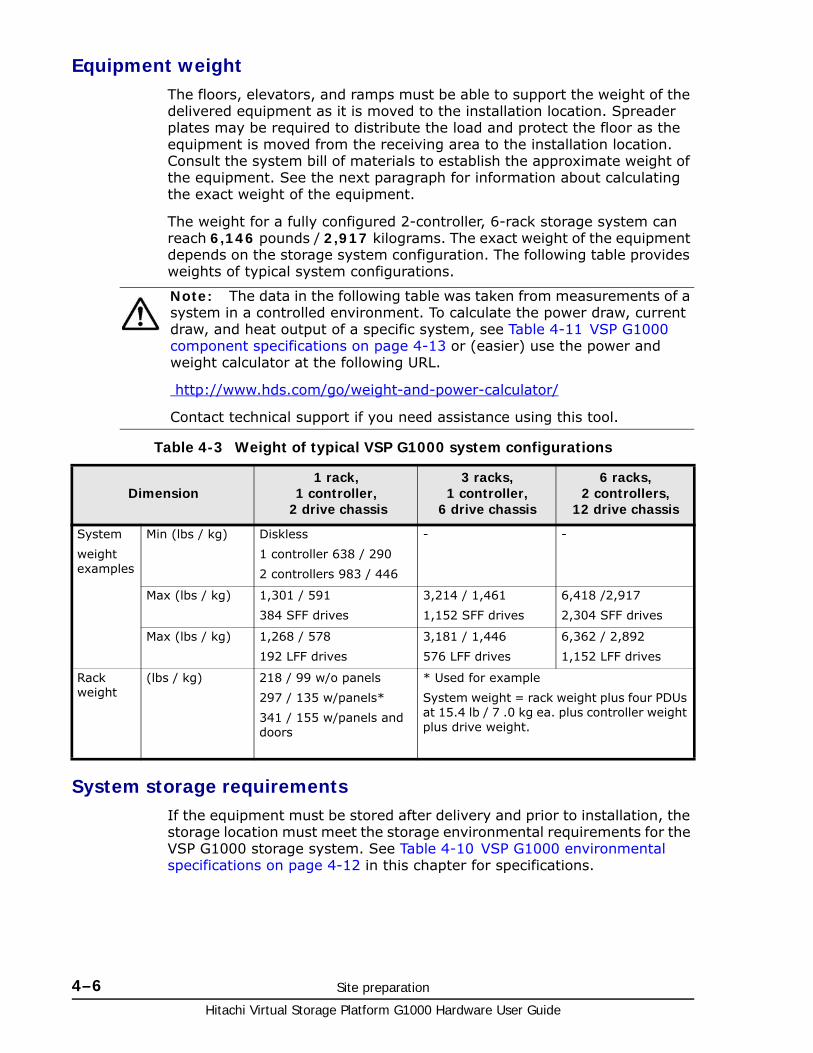
Hitachi Virtual Storage Platform G1000 Hardware User Guide
4–6 Site preparation
Equipment weightThe floors, elevators, and ramps must be able to support the weight of the delivered equipment as it is moved to the installation location. Spreader plates may be required to distribute the load and protect the floor as the equipment is moved from the receiving area to the installation location. Consult the system bill of materials to establish the approximate weight of the equipment. See the next paragraph for information about calculating the exact weight of the equipment.
The weight for a fully configured 2-controller, 6-rack storage system can reach 6,146 pounds / 2,917 kilograms. The exact weight of the equipment depends on the storage system configuration. The following table provides weights of typical system configurations.
Table 4-3 Weight of typical VSP G1000 system configurations
System storage requirementsIf the equipment must be stored after delivery and prior to installation, the storage location must meet the storage environmental requirements for the VSP G1000 storage system. See Table 4-10 VSP G1000 environmental specifications on page 4-12 in this chapter for specifications.
Note: The data in the following table was taken from measurements of a system in a controlled environment. To calculate the power draw, current draw, and heat output of a specific system, see Table 4-11 VSP G1000 component specifications on page 4-13 or (easier) use the power and weight calculator at the following URL.
http://www.hds.com/go/weight-and-power-calculator/
Contact technical support if you need assistance using this tool.
Dimension1 rack,
1 controller, 2 drive chassis
3 racks, 1 controller,
6 drive chassis
6 racks, 2 controllers,
12 drive chassis
System
weight examples
Min (lbs / kg) Diskless
1 controller 638 / 290
2 controllers 983 / 446
- -
Max (lbs / kg) 1,301 / 591
384 SFF drives
3,214 / 1,461
1,152 SFF drives
6,418 /2,917
2,304 SFF drives
Max (lbs / kg) 1,268 / 578
192 LFF drives
3,181 / 1,446
576 LFF drives
6,362 / 2,892
1,152 LFF drives
Rack weight
(lbs / kg) 218 / 99 w/o panels
297 / 135 w/panels*
341 / 155 w/panels and doors
* Used for example
System weight = rack weight plus four PDUs at 15.4 lb / 7 .0 kg ea. plus controller weight plus drive weight.
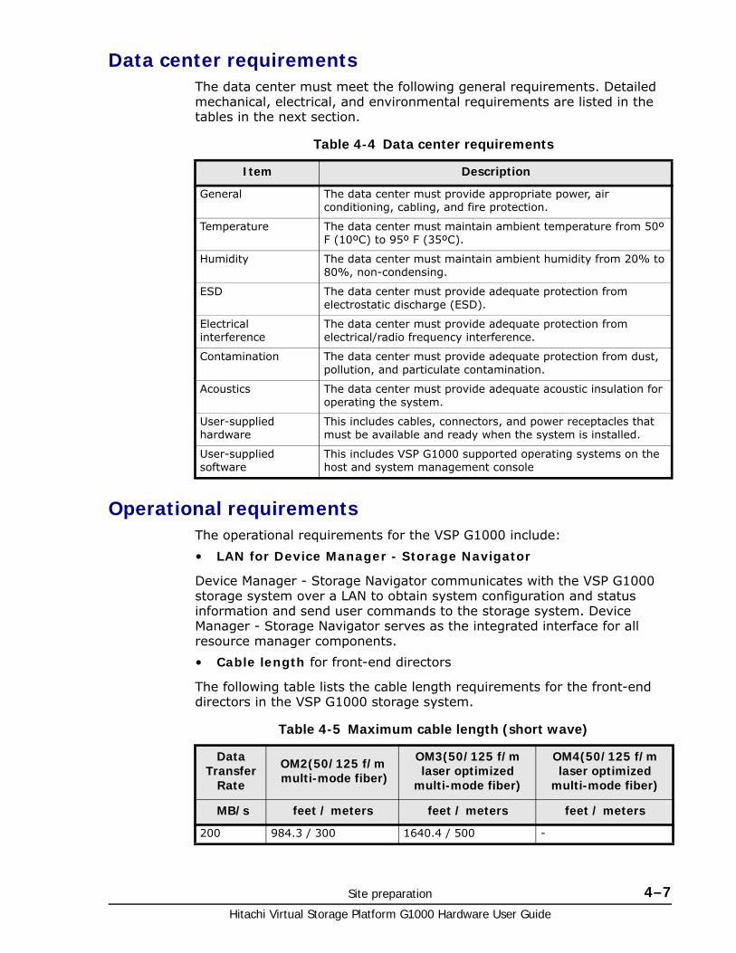
Site preparation 4–7Hitachi Virtual Storage Platform G1000 Hardware User Guide
Data center requirementsThe data center must meet the following general requirements. Detailed mechanical, electrical, and environmental requirements are listed in the tables in the next section.
Table 4-4 Data center requirements
Operational requirementsThe operational requirements for the VSP G1000 include:
• LAN for Device Manager - Storage Navigator
Device Manager - Storage Navigator communicates with the VSP G1000 storage system over a LAN to obtain system configuration and status information and send user commands to the storage system. Device Manager - Storage Navigator serves as the integrated interface for all resource manager components.
• Cable length for front-end directors
The following table lists the cable length requirements for the front-end directors in the VSP G1000 storage system.
Table 4-5 Maximum cable length (short wave)
Item Description
General The data center must provide appropriate power, air conditioning, cabling, and fire protection.
Temperature The data center must maintain ambient temperature from 50º F (10ºC) to 95º F (35ºC).
Humidity The data center must maintain ambient humidity from 20% to 80%, non-condensing.
ESD The data center must provide adequate protection from electrostatic discharge (ESD).
Electrical interference
The data center must provide adequate protection from electrical/radio frequency interference.
Contamination The data center must provide adequate protection from dust, pollution, and particulate contamination.
Acoustics The data center must provide adequate acoustic insulation for operating the system.
User-supplied hardware
This includes cables, connectors, and power receptacles that must be available and ready when the system is installed.
User-supplied software
This includes VSP G1000 supported operating systems on the host and system management console
Data Transfer
Rate
OM2(50/125 f/m multi-mode fiber)
OM3(50/125 f/m laser optimized
multi-mode fiber)
OM4(50/125 f/m laser optimized
multi-mode fiber)
MB/s feet / meters feet / meters feet / meters
200 984.3 / 300 1640.4 / 500 -
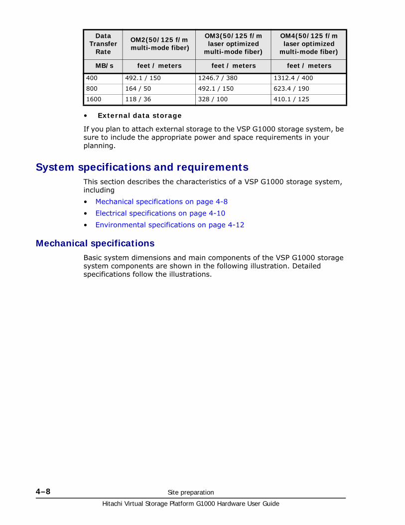
Hitachi Virtual Storage Platform G1000 Hardware User Guide
4–8 Site preparation
• External data storage
If you plan to attach external storage to the VSP G1000 storage system, be sure to include the appropriate power and space requirements in your planning.
System specifications and requirementsThis section describes the characteristics of a VSP G1000 storage system, including
• Mechanical specifications on page 4-8
• Electrical specifications on page 4-10
• Environmental specifications on page 4-12
Mechanical specificationsBasic system dimensions and main components of the VSP G1000 storage system components are shown in the following illustration. Detailed specifications follow the illustrations.
400 492.1 / 150 1246.7 / 380 1312.4 / 400
800 164 / 50 492.1 / 150 623.4 / 190
1600 118 / 36 328 / 100 410.1 / 125
Data Transfer
Rate
OM2(50/125 f/m multi-mode fiber)
OM3(50/125 f/m laser optimized
multi-mode fiber)
OM4(50/125 f/m laser optimized
multi-mode fiber)
MB/s feet / meters feet / meters feet / meters
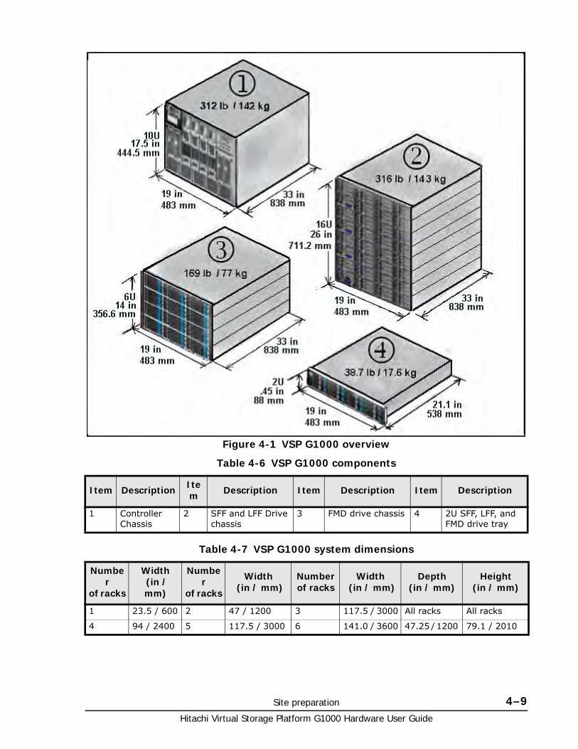
Site preparation 4–9Hitachi Virtual Storage Platform G1000 Hardware User Guide
Table 4-6 VSP G1000 components
Table 4-7 VSP G1000 system dimensions
Figure 4-1 VSP G1000 overview
Item Description Item Description Item Description Item Description
1 Controller Chassis
2 SFF and LFF Drive chassis
3 FMD drive chassis 4 2U SFF, LFF, and FMD drive tray
Number
of racks
Width (in / mm)
Number
of racks
Width (in / mm)
Numberof racks
Width (in / mm)
Depth(in / mm)
Height(in / mm)
1 23.5 / 600 2 47 / 1200 3 117.5 / 3000 All racks All racks
4 94 / 2400 5 117.5 / 3000 6 141.0 / 3600 47.25 / 1200 79.1 / 2010
Hitachi Virtual Storage Platform G1000 Hardware User Guide
4–10 Site preparation
Electrical specifications
The following table lists the electric power requirements of a typical VSP G1000 storage system. Detailed electrical specifications are located in Specifications on page A-1.
Table 4-8 VSP G1000 electric power requirements1
Grounding
The site and site equipment must meet all of the following three grounding requirements.
• An insulated grounding conductor that is identical in size and insulation material and thickness to the grounded and ungrounded branch-circuit supply conductors. It must be green, with or without yellow stripes, and must be installed as a part of the branch circuit that supplies the unit or system.
• The grounding conductor described above should be connected to earth ground at the service equipment or other acceptable building earth ground. In the case of a high rise steel-frame structure, this can be the steel frame
• The receptacles in the vicinity of the unit or system must include a ground connection. The grounding conductors serving these receptacles must be connected to earth ground at the service equipment or other acceptable building earth ground.
Note: The current and power specifications in the following tables were measured on a VSP G1000 system in a controlled environment. To calculate the power draw, current draw, and heat output of a specific system, see Table 4-11 VSP G1000 component specifications on page 4-13 or (easier) use the Power and Weight calculator at the following URL.
http://www.hds.com/go/weight-and-power-calculator/
Contact technical support if you need assistance using this tool.
Phase Voltage Frequency
AC, single phase
2 wire + ground
200 V -8% min 240 V +6% max
50 ±3 Hz
60 ±2 Hz
AC, three phase delta
See Table 4-9 PDU plugs, circuit breakers, and receptacles on page 4-11 for connections.
208 V
+5/-15%
50/60 Hz
Notes:
1: See Electrical specifications on page A-6 for detailed voltage and power requirements.
2. See Table 4-9 PDU plugs, circuit breakers, and receptacles on page 4-11 for system input power requirements.
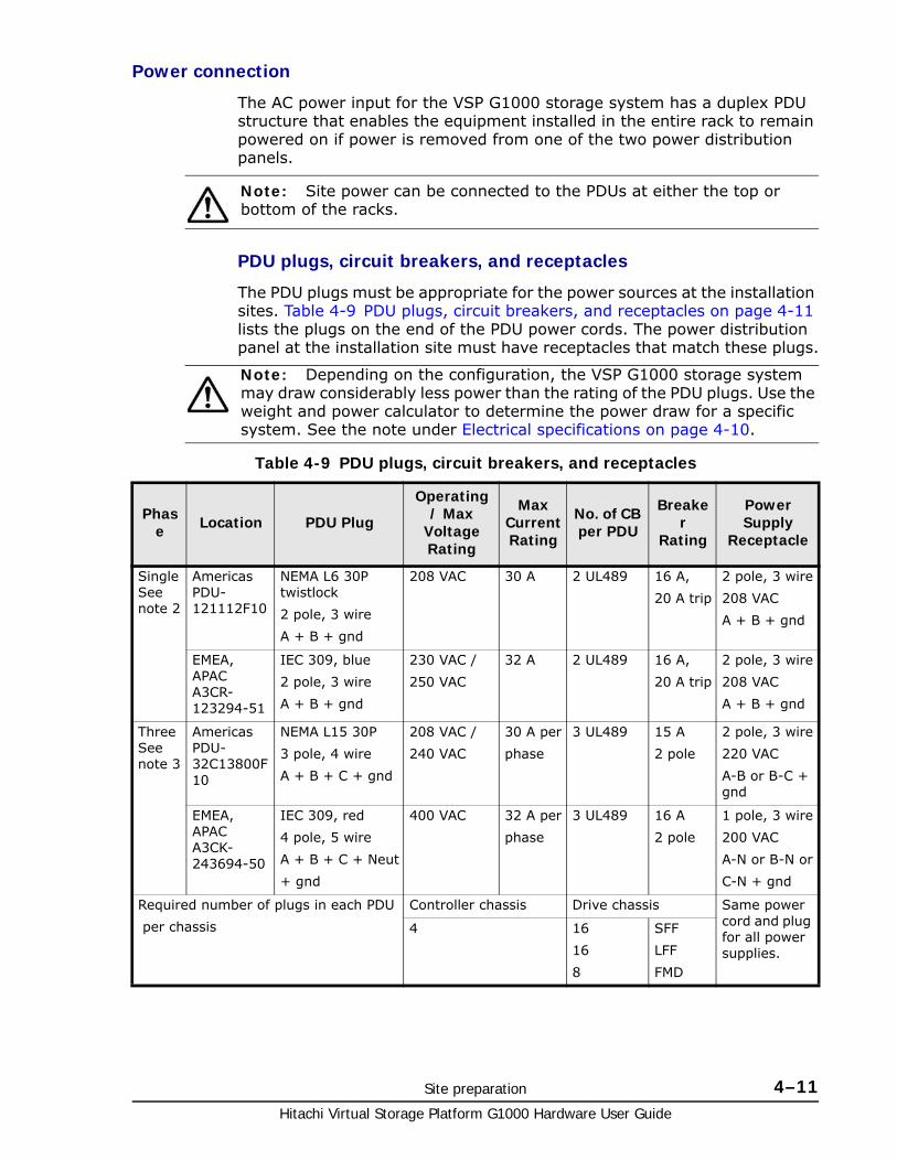
Site preparation 4–11Hitachi Virtual Storage Platform G1000 Hardware User Guide
Power connection
The AC power input for the VSP G1000 storage system has a duplex PDU structure that enables the equipment installed in the entire rack to remain powered on if power is removed from one of the two power distribution panels.
PDU plugs, circuit breakers, and receptacles
The PDU plugs must be appropriate for the power sources at the installation sites. Table 4-9 PDU plugs, circuit breakers, and receptacles on page 4-11 lists the plugs on the end of the PDU power cords. The power distribution panel at the installation site must have receptacles that match these plugs.
Table 4-9 PDU plugs, circuit breakers, and receptacles
Note: Site power can be connected to the PDUs at either the top or bottom of the racks.
Note: Depending on the configuration, the VSP G1000 storage system may draw considerably less power than the rating of the PDU plugs. Use the weight and power calculator to determine the power draw for a specific system. See the note under Electrical specifications on page 4-10.
Phase Location PDU Plug
Operating / Max
Voltage Rating
Max Current Rating
No. of CB per PDU
Breaker
Rating
Power Supply
Receptacle
Single See note 2
Americas PDU-121112F10
NEMA L6 30P twistlock
2 pole, 3 wire
A + B + gnd
208 VAC 30 A 2 UL489 16 A,
20 A trip
2 pole, 3 wire
208 VAC
A + B + gnd
EMEA, APAC A3CR-123294-51
IEC 309, blue
2 pole, 3 wire
A + B + gnd
230 VAC /
250 VAC
32 A 2 UL489 16 A,
20 A trip
2 pole, 3 wire
208 VAC
A + B + gnd
Three See note 3
Americas PDU-32C13800F10
NEMA L15 30P
3 pole, 4 wire
A + B + C + gnd
208 VAC /
240 VAC
30 A per
phase
3 UL489 15 A
2 pole
2 pole, 3 wire
220 VAC
A-B or B-C + gnd
EMEA, APAC A3CK-243694-50
IEC 309, red
4 pole, 5 wire
A + B + C + Neut
+ gnd
400 VAC 32 A per
phase
3 UL489 16 A
2 pole
1 pole, 3 wire
200 VAC
A-N or B-N or
C-N + gnd
Required number of plugs in each PDU
per chassis
Controller chassis Drive chassis Same power cord and plug for all power supplies.
4 16
16
8
SFF
LFF
FMD
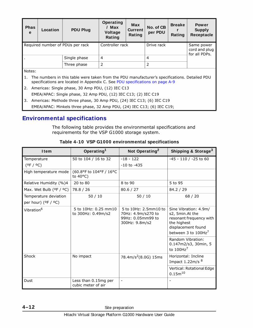
Hitachi Virtual Storage Platform G1000 Hardware User Guide
4–12 Site preparation
Environmental specificationsThe following table provides the environmental specifications and requirements for the VSP G1000 storage system.
Table 4-10 VSP G1000 environmental specifications
Required number of PDUs per rack Controller rack Drive rack Same power cord and plug for all PDPs.
. Single phase 4 4
Three phase 2 2
Notes:
1. The numbers in this table were taken from the PDU manufacturer’s specifications. Detailed PDU specifications are located in Appendix C. See PDU specifications on page A-9
2. Americas: Single phase, 30 Amp PDU, (12) IEC C13
EMEA/APAC: Single phase, 32 Amp PDU, (12) IEC C13; (2) IEC C19
3. Americas: Methode three phase, 30 Amp PDU, (24) IEC C13; (6) IEC C19
EMEA/APAC: Minkels three phase, 32 Amp PDU, (24) IEC C13; (6) IEC C19;
Phase Location PDU Plug
Operating / Max
Voltage Rating
Max Current Rating
No. of CB per PDU
Breaker
Rating
Power Supply
Receptacle
Item Operating1 Not Operating2 Shipping & Storage3
Temperature
(ºF / ºC)
50 to 104 / 16 to 32 -18 - 122
-10 to -435
-45 - 110 / -25 to 60
High temperature mode (60.8°F to 104°F / 16°C to 40°C)
Relative Humidity (%)4 20 to 80 8 to 90 5 to 95
Max. Wet Bulb (ºF / ºC) 78.8 / 26 80.6 / 27 84.2 / 29
Temperature deviation
per hour) (ºF / ºC)
50 / 10 50 / 10 68 / 20
Vibration6 5 to 10Hz: 0.25 mm10 to 300Hz: 0.49m/s2
5 to 10Hz: 2.5mm10 to 70Hz: 4.9m/s270 to 99Hz: 0.05mm99 to 300Hz: 9.8m/s2
Sine Vibration: 4.9m/s2, 5min.At the resonant frequency with the highest displacement found between 3 to 100Hz7
Random Vibration: 0.147m2/s3, 30min, 5 to 100Hz7
Shock No impact 78.4m/s2(8.0G) 15ms Horizontal: Incline Impact 1.22m/s 8
Vertical: Rotational Edge 0.15m10
Dust Less than 0.15mg per cubic meter of air
- -
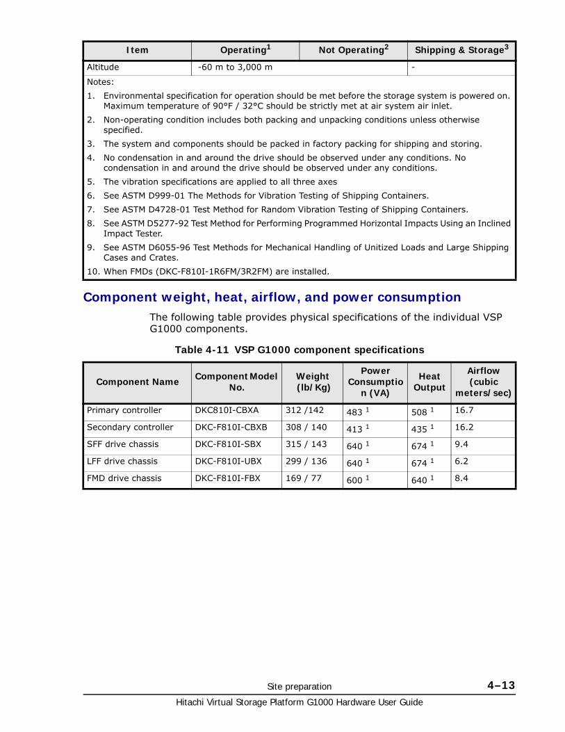
Site preparation 4–13Hitachi Virtual Storage Platform G1000 Hardware User Guide
Component weight, heat, airflow, and power consumptionThe following table provides physical specifications of the individual VSP G1000 components.
Table 4-11 VSP G1000 component specifications
Altitude -60 m to 3,000 m -
Notes:
1. Environmental specification for operation should be met before the storage system is powered on. Maximum temperature of 90°F / 32°C should be strictly met at air system air inlet.
2. Non-operating condition includes both packing and unpacking conditions unless otherwise specified.
3. The system and components should be packed in factory packing for shipping and storing.
4. No condensation in and around the drive should be observed under any conditions. No condensation in and around the drive should be observed under any conditions.
5. The vibration specifications are applied to all three axes
6. See ASTM D999-01 The Methods for Vibration Testing of Shipping Containers.
7. See ASTM D4728-01 Test Method for Random Vibration Testing of Shipping Containers.
8. See ASTM D5277-92 Test Method for Performing Programmed Horizontal Impacts Using an Inclined Impact Tester.
9. See ASTM D6055-96 Test Methods for Mechanical Handling of Unitized Loads and Large Shipping Cases and Crates.
10. When FMDs (DKC-F810I-1R6FM/3R2FM) are installed.
Item Operating1 Not Operating2 Shipping & Storage3
Component Name Component Model No.
Weight (lb/Kg)
Power Consumptio
n (VA)
Heat Output
Airflow (cubic
meters/sec)
Primary controller DKC810I-CBXA 312 /142 483 1 508 1 16.7
Secondary controller DKC-F810I-CBXB 308 / 140 413 1 435 1 16.2
SFF drive chassis DKC-F810I-SBX 315 / 143 640 1 674 1 9.4
LFF drive chassis DKC-F810I-UBX 299 / 136 640 1 674 1 6.2
FMD drive chassis DKC-F810I-FBX 169 / 77 600 1 640 1 8.4
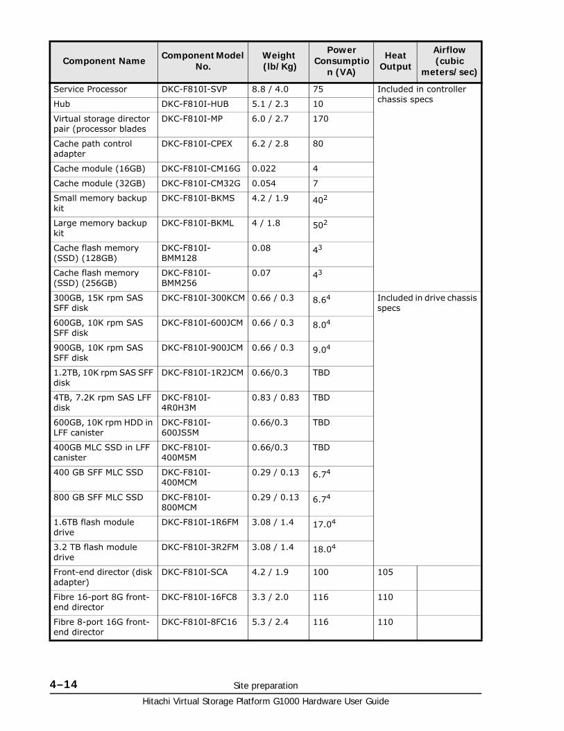
Hitachi Virtual Storage Platform G1000 Hardware User Guide
4–14 Site preparation
Service Processor DKC-F810I-SVP 8.8 / 4.0 75 Included in controller chassis specsHub DKC-F810I-HUB 5.1 / 2.3 10
Virtual storage director pair (processor blades
DKC-F810I-MP 6.0 / 2.7 170
Cache path control adapter
DKC-F810I-CPEX 6.2 / 2.8 80
Cache module (16GB) DKC-F810I-CM16G 0.022 4
Cache module (32GB) DKC-F810I-CM32G 0.054 7
Small memory backup kit
DKC-F810I-BKMS 4.2 / 1.9 402
Large memory backup kit
DKC-F810I-BKML 4 / 1.8 502
Cache flash memory (SSD) (128GB)
DKC-F810I-BMM128
0.08 43
Cache flash memory (SSD) (256GB)
DKC-F810I-BMM256
0.07 43
300GB, 15K rpm SAS SFF disk
DKC-F810I-300KCM 0.66 / 0.3 8.64 Included in drive chassis specs
600GB, 10K rpm SAS SFF disk
DKC-F810I-600JCM 0.66 / 0.3 8.04
900GB, 10K rpm SAS SFF disk
DKC-F810I-900JCM 0.66 / 0.3 9.04
1.2TB, 10K rpm SAS SFF disk
DKC-F810I-1R2JCM 0.66/0.3 TBD
4TB, 7.2K rpm SAS LFF disk
DKC-F810I-4R0H3M
0.83 / 0.83 TBD
600GB, 10K rpm HDD in LFF canister
DKC-F810I-600JS5M
0.66/0.3 TBD
400GB MLC SSD in LFF canister
DKC-F810I-400M5M
0.66/0.3 TBD
400 GB SFF MLC SSD DKC-F810I-400MCM
0.29 / 0.13 6.74
800 GB SFF MLC SSD DKC-F810I-800MCM
0.29 / 0.13 6.74
1.6TB flash module drive
DKC-F810I-1R6FM 3.08 / 1.4 17.04
3.2 TB flash module drive
DKC-F810I-3R2FM 3.08 / 1.4 18.04
Front-end director (disk adapter)
DKC-F810I-SCA 4.2 / 1.9 100 105
Fibre 16-port 8G front-end director
DKC-F810I-16FC8 3.3 / 2.0 116 110
Fibre 8-port 16G front-end director
DKC-F810I-8FC16 5.3 / 2.4 116 110
Component Name Component Model No.
Weight (lb/Kg)
Power Consumptio
n (VA)
Heat Output
Airflow (cubic
meters/sec)
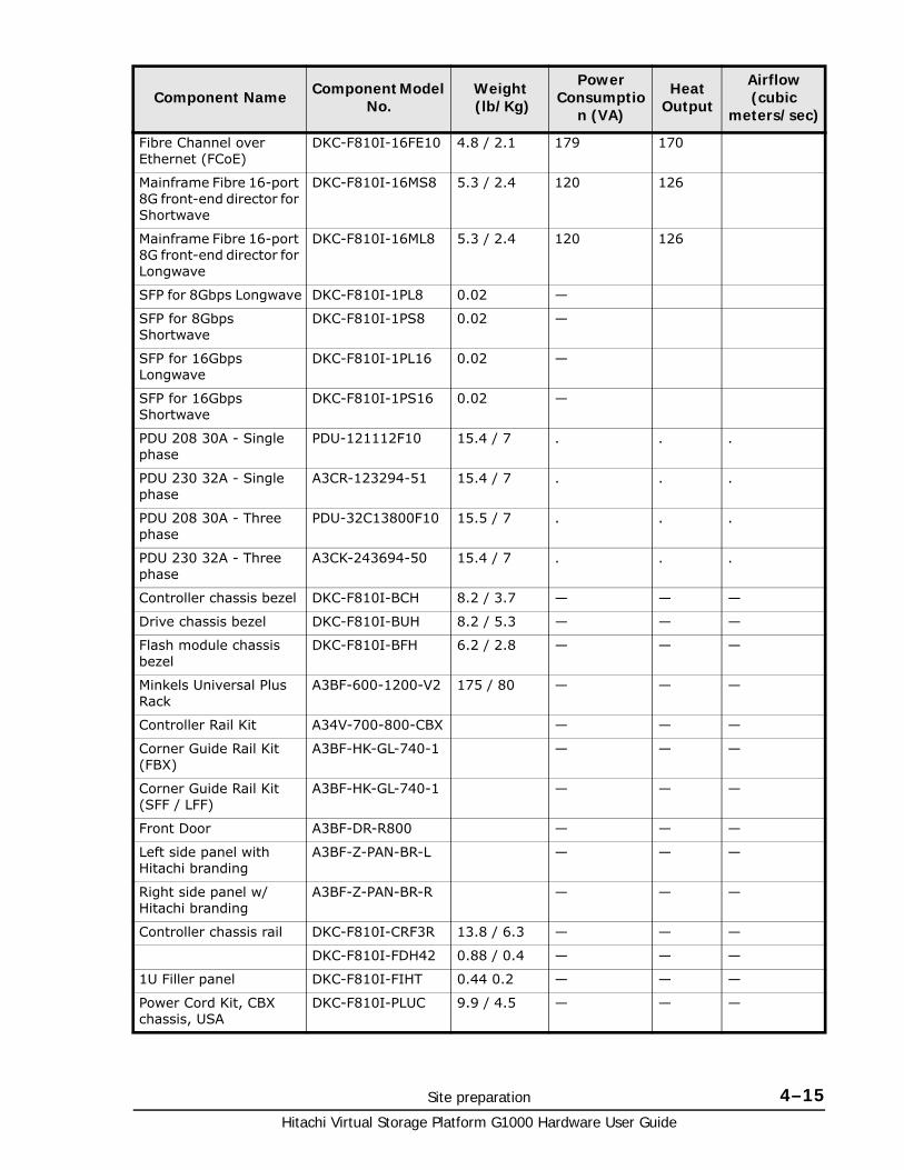
Site preparation 4–15Hitachi Virtual Storage Platform G1000 Hardware User Guide
Fibre Channel over Ethernet (FCoE)
DKC-F810I-16FE10 4.8 / 2.1 179 170
Mainframe Fibre 16-port 8G front-end director for Shortwave
DKC-F810I-16MS8 5.3 / 2.4 120 126
Mainframe Fibre 16-port 8G front-end director for Longwave
DKC-F810I-16ML8 5.3 / 2.4 120 126
SFP for 8Gbps Longwave DKC-F810I-1PL8 0.02 —
SFP for 8Gbps Shortwave
DKC-F810I-1PS8 0.02 —
SFP for 16Gbps Longwave
DKC-F810I-1PL16 0.02 —
SFP for 16Gbps Shortwave
DKC-F810I-1PS16 0.02 —
PDU 208 30A - Single phase
PDU-121112F10 15.4 / 7 . . .
PDU 230 32A - Single phase
A3CR-123294-51 15.4 / 7 . . .
PDU 208 30A - Three phase
PDU-32C13800F10 15.5 / 7 . . .
PDU 230 32A - Three phase
A3CK-243694-50 15.4 / 7 . . .
Controller chassis bezel DKC-F810I-BCH 8.2 / 3.7 — — —
Drive chassis bezel DKC-F810I-BUH 8.2 / 5.3 — — —
Flash module chassis bezel
DKC-F810I-BFH 6.2 / 2.8 — — —
Minkels Universal Plus Rack
A3BF-600-1200-V2 175 / 80 — — —
Controller Rail Kit A34V-700-800-CBX — — —
Corner Guide Rail Kit (FBX)
A3BF-HK-GL-740-1 — — —
Corner Guide Rail Kit (SFF / LFF)
A3BF-HK-GL-740-1 — — —
Front Door A3BF-DR-R800 — — —
Left side panel with Hitachi branding
A3BF-Z-PAN-BR-L — — —
Right side panel w/ Hitachi branding
A3BF-Z-PAN-BR-R — — —
Controller chassis rail DKC-F810I-CRF3R 13.8 / 6.3 — — —
DKC-F810I-FDH42 0.88 / 0.4 — — —
1U Filler panel DKC-F810I-FIHT 0.44 0.2 — — —
Power Cord Kit, CBX chassis, USA
DKC-F810I-PLUC 9.9 / 4.5 — — —
Component Name Component Model No.
Weight (lb/Kg)
Power Consumptio
n (VA)
Heat Output
Airflow (cubic
meters/sec)
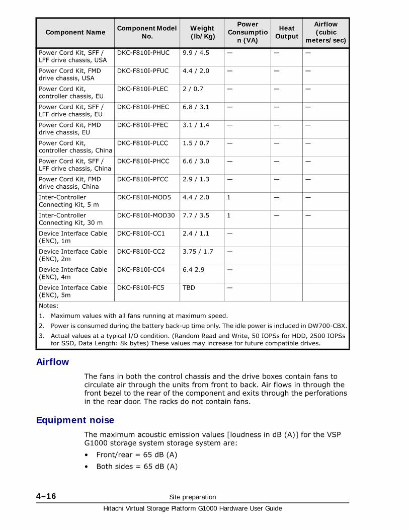
Hitachi Virtual Storage Platform G1000 Hardware User Guide
4–16 Site preparation
AirflowThe fans in both the control chassis and the drive boxes contain fans to circulate air through the units from front to back. Air flows in through the front bezel to the rear of the component and exits through the perforations in the rear door. The racks do not contain fans.
Equipment noiseThe maximum acoustic emission values [loudness in dB (A)] for the VSP G1000 storage system storage system are:
• Front/rear = 65 dB (A)
• Both sides = 65 dB (A)
Power Cord Kit, SFF / LFF drive chassis, USA
DKC-F810I-PHUC 9.9 / 4.5 — — —
Power Cord Kit, FMD drive chassis, USA
DKC-F810I-PFUC 4.4 / 2.0 — — —
Power Cord Kit, controller chassis, EU
DKC-F810I-PLEC 2 / 0.7 — — —
Power Cord Kit, SFF / LFF drive chassis, EU
DKC-F810I-PHEC 6.8 / 3.1 — — —
Power Cord Kit, FMD drive chassis, EU
DKC-F810I-PFEC 3.1 / 1.4 — — —
Power Cord Kit, controller chassis, China
DKC-F810I-PLCC 1.5 / 0.7 — — —
Power Cord Kit, SFF / LFF drive chassis, China
DKC-F810I-PHCC 6.6 / 3.0 — — —
Power Cord Kit, FMD drive chassis, China
DKC-F810I-PFCC 2.9 / 1.3 — — —
Inter-Controller Connecting Kit, 5 m
DKC-F810I-MOD5 4.4 / 2.0 1 — —
Inter-Controller Connecting Kit, 30 m
DKC-F810I-MOD30 7.7 / 3.5 1 — —
Device Interface Cable (ENC), 1m
DKC-F810I-CC1 2.4 / 1.1 —
Device Interface Cable (ENC), 2m
DKC-F810I-CC2 3.75 / 1.7 —
Device Interface Cable (ENC), 4m
DKC-F810I-CC4 6.4 2.9 —
Device Interface Cable (ENC), 5m
DKC-F810I-FC5 TBD —
Notes:
1. Maximum values with all fans running at maximum speed.
2. Power is consumed during the battery back-up time only. The idle power is included in DW700-CBX.
3. Actual values at a typical I/O condition. (Random Read and Write, 50 IOPSs for HDD, 2500 IOPSs for SSD, Data Length: 8k bytes) These values may increase for future compatible drives.
Component Name Component Model No.
Weight (lb/Kg)
Power Consumptio
n (VA)
Heat Output
Airflow (cubic
meters/sec)
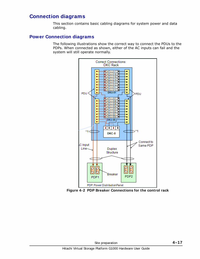
Site preparation 4–17Hitachi Virtual Storage Platform G1000 Hardware User Guide
Connection diagramsThis section contains basic cabling diagrams for system power and data cabling.
Power Connection diagramsThe following illustrations show the correct way to connect the PDUs to the PDPs. When connected as shown, either of the AC inputs can fail and the system will still operate normally.
Figure 4-2 PDP Breaker Connections for the control rack
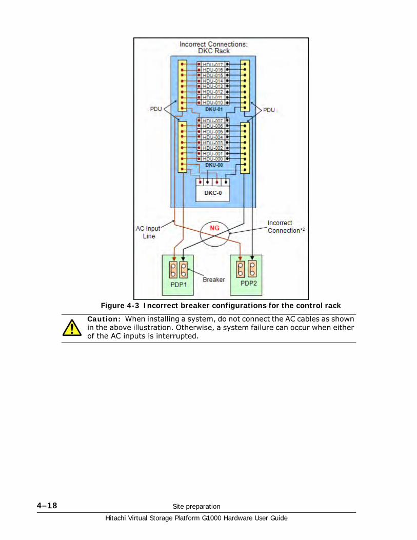
Hitachi Virtual Storage Platform G1000 Hardware User Guide
4–18 Site preparation
Figure 4-3 Incorrect breaker configurations for the control rack
Caution: When installing a system, do not connect the AC cables as shown in the above illustration. Otherwise, a system failure can occur when either of the AC inputs is interrupted.
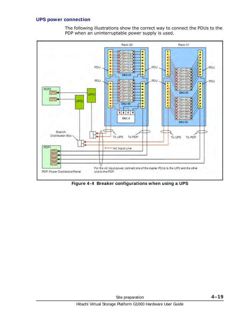
Site preparation 4–19Hitachi Virtual Storage Platform G1000 Hardware User Guide
UPS power connection
The following illustrations show the correct way to connect the PDUs to the PDP when an uninterruptable power supply is used.
Figure 4-4 Breaker configurations when using a UPS
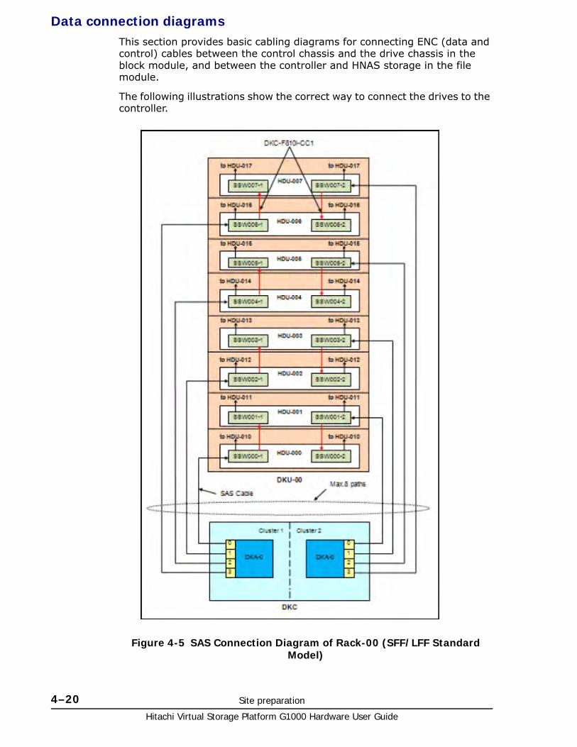
Hitachi Virtual Storage Platform G1000 Hardware User Guide
4–20 Site preparation
Data connection diagramsThis section provides basic cabling diagrams for connecting ENC (data and control) cables between the control chassis and the drive chassis in the block module, and between the controller and HNAS storage in the file module.
The following illustrations show the correct way to connect the drives to the controller.
Figure 4-5 SAS Connection Diagram of Rack-00 (SFF/LFF Standard Model)
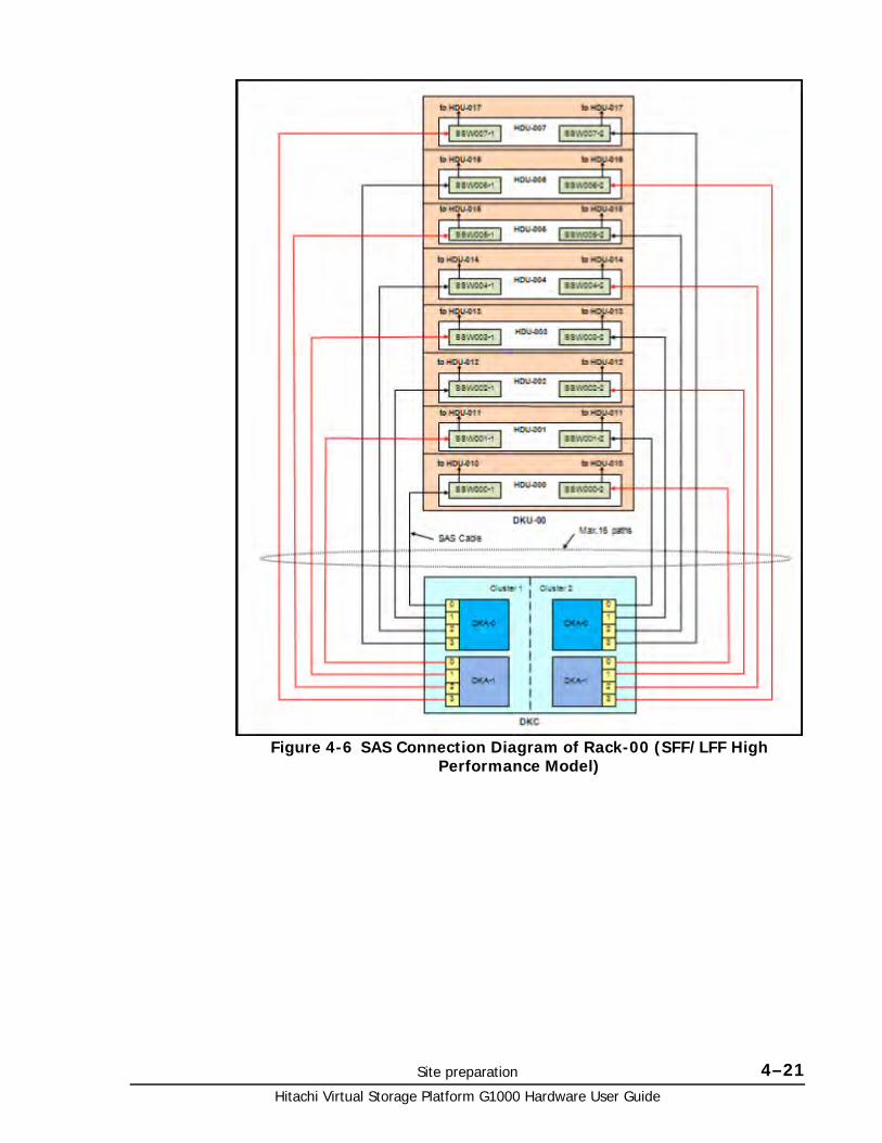
Site preparation 4–21Hitachi Virtual Storage Platform G1000 Hardware User Guide
Figure 4-6 SAS Connection Diagram of Rack-00 (SFF/LFF High Performance Model)
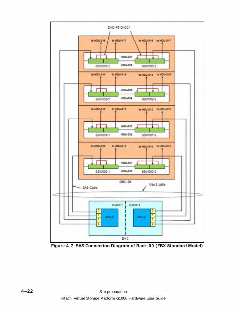
Hitachi Virtual Storage Platform G1000 Hardware User Guide
4–22 Site preparation
Figure 4-7 SAS Connection Diagram of Rack-00 (FBX Standard Model)
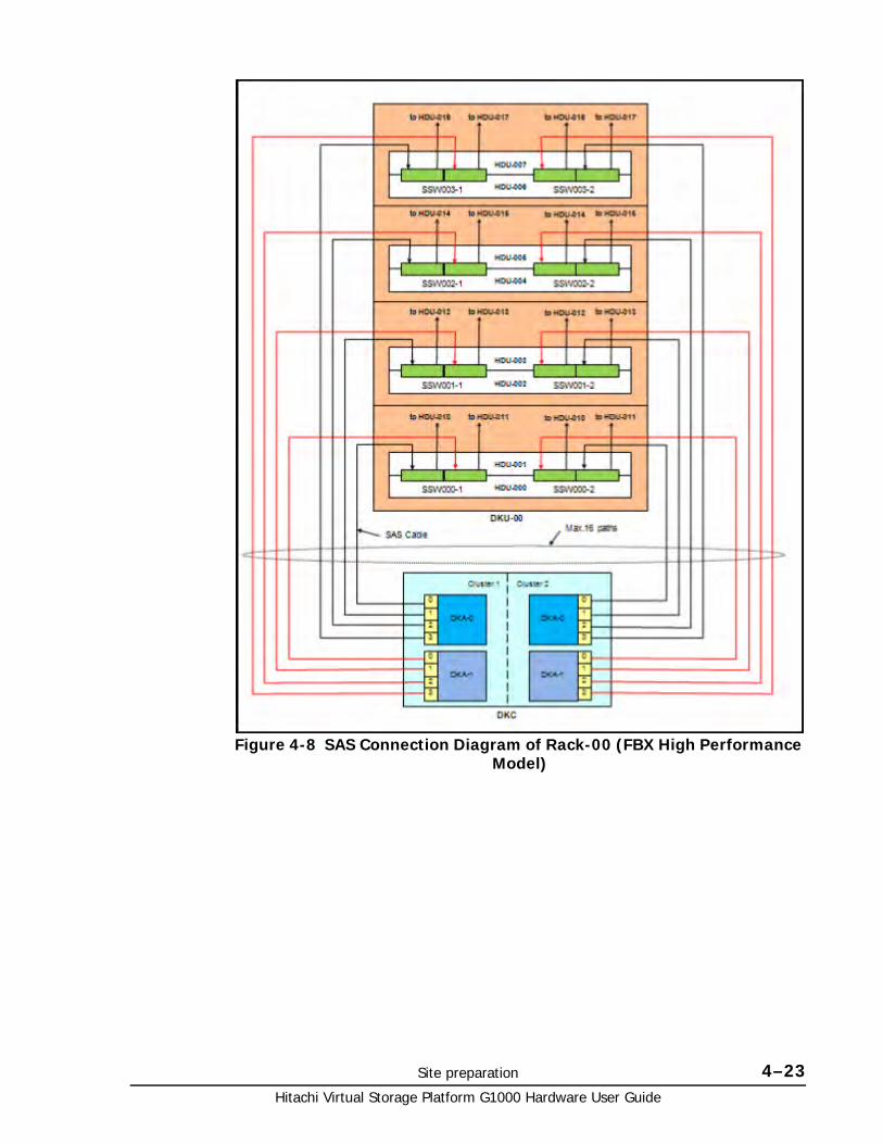
Site preparation 4–23Hitachi Virtual Storage Platform G1000 Hardware User Guide
Figure 4-8 SAS Connection Diagram of Rack-00 (FBX High Performance Model)
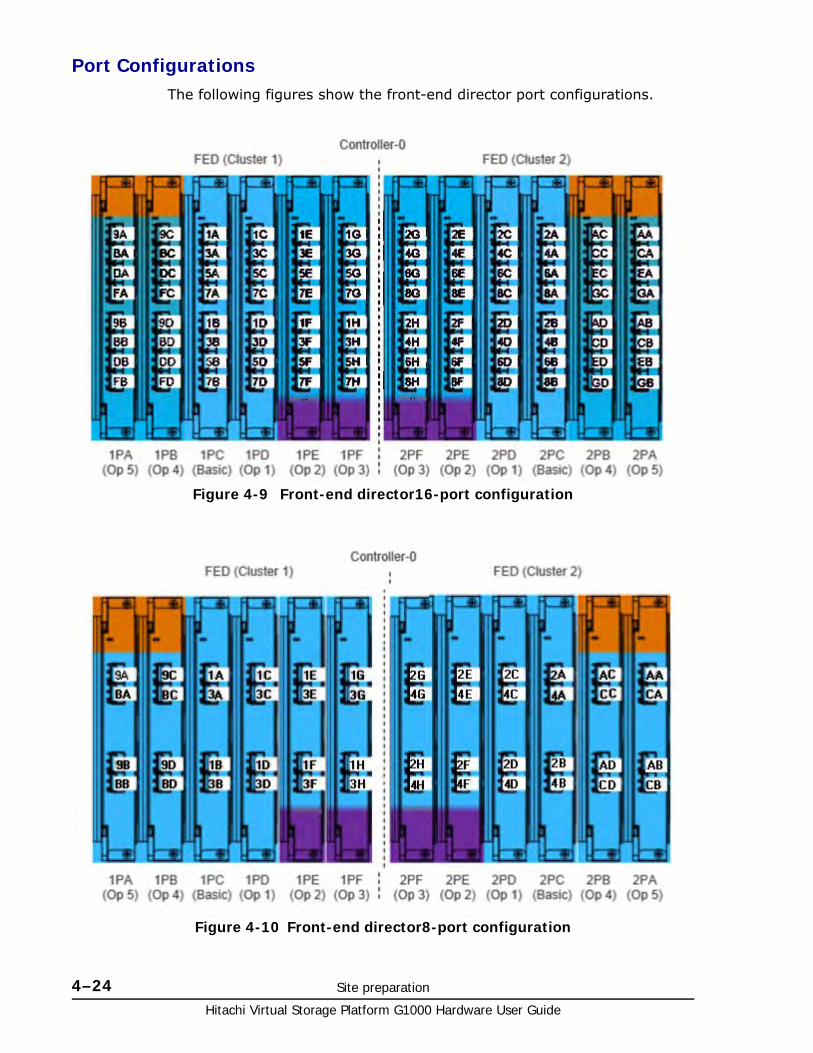
Hitachi Virtual Storage Platform G1000 Hardware User Guide
4–24 Site preparation
Port ConfigurationsThe following figures show the front-end director port configurations.
Figure 4-9 Front-end director16-port configuration
Figure 4-10 Front-end director8-port configuration
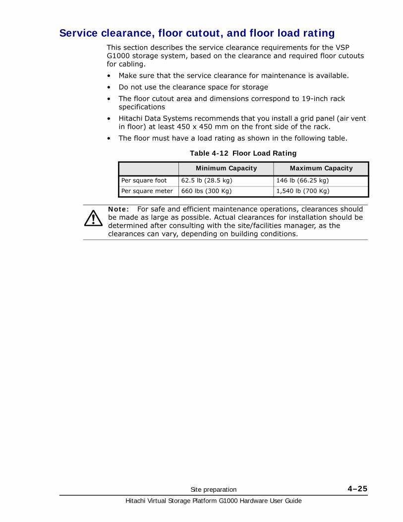
Site preparation 4–25Hitachi Virtual Storage Platform G1000 Hardware User Guide
Service clearance, floor cutout, and floor load ratingThis section describes the service clearance requirements for the VSP G1000 storage system, based on the clearance and required floor cutouts for cabling.
• Make sure that the service clearance for maintenance is available.
• Do not use the clearance space for storage
• The floor cutout area and dimensions correspond to 19-inch rack specifications
• Hitachi Data Systems recommends that you install a grid panel (air vent in floor) at least 450 x 450 mm on the front side of the rack.
• The floor must have a load rating as shown in the following table.
Table 4-12 Floor Load Rating
Minimum Capacity Maximum Capacity
Per square foot 62.5 lb (28.5 kg) 146 lb (66.25 kg)
Per square meter 660 lbs (300 Kg) 1,540 lb (700 Kg)
Note: For safe and efficient maintenance operations, clearances should be made as large as possible. Actual clearances for installation should be determined after consulting with the site/facilities manager, as the clearances can vary, depending on building conditions.
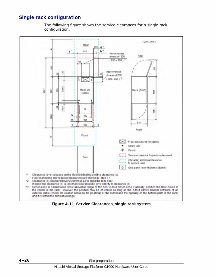
Hitachi Virtual Storage Platform G1000 Hardware User Guide
4–26 Site preparation
Single rack configurationThe following figure shows the service clearances for a single rack configuration.
Figure 4-11 Service Clearances, single rack system

Site preparation 4–27Hitachi Virtual Storage Platform G1000 Hardware User Guide
Table 4-13 Floor load rating and required clearances for single rack configuration
Floor Load Rating
(kg/m2)
Required Clearance (a+b) m
c= -0.3 c=0 c=0.2 c=0.4 c=0.6 c=0.8 c=1.0 c=1.4
Over 700 0 0 0 0 0 0 0 0
600 0.1 0 0 0 0 0 0 0
500 0.3 0.2 0.1 0.1 0 0 0 0
450 0.4 0.3 0.3 0.2 0.1 0.1 0.1 0
400 0.6 0.5 0.4 0.3 0.3 0.2 0.2 0.1
350 0.9 0.7 0.6 0.6 0.5 0.4 0.4 0.3
300 1.4 1.1 1.0 0.9 0.8 0.7 0.6 0.5
Notes;
1. Actual clearances for installation should be determined after consulting with the construction specialist responsible for installations in the building. Clearances can vary depending on the size/layout of the system and building conditions.
2. When various configurations of storage systems are arranged in a row, clearance values based on the largest storage system configuration should be used.
3. For easier maintenance operations, make clearance (c) as large as possible.
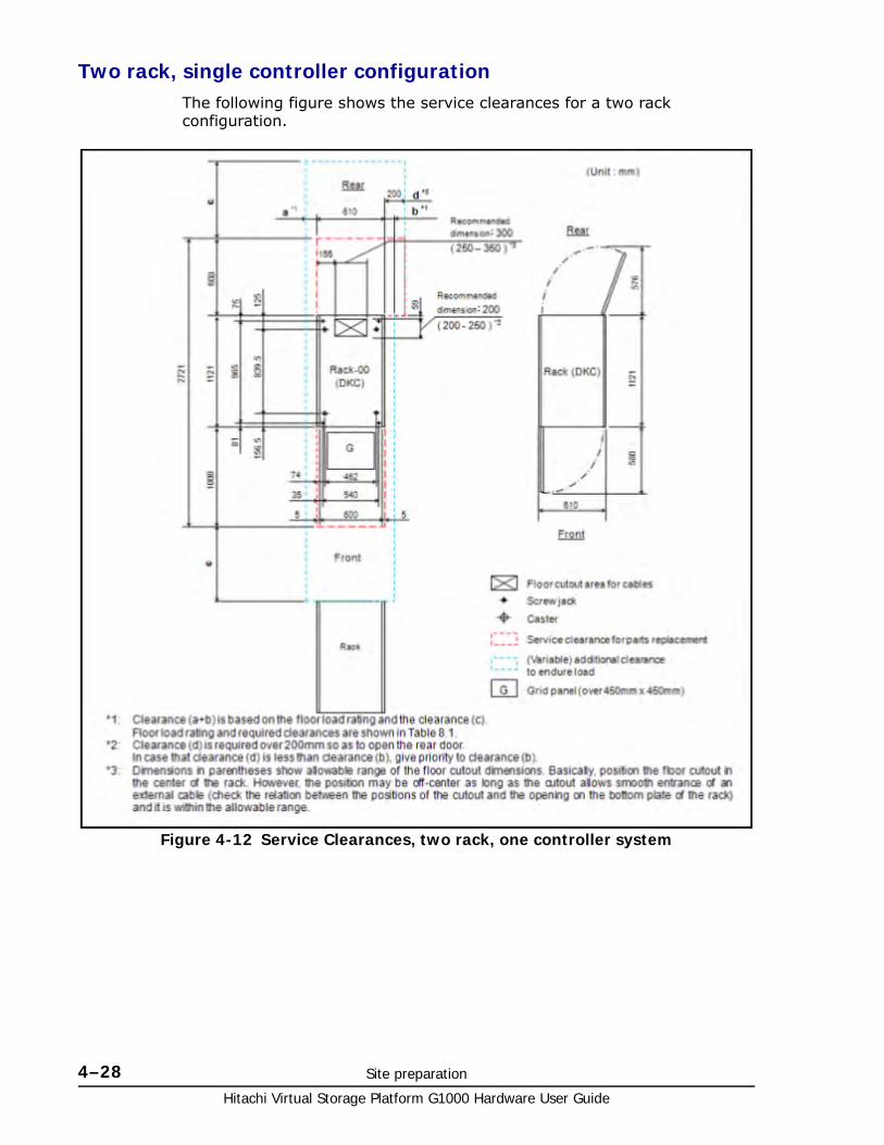
Hitachi Virtual Storage Platform G1000 Hardware User Guide
4–28 Site preparation
Two rack, single controller configurationThe following figure shows the service clearances for a two rack configuration.
Figure 4-12 Service Clearances, two rack, one controller system

Site preparation 4–29Hitachi Virtual Storage Platform G1000 Hardware User Guide
Table 4-14 Floor load rating and required clearances for single rack configuration
Floor Load Rating
(kg/m2)
Required Clearance (a+b) m
c= -0.3 c=0 c=0.2 c=0.4 c=0.6 c=0.8 c=1.0 c=1.4
Over 700 0 0 0 0 0 0 0 0
600 0.1 0 0 0 0 0 0 0
500 0.4 0.2 0.1 0 0 0 0 0
450 0.6 0.4 0.3 0.2 0.1 0 0 0
400 1.0 0.7 0.6 0.5 0.4 0.3 0.2 0
350 1.5 1.2 1.0 0.8 0.7 0.6 0.5 0.3
300 2.2 1.8 1.6 1.4 1/3 1.1 1.0 0.8
Notes;
1. Actual clearances for installation should be determined after consulting with the construction specialist responsible for installations in the building. Clearances can vary depending on the size/layout of the system and building conditions.
2. When various configurations of storage systems are arranged in a row, clearance values based on the largest storage system configuration should be used.
3. For easier maintenance operations, make clearance (c) as large as possible.
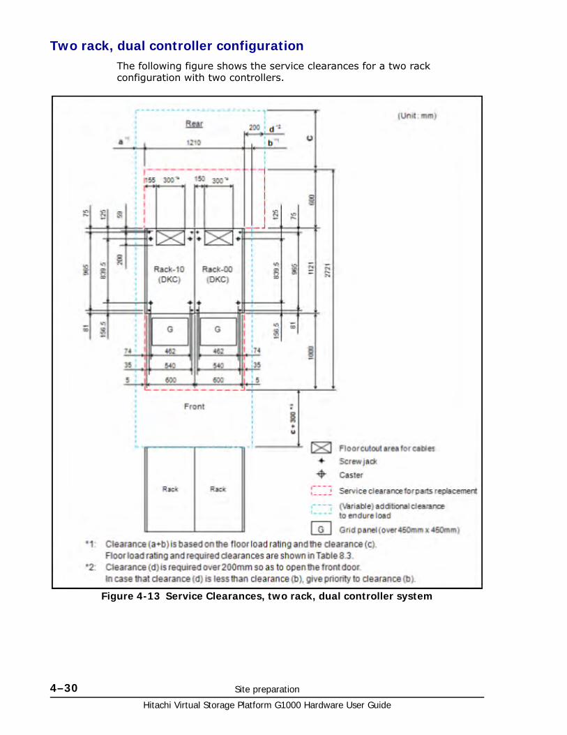
Hitachi Virtual Storage Platform G1000 Hardware User Guide
4–30 Site preparation
Two rack, dual controller configurationThe following figure shows the service clearances for a two rack configuration with two controllers.
Figure 4-13 Service Clearances, two rack, dual controller system

Site preparation 4–31Hitachi Virtual Storage Platform G1000 Hardware User Guide
Table 4-15 Floor load rating and required clearances for single rack configuration
Floor Load Rating
(kg/m2)
Required Clearance (a+b) m
c= -0.3 c=0 c=0.2 c=0.4 c=0.6 c=0.8 c=1.0 c=1.4
Over 700 0 0 0 0 0 0 0 0
600 0.2 0 0 0 0 0 0 0
500 0.6 0.4 0.2 0.1 0 0 0 0
450 0.8 0.6 0.5 0.4 0.1 0.2 0.1 0
400 1.2 0.9 0.8 0.6 0.4 0.4 0.3 0.2
350 1.8 1.4 1.3 1.1 0.7 0.8 0.7 0.5
300 2.6 2.2 1.9 1.7 1/3 1.4 1.2 1.0
Notes;
1. Actual clearances for installation should be determined after consulting with the construction specialist responsible for installations in the building. Clearances can vary depending on the size/layout of the system and building conditions.
2. When various configurations of storage systems are arranged in a row, clearance values based on the largest storage system configuration should be used.
3. For easier maintenance operations, make clearance (c) as large as possible.
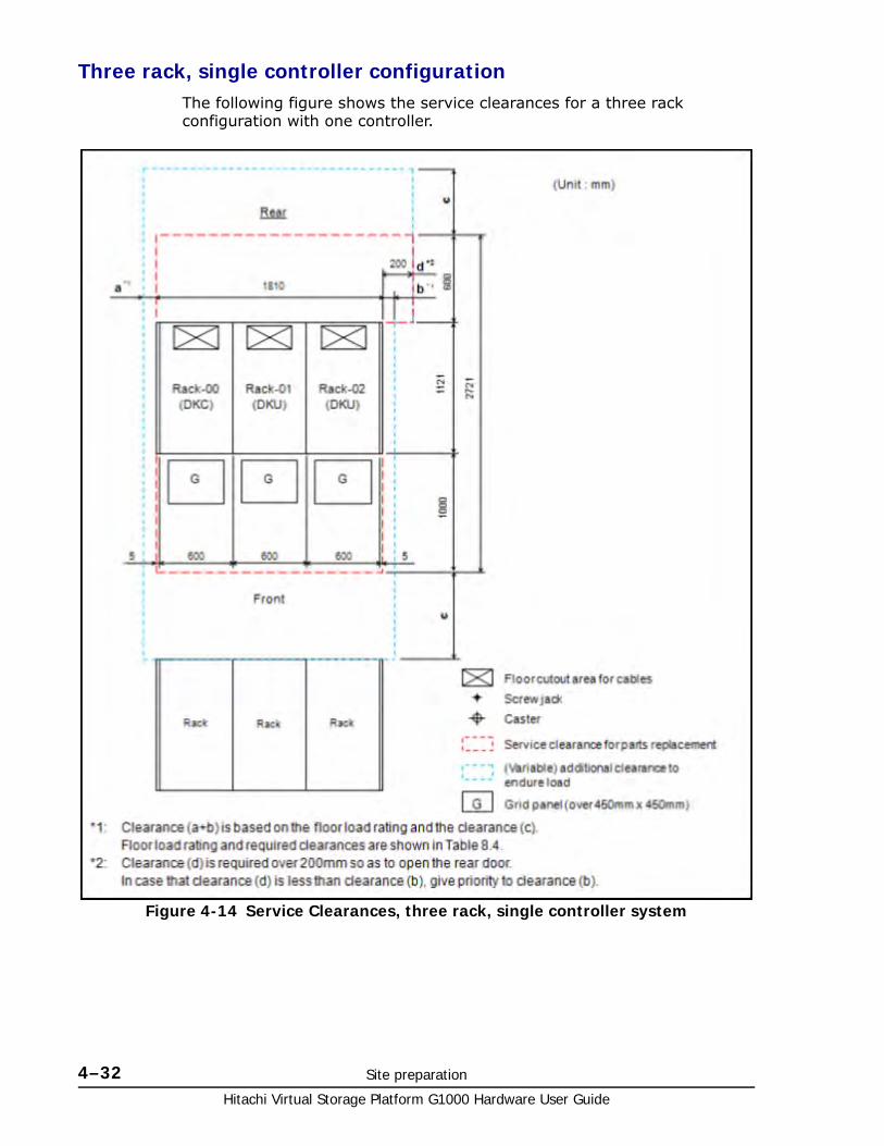
Hitachi Virtual Storage Platform G1000 Hardware User Guide
4–32 Site preparation
Three rack, single controller configurationThe following figure shows the service clearances for a three rack configuration with one controller.
Figure 4-14 Service Clearances, three rack, single controller system
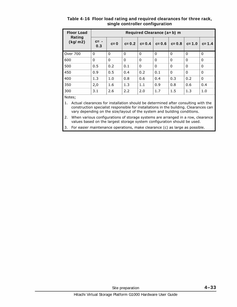
Site preparation 4–33Hitachi Virtual Storage Platform G1000 Hardware User Guide
Table 4-16 Floor load rating and required clearances for three rack, single controller configuration
Floor Load Rating
(kg/m2)
Required Clearance (a+b) m
c= -0.3 c=0 c=0.2 c=0.4 c=0.6 c=0.8 c=1.0 c=1.4
Over 700 0 0 0 0 0 0 0 0
600 0 0 0 0 0 0 0 0
500 0.5 0.2 0.1 0 0 0 0 0
450 0.9 0.5 0.4 0.2 0.1 0 0 0
400 1.3 1.0 0.8 0.6 0.4 0.3 0.2 0
350 2,0 1.6 1.3 1.1 0.9 0.8 0.6 0.4
300 3.1 2.6 2.2 2.0 1.7 1.5 1.3 1.0
Notes;
1. Actual clearances for installation should be determined after consulting with the construction specialist responsible for installations in the building. Clearances can vary depending on the size/layout of the system and building conditions.
2. When various configurations of storage systems are arranged in a row, clearance values based on the largest storage system configuration should be used.
3. For easier maintenance operations, make clearance (c) as large as possible.
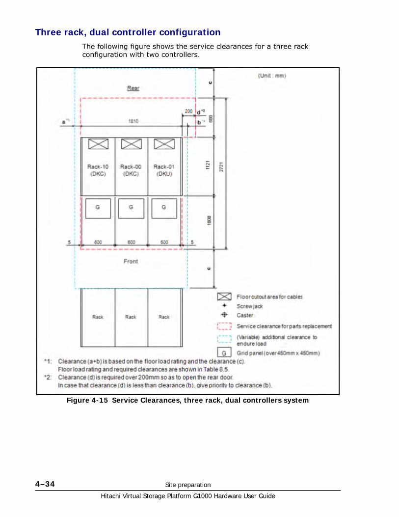
Hitachi Virtual Storage Platform G1000 Hardware User Guide
4–34 Site preparation
Three rack, dual controller configurationThe following figure shows the service clearances for a three rack configuration with two controllers.
Figure 4-15 Service Clearances, three rack, dual controllers system
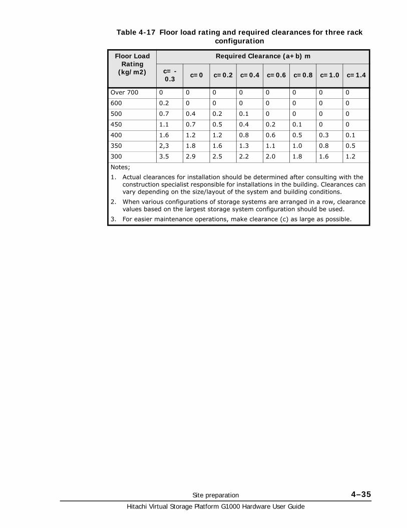
Site preparation 4–35Hitachi Virtual Storage Platform G1000 Hardware User Guide
Table 4-17 Floor load rating and required clearances for three rack configuration
Floor Load Rating
(kg/m2)
Required Clearance (a+b) m
c= -0.3 c=0 c=0.2 c=0.4 c=0.6 c=0.8 c=1.0 c=1.4
Over 700 0 0 0 0 0 0 0 0
600 0.2 0 0 0 0 0 0 0
500 0.7 0.4 0.2 0.1 0 0 0 0
450 1.1 0.7 0.5 0.4 0.2 0.1 0 0
400 1.6 1.2 1.2 0.8 0.6 0.5 0.3 0.1
350 2,3 1.8 1.6 1.3 1.1 1.0 0.8 0.5
300 3.5 2.9 2.5 2.2 2.0 1.8 1.6 1.2
Notes;
1. Actual clearances for installation should be determined after consulting with the construction specialist responsible for installations in the building. Clearances can vary depending on the size/layout of the system and building conditions.
2. When various configurations of storage systems are arranged in a row, clearance values based on the largest storage system configuration should be used.
3. For easier maintenance operations, make clearance (c) as large as possible.
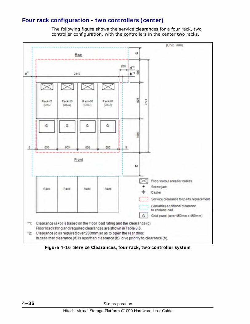
Hitachi Virtual Storage Platform G1000 Hardware User Guide
4–36 Site preparation
Four rack configuration - two controllers (center)The following figure shows the service clearances for a four rack, two controller configuration, with the controllers in the center two racks.
Figure 4-16 Service Clearances, four rack, two controller system

Site preparation 4–37Hitachi Virtual Storage Platform G1000 Hardware User Guide
Table 4-18 Floor load rating and required clearances for a four rack, two controller system
Floor Load Rating
(kg/m2)
Required Clearance (a+b) m
c= -0.3 c=0 c=0.2 c=0.4 c=0.6 c=0.8 c=1.0 c=1.4
Over 700 0 0 0 0 0 0 0 0
600 0.1 0 0 0 0 0 0 0
500 0.8 0.4 0.2 0 0 0 0 0
450 1.3 0.8 0.6 0.4 0.2 0.1 0 0
400 1.9 1.4 1.1 0.9 0.7 0.5 0.3 0.1
350 2,9 2.3 1.9 1.6 1.4 1.2 0.9 0.6
300 4.4 3.6 3.2 2.8 2.5 2.2 1.9 1.5
Notes;
1. Actual clearances for installation should be determined after consulting with the construction specialist responsible for installations in the building. Clearances can vary depending on the size/layout of the system and building conditions.
2. When various configurations of storage systems are arranged in a row, clearance values based on the largest storage system configuration should be used.
3. For easier maintenance operations, make clearance (c) as large as possible.
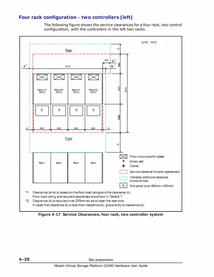
Hitachi Virtual Storage Platform G1000 Hardware User Guide
4–38 Site preparation
Four rack configuration - two controllers (left)The following figure shows the service clearances for a four rack, two control configuration, with the controllers in the left two racks.
Figure 4-17 Service Clearances, four rack, two controller system

Site preparation 4–39Hitachi Virtual Storage Platform G1000 Hardware User Guide
Table 4-19 Floor load rating and required clearances for a four rack, two controller system
Floor Load Rating
(kg/m2)
Required Clearance (a+b) m
c= -0.3 c=0 c=0.2 c=0.4 c=0.6 c=0.8 c=1.0 c=1.4
Over 700 0 0 0 0 0 0 0 0
600 0.2 0 0 0 0 0 0 0
500 0.7 0.4 0.2 0.1 0 0 0 0
450 1.1 0.7 0.5 0.4 0.2 0.1 0 0
400 1.6 1.2 1.2 0.8 0.6 0.5 0.3 0.1
350 2,3 1.8 1.6 1.3 1.1 1.0 0.8 0.5
300 3.5 2.9 2.5 2.2 2.0 1.8 1.6 1.2
Notes;
1. Actual clearances for installation should be determined after consulting with the construction specialist responsible for installations in the building. Clearances can vary depending on the size/layout of the system and building conditions.
2. When various configurations of storage systems are arranged in a row, clearance values based on the largest storage system configuration should be used.
3. For easier maintenance operations, make clearance (c) as large as possible.
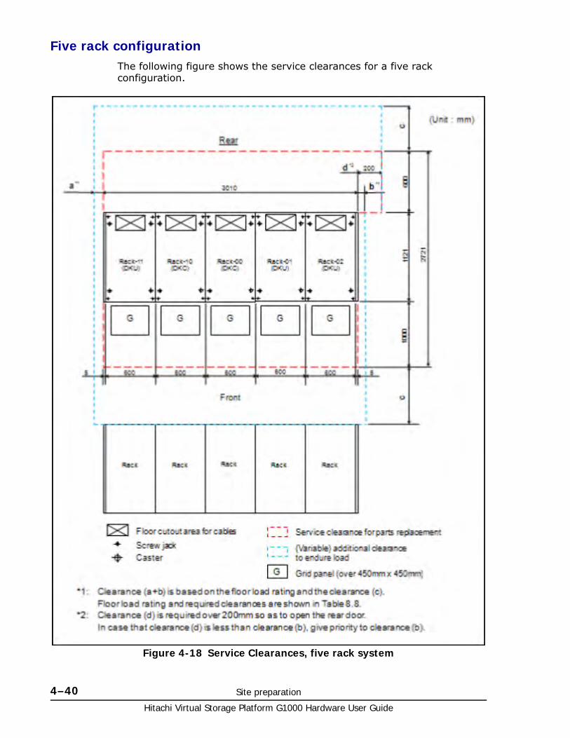
Hitachi Virtual Storage Platform G1000 Hardware User Guide
4–40 Site preparation
Five rack configurationThe following figure shows the service clearances for a five rack configuration.
Figure 4-18 Service Clearances, five rack system
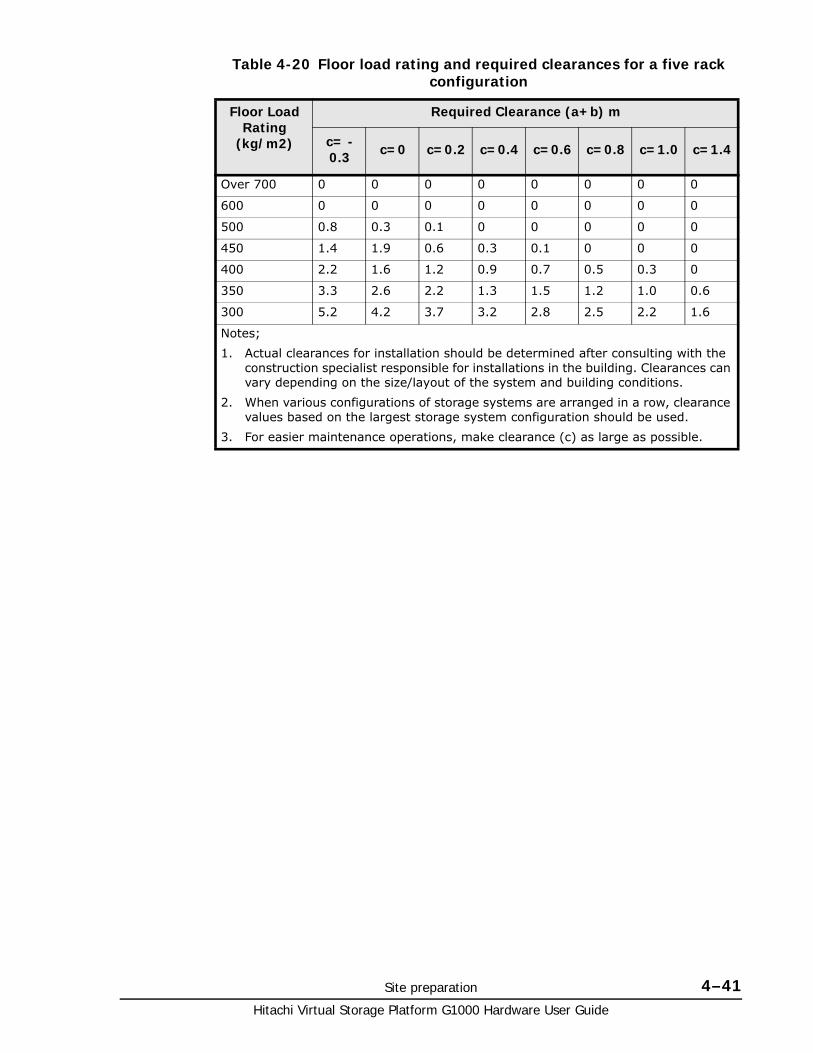
Site preparation 4–41Hitachi Virtual Storage Platform G1000 Hardware User Guide
Table 4-20 Floor load rating and required clearances for a five rack configuration
Floor Load Rating
(kg/m2)
Required Clearance (a+b) m
c= -0.3 c=0 c=0.2 c=0.4 c=0.6 c=0.8 c=1.0 c=1.4
Over 700 0 0 0 0 0 0 0 0
600 0 0 0 0 0 0 0 0
500 0.8 0.3 0.1 0 0 0 0 0
450 1.4 1.9 0.6 0.3 0.1 0 0 0
400 2.2 1.6 1.2 0.9 0.7 0.5 0.3 0
350 3.3 2.6 2.2 1.3 1.5 1.2 1.0 0.6
300 5.2 4.2 3.7 3.2 2.8 2.5 2.2 1.6
Notes;
1. Actual clearances for installation should be determined after consulting with the construction specialist responsible for installations in the building. Clearances can vary depending on the size/layout of the system and building conditions.
2. When various configurations of storage systems are arranged in a row, clearance values based on the largest storage system configuration should be used.
3. For easier maintenance operations, make clearance (c) as large as possible.
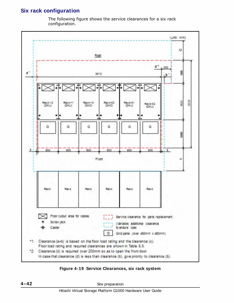
Hitachi Virtual Storage Platform G1000 Hardware User Guide
4–42 Site preparation
Six rack configurationThe following figure shows the service clearances for a six rack configuration.
Figure 4-19 Service Clearances, six rack system

Site preparation 4–43Hitachi Virtual Storage Platform G1000 Hardware User Guide
Table 4-21 Floor load rating and required clearances for six rack configuration
Floor Load Rating
(kg/m2)
Required Clearance (a+b) m
c= -0.3 c=0 c=0.2 c=0.4 c=0.6 c=0.8 c=1.0 c=1.4
Over 700 0 0 0 0 0 0 0 0
600 0 0 0 0 0 0 0 0
500 1.0 0.4 0.1 0 0 0 0 0
450 1.7 1.1 0.7 0.4 0.2 0 0 0
400 2.6 1.9 1.5 1.2 0.9 0.6 0.3 0
350 4.0 3.1 2.6 2.2 1.8 1.5 1.2 0.7
300 6.2 5.1 4.4 3.9 3.4 2.0 2.6 2.0
Notes;
1. Actual clearances for installation should be determined after consulting with the construction specialist responsible for installations in the building. Clearances can vary depending on the size/layout of the system and building conditions.
2. When various configurations of storage systems are arranged in a row, clearance values based on the largest storage system configuration should be used.
3. For easier maintenance operations, make clearance (c) as large as possible.

Hitachi Virtual Storage Platform G1000 Hardware User Guide
4–44 Site preparation

5
Power On/Off procedures 5–1Hitachi Virtual Storage Platform G1000 Hardware User Guide
Power On/Off procedures
This chapter describes the prerequisites and procedures to turn the Hitachi Virtual Storage Platform G1000 power on and off. It also describes the procedures to follow in case of a power failure.
□ Safety and environmental information
□ Power control panel
□ System idle mode
□ Normal power On/Off procedures
□ Emergency power off/on procedures
□ Battery backup operations
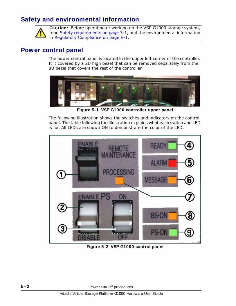
Hitachi Virtual Storage Platform G1000 Hardware User Guide
5–2 Power On/Off procedures
Safety and environmental information
Power control panelThe power control panel is located in the upper left corner of the controller. It it covered by a 2U high bezel that can be removed separately from the 8U bezel that covers the rest of the controller.
The following illustration shows the switches and indicators on the control panel. The table following the illustration explains what each switch and LED is for. All LEDs are shown ON to demonstrate the color of the LED.
Caution: Before operating or working on the VSP G1000 storage system, read Safety requirements on page 3-1, and the environmental information in Regulatory Compliance on page E-1.
Figure 5-1 VSP G1000 controller upper panel
Figure 5-2 VSP G1000 control panel
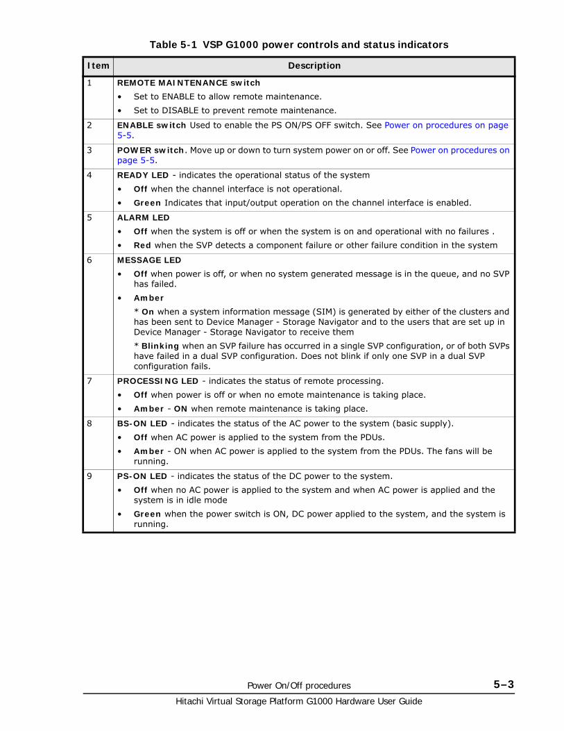
Power On/Off procedures 5–3Hitachi Virtual Storage Platform G1000 Hardware User Guide
Table 5-1 VSP G1000 power controls and status indicators
Item Description
1 REMOTE MAINTENANCE switch
• Set to ENABLE to allow remote maintenance.
• Set to DISABLE to prevent remote maintenance.
2 ENABLE switch Used to enable the PS ON/PS OFF switch. See Power on procedures on page 5-5.
3 POWER switch. Move up or down to turn system power on or off. See Power on procedures on page 5-5.
4 READY LED - indicates the operational status of the system
• Off when the channel interface is not operational.
• Green Indicates that input/output operation on the channel interface is enabled.
5 ALARM LED
• Off when the system is off or when the system is on and operational with no failures .
• Red when the SVP detects a component failure or other failure condition in the system
6 MESSAGE LED
• Off when power is off, or when no system generated message is in the queue, and no SVP has failed.
• Amber
* On when a system information message (SIM) is generated by either of the clusters and has been sent to Device Manager - Storage Navigator and to the users that are set up in Device Manager - Storage Navigator to receive them
* Blinking when an SVP failure has occurred in a single SVP configuration, or of both SVPs have failed in a dual SVP configuration. Does not blink if only one SVP in a dual SVP configuration fails.
7 PROCESSING LED - indicates the status of remote processing.
• Off when power is off or when no emote maintenance is taking place.
• Amber - ON when remote maintenance is taking place.
8 BS-ON LED - indicates the status of the AC power to the system (basic supply).
• Off when AC power is applied to the system from the PDUs.
• Amber - ON when AC power is applied to the system from the PDUs. The fans will be running.
9 PS-ON LED - indicates the status of the DC power to the system.
• Off when no AC power is applied to the system and when AC power is applied and the system is in idle mode
• Green when the power switch is ON, DC power applied to the system, and the system is running.
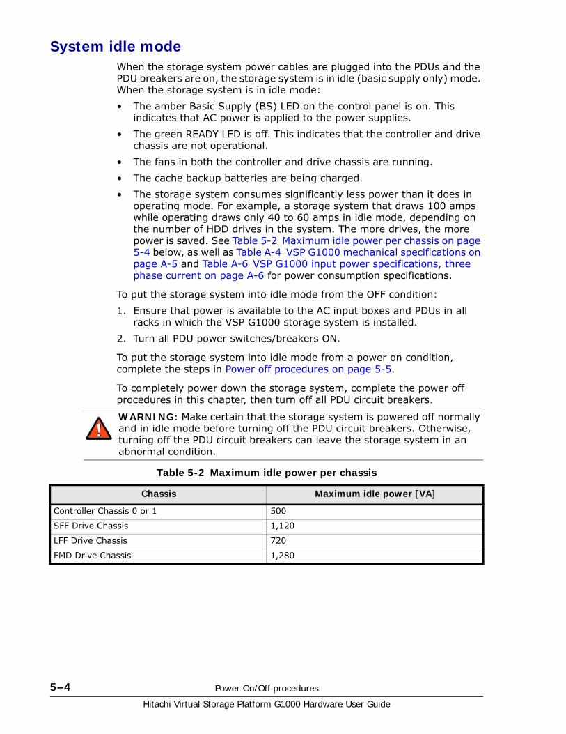
Hitachi Virtual Storage Platform G1000 Hardware User Guide
5–4 Power On/Off procedures
System idle modeWhen the storage system power cables are plugged into the PDUs and the PDU breakers are on, the storage system is in idle (basic supply only) mode. When the storage system is in idle mode:
• The amber Basic Supply (BS) LED on the control panel is on. This indicates that AC power is applied to the power supplies.
• The green READY LED is off. This indicates that the controller and drive chassis are not operational.
• The fans in both the controller and drive chassis are running.
• The cache backup batteries are being charged.
• The storage system consumes significantly less power than it does in operating mode. For example, a storage system that draws 100 amps while operating draws only 40 to 60 amps in idle mode, depending on the number of HDD drives in the system. The more drives, the more power is saved. See Table 5-2 Maximum idle power per chassis on page 5-4 below, as well as Table A-4 VSP G1000 mechanical specifications on page A-5 and Table A-6 VSP G1000 input power specifications, three phase current on page A-6 for power consumption specifications.
To put the storage system into idle mode from the OFF condition:
1. Ensure that power is available to the AC input boxes and PDUs in all racks in which the VSP G1000 storage system is installed.
2. Turn all PDU power switches/breakers ON.
To put the storage system into idle mode from a power on condition, complete the steps in Power off procedures on page 5-5.
To completely power down the storage system, complete the power off procedures in this chapter, then turn off all PDU circuit breakers.
Table 5-2 Maximum idle power per chassis
WARNING: Make certain that the storage system is powered off normally and in idle mode before turning off the PDU circuit breakers. Otherwise, turning off the PDU circuit breakers can leave the storage system in an abnormal condition.
Chassis Maximum idle power [VA]
Controller Chassis 0 or 1 500
SFF Drive Chassis 1,120
LFF Drive Chassis 720
FMD Drive Chassis 1,280
Power On/Off procedures 5–5Hitachi Virtual Storage Platform G1000 Hardware User Guide
Normal power On/Off proceduresThis section provides general information about power on/off procedures for the VSP G1000 storage system. If needed, call technical support for assistance.
Power on proceduresPrerequisites:
• Ensure that the storage system is in idle mode. See System idle mode on page 5-4.
Follow this procedure exactly when turning the storage system on. Refer to the illustration of the control panel in Figure 5-2 VSP G1000 control panel on page 5-2, as needed.
1. On the control panel, check the amber BS LED and make sure it is lit. It indicates that the storage system is in idle mode.
2. In the PS area on the control panel, move the ENABLE switch to the ENABLE position and hold it there. While holding the switch in the ENABLE position, move the PS ON/OFF switch to the ON position. Then release both switches.
3. Wait for the storage system to complete its power-on self-test and boot-up processes. Depending on the storage system configuration, this may take several minutes.
4. When the system self test is complete and all components are operating normally, the green READY LED will light. When the green READY LED is ON, the storage system is ready for use.
Power off proceduresPrerequisites:
• Ensure that all maintenance and software-specific shutdown procedures have been completed. For details, refer to the applicable user manuals.
• Ensure that all I/O activity to the storage system has stopped. You can vary paths offline and shut down the attached hosts.
Note: The control panel includes a safety feature to prevent the storage system power from accidentally being turned on or off. The PS power ON/OFF switch does not work unless the ENABLE switch is moved to and held in the ENABLE position while the power switch is moved to the ON or OFF positions.
Note: The storage system will not go to the READY state until the cache backup batteries are charged to at least 50%. This could take up to 90 minutes if the batteries are completely discharged. The storage system generates a SIM that provides the status of the battery charge. See Cache backup batteries on page 5-8 for information about the batteries.
Note: If the ALARM LED is also on, or if the READY LED is not ON after 20 minutes, contact Technical Support for assistance.

Hitachi Virtual Storage Platform G1000 Hardware User Guide
5–6 Power On/Off procedures
.
Follow this procedure exactly when powering the storage system off.
1. In the PS area on the control panel, move the ENABLE switch to the ENABLED position and hold it there. While holding the switch in the ENABLED position, move the PS ON/OFF switch to the OFF position. Then release both switches.
2. Wait for the storage system to complete its shutdown routines. Depending on the storage system configuration and certain MODE settings, it can take up to 20 minutes for the storage system to copy data from the cache to the cache flash drives and for the disk drives to spin down.
Emergency power off/on proceduresThis section describes the procedures to follow to shut down the system in case of emergency and how to bring the system back up after an emergency shutdown.
Emergency power off procedureThe VSP G1000 storage system does not have an emergency power off switch.
To shut the system down in an emergency, turn off the controllers first, then the drive units, as follows.
1. Open the back doors of both racks that contain control units.a. Turn off the circuit breakers in both lower PDUs in both racks.b. Turn off the circuit breakers in both upper PDUs in both racks with
control units.
2. Open the back doors of all racks that contain only drive units and turn the circuit breakers off in all the PDUs in any order in those racks.
Caution: Except in an emergency, do not turn the PDU breakers off before you turn the system power off. If you do, the system will react as it would in a power failure and use the cache backup batteries to keep the cache alive until data in the cache has been transferred to the cache backup flash memory. Emergency processing drains the batteries and prolongs the next power-on time depending how much charge remains inthe batteries. Fully discharged batteries take 90 minutes to charge.
Note: The control panel includes a safety feature to prevent the storage system power from accidentally being turned on or off. The PS power ON/OFF switch does not work unless the ENABLE switch is moved to and held in the ENABLE position while the power switch is moved to the ON or OFF positions.
Note: If the READY and PS ON LEDs do not turn OFF after 20 minutes, contact the support center for assistance.
Note: Quick Procedure
Controllers: Turn PDUs off first. Turn PDUs on last.
Drives: Turn PDUs off last. Turn PDUs on first.
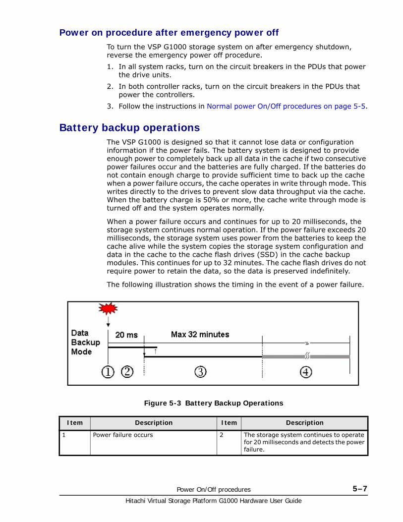
Power On/Off procedures 5–7Hitachi Virtual Storage Platform G1000 Hardware User Guide
Power on procedure after emergency power offTo turn the VSP G1000 storage system on after emergency shutdown, reverse the emergency power off procedure.
1. In all system racks, turn on the circuit breakers in the PDUs that power the drive units.
2. In both controller racks, turn on the circuit breakers in the PDUs that power the controllers.
3. Follow the instructions in Normal power On/Off procedures on page 5-5.
Battery backup operationsThe VSP G1000 is designed so that it cannot lose data or configuration information if the power fails. The battery system is designed to provide enough power to completely back up all data in the cache if two consecutive power failures occur and the batteries are fully charged. If the batteries do not contain enough charge to provide sufficient time to back up the cache when a power failure occurs, the cache operates in write through mode. This writes directly to the drives to prevent slow data throughput via the cache. When the battery charge is 50% or more, the cache write through mode is turned off and the system operates normally.
When a power failure occurs and continues for up to 20 milliseconds, the storage system continues normal operation. If the power failure exceeds 20 milliseconds, the storage system uses power from the batteries to keep the cache alive while the system copies the storage system configuration and data in the cache to the cache flash drives (SSD) in the cache backup modules. This continues for up to 32 minutes. The cache flash drives do not require power to retain the data, so the data is preserved indefinitely.
The following illustration shows the timing in the event of a power failure.
Figure 5-3 Battery Backup Operations
Item Description Item Description
1 Power failure occurs 2 The storage system continues to operate for 20 milliseconds and detects the power failure.
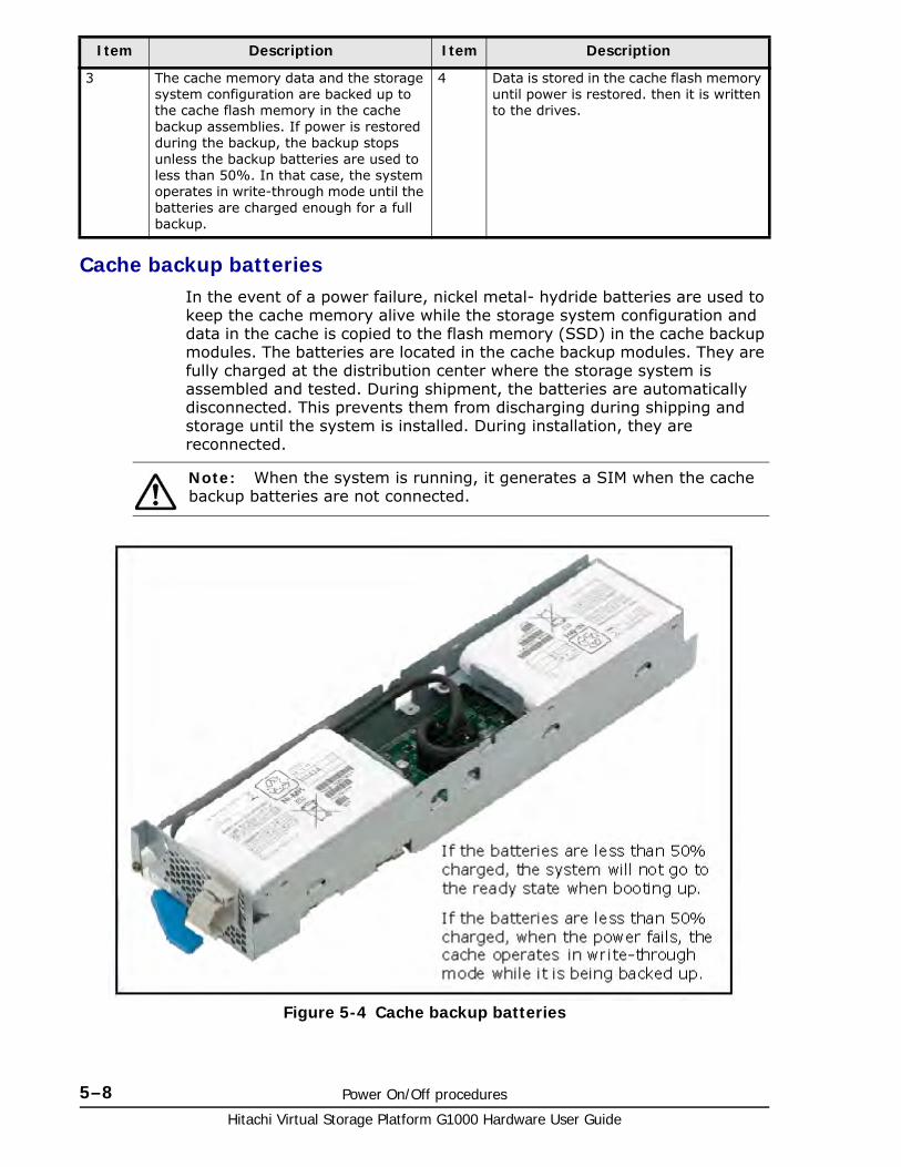
Hitachi Virtual Storage Platform G1000 Hardware User Guide
5–8 Power On/Off procedures
Cache backup batteriesIn the event of a power failure, nickel metal- hydride batteries are used to keep the cache memory alive while the storage system configuration and data in the cache is copied to the flash memory (SSD) in the cache backup modules. The batteries are located in the cache backup modules. They are fully charged at the distribution center where the storage system is assembled and tested. During shipment, the batteries are automatically disconnected. This prevents them from discharging during shipping and storage until the system is installed. During installation, they are reconnected.
3 The cache memory data and the storage system configuration are backed up to the cache flash memory in the cache backup assemblies. If power is restored during the backup, the backup stops unless the backup batteries are used to less than 50%. In that case, the system operates in write-through mode until the batteries are charged enough for a full backup.
4 Data is stored in the cache flash memory until power is restored. then it is written to the drives.
Item Description Item Description
Note: When the system is running, it generates a SIM when the cache backup batteries are not connected.
Figure 5-4 Cache backup batteries
Power On/Off procedures 5–9Hitachi Virtual Storage Platform G1000 Hardware User Guide
Battery life
The batteries have a lifespan of three years, and will hold a charge for that time when disconnected. When the batteries are connected and power is on, they are charged continuously. This occurs during both normal system operation and while the system is in idle mode.
When the batteries are connected and the power is off, the batteries slowly discharge. They will have a charge of less than 50% after two weeks without power. When fully discharged, the batteries must be connected to power for three hours to fully recharge.
Long term array storageWhile connected, the cache backup batteries will completely discharge in two to three weeks without power applied. If you do not use a VSP G1000 for two weeks or more, ask technical support to move the batteries to a storage system that is being used, or turn the storage system on to idle mode for at least 3 hours once every two weeks.
If you store the system for more than two weeks and do not disconnect the cache backup batteries, when you restart the system, the batteries will need to charge for at least 90 minutes before the cache will be protected. To prevent the batteries from discharging during long term storage, call technical support and ask them to disconnect the battery jumpers on the cache boards.
Note: The storage system generates a SIM when the cache backup batteries are not charged to at least 50%. The LEDs on the front panel of the cache backup kits also show the status of the batteries.

Hitachi Virtual Storage Platform G1000 Hardware User Guide
5–10 Power On/Off procedures
6
Troubleshooting 6–1Hitachi Virtual Storage Platform G1000 Hardware User Guide
Troubleshooting
This chapter provides troubleshooting information for the VSP G1000 storage system storage system.
□ Getting help
□ Solving problems
□ Service information messages
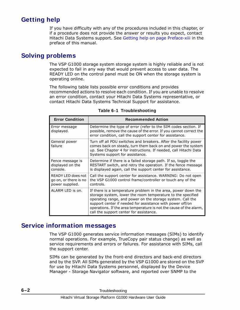
Hitachi Virtual Storage Platform G1000 Hardware User Guide
6–2 Troubleshooting
Getting helpIf you have difficulty with any of the procedures included in this chapter, or if a procedure does not provide the answer or results you expect, contact Hitachi Data Systems support. See Getting help on page Preface-xiii in the preface of this manual.
Solving problemsThe VSP G1000 storage system storage system is highly reliable and is not expected to fail in any way that would prevent access to user data. The READY LED on the control panel must be ON when the storage system is operating online.
The following table lists possible error conditions and provides recommended actions to resolve each condition. If you are unable to resolve an error condition, contact your Hitachi Data Systems representative, or contact Hitachi Data Systems Technical Support for assistance.
Table 6-1 Troubleshooting
Service information messagesThe VSP G1000 generates service information messages (SIMs) to identify normal operations. For example, TrueCopy pair status change) as well as service requirements and errors or failures. For assistance with SIMs, call the support center.
SIMs can be generated by the front-end directors and back-end directors and by the SVP. All SIMs generated by the VSP G1000 are stored on the SVP for use by Hitachi Data Systems personnel, displayed by the Device Manager - Storage Navigator software, and reported over SNMP to the
Error Condition Recommended Action
Error message displayed.
Determine the type of error (refer to the SIM codes section. If possible, remove the cause of the error. If you cannot correct the error condition, call the support center for assistance.
General power failure
Turn off all PDU switches and breakers. After the facility power comes back on steady, turn them back on and power the system up. See Chapter 4 for instructions. If needed, call Hitachi Data Systems support for assistance.
Fence message is displayed on the console.
Determine if there is a failed storage path. If so, toggle the RESTART switch, and retry the operation. If the fence message is displayed again, call the support center for assistance.
READY LED does not go on, or there is no power supplied.
Call the support center for assistance. WARNING: Do not open the VSP G1000 control frame/controller or touch any of the controls.
ALARM LED is on. If there is a temperature problem in the area, power down the storage system, lower the room temperature to the specified operating range, and power on the storage system. Call the support center if needed for assistance with power off/on operations. If the area temperature is not the cause of the alarm, call the support center for assistance.
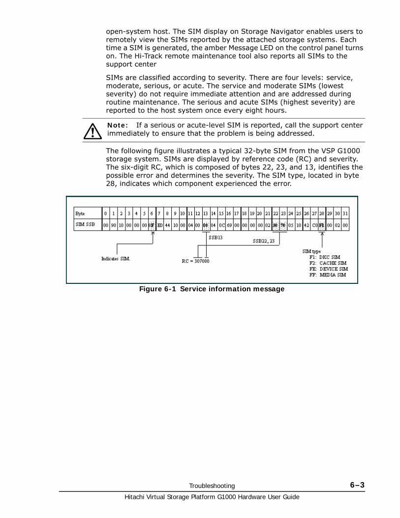
Troubleshooting 6–3Hitachi Virtual Storage Platform G1000 Hardware User Guide
open-system host. The SIM display on Storage Navigator enables users to remotely view the SIMs reported by the attached storage systems. Each time a SIM is generated, the amber Message LED on the control panel turns on. The Hi-Track remote maintenance tool also reports all SIMs to the support center
SIMs are classified according to severity. There are four levels: service, moderate, serious, or acute. The service and moderate SIMs (lowest severity) do not require immediate attention and are addressed during routine maintenance. The serious and acute SIMs (highest severity) are reported to the host system once every eight hours.
The following figure illustrates a typical 32-byte SIM from the VSP G1000 storage system. SIMs are displayed by reference code (RC) and severity. The six-digit RC, which is composed of bytes 22, 23, and 13, identifies the possible error and determines the severity. The SIM type, located in byte 28, indicates which component experienced the error.
Note: If a serious or acute-level SIM is reported, call the support center immediately to ensure that the problem is being addressed.
Figure 6-1 Service information message

Hitachi Virtual Storage Platform G1000 Hardware User Guide
6–4 Troubleshooting

A
Specifications A–1Hitachi Virtual Storage Platform G1000 Hardware User Guide
Specifications
This appendix provides the mechanical, electrical, and environmental specifications for the Hitachi Virtual Storage Platform G1000 storage system.
□ System specifications
□ Mechanical specifications
□ Electrical specifications
□ Environmental specifications
□ PDU specifications
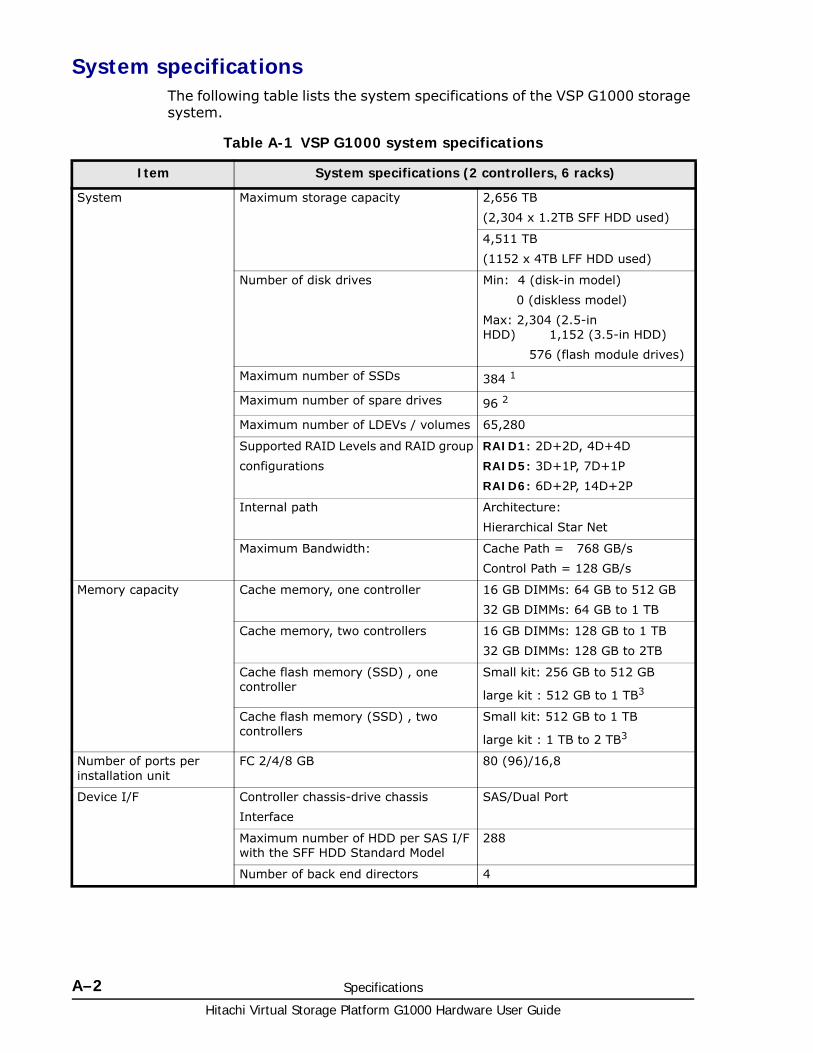
Hitachi Virtual Storage Platform G1000 Hardware User Guide
A–2 Specifications
System specificationsThe following table lists the system specifications of the VSP G1000 storage system.
Table A-1 VSP G1000 system specifications
Item System specifications (2 controllers, 6 racks)
System Maximum storage capacity 2,656 TB
(2,304 x 1.2TB SFF HDD used)
4,511 TB
(1152 x 4TB LFF HDD used)
Number of disk drives Min: 4 (disk-in model)
0 (diskless model)
Max: 2,304 (2.5-in HDD) 1,152 (3.5-in HDD)
576 (flash module drives)
Maximum number of SSDs 384 1
Maximum number of spare drives 96 2
Maximum number of LDEVs / volumes 65,280
Supported RAID Levels and RAID group
configurations
RAID1: 2D+2D, 4D+4D
RAID5: 3D+1P, 7D+1P
RAID6: 6D+2P, 14D+2P
Internal path Architecture:
Hierarchical Star Net
Maximum Bandwidth: Cache Path = 768 GB/s
Control Path = 128 GB/s
Memory capacity Cache memory, one controller 16 GB DIMMs: 64 GB to 512 GB
32 GB DIMMs: 64 GB to 1 TB
Cache memory, two controllers 16 GB DIMMs: 128 GB to 1 TB
32 GB DIMMs: 128 GB to 2TB
Cache flash memory (SSD) , one controller
Small kit: 256 GB to 512 GB
large kit : 512 GB to 1 TB3
Cache flash memory (SSD) , two controllers
Small kit: 512 GB to 1 TB
large kit : 1 TB to 2 TB3
Number of ports per installation unit
FC 2/4/8 GB 80 (96)/16,8
Device I/F Controller chassis-drive chassis
Interface
SAS/Dual Port
Maximum number of HDD per SAS I/F with the SFF HDD Standard Model
288
Number of back end directors 4
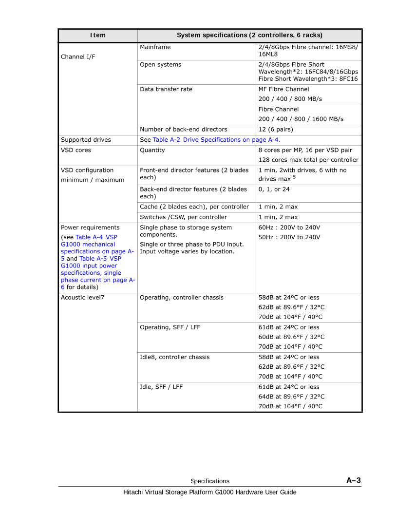
Specifications A–3Hitachi Virtual Storage Platform G1000 Hardware User Guide
Channel I/F
Mainframe 2/4/8Gbps Fibre channel: 16MS8/16ML8
Open systems 2/4/8Gbps Fibre Short Wavelength*2: 16FC84/8/16Gbps Fibre Short Wavelength*3: 8FC16
Data transfer rate MF Fibre Channel
200 / 400 / 800 MB/s
Fibre Channel
200 / 400 / 800 / 1600 MB/s
Number of back-end directors 12 (6 pairs)
Supported drives See Table A-2 Drive Specifications on page A-4.
VSD cores Quantity 8 cores per MP, 16 per VSD pair
128 cores max total per controller
VSD configuration
minimum / maximum
Front-end director features (2 blades each)
1 min, 2with drives, 6 with no drives max 5
Back-end director features (2 blades each)
0, 1, or 24
Cache (2 blades each), per controller 1 min, 2 max
Switches /CSW, per controller 1 min, 2 max
Power requirements
(see Table A-4 VSP G1000 mechanical specifications on page A-5 and Table A-5 VSP G1000 input power specifications, single phase current on page A-6 for details)
Single phase to storage system components.
Single or three phase to PDU input. Input voltage varies by location.
60Hz : 200V to 240V
50Hz : 200V to 240V
Acoustic level7 Operating, controller chassis 58dB at 24ºC or less
62dB at 89.6°F / 32°C
70dB at 104°F / 40°C
Operating, SFF / LFF 61dB at 24ºC or less
60dB at 89.6°F / 32°C
70dB at 104°F / 40°C
Idle8, controller chassis 58dB at 24ºC or less
62dB at 89.6°F / 32°C
70dB at 104°F / 40°C
Idle, SFF / LFF 61dB at 24°C or less
64dB at 89.6°F / 32°C
70dB at 104°F / 40°C
Item System specifications (2 controllers, 6 racks)
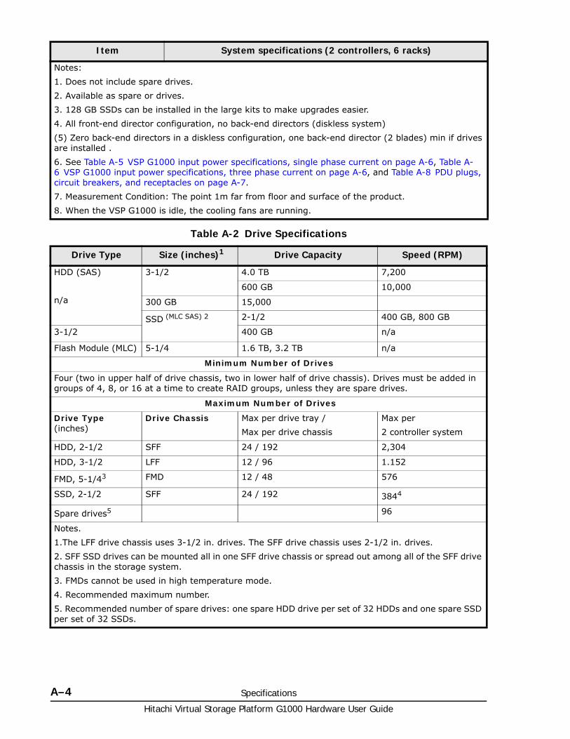
Hitachi Virtual Storage Platform G1000 Hardware User Guide
A–4 Specifications
Table A-2 Drive Specifications
Notes:
1. Does not include spare drives.
2. Available as spare or drives.
3. 128 GB SSDs can be installed in the large kits to make upgrades easier.
4. All front-end director configuration, no back-end directors (diskless system)
(5) Zero back-end directors in a diskless configuration, one back-end director (2 blades) min if drives are installed .
6. See Table A-5 VSP G1000 input power specifications, single phase current on page A-6, Table A-6 VSP G1000 input power specifications, three phase current on page A-6, and Table A-8 PDU plugs, circuit breakers, and receptacles on page A-7.
7. Measurement Condition: The point 1m far from floor and surface of the product.
8. When the VSP G1000 is idle, the cooling fans are running.
Drive Type Size (inches)1 Drive Capacity Speed (RPM)
HDD (SAS)
n/a
3-1/2 4.0 TB 7,200
600 GB 10,000
300 GB 15,000
SSD (MLC SAS) 2 2-1/2 400 GB, 800 GB
3-1/2 400 GB n/a
Flash Module (MLC) 5-1/4 1.6 TB, 3.2 TB n/a
Minimum Number of Drives
Four (two in upper half of drive chassis, two in lower half of drive chassis). Drives must be added in groups of 4, 8, or 16 at a time to create RAID groups, unless they are spare drives.
Maximum Number of Drives
Drive Type (inches)
Drive Chassis Max per drive tray /
Max per drive chassis
Max per
2 controller system
HDD, 2-1/2 SFF 24 / 192 2,304
HDD, 3-1/2 LFF 12 / 96 1.152
FMD, 5-1/43 FMD 12 / 48 576
SSD, 2-1/2 SFF 24 / 192 3844
Spare drives5 96
Notes.
1.The LFF drive chassis uses 3-1/2 in. drives. The SFF drive chassis uses 2-1/2 in. drives.
2. SFF SSD drives can be mounted all in one SFF drive chassis or spread out among all of the SFF drive chassis in the storage system.
3. FMDs cannot be used in high temperature mode.
4. Recommended maximum number.
5. Recommended number of spare drives: one spare HDD drive per set of 32 HDDs and one spare SSD per set of 32 SSDs.
Item System specifications (2 controllers, 6 racks)
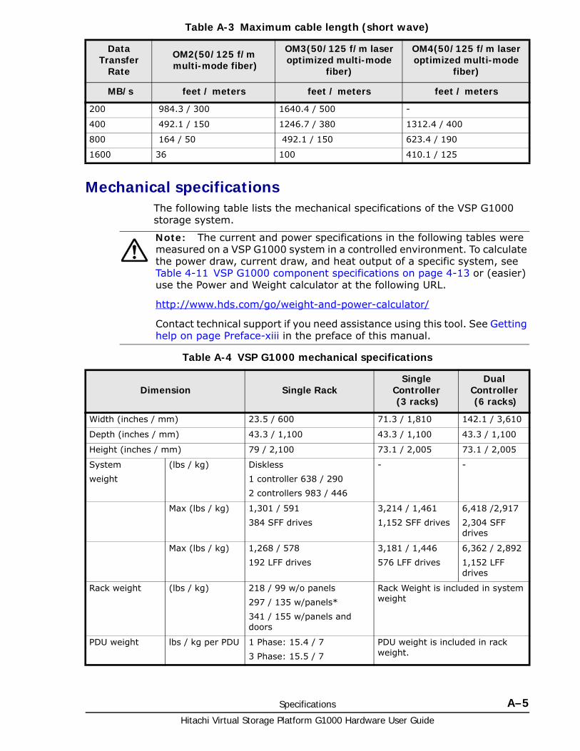
Specifications A–5Hitachi Virtual Storage Platform G1000 Hardware User Guide
Table A-3 Maximum cable length (short wave)
Mechanical specificationsThe following table lists the mechanical specifications of the VSP G1000 storage system.
Table A-4 VSP G1000 mechanical specifications
Data Transfer
Rate
OM2(50/125 f/m multi-mode fiber)
OM3(50/125 f/m laser optimized multi-mode
fiber)
OM4(50/125 f/m laser optimized multi-mode
fiber)
MB/s feet / meters feet / meters feet / meters
200 984.3 / 300 1640.4 / 500 -
400 492.1 / 150 1246.7 / 380 1312.4 / 400
800 164 / 50 492.1 / 150 623.4 / 190
1600 36 100 410.1 / 125
Note: The current and power specifications in the following tables were measured on a VSP G1000 system in a controlled environment. To calculate the power draw, current draw, and heat output of a specific system, see Table 4-11 VSP G1000 component specifications on page 4-13 or (easier) use the Power and Weight calculator at the following URL.
http://www.hds.com/go/weight-and-power-calculator/
Contact technical support if you need assistance using this tool. See Getting help on page Preface-xiii in the preface of this manual.
Dimension Single RackSingle
Controller (3 racks)
Dual Controller (6 racks)
Width (inches / mm) 23.5 / 600 71.3 / 1,810 142.1 / 3,610
Depth (inches / mm) 43.3 / 1,100 43.3 / 1,100 43.3 / 1,100
Height (inches / mm) 79 / 2,100 73.1 / 2,005 73.1 / 2,005
System
weight
(lbs / kg) Diskless
1 controller 638 / 290
2 controllers 983 / 446
- -
Max (lbs / kg) 1,301 / 591
384 SFF drives
3,214 / 1,461
1,152 SFF drives
6,418 /2,917
2,304 SFF drives
Max (lbs / kg) 1,268 / 578
192 LFF drives
3,181 / 1,446
576 LFF drives
6,362 / 2,892
1,152 LFF drives
Rack weight (lbs / kg) 218 / 99 w/o panels
297 / 135 w/panels*
341 / 155 w/panels and doors
Rack Weight is included in system weight
PDU weight lbs / kg per PDU 1 Phase: 15.4 / 7
3 Phase: 15.5 / 7
PDU weight is included in rack weight.
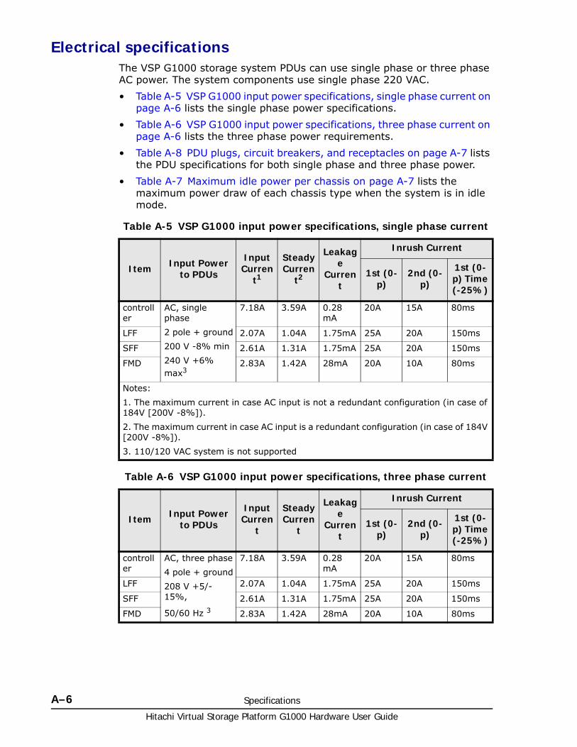
Hitachi Virtual Storage Platform G1000 Hardware User Guide
A–6 Specifications
Electrical specificationsThe VSP G1000 storage system PDUs can use single phase or three phase AC power. The system components use single phase 220 VAC.
• Table A-5 VSP G1000 input power specifications, single phase current on page A-6 lists the single phase power specifications.
• Table A-6 VSP G1000 input power specifications, three phase current on page A-6 lists the three phase power requirements.
• Table A-8 PDU plugs, circuit breakers, and receptacles on page A-7 lists the PDU specifications for both single phase and three phase power.
• Table A-7 Maximum idle power per chassis on page A-7 lists the maximum power draw of each chassis type when the system is in idle mode.
Table A-5 VSP G1000 input power specifications, single phase current
Table A-6 VSP G1000 input power specifications, three phase current
Item Input Powerto PDUs
Input Curren
t1
Steady Curren
t2
Leakage
Current
Inrush Current
1st (0-p)
2nd (0-p)
1st (0-p) Time (-25%)
controller
AC, single phase
2 pole + ground
200 V -8% min
240 V +6% max3
7.18A 3.59A 0.28 mA
20A 15A 80ms
LFF 2.07A 1.04A 1.75mA 25A 20A 150ms
SFF 2.61A 1.31A 1.75mA 25A 20A 150ms
FMD 2.83A 1.42A 28mA 20A 10A 80ms
Notes:
1. The maximum current in case AC input is not a redundant configuration (in case of 184V [200V -8%]).
2. The maximum current in case AC input is a redundant configuration (in case of 184V [200V -8%]).
3. 110/120 VAC system is not supported
Item Input Powerto PDUs
Input Curren
t
Steady Curren
t
Leakage
Current
Inrush Current
1st (0-p)
2nd (0-p)
1st (0-p) Time (-25%)
controller
AC, three phase
4 pole + ground
208 V +5/-15%,
50/60 Hz 3
7.18A 3.59A 0.28 mA
20A 15A 80ms
LFF 2.07A 1.04A 1.75mA 25A 20A 150ms
SFF 2.61A 1.31A 1.75mA 25A 20A 150ms
FMD 2.83A 1.42A 28mA 20A 10A 80ms
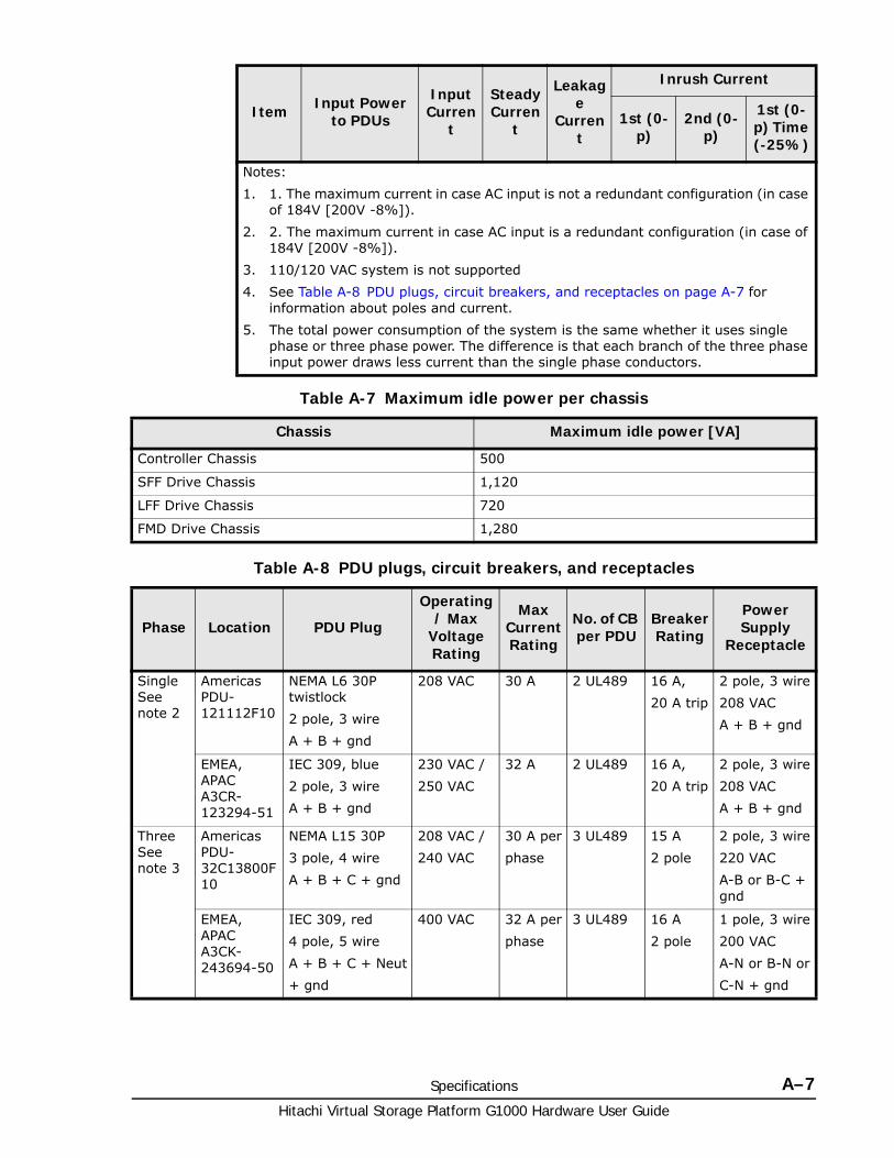
Specifications A–7Hitachi Virtual Storage Platform G1000 Hardware User Guide
Table A-7 Maximum idle power per chassis
Table A-8 PDU plugs, circuit breakers, and receptacles
Notes:
1. 1. The maximum current in case AC input is not a redundant configuration (in case of 184V [200V -8%]).
2. 2. The maximum current in case AC input is a redundant configuration (in case of 184V [200V -8%]).
3. 110/120 VAC system is not supported
4. See Table A-8 PDU plugs, circuit breakers, and receptacles on page A-7 for information about poles and current.
5. The total power consumption of the system is the same whether it uses single phase or three phase power. The difference is that each branch of the three phase input power draws less current than the single phase conductors.
Chassis Maximum idle power [VA]
Controller Chassis 500
SFF Drive Chassis 1,120
LFF Drive Chassis 720
FMD Drive Chassis 1,280
Phase Location PDU Plug
Operating / Max
Voltage Rating
Max Current Rating
No. of CB per PDU
Breaker Rating
Power Supply
Receptacle
Single See note 2
Americas PDU-121112F10
NEMA L6 30P twistlock
2 pole, 3 wire
A + B + gnd
208 VAC 30 A 2 UL489 16 A,
20 A trip
2 pole, 3 wire
208 VAC
A + B + gnd
EMEA, APAC A3CR-123294-51
IEC 309, blue
2 pole, 3 wire
A + B + gnd
230 VAC /
250 VAC
32 A 2 UL489 16 A,
20 A trip
2 pole, 3 wire
208 VAC
A + B + gnd
Three See note 3
Americas PDU-32C13800F10
NEMA L15 30P
3 pole, 4 wire
A + B + C + gnd
208 VAC /
240 VAC
30 A per
phase
3 UL489 15 A
2 pole
2 pole, 3 wire
220 VAC
A-B or B-C + gnd
EMEA, APAC A3CK-243694-50
IEC 309, red
4 pole, 5 wire
A + B + C + Neut
+ gnd
400 VAC 32 A per
phase
3 UL489 16 A
2 pole
1 pole, 3 wire
200 VAC
A-N or B-N or
C-N + gnd
Item Input Powerto PDUs
Input Curren
t
Steady Curren
t
Leakage
Current
Inrush Current
1st (0-p)
2nd (0-p)
1st (0-p) Time (-25%)
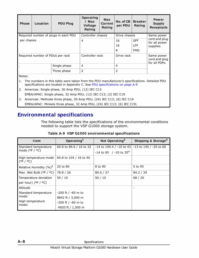
Hitachi Virtual Storage Platform G1000 Hardware User Guide
A–8 Specifications
Environmental specificationsThe following table lists the specifications of the environmental conditions needed to support the VSP G1000 storage system.
Table A-9 VSP G1000 environmental specifications
Required number of plugs in each PDU
per chassis
Controller chassis Drive chassis Same power cord and plug for all power supplies.
4 16
16
8
SFF
LFF
FMD
Required number of PDUs per rack Controller rack Drive rack Same power cord and plug for all PDPs.
. Single phase 4 4
Three phase 2 2
Notes:
1. The numbers in this table were taken from the PDU manufacturer’s specifications. Detailed PDU specifications are located in Appendix C. See PDU specifications on page A-9
2. Americas: Single phase, 30 Amp PDU, (12) IEC C13
EMEA/APAC: Single phase, 32 Amp PDU, (12) IEC C13; (2) IEC C19
3. Americas: Methode three phase, 30 Amp PDU, (24) IEC C13; (6) IEC C19
EMEA/APAC: Minkels three phase, 32 Amp PDU, (24) IEC C13; (6) IEC C19;
Phase Location PDU Plug
Operating / Max
Voltage Rating
Max Current Rating
No. of CB per PDU
Breaker Rating
Power Supply
Receptacle
Item Operating1 Not Operating2 Shipping & Storage3
Standard temperature mode (ºF / ºC)
60.8 to 89.6 / 16 to 32 -14 to 109.4 / -10 to 43
-14 to 95 / -10 to 354
-13 to 140 / -25 to 60
High temperature mode (ºF / ºC)
60.8 to 104 / 16 to 40
Relative Humidity (%)5 20 to 80 8 to 90 5 to 95
Max. Wet Bulb (ºF / ºC) 78.8 / 26 80.6 / 27 84.2 / 29
Temperature deviation
per hour) (ºF / ºC)
50 / 10 50 / 10 68 / 20
Altitude
Standard temperature mode:
High temperature mode:
-200 ft / -60 m to
9842 ft / 3,000 m
-200 ft / -60 m to
4920 ft / 1,500 m
-
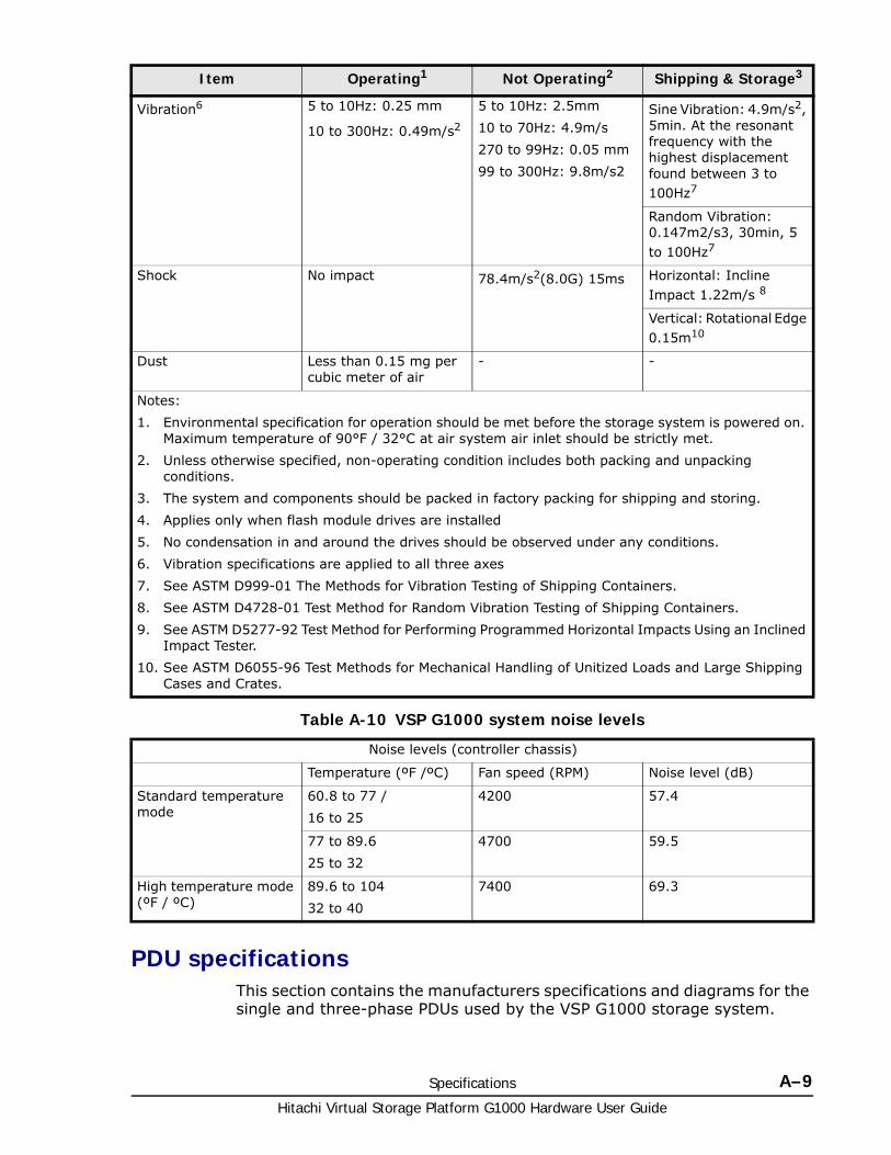
Specifications A–9Hitachi Virtual Storage Platform G1000 Hardware User Guide
Table A-10 VSP G1000 system noise levels
PDU specificationsThis section contains the manufacturers specifications and diagrams for the single and three-phase PDUs used by the VSP G1000 storage system.
Vibration6 5 to 10Hz: 0.25 mm
10 to 300Hz: 0.49m/s2
5 to 10Hz: 2.5mm
10 to 70Hz: 4.9m/s
270 to 99Hz: 0.05 mm
99 to 300Hz: 9.8m/s2
Sine Vibration: 4.9m/s2, 5min. At the resonant frequency with the highest displacement found between 3 to 100Hz7
Random Vibration: 0.147m2/s3, 30min, 5 to 100Hz7
Shock No impact 78.4m/s2(8.0G) 15ms Horizontal: Incline Impact 1.22m/s 8
Vertical: Rotational Edge 0.15m10
Dust Less than 0.15 mg per cubic meter of air
- -
Notes:
1. Environmental specification for operation should be met before the storage system is powered on. Maximum temperature of 90°F / 32°C at air system air inlet should be strictly met.
2. Unless otherwise specified, non-operating condition includes both packing and unpacking conditions.
3. The system and components should be packed in factory packing for shipping and storing.
4. Applies only when flash module drives are installed
5. No condensation in and around the drives should be observed under any conditions.
6. Vibration specifications are applied to all three axes
7. See ASTM D999-01 The Methods for Vibration Testing of Shipping Containers.
8. See ASTM D4728-01 Test Method for Random Vibration Testing of Shipping Containers.
9. See ASTM D5277-92 Test Method for Performing Programmed Horizontal Impacts Using an Inclined Impact Tester.
10. See ASTM D6055-96 Test Methods for Mechanical Handling of Unitized Loads and Large Shipping Cases and Crates.
Noise levels (controller chassis)
Temperature (ºF /ºC) Fan speed (RPM) Noise level (dB)
Standard temperature mode
60.8 to 77 /
16 to 25
4200 57.4
77 to 89.6
25 to 32
4700 59.5
High temperature mode (ºF / ºC)
89.6 to 104
32 to 40
7400 69.3
Item Operating1 Not Operating2 Shipping & Storage3
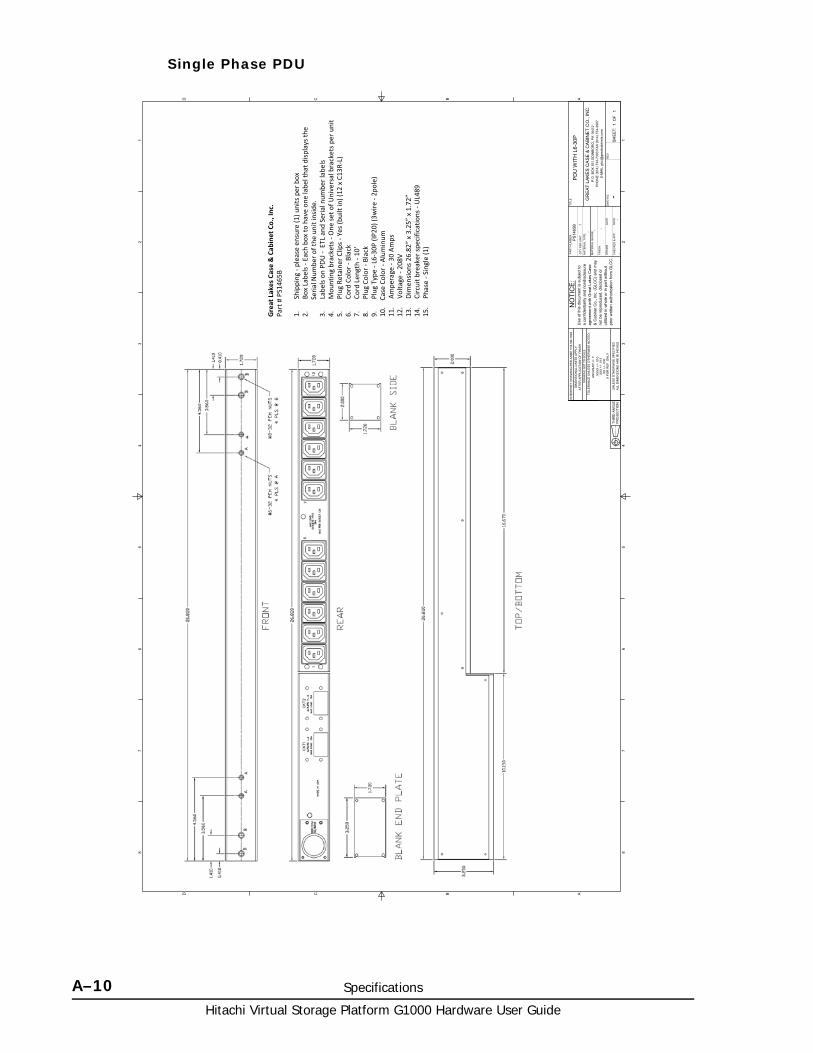
Hitachi Virtual Storage Platform G1000 Hardware User Guide
A–10 Specifications
Single Phase PDU
1 1
2 2
3 3
4 4
5 5
6 6
7 7
8 8
AA
BB
CC
DD
DW
G N
O:
RE
V
SH
EE
T:O
F
DR
AW
N
CH
ECK
ED &
AP
P.
TITL
E
DR
AWIN
G N
OT
TO S
CA
LE
PAR
T N
UM
BER
:
QTY
PER
UN
IT:
1M
ATE
RIA
L TY
PE:
MAT
ERIA
L G
AUG
E:
FIN
ISH
:
GR
EA
T LA
KE
S C
AS
E &
CA
BIN
ET
CO
., IN
C.
P.O
. BO
X 5
51 E
DIN
BOR
O, P
A 1
6412
PH
ON
E (8
14) 7
34-7
303
FAX
(814
) 734
-390
7E-
MA
IL g
lcc@
grea
tcab
inet
s.co
m
Use
of t
his
docu
men
t is
subj
ect t
oa
conf
iden
tialit
y an
d no
ndis
clos
ure
agre
emen
t with
Gre
at L
akes
Cas
e&
Cab
inet
Co.
, Inc
. (G
LCC
) and
may
not b
e re
prod
uced
, dis
clos
ed o
rut
ilize
d in
who
le o
r in
part
with
out
prio
r writ
ten
auth
oriz
atio
n fro
m G
LCC
.
NO
TIC
E:
TOLE
RA
NC
E U
NLE
SS O
THER
WIS
E N
OTE
D:
ANG
ULA
R +
/- 1�
.XX
XX
+/-
.010
.XX
X +
/- .0
15.X
X +
/- .0
30 .X
FO
R R
EF. O
NLY
UN
LESS
OTH
ERW
ISE
SPEC
IFIE
DA
LL D
IME
NSI
ON
S A
RE
IN IN
CH
ES
DIM
ENS
ION
AL
LIM
ITS
AP
PLY
AFT
ER A
PPL
ICAT
ION
OF
FIN
ISH
INTE
RP
RE
T D
RA
WIN
G P
ER
ASM
E Y
14.5
M-1
994
THIR
D A
NG
LEP
RO
JEC
TIO
N
DAT
E
DAT
E1
1
--
-
- - -
P
S14
65B
PD
U W
ITH
L6-
30P
Great�Lakes�Case�&�Cab
inet�Co.,�Inc.
Part�#�PS146
5B� 1.�������Shipp
ing���p
lease�en
sure�(1
)�units�per�box
2.�������Box�Labels���Each�bo
x�to�have�on
e�labe
l�that�d
isplays�th
e����������Serial�N
umbe
r�of�the
�unit�inside.
3.�������Labels�o
n�PD
U����ETL�and
�Serial�num
ber�labels
4.�������M
ounting�brackets���One
�set�o
f�Universal�brackets�p
er�unit
5.�������Plug�Re
tainer�Clips���Yes�(b
uilt�in)�(12
�x�C13
R�L)
6.�������Cord�Co
lor���Black
7.�������Cord�Length���10
'8.�������Plug�Co
lor���Black
9.�������Plug�Type
���L6�30P
�(IP2
0)�(3
wire
���2p
ole)
10.����Case�Co
lor���Aluminum
�11
.�����Am
perage���30�Amps
12.�����Vo
ltage���208V
13.�����Dimen
sions�26.82
”�x�3.25”�x�1.72
”14.�����Circuit�b
reaker�sp
ecificatio
ns���UL489
15.�����Ph
ase���Single�(1)
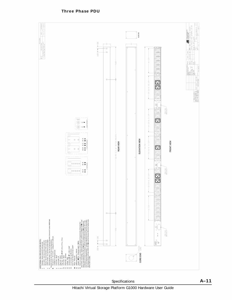
Specifications A–11Hitachi Virtual Storage Platform G1000 Hardware User Guide
Three Phase PDU

Hitachi Virtual Storage Platform G1000 Hardware User Guide
A–12 Specifications
B
Comparing VSP G1000 and VSP B–1Hitachi Virtual Storage Platform G1000 Hardware User Guide
Comparing VSP G1000 and VSP
This appendix provides a comparison of the main features of the Hitachi Virtual Storage Platform storage system and the Hitachi Virtual Storage Platform G1000 storage system.
□ Comparison of VSP and VSP G1000
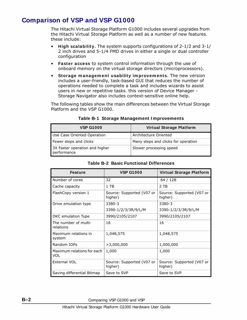
Hitachi Virtual Storage Platform G1000 Hardware User Guide
B–2 Comparing VSP G1000 and VSP
Comparison of VSP and VSP G1000The Hitachi Virtual Storage Platform G1000 includes several upgrades from the Hitachi Virtual Storage Platform as well as a number of new features. these include:
• High scalability. The system supports configurations of 2-1/2 and 3-1/2 inch drives and 5-1/4 FMD drives in either a single or dual controller configuration
• Faster access to system control information through the use of onboard memory on the virtual storage directors (microprocessors).
• Storage management usability improvements. The new version includes a user-friendly, task-based GUI that reduces the number of operations needed to complete a task and includes wizards to assist users in new or repetitive tasks. this version of Device Manager - Storage Navigator also includes context-sensitive online help.
The following tables show the main differences between the Virtual Storage Platform and the VSP G1000.
Table B-1 Storage Management Improvements
Table B-2 Basic Functional Differences
VSP G1000 Virtual Storage Platform
Use Case Oriented Operation Architecture Oriented
Fewer steps and clicks Many steps and clicks for operation
3X Faster operation and higher performance
Slower processing speed
Feature VSP G1000 Virtual Storage Platform
Number of cores 32 64 / 128
Cache capacity 1 TB 2 TB
FlashCopy version 1 Source: Supported (V07 or higher)
Source: Supported (V07 or higher)
Drive emulation type 3380-3
3390-1/2/3/3R/9/L/M
3380-3
3390-1/2/3/3R/9/L/M
DKC emulation Type 3990/2105/2107 3990/2105/2107
The number of multi-relations
16 16
Maximum relations in system
1,048,575 1,048,575
Random IOPs >3,000,000 1,000,000
Maximum relations for each VOL
1,000 1,000
External VOL Source: Supported (V07 or higher)
Source: Supported (V07 or higher)
Saving differential Bitmap Save to SVP Save to SVP
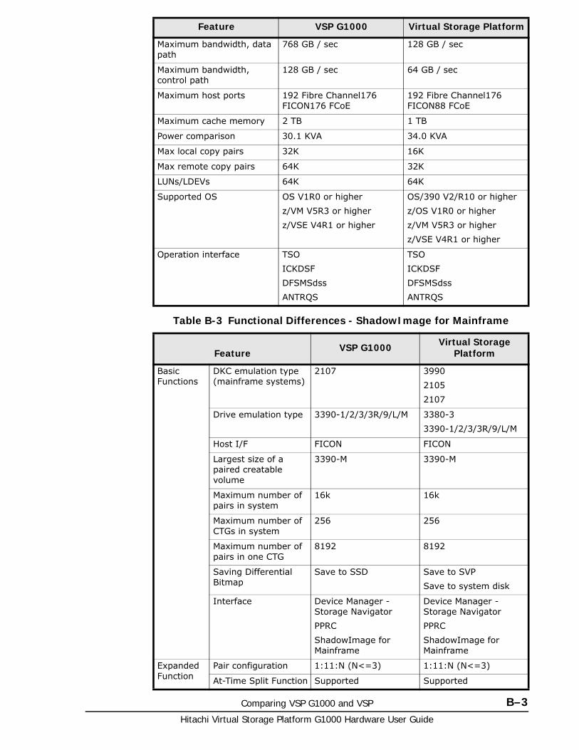
Comparing VSP G1000 and VSP B–3Hitachi Virtual Storage Platform G1000 Hardware User Guide
Table B-3 Functional Differences - ShadowImage for Mainframe
Maximum bandwidth, data path
768 GB / sec 128 GB / sec
Maximum bandwidth, control path
128 GB / sec 64 GB / sec
Maximum host ports 192 Fibre Channel176 FICON176 FCoE
192 Fibre Channel176 FICON88 FCoE
Maximum cache memory 2 TB 1 TB
Power comparison 30.1 KVA 34.0 KVA
Max local copy pairs 32K 16K
Max remote copy pairs 64K 32K
LUNs/LDEVs 64K 64K
Supported OS OS V1R0 or higher
z/VM V5R3 or higher
z/VSE V4R1 or higher
OS/390 V2/R10 or higher
z/OS V1R0 or higher
z/VM V5R3 or higher
z/VSE V4R1 or higher
Operation interface TSO
ICKDSF
DFSMSdss
ANTRQS
TSO
ICKDSF
DFSMSdss
ANTRQS
Feature VSP G1000 Virtual Storage Platform
Basic Functions
DKC emulation type (mainframe systems)
2107 3990
2105
2107
Drive emulation type 3390-1/2/3/3R/9/L/M 3380-3
3390-1/2/3/3R/9/L/M
Host I/F FICON FICON
Largest size of a paired creatable volume
3390-M 3390-M
Maximum number of pairs in system
16k 16k
Maximum number of CTGs in system
256 256
Maximum number of pairs in one CTG
8192 8192
Saving Differential Bitmap
Save to SSD Save to SVP
Save to system disk
Interface Device Manager - Storage Navigator
PPRC
ShadowImage for Mainframe
Device Manager - Storage Navigator
PPRC
ShadowImage for Mainframe
Expanded Function
Pair configuration 1:11:N (N<=3) 1:11:N (N<=3)
At-Time Split Function Supported Supported
Feature VSP G1000 Virtual Storage Platform
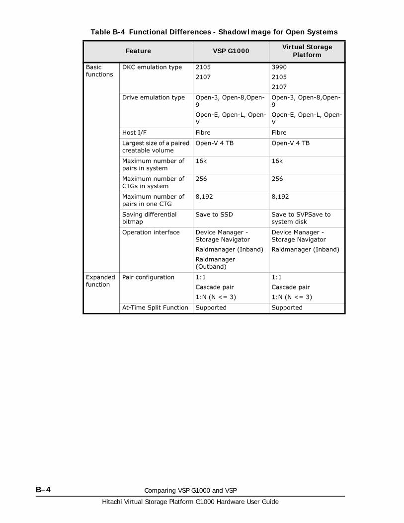
Hitachi Virtual Storage Platform G1000 Hardware User Guide
B–4 Comparing VSP G1000 and VSP
Table B-4 Functional Differences - ShadowImage for Open Systems
Feature VSP G1000 Virtual Storage Platform
Basic functions
DKC emulation type 2105
2107
3990
2105
2107
Drive emulation type Open-3, Open-8,Open-9
Open-E, Open-L, Open-V
Open-3, Open-8,Open-9
Open-E, Open-L, Open-V
Host I/F Fibre Fibre
Largest size of a paired creatable volume
Open-V 4 TB Open-V 4 TB
Maximum number of pairs in system
16k 16k
Maximum number of CTGs in system
256 256
Maximum number of pairs in one CTG
8,192 8,192
Saving differential bitmap
Save to SSD Save to SVPSave to system disk
Operation interface Device Manager - Storage Navigator
Raidmanager (Inband)
Raidmanager (Outband)
Device Manager - Storage Navigator
Raidmanager (Inband)
Expanded function
Pair configuration 1:1
Cascade pair
1:N (N <= 3)
1:1
Cascade pair
1:N (N <= 3)
At-Time Split Function Supported Supported
C
Rack information C–1Hitachi Virtual Storage Platform G1000 Hardware User Guide
Rack information
This appendix provides the specifications for the Hitachi standard 19-inch “Universal” rack and the specifications that a customer-supplied rack must meet to support a Hitachi Virtual Storage Platform G1000 storage system.
□ About the Hitachi Universal rack
□ Before installing a rack or equipment
□ Installation safety
□ Working with racks or components in the rack
□ Preparing for installation
□ Installing a Hitachi Universal rack
□ Post-installation considerations
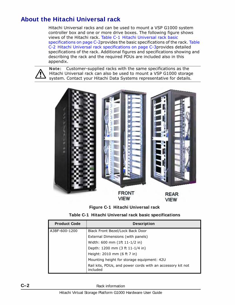
Hitachi Virtual Storage Platform G1000 Hardware User Guide
C–2 Rack information
About the Hitachi Universal rackHitachi Universal racks and can be used to mount a VSP G1000 system controller box and one or more drive boxes. The following figure shows views of the Hitachi rack. Table C-1 Hitachi Universal rack basic specifications on page C-2provides the basic specifications of the rack. Table C-2 Hitachi Universal rack specifications on page C-3provides detailed specifications of the rack. Additional figures and specifications showing and describing the rack and the required PDUs are included also in this appendix.
Table C-1 Hitachi Universal rack basic specifications
Note: Customer-supplied racks with the same specifications as the Hitachi Universal rack can also be used to mount a VSP G1000 storage system. Contact your Hitachi Data Systems representative for details.
Figure C-1 Hitachi Universal rack
Product Code Description
A3BF-600-1200 Black Front Bezel/Lock Back Door
External Dimensions (with panels)
Width: 600 mm (1ft 11-1/2 in)
Depth: 1200 mm (3 ft 11-1/4 in)
Height: 2010 mm (6 ft 7 in)
Mounting height for storage equipment: 42U
Rail kits, PDUs, and power cords with an accessory kit not included
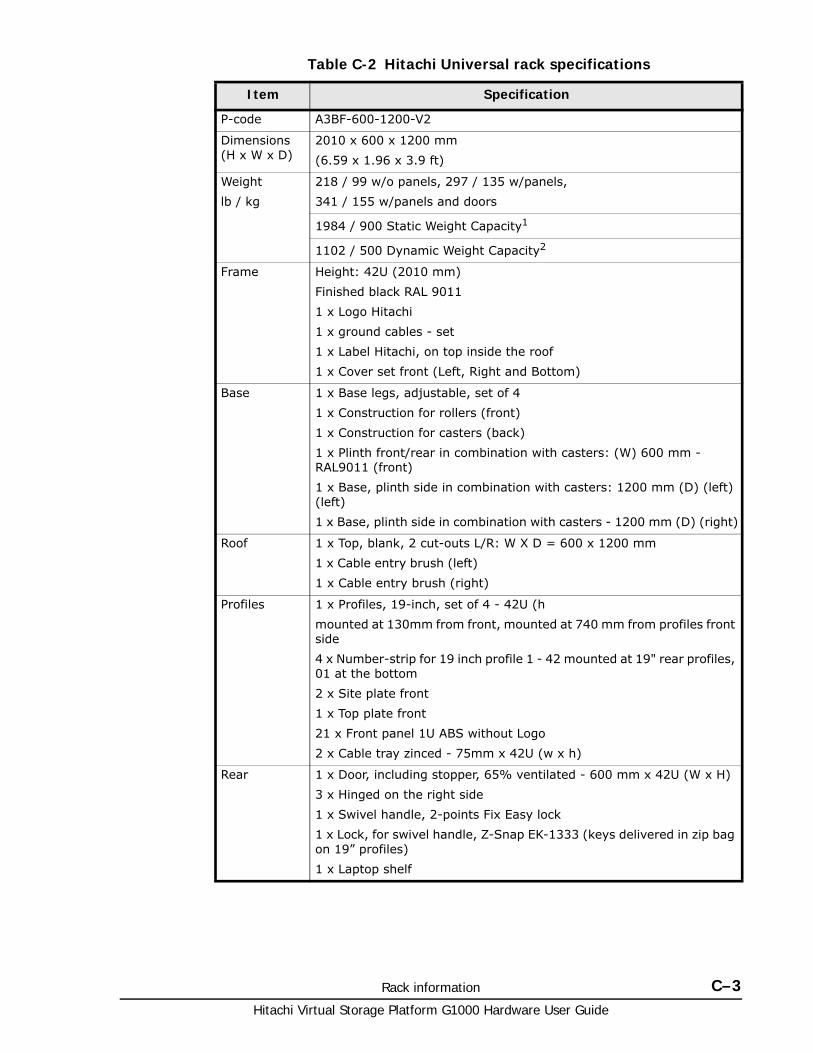
Rack information C–3Hitachi Virtual Storage Platform G1000 Hardware User Guide
Table C-2 Hitachi Universal rack specifications
Item Specification
P-code A3BF-600-1200-V2
Dimensions (H x W x D)
2010 x 600 x 1200 mm
(6.59 x 1.96 x 3.9 ft)
Weight
lb / kg
218 / 99 w/o panels, 297 / 135 w/panels,
341 / 155 w/panels and doors
1984 / 900 Static Weight Capacity1
1102 / 500 Dynamic Weight Capacity2
Frame Height: 42U (2010 mm)
Finished black RAL 9011
1 x Logo Hitachi
1 x ground cables - set
1 x Label Hitachi, on top inside the roof
1 x Cover set front (Left, Right and Bottom)
Base 1 x Base legs, adjustable, set of 4
1 x Construction for rollers (front)
1 x Construction for casters (back)
1 x Plinth front/rear in combination with casters: (W) 600 mm - RAL9011 (front)
1 x Base, plinth side in combination with casters: 1200 mm (D) (left) (left)
1 x Base, plinth side in combination with casters - 1200 mm (D) (right)
Roof 1 x Top, blank, 2 cut-outs L/R: W X D = 600 x 1200 mm
1 x Cable entry brush (left)
1 x Cable entry brush (right)
Profiles 1 x Profiles, 19-inch, set of 4 - 42U (h
mounted at 130mm from front, mounted at 740 mm from profiles front side
4 x Number-strip for 19 inch profile 1 - 42 mounted at 19" rear profiles, 01 at the bottom
2 x Site plate front
1 x Top plate front
21 x Front panel 1U ABS without Logo
2 x Cable tray zinced - 75mm x 42U (w x h)
Rear 1 x Door, including stopper, 65% ventilated - 600 mm x 42U (W x H)
3 x Hinged on the right side
1 x Swivel handle, 2-points Fix Easy lock
1 x Lock, for swivel handle, Z-Snap EK-1333 (keys delivered in zip bag on 19” profiles)
1 x Laptop shelf
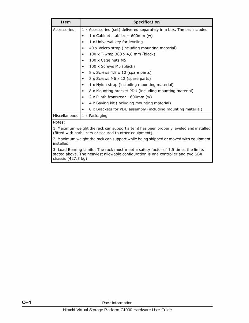
Hitachi Virtual Storage Platform G1000 Hardware User Guide
C–4 Rack information
Accessories 1 x Accessories (set) delivered separately in a box. The set includes:
• 1 x Cabinet stabilizer- 600mm (w)
• 1 x Universal key for leveling
• 40 x Velcro strap (including mounting material)
• 100 x T-wrap 360 x 4,8 mm (black)
• 100 x Cage nuts M5
• 100 x Screws M5 (black)
• 8 x Screws 4.8 x 10 (spare parts)
• 8 x Screws M6 x 12 (spare parts)
• 1 x Nylon strap (including mounting material)
• 8 x Mounting bracket PDU (including mounting material)
• 2 x Plinth front/rear - 600mm (w)
• 4 x Baying kit (including mounting material)
• 8 x Brackets for PDU assembly (including mounting material)
Miscellaneous 1 x Packaging
Notes:
1. Maximum weight the rack can support after it has been properly leveled and installed (fitted with stabilizers or secured to other equipment).
2. Maximum weight the rack can support while being shipped or moved with equipment installed.
3. Load Bearing Limits: The rack must meet a safety factor of 1.5 times the limits stated above. The heaviest allowable configuration is one controller and two SBX chassis (427.5 kg)
Item Specification
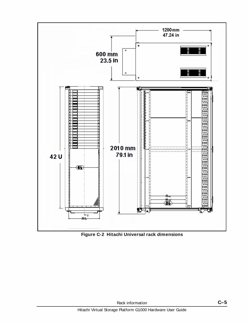
Rack information C–5Hitachi Virtual Storage Platform G1000 Hardware User Guide
Figure C-2 Hitachi Universal rack dimensions
Hitachi Virtual Storage Platform G1000 Hardware User Guide
C–6 Rack information
Power considerationsThe Hitachi rack is wired to make 200-240V available for the components with four PDUs. The input power to the PDUs varies with location and may be single or three phase. See Table A-8 PDU plugs, circuit breakers, and receptacles on page A-7 and Table A-5 VSP G1000 input power specifications, single phase current on page A-6 for details.
• The rack assembled for use with single phase power in the Americas comes with four preinstalled 121112F10 30-amp PDUs and a 10-foot power cord. The PDUs are rated for 208VAC, 50/60 Hz, 30 amps, derated to 80% for continued use (24 amps).
• The rack assembled for use in the EMEA / APAC comes with four preinstalled 32-amp PDUs and a 10-foot power cord.
Maximum current load. When connecting devices to the PDUs, do not exceed 12 amps per bank of four receptacles, and do not exceed 24 amps per PDU. Follow the guidelines for PDU load as specified in the appropriate Hitachi Data Systems installation documentation. To ensure maximum system availability, each PDU requires a dedicated 30A circuit. For example, a system with four PDUs, each with a 30A L630P plug, requires four 30A circuits.
To ensure maximum system availability, each PDU requires a dedicated 30A circuit. For example, a system with four PDUs, each with a 30A L630P plug, requires four 30A circuits.
Before installing third-party components in the rack, determine the current draw of each component and compare that with the allowable current load on each PDU to determine if the component can be plugged into a PDU.
To reduce the risk of injury, fire, or damage to persons or equipment, do not exceed the maximum usable amperage per PDU. Consult the electrical authority having jurisdiction over your facility's wiring and installation requirements. When planning for power distribution and requirements for your rack configuration, note the following:
• Balance the current load between available PDUs.
• The current load on each PDU must not exceed 80% of the PDU current rating (that is, the maximum amperage is 80% of the 30 amp PDUs, allowing for a maximum of 24 usable amps per PDU).
If an uninterruptable power supply (UPS) is used, the load should not exceed 80% of the UPS devices marked electrical current rating.
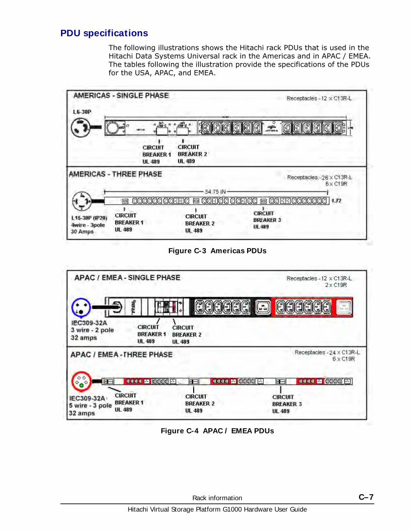
Rack information C–7Hitachi Virtual Storage Platform G1000 Hardware User Guide
PDU specificationsThe following illustrations shows the Hitachi rack PDUs that is used in the Hitachi Data Systems Universal rack in the Americas and in APAC / EMEA. The tables following the illustration provide the specifications of the PDUs for the USA, APAC, and EMEA.
Figure C-3 Americas PDUs
Figure C-4 APAC / EMEA PDUs
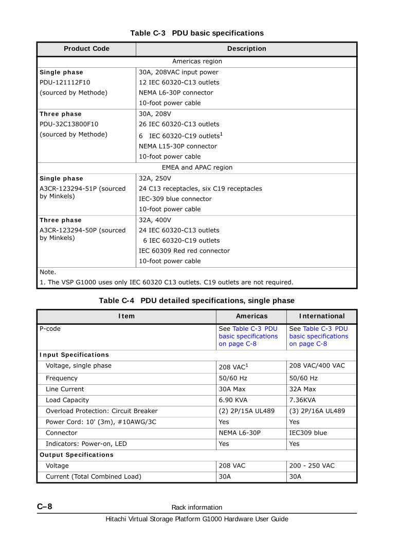
Hitachi Virtual Storage Platform G1000 Hardware User Guide
C–8 Rack information
Table C-3 PDU basic specifications
Table C-4 PDU detailed specifications, single phase
Product Code Description
Americas region
Single phase
PDU-121112F10
(sourced by Methode)
30A, 208VAC input power
12 IEC 60320-C13 outlets
NEMA L6-30P connector
10-foot power cable
Three phase
PDU-32C13800F10
(sourced by Methode)
30A, 208V
26 IEC 60320-C13 outlets
6 IEC 60320-C19 outlets1
NEMA L15-30P connector
10-foot power cable
EMEA and APAC region
Single phase
A3CR-123294-51P (sourced by Minkels)
32A, 250V
24 C13 receptacles, six C19 receptacles
IEC-309 blue connector
10-foot power cable
Three phase
A3CR-123294-50P (sourced by Minkels)
32A, 400V
24 IEC 60320-C13 outlets
6 IEC 60320-C19 outlets
IEC 60309 Red red connector
10-foot power cable
Note.
1. The VSP G1000 uses only IEC 60320 C13 outlets. C19 outlets are not required.
Item Americas International
P-code See Table C-3 PDU basic specifications on page C-8
See Table C-3 PDU basic specifications on page C-8
Input Specifications
Voltage, single phase 208 VAC1 208 VAC/400 VAC
Frequency 50/60 Hz 50/60 Hz
Line Current 30A Max 32A Max
Load Capacity 6.90 KVA 7.36KVA
Overload Protection: Circuit Breaker (2) 2P/15A UL489 (3) 2P/16A UL489
Power Cord: 10' (3m), #10AWG/3C Yes Yes
Connector NEMA L6-30P IEC309 blue
Indicators: Power-on, LED Yes Yes
Output Specifications
Voltage 208 VAC 200 - 250 VAC
Current (Total Combined Load) 30A 30A
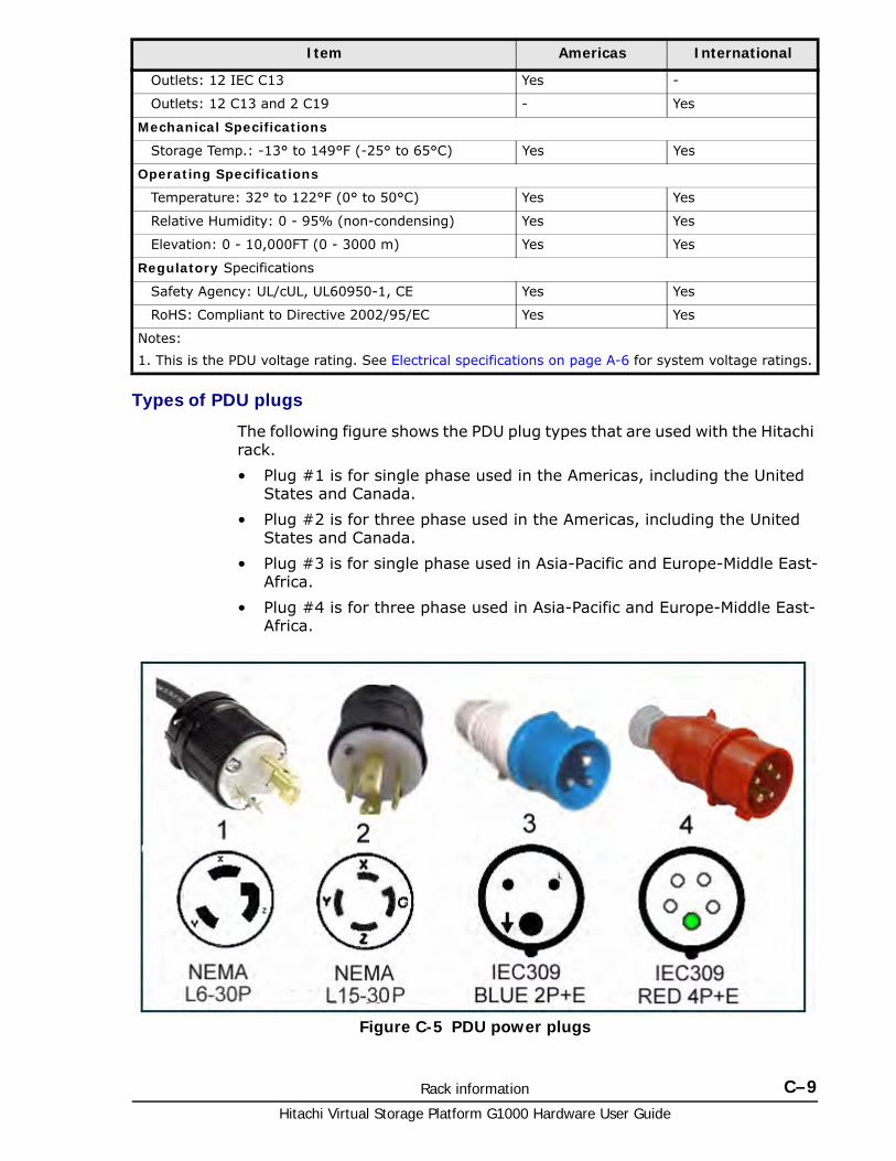
Rack information C–9Hitachi Virtual Storage Platform G1000 Hardware User Guide
Types of PDU plugs
The following figure shows the PDU plug types that are used with the Hitachi rack.
• Plug #1 is for single phase used in the Americas, including the United States and Canada.
• Plug #2 is for three phase used in the Americas, including the United States and Canada.
• Plug #3 is for single phase used in Asia-Pacific and Europe-Middle East-Africa.
• Plug #4 is for three phase used in Asia-Pacific and Europe-Middle East-Africa.
Outlets: 12 IEC C13 Yes -
Outlets: 12 C13 and 2 C19 - Yes
Mechanical Specifications
Storage Temp.: -13° to 149°F (-25° to 65°C) Yes Yes
Operating Specifications
Temperature: 32° to 122°F (0° to 50°C) Yes Yes
Relative Humidity: 0 - 95% (non-condensing) Yes Yes
Elevation: 0 - 10,000FT (0 - 3000 m) Yes Yes
Regulatory Specifications
Safety Agency: UL/cUL, UL60950-1, CE Yes Yes
RoHS: Compliant to Directive 2002/95/EC Yes Yes
Notes:
1. This is the PDU voltage rating. See Electrical specifications on page A-6 for system voltage ratings.
Item Americas International
Figure C-5 PDU power plugs
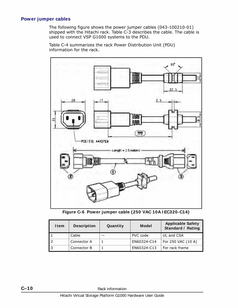
Hitachi Virtual Storage Platform G1000 Hardware User Guide
C–10 Rack information
Power jumper cables
The following figure shows the power jumper cables (043-100210-01) shipped with the Hitachi rack. Table C-3 describes the cable. The cable is used to connect VSP G1000 systems to the PDU.
Table C-4 summarizes the rack Power Distribution Unit (PDU) information for the rack.
Figure C-6 Power jumper cable (250 VAC 10A IEC320-C14)
Item Description Quantity Model Applicable Safety Standard / Rating
1 Cable — PVC code UL and CSA
2 Connector A 1 EN60324-C14 For 250 VAC (10 A)
3 Connector B 1 EN60324-C13 For rack frame
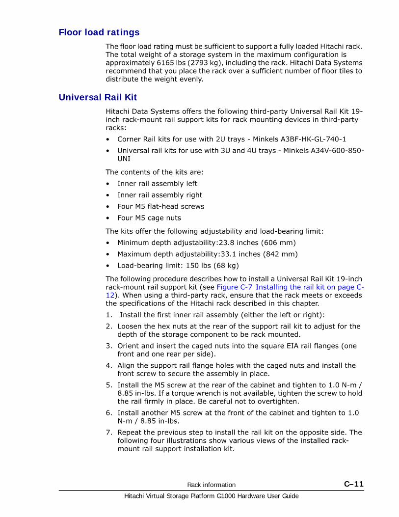
Rack information C–11Hitachi Virtual Storage Platform G1000 Hardware User Guide
Floor load ratingsThe floor load rating must be sufficient to support a fully loaded Hitachi rack. The total weight of a storage system in the maximum configuration is approximately 6165 lbs (2793 kg), including the rack. Hitachi Data Systems recommend that you place the rack over a sufficient number of floor tiles to distribute the weight evenly.
Universal Rail KitHitachi Data Systems offers the following third-party Universal Rail Kit 19-inch rack-mount rail support kits for rack mounting devices in third-party racks:
• Corner Rail kits for use with 2U trays - Minkels A3BF-HK-GL-740-1
• Universal rail kits for use with 3U and 4U trays - Minkels A34V-600-850-UNI
The contents of the kits are:
• Inner rail assembly left
• Inner rail assembly right
• Four M5 flat-head screws
• Four M5 cage nuts
The kits offer the following adjustability and load-bearing limit:
• Minimum depth adjustability:23.8 inches (606 mm)
• Maximum depth adjustability:33.1 inches (842 mm)
• Load-bearing limit: 150 lbs (68 kg)
The following procedure describes how to install a Universal Rail Kit 19-inch rack-mount rail support kit (see Figure C-7 Installing the rail kit on page C-12). When using a third-party rack, ensure that the rack meets or exceeds the specifications of the Hitachi rack described in this chapter.
1. Install the first inner rail assembly (either the left or right):
2. Loosen the hex nuts at the rear of the support rail kit to adjust for the depth of the storage component to be rack mounted.
3. Orient and insert the caged nuts into the square EIA rail flanges (one front and one rear per side).
4. Align the support rail flange holes with the caged nuts and install the front screw to secure the assembly in place.
5. Install the M5 screw at the rear of the cabinet and tighten to 1.0 N-m / 8.85 in-lbs. If a torque wrench is not available, tighten the screw to hold the rail firmly in place. Be careful not to overtighten.
6. Install another M5 screw at the front of the cabinet and tighten to 1.0 N-m / 8.85 in-lbs.
7. Repeat the previous step to install the rail kit on the opposite side. The following four illustrations show various views of the installed rack-mount rail support installation kit.
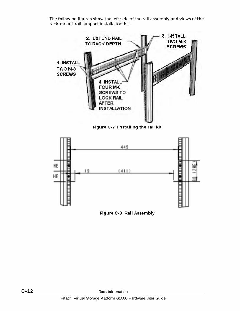
Hitachi Virtual Storage Platform G1000 Hardware User Guide
C–12 Rack information
The following figures show the left side of the rail assembly and views of the rack-mount rail support installation kit.
Figure C-7 Installing the rail kit
Figure C-8 Rail Assembly
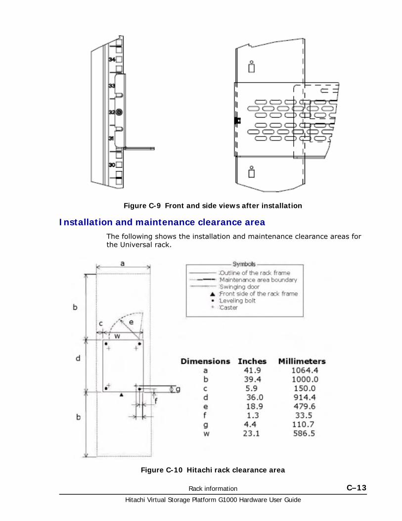
Rack information C–13Hitachi Virtual Storage Platform G1000 Hardware User Guide
Installation and maintenance clearance areaThe following shows the installation and maintenance clearance areas for the Universal rack.
Figure C-9 Front and side views after installation
Figure C-10 Hitachi rack clearance area
Hitachi Virtual Storage Platform G1000 Hardware User Guide
C–14 Rack information
Before installing a rack or equipmentBefore unpacking, moving, or installing a rack or any equipment in it, read the following safety information. If yo have any questions, contact appropriate personnel within your company and as needed, contact Hitachi Data Systems Technical Support.
Safety precautionsTo prevent bodily injury when mounting or servicing the storage system in the rack, take special precautions to ensure that the storage system racks and equipment remains stable.
• Do not do anything that creates a potential hazard to people or that makes the equipment or rack unsafe.
• Mount the storage system starting from the bottom of the rack. If the rack will be partially filled, mount the heaviest component at the bottom of the rack. If the storage system is mounted only near the top of the rack, the rack may become unstable and fall
• Adjust the position of the storage system components so that they are mounted horizontally in the center of the rack frame. Shift the storage system onto the rails in the rack frame. When shifting the storage system, push it in to the end gently.
• The Hitachi rack is equipped with wheels for moving. Use enough personnel when moving the cabinet, especially on sloping loading docks and ramps to raised computer room floors. Move the cabinet slowly and deliberately. Be sure the floor is free from foreign objects and cables that the cabinet could roll over.
Electrical and environmental requirementsThe following are basic data center requirements for installing and operating a VSP G1000 storage system in a Hitachi rack. Detailed specifications and requirements are listed in Specifications on page A-1.
• The AC supply circuit for rack-mounted equipment must supply the total current specified on all the labels of the rack-mounted equipment and as specified in this guide.
• All AC power supply connections to the rack must be properly grounded. To ensure the integrity of the ground connection, special attention must be given to connections that are not directly connected to the branch circuit (for example, power strips).
• The operating ambient temperature of rack-mounted equipment must not exceed the maximum rated ambient temperature indicated in this guide.
• Air flow clearances specified in this guide must be maintained within the rack.
WARNING: The VSP G1000 storage system equipment is very heavy. Use a mechanical lifter to lift, move, install, and remove storage system equipment in a rack. If a piece of equipment falls, it could not cause serious personal injury. Be careful when lifting, handling, positioning, and fastening equipment in a rack.
Rack information C–15Hitachi Virtual Storage Platform G1000 Hardware User Guide
Installation safety• When power is fed from a wall or floor outlet, unplug the power supply
cord, or turn off the switch on the power distribution panel or board.
• Attach a notice on the panel or board prohibiting the use of the switch. If the rack-mounted components have already had their power turned off, be sure these conditions are satisfied.
• Do not touch any uninsulated conductor or surface which may remain charged for a limited time after the external power supply to a rack-mounted component is disconnected.
• If working on a rack-mounted component that has a grounding terminal, be sure the terminal is properly connected to the facility’s ground.
• If working near a hazardously energized part, do not work alone. Work with another person who can immediately turn off the power in an emergency.
• Do not wear any metallic item such as a wristwatch with a metallic surface or metallic accessories. If you wear eyeglasses with a metallic frame, do not allow the frame to touch an uninsulated surface.
• Be sure your hands and arms are dry.
• Unless otherwise specifically instructed, use only one hand when it is necessary to work near an exposed live electric circuit. This prevents the completion of the circuit through both hands even if you accidentally touch the circuit.
• Do not use a dental mirror near an exposed live electric circuit. The mirror surface is conductive and can become hazardous even if it is made of plastic.
• Unless otherwise specifically instructed, do not supply power to any subassembly such as a power supply unit or a motor while it is removed from its main product.
Precautions when using rack-mounted equipmentThis section explains precautions for:
• Casters — see Casters on page C-16
• Rack stability — see Rack stability on page C-16
• Component weight and location — see Component weight and location on page C-16
• Height considerations — see Height considerations on page C-17
• Placing components in the rack — see Placing components in the rack on page C-18
• Working with racks or components — see Working with racks or components in the rack on page C-18
• Air vents and airflow — see Air vents and airflow on page C-19
• Blanking panels — see Blanking panels on page C-19
• Cable Guidelines — see Cable guidelines on page C-19
Hitachi Virtual Storage Platform G1000 Hardware User Guide
C–16 Rack information
Casters
Hitachi racks have casters that enable the rack to be rolled across short distances to position it for final installation. Although the casters can support the weight of the rack with installed components, they are not designed to support the full weight of the rack on a long-term basis. As soon as the rack is in its final position, adjust the leveling feet so that they support the full weight of the rack. Otherwise, the casters may be damaged.
Rack stability
To reduce the risk of injury to persons or equipment, follow these guidelines:
• Be sure the front anti-tip stabilizing plate is installed before extending any equipment to the front. See Stabilizing the rack on page C-24 and Installing side stabilizer plates on page C-26.
Figure C-21 Installing and Uninstalling the Anti-Tip Stabilizing Plate on page C-34 shows an example of how to install the side stabilizer plates. See the example of Installing the Side Stabilizer Plates.
• Install anti-tip stabilizing plates at the bottom left and right sides to increases rack stability.
• If extending equipment out of the rack, extend only one tray at a time. Extending two or more trays at a time may cause the rack to become unstable and possibly fall.
• Always use common sense and safety precautions.
Component weight and location
The Hitachi racks allow many components to be mounted. The weight and location of the components in the rack must be planned to ensure that the center of mass is as much as possible below the mid-point of the rack. To reduce the risk of danger to persons or equipment, follow the safety guidelines and stabilize the rack as described in this manual.
Start mounting hardware from the bottom of the rack. If the hardware is mounted at the top of the rack, the rack may become unstable and fall. The location of the VSP G1000 controller and drive boxes, along with the layout of your equipment rack and its wiring, are extremely important for proper system operation. Equipment placed too closely together can cause inadequate ventilation and inaccessible panels. These can cause system malfunctions and shutdowns, and can make system maintenance difficult.
Note: For single (stand-alone) racks, be sure the rack is level and has been stabilized before installing components. If an unstable rack is loaded with components, it may become unbalanced and tip over.
Caution: If a controller or drive box falls, it can cause personal injury. When lifting a unit, be sure you have at least two people, and up to 4 people and a mechanical lift device, depending on the weight of the storage unit being installed. Controller and drive box positioning, fastening, or other handling should be performed very carefully.
Rack information C–17Hitachi Virtual Storage Platform G1000 Hardware User Guide
• Fully configured VSP G1000 base and drive boxes can weigh hundreds of pounds (see Floor load ratings on page 3-6). Ensure that all surfaces over which this system will travel can withstand this load.
• Enclosed racks must have adequate ventilation. Be sure not to block the air vents on the front and back of the VSP G1000 base and drive boxes. The direction of airflow is front/input to rear/output.
• When mounting a chassis in an open rack, ensure that the rack frame does not block the airflow from either the intake or the exhaust ports. If the chassis is installed on slides, check the position of the chassis when it is seated all the way in the rack.
• In an enclosed rack with a ventilation fan in the top, excessive heat generated by equipment near the bottom of the rack can be drawn upward and into the intake ports of the equipment above it in the rack. Ensure that you provide adequate ventilation for equipment at the bottom of the rack.
Height considerations
The height of devices or servers mounted in racks is U (units) measured in 1.75-in increments called Units, abbreviated as U. A 1U server, for example, is only 1.75" high, while a 2U device is 3.5-in high. A 10U chassis is 17.5 inches high. The Hitachi Universal rack is a 42U rack, meaning that it can contain devices totalling 42U in height..
To reduce the risk of injury to persons or damage to the storage system, review the following guidelines prior to installing the VSP G1000 system into the Hitachi rack.
• Install the anti-tip stabilizing plate to provide added stability during installation. See Stabilizing the rack on page C-30 and Installing side stabilizer plates. Figure C-22 Installing and Uninstalling the Anti-Tip Stabilizing Plate (2) on page C-34 shows an example of how to install the side stabilizer plates.
• Obtain assistance to lift and stabilize the chassis during installation or removal, especially when the chassis is not yet fastened to the rails.
• Use stable mechanical lift equipment that can handle the weight and that can lift components to the highest levels of the rack (70-80 inches).
• When using a mechanical lift device, do not move it away from the rack frame or lower the platform until the red line on the label affixed to the VSP G1000 system has crossed the front of the rail kit. Otherwise, the VSP G1000 rack may become unbalanced and fall over.
• Install equipment with at least one other person.
• Remove all pluggable power supplies and modules to reduce total product weight before lifting it.
• Observe local occupational health and safety requirements and guidelines for manual material handling.
Note: Hitachi racks have a maximum mountable space of 42U. 2U is reserved at the base of the rack. The VSP G1000 base and drive boxes are mounted starting from that point in the rack.
Hitachi Virtual Storage Platform G1000 Hardware User Guide
C–18 Rack information
• The handles may be used when raising the VSP G1000 system, but it is preferable to hold it by the front and rear portions made of sheet metal.
• Be sure that there are no scratches or flaws on the power cables. These defects may cause electric shock or a fire.
• Be sure the storage units are connected to a properly grounded power source to prevent electric shock.
• When mounting the heaviest equipment at the bottom of a Hitachi rack and the lightest equipment at the top, keep the center of mass at or below the 20 U line.
Placing components in the rack
If mounting more than one VSP G1000 drive chassis, spread the storage system components evenly and avoid a top-heavy installation. The following illustration shows an example of such a ratio.
Working with racks or components in the rackObserve the following guidelines when working with racks or components in a rack.
• For all procedures, follow the given methods and sequence of steps.
• Use tools and parts for maintenance specified in the manual; otherwise, personal injury or damage of the rack, as well as deterioration of the product’s quality, may result.
• Use only the special tools and instruments specified in this manual or use appropriate commercially available tools and instruments.
• Keep the maintenance area clean.
• Put away parts, materials, or tools when not in use.
• Wear eye protection where liquid may splash or objects may fly about.
• When lifting anything heavy, lift it using your legs with your back kept erect to prevent injury to your back or spine. When lifting, use a proper lifting tool, or ask somebody to assist you.
• Before finishing your work, be sure the rack and any products mounted in it are returned to their original state. Be sure all parts removed during maintenance have been installed back in their original positions in the rack or products mounted in it.
• Be sure that no tool or foreign material is left in the rack.
• Do not repair, remodel, or disassemble the rack and related components. Such actions can injure you and damage the equipment.
Smallest 1 Full Rack Spanning Racks
Rack information C–19Hitachi Virtual Storage Platform G1000 Hardware User Guide
Air vents and airflowObserve the following air vent and airflow guidelines.
• Be sure the air vents on the rack are free of obstruction and are inspected periodically. To prevent electric shock or fire, do not place metallic material such as paper clips or any combustible material such as paper into or near the air vents.
• The direction of airflow is front/input to rear/output on the VSP G1000 base and drive boxes.
• Do not place metallic material, such as paper clips, or any combustible material, such as paper, into or near the air vents. This may result in electric shock or fire.
• Air flows through the rack from front to back. An optional rear-mounted fan tray is available to further maintain the airflow.
Blanking panelsIf all the vertical mounting space in a rack is not occupied by rack-mounted products, cover the empty space with blanking panels. Otherwise, the empty gaps between the components can cause airflow changes that may adversely affect cooling within the rack.
Cable guidelines• Be sure all cables are correctly and fully connected.
• Do not obstruct walkways when routing cables.
• Do not allow heavy material to be placed on cables. Do not place cables near any apparatus that generates heat. Do not step on or subject cables or connectors to shearing or pulling forces. If that happens, the cable jacket could be damaged and could break, resulting in an electric shock, fire, or loss of data.
• Be sure all electrical and signal cables are clean before connecting them. Any dirt on a connector should be removed before inserting the connector into a socket.
Power guidelinesIf installing third-party components in the rack, identify the component’s amperage load, and check the current amperage load on the PDUs to determine whether the component can be plugged into a PDU.
To reduce the risk of injury, fire, or damage to persons or equipment:
• Do not overload the AC supply branch circuit that provides power to the rack. Consult the electrical authority having jurisdiction over your facility wiring and installation requirements.
• When planning for power distribution and requirements for your rack configuration:
• Balance the power load between available AC supply branch circuits.
Hitachi Virtual Storage Platform G1000 Hardware User Guide
C–20 Rack information
• The overall system AC current load must not exceed 80% of the branch circuit AC current rating.
• If an uninterruptable power supply (UPS) is used, the load should not exceed 80% of the UPS’ marked electrical current rating.
To reduce the risk of damage to the equipment:
• Verify that all AC voltage selector switches are set correctly to match your local AC line voltage (230V). If the AC voltage selector switch is not properly set, your components may be damaged when power is applied.
• The installation of rack and mounted components must comply with local and regional electrical regulations governing the installation of Information Technology Equipment by licensed electricians. For electrical power ratings on components, refer to their product rating label or user documentation supplied.
Grounding requirementsAll powered equipment should be properly grounded for operation and safety. Ground integrity should be maintained for each connection made in a reliably grounded outlet, such as with the PDUs in the rack.
All system cabinets and racks must be grounded to the CO GRD system, using a 6 AWG (or larger) copper cable, terminated with listed 2-hole compression lugs.
Environmental requirementsThe following table below lists the environmental specifications for the VSP G1000 systems when mounted in a Hitachi Data Systems rack. These specifications must be observed to ensure the proper operating and storage environment for the storage equipment in the rack.
The following environmental conditions may damage or decrease the life of the storage system:
• Exposure to direct sunlight
• Rapid change in temperature or humidity (such as being near an air-conditioner)
• Proximity (near) to a device which generates electrical noise, such as the ungrounded motor of an air conditioner or washing machine
• Proximity (near) to a device that generates a strong magnetic field (Do not bring a magnet close to the rack or the VSP G1000 system.)
• Exposure to dust, dirt, or vibration
Note: To reduce the risk of electric shock or damage to equipment, follow proper grounding procedures and do not tamper with the pre-installed PDUs. The rack connects to a grounded (earth) power outlet.
Note: To reduce the risk of damage to equipment during installation, do not impede airflow to products already mounted in the rack and do not exceed internal rack specifications listed in the following table.
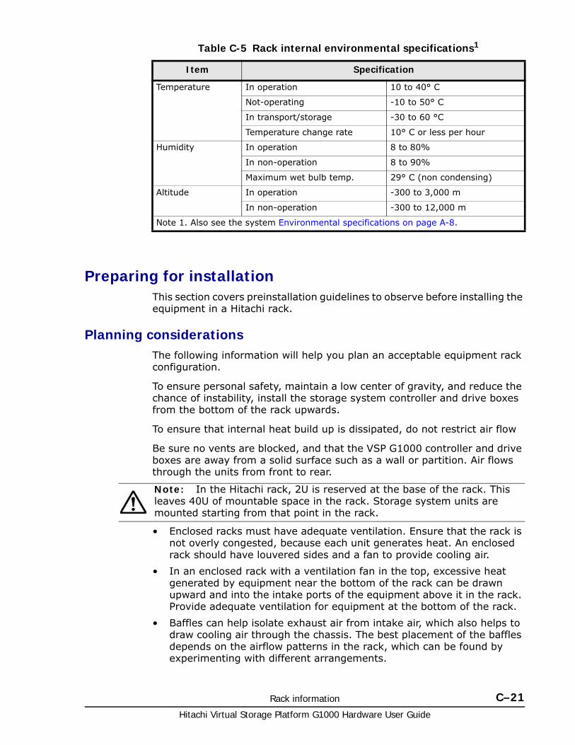
Rack information C–21Hitachi Virtual Storage Platform G1000 Hardware User Guide
Table C-5 Rack internal environmental specifications1
Preparing for installationThis section covers preinstallation guidelines to observe before installing the equipment in a Hitachi rack.
Planning considerationsThe following information will help you plan an acceptable equipment rack configuration.
To ensure personal safety, maintain a low center of gravity, and reduce the chance of instability, install the storage system controller and drive boxes from the bottom of the rack upwards.
To ensure that internal heat build up is dissipated, do not restrict air flow
Be sure no vents are blocked, and that the VSP G1000 controller and drive boxes are away from a solid surface such as a wall or partition. Air flows through the units from front to rear.
• Enclosed racks must have adequate ventilation. Ensure that the rack is not overly congested, because each unit generates heat. An enclosed rack should have louvered sides and a fan to provide cooling air.
• In an enclosed rack with a ventilation fan in the top, excessive heat generated by equipment near the bottom of the rack can be drawn upward and into the intake ports of the equipment above it in the rack. Provide adequate ventilation for equipment at the bottom of the rack.
• Baffles can help isolate exhaust air from intake air, which also helps to draw cooling air through the chassis. The best placement of the baffles depends on the airflow patterns in the rack, which can be found by experimenting with different arrangements.
Item Specification
Temperature In operation 10 to 40° C
Not-operating -10 to 50° C
In transport/storage -30 to 60 °C
Temperature change rate 10° C or less per hour
Humidity In operation 8 to 80%
In non-operation 8 to 90%
Maximum wet bulb temp. 29° C (non condensing)
Altitude In operation -300 to 3,000 m
In non-operation -300 to 12,000 m
Note 1. Also see the system Environmental specifications on page A-8.
Note: In the Hitachi rack, 2U is reserved at the base of the rack. This leaves 40U of mountable space in the rack. Storage system units are mounted starting from that point in the rack.
Hitachi Virtual Storage Platform G1000 Hardware User Guide
C–22 Rack information
• Consideration should be given to the floor ratings of the site where the rack and units will be installed. For information about the weight of an example storage controller and drive boxes, see Floor load ratings on page C-11.
Receiving the rack from the shipping carrierTo receive a fully integrated and configured Hitachi rack, consider the following:
• The dock door at the receiving site must accommodate the height and width of the rack.
• An appropriate freight elevator must be available for transporting the rack to upper and lower floors.
• Do not lay the rack down because the sheet metal may twist or distort.
• If the rack already has storage system components mounted in it, it may be heavy (250 lbs. to approximately 1000 lbs).
Tools required for installationThe following tools are required for securing products to the rack-mounting holes on a Hitachi rack:
• Adjustable wrench
• Cage nut tool
• Phillips screwdriver
All necessary screws, washers, cage nuts, and a cage nut too are suppled with the rack. When installing equipment, be sure to:
• Install the front anti-tip stabilizing plate to provide greater stability and safety. See Stabilizing the rack on page C-24 and Installing side stabilizer plates on page C-26. Figure C-15 Hitachi Universal Rack with Side Stabilizer Plates Installed on page C-27 shows an how to install the stabilizer plates.
• Mount heavier storage equipment such as the controller chassis at the bottom of the rack first. Then install equipment in the upper half of the rack.
Checking the hardwareIf the rack is ordered empty, it should come with all components. If additional features or options were ordered, or if the rack was ordered with Hitachi Data Systems products pre-installed, verify that all items have been received.
CastersThe casters enable movement of the rack across short distances in order to position it for final installation. As soon as the rack is in its final position for installation, adjust the leveling feet so that the full weight of the rack is supported by them.
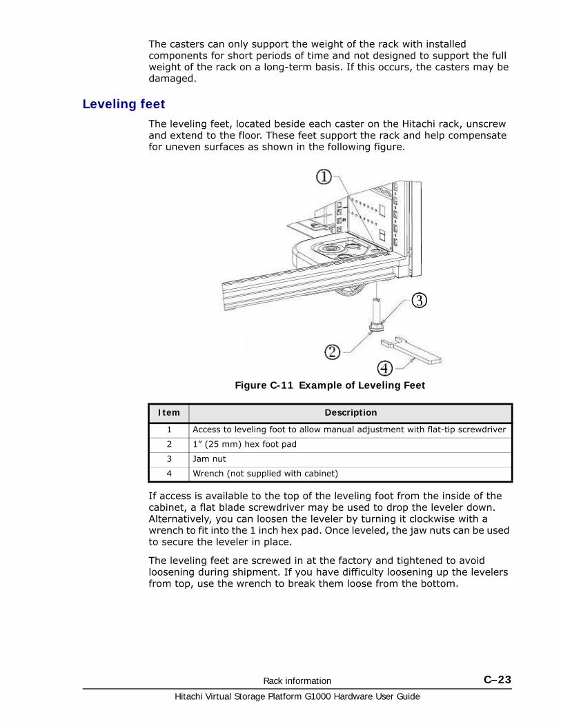
Rack information C–23Hitachi Virtual Storage Platform G1000 Hardware User Guide
The casters can only support the weight of the rack with installed components for short periods of time and not designed to support the full weight of the rack on a long-term basis. If this occurs, the casters may be damaged.
Leveling feetThe leveling feet, located beside each caster on the Hitachi rack, unscrew and extend to the floor. These feet support the rack and help compensate for uneven surfaces as shown in the following figure.
If access is available to the top of the leveling foot from the inside of the cabinet, a flat blade screwdriver may be used to drop the leveler down. Alternatively, you can loosen the leveler by turning it clockwise with a wrench to fit into the 1 inch hex pad. Once leveled, the jaw nuts can be used to secure the leveler in place.
The leveling feet are screwed in at the factory and tightened to avoid loosening during shipment. If you have difficulty loosening up the levelers from top, use the wrench to break them loose from the bottom.
Figure C-11 Example of Leveling Feet
Item Description
1 Access to leveling foot to allow manual adjustment with flat-tip screwdriver
2 1” (25 mm) hex foot pad
3 Jam nut
4 Wrench (not supplied with cabinet)
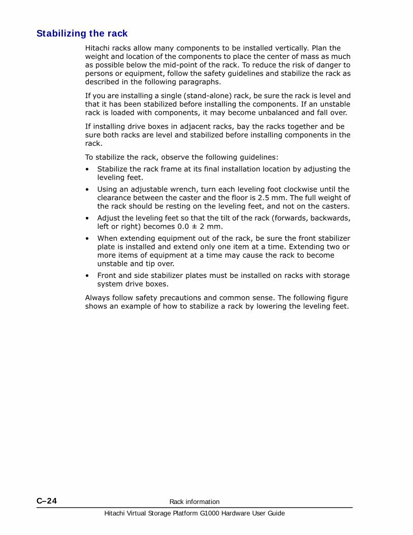
Hitachi Virtual Storage Platform G1000 Hardware User Guide
C–24 Rack information
Stabilizing the rackHitachi racks allow many components to be installed vertically. Plan the weight and location of the components to place the center of mass as much as possible below the mid-point of the rack. To reduce the risk of danger to persons or equipment, follow the safety guidelines and stabilize the rack as described in the following paragraphs.
If you are installing a single (stand-alone) rack, be sure the rack is level and that it has been stabilized before installing the components. If an unstable rack is loaded with components, it may become unbalanced and fall over.
If installing drive boxes in adjacent racks, bay the racks together and be sure both racks are level and stabilized before installing components in the rack.
To stabilize the rack, observe the following guidelines:
• Stabilize the rack frame at its final installation location by adjusting the leveling feet.
• Using an adjustable wrench, turn each leveling foot clockwise until the clearance between the caster and the floor is 2.5 mm. The full weight of the rack should be resting on the leveling feet, and not on the casters.
• Adjust the leveling feet so that the tilt of the rack (forwards, backwards, left or right) becomes 0.0 ± 2 mm.
• When extending equipment out of the rack, be sure the front stabilizer plate is installed and extend only one item at a time. Extending two or more items of equipment at a time may cause the rack to become unstable and tip over.
• Front and side stabilizer plates must be installed on racks with storage system drive boxes.
Always follow safety precautions and common sense. The following figure shows an example of how to stabilize a rack by lowering the leveling feet.
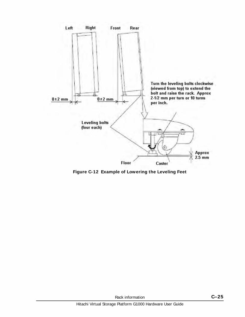
Rack information C–25Hitachi Virtual Storage Platform G1000 Hardware User Guide
Figure C-12 Example of Lowering the Leveling Feet
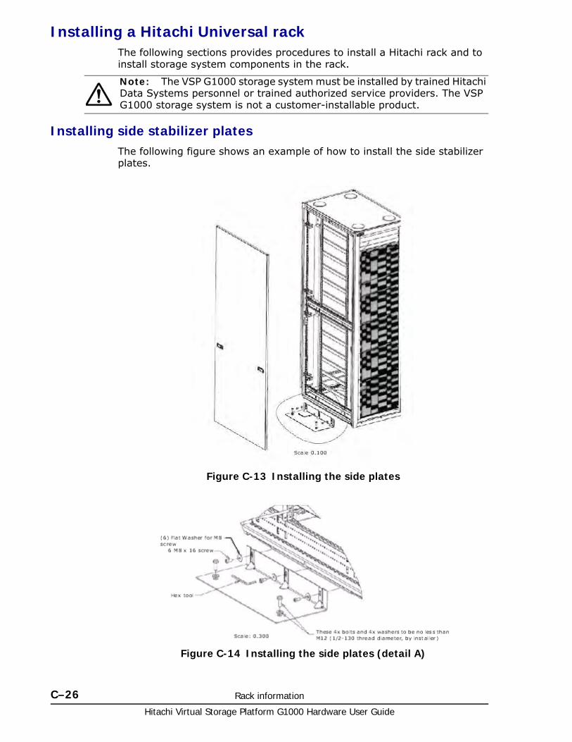
Hitachi Virtual Storage Platform G1000 Hardware User Guide
C–26 Rack information
Installing a Hitachi Universal rackThe following sections provides procedures to install a Hitachi rack and to install storage system components in the rack.
Installing side stabilizer platesThe following figure shows an example of how to install the side stabilizer plates.
Note: The VSP G1000 storage system must be installed by trained Hitachi Data Systems personnel or trained authorized service providers. The VSP G1000 storage system is not a customer-installable product.
Figure C-13 Installing the side plates
Figure C-14 Installing the side plates (detail A)
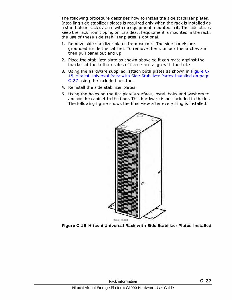
Rack information C–27Hitachi Virtual Storage Platform G1000 Hardware User Guide
The following procedure describes how to install the side stabilizer plates. Installing side stabilizer plates is required only when the rack is installed as a stand-alone rack system with no equipment mounted in it. The side plates keep the rack from tipping on its sides. If equipment is mounted in the rack, the use of these side stabilizer plates is optional.
1. Remove side stabilizer plates from cabinet. The side panels are grounded inside the cabinet. To remove them, unlock the latches and then pull panel out and up.
2. Place the stabilizer plate as shown above so it can mate against the bracket at the bottom sides of frame and align with the holes.
3. Using the hardware supplied, attach both plates as shown in Figure C-15 Hitachi Universal Rack with Side Stabilizer Plates Installed on page C-27 using the included hex tool.
4. Reinstall the side stabilizer plates.
5. Using the holes on the flat plate's surface, install bolts and washers to anchor the cabinet to the floor. This hardware is not included in the kit. The following figure shows the final view after everything is installed.
Figure C-15 Hitachi Universal Rack with Side Stabilizer Plates Installed
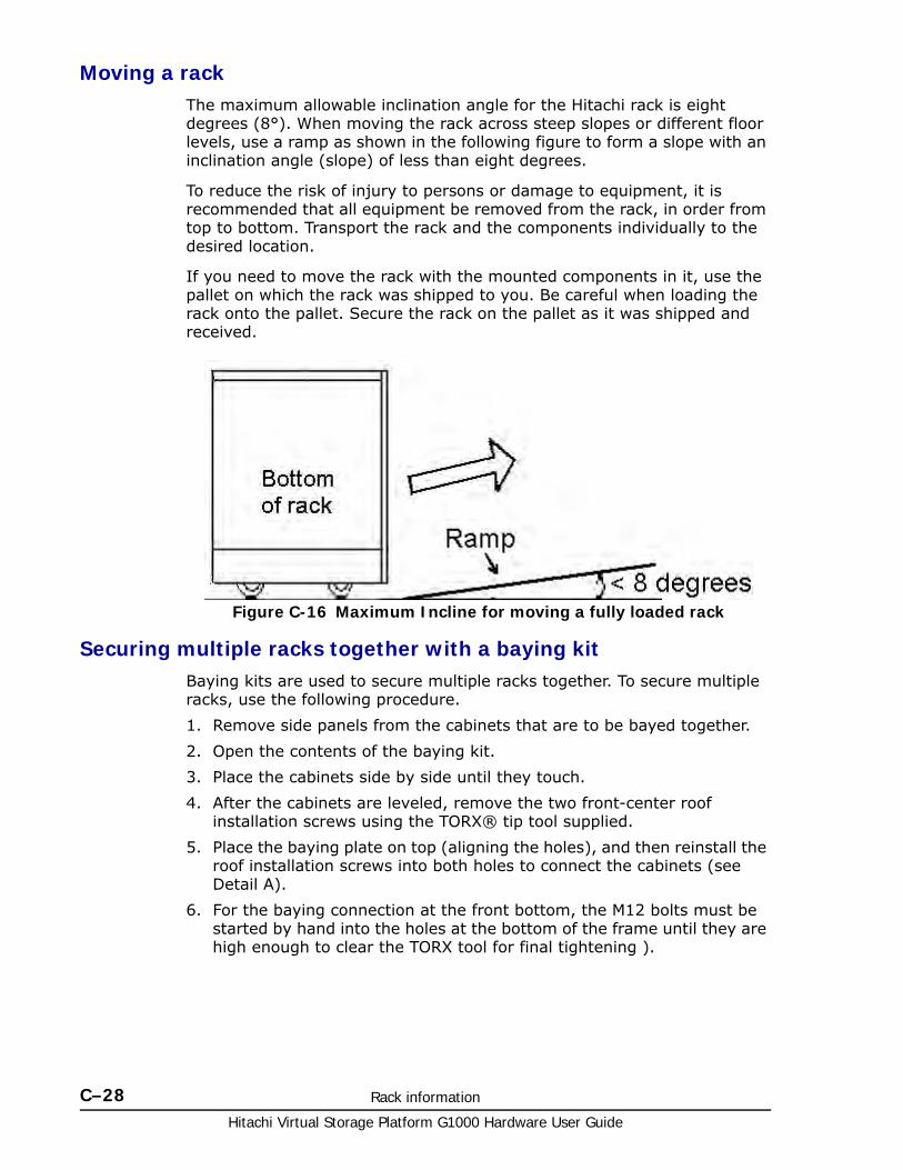
Hitachi Virtual Storage Platform G1000 Hardware User Guide
C–28 Rack information
Moving a rack The maximum allowable inclination angle for the Hitachi rack is eight degrees (8°). When moving the rack across steep slopes or different floor levels, use a ramp as shown in the following figure to form a slope with an inclination angle (slope) of less than eight degrees.
To reduce the risk of injury to persons or damage to equipment, it is recommended that all equipment be removed from the rack, in order from top to bottom. Transport the rack and the components individually to the desired location.
If you need to move the rack with the mounted components in it, use the pallet on which the rack was shipped to you. Be careful when loading the rack onto the pallet. Secure the rack on the pallet as it was shipped and received.
Securing multiple racks together with a baying kitBaying kits are used to secure multiple racks together. To secure multiple racks, use the following procedure.
1. Remove side panels from the cabinets that are to be bayed together.
2. Open the contents of the baying kit.
3. Place the cabinets side by side until they touch.
4. After the cabinets are leveled, remove the two front-center roof installation screws using the TORX® tip tool supplied.
5. Place the baying plate on top (aligning the holes), and then reinstall the roof installation screws into both holes to connect the cabinets (see Detail A).
6. For the baying connection at the front bottom, the M12 bolts must be started by hand into the holes at the bottom of the frame until they are high enough to clear the TORX tool for final tightening ).
Figure C-16 Maximum Incline for moving a fully loaded rack
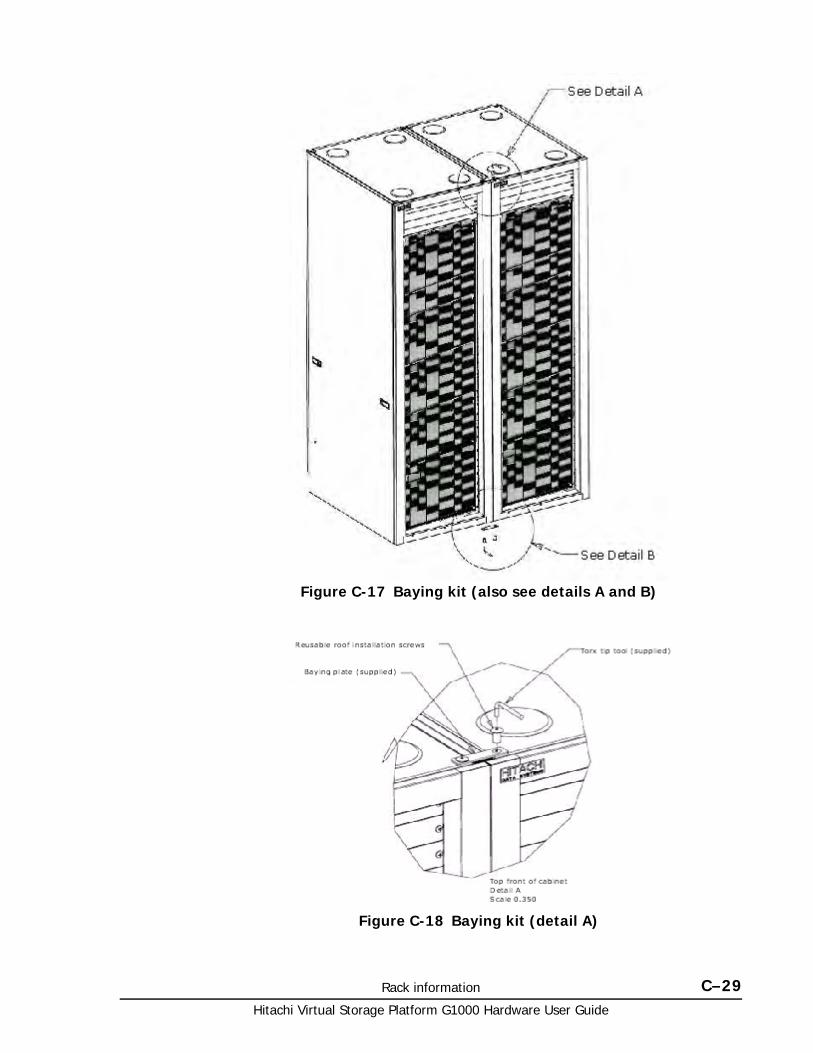
Rack information C–29Hitachi Virtual Storage Platform G1000 Hardware User Guide
Figure C-17 Baying kit (also see details A and B)
Figure C-18 Baying kit (detail A)
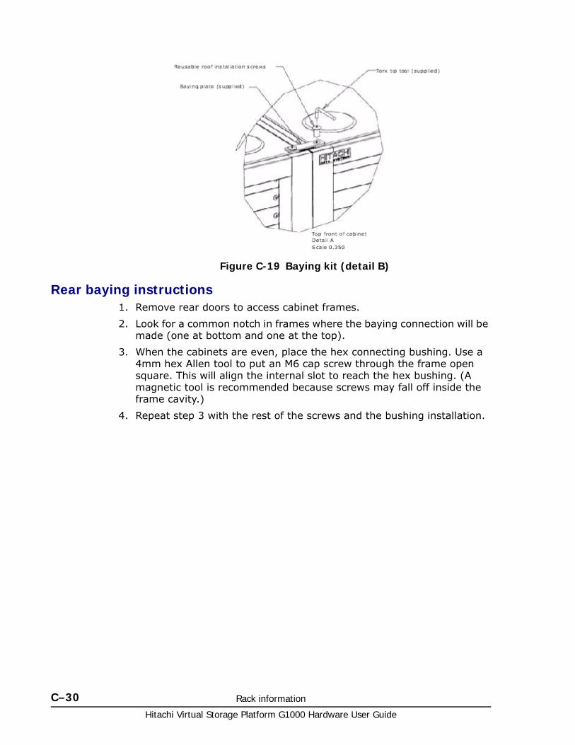
Hitachi Virtual Storage Platform G1000 Hardware User Guide
C–30 Rack information
Rear baying instructions1. Remove rear doors to access cabinet frames.
2. Look for a common notch in frames where the baying connection will be made (one at bottom and one at the top).
3. When the cabinets are even, place the hex connecting bushing. Use a 4mm hex Allen tool to put an M6 cap screw through the frame open square. This will align the internal slot to reach the hex bushing. (A magnetic tool is recommended because screws may fall off inside the frame cavity.)
4. Repeat step 3 with the rest of the screws and the bushing installation.
Figure C-19 Baying kit (detail B)
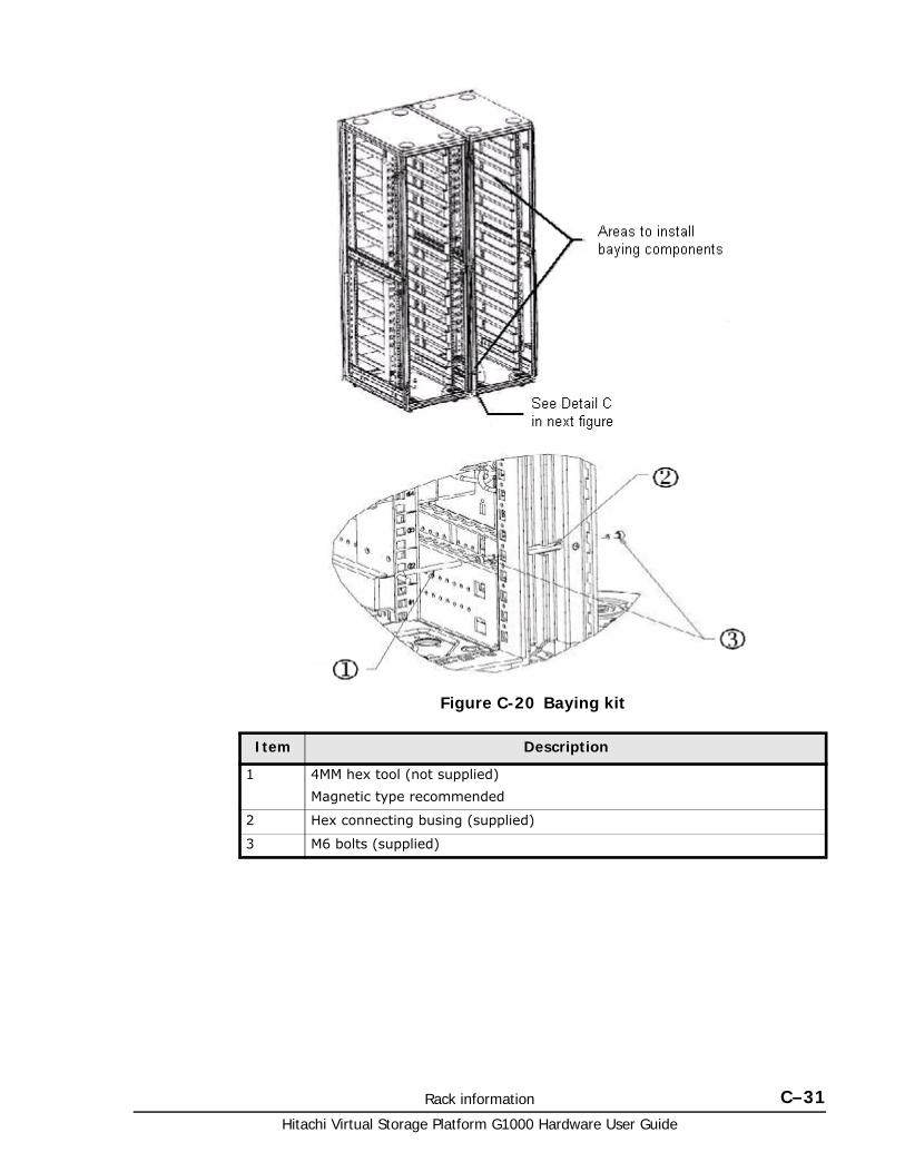
Rack information C–31Hitachi Virtual Storage Platform G1000 Hardware User Guide
Figure C-20 Baying kit
Item Description
1 4MM hex tool (not supplied)
Magnetic type recommended
2 Hex connecting busing (supplied)
3 M6 bolts (supplied)
Hitachi Virtual Storage Platform G1000 Hardware User Guide
C–32 Rack information
Opening and closing the side panelsThe side panels can be locked and unlocked with keys supplied with the rack. Once unlocked, press the release levers inward and pull the panel outwards and lift to remove. Reverse these procedures when reinstalling the side panels.
Installing equipment in a rackThis section describes how to install equipment in the Hitachi rack. The topics covered in this section are:
• Installation tasks on page C-32
• Installing cage nuts on page C-33
• Installing and uninstalling the anti-tip stabilizer plates on page C-33
• Installing blanking panels on page C-35
Before installing equipment, read the safety information on page C-19. When installing equipment, be sure to:
• Install the front anti-tip stabilizing plate when installing or removing equipment to provide greater stability and safety. See Stabilizing the rack on page C-24 and Installing side stabilizer plates. See Figure C-13 Installing the side plates on page C-26 and Figure C-14 Installing the side plates (detail A) on page C-26.
• Mount heavier equipment at the bottom of the rack prior to installing equipment in the upper half of the rack.
• Refer to the specific instructions included with the equipment you will mount.
Installation tasks
Most installations of equipment in the rack involve the following steps:
1. Determine location in the rack where the components will be mounted.
2. Remove side panels or rear door of rack (not necessary but may make installation easier).
3. Install rail kits or mounting hardware on which that equipment will rest in the rack.
4. Prepare the mounting hardware.
5. Insert the applicable cage nuts in the rack to which the rail kits will be secured.
6. Install the rail kits/mounting hardware into the rack.
7. Install the front anti-tip stabilizing plate to provide greater stability and safety. See Stabilizing the rack on page C-24 and Installing side stabilizer plates on page C-26.
Install the equipment into the rack as follows:
1. Determine what mounting holes will be used for securing the equipment to the rack, and install cage nuts at these locations.
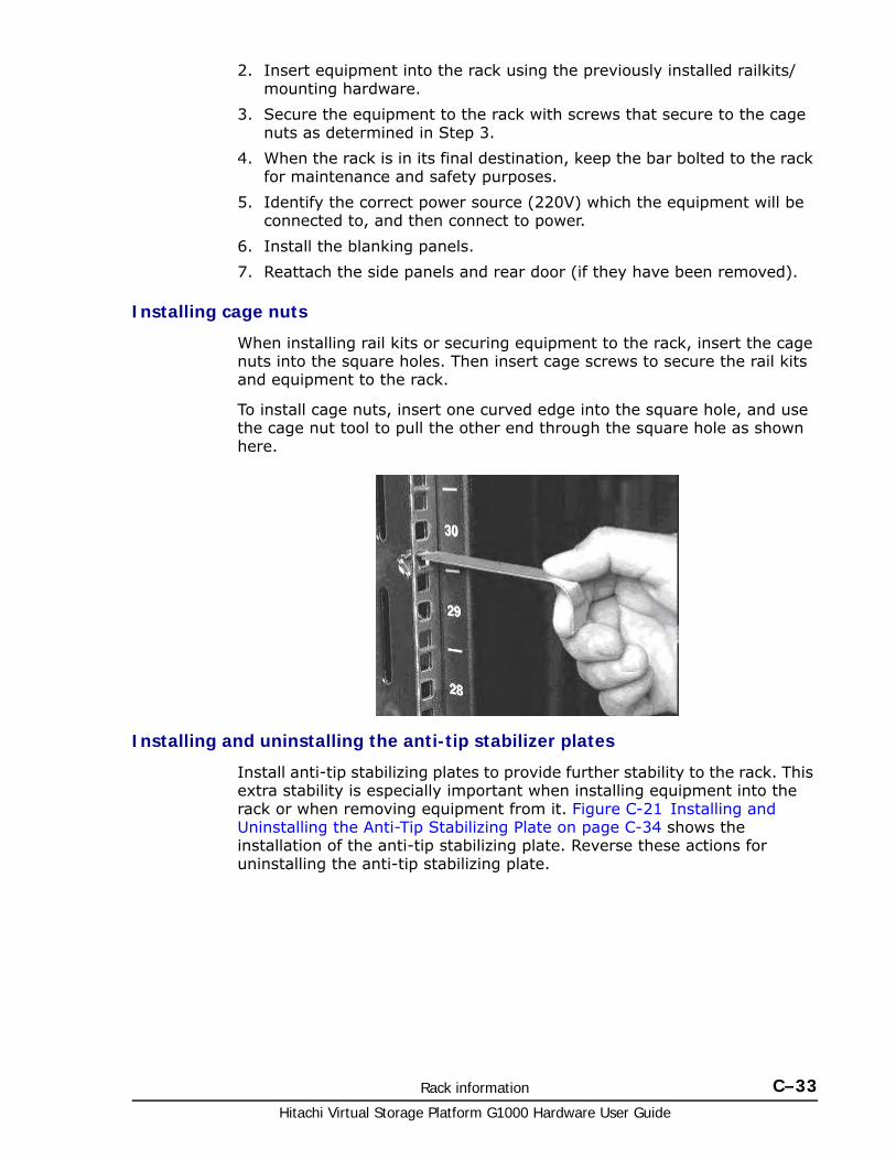
Rack information C–33Hitachi Virtual Storage Platform G1000 Hardware User Guide
2. Insert equipment into the rack using the previously installed railkits/mounting hardware.
3. Secure the equipment to the rack with screws that secure to the cage nuts as determined in Step 3.
4. When the rack is in its final destination, keep the bar bolted to the rack for maintenance and safety purposes.
5. Identify the correct power source (220V) which the equipment will be connected to, and then connect to power.
6. Install the blanking panels.
7. Reattach the side panels and rear door (if they have been removed).
Installing cage nuts
When installing rail kits or securing equipment to the rack, insert the cage nuts into the square holes. Then insert cage screws to secure the rail kits and equipment to the rack.
To install cage nuts, insert one curved edge into the square hole, and use the cage nut tool to pull the other end through the square hole as shown here.
Installing and uninstalling the anti-tip stabilizer plates
Install anti-tip stabilizing plates to provide further stability to the rack. This extra stability is especially important when installing equipment into the rack or when removing equipment from it. Figure C-21 Installing and Uninstalling the Anti-Tip Stabilizing Plate on page C-34 shows the installation of the anti-tip stabilizing plate. Reverse these actions for uninstalling the anti-tip stabilizing plate.
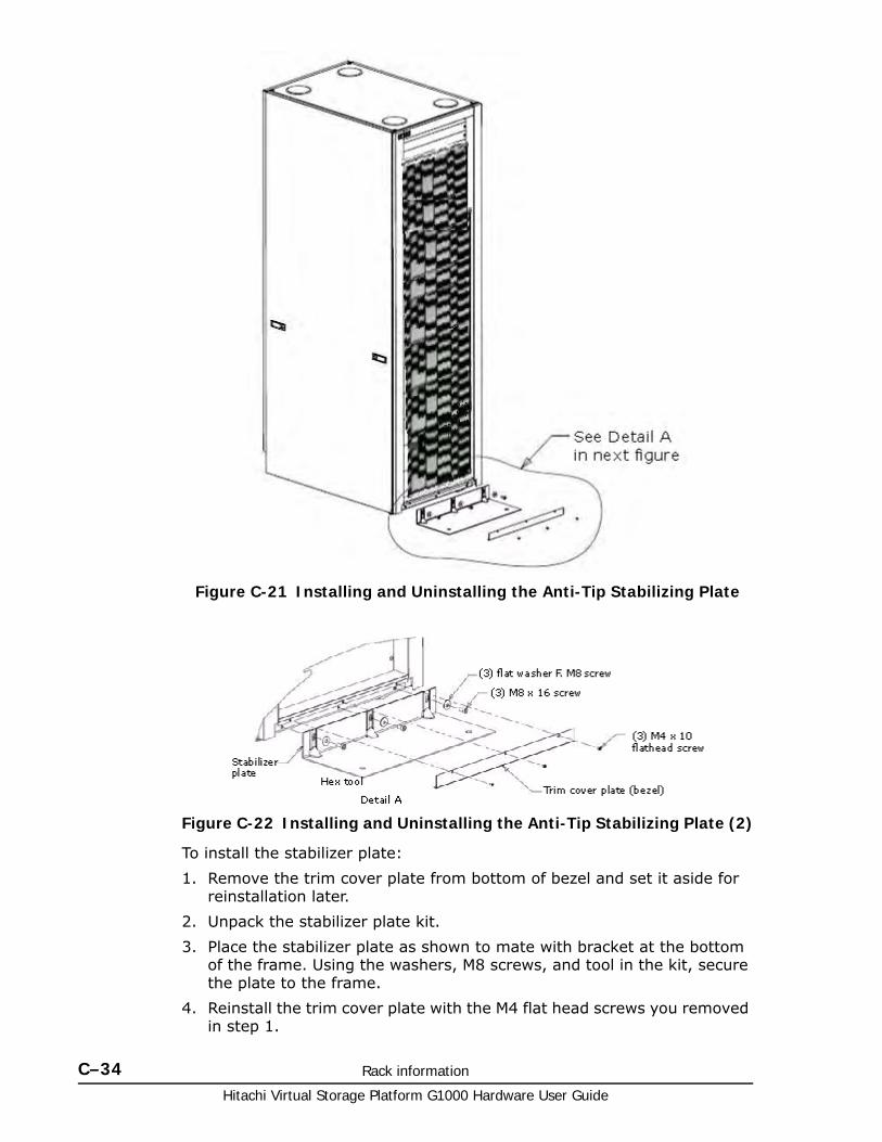
Hitachi Virtual Storage Platform G1000 Hardware User Guide
C–34 Rack information
To install the stabilizer plate:
1. Remove the trim cover plate from bottom of bezel and set it aside for reinstallation later.
2. Unpack the stabilizer plate kit.
3. Place the stabilizer plate as shown to mate with bracket at the bottom of the frame. Using the washers, M8 screws, and tool in the kit, secure the plate to the frame.
4. Reinstall the trim cover plate with the M4 flat head screws you removed in step 1.
Figure C-21 Installing and Uninstalling the Anti-Tip Stabilizing Plate
Figure C-22 Installing and Uninstalling the Anti-Tip Stabilizing Plate (2)
Rack information C–35Hitachi Virtual Storage Platform G1000 Hardware User Guide
Installing blanking panels
Blanking panels should be installed to cover any empty space at the front of the rack. This will ensure adequate airflow to the equipment in the rack if the rack is not completely filled.
When installing blanking panels, follow these steps:
1. Place the blanking panel on the rack as a template to determine which holes will require cage nuts.
2. Insert the cage nuts.
3. Secure the panels to the rack by screwing them onto the rack at the cage nut locations.
Post-installation considerationsThe following sections provide guidelines to consider after you install equipment in the Hitachi rack.
CastersThe casters facilitate movement of the rack across short distances in order to position it for final installation. As soon as the rack is in its final position for installation, make sure that the full weight of the rack is supported by the leveling feet.
The casters can only support the weight of the rack with installed components for short periods of time and not designed to support the full weight of the rack on a long-term basis. If this occurs, the casters may be damaged.
Inspection and cleaningFollow these guidelines when inspecting and cleaning the rack.
• If the equipment must be powered off, perform the power-off sequence described in Power On/Off procedures on page 5-1, before proceeding with maintenance.
• Do not work on the equipment or rack in a damp or wet environment.
• Do not obstruct access to the rack with parts or tools.
• If the rack has a door, before performing the work with the door open, take off metal watches or jewelry to prevent electric shock. If you wear metal-frame glasses, do not touch the equipment.
• Ensure that loose clothing, jewelry, or hair does not become tangled in moving components.
• Observe the safety notices and statements in this manual to make sure that high-voltage components are not touched during maintenance. Have another person with you when you work in high voltage areas, so that if there is a problem , he or she can turn off the power and call for help if needed.
Hitachi Virtual Storage Platform G1000 Hardware User Guide
C–36 Rack information
• After the power feed to the equipment is shut off, electricity remains in the equipment for a period of time. Do not touch any components other than those indicated in this chapter.
• The equipment can become extremely hot. Do not touch any parts other than those indicated in this chapter.
• When working with the door open, wear cotton gloves to prevent your hands from touching sharp objects.
D
System option modes D–1Hitachi Virtual Storage Platform G1000 Hardware User Guide
System option modes
This appendix lists and describes the public system option modes.
□ System option modes
Hitachi Virtual Storage Platform G1000 Hardware User Guide
D–2 System option modes
System option modesTo provide greater flexibility and enable the VSP G1000 to be tailored to unique customer operating requirements, additional operational parameters, or system option modes, are available. At installation, the modes are set to their default values, as shown in the following table. Be sure to discuss these settings with your Hitachi Data Systems team if you think changes should be made. The system option modes can only be changed by a Hitachi Data Systems representative.
The following tables provide information about system option modes and and SVP operations:
• Table D-1 System option modes on page D-2 lists the public system option mode information for VSP G1000. These can be used as needed.
• Table D-2 Mode 269: Device Manager - Storage Navigator Operations on page D-44 specifies the details for mode 269 for Device Manager - Storage Navigator operations.
• Table D-3 Mode 269: SVP Operations on page D-44 specifies the details of mode 269 for SVP operations.
The following tables were up to date at the time this manual was published. However, the system option mode information may change in firmware releases that may happen before the next release of this manual. Contact Hitachi Data Systems support for the latest information on the VSP G1000 system option modes.
The system option mode information includes:
• Mode: Specifies the system option mode number.
• Category: Indicates the functions to which the mode applies.
• Description: Describes the action or function that the mode provides.
• Default: Specifies the default setting (ON or OFF) for the mode.
• MCU/RCU: For remote functions, indicates whether the mode applies to the main control unit (MCU) and/or the remote control unit (RCU).
Table D-1 System option modes
Mode Category Description Default MCU/RCU
20 Public
(Optional)
R-VOL read only function. OFF MCU
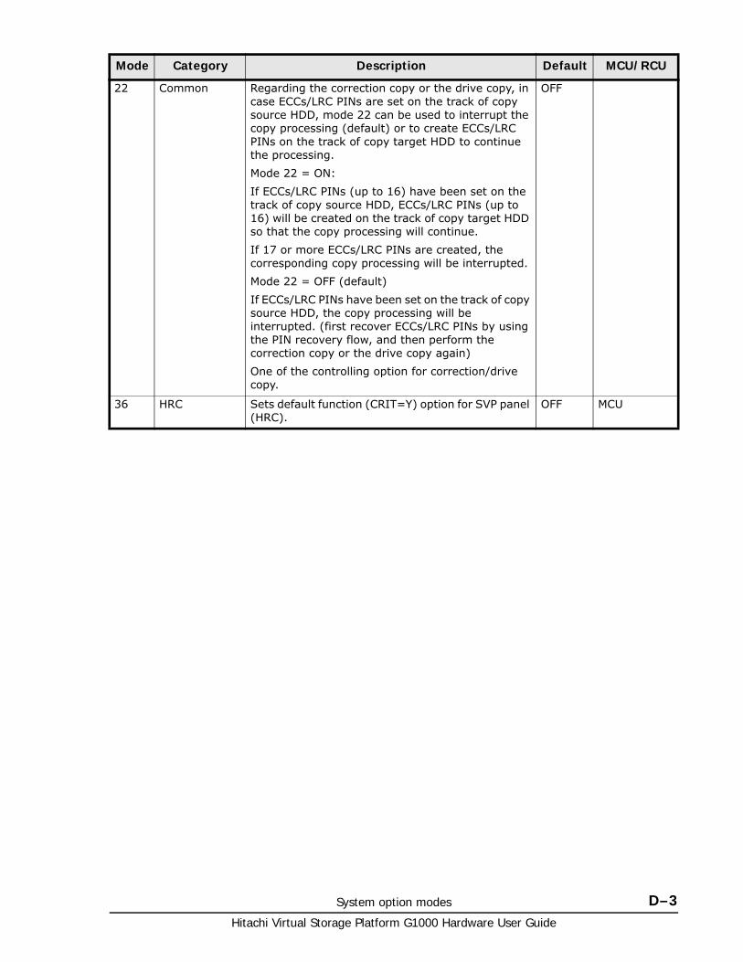
System option modes D–3Hitachi Virtual Storage Platform G1000 Hardware User Guide
22 Common Regarding the correction copy or the drive copy, in case ECCs/LRC PINs are set on the track of copy source HDD, mode 22 can be used to interrupt the copy processing (default) or to create ECCs/LRC PINs on the track of copy target HDD to continue the processing.
Mode 22 = ON:
If ECCs/LRC PINs (up to 16) have been set on the track of copy source HDD, ECCs/LRC PINs (up to 16) will be created on the track of copy target HDD so that the copy processing will continue.
If 17 or more ECCs/LRC PINs are created, the corresponding copy processing will be interrupted.
Mode 22 = OFF (default)
If ECCs/LRC PINs have been set on the track of copy source HDD, the copy processing will be interrupted. (first recover ECCs/LRC PINs by using the PIN recovery flow, and then perform the correction copy or the drive copy again)
One of the controlling option for correction/drive copy.
OFF
36 HRC Sets default function (CRIT=Y) option for SVP panel (HRC).
OFF MCU
Mode Category Description Default MCU/RCU
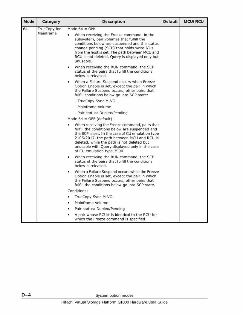
Hitachi Virtual Storage Platform G1000 Hardware User Guide
D–4 System option modes
64 TrueCopy for Mainframe
Mode 64 = ON:
• When receiving the Freeze command, in the subsystem, pair volumes that fulfill the conditions below are suspended and the status change pending (SCP) that holds write I/Os from the host is set. The path between MCU and RCU is not deleted. Query is displayed only but unusable.
• When receiving the RUN command, the SCP status of the pairs that fulfill the conditions below is released.
• When a Failure Suspend occurs when Freeze Option Enable is set, except the pair in which the Failure Suspend occurs, other pairs that fulfill conditions below go into SCP state:
- TrueCopy Sync M-VOL
- Mainframe Volume
- Pair status: Duplex/Pending
Mode 64 = OFF (default):
• When receiving the Freeze command, pairs that fulfill the conditions below are suspended and the SCP is set. In the case of CU emulation type 2105/2017, the path between MCU and RCU is deleted, while the path is not deleted but unusable with Query displayed only in the case of CU emulation type 3990.
• When receiving the RUN command, the SCP status of the pairs that fulfill the conditions below is released.
• When a Failure Suspend occurs while the Freeze Option Enable is set, except the pair in which the Failure Suspend occurs, other pairs that fulfill the conditions below go into SCP state.
Conditions:
• TrueCopy Sync M-VOL
• Mainframe Volume
• Pair status: Duplex/Pending
• A pair whose RCU# is identical to the RCU for which the Freeze command is specified.
Mode Category Description Default MCU/RCU
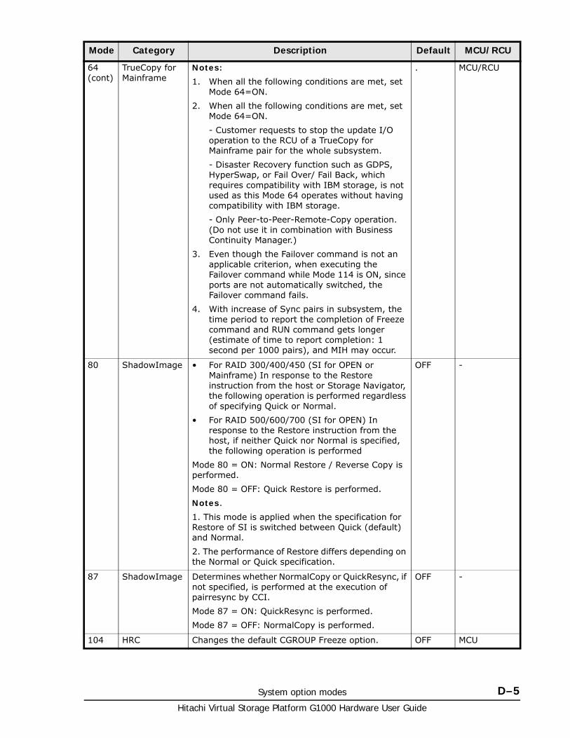
System option modes D–5Hitachi Virtual Storage Platform G1000 Hardware User Guide
64 (cont)
TrueCopy for Mainframe
Notes:
1. When all the following conditions are met, set Mode 64=ON.
2. When all the following conditions are met, set Mode 64=ON.
- Customer requests to stop the update I/O operation to the RCU of a TrueCopy for Mainframe pair for the whole subsystem.
- Disaster Recovery function such as GDPS, HyperSwap, or Fail Over/ Fail Back, which requires compatibility with IBM storage, is not used as this Mode 64 operates without having compatibility with IBM storage.
- Only Peer-to-Peer-Remote-Copy operation. (Do not use it in combination with Business Continuity Manager.)
3. Even though the Failover command is not an applicable criterion, when executing the Failover command while Mode 114 is ON, since ports are not automatically switched, the Failover command fails.
4. With increase of Sync pairs in subsystem, the time period to report the completion of Freeze command and RUN command gets longer (estimate of time to report completion: 1 second per 1000 pairs), and MIH may occur.
. MCU/RCU
80 ShadowImage • For RAID 300/400/450 (SI for OPEN or Mainframe) In response to the Restore instruction from the host or Storage Navigator, the following operation is performed regardless of specifying Quick or Normal.
• For RAID 500/600/700 (SI for OPEN) In response to the Restore instruction from the host, if neither Quick nor Normal is specified, the following operation is performed
Mode 80 = ON: Normal Restore / Reverse Copy is performed.
Mode 80 = OFF: Quick Restore is performed.
Notes.
1. This mode is applied when the specification for Restore of SI is switched between Quick (default) and Normal.
2. The performance of Restore differs depending on the Normal or Quick specification.
OFF -
87 ShadowImage Determines whether NormalCopy or QuickResync, if not specified, is performed at the execution of pairresync by CCI.
Mode 87 = ON: QuickResync is performed.
Mode 87 = OFF: NormalCopy is performed.
OFF -
104 HRC Changes the default CGROUP Freeze option. OFF MCU
Mode Category Description Default MCU/RCU
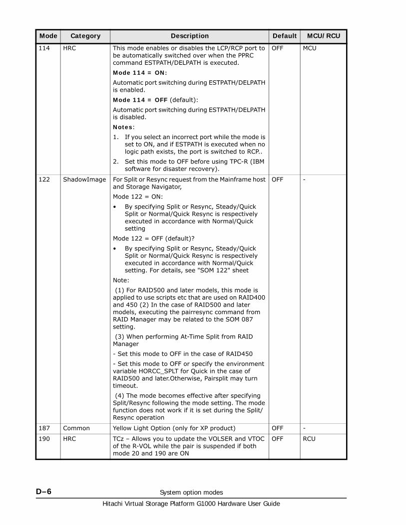
Hitachi Virtual Storage Platform G1000 Hardware User Guide
D–6 System option modes
114 HRC This mode enables or disables the LCP/RCP port to be automatically switched over when the PPRC command ESTPATH/DELPATH is executed.
Mode 114 = ON:
Automatic port switching during ESTPATH/DELPATH is enabled.
Mode 114 = OFF (default):
Automatic port switching during ESTPATH/DELPATH is disabled.
Notes:
1. If you select an incorrect port while the mode is set to ON, and if ESTPATH is executed when no logic path exists, the port is switched to RCP..
2. Set this mode to OFF before using TPC-R (IBM software for disaster recovery).
OFF MCU
122 ShadowImage For Split or Resync request from the Mainframe host and Storage Navigator,
Mode 122 = ON:
• By specifying Split or Resync, Steady/Quick Split or Normal/Quick Resync is respectively executed in accordance with Normal/Quick setting
Mode 122 = OFF (default)?
• By specifying Split or Resync, Steady/Quick Split or Normal/Quick Resync is respectively executed in accordance with Normal/Quick setting. For details, see "SOM 122" sheet
Note:
(1) For RAID500 and later models, this mode is applied to use scripts etc that are used on RAID400 and 450 (2) In the case of RAID500 and later models, executing the pairresync command from RAID Manager may be related to the SOM 087 setting.
(3) When performing At-Time Split from RAID Manager
- Set this mode to OFF in the case of RAID450
- Set this mode to OFF or specify the environment variable HORCC_SPLT for Quick in the case of RAID500 and later.Otherwise, Pairsplit may turn timeout.
(4) The mode becomes effective after specifying Split/Resync following the mode setting. The mode function does not work if it is set during the Split/Resync operation
OFF -
187 Common Yellow Light Option (only for XP product) OFF -
190 HRC TCz – Allows you to update the VOLSER and VTOC of the R-VOL while the pair is suspended if both mode 20 and 190 are ON
OFF RCU
Mode Category Description Default MCU/RCU
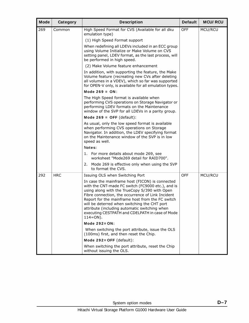
System option modes D–7Hitachi Virtual Storage Platform G1000 Hardware User Guide
269 Common High Speed Format for CVS (Available for all dku emulation type)
(1) High Speed Format support
When redefining all LDEVs included in an ECC group using Volume Initialize or Make Volume on CVS setting panel, LDEV format, as the last process, will be performed in high speed.
(2) Make Volume feature enhancement
In addition, with supporting the feature, the Make Volume feature (recreating new CVs after deleting all volumes in a VDEV), which so far was supported for OPEN-V only, is available for all emulation types.
Mode 269 = ON:
The High Speed format is available when performing CVS operations on Storage Navigator or performing LDEV formats on the Maintenance window of the SVP for all LDEVs in a parity group.
Mode 269 = OFF (default):
As usual, only the low speed format is available when performing CVS operations on Storage Navigator. In addition, the LDEV specifying format on the Maintenance window of the SVP is in low speed as well.
Notes:
1. For more details about mode 269, see worksheet "Mode269 detail for RAID700".
2. Mode 269 is effective only when using the SVP to format the CVS.
OFF MCU/RCU
292 HRC Issuing OLS when Switching Port
In case the mainframe host (FICON) is connected with the CNT-made FC switch (FC9000 etc.), and is using along with the TrueCopy S/390 with Open Fibre connection, the occurrence of Link Incident Report for the mainframe host from the FC switch will be deterred when switching the CHT port attribute (including automatic switching when executing CESTPATH and CDELPATH in case of Mode 114=ON).
Mode 292=ON:
When switching the port attribute, issue the OLS (100ms) first, and then reset the Chip.
Mode 292=OFF (default):
When switching the port attribute, reset the Chip without issuing the OLS.
OFF MCU/RCU
Mode Category Description Default MCU/RCU
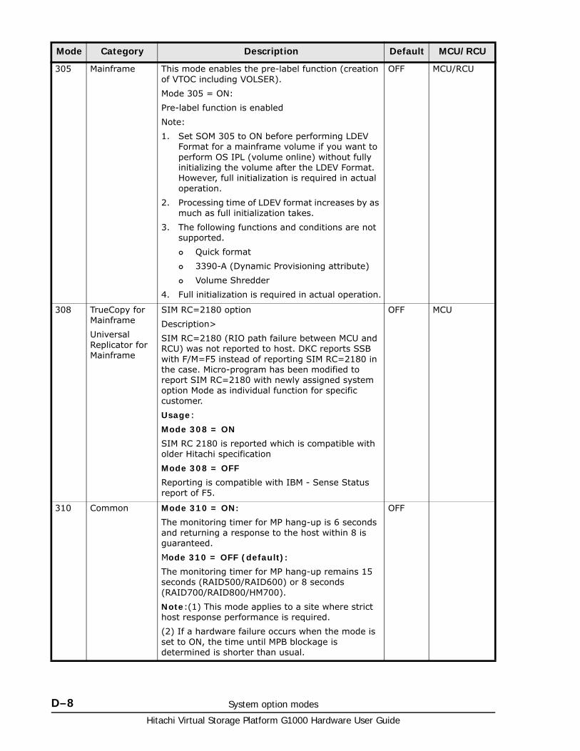
Hitachi Virtual Storage Platform G1000 Hardware User Guide
D–8 System option modes
305 Mainframe This mode enables the pre-label function (creation of VTOC including VOLSER).
Mode 305 = ON:
Pre-label function is enabled
Note:
1. Set SOM 305 to ON before performing LDEV Format for a mainframe volume if you want to perform OS IPL (volume online) without fully initializing the volume after the LDEV Format. However, full initialization is required in actual operation.
2. Processing time of LDEV format increases by as much as full initialization takes.
3. The following functions and conditions are not supported.
Quick format
3390-A (Dynamic Provisioning attribute)
Volume Shredder
4. Full initialization is required in actual operation.
OFF MCU/RCU
308 TrueCopy for Mainframe
Universal Replicator for Mainframe
SIM RC=2180 option
Description>
SIM RC=2180 (RIO path failure between MCU and RCU) was not reported to host. DKC reports SSB with F/M=F5 instead of reporting SIM RC=2180 in the case. Micro-program has been modified to report SIM RC=2180 with newly assigned system option Mode as individual function for specific customer.
Usage:
Mode 308 = ON
SIM RC 2180 is reported which is compatible with older Hitachi specification
Mode 308 = OFF
Reporting is compatible with IBM - Sense Status report of F5.
OFF MCU
310 Common Mode 310 = ON:
The monitoring timer for MP hang-up is 6 seconds and returning a response to the host within 8 is guaranteed.
Mode 310 = OFF (default):
The monitoring timer for MP hang-up remains 15 seconds (RAID500/RAID600) or 8 seconds (RAID700/RAID800/HM700).
Note:(1) This mode applies to a site where strict host response performance is required.
(2) If a hardware failure occurs when the mode is set to ON, the time until MPB blockage is determined is shorter than usual.
OFF
Mode Category Description Default MCU/RCU

System option modes D–9Hitachi Virtual Storage Platform G1000 Hardware User Guide
448 Universal Replicator
Universal Replicator for Mainframe
Mode 448 = ON: (Enabled)
If the SVP detects a blocked path, the SVP assumes that an error occurred, and then immediately splits (suspends) the mirror.
Mode 448 = OFF: (Disabled)
If the SVP detects a blocked path and the path does not recover within the specified period of time, the SVP assumes that an error occurred, and then splits (suspends) the mirror.
Note:
The mode 448 setting takes effect only when mode 449 is set to OFF.
OFF
449 Universal Replicator
Universal Replicator for Mainframe
Detecting and monitoring path blockade between MCU and RCU of Universal Replicator/Universal Replicator for z/OS
<Functionality>
- Mode 449 on: Detecting and monitoring of path blockade will NOT be performed.
- Mode 449 off (default *) : Detecting and monitoring of the path blockade will be performed.
* Newly shipped DKC will have Mode 449 = ON as default.
Note: The mode status will not be changed by the microcode exchange.
Mode Category Description Default MCU/RCU
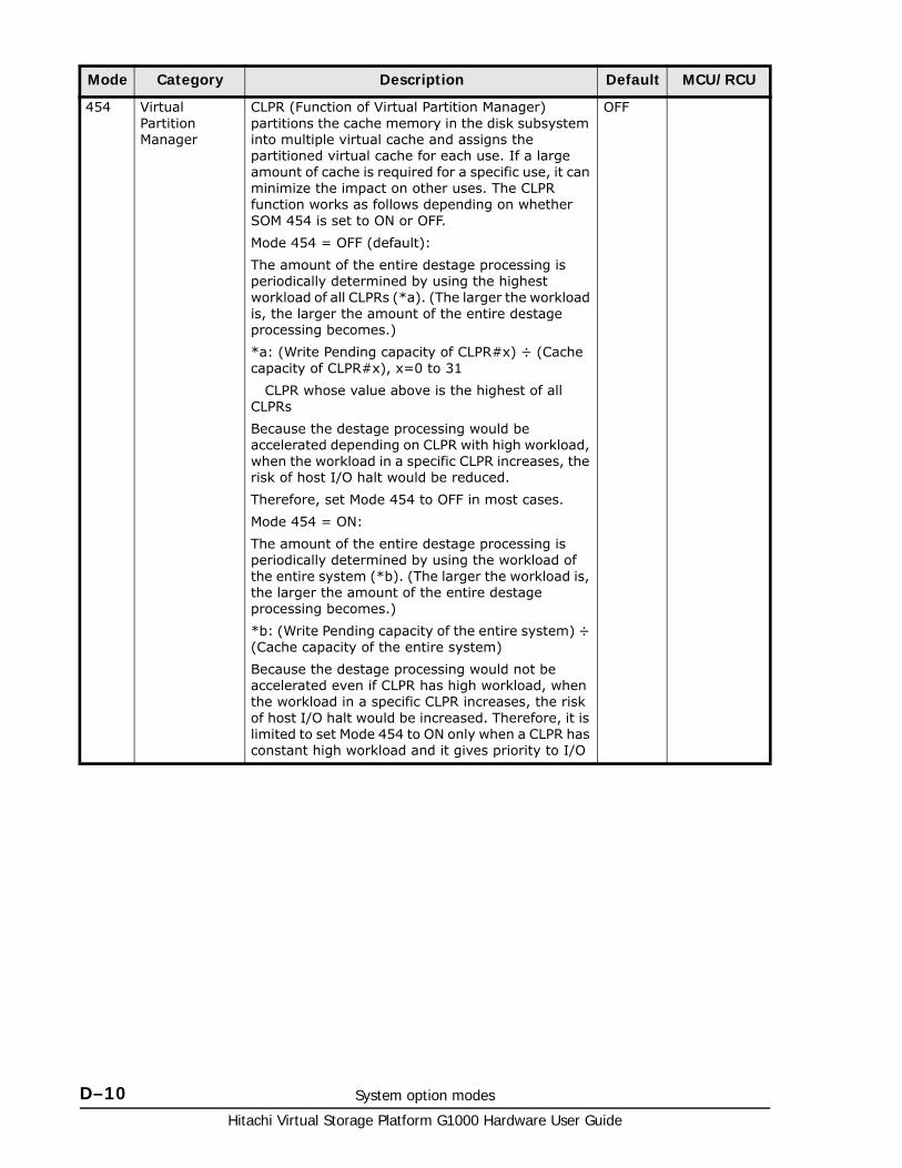
Hitachi Virtual Storage Platform G1000 Hardware User Guide
D–10 System option modes
454 Virtual Partition Manager
CLPR (Function of Virtual Partition Manager) partitions the cache memory in the disk subsystem into multiple virtual cache and assigns the partitioned virtual cache for each use. If a large amount of cache is required for a specific use, it can minimize the impact on other uses. The CLPR function works as follows depending on whether SOM 454 is set to ON or OFF.
Mode 454 = OFF (default):
The amount of the entire destage processing is periodically determined by using the highest workload of all CLPRs (*a). (The larger the workload is, the larger the amount of the entire destage processing becomes.)
*a: (Write Pending capacity of CLPR#x) ÷ (Cache capacity of CLPR#x), x=0 to 31
CLPR whose value above is the highest of all CLPRs
Because the destage processing would be accelerated depending on CLPR with high workload, when the workload in a specific CLPR increases, the risk of host I/O halt would be reduced.
Therefore, set Mode 454 to OFF in most cases.
Mode 454 = ON:
The amount of the entire destage processing is periodically determined by using the workload of the entire system (*b). (The larger the workload is, the larger the amount of the entire destage processing becomes.)
*b: (Write Pending capacity of the entire system) ÷ (Cache capacity of the entire system)
Because the destage processing would not be accelerated even if CLPR has high workload, when the workload in a specific CLPR increases, the risk of host I/O halt would be increased. Therefore, it is limited to set Mode 454 to ON only when a CLPR has constant high workload and it gives priority to I/O
OFF
Mode Category Description Default MCU/RCU
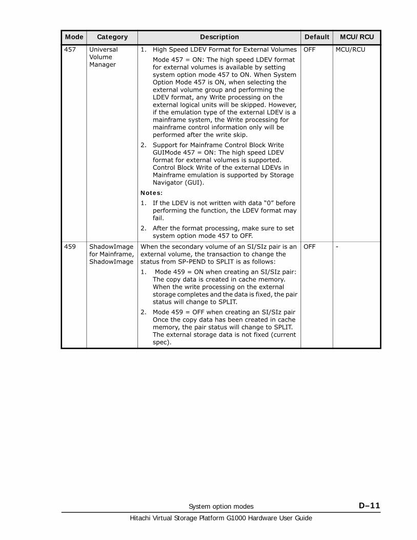
System option modes D–11Hitachi Virtual Storage Platform G1000 Hardware User Guide
457 Universal Volume Manager
1. High Speed LDEV Format for External Volumes
Mode 457 = ON: The high speed LDEV format for external volumes is available by setting system option mode 457 to ON. When System Option Mode 457 is ON, when selecting the external volume group and performing the LDEV format, any Write processing on the external logical units will be skipped. However, if the emulation type of the external LDEV is a mainframe system, the Write processing for mainframe control information only will be performed after the write skip.
2. Support for Mainframe Control Block Write GUIMode 457 = ON: The high speed LDEV format for external volumes is supported. Control Block Write of the external LDEVs in Mainframe emulation is supported by Storage Navigator (GUI).
Notes:
1. If the LDEV is not written with data “0” before performing the function, the LDEV format may fail.
2. After the format processing, make sure to set system option mode 457 to OFF.
OFF MCU/RCU
459 ShadowImage for Mainframe, ShadowImage
When the secondary volume of an SI/SIz pair is an external volume, the transaction to change the status from SP-PEND to SPLIT is as follows:
1. Mode 459 = ON when creating an SI/SIz pair: The copy data is created in cache memory. When the write processing on the external storage completes and the data is fixed, the pair status will change to SPLIT.
2. Mode 459 = OFF when creating an SI/SIz pair Once the copy data has been created in cache memory, the pair status will change to SPLIT. The external storage data is not fixed (current spec).
OFF -
Mode Category Description Default MCU/RCU
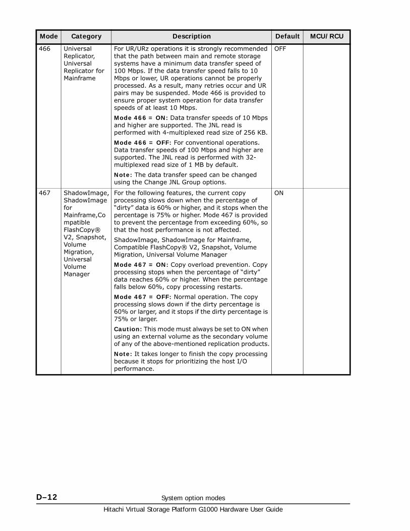
Hitachi Virtual Storage Platform G1000 Hardware User Guide
D–12 System option modes
466 Universal Replicator, Universal Replicator for Mainframe
For UR/URz operations it is strongly recommended that the path between main and remote storage systems have a minimum data transfer speed of 100 Mbps. If the data transfer speed falls to 10 Mbps or lower, UR operations cannot be properly processed. As a result, many retries occur and UR pairs may be suspended. Mode 466 is provided to ensure proper system operation for data transfer speeds of at least 10 Mbps.
Mode 466 = ON: Data transfer speeds of 10 Mbps and higher are supported. The JNL read is performed with 4-multiplexed read size of 256 KB.
Mode 466 = OFF: For conventional operations. Data transfer speeds of 100 Mbps and higher are supported. The JNL read is performed with 32-multiplexed read size of 1 MB by default.
Note: The data transfer speed can be changed using the Change JNL Group options.
OFF
467 ShadowImage, ShadowImage for Mainframe,Compatible FlashCopy® V2, Snapshot, Volume Migration, Universal Volume Manager
For the following features, the current copy processing slows down when the percentage of “dirty” data is 60% or higher, and it stops when the percentage is 75% or higher. Mode 467 is provided to prevent the percentage from exceeding 60%, so that the host performance is not affected.
ShadowImage, ShadowImage for Mainframe, Compatible FlashCopy® V2, Snapshot, Volume Migration, Universal Volume Manager
Mode 467 = ON: Copy overload prevention. Copy processing stops when the percentage of “dirty” data reaches 60% or higher. When the percentage falls below 60%, copy processing restarts.
Mode 467 = OFF: Normal operation. The copy processing slows down if the dirty percentage is 60% or larger, and it stops if the dirty percentage is 75% or larger.
Caution: This mode must always be set to ON when using an external volume as the secondary volume of any of the above-mentioned replication products.
Note: It takes longer to finish the copy processing because it stops for prioritizing the host I/O performance.
ON
Mode Category Description Default MCU/RCU
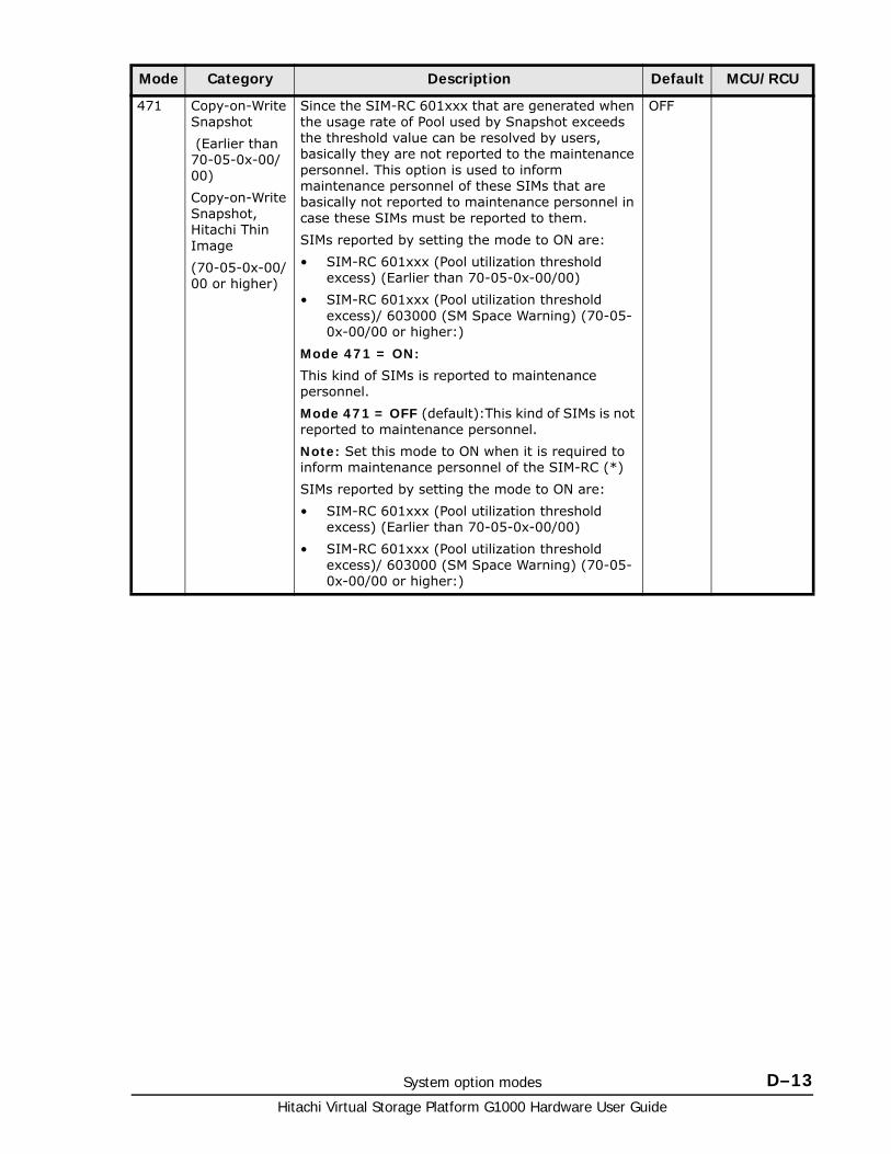
System option modes D–13Hitachi Virtual Storage Platform G1000 Hardware User Guide
471 Copy-on-Write Snapshot
(Earlier than 70-05-0x-00/00)
Copy-on-Write Snapshot, Hitachi Thin Image
(70-05-0x-00/00 or higher)
Since the SIM-RC 601xxx that are generated when the usage rate of Pool used by Snapshot exceeds the threshold value can be resolved by users, basically they are not reported to the maintenance personnel. This option is used to inform maintenance personnel of these SIMs that are basically not reported to maintenance personnel in case these SIMs must be reported to them.
SIMs reported by setting the mode to ON are:
• SIM-RC 601xxx (Pool utilization threshold excess) (Earlier than 70-05-0x-00/00)
• SIM-RC 601xxx (Pool utilization threshold excess)/ 603000 (SM Space Warning) (70-05-0x-00/00 or higher:)
Mode 471 = ON:
This kind of SIMs is reported to maintenance personnel.
Mode 471 = OFF (default):This kind of SIMs is not reported to maintenance personnel.
Note: Set this mode to ON when it is required to inform maintenance personnel of the SIM-RC (*)
SIMs reported by setting the mode to ON are:
• SIM-RC 601xxx (Pool utilization threshold excess) (Earlier than 70-05-0x-00/00)
• SIM-RC 601xxx (Pool utilization threshold excess)/ 603000 (SM Space Warning) (70-05-0x-00/00 or higher:)
OFF
Mode Category Description Default MCU/RCU
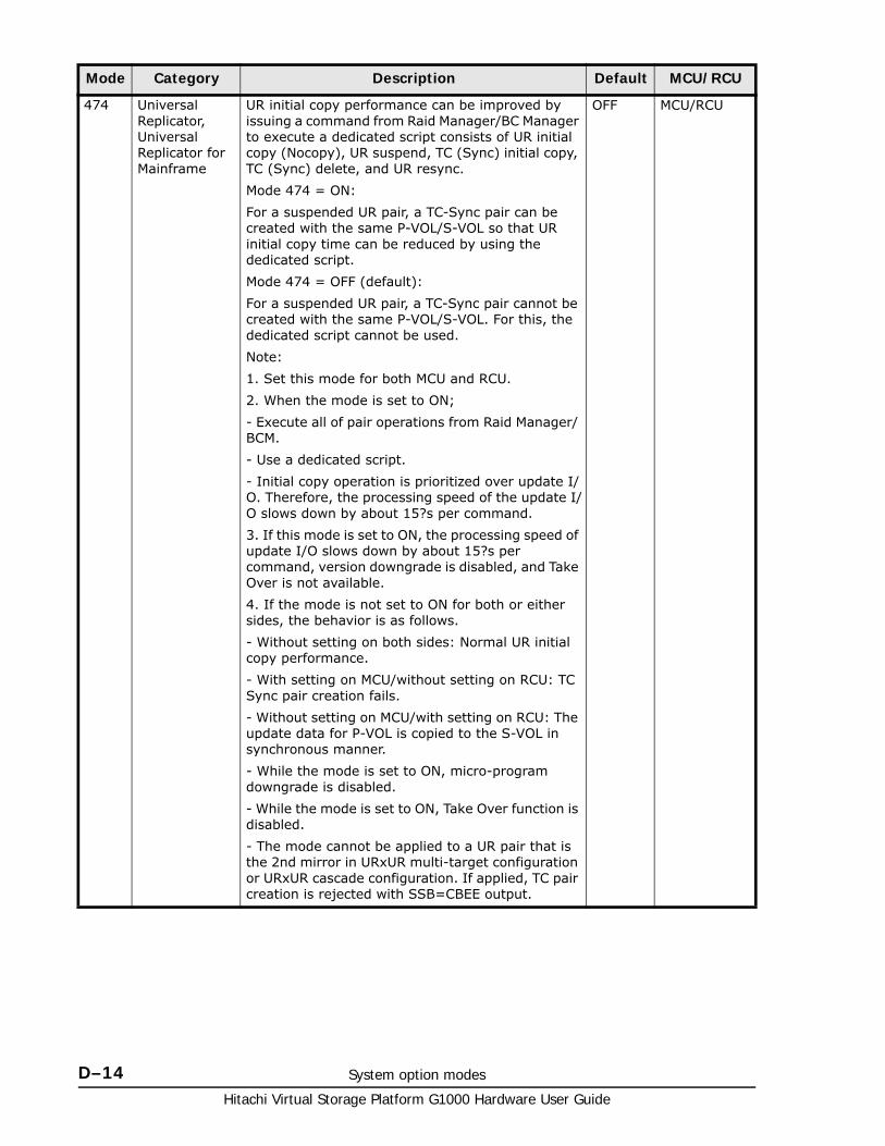
Hitachi Virtual Storage Platform G1000 Hardware User Guide
D–14 System option modes
474 Universal Replicator, Universal Replicator for Mainframe
UR initial copy performance can be improved by issuing a command from Raid Manager/BC Manager to execute a dedicated script consists of UR initial copy (Nocopy), UR suspend, TC (Sync) initial copy, TC (Sync) delete, and UR resync.
Mode 474 = ON:
For a suspended UR pair, a TC-Sync pair can be created with the same P-VOL/S-VOL so that UR initial copy time can be reduced by using the dedicated script.
Mode 474 = OFF (default):
For a suspended UR pair, a TC-Sync pair cannot be created with the same P-VOL/S-VOL. For this, the dedicated script cannot be used.
Note:
1. Set this mode for both MCU and RCU.
2. When the mode is set to ON;
- Execute all of pair operations from Raid Manager/ BCM.
- Use a dedicated script.
- Initial copy operation is prioritized over update I/O. Therefore, the processing speed of the update I/O slows down by about 15?s per command.
3. If this mode is set to ON, the processing speed of update I/O slows down by about 15?s per command, version downgrade is disabled, and Take Over is not available.
4. If the mode is not set to ON for both or either sides, the behavior is as follows.
- Without setting on both sides: Normal UR initial copy performance.
- With setting on MCU/without setting on RCU: TC Sync pair creation fails.
- Without setting on MCU/with setting on RCU: The update data for P-VOL is copied to the S-VOL in synchronous manner.
- While the mode is set to ON, micro-program downgrade is disabled.
- While the mode is set to ON, Take Over function is disabled.
- The mode cannot be applied to a UR pair that is the 2nd mirror in URxUR multi-target configuration or URxUR cascade configuration. If applied, TC pair creation is rejected with SSB=CBEE output.
OFF MCU/RCU
Mode Category Description Default MCU/RCU
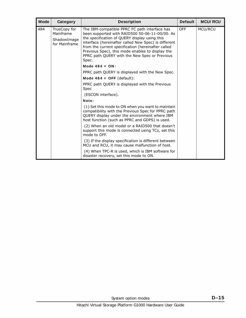
System option modes D–15Hitachi Virtual Storage Platform G1000 Hardware User Guide
484 TrueCopy for Mainframe
ShadowImage for Mainframe
The IBM-compatible PPRC FC path interface has been supported with RAID500 50-06-11-00/00. As the specification of QUERY display using this interface (hereinafter called New Spec) is different from the current specification (hereinafter called Previous Spec), this mode enables to display the PPRC path QUERY with the New Spec or Previous Spec.
Mode 484 = ON:
PPRC path QUERY is displayed with the New Spec.
Mode 484 = OFF (default):
PPRC path QUERY is displayed with the Previous Spec
(ESCON interface).
Note:
(1) Set this mode to ON when you want to maintain compatibility with the Previous Spec for PPRC path QUERY display under the environment where IBM host function (such as PPRC and GDPS) is used.
(2) When an old model or a RAID500 that doesn’t support this mode is connected using TCz, set this mode to OFF.
(3) If the display specification is different between MCU and RCU, it may cause malfunction of host.
(4) When TPC-R is used, which is IBM software for disaster recovery, set this mode to ON.
OFF MCU/RCU
Mode Category Description Default MCU/RCU
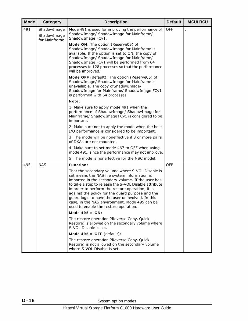
Hitachi Virtual Storage Platform G1000 Hardware User Guide
D–16 System option modes
491 ShadowImage
ShadowImage for Mainframe
Mode 491 is used for improving the performance of ShadowImage/ ShadowImage for Mainframe/ ShadowImage FCv1.
Mode ON: The option (Reserve05) of ShadowImage/ ShadowImage for Mainframe is available. If the option is set to ON, the copy of ShadowImage/ ShadowImage for Mainframe/ ShadowImage FCv1 will be performed from 64 processes to 128 processes so that the performance will be improved.
Mode OFF (default): The option (Reserve05) of ShadowImage/ ShadowImage for Mainframe is unavailable. The copy ofShadowImage/ ShadowImage for Mainframe/ ShadowImage FCv1 is performed with 64 processes.
Note:
1. Make sure to apply mode 491 when the performance of ShadowImage/ ShadowImage for Mainframe/ ShadowImage FCv1 is considered to be important.
2. Make sure not to apply the mode when the host I/O performance is considered to be important.
3. The mode will be noneffective if 3 or more pairs of DKAs are not mounted.
4. Make sure to set mode 467 to OFF when using mode 491, since the performance may not improve.
5. The mode is noneffective for the NSC model.
OFF .
495 NAS Function:
That the secondary volume where S-VOL Disable is set means the NAS file system information is imported in the secondary volume. If the user has to take a step to release the S-VOL Disable attribute in order to perform the restore operation, it is against the policy for the guard purpose and the guard logic to have the user uninvolved. In this case, in the NAS environment, Mode 495 can be used to enable the restore operation.
Mode 495 = ON:
The restore operation ?Reverse Copy, Quick Restore) is allowed on the secondary volume where S-VOL Disable is set.
Mode 495 = OFF (default):
The restore operation ?Reverse Copy, Quick Restore) is not allowed on the secondary volume where S-VOL Disable is set.
OFF
Mode Category Description Default MCU/RCU
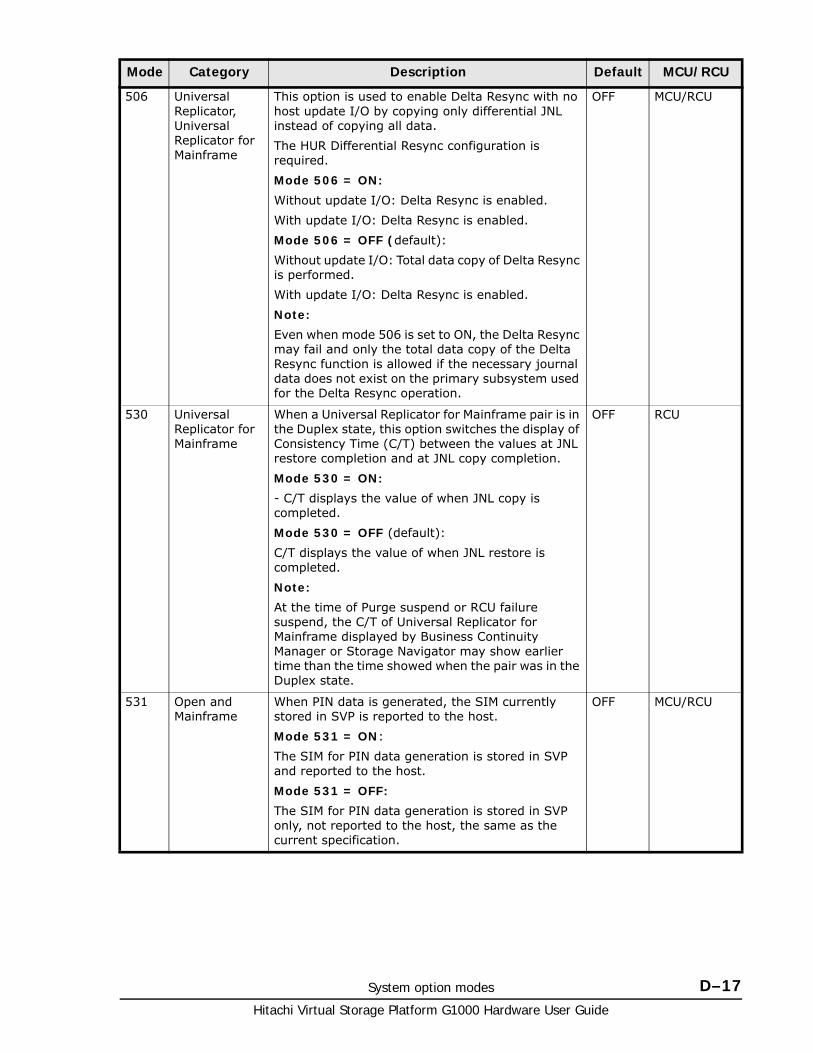
System option modes D–17Hitachi Virtual Storage Platform G1000 Hardware User Guide
506 Universal Replicator, Universal Replicator for Mainframe
This option is used to enable Delta Resync with no host update I/O by copying only differential JNL instead of copying all data.
The HUR Differential Resync configuration is required.
Mode 506 = ON:
Without update I/O: Delta Resync is enabled.
With update I/O: Delta Resync is enabled.
Mode 506 = OFF (default):
Without update I/O: Total data copy of Delta Resync is performed.
With update I/O: Delta Resync is enabled.
Note:
Even when mode 506 is set to ON, the Delta Resync may fail and only the total data copy of the Delta Resync function is allowed if the necessary journal data does not exist on the primary subsystem used for the Delta Resync operation.
OFF MCU/RCU
530 Universal Replicator for Mainframe
When a Universal Replicator for Mainframe pair is in the Duplex state, this option switches the display of Consistency Time (C/T) between the values at JNL restore completion and at JNL copy completion.
Mode 530 = ON:
- C/T displays the value of when JNL copy is completed.
Mode 530 = OFF (default):
C/T displays the value of when JNL restore is completed.
Note:
At the time of Purge suspend or RCU failure suspend, the C/T of Universal Replicator for Mainframe displayed by Business Continuity Manager or Storage Navigator may show earlier time than the time showed when the pair was in the Duplex state.
OFF RCU
531 Open and Mainframe
When PIN data is generated, the SIM currently stored in SVP is reported to the host.
Mode 531 = ON:
The SIM for PIN data generation is stored in SVP and reported to the host.
Mode 531 = OFF:
The SIM for PIN data generation is stored in SVP only, not reported to the host, the same as the current specification.
OFF MCU/RCU
Mode Category Description Default MCU/RCU
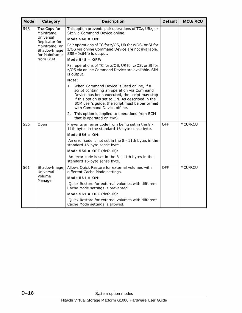
Hitachi Virtual Storage Platform G1000 Hardware User Guide
D–18 System option modes
548 TrueCopy for Mainframe, Universal Replicator for Mainframe, or ShadowImage for Mainframe from BCM
This option prevents pair operations of TCz, URz, or SIz via Command Device online.
Mode 548 = ON:
Pair operations of TC for z/OS, UR for z/OS, or SI for z/OS via online Command Device are not available. SSB=0x64fb is output.
Mode 548 = OFF:
Pair operations of TC for z/OS, UR for z/OS, or SI for z/OS via online Command Device are available. SIM is output.
Note:
1. When Command Device is used online, if a script containing an operation via Command Device has been executed, the script may stop if this option is set to ON. As described in the BCM user’s guide, the script must be performed with Command Device offline.
2. This option is applied to operations from BCM that is operated on MVS.
556 Open Prevents an error code from being set in the 8 - 11th bytes in the standard 16-byte sense byte.
Mode 556 = ON:
An error code is not set in the 8 - 11th bytes in the standard 16-byte sense byte.
Mode 556 = OFF (default):
An error code is set in the 8 - 11th bytes in the standard 16-byte sense byte.
OFF MCU/RCU
561 ShadowImage, Universal Volume Manager
Allows Quick Restore for external volumes with different Cache Mode settings.
Mode 561 = ON:
Quick Restore for external volumes with different Cache Mode settings is prevented.
Mode 561 = OFF (default):
Quick Restore for external volumes with different Cache Mode settings is allowed.
OFF MCU/RCU
Mode Category Description Default MCU/RCU
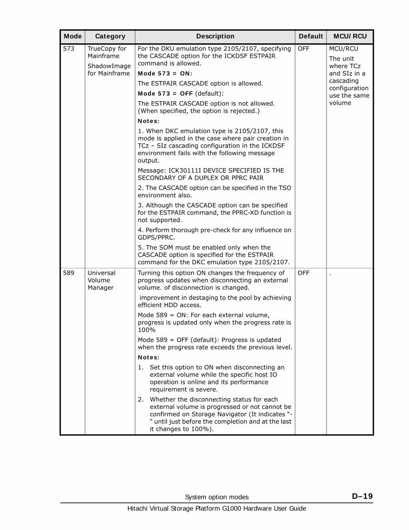
System option modes D–19Hitachi Virtual Storage Platform G1000 Hardware User Guide
573 TrueCopy for Mainframe
ShadowImage for Mainframe
For the DKU emulation type 2105/2107, specifying the CASCADE option for the ICKDSF ESTPAIR command is allowed.
Mode 573 = ON:
The ESTPAIR CASCADE option is allowed.
Mode 573 = OFF (default):
The ESTPAIR CASCADE option is not allowed. (When specified, the option is rejected.)
Notes:
1. When DKC emulation type is 2105/2107, this mode is applied in the case where pair creation in TCz – SIz cascading configuration in the ICKDSF environment fails with the following message output.
Message: ICK30111I DEVICE SPECIFIED IS THE SECONDARY OF A DUPLEX OR PPRC PAIR
2. The CASCADE option can be specified in the TSO environment also.
3. Although the CASCADE option can be specified for the ESTPAIR command, the PPRC-XD function is not supported.
4. Perform thorough pre-check for any influence on GDPS/PPRC.
5. The SOM must be enabled only when the CASCADE option is specified for the ESTPAIR command for the DKC emulation type 2105/2107.
OFF MCU/RCU
The unit where TCz and SIz in a cascading configuration use the same volume
589 Universal Volume Manager
Turning this option ON changes the frequency of progress updates when disconnecting an external volume. of disconnection is changed.
improvement in destaging to the pool by achieving efficient HDD access.
Mode 589 = ON: For each external volume, progress is updated only when the progress rate is 100%
Mode 589 = OFF (default): Progress is updated when the progress rate exceeds the previous level.
Notes:
1. Set this option to ON when disconnecting an external volume while the specific host IO operation is online and its performance requirement is severe.
2. Whether the disconnecting status for each external volume is progressed or not cannot be confirmed on Storage Navigator (It indicates “-“ until just before the completion and at the last it changes to 100%).
OFF .
Mode Category Description Default MCU/RCU
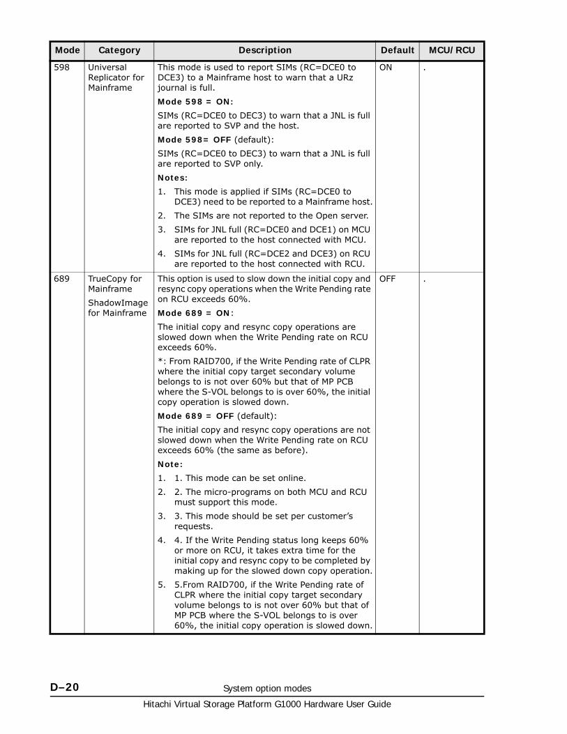
Hitachi Virtual Storage Platform G1000 Hardware User Guide
D–20 System option modes
598 Universal Replicator for Mainframe
This mode is used to report SIMs (RC=DCE0 to DCE3) to a Mainframe host to warn that a URz journal is full.
Mode 598 = ON:
SIMs (RC=DCE0 to DEC3) to warn that a JNL is full are reported to SVP and the host.
Mode 598= OFF (default):
SIMs (RC=DCE0 to DEC3) to warn that a JNL is full are reported to SVP only.
Notes:
1. This mode is applied if SIMs (RC=DCE0 to DCE3) need to be reported to a Mainframe host.
2. The SIMs are not reported to the Open server.
3. SIMs for JNL full (RC=DCE0 and DCE1) on MCU are reported to the host connected with MCU.
4. SIMs for JNL full (RC=DCE2 and DCE3) on RCU are reported to the host connected with RCU.
ON .
689 TrueCopy for Mainframe
ShadowImage for Mainframe
This option is used to slow down the initial copy and resync copy operations when the Write Pending rate on RCU exceeds 60%.
Mode 689 = ON:
The initial copy and resync copy operations are slowed down when the Write Pending rate on RCU exceeds 60%.
*: From RAID700, if the Write Pending rate of CLPR where the initial copy target secondary volume belongs to is not over 60% but that of MP PCB where the S-VOL belongs to is over 60%, the initial copy operation is slowed down.
Mode 689 = OFF (default):
The initial copy and resync copy operations are not slowed down when the Write Pending rate on RCU exceeds 60% (the same as before).
Note:
1. 1. This mode can be set online.
2. 2. The micro-programs on both MCU and RCU must support this mode.
3. 3. This mode should be set per customer’s requests.
4. 4. If the Write Pending status long keeps 60% or more on RCU, it takes extra time for the initial copy and resync copy to be completed by making up for the slowed down copy operation.
5. 5.From RAID700, if the Write Pending rate of CLPR where the initial copy target secondary volume belongs to is not over 60% but that of MP PCB where the S-VOL belongs to is over 60%, the initial copy operation is slowed down.
OFF .
Mode Category Description Default MCU/RCU
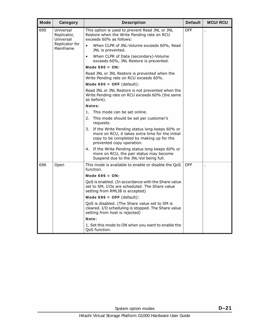
System option modes D–21Hitachi Virtual Storage Platform G1000 Hardware User Guide
690 Universal Replicator, Universal Replicator for Mainframe
This option is used to prevent Read JNL or JNL Restore when the Write Pending rate on RCU exceeds 60% as follows:
• When CLPR of JNL-Volume exceeds 60%, Read JNL is prevented.
• When CLPR of Data (secondary)-Volume exceeds 60%, JNL Restore is prevented.
Mode 690 = ON:
Read JNL or JNL Restore is prevented when the Write Pending rate on RCU exceeds 60%.
Mode 690 = OFF (default):
Read JNL or JNL Restore is not prevented when the Write Pending rate on RCU exceeds 60% (the same as before).
Notes:
1. This mode can be set online.
2. This mode should be set per customer’s requests.
3. If the Write Pending status long keeps 60% or more on RCU, it takes extra time for the initial copy to be completed by making up for the prevented copy operation.
4. If the Write Pending status long keeps 60% or more on RCU, the pair status may become Suspend due to the JNL-Vol being full.
OFF .
696 Open This mode is available to enable or disable the QoS function.
Mode 696 = ON:
QoS is enabled. (In accordance with the Share value set to SM, I/Os are scheduled. The Share value setting from RMLIB is accepted)
Mode 696 = OFF (default):
QoS is disabled. (The Share value set to SM is cleared. I/O scheduling is stopped. The Share value setting from host is rejected)
Note:
1. Set this mode to ON when you want to enable the QoS function.
OFF .
Mode Category Description Default MCU/RCU
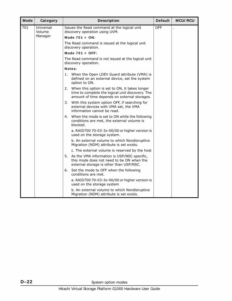
Hitachi Virtual Storage Platform G1000 Hardware User Guide
D–22 System option modes
701 Universal Volume Manager
Issues the Read command at the logical unit discovery operation using UVM.
Mode 701 = ON:
The Read command is issued at the logical unit discovery operation.
Mode 701 = OFF:
The Read command is not issued at the logical unit discovery operation.
Notes:
1. When the Open LDEV Guard attribute (VMA) is defined on an external device, set the system option to ON.
2. When this option is set to ON, it takes longer time to complete the logical unit discovery. The amount of time depends on external storages.
3. With this system option OFF, if searching for external devices with VMA set, the VMA information cannot be read.
4. When the mode is set to ON while the following conditions are met, the external volume is blocked.
a. RAID700 70-03-3x-00/00 or higher version is used on the storage system.
b. An external volume to which Nondisruptive Migration (NDM) attribute is set exists.
c. The external volume is reserved by the host
5. As the VMA information is USP/NSC specific, this mode does not need to be ON when the external storage is other than USP/NSC.
6. Set the mode to OFF when the following conditions are met.
a. RAID700 70-03-3x-00/00 or higher version is used on the storage system
b. An external volume to which Nondisruptive Migration (NDM) attribute is set exists.
OFF .
Mode Category Description Default MCU/RCU
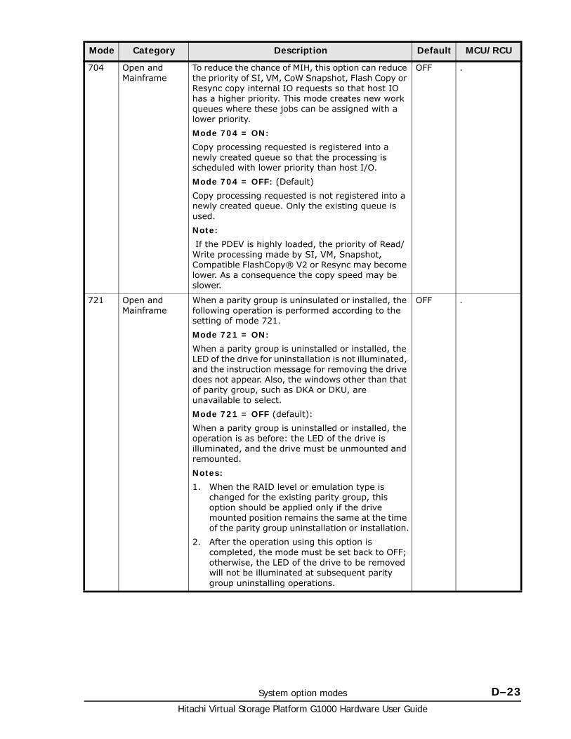
System option modes D–23Hitachi Virtual Storage Platform G1000 Hardware User Guide
704 Open and Mainframe
To reduce the chance of MIH, this option can reduce the priority of SI, VM, CoW Snapshot, Flash Copy or Resync copy internal IO requests so that host IO has a higher priority. This mode creates new work queues where these jobs can be assigned with a lower priority.
Mode 704 = ON:
Copy processing requested is registered into a newly created queue so that the processing is scheduled with lower priority than host I/O.
Mode 704 = OFF: (Default)
Copy processing requested is not registered into a newly created queue. Only the existing queue is used.
Note:
If the PDEV is highly loaded, the priority of Read/Write processing made by SI, VM, Snapshot, Compatible FlashCopy® V2 or Resync may become lower. As a consequence the copy speed may be slower.
OFF .
721 Open and Mainframe
When a parity group is uninsulated or installed, the following operation is performed according to the setting of mode 721.
Mode 721 = ON:
When a parity group is uninstalled or installed, the LED of the drive for uninstallation is not illuminated, and the instruction message for removing the drive does not appear. Also, the windows other than that of parity group, such as DKA or DKU, are unavailable to select.
Mode 721 = OFF (default):
When a parity group is uninstalled or installed, the operation is as before: the LED of the drive is illuminated, and the drive must be unmounted and remounted.
Notes:
1. When the RAID level or emulation type is changed for the existing parity group, this option should be applied only if the drive mounted position remains the same at the time of the parity group uninstallation or installation.
2. After the operation using this option is completed, the mode must be set back to OFF; otherwise, the LED of the drive to be removed will not be illuminated at subsequent parity group uninstalling operations.
OFF .
Mode Category Description Default MCU/RCU
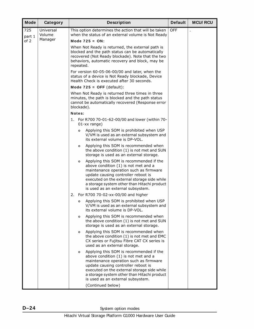
Hitachi Virtual Storage Platform G1000 Hardware User Guide
D–24 System option modes
725
part 1 of 2
Universal Volume Manager
This option determines the action that will be taken when the status of an external volume is Not Ready
Mode 725 = ON:
When Not Ready is returned, the external path is blocked and the path status can be automatically recovered (Not Ready blockade). Note that the two behaviors, automatic recovery and block, may be repeated.
For version 60-05-06-00/00 and later, when the status of a device is Not Ready blockade, Device Health Check is executed after 30 seconds.
Mode 725 = OFF (default):
When Not Ready is returned three times in three minutes, the path is blocked and the path status cannot be automatically recovered (Response error blockade).
Notes:
1. For R700 70-01-62-00/00 and lower (within 70-01-xx range)
Applying this SOM is prohibited when USP V/VM is used as an external subsystem and its external volume is DP-VOL.
Applying this SOM is recommended when the above condition (1) is not met and SUN storage is used as an external storage.
Applying this SOM is recommended if the above condition (1) is not met and a maintenance operation such as firmware update causing controller reboot is executed on the external storage side while a storage system other than Hitachi product is used as an external subsystem.
2. For R700 70-02-xx-00/00 and higher
Applying this SOM is prohibited when USP V/VM is used as an external subsystem and its external volume is DP-VOL.
Applying this SOM is recommended when the above condition (1) is not met and SUN storage is used as an external storage.
Applying this SOM is recommended when the above condition (1) is not met and EMC CX series or Fujitsu Fibre CAT CX series is used as an external storage.
Applying this SOM is recommended if the above condition (1) is not met and a maintenance operation such as firmware update causing controller reboot is executed on the external storage side while a storage system other than Hitachi product is used as an external subsystem.
(Continued below)
OFF .
Mode Category Description Default MCU/RCU
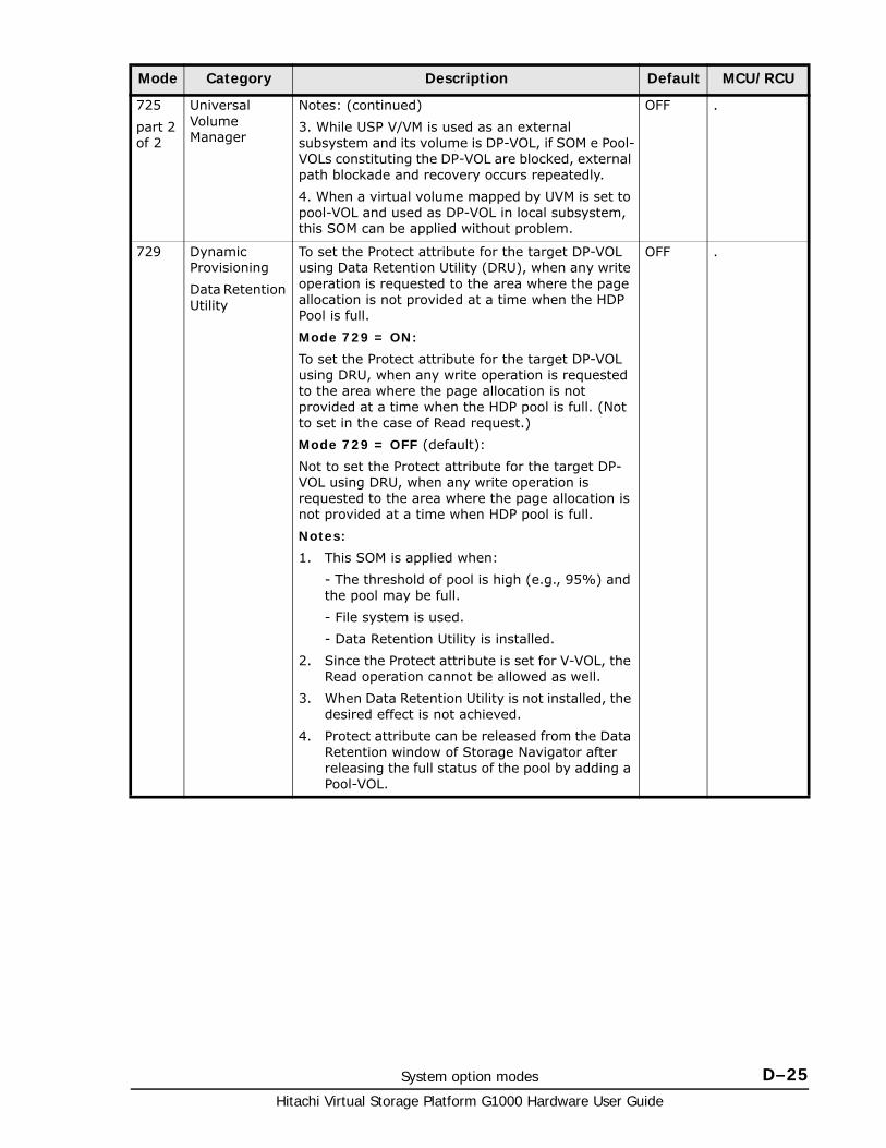
System option modes D–25Hitachi Virtual Storage Platform G1000 Hardware User Guide
725
part 2 of 2
Universal Volume Manager
Notes: (continued)
3. While USP V/VM is used as an external subsystem and its volume is DP-VOL, if SOM e Pool-VOLs constituting the DP-VOL are blocked, external path blockade and recovery occurs repeatedly.
4. When a virtual volume mapped by UVM is set to pool-VOL and used as DP-VOL in local subsystem, this SOM can be applied without problem.
OFF .
729 Dynamic Provisioning
Data Retention Utility
To set the Protect attribute for the target DP-VOL using Data Retention Utility (DRU), when any write operation is requested to the area where the page allocation is not provided at a time when the HDP Pool is full.
Mode 729 = ON:
To set the Protect attribute for the target DP-VOL using DRU, when any write operation is requested to the area where the page allocation is not provided at a time when the HDP pool is full. (Not to set in the case of Read request.)
Mode 729 = OFF (default):
Not to set the Protect attribute for the target DP-VOL using DRU, when any write operation is requested to the area where the page allocation is not provided at a time when HDP pool is full.
Notes:
1. This SOM is applied when:
- The threshold of pool is high (e.g., 95%) and the pool may be full.
- File system is used.
- Data Retention Utility is installed.
2. Since the Protect attribute is set for V-VOL, the Read operation cannot be allowed as well.
3. When Data Retention Utility is not installed, the desired effect is not achieved.
4. Protect attribute can be released from the Data Retention window of Storage Navigator after releasing the full status of the pool by adding a Pool-VOL.
OFF .
Mode Category Description Default MCU/RCU
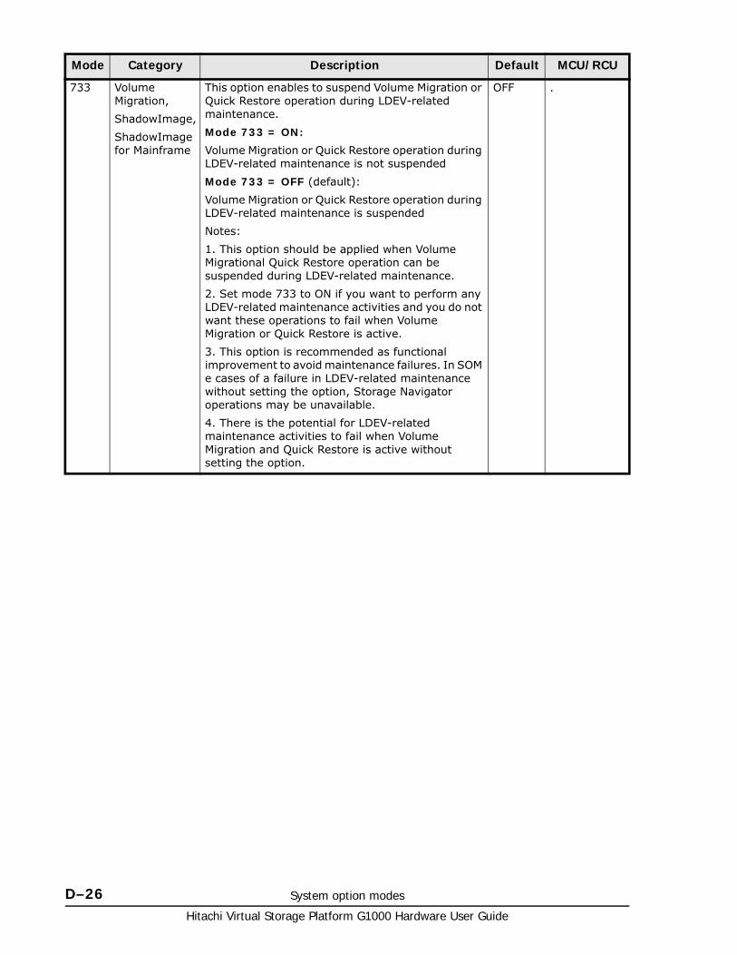
Hitachi Virtual Storage Platform G1000 Hardware User Guide
D–26 System option modes
733 Volume Migration,
ShadowImage,
ShadowImage for Mainframe
This option enables to suspend Volume Migration or Quick Restore operation during LDEV-related maintenance.
Mode 733 = ON:
Volume Migration or Quick Restore operation during LDEV-related maintenance is not suspended
Mode 733 = OFF (default):
Volume Migration or Quick Restore operation during LDEV-related maintenance is suspended
Notes:
1. This option should be applied when Volume Migrational Quick Restore operation can be suspended during LDEV-related maintenance.
2. Set mode 733 to ON if you want to perform any LDEV-related maintenance activities and you do not want these operations to fail when Volume Migration or Quick Restore is active.
3. This option is recommended as functional improvement to avoid maintenance failures. In SOM e cases of a failure in LDEV-related maintenance without setting the option, Storage Navigator operations may be unavailable.
4. There is the potential for LDEV-related maintenance activities to fail when Volume Migration and Quick Restore is active without setting the option.
OFF .
Mode Category Description Default MCU/RCU
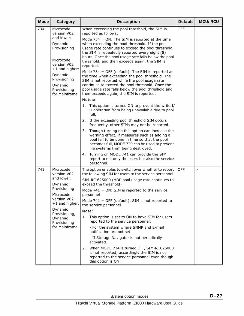
System option modes D–27Hitachi Virtual Storage Platform G1000 Hardware User Guide
734 Microcode version V02 and lower:
Dynamic Provisioning
Microcode version V02 +1 and higher:
Dynamic Provisioning
Dynamic Provisioning for Mainframe
When exceeding the pool threshold, the SIM is reported as follows:
Mode 734 = ON: The SIM is reported at the time when exceeding the pool threshold. If the pool usage rate continues to exceed the pool threshold, the SIM is repeatedly reported every eight (8) hours. Once the pool usage rate falls below the pool threshold, and then exceeds again, the SIM is reported.
Mode 734 = OFF (default): The SIM is reported at the time when exceeding the pool threshold. The SIM is not reported while the pool usage rate continues to exceed the pool threshold. Once the pool usage rate falls below the pool threshold and then exceeds again, the SIM is reported.
Notes:
1. This option is turned ON to prevent the write I/O operation from being unavailable due to pool full.
2. If the exceeding pool threshold SIM occurs frequently, other SIMs may not be reported.
3. Though turning on this option can increase the warning effect, if measures such as adding a pool fail to be done in time so that the pool becomes full, MODE 729 can be used to prevent file systems from being destroyed.
4. Turning on MODE 741 can provide the SIM report to not only the users but also the service personnel.
OFF .
741 Microcode version V02 and lower:
Dynamic Provisioning
Microcode version V02 +1 and higher:
Dynamic Provisioning, Dynamic Provisioning for Mainframe
The option enables to switch over whether to report the following SIM for users to the service personnel:
SIM-RC 625000 (HDP pool usage rate continues to exceed the threshold)
Mode 741 = ON: SIM is reported to the service personnel
Mode 741 = OFF (default): SIM is not reported to the service personnel
Note:
1. This option is set to ON to have SIM for users reported to the service personnel:
- For the system where SNMP and E-mail notification are not set.
- If Storage Navigator is not periodically activated.
2. When MODE 734 is turned OFF, SIM-RC625000 is not reported; accordingly the SIM is not reported to the service personnel even though this option is ON.
OFF -
Mode Category Description Default MCU/RCU
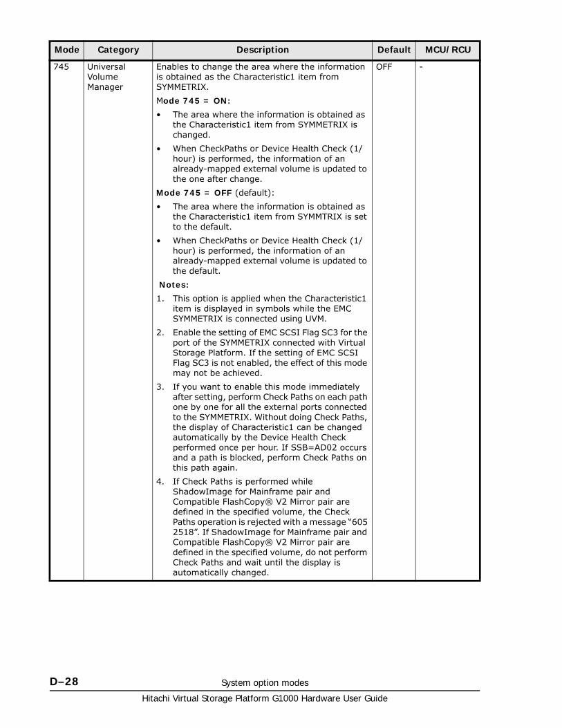
Hitachi Virtual Storage Platform G1000 Hardware User Guide
D–28 System option modes
745 Universal Volume Manager
Enables to change the area where the information is obtained as the Characteristic1 item from SYMMETRIX.
Mode 745 = ON:
• The area where the information is obtained as the Characteristic1 item from SYMMETRIX is changed.
• When CheckPaths or Device Health Check (1/hour) is performed, the information of an already-mapped external volume is updated to the one after change.
Mode 745 = OFF (default):
• The area where the information is obtained as the Characteristic1 item from SYMMTRIX is set to the default.
• When CheckPaths or Device Health Check (1/hour) is performed, the information of an already-mapped external volume is updated to the default.
Notes:
1. This option is applied when the Characteristic1 item is displayed in symbols while the EMC SYMMETRIX is connected using UVM.
2. Enable the setting of EMC SCSI Flag SC3 for the port of the SYMMETRIX connected with Virtual Storage Platform. If the setting of EMC SCSI Flag SC3 is not enabled, the effect of this mode may not be achieved.
3. If you want to enable this mode immediately after setting, perform Check Paths on each path one by one for all the external ports connected to the SYMMETRIX. Without doing Check Paths, the display of Characteristic1 can be changed automatically by the Device Health Check performed once per hour. If SSB=AD02 occurs and a path is blocked, perform Check Paths on this path again.
4. If Check Paths is performed while ShadowImage for Mainframe pair and Compatible FlashCopy® V2 Mirror pair are defined in the specified volume, the Check Paths operation is rejected with a message “605 2518”. If ShadowImage for Mainframe pair and Compatible FlashCopy® V2 Mirror pair are defined in the specified volume, do not perform Check Paths and wait until the display is automatically changed.
OFF -
Mode Category Description Default MCU/RCU
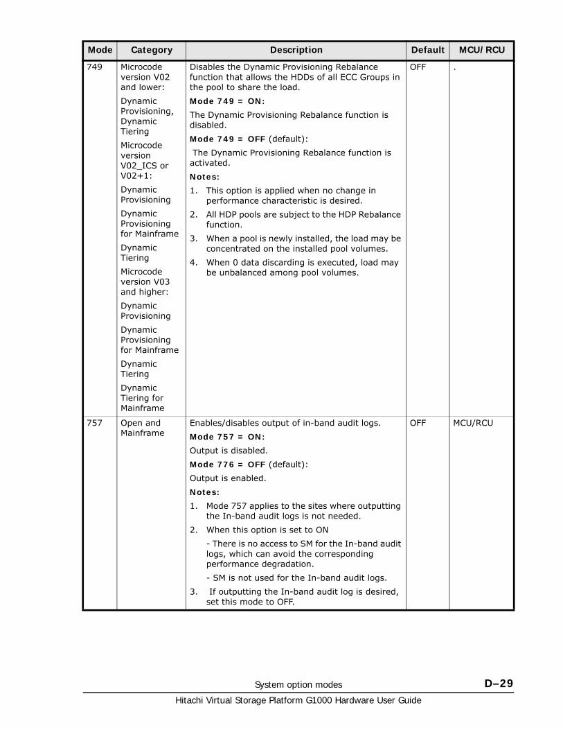
System option modes D–29Hitachi Virtual Storage Platform G1000 Hardware User Guide
749 Microcode version V02 and lower:
Dynamic Provisioning, Dynamic Tiering
Microcode version V02_ICS or V02+1:
Dynamic Provisioning
Dynamic Provisioning for Mainframe
Dynamic Tiering
Microcode version V03 and higher:
Dynamic Provisioning
Dynamic Provisioning for Mainframe
Dynamic Tiering
Dynamic Tiering for Mainframe
Disables the Dynamic Provisioning Rebalance function that allows the HDDs of all ECC Groups in the pool to share the load.
Mode 749 = ON:
The Dynamic Provisioning Rebalance function is disabled.
Mode 749 = OFF (default):
The Dynamic Provisioning Rebalance function is activated.
Notes:
1. This option is applied when no change in performance characteristic is desired.
2. All HDP pools are subject to the HDP Rebalance function.
3. When a pool is newly installed, the load may be concentrated on the installed pool volumes.
4. When 0 data discarding is executed, load may be unbalanced among pool volumes.
OFF .
757 Open and Mainframe
Enables/disables output of in-band audit logs.
Mode 757 = ON:
Output is disabled.
Mode 776 = OFF (default):
Output is enabled.
Notes:
1. Mode 757 applies to the sites where outputting the In-band audit logs is not needed.
2. When this option is set to ON
- There is no access to SM for the In-band audit logs, which can avoid the corresponding performance degradation.
- SM is not used for the In-band audit logs.
3. If outputting the In-band audit log is desired, set this mode to OFF.
OFF MCU/RCU
Mode Category Description Default MCU/RCU
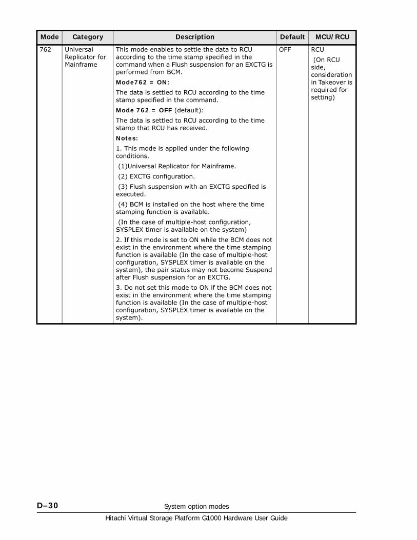
Hitachi Virtual Storage Platform G1000 Hardware User Guide
D–30 System option modes
762 Universal Replicator for Mainframe
This mode enables to settle the data to RCU according to the time stamp specified in the command when a Flush suspension for an EXCTG is performed from BCM.
Mode762 = ON:
The data is settled to RCU according to the time stamp specified in the command.
Mode 762 = OFF (default):
The data is settled to RCU according to the time stamp that RCU has received.
Notes:
1. This mode is applied under the following conditions.
(1)Universal Replicator for Mainframe.
(2) EXCTG configuration.
(3) Flush suspension with an EXCTG specified is executed.
(4) BCM is installed on the host where the time stamping function is available.
(In the case of multiple-host configuration, SYSPLEX timer is available on the system)
2. If this mode is set to ON while the BCM does not exist in the environment where the time stamping function is available (In the case of multiple-host configuration, SYSPLEX timer is available on the system), the pair status may not become Suspend after Flush suspension for an EXCTG.
3. Do not set this mode to ON if the BCM does not exist in the environment where the time stamping function is available (In the case of multiple-host configuration, SYSPLEX timer is available on the system).
OFF RCU
(On RCU side, consideration in Takeover is required for setting)
Mode Category Description Default MCU/RCU
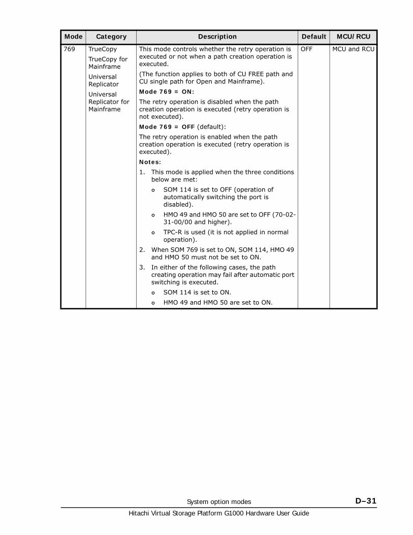
System option modes D–31Hitachi Virtual Storage Platform G1000 Hardware User Guide
769 TrueCopy
TrueCopy for Mainframe
Universal Replicator
Universal Replicator for Mainframe
This mode controls whether the retry operation is executed or not when a path creation operation is executed.
(The function applies to both of CU FREE path and CU single path for Open and Mainframe).
Mode 769 = ON:
The retry operation is disabled when the path creation operation is executed (retry operation is not executed).
Mode 769 = OFF (default):
The retry operation is enabled when the path creation operation is executed (retry operation is executed).
Notes:
1. This mode is applied when the three conditions below are met:
SOM 114 is set to OFF (operation of automatically switching the port is disabled).
HMO 49 and HMO 50 are set to OFF (70-02-31-00/00 and higher).
TPC-R is used (it is not applied in normal operation).
2. When SOM 769 is set to ON, SOM 114, HMO 49 and HMO 50 must not be set to ON.
3. In either of the following cases, the path creating operation may fail after automatic port switching is executed.
SOM 114 is set to ON.
HMO 49 and HMO 50 are set to ON.
OFF MCU and RCU
Mode Category Description Default MCU/RCU
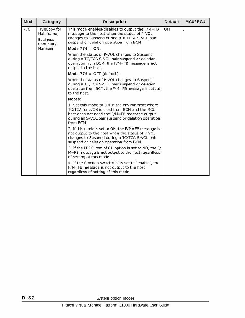
Hitachi Virtual Storage Platform G1000 Hardware User Guide
D–32 System option modes
776 TrueCopy for Mainframe,
Business Continuity Manager
This mode enables/disables to output the F/M=FB message to the host when the status of P-VOL changes to Suspend during a TC/TCA S-VOL pair suspend or deletion operation from BCM.
Mode 776 = ON:
When the status of P-VOL changes to Suspend during a TC/TCA S-VOL pair suspend or deletion operation from BCM, the F/M=FB message is not output to the host.
Mode 776 = OFF (default):
When the status of P-VOL changes to Suspend during a TC/TCA S-VOL pair suspend or deletion operation from BCM, the F/M=FB message is output to the host.
Notes:
1. Set this mode to ON in the environment where TC/TCA for z/OS is used from BCM and the MCU host does not need the F/M=FB message output during an S-VOL pair suspend or deletion operation from BCM.
2. If this mode is set to ON, the F/M=FB message is not output to the host when the status of P-VOL changes to Suspend during a TC/TCA S-VOL pair suspend or deletion operation from BCM
3. If the PPRC item of CU option is set to NO, the F/M=FB message is not output to the host regardless of setting of this mode.
4. If the function switch#07 is set to “enable”, the F/M=FB message is not output to the host regardless of setting of this mode.
OFF .
Mode Category Description Default MCU/RCU
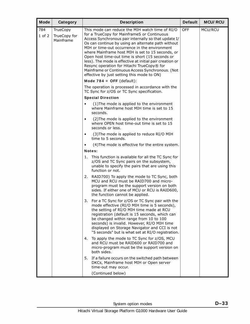
System option modes D–33Hitachi Virtual Storage Platform G1000 Hardware User Guide
784
1 of 2
TrueCopy
TrueCopy for Mainframe
This mode can reduce the MIH watch time of RI/O for a TrueCopy for MainframeS or Continuous Access Synchronous pair internally so that update I/Os can continue by using an alternate path without MIH or time-out occurrence in the environment where Mainframe host MIH is set to 15 seconds, or Open host time-out time is short (15 seconds or less). The mode is effective at initial pair creation or Resync operation for Hitachi TrueCopy® for Mainframe or Continuous Access Synchronous. (Not effective by just setting this mode to ON)
Mode 784 = OFF (default):
The operation is processed in accordance with the TC Sync for z/OS or TC Sync specification.
Special Direction
• (1)The mode is applied to the environment where Mainframe host MIH time is set to 15 seconds.
• (2)The mode is applied to the environment where OPEN host time-out time is set to 15 seconds or less.
• (3)The mode is applied to reduce RI/O MIH time to 5 seconds.
• (4)The mode is effective for the entire system.
Notes:
1. This function is available for all the TC Sync for z/OS and TC Sync pairs on the subsystem, unable to specify the pairs that are using this function or not.
2. RAID700) To apply the mode to TC Sync, both MCU and RCU must be RAID700 and micro-program must be the support version on both sides. If either one of MCU or RCU is RAID600, the function cannot be applied.
3. For a TC Sync for z/OS or TC Sync pair with the mode effective (RI/O MIH time is 5 seconds), the setting of RI/O MIH time made at RCU registration (default is 15 seconds, which can be changed within range from 10 to 100 seconds) is invalid. However, RI/O MIH time displayed on Storage Navigator and CCI is not "5 seconds" but is what set at RI/O registration.
4. To apply the mode to TC Sync for z/OS, MCU and RCU must be RAID600 or RAID700 and micro-program must be the support version on both sides.
5. If a failure occurs on the switched path between DKCs, Mainframe host MIH or Open server time-out may occur.
(Continued below)
OFF MCU/RCU
Mode Category Description Default MCU/RCU
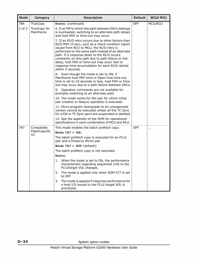
Hitachi Virtual Storage Platform G1000 Hardware User Guide
D–34 System option modes
784
2 of 2
TrueCopy
TrueCopy for Mainframe
Notes: (continued)
6. If an MP to which the path between DKCs belongs is overloaded, switching to an alternate path delays and host MIH or time-out may occur.
7. If an RI/O retry occurs due to other factors than RI/O MIH (5 sec), such as a check condition report issued from RCU to MCU, the RI/O retry is performed on the same path instead of an alternate path. If a response delay to the RI/O occurs constantly on this path due to path failure or link delay, host MIH or time-out may occur due to response time accumulation for each RI/O retried within 5 seconds.
8. Even though the mode is set to ON, if Mainframe host MIH time or Open host time-out time is set to 10 seconds or less, host MIH or time-out may occur due to a path failure between DKCs.
9. Operation commands are not available for promptly switching to an alternate path.
10. The mode works for the pair for which initial pair creation or Resync operation is executed.
11. Micro-program downgrade to an unsupported version cannot be executed unless all the TC Sync for z/OS or TC Sync pairs are suspended or deleted.
12. See the appendix of the SOM for operational specifications in each combination of MCU and RCU.
OFF MCU/RCU
787 Compatible FlashCopy(R) V2
This mode enables the batch prefetch copy.
Mode 787 = ON:
The batch prefetch copy is executed for an FCv2 pair and a Preserve Mirror pair
Mode 787 = OFF (default):
The batch prefetch copy is not executed.
Notes:
1. When the mode is set to ON, the performance characteristic regarding sequential I/Os to the FCv2target VOL changes.
2. The mode is applied only when SOM 577 is set to OFF
3. The mode is applied if response performance for a host I/O issued to the FCv2 target VOL is prioritized
OFF ..
Mode Category Description Default MCU/RCU
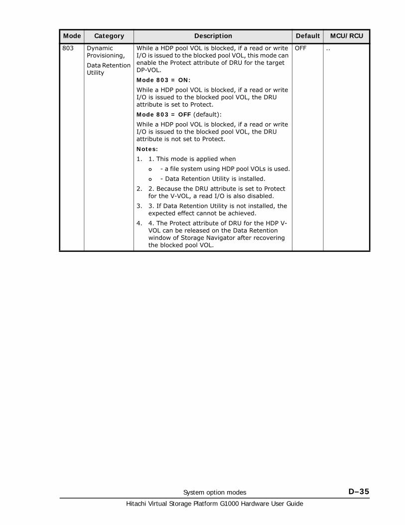
System option modes D–35Hitachi Virtual Storage Platform G1000 Hardware User Guide
803 Dynamic Provisioning,
Data Retention Utility
While a HDP pool VOL is blocked, if a read or write I/O is issued to the blocked pool VOL, this mode can enable the Protect attribute of DRU for the target DP-VOL.
Mode 803 = ON:
While a HDP pool VOL is blocked, if a read or write I/O is issued to the blocked pool VOL, the DRU attribute is set to Protect.
Mode 803 = OFF (default):
While a HDP pool VOL is blocked, if a read or write I/O is issued to the blocked pool VOL, the DRU attribute is not set to Protect.
Notes:
1. 1. This mode is applied when
- a file system using HDP pool VOLs is used.
- Data Retention Utility is installed.
2. 2. Because the DRU attribute is set to Protect for the V-VOL, a read I/O is also disabled.
3. 3. If Data Retention Utility is not installed, the expected effect cannot be achieved.
4. 4. The Protect attribute of DRU for the HDP V-VOL can be released on the Data Retention window of Storage Navigator after recovering the blocked pool VOL.
OFF ..
Mode Category Description Default MCU/RCU
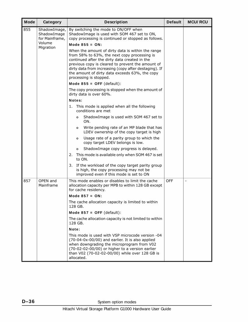
Hitachi Virtual Storage Platform G1000 Hardware User Guide
D–36 System option modes
855 ShadowImage, ShadowImage for Mainframe, Volume Migration
By switching the mode to ON/OFF when ShadowImage is used with SOM 467 set to ON, copy processing is continued or stopped as follows.
Mode 855 = ON:
When the amount of dirty data is within the range from 58% to 63%, the next copy processing is continued after the dirty data created in the previous copy is cleared to prevent the amount of dirty data from increasing (copy after destaging). If the amount of dirty data exceeds 63%, the copy processing is stopped.
Mode 855 = OFF (default):
The copy processing is stopped when the amount of dirty data is over 60%.
Notes:
1. This mode is applied when all the following conditions are met
ShadowImage is used with SOM 467 set to ON.
Write pending rate of an MP blade that has LDEV ownership of the copy target is high
Usage rate of a parity group to which the copy target LDEV belongs is low.
ShadowImage copy progress is delayed.
2. This mode is available only when SOM 467 is set to ON.
3. If the workload of the copy target parity group is high, the copy processing may not be improved even if this mode is set to ON
857 OPEN and Mainframe
This mode enables or disables to limit the cache allocation capacity per MPB to within 128 GB except for cache residency.
Mode 857 = ON:
The cache allocation capacity is limited to within 128 GB.
Mode 857 = OFF (default):
The cache allocation capacity is not limited to within 128 GB.
Note:
This mode is used with VSP microcode version -04 (70-04-0x-00/00) and earlier. It is also applied when downgrading the microprogram from V02 (70-02-02-00/00) or higher to a version earlier than V02 (70-02-02-00/00) while over 128 GB is allocated.
OFF -
Mode Category Description Default MCU/RCU
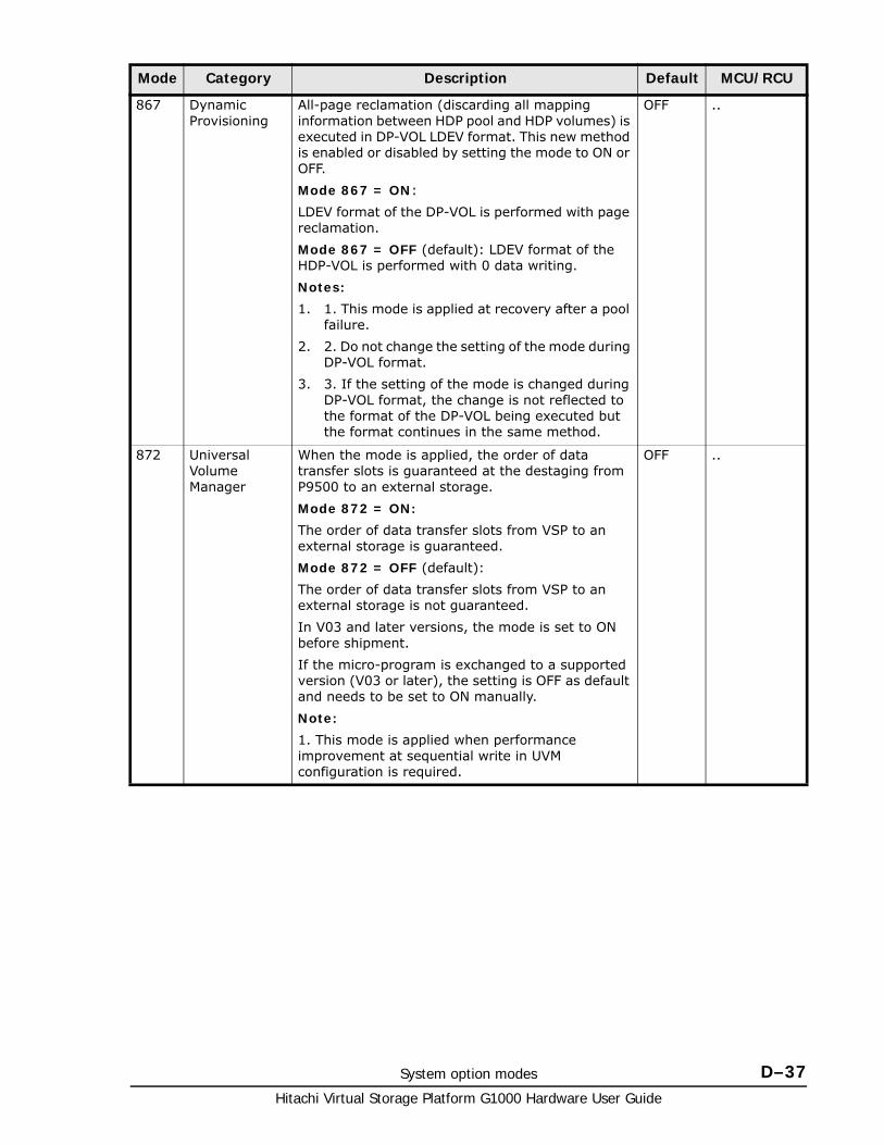
System option modes D–37Hitachi Virtual Storage Platform G1000 Hardware User Guide
867 Dynamic Provisioning
All-page reclamation (discarding all mapping information between HDP pool and HDP volumes) is executed in DP-VOL LDEV format. This new method is enabled or disabled by setting the mode to ON or OFF.
Mode 867 = ON:
LDEV format of the DP-VOL is performed with page reclamation.
Mode 867 = OFF (default): LDEV format of the HDP-VOL is performed with 0 data writing.
Notes:
1. 1. This mode is applied at recovery after a pool failure.
2. 2. Do not change the setting of the mode during DP-VOL format.
3. 3. If the setting of the mode is changed during DP-VOL format, the change is not reflected to the format of the DP-VOL being executed but the format continues in the same method.
OFF ..
872 Universal Volume Manager
When the mode is applied, the order of data transfer slots is guaranteed at the destaging from P9500 to an external storage.
Mode 872 = ON:
The order of data transfer slots from VSP to an external storage is guaranteed.
Mode 872 = OFF (default):
The order of data transfer slots from VSP to an external storage is not guaranteed.
In V03 and later versions, the mode is set to ON before shipment.
If the micro-program is exchanged to a supported version (V03 or later), the setting is OFF as default and needs to be set to ON manually.
Note:
1. This mode is applied when performance improvement at sequential write in UVM configuration is required.
OFF ..
Mode Category Description Default MCU/RCU
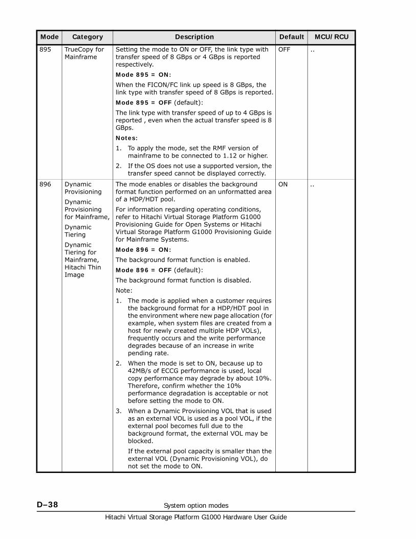
Hitachi Virtual Storage Platform G1000 Hardware User Guide
D–38 System option modes
895 TrueCopy for Mainframe
Setting the mode to ON or OFF, the link type with transfer speed of 8 GBps or 4 GBps is reported respectively.
Mode 895 = ON:
When the FICON/FC link up speed is 8 GBps, the link type with transfer speed of 8 GBps is reported.
Mode 895 = OFF (default):
The link type with transfer speed of up to 4 GBps is reported , even when the actual transfer speed is 8 GBps.
Notes:
1. To apply the mode, set the RMF version of mainframe to be connected to 1.12 or higher.
2. If the OS does not use a supported version, the transfer speed cannot be displayed correctly.
OFF ..
896 Dynamic Provisioning
Dynamic Provisioning for Mainframe,
Dynamic Tiering
Dynamic Tiering for Mainframe, Hitachi Thin Image
The mode enables or disables the background format function performed on an unformatted area of a HDP/HDT pool.
For information regarding operating conditions, refer to Hitachi Virtual Storage Platform G1000 Provisioning Guide for Open Systems or Hitachi Virtual Storage Platform G1000 Provisioning Guide for Mainframe Systems.
Mode 896 = ON:
The background format function is enabled.
Mode 896 = OFF (default):
The background format function is disabled.
Note:
1. The mode is applied when a customer requires the background format for a HDP/HDT pool in the environment where new page allocation (for example, when system files are created from a host for newly created multiple HDP VOLs), frequently occurs and the write performance degrades because of an increase in write pending rate.
2. When the mode is set to ON, because up to 42MB/s of ECCG performance is used, local copy performance may degrade by about 10%. Therefore, confirm whether the 10% performance degradation is acceptable or not before setting the mode to ON.
3. When a Dynamic Provisioning VOL that is used as an external VOL is used as a pool VOL, if the external pool becomes full due to the background format, the external VOL may be blocked.
If the external pool capacity is smaller than the external VOL (Dynamic Provisioning VOL), do not set the mode to ON.
ON ..
Mode Category Description Default MCU/RCU
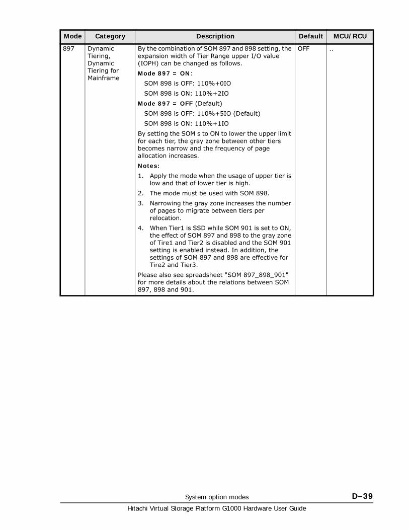
System option modes D–39Hitachi Virtual Storage Platform G1000 Hardware User Guide
897 Dynamic Tiering, Dynamic Tiering for Mainframe
By the combination of SOM 897 and 898 setting, the expansion width of Tier Range upper I/O value (IOPH) can be changed as follows.
Mode 897 = ON:
SOM 898 is OFF: 110%+0IO
SOM 898 is ON: 110%+2IO
Mode 897 = OFF (Default)
SOM 898 is OFF: 110%+5IO (Default)
SOM 898 is ON: 110%+1IO
By setting the SOM s to ON to lower the upper limit for each tier, the gray zone between other tiers becomes narrow and the frequency of page allocation increases.
Notes:
1. Apply the mode when the usage of upper tier is low and that of lower tier is high.
2. The mode must be used with SOM 898.
3. Narrowing the gray zone increases the number of pages to migrate between tiers per relocation.
4. When Tier1 is SSD while SOM 901 is set to ON, the effect of SOM 897 and 898 to the gray zone of Tire1 and Tier2 is disabled and the SOM 901 setting is enabled instead. In addition, the settings of SOM 897 and 898 are effective for Tire2 and Tier3.
Please also see spreadsheet "SOM 897_898_901" for more details about the relations between SOM 897, 898 and 901.
OFF ..
Mode Category Description Default MCU/RCU
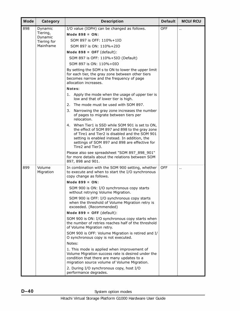
Hitachi Virtual Storage Platform G1000 Hardware User Guide
D–40 System option modes
898 Dynamic Tiering, Dynamic Tiering for Mainframe
I/O value (IOPH) can be changed as follows.
Mode 898 = ON:
SOM 897 is OFF: 110%+1IO
SOM 897 is ON: 110%+2IO
Mode 898 = OFF (default):
SOM 897 is OFF: 110%+5IO (Default)
SOM 897 is ON: 110%+0IO
By setting the SOM s to ON to lower the upper limit for each tier, the gray zone between other tiers becomes narrow and the frequency of page allocation increases.
Notes:
1. Apply the mode when the usage of upper tier is low and that of lower tier is high.
2. The mode must be used with SOM 897.
3. Narrowing the gray zone increases the number of pages to migrate between tiers per relocation.
4. When Tier1 is SSD while SOM 901 is set to ON, the effect of SOM 897 and 898 to the gray zone of Tire1 and Tier2 is disabled and the SOM 901 setting is enabled instead. In addition, the settings of SOM 897 and 898 are effective for Tire2 and Tier3.
Please also see spreadsheet "SOM 897_898_901" for more details about the relations between SOM 897, 898 and 901.
OFF ..
899 Volume Migration
In combination with the SOM 900 setting, whether to execute and when to start the I/O synchronous copy change as follows.
Mode 899 = ON:
SOM 900 is ON: I/O synchronous copy starts without retrying Volume Migration.
SOM 900 is OFF: I/O synchronous copy starts when the threshold of Volume Migration retry is exceeded. (Recommended)
Mode 899 = OFF (default):
SOM 900 is ON: I/O synchronous copy starts when the number of retries reaches half of the threshold of Volume Migration retry.
SOM 900 is OFF: Volume Migration is retired and I/O synchronous copy is not executed.
Notes:
1. This mode is applied when improvement of Volume Migration success rate is desired under the condition that there are many updates to a migration source volume of Volume Migration.
2. During I/O synchronous copy, host I/O performance degrades.
OFF ..
Mode Category Description Default MCU/RCU
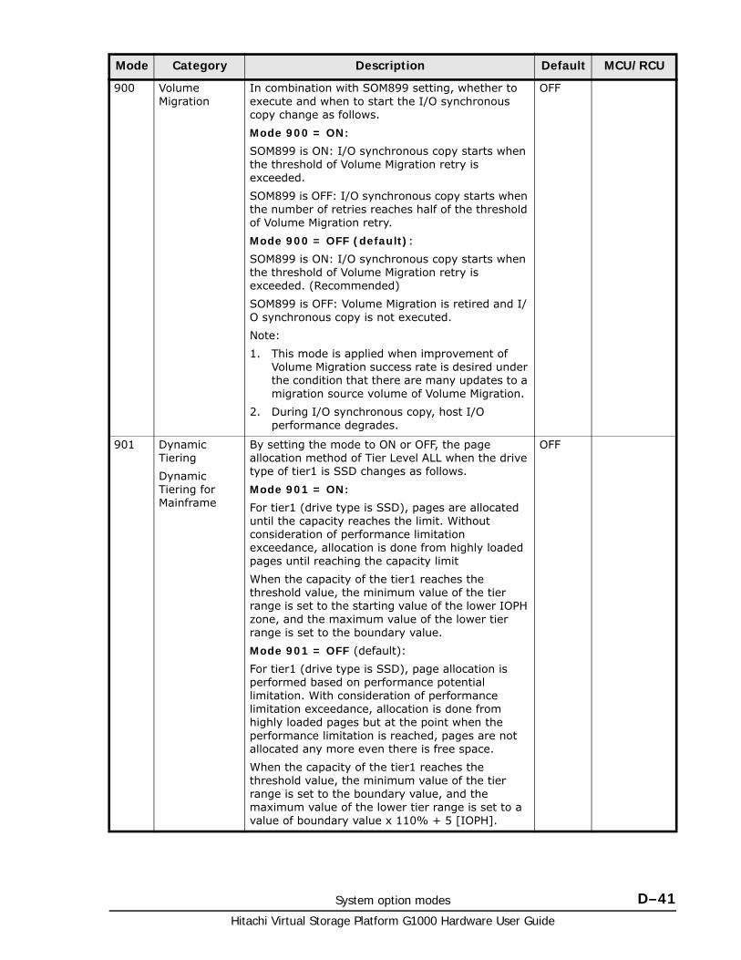
System option modes D–41Hitachi Virtual Storage Platform G1000 Hardware User Guide
900 Volume Migration
In combination with SOM899 setting, whether to execute and when to start the I/O synchronous copy change as follows.
Mode 900 = ON:
SOM899 is ON: I/O synchronous copy starts when the threshold of Volume Migration retry is exceeded.
SOM899 is OFF: I/O synchronous copy starts when the number of retries reaches half of the threshold of Volume Migration retry.
Mode 900 = OFF (default):
SOM899 is ON: I/O synchronous copy starts when the threshold of Volume Migration retry is exceeded. (Recommended)
SOM899 is OFF: Volume Migration is retired and I/O synchronous copy is not executed.
Note:
1. This mode is applied when improvement of Volume Migration success rate is desired under the condition that there are many updates to a migration source volume of Volume Migration.
2. During I/O synchronous copy, host I/O performance degrades.
OFF
901 Dynamic Tiering
Dynamic Tiering for Mainframe
By setting the mode to ON or OFF, the page allocation method of Tier Level ALL when the drive type of tier1 is SSD changes as follows.
Mode 901 = ON:
For tier1 (drive type is SSD), pages are allocated until the capacity reaches the limit. Without consideration of performance limitation exceedance, allocation is done from highly loaded pages until reaching the capacity limit
When the capacity of the tier1 reaches the threshold value, the minimum value of the tier range is set to the starting value of the lower IOPH zone, and the maximum value of the lower tier range is set to the boundary value.
Mode 901 = OFF (default):
For tier1 (drive type is SSD), page allocation is performed based on performance potential limitation. With consideration of performance limitation exceedance, allocation is done from highly loaded pages but at the point when the performance limitation is reached, pages are not allocated any more even there is free space.
When the capacity of the tier1 reaches the threshold value, the minimum value of the tier range is set to the boundary value, and the maximum value of the lower tier range is set to a value of boundary value x 110% + 5 [IOPH].
OFF
Mode Category Description Default MCU/RCU
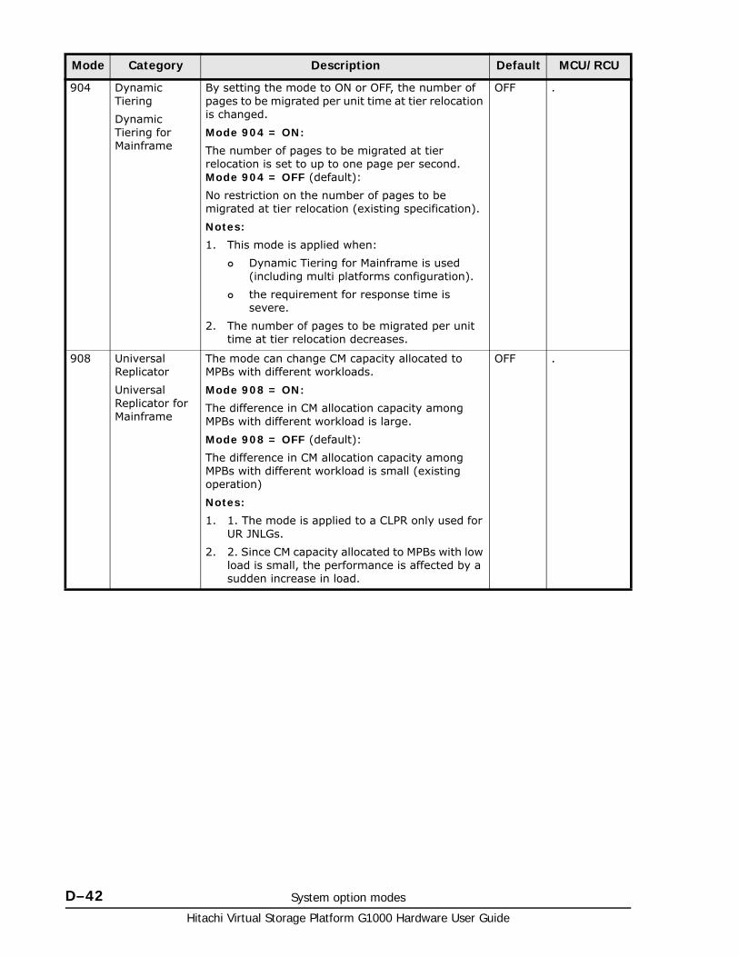
Hitachi Virtual Storage Platform G1000 Hardware User Guide
D–42 System option modes
904 Dynamic Tiering
Dynamic Tiering for Mainframe
By setting the mode to ON or OFF, the number of pages to be migrated per unit time at tier relocation is changed.
Mode 904 = ON:
The number of pages to be migrated at tier relocation is set to up to one page per second. Mode 904 = OFF (default):
No restriction on the number of pages to be migrated at tier relocation (existing specification).
Notes:
1. This mode is applied when:
Dynamic Tiering for Mainframe is used (including multi platforms configuration).
the requirement for response time is severe.
2. The number of pages to be migrated per unit time at tier relocation decreases.
OFF .
908 Universal Replicator
Universal Replicator for Mainframe
The mode can change CM capacity allocated to MPBs with different workloads.
Mode 908 = ON:
The difference in CM allocation capacity among MPBs with different workload is large.
Mode 908 = OFF (default):
The difference in CM allocation capacity among MPBs with different workload is small (existing operation)
Notes:
1. 1. The mode is applied to a CLPR only used for UR JNLGs.
2. 2. Since CM capacity allocated to MPBs with low load is small, the performance is affected by a sudden increase in load.
OFF .
Mode Category Description Default MCU/RCU
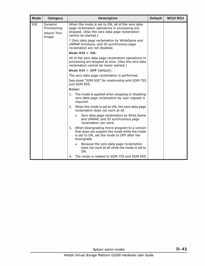
System option modes D–43Hitachi Virtual Storage Platform G1000 Hardware User Guide
930 Dynamic Provisioning
Hitachi Thin Image
When the mode is set to ON, all of the zero data page reclamation operations in processing are stopped. (Also the zero data page reclamation cannot be started.)
* Zero data page reclamation by WriteSame and UNMAP functions, and IO synchronous page reclamation are not disabled.
Mode 930 = ON:
All of the zero data page reclamation operations in processing are stopped at once. (Also the zero data reclamation cannot be newly started.)
Mode 930 = OFF (default):
The zero data page reclamation is performed.
See sheet "SOM 930" for relationship with SOM 755 and SOM 859.
Notes:
1. The mode is applied when stopping or disabling zero data page reclamation by user request is required.
2. When the mode is set to ON, the zero data page reclamation does not work at all.
Zero data page reclamation by Write Same and UNMAP, and IO synchronous page reclamation can work.
3. When downgrading micro-program to a version that does not support the mode while the mode is set to ON, set the mode to OFF after the downgrade
Because the zero data page reclamation does not work at all while the mode is set to ON.
4. The mode is related to SOM 755 and SOM 859.
Mode Category Description Default MCU/RCU
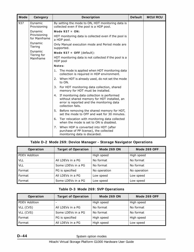
Hitachi Virtual Storage Platform G1000 Hardware User Guide
D–44 System option modes
Table D-2 Mode 269: Device Manager - Storage Navigator Operations
Table D-3 Mode 269: SVP Operations
937 Dynamic Provisioning
Dynamic Provisioning for Mainframe
Dynamic Tiering
Dynamic Tiering for Mainframe
By setting the mode to ON, HDT monitoring data is collected even if the pool is a HDP pool.
Mode 937 = ON:
HDT monitoring data is collected even if the pool is a HDP pool.
Only Manual execution mode and Period mode are supported.
Mode 937 = OFF (default):
HDT monitoring data is not collected if the pool is a HDP pool
Notes:
1. The mode is applied when HDT monitoring data collection is required in HDP environment.
2. When HDT is already used, do not set the mode to ON.
3. For HDT monitoring data collection, shared memory for HDT must be installed.
4. If monitoring data collection is performed without shared memory for HDT installed, an error is reported and the monitoring data collection fails.
5. Before removing the shared memory for HDT, set the mode to OFF and wait for 30 minutes.
6. Tier relocation with monitoring data collected when the mode is set to ON is disabled.
7. When HDP is converted into HDT (after purchase of PP license), the collected monitoring data is discarded.
Operation Target of Operation Mode 269 ON Mode 269 OFF
PDEV Addition High speed High speed
VLL All LDEVs in a PG No format No format
VLL Some LDEVs in a PG No format No format
Format PG is specified No operation No operation
Format All LDEVs in a PG Low speed Low speed
Format Some LDEVs in a PG Low speed Low speed
Operation Target of Operation Mode 269 ON Mode 269 OFF
PDEV Addition - High speed High speed
VLL (CVS) All LDEVs in a PG No format No format
VLL (CVS) Some LDEVs in a PG No format No format
Format PG is specified High speed High speed
Format All LDEVs in a PG High speed Low speed
Mode Category Description Default MCU/RCU
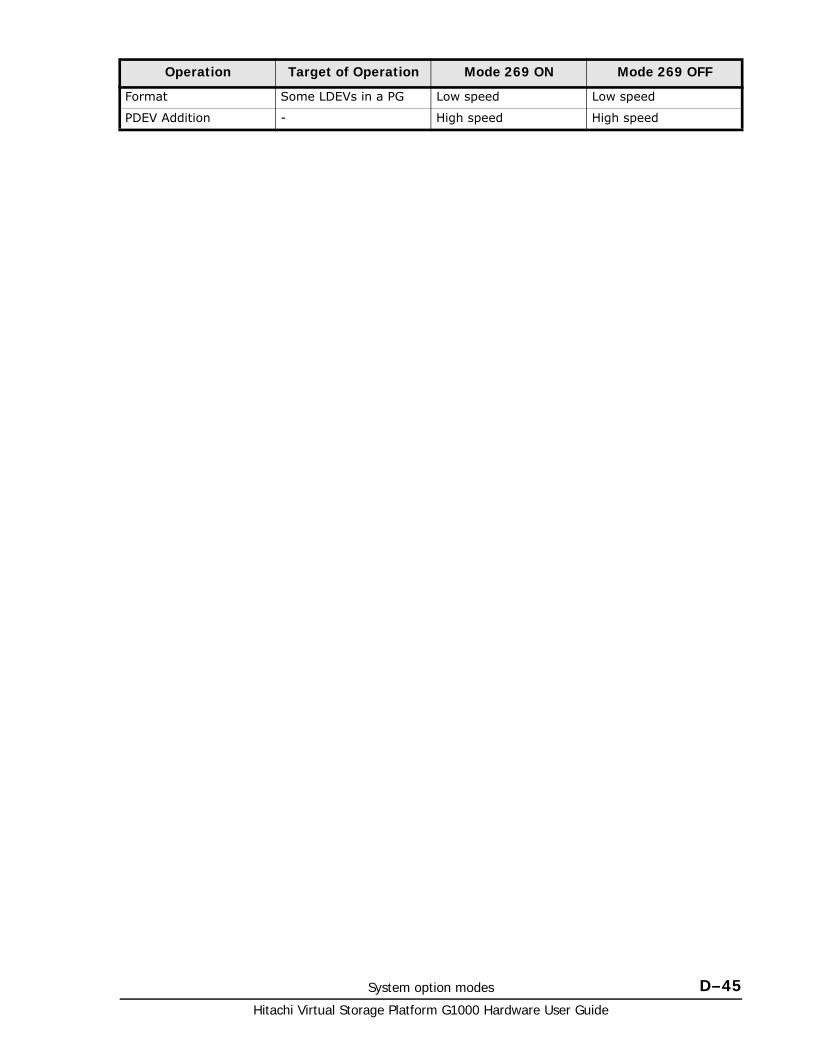
System option modes D–45Hitachi Virtual Storage Platform G1000 Hardware User Guide
Format Some LDEVs in a PG Low speed Low speed
PDEV Addition - High speed High speed
Operation Target of Operation Mode 269 ON Mode 269 OFF

Hitachi Virtual Storage Platform G1000 Hardware User Guide
D–46 System option modes
E
Regulatory Compliance E–1Hitachi Virtual Storage Platform G1000 Hardware User Guide
Regulatory Compliance
This appendix includes a comprehensive set of specifications for the VSP G1000 storage system storage system described in this manual. The Regulatory Compliance section includes a table of regulatory specifications that are met by the VSP G1000 storage system. Following the tables are individual regulatory statements that explain the requirements of various countries.
□ Regulatory compliance
□ US FCC Notice
□ European Declaration of Conformity
□ Notice of export controls
□ Hazardous and toxic substances
□ Disposal
□ Recycling
□ Electronic emissions certificates
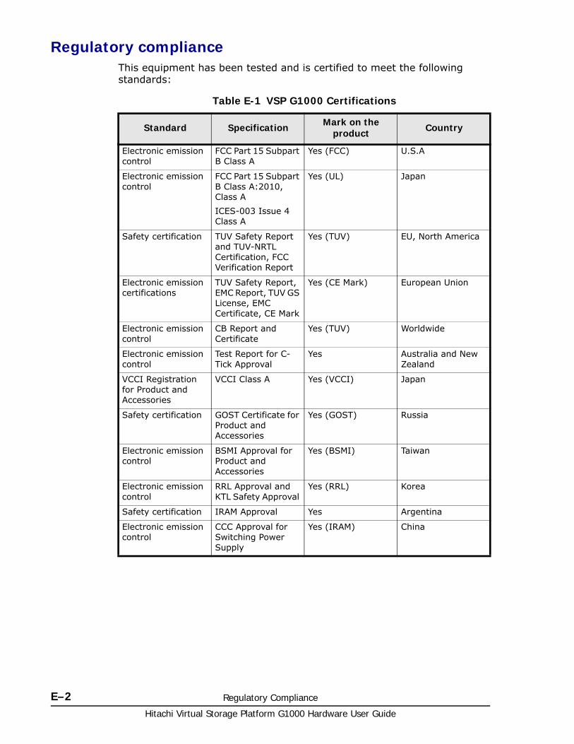
Hitachi Virtual Storage Platform G1000 Hardware User Guide
E–2 Regulatory Compliance
Regulatory complianceThis equipment has been tested and is certified to meet the following standards:
Table E-1 VSP G1000 Certifications
Standard Specification Mark on the product Country
Electronic emission control
FCC Part 15 Subpart B Class A
Yes (FCC) U.S.A
Electronic emission control
FCC Part 15 Subpart B Class A:2010, Class A
ICES-003 Issue 4 Class A
Yes (UL) Japan
Safety certification TUV Safety Report and TUV-NRTL Certification, FCC Verification Report
Yes (TUV) EU, North America
Electronic emission certifications
TUV Safety Report, EMC Report, TUV GS License, EMC Certificate, CE Mark
Yes (CE Mark) European Union
Electronic emission control
CB Report and Certificate
Yes (TUV) Worldwide
Electronic emission control
Test Report for C-Tick Approval
Yes Australia and New Zealand
VCCI Registration for Product and Accessories
VCCI Class A Yes (VCCI) Japan
Safety certification GOST Certificate for Product and Accessories
Yes (GOST) Russia
Electronic emission control
BSMI Approval for Product and Accessories
Yes (BSMI) Taiwan
Electronic emission control
RRL Approval and KTL Safety Approval
Yes (RRL) Korea
Safety certification IRAM Approval Yes Argentina
Electronic emission control
CCC Approval for Switching Power Supply
Yes (IRAM) China
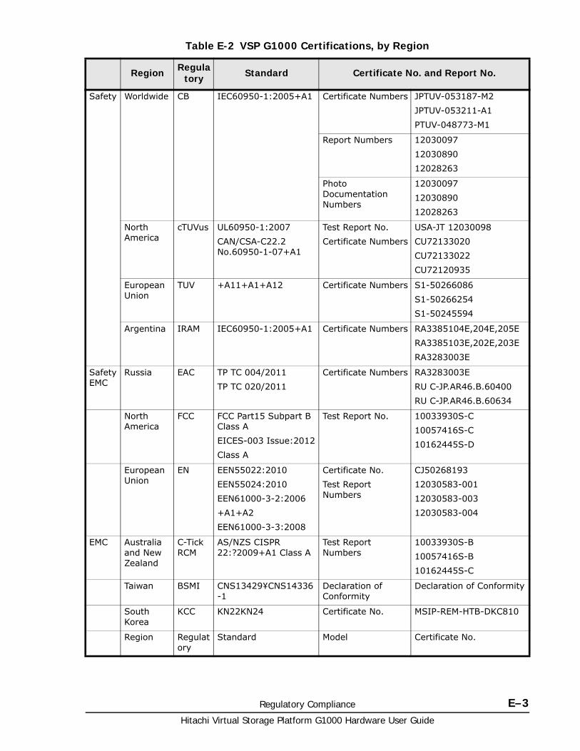
Regulatory Compliance E–3Hitachi Virtual Storage Platform G1000 Hardware User Guide
Table E-2 VSP G1000 Certifications, by Region
Region Regulatory Standard Certificate No. and Report No.
Safety Worldwide CB IEC60950-1:2005+A1 Certificate Numbers JPTUV-053187-M2
JPTUV-053211-A1
PTUV-048773-M1
Report Numbers 12030097
12030890
12028263
Photo Documentation Numbers
12030097
12030890
12028263
North America
cTUVus UL60950-1:2007
CAN/CSA-C22.2 No.60950-1-07+A1
Test Report No.
Certificate Numbers
USA-JT 12030098
CU72133020
CU72133022
CU72120935
European Union
TUV +A11+A1+A12 Certificate Numbers S1-50266086
S1-50266254
S1-50245594
Argentina IRAM IEC60950-1:2005+A1 Certificate Numbers RA3385104E,204E,205E
RA3385103E,202E,203E
RA3283003E
Safety EMC
Russia EAC TP TC 004/2011
TP TC 020/2011
Certificate Numbers RA3283003E
RU C-JP.AR46.B.60400
RU C-JP.AR46.B.60634
North America
FCC FCC Part15 Subpart B Class A
EICES-003 Issue:2012
Class A
Test Report No. 10033930S-C
10057416S-C
10162445S-D
European Union
EN EEN55022:2010
EEN55024:2010
EEN61000-3-2:2006
+A1+A2
EEN61000-3-3:2008
Certificate No.
Test Report Numbers
CJ50268193
12030583-001
12030583-003
12030583-004
EMC Australia and New Zealand
C-Tick RCM
AS/NZS CISPR 22:?2009+A1 Class A
Test Report Numbers
10033930S-B
10057416S-B
10162445S-C
Taiwan BSMI CNS13429¥CNS14336-1
Declaration of Conformity
Declaration of Conformity
South Korea
KCC KN22KN24 Certificate No. MSIP-REM-HTB-DKC810
Region Regulatory
Standard Model Certificate No.
Hitachi Virtual Storage Platform G1000 Hardware User Guide
E–4 Regulatory Compliance
US FCC NoticeFCC Notice
Federal Communications Commission
This equipment has been tested and found to comply with the limits for a Class A digital device, pursuant to part 15 of the FCC Rules. These limits are designed to provide reasonable protection against harmful interference when the equipment is operated in a commercial environment.
This equipment generates, uses, and can radiate radio frequency energy and, if not installed and used in accordance with the instruction manual, may cause harmful interference to radio communications. Operation of this equipment in a residential area is likely to cause harmful interference, in which case users will be required to correct the interference at their own expense.
Electronic emissions testingEMI testing was done with shielded cables. Therefore, in order to comply with the FCC regulations, you must use shielded cables with your installation.
The EMI tests were done in the following configurations:
DKC710I-CBX+DKC+F710I-SBX
DKC710I-CBX+DKC+F710I-SBX+DKC-F710I-UBX
Copies of the Underwriters Laboratories EMI compliance certificates are located at the end of this chapter.
If trouble occurs in another configuration, a user may be requested to take appropriate preventive measures.
European Declaration of Conformity
Safety EMC
China CCC GB4943-2011GB9254-2008GB17625.1-2003
SBX/UBX_SWPSTDPS-600FB XX
2011010907455767
FBX_SWPSPPD6001
2012010907575263
Region Regulatory Standard Certificate No. and Report No.
Warning This equipment complies with the requirements relating to electromagnetic compatibility, EN 55022 class A for ITE, the essential protection requirement of Council Directive 89/336/EEC on the approximation of the laws of the Member States relating to electromagnetic compatibility.
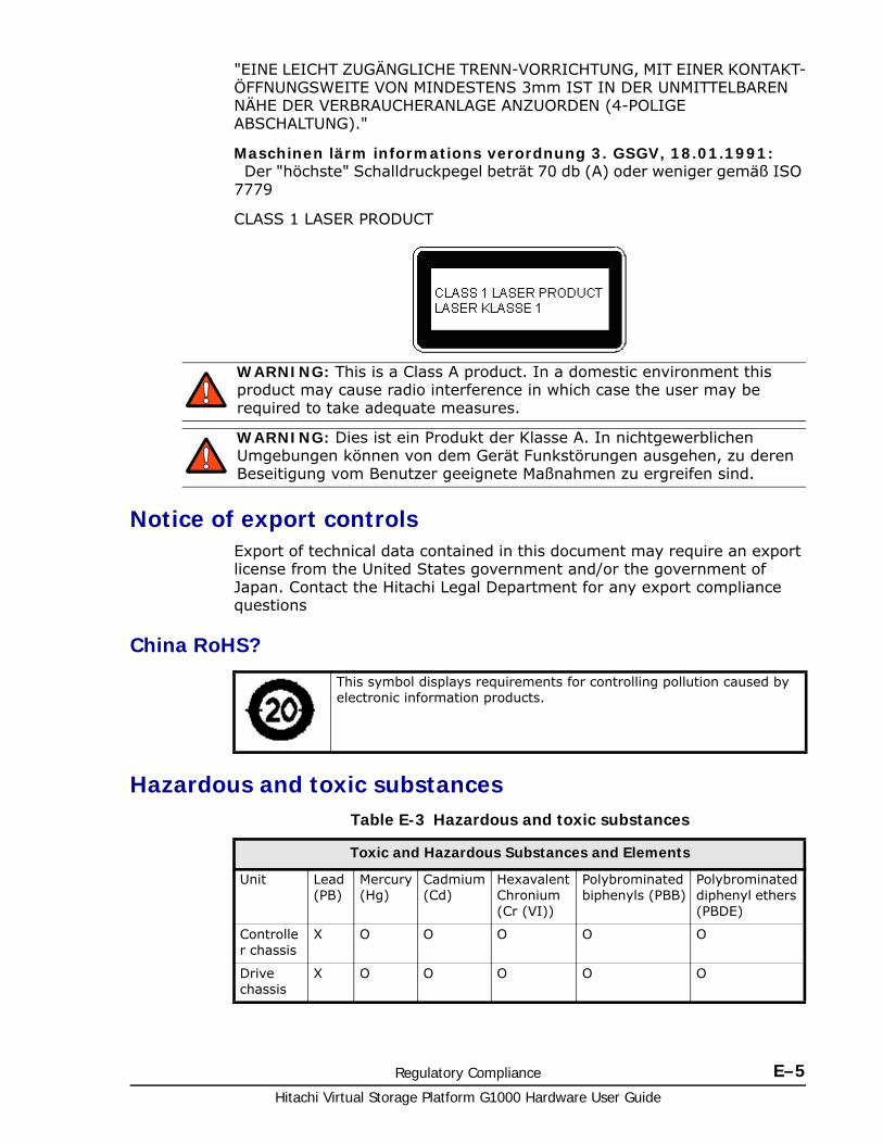
Regulatory Compliance E–5Hitachi Virtual Storage Platform G1000 Hardware User Guide
"EINE LEICHT ZUGÄNGLICHE TRENN-VORRICHTUNG, MIT EINER KONTAKT-ÖFFNUNGSWEITE VON MINDESTENS 3mm IST IN DER UNMITTELBAREN NÄHE DER VERBRAUCHERANLAGE ANZUORDEN (4-POLIGE ABSCHALTUNG)."
Maschinen lärm informations verordnung 3. GSGV, 18.01.1991: Der "höchste" Schalldruckpegel beträt 70 db (A) oder weniger gemäß ISO
7779
CLASS 1 LASER PRODUCT
Notice of export controlsExport of technical data contained in this document may require an export license from the United States government and/or the government of Japan. Contact the Hitachi Legal Department for any export compliance questions
China RoHS?
Hazardous and toxic substancesTable E-3 Hazardous and toxic substances
WARNING: This is a Class A product. In a domestic environment this product may cause radio interference in which case the user may be required to take adequate measures.
WARNING: Dies ist ein Produkt der Klasse A. In nichtgewerblichen Umgebungen können von dem Gerät Funkstörungen ausgehen, zu deren Beseitigung vom Benutzer geeignete Maßnahmen zu ergreifen sind.
This symbol displays requirements for controlling pollution caused by electronic information products.
Toxic and Hazardous Substances and Elements
Unit Lead (PB)
Mercury (Hg)
Cadmium (Cd)
Hexavalent Chronium (Cr (VI))
Polybrominated biphenyls (PBB)
Polybrominated diphenyl ethers (PBDE)
Controller chassis
X O O O O O
Drive chassis
X O O O O O
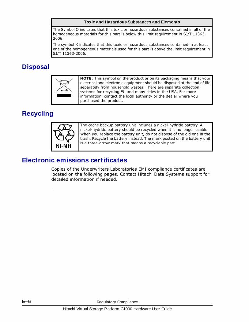
Hitachi Virtual Storage Platform G1000 Hardware User Guide
E–6 Regulatory Compliance
Disposal
Recycling
Electronic emissions certificatesCopies of the Underwriters Laboratories EMI compliance certificates are located on the following pages. Contact Hitachi Data Systems support for detailed information if needed.
.
The Symbol O indicates that this toxic or hazardous substances contained in all of the homogeneous materials for this part is below this limit requirement in SJ/T 11363-2006.
The symbol X indicates that this toxic or hazardous substances contained in at least one of the homogeneous materials used for this part is above the limit requirement in SJ/T 11363-2006.
NOTE: This symbol on the product or on its packaging means that your electrical and electronic equipment should be disposed at the end of life separately from household wastes. There are separate collection systems for recycling EU and many cities in the USA. For more information, contact the local authority or the dealer where you purchased the product.
The cache backup battery unit includes a nickel-hydride battery. A nickel-hydride battery should be recycled when it is no longer usable. When you replace the battery unit, do not dispose of the old one in the trash. Recycle the battery instead. The mark posted on the battery unit is a three-arrow mark that means a recyclable part.
Toxic and Hazardous Substances and Elements

Regulatory Compliance E–7Hitachi Virtual Storage Platform G1000 Hardware User Guide
Hitachi Virtual Storage Platform G1000 Hardware User Guide
E–8 Regulatory Compliance

Regulatory Compliance E–9Hitachi Virtual Storage Platform G1000 Hardware User Guide
Hitachi Virtual Storage Platform G1000 Hardware User Guide
E–10 Regulatory Compliance

Regulatory Compliance E–11Hitachi Virtual Storage Platform G1000 Hardware User Guide
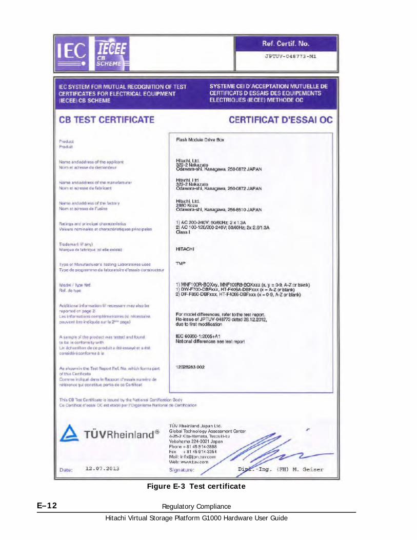
Hitachi Virtual Storage Platform G1000 Hardware User Guide
E–12 Regulatory Compliance
Figure E-3 Test certificate
CA KD E F G H I J L M N O P Q R S T U V W X Y# B ZA B C D F J K L P R S V
Glossary–1Hitachi Virtual Storage Platform G1000 Hardware User Guide
Glossary
This glossary defines the special terms used in this document.
A
array
See disk array.
B
back-end director (BED)
The hardware component that controls the transfer of data between the drives and the cache. A back-end director consists of two blades. They are sold and installed in pairs. See also front-end director.
C
controller chassis
The hardware assembly that contains the logic and processing components of the VSP G1000 storage system, including the front-end directors, virtual storage directors, cache memory, switches, and back-end directors. The VSP G1000 storage system can be configured with one or two control chassis.
D
disk array
Disk array, or just array, is a complete storage system, including the control and logic devices, drives, connecting cables, and racks.
CA KD E F G H I J L M N O P Q R S T U V W X Y# B ZA B C D F J K L P R S V
Hitachi Virtual Storage Platform G1000 Hardware User Guide
Glossary–2
drive chassis
The hardware component of the VSP G1000 that houses disk drives, SSD drives, or flash module drives.
dynamic provisioning
An approach to managing storage. Instead of “reserving” a fixed amount of storage, it removes capacity from the available pool when data is actually written to disk. Also called thin provisioning.
F
flash drive
See SSD.
free capacity
The amount of storage space (in bytes) that is available for use by the host systems.)
front-end director (FED)
The hardware component that processes channel commands from hosts, manages host access to the cache, and controls the transfer of data between the hosts and the cache. A front-end director consists of two blades. They are sold and installed in pairs. See also back-end director.
J
JRE
Java Runtime Environment
JVM
Java Virtual Machine
K
kVA
kilovolt-ampere
L
LDEV
logical device
CA KD E F G H I J L M N O P Q R S T U V W X Y# B ZA B C D F J K L P R S V
Glossary–3Hitachi Virtual Storage Platform G1000 Hardware User Guide
license key
A specific set of characters that unlocks an application and allows it to be used.
logical device (LDEV)
An individual logical data volume (on multiple drives in a RAID configuration) in the storage system. An LDEV may or may not contain any data and may or may not be defined to any hosts. Each LDEV has a unique identifier or “address” within the storage system composed of the logical disk controller (LDKC) number, control unit (CU) number, and LDEV number. The LDEV IDs within a storage system do not change. An LDEV formatted for use by open-system hosts is called a logical unit (LU).
logical volume
See volume.
LUN
logical unit number. Sometimes used in place of LU, logical unit.
LUSE
LUN Size Expansion
P
pair
Two logical volumes in a replication relationship in which one volume contains original data to be copied and the other volume contains the copy of the original data. The copy operations can be synchronous or asynchronous, and the pair volumes can be located in the same storage system (in-system replication) or in different storage systems (remote replication).
pair status
Indicates the condition of a copy pair. A pair must have a specific status for specific operations. When an operation completes, the status of the pair changes to the new status.
PDB
power distribution box
PDP
power distribution panel
CA KD E F G H I J L M N O P Q R S T U V W X Y# B ZA B C D F J K L P R S V
Hitachi Virtual Storage Platform G1000 Hardware User Guide
Glossary–4
PDU
power distribution unit
pool
A set of volumes that are reserved for storing Copy-on-Write Snapshot data or Dynamic Provisioning write data.
R
RAID
redundant array of independent disks. A disk array in which part of the physical storage space is used to store user data and parity information, and another part is used to store a duplicate set of user data and parity information. This redundant configuration prevents data loss in case a disk drive within the RAID configuration fails, and enables regeneration of user data in the event that one of the array's member disks or the access path to it fails.
RAID group
A set of RAID disks that have the same capacity and are treated as one group for data storage and recovery. A RAID group contains both user data and parity information. This allows user data to be accessed in the event that one or more of the drives within the RAID group are not available. The RAID level of a RAID group determines the number of drives and parity drives and how the data is “striped” across the drives. For RAID1, user data is duplicated within the RAID group, so there is no parity data for RAID1 RAID groups.
A RAID group can also be called an array group or a parity group.
RAID level
The type of RAID implementation. The VSP G1000 system supports RAID levels RAID1, RAID5 and RAID6.
S
SAS
serial-attached SCSI
SATA
serial Advanced Technology Attachment
service information message (SIM)
SIMs are generated by a storage system when it detects an error or service requirement. SIMs are reported to hosts and displayed on Device Manager - Storage Navigator.
CA KD E F G H I J L M N O P Q R S T U V W X Y# B ZA B C D F J K L P R S V
Glossary–5Hitachi Virtual Storage Platform G1000 Hardware User Guide
service processor (SVP)
The computer in a VSP G1000 storage system that hosts the Device Manager - Storage Navigator software and is used to configure and maintain the storage system.
SIM
service information message
SOM
system option mode
SSD
solid state drive. A data drive that uses a solid-state memory device instead of a rotating hard disk drive to store information.
SVP
See service processor (SVP).
system disk
The volume from which an open-systems host boots.
system option mode (SOM)
Additional operational parameters for the RAID storage systems that enable the storage system to be tailored to unique customer operating requirements. SOMs are set on the service processor.
V
virtual storage director (VSD)
A VSD is an Intel Xeon 1GHz 8-core microprocessor. A VSD is a single blade, but VSDs are sold in pairs and must be installed in pairs.
volume
A logical device (LDEV), or a set of concatenated LDEVs in the case of LUSE, that has been defined to one or more hosts as a single data storage unit. An open-systems volume is called a logical unit. (LU).
CA KD E F G H I J L M N O P Q R S T U V W X Y# B ZA B C D F J K L P R S V
Hitachi Virtual Storage Platform G1000 Hardware User Guide
Glossary–6

Index–1Hitachi Virtual Storage Platform G1000 Hardware User Guide
Index
Symbolsarchitecture
system 2-2back-end director 1-12certifications
compliance E-2Europe E-4Japan E-5US FCC E-4
chassiscontroller 1-10controller, components 1-10drive 1-18
checklist 4-3clearances, equipment 4-5components
drive chassis 1-18controller, components 1-10drive chassis components 1-18equipment clearances 4-5equipment weight 4-6export controls E-5guidelines
access by authorized personnel 3-2cabling 3-2earthquake safety 3-2electrical safety 3-3equipment modifications 3-2fire protection 3-2hazards 3-2loose clothing 3-2moving equipment 3-3operating in storms 3-2power cables 3-2safety glasses 3-2walkways and floors 3-2warning and safety labels 3-2work safety 3-2
host modes 2-12, 2-14logical units 2-10, 2-11mainframe 2-11, 2-12memory
cache 1-22operations
battery backup 5-7option modes
system D-2procedures
power off 5-5power on 5-5
RAID groups 2-3RAID implementation 2-3requirements 4-8
airflow 4-13cable length 1-17, 4-7circuit breakers 4-11data center 4-7delivery 4-4facilities 4-4general 3-2grounding 4-10installation 4-1, 4-2LAN 4-7operational 4-5, 4-7plugs 4-11power 4-4power connection 4-11safety 3-1, 4-2, 4-3service clearance 4-25site 4-5storage 4-4, 4-6
responsibilitiessupport team 4-2
responsibilitiesuser 4-2
safety 5-2specifications 4-8
drive A-4electrical 4-10environmental 4-12, A-8equipment noise 4-16heat output 4-13load rating 4-25mechanical A-2, A-5
switches
Hitachi Virtual Storage Platform G1000 Hardware User Guide
Index–2
power 5-5system reliability 1-8technological advances 1-8

Hitachi Virtual Storage Platform G1000 Hardware User Guide
MK-92RD8007-02
Hitachi Data Systems
Corporate Headquarters2845 Lafayette StreetSanta Clara, California 95050-2639U.S.A.www.hds.com
Regional Contact Information
Americas+1 408 970 [email protected]
Europe, Middle East, and Africa+44 (0)1753 [email protected]
Asia Pacific+852 3189 [email protected]