Embed Size (px)
Citation preview

MK-90CRH008-02
Hitachi Compute Rack 210H/220H BIOS Guide
FASTFIND LINK S
Getting Help
Contents

ii
Hitachi Compute Rack 210H/220H BIOS Guide
© 2012-2014 Hitachi, Ltd. All rights reserved. No part of this publication may be reproduced or transmitted in any form or by any means, electronic or mechanical, including photocopying and recording, or stored in a database or retrieval system for any purpose without the express written permission of Hitachi, Ltd. Hitachi, Ltd., reserves the right to make changes to this document at any time without notice and assumes no responsibility for its use. This document contains the most current information available at the time of publication. When new or revised information becomes available, this entire document will be updated and distributed to all registered users. Some of the features described in this document might not be currently available. Refer to the most recent product announcement for information about feature and product availability, or contact Hitachi Data Systems at https://portal.hds.com. Notice: Hitachi, Ltd., products and services can be ordered only under the terms and conditions of the applicable Hitachi Data Systems agreements. The use of Hitachi, Ltd., products is governed by the terms of your agreements with Hitachi Data Systems. Hitachi is a registered trademark of Hitachi, Ltd., in the United States and other countries. Hitachi Data Systems is a registered trademark and service mark of Hitachi, Ltd., in the United States and other countries. Archivas, Essential NAS Platform, HiCommand, Hi-Track, ShadowImage, Tagmaserve, Tagmasoft, Tagmasolve, Tagmastore, TrueCopy, Universal Star Network, and Universal Storage Platform are registered trademarks of Hitachi Data Systems. AIX, AS/400, DB2, Domino, DS8000, Enterprise Storage Server, ESCON, FICON, FlashCopy, IBM, Lotus, OS/390, RS6000, S/390, System z9, System z10, Tivoli, VM/ESA, z/OS, z9, zSeries, z/VM, z/VSE are registered trademarks and DS6000, MVS, and z10 are trademarks of International Business Machines Corporation. All other trademarks, service marks, and company names in this document or website are properties of their respective owners. Microsoft product screen shots are reprinted with permission from Microsoft Corporation.

Contents iii
Hitachi Compute Rack 210H/220H BIOS Guide
Contents
Preface ................................................................................................... v Intended Audience ..............................................................................................vi Release Notes .....................................................................................................vi Document Conventions ....................................................................................... vii Getting Help ..................................................................................................... viii Comments ........................................................................................................ viii
System BIOS........................................................................................ 1-1 Configuration of system BIOS setup menu ..........................................................1-2 Starting system BIOS setup menu ......................................................................1-3 Key functions for system BIOS setup menu .........................................................1-4 System BIOS setup menu window ......................................................................1-5 System BIOS setup menu items..........................................................................1-6 Exiting system BIOS setup menu ......................................................................1-56
MegaRAID WebBIOS............................................................................. 2-1 Configuration of MegaRAID WebBIOS .................................................................2-2 Disk array utility for the system ..........................................................................2-3 Type of RAID controllers ....................................................................................2-3 Starting MegaRAID WebBIOS .............................................................................2-4 Operation for MegaRAID WebBIOS .....................................................................2-7 Window configuration of MegaRAID WebBIOS.....................................................2-7 MegaRAID WebBIOS menu items .......................................................................2-9 Building and editing virtual drives .....................................................................2-28 Disk with foreign configuration .........................................................................2-74 Exiting MegaRAID WebBIOS.............................................................................2-76 Status ............................................................................................................2-77

iv Contents
Hitachi Compute Rack 210H/220H BIOS Guide

Preface v
Hitachi Compute Rack 210H/220H BIOS Guide
Preface
This document provides system BIOS and RAID BIOS setup information of the Compute Rack 210H/220H (CR 210H/CR 220H).
This preface includes the following information:
Intended Audience
Release Notes
Document Conventions
Getting Help
Comments
Notice: The use of the Compute Rack is governed by the terms of your agreements with Hitachi.

vi Preface
Hitachi Compute Rack 210H/220H BIOS Guide
Intended Audience This document is intended for personnel involved in planning, managing, and performing the tasks to prepare your site and to perform installation for the Compute Rack installation and to install the same.
This document assumes the following:
The reader has a background in hardware installation of computer systems.
The reader is familiar with the location where the Compute Rack will be installed, including knowledge of physical characteristics, power systems and specifications, and environmental specifications.
Release Notes Release notes contain requirements and more recent product information that may not be fully described in this manual. Be sure to review the release notes before installation.

Preface vii
Hitachi Compute Rack 210H/220H BIOS Guide
Document Conventions The term “Compute Rack” refers to all the models of the Compute Rack, unless otherwise noted.
This document uses the following typographic conventions:
Convention Description
Bold Indicates text on a window, other than the window title, including menus, menu options, buttons, fields, and labels. Example: Click OK.
Italic Indicates a variable, which is a placeholder for actual text provided by the user or system. Example: copy source-file target-file
Note: Angled brackets (< >) are also used to indicate variables.
screen/code Indicates text that is displayed on screen or entered by the user. Example: # pairdisplay -g oradb
< > angled brackets Indicates a variable, which is a placeholder for actual text provided by the user or system. Example: # pairdisplay -g <group>
Note: Italic font is also used to indicate variables.
[ ] square brackets Indicates optional values. Example: [ a | b ] indicates that you can choose a, b, or nothing.
{ } braces Indicates required or expected values. Example: { a | b } indicates that you must choose either a or b.
| vertical bar Indicates that you have a choice between two or more options or arguments. Examples:
[ a | b ] indicates that you can choose a, b, or nothing.
{ a | b } indicates that you must choose either a or b.
underline Indicates the default value. Example: [ a | b ]
This document uses the following symbols to emphasize certain information.
Symbol Label Description
WARNING
This indicates the presence of a potential risk that might cause death or severe injury.
CAUTION
This indicates the presence of a potential risk that might cause relatively mild or moderate injury.
NOTICE NOTICE This indicates the presence of a potential risk that might cause severe damage to the equipment and/or damage to surrounding properties.
Note
This indicates notes not directly related to injury or severe damage to equipment.
Tip This indicates advice on how to make the best use of the equipment.

viii Preface
Hitachi Compute Rack 210H/220H BIOS Guide
Getting Help
The Hitachi Data Systems customer support staff is available 24 hours a day, seven days a week. If you need technical support log on to the Hitachi Data Systems Portal for contact information: https://hdssupport.hds.com.
Comments
Please send us your comments on this document: [email protected]. Include the document title, number, and revision, and refer to specific sections and paragraphs whenever possible. All comments become the property of Hitachi Data Systems. Thank you!

1
System BIOS 1-1
Hitachi Compute Rack 210H/220H BIOS Guide
System BIOS
This chapter describes system BIOS setup menu items.
Configuration of system BIOS setup menu
Starting system BIOS setup menu
Key functions for system BIOS setup menu
System BIOS setup menu window
System BIOS setup menu items
Exiting system BIOS setup menu

1-2 System BIOS
Hitachi Compute Rack 210H/220H BIOS Guide
Configuration of system BIOS setup menu
This section describes the system BIOS setup menu items. See the following chart.
Figure 1-1 System BIOS setup menu
System Information
CPU Power Management Configuration
Socket 2 CPU Information
Socket 1 CPU Information
Start
End
Advanced
Main
PCI Subsystem Settings
Trusted Computing
WHEA Configuration
CPU Configuration
Runtime Error Logging
SATA Configuration
Intel TXT(LT-SX) Configuration
USB Configuration
Super IO Configuration
Serial Port Console Redirection
Serial Port 1 Configuration
Serial Port 0 Configuration
Console Redirection Settings
Console Redirection Settings
DIMM Information
QPI Configuration
IOH Configuration - Intel(R) VT for Directed
I/O Configuration
Chipset North Bridge
South Bridge
USB Configuration
PCI Express Ports Configuration
Server Mgmt BMC network Configuration
Boot
Security
Save & Exit

System BIOS 1-3
Hitachi Compute Rack 210H/220H BIOS Guide
Starting system BIOS setup menu 1. Power on the system.
2. When Press <DEL> to enter SETUP is displayed in the top of the window during the system unit boot, press DELETE key.
Entering SETUP… is displayed. Shortly after the Power on self test (POST) of the RAID BIOS and the extension board BIOS installed in the system is finished, the system BIOS setup menu starts up and the Aptio Setup Utility will be displayed.
Figure 1-2: System BIOS setup menu starting window
When the OS has started before pressing the key, shut down the OS and restart the system unit. See the documents attached to your OS for shutting down.
Depending on the capacity of the memory boards in the system unit, you may need to wait a couple minutes the system BIOS setup menu will start.

1-4 System BIOS
Hitachi Compute Rack 210H/220H BIOS Guide
Key functions for system BIOS setup menu
The following table describes key functions in the system BIOS setup menu.
Table 1-1: Key functions
Keys Description
[], [] Moves the cursor up and down in the menu.
[], [] Move the cursor left and right in the menu bar to select the setup menu.
[Enter] Displays the submenu.
Performs the command.
[Esc] Exits the submenu.
Exits the system BIOS setup menu.
[F1] Display the help screen for the keys.
[F2] Load the last saved settings.
[F3] Load the default settings.
[F4] Save the settings and exit the system BIOS setup menu.
[+], [-] Increases or decreases the setting value.

System BIOS 1-5
Hitachi Compute Rack 210H/220H BIOS Guide
System BIOS setup menu window
The following describes the outline of Aptio Setup Utility window.
Figure 1-3: System BIOS setup menu window components
1. Menu bar
Select the setup menu (Main, Advanced, Chipset, Server Mgmt, Boot, Security, and Save&Exit).
2. Menu items
Set values for each setup item. Place the cursor at a setup item with "►" and press Enter key to display its submenu.
3. Help
Automatically displays the help information on the selected setup item.
4. Key guidance
Indicate the key functions.
1
2
3
4
1-6 System BIOS
Hitachi Compute Rack 210H/220H BIOS Guide
System BIOS setup menu items
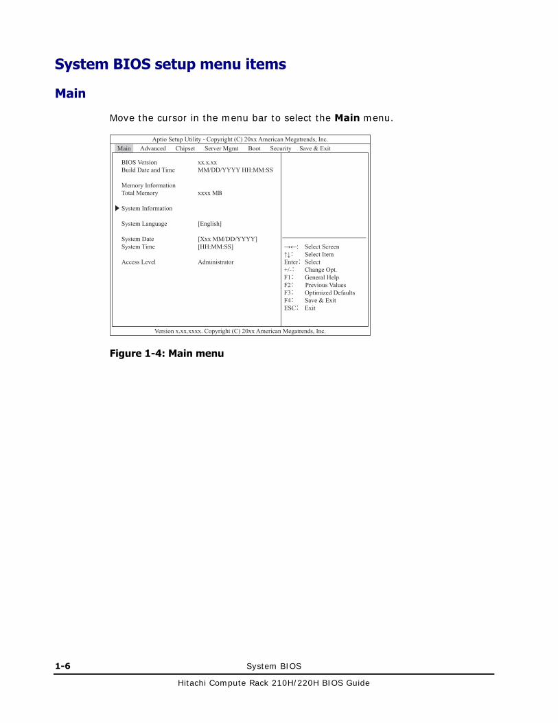
Main
Move the cursor in the menu bar to select the Main menu.
Figure 1-4: Main menu

System BIOS 1-7
Hitachi Compute Rack 210H/220H BIOS Guide
The following table shows description of menu items.
Table 1-2: Main menu items
Menu items Selection1 Description
BIOS Version - Displays the system BIOS version.
Build Date and Time - Displays the build data and time of the system BIOS.
Memory Information
Total Memory - Displays the total installed memory size.
System Information - Displays the System Information submenu.
See System Information for the details.
System Language [English] Specify the language used for the system BIOS setup menu.
System Date2 - Sets the local date of the system. Sets the date as MM/DD/YYYY.
System Time2 - Sets the local time of the system. Sets the time as HH:MM:SS in the form of 24 hours.
Access Level - Displays the user who is logging on to the system BIOS setup menu
Notes:
1 A value in square brackets, [ ], shows the default.
2 Use TAB, SHIFT + TAB, or Enter key to move the cursor inside System Time and System Date settings.
1-8 System BIOS
Hitachi Compute Rack 210H/220H BIOS Guide
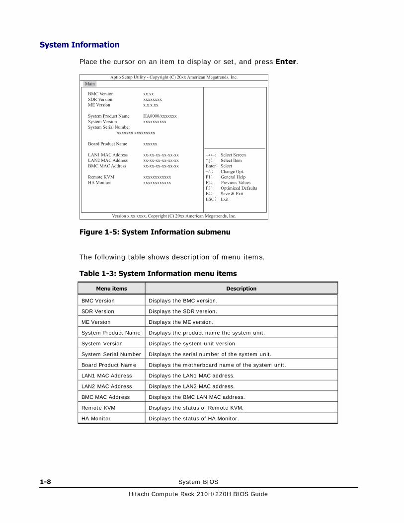
System Information
Place the cursor on an item to display or set, and press Enter.
Figure 1-5: System Information submenu
The following table shows description of menu items.
Table 1-3: System Information menu items
Menu items Description
BMC Version Displays the BMC version.
SDR Version Displays the SDR version.
ME Version Displays the ME version.
System Product Name Displays the product name the system unit.
System Version Displays the system unit version
System Serial Number Displays the serial number of the system unit.
Board Product Name Displays the motherboard name of the system unit.
LAN1 MAC Address Displays the LAN1 MAC address.
LAN2 MAC Address Displays the LAN2 MAC address.
BMC MAC Address Displays the BMC LAN MAC address.
Remote KVM Displays the status of Remote KVM.
HA Monitor Displays the status of HA Monitor.

System BIOS 1-9
Hitachi Compute Rack 210H/220H BIOS Guide
Advanced
Move the cursor in the menu bar to select the Advanced menu.
Figure 1-6: Advanced menu

1-10 System BIOS
Hitachi Compute Rack 210H/220H BIOS Guide
The following table shows description of menu items.
Table 1-4: Advanced menu items
Menu items Selection* Description
LAN1 PXE OpROM [Disabled]
Enabled
Sets a PXE boot from the onboard LAN1 controller
LAN2 PXE OpROM [Disabled]
Enabled
Sets a PXE boot from the onboard LAN2 controller
PCI Subsystem Settings - Displays the PCI Subsystem Settings submenu.
See PCI Subsystem Settings for the details.
Trusted Computing - Displays the Trusted Computing submenu.
See Trusted Computing for the details.
WHEA Configuration - Displays the WHEA Configuration submenu.
See WHEA Configuration for the details.
CPU Configuration - Displays the CPU Configuration submenu.
See CPU Configuration for the details.
Runntime Error Logging - Displays the Runntime Error Logging submenu.
See Runntime Error Logging for the details.
SATA Configuration - Displays the SATA Configuration submenu.
See SATA Configuration for the details.
Intel TXT(LT-SX) Configuration
- Displays the Intel TXT(LT-SX) Configuration submenu.
See Intel TXT(LT-SX) Configuration for the details.
USB Configuration - Displays the USB Configuration submenu.
See USB Configuration for the details.
Super IO Configuration - Displays the Super IO Configuration submenu.
See Super IO Configuration for the details.
Serial Port Console Redirection
Displays the Serial Port Console Redirection submenu.
See Serial Port Console Redirection for the details.
* A value in square brackets, [ ], shows the default.

System BIOS 1-11
Hitachi Compute Rack 210H/220H BIOS Guide
PCI Subsystem Settings
Place the cursor on an item to display or set, and press Enter.
Figure 1-7: PCI Subsystem Settings submenu
The following table shows description of menu items.
Table 1-5: PCI Subsystem Settings submenu items
Menu items Selection* Description
PCI ROM Priority [Legacy ROM]
EFI Compatible ROM
Sets the priority of the ROM on the PCI card.
No Snoop Disabled
[Enabled]
Sets a snoop function.
* A value in square brackets, [ ], shows the default.

1-12 System BIOS
Hitachi Compute Rack 210H/220H BIOS Guide
Trusted Computing
Place the cursor on an item to display or set, and press Enter.
Figure 1-8: Trusted Computing submenu
System BIOS 1-13
Hitachi Compute Rack 210H/220H BIOS Guide
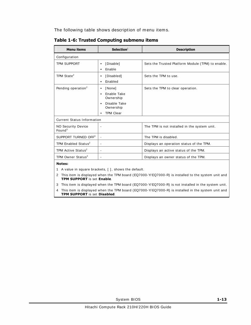
The following table shows description of menu items.
Table 1-6: Trusted Computing submenu items
Menu items Selection1 Description
Configuration
TPM SUPPORT [Disable]
Enable
Sets the Trusted Platform Module (TPM) to enable.
TPM State2 [Disabled]
Enabled
Sets the TPM to use.
Pending operation2 [None]
Enable Take Ownership
Disable Take Ownership
TPM Clear
Sets the TPM to clear operation.
Current Status Information
NO Security Device Found3
- The TPM is not installed in the system unit.
SUPPORT TURNED OFF4 - The TPM is disabled.
TPM Enabled Status2 - Displays an operation status of the TPM.
TPM Active Status2 - Displays an active status of the TPM.
TPM Owner Status2 - Displays an owner status of the TPM.
Notes:
1 A value in square brackets, [ ], shows the default.
2 This item is displayed when the TPM board (EQ7000-Y/EQ7000-R) is installed to the system unit and TPM SUPPORT is set Enable.
3 This item is displayed when the TPM board (EQ7000-Y/EQ7000-R) is not installed in the system unit.
4 This item is displayed when the TPM board (EQ7000-Y/EQ7000-R) is installed in the system unit and TPM SUPPORT is set Disabled.

1-14 System BIOS
Hitachi Compute Rack 210H/220H BIOS Guide
TPM SUPPORT setting
If you use Windows BitLocker function, perform the following procedures.
1. Change the setting of TPM SUPPORT to Enable.
2. Save settings and exit the system BIOS setup menu.
See Exiting system BIOS setup menu on page 1-56.
3. Restart the system unit, and then start the system BIOS setup menu.
See Starting system BIOS setup menu on page 1-3.
4. Change the setting of TPM State to Enabled.
5. Save settings and exit the system BIOS setup menu.
6. Restart the system unit, and then start the system BIOS setup menu.
7. Confirm the displaying of TPM Enabled Status and TPM Active Status is Enabled and Active.
Otherwise, leave the setting for TPM SUPPORT as disable (default).
When the system unit is restarted while TPM SUPPORT is enabled, TPM State may be enabled after starting the setup menu in the first time. In this case, also you should save the setting of setup menu.

System BIOS 1-15
Hitachi Compute Rack 210H/220H BIOS Guide
WHEA Configuration
Place the cursor on an item to display or set, and press Enter.
Figure 1-9: WHEA Configuration submenu
The following table shows description of menu items.
Table 1-7: WHEA Configuration submenu items
Menu items Selection* Description
WHEA Support [Disabled]
Enabled
Sets the Windows Hardware Error Architecture (WHEA) to enable.
* A value in square brackets, [ ], shows the default.

1-16 System BIOS
Hitachi Compute Rack 210H/220H BIOS Guide
CPU Configuration
Place the cursor on an item to display or set, and press Enter.
Figure 1-10: CPU Configuration submenu
Do not enable the settings of Discrete MTRR Allocation. If you change the settings, system BIOS may not start up.
If you change the setting of Intel Virtualization Technology, save the setting and turn off the power of the system unit to allow the new setting to take effect.

System BIOS 1-17
Hitachi Compute Rack 210H/220H BIOS Guide
The following table shows description of menu items.
Table 1-8: CPU Configuration submenu items
Menu items Selection1 Description
CPU Configuration
Socket 1 CPU Information
-
Socket 2 CPU Information2 3
-
Displays the Socket 1/2 CPU Information submenu.
See Socket 1 CPU Information for the details.
Hyper-threading4 Disabled
[Enabled]
Sets CPU Hyper Threading.
Active Processor Cores [All]
1, 2, 4, 6
Sets the number of running cores in the CPU package.
Execute Disable Bit Disabled
[Enabled]
With “Disable”, the response is always “0” for XD feature flag.
Hardware Prefetcher Disabled
[Enabled]
Sets CPU Data Prefetch.
Adjacent Cache Line Prefetch
Disabled
[Enabled]
Sets CPU cache Prefetch.
DCU Streamer Prefetcher
Disabled
[Enabled]
Sets DCU Streamer Prefetch function.
DCU IP Prefetcher Disabled
[Enabled]
Sets DCU IP Prefetch function.
Intel Virtualization Technology
Disabled
[Enabled]
Sets Vanderpool Technology, which is Intel's new virtualization technology.
Discrete MTRR Allocation
[Disabled]
Enabled
Sets discrete caching.
CPU Power Management Configuration
- Displays the CPU Power Management Configuration submenu.
See CPU Power Management Configuration for the details.
Notes:
1 A value in square brackets, [ ], shows the default.
2 This submenu items are same as the Socket 1 CPU Information submenu.
3 This item is displayed Socket 2 Not Present when the processor is not installed to the CPU socket 2.
4 This item is not displayed when the CPU installed in the system unit is not supporting the Hyper Threading function.

1-18 System BIOS
Hitachi Compute Rack 210H/220H BIOS Guide
Socket 1 CPU Information
Place the cursor on an item to display or set, and press Enter.
Figure 1-11: Socket 1 CPU Information submenu
The following table shows description of menu items.
Table 1-9: Socket 1 CPU Information submenu items
Menu items Description
Socket 1 CPU Information
Intel(R) Xeon® CPU @ x.xxGHz
Displays the type of CPU.
CPU Signature Displays the stepping of CPU.
Processor Core Displays the number of cores in the CPU package.

System BIOS 1-19
Hitachi Compute Rack 210H/220H BIOS Guide
CPU Power Management Configuration
Place the cursor on an item to display or set, and press Enter.
Figure 1-12: CPU Power Management Configuration submenu
Do not enable the settings of Frequency Floor Override. If you change the settings, the CPU power management may be adversely affected.

1-20 System BIOS
Hitachi Compute Rack 210H/220H BIOS Guide
The following table shows description of menu items.
Table 1-10: CPU Power Management Configuration submenu items
Menu items Selection1 Description
CPU Power Management Configuration
Power Technology Disabled
Energy Efficient
[Custom]
Sets CPU power technology function.
EIST2 Disabled
[Enabled]
Sets CPU EIST, which makes effect after the reboot.
Turbo Mode3 4 Disabled
[Enabled]
Sets CPU Turbo Mode, which makes effect after the reboot.
P-STATE Coordination3 [HW_ALL]
SW_ALL
SW_ANY
Sets the ACPI P-State coordination.
HW_ALL: Processor hardware is responsible. SW_ALL: OS Power Manager is responsible (all of logical processor). SW_ANY: OS Power Manager is responsible (any of logical processor).
CPU C3 Report2 [Disabled]
ACPI C-2
ACPI C-3
Sets CPU C2 or C3 Power States, which makes effect after the reboot.
CPU C6 report2 Disabled
[Enabled]
Sets CPU C6 Power States, which makes effect after the reboot.
CPU C7 report2 [Disabled]
Enabled
Sets CPU C6 Power States, which makes effect after the reboot.
Package C State limit2 C0
[C2]
C6
C7
No limit
Sets state for the C-State package limit.
Energy Performance Performance
[Balanced Performance]
Blanced Energy
Energy Efficient
Sets the policy of power consumption.
Frequency Floor Override
[Disabled]
Enabled
Sets the ACPI P-State limit.
Notes:
1 A value in square brackets, [ ], shows the default.
2 This item is displayed when Power Technology is set Custom.
3 This item is displayed when Power Technology is set Custom and EIST is set Enabled.
4 This item is not displayed when the CPU installed in the system unit is not supporting the Turbo Mode function.

System BIOS 1-21
Hitachi Compute Rack 210H/220H BIOS Guide
Runtime Error Logging
Place the cursor on an item to display or set, and press Enter.
Figure 1-13: Runtime Error Logging submenu
Do not disable the settings of Runtime Error Logging Support and PCI Error Logging Support. If you change the settings, system BIOS will not report error information.
The following table shows description of menu items.
Table 1-11: Runtime Error Logging submenu items
Menu items Selection1 Description
Runtime Error Logging Support
Disabled
[Enabled]
Sets runtime error logging function.
PCI Error Logging Support 2
Disabled
[Enabled]
Sets PCI error logging function.
Notes:
1 A value in square brackets, [ ], shows the default.
2 This item is displayed when Runtime Error Logging Support is set Enabled.

1-22 System BIOS
Hitachi Compute Rack 210H/220H BIOS Guide
SATA Configuration
Place the cursor on an item to display or set, and press Enter.
Figure 1-14: SATA Configuration submenu

System BIOS 1-23
Hitachi Compute Rack 210H/220H BIOS Guide
The following table shows description of menu items.
Table 1-12: SATA Configuration submenu items
Menu items Selection1 Description
SATA Configuration
SATA Port0
SATA Port1
SATA Port2
SATA Port3
SATA Port4
SATA Port5
- Displays the device information of connected to SATA port.
SATA Port4 will display installed DVD-ROM drive.
SATA Mode Disabled
IDE Mode
[AHCI Mode]
Sets SATA mode.
Serial-ATA Controller02 Disabled
Enhanced
[Compatible]
Sets SATA controller0 to enable.
Serial-ATA Controller12 Disabled
[Enabled]
Sets SATA controller1 to enable.
Notes:
1 A value in square brackets, [ ], shows the default.
2 This item is displayed when SATA Mode is set IDE Mode.
1-24 System BIOS
Hitachi Compute Rack 210H/220H BIOS Guide
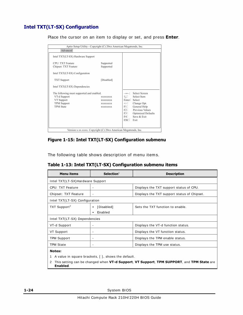
Intel TXT(LT-SX) Configuration
Place the cursor on an item to display or set, and press Enter.
Figure 1-15: Intel TXT(LT-SX) Configuration submenu
The following table shows description of menu items.
Table 1-13: Intel TXT(LT-SX) Configuration submenu items
Menu items Selection1 Description
Intel TXT(LT-SX)Hardware Support
CPU: TXT Feature - Displays the TXT support status of CPU.
Chipset: TXT Feature - Displays the TXT support status of Chipset.
Intel TXT(LT-SX) Configuration
TXT Support2 [Disabled]
Enabled
Sets the TXT function to enable.
Intel TXT(LT-SX) Dependencies
VT-d Support - Displays the VT-d function status.
VT Support - Displays the VT function status.
TPM Support - Displays the TPM enable status.
TPM State - Displays the TPM use status.
Notes:
1 A value in square brackets, [ ], shows the default.
2 This setting can be changed when VT-d Support, VT Support, TPM SUPPORT, and TPM State are Enabled.

System BIOS 1-25
Hitachi Compute Rack 210H/220H BIOS Guide
USB Configuration
Place the cursor on an item to display or set, and press Enter.
Figure 1-16: USB Configuration submenu

1-26 System BIOS
Hitachi Compute Rack 210H/220H BIOS Guide
The following table shows description of menu items.
Table 1-14: USB Configuration submenu items
Menu items Selection1 Description
USB Configuration
USB Device - Displays the detected USB devices.
Legacy USB Support [Enabled]
Disabled
Auto
Sets USB devices to use in legacy mode.
EHCI Hand-off [Disabled]
Enabled
Sets USB legacy mode to disabled.
Port 60/64 Emulation Disabled
[Enabled]
Sets PS/2 keyboard/mouse emulation.
USB hardware delays and time-outs:
USB transfer time-out 1 sec
5 sec
10 sec
[20 sec]
Sets USB transfer time-out.
Device reset time-out 10 sec
[20 sec]
30 sec
40 sec
Sets USB device reset time-out.
Device power-up delay [Auto]
Manual
Sets delay of USB device powering-up.
Device power-up delay in seconds2
[5]
1-40
Sets delay time of USB device powering-up.
Mass Storage Devices:3
xxxxxxxxxxxxxxx3 [Auto]
Floppy
Forced FDD
Hard Disk
CD-ROM
Sets the emulation mode of a USB mass storage device.
Notes:
1 A value in square brackets, [ ], shows the default.
2 This item is displayed when Device power-up delay is set Manual, but not supported.
3 This item is displayed when a USB mass storage device is connected to the system unit.

System BIOS 1-27
Hitachi Compute Rack 210H/220H BIOS Guide
Super IO Configuration
Place the cursor on an item to display or set, and press Enter.
Figure 1-17: Super IO Configuration submenu
The following table shows description of menu items.
Table 1-15: Super IO Configuration submenu items
Menu items Description
Super IO Configuration
Super IO Chip Displays the super I/O device..
Serial Port 0 Configuration
Serial Port 1 Configuration*
Displays the Serial Port 0/1 Configuration submenu.
See Serial Port 0 Configuration for the details.
* This submenu items are same as the Serial Port 0 Configuration submenu.

1-28 System BIOS
Hitachi Compute Rack 210H/220H BIOS Guide
Serial Port 0 Configuration
Place the cursor on an item to display or set, and press Enter.
Figure 1-18: Serial Port 0 Configuration submenu
The following table shows description of menu items.
Table 1-16: Serial Port 0 Configuration submenu items
Menu items Selection1 Description
Serial Port 0 Configuration
Serial Port2 Disabled
[Enabled]
Sets serial poor t0 to enable.
Device Settings3 - Displays serial port 0 setting.
Change Settings3 [Auto]
IO=3F8h;IRQ=4;
IO=3F8h;IRQ=3,4, 5,6,7,10,11,12;
IO=2F8h;IRQ=3,4, 5,6,7,10,11,12;
IO=3E8h;IRQ=3,4, 5,6,7,10,11,12;
IO=2E8h;IRQ=3,4, 5,6,7,10,11,12;
Sets I/O and IRQ to serial port 0.
Notes:
1 A value in square brackets, [ ], shows the default.
2 This item is set as Disabled in the Serial Port 1 Configuration submenu.
3 This item is displayed when Serial Port is set Enabled.

System BIOS 1-29
Hitachi Compute Rack 210H/220H BIOS Guide
Serial Port Console Redirection
Place the cursor on an item to display or set, and press Enter.
Figure 1-19: Serial Port Console Redirection submenu
Do not enable the settings of Serial Port Console Redirection items. This function is not supported by Hitachi Compute Rack System.

1-30 System BIOS
Hitachi Compute Rack 210H/220H BIOS Guide
The following table shows description of menu items.
Table 1-17: Serial Port Console Redirection submenu items
Menu items Selection* Description
COM0
Console Redirection [Disabled]
Enabled
Sets console redirection function to enable.
Console Redirection Settings
- Displays the Console Redirection Settings submenu.
This submenu can not change settings because Console Redirection is Disabled.
Serial Port for Out-Band Management/Windows Emergency Management Services (EMS)
Console Redirection [Disabled]
Enabled
Sets console redirection function to enable.
Console Redirection Settings
- Displays the Console Redirection Settings submenu.
This submenu can not change settings because Console Redirection is Disabled.
* A value in square brackets, [ ], shows the default.

System BIOS 1-31
Hitachi Compute Rack 210H/220H BIOS Guide
Chipset
Move the cursor in the menu bar to select the Chipset menu.
Figure 1-20: Chipset menu
The following table shows description of menu items in the left pane of window.
Table 1-18: Chipset menu items
Menu items Description
North Bridge Displays the North Bridge submenu.
See North Bridge for the details.
South Bridge Displays the South Bridge submenu.
See South Bridge for the details.

1-32 System BIOS
Hitachi Compute Rack 210H/220H BIOS Guide
North Bridge
Place the cursor on an item to display or set, and press Enter.
Figure 1-21: North Bridge submenu
If you change the setting of NUMA, save the setting and turn off the power of the system unit to allow the new setting to take effect.
Do not change the settings of DDR Speed. If you change the settings, the system unit may not operate properly.
Do not change the settings of Channel Interleaving and Rank Interleaving. If you change the settings, memory performance may be degraded.

System BIOS 1-33
Hitachi Compute Rack 210H/220H BIOS Guide
The following table shows description of menu items.
Table 1-19: North Bridge submenu items
Menu items Selection1 Description
IOH Configuration - Displays the IOH Configuration submenu.
See IOH Configuration for the details.
QPI Configuration - Displays the QPI Configuration submenu.
See QPI Configuration for the details.
Memory Configuration
Total Memory2 - Displays the total memory size.
Current Memory Mode - Displays the current memory mode.
Current Memory Speed - Displays current memory speed.
Current DDR Voltage - Displays current voltage of DIMM.
Mirroring - Displays whether mirror mode is possible on the installed memory configuration.
Sparing - Displays whether spare mode is possible on the installed memory configuration.
Memory Retest No
[Yes]
Sets the memory information to clear.
If you want to clear the error information of disabled memory and clear the disabled state, set Yes after you replace the DIMM.
Memory Mode [Independent]
Mirroring
Lock Step
Sparing
Selects the memory operating mode.
Numa3 Disabled
[Enabled]
Sets Non-Uniform Memory Access (NUMA) to enable.
DDR Speed [Auto]
Force DDR3 800
Force DDR3 1066
Force DDR3 1333
Force DDR3 1600
Sets clock speed of DDR.
DDR Voltage [Auto]
1.5V
Sets voltage of DIMM.
Channel Interleaving [Auto]
1-way
2-way
3-way
4-way
Sets the memory channel interleaving.
Rank Interleaving [Auto]
1-way
2-way
4-way
8-way
Sets the rank of memory interleaving.

1-34 System BIOS
Hitachi Compute Rack 210H/220H BIOS Guide
Menu items Selection1 Description
Patrol Scrub Disabled
[Enabled]
Sets the patrol scrubbing which proactively searches the memory to repair correctable errors.
Data Scrambling Disabled
[Enabled]
Sets the memory data scrambling.
Device Tagging [Disabled]
Enabled
Set the device tagging on DIMM.
DIMM Information - Displays the DIMM Information submenu.
See DIMM Information for the details.
Notes:
1 A value in square brackets, [ ], shows the default.
2 If Memory Mode is set Mirroring, half of the installed memory is used for mirroring. The capacity displayed in Total Memory is half of the installed memory size. If Memory Mode is set Sparing, for each channel, one rank from the installed DIMMs are used as spare memory. Depending on whether the installed DIMMs are single-rank or dual-rank, the capacity displayed in Total Memory is different. The capacity displayed Total Memory is as follows:
- If single-rank DIMMs are installed: 1/2 (2DIMM per channel) or 2/3 (3DIMM per Channel) of the installed memory size.
- If dual-rank DIMMs are installed: 3/4 (2DIMM per Channel) or 5/6 (3DIMM per Channel) of the installed memory size.
3 This item is displayed when installing two CPUs in the system unit.
Memory Mode
In order to enable memory redundancy, you can set the memory mirroring function, the lock step function or the online spare memory function.
If you use memory mirroring, set Mirroring.
If you use memory lock step, set Lock Step.
If you use online spare memory, set Sparing.
When you use memory mirroring, memory lock step, or online spare memory, you need to understand the restrictions on the configuration of memory boards. See Hitachi Compute Rack 210H User’s Guide or Hitachi Compute Rack 220H User’s Guide.
DDR Voltage
The memory 1600 RDIMM should satisfy the following conditions to perform as high as 1600 MHz when the memory 1600 RDIMM is mounted in the system unit.
Changed from Auto to 1.5V for the configuration of DDR Voltage.
Xeon processer E5-2670 or E5-2690 should be mounted, and the number of mounted DIMM should be 1DPC* or 2DPC*.
* DPC (DIMM per channel) is the number of DIMM per channel.
– 1DPC: Less than or equal to 1 DIMM is mounted in each channel.
– 2DPC: 2 DIMMs are mounted in even one of channels.
– 3DPC: 3 DIMMs are mounted in even one of channels.

System BIOS 1-35
Hitachi Compute Rack 210H/220H BIOS Guide
Device Tagging
You can use device tagging, where redundancy is enabled at the DRAM chip level so that the system unit can avoid system down and can continue operation even when one DRAM chip on the DIMM fails. Device tagging is not operated when you set Memory Mode to Mirroring, Lock Step, or Sparing. If you use device tagging, set Memory Mode to Independent.

1-36 System BIOS
Hitachi Compute Rack 210H/220H BIOS Guide
IOH Configuration
Place the cursor on an item to display or set, and press Enter.
Figure 1-22: IOH Configuration submenu
The following table shows description of menu items.
Table 1-20: IOH Configuration submenu items
Menu items Selection* Description
Intel(R) VT for Directed I/O Configuration
- Displays the Intel(R) VT for Directed I/O Configuration submenu.
See Intel(R) VT for Directed I/O Configuration for the details.
Intel(R) I/OAT [Disabled]
Enabled
Sets Intel I/O Acceleration Technology to enable.
DCA Support Disabled
[Enabled]
Sets QPI DCA to enable..
MMIOH Size [64G]
1G, 2G, 4G, 8G, 16G, 32G, 128G
Sets the size of the memory-mapped I/O above 4GB address.
CPU PCI Express L1 Disabled
[Enabled]
Sets the power saving function (L1) by the CPU.
* A value in square brackets, [ ], shows the default.

System BIOS 1-37
Hitachi Compute Rack 210H/220H BIOS Guide
Intel(R) VT for Directed I/O Configuration
Place the cursor on an item to display or set, and press Enter.
Figure 1-23: Intel(R) VT for Directed I/O Configuration submenu
The following table shows description of menu items.
Table 1-21: Intel(R) VT for Directed I/O Configuration submenu items
Menu items Selection1 Description
Intel(R) VT-d Disabled
[Enabled]
Sets Intel VT-d to enable.
Coherency Support2 [Disabled]
Enabled
Sets coherency mode.
ATS Support2 Disabled
[Enabled]
Sets the address translation service (ATS) to enable.
Notes:
1 A value in square brackets, [ ], shows the default.
2 This item is displayed when Intel(R) VT-d is set Enabled.

1-38 System BIOS
Hitachi Compute Rack 210H/220H BIOS Guide
QPI Configuration
Place the cursor on an item to display or set, and press Enter.
Figure 1-24: QPI Configuration submenu

System BIOS 1-39
Hitachi Compute Rack 210H/220H BIOS Guide
The following table shows description of menu items.
Table 1-22: QPI Configuration submenu items
Menu items Selection1 Description
Current QPI Link Speed - Displays current QPI link mode.
Current QPI Link Freq2 - Displays current QPI link speed.
Isoc Disabled
[Enabled]
Sets QPI isochronous.
QPI Link Speed Mode [Fast]
Slow
Sets QPI link mode.
QPI Link Frequency Select
[Auto]
6.4 GT/s
7.2 GT/s
8.0 GT/s
Sets QPI link speed.
QPI Link0p [Disabled]
Enabled
Sets QPI power saving mode (L0p) to enable.
QPI Link1 [Disabled]
Enabled
Sets QPI power saving mode (L1) to enable.
Alternate RTID [Disabled]
Enabled
Sets the transaction ID to enable.
Notes:
1 A value in square brackets, [ ], shows the default.
2 This item is displayed Unknown when installing one CPU in the system unit.

1-40 System BIOS
Hitachi Compute Rack 210H/220H BIOS Guide
DIMM Information
Place the cursor on an item to display or set, and press Enter.
Figure 1-25: DIMM Information submenu
System BIOS 1-41
Hitachi Compute Rack 210H/220H BIOS Guide
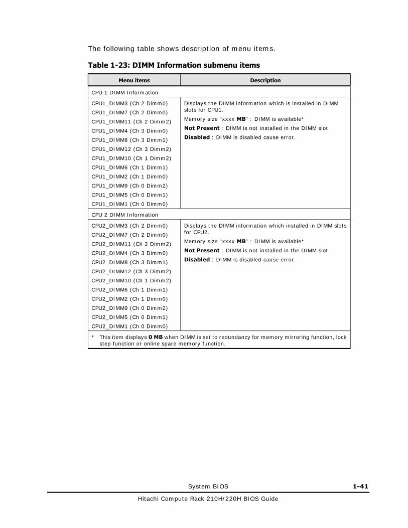
The following table shows description of menu items.
Table 1-23: DIMM Information submenu items
Menu items Description
CPU 1 DIMM Information
CPU1_DIMM3 (Ch 2 Dimm0)
CPU1_DIMM7 (Ch 2 Dimm0)
CPU1_DIMM11 (Ch 2 Dimm2)
CPU1_DIMM4 (Ch 3 Dimm0)
CPU1_DIMM8 (Ch 3 Dimm1)
CPU1_DIMM12 (Ch 3 Dimm2)
CPU1_DIMM10 (Ch 1 Dimm2)
CPU1_DIMM6 (Ch 1 Dimm1)
CPU1_DIMM2 (Ch 1 Dimm0)
CPU1_DIMM9 (Ch 0 Dimm2)
CPU1_DIMM5 (Ch 0 Dimm1)
CPU1_DIMM1 (Ch 0 Dimm0)
Displays the DIMM information which is installed in DIMM slots for CPU1.
Memory size "xxxx MB" : DIMM is available*
Not Present : DIMM is not installed in the DIMM slot
Disabled : DIMM is disabled cause error.
CPU 2 DIMM Information
CPU2_DIMM3 (Ch 2 Dimm0)
CPU2_DIMM7 (Ch 2 Dimm0)
CPU2_DIMM11 (Ch 2 Dimm2)
CPU2_DIMM4 (Ch 3 Dimm0)
CPU2_DIMM8 (Ch 3 Dimm1)
CPU2_DIMM12 (Ch 3 Dimm2)
CPU2_DIMM10 (Ch 1 Dimm2)
CPU2_DIMM6 (Ch 1 Dimm1)
CPU2_DIMM2 (Ch 1 Dimm0)
CPU2_DIMM9 (Ch 0 Dimm2)
CPU2_DIMM5 (Ch 0 Dimm1)
CPU2_DIMM1 (Ch 0 Dimm0)
Displays the DIMM information which installed in DIMM slots for CPU2.
Memory size "xxxx MB" : DIMM is available*
Not Present : DIMM is not installed in the DIMM slot
Disabled : DIMM is disabled cause error.
* This item displays 0 MB when DIMM is set to redundancy for memory mirroring function, lock step function or online spare memory function.

1-42 System BIOS
Hitachi Compute Rack 210H/220H BIOS Guide
South Bridge
Place the cursor on an item to display or set, and press Enter.
Figure 1-26: South Bridge submenu
The following table shows description of menu items.
Table 1-24: South Bridge submenu items
Menu items Selection* Description
Stepping - Displays the stepping of the chipset.
Restore AC Power Loss Power Off
Power On
[Last State]
Selects a status after restore AC power loss.
High Precision Event Timer Configuration
High Precision Timer Disabled
[Enabled]
Sets the high precision event timer.
PCI Express Ports Configuration
- Displays the PCI Express Ports Configuration submenu.
See PCI Express Ports Configuration for the details.
USB Configuration - Displays the USB Configuration submenu.
See USB Configuration for the details.
* A value in square brackets, [ ], shows the default.

System BIOS 1-43
Hitachi Compute Rack 210H/220H BIOS Guide
PCI Express Ports Configuration
Place the cursor on an item to display or set, and press Enter.
Figure 1-27: PCI Express Ports Configuration submenu
Do not disable the settings of Onboard VGA. If you change this, the video signals are not output from the system unit.
The following table shows description of menu items.
Table 1-25: PCI Express Ports Configuration submenu items
Menu items Selection* Description
PCI Express Ports Configuration
Onboard VGA Disabled
[Enabled]
Sets the onboard VGA.
PCH PCI Express L1 [Enabled]
Disabled
Sets power saving function (L1) by the PCH.
DMI Vc1 Control Disabled
[Enabled]
Sets virtual channel (Vc1) on the DMI bus to enable.
DMI Vcp Control Disabled
[Enabled]
Sets virtual channel (Vcp) on the DMI bus to enable.
DMI Vcm Control Disabled
[Enabled]
Sets virtual channel (Vcm) on the DMI bus to enable.
* A value in square brackets, [ ], shows the default.

1-44 System BIOS
Hitachi Compute Rack 210H/220H BIOS Guide
USB Configuration
Place the cursor on an item to display or set, and press Enter.
Figure 1-28: USB Configuration submenu
Do not disable the all settings of USB Configuration. If you change these, you cannot use a keyboard connected to the system unit.
The following table shows description of menu items.
Table 1-26: USB Configuration submenu items
Menu items Selection* Description
USB Configuration
USB Front Port Disabled
[Enabled]
Sets the front USB port to enable.
USB Rear Port Disabled
[Enabled]
Sets the rear USB port to enable.
USB BMC Port Disabled
[Enabled]
Sets the BMC USB port to enable.
USB Internal Port Disabled
[Enabled]
Sets the internal USB port to enable.
* A value in square brackets, [ ], shows the default.

System BIOS 1-45
Hitachi Compute Rack 210H/220H BIOS Guide
ServerMgmt
Move the cursor in the menu bar to select the ServerMgmt menu.
Figure 1-29: ServerMgmt menu
1-46 System BIOS
Hitachi Compute Rack 210H/220H BIOS Guide
The following table shows description of menu items.
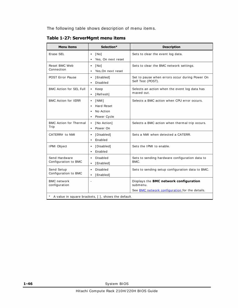
Table 1-27: ServerMgmt menu items
Menu items Selection* Description
Erase SEL [No]
Yes, On next reset
Sets to clear the event log data.
Reset BMC Web Connection
[No]
Yes,On next reset
Sets to clear the BMC network settings.
POST Error Pause [Enabled]
Disabled
Set to pause when errors occur during Power On Self Test (POST).
BMC Action for SEL Full Keep
[Refresh]
Selects an action when the event log data has maxed out.
BMC Action for IERR [NMI]
Hard Reset
No Action
Power Cycle
Selects a BMC action when CPU error occurs.
BMC Action for Thermal Trip
[No Action]
Power On
Selects a BMC action when thermal trip occurs.
CATERR# to NMI [Disabled]
Enabled
Sets a NMI when detected a CATERR.
IPMI Object [Disabled]
Enabled
Sets the IPMI to enable.
Send Hardware Configuration to BMC
Disabled
[Enabled]
Sets to sending hardware configuration data to BMC.
Send Setup Configuration to BMC
Disabled
[Enabled]
Sets to sending setup configuration data to BMC.
BMC network configuration
- Displays the BMC network configuration submenu.
See BMC network configuration for the details.
* A value in square brackets, [ ], shows the default.
System BIOS 1-47
Hitachi Compute Rack 210H/220H BIOS Guide
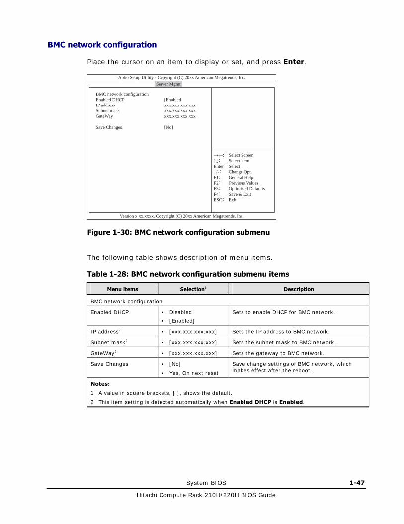
BMC network configuration
Place the cursor on an item to display or set, and press Enter.
BMC network configurationEnabled DHCPIP addressSubnet maskGateWay
Save Changes
[Enabled]xxx.xxx.xxx.xxxxxx.xxx.xxx.xxxxxx.xxx.xxx.xxx
[No]
→←: Select Screen↑↓: Select ItemEnter: Select+/-: Change Opt.F1: General HelpF2: Previous Values F3: Optimized DefaultsF4: Save & ExitESC: Exit
Aptio Setup Utility - Copyright (C) 20xx American Megatrends, Inc.
Version x.xx.xxxx. Copyright (C) 20xx American Megatrends, Inc.
Main Advanced Chipset Server Mgmt Boot Security Save & Exit
Figure 1-30: BMC network configuration submenu
The following table shows description of menu items.
Table 1-28: BMC network configuration submenu items
Menu items Selection1 Description
BMC network configuration
Enabled DHCP Disabled
[Enabled]
Sets to enable DHCP for BMC network.
IP address2 [xxx.xxx.xxx.xxx] Sets the IP address to BMC network.
Subnet mask2 [xxx.xxx.xxx.xxx] Sets the subnet mask to BMC network.
GateWay2 [xxx.xxx.xxx.xxx] Sets the gateway to BMC network.
Save Changes [No]
Yes, On next reset
Save change settings of BMC network, which makes effect after the reboot.
Notes:
1 A value in square brackets, [ ], shows the default.
2 This item setting is detected automatically when Enabled DHCP is Enabled.

1-48 System BIOS
Hitachi Compute Rack 210H/220H BIOS Guide
When the BMC network setting is changed and saved, the reflecting time may take time for several tens of seconds until the setting is reflected to the BMC. The BMC network can not be connected in this time. The old value before setting may be displayed when confirming the BMC network setting with the system BIOS setup menu. In this case, restart the system unit again. Check the BMC network setting and configuration if BMC network can not be connected after restarting.
Setup for the BMC network settings is necessary when the remote management function is used. See Hitachi Compute Rack 210H/220H Remote Management User’s Guide.
The DHCP address has lease period. We recommend that only using DHCP when setting up the system unit. Set disabled DHCP after setting up the system unit, and then changes a static IP address.

System BIOS 1-49
Hitachi Compute Rack 210H/220H BIOS Guide
Boot
Move the cursor in the menu bar to select the Boot menu.
Figure 1-31: Boot menu

1-50 System BIOS
Hitachi Compute Rack 210H/220H BIOS Guide
The following table shows description of menu items.
Table 1-29: Boot menu items
Menu items Selection1 Description
Boot Configuration
Setup Prompt Timeout [1]
1-65535
Sets the display time of the setup prompts during Power On Self Test (POST).
This item setting must be 1 to 10.
Bootup NumLock State [On]
Off
Sets the numlock state at boot up.
Quiet Boot [Disabled]
Enabled
Sets whether to suppress messages during boot up.
Boot Option Priorities Clear
[No]
Yes
Sets to clear the boot device priority settings.
Boot Option Priorities2
Boot Option #1 [P4: xxxxxxxx ...]
Boot Option #2 [(Bus xx Dev xx) PCI ...]
Boot Option #3 [Built-in EFI Shell]
Sets priorities of the boot devices.
CD/DVD ROM Drive BBS Priorities3
- Displays the CD/DVD ROM Drive BBS Priorities submenu.
See CD/DVD ROM Drive BBS Priorities for the details.
Hard Drive BBS Priorities3
- Displays the Hard Drive BBS Priorities submenu.
See Hard Drive BBS Priorities for the details.
Network Device BBS Priorities4
- Displays the Network Device BBS Priorities submenu.
Floppy Drive BBS Priorities3 5
- Displays the Floppy Drive BBS Priorities submenu.
Notes:
1 A value in square brackets, [ ], shows the default.
2 If you set Advanced>LAN1 PXE OpROM or LAN2 PXE OpROM, PXE boot is enabled. BRCM MBA Slot 0x0X … item is displayed in the Boot Option Priorities when PXE boot is enabled.
3 These items’ display order is changed by configuration of the system unit.
4 This item is displayed when you set Advanced>LAN1 PXE OpROM or LAN2 PXE OpROM, PXE boot is enabled.
5 This item is displayed when you connect an external floppy disk drive to the system unit.

System BIOS 1-51
Hitachi Compute Rack 210H/220H BIOS Guide
Boot from Remote Console virtual device
When the Remote Console is enabled, the remote CD-ROM drive is displayed as HITACHI Remote CD/DVD x.xx in the Network Device BBS Priorities submenu and the remote floppy disk drive is displayed as HITACHI Remote FD x.xx in the Floppy Drive BBS Priorities submenu.
If you want to boot from the remote CD-ROM drive or the remote floppy drive on the Remote Console, change the priority for the HITACHI Remote CD/DVD x.xx or HITACHI Remote FD x.xx accordingly.
1-52 System BIOS
Hitachi Compute Rack 210H/220H BIOS Guide
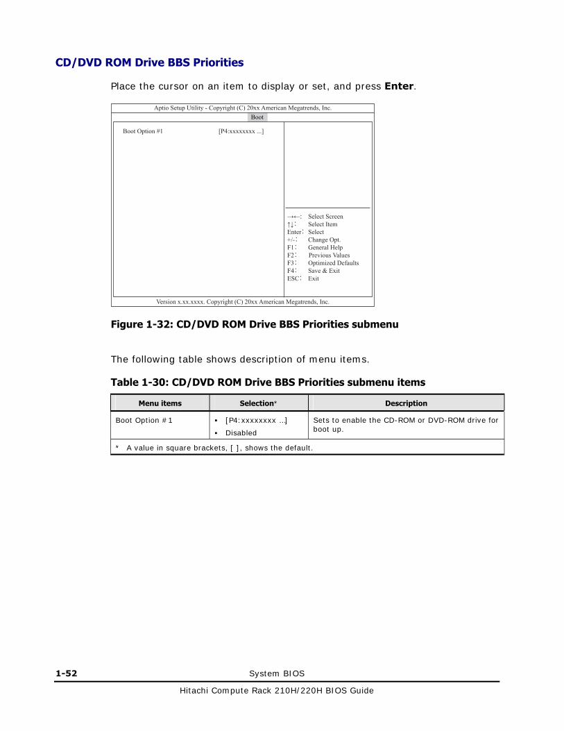
CD/DVD ROM Drive BBS Priorities
Place the cursor on an item to display or set, and press Enter.
Figure 1-32: CD/DVD ROM Drive BBS Priorities submenu
The following table shows description of menu items.
Table 1-30: CD/DVD ROM Drive BBS Priorities submenu items
Menu items Selection* Description
Boot Option #1 [P4:xxxxxxxx …]
Disabled
Sets to enable the CD-ROM or DVD-ROM drive for boot up.
* A value in square brackets, [ ], shows the default.

System BIOS 1-53
Hitachi Compute Rack 210H/220H BIOS Guide
Hard Drive BBS Priorities
Place the cursor on an item to display or set, and press Enter.
Figure 1-33: Hard Drive BBS Priorities submenu
The following table shows description of menu items.
Table 1-31: Hard Drive BBS Priorities submenu items
Menu items Selection* Description
Boot Option #1 [(Bus xx Dev xx)PCI RAID Adapter]
Disabled
Sets to enable the HDD for boot up.
* A value in square brackets, [ ], shows the default.

1-54 System BIOS
Hitachi Compute Rack 210H/220H BIOS Guide
Security
Move the cursor in the menu bar to select the Security menu.
This system does not support password setting in the Security menu. If you enter a password and then you forget the password, the system unit can no longer be used and must be repaired.
Figure 1-34: Security menu
The following table shows description of menu items.
Table 1-32: Security menu items
Menu items Selection Description
Password Description
Administrator
Password
- Sets an administrator password.
User Password - Sets a user password.
System BIOS 1-55
Hitachi Compute Rack 210H/220H BIOS Guide
Save & Exit
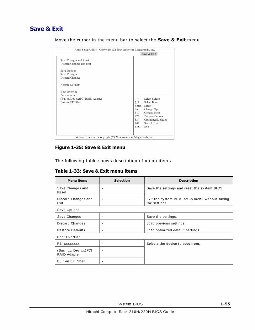
Move the cursor in the menu bar to select the Save & Exit menu.
Figure 1-35: Save & Exit menu
The following table shows description of menu items.
Table 1-33: Save & Exit menu items
Menu items Selection Description
Save Changes and Reset
- Save the settings and reset the system BIOS.
Discard Changes and Exit
- Exit the system BIOS setup menu without saving the settings.
Save Options
Save Changes - Save the settings.
Discard Changes - Load previous settings.
Restore Defaults - Load optimized default settings.
Boot Override
P4: xxxxxxxx -
(Bus xx Dev xx)PCI RAID Adapter
-
Built-in EFI Shell -
Selects the device to boot from.

1-56 System BIOS
Hitachi Compute Rack 210H/220H BIOS Guide
Exiting system BIOS setup menu 1. Press F4 key.
A confirmation message to save the settings is displayed.
Figure 1-36: Save & reset window
2. Select Yes by moving cursor, and then press Enter key.
The settings in the system BIOS setup menu are saved. The system unit will be restarted.
If you want to go back to the menu, select No and press ENTER key.

2
MegaRAID WebBIOS 2-1
Hitachi Compute Rack 210H/220H BIOS Guide
MegaRAID WebBIOS
This chapter describes the functionality of MegaRAID WebBIOS.
Configuration of MegaRAID WebBIOS
Disk array utility for the system
Type of RAID controllers
Starting MegaRAID WebBIOS
Operation for MegaRAID WebBIOS
Window configuration of MegaRAID WebBIOS
MegaRAID WebBIOS menu items
Building and editing virtual drives
Disk with foreign configuration
Exiting MegaRAID WebBIOS
Status

2-2 MegaRAID WebBIOS
Hitachi Compute Rack 210H/220H BIOS Guide
Configuration of MegaRAID WebBIOS
This section describes the MegaRAID WebBIOS configuration. See the following chart.
Figure 2-1: MegaRAID WebBIOS configuration
Advanced Software Options
Controller Selection
Main menu
Controller Properties
Scan Devices
Virtual Drives
Drives
Configuration Wizard
Physical View/Logical View
Events
End
Controller Selection
Exit
Start

MegaRAID WebBIOS 2-3
Hitachi Compute Rack 210H/220H BIOS Guide
Disk array utility for the system
The system equipment can set a disk array using the utility “MegaRAID WebBIOS”.
Under normal operation, you do not need to change the settings.
Setting is required only if you need to change the system configuration, for example, when you have changed disks.
Operate MegaRAID WebBIOS in accordance with descriptions in this manual. Otherwise, it may not work properly. Do not execute the operation other than described in this manual.
Connect a mouse to the system unit before starting MegaRAID WebBIOS.
Type of RAID controllers
Two types of RAID controller are installed to system units. Those Two types differ in whether the controller is with or without a cache backup module. In the MegaRAID WebBIOS menus, the controller types are displayed below:
RAID controller with cache backup module: LSI MegaRAID SAS 9266-8i
RAID controller without cache backup module: LSI MegaRAID SAS 9267-8i
Note that in the following description, some setup items and setup steps may differ depending on the type of the RAID controller.
2-4 MegaRAID WebBIOS
Hitachi Compute Rack 210H/220H BIOS Guide
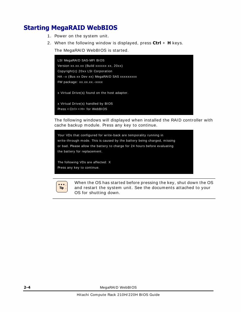
Starting MegaRAID WebBIOS 1. Power on the system unit.
2. When the following window is displayed, press Ctrl + H keys.
The MegaRAID WebBIOS is started.
The following windows will displayed when installed the RAID controller with cache backup module. Press any key to continue.
When the OS has started before pressing the key, shut down the OS and restart the system unit. See the documents attached to your OS for shutting down.
Your VDs that configured for write-back are temporality running in
write-through mode. This is caused by the battery being charged, missing
or bad. Please allow the battery to charge for 24 hours before evaluating
the battery for replacement.
The following VDs are affected: X
Press any key to continue.
LSI MegaRAID SAS-MFI BIOS
Version xx.xx.xx (Build xxxxxx xx, 20xx)
Copyright(c) 20xx LSI Corporation
HA –x (Bus xx Dev xx) MegaRAID SAS xxxxxxxxx
FW package: xx.xx.xx.-xxxx
x Virtual Drive(s) found on the host adapter.
x Virtual Drive(s) handled by BIOS
Press <Ctrl><H> for WebBIOS

MegaRAID WebBIOS 2-5
Hitachi Compute Rack 210H/220H BIOS Guide
3. The MegaRAID WebBIOS is started and Adapter Selection is displayed.
4. Press Ctrl key at the left side of the keyboard once.
If Ctrl key at the left side of the keyboard is not pressed, your keyboard and mouse may not operate properly. If the keyboard or mouse is not available when you operate MegaRAID WebBIOS, press Ctrl key at the left side of the keyboard once.
5. Press Enter key once.
The main menu is displayed.

2-6 MegaRAID WebBIOS
Hitachi Compute Rack 210H/220H BIOS Guide
If you do not press Enter key, the mouse will not work properly.
If a disk is different from the disk array configuration recorded in the RAID controller, the following window is displayed. See Disk with foreign configuration when the following window is displayed.

MegaRAID WebBIOS 2-7
Hitachi Compute Rack 210H/220H BIOS Guide
Operation for MegaRAID WebBIOS
For MegaRAID WebBIOS, you can set individual items by using the following keys and mouse. Connect a mouse to the remote console before starting MegaRAID WebBIOS.
Table 2-1: Keys and mouse
Key/mouse Operation
Mouse Moves the cursor.
Mouse – left button Selects an item that the mouse cursor is placed on.
Moves the cursor to an item to which the mouse cursor points.
Selects a disk array or physical disk.
[0] to [9] Enters numerical values.
[Ctrl] Selects multiple disk arrays or disks.
[Delete], [Back Space] Deletes an entered value.
Window configuration of MegaRAID WebBIOS
The window configuration of MegaRAID WebBIOS is shown below.
Figure 2-2: MegaRAID WebBIOS window components
1
2
3

2-8 MegaRAID WebBIOS
Hitachi Compute Rack 210H/220H BIOS Guide
1. Menu icon
Table 2-3: Menu icons
Icon at the upper left on the window
Operation of icon
Return to the main menu.
Return to the previous window.
Finish the utility.
Temporarily stop ringing the buzzer on the disk array controller board. *
Display the version of MegaRAID Web BIOS.
*This function is not supported.
2. Menu items
Menu items for MegaRAID WebBIOS are displayed. Click each item to go to the respective menu window.
3. Logical View/Physical View
Virtual drives or drives connected to the RAID controller are displayed.
Click a drive from drives displayed in Logical View or Physical View, and the same window is displayed as one when you select Drives > Properties from the menu.
Select a virtual drive from drives displayed in Logical View, and the same window is displayed as the one when you click Virtual Drives > Properties from the menu.
If not all capacity of the Drive Group is not used, Total Free Capacity is displayed. When Total Free Capacity is displayed, you can add an additional virtual drive to the Drive Group. Note that the RAID level of the new virtual drive has to be the same as the RAID level of the virtual drives already constructed in the Drive Group.

MegaRAID WebBIOS 2-9
Hitachi Compute Rack 210H/220H BIOS Guide
MegaRAID WebBIOS menu items
This section describes the setting items and values for MegaRAID WebBIOS.
In the table, the underlined values are default values. Those values in squared brackets, [ ], are recommended values.
Example:
[Enabled] / Disabled: "Enabled" is the default and also recommended value.
[Enabled] / Disabled: "Disabled" is the default value; and "Enabled" is the recommended value, which requires the change.
Unless otherwise specified, use the recommended values for all setting items. If you set non-recommended values, the equipment would not be supported and might not operate properly.

2-10 MegaRAID WebBIOS
Hitachi Compute Rack 210H/220H BIOS Guide
Main menu
Start MegaRAID WebBIOS, and the following main menu is displayed.
The following table shows description of menu items in the left side of window.
Table 2-4: Main menu items
Menu items Description
Advanced Software Options Sets expansion functions
Controller Selection* Returns to the Controller Selection window
Controller Properties Displays and sets the hardware information on the disk array controller board
Scan Devices Scans the installed devices
Virtual Drives Displays and sets the virtual drive (logical drive) information
Drives Displays and sets the drive (physical drive) information
Configuration Wizard Configures or formats disk arrays
Physical View / Logical View Switches display modes
Events Displays events
Exit Exit the MegaRAID WebBIOS
*This menu is displayed as Adapter Selection on the Controller Selection window.
Do not use Advanced Software Options and Events because they are not supported.

MegaRAID WebBIOS 2-11
Hitachi Compute Rack 210H/220H BIOS Guide
Controller properties: menu for setting the RAID controller board
You can review the hardware information about the RAID controller board.
Controller Information menu 1
Click Controller Properties from the main menu. The following Controller Information 1 window is displayed.
The following table shows description of menu items in the window.
Table 2-5: Controller properties menu 1 items
Menu items Description
Serial Number Serial number
SubVendorID Sub-vendor ID
SubDeviceID Sub-device ID
HostInterface Host interface
Firmware Version Firmware version
FW Package Version Firmware package version
Firmware Time Current time that firmware recognizes
WebBIOS Version MegaRAID WebBIOS version
Drive Count Number of installed physical devices
Unconfig Good SpinDown SpinDown setting mode for unused drives
FRU Board names for maintenance
Drive Security Capable Physical drive security capability: Yes or No
PortCount Number of installed ports

2-12 MegaRAID WebBIOS
Hitachi Compute Rack 210H/220H BIOS Guide
Menu items Description
NVRAM Size Size of installed NVRAM
Memory Size Size of installed memory
Min Strip Size Minimum strip size
Max Strip Size Maximum strip size
Virtual Drive Count Existing number of array configurations (logical devices)
Hot Spare Spin Down Disk spin-down mode set to hot spare.
Chip Temperature(Celsius) Chip on the RAID controller temperature.
You can not change the settings for those items displayed above.

MegaRAID WebBIOS 2-13
Hitachi Compute Rack 210H/220H BIOS Guide
Controller Information menu 2
Click Next in the Controller Information menu 1 window. The following window is displayed.
The following table shows description of menu items in the window.
Table 2-6: Controller properties menu 2 items
Menu items Description
Global Hotspare for Emergency Different type of drive using Hotspare
Emergency for SMARTer Different type of drive using SMART copyback
SSD Disk Cache Setting Setting the SSD disk cache
Unconfig Good for Emergency Different type of drive using drive rebuilding
Shield State Supported Physical drives diagnose function
Metadata Size Size of metadata
You can not change the settings for those items displayed above.

2-14 MegaRAID WebBIOS
Hitachi Compute Rack 210H/220H BIOS Guide
Controller properties submenu 1
Click Next in the Controller Information menu 2 window. The following window is displayed.
The following table shows description of menu items in the window.
Table 2-7: Controller properties submenu 1 items
Menu items Description Setting/display value
Battery Backup1 Status of cache backup module installation
None / Present
Set Factory Defaults2 Returning all the settings to their defaults values
Unchangable
Cluster Mode3 Setting the cluster mode [Disabled]
Rebuild Rate4 Priority of rebuilding 0 to 100 / [30]
BGI Rate4 Priority of background initializing 0 to 100 / [30]
CC Rate3 Priority of consistency check 0 to 100 / [30]
Reconstruction Rate4 Priority of capacity expansion 0 to 100 / [30]
NCQ3 Enabling or disabling the NCQ command
[Enabled] / Disabled
Coercion Mode5 Setting the capacity control for the physical disk used for disk array building
[None (using the entire capacity)] / 128MB-way (using a capacity as a multiple of 128MB) / 1GB-way (using a capacity as a multiple of 1GB)
S.M.A.R.T Polling4 Setting the interval of S.M.A.R.T. reporting
0 to 65535 / 300 / [600]
Alarm Control Sounding the buzzer on the controller in the event of failure at a connected device
[Disabled] / Enabled / Silence

MegaRAID WebBIOS 2-15
Hitachi Compute Rack 210H/220H BIOS Guide
Menu items Description Setting/display value
Patrol Read Rate4 Priority of patrol reading 0 to 100 / [30]
Cache Flush Interval3 Flush timing for write-cache data 1 to 255 / [4]
Spinup Drive Count4 Number of disk motors to start at system startup
0 to 8 / [1]
Spinup Delay4 Timing for disk motors to start at system startup
0 to xxx / [6]
Notes:
1 "Present" value is displayed when installed the RAID controller with cache backup module.
2 Do not use "Set Factory Defaults." This setting must be changed to the recommended values.
3 Always use the "Default" setting.
4 Always use the recommended values.
5 This can be changed only when no virtual drive have been set at all.
Place the mouse cursor on a setting item and left-click the mouse to change the setting values. Or, left-click the mouse to move the cursor and enter a value from the keyboard. Click Submit after the setting.

2-16 MegaRAID WebBIOS
Hitachi Compute Rack 210H/220H BIOS Guide
Battery Module submenu
Click Present in the Properties: Controller properties submenu 1 > Battery Backup. The following window is displayed. This window is displayed when installed the RAID controller with cache backup module.
The following table shows description of menu items in the window.
Table 2-8: Battery Module submenu items
Menu items Description
Battery Type Cache backup module type
Battery State Cache backup module status
Battery Replacement To need replacement the cache backup module
Voltage Voltage of the cache backup module
Current Current from the cache backup module
Temperature The cache backup module temperature
FullCharge Capacity Full charge capacity of the cache backup module
Remaining Capacity Remaining charge capacity of the cache backup module
Mfg Name Product name
Mfg Date Manufacturing date
Serial No. Serial number
FRU Cache backup module names for maintenance
Memory Module FRU Memory module names for maintenance
Design Voltage Design voltage of the cache backup module
MegaRAID WebBIOS 2-17
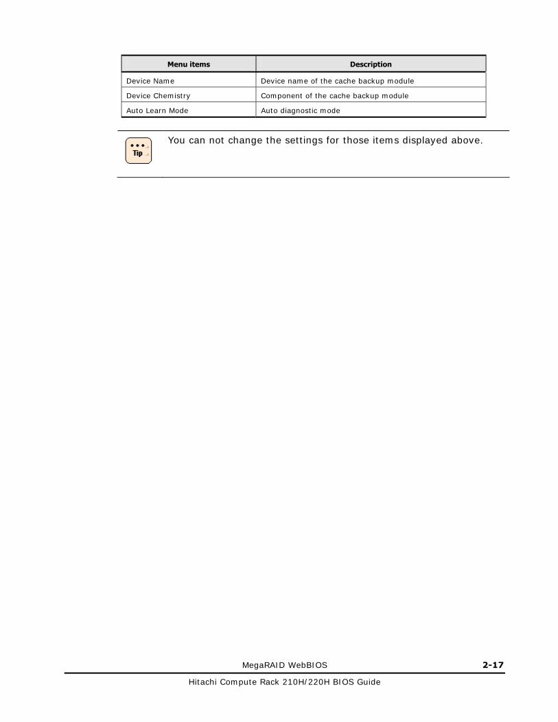
Hitachi Compute Rack 210H/220H BIOS Guide
Menu items Description
Device Name Device name of the cache backup module
Device Chemistry Component of the cache backup module
Auto Learn Mode Auto diagnostic mode
You can not change the settings for those items displayed above.

2-18 MegaRAID WebBIOS
Hitachi Compute Rack 210H/220H BIOS Guide
Controller properties submenu 2
Click Next in the Properties: Controller properties submenu 1 window. The following window is displayed.
The following table shows description of menu items in the window.
Table 2-9: Controller properties submenu 2 items
Menu items Description Setting/display value
Stop CC On Error Sets an operation when an error is detected at the consistency check
[No] / Yes
Maintain PD Fail History1 Sets whether or not a failed disk can be used
[Enabled (Registers failed disk information.)] / Disabled (Not register failed disk information.)
Controller BIOS1 Enables the RAID controller BIOS [Enabled] / Disabled
Link Speed2 Sets link speed of SAS interface When [Manage] is clicked, the window moves to Manage Link Speed submenu.
Unconfigured Good for Emergency1
Different type of drive using drive rebuilding
[Disabled] / Enabled
Schedule CC Sets a consistency check schedule
When [Supported] is clicked, the window moves to Schedule CC Page submenu.
StopOnError1 Sets whether or not boot the OS if a failure is detected at the system boot
[Disable] / Enabled
Disk Activity1 Sets switching disk LEDs [Disabled] / Enabled

MegaRAID WebBIOS 2-19
Hitachi Compute Rack 210H/220H BIOS Guide
Menu items Description Setting/display value
Global Hotspare for Emergency1
Different type of drive using Hotspare
[Disabled] / Enabled
Notes:
1 Use this item with the default setting.
2 This item is displayed when installed the RAID controller with cache backup module. Do not set this item because it is not supported.
Place the mouse cursor on a setting item and left-click the mouse to change the setting values. Or, left-click the mouse to move the cursor and enter a value from the keyboard. Click Submit after the setting.
2-20 MegaRAID WebBIOS
Hitachi Compute Rack 210H/220H BIOS Guide
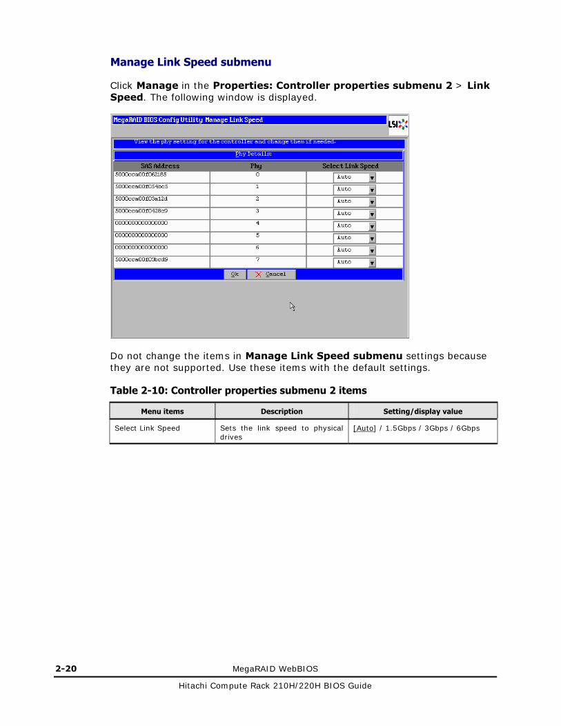
Manage Link Speed submenu
Click Manage in the Properties: Controller properties submenu 2 > Link Speed. The following window is displayed.
Do not change the items in Manage Link Speed submenu settings because they are not supported. Use these items with the default settings.
Table 2-10: Controller properties submenu 2 items
Menu items Description Setting/display value
Select Link Speed Sets the link speed to physical drives
[Auto] / 1.5Gbps / 3Gbps / 6Gbps

MegaRAID WebBIOS 2-21
Hitachi Compute Rack 210H/220H BIOS Guide
Schedule CC page submenu
Click Supported in the Properties: Controller properties submenu 2 > Schedule CC. The following window is displayed.
The following table shows description of menu items in the window.
Table 2-11: Schedule CC page menu items
Menu items Description Setting/display value
CC Frequency Sets the CC schedule function: Enable or Disable
[Disable] / Continuous / Hourly / Dairy / Weekly / Monthly
CC Start Time Sets on what time the consistency check starts
12:00 AM. to 11:00 PM. / [The nearest to the present time]
Select VDs to Exclude CC Specifies a disk array on which the consistency check is excluded
Choose any array configuration.
CC Start (mm/dd/yyyy) Sets on what date the consistency check starts
Choose any date.
CC Mode Sets if the consistency check is executed on multiple disk arrays
[Sequential] / Concurrent

2-22 MegaRAID WebBIOS
Hitachi Compute Rack 210H/220H BIOS Guide
Virtual drives: viewing and setting disk array information
You can display and change the information on the virtual drive (logical drive) that is already set. The virtual drive is a drive recognized by the OS as a logical entity on the disk array that is constructed of a group of physical drives. You can construct multiple virtual drives on the same disk array.
Click Virtual Drives in the main menu. The following window will be displayed.
Click a virtual drive for viewing information and changing the setting from the list on the upper right pane. Check Properties > Go. The Virtual Drive window will be displayed.

MegaRAID WebBIOS 2-23
Hitachi Compute Rack 210H/220H BIOS Guide
The following table shows description of menu items in the window.
NOTICE You need connect the AC cables of the system unit to a UPS, when you use the RAID controller without cache backup module and set Default Write to Always Write Back. Otherwise, the data corruption may result when blackout or momentary loss of power occurs.
If multiple virtual drives reside on the same Drive Group, keep the same setting for all the virtual drives.
Table 2-12: Virtual Drive menu items
Menu items Description Setting/display value
Properties
RAID Level RAID level -
Status Status of the virtual drive -
Strip Size Strip size of the virtual drive -
Capacity Size of the virtual drive -
Parity Size1 Parity size of the virtual drive
Policies
Access Access mode [RW (reading and writing)] / Read Only (reading only) / Blocked (access denied)
Read Read policy [Normal (no read ahead)] / Ahead (always read ahead)
Disk Cache Setting the cache installed in a physical disk
[Disable (cache: not used)] / [Enable (cache: used) / No Change (based on the disk setting)
I/O Setting the read-cache operation [Direct (cache: not used)] / Cached (cache: used)
Disable BGI Setting the background initialization
No (background initializing valid) / [Yes (background initializing invalid)]
Default Write2
Setting the write cache of the disk array
● RAID controller with cache backup module: Write Through / Always Write Back / [Write Back With BBU]
● RAID controller without cache backup module: [Write Through] / [Always Write Back] / Write Back With BBU
Notes:
1 This item is displayed when the virtual drive is RAID5 or 6.
2 If you use the RAID controller without cache backup module, use this item with the default setting when installing an OS. Even if the system unit is connected to a UPS, the install may not finish normally.

2-24 MegaRAID WebBIOS
Hitachi Compute Rack 210H/220H BIOS Guide
Drives: viewing physical disk information
You can display the information on the physical drive connected to the RAID controller.
Click Drives in the main menu. The following window is displayed.
Click a drive to review information from the list on the upper right pane. Check Properties > Go. The following window is displayed.

MegaRAID WebBIOS 2-25
Hitachi Compute Rack 210H/220H BIOS Guide
Click Next on the upper left pane, the following windows are displayed in order.

2-26 MegaRAID WebBIOS
Hitachi Compute Rack 210H/220H BIOS Guide
The following table shows description of menu items in the left side of those windows.
Table 2-13: Drives menu items
Menu items Description
Connector Connector of the connected disk array controller board
Enclosure ID ID number of the connected enclosure device
Mode name Disk mode name
Vendor Vendor name
Revision Firmware version
Slot Number Number of the slot installed
Device Type Device type
Connected Port Port number of the connected disk array controller board
Media Errors Number of detected media errors
Pred Fail Count Number of reported S.M.R.T warnings
SAS Address SAS address
Physical Drive State Status
Certified Certification
FDE Capable With or without encryption function
Max Device Speed Maximum speed at which a physical disk can operate
Link Speed Link speed of an interface
Temperature (Celsius) Disk temperature
Commisioned Hotspare Enabled/disabled protection by hotspare
Items in the table above can not be changed. Media Errors and Pred Fail Count are cleared when the system
unit is powered off.

MegaRAID WebBIOS 2-27
Hitachi Compute Rack 210H/220H BIOS Guide
Switching the display mode
This section describes switching disk array display modes in the main menu.
There are two types of display mode: Logical View and Physical View. The Logical View mode displays a list of disk array configurations that are already set. The Physical View mode displays a list of physical disks comprising a disk array configuration.
The Logical View mode is applied when the MegaRAID WebBIOS is started. To switch to the physical view mode, click Physical View in the Logical View mode of the main menu. To switch to the logical view mode, click Logical View in the Physical View mode of the main menu.
Logical View mode: ●Virtual drives (Logical drives) ● Drives (physical drives) ● Hot spares
Physical View mode: ● Drives (physical drives)

2-28 MegaRAID WebBIOS
Hitachi Compute Rack 210H/220H BIOS Guide
Building and editing virtual drives
This section describes the procedure for building virtual drives.
The building of disk arrays should be entirely performed with Configuration Wizard.
NOTICE Do not change the configuration of the virtual drives during system operations. If you change the configuration, all data will be lost from those physical drives due to change in the virtual drive.
Set each item to the recommended value unless otherwise specific directions are given. Otherwise, the system may not properly operate. We have no responsibility for the malfunction due to the setting except our recommended values.
The maximum number of the virtual drives you can construct per RAID controller is 64. The maximum number of the virtual drives you can construct on one Drive Group is 16.
Building virtual drive
This section describes the procedure for building new virtual drive. When you build a virtual drive, create a group of physical drives first and then configure the virtual drive (logical drive).
Building virtual drive for RAID 0, 1, 5, and 6
Here is a procedure for building virtual drive for RAID 0, 1, 5, and 6.

MegaRAID WebBIOS 2-29
Hitachi Compute Rack 210H/220H BIOS Guide
1. Click Configuration Wizard in the main menu.
2. The following window is displayed.
Click New Configuration or Add Configuration box, and then click Next.
NOTICE If you select New Configuration, all data in the disks is lost. Backup your required data before selecting New Configuration.
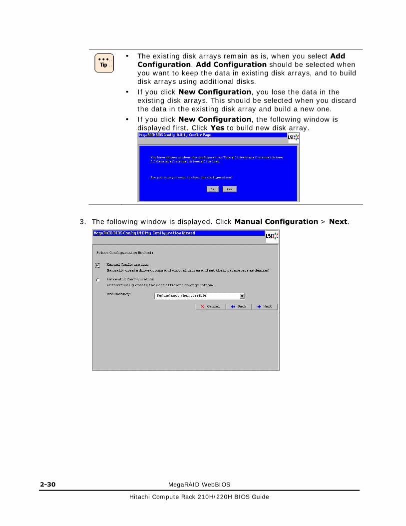
2-30 MegaRAID WebBIOS
Hitachi Compute Rack 210H/220H BIOS Guide
The existing disk arrays remain as is, when you select Add Configuration. Add Configuration should be selected when you want to keep the data in existing disk arrays, and to build disk arrays using additional disks.
If you click New Configuration, you lose the data in the existing disk arrays. This should be selected when you discard the data in the existing disk array and build a new one.
If you click New Configuration, the following window is displayed first. Click Yes to build new disk array.
3. The following window is displayed. Click Manual Configuration > Next.

MegaRAID WebBIOS 2-31
Hitachi Compute Rack 210H/220H BIOS Guide
4. The following window is displayed. Click physical drives in Drives pane for building virtual drive.
If you add a virtual drive to the already existing Drive Group, select nothing and go to the step 7.
The number of drives required varies depending on the RAID level to be set. The following table summarizes the number of drives required.
Table 2-14: Number of drives required
RAID level Number of drives required
RAID 0 (including JBOD) One or more
RAID 1 Two
RAID 5 Three or more
RAID 6 Four or more
RAID 6 with three physical drives and RAID 1 with three or more physical drives are not supported. If you configure those settings, the virtual drive may not operate properly.
You can select only a drive which status is "Unconfigured Good" (unused).
To select multiple drives, click the drives while pressing Ctrl key.

2-32 MegaRAID WebBIOS
Hitachi Compute Rack 210H/220H BIOS Guide
5. After selecting all physical drives to build a virtual drive, click Add To Array.
Status of those selected drives is Online that is displayed in the Drive Groups pane.
To release a physical drive from [Online], select the drive and click Reclaim.
6. Click Accept DG.
7. The following window is displayed. Click Next.
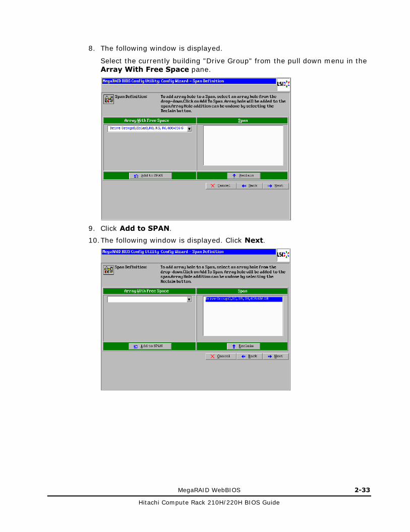
MegaRAID WebBIOS 2-33
Hitachi Compute Rack 210H/220H BIOS Guide
8. The following window is displayed.
Select the currently building "Drive Group" from the pull down menu in the Array With Free Space pane.
9. Click Add to SPAN.
10. The following window is displayed. Click Next.

2-34 MegaRAID WebBIOS
Hitachi Compute Rack 210H/220H BIOS Guide
11. The following window is displayed. Specify the RAID level, strip size, read policy, write policy, and virtual drive size as shown in the table below:
Set each item in the following value to the recommended value, unless otherwise specified.
NOTICE You need connect the AC cables of the system unit to a UPS, when you use the RAID controller without cache backup module and set Write Policy to Always Write Back. Otherwise, the data corruption may result when blackout or momentary loss of power occurs.

MegaRAID WebBIOS 2-35
Hitachi Compute Rack 210H/220H BIOS Guide
Table 2-15: Specify the RAID level, strip size, and policies
Menu items Description Setting/display value
RAID Level1 RAID Level Specify any level.
Strip Size Strip size 8KB / 16KB / 32KB / [64KB] / 128KB / 256KB / 512KB / 1MB
Access Policy Access policy [RW (reading and writing)] /
Read Only (reading only) /
Blocked (access denied)
Read Policy Read policy [Normal (no read ahead)] / Ahead (always read ahead)
Write Policy2 Write policy ● RAID controller with cache backup module: Write Through / Always Write Back / [Write Back With BBU]
● RAID controller without cache backup module:[Write Through] / [Always Write Back] / Write Back With BBU
IO Policy Read-cache operation
[Direct (cache: not used)] / Cached (cache: used)
Disk Cache3 Setting the disk cache
[Disable (cache: not used)] / Enable (cache: used) / No change (depending on the disk setting)
Disable BGI3 Setting the background initialization
No (background initializing valid) /
[Yes (background initializing invalid)]
Select Size4 Size of a disk array Entering the maximum capacity value. (minimum allowable value: 64 KB)
Notes:
1 If you add a virtual drive to the already existing Drive Group, you can not change the RAID level.
2 If you use the RAID controller without cache backup module, use this item with the default setting when installing an OS. Even if the system unit is connected to a UPS, the install may not finish normally.
3 Change from the default value to the recommended value.
4 When you configure "Select Size", check the maximum allowable capacity displayed under [Next LD, Possible RAID Levels] at the right of the window. And then you specify the value at your discretion within the maximum capacity in accordance with the specified RAID level. When you enter the value, completely delete the value in the box first and then enter the value. When you enter the maximum capacity, enter all the digits precisely including decimal places and make sure you do not skip even zeros.

2-36 MegaRAID WebBIOS
Hitachi Compute Rack 210H/220H BIOS Guide
If multiple virtual drives reside on the same Drive Group, keep the same setting for all the virtual drives.
If you specify a larger disk array size than the maximum capacity, Unacceptable size is displayed on the window and all the setting items are initialized. You need to reset all items to the correct size.
12. Click Accept.
13. The following window is displayed. Click Yes.
– When you specify Write Through to Write Policy
– When you specify Always Write Back to Write Policy
– When you specify Write Back With BBU to Write Policy

MegaRAID WebBIOS 2-37
Hitachi Compute Rack 210H/220H BIOS Guide
14. The following window is displayed. Click Next.
The following window is displayed before above window is displayed When you specify Write Back With BBU to Write Policy. Click Yes.

2-38 MegaRAID WebBIOS
Hitachi Compute Rack 210H/220H BIOS Guide
15. The following window is displayed. Confirm the settings, and then click Accept.
If the settings are wrong, click Back and return to the step 11.
16. The following window is displayed. Click Yes.
17. The following window is displayed. Click No.
The window returns to the main menu.
18. Initialize the created virtual drive.
See Initializing virtual drive on page 2-49.

MegaRAID WebBIOS 2-39
Hitachi Compute Rack 210H/220H BIOS Guide
Building virtual drive for RAID 10
Here is a procedure for building virtual drive for RAID 10. The following table shows the number of required physical drives.
Table 2-16: Number of disks required
RAID level Number of drives required
RAID 10 Four, six, or eight
1. Click Configuration Wizard in the main menu.
2. The following window is displayed.
Click New Configuration or Add Configuration box, and then click Next.

2-40 MegaRAID WebBIOS
Hitachi Compute Rack 210H/220H BIOS Guide
NOTICE If you select New Configuration, all data in the disks is lost.
Backup your required data before selecting New Configuration.
The existing disk arrays remain as is, when you select Add Configuration. Add Configuration should be selected when you want to keep the data in existing disk arrays, and to build disk arrays using additional disks.
If you click New Configuration, you lose the data in the existing disk arrays. This should be selected when you discard the data in the existing disk array and build a new one.
If you click New Configuration, the following window is displayed first. Click Yes to build new disk array.
3. The following window is displayed. Click Manual Configuration > Next.

MegaRAID WebBIOS 2-41
Hitachi Compute Rack 210H/220H BIOS Guide
4. The following window is displayed. Click a physical drive in Drives pane for building virtual drive.
If you build a new virtual drive, select two physical drives.
If you add a virtual drive to the already existing Drive Group, select nothing and go to the step 7.
You can select only a drive which status is "Unconfigured Good" (unused).
To select multiple drives, click the drives while pressing Ctrl key.

2-42 MegaRAID WebBIOS
Hitachi Compute Rack 210H/220H BIOS Guide
5. After selecting two physical drives to build a virtual drive, click Add To Array.
Status of those selected disks is Online that is displayed in the Drive Groups pane.
To release a physical drive from [Online], select the drive and click Reclaim.
6. Click Accept DG.
7. The following window is displayed. If you build a new virtual drive, repeat the steps 4, 5, and 6 until you select all the physical drives used for RAID 10. And then, click Next. If you add a virtual drive to the already existing Drive Group, click Next.

MegaRAID WebBIOS 2-43
Hitachi Compute Rack 210H/220H BIOS Guide
8. The following window is displayed. If you build a new virtual drive, select all the Drive Group added in the step 7 from the pull down menu in the Array With Free Space pane. If you add a virtual drive to the already existing Drive Group, select that from the pull down menu in the Array With Free Space pane.
9. Click Add to SPAN.
If you add a virtual drive to the already existing Drive Group, select either one of the Drive Group and then click Add to SPAN. Then all the currently building Drive Groups are selected.
10. The following window is displayed. Click Next.
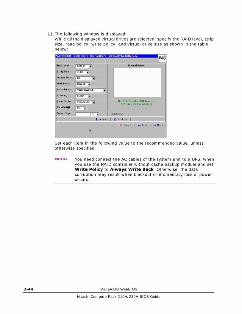
2-44 MegaRAID WebBIOS
Hitachi Compute Rack 210H/220H BIOS Guide
11. The following window is displayed.
While all the displayed virtual drives are selected, specify the RAID level, strip size, read policy, write policy, and virtual drive size as shown in the table below:
Set each item in the following value to the recommended value, unless otherwise specified.
NOTICE You need connect the AC cables of the system unit to a UPS, when you use the RAID controller without cache backup module and set Write Policy to Always Write Back. Otherwise, the data corruption may result when blackout or momentary loss of power occurs.

MegaRAID WebBIOS 2-45
Hitachi Compute Rack 210H/220H BIOS Guide
Table 2-17: Specify the RAID level, strip size, and policies
Menu items Description Setting/display value
RAID Level RAID Level [RAID 10]
Strip Size Strip size 8KB / 16KB / 32KB / [64KB] / 128KB / 256KB / 512KB / 1MB
Access Policy Access policy [RW (reading and writing)] /
Read Only (reading only) /
Blocked (access denied)
Read Policy Read policy [Normal (no read ahead)] / Ahead (always read ahead)
Write Policy1 Write policy ● RAID controller with cache backup module: Write Through / Always Write Back / [Write Back With BBU]
● RAID controller without cache backup module:[Write Through] / [Always Write Back] / Write Back With BBU
IO Policy Read-cache operation
[Direct (cache: not used)] / Cached (cache: used)
Disk Cache2 Setting the disk cache
[Disable (cache: not used)] / Enable (cache: used) / No change (depending on the disk setting)
Disable BGI2 Setting the background initialization
No (background initializing valid) /
[Yes (background initializing invalid)]
Select Size3 Size of a disk array Entering the maximum capacity value. (minimum allowable value: 64 KB)
Notes:
1 If you use the RAID controller without cache backup module, use this item with the default setting when installing an OS. Even if the system unit is connected to a UPS, the install may not finish normally.
2 Change from the default value to the recommended value.
3 When you configure "Select Size", check the maximum allowable capacity displayed under [Next LD, Possible RAID Levels] at the right of the window. And then you specify the value at your discretion within the maximum capacity in accordance with the specified RAID level. When you enter the value, completely delete the value in the box first and then enter the value. When you enter the maximum capacity, enter all the digits precisely including decimal places and make sure you do not skip even zeros.
If multiple virtual drives reside on the same Drive Group, keep the same setting for all the virtual drives.
If you specify a larger disk array size than the maximum capacity, Unacceptable size is displayed on the window and all the setting items are initialized. You need to reset all items to the correct size.
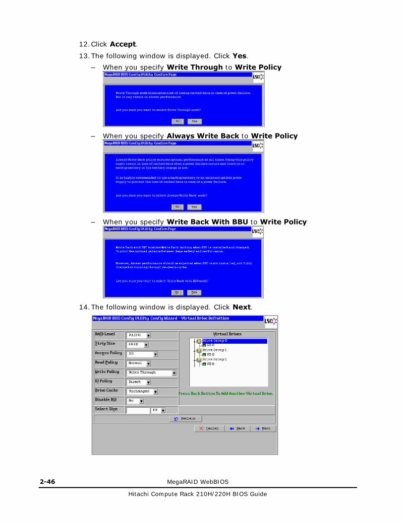
2-46 MegaRAID WebBIOS
Hitachi Compute Rack 210H/220H BIOS Guide
12. Click Accept.
13. The following window is displayed. Click Yes.
– When you specify Write Through to Write Policy
– When you specify Always Write Back to Write Policy
– When you specify Write Back With BBU to Write Policy
14. The following window is displayed. Click Next.

MegaRAID WebBIOS 2-47
Hitachi Compute Rack 210H/220H BIOS Guide
The following window is displayed before above window is displayed when you specify Write Back With BBU to Write Policy. Click Yes.
15. The following window is displayed. Confirm the settings, and then click Accept.
If the settings are wrong, click Back and return to the step 11.
16. The following window is displayed. Click Yes.

2-48 MegaRAID WebBIOS
Hitachi Compute Rack 210H/220H BIOS Guide
17. The following window is displayed. Click No.
The window returns to the main menu.
18. Initialize the created virtual drive.
See Initializing virtual drive on page 2-49.
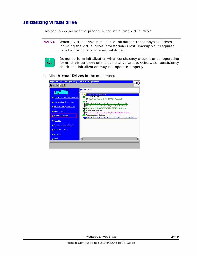
MegaRAID WebBIOS 2-49
Hitachi Compute Rack 210H/220H BIOS Guide
Initializing virtual drive
This section describes the procedure for initializing virtual drive.
NOTICE When a virtual drive is initialized, all data in those physical drives including the virtual drive information is lost. Backup your required data before initializing a virtual drive.
Do not perform initialization when consistency check is under operating for other virtual drive on the same Drive Group. Otherwise, consistency check and initialization may not operate properly.
1. Click Virtual Drives in the main menu.

2-50 MegaRAID WebBIOS
Hitachi Compute Rack 210H/220H BIOS Guide
2. The following window is displayed. In the list of virtual drives displayed in the upper right pane, click a virtual drive configuration to be initialized.
3. Click Slow Initialize > Go.
4. The following window is displayed. Click Yes.
5. The following progress of initialization in the left pane is displayed.

MegaRAID WebBIOS 2-51
Hitachi Compute Rack 210H/220H BIOS Guide
6. Wait until the processing is completed to 100%.
A guideline of initialization time is shown in the following table.
Table 2-18: Guideline of initialization
Single drive capacity Initialization time
146 GB (SAS / 2.5 inch type HDD) Approximately 16 minutes
300 GB (SAS / 2.5 inch type HDD) Approximately 40 minutes
450 GB (SAS / 2.5 inch type HDD) Approximately 60 minutes
600 GB (SAS / 2.5 inch type HDD) Approximately 80 minutes
900 GB (SAS / 2.5 inch type HDD) Approximately 120 minutes
1.2 TB (SATA2 / 2.5 inch type HDD) Approximately 160 minutes
500 GB (SATA2 / 2.5 inch type HDD) Approximately 670 minutes
1 TB (SATA2 / 2.5 inch type HDD) Approximately 1340 minutes
100 GB (SATA2 / 2.5 inch type SSD) Approximately 10 minutes
200 GB (SATA2 / 2.5 inch type SSD) Approximately 20 minutes
The initialization time varies depending on the physical drive capacity regardless of the RAID level or virtual drive capacity.
7. When initialization is completed to 100%, click Home to return to the main menu.

2-52 MegaRAID WebBIOS
Hitachi Compute Rack 210H/220H BIOS Guide
Deleting disk arrays
This section describes the procedure for deleting virtual drive.
NOTICE When a virtual drive is deleted, all data in those physical drives including the virtual drive information is lost. Backup your required data before deleting a virtual drive.
Deleting all virtual drives simultaneously 1. Click Configuration Wizard in the main menu.
2. The following window is displayed. Click Clear Configuration > Next.

MegaRAID WebBIOS 2-53
Hitachi Compute Rack 210H/220H BIOS Guide
3. The following window is displayed. Click Yes.

2-54 MegaRAID WebBIOS
Hitachi Compute Rack 210H/220H BIOS Guide
Deleting virtual drive selectively
When you delete a virtual drive on the Drive Group, deleting the last build virtual drive is supported only. If you want to delete an older virtual drive, delete virtual drives in the reverse order starting at the last build virtual drive and ending at the virtual drive you want to delete.
1. Click Virtual Drives in the main menu.
2. The following window is displayed.
From the list displayed in the upper right pane, click a virtual drive to be deleted. Then click Properties > Go.

MegaRAID WebBIOS 2-55
Hitachi Compute Rack 210H/220H BIOS Guide
3. The following window is displayed. Click Delete > Go in the Operations pane.
4. The following window is displayed. Click Yes.

2-56 MegaRAID WebBIOS
Hitachi Compute Rack 210H/220H BIOS Guide
Checking disk arrays for consistency
This section describes how to check the consistency of disk arrays.
Consistency check can be done from MegaRAID Storage Manager. See MegaRAID Storage Manage Instruction Manual, contained in the "DriverKit & Manual" CD-ROM for how to check the consistency from the MegaRAID Storage Manager.
Do not perform consistency check when initialization is under operating for other virtual drive on the same Drive Group. Otherwise, initialization and consistency check may not operate properly.
You can perform consistency check only for RAID 1, 5, 6, and 10.
1. Click Virtual Drives in the main menu.

MegaRAID WebBIOS 2-57
Hitachi Compute Rack 210H/220H BIOS Guide
2. The following window is displayed. From the list displayed in the upper right pane, click a virtual drive to be checked the consistency, and then check Properties > Go.
3. The following window is displayed. Click CC > Go.

2-58 MegaRAID WebBIOS
Hitachi Compute Rack 210H/220H BIOS Guide
4. The progress of consistency check is displayed in the following Operations pane.
5. Wait until the processing is completed to 100%.
6. When the consistency check is completed to 100%, click Home to return to the main menu.

MegaRAID WebBIOS 2-59
Hitachi Compute Rack 210H/220H BIOS Guide
Changing the order of booting virtual drives
Do not change the settings of this menu items. This function is not supported by Hitachi Compute Rack System. Use defaults setting for all the items.

2-60 MegaRAID WebBIOS
Hitachi Compute Rack 210H/220H BIOS Guide
Making hot spares
This section describes a procedure of making a hot spare (reserve drive).
Two types of hot spare are available: "global hot spares" can be used for all virtual drives and "dedicated hot spares (local spares)" are dedicated to the specific virtual drive. Choose the type as required.
Before you make a hot spares, you need to build a virtual drive with redundancy (RAID 1, 5, 6, 10).
For the disk array configured with HDDs, install HDD as reserve drive; for the disk array configured with SSDs, install SSD as reserve drive. Other type of disk array cannot be configured as reserve drive.
1. Click the physical drive you want to use as a hot spare from the list in the Logical View / Physical View in the main menu.
You can select only a drive which status is "Unconfigured Good" (unused).

MegaRAID WebBIOS 2-61
Hitachi Compute Rack 210H/220H BIOS Guide
2. The following window is displayed. If you set the drive as "global hot spare", check Make Global HSP. If you set the drive as "dedicated hot spare", click the logical drive to be protected in the upper right pane, and then check Dedicated HSP.
3. Check Make Global HSP or Make Dedicated HSP, and then click Go.
The drive is set as hot spare.

2-62 MegaRAID WebBIOS
Hitachi Compute Rack 210H/220H BIOS Guide
Removing hot spares
This section describes a procedure of remove a hot spare.
1. Click the physical drive used as a hot spare from the list in the Logical View / Physical View in the main menu.
2. The following window is displayed.
Check Remove HOTSPARE, and then click Go.
The hot spare is removed.

MegaRAID WebBIOS 2-63
Hitachi Compute Rack 210H/220H BIOS Guide
Rebuilding virtual drives
This section describes a procedure of rebuilding virtual drive in case of trouble that has occurred on a physical disk in the redundant disk array configuration.
Usually, rebuilding will work automatically after you replace the failed disk in hot-plug. Also, if you set up hot spares, rebuilding will work automatically.
The following is a procedure of manual rebuilding in case that rebuilding doesn’t work automatically by some reason.
1. Click Drives in the main menu.
2. The following window is displayed.
Click a disk status is Offline, and then click Rebuild > Go.

2-64 MegaRAID WebBIOS
Hitachi Compute Rack 210H/220H BIOS Guide
3. The progress of rebuilding is displayed in the left pane of the following window.
4. Wait until the processing is completed to 100%.
A guideline of rebuilding time is shown in the following table.
Table 2-19: Guideline of rebuilding time
RAID level Capacity of a virtual drive Rebuilding time
146 GB (SAS 146 GB / 2.5 inch type HDD × 2) Approximately 16 minutes
500 GB (SATA2 500 GB / 2.5 inch type HDD × 2) Approximately 60 minutes
RAID 1
100 GB (SATA2 100 GB / 2.5 inch type SSD × 2) Approximately 10 minutes
292 GB (SAS 146 GB / 2.5 inch type HDD × 3) Approximately 16 minutes
1 TB (SATA2 500 GB / 2.5 inch type HDD × 3) Approximately 60 minutes
RAID 5
200 GB (SATA2 100 GB / 2.5 inch type SSD × 3) Approximately 10 minutes
292 GB (SAS 146 GB / 2.5 inch type HDD × 4) Approximately 16 minutes
1 TB (SATA2 500 GB / 2.5 inch type HDD × 4) Approximately 60 minutes
RAID 6
200 GB (SATA2 100 GB / 2.5 inch type SSD × 4) Approximately 10 minutes
292 GB (SAS 146 GB / 2.5 inch type HDD × 4) Approximately 16 minutes
1 TB (SATA2 500 GB / 2.5 inch type HDD × 4) Approximately 50 minutes
RAID 10
200 GB (SATA2 100 GB / 2.5 inch type SSD × 4) Approximately 10 minutes
The rebuild time is proportional to the capacity of the physical drives.
5. When rebuilding is completed to 100%, click Home to return to the main menu.

MegaRAID WebBIOS 2-65
Hitachi Compute Rack 210H/220H BIOS Guide
Adding capacity to virtual drives
This section describes a procedure of adding capacity to a virtual drive in the disk array such as RAID level 0, 5, and 6 configurations.
Adding capacity can be done from MegaRAID Storage Manager. See MegaRAID Storage Manage Instruction Manual, contained in the "DriverKit & Manual" CD-ROM.
You cannot cancel adding capacity to a virtual drive in the middle. If multiple virtual drives reside on the same Drive Group or if all the
capacity of the Drive Group has not been used up, capacity expansion is not supported.
In order to add capacity, you need to have physical drives with "Unconfigured Good" status.
1. Click Virtual Drives in the main menu.

2-66 MegaRAID WebBIOS
Hitachi Compute Rack 210H/220H BIOS Guide
2. The following window is displayed. From the list displayed in the upper right pane, click a virtual drive to add capacity, and then check Properties > Go.
3. The following window is displayed. Click Adv Opers > Go.

MegaRAID WebBIOS 2-67
Hitachi Compute Rack 210H/220H BIOS Guide
4. The following window is displayed. Check Change RAID Level and Add Drive, select the physical drives used for adding capacity from the list below, and then click Go.
To select multiple drives, click the drives while pressing Ctrl key.
5. The following window is displayed. Click Yes.

2-68 MegaRAID WebBIOS
Hitachi Compute Rack 210H/220H BIOS Guide
6. The following window is displayed. Click VD Progress Info.
7. The progress of adding capacity is displayed in the left pane of the following
window.

MegaRAID WebBIOS 2-69
Hitachi Compute Rack 210H/220H BIOS Guide
8. Wait until the processing is completed to 100%.
A guideline of adding capacity time is shown in the following table.
Table 2-20: Guideline of adding capacity time
RAID level Adding capacity to a virtual drive Adding time
438 GB (SAS 146 GB / 2.5 inch type HDD × 3) Approximately 100 minutes
1.5 TB (SATA2 500 GB / 2.5 inch type HDD × 3) Approximately 610 minutes
RAID 0
300 GB (SATA2 100 GB / 2.5 inch type SSD × 3) Approximately 60 minutes
292 GB (SAS 146 GB / 2.5 inch type HDD × 3) Approximately 80 minutes
1 TB (SATA2 500 GB / 2.5 inch type HDD × 3) Approximately 480 minutes
RAID 5
200 GB (SATA2 100 GB / 2.5 inch type SSD × 3) Approximately 45 minutes
292 GB (SAS 146 GB / 2.5 inch type HDD × 4) Approximately 80 minutes
1 TB (SATA2 500 GB / 2.5 inch type HDD × 4) Approximately 580 minutes
RAID 6
200 GB (SATA2 100 GB / 2.5 inch type SSD × 4) Approximately 45 minutes
The adding capacity time is proportional to the capacity of the virtual drives.
9. When adding capacity is completed to 100%, click Home to return to the main menu.

2-70 MegaRAID WebBIOS
Hitachi Compute Rack 210H/220H BIOS Guide
Changing the write policy
This section describes a procedure of changing the write policy of a virtual drive. You can expect better write performance if you enable the write cache of the virtual drive.
NOTICE
You need connect the AC cables of the system unit to a UPS, when you use the RAID controller without cache backup module and set Write Policy to Always Write Back. Otherwise, the data corruption may result when blackout or momentary loss of power occurs.
If you use the RAID controller without cache backup module, use Write Through setting when installing an OS. Even if the system unit is connected to a UPS, the install may not finish normally.
If you use the RAID controller with cache backup module, use only Write Back With BBU setting. Otherwise, write performance may be compromised.
If multiple virtual drives reside on the same Drive Group, keep the same setting for all the virtual drives.
1. Click Virtual Drives in the main menu.

MegaRAID WebBIOS 2-71
Hitachi Compute Rack 210H/220H BIOS Guide
2. The following window is displayed. From the list displayed in the upper right pane, click a virtual drive to change write policy, and then check Properties > Go.
3. The following window is displayed.
Select the write policy from Default Write displayed in the Policies pane.
The setting is shown in the following table.
Table 2-20: Default Write settings
Setting Description
Always Write Back Write cache is enabled.
Write Through Write cache is disabled.
Write Back With BBU Write cache is enabled only when a cache backup module is connected to the RAID controller.

2-72 MegaRAID WebBIOS
Hitachi Compute Rack 210H/220H BIOS Guide
4. Click Change.
5. The following window is displayed. Click Yes.
– When you specify Write Through to Default Write
– When you specify Always Write Back to Default Write
– When you specify Write Back With BBU to Default Write
The following window is displayed after above window is displayed when you specify Write Back With BBU to Default Write. Click Yes.

MegaRAID WebBIOS 2-73
Hitachi Compute Rack 210H/220H BIOS Guide
6. Click Home to return to the main menu.
You need to configure the write policy for each of the virtual drives.If one or more virtual drives are build, configure the write policy for all of the virtual drives.

2-74 MegaRAID WebBIOS
Hitachi Compute Rack 210H/220H BIOS Guide
Disk with foreign configuration
This section describes how to deal with a disk with a different configuration detected by the RAID controller configuration.
Difference in configuration between disks may be caused by the following conditions.
Table2-22: Conditions to generate foreign configuration
Conditions to generate foreign configuration
A disk failed and could not be recognized. Then the disk has been restored to be recognized.
1. If the following window is displayed when starting the MegaRAID WebBIOS, click Preview.

MegaRAID WebBIOS 2-75
Hitachi Compute Rack 210H/220H BIOS Guide
2. If the displayed configuration is correct, click Import. If the displayed configuration is incorrect, click Cancel to return the windows on the step 1, and then click Clear.
When you click Clear, Previous foreign configuration will be lost. Do you want to proceed? is displayed. Then click Yes. The previous foreign configuration is eliminated.

2-76 MegaRAID WebBIOS
Hitachi Compute Rack 210H/220H BIOS Guide
Exiting MegaRAID WebBIOS 1. Return to the main menu.
2. From the main menu, click Exit.
The Exit Confirmation window is displayed.
3. Click Yes.
Clicking No returns window to the main menu.
4. In response to the following message, powers off the system unit or restart the system unit by pressing Ctrl + Alt + Delete keys.

MegaRAID WebBIOS 2-77
Hitachi Compute Rack 210H/220H BIOS Guide
Status
This section describes statuses of virtual drives / physical drives displayed in MegaRAID WebBIOS.
Status of the virtual drive
Here is a list of statuses for disk arrays.
Table 2-23: Statuses for disk arrays
Status Description
Optimal Normal. The virtual drive is operable.
Partially Degraded One physical drive fails in a RAID 6 virtual drive.
Degraded One physical drive fails in a RAID 1, 5, or 10 virtual drive.
Offline The virtual drive is inoperable because of either failures in multiple drive s in a redundant disk array or a failure in a drive in a non-redundant disk array.
Status of the physical drive
Table 2-24: Status of the disk
Status Description
Online Normal.
Offline/Failed A fault has occurred.
The physical drive is separated from the disk array due to a failure.
Rebuild Rebuilding is underway.
Global Hot Spare The physical drive is set as a global hot spare.
Dedicated Hot Spare The physical drive is set as a dedicated hot spare.
Unconfigured Good This is not used for a disk array.
Unconfigured Bad A fault has occurred.
The unrecognizable disk is restored to recognizable.
Missing A fault has occurred.
A "normal" disk has been removed.

2-78 MegaRAID WebBIOS
Hitachi Compute Rack 210H/220H BIOS Guide

Hitachi Compute Rack 210H/220H BIOS Guide

MK-90CRH008-02
Hitachi Data Systems
Corporate Headquarters 2845 Lafayette Street Santa Clara, California 95050-2639 U.S.A. www.hds.com
Regional Contact Information
Americas +1 408 970 1000 [email protected]
Europe, Middle East, and Africa +44 (0) 1753 618000 [email protected]
Asia Pacific +852 3189 7900 [email protected]


![BIOS SECTION P7230 - Fujitsu · BIOS SECTION P7230. 2 LifeBook P7000 Notebook BIOS ... Press [F2] once the Fujitsu logo appears on the screen. This will open the main menu of the](https://img.dokumen.tips/doc/110x75/5b5c46157f8b9a65028b805c/bios-section-p7230-bios-section-p7230-2-lifebook-p7000-notebook-bios-.jpg)


![Main Menu Main Menu [dummy slide]. Main Menu Servant-Leaders or Leaders of Servants? A.D. 376 - 664](https://img.dokumen.tips/doc/110x75/56649efa5503460f94c0b7fe/main-menu-main-menu-dummy-slide-main-menu-servant-leaders-or-leaders-of.jpg)