Embed Size (px)
Citation preview
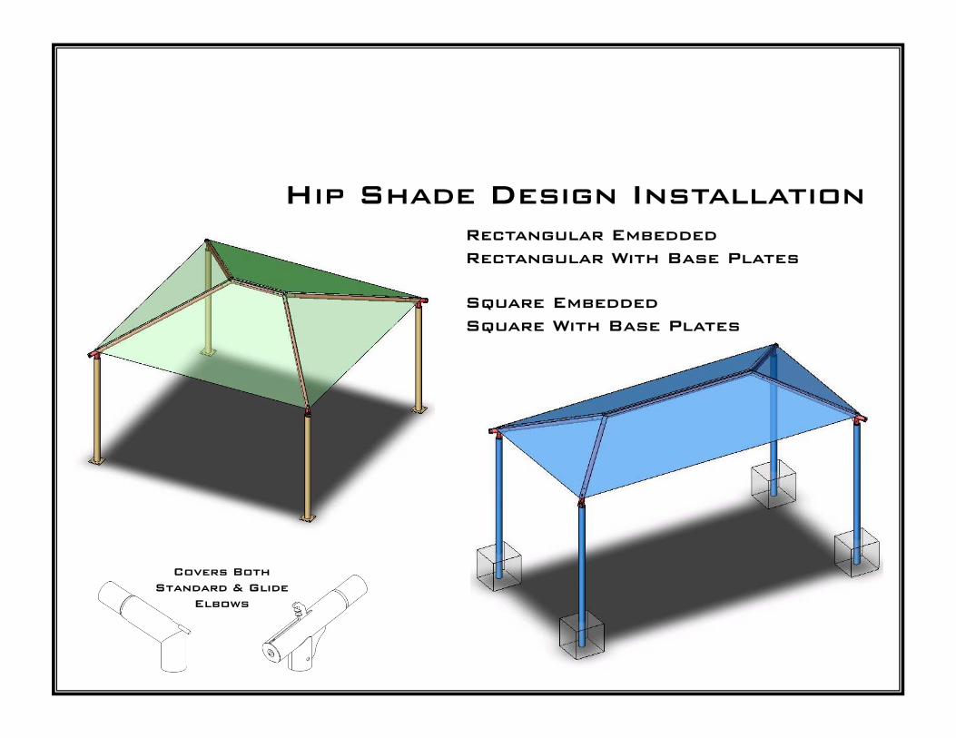
Hip Shade Design InstallationRectangular EmbeddedRectangular With Base Plates
Square EmbeddedSquare With Base Plates
Covers BothStandard & Glide
Elbows
INSTALLATION INTRODUCTION
It is very important that you read this entire manual before beginning the installation process.We are continuously striving to improve our product, and the Installation Introduction willContain the latest up-to-date information.
STORAGE:When Shade Unit equipment is received at the job site it should be installed as soon as possible (within a few days). Wepackage the equipment components to keep them safe and damage-free during shipment. However, the packaging materialis not suited for periods of extended storage in an uncontrolled environments. The combination of moisture in the air mixedwith heat generated inside the plastic shrink-wrap may cause damage to the finish of powdercoated frame members.
If an immediate installation is not possible, certain steps should be taken to minimize the risk of damage to the components.If Shade components must be stored, ideally they should be kept in a controlled warehouse or storage container environmentaway from heat and moisture. If this is not possible, the packaging material should be removed. Care is recommended whenusing cutting blades to remove packaging Keep blades away from powdercoated surfaces to avoid damage to finishusing cutting blades to remove packaging. Keep blades away from powdercoated surfaces to avoid damage to finish..
INVENTORY:It is very important that you inventory all Shade equipment received using the Packing List that shipped with your unit.Review all items for proper quantities and check for any damaged components.
Please report any items discovered missing within 72-Hours from time of delivery.
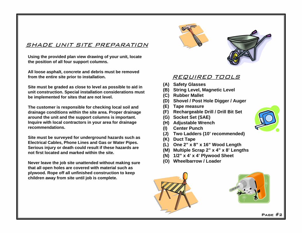
SHADE UNIT SITE PREPARATION
Using the provided plan view drawing of your unit, locatethe position of all four support columns.
All loose asphalt, concrete and debris must be removedfrom the entire site prior to installation.
Site must be graded as close to level as possible to aid inunit construction. Special installation considerations mustbe implemented for sites that are not level.
The customer is responsible for checking local soil anddrainage conditions within the site area. Proper drainagearound the unit and the support columns is important.Inquire with local contractors in your area for drainagerecommendations.
Site must be surveyed for underground hazards such asElectrical Cables, Phone Lines and Gas or Water Pipes.Serious injury or death could result if these hazards arenot first located and marked within the site.
Never leave the job site unattended without making surethat all open holes are covered with material such as plywood. Rope off all unfinished construction to keepchildren away from site until job is complete.
REQUIRED TOOLS(A) Safety Glasses(B) String Level, Magnetic Level(C) Rubber Mallet(D) Shovel / Post Hole Digger / Auger(E) Tape measure(F) Rechargeable Drill / Drill Bit Set(G) Socket Set (SAE)(H) Adjustable Wrench(I) Center Punch(J) Two Ladders (10’ recommended)(K) Duct Tape(L) One 2” x 8” x 16” Wood Length(M) Multiple Scrap 2” x 4” x 8’ Lengths(N) 1/2” x 4’ x 4’ Plywood Sheet(O) Wheelbarrow / Loader
Page #2
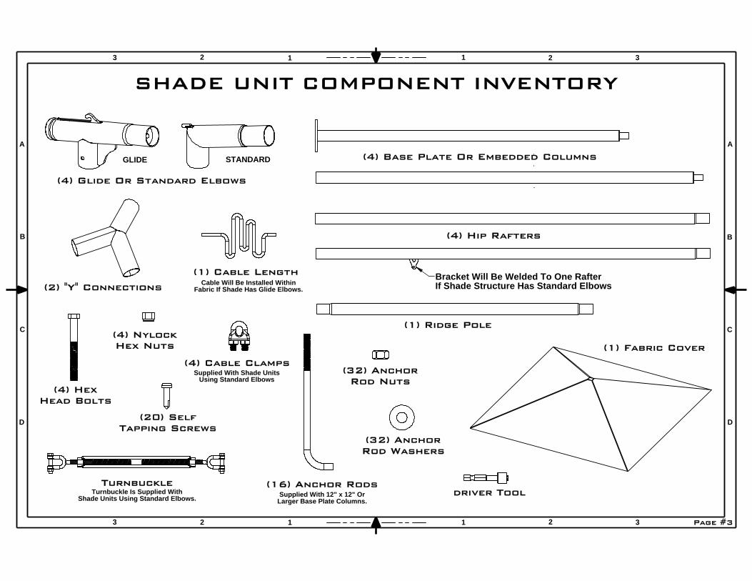
(4) Base Plate Or Embedded Columns
(4) Hip Rafters
(2) "Y" Connections
(4) Glide Or Standard Elbows
STANDARD
(1) Fabric Cover
Page #3
TurnbuckleTurnbuckle Is Supplied With
Shade Units Using Standard Elbows. Supplied With 12" x 12" OrLarger Base Plate Columns.
(1) Cable LengthCable Will Be Installed Within
Fabric If Shade Has Glide Elbows.
(4) NylockHex Nuts
(4) HexHead Bolts
Supplied With Shade UnitsUsing Standard Elbows
(32) AnchorRod Nuts
(16) Anchor Rods
(32) AnchorRod Washers
driver Tool
(20) SelfTapping Screws
2 1 32
A
B
C
D
A
B
C
D
3 2 1 1 2 3
3 1
GLIDE
SHADE UNIT COMPONENT INVENTORY
(4) Cable Clamps
Bracket Will Be Welded To One RafterIf Shade Structure Has Standard Elbows
(1) Ridge Pole
6"
1"
TYP.
SQUARE11"
7 1/2"
3 3/4"
1 1/4" 20" SQUARE
2 5/8"
TYP.7 3/8"
1 1/8"
SQUARE
TYP10"
16"
5"1" TYP.
SQUARE10"
7"
3 1/2"
Concrete Washer & NutGrout
Under PlateWasher & Nut
BasePlate
Concrete Anchor
Con
cret
e
ReinforcementSteel Rod
3"TYP.
SQUARE WIDTH
DEPTH
3" TYP.
1"
TYP.
SQUARE12"
8"
4"
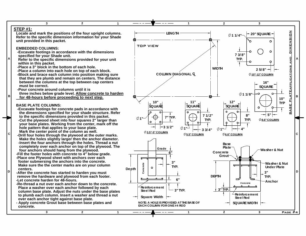
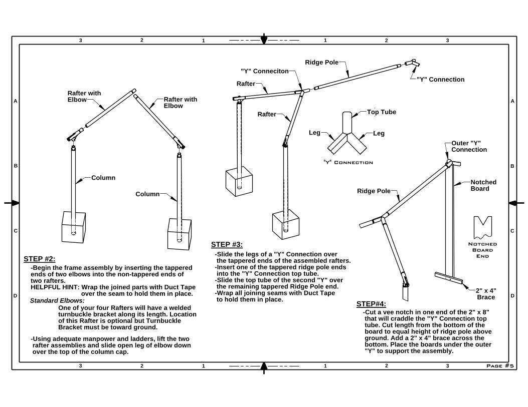
STEP #1:
concrete.
Locate and mark the positions of the four upright columns.Refer to the specific dimension information for your Shadeunit provided in this packet.
EMBEDDED COLUMNS: -Excavate footings in accordance with the dimensions specified for your Shade unit. Refer to the specific dimensions provided for your unit within in this packet. -Place a 3" block in the bottom of each hole. -Place a column into each hole on top of each block. -Block and brace each column into position making sure that they are plumb and remain on centers. The distance between the columns at the top between cap centers must be correct. -Pour concrete around columns until it is three inches below grade level. Allow concrete to harden for 48-hours before proceeding to next step.
BASE PLATE COLUMNS: -Excavate footings for concrete pads in accordance with the dimensions specified for your shade structure. Refer to the specific dimensions provided in this packet. -Cut the plywood sheet into four squares 2" larger than your base plates. Working from the center, mark off the hole pattern that applies to your base plate. Mark the center point of the column as well. -Drill four holes through the plywood at the outer marks. Make the holes slightly larger then the anchor diameter. -Insert the four anchors through the holes. Thread a nut completely over each anchor on top of the plywood. The four anchors should hang from the plywood.-Fill the footer holes with concrete to 4" below grade.-Place one Plywood sheet with anchors over each footer submersing the anchors into the concrete. Make sure the the center marks are on your column centers.-After the concrete has started to harden you must remove the hardware and plywood from each footer.-Let concrete harden for 48-hours.-Re-thread a nut over each anchor down to the concrete. Place a washer over each anchor followed by each column base plate. Adjust the nuts under the base plates to plumb each column. Insert a washer and thread a nut over each anchor tight against base plate.- Apply concrete Grout base between base plates and
Page #41 32
A
B
C
D
A
B
C
D
3 2 1 1 2 3
3 2 1
TOP VIEW
BA
SE P
LA
TEapplic
atio
ns a
nd
DIM
EN
SIO
N
WIDTHCLCOLUMN DIAGONAL
LENGTH
8.6" COLUMN
Grade
NOTE: A HOLE IS PROVIDED AT THE BASE OFEACH COLUMN FOR ONE #4 ROD
Steel Rod
3.5"-5" COLUMN5.5" COLUMN 6.6" COLUMN
Reinforcement
10"-12" COLUMN
Depth
Square Width
6"
3" TYP.
3"TYP.
over the seam to hold them in place.
STEP #2:
-Using adequate manpower and ladders, lift the two
Rafter with
Standard Elbows:
Column
Column
Elbow
Rafter with
over the top of the column cap. rafter assemblies and slide open leg of elbow down
Elbow
-Begin the frame assembly by inserting the tapperedends of two elbows into the non-tappered ends oftwo rafters.HELPFUL HINT: Wrap the joined parts with Duct Tape
One of your four Rafters will have a weldedturnbuckle bracket along its length. Locationof this Rafter is optional but TurnbuckleBracket must be toward ground.
"Y" Conneciton
STEP #3:
Ridge Pole
Rafter
Rafter
to hold them in place.
-Slide the legs of a "Y" Connection over the tappered ends of the assembled rafters.-Insert one of the tappered ridge pole ends into the "Y" Connection top tube.-Slide the top tube of the second "Y" over the remaining tappered Ridge Pole end.-Wrap all joining seams with Duct Tape
"Y" Connection
NotchedBoardEnd
Top Tube
LegLeg
"Y" Connection
2
A
B
C
D
A
B
C
D
3 2 1 1 2 3
3 2 1 31
BraceSTEP#4:
NotchedRidge Pole Board
Outer "Y"Connection
bottom. Place the boards under the outer "Y" to support the assembly.
-Cut a vee notch in one end of the 2" x 8" that will craddle the "Y" Connection top tube. Cut length from the bottom of the board to equal height of ridge pole above ground. Add a 2" x 4" brace across the
2" x 4"
Page #5

2 1 32
A
B
C
D
A
B
C
D
3 2 1 1 2 3
3 1
Hex Head
Nylock
Elbow
Rafter
Bolt
Glide
Nut
Screw
1/4" x 1"Self Tap
Column Cap
BoltHex Head
Nylock
Standard ElbowNut
ColumnCap
STEP#6:
tool and drill.
Cover
- Install a self tapping screw in each hole using the provided
- Field drill a 3/16" hole through the rafter and Elbow end at each location.
- At this point the frame is complete and all Duct Tape can be removed.- Using a steel center punch, strike a point on one side of each elbow 2" above the column cap plate. Field drill a hole completely through the elbow and cap on your mark. Use a 7/16" bit for 3/8" bolts and a 9/16" bit for 1/2" bolts.- Install the provided 3/8" or 1/2" hex head bolts through the hole and secure with a Nylock hex nut of the same size.- Remove Protective Covers from Glide Elbows if applicable.- Strike a point on each side of each Rafter 2" above the joining seam with the Elbow.
Elbow
Washer
Tamper Proof Bolt
Rafter end at each location.
provided tool and drill.- Install a self tapping screw in each hole using the
- Field drill a 3/16" hole through the "Y" legs and 1/4" x 1"
Pole
Rafter
Self Tap Screw
STEP#7:
"Y" Connection
- Strike a point on each side of the three "Y" Connection legs 2" above the Rafter joining seam.
Ridge
Rafter
Page #6
Pole
Rafter
"Y" Connection
Notched
Elbow
Elbow
HELPFUL HINT: Have a third person lift the board to
BoardRidge
STEP#5:
raise the Ridge Pole when pulling Elbows into position. This will help locate the Elbow legs over the Column caps.
Rafter
- Insert the remaining two Elbows into the non- tappered ends of the remaining Rafters. Wrap seams with Duct tape.- Insert the tappered ends of the Rafter assemblies into the suspended "Y" Connection.- Raise the rafters now connected to the Ridge Pole and pull Elbow legs over remaining Column caps. Slide Elbow legs down over Column caps completely.
ColumnCap
Standard Elbow
Screw
1/4" x 1"Self Tap
Rafter
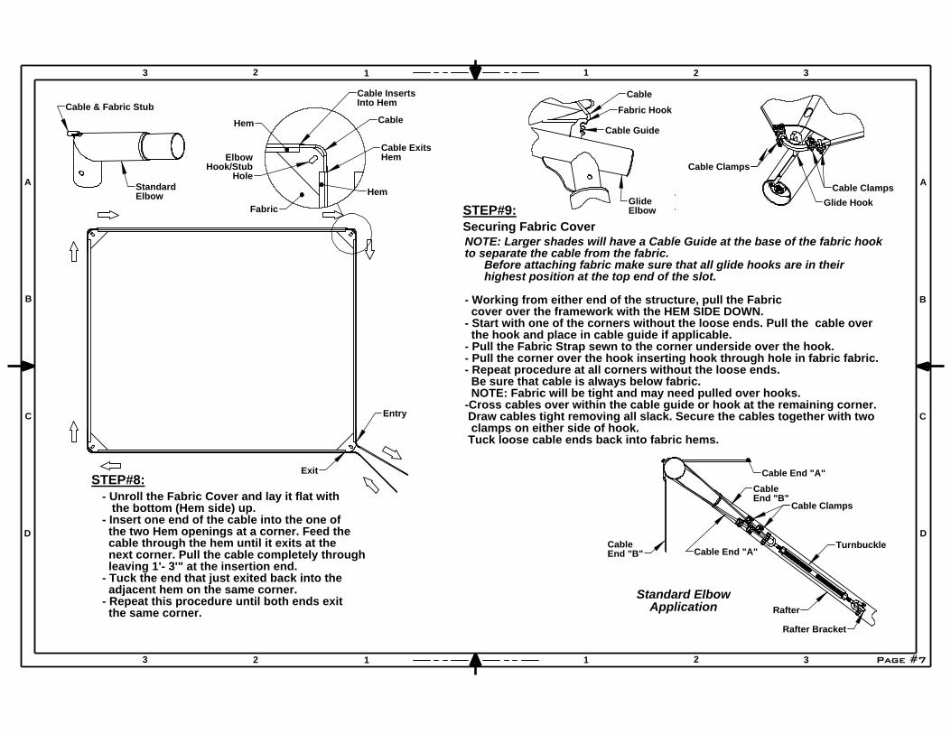
Cable
End "B" Cable End "A"
Rafter
Turnbuckle
End "B"
Cable
Cable End "A"
Cable Clamps
Rafter Bracket
Page #7
Glide Hook
Cable Clamps
Cable Clamps
Cable & Fabric Stub
StandardElbow
Securing Fabric Cover
Fabric Hook
Elbow
Cable
Standard ElbowApplication
STEP#9:Glide
Cable Guide
Hem
Into Hem
Cable Exits
Cable Inserts
Fabric
Hook/Stub
Hem Cable
Hole
Elbow
Hem
2 1 32
A
B
C
D
A
B
C
D
3 2 1 1 2 3
3 1
NOTE: Larger shades will have a Cable Guide at the base of the fabric hook to separate the cable from the fabric. Before attaching fabric make sure that all glide hooks are in their highest position at the top end of the slot.
- Working from either end of the structure, pull the Fabric cover over the framework with the HEM SIDE DOWN.- Start with one of the corners without the loose ends. Pull the cable over the hook and place in cable guide if applicable.- Pull the Fabric Strap sewn to the corner underside over the hook. - Pull the corner over the hook inserting hook through hole in fabric fabric.- Repeat procedure at all corners without the loose ends. Be sure that cable is always below fabric. NOTE: Fabric will be tight and may need pulled over hooks.-Cross cables over within the cable guide or hook at the remaining corner. Draw cables tight removing all slack. Secure the cables together with two clamps on either side of hook. Tuck loose cable ends back into fabric hems.
STEP#8:
the same corner. - Repeat this procedure until both ends exit adjacent hem on the same corner.
Entry
- Unroll the Fabric Cover and lay it flat with the bottom (Hem side) up.- Insert one end of the cable into the one of the two Hem openings at a corner. Feed the cable through the hem until it exits at the next corner. Pull the cable completely through leaving 1'- 3'" at the insertion end.- Tuck the end that just exited back into the
Exit
Page #8
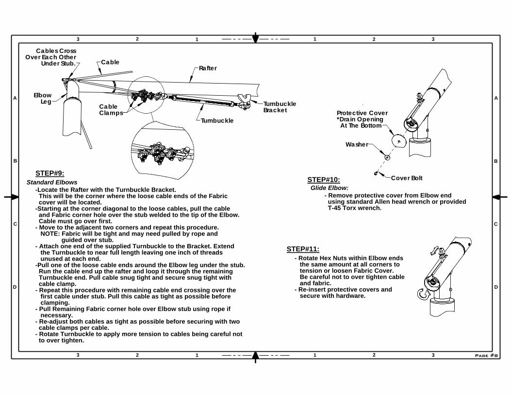
Washer
Cover BoltSTEP#10:
- Remove protective cover from Elbow end using standard Allen head wrench or provided T-45 Torx wrench.
Protective Cover*Drain Opening At The Bottom
32
A
B
C
D
A
B
C
D
3 2 1 1 2 3
3 2 1 1
secure with hardware.- Re-insert protective covers and
STEP#11:
Leg
cable clamps per cable.
Rafter
Glide Elbow:
Under Stub.Over Each Other
Clamps
- Pull Remaining Fabric corner hole over Elbow stub using rope if
Turnbuckle
Turnbuckle
necessary.
Cables Cross
Elbow
Standard ElbowsSTEP#9:
Bracket
to over tighten.
clamping.
Cable
Cable
- Re-adjust both cables as tight as possible before securing with two
- Rotate Turnbuckle to apply more tension to cables being careful not
-Locate the Rafter with the Turnbuckle Bracket. This will be the corner where the loose cable ends of the Fabric cover will be located.-Starting at the corner diagonal to the loose cables, pull the cable and Fabric corner hole over the stub welded to the tip of the Elbow. Cable must go over first.- Move to the adjacent two corners and repeat this procedure. NOTE: Fabric will be tight and may need pulled by rope and guided over stub.- Attach one end of the supplied Turnbuckle to the Bracket. Extend the Turnbuckle to near full length leaving one inch of threads unused at each end.-Pull one of the loose cable ends around the Elbow leg under the stub. Run the cable end up the rafter and loop it through the remaining Turnbuckle end. Pull cable snug tight and secure snug tight with cable clamp.- Repeat this procedure with remaining cable end crossing over the first cable under stub. Pull this cable as tight as possible before
- Rotate Hex Nuts within Elbow ends the same amount at all corners to tension or loosen Fabric Cover. Be careful not to over tighten cable and fabric.
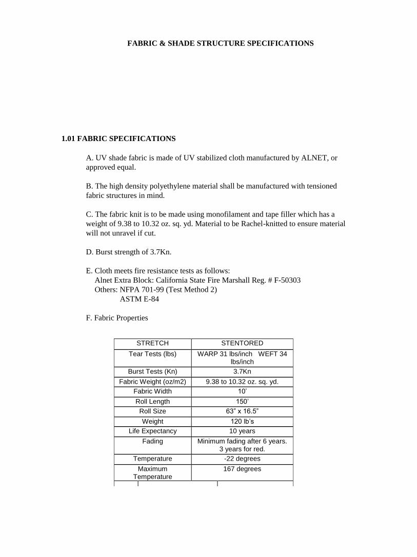
FABRIC & SHADE STRUCTURE SPECIFICATIONS
1.01 FABRIC SPECIFICATIONS
A. UV shade fabric is made of UV stabilized cloth manufactured by ALNET, or
approved equal.
B. The high density polyethylene material shall be manufactured with tensioned
fabric structures in mind.
C. The fabric knit is to be made using monofilament and tape filler which has a
weight of 9.38 to 10.32 oz. sq. yd. Material to be Rachel-knitted to ensure material
will not unravel if cut.
D. Burst strength of 3.7Kn.
E. Cloth meets fire resistance tests as follows:
Alnet Extra Block: California State Fire Marshall Reg. # F-50303
Others: NFPA 701-99 (Test Method 2)
ASTM E-84
F. Fabric Properties
STRETCH STENTORED
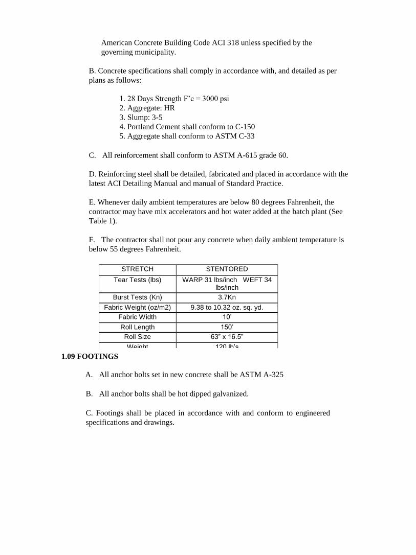
Tear Tests (lbs) WARP 31 lbs/inch WEFT 34 lbs/inch
Burst Tests (Kn) 3.7Kn
Fabric Weight (oz/m2) 9.38 to 10.32 oz. sq. yd.
Fabric Width 10’
Roll Length 150’
Roll Size 63” x 16.5”
Weight 120 lb’s
Life Expectancy 10 years
Fading Minimum fading after 6 years. 3 years for red.
Temperature -22 degrees
Maximum Temperature
167 degrees
N.3.1
Specific gravity 1.68+/- 0.05
N.3.2 Theoretical coverage 114+/- 4 ft2/lb/mil
N.3.3 Mass loss during cure < 1%
N.3.4 Maximum storage temp. 75 degrees F
ASTM
Gloss at 60 degree 85-95
HOI TM 10.219 PCI Powder smoothness 7
1.02 THREAD
A. Shall be 100% expanded PTFE fiber which carries an 8 year warranty that is high
strength and low shrinkage
B. Shall have a wide temperature and humidity range.
C. Abrasion resistant and UV radiation immunity.
1.03 STEEL TUBING
A. All fabricated steel must be in accordance with approved shop drawings and
calculations.
B. All steel is cleaned, degreased or etched to ensure proper adhesion of
powder-coat in accordance with manufacturer’s specifications.
C. All steel used on this project needs to be new and accompanied by the mill
certificates if requested. Structural steel tubing up to 5”-7gauge shall be galvanized
per Allied Steel FLO-COAT specifications. Schedule 40 black pipe fabrications
shall be sandblasted and primed as described below.
D. All non-hollow structural shapes comply with ASTM A-36, unless otherwise
noted.
E. All hollow structural steel shapes shall be cold formed HSS ASTM A-53 grade C,
unless otherwise noted.
F. Plate products shall comply with ASTM A-36.
D. Shall be unaffected by non-hydrocarbon based cleaning agents, acid rain,
mildew, rot, chlorine, saltwater, and pollution.
E. Lockstitch thread – 1200 Denier or equal.
F. Chainstitch thread – 2400 Denier or equal.
1.04 POWDER COATING & PRIMING
A. All non-galvanized steel shall be sandblasted and primed prior to powder
coating using G50 steel grit.
B. All non-galvanized steel must be coated with rust inhibiting primer prior to
applying the powder coat. Primer shall be Cardinal Industrial Finishes Corp. H304 –
GR312 Epoxy Polyester Hybrid Powder Coating Anti-gassing Primer.
C. Welds shall be primed with rust inhibiting primer prior to applying the powder
coat. Primer shall be Cardinal Industrial Finishes Corp H304 – GR312 Epoxy
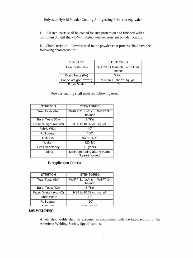
Polyester Hybrid Powder Coating Anti-gassing Primer or equivalent.
D. All steel parts shall be coated for rust protection and finished with a
minimum 3.5 mil thick UV-inhibited weather resistant powder coating.
E. Characteristics: Powder used in the powder-coat process shall have the
following characteristics:
Powder-coating shall meet the following tests:
F. Application Criteria
1.05 WELDING
A. All shop welds shall be executed in accordance with the latest edition of the
American Welding Society Specifications.
3
STRETCH STENTORED
Tear Tests (lbs) WARP 31 lbs/inch WEFT 34 lbs/inch
Burst Tests (Kn) 3.7Kn
Fabric Weight (oz/m2) 9.38 to 10.32 oz. sq. yd.
Fabric Width 10’
Roll Length 150’
Roll Size 63” x 16.5”
Weight 120 lb’s
Life Expectancy 10 years
Fading Minimum fading after 6 years. 3 years for red.
Temperature -22 degrees
Maximum Temperature
167 degrees
N.3.1
Specific gravity 1.68+/- 0.05
N.3.2 Theoretical coverage 114+/- 4 ft2/lb/mil
N.3.3 Mass loss during cure < 1%
N.3.4 Maximum storage temp. 75 degrees F
ASTM
Gloss at 60 degree 85-95
HOI TM 10.219 PCI Powder smoothness 7
ASTM D2454-91 Over-bake resistance time 200%
ASTM D3363-92A Pencil hardness H-2H
ASTM D 2794-93 Dir/Rev Impact, Gardner 140/140 in/lbs
ASTM D3359-95 B
Adhesion, cross hatch 5B Pass
ASTM D522-93A Flexibility Mandrel 1/4" dia, no fracture
ASTM B 117-95 Salt Spray 1,000 hours
UL DtOV2 Organic Coating Steel enclosures, elect eq. Recognized
N.5.1
Electrostatic spray cold Substrate: 0.032 in. CRS
N.5.2 Cure Schedule: 10 minutes at 400 0 F
N.5.3 Pretreatment Bonderite 1000
N.5.4 Film Thickness 3.5 Mils
Temperature Range
% Accelerator Type Accelerator
75-80 degrees 1% High Early (non calcium)
70-75 degrees 2% High Early (non calcium)
STRETCH STENTORED
Tear Tests (lbs) WARP 31 lbs/inch WEFT 34 lbs/inch
Burst Tests (Kn) 3.7Kn
Fabric Weight (oz/m2) 9.38 to 10.32 oz. sq. yd.
Fabric Width 10’
Roll Length 150’
Roll Size 63” x 16.5”
Weight 120 lb’s
Life Expectancy 10 years
Fading Minimum fading after 6 years. 3 years for red.
Temperature -22 degrees
Maximum Temperature
167 degrees
N.3.1
Specific gravity 1.68+/- 0.05
N.3.2 Theoretical coverage 114+/- 4 ft2/lb/mil
N.3.3 Mass loss during cure < 1%
N.3.4 Maximum storage temp. 75 degrees F
ASTM
Gloss at 60 degree 85-95
HOI TM 10.219 PCI Powder smoothness 7
ASTM D2454-91 Over-bake resistance time 200%
ASTM D3363-92A Pencil hardness H-2H
ASTM D 2794-93 Dir/Rev Impact, Gardner 140/140 in/lbs
ASTM D3359-95 B
Adhesion, cross hatch 5B Pass
ASTM D522-93A Flexibility Mandrel 1/4" dia, no fracture
ASTM B 117-95 Salt Spray 1,000 hours
UL DtOV2 Organic Coating Steel enclosures, elect eq. Recognized
N.5.1
Electrostatic spray cold Substrate: 0.032 in. CRS
STRETCH STENTORED
Tear Tests (lbs) WARP 31 lbs/inch WEFT 34 lbs/inch
Burst Tests (Kn) 3.7Kn
Fabric Weight (oz/m2) 9.38 to 10.32 oz. sq. yd.
Fabric Width 10’
Roll Length 150’
Roll Size 63” x 16.5”
Weight 120 lb’s
Life Expectancy 10 years
Fading Minimum fading after 6 years. 3 years for red.
Temperature -22 degrees
Maximum Temperature
167 degrees
N.3.1
Specific gravity 1.68+/- 0.05
N.3.2 Theoretical coverage 114+/- 4 ft2/lb/mil
N.3.3 Mass loss during cure < 1%
Maximum storage

B. Welding procedures shall comply in accordance with the AWS D1.1-AWS
Structural Welding Code-Steel.
C. All welds to be performed by a certified welder. All welds shall be continuous
where length is not given, unless otherwise shown or noted on drawings.
D. All welds shall develop the full strength of the weaker member. All welds
shall be made using E70xx.035 wire.
1.06 SEWING
A. On-site sewing of a fabric will not be accepted.
B. All corners shall be reinforced with extra non-tear cloth and strap to distribute
the load.
C. The perimeters that contain the cables shall be double lock stitched.
1.07 INSTALLATION HARDWARE
A. Bolt and fastening hardware shall be determined based on calculated
engineering loads.
B. All bolts shall comply with SAE-J429 (Grade 8) or ASTM A325 (Grade BD).
All nuts shall comply with ASTM F-594, alloy Group 1 or 2.
C. Wire rope cable shall be 7x19 strand galvanized wire rope with a breaking
strength of 7,000 lbs. (1/4” diameter) for shades generally under 1400 sq. ft. unless
requested larger by the customer. For shades >1400 sq. ft. cable shall be 5/16”
@9800# breaking strength.
D. All fittings required for proper securing of the cable are hot dipped galvanized.
F. All fillet welds shall be a minimum of ¼” unless otherwise noted.
G. All steel shall be welded shut at terminations to prevent internal leakage.
H. Internal weld sleeving is not acceptable.
I. On-site welding of any component is not acceptable.
E. Shop connections shall be welded unless noted otherwise. Field connections
shall be indicated on the drawings. Field –welded connections are not acceptable.
1.08 CONCRETE
A. Concrete work shall be executed in accordance with the latest edition of
American Concrete Building Code ACI 318 unless specified by the
governing municipality.
B. Concrete specifications shall comply in accordance with, and detailed as per
plans as follows:
1. 28 Days Strength F’c = 3000 psi
2. Aggregate: HR
3. Slump: 3-5
4. Portland Cement shall conform to C-150
5. Aggregate shall conform to ASTM C-33
C. All reinforcement shall conform to ASTM A-615 grade 60.
D. Reinforcing steel shall be detailed, fabricated and placed in accordance with the
latest ACI Detailing Manual and manual of Standard Practice.
E. Whenever daily ambient temperatures are below 80 degrees Fahrenheit, the
contractor may have mix accelerators and hot water added at the batch plant (See
Table 1).
F. The contractor shall not pour any concrete when daily ambient temperature is
below 55 degrees Fahrenheit.
A. All anchor bolts set in new concrete shall be ASTM A-325
1.09 FOOTINGS
B. All anchor bolts shall be hot dipped galvanized.
C. Footings shall be placed in accordance with and conform to engineered
specifications and drawings.
STRETCH STENTORED
Tear Tests (lbs) WARP 31 lbs/inch WEFT 34 lbs/inch
Burst Tests (Kn) 3.7Kn
Fabric Weight (oz/m2) 9.38 to 10.32 oz. sq. yd.
Fabric Width 10’
Roll Length 150’
Roll Size 63” x 16.5”
Weight 120 lb’s
Life Expectancy 10 years
Fading Minimum fading after 6 years. 3 years for red.
Temperature -22 degrees
Maximum Temperature
167 degrees
N.3.1
Specific gravity 1.68+/- 0.05
N.3.2 Theoretical coverage 114+/- 4 ft2/lb/mil
N.3.3 Mass loss during cure < 1%
N.3.4 Maximum storage temp. 75 degrees F
ASTM
Gloss at 60 degree 85-95
HOI TM 10.219 PCI Powder smoothness 7
ASTM D2454-91 Over-bake resistance time 200%
ASTM D3363-92A Pencil hardness H-2H
ASTM D 2794-93 Dir/Rev Impact, Gardner 140/140 in/lbs
ASTM D3359-95 B
Adhesion, cross hatch 5B Pass
ASTM D522-93A Flexibility Mandrel 1/4" dia, no fracture
ASTM B 117-95 Salt Spray 1,000 hours