Embed Size (px)
Citation preview
HILGE sanitary pumps50 Hz
Sanitary pumps 50Hz

2
Contents
IntroductionHilge sanitary pumps 3Hygienic design 3
Performance rangePerformance range, 2-pole 4Performance range, 4-pole 4
Euro-HYGIA®Euro-HYGIA®s 6
ContraContra 8
SIPLASIPLA 10
MAXA and MAXANAMAXA and MAXANA 12
Product dataProduct range, 50 Hz 14
IdentificationType keys 15
ConstructionMotor 16Impeller types 19Surface treatment 19
Shaft sealsMechanical shaft seal 20
CertificationApprovals and certificates 21Certificates 21Surface finish of hygienic pumps 22
Designs and versionsDesign variations 23Housing sealing for Euro-HYGIA pumps 26
Standard pipe connectionsEuro-HYGIA® I 27Euro-HYGIA® II 28Contra I 29Contra II 32MAXA 35MAXANA 36
InstallationMechanical installation 37Space requirements 37Foundation and vibration dampening 38Terminal box positions 38
Curve chartsHow to read the curve charts 39Curve conditions 40
Performance curves/ Technical dataEuro-HYGIA® I 41Euro-HYGIA® II 47Contra I 56Contra II 63SIPLA 70MAXA 76MAXA L 85MAXANA 90
Further product documentationWebCAPS 106

3
Sanitary pumps50 HzIntroduction
Hilge sanitary pumpsStainless steel sanitary pumps designed for a wide rangeof hygienic and sanitary applications such as
• breweries
• beverage industry
• dairies
• food industry
• pharmaceutical industry
• biotechnology industry
• cosmetics industry
• water treatment systems
• semi-conductor industry
• textile industry.
The Hilge range of sanitary pumps comprises the belowpumps types - each state-of-the-art within its specificfield of application. The pumps can be fitted with avariety of features to adapt to specific pumping tasks.In addition, it is possible to customise the pumps foroptimum function or performance in relation to the jobat hand.
Euro-HYGIA®
Euro-HYGIA® pumps are all single-stage, end-suctioncentrifugal pumps. The pumps offer heads up to 70metres, flow rates up to 108 m3/h and an operating pres-sures up to 16 bar. Pipe connections range from DN 25 toDN 125 and the motor sizes from 0.55 to 22 kW. For further information, see page 6.
Contra
Contra pumps are single-stage or multistage, end-suction centrifugal pumps. The pumps offer heads up to160 metres, flow rates up to 55 m3/h and operating pres-sures up to 25 bar. Pipe connections range from DN 25 toDN 80 and motor sizes from 0.55 to 18.5 kW. For further information, see page 8.
SIPLA
SIPLA pumps are all single-stage, self-priming side-channel pumps. The pumps offer heads up to 56 metres,flow rates up to 80 m3/h and operating pressures up to10 bar. Pipe connections range from DN 32 to DN 80 andmotor sizes from 0.55 to 22 kW.For further information, see page 10.
MAXA
MAXA pumps are all single-stage, end-suction centrif-ugal pumps. MAXA pumps are designed according toDIN EN 733. The pumps offer heads up to 97 metres, flowrates up to 820 m3/h and operating pressures up to 10bar. Pipe connections range from DN 80 to DN 150 andmotor sizes from 7.5 to 90 kW. For further information, see page 12.
MAXANA
MAXANA pumps are all single-stage, end-suctioncentrifugal pumps. MAXANA pumps are designedaccording to DIN EN 733. The pumps offer heads up to 97metres, flow rates up to 165 m3/h and operating pres-sures up to 10 bar. Pipe connections range from DN 32 toDN 80 and motor sizes from 2.2 to 55 kW.For further information, see page 12.
Hygienic designThe Hilge sanitary pumps have been designed in accord-ance with the strictest hygienic design criteria.The surface finish of the materials used is of the utmostimportance - both for physical properties and withregard to preventing possible breeding grounds forbacteria and germs.Fully drainable models are available, and the use of AISI316L (DIN EN 1.4404/1.4435) cold-rolled and/or forgedstainless steel ensures a homogeneous pore-freesurface, in contrast to cast materials.
The design requirements and materials used as well asmaterial surface finish are subject to a variety ofnational and international rules and regulations, guide-lines and laws. Among these are the EU machinery direc-tive, GMP Rules and Regulations, FDA Regulations, 3Asanitary standard, EU Foodstuff Hygienic Guidelines,DIN EN 12462 Biotechnology, the recommendations ofthe EHEDG (European Hygienic Equipment DesignGroup) and QHD (Qualified Hygienic Design).
Shaft seals
Depending on the application and pumped liquid, singleor double mechanical shaft seal arrangements are avail-able to ensure trouble-free operation.Double seal arrangements are offered as either atandem or back-to-back seal arrangement.
The single shaft seals used are inboard mechanical sealswith an optimum position in the pumped liquid in orderto ensure lubrication, cooling as well as CIP (Cleaning-In-Place) and SIP (Sterilisation-In-Place). Standard sealshave seal faces of carbon/stainless steel and O-rings ofEPDM. Other seal face material combinations are avail-able on request.
Connections
A variety of connections are available. These includesterile threads to DIN 11864-1 PN 16 and sterile flangesto DIN 11864-2 PN 16.Other connections such as SMS, RJT, DIN or ISO clampconnections and Tri-Clover are available on request.
Special sterile threaded fittings and flanges can also besupplied.
4
Sanitary pumps50 Hz
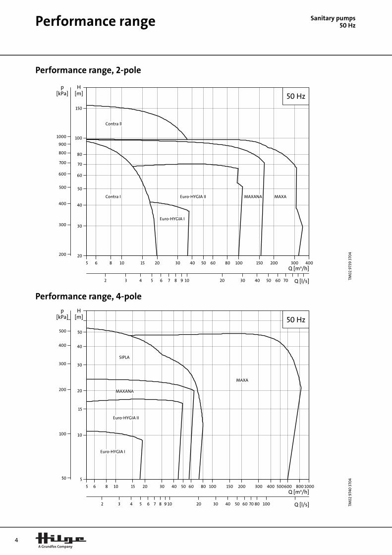
Performance rangePerformance range, 2-pole
Performance range, 4-pole
TM0
2 9
739
370
4TM
02
974
0 3
704
5 6 8 10 15 20 30 40 50 60 80 100 150 200 300 400Q [m³/h]
20
30
40
50
60
70
80
100
150
[m]H
2 3 4 5 6 7 8 9 1010 20 30 40 50 60 70 Q [l/s]
200
300
400
500
600
700
800
900
10001000
[kPa]p
50 Hz
Contra ll
Euro-HYGIA I
Contra I Euro-HYGIA II MAXANA MAXA
5 6 8 10 15 20 30 40 50 60 80 100 150 200 300 400 500600 800 1000Q [m³/h]
5
10
15
20
30
40
50
[m]H
2 3 4 5 6 7 8 9 1010 20 30 40 50 60 70 80 100100 Q [l/s]
50
100100
200
300
400
500
[kPa]p
50 Hz
Euro-HYGIA I
Euro-HYGIA II
SIPLA
MAXA
MAXANA

5

6
Sanitary pumps50 Hz
Euro-HYGIA®Euro-HYGIA®s
Fig. 1 Euro-HYGIA®
Technical data
Euro-HYGIA® I and II
Head: up to 70 m
Flow rate: up to 108 m3/h(Euro-HYGIA® III - on request): up to 250 m3/h
Operating pressure: up to 16 bar
Operating temperature: 95°C (up to 150°C on request)
Sterilisation temperature: 140°C (SIP)
ApplicationsThe unique hygienic design and the use of materialsmake the Euro-HYGIA® pump range suitable for:
Food and beverage industry
• Liquid transfer in breweries and dairies
• Mixing in soft drink applications
• Food processing plants.
Pharmaceutical industry
• Pure water systems (WFI)
• Biotechnology
• Cosmetics.
Other industrial applications
• Semi-conductor manufacturing
• CIP (Cleaning-In-Place) systems.
ConstructionEuro-HYGIA® pumps are single-stage, end-suctioncentrifugal pumps designed to meet the hygienicrequirements of sterile process technology. The pumpsare CIP and SIP capable in compliance with the DIN EN12462 performance criteria.
The design of the wetted parts meets the Qualified Hygi-enic Design (QHD) standard, EHEDG test certificate forCIP cleanability (TNO), 3A sanitary standard (USA) andGOST (Russia).
The pump housing is made of heavy-duty, rolled anddeep-drawn CrNiMo steel DIN EN 1.4404/1.4435, equiva-lent to AISI 316L.
Three impeller types are available depending on theapplication: Semi-open, closed and free-flow impeller.For further information, see page 19.
The pumps have a mechanical shaft seal and a fan-cooled asynchronous motor with enclosure class IP 55.
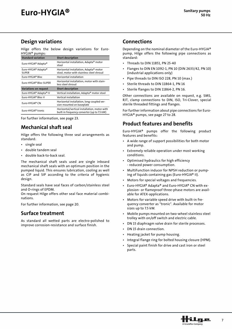
Fig. 2 Sectional drawing of Euro-HYGIA® I Bloc-SUPER on combi-foot
Materials
GR
896
3
TM0
2 9
60
7 35
04
Pos. Component Material DIN EN
1 Impeller CrNiMo steel1.4404/1.4435
2 Pump housing CrNiMo steel1.4404/1.4435
3 Shaft sealSterile applications: SiC/SiC/EPDMHygienic applications: Carbon/stainless steel/EPDM or FKM
4 Pump shaft CrNiMo steel 1.4571
5 Motor
6 Shroud Stainless steel
7 Support Stainless steel/cast iron
1 4 5 6
2 3 7
Euro-HYGIA® S
anitary pumps50 HzDesign variationsHilge offers the below design variations for Euro-HYGIA® pumps:
For further information, see page 23.
Mechanical shaft sealHilge offers the following three seal arrangements asstandard:
• single seal
• double tandem seal
• double back-to-back seal.
The mechanical shaft seals used are single inboardmechanical shaft seals with an optimum position in thepumped liquid. This ensures lubrication, cooling as wellas CIP and SIP according to the criteria of hygienicdesign.
Standard seals have seal faces of carbon/stainless steeland O-rings of EPDM.On request Hilge offers other seal face material combi-nations.
For further information, see page 20.
Surface treatmentAs standard all wetted parts are electro-polished toimprove corrosion-resistance and surface finish.
ConnectionsDepending on the nominal diameter of the Euro-HYGIA®pump, Hilge offers the following pipe connections asstandard:
• Threads to DIN 11851, PN 25-40
• Flanges to DIN EN 1092-1, PN 10 (DIN 2633/42, PN 10)(industrial applications only)
• Pipe threads to DIN ISO 228, PN 10 (max.)
• Sterile threads to DIN 11864-1, PN 16
• Sterile flanges to DIN 11864-2, PN 16.
Other connections are available on request, e.g. SMS,RJT, clamp connections to DIN, ISO, Tri-Clover, specialsterile threaded fittings and flanges.
For further information about pipe connections for Euro-HYGIA® pumps, see page 27 to 28.
Product features and benefitsEuro-HYGIA® pumps offer the following productfeatures and benefits:
• A wide range of support possibilities for both motor and pump.
• Extremely reliable operation under most working conditions.
• Optimised hydraulics for high efficiency- reduced power consumption.
• MultiFunction inducer for NPSH reduction or pump-ing of liquids containing gas (Euro-HYGIA® II).
• Motors for special voltages and frequencies.
• Euro-HYGIA® Adapta® and Euro-HYGIA® CN with ex-plosion- or flameproof three-phase motors are avail-able for ATEX-applications.
• Motors for variable speed drive with built-in fre-quency converter as "tronic". Available for motor sizes up to 7.5 kW.
• Mobile pumps mounted on two-wheel stainless steel trolley with on/off switch and electric cable.
• DN 15 diaphragm valve drain for sterile processes.
• DN 15 drain connection.
• Heating jacket for pump housing.
• Integral flange ring for bolted housing closure (HPM).
• Special paint finish for drive and cast iron or steel parts.
Standard variation Short description
Euro-HYGIA® Adapta®Horizontal installation, Adapta® motor stool
Euro-HYGIA® Adapta® SUPER
Horizontal installation, Adapta® motor stool, motor with stainless steel shroud
Euro-HYGIA® Bloc Horizontal installation
Euro-HYGIA® Bloc-SUPERHorizontal installation, motor with stain-less steel shroud
Variations on request Short description
Euro-HYGIA® Adapta®-V Vertical installation, Adapta® motor stool
Euro-HYGIA® Bloc-V Vertical installation
Euro-HYGIA® CNHorizontal installation, long-coupled ver-sion mounted on baseplate
Euro-HYGIA® tronicHorizontal/vertical installation, motor with built-in frequency converter (up to 7.5 kW)
7
8
Sanitary pumps50 Hz
ContraContra
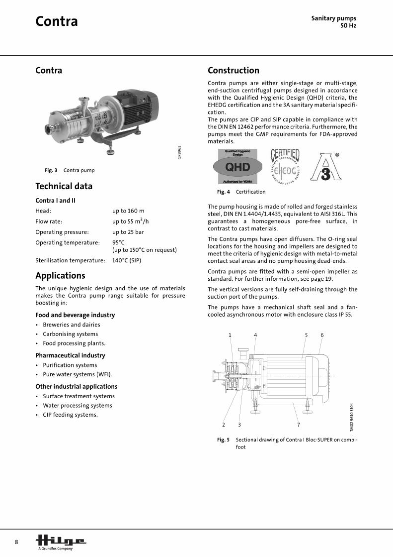
Fig. 3 Contra pump
Technical data
Contra I and II
Head: up to 160 m
Flow rate: up to 55 m3/h
Operating pressure: up to 25 bar
Operating temperature: 95°C (up to 150°C on request)
Sterilisation temperature: 140°C (SIP)
ApplicationsThe unique hygienic design and the use of materialsmakes the Contra pump range suitable for pressureboosting in:
Food and beverage industry
• Breweries and dairies
• Carbonising systems
• Food processing plants.
Pharmaceutical industry
• Purification systems
• Pure water systems (WFI).
Other industrial applications
• Surface treatment systems
• Water processing systems
• CIP feeding systems.
ConstructionContra pumps are either single-stage or multi-stage,end-suction centrifugal pumps designed in accordancewith the Qualified Hygienic Design (QHD) criteria, theEHEDG certification and the 3A sanitary material specifi-cation. The pumps are CIP and SIP capable in compliance withthe DIN EN 12462 performance criteria. Furthermore, thepumps meet the GMP requirements for FDA-approvedmaterials.
Fig. 4 Certification
The pump housing is made of rolled and forged stainlesssteel, DIN EN 1.4404/1.4435, equivalent to AISI 316L. Thisguarantees a homogeneous pore-free surface, incontrast to cast materials.
The Contra pumps have open diffusers. The O-ring seallocations for the housing and impellers are designed tomeet the criteria of hygienic design with metal-to-metalcontact seal areas and no pump housing dead-ends.
Contra pumps are fitted with a semi-open impeller asstandard. For further information, see page 19.
The vertical versions are fully self-draining through thesuction port of the pumps.
The pumps have a mechanical shaft seal and a fan-cooled asynchronous motor with enclosure class IP 55.
Fig. 5 Sectional drawing of Contra I Bloc-SUPER on combi-foot
GR
896
1
TM0
2 9
610
350
4
1 4 5 6
2 3 7
Contra S
anitary pumps50 HzMaterials
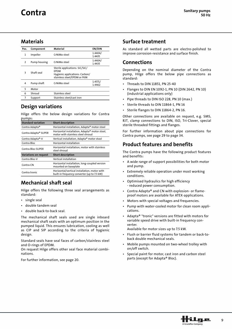
Design variationsHilge offers the below design variations for Contrapumps:
Mechanical shaft sealHilge offers the following three seal arrangements asstandard:
• single seal
• double tandem seal
• double back-to-back seal.
The mechanical shaft seals used are single inboardmechanical shaft seals with an optimum position in thepumped liquid. This ensures lubrication, cooling as wellas CIP and SIP according to the criteria of hygienicdesign.
Standard seals have seal faces of carbon/stainless steeland O-rings of EPDM.On request Hilge offers other seal face material combi-nations.
For further information, see page 20.
Surface treatmentAs standard all wetted parts are electro-polished toimprove corrosion-resistance and surface finish.
ConnectionsDepending on the nominal diameter of the Contrapump, Hilge offers the below pipe connections asstandard:
• Threads to DIN 11851, PN 25-40
• Flanges to DIN EN 1092-1, PN 10 (DIN 2642, PN 10)(industrial applications only)
• Pipe threads to DIN ISO 228, PN 10 (max.)
• Sterile threads to DIN 11864-1, PN 16
• Sterile flanges to DIN 11864-2, PN 16.
Other connections are available on request, e.g. SMS,RJT, clamp connections to DIN, ISO, Tri-Clover, specialsterile threaded fittings and flanges.
For further information about pipe connections forContra pumps, see page 29 to page 34.
Product features and benefitsThe Contra pumps have the following product featuresand benefits:
• A wide range of support possibilities for both motor and pump.
• Extremely reliable operation under most working conditions.
• Optimised hydraulics for high efficiency- reduced power consumption.
• Contra Adapta® and CN with explosion- or flame-proof motors are available for ATEX-applications.
• Motors with special voltages and frequencies.
• Pump with water-cooled motor for clean room appli-cations.
• Adapta® "tronic" versions are fitted with motors for variable speed drive with built-in frequency con-verter. Available for motor sizes up to 7.5 kW.
• Flush or barrier fluid systems for tandem or back-to-back double mechanical seals.
• Mobile pumps mounted on two-wheel trolley with on/off switch.
• Special paint for motor, cast iron and carbon steel parts (except for Adapta® Bloc).
Pos. Component Material EN/DIN
1 Impeller CrNiMo steel1.4404/1.4435
2 Pump housing CrNiMo steel1.4404/1.4435
3 Shaft seal
Sterile applications: SiC/SiC/EPDMHygienic applications: Carbon/stainless steel/EPDM or FKM
4 Pump shaft CrNiMo steel1.4571/1.4462
5 Motor
6 Shroud Stainless steel
7 Support Stainless steel/cast iron
Standard variation Short description
Contra Adapta® Horizontal installation, Adapta® motor stool
Contra Adapta® SUPERHorizontal installation, Adapta® motor stool, motor with stainless steel shroud
Contra Adapta®-V Vertical installation, Adapta® motor stool
Contra Bloc Horizontal installation
Contra Bloc-SUPERHorizontal installation, motor with stainless steel shroud
Variations on request Short description
Contra Bloc-V Vertical installation
Contra CNHorizontal installation, long-coupled version mounted on baseplate
Contra tronicHorizontal/vertical installation, motor with built-in frequency converter (up to 7.5 kW)
9

10
Sanitary pumps50 Hz
SIPLASIPLA
Fig. 6 SIPLA pump
Technical data
SIPLA pumps
Head: up to 56 m
Flow rate: up to 80 m3/h
Operating pressure: up to 10 bar
Operating temperature: 95°C
Sterilisation temperature: 140°C (SIP)
ApplicationsThe unique hygienic design, the use of materials and theexceptional self-priming capability make the SIPLApump range suitable for:
Food and beverage industry
• Transfer of yeast
• Transfer of cheese whey.
Pharmaceutical industry
• Transfer of glycerine.
Other industrial applications
• CIP returned pumping.
ConstructionSIPLA pumps are single-stage, self-priming side-channelpumps designed in accordance with the 3A sanitarystandard.
Fig. 7 Certification
The pump housing and front cover are made of precisioncast stainless steel DIN EN 1.4404 and the impeller nut ofstainless steel DIN EN 1.4435, equivalent to AISI 316L.
SIPLA pumps are fitted with an open star impeller asstandard.
The pump shaft is made of stainless steel DIN EN 1.4571(equal to AISI 316TI).
Thanks to its unique side-channel design, the SIPLApump is capable of handling liquids with a high contentof air as in CIP return systems.
The pumps have a mechanical shaft seal and a fan-cooled asynchronous motor with enclosure class IP 55.
Fig. 8 Sectional drawing of SIPLA Bloc-SUPER on stainless steel ball feet
Materials
GR
896
5
TM0
2 9
60
8 35
04
Pos. Component Material EN/DIN
1 Impeller CrNiMo steel 1.4404
2 Pump housing CrNiMo steel 1.4404
3 Shaft sealHygienic applications: Carbon/stainless steel /EPDM or FKM
4 Pump shaft CrNiMo steel 1.4571
5 Motor
6 Shroud Stainless steel
7 Support Stainless steel/cast iron
2 4 5 6
1 7 3 7

SIPLA S
anitary pumps50 HzDesign variationsHilge offers the below design variations for SIPLApumps:
For further information, see page 24.
Mechanical shaft sealSIPLA pumps are fitted with a single inboard mechanicalshaft seal with an optimum position in the pumpedliquid that ensuring efficient CIP, SIP, cooling and lubri-cation.
As standard Hilge offers a shaft seal with seal faces ofcarbon/stainless steel and O-rings of either EPDM orFKM.
On request Hilge offers shaft seals with seal faces ofsilicon carbide/silicon carbide and an O-ring of EPDM orFKM.
For further information, see page 20.
Surface treatmentAs standard all wetted parts are electro-polished toimprove corrosion-resistance and surface finish.
ConnectionsDepending on the nominal diameter of the SIPLA pump,Hilge offers threaded pipe connections according to DIN11851.
Optional connections are threaded connections: SMS,RJT, IDF clamp connections to DIN and clamps Tri-Clamp/Tri-Clover.
Product features and benefitsThe SIPLA pumps have the following product featuresand benefits:
• A wide range of support possibilities for both motor and pump.
• Extremely reliable operation under most working conditions.
• Optimised hydraulics for high efficiency- reduced power consumption.
• Motors for variable speed drive with built-in fre-quency converter, "tronic". Available for motor sizes up to 7.5 kW.
• ATEX-certified pumps available on request.
Standard variation Short description
SIPLA Adapta® SUPERHorizontal installation, Adapta® motor stool, motor with stainless steel shroud
SIPLA Bloc Horizontal installation
SIPLA Bloc-SUPERHorizontal installation, motor with stain-less steel shroud
Variations on request Short description
SIPLA CNHorizontal installation, long-coupled ver-sion mounted on baseplate
SIPLA tronicHorizontal/vertical installation, motor with built-in frequency converter (up to 7.5 kW)
11

12
Sanitary pumps50 Hz
MAXA and MAXANAMAXA and MAXANA
Fig. 9 MAXANA and MAXA pumps
Technical data
MAXA pumps
Head: 97 m
Flow rate: up to 820 m3/h
Operating pressure: up to 10 bar
Operating temperature: 95°C (up to 150°C on request)
Sterilisation temperature: 140°C (SIP)
MAXANA pumps
Head: up to 97 m
Flow rate: up to 165 m3/h
Operating pressure: up to 10 bar
Operating temperature: 95°C (up to 150°C on request)
Sterilisation temperature: 140°C (SIP)
ApplicationsThe MAXA and MAXANA pumps meet the requirements:
The MAXA and MAXANA pump ranges are suitable for:
Food and beverage industry
• Gentle pumping of mash and wort, and beer filtra-tion (hot side)
• Dairies
• Food processing.
Other industrial applications
• Water treatment plants
• Chemical handling systems
• Liquids with a high content of solid particles.
ConstructionThe MAXA and MAXANA pumps are single-stage, end-suction centrifugal pumps designed for heavy-dutyoperation in industrial processes. The major dimensions and characteristics of thesepumps correspond to DIN EN 733 and DIN EN 22858.
The pump housing are made of heavy-duty, rolled anddeep-drawn stainless steel in quality DIN EN 1.4404. Theback plate is made of rolled stainless steel DIN EN 1.4571.
The pumps feature closed impellers with optimisedblade entry angles made of steel quality DIN EN 1.4571.For further information about impeller types, seepage 19.
Fig. 10 Sectional drawing of MAXANA-CN on baseplate
TM0
3 0
170
430
4
Pump type Standard
MAXANA 3A0
MAXA 3A0, 3A1 and 3A2
TM0
2 9
60
9 3
504
2 5 4 6 7
1 3 8

MAXA and MAXANA S
anitary pumps50 HzMaterials
Design variationsHilge offers the below design variations for MAXA andMAXANA pumps:
For further information, see page 25.
Mechanical shaft sealHilge offers the following three seal arrangements asstandard:
• single seal
• double tandem seal
• double back-to-back seal.
As standard MAXA and MAXANA pumps are fitted witha single inboard mechanical shaft seal with an optimumposition in the pumped liquid ensuring efficientcleaning, cooling and lubrication.
The mechanical shaft seal is in accordance with DIN EN12756.
Standard seals have seal faces of carbon/stainless steeland O-rings of EPDM.On request Hilge offers other seal face material combi-nations.
For further information, see page 20.
Surface treatmentAs standard all wetted parts are made of corrosion-resistant chrome-nickel-molybdenum steel.
Hilge offers industrial variants that are electro-polished.
ConnectionsDepending on the nominal diameter of the MAXA andMAXANA pumps, Hilge offers a standard flangedconnection according to DIN EN 1092-1, PN 10 (DIN 2632,PN 10).
Optional connections include connections in accordancewith ANSI and JIS standards.
Product features and benefitsThe MAXA and MAXANA pumps have the followingproduct features and benefits:
• A wide range of support possibilities for both motor and pump.
• Extremely reliable operation under most working conditions.
• Optimised hydraulics for high efficiency- reduced power consumption.
• On request the pumps are available with the dis-charge port positioned at the top, to the right or to the left.
• Double mechanical seals, depending on model, either with flushing or barrier fluid.
• Packed gland as shaft seal, single or flushed with C-bearing support to DIN EN 22858 and shaft sleeve.
• Motors with special voltages and frequencies.
• Adapta® and CN available with a flameproof three-phase motor for ATEX-applications.
• Motors for variable speed drive with built-in fre-quency converter as "tronic". Available for motor sizes up to 7.5 kW.
• Housing drain connection DN 15; other sizes availa-ble.
• Housing with heating jacket.
• Special paint for motor and steel components.
• MAXA Adapta® and MAXANA Adapta® pumps availa-ble with trolley.
Pos. Component Material EN/DIN
1 Impeller CrNiMo steel1.4404/1.4435
2 Pump housing CrNiMo steel1.4404/1.4435
3 Shaft seal
Sterile applications: SiC/SiC/EPDMHygienic applications: Carbon/stainless steel/EPDM or FKM
4 Pump shaft CrNiMo steel1.4401/1.4571
5 Bearing bracket Stainless steel
6 Coupling
7 Motor
8 Baseplate Stainless steel
Standard variation Short description
MAXA L Horizontal installation
MAXA CNHorizontal installation, mounted on base-plate
MAXANA Adapta®Horizontal installation, Adapta® motor stool
MAXANA Bloc Horizontal installation
Variations on request Short description
MAXA DINHorizontal installation, mounted on base-plate
MAXA CNHorizontal installation, mounted on base-plate
MAXA Bloc Horizontal installation
MAXA tronicHorizontal installation, motor with built-in frequency converter (up to 7.5 kW)
MAXANA CNHorizontal installation, mounted on base-plate
MAXANA LHorizontal installation, mounted on pump foot or motor foot
MAXANA tronicHorizontal installation, motor with built-in frequency converter (up to 7.5 kW)
13

14
Sanitary pumps50 HzProduct data
Product range, 50 Hz
Pump range
Euro
-H
YGIA
I
Euro
-H
YGIA
II
Co
ntr
a I
Co
ntr
a II
SIPL
A 3
.1
SIPL
A 6
.1
SIPL
A 1
2.1
SIPL
A 1
8.1
SIPL
A 2
8.1
SIPL
A 5
2.1
SIPL
A 6
5.1
SIPL
A 9
0.1
MA
XA
MA
XA
NA
Hydraulic data
Max. head [m] 43 70 105 160 23 34 25 28 38 36 56 44 98 98
Flow rate [m3/h] 0-39 0-108 0-23 0-53 0-4.5 0-6 0-12 0-18 0-26 0-42 0-65 0-80 20-800 0-165
Max. operating temperature [°C] 95 95 95 95 95 95 95 95 95 95 95 95 95 95
Max. temperature [°C]– on request
150 150 140 140 140 140 140 140 140 140 140 140 150 150
Max. operating presssure [bar] 16 16 25 25 10 10 10 10 10 10 10 10 10 10
Max. pump efficiency [%] 62 68 55 62 16.5 18.5 24 24 29 30 34 35 87 72
Motor data
Motor power [kW] 0.55-5.5 0.75-22 0.55-5.50.75-18.5
0.55-0.75
1.5-2.2 1.5-2.2 3-4 4-5.5 7.5-11 11-15 18.5-22 3-90 0.55-55
Design
Bloc
Bloc SUPER
Bloc-V
Adapta®
Adapta® SUPER
Adapta®-V
CN
L
Tronic version
Materials
Pump housing:CrNiMo stainless steel 1.4404
Pump housing:Stainless steel 1.4404/1.4435
Pipe connection
Threads, DIN 11851, PN 25-40
Threads, DIN ISO 228, PN 10
Sterile threads, DIN 11864-1, PN 16
Flanges, DIN EN 1092-1(DIN 2632)
Flanges, DIN EN 1092-1(DIN 2642)
Sterile flanges, DIN 11864-2, PN 16
SMS
RJT
DIN clamp connection
Clamps Tri-Clover/Tri-Clamp
Special sterile threaded fittings and flanges
Impeller types
Semi-open
Closed
Two-channel (closed)
Free-flow
Standard.
Available on request.
SIPLA 90.1 pumps offer flow rates up to 90 m3/h - on request.
Euro-HYGIA® II pumps offer flow rates up to 130 m3/h - on request. Euro-HYGIA® III pumps offer flow rates up to 250 m3/h - on request.
For information about pipe connection, see page 27.
For industrial applications only.
15
Sanitary pumps50 HzIdentification
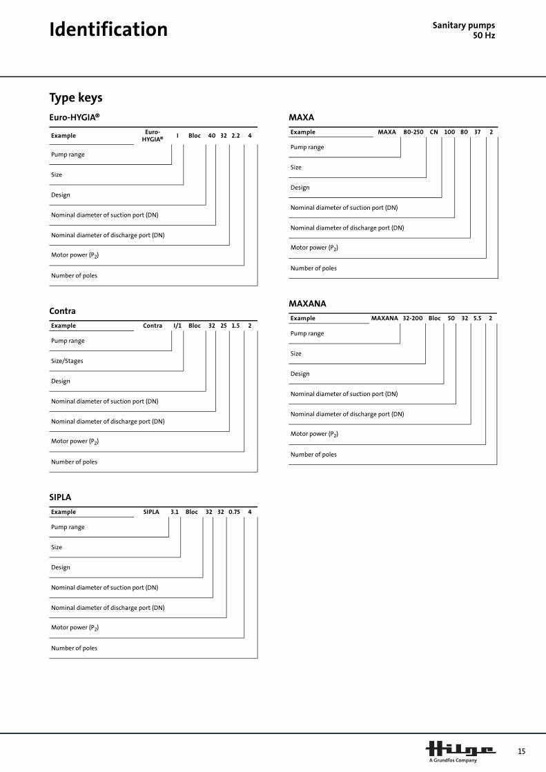
Type keys
Euro-HYGIA®
Contra
SIPLA
MAXA
MAXANA
ExampleEuro-
HYGIA®I Bloc 40 32 2.2 4
Pump range
Size
Design
Nominal diameter of suction port (DN)
Nominal diameter of discharge port (DN)
Motor power (P2)
Number of poles
Example Contra I/1 Bloc 32 25 1.5 2
Pump range
Size/Stages
Design
Nominal diameter of suction port (DN)
Nominal diameter of discharge port (DN)
Motor power (P2)
Number of poles
Example SIPLA 3.1 Bloc 32 32 0.75 4
Pump range
Size
Design
Nominal diameter of suction port (DN)
Nominal diameter of discharge port (DN)
Motor power (P2)
Number of poles
Example MAXA 80-250 CN 100 80 37 2
Pump range
Size
Design
Nominal diameter of suction port (DN)
Nominal diameter of discharge port (DN)
Motor power (P2)
Number of poles
Example MAXANA 32-200 Bloc 50 32 5.5 2
Pump range
Size
Design
Nominal diameter of suction port (DN)
Nominal diameter of discharge port (DN)
Motor power (P2)
Number of poles

16
Sanitary pumps50 Hz
ConstructionMotorThe motor is a totally enclosed, fan-cooled standardmotor with main dimensions to IEC and DIN standards.Electrical tolerances to IEC 34.
Mounting designation
Relative humidity: Max. 95%
Enclosure class: IP 55
Insulation class: F, to IEC 85
Ambient temperature: Max. 40°C
In humid locations, the lowest drain hole in the motormust be opened. In such cases the motor enclosure classis IP 44.
Motor ranges
Euro-HYGIA® I
Euro-HYGIA® II
Contra I
Contra II
SIPLA
Pump rangeMounting designation - IEC 34-7
Horizontal installation Vertical installation
Euro-HYGIA®
IM 1001 (IM B3)IM 3001 (IM B5)
IM 2001 (IM B35)
IM 1011 (IM V5)IM 3011 (IM V1)
IM 2011 (IM V15)
Contra
SIPLA
MAXA
MAXANA
P2 kW 2-pole 4-pole
0.55
0.75
1.1
1.5
2.2
3.0
4.0
5.5
The grey shaded areas indicate non-available motors.
P2 kW 2-pole 4-pole
0.75
1.1
1.5
2.2
3.0
4.0
5.5
7.5
11.0
15.0
18.5
22.0
The grey shaded areas indicate non-available motors.
P2 kW
2-pole 4-pole
1-st
age
2-st
age
3-st
age
4-s
tag
e
5-st
age
6-s
tag
e
1-st
age
0.55
0.75
1.1
1.5
2.2
3.0
4.0
5.5
The grey shaded areas indicate non-available motors.
P2 kW
2-pole 4-pole
1-st
age
2-st
age
3-st
age
4-s
tag
e
5-st
age
1-st
age
0.75
1.1
1.5
2.2
3.0
4.0
5.5
7.5
11.0
15.0
18.5
The grey shaded areas indicate non-available motors.
P2 kW
4-pole
Size
3.1 6.1 12.1 18.1 28.1 52.1 65.1 90.1
0.75
1.1
1.5
2.2
3.0
4.0
5.5
7.5
11.0
15.0
18.5
The grey shaded areas indicate non-available motors.

Construction S
anitary pumps50 HzMAXA, 2-pole
MAXA, 4-pole
MAXANA, 2-pole
MAXANA, 4-pole
Electrical data of standard motors
2-pole, 3 x 220-240/380-415 V
2-pole, 3 x 380-415/660-690 V
4-pole, 3 x 220-240/380-415 V
kW
2-pole
Size
80
-16
0
80
-20
0
80
-250
100
-20
0
100
-250
7.5
11.0
15.0
18.5
22.0
30.0
37.0
45.0
55.0
75.0
90.0
The grey shaded areas indicate non-available motors.
kW
4-pole
Size
80
-16
0
80
-20
0
80
-250
80
-315
100
-20
0
100
-250
100
-315
125-
250
125-
315
150
-250
150
-315
150
-40
0
200
-40
0
3.0
4.0
5.5
7.5
11.0
15.0
18.5
22.0
30.0
37.0
45.0
55.0
75.0
90.0
The grey shaded areas indicate non-available motors.
kW
2-pole
Size
32-1
60
32-2
00
40
-16
0
40
-20
0
50-1
25
50-1
60
50-2
00
65-
125
65-
160
65-
200
65-
250
2.2
3.0
4.0
5.5
7.5
11.0
15.0
18.5
22.0
30.0
37.0
45.0
55.0
The grey shaded areas indicate non-available motors.
kW
4-pole
Size
32-1
60
32-2
00
40
-16
0
40
-20
0
50-1
25
50-1
60
50-2
00
65-
125
65-
160
65-
200
65-
250
0.55
0.75
1.1
1.5
2.2
3.0
4.0
5.5
The grey shaded areas indicate non-available motors.
P2 [kW] I1/1 [A] cosφ η[%] n [min-1]
0.55 1.36 0.82 71 2800
0.75 1.73 0.86 73 2855
1.1 2.40 0.87 77 2845
1.5 3.25 0.85 79 2860
2.2 4.55 0.85 82 2880
P2 [kW] I1/1 [A] cosφ η[%] n [min-1]
3.0 6.1 0.85 84 2890
4.0 7.8 0.86 86 2905
5.5 10.3 0.89 86.5 2925
7.5 13.8 0.89 88 2930
11.0 20.0 0.88 89.5 2940
15.0 26.5 0.90 90 2940
18.5 32.5 0.91 91 2940
22.0 39.0 0.88 91.7 2940
30.0 53.0 0.89 92.3 2945
37.0 65.0 0.89 92.8 2945
45.0 78.0 0.89 93.6 2960
55.0 96.0 0.88 93.6 2970
75.0 130.0 0.88 94.5 2975
90.0 154.0 0.89 95.1 2975
P2 [kW] I1/1 [A] cosφ η[%] n [min-1]
0.55 1.45 0.82 67 1395
0.75 1.86 0.81 72 1395
1.1 2.55 0.81 77 1415
1.5 3.40 0.81 79 1420
2.2 4.70 0.82 82 1420
17

18
Construction
Sanitary pumps50 Hz4-pole, 3 x 380-415/660-690 V
Electrical data of standard motors with built-in frequency converter
2-pole, 3 x 380-415 V
4-pole, 3 x 380-415 V
Motor protectionThree-phase motors must be connected to a motorstarter.
All three-phase standard motors can be connected to anexternal frequency converter. The connection of afrequency converter will often overload the motor insu-lation system, and the motor will be more noisy thanduring normal operation. In addition, large motors areloaded by bearing currents caused by the frequencyconverter.
In the case of frequency converter operation, thefollowing should be considered:
• In 2- and 4-pole motors of frame size 250 and up-wards, one of the motor bearings should be electri-cally isolated to prevent damaging currents from passing through the motor bearings.
• In the case of noise-sensitive applications, the motor noise can be reduced by fitting a dU/dt filter be-tween the motor and the frequency converter. In particularly noise-sensitive applications, we rec-ommend to fit a sinusoidal filter.
• The length of the cable between motor and fre-quency converter affects the motor load. It should therefore be checked that the cable length meets the specifications laid down by the frequency converter supplier.
• For supply voltages between 500 and 690 V, fit either a dU/dt filter to reduce voltage peaks or use a motor with reinforced insulation.
• For supply voltages of 690 V, use a motor with rein-forced insulation and fit a dU/dt filter.
P2 [kW] I1/1 [A] I1/1 [A] η[%] n [min-1]
3.0 6.40 0.82 83 1420
4.0 8.20 0.83 85 1440
5.5 11.4 0.81 86 1455
7.5 15.2 0.82 87 1455
11.0 21.5 0.84 88.5 1460
15.0 28.5 0.84 90 1460
18.5 35.0 0.83 90.5 1460
22.0 41.0 0.84 91.2 1460
30.0 55.0 0.86 91.8 1465
37.0 66.0 0.87 92.9 1470
45.0 80.0 0.87 93.4 1470
55.0 100.0 0.85 93.5 1480
75.0 136.0 0.85 94.2 1485
90.0 160.0 0.86 94.6 1485
P2 [kW] I1/1 [A]
1.1 2.4
1.5 3.25
2.2 4.55
3.0 6.1
4.0 7.8
5.5 10.3
7.5 13.8
P2 [kW] I1/1 [A]
1.1 2.55
1.5 3.4
2.2 4.7
3.0 6.4
4.0 8.2
5.5 11.4
7.5 15.2
Construction S
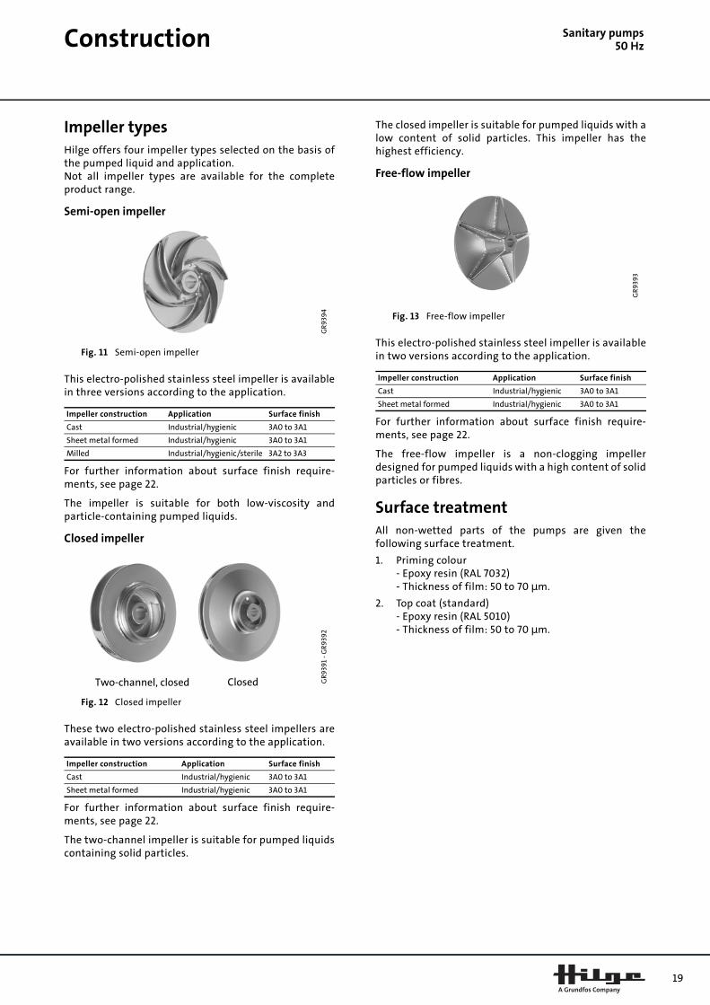
anitary pumps50 HzImpeller typesHilge offers four impeller types selected on the basis ofthe pumped liquid and application.Not all impeller types are available for the completeproduct range.
Semi-open impeller
Fig. 11 Semi-open impeller
This electro-polished stainless steel impeller is availablein three versions according to the application.
For further information about surface finish require-ments, see page 22.
The impeller is suitable for both low-viscosity andparticle-containing pumped liquids.
Closed impeller
Fig. 12 Closed impeller
These two electro-polished stainless steel impellers areavailable in two versions according to the application.
For further information about surface finish require-ments, see page 22.
The two-channel impeller is suitable for pumped liquidscontaining solid particles.
The closed impeller is suitable for pumped liquids with alow content of solid particles. This impeller has thehighest efficiency.
Free-flow impeller
Fig. 13 Free-flow impeller
This electro-polished stainless steel impeller is availablein two versions according to the application.
For further information about surface finish require-ments, see page 22.
The free-flow impeller is a non-clogging impellerdesigned for pumped liquids with a high content of solidparticles or fibres.
Surface treatmentAll non-wetted parts of the pumps are given thefollowing surface treatment.
1. Priming colour- Epoxy resin (RAL 7032)- Thickness of film: 50 to 70 Ìm.
2. Top coat (standard)- Epoxy resin (RAL 5010)- Thickness of film: 50 to 70 Ìm.
GR
939
4
Impeller construction Application Surface finish
Cast Industrial/hygienic 3A0 to 3A1
Sheet metal formed Industrial/hygienic 3A0 to 3A1
Milled Industrial/hygienic/sterile 3A2 to 3A3
GR9
391
- GR
939
2
Impeller construction Application Surface finish
Cast Industrial/hygienic 3A0 to 3A1
Sheet metal formed Industrial/hygienic 3A0 to 3A1
Two-channel, closed Closed
GR9
393
Impeller construction Application Surface finish
Cast Industrial/hygienic 3A0 to 3A1
Sheet metal formed Industrial/hygienic 3A0 to 3A1
19

20
Sanitary pumps50 HzShaft seals
Mechanical shaft sealThe operating range of the shaft seal depends on thetype of shaft seal, operating pressure and liquid temper-ature.
Standard shaft seals are mentioned below; other shaftseals are available on request.
Hygienic applications
As standard Hilge offers a single shaft seal fitted with ametal spring as seal driver for hygienic applications.
Fig. 14 Single seal for hygienic applications.
This shaft seal has seal faces of carbon/stainless steeland O-rings of either EPDM or FKM.
Fig. 15 Operating range of shaft seal with metal spring as seal driver for hygienic applications.
Sterile applications
As standard Hilge offers a closed O-ring seal for sterileapplications.
Fig. 16 Single seal for sterile applications.
The O-ring seal has seal faces of silicon carbide/siliconcarbide (SiC/SiC) and O-rings of EPDM (optionally FFKM(white) or FKM).
Fig. 17 Operating range of closed O-ring seal for sterile applications.
Seals for sanitary pumps
TM0
2 9
66
0 3
60
4TM
03
012
1 41
04
10
5
00 -40 0 20 40 80
p [bar]
-20 60 100t [˚C]
15
21
TM0
2 9
66
4 36
04
TM0
3 0
118
410
4Shaft seal
Pump range
Euro-HYGIA®
Contra SIPLA MAXA MAXANA
Single seal
Tandem
Back-to-back
Standard.
On request.
SiC/
SiC/
EPDM
SiC/SiC/EPDMSiC/SiC/FFKMSiC/SiC/FKM
25
20
15
10
00 -40 0 20 40 80
p [bar]
5
-20 60 100t [˚C]
30

Sanitary pumps50 Hz
CertificationApprovals and certificatesThe design, materials used and surface finish are subjectto a variety of national and international rules and regu-lations. Among these are the 3A sanitary standard, therecommendations of EHEDG (European Hygienic Equip-ment Design Group) and the QHD (Qualified HygienicDesign).
3A sanitary standard
Fig. 18 3A symbol
The 3A sanitary standard provide material specificationsand determination of surface finish.
The goal is to protect consumable products fromcontamination and to ensure that all surfaces can becleaned (CIP).
The 3A symbol is used by manufacturers to indicateconformance to 3A standards.
For further information about surface finish of hygienicpumps, see page 22.
EHEDG (European Hygienic Equipment DesignGroup)
Fig. 19 EHEDG symbol
The EHEDG is a testing system describing the criteria forthe safe and hygienic design of equipment intended forthe processing of food.
The goal is to ensure the microbiological safety of theend product, e.g. the pumped liquid.
The EHEDG symbol is used by manufacturers to indicateconformance to EHEDG recommendations.
QHD (Qualified Hygienic Design)
Fig. 20 QHD symbol
Qualified Hygienic Design (QHD) stands for a two-phasetesting system for the hygienic design and the cleana-bility of components, machinery and plant for aseptic orsterile applications.
The goal is to ensure that all surfaces can be cleaned(CIP).
The QHD symbol is used by manufacturers to indicateconformance to QHD guidelines.
Certificates
General information
Hilge offers a number of certificates and approvals fordifferent purposes. The following types are available:
• Hygienic design certificates(certificates guaranteeing compliance with the 3A sanitary standard, the EHEDG and the QHD recom-mendations)
• material certificates(certificates stating material specifications)
• performance certificates(test reports guaranteeing and certifying test data of QH, current consumption, speed, curves, etc.)
• authorized test by third party(surveyed performance test)
• ATEX-approved sanitary pumps(according to ATEX-directive 94/9/EC)
The certificates must be ordered with the pump.
21
22
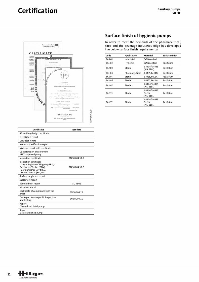
Certification
Sanitary pumps50 HzSurface finish of hygienic pumpsIn order to meet the demands of the pharmaceutical,food and the beverage industries Hilge has developedthe below surface finish requirements:
TM0
3 0
09
1 39
04
Certificate Standard
3A sanitary design certificate
EHEDG test report
QHD test report
Material specification report
Material report with certificate
CE declaration of conformityATEX-approved pump
Inspection certificate EN 10.204 3.1.B
Inspection certificate- Lloyds Register of Shipping (LRS), - Det Norske Veritas (DNV),- Germanischer Lloyd (GL),- Bureau Veritas (BV), etc.
EN 10.204 3.1.C
Surface roughness report
Motor test report
Standard test report ISO 9906
Vibration report
Certificate of compliance with the order
EN 10.204 2.1
Test report - non-specific inspection and testing
EN 10.204 2.2
ReportCleaned and dried pump
ReportElectro-polished pump
Code Application Material Surface finish
3A0.01 Industrial CrNiMo steel
3A1.02 Hygienic CrNiMo steel Ra≤3.2Ìm
3A2.03 Sterile1.4404/1.4435(AISI 316L)
Ra≤0.8Ìm
3A1.04 Pharmaceutical 1.4435, Fe≤3% Ra≤3.2Ìm
3A2.05 Sterile 1.4435, Fe≤1% Ra≤0.8Ìm
3A3.06 Sterile 1.4435, Fe≤1% Ra≤0.4Ìm
3A3.07 Sterile1.4404/1.4435(AISI 316L)
Ra≤0.4Ìm
3A2.33 Sterile1.4404/1.4435Fe≤3%(AISI 316L)
Ra≤0.8Ìm
3A3.37 Sterile1.4404/1.4435Fe≤3%(AISI 316L)
Ra≤0.4Ìm
Sanitary pumps50 Hz
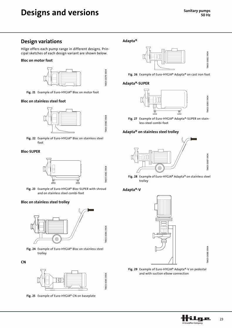
Designs and versionsDesign variationsHilge offers each pump range in different designs. Prin-cipal sketches of each design variant are shown below.
Bloc on motor foot
Fig. 21 Example of Euro-HYGIA® Bloc on motor foot
Bloc on stainless steel foot
Fig. 22 Example of Euro-HYGIA® Bloc on stainless steel foot
Bloc-SUPER
Fig. 23 Example of Euro-HYGIA® Bloc-SUPER with shroud and on stainless steel combi-foot
Bloc on stainless steel trolley
Fig. 24 Example of Euro-HYGIA® Bloc on stainless steel trolley
CN
Fig. 25 Example of Euro-HYGIA® CN on baseplate
Adapta®
Fig. 26 Example of Euro-HYGIA® Adapta® on cast iron foot
Adapta®-SUPER
Fig. 27 Example of Euro-HYGIA® Adapta®-SUPER on stain-less steel combi-foot
Adapta® on stainless steel trolley
Fig. 28 Example of Euro-HYGIA® Adapta® on stainless steel trolley
Adapta®-V
Fig. 29 Example of Euro-HYGIA® Adapta®-V on pedestal and with suction elbow connection
TM0
3 0
079
39
04
TM0
3 0
080
39
04
TM0
3 0
081
39
04
TM0
3 0
086
39
04
TM0
3 0
085
39
04
TM0
3 0
082
39
04
TM0
3 0
083
39
04
TM0
3 0
087
39
04
TM0
3 0
088
39
04
23

24
Designs and versions
Sanitary pumps50 HzThe tables below state possible designs and versions ofeach pump range.
Each version number is described in the version key onpage 26.
Euro-HYGIA® I
Euro-HYGIA® II
Contra I
Contra II
SIPLA 3.1
SIPLA 6.1
SIPLA 12.1
Design Version number
Adapta® ★ 1 2 3 18 19 23 24 31 50 51 52 60 61
Adapta®-
SUPER★★ 1 2 3 18 19 23 31 50 52 60 61
Adapta®-
V★ 8 9 10 11 31 50 51 52 60 61
Bloc 1 2 3 5 6 7 18 19 23 24 50 60 61
Bloc-
SUPER★★ 1 2 3 5 6 7 18 19 23 50 60 61
Bloc-V 8 9 10 11 50 60 61
CN 25 26 27 28 29 30 31 32 33 34 50 51 52 60 61
★ Size I.
★★ SUPER = motor with stainless steel shroud.
Design Version number
Adapta® ★ 1 2 3 18 19 22 23 24 31 50 51 52 60 61
Adapta®-
SUPER★★ 1 2 3 18 19 22 23 31 50 52 60 61
Adapta®-
V★ 8 9 10 11 31 50 51 52 60 61
Bloc 1 2 3 5 6 7 18 19 23 24 50 60 61
Bloc-
SUPER★★ 1 2 3 5 6 7 18 19 23 50 60 61
Bloc-V 8 9 10 11 50 60 61
CN 25 26 27 28 29 30 31 32 33 34 50 51 52 60 61
★ Size II up to frame size 160; frame size 180 is size III.
★★ SUPER = motor with stainless steel shroud.
Design Version number
Adapta® ★ 1 2 3 18 19 23 24 31 50 51 52
Adapta®-
SUPER★★ 1 2 3 18 19 23 31 50 52
Adapta®-V★ 8 9 10 11 31 50 51 52
Bloc 1 2 3 5 6 7 18 19 23 24 50
Bloc-
SUPER★★ 1 2 3 5 6 7 18 19 23 50
Bloc-V 8 9 10 11 50
CN 25 26 27 28 29 30 31 32 33 34 50 51 52
★ Size I.
★★ SUPER = motor with stainless steel shroud.
Design Version number
Adapta® ★ 1 2 3 18 19 22 23 24 31 50 51 52
Adapta®-
SUPER★★ 1 2 3 18 19 22 23 31 50 52
Adapta®-V★ 8 9 10 11 31 50 51 52
Bloc 1 2 3 5 6 7 18 19 23 24 50
Bloc-
SUPER★★ 1 2 3 5 6 7 18 19 23 50
Bloc-V 8 9 10 11 50
CN 25 26 27 28 29 30 31 32 33 34 35 50 51 52
★ Size II up to frame size 160; frame size 180 is size III.
★★ SUPER = motor with stainless steel shroud.
Design Version number
Adapta® ★ 1 2 3 18 19 23 31 51 52 53
Adapta®-
SUPER★★ 1 2 3 18 19 23 31 52 53
Bloc 4 5 18 19 32 33 51 54
Bloc-
SUPER★★ 4 18
CN 25 26 27 28 30 31 32 33 34 51 52
★ Size I.
★★ SUPER = motor with stainless steel shroud.
Design Version number
Adapta® ★ 1 2 3 18 19 23 31 50 51 52 53
Adapta®-
SUPER★★ 1 2 3 18 19 23 31 50 52 53
Bloc 4 5 18 19 32 33 50 51 54
Bloc-
SUPER★★ 4 18 50
CN 25 26 27 28 30 31 32 33 34 50 51 52
★ Size I.
★★ SUPER = motor with stainless steel shroud.
Design Version number
Adapta® ★ 1 2 3 18 19 23 31 50 51 52 53
Adapta®-
SUPER★★ 1 2 3 18 19 23 31 50 52 53
Bloc 4 5 18 19 32 33 50 51 54
Bloc-
SUPER★★ 4 18 50
CN 25 26 27 28 30 31 32 33 34 50 51 52
★ Size I.
★★ SUPER = motor with stainless steel shroud.

Designs and versions S
anitary pumps50 HzSIPLA 18.1
SIPLA 28.1
SIPLA 52.1
SIPLA 65.1
SIPLA 90.1
MAXA
MAXANA
Design Version number
Adapta® ★ 1 2 3 18 19 23 31 50 51 52 53
Adapta®-
SUPER★★ 1 2 3 18 19 23 31 50 52 53
Bloc 4 5 18 19 32 33 50 51 54
Bloc-
SUPER★★ 4 18 50
CN 25 26 27 28 30 31 32 33 34 50 51 52
★ Size II.
★★ SUPER = motor with stainless steel shroud.
Design Version number
Adapta® ★ 1 2 3 18 19 23 31 50 51 52 53
Adapta®-
SUPER★★ 1 2 3 18 19 23 31 50 52 53
Bloc 4 5 18 19 32 33 50 51 54
Bloc-
SUPER★★ 4 18 50
CN 25 26 27 28 30 31 32 33 34 50 51 52
★ Size II.
★★ SUPER = motor with stainless steel shroud.
Design Version number
Adapta® ★ 1 2 3 18 19 23 31 50 51 52 53
Adapta®-
SUPER★★ 1 2 3 18 19 23 31 50 52 53
Bloc 4 5 18 19 50 54
Bloc-
SUPER★★ 4 18 50 54
CN 25 26 27 28 30 31 32 33 34 50 51 52
★ Size II.
★★ SUPER = motor with stainless steel shroud.
Design Version number
Adapta® ★ 22 31 51 52 53
Adapta®-
SUPER★★ 4 22 31 52
Bloc 4 5
Bloc-
SUPER★★ 4
CN 25 26 27 28 30 31 32 33 34 51 52
★ Size III.
★★ SUPER = motor with stainless steel shroud.
Design Version number
Adapta® ★ 22 31 51 52 53
Adapta®-
SUPER★★ 4 22 31 52
Bloc 4 5
Bloc-
SUPER★★ 4
CN 25 26 27 28 30 31 32 33 34 51 52
★ Size III.
★★ SUPER = motor with stainless steel shroud.
Design Version number
Adapta® ★ 1 2 22 31 50 51 52
Adapta® ★★ 22 31 51 52
Adapta®-V★ 8 10 31 50 51 52
Adapta®-
V★★ 16 31 51 52
L 5 6 7 21 31 50 51 52
C★★★ 25 26 27 28 29 30 31 32 33 34 50 51 52
CN★★★★ 25 26 27 28 29 30 31 32 33 34 50 51 52
★ Size II.
★★ Size III.
★★★ CN with shaft sleeve.
★★★★ N.
Design Version number
Adapta® ★ 1 2 22 31 50 51 52
Adapta® ★★ 22 31 51 52
Adapta®-
SUPER★★★ 8 10 31 50 51 52
Bloc 16 31 51 52
L 5 6 7 21 31 50 51 52
C★★★★ 25 26 27 28 29 30 31 32 33 34 50 51 52
CN ★★★★★ 25 26 27 28 29 30 31 32 33 34 50 51 52
★ Size II.
★★ Size III.
★★★ SUPER = motor with stainless steel shroud.
★★★★ CN with shat sleeve.
★★★★★ N.
25
26
Designs and versions
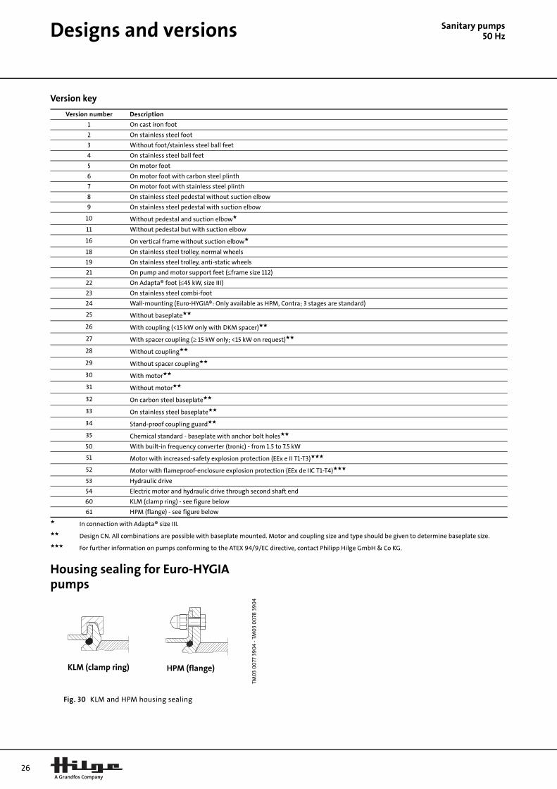
Sanitary pumps50 HzVersion key
Housing sealing for Euro-HYGIA pumps
Fig. 30 KLM and HPM housing sealing
Version number Description
1 On cast iron foot
2 On stainless steel foot
3 Without foot/stainless steel ball feet
4 On stainless steel ball feet
5 On motor foot
6 On motor foot with carbon steel plinth
7 On motor foot with stainless steel plinth
8 On stainless steel pedestal without suction elbow
9 On stainless steel pedestal with suction elbow
10 Without pedestal and suction elbow★
11 Without pedestal but with suction elbow
16 On vertical frame without suction elbow★
18 On stainless steel trolley, normal wheels
19 On stainless steel trolley, anti-static wheels
21 On pump and motor support feet (≤frame size 112)
22 On Adapta® foot (≤45 kW, size III)
23 On stainless steel combi-foot
24 Wall-mounting (Euro-HYGIA®: Only available as HPM, Contra; 3 stages are standard)
25 Without baseplate★★
26 With coupling (<15 kW only with DKM spacer)★★
27 With spacer coupling (≥ 15 kW only; <15 kW on request)★★
28 Without coupling★★
29 Without spacer coupling★★
30 With motor★★
31 Without motor★★
32 On carbon steel baseplate★★
33 On stainless steel baseplate★★
34 Stand-proof coupling guard★★
35 Chemical standard - baseplate with anchor bolt holes★★
50 With built-in frequency converter (tronic) - from 1.5 to 7.5 kW
51 Motor with increased-safety explosion protection (EEx e II T1-T3)★★★
52 Motor with flameproof-enclosure explosion protection (EEx de IIC T1-T4)★★★
53 Hydraulic drive
54 Electric motor and hydraulic drive through second shaft end
60 KLM (clamp ring) - see figure below
61 HPM (flange) - see figure below
★ In connection with Adapta® size III.
★★ Design CN. All combinations are possible with baseplate mounted. Motor and coupling size and type should be given to determine baseplate size.
★★★ For further information on pumps conforming to the ATEX 94/9/EC directive, contact Philipp Hilge GmbH & Co KG.
TM0
3 0
077
39
04
- TM
03
00
78 3
90
4
KLM (clamp ring) HPM (flange)

Sanitary pumps50 Hzns
Standard pipe connectioEuro-HYGIA® I
ConnectionsDIN 32/25 32/32 40/25 40/32 40/40 50/32 50/40 50/50 65/40 65/50
OD 1 1/4 / 1 1 1/4 / 1 1/4 1 ½ / 1 1 ½ / 1 1/4 1 ½ / 1 ½ 2 / 1 1/4 2 / 1 ½ 2 / 2 2 ½ / 1 ½ 2 ½ / 2
ThreadedconnectionDIN 11851(3A0-3A1)
a1 75 75 75 75 75 75 75 75 75 75
e1 85 85 85 85 85 85 85 75 85 75
h2 170 170 170 170 170 170 170 170 170 170
e5 109 109 120 120 120 135 135 135 145 145
h3 132 132 133 133 133 148 148 148 160 160
Asepticthreadedconnection
DIN 11864-1★
(3A0-3A3)
a1 86 86 82 82 82 78 78 78 78 78
e1 85 85 85 85 85 85 85 75 85 75
h2 183 187 183 187 188 187 188 188 188 188
e5 105 105 108 108 108 136 136 136 146 146
h3 120 120 131 131 131 144 144 144 156 156
Asepticflange
DIN 11864-2★★
(3A0-3A3)
a1 81 81 76 76 76 72 72 72 67 67
e1 85 85 85 85 85 85 85 75 85 75
h2 182 182 182 182 182 182 182 182 182 182
e5 112 112 122 122 122 135 135 135 142 142
h3 115 115 125 125 125 138 138 138 145 145
Clamp toDIN 32676(3A0-3A2)
a1 87 87 77 77 77 73 73 73 75 75
e1 85 85 85 85 85 85 85 75 85 75
h2 178 178 178 178 170 178 170 178 170 178
e5 113 113 123 123 123 136 136 136 150 150
h3 111 111 121 121 121 134 134 134 148 148
Flange
DIN EN 1092-1★★★
(DIN 2633/42)PN 10(3A0)
a1 75 75 75 75 75 75 75 75 75 75
e1 85 85 85 85 85 85 85 75 85 75
h2 170 170 170 170 170 170 170 170 170 170
e5 105 105 115 115 115 128 128 128 145 145
h3 103 103 113 113 113 126 126 126 143 143
Clamp toTri-CloverITE-Tri-Clamp(3A0-3A2)
a1 - - 88 - 88 - 86 86 70 70
e1 - - 85 - 85 - 85 75 85 75
h2 - - 185 - 185 - 185 185 185 185
e5 - - 123 - 123 -On request
h3 - - 121 - 121 -
Weld neckflangeDIN EN 1092-1(DIN 2633)PN 16(3A0)
a1 100(10) 100(10) 100 100 100 97 97 97 97 97
e1 85 85 85 85 85 85 85 75 85 75
h2 170 197 170 197 199 197 199 202 199 202
e5On request
h3
ThreadedconnectionDIN ISO 228(male)(3A0)
a1 85 85 81 81 81 80 80 80 - -
e1 85 85 85 85 85 85 85 75 - -
h2 170 170 170 170 170 170 170 170 - -
e5On request
- -
h3 - -
Tolerances to DIN EN 735 connection dimensions for centrifugal pumps.
★ Aseptic threaded connection for pipes to DIN 11850 row 2/3, Form A.
★★ Aseptic grooved flange for pipes to DIN 11850 row 2/3, Form A.
★★★ DNs/DNd - fixed/loose flange (DNs 65 as DIN 2642-loose flange).
(10) Dimensions for KLM version. For HPM version dimension a1 is 91mm for DNs 32.
Dimensions e5 and h3 for vertical version. Discharge branch cannot be completely drained (not eccentric).
27

28
Pipe connections
Sanitary pumps50 HzEuro-HYGIA® II
ConnectionsDIN 50/50 65/50 65/65 80/50 80/65 80/80 100/65 100/80 100/100 125/80 125/100
OD 2 / 2 2 ½ / 2 2½ / 2½ 3 / 2 3 / 2½ 3 / 3 4 / 2½ 4 / 3 4 / 4 5 / 3 5 / 4
ThreadedconnectionDIN 11851(3A0-3A1)
a1 116 116 116 116 116 116 116 116 116 116 116
e1 98 98 98 98 98 85.5 98 85.5 85.5 85.5 85.5
h2 200 200 200 200 200 200 200 200 200 200 200
e5 135 145 145 175 175 175 190 190 190 - -
h3 148 160 160 190 190 190 209 209 209 - -
Asepticthreadedconnection
DIN 11864-1★
(3A0-3A3)
a1 112 119 119 125 125 125 133 133 133 - -
e1 98 98 98 98 98 85.5 98 85.5 85.5 - -
h2 206 206 213 206 213 220 213 220 227 - -
e5 136 146 146 175 175 175 191 191 191 - -
h3 144 156 156 187 187 187 205 205 205 - -
Asepticflange
DIN 11864-2★★
(3A0-3A3)
a1 106.5 108.5 108.5 110.5 110.5 110.5 110.5 110.5 110.5 - -
e1 98 98 98 98 98 85.5 98 85.5 85.5 - -
h2 200.5 200.5 202.5 200.5 202.5 205.5 202.5 205.5 204.5 - -
e5 135.5 142.5 142.5 169.5 169.5 169.5 179.5 179.5 179.5 - -
h3 138.5 145.5 145.5 172.5 172.5 172.5 182.5 182.5 182.5 - -
Clamp toDIN 32676(3A0-3A2)
a1 102.5 111 111 111 111 111 111 111 111 - -
e1 98 98 98 98 98 85.5 98 85.5 85.5 - -
h2 209 209 228 209 228 206 228 206 205 - -
e5 136.5 150 150 175 175 175 185 185 185 - -
h3 134.5 148 148 173 173 173 183 183 183 - -
Flange
DIN EN 1092-1★★★
(DIN 2633/42)PN 10(3A0)
a1 116 116 116 116 116 116 116 116 116 116 116
e1 98 98 98 98 98 85.5 98 85.5 85.5 85.5 85.5
h2 200 200 200 200 200 200 200 200 200 200 200
e5 128 145 145 170 170 170 185 185 185 - -
h3 126 143 143 168 168 168 183 183 183 - -
Clamp toTri-CloverITE-Tri-Clamp(3A0-3A2)
a1 109.6 109.6 109.6 111.6 111.6 111.6 111.6 111.6 111.6 - -
e1 98 98 98 98 98 98 98 98 85.5 - -
h2 215.6 215.6 215.6 215.6 215.6 225 215.6 225 215.6 - -
e5On request
- -
h3 - -
Weld neckflangeDIN EN 1092-1(DIN 2633)PN 16(3A0)
a1 126 128 128 133 133 133 135 135 135 - -
e1 98 98 98 98 98 85.5 98 85.5 85.5 - -
h2 232 232 234 232 234 228 234 228 229 - -
e5On request
- -
h3 - -
FlangeAPV FN1/FG1PN 10(3A0-3A1)
a1 105 107 107 107 107 107 107 107 107 145 145
e1 98 98 98 98 98 85.5 98 85.5 85.5 85.5 85.5
h2 199 199 224 199 224 200 224 200 200 200 200
e5On request
- -
h3 - -
Tolerances to DIN EN 735 connection dimensions for centrifugal pumps.
★ Aseptic threaded connection for pipes to DIN 11850 row 2/3, Form A.
★★ Aseptic grooved flange for pipes to DIN 11850 row 2/3, Form A.
★★★DNs/DNd - fixed/loose flange (DNs 1255 as DIN 2642-loose flange. Attention! This type of connection cannot be used for Bloc-SUPER with frame size 160. Use weld neck flange to DIN 2633.
Dimensions e5 and h3 for vertical version. Discharge branch cannot be completely drained (not eccentric).
Pipe connections S
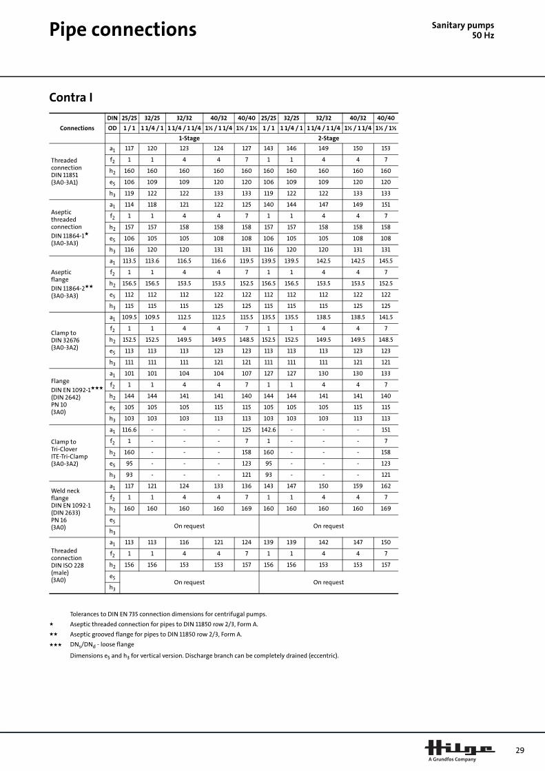
anitary pumps50 HzContra I
Connections
DIN 25/25 32/25 32/32 40/32 40/40 25/25 32/25 32/32 40/32 40/40
OD 1 / 1 1 1/4 / 1 1 1/4 / 1 1/4 1½ / 1 1/4 1½ / 1½ 1 / 1 1 1/4 / 1 1 1/4 / 1 1/4 1½ / 1 1/4 1½ / 1½
1-Stage 2-Stage
ThreadedconnectionDIN 11851(3A0-3A1)
a1 117 120 123 124 127 143 146 149 150 153
f2 1 1 4 4 7 1 1 4 4 7
h2 160 160 160 160 160 160 160 160 160 160
e5 106 109 109 120 120 106 109 109 120 120
h3 119 122 122 133 133 119 122 122 133 133
Asepticthreadedconnection
DIN 11864-1★
(3A0-3A3)
a1 114 118 121 122 125 140 144 147 149 151
f2 1 1 4 4 7 1 1 4 4 7
h2 157 157 158 158 158 157 157 158 158 158
e5 106 105 105 108 108 106 105 105 108 108
h3 116 120 120 131 131 116 120 120 131 131
Asepticflange
DIN 11864-2★★
(3A0-3A3)
a1 113.5 113.6 116.5 116.6 119.5 139.5 139.5 142.5 142.5 145.5
f2 1 1 4 4 7 1 1 4 4 7
h2 156.5 156.5 153.5 153.5 152.5 156.5 156.5 153.5 153.5 152.5
e5 112 112 112 122 122 112 112 112 122 122
h3 115 115 115 125 125 115 115 115 125 125
Clamp toDIN 32676(3A0-3A2)
a1 109.5 109.5 112.5 112.5 115.5 135.5 135.5 138.5 138.5 141.5
f2 1 1 4 4 7 1 1 4 4 7
h2 152.5 152.5 149.5 149.5 148.5 152.5 152.5 149.5 149.5 148.5
e5 113 113 113 123 123 113 113 113 123 123
h3 111 111 111 121 121 111 111 111 121 121
Flange
DIN EN 1092-1★★★
(DIN 2642)PN 10(3A0)
a1 101 101 104 104 107 127 127 130 130 133
f2 1 1 4 4 7 1 1 4 4 7
h2 144 144 141 141 140 144 144 141 141 140
e5 105 105 105 115 115 105 105 105 115 115
h3 103 103 103 113 113 103 103 103 113 113
Clamp toTri-CloverITE-Tri-Clamp(3A0-3A2)
a1 116.6 - - - 125 142.6 - - - 151
f2 1 - - - 7 1 - - - 7
h2 160 - - - 158 160 - - - 158
e5 95 - - - 123 95 - - - 123
h3 93 - - - 121 93 - - - 121
Weld neckflangeDIN EN 1092-1(DIN 2633)PN 16(3A0)
a1 117 121 124 133 136 143 147 150 159 162
f2 1 1 4 4 7 1 1 4 4 7
h2 160 160 160 160 169 160 160 160 160 169
e5On request On request
h3
ThreadedconnectionDIN ISO 228(male)(3A0)
a1 113 113 116 121 124 139 139 142 147 150
f2 1 1 4 4 7 1 1 4 4 7
h2 156 156 153 153 157 156 156 153 153 157
e5On request On request
h3
Tolerances to DIN EN 735 connection dimensions for centrifugal pumps.
★ Aseptic threaded connection for pipes to DIN 11850 row 2/3, Form A.
★★ Aseptic grooved flange for pipes to DIN 11850 row 2/3, Form A.
★★★ DNs/DNd - loose flange
Dimensions e5 and h3 for vertical version. Discharge branch can be completely drained (eccentric).
29
30
Pipe connections
Sanitary pumps50 HzConnections
DIN 25/25 32/25 32/32 40/32 40/40 25/25 32/25 32/32 40/32 40/40
OD 1 / 1 1 1/4 / 1 1 1/4 / 1 1/4 1½ / 1 1/4 1½ / 1½ 1 / 1 1 1/4 / 1 1 1/4 / 1 1/4 1½ / 1 1/4 1½ / 1½
3-Stage 4-Stage
ThreadedconnectionDIN 11851(3A0-3A1)
a1 169 172 175 176 179 195 198 201 202 205
f2 1 1 4 4 7 1 1 4 4 7
h2 160 160 160 160 160 160 160 160 160 160
e5 106 109 109 120 120 106 109 109 120 120
h3 119 122 122 133 133 119 122 122 133 133
Asepticthreadedconnection
DIN 11864-1★
(3A0-3A3)
a1 166 170 173 174 177 192 196 199 201 203
f2 1 1 4 4 7 1 1 4 4 7
h2 157 157 158 158 158 157 157 158 158 158
e5 106 105 105 108 108 106 105 105 108 108
h3 116 120 120 131 131 116 120 120 131 131
Asepticflange
DIN 11864-2★★
(3A0-3A3)
a1 165.5 165.5 168.5 168.5 171.5 191.5 191.5 194.5 194.5 197.5
f2 1 1 4 4 7 1 1 4 4 7
h2 156.5 156.5 153.5 153.5 152.5 156.5 156.5 153.5 153.5 152.5
e5 112 112 112 122 122 112 112 112 122 122
h3 115 115 115 125 125 115 115 115 125 125
Clamp toDIN 32676(3A0-3A2)
a1 161.5 161.5 164.5 164.5 167.5 187.5 187.5 190.5 190.5 193.5
f2 1 1 4 4 7 1 1 4 4 7
h2 152.5 152.5 149.5 149.5 148.5 152.5 152.5 149.5 149.5 148.5
e5 113 113 113 123 123 113 113 113 123 123
h3 111 111 111 121 121 111 111 111 121 121
Flange
DIN EN 1092-1★★★
(DIN 2642)PN 10(3A0)
a1 153 153 156 156 159 179 179 182 182 185
f2 1 1 4 4 7 1 1 4 4 7
h2 144 144 141 141 140 144 144 141 141 140
e5 105 105 105 115 115 105 105 105 115 115
h3 103 103 103 113 113 103 103 103 113 113
Clamp toTri-CloverITE-Tri-Clamp(3A0-3A2)
a1 168.6 - - - 177 194.6 - - - 203
f2 1 - - - 7 1 - - - 7
h2 160 - - - 158 160 - - - 158
e5 95 - - - 123 95 - - - 123
h3 93 - - - 121 93 - - - 121
Weld neckflangeDIN EN 1092-1(DIN 2633)PN 16(3A0)
a1 169 173 176 185 188 195 199 202 211 214
f2 1 1 4 4 7 1 1 4 4 7
h2 160 160 160 160 169 160 160 160 160 169
e5On request On request
h3
ThreadedconnectionDIN ISO 228(male)(3A0)
a1 165 165 168 173 176 191 191 194 199 202
f2 1 1 4 4 7 1 1 4 4 7
h2 156 156 153 153 157 156 156 153 153 157
e5On request On request
h3
Tolerances to DIN EN 735 connection dimensions for centrifugal pumps.
★ Aseptic threaded connection for pipes to DIN 11850 row 2/3, Form A.
★★ Aseptic grooved flange for pipes to DIN 11850 row 2/3, Form A.
★★★ DNs/DNd - loose flange
Dimensions e5 and h3 for vertical version. Discharge branch can be completely drained (eccentric).
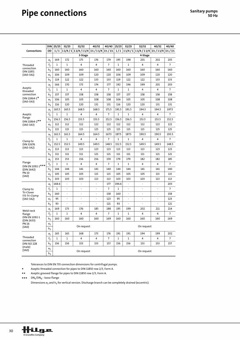
Pipe connections S
anitary pumps50 HzConnections
DIN 25/25 32/25 32/32 40/32 40/40 25/25 32/25 32/32 40/32 40/40
OD 1 / 1 1 1/4 / 1 1 1/4 / 1 1/4 1½ / 1 1/4 1½ / 1½ 1 / 1 1 1/4 / 1 1 1/4 / 1 1/4 1½ / 1 1/4 1½ / 1½
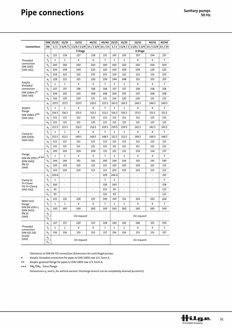
5-Stage 6-Stage
ThreadedconnectionDIN 11851(3A0-3A1)
a1 221 224 227 228 231 247 250 253 254 257
f2 1 1 4 4 7 1 1 4 4 7
h2 160 160 160 160 160 160 160 160 160 160
e5 106 109 109 120 120 106 109 109 120 120
h3 119 122 122 133 133 119 122 122 133 133
Asepticthreadedconnection
DIN 11864-1★
(3A0-3A3)
a1 218 222 225 226 229 244 248 251 253 255
f2 1 1 4 4 7 1 1 4 4 7
h2 157 157 158 158 158 157 157 158 158 158
e5 106 105 105 108 108 106 105 105 108 108
h3 116 120 120 131 131 116 120 120 131 131
Asepticflange
DIN 11864-2★★
(3A0-3A3)
a1 217.5 217.5 220.5 220.5 223.5 243.5 243.5 246.5 246.5 249.5
f2 1 1 4 4 7 1 1 4 4 7
h2 156.5 156.5 153.5 153.5 152.5 156.5 156.5 153.5 153.5 152.5
e5 112 112 112 122 122 112 112 112 122 122
h3 115 115 115 125 125 115 115 115 125 125
Clamp toDIN 32676(3A0-3A2)
a1 213.5 213.5 216.5 216.5 219.5 239.5 239.5 242.5 242.5 245.5
f2 1 1 4 4 7 1 1 4 4 7
h2 152.5 152.5 149.5 149.5 148.5 152.5 152.5 149.5 149.5 148.5
e5 113 113 113 123 123 113 113 113 123 123
h3 111 111 111 121 121 111 111 111 121 121
Flange
DIN EN 1092-1★★★
(DIN 2642)PN 10(3A0)
a1 205 205 209 209 211 231 231 234 234 237
f2 1 1 4 4 7 1 1 4 4 7
h2 144 144 141 141 140 144 144 141 141 140
e5 105 105 105 115 115 105 105 105 115 115
h3 103 103 103 113 113 103 103 103 113 113
Clamp toTri-CloverITE-Tri-Clamp(3A0-3A2)
a1 220.6 - - - 229 246.6 - - - 255
f2 1 - - - 7 1 - - - 7
h2 160 - - - 158 160 - - - 158
e5 95 - - - 123 95 - - - 123
h3 93 - - - 121 93 - - - 121
Weld neckflangeDIN EN 1092-1(DIN 2633)PN 16(3A0)
a1 221 225 228 237 240 247 251 254 263 266
f2 1 1 4 4 7 1 1 4 4 7
h2 160 160 160 160 169 160 160 160 160 169
e5On request On request
h3
ThreadedconnectionDIN ISO 228(male)(3A0)
a1 217 217 220 225 228 243 243 246 251 254
f2 1 1 4 4 7 1 1 4 4 7
h2 156 156 153 153 157 156 156 153 153 157
e5On request On request
h3
Tolerances to DIN EN 735 connection dimensions for centrifugal pumps.
★ Aseptic threaded connection for pipes to DIN 11850 row 2/3, Form A.
★★ Aseptic grooved flange for pipes to DIN 11850 row 2/3, Form A.
★★★ DNs/DNd - loose flange
Dimensions e5 and h3 for vertical version. Discharge branch can be completely drained (eccentric).
31

32
Pipe connections
Sanitary pumps50 HzContra II
Connections
DIN 50/40 50/50 65/50 65/65 80/65 50/40 50/50 65/50 65/65 80/65
OD 2 / 1½ 2 / 2 2½ / 2 2½ / 2½ 3 / 2½ 2 / 1½ 2 / 2 2½ / 2 2½ / 2½ 3 / 2½
1-Stage 2-Stage
ThreadedconnectionDIN 11851(3A0-3A1)
a1 124 127 132 140 145 156 159 164 172 177
f2 0 3 3 11 11 0 3 3 11 11
h2 205 205 205 205 205 205 205 205 205 205
e5 135 135 145 145 175 135 135 145 145 175
h3 148 148 160 160 190 148 148 160 160 190
Asepticthreadedconnection
DIN 11864-1★
(3A0-3A3)
a1 120 123 128 136 142 152 155 160 168 174
f2 0 3 3 11 11 0 3 3 11 11
h2 203 201 201 201 201 203 201 201 201 201
e5 136 136 146 146 175 136 136 146 146 175
h3 144 144 156 156 187 144 144 156 156 187
Asepticflange
DIN 11864-2★★
(3A0-3A3)
a1 113 116 117 125 127 145 148 149 157 159
f2 0 3 3 11 11 0 3 3 11 11
h2 198 196 196 191 191 198 196 196 191 191
e5 135.5 135.5 142.5 142.5 169.5 135.5 135.5 142.5 142.5 169.5
h3 138.5 138.5 145.5 145.5 172.5 138.5 138.5 145.5 14.5 172.5
Clamp toDIN 32676(3A0-3A2)
a1 110 113 120 128 128 142 145 152 160 160
f2 0 3 3 11 11 0 3 3 11 11
h2 194 192 192 193 193 194 192 192 193 193
e5 136.5 136.5 150 150 175 136.5 136.5 150 150 175
h3 134.5 134.5 148 148 173 134.5 134.5 148 148 173
Flange
DIN EN 1092-1★★★
(DIN 2642)PN 10(3A0)
a1 102 105 115 123 122 134 137 147 155 154
f2 0 3 3 11 11 0 3 3 11 11
h2 185 183 183 188 188 185 183 183 188 188
e5 128 128 145 145 170 128 128 145 145 170
h3 126 126 143 143 168 126 126 143 143 168
Clamp toTri-CloverITE-Tri-Clamp(3A0-3A2)
a1 146 149 - - - 178 181 - - -
f2 0 3 3 11 11 0 3 3 11 11
h2 201 199 199 194 194 201 199 199 194 194
e5On request On request
h3
Weld neckflangeDIN EN 1092-1(DIN 2633)PN 16(3A0)
a1 134 137 137 145 - 166 169 169 177 -
f2 0 3 3 11 - 0 3 3 11 -
h2 214 215 215 210 - 214 215 215 210 -
e5On request On request
h3
AVP-FG1ThreadedconnectionDIN ISO 228(male)(3A0)
a1 113 116 116 124 - 145 148 148 156 -
f2 0 3 3 11 - 0 3 3 11 -
h2 - 194 194 189 - - 194 194 189 -
e5On request On request
h3
Tolerances to DIN EN 735 connection dimensions for centrifugal pumps.
★ Aseptic threaded connection for pipes to DIN 11850 row 2/3, Form A.
★★ Aseptic grooved flange for pipes to DIN 11850 row 2/3, Form A.
★★★ DNs/DNd - loose flange
Dimensions e5 and h3 for vertical version. Discharge branch can be completely drained (eccentric).

Pipe connections S
anitary pumps50 HzConnections
DIN 50/40 50/50 65/50 65/65 80/65 50/40 50/50 65/50 65/65 80/65
OD 2 / 1½ 2 / 2 2½ / 2 2½ / 2½ 3 / 2½ 2 / 1½ 2 / 2 2½ / 2 2½ / 2½ 3 / 2½
3-Stage 4-Stage
ThreadedconnectionDIN 11851(3A0-3A1)
a1 188 191 196 204 209 220 223 228 236 241
f2 0 3 3 11 11 0 3 3 11 11
h2 205 205 205 205 205 205 205 205 205 205
e5 135 135 145 145 175 135 135 145 145 175
h3 148 148 160 160 190 148 148 160 160 190
Asepticthreadedconnection
DIN 11864-1★
(3A0-3A3)
a1 184 187 192 200 206 216 219 224 232 238
f2 0 3 3 11 11 0 3 3 11 11
h2 203 201 201 201 201 203 201 201 201 201
e5 136 136 146 146 175 136 136 146 146 175
h3 144 144 156 156 187 144 144 156 156 187
Asepticflange
DIN 11864-2★★
(3A0-3A3)
a1 177 180 181 189 191 209 212 213 221 223
f2 0 3 3 11 11 0 3 3 11 11
h2 198 196 196 191 191 198 196 196 191 191
e5 135.5 135.5 142.5 142.5 169.5 135.5 135.5 142.5 142.5 169.5
h3 138.5 138.5 145.5 14.5 172.5 138.5 138.5 145.5 14.5 172.5
Clamp toDIN 32676(3A0-3A2)
a1 174 177 184 192 192 206 209 216 224 224
f2 0 3 3 11 11 0 3 3 11 11
h2 194 192 192 193 193 194 192 192 193 193
e5 136.5 136.5 150 150 175 136.5 136.5 150 150 175
h3 134.5 134.5 148 148 173 134.5 134.5 148 148 173
Flange
DIN EN 1092-1★★★
(DIN 2642)PN 10(3A0)
a1 166 169 179 187 186 198 201 211 219 218
f2 0 3 3 11 11 0 3 3 11 11
h2 185 183 183 188 188 185 183 183 188 188
e5 128 128 145 145 170 128 128 145 145 170
h3 126 126 143 143 168 126 126 143 143 168
Clamp toTri-CloverITE-Tri-Clamp(3A0-3A2)
a1 210 213 - - - 242 245 - - -
f2 0 3 3 11 11 0 3 3 11 11
h2 201 199 199 194 194 201 199 199 194 194
e5On request On request
h3
Weld neckflangeDIN EN 1092-1(DIN 2633)PN 16(3A0)
a1 198 201 201 209 - 230 233 233 241 -
f2 0 3 3 11 - 0 3 3 11 -
h2 214 215 215 210 - 214 215 215 210 -
e5On request On request
h3
AVP-FG1ThreadedconnectionDIN ISO 228(male)(3A0)
a1 177 180 180 188 - 209 212 212 220 -
f2 0 3 3 11 - 0 3 3 11 -
h2 - 194 194 189 - - 194 194 189 -
e5On request On request
h3
Tolerances to DIN EN 735 connection dimensions for centrifugal pumps.
★ Aseptic threaded connection for pipes to DIN 11850 row 2/3, Form A.
★★ Aseptic grooved flange for pipes to DIN 11850 row 2/3, Form A.
★★★ DNs/DNd - loose flange
Dimensions e5 and h3 for vertical version. Discharge branch can be completely drained (eccentric).
33

34
Pipe connections
Sanitary pumps50 HzConnections
DIN 50/40 50/50 65/50 65/65 80/65
OD 2 / 1½ 2 / 2 2½ / 2 2½ / 2½ 3 / 2½
5-Stage
ThreadedconnectionDIN 11851(3A0-3A1)
a1 252 255 260 268 273
f2 0 3 3 11 11
h2 205 205 205 205 205
e5 135 135 145 145 175
h3 148 148 160 160 190
Asepticthreadedconnection
DIN 11864-1★
(3A0-3A3)
a1 248 251 256 264 270
f2 0 3 3 11 11
h2 203 201 201 201 201
e5 136 136 146 146 175
h3 144 144 156 156 187
Asepticflange
DIN 11864-2★★
(3A0-3A3)
a1 241 244 245 253 255
f2 0 3 3 11 11
h2 198 196 196 191 191
e5 135.5 135.5 142.5 142.5 169.5
h3 138.5 138.5 145.5 14.5 172.5
Clamp toDIN 32676(3A0-3A2)
a1 238 241 248 256 256
f2 0 3 3 11 11
h2 194 192 192 193 193
e5 136.5 136.5 150 150 175
h3 134.5 134.5 148 148 173
Flange
DIN EN 1092-1★★★
(DIN 2642)PN 10(3A0)
a1 230 233 243 251 250
f2 0 3 3 11 11
h2 185 183 183 188 188
e5 128 128 145 145 170
h3 126 126 143 143 168
Clamp toTri-CloverITE-Tri-Clamp(3A0-3A2)
a1 274 277 - - -
f2 0 3 3 11 11
h2 201 199 199 194 194
e5On request
h3
Weld neckflangeDIN EN 1092-1(DIN 2633)PN 16(3A0)
a1 262 265 265 273 -
f2 0 3 3 11 -
h2 214 215 215 210 -
e5On request
h3
AVP-FG1ThreadedconnectionDIN ISO 228(male)(3A0)
a1 241 244 244 252 -
f2 0 3 3 11 -
h2 - 194 194 189 -
e5On request
h3
Tolerances to DIN EN 735 connection dimensions for centrifugal pumps.
★ Aseptic threaded connection for pipes to DIN 11850 row 2/3, Form A.
★★ Aseptic grooved flange for pipes to DIN 11850 row 2/3, Form A.
★★★ DNs/DNd - loose flange
Dimensions e5 and h3 for vertical version. Discharge branch can be completely drained (eccentric).

Pipe connections S
anitary pumps50 HzMAXA
MAXA, frame size 80-160
MAXA, frame size 80-200
MAXA, frame size 80-250
MAXA, frame size 80-315
MAXA, frame size 100-200
MAXA, frame size 100-250
MAXA, frame size 125-250
MAXA, frame size 100-315
MAXA, frame size 125-315
MAXA, frame size 150-250
MAXA, frame size 150-315
MAXA, frame size 150-400
MAXA, frame size 200-400
ConnectionsDIN 100/80 125/80 125/100 150/80
OD 4 / 3 5 / 3 5 / 4 6 / 3
Kremo-flangeDIN EN 1092-1(DIN 2633)(3A0)
a1 125 125 - 125
h2 225 225 - 225
ConnectionsDIN 100/80 100/100 125/80 125/100 150/80 150/100
OD 4 / 3 4 / 4 5 / 3 5 / 4 6 / 3 6 / 4
Kremo-flangeDIN EN 1092-1(DIN 2633)(3A0)
a1 125 125 - - - 125
h2 250 250 - - - 250
ConnectionsDIN 100/80 100/100 125/80 125/100 150/80 150/100
OD 4 / 3 4 / 4 5 / 3 5 / 4 6 / 3 6 / 4
Kremo-flangeDIN EN 1092-1(DIN 2633)(3A0)
a1 125 - - 125 125 125
h2 280 - - 280 280 280
ConnectionsDIN 100/80 100/100 125/80 125/100 150/80 150/100
OD 4 / 3 4 / 4 5 / 3 5 / 4 6 / 3 6 / 4
Kremo-flangeDIN EN 1092-1(DIN 2633)(3A0)
a1 125 125 125 125 125 125
h2 315 315 315 315 315 315
ConnectionsDIN 125/100 125/125 150/100 150/125
OD 5 / 4 5 / 5 6 / 4 6 / 5
Kremo-flangeDIN EN 1092-1(DIN 2633)(3A0)
a1 125 125 125 125
h2 280 280 280 280
ConnectionsDIN 125/100 125/125 150/100 150/125
OD 5 / 4 5 / 5 6 / 4 6 / 5
Kremo-flangeDIN EN 1092-1(DIN 2633)(3A0)
a1 140 140 - 140
h2 280 280 - 280
ConnectionsDIN 150/125 150/150 175/125 200/125 200/150
OD 6 / 5 6 / 6 7 / 5 8 / 5 8 / 6
Flange
DIN EN 1092-1★★★
(DIN 2632)(3A0)
a1 - - - 140 -
h2 - - - 355 -
Flange
DIN EN 1092-1★★★
(DIN 2633)(3A0)
a1 140 140 140 - 140
h2 355 355 355 - 355
ConnectionsDIN 125/100 125/125 150/100 150/125
OD 5 / 4 5 / 5 6 / 4 6 / 5
Kremo-flangeDIN EN 1092-1(DIN 2633)(3A0)
a1 140 140 140 140
h2 315 315 315 315
ConnectionsDIN 150/125 200/150
OD 6 / 5 8 / 6
Flange
DIN EN 1092-1★★★
(DIN 2633)(3A0)
a1 140 140
h2 355 355
ConnectionsDIN 200/150 250/150 250/200
OD 8 / 6 10 / 6 10 / 8
Flange
DIN EN 1092-1★★★
(DIN 2632)(3A0)
a1 160 160 160
h2 375 375 375
Flange
DIN EN 1092-1★★★
(DIN 2633)(3A0)
a1 160 160 -
h2 375 375 -
ConnectionsDIN 200/150 250/150 250/200
OD 8 / 6 10 / 6 10 / 8
Flange
DIN EN 1092-1★★★
(DIN 2632)(3A0)
a1 160 160 160
h2 400 400 400
Flange
DIN EN 1092-1★★★
(DIN 2633)(3A0)
a1 - 160 -
h2 - 400 -
ConnectionsDIN 200/150 200/200
OD 8 / 6 8 / 8
Flange
DIN EN 1092-1★★★
(DIN 2632)(3A0)
a1 160 160
h2 450 450
ConnectionsDIN 200/200 250/200
OD 8 / 8 10 / 8
Flange
DIN EN 1092-1★★★
(DIN 2632)(3A0)
a1 175 175
h2 530 530
35

36
Pipe connections
Sanitary pumps50 HzMAXANA
MAXANA, frame size 32-160
MAXANA, frame size 32-200
MAXANA, frame size 40-160
MAXANA, frame size 40-200
MAXANA, frame size 50-125
MAXANA, frame size 50-160
MAXANA, frame size 50-200
MAXANA, frame size 65-125
MAXANA, frame size 65-160
MAXANA, frame size 65-200
MAXANA, frame size 65-250
ConnectionsDIN 50/32 50/40 65/32 65/40
OD 2 / 1/1/4 2 / 1½ 2½ / 1 1/4 2½ / 1½
Kremo-flangeDIN EN 1092-1(DIN 2633)(3A0)
a1 80 80 80 80
h2 160 160 160 160
ConnectionsDIN 40/25 50/32 50/40 65/32 65/40 65/50
OD 1½ / 1 2 / 1/1/4 2 / 1½ 2½ / 1 1/4 2½ / 1½ 2½ / 2
Kremo-flangeDIN EN 1092-1(DIN 2633)(3A0)
a1 - 80 80 80 80 80
h2 - 180 180 180 180 180
ConnectionsDIN 65/40 65/50 80/40 80/50
OD 2½ / 1½ 2½ / 2 3 / 1½ 3 / 2
Kremo-flangeDIN EN 1092-1(DIN 2633)(3A0)
a1 80 80 80 80
h2 160 160 160 160
ConnectionsDIN 65/40 65/50 80/40 80/50
OD 2½ / 1½ 2½ / 2 3 / 1½ 3 / 2
Kremo-flangeDIN EN 1092-1(DIN 2633)(3A0)
a1 100 100 100 100
h2 180 180 180 180
ConnectionsDIN 65/50 65/65 80/50 80/65
OD 2½ / 2 2½ / 2½ 3 / 2 3 / 2½
Kremo-flangeDIN EN 1092-1(DIN 2633)(3A0)
a1 100 100 100 100
h2 160 160 160 160
ConnectionsDIN 65/50 65/65 80/50 80/65
OD 2½ / 2 2½ / 2½ 3 / 2 3 / 2½
Kremo-flangeDIN EN 1092-1(DIN 2633)(3A0)
a1 100 100 100 100
h2 180 180 180 180
ConnectionsDIN 65/50 65/65 80/50 80/65
OD 2½ / 2 2½ / 2½ 3 / 2 3 / 2½
Kremo-flangeDIN EN 1092-1(DIN 2633)(3A0)
a1 100 100 100 100
h2 200 200 200 200
ConnectionsDIN 80/65 100/65 80/80 100/80
OD 3 / 2½ 3½ / 2½ 3 / 3 3½ / 3
Kremo-flangeDIN EN 1092-1(DIN 2633)(3A0)
a1 100 100 100 100
h2 180 180 180 180
ConnectionsDIN 80/65 80/80 100/65 100/80
OD 3 / 2½ 3 / 3 3½ / 2½ 3½ / 3
Kremo-flangeDIN EN 1092-1(DIN 2633)(3A0)
a1 100 100 100 100
h2 200 200 200 200
ConnectionsDIN 80/65 80/80 100/65 100/80
OD 3 / 2½ 3 / 3 3½ / 2½ 3½ / 3
Kremo-flangeDIN EN 1092-1(DIN 2633)(3A0)
a1 100 100 100 100
h2 225 225 225 225
ConnectionsDIN 80/65 80/80 100/65 100/80
OD 3 / 2½ 3 / 3 3½ / 2½ 3½ / 3
Kremo-flangeDIN EN 1092-1(DIN 2633)(3A0)
a1 100 100 100 100
h2 250 250 250 250
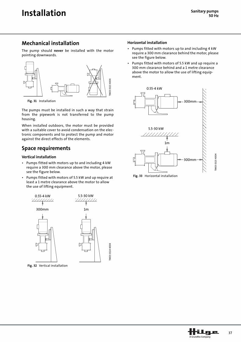
Sanitary pumps50 Hz
InstallationMechanical installationThe pump should never be installed with the motorpointing downwards.
Fig. 31 Installation
The pumps must be installed in such a way that strainfrom the pipework is not transferred to the pumphousing.
When installed outdoors, the motor must be providedwith a suitable cover to avoid condensation on the elec-tronic components and to protect the pump and motoragainst the direct effects of the elements.
Space requirements
Vertical installation
• Pumps fitted with motors up to and including 4 kW require a 300 mm clearance above the motor, please see the figure below.
• Pumps fitted with motors of 5.5 kW and up require at least a 1 metre clearance above the motor to allow the use of lifting equipment.
Fig. 32 Vertical installation
Horizontal installation
• Pumps fitted with motors up to and including 4 kW require a 300 mm clearance behind the motor, please see the figure below.
• Pumps fitted with motors of 5.5 kW and up require a 300 mm clearance behind and a 1 metre clearance above the motor to allow the use of lifting equip-ment.
Fig. 33 Horizontal installation
TM0
3 0
113
400
4TM
03
011
4 40
04
300mm 1m
0.55-4 kW 5.5-30 kW
TM0
3 0
115
400
4
0.55-4 kW
300mm
5.5-30 kW
1m
300mm
37

38
Installation
Sanitary pumps50 HzFoundation and vibration dampeningIn order to achieve optimum operation and to reducenoise and vibration to a minimum, it may be necessaryto consider vibration dampening of the pump in certaincases. Generally this should always be considered in thecase of pumps with motors larger than 11 kW. Smallermotors, however, may also cause undesirable noise andvibration.
Noise and vibration are generated by the rotations in themotor and pump and by the flow in pipes and fittings.The effect on the environment is subjective and dependson correct installation and the state of the remainingsystem.
Foundation
Pumps should be installed on a plane and rigid concretefoundation which is the optimum solution for vibrationdampening.
Fig. 34 Example of foundation of a Contra II pump
As a rule of thumb, the weight of a concrete foundationshould be 1.5 x the pump weight.
Dampening
To prevent the transmission of vibrations to buildings, itis advisable to isolate the pump foundation frombuilding parts by means of vibration dampers.
The selection of the right vibration damper requires thefollowing data:
• forces transmitted through the damper
• motor speed considering speed control, if any
• required dampening in % (suggested value is 70%).
Which is the right damper varies from installation toinstallation, and a wrong damper may increase thevibration level. Vibration dampers should therefore besized by the supplier.
If the pump is installed on a pedestal with vibrationdampers, expansion joints should always be fitted onthe pump flanges. This is important to prevent the pumpfrom "hanging" in the flanges.
Expansion joints
Expansion joints are installed to
• absorb expansions/contractions in the pipework caused by changing liquid temperature
• reduce mechanical strains in connection with pres-sure surges in the pipework
• isolate mechanical structure-borne noise in the pipe-work (only rubber bellows expansion joints).
Note: Expansion joints must not be installed to compen-sate for inaccuracies in the pipework such as centredisplacement of flanges.
Fit expansion joints at a distance of minimum 1 to 1½ xDN diameter from the pump on the suction as well as onthe discharge side. This prevents the development ofturbulence in the expansion joints, resulting in bettersuction conditions and a minimum pressure loss on thepressure side. At high water velocities (> 5 m/s) it isadvisable to install larger expansion joints corre-sponding to the pipework.
Expansion joints with limit rods can be used to minimizethe forces caused by the expansion joints. Expansionjoints with limit rods are always recommended forflanges larger than DN 100.
The pipes should be anchored so that they do not stressthe expansion joints and the pump. Follow the supplier’sinstructions and pass them on to advisers or pipeinstallers.
Terminal box positionsThe below terminal box positions are possible for allpump ranges.
Fig. 35 Possible terminal box positions
TM0
3 0
116
40
04
Expansion
joints
Concrete foundation
Vibration dampers
TM0
3 0
117
400
4
12 o’clock 3 o’clock 9 o’clock On fan cover(Bloc-SUPER)
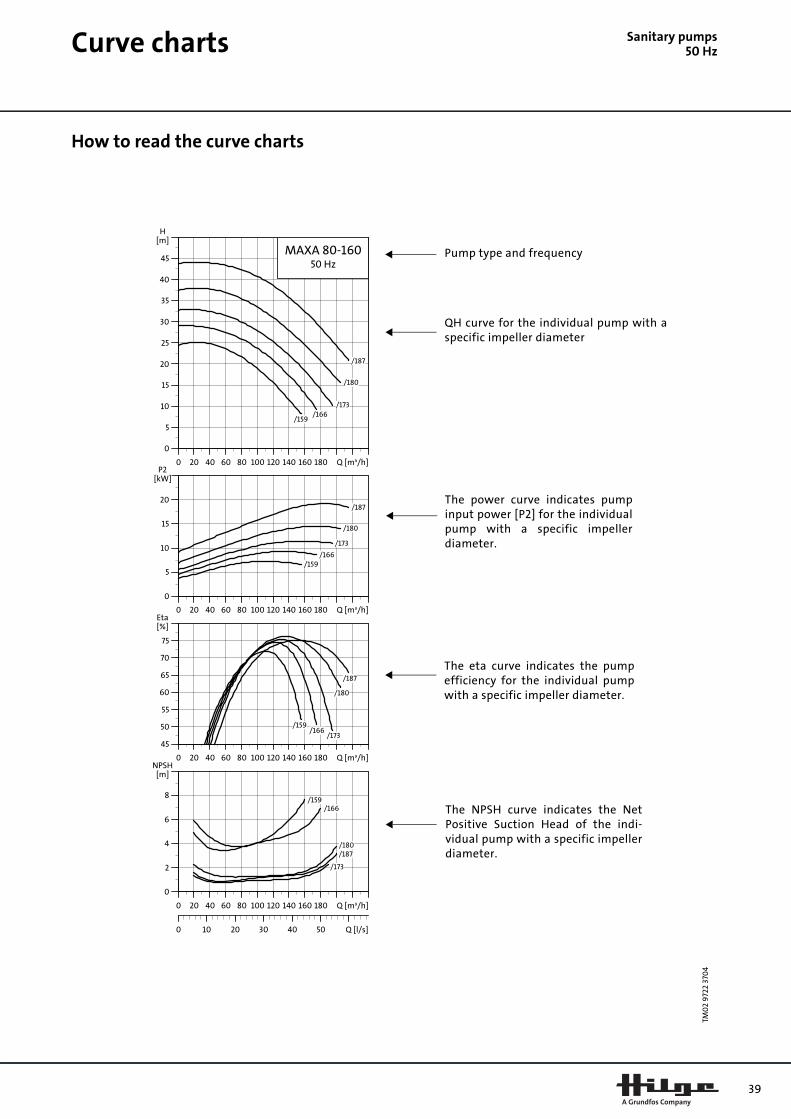
Sanitary pumps50 Hz
Curve chartsHow to read the curve charts
TM0
2 9
722
370
4
0 20 40 60 80 100 120 140 160 180 Q [m³/h]
0
5
10
15
20
25
30
35
40
45
H[m]
MAXA 80-16050 Hz
/159/166
/173
/180
/187
0 20 40 60 80 100 120 140 160 180 Q [m³/h]
0
5
10
15
20
P2[kW]
/159/166
/173
/180
/187
0 20 40 60 80 100 120 140 160 180 Q [m³/h]
45
50
55
60
65
70
75
[%]Eta
/159/166
/173
/180
/187
0 20 40 60 80 100 120 140 160 180 Q [m³/h]
0
2
4
6
8
[m]NPSH
0 10 20 30 40 50 Q [l/s]
/159/166
/173
/180/187
Pump type and frequency
QH curve for the individual pump with aspecific impeller diameter
The power curve indicates pumpinput power [P2] for the individualpump with a specific impellerdiameter.
The eta curve indicates the pumpefficiency for the individual pumpwith a specific impeller diameter.
The NPSH curve indicates the NetPositive Suction Head of the indi-vidual pump with a specific impellerdiameter.
39
40
Curve charts
Sanitary pumps50 HzCurve conditionsThe guidelines below apply to the curves shown on the following pages:
1. Tolerances to ISO 9906, Annex A.
2. QH curves of the individual pumps are shown with expected speed of a three-phase standard motor.
3. Measurements have been made with airless water at a temperature of +20°C.
4. The curves apply to a kinematic viscosity ofυ = 1 mm2/s (1 cSt).
5. If the pumped liquid density and/or viscosity is higher than that of water, it may be necessary to use a motor with a higher performance.

Euro-HYGIA® I50 Hz
Performance curvesEuro-HYGIA® I, 2-pole Euro-HYGIA® I, 4-pole
TM0
2 9
742
370
4
0 4 8 12 16 20 24 28 32 Q [m³/h]
0
5
10
15
20
25
30
35
40
45
50
55
H[m]
Euro-HYGIA I50 Hz
/185
/155
/120
0 4 8 12 16 20 24 28 32 Q [m³/h]
0
1
2
3
4
5
6
7
P2[kW]
/185
/155
/120
0 4 8 12 16 20 24 28 32 Q [m³/h]
25
30
35
40
45
50
55
60
[%]Eta
/185
/155
/120
0 4 8 12 16 20 24 28 32 Q [m³/h]
0.0
0.5
1.0
1.5
2.0
2.5
[m]NPSH
0 2 4 6 8 10 Q [l/s]
/185
/155
/120
TM0
2 9
741
370
4Per
form
ance
curv
es/
T
ech
nic
ald
ata
Euro
-HY
GIA
® I
0 2 4 6 8 10 12 14 16 18Q [m³/h]
0
1
2
3
4
5
6
7
8
9
10
11
12
H[m]
Euro-HYGIA I50 Hz
/130
/155
/185
0 2 4 6 8 10 12 14 16 18Q [m³/h]
0.0
0.1
0.2
0.3
0.4
0.5
0.6
0.7
0.8
P2[kW]
/130
/155
/185
0 2 4 6 8 10 12 14 16 18Q [m³/h]
25
30
35
40
45
50
55
60
[%]Eta
/130
/155
/185
0 2 4 6 8 10 12 14 16 18Q [m³/h]
0.0
0.5
1.0
1.5
2.0
2.5
[m]NPSH
0 1 2 3 4 5 Q [l/s]
/130
/155/185
41
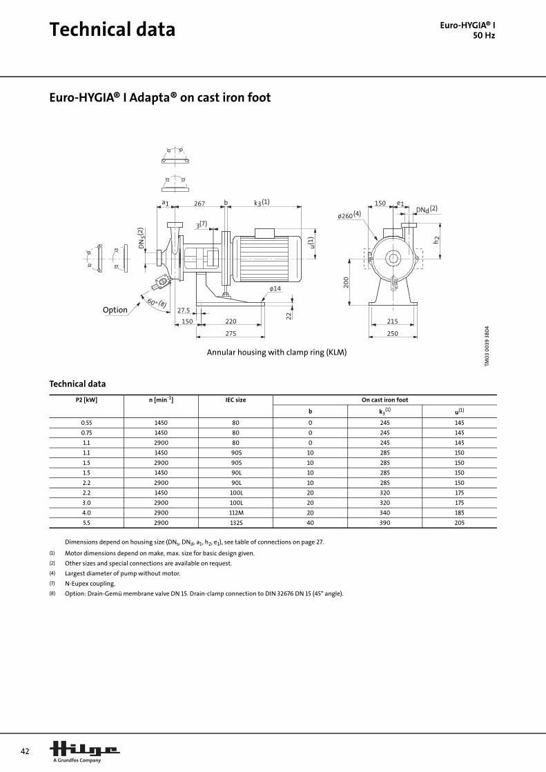
42
Technical data
Euro-HYGIA® I50 HzEuro-HYGIA® I Adapta® on cast iron foot
Technical data
TM0
3 0
039
380
4
Annular housing with clamp ring (KLM)
Option
P2 [kW] n [min-1] IEC size On cast iron foot
b k3(1) u(1)
0.55 1450 80 0 245 145
0.75 1450 80 0 245 145
1.1 2900 80 0 245 145
1.1 1450 90S 10 285 150
1.5 2900 90S 10 285 150
1.5 1450 90L 10 285 150
2.2 2900 90L 10 285 150
2.2 1450 100L 20 320 175
3.0 2900 100L 20 320 175
4.0 2900 112M 20 340 185
5.5 2900 132S 40 390 205
Dimensions depend on housing size (DNs, DNd, a1, h2, e1), see table of connections on page 27.
(1) Motor dimensions depend on make, max. size for basic design given.
(2) Other sizes and special connections are available on request.
(4) Largest diameter of pump without motor.
(7) N-Eupex coupling.
(8) Option: Drain-Gemü membrane valve DN 15. Drain-clamp connection to DIN 32676 DN 15 (45° angle).

Technical data
Euro-HYGIA® I50 HzEuro-HYGIA® I Adapta® SUPER on stainless steel combi-foot (frame size 80-90)
Technical data
TM0
3 0
040
380
4
Annular housing with clamp ring (KLM)
Option
P2 [kW] n [min-1] IEC size On stainless steel combi-foot
lH hH Ø dH
0.55 1450 80 370 180 320
0.75 1450 80 370 180 320
1.1 2900 80 370 180 320
1.1 1450 90S 370 180 320
1.5 2900 90S 370 180 320
1.5 1450 90L 370 180 320
2.2 2900 90L 370 180 320
Dimensions depend on housing size (DNs, DNd, a1, h2, e1), see table of connections on page 27.
(2) Other sizes and special connections are available on request.
(4) Largest diameter of pump without motor.
(7) N-Eupex coupling.
(8) Option: Drain-Gemü membrane valve DN 15. Drain-clamp connection to DIN 32 676 DN 15 (45° angle).
43
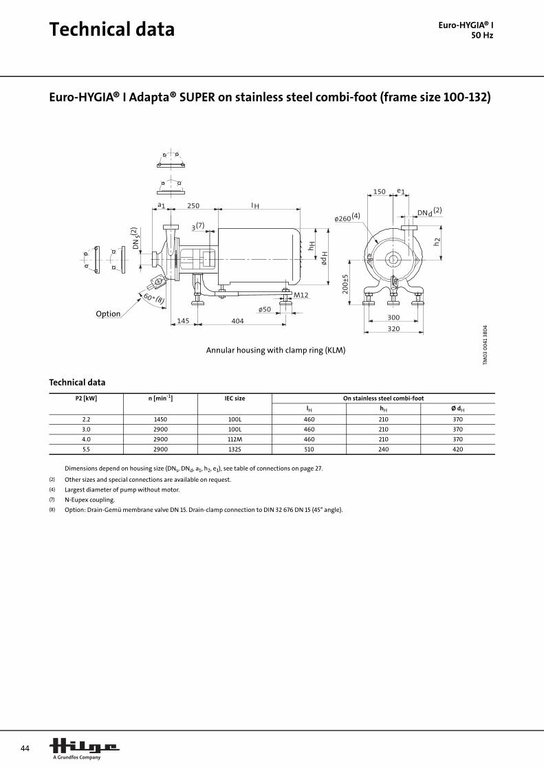
44
Technical data
Euro-HYGIA® I50 HzEuro-HYGIA® I Adapta® SUPER on stainless steel combi-foot (frame size 100-132)
Technical data
TM0
3 0
041
380
4
Annular housing with clamp ring (KLM)
Option
P2 [kW] n [min-1] IEC size On stainless steel combi-foot
lH hH Ø dH
2.2 1450 100L 460 210 370
3.0 2900 100L 460 210 370
4.0 2900 112M 460 210 370
5.5 2900 132S 510 240 420
Dimensions depend on housing size (DNs, DNd, a1, h2, e1), see table of connections on page 27.
(2) Other sizes and special connections are available on request.
(4) Largest diameter of pump without motor.
(7) N-Eupex coupling.
(8) Option: Drain-Gemü membrane valve DN 15. Drain-clamp connection to DIN 32 676 DN 15 (45° angle).
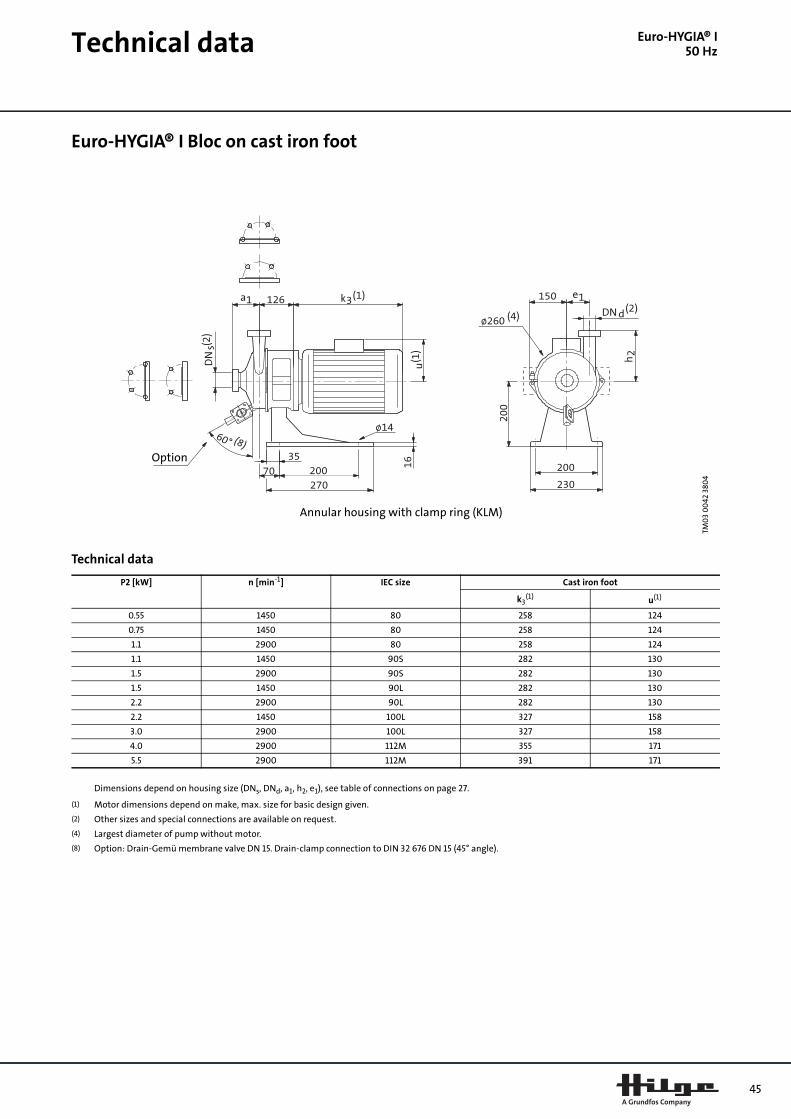
Technical data
Euro-HYGIA® I50 HzEuro-HYGIA® I Bloc on cast iron foot
Technical data
TM0
3 0
042
380
4
Annular housing with clamp ring (KLM)
Option
P2 [kW] n [min-1] IEC size Cast iron foot
k3(1) u(1)
0.55 1450 80 258 124
0.75 1450 80 258 124
1.1 2900 80 258 124
1.1 1450 90S 282 130
1.5 2900 90S 282 130
1.5 1450 90L 282 130
2.2 2900 90L 282 130
2.2 1450 100L 327 158
3.0 2900 100L 327 158
4.0 2900 112M 355 171
5.5 2900 112M 391 171
Dimensions depend on housing size (DNs, DNd, a1, h2, e1), see table of connections on page 27.
(1) Motor dimensions depend on make, max. size for basic design given.
(2) Other sizes and special connections are available on request.
(4) Largest diameter of pump without motor.
(8) Option: Drain-Gemü membrane valve DN 15. Drain-clamp connection to DIN 32 676 DN 15 (45° angle).
45
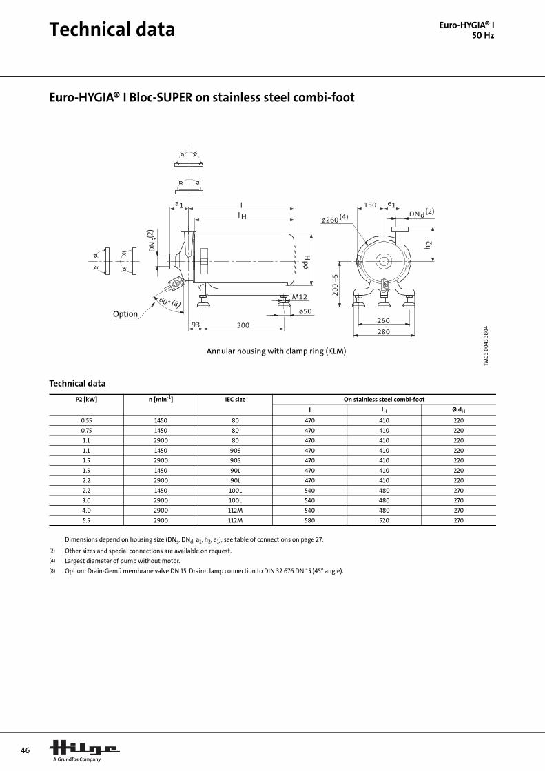
46
Technical data
Euro-HYGIA® I50 HzEuro-HYGIA® I Bloc-SUPER on stainless steel combi-foot
Technical data
TM0
3 0
043
380
4
Annular housing with clamp ring (KLM)
Option
P2 [kW] n [min-1] IEC size On stainless steel combi-foot
l lH Ø dH
0.55 1450 80 470 410 220
0.75 1450 80 470 410 220
1.1 2900 80 470 410 220
1.1 1450 90S 470 410 220
1.5 2900 90S 470 410 220
1.5 1450 90L 470 410 220
2.2 2900 90L 470 410 220
2.2 1450 100L 540 480 270
3.0 2900 100L 540 480 270
4.0 2900 112M 540 480 270
5.5 2900 112M 580 520 270
Dimensions depend on housing size (DNs, DNd, a1, h2, e1), see table of connections on page 27.
(2) Other sizes and special connections are available on request.
(4) Largest diameter of pump without motor.
(8) Option: Drain-Gemü membrane valve DN 15. Drain-clamp connection to DIN 32 676 DN 15 (45° angle).

Performance curves
Euro-HYGIA® II50 HzEuro-HYGIA® II, 2-pole Euro-HYGIA® II, 4-pole
TM0
2 9
746
370
4
0 10 20 30 40 50 60 70 80 90 Q [m³/h]
0
10
20
30
40
50
60
70
80
90
H[m]
Euro-HYGIA II50 Hz
/190
/210
/230
0 10 20 30 40 50 60 70 80 90 Q [m³/h]
0
5
10
15
20
25
30
P2[kW]
/190
/210
/230
0 10 20 30 40 50 60 70 80 90 Q [m³/h]
35
40
45
50
55
60
65
70
[%]Eta
/190/210
/230
0 10 20 30 40 50 60 70 80 90 Q [m³/h]
0
1
2
3
4
5
[m]NPSH
0 5 10 15 20 25 Q [l/s]
/190/210
/230
TM0
2 9
745
370
4Eu
ro-H
YGIA
® II
0 5 10 15 20 25 30 35 40 45 Q [m³/h]
0
2
4
6
8
10
12
14
16
18
20
H[m]
Euro-HYGIA II50 Hz
/190
/210
/230
0 5 10 15 20 25 30 35 40 45 Q [m³/h]
0.0
0.5
1.0
1.5
2.0
2.5
3.0
3.5
P2[kW]
/190
/210
/230
0 5 10 15 20 25 30 35 40 45 Q [m³/h]
35
40
45
50
55
60
65
70
[%]Eta
/190
/210
/230
0 5 10 15 20 25 30 35 40 45 Q [m³/h]
0.0
0.5
1.0
1.5
2.0
2.5
3.0
[m]NPSH
0 2 4 6 8 10 12 14 Q [l/s]
/190
/210
/230
47

48
Technical data
Euro-HYGIA® II50 HzEuro-HYGIA® II Adapta® on Adapta® foot (frame size 180M)
Technical data
TM0
3 0
056
380
4
Annular housing with clamp ring (KLM)
Option
P2 [kW] n [min-1] IEC size On cast iron foot
k3(1) u(1)
22.0 2900 180M 605 265
Dimensions depend on housing size (DNs, DNd, a1, h2, e1), see table of connections on page 28.
(1) Motor dimensions depend on make, max. size for basic design given.
(2) Other sizes and special connections are available on request.
(4) Largest diameter of pump without motor.
(7) N-Eupex coupling.
(8) Option: Drain-Gemü membrane valve DN 15. Drain-clamp connection to DIN 32 676 DN 15 (45° angle).
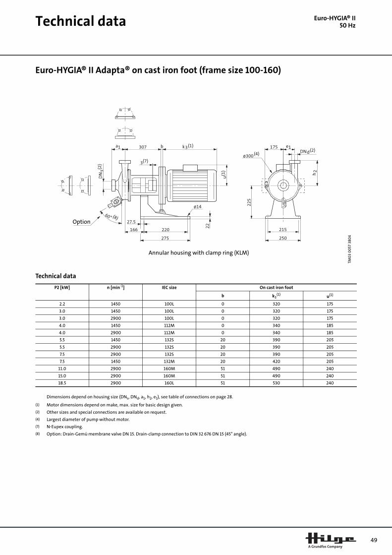
Technical data
Euro-HYGIA® II50 HzEuro-HYGIA® II Adapta® on cast iron foot (frame size 100-160)
Technical data
TM0
3 0
057
380
4
Annular housing with clamp ring (KLM)
Option
P2 [kW] n [min-1] IEC size On cast iron foot
b k3(1) u(1)
2.2 1450 100L 0 320 175
3.0 1450 100L 0 320 175
3.0 2900 100L 0 320 175
4.0 1450 112M 0 340 185
4.0 2900 112M 0 340 185
5.5 1450 132S 20 390 205
5.5 2900 132S 20 390 205
7.5 2900 132S 20 390 205
7.5 1450 132M 20 420 205
11.0 2900 160M 51 490 240
15.0 2900 160M 51 490 240
18.5 2900 160L 51 530 240
Dimensions depend on housing size (DNs, DNd, a1, h2, e1), see table of connections on page 28.
(1) Motor dimensions depend on make, max. size for basic design given.
(2) Other sizes and special connections are available on request.
(4) Largest diameter of pump without motor.
(7) N-Eupex coupling.
(8) Option: Drain-Gemü membrane valve DN 15. Drain-clamp connection to DIN 32 676 DN 15 (45° angle).
49

50
Technical data
Euro-HYGIA® II50 HzEuro-HYGIA® II Adapta® SUPER on stainless steel combi-foot (frame size 100-160)
Technical data
TM0
3 0
059
380
4
Annular housing with clamp ring (KLM)
Option
P2 [kW] n [min-1] IEC size On stainless steel combi-foot
lH hH Ø dH
2.2 1450 100L 510 240 420
3.0 1450 100L 510 240 420
3.0 2900 100L 510 240 420
4.0 1450 112M 510 240 420
4.0 2900 112M 510 240 420
5.5 1450 132S 510 240 420
5.5 2900 132S 510 240 420
7.5 2900 132S 510 240 420
7.5 1450 132M 510 240 420
11.0 2900 160M 650 285 485
15.0 2900 160M 650 285 485
18.5 2900 160L 650 285 485
Dimensions depend on housing size (DNs, DNd, a1, h2, e1), see table of connections on page 28.
(2) Other sizes and special connections are available on request.
(4) Largest diameter of pump without motor.
(7) N-Eupex coupling.
(8) Option: Drain-Gemü membrane valve DN 15. Drain-clamp connection to DIN 32 676 DN 15 (45° angle).

Technical data
Euro-HYGIA® II50 HzEuro-HYGIA® II Adapta® SUPER on machine pads (frame size 180)
Technical data
TM0
3 0
058
380
4
Annular housing with clamp ring (KLM)
Option
P2 [kW] n [min-1] IEC size
22.0 2900 180M
Dimensions depend on housing size (DNs, DNd, a1, h2, e1), see table of connections on page 28.
(2) Other sizes and special connections are available on request.
(4) Largest diameter of pump without motor.
(7) N-Eupex coupling.
(8) Option: Drain-Gemü membrane valve DN 15. Drain-clamp connection to DIN 32 676 DN 15 (45° angle).
51
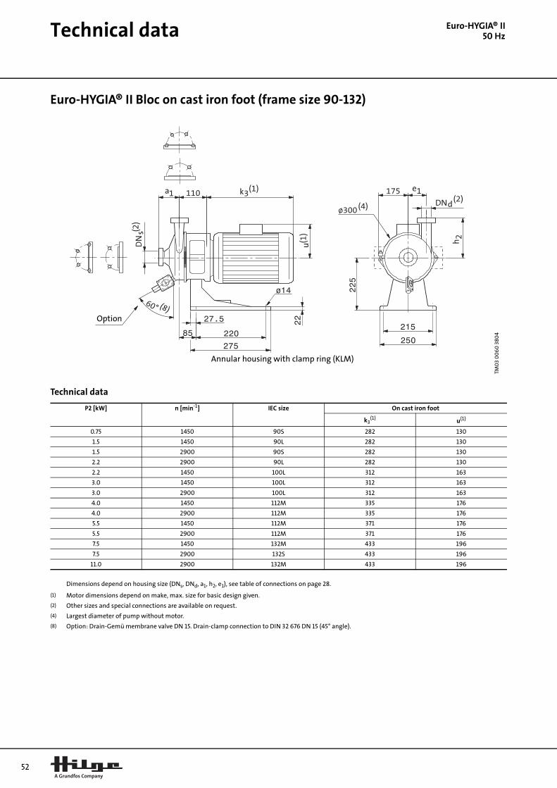
52
Technical data
Euro-HYGIA® II50 HzEuro-HYGIA® II Bloc on cast iron foot (frame size 90-132)
Technical data
TM0
3 0
06
0 3
804
Annular housing with clamp ring (KLM)
275225
215
ø14
85250
2227.5
220
Option
P2 [kW] n [min-1] IEC size On cast iron foot
k3(1) u(1)
0.75 1450 90S 282 130
1.5 1450 90L 282 130
1.5 2900 90S 282 130
2.2 2900 90L 282 130
2.2 1450 100L 312 163
3.0 1450 100L 312 163
3.0 2900 100L 312 163
4.0 1450 112M 335 176
4.0 2900 112M 335 176
5.5 1450 112M 371 176
5.5 2900 112M 371 176
7.5 1450 132M 433 196
7.5 2900 132S 433 196
11.0 2900 132M 433 196
Dimensions depend on housing size (DNs, DNd, a1, h2, e1), see table of connections on page 28.
(1) Motor dimensions depend on make, max. size for basic design given.
(2) Other sizes and special connections are available on request.
(4) Largest diameter of pump without motor.
(8) Option: Drain-Gemü membrane valve DN 15. Drain-clamp connection to DIN 32 676 DN 15 (45° angle).

Technical data
Euro-HYGIA® II50 HzEuro-HYGIA® II Bloc on motor foot with stainless steel plinth (frame size 160)
Technical data
TM0
3 0
06
1 38
04
Annular housing with clamp ring (KLM)
Option
P2 [kW] n [min-1] IEC size On motor foot with stainless steel plinth
k3(1) u(1) m1 m2 ø s n1 n2
15.0 2900 160M 522 226 310 250 13 410 380
18.5 2900 160L 562 226 310 250 13 410 380
22.0 2900 160L 562 226 310 250 13 410 380
Dimensions depend on housing size (DNs, DNd, a1, h2, e1), see table of connections on page 28.
(1) Motor dimensions depend on make, max. size for basic design given.
(2) Other sizes and special connections are available on request.
(4) Largest diameter of pump without motor.
(8) Option: Drain-Gemü membrane valve DN 15. Drain-clamp connection to DIN 32 676 DN 15 (45° angle).
53

54
Technical data
Euro-HYGIA® II50 HzEuro-HYGIA® II Bloc-SUPER on stainless steel combi-foot (frame size 90-132)
Technical data
TM0
3 0
06
2 38
04
Annular housing with clamp ring (KLM)
Option
P2 [kW] n [min-1] IEC size On stainless steel combi-foot
l lH Ø dH
0.75 1450 90S 540 480 270
1.5 1450 90L 540 480 270
1.5 2900 90S 540 480 270
2.2 2900 90L 540 480 270
2.2 1450 100L 540 480 270
3.0 1450 100L 540 480 270
3.0 2900 100L 540 480 270
4.0 1450 112M 540 480 270
4.0 2900 112M 540 480 270
5.5 1450 112M 580 520 270
5.5 2900 112M 580 520 270
7.5 1450 132M 660 600 320
7.5 2900 132S 660 600 320
11.0 2900 132M 660 600 320
Dimensions depend on housing size (DNs, DNd, a1, h2, e1), see table of connections on page 28.
(2) Other sizes and special connections are available on request.
(4) Largest diameter of pump without motor.
(8) Option: Drain-Gemü membrane valve DN 15. Drain-clamp connection to DIN 32 676 DN 15 (45° angle).
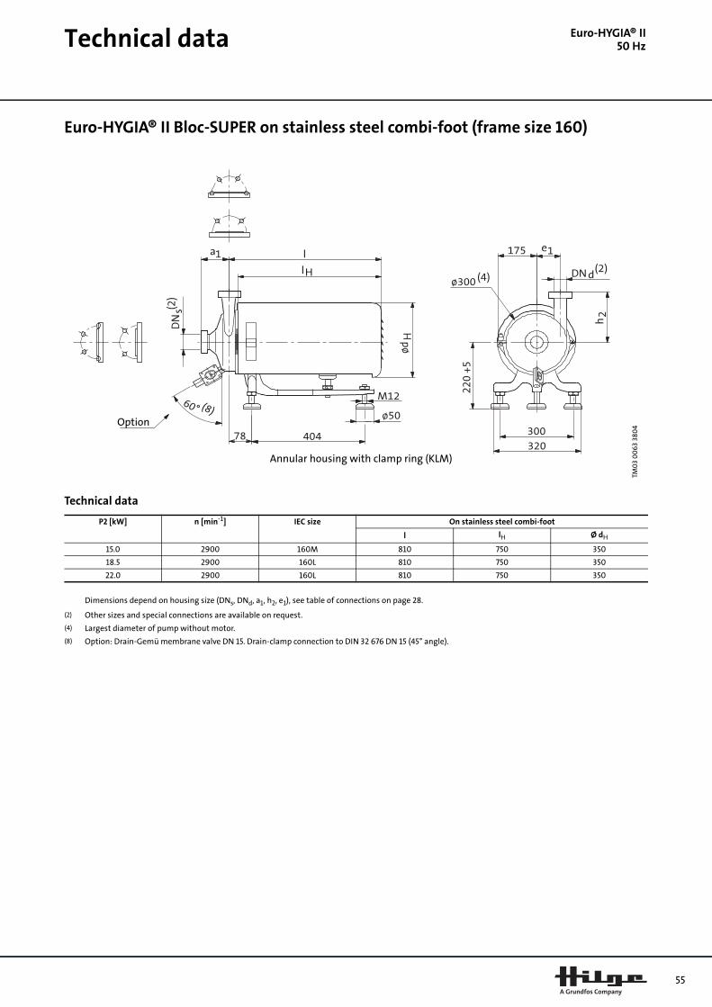
Technical data
Euro-HYGIA® II50 HzEuro-HYGIA® II Bloc-SUPER on stainless steel combi-foot (frame size 160)
Technical data
TM0
3 0
06
3 38
04
Annular housing with clamp ring (KLM)
Option
P2 [kW] n [min-1] IEC size On stainless steel combi-foot
l lH Ø dH
15.0 2900 160M 810 750 350
18.5 2900 160L 810 750 350
22.0 2900 160L 810 750 350
Dimensions depend on housing size (DNs, DNd, a1, h2, e1), see table of connections on page 28.
(2) Other sizes and special connections are available on request.
(4) Largest diameter of pump without motor.
(8) Option: Drain-Gemü membrane valve DN 15. Drain-clamp connection to DIN 32 676 DN 15 (45° angle).
55

56
Performance curves
Contra I50 HzContra I, 2-pole
TM0
2 9
749
370
4Co
ntr
a I
0 2 4 6 8 10 12 14 16 18 20 Q [m³/h]
0
10
20
30
40
50
60
70
80
90
100
110
H[m]
Contra I50 Hz
-1
-2
-3
-4
-5
-6
0 2 4 6 8 10 12 14 16 18 20 Q [m³/h]
0
1
2
3
4
5
6
P2[kW]
-1
-2
-3
-4
-5
-6
0 2 4 6 8 10 12 14 16 18 20 Q [m³/h]
20
25
30
35
40
45
50
55
[%]Eta
-1
-2
-3
-4
-5
-6
0 2 4 6 8 10 12 14 16 18 20 Q [m³/h]
0
1
2
3
4
5
[m]NPSH
0 1 2 3 4 5 6 Q [l/s]
-1
-2
-3
-4-5
-6

Technical data
Contra I50 HzContra I Adapta® on cast iron foot
Technical data
TM0
3 0
06
4 38
04
P2 [kW] n [min-1] IEC size On cast iron foot
b k3(1) u(1)
0.55 1450 80 0 245 145
0.75 1450 80 0 245 145
0.75 2900 80 0 245 145
1.1 2900 80 0 245 145
1.1 1450 90S 10 285 150
1.5 2900 90S 10 285 150
1.5 1450 90L 10 285 150
2.2 2900 90L 10 285 150
2.2 1450 100L 20 320 175
3.0 2900 100L 20 320 175
4.0 2900 112M 20 340 185
5.5 2900 132S 40 390 205
Dimensions depend on housing size (DNs, DNd, a1, f2, h2), see table of connections on page 29.
(1) Motor dimensions depend on make, max. size for basic design given.
(2) Other sizes and special connections are available on request.
(4) Largest diameter of pump without motor.
(7) Coupling of our choice.
57

58
Technical data
Contra I50 HzContra I Adapta® SUPER on stainless steel combi-foot (frame size 80-90)
Technical data
TM0
3 0
06
5 38
04
P2 [kW] n [min-1] IEC size On stainless steel combi-foot
lH hH Ø dH
0.55 1450 80 370 180 320
0.75 1450 80 370 180 320
0.75 2900 80 370 180 320
1.1 2900 80 370 180 320
1.1 1450 90S 370 180 320
1.5 2900 90S 370 180 320
1.5 1450 90L 370 180 320
2.2 2900 90L 370 180 320
Dimensions depend on housing size (DNs, DNd, a1, f2, h2), see table of connections on page 29.
(2) Other sizes and special connections are available on request.
(4) Largest diameter of pump without motor.
(7) Coupling of our choice.
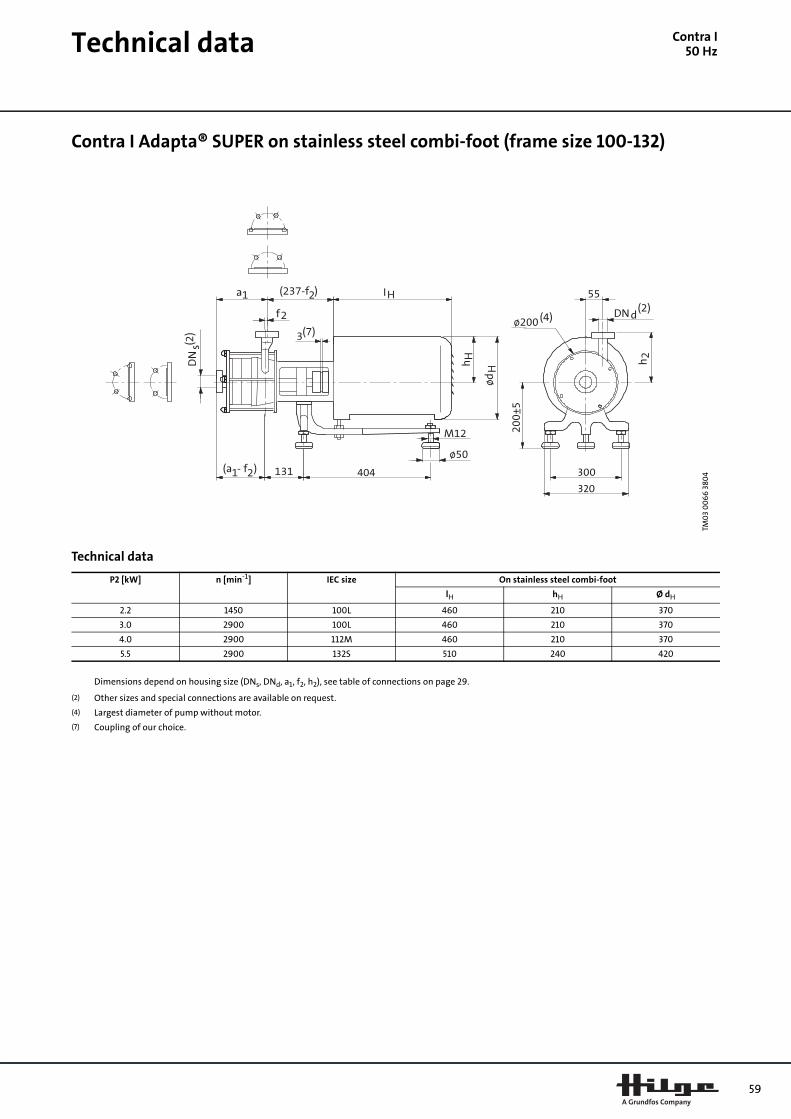
Technical data
Contra I50 HzContra I Adapta® SUPER on stainless steel combi-foot (frame size 100-132)
Technical data
TM0
3 0
06
6 3
804404 300
320
P2 [kW] n [min-1] IEC size On stainless steel combi-foot
lH hH Ø dH
2.2 1450 100L 460 210 370
3.0 2900 100L 460 210 370
4.0 2900 112M 460 210 370
5.5 2900 132S 510 240 420
Dimensions depend on housing size (DNs, DNd, a1, f2, h2), see table of connections on page 29.
(2) Other sizes and special connections are available on request.
(4) Largest diameter of pump without motor.
(7) Coupling of our choice.
59

60
Technical data
Contra I50 HzContra I Adapta®-V on stainless steel pedestal with/without suction elbow
Technical data
TM0
3 0
06
7 38
04
For installing, removing and servicing the pump lifting points should be foreseen directlyabove the pump and removable lengths incorporate into the suction line.
P2 [kW] n [min-1] IEC size On stainless steel pedestal with/without suction elbow
b k3(1) u(1)
0.55 1450 80 0 245 145
0.75 1450 80 0 245 145
0.75 2900 80 0 245 145
1.1 2900 80 0 245 145
1.1 1450 90S 10 285 150
1.5 2900 90S 10 285 150
1.5 1450 90L 10 285 150
2.2 2900 90L 10 285 150
2.2 1450 100L 20 320 175
3.0 2900 100L 20 320 175
4.0 2900 112M 20 340 185
5.5 2900 132S 40 390 205
Dimensions depend on housing size (DNs, DNd, a1, e5, f2, h2, h3), see table of connections on page 29.
(1) Motor dimensions depend on make, max. size for basic design given.
(2) Other sizes and special connections are available on request.
(4) Largest diameter of pump without motor.
(7) Coupling of our choice.

Technical data
Contra I50 HzContra I Bloc on cast iron foot
Technical data
TM0
3 0
06
8 38
04
P2 [kW] n [min-1] IEC size On cast iron foot
k3(1) u(1)
0.55 1450 80 258 124
0.75 1450 80 258 124
0.75 2900 80 258 124
1.1 2900 80 258 124
1.1 1450 90S 282 130
1.5 2900 90S 282 130
1.5 1450 90L 282 130
2.2 2900 90L 282 130
2.2 1450 100L 332 158
3.0 2900 100L 332 158
4.0 2900 112M 391 171
5.5 2900 112M 391 171
Dimensions depend on housing size (DNs, DNd, a1, f2, h2), see table of connections on page 29.
(1) Motor dimensions depend on make, max. size for basic design given.
(2) Other sizes and special connections are available on request.
(4) Largest diameter of pump without motor.
61

62
Technical data
Contra I50 HzContra I Bloc-SUPER on stainless steel combi-foot
Technical data
TM0
3 0
06
9 3
804
P2 [kW] n [min-1] IEC size On stainless steel combi-foot
lH Ø dH
0.55 1450 80 410 220
0.75 1450 80 410 220
0.75 2900 80 410 220
1.1 2900 80 410 220
1.1 1450 90S 410 220
1.5 2900 90S 410 220
1.5 1450 90L 410 220
2.2 2900 90L 410 220
2.2 1450 100L 480 270
3.0 2900 100L 480 270
4.0 2900 112M 520 270
5.5 2900 112M 520 270
Dimensions depend on housing size (DNs, DNd, a1, f2, h2), see table of connections on page 29.
(2) Other sizes and special connections are available on request.
(4) Largest diameter of pump without motor.
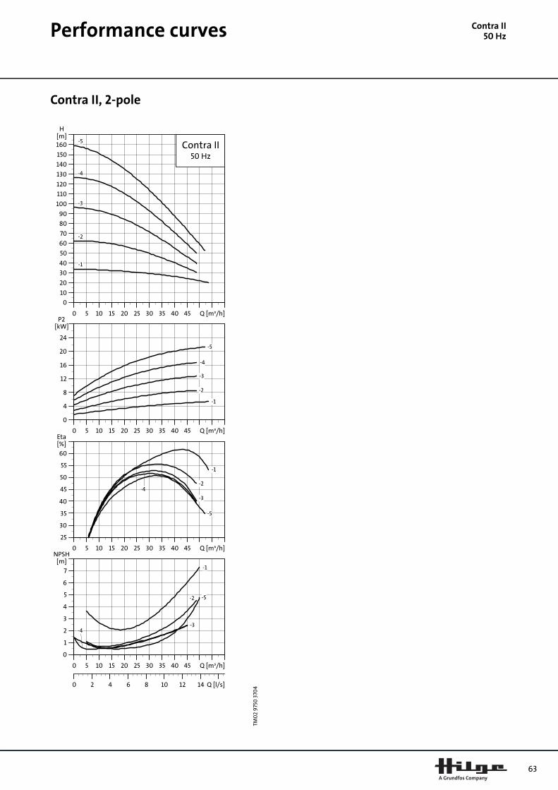
Performance curves
Contra II50 HzContra II, 2-pole
TM0
2 9
750
370
4Co
ntr
a II
0 5 10 15 20 25 30 35 40 45 Q [m³/h]
0
10
20
30
40
50
60
70
80
90
100
110
120
130
140
150
160
H[m]
Contra II50 Hz
-1
-2
-3
-4
-5
0 5 10 15 20 25 30 35 40 45 Q [m³/h]
0
4
8
12
16
20
24
P2[kW]
-1
-2
-3
-4
-5
0 5 10 15 20 25 30 35 40 45 Q [m³/h]
25
30
35
40
45
50
55
60
[%]Eta
-1
-2
-3
-4
-5
0 5 10 15 20 25 30 35 40 45 Q [m³/h]
0
1
2
3
4
5
6
7
[m]NPSH
0 2 4 6 8 10 12 14 Q [l/s]
-1
-2
-3-4
-5
63
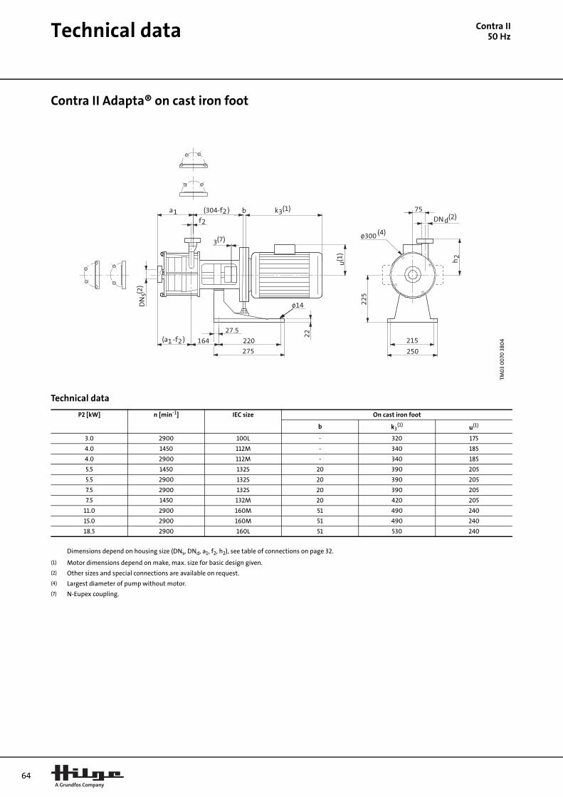
64
Technical data
Contra II50 HzContra II Adapta® on cast iron foot
Technical data
TM0
3 0
070
380
4
P2 [kW] n [min-1] IEC size On cast iron foot
b k3(1) u(1)
3.0 2900 100L - 320 175
4.0 1450 112M - 340 185
4.0 2900 112M - 340 185
5.5 1450 132S 20 390 205
5.5 2900 132S 20 390 205
7.5 2900 132S 20 390 205
7.5 1450 132M 20 420 205
11.0 2900 160M 51 490 240
15.0 2900 160M 51 490 240
18.5 2900 160L 51 530 240
Dimensions depend on housing size (DNs, DNd, a1, f2, h2), see table of connections on page 32.
(1) Motor dimensions depend on make, max. size for basic design given.
(2) Other sizes and special connections are available on request.
(4) Largest diameter of pump without motor.
(7) N-Eupex coupling.
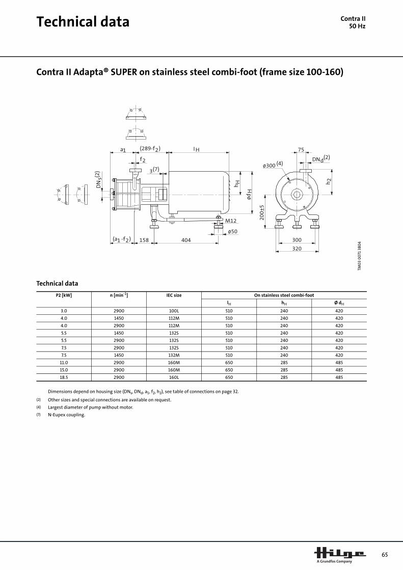
Technical data
Contra II50 HzContra II Adapta® SUPER on stainless steel combi-foot (frame size 100-160)
Technical data
TM0
3 0
071
380
4
P2 [kW] n [min-1] IEC size On stainless steel combi-foot
lH hH Ø dH
3.0 2900 100L 510 240 420
4.0 1450 112M 510 240 420
4.0 2900 112M 510 240 420
5.5 1450 132S 510 240 420
5.5 2900 132S 510 240 420
7.5 2900 132S 510 240 420
7.5 1450 132M 510 240 420
11.0 2900 160M 650 285 485
15.0 2900 160M 650 285 485
18.5 2900 160L 650 285 485
Dimensions depend on housing size (DNs, DNd, a1, f2, h2), see table of connections on page 32.
(2) Other sizes and special connections are available on request.
(4) Largest diameter of pump without motor.
(7) N-Eupex coupling.
65

66
Technical data
Contra II50 HzContra II Adapta®-V on stainless steel pedestal with/without suction elbow (frame size 100-160)
Technical data
TM0
3 0
072
380
4
For installing, removing and servicing the pump, lifting points should be foreseen directlyabove the pump and removable lengths incorporated into the suction line.Discharge port is asymmetric; the pump can be drained completely.
P2 [kW] n [min-1] IEC size On stainless steel pedestal with/without suction elbow
b k3(1) u(1)
2.2 1450 100L 0 320 175
3.0 1450 100L 0 320 175
3.0 2900 100L 0 320 175
4.0 1450 112M 0 340 185
4.0 2900 112M 0 340 185
5.5 1450 132S 20 390 205
5.5 2900 132S 20 390 205
7.5 2900 132S 20 390 205
7.5 1450 132M 20 420 205
11.0 2900 160M 51 490 240
15.0 2900 160M 51 490 240
18.5 2900 160L 51 530 240
Dimensions depend on housing size (DNs, DNd, a1, f2, h2, h3, e1, e5), see table of connections on page 32.
(1) Motor dimensions depend on make, max. size for basic design given.
(2) Other sizes and special connections are available on request.
(7) N-Eupex coupling.

Technical data
Contra II50 HzContra II Bloc on cast iron foot (frame size 90-132)
Technical data
TM0
3 0
073
380
4
P2 [kW] n [min-1] IEC size On cast iron foot
k3(1) u(1)
0.75 1450 90S 282 130
1.1 1450 90S 282 130
1.5 1450 90L 282 130
1.5 2900 90S 282 130
2.2 2900 90L 282 130
2.2 1450 100L 312 163
3.0 1450 100L 312 163
3.0 2900 100L 312 163
4.0 2900 112M 335 176
4.0 1450 112M 335 176
5.5 2900 112M 371 176
7.5 2900 132S 433 196
11.0 2900 132M 433 196
Dimensions depend on housing size (DNs, DNd, a1, f2, h2), see table of connections on page 32.
(1) Motor dimensions depend on make, max. size for basic design given.
(2) Other sizes and special connections are available on request.
(4) Largest diameter of pump without motor.
67

68
Technical data
Contra II50 HzContra II Bloc-SUPER on stainless steel combi-foot (frame size 90-132)
Technical data
TM0
3 0
074
380
4
P2 [kW] n [min-1] IEC size On stainless steel combi-foot
l lH Ø dH
0.75 1450 90S 521 480 270
1.1 1450 90S 521 480 270
1.5 1450 90L 521 480 270
1.5 2900 90S 521 480 270
2.2 2900 90L 521 480 270
2.2 1450 100L 521 480 270
3.0 1450 100L 521 480 270
3.0 2900 100L 521 480 270
4.0 2900 112M 561 520 270
4.0 1450 112M 561 520 270
5.5 2900 112M 561 520 270
7.5 2900 132S 641 600 320
11.0 2900 132M 641 600 320
Dimensions depend on housing size (DNs, DNd, a1, f2, h2), see table of connections on page 32.
(2) Other sizes and special connections are available on request.
(4) Largest diameter of pump without motor.

Technical data
Contra II50 HzContra II Bloc-SUPER on stainless steel combi-foot (frame size 160)
Technical data
TM0
3 0
075
380
4
M12
ø50
P2 [kW] n [min-1] IEC size On stainless steel combi-foot
l lH Ø dH
15.0 2900 160M 791 750 350
18.5 2900 160L 791 750 350
Dimensions depend on housing size (DNs, DNd, a1, f2, h2), see table of connections on page 32.
(2) Other sizes and special connections are available on request.
(4) Largest diameter of pump without motor.
69

70
Performance curves
SIPLA50 HzSIPLA 3.1 and 6.1, 4-pole SIPLA 12.1, 18.1 and 28.1, 4-pole
TM0
2 9
683
370
4SIP
LA
0 1 2 3 4 5 Q [m³/h]
0
5
10
15
20
25
30
35
40
H[m]
SIPLA50 Hz
3.16.1
0 1 2 3 4 5 Q [m³/h]
0.0
0.2
0.4
0.6
0.8
1.0
1.2
1.4
P2[kW]
3.1
6.1
0 1 2 3 4 5 Q [m³/h]
4
6
8
10
12
14
16
18
20
[%]Eta
0.0 0.5 1.0 1.5 Q [l/s]
3.1
6.1
TM0
2 9
685
370
4
0 4 8 12 16 20 24 Q [m³/h]
0
5
10
15
20
25
30
35
40
H[m]
SIPLA50 Hz
28.1
12.1
18.1
0 4 8 12 16 20 24 Q [m³/h]
0.0
0.5
1.0
1.5
2.0
2.5
3.0
3.5
4.0
4.5
P2[kW]
28.1
12.1
18.1
0 4 8 12 16 20 24 Q [m³/h]
10
12
14
16
18
20
22
24
26
28
30
[%]Eta
0 2 4 6 Q [l/s]
28.1
12.1
18.1

Performance curves
SIPLA50 HzSIPLA 52.1, 65.1 and 90.1, 4-pole
TM0
2 9
689
370
4
0 10 20 30 40 50 60 70 Q [m³/h]
0
10
20
30
40
50
60
H[m]
SIPLA50 Hz
65.152.1
90.1
0 10 20 30 40 50 60 70 Q [m³/h]
0
2
4
6
8
10
12
14
16
18
P2[kW]
65.1
52.1
90.1
0 10 20 30 40 50 60 70 Q [m³/h]
5
10
15
20
25
30
35
[%]Eta
0 5 10 15 20 Q [l/s]
65.1
52.1
90.1
71

72
Technical data
SIPLA50 HzSIPLA Adapta® SUPER on cast iron foot
Technical data
TM0
2 9
655
36
04
Pump type
DNs/DNd
a l Pump Motor On cast iron foot
e l5 l6IEC size
P2 [kW]
k3 Size w1 m2 n1 n2 s1/s2 h1 h2 l7
3.1 32 145 563 100 40 108 80M 0.55 234 I 105 220 250 215 24/14 200 150 221
3.1 32 145 598 100 40 108 80M 0.75 269 I 105 220 250 215 24/14 200 150 221
6.1/12.1
40 161 640 120 56 137 90L 1.5 282 I 105 220 250 215 24/14 200 150 221
6.1/12.1
40 161 691 120 56 137 100L 2.2 313 I 105 220 250 215 24/14 200 150 241
18.1 50 174 734 170 52 158 100L 3.0 313 II 122 220 250 215 24/14 225 170 263
18.1 50 174 755 170 52 158 112M 4.0 334 II 122 220 250 215 24/14 225 170 263
28.1 65 178 762 170 56 165 112M 4.0 334 II 122 220 250 215 24/14 225 170 263
28.1 65 178 822 170 56 165 132S 5.5 374 II 122 220 250 215 24/14 225 170 283
52.1 65 178 836 170 56 179 132M 7.5 374 II 122 220 250 215 24/14 225 200 283
52.1 65 178 971 170 56 179 160M 11.0 478 II 122 220 250 215 24/14 225 200 314
65.1 80 204 1170 240 68 221 160M 11.0 478 III 136 220 270 220 17.5 225 200 471
65.1 80 204 1170 240 68 221 160L 15.0 478 III 136 220 270 220 17.5 225 200 471
90.1 80 204 1300 240 68 227 180M 18.5 602 III 136 220 270 220 17.5 225 200 471
90.1 80 204 1300 240 68 227 180L 22.0 602 III 136 220 270 220 17.5 225 200 471

Technical data
SIPLA50 HzSIPLA Adapta® SUPER on combi-foot
Technical data
TM0
2 9
656
36
04
Pump type
DNs/DNd
a l h1 h2 h3 Pump Motor AD On combi-foot Shroud
e l5 l6IEC size
P2 [kW]
Size l7' Size m2 n2 Size p k3'
3.1 32 138 682 200 150 380 100 40 108 80M 0.55 I 204 I 300 260 1.1 320 370
3.1 32 138 682 200 150 380 100 40 108 80M 0.75 I 204 I 300 260 1.1 320 370
6.1/12.1
40 154 711 200 150 380 120 56 137 90L 1.5 I 204 I 300 260 1.1 320 370
6.1/12.1
40 154 851 200 150 410 120 56 137 100L 2.2 I 204 II 404 300 1.2 370 460
18.1 50 167 914 220 170 460 170 52 158 100L 3.0 II 246 II 404 300 2.2 420 510
18.1 50 167 914 220 170 460 170 52 158 112M 4.0 II 246 II 404 300 2.2 420 510
28.1 65 171 921 220 170 460 170 56 165 112M 4.0 II 246 II 404 300 2.2 420 510
28.1 65 171 921 220 170 460 170 56 165 132S 5.5 II 246 II 404 300 2.2 420 510
52.1 65 171 935 220 200 460 170 56 179 132M 7.5 II 246 II 404 300 2.2 420 510
52.1 65 171 1075 220 200 503 170 56 179 160M 11.0 II 245 II 404 300 2.3 485 650
73
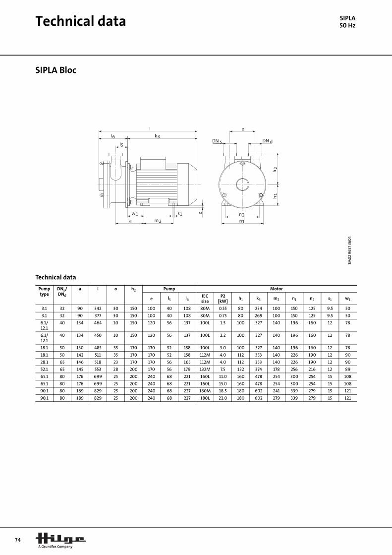
74
Technical data
SIPLA50 HzSIPLA Bloc
Technical data
TM0
2 9
657
36
04
Pump type
DNs/DNd
a l o h2 Pump Motor
e l5 l6IEC size
P2 [kW]
h1 k3 m2 n1 n2 s1 w1
3.1 32 90 342 30 150 100 40 108 80M 0.55 80 234 100 150 125 9.5 50
3.1 32 90 377 30 150 100 40 108 80M 0.75 80 269 100 150 125 9.5 50
6.1/12.1
40 134 464 10 150 120 56 137 100L 1.5 100 327 140 196 160 12 78
6.1/12.1
40 134 450 10 150 120 56 137 100L 2.2 100 327 140 196 160 12 78
18.1 50 130 485 35 170 170 52 158 100L 3.0 100 327 140 196 160 12 78
18.1 50 142 511 35 170 170 52 158 112M 4.0 112 353 140 226 190 12 90
28.1 65 146 518 23 170 170 56 165 112M 4.0 112 353 140 226 190 12 90
52.1 65 145 553 28 200 170 56 179 132M 7.5 132 374 178 256 216 12 89
65.1 80 176 699 25 200 240 68 221 160L 11.0 160 478 254 300 254 15 108
65.1 80 176 699 25 200 240 68 221 160L 15.0 160 478 254 300 254 15 108
90.1 80 189 829 25 200 240 68 227 180M 18.5 180 602 241 339 279 15 121
90.1 80 189 829 25 200 240 68 227 180L 22.0 180 602 279 339 279 15 121

Technical data
SIPLA50 HzSIPLA Bloc-SUPER on stainless steel ball feet
Technical data
TM0
2 9
658
36
04
Pump type
DNs/DNd
h1 h2 l n m Pump Motor Shroud
e l6' a c IEC size P2 [kW] p k3'
3.1 32 155 150 508 200 220 100 98 0 67 80M 0.55 224 410
3.1 32 155 150 508 200 220 100 98 0 67 80M 0.75 224 410
6.1/12.1 40 200 150 608 220 255 120 128 7 74 100L 1.5 274 480
6.1/12.1 40 200 150 608 220 255 120 128 7 74 100L 2.2 274 480
18.1 50 200 170 628 225 280 170 148 23 83 100L 3.0 274 480
18.1 50 200 170 628 225 280 170 148 23 83 112M 4.0 274 480
28.1 65 200 170 634 225 280 170 154 22 87 112M 4.0 274 480
52.1 65 200 200 768 225 300 170 168 23 100 132M 7.5 324 600
65.1 80 200 200 858 225 400 240 208 24 129 160L 11.0 374 650
65.1 80 200 200 858 225 400 240 208 24 129 160L 15.0 374 650
90.1 80 200 200 864 225 400 240 214 21 138 180M 18.5 374 650
90.1 80 200 200 864 225 400 240 214 21 138 180L 22.0 374 650
75
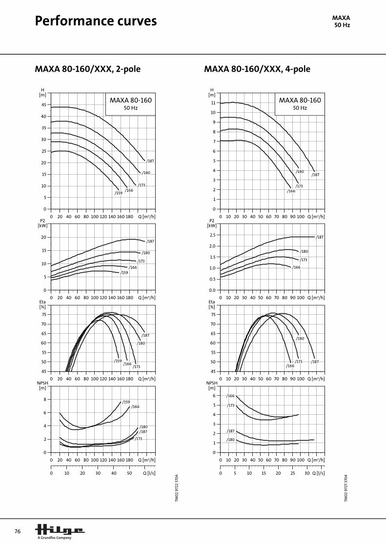
76
Performance curves
MAXA50 HzMAXA 80-160/XXX, 2-pole MAXA 80-160/XXX, 4-pole
TM0
2 9
722
370
4MA
XA
0 20 40 60 80 100 120 140 160 180 Q [m³/h]
0
5
10
15
20
25
30
35
40
45
H[m]
MAXA 80-16050 Hz
/159/166
/173
/180
/187
0 20 40 60 80 100 120 140 160 180 Q [m³/h]
0
5
10
15
20
P2[kW]
/159/166
/173
/180
/187
0 20 40 60 80 100 120 140 160 180 Q [m³/h]
45
50
55
60
65
70
75
[%]Eta
/159/166
/173
/180
/187
0 20 40 60 80 100 120 140 160 180 Q [m³/h]
0
2
4
6
8
[m]NPSH
0 10 20 30 40 50 Q [l/s]
/159/166
/173
/180/187
TM0
2 9
727
370
4
0 10 20 30 40 50 60 70 80 90 100 Q [m³/h]
0
1
2
3
4
5
6
7
8
9
10
11
H[m]
MAXA 80-16050 Hz
/166/173
/180/187
0 10 20 30 40 50 60 70 80 90 100 Q [m³/h]
0.0
0.5
1.0
1.5
2.0
2.5
P2[kW]
/166
/173
/180
/187
0 10 20 30 40 50 60 70 80 90 100 Q [m³/h]
45
50
55
60
65
70
75
[%]Eta
/166/173
/180
/187
0 10 20 30 40 50 60 70 80 90 100 Q [m³/h]
0
1
2
3
4
5
6
[m]NPSH
0 5 10 15 20 25 30 Q [l/s]
/187
/180
/173
/166
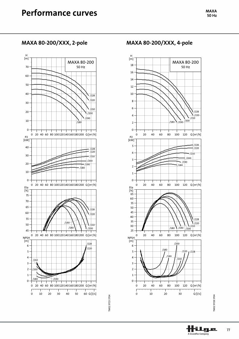
Performance curves
MAXA50 HzMAXA 80-200/XXX, 2-pole MAXA 80-200/XXX, 4-pole
TM0
2 9
723
370
4
0 20 40 60 80 100 120 140 160 180 200 Q [m³/h]
0
10
20
30
40
50
60
70
H[m]
MAXA 80-20050 Hz
/180
/190
/200
/210
/220
/228
0 20 40 60 80 100 120 140 160 180 200 Q [m³/h]
0
10
20
30
40
P2[kW]
/180/190
/200
/210
/220/228
0 20 40 60 80 100 120 140 160 180 200 Q [m³/h]
45
50
55
60
65
70
75
[%]Eta
/180
/190
/200
/210
/220
/228
0 20 40 60 80 100 120 140 160 180 200 Q [m³/h]
0
1
2
3
4
5
6
[m]NPSH
0 10 20 30 40 50 60 Q [l/s]
/180 /190
/200
/210
/220
/228
TM0
2 9
728
370
4
0 20 40 60 80 100 120 Q [m³/h]
0
2
4
6
8
10
12
14
16
18
H[m]
MAXA 80-20050 Hz
/180 /190/200
/210/220
/228
0 20 40 60 80 100 120 Q [m³/h]
0
1
2
3
4
5
P2[kW]
/180/190
/200
/210
/220/228
0 20 40 60 80 100 120 Q [m³/h]
25
30
35
40
45
50
55
60
65[%]Eta
/180 /190 /200/210
/220
/228
0 20 40 60 80 100 120 Q [m³/h]
0
1
2
3
4
5
6
[m]NPSH
0 10 20 30 Q [l/s]
/180
/190
/200
/210
/220 /228
77

78
Performance curves
MAXA50 HzMAXA 80-250/XXX, 2-pole MAXA 80-250/XXX, 4-pole
TM0
2 9
724
370
4
0 20 40 60 80 100 120 140 160 180 200 Q [m³/h]
20
30
40
50
60
70
80
90
100
110
H[m]
MAXA 80-25050 Hz
/220/230
/240
/250
/260/268
0 20 40 60 80 100 120 140 160 180 200 Q [m³/h]
10
20
30
40
50
60
P2[kW]
/220
/230/240
/250
/260
/268
0 20 40 60 80 100 120 140 160 180 200 Q [m³/h]
45
50
55
60
65
70
75
[%]Eta
/220
/230/240/250/260
/268
0 20 40 60 80 100 120 140 160 180 200 Q [m³/h]
0
2
4
6
8
[m]NPSH
0 10 20 30 40 50 60 Q [l/s]
/220
/230
/240/250
/260
/268
TM0
2 9
729
370
4
0 20 40 60 80 100 120 Q [m³/h]
0
2
4
6
8
10
12
14
16
18
20
22
24
26
H[m]
MAXA 80-25050 Hz
/220
/230
/240
/250
/260/268
0 20 40 60 80 100 120 Q [m³/h]
0
2
4
6
8
10
P2[kW]
/220/230/240/250/260/268
0 20 40 60 80 100 120 Q [m³/h]
45
50
55
60
65
70
75
[%]Eta
/220/230
/240/250
/260
/268
0 20 40 60 80 100 120 Q [m³/h]
0
1
2
3
4
5
6
[m]NPSH
0 10 20 30 Q [l/s]
/220/230/240/250/260/268
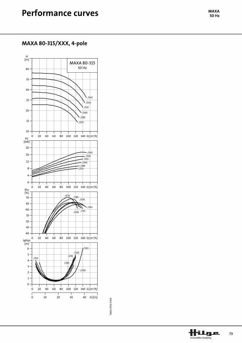
Performance curves
MAXA50 HzMAXA 80-315/XXX, 4-pole
TM0
2 9
730
370
4
0 20 40 60 80 100 120 140 Q [m³/h]
10
15
20
25
30
35
40
H[m]
MAXA 80-31550 Hz
/270
/285
/300
/315
/330
/343
0 20 40 60 80 100 120 140 Q [m³/h]
0
4
8
12
16
20
P2[kW]
/270/285
/300/315
/330/343
0 20 40 60 80 100 120 140 Q [m³/h]
40
45
50
55
60
65
70
[%]Eta
/270 /285
/300 /315
/330
/343
0 20 40 60 80 100 120 140 Q [m³/h]
0
1
2
3
4
5
6
[m]NPSH
0 10 20 30 40 Q [l/s]
/270
/285
/300
/315
/330
/343
79

80
Performance curves
MAXA50 HzMAXA 100-200/XXX, 2-pole MAXA 100-200/XXX, 4-pole
TM0
2 9
725
370
4
0 40 80 120 160 200 240 280 320 Q [m³/h]
0
10
20
30
40
50
60
70
H[m]
MAXA 100-20050 Hz
/185
/195 /205/215
/225
/234
0 40 80 120 160 200 240 280 320 Q [m³/h]
0
10
20
30
40
50
P2[kW]
/185/195
/205/215
/225
/234
0 40 80 120 160 200 240 280 320 Q [m³/h]
50
55
60
65
70
75
80
[%]Eta
/185
/195
/205
/215/225
/234
0 40 80 120 160 200 240 280 320 Q [m³/h]
0
1
2
3
4
5
6
[m]NPSH
0 20 40 60 80 Q [l/s]
/185
/195 /205
/215
/225
/234
TM0
2 9
731
370
4
0 20 40 60 80 100 120 140 Q [m³/h]
0
2
4
6
8
10
12
14
16
18
H[m]
MAXA 100-20050 Hz
/185 /195/205
/215
/225
/234
0 20 40 60 80 100 120 140 Q [m³/h]
0
1
2
3
4
5
6
P2[kW]
/185/195
/205
/215
/225
/234
0 20 40 60 80 100 120 140 Q [m³/h]
45
50
55
60
65
70
75
80
[%]Eta
/185
/195/205
/215
/225
/234
0 20 40 60 80 100 120 140 Q [m³/h]
0
1
2
3
4
5
6
[m]NPSH
0 10 20 30 40 Q [l/s]
/185
/195
/205
/215 /225/234

Performance curves
MAXA50 HzMAXA 100-250/XXX, 2-pole MAXA 100-250/XXX, 4-pole
TM0
2 9
726
370
4
0 40 80 120 160 200 240 280 Q [m³/h]
0
10
20
30
40
50
60
70
80
90
100
H[m]
MAXA 100-25050 Hz
/215
/225
/235
/245
/255
/267
0 40 80 120 160 200 240 280 Q [m³/h]
0
20
40
60
80
P2[kW]
/215/225/235/245
/255
/267
0 40 80 120 160 200 240 280 Q [m³/h]
50
55
60
65
70
75
80
[%]Eta
/215
/225
/235
/245
/255/267
0 40 80 120 160 200 240 280 Q [m³/h]
0
1
2
3
4
5
[m]NPSH
0 20 40 60 80 Q [l/s]
/215
/225
/235
/245
/255
/267
TM0
2 9
732
370
4
0 20 40 60 80 100 120 140 160 Q [m³/h]
0
2
4
6
8
10
12
14
16
18
20
22
24
26
H[m]
MAXA 100-25050 Hz
/215
/225
/235
/245
/255
/267
0 20 40 60 80 100 120 140 160 Q [m³/h]
0
2
4
6
8
10
P2[kW]
/215/225/235/245/255
/267
0 20 40 60 80 100 120 140 160 Q [m³/h]
45
50
55
60
65
70
75
80
[%]Eta
/215
/225
/235/245
/255
/267
0 20 40 60 80 100 120 140 160 Q [m³/h]
0
1
2
3
4
5
6
[m]NPSH
0 10 20 30 40 50 Q [l/s]
/215/225
/235 /245/255
/267
81

82
Performance curves
MAXA50 HzMAXA 125-250/XXX, 4-pole MAXA 125-315/XXX, 4-pole
TM0
2 9
733
370
4
0 40 80 120 160 200 240 Q [m³/h]
0
2
4
6
8
10
12
14
16
18
20
22
24
26
28
H[m]
MAXA 125-25050 Hz
/220 /230/245
/260
/275
/290
0 40 80 120 160 200 240 Q [m³/h]
0
4
8
12
16
P2[kW]
/220/230
/245
/260
/275
/290
0 40 80 120 160 200 240 Q [m³/h]
40
45
50
55
60
65
70
75
[%]Eta
/220
/230
/245
/260
/275/290
0 40 80 120 160 200 240 Q [m³/h]
0
1
2
3
4
5
[m]NPSH
0 20 40 60 Q [l/s]
/220 /230
/245 /260
/275
/290
TM0
2 9
734
370
4
0 40 80 120 160 200 240 Q [m³/h]
0
5
10
15
20
25
30
35
40
45
H[m]
MAXA 125-31550 Hz
/295
/310
/325
/340
/353
0 40 80 120 160 200 240 Q [m³/h]
0
10
20
30
40
P2[kW]
/295/310/325
/340
/353
0 40 80 120 160 200 240 Q [m³/h]
45
50
55
60
65
70
75
80
[%]Eta
/295
/310/325
/340/353
0 40 80 120 160 200 240 Q [m³/h]
0
1
2
3
4
5
6
7
[m]NPSH
0 20 40 60 Q [l/s]
/295/310/325
/340
/353
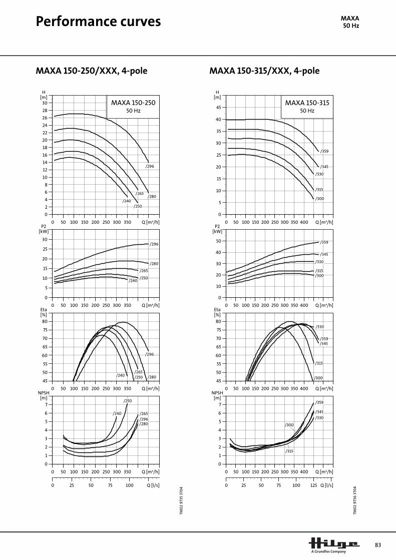
Performance curves
MAXA50 HzMAXA 150-250/XXX, 4-pole MAXA 150-315/XXX, 4-pole
TM0
2 9
735
370
4
0 50 100 150 200 250 300 350 Q [m³/h]
0
2
4
6
8
10
12
14
16
18
20
22
24
26
28
30
H[m]
MAXA 150-25050 Hz
/240/250
/265/280
/296
0 50 100 150 200 250 300 350 Q [m³/h]
0
5
10
15
20
25
30
P2[kW]
/240/250
/265
/280
/296
0 50 100 150 200 250 300 350 Q [m³/h]
45
50
55
60
65
70
75
80
[%]Eta
/240 /250/265
/280
/296
0 50 100 150 200 250 300 350 Q [m³/h]
0
1
2
3
4
5
6
7
[m]NPSH
0 25 50 75 100 Q [l/s]
/240
/250
/265
/280/296
TM0
2 9
736
370
4
0 50 100 150 200 250 300 350 400 Q [m³/h]
0
5
10
15
20
25
30
35
40
45
H[m]
MAXA 150-31550 Hz
/300
/315
/330
/345
/359
0 50 100 150 200 250 300 350 400 Q [m³/h]
0
10
20
30
40
50
P2[kW]
/300/315
/330
/345
/359
0 50 100 150 200 250 300 350 400 Q [m³/h]
45
50
55
60
65
70
75
80
[%]Eta
/300
/315
/330
/345/359
0 50 100 150 200 250 300 350 400 Q [m³/h]
0
1
2
3
4
5
6
7
[m]NPSH
0 25 50 75 100 125 Q [l/s]
/300
/315
/330
/345
/359
83

84
Performance curves
MAXA50 HzMAXA 150-400/XXX, 4-pole MAXA 200-400/XXX, 4-pole
TM0
2 9
737
370
4
0 50 100 150 200 250 300 350 400 Q [m³/h]
10
15
20
25
30
35
40
45
50
55
60
65
70
H[m]
MAXA 150-40050 Hz
/340
/360
/380
/400
/420
/435
0 50 100 150 200 250 300 350 400 Q [m³/h]
0
20
40
60
80
100
P2[kW]
/340/360
/380
/400
/420/435
0 50 100 150 200 250 300 350 400 Q [m³/h]
40
45
50
55
60
65
70
75
[%]Eta
/340
/360
/380/400
/420
/435
0 50 100 150 200 250 300 350 400 Q [m³/h]
0
1
2
3
4
5
6
[m]NPSH
0 25 50 75 100 125 Q [l/s]
/340 /360
/380/400
/420/435
TM0
2 9
738
370
4
0 100 200 300 400 500 600 700 800Q [m³/h]
0
5
10
15
20
25
30
35
40
45
50
55
H[m]
MAXA 200-40050 Hz
/345
/370
/408
/420
0 100 200 300 400 500 600 700 800Q [m³/h]
20
30
40
50
60
70
80
P2[kW]
/345
/370
/408
/420
0 100 200 300 400 500 600 700 800Q [m³/h]
50
55
60
65
70
75
80
85
[%]Eta
/345
/370
/408
/420
0 100 200 300 400 500 600 700 800Q [m³/h]
3
4
5
6
7
8
9
[m]NPSH
0 50 100 150 200 Q [l/s]
/345
/370/420

Technical data
MAXA L50 HzMAXA L
Technical data, 2-pole
TM0
2 9
653
36
04
Pumpsize
P2 [kW]
IEC size k3
(1) a1 f3 h2 p3 p4 p5 DNs(2) DNd
(2) p6 u(1) w1 h1 m1 m2 n1 n2 h9 s1
Net weight
[kg]
80-160
11.0 160M 490 125 218 225 150 157 185
100(125,150)
80(100)
350 240 108 160 210 256 300 254 18 15 118
15.0 160M 490 125 218 225 150 157 185 350 240 108 160 210 256 300 254 18 15 131
18.5 160L 530 125 218 225 150 157 185 350 240 108 160 254 300 300 254 18 15 148
22.0 180M 605 125 218 225 150 157 185 350 265 121 180 241 287 339 279 18 15 164
80-200
15.0 160M 490 125 220 250 170 171 205 350 240 108 160 210 256 300 254 18 15 166
18.5 160L 530 125 220 250 170 171 205 350 240 108 160 254 300 300 254 18 15 183
22.0 180M 605 125 220 250 170 171 205 350 265 121 180 241 287 339 279 18 15 199
30.0 200L 665 125 220 250 170 171 205 400 310 133 200 305 355 388 318 24 19 249
37.0 200L 665 125 220 250 170 171 205 400 310 133 200 305 355 388 318 24 19 272
80-25030.0 200L 665 125 220 280 180 189 220 400 310 133 200 305 355 388 318 24 19 264
37.0 200L 665 125 220 280 180 189 220 400 310 133 200 305 355 388 318 24 19 287
100-200
18.5 160L 530 125 220 280 170 171 205
125(150)
100(125)
350 240 108 160 254 300 300 254 18 15 196
22.0 180M 605 125 220 280 170 171 205 350 265 121 180 241 287 339 279 18 15 212
30.0 200L 665 125 220 280 170 171 205 400 310 133 200 305 355 388 318 24 19 262
37.0 200L 665 125 220 280 170 171 205 400 310 133 200 305 355 388 318 24 19 285
(1) Motor dimensions depend on make, max. size for basic design given.
(2) Flange dimensions are according to DIN EN 1092-1 (DIN 2632). Nominal diameter in parenthesis are available on request.
85

86
Technical data
MAXA L50 HzTechnical data, 4-pole
TM0
3 0
142
410
4
★ This sketch applies to pump size 80-160 onlyFor pump sizes 80-200 to 125-250, see previous page.
Pumpsize
P2 [kW]
IEC size k3
(1) a1 f3 h2 p3 p4 p5 DNs(2) DNd
(2) p6 u(1) w1 h1 m1 m2 n1 n2 h9 s1
Net weight
[kg]
80-160★3.0 100L 320 125 168.5 225 150 157 185
100(125,150)
80(100)
250 175 52 180 - - - - - - 77
4.0 112M 340 125 168.5 225 150 157 185 250 185 52 180 - - - - - - 82
80-2005.5 132S 390 125 200 250 170 171 205 300 205 89 132 140 180 256 216 15 12 116
7.5 132M 420 125 200 250 170 171 205 300 205 89 132 178 218 256 216 15 12 129
80-250
5.5 132S 390 125 200 280 180 189 220 300 205 89 132 140 180 256 216 15 12 123
7.5 132M 420 125 200 280 180 189 220 300 205 89 132 178 218 256 216 15 12 136
11.0 160M 490 125 220 280 180 189 220 350 240 108 160 210 256 300 254 18 15 163
80-315
5.5 132S 390 125 200 315 208 215 225 300 205 89 132 140 180 256 216 15 12 136
7.5 132M 420 125 200 315 208 215 225 300 205 89 132 178 218 256 216 15 12 149
11.0 160M 490 125 220 315 208 215 225 350 240 108 160 210 256 300 254 18 15 176
15.0 160L 530 125 220 315 208 215 225 350 240 108 160 254 300 300 254 18 15 193
18.5 180M 605 125 220 315 208 215 225 350 265 121 180 241 287 339 279 18 15 267
22.0 180L 605 125 220 315 208 215 225 350 265 121 180 279 325 339 279 18 15 282
100-2005.5 132S 390 125 200 280 170 171 205
125(150)
100(125)
300 205 89 132 140 180 256 216 15 12 123
7.5 132M 420 125 200 280 170 171 205 300 205 89 132 178 218 256 216 15 12 136
100-250
5.5 132S 390 140 200 280 180 189 220 300 205 89 132 140 180 256 216 15 12 131
7.5 132M 420 140 200 280 180 189 220 300 205 89 132 178 218 256 216 15 12 144
11.0 160M 490 140 220 280 180 189 220 350 240 108 160 210 256 300 254 18 15 171
15.0 160L 530 140 220 280 180 189 220 350 240 108 160 254 300 300 254 18 15 188
100-315
7.5 132M 420 140 200 315 208 215 255 300 205 89 132 178 218 256 216 15 12 166
11.0 160M 490 140 220 315 208 215 255 350 240 108 160 210 256 300 254 18 15 193
15.0 160L 530 140 220 315 208 215 255 350 240 108 160 254 300 300 254 18 15 210
18.5 180M 605 140 220 315 208 215 255 350 265 121 180 241 287 339 279 18 15 284
22.0 180L 605 140 220 315 208 215 255 350 265 121 180 279 325 339 279 18 15 299
30.0 200L 665 140 220 315 208 215 255 400 310 133 200 305 355 388 318 24 19 366
125-250
7.5 132M 420 140 200 355 200 206 260
150(200)
125(150)
300 205 89 132 178 218 256 216 15 12 160
11.0 160M 490 140 220 355 200 206 260 350 240 108 160 210 256 300 254 18 15 187
15.0 160L 530 140 220 355 200 206 260 350 240 108 160 254 300 300 254 18 15 204
18.5 180M 605 140 220 355 200 206 260 350 265 121 180 241 287 339 279 18 15 278
22.0 180L 605 140 220 355 200 206 260 350 265 121 180 279 325 339 279 18 15 293
(1) Motor dimensions depend on make, max. size for basic design given.
(2) Flange dimensions are according to DIN EN 1092-1 (DIN 2632).
(3) Nominal diameter in parenthesis are available on request.
(6) Pumps fitted with motors of IEC size 100 and 112 are supported with pump foot and motor foot; from IEC size 132 pumps are fitted with motor foot only.

Technical data
MAXA CN50 HzMAXA CN
Technical data, 2-pole
TM0
2 9
654
36
04
Pumpsize
P2 [kW]
IEC size k3
(1) l5 E(7) f1 a1 h1 h2 h7 Ø d Ø d4 DNs(2) DNd
(2) a2 l1 l2 l3 b1 b2 b3 d5Baseplate
size
Net weight
[kg]
80-160
11.0 160M 600 559 74 360 125 180 225 290 24 42
100(125,150)
80(100)
75 1250 205 840 480 590 540 24 6 212
15.0 160M 600 559 74 360 125 180 225 290 24 42 75 1250 205 840 480 590 540 24 6 225
18.5 160L 640 559 74 360 125 180 225 290 24 42 75 1250 205 840 480 590 540 24 6 240
22.0 180M 715 665 80 360 125 180 225 290 24 48 75 1250 205 840 480 590 540 24 6 255
30.0 200L 775 573 88 360 125 180 225 310 24 55 75 1250 205 840 480 590 540 24 6 305
80-200
15.0 160M 600 669 74 470 125 180 250 290 32 42 75 1250 205 840 480 590 540 24 6 235
18.5 160L 640 669 74 470 125 180 250 290 32 42 75 1250 205 840 480 590 540 24 6 250
22.0 180M 715 676 80 470 125 180 250 290 32 48 75 1250 205 840 480 590 540 24 6 265
30.0 200L 775 683 88 470 125 180 250 310 32 55 75 1250 205 840 480 590 540 24 6 315
37.0 200L 775 683 88 470 125 180 250 310 32 55 75 1250 205 840 480 590 540 24 6 338
45.0 225M 840 683 88 470 125 180 250 365 32 55 75 1600 270 1060 580 710 650 28 7 542
80-250
30.0 200L 775 683 88 470 125 200 280 310 32 55 90 1250 205 840 480 590 540 24 6 330
37.0 200L 775 683 88 470 125 200 280 310 32 55 90 1250 205 840 480 590 540 24 6 353
45.0 225M 840 683 88 470 125 200 280 365 32 55 90 1600 270 1060 580 710 650 28 7 557
55.0 250M 930 697 102 470 125 200 280 390 32 60 90 1600 270 1060 580 710 650 28 7 662
75.0 280S 1040 697 102 470 125 200 280 420 32 65 90 1800 300 1200 650 780 720 28 8 861
90.0 280M 1040 697 102 470 125 200 280 420 32 65 90 1800 300 1200 650 780 720 28 8 901
100-200
18.5 160L 640 669 74 470 125 200 280 310 32 42
125(150)
100(125)
90 1250 205 840 480 590 540 24 6 263
22.0 180M 715 676 80 470 125 200 280 310 32 48 90 1250 205 840 480 590 540 24 6 278
30.0 200L 775 683 88 470 125 200 280 310 32 55 90 1250 205 840 480 590 540 24 6 328
37.0 200L 775 683 88 470 125 200 280 310 32 55 90 1250 205 840 480 590 540 24 6 351
45.0 225M 840 683 88 470 125 200 280 365 32 55 90 1600 270 1060 580 710 650 28 7 555
55.0 250M 930 697 102 470 125 200 280 390 32 60 90 1600 270 1060 580 710 650 28 7 660
75.0 280S 1040 697 102 470 125 200 280 420 32 65 90 1800 300 1200 650 780 720 28 8 859
100-250
30.0 200L 775 698 88 470 140 225 280 335 32 55 90 1250 205 840 480 590 540 24 6 339
37.0 200L 775 698 88 470 140 225 280 335 32 55 90 1250 205 840 480 590 540 24 6 362
45.0 225M 840 698 88 470 140 225 280 365 32 55 90 1600 270 1060 580 710 650 28 7 566
55.0 250M 930 712 102 470 140 225 280 390 32 60 90 1600 270 1060 580 710 650 28 7 671
75.0 280S 1040 712 102 470 140 225 280 420 32 65 90 1800 300 1200 650 780 720 28 8 870
90.0 280M 1040 712 102 470 140 225 280 420 32 65 90 1800 300 1200 650 780 720 28 8 910
87
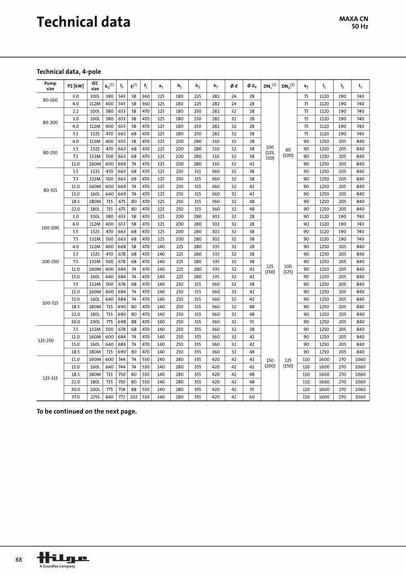
88
Technical data
MAXA CN50 HzTechnical data, 4-pole
To be continued on the next page.
Pumpsize
P2 [kW]IEC size k3
(1) l5 E(7) f1 a1 h1 h2 h7 Ø d Ø d4 DNs(2) DNd
(2) a2 l1 l2 l3
80-1603.0 100L 380 543 58 360 125 180 225 282 24 28
100(125,150)
80(100)
75 1120 190 740
4.0 112M 400 543 58 360 125 180 225 282 24 28 75 1120 190 740
80-200
2.2 100L 380 653 58 470 125 180 250 282 32 28 75 1120 190 740
3.0 100L 380 653 58 470 125 180 250 282 32 28 75 1120 190 740
4.0 112M 400 653 58 470 125 180 250 282 32 28 75 1120 190 740
5.5 132S 470 663 68 470 125 180 250 282 32 38 75 1120 190 740
80-250
4.0 112M 400 653 58 470 125 200 280 310 32 28 90 1250 205 840
5.5 132S 470 663 68 470 125 200 280 310 32 38 90 1250 205 840
7.5 132M 500 663 68 470 125 200 280 310 32 38 90 1250 205 840
11.0 160M 600 669 74 470 125 200 280 310 32 42 90 1250 205 840
80-315
5.5 132S 470 663 68 470 125 250 315 360 32 38 90 1250 205 840
7.5 132M 500 663 68 470 125 250 315 360 32 38 90 1250 205 840
11.0 160M 600 669 74 470 125 250 315 360 32 42 90 1250 205 840
15.0 160L 640 669 74 470 125 250 315 360 32 42 90 1250 205 840
18.5 180M 715 675 80 470 125 250 315 360 32 48 90 1250 205 840
22.0 180L 715 675 80 470 125 250 315 360 32 48 90 1250 205 840
100-200
3.0 100L 380 653 58 470 125 200 280 302 32 28
125(150)
100(125)
90 1120 190 740
4.0 112M 400 653 58 470 125 200 280 302 32 28 90 1120 190 740
5.5 132S 470 663 68 470 125 200 280 302 32 38 90 1120 190 740
7.5 132M 500 663 68 470 125 200 280 302 32 38 90 1120 190 740
100-250
4.0 112M 400 668 58 470 140 225 280 335 32 28 90 1250 205 840
5.5 132S 470 678 68 470 140 225 280 335 32 38 90 1250 205 840
7.5 132M 500 678 68 470 140 225 280 335 32 38 90 1250 205 840
11.0 160M 600 684 74 470 140 225 280 335 32 42 90 1250 205 840
15.0 160L 640 684 74 470 140 225 280 335 32 42 90 1250 205 840
100-315
7.5 132M 500 678 68 470 140 250 315 360 32 38 90 1250 205 840
11.0 160M 600 684 74 470 140 250 315 360 32 42 90 1250 205 840
15.0 160L 640 684 74 470 140 250 315 360 32 42 90 1250 205 840
18.5 180M 715 690 80 470 140 250 315 360 32 48 90 1250 205 840
22.0 180L 715 690 80 470 140 250 315 360 32 48 90 1250 205 840
30.0 200L 775 698 88 470 140 250 315 360 32 55 90 1250 205 840
125-250
7.5 132M 500 678 68 470 140 250 355 360 32 38
150(200)
125(150)
90 1250 205 840
11.0 160M 600 684 74 470 140 250 355 360 32 42 90 1250 205 840
15.0 160L 640 684 74 470 140 250 355 360 32 42 90 1250 205 840
18.5 180M 715 690 80 470 140 250 355 360 32 48 90 1250 205 840
125-315
11.0 160M 600 744 74 530 140 280 355 420 42 42 110 1600 270 1060
15.0 160L 640 744 74 530 140 280 355 420 42 42 110 1600 270 1060
18.5 180M 715 750 80 530 140 280 355 420 42 48 110 1600 270 1060
22.0 180L 715 750 80 530 140 280 355 420 42 48 110 1600 270 1060
30.0 200L 775 758 88 530 140 280 355 420 42 55 110 1600 270 1060
37.0 225S 840 772 102 530 140 280 355 420 42 60 110 1600 270 1060

Technical data
MAXA CN50 HzContinued from previous page.
Pumpsize
P2 [kW]IEC size k3
(1) l5 E(7) f1 a1 h1 h2 h7 Ø d Ø d4 DNs(2) DNd
(2) a2 l1 l2 l3
150-250
11.0 160M 600 764 74 530 160 280 375 420 42 42
200(250)
150
110 1600 270 1060
15.0 160L 640 764 74 530 160 280 375 420 42 42 110 1600 270 1060
18.5 180M 715 770 80 530 160 280 375 420 42 48 110 1600 270 1060
22.0 180L 715 770 80 530 160 280 375 420 42 48 110 1600 270 1060
30.0 200L 775 778 88 530 160 280 375 420 42 55 110 1600 270 1060
150-315
15.0 160L 640 764 74 530 160 280 400 420 42 42 110 1800 300 1200
18.5 180M 715 770 80 530 160 280 400 420 42 48 110 1800 300 1200
22.0 180L 715 770 80 530 160 280 400 420 42 48 110 1800 300 1200
30.0 200L 775 778 88 530 160 280 400 420 42 55 110 1800 300 1200
37.0 225S 840 792 102 530 160 280 400 420 42 60 110 1800 300 1200
45.0 225M 840 792 102 530 160 280 400 420 42 60 110 1800 300 1200
55.0 250M 930 792 102 530 160 280 400 420 42 65 110 1800 300 1200
150-400
30.0 200L 775 778 88 530 160 315 450 455 42 55 110 1800 300 1200
37.0 225S 840 792 102 530 160 315 450 455 42 60 110 1800 300 1200
45.0 225M 840 792 102 530 160 315 450 455 42 60 110 1800 300 1200
55.0 250M 930 792 102 530 160 315 450 455 42 65 110 1800 300 1200
75.0 280S 1040 806 116 530 160 315 450 455 42 75 110 1800 300 1200
90.0 280M 1040 806 116 530 160 315 450 455 42 75 110 1800 300 1200
200-400
30.0 200L 775 814 88 551 175 315 530 455 42 55
200
110 1800 300 1200
37.0 225S 840 828 102 551 175 315 530 455 42 60 110 1800 300 1200
45.0 225M 840 828 102 551 175 315 530 455 42 60 110 1800 300 1200
55.0 250M 930 828 102 551 175 315 530 455 42 65 110 1800 300 1200
75.0 280S 1040 842 116 551 175 315 530 455 42 75 110 1800 300 1200
90.0 280M 1040 842 116 551 175 315 530 455 42 75 110 1800 300 1200
(1) Motor dimensions depend on make, max. size for basic design given.
(2) Flange dimensions are according to DIN EN 1092-1 (DIN 2632).
(3) Nominal diameter in parenthesis are available on request.
(7) Coupling of our choice.
Larger motors, threaded pipework connections and special flanges are available on request.
89
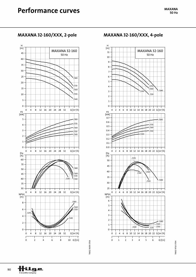
90
Performance curves
MAXANA50 HzMAXANA 32-160/XXX, 2-pole MAXANA 32-160/XXX, 4-pole
TM0
2 9
69
9 3
704M
AX
AN
A
0 4 8 12 16 20 24 28 32 Q [m³/h]
0
5
10
15
20
25
30
35
40
45
H[m]
MAXANA 32-16050 Hz
/140
/150
/160
/170
/180
0 4 8 12 16 20 24 28 32 Q [m³/h]
0
1
2
3
4
5
P2[kW]
/140
/150
/160
/170
/180
0 4 8 12 16 20 24 28 32 Q [m³/h]
30
35
40
45
50
55
60
[%]Eta
/140 /150
/160/170
/180
0 4 8 12 16 20 24 28 32 Q [m³/h]
0
2
4
6
8
[m]NPSH
0 2 4 6 8 10 Q [l/s]
/140
/150/160
/170
/180
TM0
2 9
710
370
4
0 2 4 6 8 10 12 14 16 18 20 22 Q [m³/h]
0
1
2
3
4
5
6
7
8
9
10
11
H[m]
MAXANA 32-16050 Hz
/140
/150
/160/170
/180
0 2 4 6 8 10 12 14 16 18 20 22 Q [m³/h]
0.0
0.1
0.2
0.3
0.4
0.5
0.6
0.7
P2[kW]
/140
/150
/160/170
/180
0 2 4 6 8 10 12 14 16 18 20 22 Q [m³/h]
25
30
35
40
45
50
[%]Eta
/140
/150
/160
/170
/180
0 2 4 6 8 10 12 14 16 18 20 22 Q [m³/h]
0
1
2
3
4
5
6
[m]NPSH
0 1 2 3 4 5 6 Q [l/s]
/140 /150/160
/170
/180

Performance curves
MAXANA50 HzMAXANA 32-200/XXX, 2-pole MAXANA 32-200/XXX, 4-pole
TM0
2 9
700
370
4
0 5 10 15 20 25 30 35 40 Q [m³/h]
0
10
20
30
40
50
60
70
H[m]
MAXANA 32-20050 Hz
/170
/180
/190
/200
/210
/220
0 5 10 15 20 25 30 35 40 Q [m³/h]
0
2
4
6
8
10
12
P2[kW]
/170
/180
/190
/200/210/220
0 5 10 15 20 25 30 35 40 Q [m³/h]
30
35
40
45
50
55
[%]Eta
/170
/180
/190/200/210/220
0 5 10 15 20 25 30 35 40 Q [m³/h]
0
2
4
6
8
[m]NPSH
0 2 4 6 8 10 Q [l/s]
/170
/180
/190
/200
/210
/220
TM0
2 9
711
370
4
0 4 8 12 16 20 24 28 32 Q [m³/h]
2
4
6
8
10
12
14
16
H[m]
MAXANA 32-20050 Hz
/170 /180/190
/200
/210/220
0 4 8 12 16 20 24 28 32 Q [m³/h]
0.0
0.4
0.8
1.2
1.6
2.0
P2[kW]
/170/180
/190
/200
/210
/220
0 4 8 12 16 20 24 28 32 Q [m³/h]
25
30
35
40
45
50
55
[%]Eta
/170
/180
/190
/200/210
/220
0 4 8 12 16 20 24 28 32 Q [m³/h]
0
1
2
3
4
5
6
[m]NPSH
0 2 4 6 8 Q [l/s]
/180
/170
/190 /200
/210
/220
91
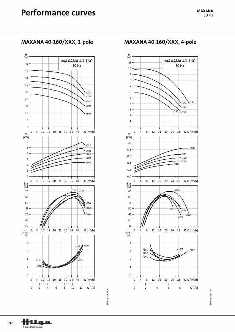
92
Performance curves
MAXANA50 HzMAXANA 40-160/XXX, 2-pole MAXANA 40-160/XXX, 4-pole
TM0
2 9
701
370
4
0 5 10 15 20 25 30 35 40 Q [m³/h]
0
5
10
15
20
25
30
35
40
45
H[m]
MAXANA 40-16050 Hz
/140
/150
/160
/170
/180
0 5 10 15 20 25 30 35 40 Q [m³/h]
0
1
2
3
4
5
6
P2[kW]
/140
/150
/160/170
/180
0 5 10 15 20 25 30 35 40 Q [m³/h]
40
45
50
55
60
65
70
[%]Eta
/140
/150 /160
/170
/180
0 5 10 15 20 25 30 35 40 Q [m³/h]
0
2
4
6
8
[m]NPSH
0 2 4 6 8 10 12 Q [l/s]
/140
/150
/160 /170
/180
TM0
2 9
712
370
4
0 4 8 12 16 20 24 28 32 Q [m³/h]
0
1
2
3
4
5
6
7
8
9
10
11
H[m]
MAXANA 40-16050 Hz
/140 /150
/160
/170 /180
0 4 8 12 16 20 24 28 32 Q [m³/h]
0.0
0.2
0.4
0.6
0.8
1.0
P2[kW]
/140/150/160
/170
/180
0 4 8 12 16 20 24 28 32 Q [m³/h]
35
40
45
50
55
60
65
[%]Eta
/140
/150
/160
/170
/180
0 4 8 12 16 20 24 28 32 Q [m³/h]
0
1
2
3
4
[m]NPSH
0 2 4 6 8 Q [l/s]
/180/170
/160/150
/140
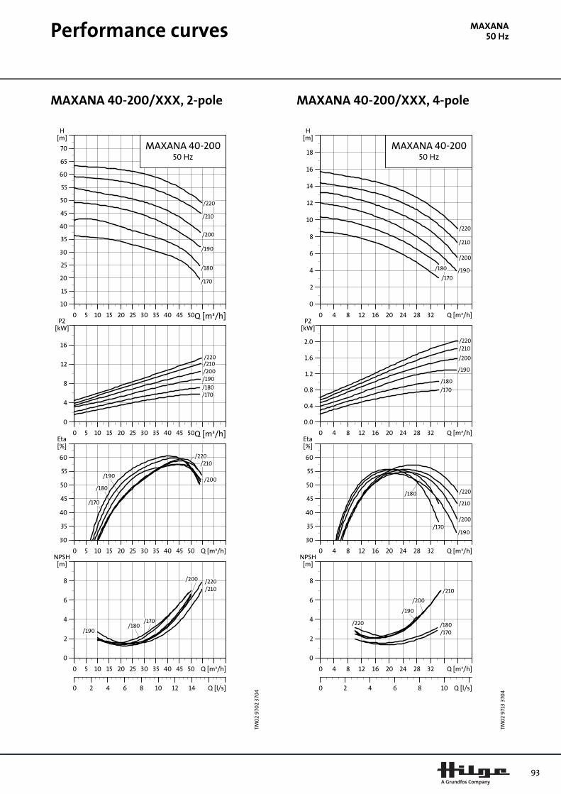
Performance curves
MAXANA50 HzMAXANA 40-200/XXX, 2-pole MAXANA 40-200/XXX, 4-pole
TM0
2 9
702
370
4
0 5 10 15 20 25 30 35 40 45 50Q [m³/h]
10
15
20
25
30
35
40
45
50
55
60
65
70
H[m]
MAXANA 40-20050 Hz
/170
/180
/190
/200
/210
/220
0 5 10 15 20 25 30 35 40 45 50Q [m³/h]
0
4
8
12
16
P2[kW]
/170/180
/190/200/210/220
0 5 10 15 20 25 30 35 40 45 50 Q [m³/h]
30
35
40
45
50
55
60
[%]Eta
/170
/180
/190/200
/210/220
0 5 10 15 20 25 30 35 40 45 50 Q [m³/h]
0
2
4
6
8
[m]NPSH
0 2 4 6 8 10 12 14 Q [l/s]
/170/180
/190
/200
/210/220
TM0
2 9
713
370
4
0 4 8 12 16 20 24 28 32 Q [m³/h]
0
2
4
6
8
10
12
14
16
18
H[m]
MAXANA 40-20050 Hz
/170
/180 /190
/200
/210
/220
0 4 8 12 16 20 24 28 32 Q [m³/h]
0.0
0.4
0.8
1.2
1.6
2.0
P2[kW]
/170
/180
/190
/200
/210/220
0 4 8 12 16 20 24 28 32 Q [m³/h]
30
35
40
45
50
55
60
[%]Eta
/170
/180
/190
/200
/210
/220
0 4 8 12 16 20 24 28 32 Q [m³/h]
0
2
4
6
8
[m]NPSH
0 2 4 6 8 10 Q [l/s]
/180/170
/190
/200
/210
/220
93

94
Performance curves
MAXANA50 HzMAXANA 50-125/XXX, 2-pole MAXANA 50-125/XXX, 4-pole
TM0
2 9
703
370
4
0 10 20 30 40 50 60 70 Q [m³/h]
0
5
10
15
20
25
30
H[m]
MAXANA 50-12550 Hz
/115
/125
/135
/145
0 10 20 30 40 50 60 70 Q [m³/h]
0
1
2
3
4
5
P2[kW]
/115
/125
/135
/145
0 10 20 30 40 50 60 70 Q [m³/h]
40
45
50
55
60
65
70
[%]Eta
/115/125
/135
/145
0 10 20 30 40 50 60 70 Q [m³/h]
0
2
4
6
8
[m]NPSH
0 5 10 15 20 Q [l/s]
/115
/125
/135
/145
TM0
2 9
714
370
4
0 5 10 15 20 25 30 35 40 Q [m³/h]
0
1
2
3
4
5
6
7
H[m]
MAXANA 50-12550 Hz
/115
/125
/135
/145
0 5 10 15 20 25 30 35 40 Q [m³/h]
0.0
0.1
0.2
0.3
0.4
0.5
0.6
0.7
P2[kW]
/115
/125
/135
/145
0 5 10 15 20 25 30 35 40 Q [m³/h]
25
30
35
40
45
50
55
60
[%]Eta
/115 /125
/135
/145
0 5 10 15 20 25 30 35 40 Q [m³/h]
1.2
1.4
1.6
1.8
2.0
2.2
2.4
[m]NPSH
0 2 4 6 8 10 Q [l/s]
/145/135
/125
/115

Performance curves
MAXANA50 HzMAXANA 50-160/XXX, 2-pole MAXANA 50-160/XXX, 4-pole
TM0
2 9
704
370
4
0 10 20 30 40 50 60 70 Q [m³/h]
0
5
10
15
20
25
30
35
40
45
50
H[m]
MAXANA 50-16050 Hz
/140
/150
/160
/170
/180
0 10 20 30 40 50 60 70 Q [m³/h]
0
2
4
6
8
10
P2[kW]
/140
/150/160
/170
/180
0 10 20 30 40 50 60 70 Q [m³/h]
40
45
50
55
60
65
70
[%]Eta
/140
/150
/160
/170
/180
0 10 20 30 40 50 60 70 Q [m³/h]
0
2
4
6
8
[m]NPSH
0 5 10 15 20 Q [l/s]
/140
/150/160
/170/180
TM0
2 9
715
370
4
0 5 10 15 20 25 30 35 40 45 Q [m³/h]
0
1
2
3
4
5
6
7
8
9
10
11
12
H[m]
MAXANA 50-16050 Hz
/140/150
/160/170
/180
0 5 10 15 20 25 30 35 40 45 Q [m³/h]
0.0
0.2
0.4
0.6
0.8
1.0
1.2
1.4
P2[kW]
/140
/150
/160
/170
/180
0 5 10 15 20 25 30 35 40 45 Q [m³/h]
35
40
45
50
55
60
65
70
[%]Eta
/140/150
/160
/170
/180
0 5 10 15 20 25 30 35 40 45 Q [m³/h]
0
1
2
3
4
5
[m]NPSH
0 2 4 6 8 10 12 14 Q [l/s]
/170
/160/150
/140
/180
95

96
Performance curves
MAXANA50 HzMAXANA 50-200/XXX, 2-pole MAXANA 50-200/XXX, 4-pole
TM0
2 9
705
370
4
0 10 20 30 40 50 60 70 80 Q [m³/h]
10
20
30
40
50
60
70
H[m]
MAXANA 50-20050 Hz
/170
/180
/190
/200
/210
/220
0 10 20 30 40 50 60 70 80 Q [m³/h]
0
4
8
12
16
20
P2[kW]
/170
/180/190/200/210/220
0 10 20 30 40 50 60 70 80 Q [m³/h]
40
45
50
55
60
65
70
[%]Eta
/170/180
/190/200
/210
/220
0 10 20 30 40 50 60 70 80 Q [m³/h]
0
2
4
6
8
[m]NPSH
0 5 10 15 20 Q [l/s]
/170
/180/190
/200
/210
/220
TM0
2 9
716
370
4
0 10 20 30 40 50 60 Q [m³/h]
0
2
4
6
8
10
12
14
16
18
H[m]
MAXANA 50-20050 Hz
/170 /180
/190/200
/210
/220
0 10 20 30 40 50 60 Q [m³/h]
0.0
0.5
1.0
1.5
2.0
2.5
3.0
P2[kW]
/170
/180
/190
/200
/210
/220
0 10 20 30 40 50 60 Q [m³/h]
35
40
45
50
55
60
65
[%]Eta
/170 /180
/190
/200
/210
/220
0 10 20 30 40 50 60 Q [m³/h]
0
2
4
6
8
[m]NPSH
0 5 10 15 Q [l/s]
/170
/180/190
/200
/210
/220

Performance curves
MAXANA50 HzMAXANA 65-125/XXX, 2-pole
TM0
2 9
706
370
4
0 20 40 60 80 100 120 Q [m³/h]
0
5
10
15
20
25
30
H[m]
MAXANA 65-12550 Hz
/155
0 20 40 60 80 100 120 Q [m³/h]
0
2
4
6
8
10
P2[kW]
/155
0 20 40 60 80 100 120 Q [m³/h]
30
35
40
45
50
55
60
[%]Eta
/155
0 20 40 60 80 100 120 Q [m³/h]
0
2
4
6
8
[m]NPSH
0 10 20 30 Q [l/s]
/155
97
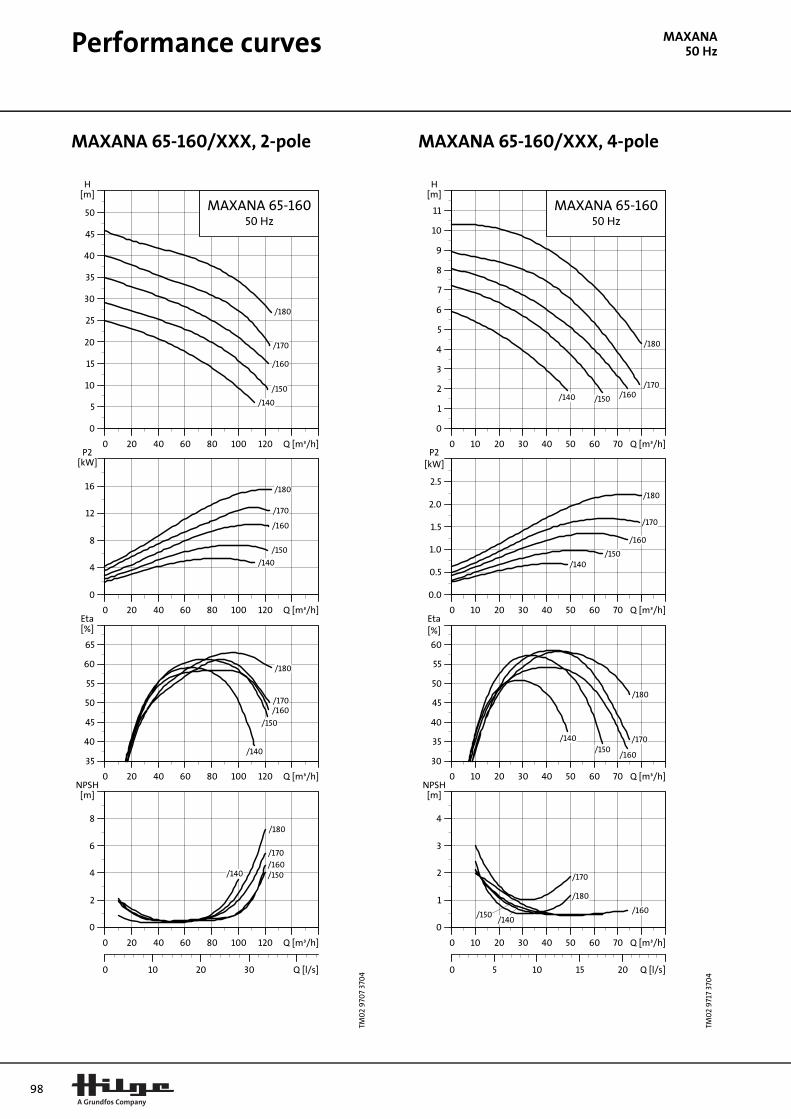
98
Performance curves
MAXANA50 HzMAXANA 65-160/XXX, 2-pole MAXANA 65-160/XXX, 4-pole
TM0
2 9
707
370
4
0 20 40 60 80 100 120 Q [m³/h]
0
5
10
15
20
25
30
35
40
45
50
H[m]
MAXANA 65-16050 Hz
/140
/150
/160
/170
/180
0 20 40 60 80 100 120 Q [m³/h]
0
4
8
12
16
P2[kW]
/140
/150
/160
/170
/180
0 20 40 60 80 100 120 Q [m³/h]
35
40
45
50
55
60
65
[%]Eta
/140
/150
/160/170
/180
0 20 40 60 80 100 120 Q [m³/h]
0
2
4
6
8
[m]NPSH
0 10 20 30 Q [l/s]
/140 /150/160
/170
/180
TM0
2 9
717
370
4
0 10 20 30 40 50 60 70 Q [m³/h]
0
1
2
3
4
5
6
7
8
9
10
11
H[m]
MAXANA 65-16050 Hz
/140 /150 /160/170
/180
0 10 20 30 40 50 60 70 Q [m³/h]
0.0
0.5
1.0
1.5
2.0
2.5
P2[kW]
/140/150
/160
/170
/180
0 10 20 30 40 50 60 70 Q [m³/h]
30
35
40
45
50
55
60
[%]Eta
/140/150
/160
/170
/180
0 10 20 30 40 50 60 70 Q [m³/h]
0
1
2
3
4
[m]NPSH
0 5 10 15 20 Q [l/s]
/160/150/140
/170
/180
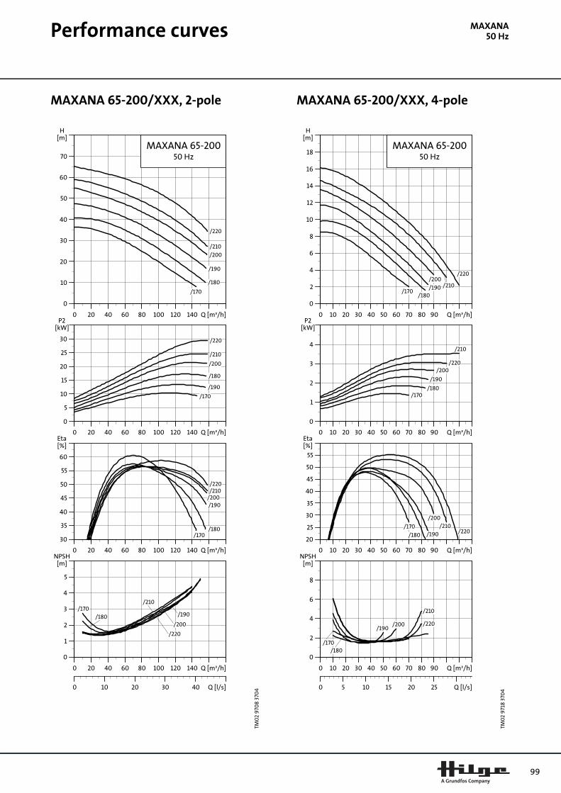
Performance curves
MAXANA50 HzMAXANA 65-200/XXX, 2-pole MAXANA 65-200/XXX, 4-pole
TM0
2 9
708
370
4
0 20 40 60 80 100 120 140 Q [m³/h]
0
10
20
30
40
50
60
70
H[m]
MAXANA 65-20050 Hz
/170
/180
/190
/200
/210
/220
0 20 40 60 80 100 120 140 Q [m³/h]
0
5
10
15
20
25
30
P2[kW]
/170
/180
/190
/200
/210
/220
0 20 40 60 80 100 120 140 Q [m³/h]
30
35
40
45
50
55
60
[%]Eta
/170/180
/190/200/210/220
0 20 40 60 80 100 120 140 Q [m³/h]
0
1
2
3
4
5
[m]NPSH
0 10 20 30 40 Q [l/s]
/170/180 /190
/200
/210
/220
TM0
2 9
718
370
4
0 10 20 30 40 50 60 70 80 90 Q [m³/h]
0
2
4
6
8
10
12
14
16
18
H[m]
MAXANA 65-20050 Hz
/170/180
/190
/200/210
/220
0 10 20 30 40 50 60 70 80 90 Q [m³/h]
0
1
2
3
4
P2[kW]
/170/180
/190
/200
/210
/220
0 10 20 30 40 50 60 70 80 90 Q [m³/h]
20
25
30
35
40
45
50
55
[%]Eta
/170
/180 /190
/200/210
/220
0 10 20 30 40 50 60 70 80 90 Q [m³/h]
0
2
4
6
8
[m]NPSH
0 5 10 15 20 25 Q [l/s]
/180/170
/190/200
/210
/220
99
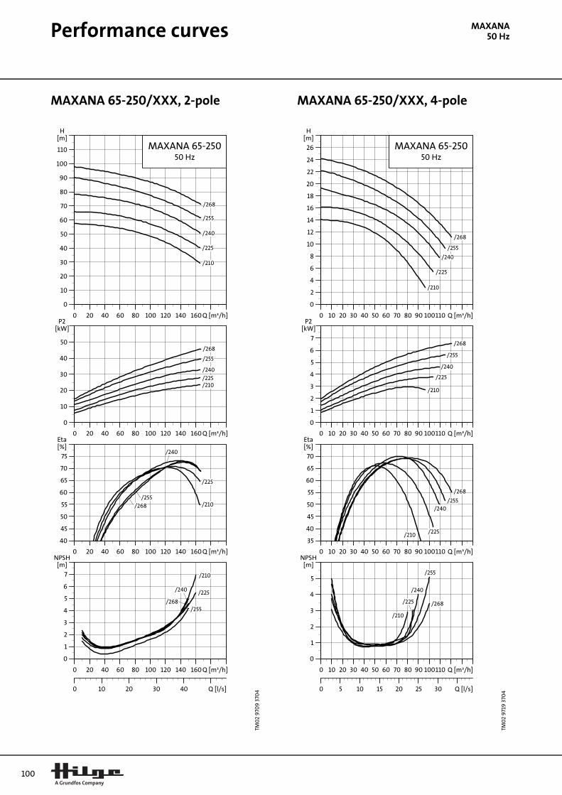
100
Performance curves
MAXANA50 HzMAXANA 65-250/XXX, 2-pole MAXANA 65-250/XXX, 4-pole
TM0
2 9
709
370
4
0 20 40 60 80 100 120 140 160 Q [m³/h]
0
10
20
30
40
50
60
70
80
90
100
110
H[m]
MAXANA 65-25050 Hz
/210
/225
/240
/255
/268
0 20 40 60 80 100 120 140 160 Q [m³/h]
0
10
20
30
40
50
P2[kW]
/210/225
/240
/255
/268
0 20 40 60 80 100 120 140 160 Q [m³/h]
40
45
50
55
60
65
70
75
[%]Eta
/210
/225
/240
/255/268
0 20 40 60 80 100 120 140 160 Q [m³/h]
0
1
2
3
4
5
6
7
[m]NPSH
0 10 20 30 40 Q [l/s]
/210
/225/240
/255/268
TM0
2 9
719
370
4
0 10 20 30 40 50 60 70 80 90 100110 Q [m³/h]
0
2
4
6
8
10
12
14
16
18
20
22
24
26
H[m]
MAXANA 65-25050 Hz
/210
/225
/240
/255
/268
0 10 20 30 40 50 60 70 80 90 100110 Q [m³/h]
0
1
2
3
4
5
6
7
P2[kW]
/210
/225
/240
/255
/268
0 10 20 30 40 50 60 70 80 90 100110 Q [m³/h]
35
40
45
50
55
60
65
70
[%]Eta
/210 /225
/240/255
/268
0 10 20 30 40 50 60 70 80 90 100110 Q [m³/h]
0
1
2
3
4
5
[m]NPSH
0 5 10 15 20 25 30 Q [l/s]
/210
/225
/240
/255
/268

Technical data
MAXANA50 HzMAXANA Adapta® on stainless steel foot
Technical data
TM0
2 9
652
36
04
Pumpsize
P2 [kW] IEC size k3 u(1) a1 h2 p(4) b DNs(6) DNd
(6) Net weight [kg]
32-160
3.0 100L 320 175 80 160 264 0
50(65)
32(40)
71
4.0 112M 340 185 80 160 264 0 78
5.5 132S 390 205 80 160 264 20 90
32-200
3.0 100L 320 175 80 180 316 0 77
4.0 112M 340 185 80 180 316 0 84
5.5 132S 390 205 80 180 316 20 96
7.5 132S 390 205 80 180 316 20 106
11.0 160M 490 240 80 180 316 51 127
15.0 160M 490 240 80 180 316 51 138
40-160
4.0 112M 340 195 80 160 264 0
65(80)
40(50)
79
5.5 132S 390 205 80 160 264 20 91
7.5 132S 390 205 80 160 264 20 101
11.0 160M 490 240 80 160 264 51 140
40-200
7.5 132S 390 205 100 180 316 20 107
11.0 160M 490 290 100 180 316 51 126
15.0 160M 490 290 100 180 316 51 139
50-125
3.0 100L 320 175 100 160 264 0
50(65)
76
4.0 112M 340 185 100 160 264 0 83
5.5 132S 390 205 100 160 264 20 95
7.5 132S 390 205 100 160 264 20 105
50-160
5.5 132S 390 205 100 180 288 20 93
7.5 132S 390 205 100 180 288 20 103
11.0 160M 490 240 100 180 288 51 115
15.0 160M 490 240 100 180 288 51 135
50-20011.0 160M 490 240 100 200 316 51 129
15.0 160M 490 240 100 200 316 51 142
65-125
4.0 112M 340 185 100 180 288 0
80(100)
65(80)
86
5.5 132S 390 205 100 180 288 20 98
7.5 132S 390 205 100 180 288 20 108
65-160
5.5 132S 390 205 100 200 308 20 98
7.5 132S 390 205 100 200 308 20 108
11.0 160M 490 240 100 200 308 51 127
15.0 160M 490 240 100 200 308 51 140
65-20011.0 160M 490 240 100 225 348 51 134
15.0 160M 490 240 100 225 348 51 147
Dimensions depend on housing size (DNs, DNd, a1, h2), see table of connections on page 36.
(1) Motor dimensions depend on make, max. size for basic design given.
(2) Flange dimensions are according to DIN EN 1092-1 (DIN 2632). Nominal diameter in parenthesis are available on request.
(4) Largest diameter of pump without motor.
(7) N-Eupex coupling.
101

102
Technical data
MAXANA50 HzMAXANA Adapta® on Adapta® foot
Technical data
TM0
3 0
183
440
4
100
250
390
P2 [kW] n [min-1] IEC size b k3(1) u(1)
15.0 2900 160M - 490 240
18.5 2900 160L - 530 240
22.0 2900 180L - 605 265
30.0 2900 200L 25 665 310
37.0 2900 200L 25 665 310
45.0 2900 225M 30 700 330
(1) Motor dimensions depend on make, max. size for basic design given.
(2) Other sizes and special connections are available on request.
(7) N-Eupex coupling.

Technical data
MAXANA50 HzMAXANA Bloc on pump and motor foot
Technical data, 2-pole
TM0
3 0
202
450
4
250
1
Pumpsize
P2 [kW]
IEC size k3(1) u(1) a1 h1 h2 p(4) m1 m2 n1 n2 b DNs
(2) DNd(2)
Net weight
[kg]
32-160
2.2 90L 285 150 80 132 160 264 100 70 240 190 50
50(65)
32(40)
34
3.0 100L 320 175 80 132 160 264 100 70 240 190 50 40
4.0 112M 340 185 80 132 160 264 100 70 240 190 50 47
5.5 112M 340 185 80 132 160 264 100 70 240 190 50 59
32-200
3.0 100L 320 175 80 160 180 316 100 70 240 190 50 46
4.0 112M 340 185 80 160 180 316 100 70 240 190 50 53
5.5 112M 340 185 80 160 180 316 100 70 240 190 50 65
40-1604.0 112M 340 185 80 132 160 264 100 70 240 190 50
65(80)
40(50)
48
5.5 112M 340 185 80 132 160 264 100 70 240 190 50 60
50-125
3.0 100L 320 175 100 132 160 264 100 70 240 190 50
50(65)
45
4.0 112M 340 185 100 132 160 264 100 70 240 190 50 52
5.5 112M 340 185 100 132 160 264 100 70 240 190 50 64
50-160 5.5 112M 340 185 100 160 180 288 100 70 265 212 50 62
65-1254.0 112M 340 185 100 160 180 288 125 95 280 212 65
80(100)
65(80)
55
5.5 112M 340 185 100 160 180 288 125 95 280 212 65 67
65-160 5.5 112M 340 185 100 160 200 308 125 95 280 212 65 67
103

104
Technical data
MAXANA50 HzTechnical data, 4-pole
Pumpsize
P2 [kW]
IEC size k3(1) u(1) a1 h1 h2 p(4) m1 m2 n1 n2 b DNs
(2) DNd(2)
Net weight
[kg]
32-1600.55 80 245 145 80 132 160 264 100 70 240 190 50
50(65)
32(40)
27
0.75 90S 285 150 80 132 160 264 100 70 240 190 50 28
32-200
0.75 90S 285 150 80 160 180 316 100 70 240 190 50 34
1.1 90S 285 150 80 160 180 316 100 70 240 190 50 37
1.5 90L 285 150 80 160 180 316 100 70 240 190 50 40
40-160
0.55 80 245 145 80 132 160 264 100 70 240 190 50
65(80)
40(50)
28
0.75 90S 285 150 80 132 160 264 100 70 240 190 50 29
1.1 90S 285 150 80 132 160 264 100 70 240 190 50 32
1.5 90L 285 150 80 132 160 264 100 70 240 190 50 35
40-200
1.1 90S 285 150 100 160 180 316 100 70 265 212 50 38
1.5 90L 285 150 100 160 180 316 100 70 265 212 50 41
2.2 100L 320 175 100 160 180 316 100 70 265 212 50 48
50-125
0.55 80 245 145 100 132 160 264 100 70 240 190 5050
(65)
32
0.75 90S 285 150 100 132 160 264 100 70 240 190 50 33
1.1 90S 285 150 100 132 160 264 100 70 240 190 50 36
50-160
1.1 90S 285 150 100 160 180 288 100 70 265 212 50
40(50)
34
1.5 90L 285 150 100 160 180 288 100 70 265 212 50 38
2.2 100L 320 175 100 160 180 288 100 70 265 212 50 44
50-200
1.5 90L 285 150 100 160 200 316 100 70 265 212 50 44
2.2 100L 320 175 100 160 200 316 100 70 265 212 50 51
3.0 100L 320 175 100 160 200 316 100 70 265 212 50 53
4.0 112M 340 185 100 160 200 316 100 70 265 212 50 58
65-1250.75 90S 285 150 100 160 180 288 125 95 280 212 65
80(100)
65(80)
36
1.1 90S 285 150 100 160 180 288 125 95 280 212 65 39
65-160
0.75 90S 285 150 100 160 200 308 125 95 280 212 65 36
1.1 90S 285 150 100 160 200 308 125 95 280 212 65 39
1.5 90L 285 150 100 160 200 308 125 95 280 212 65 43
2.2 100L 320 175 100 160 200 308 125 95 280 212 65 49
3.0 100L 320 175 100 160 200 308 125 95 280 212 65 51
65-200
1.5 90L 285 150 100 180 225 348 125 95 320 250 65 50
2.2 100L 320 175 100 180 225 348 125 95 320 250 65 56
3.0 100L 320 175 100 180 225 348 125 95 320 250 65 58
4.0 112M 340 185 100 180 225 348 125 95 320 250 65 63
5.5 112M 340 185 100 180 225 348 125 95 320 250 65 76
Dimensions depend on housing size (DNs, DNd, a1, h2), see table of connections on page 36.
(1) Motor dimensions depend on make, max. size for basic design given.
(2) Flange dimensions are according to DIN EN 1092-1 (DIN 2632). Nominal diameter in parenthesis are available on request.
(4) Largest diameter of pump without motor.

Technical data
MAXANA50 HzMAXANA Bloc on motor foot
Technical data
TM0
3 0
201
450
4
250
Pumpsize
P2 [kW] IEC size a1 h1 h2 p m1 m2 n1 n2 h9 s1 DNs(2) DNd
(2)Net
weight [kg]
32-200
7.5 132S 80 132 180 316 180 140 256 216 15 1250
(65)32
(40)
75
11.0 132S 80 132 180 316 180 140 256 216 15 12 94
15.0 160M 80 160 180 316 256 210 300 254 18 15 107
40-1607.5 132S 80 132 160 264 180 140 256 216 15 12
65(80)
40(50)
70
11.0 132S 80 132 160 264 180 140 256 216 15 12 89
40-200
7.5 132S 100 132 180 316 180 140 256 216 15 12 76
11.0 132S 100 132 180 316 180 140 256 216 15 12 95
15.0 160M 100 160 180 316 256 210 300 254 18 15 108
18.5 160L 100 160 180 316 300 254 300 254 18 15 125
50-125 7.5 132S 100 132 160 264 180 140 256 216 15 12
50(65)
74
50-160
7.5 132S 100 132 180 288 180 140 256 216 15 12 72
11.0 132S 100 132 180 288 180 140 256 216 15 12 91
15.0 160M 100 160 180 288 256 210 300 254 18 15 104
18.5 160L 100 160 180 288 300 254 300 254 18 15 121
50-200
11.0 132S 100 132 200 316 180 140 256 216 15 12 98
15.0 160M 100 160 200 316 256 210 300 254 18 15 111
18.5 160L 100 160 200 316 300 254 300 254 18 15 128
22.0 160L 100 160 200 316 300 254 300 254 18 15 149
65-125 7.5 132S 100 132 180 288 180 140 256 216 15 12
80(100)
65(80)
77
65-160
7.5 132S 100 132 200 308 180 140 256 216 15 12 77
11.0 132S 100 132 200 308 180 140 256 216 15 12 96
15.0 160M 100 160 200 308 256 210 300 254 18 15 109
18.5 160L 100 160 200 308 300 254 300 254 18 15 126
22.0 160L 100 160 200 308 300 254 300 254 18 15 147
65-200
11.0 132S 100 132 225 348 180 140 256 216 15 12 103
15.0 160M 100 160 225 348 256 210 300 254 18 15 116
18.5 160L 100 160 225 348 300 254 300 254 18 15 133
22.0 160L 100 160 225 348 300 254 300 254 18 15 154
Dimensions depend on housing size (DNs, DNd, a1, h2), see table of connections on page 36.
(1) Motor dimensions depend on make, max. size for basic design given.
(2) Flange dimensions are according to DIN EN 1092-1 (DIN 2632). Nominal diameter in parenthesis are available on request.
(4) Largest diameter of pump without motor.
105

106
ntation
Further product documeIn addition to printed data booklets, Grundfos offersproduct documentation in WebCAPS.
WebCAPSWebCAPS is a Web-based Computer Aided-ProductSelection program and a web-version of WinCAPS.
Available on Grundfos’ homepage, www.grundfos.com,WebCAPS offers
• detailed technical information
• dimensional drawings of each pump
• wiring diagrams of each pump.
Fig. 36 WebCAPS
Web
CA
PS
Click Catalogue andselect a product fromthe extensiveproduct catalogue.
Click Replacementand select the rightreplacement pumpbased on thecurrent installation.
Click Productsearch and selecta product from theextensive productcatalogue.
Click Service toto find informationon service kits andspare parts.
Click Units and select yourpreferred units of measurement:- Default units- SI units- US units.
Click Language andselect your preferredlanguage.
Click Literature toselect and downloadGrundfos documentationby browsing the productranges or performinga specific search. Theliterature includes:- Data booklets- Installation and
- Service instructions.operating instructions
If you are a registereduser click Log in to:- save your settings- define and save your
own units- save personalised
information.

107

www.hilge.de
Switzerland:Hilge Pumpen AGHilgestrasse6247 Schötz/LUPhone: +41 (0)41-984 2842Fax: +41 (0)41-984 2852Email: [email protected]
France:Pompes Hilge Sarl8, route de Mandres94440 SantenyPhone: +33(0)1-4386 1515Fax: +33(0)1-4386 1567Email: [email protected]
Germany:Philipp Hilge GmbH & Co. KG
Hilgestrasse 37-47D-55294 Bodenheim
Phone: +49(0)6135-75 0Fax: +49(0)6135-17 37Email: [email protected]
United Kingdom:Hilge Pumps Ltd.Hawthorn RoadEastbourneEast Sussex BN23 6QAEnglandPhone: +44(0)1323-438 333Fax: +44(0)1323-410 004Email: [email protected]
India:Kishor Hilge Pumps Pvt. Ltd.“Shriraj”94/25B Prabhat RoadErandavanePune 411 004Phone: +91(0)20-256 73 702Fax: +91(0)20-256 73 702Email: [email protected]