Embed Size (px)
Citation preview
The University of Newcastle
Infrastructure and Facilities Services
Installation Specification
High Voltage Substation Specification
25th June 2019
Version 1
UON-ESS-113
Revision Record
Version Date Description Prepared by: Checked by: Approved by:
Draft 05/02/2019 Issued for Approval R.Eyre Tim Fox R.Eyre
1 26/03/2019 Released R Eyre Tim Fox R.Eyre
2 25/06/2019 Revised R Eyre D Batzke R.Eyre
University of Newcastle Specification UON-ESS-113 High Voltage Substation Specification – Version 1
Contents
1. INTRODUCTION ......................................................................................................................................... 4
2. STANDARDS, SPECIFICATIONS AND STATUTORY OBLIGATIONS ................................................................. 4
3. BACKGROUND ........................................................................................................................................... 6
4. SCOPE ........................................................................................................................................................ 6
5. SUBSTATION BUILDING ............................................................................................................................. 6
5.1. Access ....................................................................................................................................... 6
5.2. Layout and Facilities .................................................................................................................. 7
5.3. Lighting and Small Power .......................................................................................................... 7
5.4. Connection to UON Network ..................................................................................................... 8
5.5. EMF ........................................................................................................................................... 8
6. TRANSFORMERS ........................................................................................................................................ 8
6.1. General ...................................................................................................................................... 8
6.2. Electrical Specification .............................................................................................................. 9
6.3. Miscellaneous fittings ................................................................................................................ 9
6.4. Oil containment bund ................................................................................................................ 9
7. SWITCHGEAR ............................................................................................................................................. 9
8. POWER FACTOR CORRECTION ................................................................................................................. 10
9. METERING ............................................................................................................................................... 10
9.1. High Voltage Metering .............................................................................................................10
9.2. Low Voltage Metering ..............................................................................................................11
Building Main Switchboard ..................................................................................................................11
9.3. Distribution Boards ..................................................................................................................12
10. REMOTE MONITORING ....................................................................................................................... 14
10.1. EMS Network Configuration and Topology .............................................................................15
11. ALARMING .......................................................................................................................................... 16
12. VENTILATION ...................................................................................................................................... 17
13. EARTHING ........................................................................................................................................... 17
14. ANCILLARY EQUIPMENT ...................................................................................................................... 17
15. TESTING .............................................................................................................................................. 17
16. DRAWINGS AND DOCUMENTATION .................................................................................................... 18
17. DEFECT LIABILITY PERIOD .................................................................................................................... 18
18. MISCELLANEOUS ................................................................................................................................. 18
4 | P a g e University of Newcastle Specification UON-ESS-113 High Voltage Substation Specification – Version 1
1. Introduction
This specification covers the general requirements applicable to the design, manufacture, installation performance and delivery of electrical substations at the UON (University of Newcastle). It is not the intention to specify details of design and construction except where necessary to establish performance requirements, nor is it the intention to set forth those performance requirements which are adequately specified by the applicable standards. This specification shall be read in conjunction with Standard Specification UON-ESS-101 General Electrical Specification.
2. Standards, Specifications and Statutory Obligations
All aspects of design, manufacture, testing, supply, plant, equipment, accessories, materials, construction, erection, installation, operation and performance shall comply with this specification and the current issue of the relevant Australian Standards, the relevant International Standards, the UON Standard Specifications and Preferred Equipment List, as well as all Statutory Acts, Codes, Regulations and Requirements of the relevant Authorities having jurisdiction over them unless specified otherwise within this Specification. These shall include but not be limited to:
Australian/International Standards
AS 3000 Wiring Rules AS 2374 Power Transformers AS 3010 Electrical Installations AS 1768 Lightning Protection AS 2053 Conduits and fittings for electrical installations AS 2629 Separable insulated connectors for power distribution systems above
1kV AS 2978 Insulating mats for electrical purposes AS 3017 Electrical installations – Testing and inspection guidelines AS 3731 Stationary Batteries - Nickel-cadmium AS 4029 Stationary Batteries – Lead-acid AS 4044 Battery chargers for stationary batteries AS 1243 Voltage transformers for measurement and protection AS 1265 Bushings for alternating voltages above 1000 V AS 1931 High-voltage test techniques AS 2006 High voltage ac switchgear and controlgear – Circuit breakers for
rated voltages above 1000 V AS 2067 Switchgear assemblies and ancillary equipment for alternating
voltages above 1 kV AS 2086 AC metal-enclosed switchgear and controlgear for rated voltages
above 1 kV and up to and including 72.5 kV AS 2395 Terminals for switchgear assemblies for alternating voltages above 1
kV AS 2650 Common specifications for high-voltage switchgear and controlgear
standards AS 3132 Approval and test specification – Enclosures of insulating material for
switchgear and controlgear AS 2732 Guide to the lightning impulse and switching impulse testing of power
transformers and reactors AS 2067 Substations and High Voltage Installations exceeding 1kV AC AS 5577 Electricity Network Safety Management Systems
5 | P a g e University of Newcastle Specification UON-ESS-113 High Voltage Substation Specification – Version 1
ENA 15 Energy Network Australia - National Guideline for Prevention of Unauthorised Access to Electricity Infrastructure
ENA 18 Energy Network Australia - Fire protection of Electricity Substations
University of Newcastle Standards
UON-ESS-101 General Electrical Specification UON-ESS-102 Distribution Board Specification UON-ESS-103 External Lighting Spec Draft final UON-ESS-104 Emergency Escape Lighting and Illuminated Exit Signage UON-ESS-105 Preferred equipment list UON-ESS-106 Generators UON-ESS-109 Substations UON-ESS-110 Uninterruptable Power Supply UON-ESS-111 Interior Lighting and Control UON-ESS-112 Main Switchboard Specification. UON-DSS-001 CAD Drafting Standards
Authorities and Statutory Acts, Codes, Regulations and Requirements
Electricity Supply Act 1995 (NSW) NSW Service and Installation Rules National Electricity Rules Electricity Supply (General) Regulation 2014 (NSW) Electricity Supply (Safety and Network Management) Regulation 2014 Work Health and Safety Act 2011 and Regulation 2011
Where the stipulations of this specification, data sheets and drawings do not comply with the minimum requirements of the Australian Standards or Statutory Regulations, the latter shall prevail. Where the stipulations of this specification, the data sheets and the drawings are more exacting than the minimum requirements of the Australian Standards and Statutory Regulations, the former shall prevail in the following order:
a) Data sheets and detail drawings b) Specification and standard drawings
6 | P a g e University of Newcastle Specification UON-ESS-113 High Voltage Substation Specification – Version 1
3. Background
The UON is different to most other power consumers. Apart from the larger quantities of power used by the university, the power supplied to UON is High Voltage (11000V). The UON purchases this higher voltage power and owns and operates its own High Voltage Network to distribute power around campus. The UON high voltage network is made up of 22 substations connected by approximately 4km of underground cable over around 350 acres. The network is divided into four separate sections: NIER, East Campus, West Campus and Accommodation. Each section has a separate Ausgrid supply. West Campus also has a redundant supply. The Ausgrid supply enters the campus at Substation 1, Substation 10, Substation 18 and Substation 19. Ausgrid’s Authority and responsibilities end at the above four substations.
4. Scope
This specification is intended as instruction for the design, supply and installation of Electrical Substations and associated equipment at the University of Newcastle. This is not a comprehensive specification, this specification covers the design, supply and installation preferences and the unique requirements that are associated with an installation at the University of Newcastle. Areas not covered by this specification should be completed as per Australian Standard, to industry best practice and in a ‘tradesman like manner.
5. Substation Building
5.1. Access
Building access shall be designed to facilitate the movement of equipment, personnel and associated vehicles. Personnel entry doors must have internal pushbars to exit and default to the locked condition when closed. All personnel doors shall be fitted with door closers. All personnel entry doors shall be fitting with a UON HV1 keyed lock for access to High Voltage Areas and a UON HV2 keyed lock for Low voltage area access. In addition to Personnel entry doors, all substations shall have double entry doors large enough to accommodate the largest piece of equipment housed in that substation. The double door access shall have a landing immediately outside the opening capable of receiving the largest piece of equipment housed in that substation. If this landing is higher than the surrounding area by more than 225mm, a removable or gated handrail shall be installed. The double doors shall NOT utilise an internal pushbar for opening. There shall be no way of opening the double doors externally. Standard door bold shall be used to secure the double doors internally. If a substation is directly connected to the Ausgrid network such as Sub 1, Sub 10, Sub 18 or Sub 19 all High Voltage personnel doors shall be fitted with dual locking allowing access using both the UON HV1 key and the Ausgrid Substation Access key. All substations shall have paved vehicle access with car parking for a minimum of two standard size vehicles. Paved Vehicle access shall give direct access to the substation double entry doors. The double door vehicle access can be used to satisfy the car parking requirements. Signage shall be installed in front of the double door access stating “No Stopping High Voltage Substation access only”.
7 | P a g e University of Newcastle Specification UON-ESS-113 High Voltage Substation Specification – Version 1
5.2. Layout and Facilities
Equipment within the substation shall be positioned to allow maintenance access to removable panel. Effort should be made to keep the area directly in front of the High Voltage switchgear clear. A minimum of 1.2 meters between the High Voltage switchgear front panel and adjacent equipment should be maintained all times. There shall be a minimum separation distance of 1 meter between transformers or transformer components. The battery charger controls/interface shall be at a height of at least one meter from the floor to allow access by the user. Remote switching interface shall be housed in the LV section of the substation and a minimum of 1.2 meters from the substation floor. All HV or LV switching tools shall be mounted on a tool board showing the outline of the tool to facilitate relocation. HV tools shall be mounted with purpose made proprietary mounting brackets. Both LV and HV sides of the substation shall have tag holder mounted on the wall to house equipment tags. Each tag holder shall accommodate three different types of tags, with room to store 20 of each type. The HV side of the substation shall have a locker for the purpose of housing protective clothing. This locker shall be a minimum of 1800mm height to allow hanging and storage of full body protective suites. The lockers shall be capable of housing two suites. Storage shall also be provided for High voltage test equipment, safety equipment, earthing cable and other associated equipment. All equipment and safety lockers shall be reasonably sealed to prevent dust ingress. Within the HV side of the substation, a surface shall be provided for the reading of drawings and filling out of switching permits. This surface area shall be at least 1200mm x 600mm. Ideally, this surface would be a drawing board attached to the wall. A full sets of A3 size drawings shall be provided in protective sleeves housed in a folder for both the HV and LV sections of the substation. Signage as per the NSW Service and Installation rules shall be installed in each substation. Network drawings shall be A2, framed, protected by glass or Perspex (or similar) and capable of being changed when drawing updates are required.
5.3. Lighting and Small Power
All lighting and small power is to be installed as per relevant UON Electrical Specification UON-ESS-111 Interior Lighting and Control. A distribution board shall be installed in each substation to control lighting and small power within the substation and external lighting. The substation may also supply lighting for roads and walkways in the general area of the substation. At least one GPO for every eight lineal meters of wall shall be provided within both the LV and HV sides of the substation. GPO’s shall be heavy duty type (Clipsal 56 series or similar). Lighting within the substation shall not be mounted above equipment or in such a way that it cannot be accessed from a step ladder on level ground. Light levels within the substation shall be between 160 – 400 Lux. Any glass tubes or bulbs within the light fitting shall be completely enclosed for mechanical protection and to capture debris in the event of breakage. Lighting shall be directly switched using two way switching, one switch at each personnel door. All switches and electrical outlets shall be heavy duty type (Clipsal 56 series or similar). If emergency escape light and exists signs are required by the NCC, they shall be installed as per AS 2293. If emergency escape lighting and exit signs are not required by the NCC, Emergency
8 | P a g e University of Newcastle Specification UON-ESS-113 High Voltage Substation Specification – Version 1
escape lighting only shall be installed. Emergency escape lighting in substation need not be connected to a monitoring system. If the substation is of a size that required emergency escape lighting and exit signs such lighting shall be installed as per AS2293. If emergency escape lighting and exit signs are not required by the NCC, emergency escape lighting only shall be installed. Location of this lighting shall be as per AS2293 requirements. Emergency escape lighting in substation need not be connected to a monitored system.
External lights shall be provided above all entry and exit doors. The remainder of the substation perimeter shall be maintained at P2 light levels. External lighting shall be controlled by a PE cell.
5.4. Connection to UON Network
All substations shall include at least one wireless access point and two Copper (RJ45) connections accessing the UON network.
5.5. EMF
In some situations, site selection of the substation may also be important in reducing EMF. EMF shielding may be required in some circumstances. A substation shall not be located adjacent to, above, or below operating theatres or similar areas where sensitive instrumentation are to be installed. (Refer also to AS/NZS 3003:2011 Electrical installations - Patient areas).
6. Transformers
6.1. General
Transformers in Chamber Substations shall be
Designed for a minimum 50 year life
Indoor oil immersed and sealed
Not be pressurised
Incorporate no gases other than air
Utilise ONAN cooling
Fitted with Air Insulated cable boxes
Mounted on Bi-directional rollers
Contain copper windings
Storm Grey
HV Bottom entry/LV top entry
Sound less than 80dB @ 1 meter
Mineral Oil insulated
Jacked off rollers and bolted down once into position
Fitted with lifting lugs
Cores constructed with non-aging transformer steel
HV and LV cables supported to take load of cable glands and terminations
Contain less than 1ppm PCBs Transformer spaces must be separated from other transformers, walls, other equipment, pit edges or obstructions by at least 1000 mm. All conduits must be clear of the path required for installation or removal of any transformer. Transformers must not be placed directly under ventilation duct openings.
9 | P a g e University of Newcastle Specification UON-ESS-113 High Voltage Substation Specification – Version 1
6.2. Electrical Specification
Phases 3
Vector connection Dyn11
Frequency 50 Hz
Rated primary voltage 11 kV
Rated no-load secondary voltage 433 V
Include Offline Tap Changer
All control wiring will be ferruled with wire numbers and terminated into IP54 marshalling enclosure that is accessible from floor level
Come with a complete set or control wiring diagrams
6.3. Miscellaneous fittings
Pressure Relief Valve complete with protection trip relay
Provide a suitable stainless steel earthing stud M12 x 40 long complete with stainless steel nuts and washers on the transformer frame for earthing the unit
All control/monitoring to be factory wired to an accessible terminal strip, mounted within an IP54 cubicle on the transformer
Oil filling hole and cap
Oil level indicator (clear glass)
Oil drain valve with threaded steel plug
Nameplate as per AS 60076.1 Section 7 & AS 60076.11 Section 9
Include statement confirming that transformer complies with AS2374.1.2 (Minimum Energy Performance Standard)
6.4. Oil containment bund
An oil containment system shall be provided in accordance with AS 2067. Bunded areas and Bund walls shall be of reinforced concrete. Suitable construction/control joints (including water stops as necessary) shall be installed to prevent bund cracking.
7. Switchgear
The University of Newcastle uses Schneider Premset High Voltage Circuit breakers with Sepam Protection Relays. If the Circuit breaker is located at either end of a section of the High Voltage ring, translay differential protection shall also be installed. The position of the actual equipment, primary and earthing contacts within the switchgear shall be capable of being visually verified via viewing windows. Lighting shall be included to ensure that mechanisms can be clearly seen by the operator through the viewing windows. All High Voltage circuit breaker installations shall include a remote panel to allow the switchgear to be operated from outside the room housing the switchgear. Unless otherwise advised by the University, this remote panel shall be located in the adjacent Low Voltage switch room. Switchgear status shall be displayed on the remote operating panel and within Power Studio. All networking and configuration required to display the switchgear status on Power Studio shall be included in any installation proposal. A third party provider is to be used to configure Power Studio.
10 | P a g e University of Newcastle Specification UON-ESS-113 High Voltage Substation Specification – Version 1
8. Power Factor Correction
Power Factor Correction shall be provided in all substations directly connected to the Ausgrid network.
9. Metering
Below is the metering strategy for the power reticulation at UON.
9.1. High Voltage Metering
High Voltage incomers Any High Voltage feeder that is directly connected to the Ausgrid network will have two meters monitor power and energy usage in addition to the Ausgrid revenue meter. The first meter shall be a PM5350 meter that is used to audit billing from the UON Electricity Provider. This meter will be mounted in a separate enclosure within the Low Voltage section of the Substation. The energy usage data from this meter also needs to be collected and displayed within Power Studio. The above meter installation must include all networking and configuration required to compile this information within Power Studio. In addition to the PM5350, the Sepam unit within the High Voltage switchgear shall be used to provide additional information on the High Voltage installation. Below is a list of information that shall be extracted from the Sepam unit and displayed within Power Studio:
Voltage, Line and Phase
Phase Currents
Frequency
P,Q and S Power
Power Factor
Energy usage
Peak Demand (current) Any installation of the above Sepam meter must include all networking and configuration required to compile and display this information within Power Studio. A third party provider to be used to configure Power Studio. High Voltage Feeders High voltage circuit breakers that are not directly connected the Ausgrid network will utilise the Sepam protection relay to monitor network conditions. Below is a list of information that shall be extracted from the Sepam unit and displayed within Power Studio for each High Voltage feeder/circuit breaker.
Voltage, Line and Phase
Phase Currents
Frequency
P,Q and S Power
Power Factor
Energy usage
Peak Demand (Current)
Any installation of the above Sepam meter must include all networking and configuration required to compile and display the information listed above within Power Studio. A third party provider to be used to configure Power Studio.
11 | P a g e University of Newcastle Specification UON-ESS-113 High Voltage Substation Specification – Version 1
9.2. Low Voltage Metering
Low Voltage Substation
All inputs to the Low Voltage substation switchboards shall be metered using a PM5350. This switchboard is typically directly connected to the Substation transformer and supplies power to the main switchboards located in each separate building. All feeds originating at the Low Voltage Substation Switchboard shall be metered using PM5350. Meters are not to be mounted in functional units or and other part of the switchboard. These meters shall be housed in a purpose built enclosure within the Low Voltage Section of the substation. High Voltage and Low Voltage metering can be mounted within the same enclosure if clearly marked with “High Voltage Metering” and “Low Voltage Metering”. Below is a list of information that shall be extracted from the PM5350 meters attached to the Low Voltage Substation switchboard and displayed within Power Studio.
Voltage, Line and Phase
Phase Currents
Frequency
P,Q and S Power
Power Factor
Energy usage
Peak Demand (Current) Any installation of the above meters on a Low Voltage Substation switchboard must include all networking and configuration required to compile and display the information listed above within Power Studio. A third party provider to be used to configure Power Studio.
Building Main Switchboard
All feeds originating at the Building Main Switchboard shall be metered using PM5350. Main switchboard meters should be housed separate to the switchboard. Meters are not to be mounted in functional units or and other part of the switchboard. Meters should be housed in a separate designated enclosure. Below is a list of information that shall be extracted from the PM5350 meters attached to the Main Switchboard and displayed within Power Studio.
Voltage, Line and Phase
Phase Currents
Frequency
P,Q and S Power
Power Factor
Energy usage
Peak Demand (Current)
Any installation of the above meters on a Main switchboard must include all networking and configuration required to compile and display the information listed above within Power Studio. Third party provider to be used to configure Power Studio. Additional metering may be required downstream of the Main Switchboard if the function unit within the Main Switchboard supplies a Mechanical Services Switchboard. The metering within the Mechanical Services Switchboard will depend on the requirements of NCC Section J and the UON Mechanical Engineer.
12 | P a g e University of Newcastle Specification UON-ESS-113 High Voltage Substation Specification – Version 1
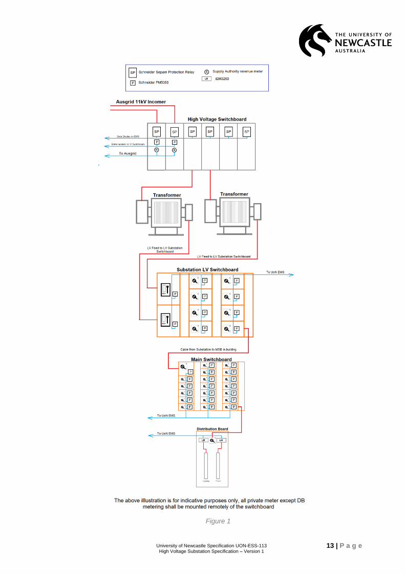
9.3. Distribution Boards
All distribution boards shall have an individual Lighting and Power Meters. All power used by devices connected to a Distribution Board shall be captured by metering within that board. Meters within a DB shall be DIN mounted iEM3250 type. Access to the meter shall be maintained with the DB escutcheon closed. Meters shall not be mounted on any removable or hinged panel. Below is a list of information that shall be extracted from the Distribution Board iEM3250 meters and displayed within Power Studio:
Voltage, Line and Phase
Phase Currents
Frequency
P,Q and S Power
Power Factor
Energy usage
Peak Demand (Current) Any installation of the above meters in a Distribution Board must include all networking and configuration required to compile and display the information listed above in Power Studio. A third party provider to be used to configure Power Studio. Wiring of metering in remote panels shall done to UON standard and approved by the UON Electrical Asset Engineer or Mechanical Asset Engineer. Figure 1 below is for indicative purposes only, all private meter except DB metering shall be mounted remotely of the switchboard.
13 | P a g e University of Newcastle Specification UON-ESS-113 High Voltage Substation Specification – Version 1
Figure 1
14 | P a g e University of Newcastle Specification UON-ESS-113 High Voltage Substation Specification – Version 1
10. Remote Monitoring
All High Voltage installations shall include all networking, hardware and configuration to allow the installation to be remotely monitored. This remote monitoring shall be done through Power Studio. A page shall be completed for each substation that includes a single line diagram of the substation. This diagram shall include High Voltage Circuit breakers, transformers, power factor correction units, battery chargers and associated cabling. The following equipment status information shall be included on each Substation Mimic or linked page/popup:
Switch room Over Temperature
Transformer Over Temperature
Transformer Oil Low Level
HV Circuit Breaker Status
HV Circuit breaker faults (Retrieved via Sepam)
Transformer High Pressure.
Power factor Correction status (Running/Fault)
Battery Charge status (Running/Fault). A change of state for each of the items above shall be logged in the Power Studio Event log The following data shall also be displayed on the substation mimic page:
Each High Voltage Circuit Breaker shall include:
Voltage, Line and Phase
Phase Currents
Frequency
P,Q and S Power
Power Factor
Energy usage
Peak Demand (Current) Other information:
Transformer Temperature
Switch room Temperature The majority of the above information can be obtained from the Sepam Unit. The substation page shall also display Power Factor Correction data. This should include.
Power Factor
Equipment Status (e.g. Faulted, Running etc.)
kVA’s in service
All Substation Mimic pages shall include a link to the Substation Low Voltage Switchboard that is connected to the High Voltage Substation. The Substation Low Voltage Switchboard mimic page shall display the following information for each functional unit within the Substation Low Voltage switchboard:
Voltage, Line and Phase
Phase Currents
Frequency
P,Q and S Power
15 | P a g e University of Newcastle Specification UON-ESS-113 High Voltage Substation Specification – Version 1
Power Factor
Energy usage
Peak Demand (Current) The label of the functional unit within the Substation Low Voltage Switchboard mimic shall be linked to the Main switchboard page supplied by that functional unit. If the functional unit does not supply a main switchboard or distribution board, no link is required. The Main Switchboard page shall display the following information for each functional unit within the Main Switchboard.
Voltage, Line and Phase
Phase Currents
Frequency
P,Q and S Power
Power Factor
Energy usage
Peak Demand (Current) The label of the functional unit within the Main Switchboard mimic shall be a link to the Metering of the Distribution Board supplied by that functional unit. If the functional unit does not supply a distribution board, no link is required. Additional monitoring may be required downstream of a Main Switchboard if the function unit supplies a Mechanical Services Switchboard. The monitoring of the Mechanical Services Switchboard will depend on the requirements of NCC Section J and the UON Mechanical Engineer.
10.1. EMS Network Configuration and Topology
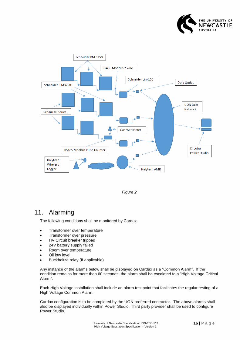
Schneider Electric PM5350 & IEM3250 power meters, IME gas & water meter pulse counters, Schneider Electric Link 150 Modbus-Ethernet Gateways, Circutor Power Studio Scada Deluxe energy monitoring software application running on server in UON data centre. Daisy chained RS485 data cabling runs between meters to Link 150 gateway which has data cable connected to UON network. Power Studio software extracts meter data via IP & Modbus references and displays values graphically on GUI and displays graphs/reports/alarms of required information. Remote facilities require optic fibre connectivity back to UON data network via either media converter (single-multi port) OR small managed switch. Fibre at network end is patched direct into a spare fibre port of the switch. Gas & water meter pulses can be picked up in 3 different ways – i) wired into a PM5350 power meter digital input and configured as pulse ii) wired to a dedicated RS485 modbus pulse counter iii) collected via Halytech AMR base station with remote water-gas meter pulse wired to Halytech battery wireless logger. Gas meter pulses also require an intrinsic safety barrier (Pepperl & Fuchs or equal) between gas meter and pulse counter (unless Halytech wireless). Modbus addressing is set per substation to reflect substation reference – eg Meter 1 at Sub 5 is set to Modbus address 51. Baud rate 9600-8-N. Figure 2 illustrates UON EMS network topology.
16 | P a g e University of Newcastle Specification UON-ESS-113 High Voltage Substation Specification – Version 1
Figure 2
11. Alarming
The following conditions shall be monitored by Cardax.
Transformer over temperature
Transformer over pressure
HV Circuit breaker tripped
24V battery supply failed
Room over temperature.
Oil low level.
Buckholtze relay (If applicable) Any instance of the alarms below shall be displayed on Cardax as a “Common Alarm”. If the condition remains for more than 60 seconds, the alarm shall be escalated to a “High Voltage Critical Alarm”. Each High Voltage installation shall include an alarm test point that facilitates the regular testing of a High Voltage Common Alarm. Cardax configuration is to be completed by the UON preferred contractor. The above alarms shall also be displayed individually within Power Studio. Third party provider shall be used to configure Power Studio.
17 | P a g e University of Newcastle Specification UON-ESS-113 High Voltage Substation Specification – Version 1
12. Ventilation
The substation shall be pressurized. The Intake fan shall be controlled by a Variable Speed Drive. Speed shall be controlled base on room temperature. Ventilation fan shall be initiated at 25 and turn off at 20 Degrees. The air intake filter shall be pleated cardboard and disposable. The filter shall be changeable from the exterior of the substation using a ladder on flat even ground. Access to the filter shall be through a hinged door with SK lock, no tools shall be required when changing the filter. The air relief vents shall utilize a pleated cardboard disposable Pre Filter. The filter shall be changeable from the exterior of the substation using a ladder on flat even ground. Access to the filter shall be through a hinged door with SK lock, no tools shall be required when changing the filter. Relief vents shall have manually adjustable louvers. Intumescent fire dampers shall be used.
13. Earthing
The earthing system must comply with the requirements of NS116 Design Standards for Distribution Equipment Earthing and NS113 Site Selection and Construction Design Requirement for Chamber Substations. If an existing earthing system is to be reused verification of compliance to relevant standards are to be presented to the UON representative prior to commencing work. All cable entry ducts (including both used and unused ducts) are to be sealed to prevent water entering the substation or spilled oil leaving the substation.
14. Ancillary Equipment
The substation shall also include a 24Vdc battery backup power supply to the High Voltage Circuit breakers. The batteries shall allow autonomous operation for a minimum of 24 hours. The battery charger controls/interface shall be at a height of at least one meter from the floor to allow access by the user.
15. Testing
On completion of the electrical installation works, the installation contractor shall provide certification in accordance with statutory authority (Ausgrid) requirements. This certification shall confirm that all works have been inspected and tested and comply with regulations. Copies of the compliance certification shall be included in the as installed documents. Testing shall include mandatory and optional tests outlined in Section 6 of AS/NZS 3000 and AS/NZS 3017, as applicable to the contract works. Certification shall be provided for those sections of the electrical installation, which require authority or independent inspections, which may be inspected and certified by the installation contractor. Any inspections or work shall only be undertaken by personnel with an approved Inspector’s/Electrician’s Licence for NSW. UON shall be given 24 hours’ notice to allow witnessing of the supply authority or statutory testing. Earth test results are to be presented to the UON representative prior to commencing work.
18 | P a g e University of Newcastle Specification UON-ESS-113 High Voltage Substation Specification – Version 1
16. Drawings and Documentation
Below are the electrical drawing and documentation requirements. Other non-electrical drawing and documentation requirements will be advised on a project by project basis.
Single line diagrams for all HV reticulation
Single line diagram for all LV reticulation
HV switchgear GA
LV Distribution boards and Main Switchboard GA
Transformer GA
PFC GA
Remote operating Panel GA
Battery Charger GA
HV switchgear Control Wiring Diagram
LV Distribution boards and Main Switchboards Control Wiring Diagram
Transformer Control Wiring Diagram
PFC Control Wiring Diagram
Remote operating Panel Control Wiring Diagram
Battery Charger Control Wiring Diagram
Lighting Layout
Small Power layout
Earth Grid layout and termination diagram
Communication drawings for all data connections including equipment interface
Service trench arrangements
Substation equipment layout
Critical/Common alarm wiring including test points
Lightning protection drawings
Wiring diagram, complete with numbered cores, for all control wiring
GA for all floor areas and showing equipment layout
Updated GIS showing all underground services
Electronic copy of all legends
All CB settings
Equipment manuals for all equipment
17. Defect Liability Period
The minimum Defect Liability Period for the project shall be twelve months. The installation contractor shall be responsible for managing all warranty replacement of panels/inverters OR defect recalls for components not meeting Australian requirements.
18. Miscellaneous
Once the works are complete, the area is to be cleaned of all redundant-loose-spare components, construction debris and packing materials.