Embed Size (px)
Citation preview

High-power magnetron transmitter as an RF source for superconducting linear accelerators
Grigory Kazakevich*, Rolland Johnson, Gene Flanagan, Frank Marhauser,
Muons, Inc., Batavia, 60510 IL, USA
Vyacheslav Yakovlev, Brian Chase, Valeri Lebedev, Sergei Nagaitsev, Ralph Pasquinelli, Nikolay Solyak, Kenneth Quinn, and Daniel Wolff,
Fermilab, Batavia, 60510 IL, USA
Viatcheslav Pavlov, Budker Institute of Nuclear Physics (BINP), Novosibirsk, 630090, Russia
A concept of a high-power magnetron transmitter based on the vector addition of signals of two
injection-locked Continuous Wave (CW) magnetrons, intended to operate within a fast and precise control loop in phase and amplitude, is presented. This transmitter is proposed to drive Superconducting RF (SRF) cavities for intensity-frontier GeV-scale proton/ion linacs, such as the Fermilab Project X 3 GeV CW proton linac or linacs for Accelerator Driven System (ADS) projects. The transmitter consists of two 2-cascade injection-locked magnetrons with outputs combined by a 3-dB hybrid. In such a scheme the phase and power control are accomplished by management of the phase and the phase difference, respectively, in both injection-locked magnetrons, allowing a fast and precise control of phase and output power, required to individually drive the SRF cavities. The capability of the injection-locked magnetrons has been verified by measurements of the transfer function characteristics of single and 2-cascade magnetrons in the phase modulation domain and simulation of the closed-loop performance. At the ratio of locking input power to output power of ≥ -13 dB (in 2-cascade scheme per magnetron, respectively) we demonstrated a phase modulation bandwidth of over 1.0 MHz for injection-locked CW single magnetrons and a 2-cascade setup, respectively. The ability to accurately and rapidly control output power of the transmitter has been first experimentally verified with two CW injection-locked magnetrons, combined in power by a 3-dB 180 degrees hybrid. The measured transfer functions of the injection-locked magnetrons in the phase modulation domain and simulated phase control loop performance demonstrate the capability of the transmitter to suppress parasitic modulation of the accelerating field in the SRF cavities, caused by mechanical noises, low-frequency ripples of the magnetron power supplies, and phase perturbations from cavity beam loading and cavity dynamic tuning errors. The magnetron transmitter concept, the transmitter modelling, experimental tests of the transmitter active components utilizing CW, 1 kW, S-band magnetrons, operating in injection-locked mode with large pulse duration, are presented and discussed in this paper.
PACS codes: 29.20.Ej, 84.40.Fe, 84.70.+p
I. INTRODUCTION
State of the art intensity frontier GeV-scale proton or ion superconducting linacs require CW RF sources to power SRF cavities, keeping the accelerating voltage phase and amplitude deviations to less than 1 degree and 1% of nominal, respectively. The average RF power to feed, for example, an ILC-type SRF cavity, providing an energy gain of ~20 MeV/cavity for a 1-10 mA average beam current, is a few tens to a few hundreds of kW. The investment costs for a RF power system for large-
scale projects (e.g. Project-X, ADS facilities, etc.) are a significant fraction of the overall costs, if traditional RF sources as klystrons, Inductive Output Tubes (IOTs) or solid-state amplifiers are used. Utilization of MW-scale CW klystrons to power groups of the cavities can save costs to some extent, but in turn only allow a control of the vector sum of the accelerating voltage in the group. Accelerating voltage vector sum control has not been tested for driving SRF cavities for non-relativistic or weakly relativistic particles; it may be unacceptable for low-velocity particles since non-optimized values of phase and amplitude of the accelerating field in individual SRF cavities can cause emittance growth, [1], and may lead to beam losses.
*Current affiliation: Muons, Inc., 552 North Batavia Ave., Batavia, IL 60510 e-mail: [email protected]; [email protected]
FERMILAB-PUB-13-315-AD-TD

The CW magnetrons based on commercial prototypes are efficient and potentially less expensive than the above-listed RF sources, [2], thus utilization of the magnetron RF sources in the large-scale accelerator projects will provide significant reduction of capital cost, especially since the CW magnetrons with power of tens to hundreds kW are well within current manufacturing capabilities.
Mechanical oscillations of SRF cavities, including “microphonics” and oscillations caused by Lorentz-force, result in parasitic modulation of the accelerating field with the bandwidth in the order or wider than the bandwidth of the SRF cavity. For ILC-type SRF cavities, the modulation may have a bandwidth from tens to hundreds Hz. The modulation can be suppressed using electronic damping techniques based on a management of the amplitude of the accelerating field, [3-5].
Additional perturbations of the accelerating field in SRF cavities are caused by dynamic tuning errors and beam loading. To suppress these perturbations, phase control of the accelerating field is necessary.
Since the manufactured SRF cavities are not identical in mechanical and RF properties, these perturbations also vary from cavity to cavity. Instantaneous phases and amplitudes of the mechanical oscillations are random in each cavity; a simple concept to power multiple SRF cavities with phase-locked magnetrons, [6], is not applicable for the low-energy superconducting accelerators. The concept most applicable for the accelerators is the powering of each SRF cavity by an individual vector controlled RF source providing a control of phase and of power.
A proof-of-principle of the phase control of an injection-locked magnetron first has been demonstrated with computations and from measurements performed with the 2.5 MW, 2.8 GHz pulsed magnetron type MI-456A, locked by a frequency and phase modulated signal, [7-9]. The magnetron frequency and phase response has been numerically computed in the time domain, considering a transient process in the magnetron and considering the magnetron as an oscillator forced (locked) by a signal with varied frequency. Unlike the approach developed by R. Adler, [10], the technique modelling the transient process allows computation of the magnetron frequency (phase) response in time domain, considering variations of the frequency (phase) of an external signal (frequency pulling), which may lock the magnetron, and considering variation of amplitude of the magnetron current (frequency pushing). The measurements of the frequency (phase) response, [7-9], verified very good accuracy of the computation. Further analysis of the computed and measured magnetron response on the frequency and phase modulated locking signal, [11], demonstrated an acceptable linearity and small phase errors in the response. Measurements of the magnitude characteristic of the transfer function of injection-locked CW, S-band, 1 kW magnetrons performed in the presented work demonstrated a wide bandwidth for phase control. These measurements
and the presented analysis demonstrate that fast phase control of injection-locked magnetrons will appropriately satisfy the stability requirements of intensity-frontier superconducting linacs. Performed estimations and numerical modelling based on the transfer function measurements demonstrates that power line related phase modulation sidebands of the injection-locked magnetrons associated with phase pushing may be almost completely eliminated by closed loop feedback of the phase term in the Low Level RF (LLRF) controller. This closed loop also will suppress phase perturbations from cavity beam loading, cavity dynamic tuning errors and perturbations of the magnetron magnetic field induced by magnetron filament AC circuitry. The last effect was observed and studied in the presented work.
A fast power control of injection-locked magnetrons with power combining, first realized in this work, demonstrates the capability of the magnetrons for the vector control of the accelerating field in SRF cavities.
The experimental tests, measurements, and numerical modelling performed with injection-locked magnetrons demonstrates proof-of-principle of the proposed magnetron transmitter concept to provide the vector control necessary to suppress all known low-frequency parasitic modulation in SRF cavities. The modelling and tests are discussed in this paper.
II. A CONCEPT OF THE MAGNETRON TRANSMITTER CONTROLLED IN
PHASE AND POWER The proposed concept of high-power magnetron transmitter based on the injection-locked 2-cascade magnetrons, [12], is represented in Fig. 1.
FIG. 1. Concept of the high-power transmitter based on injection-locked magnetrons with control in power and phase.

This transmitter configuration allows for the wideband phase and magnitude control necessary for linacs RF vector regulation requirements. The transmitter consists of two groups of cascaded injection-locked magnetrons with outputs combined by a 3-dB hybrid. For phase management the phases at inputs of both 2-cascade magnetrons are controlled simultaneously, while the power management is provided by a control of phase difference at the inputs of the 2-cascade magnetrons. The 2-cascade injection-locked magnetrons composed from low-power and high-power magnetrons with series connection via circulators were proposed to use lower locking power (-35 to -25 dB, relative to the combined output power). This allows using hundreds Watts drivers for the transmitter with combined power of hundreds kW. It will decrease the capital cost of the solid-state drivers locking the 2-cascade magnetrons. The transmitter scheme is acceptable for a wide dynamic power range. The transmitter efficiency is determined in general by the dynamic range of output power when the difference in powers of the 2-cascade magnetrons is insignificant, [15].
III. TECHNIQUES TO STUDY AND TEST THE MAGNETRON
TRANSMITTER CONCEPT Proof-of-principle of the proposed CW magnetron transmitter based on the injection-locked tubes was demonstrated in experiments with S-band, CW, microwave oven magnetrons with output power of up to 1 kW. The magnetrons operated in pulsed mode with pulse duration of a few ms at low repetition rate. This allowed employing lower average power RF and High Voltage (HV) components. Moreover, such an operation of the magnetrons allowed verifying the particular applicability of the transmitter concept for pulsed linacs accelerating long trains of bunches. All features of the transmitter were experimentally studied and tested using two magnetrons that were chosen to be locked at the same frequency. The two magnetrons, tube types 2M219J and OM75P(31), with a difference in the free run frequencies of about 5.7 MHz at an output power of ~500 W, were used in the experiments. The magnetrons have dissimilar Volt-Amps characteristics, but they were powered by a single pulse modulator with partial discharge of a 200 F storage capacitor, commutated by a HTS 101-80-FI IGBT (Behlke) fast switch. The modulator provides simultaneous operation of the two magnetrons with RF power up to 1 kW, each. A compensated divider has been used to power the magnetron with lower anode voltage when both magnetrons operated simultaneously. The level of ripple seen by the magnetron is negligible in the modulator, however, the capacitor introduces a voltage droop of approximately 0.4% to the 5 ms pulse when the modulator is loaded by the two 1 kW
magnetrons. To protect the magnetrons and the modulator components from arcs the modulator has an interlock chain that rapidly interrupts the HV if the modulator load current exceeds 3.5 Amps. The HV modulator was powered by a HV switching power supply. Table I summarizes operating parameters of the modulator.
Table I: Operating parameters of the modulator.
Parameter Symbol Value Output voltage UOut -(1-5) kV Repetition rate frep 0.25 Hz Pulse duration tpulse 2.5 - 15 ms Output current IOut 0.3-1.0 A Short Circuit Interlock threshold
Ithres
3.5 A
The proposed transmitter features have been studied and tested using two modules with the magnetrons operating at the locking frequency of 2.469 GHz. Scheme of the magnetron module is depicted in Fig. 2.
FIG. 2. The magnetron experimental module in which a CW magnetron operates as an injection-locked (forced) oscillator.
Each of the magnetrons was mounted on a WR430 waveguide, coupled with a waveguide-coax adapter. The waveguide section and the adapter were numerically optimized in 3D by CST Microwave Studio to minimize the RF reflection (S11) at the operating frequency and thus to maximize the transmission (S21), that resulted in S11= -26.3 dB and S21 = -0.1 dB, respectively. It has been verified that each magnetron can be injection-locked (at the same frequency) when operated in pulsed mode, pre-excited by a CW TWT amplifier driven by a CW signal generator (N5181A Agilent synthesizer) as it is shown in Fig. 3, [11]. The setup was also used to measure intrapulse phase variations of the injection-locked magnetron, Fig. 4, relative to the synthesizer signal, which was used as a reference. The measurements were performed utilizing a phase detector, composed of a trombone-like phase shifter, φ, a double balanced mixer, and a Low Pass Filter (LPF). A calibrated directional coupler, 3-dB splitter/combiner (S/C) and power meter were used to measure the locking power, PLock, while the magnetron output power, POut, was measured by the E4445A spectrum analyser which is not shown in this setup. Measured levels of the locking and output magnetron power are denoted in Fig. 3.

FIG. 3. Experimental setup with the phase detector to measure phase variations of the injection-locked magnetron. S/C is a 3-dB splitter/combiner; ML is a matched load.
-1 0 1 2 3 4 5
-20
-10
0
10
-200
-100
0
100
kVV
2
0
-4
-2-50
0
50
0 100 15050Pha
se,
deg
ree
s
Time, s
B
A
3
2
1Zero
crossing
1 ms
Pha
se, d
egre
es
Time, ms
FIG. 4. A- phase variations of the injection-locked magnetron type 2M219J operating at pulse duration of 5 ms at POut/PLock =9.6 dB, trace 1, left vertical scale. Traces 2 and 3 show shapes of the AC line voltage, and the magnetron HV pulse, right vertical scales, 100 V/div. and 2 kV/div., respectively. Inset B shows zoomed, in time, the phase variation during first 150 s.
The curve 1, Fig. 4a, shows phase variations during the 5 ms pulse. Inset 4b shows the phase variations during the first 0.15 ms. Both the traces show the variations composed from a low frequency (less than few kHz) and a high-frequency (more than few tens kHz) components, respectively. The low-frequency components are regular and stable from pulse-to-pulse. They are phase perturbations resulting from transient processes in the injection-locked magnetron. The phase perturbations are caused in general by variation of the magnetron emission current and magnetron temperature at pulsed operation, alternative magnetic field induced by the magnetron filament circuitry (as it is shown below) and variation of the magnetron current associated with the discharge of the modulator storage capacitor. Note that the measurements of phase variations of the TWT amplifier driving the magnetrons do not indicate the low-frequency components. The high-frequency components are stochastic noise. Measured at the output of the injection-locked CW
duration and time of sampling (≤10 ms in
~ 10 s, Fig. 4B, at the rate of
be explained by phase pushing, resulting
f ≤5.3 degrees (peak-to-peak at t ≥ 50 s)
ron phase variation, trace 1,
the sensitivity of the injection-locked magnetron to the induced magnetic field distorting the
magnetron, the high-frequency phase noise magnitude of < 0.4 degrees (rms) in main part of the pulse (t ≥50 s) reflects the contribution of the CW TWT wide-band amplifier. The performed measurements indicate that the stochastic noise of the magnetron itself is very insignificant. Note that the pulsed operation of the magnetrons with limited pulse these experiments) does not allow accurate measurements of spectral density of the low-frequency phase perturbations. Only high frequency phase noise could be measured. For CW SRF systems, low frequency noise power spectral density is the main concern and can only be measured in CW mode. Notable phase variation at the leading edge of the modulator pulse during ofHV pulse rise of ≈5 kV/s may result from phase pushing caused by several phenomena: multipactoring in the magnetron cavity when the pulsed high voltage is applied or/and variation of emitting properties of the magnetron cathode caused by cleaning of the emitting surface by back-streaming electrons. The time scales for both processes match the measured phase variation time. Operation of an SRF cavity would not suffer from the measured phase variation due to large filling time (a few ms) of the cavity. The shape of the slow phase perturbations during the long pulse, trace 1, can from competing processes: an increase of the magnetron current, most likely, because of overheating of the cathode surface caused by bombardment with back-streaming electrons and a decrease of the magnetron current associated with a drop of the magnetron voltage resulted from discharge of the modulator storage capacitor. The latter process dominates in the second half of the pulse. The thermal distortion of the magnetron geometry at pulsed operation and a magnetic field, induced by the magnetron filament AC circuitry may also contribute to the phase variations. The traces presented in Fig. 4 show phase variations magnitude oat pulse duration of ≈5 ms for a single magnetron operating in injection-locked mode. Seen in Fig. 4, the synchronism between the distortions of the injection-locked magnetand the distortions of the AC line voltage, trace 2, indicates an influence of a magnetic field induced by the magnetron filament circuitry on the magnetron phase stability. This phenomenon was studied measuring the injection-locked magnetron phase variation magnitude (peak-to-peak) vs. the time shift, between the moment of zero crossing of the magnetron filament current and triggering of the modulator. The measured data with a polynomial fit, Fig. 5, demonstrates

magnetron magnetic field. The distortion was minimized by triggering the modulator with a 1 ms shift relative to the moment of zero crossing of the magnetron filament current, as shown in Fig. 4A. Note that all experiments described in the presented work were conducted at nominal magnetron filament voltage.
-1.5 -1.0 -0.5 0.0 0.5 1.0 1.5 2.0 2.55
10
15
20
Pea
k-to
-pea
k ph
ase
egre
es)
dist
urba
nces
(d
(ms)
FIG. 5. Phase variations of the injection-locked magnetron vs. the time shift measured at POut/PLock of 15.8 dB.
Measured peak-to-peak phase variations of the injection-locked magnetron type 2M219J vs. the ratio of output power to locking power, P /P , are shown in Fig. 6.Out Lock
20
12 13 14 15 16 17 18 190
10
Pea
k-to
-pea
k ph
ase
ees)
dist
urba
nces
(de
gr
POut
/PLock
(dB)
FIG. 6. Dependence of phase variation (peak-to-peak) of the injection-locked magnetron vs. the locking power measured at the output power of 505 ± 5 W.
r ~ 500 deg/A,
the measurements at the ratio POut/PLock of
-CASCADE MAGNETRON
, in which the first inje er-power magnetron
used for injection-locking of the second one with higher
t the pulse duration of ≈
tio POut/PLock ≈
The measurements were performed at the output power of 505±5 W. The phase pushing value of ~1.5 deg/1% oassociated with the magnetron current variation was evaluated from~ 16 dB.
IV. EXPERIMENTAL VERIFICATION OF THE 2
CONCEPT
Operation of the 2-cascade injection-locked magnetronction-locked, low
ispower, has been tested in the experimental setup, Fig. 7, [11], composed of the two magnetron modules connected in series via an attenuator. This provided injection-locking
in the second magnetron by the attenuated signal from the first injection-locked magnetron. Both of the injection-locked magnetrons were powered simultaneously by the modulator a5 ms. The first magnetron was injection-locked by the CW TWT amplifier, while the second magnetron was locked by the pulsed signal generated by the first injection-locked magnetron. The magnetron having lower anode voltage has been powered through the compensated divider. The output powers of the magnetrons denoted in Fig. 7 were measured by the E4445A spectrum analyser, which is not shown in this setup. Phase variations of the 2-cascade injection-locked magnetron were measured at various attenuator values in the range from 13 dB to 20 dB, [ibid.].
FIG. 7. Experimental setup to measure phase variation of the 2-cascade injection-locked magnetron.
Trace of the phase variation of the 2-cascade injection-locked magnetron setup measured at the ra30 dB, considering the attenuator value of 15 dB, is plotted in Fig. 8.
60
-1 0 1 2 3 4 5-60
-40
-20
0
20
40
-120
-80
-40
0
40
80
120V kV
-2
-6
-4
4
2
0
A
B0 50 100 150
-50
0
50
Pha
se, d
egre
es
Time, s
Zerocrossing
1 ms
4
3
2
1
Pha
se, d
egre
es
Time, ms
FIG. 8. A- phase variations of the 2-cascade injection-locked magnetron measured at pulse duration of ≈ 5 ms at
of the
the attenuator value of 15 dB, trace 1, left vertical scale. Trace 2 shows voltage in the AC line, right vertical scale, 40 V/div. Traces 3 and 4 show shapes of HV pulses applied to magnetron I and magnetron II, respectively, right scale, 2 kV/div. Inset B shows zoomed in time trace 1.
The measured trace 1 of phase variation of the 2-cascade injection-locked magnetron resembles traces
injection-locked single magnetrons, but the magnitude of the phase variation is larger because of locking of the second (output) magnetron by a phase modulated signal. Nevertheless, the plotted trace 1 clearly demonstrates that the 2-cascade magnetron was still operating in injection-locked mode. This demonstrates proof-of principle of the 2-cascade injection-locked magnetron. Faster droop of the phase trace at t ≥2.5 ms is caused by the phase pushing resulting from enlarged discharge of the modulator capacitor loaded by two magnetrons. Measured high-frequency noise magnitude at t ≥50 s is ≤ 0.7 degrees (rms) at the output power of ≈ 500 W. The
s been
measured phase trace 1, Fig. 8, demonstrates operation of the experimental setup of the 2-cascade injection-locked magnetron at a ratio of the output power to the locking power of ≈ 30 dB, considering the attenuator value. The phase response of the 2-cascade injection-locked magnetron assembly on the 180 degrees phase flip haevaluated using the setup shown in Fig. 7, [13]. The 180 degrees phase flip in the TWT drive signal is accomplished with a pulse generator and double balanced mixer on the TWT amplifier input. The measured transient process of the injection-locked magnetron response, Fig. 9, on the 180 degrees phase flip takes ~ 300 ns at the flip duration of ≈ 15 ns. The time of the response is ~750 periods of the magnetron oscillation.
0.10
-0.10
-0.05
0.00
0.05
4.03.02.01.0
Pha
se d
etec
tor
mag
nitu
de (
V)
Time (s)
FIG. 9. Response of the frequency-locked 2-cascade magnetron on the 180 degrees phase flip measured at ratio
ons. More
L VERIFICATION
A setu locked CW low-power magnetrons in static and dynamic regimes
ry the power combined at port “” of the 3-dB 180
dividual power of each magnetron.
shown in Fig. 10, were 17.6 dB
of the output power to locking power ≈27 dB; the interferometer calibration is ≈ 0.8 degrees/mV.
Plot shown in Fig. 9 indicates quite wide bandwidth in the phase response of the 2-cascade magnetraccurate measurements of the bandwidth of the phase control of the 2-cascade and single injection-locked magnetrons were performed using phase modulation technique described below.
V. EXPERIMENTAOF THE POWER CONTROL IN THE
PROPOSED TRANSMITTER
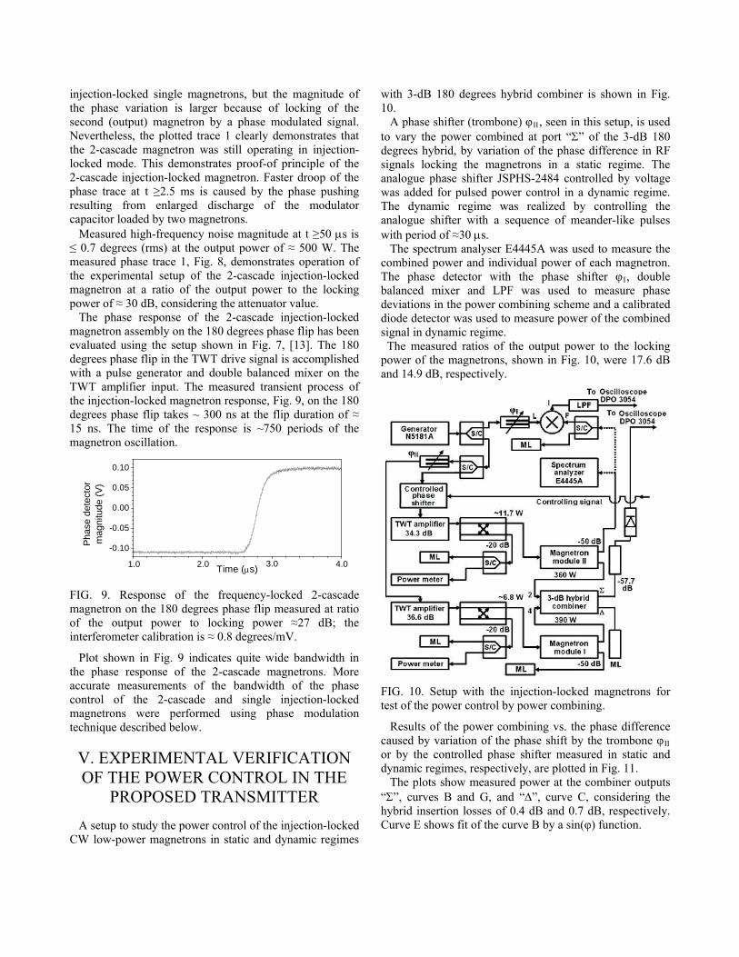
p to study the power control of the injection-
with 3-dB 180 degrees hybrid combiner is shown in Fig. 10. A phase shifter (trombone) φII, seen in this setup, is used to vadegrees hybrid, by variation of the phase difference in RF signals locking the magnetrons in a static regime. The analogue phase shifter JSPHS-2484 controlled by voltage was added for pulsed power control in a dynamic regime. The dynamic regime was realized by controlling the analogue shifter with a sequence of meander-like pulses with period of ≈30 s. The spectrum analyser E4445A was used to measure the combined power and inThe phase detector with the phase shifter φI, double balanced mixer and LPF was used to measure phase deviations in the power combining scheme and a calibrated diode detector was used to measure power of the combined signal in dynamic regime. The measured ratios of the output power to the locking power of the magnetrons, and 14.9 dB, respectively.
FIG. 10. Setup with the injection-locked magnetrons for test of the power control by power combining.
ombone φ
g the
Results of the power combining vs. the phase difference caused by variation of the phase shift by the tr II
or by the controlled phase shifter measured in static and dynamic regimes, respectively, are plotted in Fig. 11. The plots show measured power at the combiner outputs “”, curves B and G, and “”, curve C, considerinhybrid insertion losses of 0.4 dB and 0.7 dB, respectively. Curve E shows fit of the curve B by a sin(φ) function.

-1 0 1 2 3 4 5 60
100
200
300
400
500
600
Com
bin
ed p
ow
er,
W
Phase shift, , radians
B: P, static
C: P, static
E: Fit by sin() G: P
, dynamic
FIG. 11. Control of combined power of the injection-
e measured combined power, plots B and
locked magnetrons by the phase difference. Dots B and C present power variation at the combiner ports “” and “”, respectively, measured in static regime, Dots G show power variation at the combiner port “” measured in dynamic regime, Dots E show fit of the plots B and G by sin() function.
Agreement of thG with the fit trace, plot E, verifies that the utilized method of power control does not disturb injection-locking of the magnetrons. The plots B, G and E clearly indicate linearity and low phase errors in response of the injection-locked 1 kW, CW magnetrons at the phase control as it was observed earlier in operation of the 2.5 MW pulsed magnetron locked by frequency (phase)-modulated signal. Response of the injection-locked magnetrons with powercombining at the fast power control (in dynamic regime) is shown in Fig. 12.
280
0
40
80
120
160
200
240
0
2
4
6
8
10
12
14
C
B
A
806040200
700
500
300
100
200
400
600
0
Com
bine
d po
wer
, W
Con
trol
ling
volta
ge, V
Pha
se, d
egre
es
Time, s
FIG. 12. Dynamic power control of the injection-locked
se
f the analogue phase shifter is ≈50
gnetrons with
magnetrons with power combining. Trace A shows shape of signals controlling the phase shifter, first right scale. Trace B is the phase variation at the output of the magnetron II measured by the phase detector, left scale. Trace C shows power measured at port “” of the hybrid combiner at the phase shifter control, second right scale.
The measurements were performed at a modulator pulduration of ≈15 ms. Power was measured at the combiner port “”. The phase shifter II was tuned to get maximum power at the port “” when there was no signal controlling the phase shifter JSPHS-2484. The phase detector
trombone I was tuned to avoid saturation at measurements of the phase variation. Note the bandwidth okHz. The bandwidth of the power control of the combined magnetrons shown in plots B and C is limited by this value, but not by the bandwidth of the magnetron phase control, which is much wider as it is shown below. Phase variation of the injection-locked mathe power combining at modulator pulse duration of 5 ms is shown in Fig. 13.
-1 0 1 2 3 4 5-60
-40
-20
0
20
40
60 kVV
-120
-80
-40
80
40
0
-2
-4
4
-6
2
0
B
A
0 50 100 150
-100
-50
0
50
Pha
se, d
egre
es
Time, s
4
3
2
1
Zerocrossing
1 ms
Pha
se,
degr
ees
Time, ms
FIG. 13. A-trace 1 shows phase variations at the output “”
hown in Fig 13, the trombone φ
at t ≥ 50 s, Fig. 13, measured with the
Features of the control of the injection-locked
magnetrons were analyzed based on the earlier results of
of the hybrid, left vertical scale. Trace 2 shows the AC line voltage, right vertical scale, 40 V/div. Traces 3 and 4 shows pulsed voltages feeding the magnetrons I and II, respectively, right vertical scale, 2 kV/div. Inset B shows zoomed in time trace 1.
For the measurements s II
length, Fig. 10, has been chosen to provide maximum signal at the hybrid port “”, the phase shifter JSPHS-2484 control was OFF. Part of the trace calibrated phase detector, has a smooth shape with high-frequency phase noise magnitude of ≤ 0.5 degrees (rms). The phase trace resembles the traces of single magnetrons or 2-cascade magnetron. The phase variation magnitude coincides with an acceptable accuracy with the sum of magnitudes of the slow phase variations of the combined magnetrons. Larger phase variation at t ≥ 2.5 ms for magnetrons with power combining (similarly to phase variation of the 2-cascade magnetron) in comparison with a single magnetron results from larger phase pushing in the injection-locked magnetrons because of larger discharge of the modulator storage capacitor loaded by the two magnetrons.
VI. FEATURES OF THE PHASE CONTROL IN THE INJECTION-
LOCKED MAGNETRONS

modeling the transient process in the 2.8 GHz, 2.5 MW magnetron, [7-9], and study of the transfer function characteristic measured with the 1 kW CW injection-locked magnetrons at various setups. As it was shown in the earlier works, the approximate (abridged) equation describing transient process in the injection-locked magnetron considering frequency pulling and pushing can be written as:
.2 0
MMEM
FMEMLM
IYQ
V
Here: and are loaded and external magn
~~~1
2000 MM
MMM
QVi
Qdt
d
(1)
,LMQ EMQ etron
Q-factors, respectively, M0 is the eigenfrequency of the
magnetron cavity, MMLMM Q 002tan is
the detuning parameter, is the frequency (time-
dependent in common case) he locking signal, MVof t~
and
FMV~
are complex amplitudes of the oscillation in the
m ron cavity and in the wave locking the ma ron, ctively, MY0 [1/Ohm] is the external waveguide
conductance of the magnetron cavity, MI
agnetrespe
gnet
~ is the complex
amplitude of the first harmonic magnet current. Terms ron
FMEM
M VQ
~0 and
MMEM
M IYQ
~
2 0
0
describe frequency
d frequen spectively, pulling an cy pushing, re is the
angle between sum of the phasors FMV~
and I and the
phasor MVM
~
~,[17].
The uation (1) has been so num at measured and com
eq lved erically puted time-dependent magnitudes of the
phasors MV~
, FMV~
and MI ~
.
Compu ed and measured responses of the 2.5 MW magnetron on e freq ncy
t th ue (phase) modulated locking
signal are presented in Fig. 14, [11], plot G and D, respectively. Plot B shows time-dependent variation of the frequency of the signal with a power of -18 dB locking the magnetron.
0 1 2 3 4 5 6 7
G
D
B
2.8013
2.8014
2.8015
2.8016
Fre
quen
cy (
GH
z)
Time (s)
B: Locking frequency variationD: Measured frequency variationG: Computed frequency variation
FIG. 14. Variation of the computed (G), and measured frequency (D), of the 2.5 MW, 2.8 GHz pulsed magnetron
vs. variation of the locking frequency (B) in time domain.
The measurements show that time-to-lock of the magnetron does not exceed 2 s, including the time toestablish magnitude of the locking signal which is ~ 0.5 s. After the time-to-lock (t ≥2.5 s) the magnetron well repeats frequency variations of the forcing signal, i.e. it is locked by the frequency (phase)-modulated signal. Note the ripple in the computed trace G at t ≥ 2.5 s (when the magnetron was locked by the frequency-modulated signal) is produced from the data acquisition system measuring the magnetron voltage, current, amplitudes in forward and reflected waves and partially from limited statistics in simulation of the locking signal. The data acquisition system was not isolated well enough from the modulator grounding bus-bar, [9]. This caused noise in measurements and produced “ripple” in the computation. Regardless, the trace of the measurements of the magnetron frequency, curve D, at t ≥ 2.5 s is in good agreement with plot of the frequency-modulated locking signal, curve B. The injection-locked magnetron rms phase error was computed from the measured frequency variation, curve D, by integration over the filling time of the source of the locking signal. The obtained value of the phase error does not exceed 0.4 degrees. The plots shown in Fig. 14 also demonstrate an acceptable linearity of the frequency (phase) response of the injection-locked magnetron. Measurements of the phase response with the injection-locked 1 kW CW magnetrons at setups shown in Figs. 3, 7, 10 were performed using phase modulation with various values of phase in the synthesizer and the phase shifter. The performed measurements at the frequency of the phase modulation up to 100 kHz indicated quite good linearity in the magnetron phase response. This is in agreement with result obtained earlier with the 2.5 MW, 2.8 GHz pulsed magnetron. The bandwidth of the phase management of CW injection-locked magnetrons necessary for modelling of the
l lcontro oop has been determined by measurements of the magnitude transfer characteristic of the CW, S-band magnetrons with setups shown in Figs. 3 and 7. Phase modulation in the synthesizer with low magnitude (0.07 rad. ≈4 degrees) has been used for the measurements. The transfer function magnitude characteristics have been measured by the Agilent MXA N9020A Signal Analyzer in the phase modulation domain mode for various ratios POut/PLock and plotted in Fig. 15. The plotted transfer magnitude characteristics (rms values) were averaged over 8 pulses for the injection-
locked single 2M219J magnetron and the 2-cascade magnetron setup. Non-flatness of the synthesizer phase characteristic has been measured and taken into account.

10 100 1000-15
-10
-5
0 1 - 2 MHz
~ 300 kHz
Tra
nsfe
r ch
arac
teris
tics
ofa
phas
e co
ntro
l (dB
)
Frequency of phase modulation, fPM
, (kHz)
Single magnetron C: P
Out/P
Lock=15.3 dB
D: POut
/PLock
=12.3 dB E: P
Out/P
Lock=9.4 dB
2-cascade magnetron F: P
Out/P
Lock=28.1 dB
G: POut
/PLock
=27.1 dB H: P
Out/P
Lock=26.1 dB
FIG. 15. Transfer functions magnitude characteristics (rms values) of the phase control measured in phase modulation domain with single and 2-cascade injection-locked magnetrons for various ratios POut/PLock at POut ≈ 450 W.
The transfer characteristics of the magnetrons demonstrate wide bandwidth that allows for fast phase control of the magnetrons. The cutoff frequency of the phase modulation controlling the injection-locked magnetrons depends, as it is seen in Fig. 15, on ratio of the magnetron output power to power of the locking signal. The measured cutoff frequency of the phase modulation is ≈ 300 kHz at the locking power relative to the output power (per magnetron in the 2-cascade scheme) at about -14 dB or less, while at the locking power relative to the output power (per magnetron in the 2-cascade scheme) at more than about -13 dB, the cutoff frequency of the phase modulation is ≥ 1.0 MHz. Note that the measured transfer characteristics of a single injection-locked magnetron and the 2-cascade injection-locked magnetron setup do not demonstrate noticeable difference unlike the transfer characteristics of 1-cascade and 2-cascade conventional amplifiers. The transfer characteristics measured in the phase modulation domain, Fig. 15, implies that a Low Level RF controller may have a closed loop with a bandwidth of ≥100 kHz and will be able to suppress all expected system low-frequency perturbations, such as parasitic low frequency phase modulation (hundreds of Hz) and phase perturbations from SRF cavity beam loading, the cavity dynamic tuning errors and power supplies ripples. For example, the parasitic modulation caused by HV power supply ripple at frequency fr=120 Hz will be suppressed within a phase locking loop with integral gain I=1.2·107 rad./s, by ≈ 20·log(I/2·fr) ≈ 84 dB. Analysis of the equation (1) in steady-state allows
obtaining equation (2) for the phasor MV~
, [14]:
M
EM
LMFM
EM
LMM I
Q
QV
Q
QiV . (2) ~~2
)exp(cos~
In a steady state, as it is seen from (2), variation of the phase of the locking signal or/and variation of the
magnetron current amplitude leads to variation of phase of oscillation in the magnetron cavity. Thus the phase control or/and the control of the magnetron current can manage the phase of the injection-locked magnetron. However, the feedback loop involved in the magnetron current (in fact in the magnetron voltage) control will have narrower bandwidth limited by capacitive filter of the magnetron HV power supply. The narrower bandwidth of the closed feedback loop may reduce accuracy of the control and stability of the accelerating field in SRF cavities of linacs, if only the current control is used. The described analysis and the listed features verified in measurements with the injection-locked 2.5 MW pulsed magnetron and 1 kW CW magnetrons, and the results of measurements of the magnitude transfer characteristics performed in this work substantiate the utilization of injection-locked magnetrons with a fast phase control for intensity-frontier superconducting linacs. This is reflected in the proposed transmitter concept. Based on the measurements and evaluations, we expect to satisfy the requirements of the intensity-frontier superconducting linacs in stability of the phase and amplitude. Influence of the high-frequency phase noise of injection-locked magnetrons on the accelerating field in the SRF cavity has been numerically simulated with a simple model of a proportional-integral (PI) feedback phase loop around a superconducting cavity with a broad-band noise, Fig. 16. FIG. 16. Simplified model of a LLRF system controlling a superconducting cavity. The loop proportional gain, P, is 200, the integral gain, I, is 1.2·107 rad./s, the group delay is 2 s.
Shown in this model a 200 Hz half bandwidth low-pass filter models the cavity base-band response, a 400 kHz bandwidth noise source represents the phase noise of the magnetron and a 2 s delay represents all system group delay. The PI loop is setup with a proportional gain of 200 and integral gain 1.2·107 rad./s. The performed numerical modelling, Fig. 17, demonstrate that the broad band noise associated with the greatly exaggerated magnetron high-frequency noise is suppressed by the controller with the PI loop including the SRF cavity by ≈ 50 dB for peak-to-peak measurements.

FIG. 17. a: curve 1 is the 400 kHz bandwidth disturbance, curve 2 is cavity voltage, curve 3 is RF drive. Vertical scale is 10 MV/division. The inset b presents zoomed in ≈ 300 times (in vertical) trace of the cavity voltage, curve 2, in time domain. Vertical scale in the inset “b” is 0.1 MV/division.
Analysis of operation of injection-locked magnetrons and experiments with various setups of the magnetron RF sources confirmed the capability of a fast control of injection-locked magnetrons and substantiated operation of the magnetrons with a phase control loop. Described results allow design, simulation and optimization of the loops in accordance to requirements of the intensity-frontier superconducting linacs. The obtained experimental results and the performed numerical modelling indicated applicability of the proposed concept of the CW injection-locked magnetron transmitter with a fast vector control by a phase control loop to power SRF cavities of intensity-frontier linacs. Note that experiments described in [2, 15, 16] first verified operation of the injection-locked magnetron within a closed control loop.
VII. SUMMARY Presented are the results of a series of tests conducted on injection locked S-band, 1 kW microwave oven magnetrons. The motivation for the R&D is to control a pair of such magnetrons in a paraphase mode allowing fast amplitude and phase control at the tens to hundreds of kilowatts power level. Magnetrons are a very efficient source of high frequency RF power with a promising future for powering SRF cavities for particle accelerators. While this technique utilizes additional complexity, the cost savings of a successful system is significant in comparison to alternatives such as klystrons, IOTs, or solid-state amplifiers. Features of phase stability of the injection-locked magnetrons were studied with the 1 kW CW tubes operating in pulsed mode at various setups, modelling experimentally all active components of the proposed RF source based on magnetrons. The features are similar to these observed earlier in operation of 2.5 MW pulsed magnetron locked by frequency (phase)-modulated signal. What was shown is that injection locking of single and two cascaded magnetrons looks to be feasible, this being a necessary requirement for RF powers exceeding 10 kWatts
due to the low “locking gain” of 12-15 dB per magnetron. The fast power control in the above described injection-locked setup has been verified experimentally. The measured phase modulation bandwidth of over 1.0 MHz appears to be adequate for the application. The low-frequency phase perturbations less than 45 degrees measured in tests of all active the transmitter components can be suppressed by the phase control system. High-frequency phase noise of less than 1 degree (rms) measured in the tests of the proposed magnetron source is suitable for the intensity-frontier linacs requirements. Future testing will be with magnetrons operating in CW mode. We will perform measurements of low frequency phase disturbances, long-term stability, efficiency and demonstration of dynamic control of a paraphased CW system.
ACKNOWLEDGMENT This work has been supported by the US DOE grant DE-SC0006261 and collaboration Muons, Inc. – Fermilab. We thank Dr. Yu. Eidelman for useful discussion.
REFERENCES [1] Project X Reference Design Document:
http://projectx-docdb.fnal.gov/cgi- bin/ShowDocument?docid=776
[2] A.C. Dexter, G. Burt, R.G. Carter, and I. Tahir, H. Wang, K. Davis, and R. Rimmer, “First demonstration and performance of an injection-locked continuous wave magnetron to phase control a superconducting cavity”, PRST-AB, 14, 032001, 2011. [3] H. Padamsee, J. Knobloch, T. Hays, in “RF Superconductivity for Accelerators”, Wiley & Sons, Inc, 1998 [4] J. R. Delayen, “Electronic damping of microphonics in superconducting cavities”, PAC 01 Proceedings, Chicago, IL, USA, 2001. [5] T.L. Grimm, W. Hartung, T. Kandil, H. Khalil, J. Popielarski, C. Radcliffe, J. Vincent, R.C. York, “Measurement and control of microphonic in high loaded-Q superconducting RF cavities”, Linac 04 Proceedings, Lubeck, Germany, 2004. [6] T. Overett, D.B Remsen, E. Bowles, G.E. Thomas and R.E. Smith, „Phase locked magnetrons as accelerator RF sources“,12th IEEE Particle Accelerator Conference Proceedings, Washington, DC, USA, 1987. [7] G. Kazakevitch, Y.U Jeong, V.M. Pavlov, B.C. Lee, “Stabilization of the microtron-injector for a wide- band compact FIR FEL”, NIM A 528, (2004), 115- 119. [8] Grigory M. Kazakevich, Viatcheslav M. Pavlov,

Young Uk Jeong and Byung Cheol Lee, “Magnetron- Driven microtron injector of a terahertz free electron laser”, PRST-AB, 12, 040701, 2009. [9] Grigory M. Kazakevich, Viatcheslav M. Pavlov, Young Uk Jeong, Byung Cheol Lee, “Intrapulse Frequency stability of a magnetron frequency-locked through a wave reflected from an accelerating cavity”, NIM A 647, 10-16, 2011. [10] R. Adler, “A study of locking phenomena in oscillators,” Proceedings of the I.R.E. and Waves and Electrons, 34: 351–357, June 1946. [11] Grigory Kazakevich, Rolland Johnson, Gene Flanagan, Frank Marhauser, Mike Neubauer, Vyacheslav Yakovlev, Brian Chase, Sergei Nagaitsev, Ralph Pasquinelli, Nikolay Solyak, Vitali Tupikov, Daniel Wolff, “A two-stage injection-locked magnetron for accelerators with superconducting cavities”, IPAC12 Conference Proceedings, New Orleans, LA, 2012. [12] G. Kazakevich and V. Yakovlev,” Magnetron option for a pulse linac of the Project X”, Project X document 896, http://projectx-docdb.fnal.gov [13] Grigory Kazakevich, Gene Flanagan, Rolland Johnson, Frank Marhauser, Michael Neubauer, Todd Treado, Vyacheslav P. Yakovlev, Brian Chase, Sergei Nagaitsev, Ralph J. Pasquinelli, “A high- power 650 MHz CW magnetron transmitter for intensity frontier superconducting accelerators”, IPAC12 Proceedings, New Orleans, LA, 2012. [14] “Joint US-CERN-JAPAN international school on frontiers in accelerator technology”, 9-18 Sept. 1996, World Scientific, ISBN 981-02-3838-X. [15] H. Wang, K. Davis and R. Rimmer, I. Tahir, A.C. Dexter, G. Burt and R.G. Carter, “Use of an injection-locked magnetron to drive a superconducting cavity”, IPAC10 Proceedings, Kyoto, Japan, 2010. [16] I. Tahir, A. Dexter, R. Carter, “Noise performance of Frequency and Phase-Locked CW Magnetrons Operated as Current-Controlled Oscillators”, IEEE Trans on Electron Devices, V 52, No 9, 2096-2103, 2005.


![High-Power Magnetron Transmitter as an RF source for … · 2013-10-15 · simple concept to power multiple SRF cavities with phase-locked magnetrons, [6], is not applicable for the](https://img.dokumen.tips/doc/110x75/5e6aee839b68db753a7c3bb2/high-power-magnetron-transmitter-as-an-rf-source-for-2013-10-15-simple-concept.jpg)


![MAGNETRON RF SOURCES FOR STATE OF THE ART … · power combining to study wideband phase and power (amplitude) modulation in the transmitter, [6]. The wideband phase modulation of](https://img.dokumen.tips/doc/110x75/5f3e5644285889045536cde0/magnetron-rf-sources-for-state-of-the-art-power-combining-to-study-wideband-phase.jpg)