Embed Size (px)
Citation preview

High Performance 1553
© 2010 Data Device Corporation. All trademarks are the property of their respective owners.
High Performance 1553 White Paper
Page 1 Data Device Corporation
High Performance 1553
Abstract The U.S. Air Force is currently in the process of developing a revision to MIL-STD-1553 that will provide additional digital communication bandwidth beyond MIL-STD-1553B’s 1 Megabit per second (Mbps) rate. The proposed revision to MIL-STD-1553 (referred to as MIL-STD-1553C) is targeting 200 Mbps as a baseline data rate. This paper explores the feasibility of the U.S. Air Force’s proposed revision to MIL-STD-1553 based on studies conducted by Data Device Corporation (DDC). A combination of empirical and theoretical methods is used to determine if a MIL-STD-1553B network contains sufficient capacity to support the proposed 200 Mbps data rate. The results of DDC’s analysis is that for some MIL-STD-1553 buses there is sufficient bandwidth to implement a broadband system in which legacy 1 Mbps 1553B waveforms could coexist with new 200 Mbps waveforms, thus providing an incremental high speed communication channel to existing MIL-STD-1553 buses.
Keywords: MIL-STD-1553, avionics, military, data bus, high speed, broadband, capacity
Introduction MIL-STD-1553 is a robust serial data bus that has served as the primary command and control data network on board military aircraft for the last three decades. MIL-STD-1553’s characteristics of high reliability, high availability, fault tolerance, and highly interoperable have made it the data bus of choice for avionics systems. MIL-STD-1553 is still well suited for a large number of avionics applications; however, there are emerging requirements for high speed communication beyond MIL-STD-1553’s 1 Mbps rate.
Traditional avionics system have been implemented based on what is referred to as a federated architecture which consists of a series of independent subsystems which are interconnected with a fairly low speed command and control network (i.e. MIL-STD-1553). Information is processed with each subsystem and the results of the processed data are shared with other subsystems on an as needed basis. In general the amount of data passed between subsystems had been relatively low.
The advent of network enabled warfare and the increased desire to fuse sensor data from multiple sources (including off board data from other platforms or UAVs) is increasing the demand for high speed communication between subsystems on aircraft. Satisfying this demand for higher bandwidth communication on existing aircraft requires that either new cabling is installed or higher data rates are run over existing cabling. The implementation of new high speed interfaces becomes an economic tradeoff between the costs of adding additional cabling and associated electronics versus the cost of updating the existing electronics to increase the data rates on the existing MIL-STD-1553 buses. The US Air Force has estimated that it would cost approximately one million dollars to rewire a fighter aircraft to supplement or replace the MIL-STD-1553 cabling1.
The U.S. Air Force is currently engaged in the development of a revision to MIL-STD-1553 (from Rev B to Rev C) for the purpose of adding a new high bandwidth waveform that will provide 200 Mbps (or higher) bandwidth on existing 1553 buses,

High Performance 1553 White Paper
Page 2 Data Device Corporation
such that it will not interfere with legacy 1553 communication. This paper presents the results of testing conducted by DDC that support the feasibility of the U.S. Air Force’s goal of expanding the bandwidth of MIL-STD-1553.
MIL-STD-1553 Infrastructure
MIL-STD-1553 Network MIL-STD-1553 specifies a multi-drop linear time division multiplexed data bus (refer to Figure 1)2. The topology of a MIL-STD-1553 bus consists of a main transmission line that is terminated at both ends with a resistive load equal to the characteristic impedance (defined to be in the range of 70 to 85 ohms). Each terminal contains a transformer for the purpose of providing galvanic isolation. A terminal may be connected to the main bus using either a direct or transformer coupled connection. Direct coupled connections require that the terminal include a pair of fault isolation resistors in series with the isolation transformer. Transformer coupled connections utilize a bus coupler which contains an impedance matching transformer in addition to a pair of isolation resistors. The vast majority of 1553 implementations utilize transformer coupling. MIL-STD-1553B Notice 2 states “for Army and Air Force systems, only transformer coupled stub connections shall be used”3.
Figure 1. Transmit data path from a transmitting to a receiving 1553 terminal
The signal path of interest is from a transmitting terminal to a receiving terminal. A transmitted waveform first travels down the stub cable to the first bus coupler, then passes through the bus coupler to the main bus. The signal then travels down the bus passing through several bus couplers until it reaches the receiving coupler The signal finally passes through the receive coupler and up the stub cable to the receiving terminal (refer to Figure 1). It has been shown in previous papers that the loss through the coupling transformers can be extremely high for signals beyond the MIL-STD- 1553 passband4.
High Performance 1553 White Paper
Page 3 Data Device Corporation
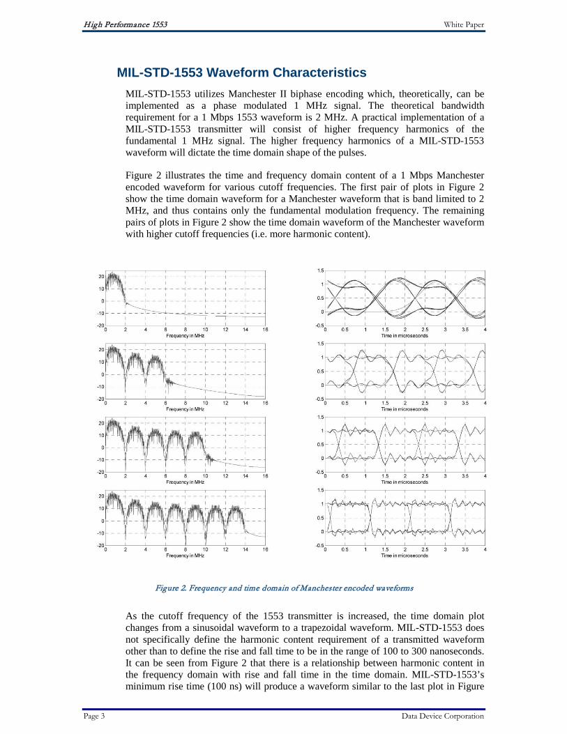
MIL-STD-1553 Waveform Characteristics MIL-STD-1553 utilizes Manchester II biphase encoding which, theoretically, can be implemented as a phase modulated 1 MHz signal. The theoretical bandwidth requirement for a 1 Mbps 1553 waveform is 2 MHz. A practical implementation of a MIL-STD-1553 transmitter will consist of higher frequency harmonics of the fundamental 1 MHz signal. The higher frequency harmonics of a MIL-STD-1553 waveform will dictate the time domain shape of the pulses.
Figure 2 illustrates the time and frequency domain content of a 1 Mbps Manchester encoded waveform for various cutoff frequencies. The first pair of plots in Figure 2 show the time domain waveform for a Manchester waveform that is band limited to 2 MHz, and thus contains only the fundamental modulation frequency. The remaining pairs of plots in Figure 2 show the time domain waveform of the Manchester waveform with higher cutoff frequencies (i.e. more harmonic content).
Figure 2. Frequency and time domain of Manchester encoded waveforms
As the cutoff frequency of the 1553 transmitter is increased, the time domain plot changes from a sinusoidal waveform to a trapezoidal waveform. MIL-STD-1553 does not specifically define the harmonic content requirement of a transmitted waveform other than to define the rise and fall time to be in the range of 100 to 300 nanoseconds. It can be seen from Figure 2 that there is a relationship between harmonic content in the frequency domain with rise and fall time in the time domain. MIL-STD-1553’s minimum rise time (100 ns) will produce a waveform similar to the last plot in Figure
High Performance 1553 White Paper
Page 4 Data Device Corporation
2, which contains significant harmonic content above the passband of the modulated signal. The range of rise and fall time was most likely selected to facilitate simpler transmitter designs while still meeting the intended performance requirements given the transmission line characteristics of the bus. The implication for a broadband system is that legacy MIL-STD-1553 waveforms may contain significant high frequency content.
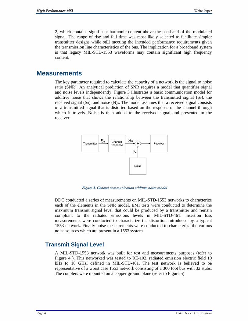
Measurements The key parameter required to calculate the capacity of a network is the signal to noise ratio (SNR). An analytical prediction of SNR requires a model that quantifies signal and noise levels independently. Figure 3 illustrates a basic communication model for additive noise that shows the relationship between the transmitted signal (ST), the received signal (SR), and noise (N)5. The model assumes that a received signal consists of a transmitted signal that is distorted based on the response of the channel through which it travels. Noise is then added to the received signal and presented to the receiver.
Figure 3. General communication additive noise model
DDC conducted a series of measurements on MIL-STD-1553 networks to characterize each of the elements in the SNR model. EMI tests were conducted to determine the maximum transmit signal level that could be produced by a transmitter and remain compliant to the radiated emissions levels in MIL-STD-461. Insertion loss measurements were conducted to characterize the distortion introduced by a typical 1553 network. Finally noise measurements were conducted to characterize the various noise sources which are present in a 1553 system.
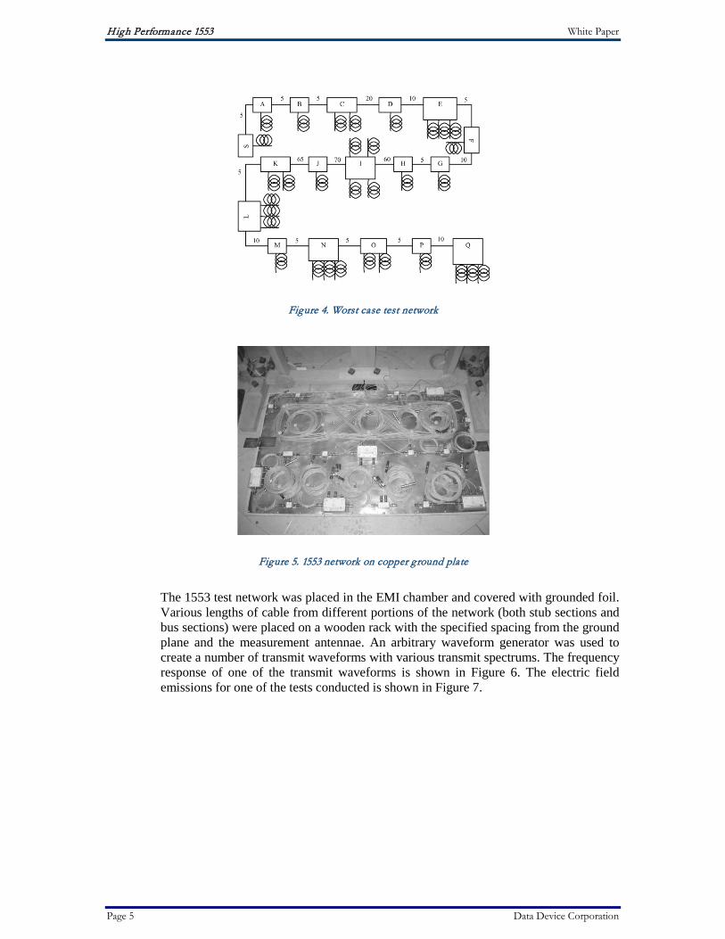
Transmit Signal Level A MIL-STD-1553 network was built for test and measurements purposes (refer to Figure 4 ). This networked was tested to RE-102, radiated emission electric field 10 kHz to 18 GHz, defined in MIL-STD-461. The test network is believed to be representative of a worst case 1553 network consisting of a 300 foot bus with 32 stubs. The couplers were mounted on a copper ground plane (refer to Figure 5).
High Performance 1553 White Paper
Page 5 Data Device Corporation
Figure 4. Worst case test network
Figure 5. 1553 network on copper ground plate
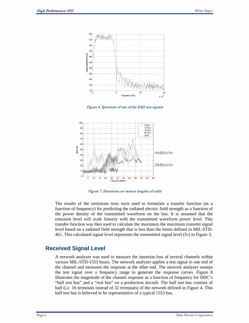
The 1553 test network was placed in the EMI chamber and covered with grounded foil. Various lengths of cable from different portions of the network (both stub sections and bus sections) were placed on a wooden rack with the specified spacing from the ground plane and the measurement antennae. An arbitrary waveform generator was used to create a number of transmit waveforms with various transmit spectrums. The frequency response of one of the transmit waveforms is shown in Figure 6. The electric field emissions for one of the tests conducted is shown in Figure 7.
High Performance 1553 White Paper
Page 6 Data Device Corporation
Figure 6. Spectrum of one of the EMI test signals
Figure 7. Emissions on various lengths of cable
The results of the emissions tests were used to formulate a transfer function (as a function of frequency) for predicting the radiated electric field strength as a function of the power density of the transmitted waveform on the bus. It is assumed that the emission level will scale linearly with the transmitted waveform power level. This transfer function was then used to calculate the maximum the maximum transmit signal level based on a radiated field strength that is less than the limits defined in MIL-STD-461. This calculated signal level represents the transmitted signal level (ST) in Figure 3.
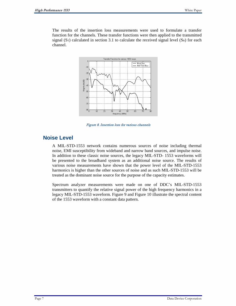
Received Signal Level A network analyzer was used to measure the insertion loss of several channels within various MIL-STD-1553 buses. The network analyzer applies a test signal to one end of the channel and measures the response at the other end. The network analyzer sweeps the test signal over a frequency range to generate the response curves. Figure 8 illustrates the magnitude of the channel response as a function of frequency for DDC’s “half test bus” and a “real bus” on a production aircraft. The half test bus consists of half (i.e. 16 terminals instead of 32 terminals) of the network defined in Figure 4. This half test bus is believed to be representative of a typical 1553 bus.
High Performance 1553 White Paper
Page 7 Data Device Corporation
The results of the insertion loss measurements were used to formulate a transfer function for the channels. These transfer functions were then applied to the transmitted signal (ST) calculated in section 3.1 to calculate the received signal level (SR) for each channel.
Figure 8. Insertion loss for various channels
Noise Level A MIL-STD-1553 network contains numerous sources of noise including thermal noise, EMI susceptibility from wideband and narrow band sources, and impulse noise. In addition to these classic noise sources, the legacy MIL-STD- 1553 waveforms will be presented to the broadband system as an additional noise source. The results of various noise measurements have shown that the power level of the MIL-STD-1553 harmonics is higher than the other sources of noise and as such MIL-STD-1553 will be treated as the dominant noise source for the purpose of the capacity estimates.
Spectrum analyzer measurements were made on one of DDC’s MIL-STD-1553 transmitters to quantify the relative signal power of the high frequency harmonics in a legacy MIL-STD-1553 waveform. Figure 9 and Figure 10 illustrate the spectral content of the 1553 waveform with a constant data pattern.

High Performance 1553 White Paper
Page 8 Data Device Corporation
Figure 9. Spectrum of 1 Mbps 1553 waveform with constant data (0 to 150 MHz scale)
Figure 10. Spectrum of 1 Mbps 1553 waveform with constant data (0 to 10 MHz scale)
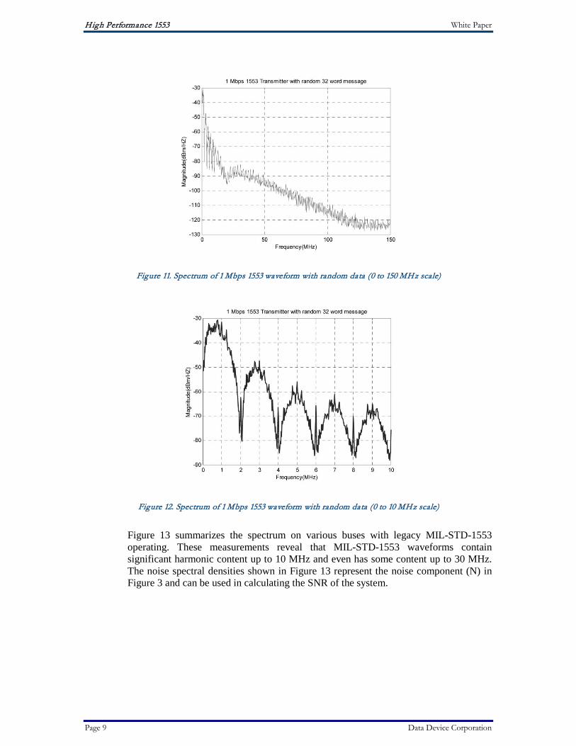
Figure 11 and Figure 12 illustrate the spectral content of a 1553 waveform with random data. Comparing the two 1553 transmit waveforms reveals that the spectrum of the 1553 waveform with constant data contains very narrow spikes with a relatively high peak while the spectrum of the waveform with random data produces a more normal distribution within each harmonic and results in a lower peak spectral power. Comparing Figure 10 and Figure 12 shows that the peak at 9 MHz is approximately 10 dB higher for a constant data pattern than the peak for a random data pattern. MILSTD- 1553 does not make use of a scrambler and as such there will be a mixture of constant data and some random data based on the nature of the data content.
High Performance 1553 White Paper
Page 9 Data Device Corporation
Figure 11. Spectrum of 1 Mbps 1553 waveform with random data (0 to 150 MHz scale)
Figure 12. Spectrum of 1 Mbps 1553 waveform with random data (0 to 10 MHz scale)
Figure 13 summarizes the spectrum on various buses with legacy MIL-STD-1553 operating. These measurements reveal that MIL-STD-1553 waveforms contain significant harmonic content up to 10 MHz and even has some content up to 30 MHz. The noise spectral densities shown in Figure 13 represent the noise component (N) in Figure 3 and can be used in calculating the SNR of the system.

High Performance 1553 White Paper
Page 10 Data Device Corporation
Figure 13. Various 1553 transmit spectrum measurements
Analysis The signal and noise levels of a broadband system were derived in the previous section. These values can now be used to calculate the overall signal to noise ratio of the system. The SNR needs to be calculated over a defined frequency band. For the purpose of this capacity estimate 30 MHz was chosen because the resulting signal to noise ratio was reasonable and a design using this bandwidth could be realized using existing state of the art technology. Shannon’s equation was used to predict the capacity of the measured channels (see Equation 1). This equation includes a factor, K, which represents the performance gap between an uncoded system and the Shannon limit. Selection of the value of K is based on experience with the achievable performance levels of various modulation techniques versus the theoretical Shannon limit.
Equation 1. Capacity Prediction
Capacity predictions were made based on the two sets of measurements. The first capacity estimate is based on the “Half test network” (a lab network consisting of 16 stubs as illustrated in Figure 4). The second capacity estimate is based on measurements made on a bus in real aircraft. The results of the capacity estimates are summarized in Table 1.

High Performance 1553 White Paper
Page 11 Data Device Corporation
Table 1. Capacity estimates for various network configurations Bus Configuration Bandwidth Shannon Capacity
Half test network 30 MHz 202 Mbps
Real bus 30 MHz 232 Mbps
Conclusion The measurements and analyses presented in this paper show, for the buses that were measured, that there is sufficient bandwidth within the channels to support in excess of 200 Mbps. The testing revealed that the channels are very lossy and that legacy MIL-STD-1553 waveforms produce a significantly high noise level in the frequency range above the 1553 passband. An implementation of a high bandwidth system will need to be able to compensate for distortion in the channel and will have to operate with a high noise level. It is believed that this type of high bandwidth system could achieve data rates over legacy MIL-STD-1553 buses in excess of 200 Mbps while operating concurrently with legacy MIL-STD-1553 waveforms.
High Performance 1553 White Paper
Page 12 Data Device Corporation
References 1. William Wilson, “High-performance and cost-effective avionics network upgrade solution and
approach”.
2. MIL-STD-1553 Designer’s Guide, Data Device Corporation, New York, 1998.
3. “MIL-STD-1553 Digital time division command/response multiple data bus”, revision B notice 2, paragraph 30.10.5, 8 September 1986.
4. Michael Hegarty, “Extending MIL-STD-1553 bandwidth: a study of impairments, EMI, and channel capacity”, Proceedings of SPIE, Volume 5443, pp. 288-299, 2004.
5. John Proakis, Digital Communications, pp. 11-12, The McGraw – Hill Companies, Inc., 2001.

High Performance 1553 White Paper
1105 Wilbur Place • Bohemia • New York 11716-2426 • 631-567-5600 • http://www.ddc-web.com
Michael Hegarty Principal Marketing Engineer Data Device Corporation
For more information, contact Michael Hegarty at 631-567-5600 ext. 7257 or [email protected]. Visit DDC on the web: www.ddc-web.com.
Data Device Corporation is recognized as an international leading supplier of high-reliability data interface products for military and commercial aerospace applications since 1964 and MIL-STD-1553 products for more than 25 years. DDC’s design and manufacturing facility is located in Bohemia, N.Y.
Data Device CorporationLeadership Built on Over 45 Years of Innovation
Data Device Corporation (DDC) is the world leader in the design and manufacture of high-reliability data bus products, motion control, and solid-state power controllers for aerospace, defense, and industrial automation applications. For more than 45 years, DDC has continuously advanced the state of high-reliability data communications and control technology for MIL-STD-1553, ARINC 429, Synchro/Resolver interface, and Solid-State Power Controllers with innovations that have minimized component size and weight while increasing performance. DDC offers a broad product line consisting of advanced data bus technology for Fibre Channel networks; MIL-STD-1553 and ARINC 429 Data Networking cards, components, and software; Synchro/Resolver interface components; and Solid-State Power Controllers and Motor Drives.
DDC is a leader in the development, design, and manufacture of highly reliable and innovative military data bus solutions. DDC's Data Networking Solutions include MIL-STD-1553, ARINC 429, and Fibre Channel. Each Interface is supported by a complete line of quality MIL-STD-1553 and ARINC 429 commercial, military, and COTS grade cards and components, as well as software that maintain compatibility between product generations. The Data Bus product line has been field proven for the military, commercial and aerospace markets.
DDC is also a global leader in Synchro/Resolver Solutions. We offer a broad line of Synchro/Resolver instrument-grade cards, including angle position indicators and simulators. Our Synchro/Resolver-to-Digital and Digital-to-Synchro/Resolver microelectronic components are the smallest, most accurate converters, and also serve as the building block for our card-level products. All of our Synchro/Resolver line is supported by software, designed to meet today's COTS/MOTS needs. The Synchro/Resolver line has been field proven for military and industrial applications, including radar, IR, and navigation systems, fire control, flight instrumentation/simulators, motor/motion feedback controls and drivers, and robotic systems.
As the world’s largest supplier of Solid-State Power Controllers (SSPCs) and Remote Power Controllers (RPCs), DDC was the first to offer commercial and fully-qualified MIL-PRF-38534 and Class K Space-level screening for these products. DDC’s complete line of SSPC and RPC boards and components support real-time digital status reporting and computer control, and are equipped with instant trip, and true I²T wire protection. The SSPC and RPC product line has been field proven for military markets, and are used in the Bradley fighting vehicles and M1A2 tank.
DDC is the premier manufacturer of hybrid motor drives and controllers for brush, 3-phase brushless, and induction motors operating from 28 Vdc to 270 Vdc requiring up to 18 kilowatts of power. Applications range from aircraft actuators for primary and secondary flight controls, jet or rocket engine thrust vector control, missile flight controls, to pumps, fans, solar arrays and momentum wheel control for space and satellite systems.
Product Families
Military | Commercial Aerospace | Space | Industrial
Data Bus | Synchro/Resolver | Power Controllers | Motor Drives
Certifications
Data Device Corporation is ISO 9001: 2008 and AS 9100, Rev. B certified.
DDC has also been granted certification by the Defense Supply Center Columbus (DSCC) for manufacturing Class D, G, H, and K hybrid products in accordance with MIL-PRF-38534, as well as ESA and NASA approved.
Industry documents used to support DDC's certifications and Quality system are: AS9001 OEM Certification, MIL-STD-883, ANSI/NCSL Z540-1, IPC-A-610, MIL-STD-202, JESD-22, and J-STD-020.

The information in this document is believed to be accurate; however, no responsibility is assumed by Data Device Corporation for its use, and no license or rights are granted by implication or otherwise in connection therewith. Specifications are subject to change without notice.
Outside the U.S. - Call 1-631-567-5700
United Kingdom: DDC U.K., LTD Mill Reef House, 9-14 Cheap Street, Newbury, Berkshire RG14 5DD, England Tel: +44 1635 811140 Fax: +44 1635 32264
France: DDC Electronique10 Rue Carle-Herbert 92400 Courbevoie France Tel: +33-1-41-16-3424 Fax: +33-1-41-16-3425
Germany: DDC Elektronik GmbHTriebstrasse 3, D-80993 München, Germany Tel: +49 (0) 89-15 00 12-11 Fax: +49 (0) 89-15 00 12-22
Japan: DDC Electronics K.K.Dai-ichi Magami Bldg, 8F, 1-5, Koraku 1-chome, Bunkyo-ku, Tokyo 112-0004, Japan Tel: 81-3-3814-7688 Fax: 81-3-3814-7689 Web site: www.ddcjapan.co.jp
Asia: Data Device Corporation - RO Registered in SingaporeBlk-327 Hougang Ave 5 #05-164 Singapore 530327 Tel: +65 6489 4801
Inside the U.S. - Call Toll-Free 1-800-DDC-5757
Headquarters and Main Plant105 Wilbur Place, Bohemia, NY 11716-2426 Tel: (631) 567-5600 Fax: (631) 567-7358 Toll-Free, Customer Service: 1-800-DDC-5757
Web site: www.ddc-web.com
DATA DEVICE CORPORATIONREGISTERED TO ISO 9001:2008REGISTERED TO AS9100:2004-01
FILE NO. A5976
REGISTERED FIRM
®U
The first choice for more than 45 years—DDC DDC is the world leader in the design and manufacture of high reliability data interface products, motion control, and solid-state power controllers for aerospace, defense, and industrial automation.
03/11