Embed Size (px)
Citation preview
422690 I
HIGH-EFFICIENCY UPFLOW FURNACE INSTALLER'S INFORMATION MANUAL
R T I F ICE ED
SIED GN
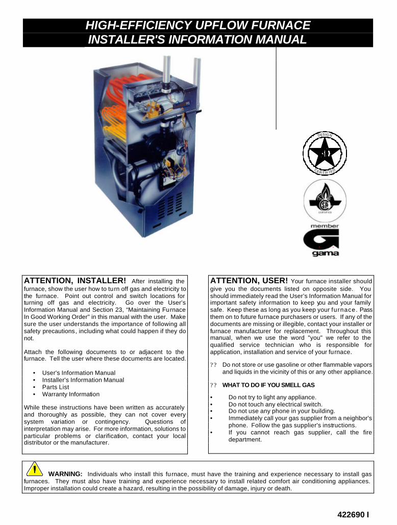
ATTENTION, INSTALLER! After installing the furnace, show the user how to turn off gas and electricity to the furnace. Point out control and switch locations for turning off gas and electricity. Go over the User’s Information Manual and Section 23, “Maintaining Furnace In Good Working Order" in this manual with the user. Make sure the user understands the importance of following all safety precautions, including what could happen if they do not.
Attach the following documents to or adjacent to the furnace. Tell the user where these documents are located. • User's Information Manual • Installer's Information Manual • Parts List • Warranty Information
While these instructions have been written as accurately and thoroughly as possible, they can not cover every system variation or contingency. Questions of interpretation may arise. For more information, solutions to particular problems or clarification, contact your local distributor or the manufacturer.
ATTENTION, USER! Your furnace installer should give you the documents listed on opposite side. You should immediately read the User’s Information Manual for important safety information to keep you and your family safe. Keep these as long as you keep your furnace. Pass them on to future furnace purchasers or users. If any of the documents are missing or illegible, contact your installer or furnace manufacturer for replacement. Throughout this manual, when we use the word "you" we refer to the qualified service technician who is responsible for application, installation and service of your furnace.
? ? Do not store or use gasoline or other flammable vapors and liquids in the vicinity of this or any other appliance.
? ? WHAT TO DO IF YOU SMELL GAS
• Do not try to light any appliance. • Do not touch any electrical switch. • Do not use any phone in your building. • Immediately call your gas supplier from a neighbor's phone. Follow the gas supplier's instructions. • If you cannot reach gas supplier, call the fire
department.
WARNING: Individuals who install this furnace, must have the training and experience necessary to install gas furnaces. They must also have training and experience necessary to install related comfort air conditioning appliances. Improper installation could create a hazard, resulting in the possibility of damage, injury or death.
Page 2 Installer’s Information Manual
TABLE OF CONTENTS
SECTION 1. IMPORTANT SAFETY RULES............................................................................................................. 2 SECTION 2. MEETING CODES .............................................................................................................................. 3 SECTION 3. DETERMINING BEST FURNACE LOCA TION ...................................................................................... 3 SECTION 4. PROVIDING VENTING AND COMBUSTION AIR.................................................................................. 5 SECTION 5. CONDENSATE DRAIN.......................................................................................................................14 SECTION 6. INSTALLING GAS PIPING..................................................................................................................14 SECTION 7. INSTALLING ELECTRICAL WIRING ...................................................................................................15 SECTION 8. SEQUENCE OF OPERATION ............................................................................................................17 SECTION 9. INSTALLING DUCT SYSTEM .............................................................................................................18 SECTION 10. SELECTING AND INSTALLING FILTER CABINETS ..........................................................................18 SECTION 11. CHECKS BEFORE STARTING FURNA CE ........................................................................................20 SECTION 12. GAS SUPPLY PRESSURE AND PILOT ADJUSTMENT.....................................................................20 SECTION 13. MANIFOLD PRESSURE ADJUSTMENT ...........................................................................................21 SECTION 14. CHECKING GAS INPUT RATE .........................................................................................................21 SECTION 15. DERATING FOR HIGH ALTITUDE ....................................................................................................22 SECTION 16. DETERMINING CORRECT ORIFICE SIZE ........................................................................................22 SECTION 17. CHANGING MAIN BURNER ORIFICES ............................................................................................23 SECTION 18. ADJUSTING BLOWER SPEED.........................................................................................................24 SECTION 19. MEASURING DUCT SYSTEM STATIC PRESSURE ..........................................................................24 SECTION 20. MEASURING AIR TEMPERATURE RISE..........................................................................................25 SECTION 21. CHECKING CONTROLS ..................................................................................................................25 SECTION 22. SETTING BLOWER TIMINGS...........................................................................................................26 SECTION 23. MAINTAINING FURNACE IN GOOD WORKING ORDER...................................................................26 SECTION 24. ACCESSORIES .............................................................................................................................27 SECTION 25. OTHER INFORMATION AND PUBLICATIONS ..................................................................................27
SECTION 1. IMPORTANT SAFETY RULES
To alert you to potential hazards, we use the signal words "WARNING" and "CAUTION" throughout this manual. "WARNING" alerts you to situations that could cause or result in serious injury or death. "CAUTION" alerts you to situations that could cause or result in minor or moderate injury or property damage. For a safe and reliable installation be sure to read and follow all warnings and cautions.
We also use the words "must" and "should" in this manual. "Must" is mandatory. "Should" is advisory.
WARNING: Read and follow the safety rules in this section and throughout this manual. Failure to do so could cause improper furnace operation, resulting in damage, injury or death.
Rule 1. Use only gas approved for use in this furnace, as indicated on furnace rating plate. Use only natural gas in furnaces designed for natural gas. Use only propane (LP) gas in furnaces designed for propane (LP) gas. Make sure furnace will operate properly on the gas type available to user. Do not use butane gas in this furnace.
WARNING: Use of a non-approved gas (such as butane) in this furnace could cause sooting or overheating of heat exchanger.
Rule 2. Do not install this furnace outdoors or in a mobile home, trailer or recreational vehicle. It is not design certified for these installations. This furnace is suitable for a home built on site or a manufactured home completed at the final s ite.
Rule 3. Air for combustion must not come from a corrosive or contaminated atmosphere. Make sure all combustion and ventilation air requirements are adhered to in addition to local codes and ordinances.
Rule 4. This furnace is not to be used for temporary heating of buildings or structures under construction.
Rule 5. Provide adequate combustion and ventilation air to space where furnace is being installed unless combustion air is provided directly through an inlet air pipe. Connect this furnace to an approved vent system--venting combustion products outdoors.
Rule 6. Check for gas leaks anytime work is done on gas supply line, furnace gas control, pilot and pilot line or main burner manifold.
Rule 7. Never test for gas leaks with an open flame. Use a commercial soap solution made specifically for leak detection to check all connections.
Installer’s Information Manual Page 3
Rule 8. Completely seal supply and return air ducts to furnace casing. Duct system must run to an area outside furnace room or closet. Seal duct work wherever it runs through walls, ceilings or floors of furnace room or closet.
SECTION 2. MEETING CODES
This furnace complies with American National Standard and National Standard of Canada for Gas Fired Central Furnaces, ANSI Z21.47 ? CAN/CGA-2.3. It is certified for operation with either natural gas or propane (LP) gas for indoor installation in a building constructed on site. It meets the requirement for a 100% shut-off gas control system.
Before installing this furnace, make sure you know all applicable codes. Be sure to consult local authorities having jurisdiction over furnaces for information on electrical wiring, gas piping and venting. The installation of this furnace must conform with local building codes or in the absence of local codes, with ANSI Z223.1, National Fuel Gas Code or CAN/CGA B149, Canadian Installation Codes.
Electrical wiring must conform with local building codes or in the absence of local codes, with the current National Electrical Code, ANSI/NFPA 70 or current Canadian Electrical Code, CSA C22.1.
SECTION 3. DETERMINING BEST FURNACE LOCATION
You may install this upflow furnace in an alcove, attic, basement, closet, garage or utility room. Do not install furnace in an area subject to freezing temperatures.
This furnace operates best when return-air temperature is between 55°F and 80°F. Do not install furnace in a location subject to continuous higher or lower temperatures. Continuous operation outside of this range may shorten furnace life.
WARNING: Do not install furnace in any other position other than upflow. Doing so could cause heat exchanger blockage and damage to heat exchanger.
Select a location that meets all requirements described in this manual for the following:
?? Safety ?? Minimum Clearances ?? Combustion and Ventilation Air ?? Venting ?? Duct System ?? Gas Piping ?? Electrical Wiring
Locate furnace as near to the center of the air distribution system as possible.
Provide ample space for servicing and cleaning. Location must allow 30 inches minimum front clearance for service.
WARNING: Some insulating materials are combustible. When a furnace is installed in an attic or other insulated space, keep all insulating materials at least 12 inches away from furnace and combustion air inlet. Failure to do so could cause a fire.
You may install furnace on non-combustible flooring or on wood flooring.
WARNING: Do not install furnace on carpeting, tile or other combustible material except wood flooring. Doing so could cause a fire.
Install furnace so all electrical components are protected from water.
Level furnace from front to back and from left to right within 1/4 inch. Furnace must be installed level for proper condensate drainage. Furnace will not operate if condensate does not drain.
When furnace is located within the heated space, exhaust fans can adversely affect its operation. Exhaust fans in kitchen, bathrooms, clothes dryers or anywhere within heated space, increase combustion air requirements of non-direct vented furnaces. This is because exhaust fans reduce the amount of combustion air available to the furnace. A fireplace also reduces amount of combustion air.
Sufficient air must be provided to ensure there will not be a negative pressure in furnace room or space. In addition, there must be a positive seal between furnace and return air duct to avoid pulling air from burner area.
When a cooling unit is installed with this furnace, the furnace must be installed parallel with or on the upstream side of the cooling unit to avoid condensation in furnace heat exchanger. With a parallel flow arrangement, the dampers or other means used to control flow of air must be adequate to prevent chilled air from entering the furnace and, if manually operated, must be provided with a means to prevent operation of either unit unless damper is in the full heat or cool position.
When furnace is in a residential garage, it must be installed so that pilot and main burners are located no less than 18 inches above the floor. Also, furnace should be protected from physical damage by vehicles.
When furnace is in a public garage, airplane hanger, or other building having hazardous atmosphere, install unit in accordance with recommended good practice requirements of the National Fire Protection Association, Inc. Consult local code authorities for additional location requirements.
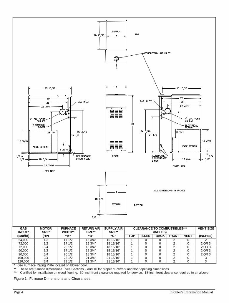
See Figure 1 for furnace dimensions and clearances.
Page 4 Installer’s Information Manual
GAS
INPUT* MOTOR
SIZE* FURNACE WIDTH**
RETURN AIR SIZE**
SUPPLY AIR SIZE**
CLEARANCE TO COMBUSTIBLES*** (INCHES)
VENT SIZE
(Btu/hr) (HP) “A” “B” “C” TOP SIDES BACK FRONT VENT (INCHES) 54,000 1/3 17 1/2 15 3/4” 15 15/16” 1 0 0 2 0 2 72,000 1/2 17 1/2 15 3/4” 15 15/16” 1 0 0 2 0 2 OR 3 72,000 3/4 20 1/2 18 3/4” 18 15/16” 1 0 0 2 0 2 OR 3 90,000 1/2 17 1/2 15 3/4” 15 15/16” 1 0 0 2 0 2 OR 3 90,000 3/4 20 1/2 18 3/4” 18 15/16” 1 0 0 2 0 2 OR 3 108,000 3/4 23 1/2 21 3/4” 21 15/16” 1 0 0 2 0 3 126,000 3/4 23 1/2 21 3/4” 21 15/16” 1 0 0 2 0 3
* See Furnace Rating Plate located on blower door. ** These are furnace dimensions. See Sections 9 and 10 for proper ductwork and floor opening dimensions. *** Certified for installation on wood flooring. 30-inch front clearance required for service. 18-inch front clearance required in an alcove.
Figure 1. Furnace Dimensions and Clearances.
Installer’s Information Manual Page 5
SECTION 4. PROVIDING VENTING AND COMBUSTION AIR
This furnace must be connected to a plastic venting system adequate to remove flue gases to the outside atmosphere. It must be vented in accordance with these instructions and local building codes.
The furnaces covered by this manual are design-certified as Category IV appliances. Category IV appliances operate with a positive vent static pressure and with a flue gas temperature that will produce significant condensate in the vent. The vent system for this furnace must be installed so as to prevent leakage of flue gases into the building. This furnace may be installed using either direct venting or non-direct venting.
WARNING: Do not connect this furnace to a vent system shared by any other appliance. Do not connect i t to any other type of vent system other than described by these instructions. Improper venting could allow combustion products to collect in building during use resulting in nausea or death by asphyxiation.
GENERAL VENTING GUIDELINES
?? Vent system and combustion air supply components must be constructed of schedule 40 PVC, PVC-DWV, SDR26, SDR 21 or ABS plastic pipe, fittings, sealants, and installation procedures that conform to the following ANSI/ASTM standards:
PVC ASTM D-1785
SDR26, SDR21 ASTM D-2241
PVC-DWV ASTM D-2665
PVC-DWV Cellular Core ASTM F-891
PVC Primer And Solvent Cement ASTM D-2564
ABS Pipe And Fittings ASTM D-2235
Procedure For Cementing Joints ASTM D-2855
?? All condensate formed in the vent must run back
toward furnace for proper drainage. Install vent pipe with no less than a 1/4 inch per foot slope from furnace to vent terminal.
?? Install vent pipe without dips or sags that may hold water. Support horizontal portions of vent pipe every 5 feet (3 feet for SDR-21 or SDR-26 pipe).
?? Protect vent from freezing. Long runs of vent pipe installed in an unconditioned space may require insulation to prevent freezing of condensate.
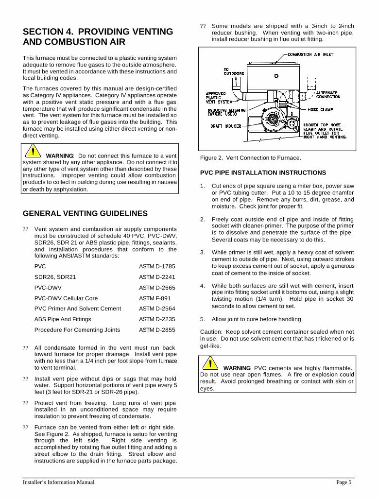
?? Furnace can be vented from either left or right side. See Figure 2. As shipped, furnace is setup for venting through the left side. Right side venting is accomplished by rotating flue outlet fitting and adding a street elbow to the drain fitting. Street elbow and instructions are supplied in the furnace parts package.
?? Some models are shipped with a 3-inch to 2-inch reducer bushing. When venting with two-inch pipe, install reducer bushing in flue outlet fitting.
Figure 2. Vent Connection to Furnace.
PVC PIPE INSTALLATION INSTRUCTIONS
1. Cut ends of pipe square using a miter box, power saw or PVC tubing cutter. Put a 10 to 15 degree chamfer on end of pipe. Remove any burrs, dirt, grease, and moisture. Check joint for proper fit.
2. Freely coat outside end of pipe and inside of fitting socket with cleaner-primer. The purpose of the primer is to dissolve and penetrate the surface of the pipe. Several coats may be necessary to do this.
3. While primer is still wet, apply a heavy coat of solvent cement to outside of pipe. Next, using outward strokes to keep excess cement out of socket, apply a generous coat of cement to the inside of socket.
4. While both surfaces are still wet with cement, insert pipe into fitting socket until it bottoms out, using a slight twisting motion (1/4 turn). Hold pipe in socket 30 seconds to allow cement to set.
5. Allow joint to cure before handling.
Caution: Keep solvent cement container sealed when not in use. Do not use solvent cement that has thickened or is gel-like.
WARNING: PVC cements are highly flammable. Do not use near open flames. A fire or explosion could result. Avoid prolonged breathing or contact with skin or eyes.
Page 6 Installer’s Information Manual
TERMINATION LOCATION AND CLEARANCES
Vent pipe and combustion-air-supply pipe (when direct vented) may terminate through a roof or through a sidewall. Roof termination has the advantages of better pipe protection and fewer condensate-damage concerns. Use the following guidelines when choosing a vent location:
?? Flue gases can be corrosive. When sidewall venting, protect walls with a corrosion resistant material. Also, terminate away from plants and shrubs.
?? Locate termination consistent with the National Fuel Gas Code, ANSI Z223.1/NFPA 54 or the CAN/CGA B149 Installation Codes.
?? Locate termination away from other air intake or exhaust vents such as dryer vents, other gas appliance vents, or plumbing vents. Allow at least 3 foot to any other vent.
?? Terminal must not be located above a walkway, driveway or within 10 feet of an adjacent building.
?? Do not locate termination underneath a veranda, porch, or deck.
IN THE UNITED STATES:
?? Allow a minimum clearance of 4 feet from electric meters, gas meters, regulators, and relief equipment.
?? When non-direct venting, terminal must be at least 4 feet below, or 4 feet horizontally from or one foot above any door, window or gravity air inlet into a building. Terminal must also be at least 3 feet above any forced-air inlet located within 10 feet horizontally.
?? When direct venting, vent terminal must be at least one foot from any opening through which flue gases could enter a building.
IN CANADA:
?? Allow 6 feet clearance to any mechanical air supply or service regulator vent and 6 feet horizontally to any gas meter, electric meter, or relief device.
?? Do not terminate above a meter/regulator assembly within 3 feet horizontally of the vertical center line of the regulator
?? Do not terminate within one foot (3 feet for 108,000 and 126,000 Btu models) of a window or door that can be opened, a non-mechanical-air-supply inlet, or the combustion-air inlet of any other appliance
EXISTING VENT CONSIDERATIONS
When a Category I furnace is removed or replaced, the old venting system may not be properly sized to vent the remaining appliance(s), for example, a gas water heater. An improperly sized venting system may promote the formation of condensate, leakage or spillage.
The following steps shall be followed with each appliance connected to the old venting system placed in operation, while any other appliances connected to the venting system are not in operation:
1. Seal any unused openings in the venting system;
2. Inspect the venting system for proper size and horizontal pitch, as required in the National Fuel Gas Code, ANSI Z223.1/NFPA 54 or the CAN/CGA B149 Installation Codes. Determine that there is no blockage or restriction, leakage, corrosion and other deficiencies which could cause an unsafe condition;
3. In so far as is practical, close all building doors and windows and all doors between space in which appliance(s) connected to the venting system are located and other spaces of building.
4. Close fireplace dampers.
5. Turn on clothes dryers and any appliance not connected to the venting system. Turn on any exhaust fans, such as range hoods and bathroom exhausts, so they shall operate at maximum speed. Do not operate a summer exhaust fan.
6. Follow the lighting instructions. Place the appliance being inspected in operation. Adjust thermostat so appliance shall operate continuously;
7. Test for drafthood equipped appliance spillage at the drafthood relief opening after 5 minutes of main burner operation. Use the flame of a match or candle;
8. After it has been determined that each appliance connected to the venting system properly vents when tested as outlined above, return doors, windows, exhaust fans, fireplace dampers and any other gas-burning appliance to their previous conditions of use;
9. If improper venting is observed during any of the above tests, the venting system must be corrected. Follow the National Fuel Gas Code, ANSI Z223.1/NFPA 54 or CAN/CGA B149 Installation Codes to correct improper vent operation. Any "common vent" re-sizing must approach minimum size determined using current venting tables.
DIRECT OR NON-DIRECT VENTING?
This furnace may be installed using either direct venting or non-direct venting.
A direct-vented furnace takes all air for combustion directly into the furnace through a pipe from outdoors. To direct vent this furnace you must install two pipes to the outdoors. One pipe supplies combustion air that the furnace needs to operate. The other pipe vents flue gases to the outdoors.
Use direct venting when indoor air may be contaminated with chemicals such as chlorine, fluorine, bromine or iodine. When these chemicals are burned with natural gas or propane gas, acids are produced that may decrease heat exchanger life. You should also consider direct venting when furnace is installed in a space with limited combustion and ventilation air. See “CONFINED SPACE
Installer’s Information Manual Page 7
INSTALLATION” under the “NON-DIRECT VENTING” instructions.
A non-direct vented furnace takes all air for combustion from the room in which furnace is installed. Non-direct venting requires only one pipe for venting the flue gases to the outdoors but you must make sure there is enough air for combustion and ventilation.
DIRECT VENTING INSTRUCTIONS (two pipe system)
DETERMINING VENT LENGTH
See Table 1 for maximum vent and combustion-air pipe length. Include any termination elbows when determining maximum allowable vent length. Minimum vent length is five feet with 0 elbows.
Table 1 shows the maximum allowable pipe lengths for direct vent systems depending on:
?? altitude (elevation) of the installation
?? gas input rating of furnace
?? diameter of the air and vent pipes
?? number of elbows
Note that some of the larger furnace models may require a high altitude pressure switch at elevations between 3000 and 6000 feet. For example, the table shows that the 126,000 Btu/hr model may need a high altitude pressure switch when installed at elevations between 3000 and 4000 feet. Above 4000 feet, this model requires a high altitude switch for all installations.
All furnace models require the high altitude pressure switch when installed at elevations above 6000 feet.
The high-altitude pressure switch is supplied with the LP Conversion Kit #4226000 and the Natural Gas Conversion Kit #4225600. These kits also contain the other components required for furnace installation at high elevations.
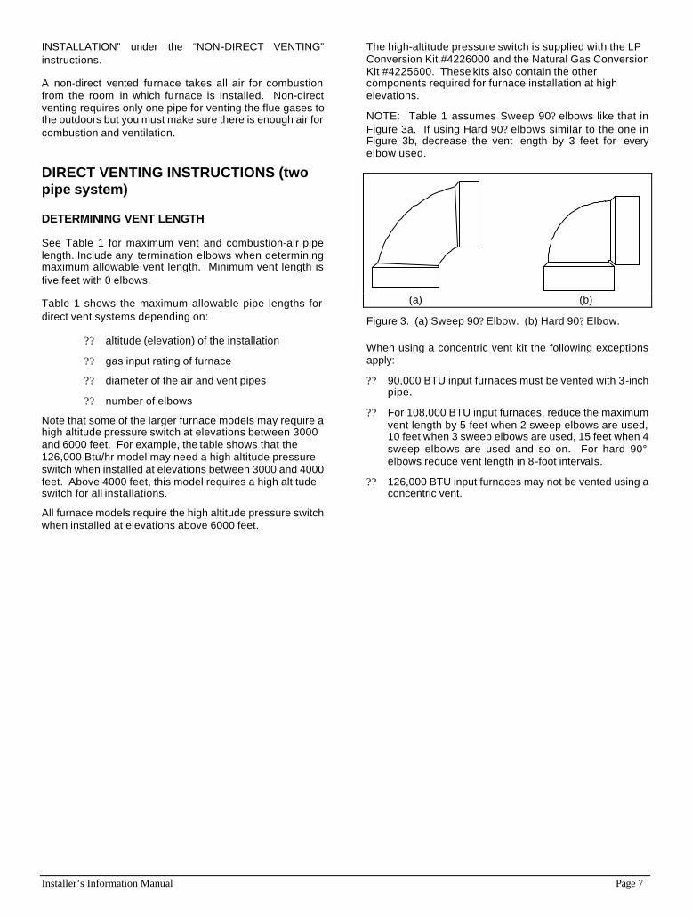
NOTE: Table 1 assumes Sweep 90? elbows like that in Figure 3a. If using Hard 90? elbows similar to the one in Figure 3b, decrease the vent length by 3 feet for every elbow used.
(a) (b)
Figure 3. (a) Sweep 90? Elbow. (b) Hard 90? Elbow.
When using a concentric vent kit the following exceptions apply:
?? 90,000 BTU input furnaces must be vented with 3-inch pipe.
?? For 108,000 BTU input furnaces, reduce the maximum vent length by 5 feet when 2 sweep elbows are used, 10 feet when 3 sweep elbows are used, 15 feet when 4 sweep elbows are used and so on. For hard 90° elbows reduce vent length in 8-foot intervals.
?? 126,000 BTU input furnaces may not be vented using a concentric vent.

Page 8 Installer’s Information Manual
Table 1. Maximum Pipe Length--Direct Vent
ALLOWABLE PIPE LENGTH (feet of each pipe)
ALTITUDE FURNACE PIPE NUMBER OF SWEEP ELBOWS (each pipe) (SEE NOTE 1) INPUT DIA. 1 2 3 4 5 6 7 8
54,000 2" 40 40 40 40 40 40 40 40 72,000 2" 40 40 37 33 30 27 23 20 72,000 3" 40 40 40 40 40 40 40 40
0'-1000' 90,000 2" 30 26 22 19 15 11 - - 90,000 3" 40 40 40 40 40 40 40 40 108,000 3" 40 40 40 40 40 40 40 40 126,000 3" 40 40 40 40 35 30 25 20 54,000 2" 40 40 40 40 40 40 40 40 72,000 2" 40 37 33 29 25 21 19 15 72,000 3" 40 40 40 40 40 40 40 40
1001'-2000' 90,000 2" 25 22 19 16 12 - - - 90,000 3" 40 40 40 40 40 40 40 40 108,000 3" 40 40 40 40 40 40 40 40 126,000 3" 40 38 33 28 22 16 11 - 54,000 2" 40 40 40 40 40 40 40 40 72,000 2" 35 33 29 25 21 17 13 - 72,000 3" 40 40 40 40 40 40 40 40
2001'-3000' 90,000 2" 22 19 16 14 - - - - 90,000 3" 40 40 40 40 40 40 40 40 108,000 3" 40 40 40 40 40 40 40 40 126,000 3" 35 30 25 20 15 10 - - 54,000 2" 40 40 40 40 40 40 40 40 72,000 2" 30 28 26 24 22 20 18 17 72,000 3" 40 40 40 40 40 40 40 40
3001'-4000' 90,000 2" 15 13 11 - - - - - 90,000 3" 40 40 40 40 40 40 40 40 108,000 3" 40 40 40 40 40 40 40 40 126,000 3" 30 25 20 15 10 - - - 126,000 3" 40 40 40 40 35 30 25 20 See Note 2 below. 54,000 2" 40 40 40 40 40 40 40 40 72,000 2" 26 22 17 14 12 - - - 72,000 3" 40 40 40 40 40 40 40 40
4001'-5000' 90,000 3" 40 40 40 40 40 40 40 40 108,000 3" 40 40 40 35 30 25 20 15 108,000 3" 40 40 40 40 40 40 40 40 See Note 2 below. 126,000 3" 40 40 40 40 35 30 25 20 54,000 2" 40 40 40 40 40 40 40 40 72,000 2" 21 18 14 11 - - - - 72,000 3" 40 40 40 40 40 40 40 40
5001'-6000' 90,000 3" 40 40 40 40 40 40 40 40 108,000 3" 40 35 30 25 20 15 10 - 108,000 3" 40 40 40 40 40 40 40 40 See Note 2 below. 126,000 3" 40 40 40 40 35 30 25 20 54,000 2" 40 40 40 40 40 40 40 40 72,000 2" 40 40 40 40 36 32 28 24 72,000 3" 40 40 40 40 40 40 40 40
6001'-7000' 90,000 3" 40 40 40 40 40 40 40 40 See Note 2 below. 108,000 3" 40 40 40 40 40 40 40 40 126,000 3" 40 40 40 40 35 30 25 20 54,000 2" 40 40 40 40 40 40 40 40 72,000 2" 40 40 40 37 35 32 28 24 72,000 3" 40 40 40 40 40 40 40 40
7001'-8000' 90,000 3" 40 40 40 40 40 40 40 40 See Note 2 below. 108,000 3" 40 40 40 40 40 40 40 40 126,000 3" 40 40 40 40 35 30 25 20 54,000 2" 40 40 40 40 40 40 40 40 72,000 2" 40 40 37 34 31 28 24 21 72,000 3" 40 40 40 40 40 40 40 40
8001'-9000' 90,000 3" 40 40 40 40 40 40 40 40 See Note 2 below. 108,000 3" 40 40 40 40 40 40 40 40 126,000 3" 40 40 40 35 30 25 20 15 54,000 2" 40 40 40 40 40 40 40 40 72,000 2" 40 37 35 31 27 24 21 18 72,000 3" 40 40 40 40 40 40 40 40
9001'-10000' 90,000 3" 40 40 40 40 40 40 40 40 See Note 2 below. 108,000 3" 40 40 40 40 40 40 40 40 126,000 3" 40 35 30 25 20 15 - -
NOTE 1: The table assumes the use of sweep elbows. If using hard 90? elbows, the vent length should be decreased an additional 3 feet for every elbow used.
NOTE 2: The shaded portions of the table require the high altitude pressure switch in order to operate the furnace at the listed vent lengths.
Installer’s Information Manual Page 9
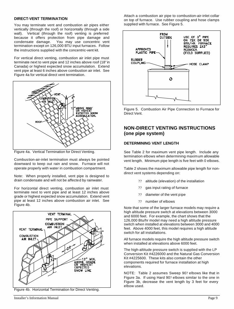
DIRECT-VENT TERMINATION
You may terminate vent and combustion air pipes either vertically (through the roof) or horizontally (through a side wall). Vertical (through the roof) venting is preferred because it offers protection from pipe damage and condensate damage. You may use concentric vent termination except on 126,000 BTU input furnaces. Follow the instructions supplied with the concentric-vent kit.
For vertical direct venting, combustion air inlet pipe must terminate next to vent pipe and 12 inches above roof (18” in Canada) or highest expected snow accumulation. Extend vent pipe at least 6 inches above combustion air inlet. See Figure 4a for vertical direct vent termination.
Figure 4a. Vertical Termination for Direct Venting.
Combustion-air-inlet termination must always be pointed downward to keep out rain and snow. Furnace will not operate properly with water in combustion compartment.
Note: When properly installed, vent pipe is designed to drain condensate and will not be affected by rainwater.
For horizontal direct venting, combustion air inlet must terminate next to vent pipe and at least 12 inches above grade or highest expected snow accumulation. Extend vent pipe at least 12 inches above combustion air inlet. See Figure 4b.
Figure 4b. Horizontal Termination for Direct Venting.
Attach a combustion air pipe to combustion-air-inlet collar on top of furnace. Use rubber coupling and hose clamps supplied with furnace. See Figure 5.
Figure 5. Combustion Air Pipe Connection to Furnace for Direct Vent.
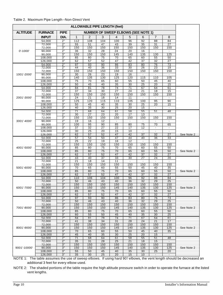
NON-DIRECT VENTING INSTRUCTIONS (one pipe system)
DETERMINING VENT LENGTH See Table 2 for maximum vent pipe length. Include any termination elbows when determining maximum allowable vent length. Minimum pipe length is five feet with 0 elbows.
Table 2 shows the maximum allowable pipe length for non-direct vent systems depending on:
?? altitude (elevation) of the installation
?? gas input rating of furnace
?? diameter of the vent pipe
?? number of elbows
Note that some of the larger furnace models may require a high altitude pressure switch at elevations between 3000 and 6000 feet. For example, the chart shows that the 126,000 Btu/hr model may need a high altitude pressure switch when installed at elevations between 3000 and 4000 feet. Above 4000 feet, this model requires a high altitude switch for all installations.
All furnace models require the high altitude pressure switch when installed at elevations above 6000 feet.
The high-altitude pressure switch is supplied with the LP Conversion Kit #4226000 and the Natural Gas Conversion Kit #4225600. These kits also contain the other components required for furnace installation at high elevations.
NOTE: Table 2 assumes Sweep 90? elbows like that in Figure 3a. If using Hard 90? elbows similar to the one in Figure 3b, decrease the vent length by 3 feet for every elbow used.
Page 10 Installer’s Information Manual
Table 2. Maximum Pipe Length--Non-Direct Vent
ALLOWABLE PIPE LENGTH (feet)
ALTITUDE FURNACE PIPE NUMBER OF SWEEP ELBOWS (SEE NOTE 1) INPUT DIA. 1 2 3 4 5 6 7 8
54,000 2" 112 108 104 100 96 92 88 84 72,000 2" 55 51 47 43 39 35 31 27 72,000 3" 150 150 150 150 150 150 150 150
0'-1000' 90,000 2" 36 32 28 24 20 16 - - 90,000 3" 150 150 150 145 140 135 130 125 108,000 3" 85 80 75 70 65 60 55 50 126,000 3" 62 57 52 47 42 37 32 27 54,000 2" 97 93 90 86 83 80 76 73 72,000 2" 44 40 36 33 30 26 23 19 72,000 3" 150 150 150 150 150 150 150 150
1001'-2000' 90,000 2" 30 26 23 19 16 - - - 90,000 3" 140 135 130 125 120 115 110 105 108,000 3" 75 70 65 60 55 50 45 40 126,000 3" 50 45 40 35 30 25 20 15 54,000 2" 84 81 78 74 71 67 64 61 72,000 2" 37 34 30 27 24 21 18 15 72,000 3" 150 150 150 150 150 150 150 150
2001'-3000' 90,000 2" 24 21 18 14 11 - - - 90,000 3" 125 120 115 110 105 100 95 90 108,000 3" 50 45 40 35 30 25 20 15 126,000 3" 40 35 30 25 20 15 - - 54,000 2" 71 68 64 61 58 55 51 48 72,000 2" 30 27 23 20 17 13 72,000 3" 150 150 150 150 150 150 150 150
3001'-4000' 90,000 2" 19 16 12 - - - - - 90,000 3" 100 95 90 85 80 75 70 65 108,000 3" 37 32 27 22 17 12 - - 126,000 3" 30 25 20 15 10 - - - 126,000 3" 62 57 52 47 42 37 32 27 See Note 2
below. 54,000 2" 57 54 50 47 44 40 36 33 72,000 2" 25 22 19 16 12 - - - 72,000 3" 150 150 150 150 150 150 150 150
4001'-5000' 90,000 3" 85 80 75 70 65 60 55 50 108,000 3" 85 80 75 70 65 60 55 50 See Note 2 126,000 3" 62 57 52 47 42 37 32 27 54,000 2" 43 40 37 33 30 27 24 20 72,000 2" 21 18 14 11 - - - - 72,000 3" 150 150 150 150 150 150 150 150
5001'-6000' 90,000 3" 70 65 60 55 50 45 40 35 108,000 3" 85 80 75 70 65 60 55 50 See Note 2 126,000 3" 62 57 52 47 42 37 32 27 54,000 2" 110 106 104 100 96 92 88 84 72,000 2" 50 46 43 40 36 32 29 25 72,000 3" 150 150 150 150 150 150 150 150
6001'-7000' 90,000 3" 150 150 150 145 140 135 130 125 See Note 2 108,000 3" 85 80 75 70 65 60 55 50 126,000 3" 62 57 52 47 42 37 32 27 54,000 2" 97 93 90 86 83 80 76 73 72,000 2" 50 46 43 40 36 32 29 25 72,000 3" 150 150 150 150 150 150 150 150
7001'-8000' 90,000 3" 150 150 150 145 140 135 130 125 See Note 2 108,000 3" 85 80 75 70 65 60 55 50 126,000 3" 60 55 50 45 40 35 30 25 54,000 2" 84 81 78 74 71 67 64 61 72,000 2" 41 38 34 31 28 24 21 17 72,000 3" 150 150 150 150 150 150 150 150
8001'-9000' 90,000 3" 150 150 150 145 140 135 130 125 See Note 2 108,000 3" 70 65 60 55 50 45 40 35 126,000 3" 45 40 35 30 25 20 15 54,000 2" 71 68 64 61 58 55 51 48 72,000 2" 35 31 28 25 21 18 15 - 72,000 3" 150 150 150 150 150 150 150 150
9001'-10000' 90,000 3" 150 150 150 145 140 135 130 125 See Note 2 108,000 3" 55 50 45 40 35 30 25 20 126,000 3" 35 30 25 20 15 10 - -
NOTE 1: The table assumes the use of sweep elbows. If using hard 90? elbows, the vent length should be decreased an additional 3 feet for every elbow used.
NOTE 2: The shaded portions of the table require the high altitude pressure switch in order to operate the furnace at the listed vent lengths.
Installer’s Information Manual Page 11
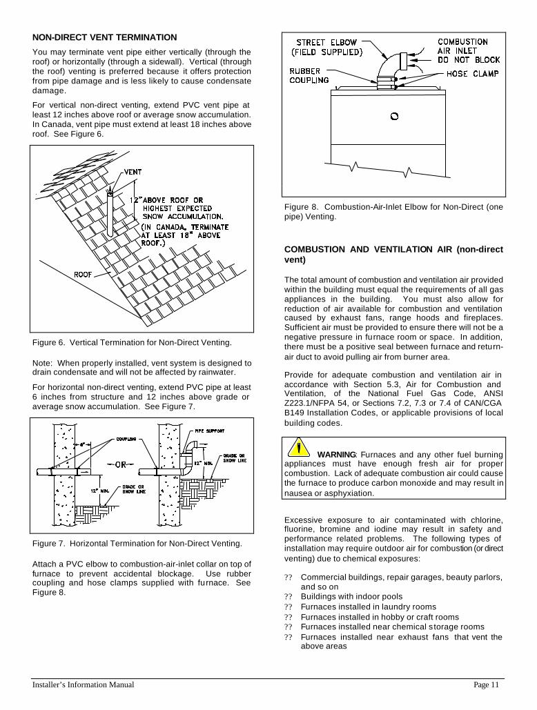
NON-DIRECT VENT TERMINATION
You may terminate vent pipe either vertically (through the roof) or horizontally (through a sidewall). Vertical (through the roof) venting is preferred because it offers protection from pipe damage and is less likely to cause condensate damage.
For vertical non-direct venting, extend PVC vent pipe at least 12 inches above roof or average snow accumulation. In Canada, vent pipe must extend at least 18 inches above roof. See Figure 6.
Figure 6. Vertical Termination for Non-Direct Venting.
Note: When properly installed, vent system is designed to drain condensate and will not be affected by rainwater.
For horizontal non-direct venting, extend PVC pipe at least 6 inches from structure and 12 inches above grade or average snow accumulation. See Figure 7.
Figure 7. Horizontal Termination for Non-Direct Venting.
Attach a PVC elbow to combustion-air-inlet collar on top of furnace to prevent accidental blockage. Use rubber coupling and hose clamps supplied with furnace. See Figure 8.
Figure 8. Combustion-Air-Inlet Elbow for Non-Direct (one pipe) Venting.
COMBUSTION AND VENTILATION AIR (non-direct vent)
The total amount of combustion and ventilation air provided within the building must equal the requirements of all gas appliances in the building. You must also allow for reduction of air available for combustion and ventilation caused by exhaust fans, range hoods and fireplaces. Sufficient air must be provided to ensure there will not be a negative pressure in furnace room or space. In addition, there must be a positive seal between furnace and return-air duct to avoid pulling air from burner area.
Provide for adequate combustion and ventilation air in accordance with Section 5.3, Air for Combustion and Ventilation, of the National Fuel Gas Code, ANSI Z223.1/NFPA 54, or Sections 7.2, 7.3 or 7.4 of CAN/CGA B149 Installation Codes, or applicable provisions of local building codes.
WARNING: Furnaces and any other fuel burning appliances must have enough fresh air for proper combustion. Lack of adequate combustion air could cause the furnace to produce carbon monoxide and may result in nausea or asphyxiation.
Excessive exposure to air contaminated with chlorine, fluorine, bromine and iodine may result in safety and performance related problems. The following types of installation may require outdoor air for combustion (or direct venting) due to chemical exposures:
?? Commercial buildings, repair garages, beauty parlors, and so on
?? Buildings with indoor pools ?? Furnaces installed in laundry rooms ?? Furnaces installed in hobby or craft rooms ?? Furnaces installed near chemical s torage rooms ?? Furnaces installed near exhaust fans that vent the
above areas
Page 12 Installer’s Information Manual
Exposure to the following substances in the combustion air supply may also require outdoor air for combustion:
?? Aerosols ?? Permanent wave solutions ?? Chlorinated waxes, bleaches and cleaners ?? Cat litter ?? Chlorine-based swimming pool chemicals ?? Cleaning solvents ?? Paint removers and varnishes ?? Adhesives ?? Anti-static fabric softeners ?? Most refrigerants
WARNING: Combustion air that contains chlorine, fluorine, bromine or iodine could cause corrosion in heat exchanger and may result in nausea or death by asphyxiation.
UNCONFINED SPACE INSTALLATION (non-direct vent)
The National Fuel Gas Code, ANSI Z223.1/NFPA 54 and CAN/CGA B149 Installation Codes do not require that you make special provisions for combustion and ventilation air when furnace is in an "unconfined space" and building is not of "unusually tight construction."
?? "Unconfined spaces" have a volume of at least 50 cubic feet per 1000 Btu per hour combined input rating of all appliances installed in the space. For example: a 100,000 Btu/hr furnace and a 40,000 Btu/hr water heater would require a volume of at least 140,000 X 50 ÷ 1,000 or 7,000 cubic feet.
?? "Unusually tight construction" means windows and doors are either tight fitting or are sealed construction and that walls are covered with a continuous, sealed vapor barrier and drywall or similar materials having sealed joints.
If you meet the volume requirements for unconfined space, the building is not of unusually tight construction and there are no airborne contaminants, as listed above, you may install this furnace without making special provisions for combustion and ventilation air. Otherwise, follow the instructions for "confined space installation" below or direct vent the furnace using two pipes.
CONFINED SPACE INSTALLATION (non-direct vent)
A non-direct vented furnace installed in a confined space must take combustion and ventilation air from an unconfined space within the building or from outdoors. However, if the building is of unusually tight construction all combustion air must come from outdoors. Also, if return air is taken directly from a hallway or space next to furnace that communicates with furnace spaces, all combustion air must come from outdoors.
WARNING: You must provide permanent air openings to a confined furnace installation space from another area as described below. Failure to do so could cause inadequate combustion and ventilation air and may result in nausea or death by asphyxiation.
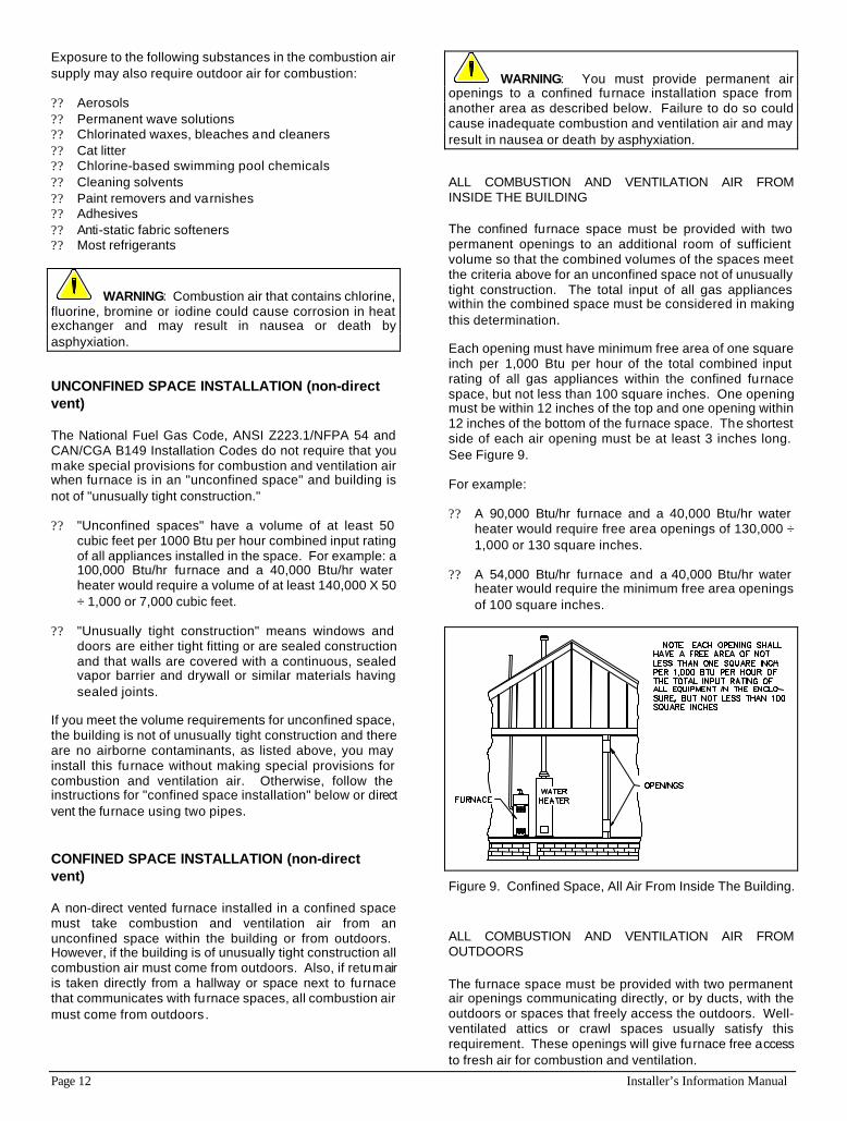
ALL COMBUSTION AND VENTILATION AIR FROM INSIDE THE BUILDING
The confined furnace space must be provided with two permanent openings to an additional room of sufficient volume so that the combined volumes of the spaces meet the criteria above for an unconfined space not of unusually tight construction. The total input of all gas appliances within the combined space must be considered in making this determination.
Each opening must have minimum free area of one square inch per 1,000 Btu per hour of the total combined input rating of all gas appliances within the confined furnace space, but not less than 100 square inches. One opening must be within 12 inches of the top and one opening within 12 inches of the bottom of the furnace space. The shortest side of each air opening must be at least 3 inches long. See Figure 9.
For example:
?? A 90,000 Btu/hr furnace and a 40,000 Btu/hr water heater would require free area openings of 130,000 ÷ 1,000 or 130 square inches.
?? A 54,000 Btu/hr furnace and a 40,000 Btu/hr water heater would require the minimum free area openings of 100 square inches.
Figure 9. Confined Space, All Air From Inside The Building.
ALL COMBUSTION AND VENTILATION AIR FROM OUTDOORS
The furnace space must be provided with two permanent air openings communicating directly, or by ducts, with the outdoors or spaces that freely access the outdoors. Well-ventilated attics or crawl spaces usually satisfy this requirement. These openings will give furnace free access to fresh air for combustion and ventilation.
Installer’s Information Manual Page 13
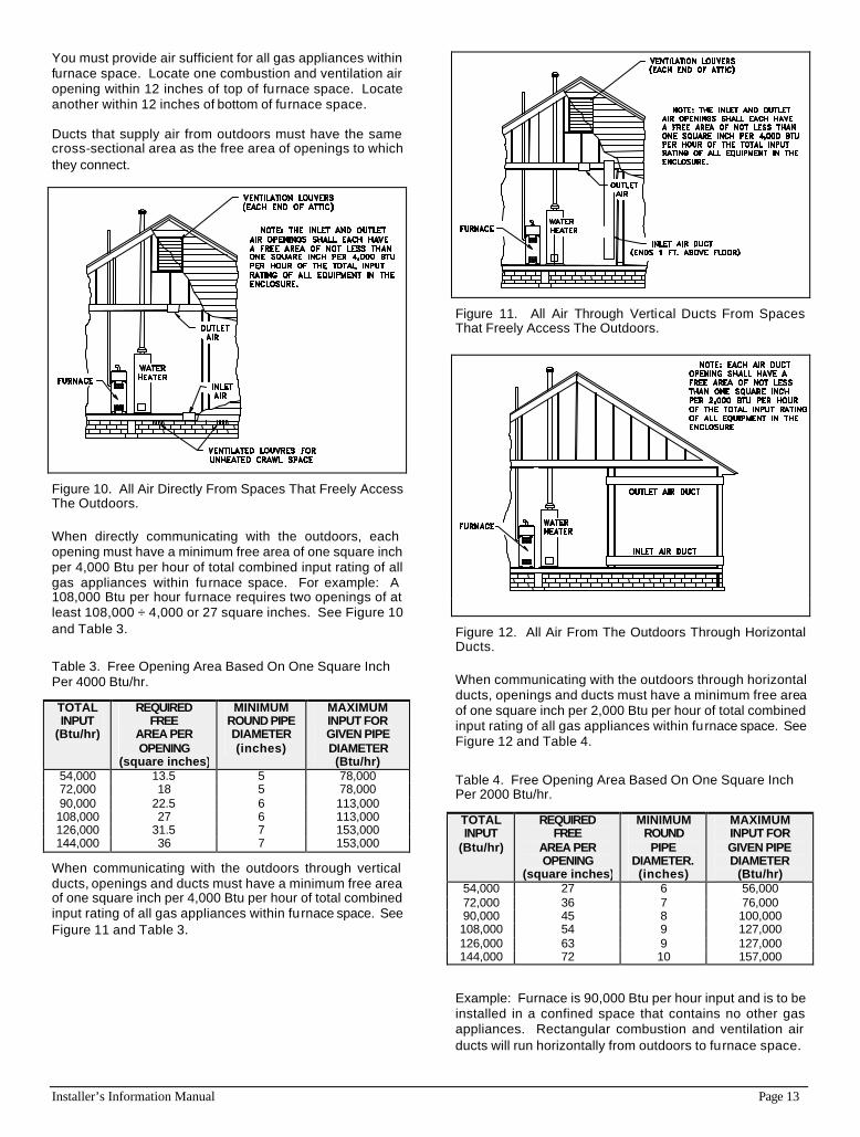
You must provide air sufficient for all gas appliances within furnace space. Locate one combustion and ventilation air opening within 12 inches of top of furnace space. Locate another within 12 inches of bottom of furnace space.
Ducts that supply air from outdoors must have the same cross-sectional area as the free area of openings to which they connect.
Figure 10. All Air Directly From Spaces That Freely Access The Outdoors.
When directly communicating with the outdoors, each opening must have a minimum free area of one square inch per 4,000 Btu per hour of total combined input rating of all gas appliances within furnace space. For example: A 108,000 Btu per hour furnace requires two openings of at least 108,000 ÷ 4,000 or 27 square inches. See Figure 10 and Table 3.
Table 3. Free Opening Area Based On One Square Inch Per 4000 Btu/hr.
TOTAL INPUT
(Btu/hr)
REQUIRED FREE
AREA PER OPENING
(square inches)
MINIMUM ROUND PIPE DIAMETER (inches)
MAXIMUM INPUT FOR GIVEN PIPE DIAMETER (Btu/hr)
54,000 13.5 5 78,000 72,000 18 5 78,000 90,000 22.5 6 113,000 108,000 27 6 113,000 126,000 31.5 7 153,000 144,000 36 7 153,000
When communicating with the outdoors through vertical ducts, openings and ducts must have a minimum free area of one square inch per 4,000 Btu per hour of total combined input rating of all gas appliances within furnace space. See Figure 11 and Table 3.
Figure 11. All Air Through Vertical Ducts From Spaces That Freely Access The Outdoors.
Figure 12. All Air From The Outdoors Through Horizontal Ducts.
When communicating with the outdoors through horizontal ducts, openings and ducts must have a minimum free area of one square inch per 2,000 Btu per hour of total combined input rating of all gas appliances within furnace space. See Figure 12 and Table 4.
Table 4. Free Opening Area Based On One Square Inch Per 2000 Btu/hr.
TOTAL INPUT
(Btu/hr)
REQUIRED FREE
AREA PER OPENING
(square inches)
MINIMUM ROUND PIPE
DIAMETER. (inches)
MAXIMUM INPUT FOR GIVEN PIPE DIAMETER
(Btu/hr) 54,000 27 6 56,000 72,000 36 7 76,000 90,000 45 8 100,000 108,000 54 9 127,000 126,000 63 9 127,000 144,000 72 10 157,000
Example: Furnace is 90,000 Btu per hour input and is to be installed in a confined space that contains no other gas appliances. Rectangular combustion and ventilation air ducts will run horizontally from outdoors to furnace space.
Page 14 Installer’s Information Manual
Calculate the free area required.
Because combustion and ventilation air ducts run horizontally, allow 2,000 Btu per hour.
Furnace input (Btu/hr) = Free area required 2,000 Btu/hr per square inch 90,000 = 45 square inches 2,000 Both of the ducts must have a minimum cross sectional area of 45 square inches.
SECTION 5. CONDENSATE DRAIN
This furnace produces water as a product of combustion. Much of this water condenses on the stainless steel tubing of the heat exchanger and in the vent system. This water (referred to as condensate) must be drained from the furnace into a household drain. The following notes should be considered when connecting condensate drain:
?? The furnace’s drain trap must be primed. This is easily done by pouring a few cups of water into furnace vent pipe after drain installation is complete.
?? A frozen or blocked drain line will cause furnace shutdown and no-heat complaints. Protect drain trap and drain tubing from freezing.
?? When a condensate pump is used, select a pump designed for furnace condensate.
SECTION 6. INSTALLING GAS PIPING
PREPARATION Refer to the current National Fuel Gas Code ANSI Z223.1/NFPA 54 or CAN/CGA B149 Installation Codes and local codes for gas piping requirements and sizing. Pipe size running to furnace depends on:
?? Length of pipe ?? Number of fittings ?? Specific gravity of gas ?? Input requirements (Btu per hour) of all gas-fired
appliances attached to same main supply line.
Plan furnace gas supply piping so it will not interfere with removal of burner assembly, front door or blower door for servicing.
Make sure gas piping is large enough for all appliances connected to it to operate at once without lowering gas supply pressure. Failure to do so could cause lighting or burning problems on any of the appliances.
Always use a pipe thread compound that is resistant to propane (LP) gas solvent action. Sparingly apply thread
compound to all joints on male threads only, starting two threads from the end.
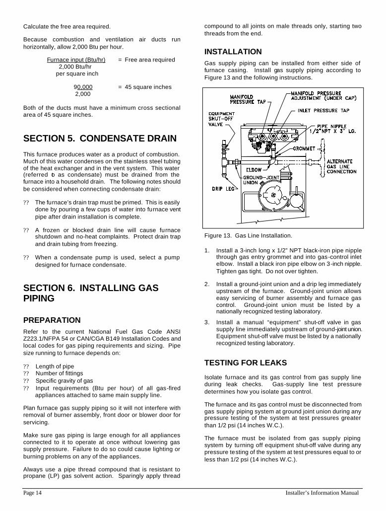
INSTALLATION Gas supply piping can be installed from either side of furnace casing. Install gas supply piping according to Figure 13 and the following instructions.
Figure 13. Gas Line Installation.
1. Install a 3-inch long x 1/2” NPT black-iron pipe nipple through gas entry grommet and into gas-control inlet elbow. Install a black iron pipe elbow on 3-inch nipple. Tighten gas tight. Do not over tighten.
2. Install a ground-joint union and a drip leg immediately upstream of the furnace. Ground-joint union allows easy servicing of burner assembly and furnace gas control. Ground-joint union must be listed by a nationally recognized testing laboratory.
3. Install a manual “equipment” shut-off valve in gas supply line immediately upstream of ground-joint union. Equipment shut-off valve must be listed by a nationally recognized testing laboratory.
TESTING FOR LEAKS
Isolate furnace and its gas control from gas supply line during leak checks. Gas-supply line test pressure determines how you isolate gas control.
The furnace and its gas control must be disconnected from gas supply piping system at ground joint union during any pressure testing of the system at test pressures greater than 1/2 psi (14 inches W.C.).
The furnace must be isolated from gas supply piping system by turning off equipment shut-off valve during any pressure testing of the system at test pressures equal to or less than 1/2 psi (14 inches W.C.).
Installer’s Information Manual Page 15
WARNING: When test pressure is above 1/2 psi (14 inches W.C.), completely disconnect furnace and gas control from gas supply line. Failure to isolate furnace and gas control from test pressure could damage them, causing gas to leak, resulting in fire or explosion.
Use a commercial soap solution made to detect leaks and check all gas piping connections. Bubbles indicate gas leakage. Seal all leaks before proceeding.
SECTION 7. INSTALLING ELECTRICAL WIRING
CAUTION: Label all wires prior to disconnection when servicing controls. Wiring errors can cause improper and dangerous operation. When replacing original wire, use same type, color, or equivalent wire. Remember to renumber wire ends. Verify proper operation after servicing.
115 VOLT WIRING
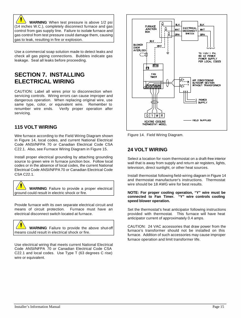
Wire furnace according to the Field Wiring Diagram shown in Figure 14, local codes, and current National Electrical Code ANSI/NFPA 70 or Canadian Electrical Code CSA C22.1. Also, see Furnace Wiring Diagram in Figure 15.
Install proper electrical grounding by attaching grounding source to green wire in furnace junction box. Follow local codes or in the absence of local codes, the current National Electrical Code ANSI/NFPA 70 or Canadian Electrical Code CSA C22.1.
WARNING: Failure to provide a proper electrical ground could result in electric shock or fire.
Provide furnace with its own separate electrical circuit and means of circuit protection. Furnace must have an electrical disconnect switch located at furnace.
WARNING: Failure to provide the above shut-off means could result in electrical shock or fire.
Use electrical wiring that meets current National Electrical Code ANSI/NFPA 70 or Canadian Electrical Code CSA C22.1 and local codes. Use Type T (63 degrees C rise) wire or equivalent.
Figure 14. Field Wiring Diagram.
24 VOLT WIRING
Select a location for room thermostat on a draft-free interior wall that is away from supply and return air registers, lights, television, direct sunlight, or other heat sources.
Install thermostat following field-wiring diagram in Figure 14 and thermostat manufacturer's instructions. Thermostat wire should be 18 AWG wire for best results.
NOTE: For proper cooling operation, “Y” wire must be connected to Fan Timer. “Y” wire controls cooling speed blower operation.
Set the thermostat's heat anticipator following instructions provided with thermostat. This furnace will have heat anticipator current of approximately 0.4 amps.
CAUTION: 24 VAC accessories that draw power from the furnace's transformer should not be installed on this furnace. Addition of such accessories may cause improper furnace operation and limit transformer life.
Page 16 Installer’s Information Manual
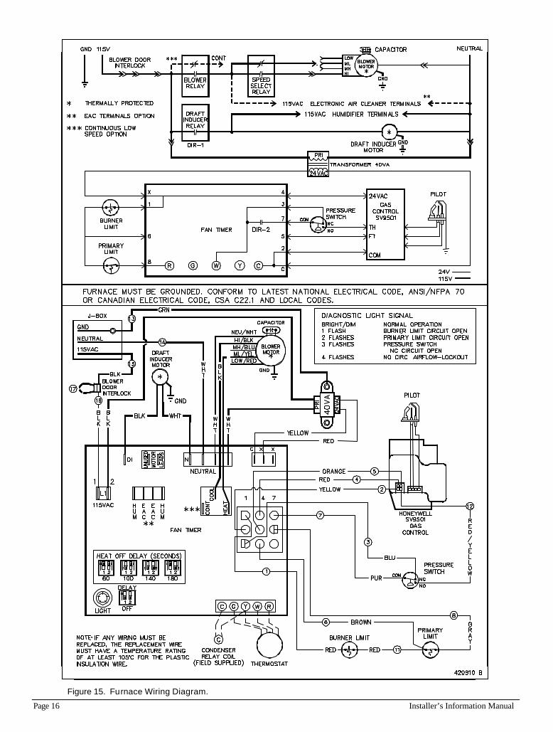
Figure 15. Furnace Wiring Diagram.
Installer’s Information Manual Page 17
SECTION 8. SEQUENCE OF OPERATION
HEATING MODE 1. Thermostat calls for heat ("R" and "W" terminals
connected). Fan Timer verifies that burner limits, primary limit and pressure switches are in normally closed (NC) position.
2. Draft-inducer relay is energized and draft inducer motor starts. Pressure switch normally open contacts close after a short delay, energizing gas control.
3. Gas control provides power to igniter and pilot valve to light pilot. After proving pilot flame, the main valve opens and igniter turns off.
NOTE: If the gas control does not sense a pilot flame within 30 seconds, it will turn off the igniter while continuing to purge the gas line. After 30 seconds, the igniter will turn on again. If a pilot is not sensed in the next 30 seconds, the gas control will turn off for 5 minutes. This sequence will continue as long as there is a call for heat.
4. Fan Timer energizes main blower in 30 seconds.
5. After thermostat is satisfied, gas control is de-energized. After a 5 second post-purge, draft inducer de-energizes and returns pressure switch to normally closed (NC) position.
6. Main blower remains energized for 60 to 180 seconds depending on heating blower off-delay setting.
NOTE: This furnace will lockout if the main blower fails in heating mode. During lockout, the Fan Timer's diagnostic light signal will be 4 flashes. The furnace's Fan Timer can be reset by cycling 115-volt power to furnace.
NOTE: On each heating cycle, this furnace verifies that the pressure switch did not stick closed on the previous cycle. This condition is detected by checking the pressure switch's normally closed circuit. If the normally closed circuit is open, furnace will not operate and the Fan Timer's diagnostic light signal will be 3 flashes.
COOLING MODE Thermostat calls for cooling ("R", "Y" and "G" terminals connected). Condensing unit contactor closes, energizing condensing unit. Fan Timer energizes main blower on cooling speed after a short delay. After thermostat is satisfied, condensing unit contactor is de-energized. Main blower remains energized for 60 seconds.
CONSTANT FAN MODE Thermostat calls for constant fan ("R" and "G" terminals connected). Fan Timer energizes main blower on heating speed.
A call for cooling mode while in constant fan mode causes main blower to change from heating to cooling speed. Sixty seconds after the call for cooling mode ends, main blower changes back to heating speed. A call for heating mode while in constant fan mode does not effect main blower operation. The main blower runs constantly on heating speed.
CONTINUOUS LOW-SPEED FAN OPTION Some models are equipped with a fan timer that allows continuous low-speed fan as an option. When available, this option can be used to operate the blower on low speed anytime the blower is not otherwise running on heating or cooling speed. These models do not have electronic air cleaner terminals on the fan timer.
To use this option, follow these steps:
1. Disconnect electrical power
2. Remove insulator cap from “CONT” terminal on Fan Timer.
3. Plug blower low-speed wire (red wire) into “CONT” terminal.
4. Place insulator cap on “UNUSED MOTOR LEAD” terminal on Fan Timer.
5. Reconnect power. Motor will start on low speed immediately.
ELECTRONIC AIR CLEANER OPTION For models with Electronic Air-Cleaner (EAC) terminals, the Fan Timer "EAC" terminals are energized with 115 VAC when main blower is energized. "EAC" terminals are 1/4 inch quick connect tabs located under breakaway covers. Use insulated quick connects when connecting to "EAC" terminals. Limit total "EAC" current plus main blower current to 15 amps max.
HUMIDIFIER Fan Timer "HUM" terminals are energized with 115 VAC (1 amp. Max.) when draft inducer is energized. "HUM" terminals are 1/4 inch quick connect tabs located under breakaway covers. Use insulated quick connects when connecting to "HUM" terminals.
BURNER LIMIT CIRCUIT OPEN If the burner limit circuit opens: burners turn off, draft inducer stays on, main blower stays on, there is no 24 volt power on the "R" terminal and diagnostic light signal is 1 flash.
PRIMARY LIMIT CIRCUIT OPEN If the primary limit circuit opens: burners turn off, draft inducer turns off, main blower stays on, there is no 24 volt power on the "R" terminal and the diagnostic light signal is 2 flashes.
Page 18 Installer’s Information Manual
SECTION 9. INSTALLING DUCT SYSTEM
Properly size duct system based on heat loss and heat gain calculations to ensure good heating and cooling installations, potentially fewer call-backs, and delivery of required circulating air. Install duct system to meet current Standard for Installations of Warm Air Heating and Air Systems ASHRAE/NFPA 90 and local codes.
CAUTION: Failure to follow these standards could reduce airflow or increase air leakage, resulting in reduced system performance or furnace damage.
Design duct system so furnace will operate at a static pressure of 0.50 inches W.C. or less. This static pressure limitation includes the total pressure losses on both supply air side and return air side of system. Supply side pressure loss includes cooling coil, ducts and room registers. Return side pressure loss includes return grilles and ducts. Pressure losses are calculated based on 400 CFM per ton of cooling.
SUPPLY AIR DUCT WORK
Supply air duct (plenum) connections must be at least as big as furnace supply opening. Seal supply-air ductwork to furnace casing, walls, ceilings or floors it passes through. End ductwork outside furnace space.
On furnaces not equipped with a cooling coil, a removable access panel that is large enough to allow viewing of the heat exchanger should be provided in the supply duct. The access panel should be accessible when the furnace is installed. Seal access-panel cover to prevent leaks.
RETURN AIR DUCT WORK
When furnace is installed so that supply air ducts carry air to areas outside the space containing the furnace, return air must be handled by a duct(s) sealed to furnace casing and terminating outside the space containing furnace.
WARNING: Failure to seal return-air ductwork could allow combustion products to enter circulating air stream resulting in injury or death by asphyxiation.
Air delivery above 1800 CFM requires that both sides of furnace be used for return air, or a combination of one side and bottom or bottom only.
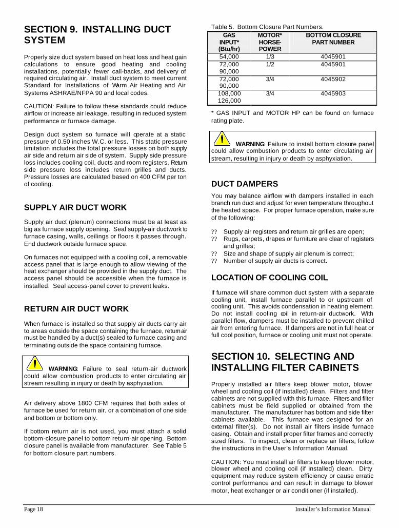
If bottom return air is not used, you must attach a solid bottom-closure panel to bottom return-air opening. Bottom closure panel is available from manufacturer. See Table 5 for bottom closure part numbers.
Table 5. Bottom Closure Part Numbers. GAS
INPUT* (Btu/hr)
MOTOR* HORSE- POWER
BOTTOM CLOSURE PART NUMBER
54,000 1/3 4045901 72,000 90,000
1/2
4045901
72,000 90,000
3/4 4045902
108,000 126,000
3/4 4045903
* GAS INPUT and MOTOR HP can be found on furnace rating plate.
WARNING: Failure to install bottom closure panel could allow combustion products to enter circulating air stream, resulting in injury or death by asphyxiation.
DUCT DAMPERS You may balance airflow with dampers installed in each branch run duct and adjust for even temperature throughout the heated space. For proper furnace operation, make sure of the following:
?? Supply air registers and return air grilles are open; ?? Rugs, carpets, drapes or furniture are clear of registers
and grilles; ?? Size and shape of supply air plenum is correct; ?? Number of supply air ducts is correct.
LOCATION OF COOLING COIL
If furnace will share common duct system with a separate cooling unit, install furnace parallel to or upstream of cooling unit. This avoids condensation in heating element. Do not install cooling coil in return-air ductwork. With parallel flow, dampers must be installed to prevent chilled air from entering furnace. If dampers are not in full heat or full cool position, furnace or cooling unit must not operate.
SECTION 10. SELECTING AND INSTALLING FILTER CABINETS
Properly installed air filters keep blower motor, blower wheel and cooling coil (if installed) clean. Filters and filter cabinets are not supplied with this furnace. Filters and filter cabinets must be field supplied or obtained from the manufacturer. The manufacturer has bottom and side filter cabinets available. This furnace was designed for an external filter(s). Do not install air filters inside furnace casing. Obtain and install proper filter frames and correctly sized filters. To inspect, clean or replace air filters, follow the instructions in the User’s Information Manual.
CAUTION: You must install air filters to keep blower motor, blower wheel and cooling coil (if installed) clean. Dirty equipment may reduce system efficiency or cause erratic control performance and can result in damage to blower motor, heat exchanger or air conditioner (if installed).
Installer’s Information Manual Page 19
Follow these instructions and the filter manufacturer's instructions for minimum size and quantity recommendations. Air velocity must not exceed 300 feet per minute through low velocity disposable filters. Air velocity must not exceed 650 feet per minute through high velocity washable filters. Undersized filters reduce airflow and can adversely affect furnace and cooling system operation.
See Table 6 for recommended filter size for bottom return installations. Side return filters must be at least 16" X 25" X 1", high-velocity washable filters.
Table 6. Recommended Filter Size--Bottom Return. GAS
INPUT* (Btu/hr)
MOTOR* HORSE-POWER
DISPOSABLE AIR FILTER
- two required (inches)
HIGH- VELOCITY
WASHABLE AIR FILTER
54,000 1/3 16 X 25 X 1 16 X 25 X 1 72,000 90,000
1/2
16 X 25 X 1 16 X 25 X 1
72,000 90,000 108,000 126,000
3/4 20 X 25 X 1 20 X 25 X 1
* GAS INPUT and MOTOR HP can be found on furnace rating plate.
FILTER CABINETS Use a bottom filter cabinet, side filter cabinet, or return-air filter grille. Field fabricated filter cabinets should allow 1 inch spacing between filter and furnace. Placing a field supplied filter directly against furnace bottom or side will decrease airflow and adversely affect furnace operation. Filter cabinets that provide correct filter spacing to ensure designed airflow are available from the manufacturer.
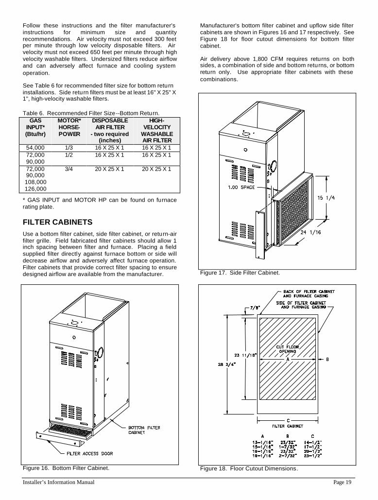
Figure 16. Bottom Filter Cabinet.
Manufacturer's bottom filter cabinet and upflow side filter cabinets are shown in Figures 16 and 17 respectively. See Figure 18 for floor cutout dimensions for bottom filter cabinet.
Air delivery above 1,800 CFM requires returns on both sides, a combination of side and bottom returns, or bottom return only. Use appropriate filter cabinets with these combinations.
Figure 17. Side Filter Cabinet.
Figure 18. Floor Cutout Dimensions.
Page 20 Installer’s Information Manual
SECTION 11. CHECKS BEFORE STARTING FURNACE
Before starting furnace for the first time, be sure you can answer "Yes" to each of these questions:
1. Is furnace properly equipped to operate with available fuel?
2. Is furnace level?
3. Have you cleared away all loose construction and insulation materials?
4. Is furnace installed with proper clearances?
5. Does furnace have sufficient combustion and ventilation air?
6. Is the vent system sloped toward the furnace at least 1/4 inch per foot?
7. Have you checked the vent system for leaks?
8. Did you completely check gas pipe and controls for gas leaks?
9. Does electrical wiring follow current National Electrical Code ANSI/NFPA 70 or Canadian Electrical Code CSA C22.1 as well as local codes?
10. Is furnace electrically grounded?
11. Is room thermostat properly installed and heat anticipator set correctly?
12. Is duct system correctly sized and sealed?
13. Are proper air filter cabinets installed?
14. Are air filters in place and correctly sized?
SECTION 12. GAS SUPPLY PRESSURE AND PILOT ADJUSTMENT
You will need a 0 to 15 inch water manometer with 0.1 inch resolution and a 1/8" NPT manual shut-off valve to measure actual gas pressure.
CHECKING GAS SUPPLY PRESSURE 1. Turn off gas at equipment shut-off valve in gas supply
line just ahead of furnace.
2. Remove three screws holding burner access panel in place. Remove burner access panel.
3. Remove inlet pressure plug from gas control. See Figure 13.
4. Install 1/8" NPT manual shut-off valve in hole vacated by plug. Make sure valve is in off position.
5. Attach manometer to 1/8" NPT manual shut-off valve just installed.
6. Slowly open equipment shut-off valve in gas supply line just ahead of furnace.
7. Slowly open 1/8" NPT manual shut-off valve leading to manometer.
8. Turn on all gas appliances attached to gas supply line.
9. With furnace operating, read gas supply pressure on manometer.
?? Natural gas supply pressure must be between 5 and 7 inches W.C.
?? Propane gas (LP) supply pressure must be between 11 and 13 inches W.C.
10. If gas supply pressure is not within these limits, call gas supplier. Turn off all gas appliances attached to gas supply line.
11. Shut off furnace.
12. Turn off gas at equipment shut-off valve in gas supply line just ahead of furnace. Remove shut-off valve from gas-control inlet pressure tap. Install pressure tap plug. Turn on gas.
13. Replace burner access panel using three screws removed in step 2.
PILOT FLAME ADJUSTMENT
Before adjusting pilot flame, confirm that gas supply pressure is correct, as explained above.
NOTE: Pilot flame adjustment was checked at the factory and should not require adjustment. However; pilot adjustment is possible if necessary.
1. Remove three screws holding burner access panel in place. Remove burner access panel.
2. Start furnace following "Operating Instructions" on front door.
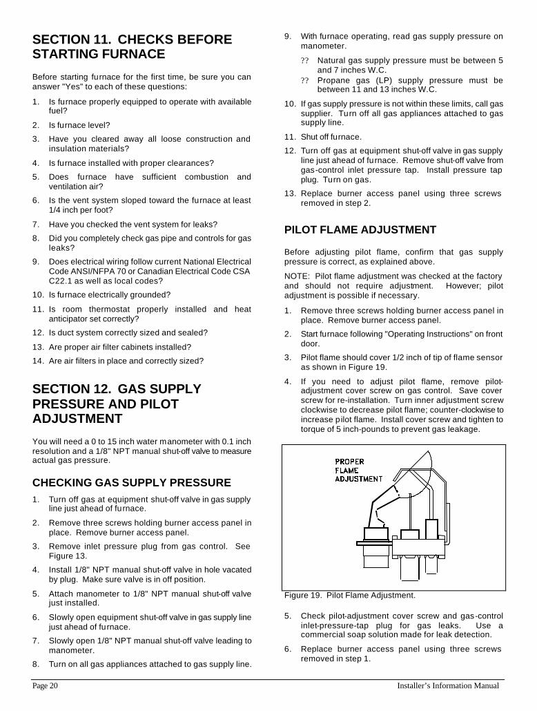
3. Pilot flame should cover 1/2 inch of tip of flame sensor as shown in Figure 19.
4. If you need to adjust pilot flame, remove pilot-adjustment cover screw on gas control. Save cover screw for re-installation. Turn inner adjustment screw clockwise to decrease pilot flame; counter-clockwise to increase pilot flame. Install cover screw and tighten to torque of 5 inch-pounds to prevent gas leakage.
Figure 19. Pilot Flame Adjustment.
5. Check pilot-adjustment cover screw and gas-control inlet-pressure-tap plug for gas leaks. Use a commercial soap solution made for leak detection.
6. Replace burner access panel using three screws removed in step 1.
Installer’s Information Manual Page 21
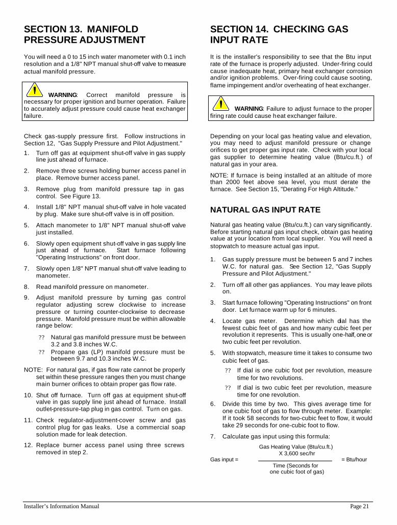
SECTION 13. MANIFOLD PRESSURE ADJUSTMENT
You will need a 0 to 15 inch water manometer with 0.1 inch resolution and a 1/8" NPT manual shut-off valve to measure actual manifold pressure.
WARNING: Correct manifold pressure is necessary for proper ignition and burner operation. Failure to accurately adjust pressure could cause heat exchanger failure.
Check gas-supply pressure first. Follow instructions in Section 12, "Gas Supply Pressure and Pilot Adjustment."
1. Turn off gas at equipment shut-off valve in gas supply line just ahead of furnace.
2. Remove three screws holding burner access panel in place. Remove burner access panel.
3. Remove plug from manifold pressure tap in gas control. See Figure 13.
4. Install 1/8" NPT manual shut-off valve in hole vacated by plug. Make sure shut-off valve is in off position.
5. Attach manometer to 1/8" NPT manual shut-off valve just installed.
6. Slowly open equipment shut-off valve in gas supply line just ahead of furnace. Start furnace following "Operating Instructions" on front door.
7. Slowly open 1/8" NPT manual shut-off valve leading to manometer.
8. Read manifold pressure on manometer.
9. Adjust manifold pressure by turning gas control regulator adjusting screw clockwise to increase pressure or turning counter-clockwise to decrease pressure. Manifold pressure must be within allowable range below:
?? Natural gas manifold pressure must be between 3.2 and 3.8 inches W.C.
?? Propane gas (LP) manifold pressure must be between 9.7 and 10.3 inches W.C.
NOTE: For natural gas, if gas flow rate cannot be properly set within these pressure ranges then you must change main burner orifices to obtain proper gas flow rate.
10. Shut off furnace. Turn off gas at equipment shut-off valve in gas supply line just ahead of furnace. Install outlet-pressure-tap plug in gas control. Turn on gas.
11. Check regulator-adjustment-cover screw and gas control plug for gas leaks. Use a commercial soap solution made for leak detection.
12. Replace burner access panel using three screws removed in step 2.
SECTION 14. CHECKING GAS INPUT RATE
It is the installer's responsibility to see that the Btu input rate of the furnace is properly adjusted. Under-firing could cause inadequate heat, primary heat exchanger corrosion and/or ignition problems. Over-firing could cause sooting, flame impingement and/or overheating of heat exchanger.
WARNING: Failure to adjust furnace to the proper firing rate could cause heat exchanger failure.
Depending on your local gas heating value and elevation, you may need to adjust manifold pressure or change orifices to get proper gas input rate. Check with your local gas supplier to determine heating value (Btu/cu.ft.) of natural gas in your area.
NOTE: If furnace is being installed at an altitude of more than 2000 feet above sea level, you must derate the furnace. See Section 15, "Derating For High Altitude."
NATURAL GAS INPUT RATE
Natural gas heating value (Btu/cu.ft.) can vary significantly. Before starting natural gas input check, obtain gas heating value at your location from local supplier. You will need a stopwatch to measure actual gas input.
1. Gas supply pressure must be between 5 and 7 inches W.C. for natural gas. See Section 12, "Gas Supply Pressure and Pilot Adjustment."
2. Turn off all other gas appliances. You may leave pilots on.
3. Start furnace following "Operating Instructions" on front door. Let furnace warm up for 6 minutes.
4. Locate gas meter. Determine which dial has the fewest cubic feet of gas and how many cubic feet per revolution it represents. This is usually one-half, one or two cubic feet per revolution.
5. With stopwatch, measure time it takes to consume two cubic feet of gas.
?? If dial is one cubic foot per revolution, measure time for two revolutions.
?? If dial is two cubic feet per revolution, measure time for one revolution.
6. Divide this time by two. This gives average time for one cubic foot of gas to flow through meter. Example: If it took 58 seconds for two-cubic feet to flow, it would take 29 seconds for one-cubic foot to flow.
7. Calculate gas input using this formula:
Gas Heating Value (Btu/cu.ft.) X 3,600 sec/hr Gas input = = Btu/hour Time (Seconds for one cubic foot of gas)
Page 22 Installer’s Information Manual
Example:
Assume it took 29 seconds for one cubic foot of gas to flow and heating value of 1,000 Btu/cu.ft.
1,000 x 3,600 Gas Input = = 124,138 Btu per hour 29
If you left no other pilots on, this is the furnace gas input.
8. If you left water heater, dryer or range pilots on, allow for them in calculating correct furnace gas input. A quick way is to allow 1,000 Btu per hour for a water heater, 500 Btu per hour for dryer and 500 Btu per hour for each range burner pilot.
Example: If you left gas water heater, dryer, two range burner pilots
and one oven pilot on, allow: Water heater pilot 1,000 Btu per hour Dryer pilot 500 Btu per hour 2 range burner pilots 1,000 Btu per hour 1 range oven pilot 500 Btu per hour 3,000 Btu per hour
Subtracting 3,000 Btu per hour from 124,138 Btu per hour measured above equals 121,138 Btu per hour. This would be the correct furnace gas input after allowing for pilots left on.
9. Manifold pressure may be adjusted within the range of 3.2 inches W.C. to 3.8 inches W.C. to get rated input ± 2 percent. See Section 13, "Manifold Pressure Adjustment." If you cannot get rated input with manifold pressure within the allowable range, you must change orifices. See Section 17, "Changing Main Burner Orifices."
PROPANE (LP) GAS INPUT RATE
WARNING: Propane (LP) gas installations do not have gas meters to double-check input rate. Measure manifold pressure with an accurate manometer. Failure to accurately adjust pressure could cause heat exchanger failure.
1. Make sure you have correct pilot orifice and main burner orifices.
2. Gas supply pressure must be between 11 and 13 inches W.C. for propane (LP) gas. See Section 12, "Gas Supply Pressure and Pilot Adjustment."
3. Start furnace following "Operating Instructions" on front door.
4. Let furnace warm up for 6 minutes. 5. Adjust manifold pressure to 10.0 inches W.C. ± 0.3
inches W.C. See Section 13, "Manifold Pressure Adjustment."
WARNING: Do not set Propane (LP) manifold pressure at 11.0 inches W.C. It could cause heat exchanger failure.
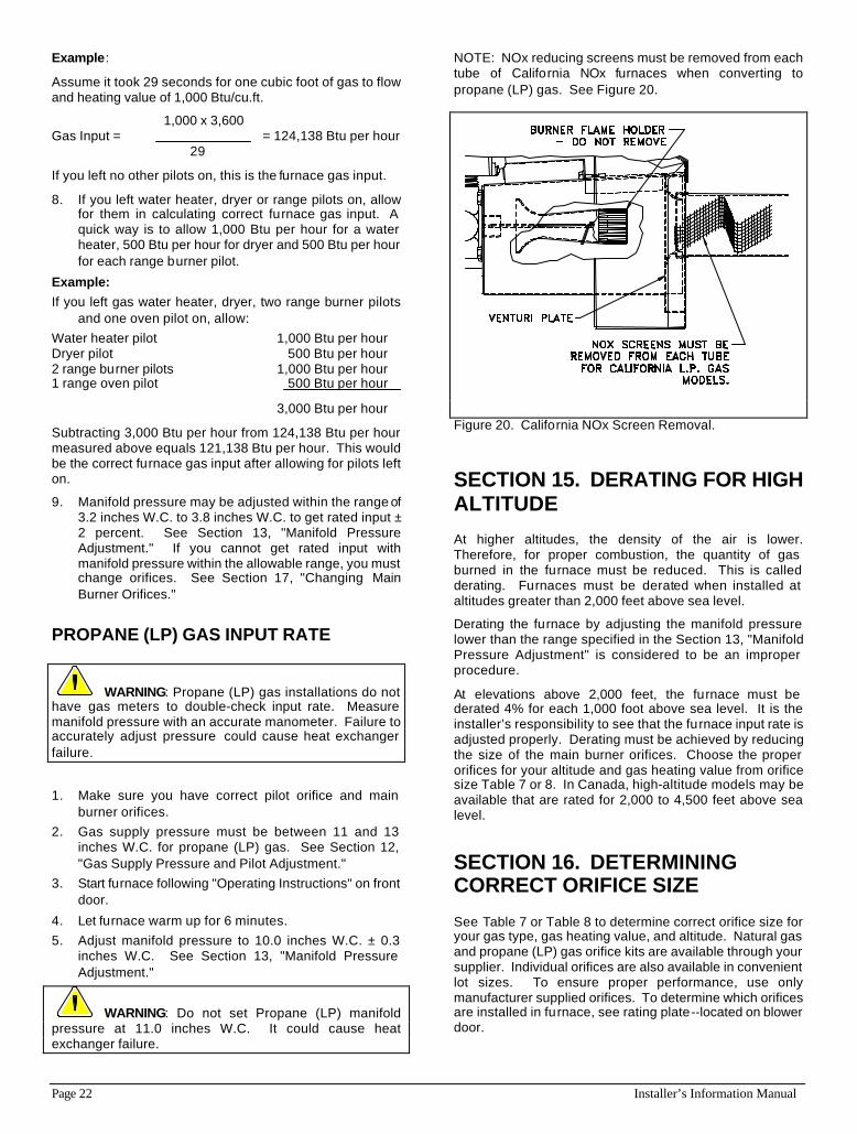
NOTE: NOx reducing screens must be removed from each tube of California NOx furnaces when converting to propane (LP) gas. See Figure 20.
Figure 20. California NOx Screen Removal.
SECTION 15. DERATING FOR HIGH ALTITUDE
At higher altitudes, the density of the air is lower. Therefore, for proper combustion, the quantity of gas burned in the furnace must be reduced. This is called derating. Furnaces must be derated when installed at altitudes greater than 2,000 feet above sea level.
Derating the furnace by adjusting the manifold pressure lower than the range specified in the Section 13, "Manifold Pressure Adjustment" is considered to be an improper procedure.
At elevations above 2,000 feet, the furnace must be derated 4% for each 1,000 foot above sea level. It is the installer’s responsibility to see that the furnace input rate is adjusted properly. Derating must be achieved by reducing the size of the main burner orifices. Choose the proper orifices for your altitude and gas heating value from orifice size Table 7 or 8. In Canada, high-altitude models may be available that are rated for 2,000 to 4,500 feet above sea level.
SECTION 16. DETERMINING CORRECT ORIFICE SIZE
See Table 7 or Table 8 to determine correct orifice size for your gas type, gas heating value, and altitude. Natural gas and propane (LP) gas orifice kits are available through your supplier. Individual orifices are also available in convenient lot sizes. To ensure proper performance, use only manufacturer supplied orifices. To determine which orifices are installed in furnace, see rating plate--located on blower door.
Installer’s Information Manual Page 23
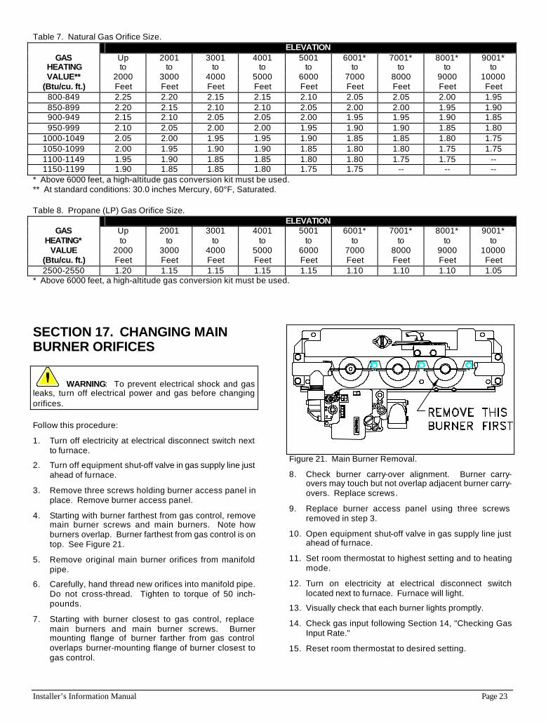
Table 7. Natural Gas Orifice Size. ELEVATION
GAS Up 2001 3001 4001 5001 6001* 7001* 8001* 9001* HEATING to to to to to to to to to VALUE** 2000 3000 4000 5000 6000 7000 8000 9000 10000
(Btu/cu. ft.) Feet Feet Feet Feet Feet Feet Feet Feet Feet 800-849 2.25 2.20 2.15 2.15 2.10 2.05 2.05 2.00 1.95 850-899 2.20 2.15 2.10 2.10 2.05 2.00 2.00 1.95 1.90 900-949 2.15 2.10 2.05 2.05 2.00 1.95 1.95 1.90 1.85 950-999 2.10 2.05 2.00 2.00 1.95 1.90 1.90 1.85 1.80
1000-1049 2.05 2.00 1.95 1.95 1.90 1.85 1.85 1.80 1.75 1050-1099 2.00 1.95 1.90 1.90 1.85 1.80 1.80 1.75 1.75 1100-1149 1.95 1.90 1.85 1.85 1.80 1.80 1.75 1.75 -- 1150-1199 1.90 1.85 1.85 1.80 1.75 1.75 -- -- --
* Above 6000 feet, a high-altitude gas conversion kit must be used. ** At standard conditions: 30.0 inches Mercury, 60°F, Saturated.
Table 8. Propane (LP) Gas Orifice Size. ELEVATION
GAS Up 2001 3001 4001 5001 6001* 7001* 8001* 9001* HEATING* to to to to to to to to to
VALUE 2000 3000 4000 5000 6000 7000 8000 9000 10000 (Btu/cu. ft.) Feet Feet Feet Feet Feet Feet Feet Feet Feet 2500-2550 1.20 1.15 1.15 1.15 1.15 1.10 1.10 1.10 1.05
* Above 6000 feet, a high-altitude gas conversion kit must be used.
SECTION 17. CHANGING MAIN BURNER ORIFICES
WARNING: To prevent electrical shock and gas leaks, turn off electrical power and gas before changing orifices.
Follow this procedure:
1. Turn off electricity at electrical disconnect switch next to furnace.
2. Turn off equipment shut-off valve in gas supply line just ahead of furnace.
3. Remove three screws holding burner access panel in place. Remove burner access panel.
4. Starting with burner farthest from gas control, remove main burner screws and main burners. Note how burners overlap. Burner farthest from gas control is on top. See Figure 21.
5. Remove original main burner orifices from manifold pipe.
6. Carefully, hand thread new orifices into manifold pipe. Do not cross-thread. Tighten to torque of 50 inch-pounds.
7. Starting with burner closest to gas control, replace main burners and main burner screws. Burner mounting flange of burner farther from gas control overlaps burner-mounting flange of burner closest to gas control.
Figure 21. Main Burner Removal.
8. Check burner carry-over alignment. Burner carry-overs may touch but not overlap adjacent burner carry-overs. Replace screws.
9. Replace burner access panel using three screws removed in step 3.
10. Open equipment shut-off valve in gas supply line just ahead of furnace.
11. Set room thermostat to highest setting and to heating mode.
12. Turn on electricity at electrical disconnect switch located next to furnace. Furnace will light.
13. Visually check that each burner lights promptly.
14. Check gas input following Section 14, "Checking Gas Input Rate."
15. Reset room thermostat to desired setting.
Page 24 Installer’s Information Manual
SECTION 18. ADJUSTING BLOWER SPEED
Determine initial heating and cooling speeds in system design stage. See Specification Sheet for airflow data. Depending on tests performed in following sections, you may need to change blower motor speed.
CAUTION: Heating speed tap should not be reduced below factory setting. Doing so may result in inadequate air circulation, and could cause excessive air temperature rise through furnace. This could cause a high-temperature limit switch to cycle burners on and off, reducing furnace efficiency and shortening heat exchanger life.
All models have these four motor speed designations:
High Speed (HI) Black wire Medium High Speed (MH) Blue wire Medium Low Speed (ML) Yellow wire Low Speed (LO) Red wire
WARNING: To prevent electric shock, turn off electrical power to furnace before changing blower motor speed.
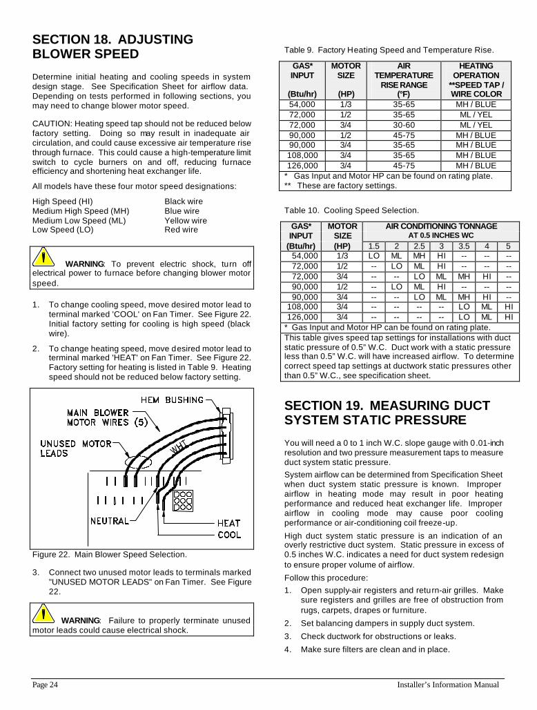
1. To change cooling speed, move desired motor lead to terminal marked 'COOL' on Fan Timer. See Figure 22. Initial factory setting for cooling is high speed (black wire).
2. To change heating speed, move desired motor lead to terminal marked 'HEAT' on Fan Timer. See Figure 22. Factory setting for heating is listed in Table 9. Heating speed should not be reduced below factory setting.
Figure 22. Main Blower Speed Selection.
3. Connect two unused motor leads to terminals marked "UNUSED MOTOR LEADS" on Fan Timer. See Figure 22.
WARNING: Failure to properly terminate unused motor leads could cause electrical shock.
Table 9. Factory Heating Speed and Temperature Rise.
GAS* INPUT
(Btu/hr)
MOTOR SIZE
(HP)
AIR TEMPERATURE
RISE RANGE (°F)
HEATING OPERATION
**SPEED TAP / WIRE COLOR
54,000 1/3 35-65 MH / BLUE 72,000 1/2 35-65 ML / YEL 72,000 3/4 30-60 ML / YEL 90,000 1/2 45-75 MH / BLUE 90,000 3/4 35-65 MH / BLUE 108,000 3/4 35-65 MH / BLUE 126,000 3/4 45-75 MH / BLUE
* Gas Input and Motor HP can be found on rating plate. ** These are factory settings.
Table 10. Cooling Speed Selection.
GAS* MOTOR AIR CONDITIONING TONNAGE INPUT SIZE AT 0.5 INCHES WC
(Btu/hr) (HP) 1.5 2 2.5 3 3.5 4 5 54,000 1/3 LO ML MH HI -- -- -- 72,000 1/2 -- LO ML HI -- -- -- 72,000 3/4 -- -- LO ML MH HI -- 90,000 1/2 -- LO ML HI -- -- -- 90,000 3/4 -- -- LO ML MH HI --
108,000 3/4 -- -- -- -- LO ML HI 126,000 3/4 -- -- -- -- LO ML HI
* Gas Input and Motor HP can be found on rating plate. This table gives speed tap settings for installations with duct static pressure of 0.5” W.C. Duct work with a static pressure less than 0.5” W.C. will have increased airflow. To determine correct speed tap settings at ductwork static pressures other than 0.5” W.C., see specification sheet.
SECTION 19. MEASURING DUCT SYSTEM STATIC PRESSURE
You will need a 0 to 1 inch W.C. slope gauge with 0.01-inch resolution and two pressure measurement taps to measure duct system static pressure. System airflow can be determined from Specification Sheet when duct system static pressure is known. Improper airflow in heating mode may result in poor heating performance and reduced heat exchanger life. Improper airflow in cooling mode may cause poor cooling performance or air-conditioning coil freeze-up.
High duct system static pressure is an indication of an overly restrictive duct system. Static pressure in excess of 0.5 inches W.C. indicates a need for duct system redesign to ensure proper volume of airflow.
Follow this procedure: 1. Open supply-air registers and return-air grilles. Make
sure registers and grilles are free of obstruction from rugs, carpets, drapes or furniture.
2. Set balancing dampers in supply duct system.
3. Check ductwork for obstructions or leaks.
4. Make sure filters are clean and in place.

Installer’s Information Manual Page 25
5. Make sure that blower speed taps are set for proper heating and cooling. Refer to Section 18, "Adjusting Blower Speed." Heating speed should be set according to Table 9. Cooling speed should be set to meet cooling equipment requirements. See Table 10 for cooling airflow capacities at 0.5 inch W.C.
6. Place slope gauge near furnace, level and adjust scale to read 0.00 inches W.C.
7. Insert one static pressure tap into supply-air duct between furnace and cooling coil or in supply air plenum for heating only systems. Connect this pressure tap to positive pressure side of slope gauge.
8. Insert other static pressure tap in return air plenum. Connect this pressure tap to negative pressure side of slope gauge.
9. Start blower.
?? Blower heating speed can be run by jumping terminals "R" and "G" on 24-volt terminal block located on Fan Timer.
?? Blower cooling speed can be run by jumping terminals "R" and "Y" on 24-volt terminal block located on Fan Timer.
NOTE: On cooling speed, there is a short on-delay before blower starts and a 60-second off-delay before blower stops.
10. Read duct system static pressure from slope gauge. NOTE: If air filter location is upstream of return-air pressure
tap, static pressure must be adjusted to exclude filter pressure drop. Do this by subtracting 0.08 inches W.C. from the measured static pressure.
Duct System = Measured - 0.08 inches W.C. Static Pressure Pressure
11. Remove jumper wire from 24-volt terminal strip. Remove pressure taps and seal holes in ductwork.
SECTION 20. MEASURING AIR TEMPERATURE RISE
You will need 2 thermometers with 1-degree resolution capable of reading up to 175 degrees F.
Air temperature rise (supply air temperature minus return air temperature) must be within allowable air-temperature rise range specified on furnace rating plate and in Table 9.
Follow this procedure: 1. Open supply air registers and return air grilles. Make
sure registers and grilles are free of obstruction from rugs, carpets, drapes or furniture.
2. Set balancing dampers in supply duct system.
3. Check ductwork for obstructions or leaks.
4. Make sure filters are clean and in place.
5. Make sure that blower speed taps are set for proper heating and cooling. Refer to Section 18, "Adjusting Blower Speed." Heating speed should be set according to Table 9. Cooling speed should be set to
meet cooling equipment requirements. See Table 10 for cooling airflow capacities at 0.5 inch W.C.
6. Place one thermometer in supply air plenum approximately 2 feet from furnace. Locate thermometer tip in center of plenum to ensure proper temperature measurement.
7. Place second thermometer in return-air duct approximately 2 feet from furnace. Locate thermometer tip in center of duct to ensure proper temperature measurement.
8. Set room thermostat on highest temperature setting. Operate furnace 6 minutes. Record supply air and return air temperatures.
9. Calculate air temperature rise by subtracting return air temperature from supply air temperature.
?? If air temperature rise is above temperature rise range specified in Table 9, furnace is overfired or has insufficient airflow. Check gas input following the instructions in Section 14, "Checking Gas Input Rate." If air temperature rise is still above temperature rise range specified, more heating airflow is needed. Change blower heating speed to a higher setting following instructions in Section 18, "Adjusting Blower Speed."
?? If air temperature rise is below temperature rise range specified in Table 9, furnace is underfired or has too much airflow. Check gas input following the instructions in Section 14, "Checking Gas Input Rate." If air temperature rise is still below temperature rise range specified, less heating airflow is needed. Change blower heating speed to a lower setting following instructions in Section 18, "Adjusting Blower Speed."
?? After making adjustments, you must check air temperature rise to verify that resulting air temperature rise is within allowable range. If air temperature rise is still outside temperature rise range specified in Table 9, check duct system design with a qualified heating engineer. It may be necessary to re-size duct work. Recheck air temperature rise after revising duct systems.
10. Set room thermostat to desired setting.
11. Remove thermometers and seal ductwork holes.
SECTION 21. CHECKING CONTROLS
Before leaving work site, check to see that all controls are functioning properly. You will need a 0 to 15 inch water manometer with 0.1 inch resolution and a 1/8" NPT manual shut-off valve.
Follow this procedure: 1. Turn off electricity at electrical disconnect switch next
to furnace. 2. Remove three screws holding burner access panel in
place. Remove burner access panel.
3. Turn gas control switch to OFF position.
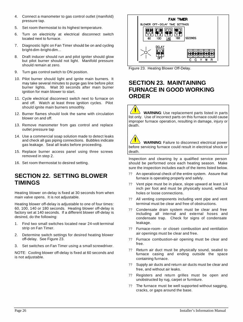
Page 26 Installer’s Information Manual
4. Connect a manometer to gas control outlet (manifold) pressure tap.
5. Set room thermostat to its highest temperature.
6. Turn on electricity at electrical disconnect switch located next to furnace.
7. Diagnostic light on Fan Timer should be on and cycling bright-dim-bright-dim...
8. Draft inducer should run and pilot igniter should glow but pilot burner should not light. Manifold pressure should remain at zero.
9. Turn gas control switch to ON position.
10. Pilot burner should light and ignite main burners. It may take several minutes to purge gas line before pilot burner lights. Wait 30 seconds after main burner ignition for main blower to start.
11. Cycle electrical disconnect switch next to furnace on and off. Watch at least three ignition cycles. Pilot should ignite main burners smoothly.
12. Burner flames should look the same with circulation blower on and off.
13. Remove manometer from gas control and replace outlet pressure tap
14. Use a commercial soap solution made to detect leaks and check all gas piping connections. Bubbles indicate gas leakage. Seal all leaks before proceeding.
15. Replace burner access panel using three screws removed in step 2.
16. Set room thermostat to desired setting.
SECTION 22. SETTING BLOWER TIMINGS
Heating blower on-delay is fixed at 30 seconds from when main valve opens. It is not adjustable.
Heating blower off-delay is adjustable to one of four times: 60, 100, 140 or 180 seconds. Heating blower off-delay is factory set at 140 seconds. If a different blower off-delay is desired, do the following:
1. Find two small switches located near 24-volt terminal strip on Fan Timer.
2. Determine switch settings for desired heating blower off-delay. See Figure 23.
3. Set switches on Fan Timer using a small screwdriver.
NOTE: Cooling blower off-delay is fixed at 60 seconds and is not adjustable.
Figure 23. Heating Blower Off-Delay.
SECTION 23. MAINTAINING FURNACE IN GOOD WORKING ORDER
WARNING: Use replacement parts listed in parts list only. Use of incorrect parts on this furnace could cause improper furnace operation, resulting in damage, injury or death.
WARNING: Failure to disconnect electrical power before servicing furnace could result in electrical shock or death.
Inspection and cleaning by a qualified service person should be performed once each heating season. Make sure the inspection includes each of the items listed below.
?? An operational check of the entire system. Assure that furnace is operating properly and safely.
?? Vent pipe must be in place, slope upward at least 1/4 inch per foot and must be physically sound, without holes or loose connections.
?? All venting components including vent pipe and vent terminal must be clear and free of obstructions.
?? Condensate drain system must be clear and free including all internal and external hoses and condensate trap. Check for signs of condensate leakage.
?? Furnace-room- or closet- combustion and ventilation air openings must be clear and free.
?? Furnace combustion-air opening must be clear and free.
?? Return air duct must be physically sound, sealed to furnace casing and ending outside the space containing furnace.
?? Supply air ducts and return air ducts must be clear and free, and without air leaks.
?? Registers and return grilles must be open and unobstructed by rug, carpet or furniture.
?? The furnace must be well supported without sagging, cracks, or gaps around the base.
Installer’s Information Manual Page 27
?? There must be no obvious signs of deterioration of the furnace. Inspection must include burners, pilot, heat exchanger, inducer pan, and draft inducer.
?? Flame holders, located inside the main burners, should be free of lint or dirt. Burners can be cleaned with compressed air.
?? Inspect all electrical wiring and connections, including electrical ground.
?? Gas pipes must be checked for leaks using a commercial soap solution made to detect leaks.
?? Main burners and pilot burner must be in good adjustment as shown in the User’s Information Manual. Main burner flame must be clear blue and centered within heat exchanger openings.
?? Check furnace area for combustible materials, flammable liquid near furnace, corrosive materials, insulation material within 12 inches of furnace, and signs of high water levels.
?? Inspect, clean, or repair as needed the following items: blower housing, blower motor, blower wheel, air filters, draft inducer, and cooling coil.
NOTE: Blower motor and inducer motor do not require oiling.
Follow these steps to remove blower assembly:
1. Turn off furnace electrical power. 2. Disconnect room thermostat wires from 24-volt terminal
strip on Fan Timer. 3. Locate five blower motor wires that feed though casing
hem.
4. Label blower motor wires for proper replacement. 5. Disconnect blower motor wires from Fan Timer. See
Figure 22. 6. Remove 2 screws holding blower door in place.
Remove blower door.
7. Pull blower motor wires through casing hem. 8. Remove power-disconnect assembly located in the
middle of blower deck. 9. Remove 2 screws holding blower assembly to blower
deck.
10. Slide blower assembly out. 11. After cleaning blower assembly, re-assemble in
reverse order making sure speed selections are in original positions.
SECTION 24. ACCESSORIES
THERMOSTATS: These are quality thermostats with the Consolidated Industries name. Choose from the T87 (round w/subbase), T834 (heating and cooling) or the T8699 (Chronotherm III)--available in white only. PROPANE CONVERSION KIT (BELOW 6,000 ft): Includes propane regulator-spring kit, propane pilot orifice and main burner orifices. HIGH-ALTITUDE PROPANE CONVERSION KIT (ABOVE 6,000 ft): Includes propane regulator-spring kit, propane pilot orifice, main burner orifices, and high-altitude pressure switch.
NATURAL GAS CONVERSION KIT (BELOW 6,000 ft): Includes natural gas regulator-spring kit, natural gas pilot orifice and main burner orifices. HIGH-ALTITUDE NATURAL GAS CONVERSION KIT (ABOVE 6,000 ft): Includes natural gas regulator-spring kit, natural gas pilot orifice, main burner orifices and high-altitude pressure switch. BOTTOM FILTER CABINET: Three sizes - one size for each furnace casing size. SIDE FILTER CABINET: Attaches to either side of furnace. One size fits all. BOTTOM CLOSURE: Seals bottom of furnace when only side return is used. FILTERS: High-velocity washable filters, available in cartons of 10. Sizes include 16 x 25 x 1 and 20 x 25 x 1.
SECTION 25. OTHER INFORMATION AND PUBLICATIONS
These publications can help you install the furnace. You can usually find these at your local library or buy them directly from the publisher. Be sure to consult current edition of each standard.
National Fuel Gas Code ANSI Z223.1/NFPA 54
Canadian Installation Codes CAN/CGA B149
National Electrical Code ANSI/NFPA Code 70
Canadian Electrical Code CSA C22.1
Standard For The Installation Of Warm Air Heating And Air Conditioning Systems.
ASHRAE/NFPA 90
For more information, contact these publishers:
ANSI: American National Standards Institute Inc. 1430 Broadway New York, New York 10018 (212) 642-4900
CSA: Canadian Standards Association 178 Rexdale Boulevard Rexdale, Ontario, Canada M9W 1R3 (416) 447-4044
ASHRAE: American Society Of Heating Refrigeration And Air-Conditioning Engineers, Inc. 1791 Tullie Circle N.E. Atlanta, GA 30329 (404) 636-8400
NFPA: National Fire Protection Association 1 Batterymarch Park Quincy, MA 02269 (617) 770-3000

![[-]GDG UPFLOW GAS FURNACE Form 92-21650-34-04...Title [-]GDG UPFLOW GAS FURNACE Form 92-21650-34-04 Subject: GAS FURNACE UPFLOW Keywords: GDG, GAS, UPFLOW, FURNACE, [-]GDG, 92-21650-34-04](https://img.dokumen.tips/doc/110x75/60adbca1a05ef2753c1c4a21/-gdg-upflow-gas-furnace-form-92-21650-34-04-title-gdg-upflow-gas-furnace.jpg)