Embed Size (px)
Citation preview

HEFFERNAN HOLLAND MORGAN
A R C H I T E C T U R E
3 1 2 S O U T H A L C AN I Z S T RE E T • P E N S AC O L A , F L O R I DA 3 2 5 0 2 • 8 5 0 4 3 3 2 79 9 • A AC 0 0 1 9 4 2 • H H MA . C O M
FTEV 16-1066 FA4417-16-R-0025 CONSTRUCT TRAINING FACILITY 2 CSWW BLDG 91068 HURLBURT FIELD, FL FINAL FOR CONSTRUCTION SUBMITTAL
DESIGN ANALYSIS 14 JANUARY 2017

INDEX I. ARCHITECTURAL DESIGN ANALYSIS II. STRUCTURAL DESIGN ANALYSIS III. CIVIL DESIGN ANALYSIS IV. MECHANICAL DESIGN ANALYSIS V. PLUMBING DESIGN ANALYSIS VI. FIRE PROTECTION DESIGN ANALYSIS VII. ELECTRICAL/TELECOMMUNICATIONS DESIGN ANALYSIS VIII. MEETING MINUTES IX. RESPONSE TO COMMENTS

ARCHITECTURAL DESIGN ANALYSIS

CONSTRUCT TRAINING FACILITY 2 CWSS BLD 91068 FTEV 16-1066 HURLBURT FIELD, FL FA4417-16-R-0025
ARCHITECTURAL DESIGN ANALYSIS 1
ARCHITECTURAL DESIGN ANALYSIS FINAL SUBMITTAL
GENERAL DESCRIPTION:
This project consists of the construction of approximately 2,496 sf of new Training Facility for 2 CWSS at Hurlburt Field, Florida, adjacent to existing Building 91024. The work includes a Conference Room, Equipment Room with recessed slab and computer access floor system, three offices, a Unisex Handicap Accessible Restroom, SYS Training Room, and Mechanical Room.
The building structure will consist of a pre-engineered metal building system with turn-down 6” thick reinforced concrete slab. Exterior walls will be 4” painted split-face CMU, air space, air and vapor barrier over ½” thick fiberglass-reinforced exterior gypsum sheathing over 6” 16GA galvanized steel studs at 16” O.C. max., with 5/8” Type ‘X’ mold and moisture-resistant gypsum board on the interior, painted. All stud cavities shall be completely filled solid with batt insulation, full height of walls. Exterior wall construction and finishes shall extend to the underside of the roof deck and shall be sealed against air and moisture intrusion. Roof shall be pre-finished standing seam metal, color and slope (3:12) to match adjacent Building 91024, over metal building purlins with thermal spacers. Roof insulation shall be R-30 vinyl-faced batt equal to Simple Saver System. Exterior doors and frames shall be galvanized steel, painted, complying with AT/FP requirements of UFC 4-010-01, for low-level of protection with explosive weight II, tested in accordance with ASTM F 2247. Exterior doors shall be insulated, and complete with all required hardware. All exterior doors shall be covered with a metal canopy system. Exterior windows shall be located at the Conference Room, and large office. They shall be 48” x 48” pre-finished fixed aluminum, and shall comply with AT/FP requirements.
Interior walls will consist of 3-5/8” 20GA galvanized steel studs at 16” O.C. with 5/8” thick Type ‘X’ gypsum board both sides, painted, with 3” thick unfaced sound batt insulation all stud cavities, full height of walls, which shall extend to, and seal to, bottom of roof deck to provide STC 45 minimum. Interior gypsum board at restroom shall be 5/8” thick Type ‘X’ mold and moisture-resistant, and shall have 48” high ceramic tile wainscot. All other gypsum board shall be painted. All stud walls (interior and exterior) shall have solid blocking wherever wall-mounted equipment (whether Government furnished or Contractor furnished) is to be installed. Outside corners of gypsum board walls in high-use areas shall have solid, integral color corner guards from top of base to ceiling.
Ceilings shall be 2’x2’ suspended acoustical ceiling tile and grid system with the exception of the mechanical room which shall have an exposed, painted ceiling.
Offices, SYS Training Room and Conference Room shall have carpet tile and 4” high rubber base. Entry/Corridor floor shall be porcelain tile with 4” high tile base.
Provide interior and exterior signage.
Mechanical Room shall have clear sealed concrete floor slab with 4” high rubber base.
Interior doors shall be solid core flush wood, factory-finished in painted galvanized steel door frames, complete with all required hardware. Doors to the Equipment Room shall be half-glass, and swing 180 degrees.
SYS Training Room shall have plastic laminate clad storage cabinet and adjustable shelves.

CONSTRUCT TRAINING FACILITY 2 CWSS BLD 91068 FTEV 16-1066 HURLBURT FIELD, FL FA4417-16-R-0025
ARCHITECTURAL DESIGN ANALYSIS 2
DESIGN CRITERIA:
• Hurlburt Base Standard Specifications • National Fire Protection Agency (NFPA) Life Safety Code 101, 2015 • ADA-ABA Accessibility Guidelines, current version • ASTM F 2247 Standard Test Method for Metal Doors Used in Blast Resistant
Applications (Equivalent Static Load Method) • International Building Code, 2015 IAW UFC 1-200-01 • UFC 3-600-01 Fire Protection Engineering for Facilities • UFC 3-101-01 Architecture • UFC 4-010-01(Dated 9 February 2012) DoD Minimum Antiterrorism Standards for
Buildings

STRUCTURAL DESIGN ANALYSIS
CONSTRUCT TRAINING FACILITY 2 CWSS BLD 91068 FTEV 16-1066 HURLBURT FIELD, FL FA4417-16-R-0025
STRUCTURAL DESIGN ANALYSIS 1
STRUCTURAL DESIGN ANALYSIS FINAL SUBMITTAL
Structural Systems The proposed project includes a new metal building system bearing on shallow foundations. The structure will consist of structural steel frames with an approximate 11’-5” eave height for the main frames. Frames shall be spaced at approximately 22’-9-1/2” on centers, free spanning approximately 51’-4” for the main frames. The roof system shall consist of structural steel purlins and with metal roofing (by MBM). The final building system shall be coordinated by the metal building manufacturer with the end-user requirements and the Architectural and Engineering Design Team. Design and Construction Criteria The project is located at Hurlburt Field, Florida. The reinforced concrete slab and foundations shall be analyzed, designed, fabricated, and constructed in accordance with the applicable edition of the following criteria. In the case of conflict within these requirements, the most stringent requirement will govern.
1. Design Earthquake: a. Occupancy Category II (standard occupancy) b. Ss=0.08g S1=0.050g c. Seismic Design Category: A
2. Design Wind Speed: ASCE 7-10, 145 mph, Exposure C 3. Live Loads:
a. Roof Live Load = 20 psf b. Roof Design Dead Load = Building Weight c. Superimposed Dead Load = 2 psf d. Collateral Load = 8 psf
Foundations and Slabs on Ground The foundation system for the building will consist of shallow reinforced concrete foundations and shall bear on suitable compacted soils.
a. The foundations will be designed for an allowable soil bearing pressure of 2,000 psf per the requirements set forth in the Geotechnical Report by LMJ dated November 10, 2016.
Metal Building Steel Members
a. Shop connections for structural steel shall be welded, and generally field connections shall be made with high strength bolts in bearing type connections. Load indicator washers shall be used on all A325 bolts or use tension control bolts. All connections other than standard AISC connections shall be detailed by the Structural Engineer of Record and shown on the final plan.
CONSTRUCT TRAINING FACILITY 2 CWSS BLD 91068 FTEV 16-1066 HURLBURT FIELD, FL FA4417-16-R-0025
STRUCTURAL DESIGN ANALYSIS 2
b. Light Gage Cold-Formed Steel Framing systems used for architectural framing shall be formed from steel that conforms to the requirements of ASTM A-653. All cold-formed steel framing, accessories, and connectors shall receive a G90 galvanized coating.
c. Embedded Steel: Steel embedded in concrete for such purposes as anchor bolts, etc., shall be hot-dipped galvanized after assembly unless otherwise directed. The use of dissimilar materials for these purposes shall not be allowed.
d. Metal Building System shall provide a clear span rigid frame.
e. Primary Framing: Rigid frame of rafter beams and straight columns, canopy beams, and wind bracing.
f. Secondary Framing: Purlins, eave struts, flange bracing, sill supports, fascia framing and supports, clips, and other items detailed.
g. Materials (Framing)
Structural Steel Members: ASTM A36.
Structural Tubing: ASTM A501.
Plate or Bar Stock: ASTM A529.
Anchor Bolts: ASTM A307, galvanized to ASTM A123, Class B.
Bolts, Nuts, and Washers: ASTM A325.
Welding Materials: AWS D1.1; type required for materials being welded.
Primer: SSPC 15, Type 1, Red Oxide.
Grout: Non-shrink type, premixed compound consisting of non-metallic aggregate, cement, water reducing and plasticizing agents, capable of developing minimum compressive strength of 2400 psi in two days and 7000 psi in 28 days.
References / Design Criteria The project is located at Hurlburt Field, Florida. The structural beams and associated components for the new metal building structure shall be analyzed, designed, fabricated, and constructed in accordance with the applicable edition of the following criteria. In the case of conflict within these requirements, the most stringent requirement will govern.
1. AISC Manual: American Institute of Steel Construction, Manual of Steel Construction, Fourteenth Edition
2. AISI Manual: American Iron and Steel Institute, Cold-Formed Steel Design Manual 3. ASCE 7-10: Minimum Design Loads for Buildings and Other Structures. 4. AWS D1.1: American Welding Society, Structural Welding Code – Steel. 5. IBC 2015: International Building Code, 2015 Edition. 6. UFC 1-200-01: Unified Facilities Criteria (UFC), General Building Requirements, June
20, 2016

CONSTRUCT TRAINING FACILITY 2 CWSS BLD 91068 FTEV 16-1066 HURLBURT FIELD, FL FA4417-16-R-0025
STRUCTURAL DESIGN ANALYSIS 3
7. UFC 3-301-01: Unified Facilities Criteria (UFC), Structural Engineering with Change 3, 12 September 2016
8. UFC 1-300-07A "Design/Build Technical Requirements". 9. UFC 4-010-01 Department of Defense Minimum Antiterrorism Standards for
Buildings Support of Non-Structural Items: All electrical equipment and other auxiliary building features such as, piping, cable trays, etc. shall be properly supported. All equipment and architectural features shall be adequately framed, reinforced, and connected. Force Protection All structural components, including building envelope, shall comply with the requirements of UFC-4-010-01, “DOD Minimum Antiterrorism Standards for Buildings”, current edition. The structural members supporting glazed openings will be sized using dynamic analysis software (if required). Due to proximity of the structure to the nearest threat, it was determined that the minimum stand-off distance shall be 100’. See Structural Drawings for peak and peak impulse pressures based on the standoff distance and applicable charge weight. Future Expansion
No provision for future expansion has been allowed. All future additions must be structurally independent, with footings located so as not to bear over current footings.

216 East Government St. Pensacola, FL 32502 P: 475.1268 F: 850.502.4210
CONSTRUCT TRAINING FACILITY 2 CWSS
HURLBURT AFB
FTEV 161066
STRUCTURAL CALCULATIONS
Calculated By: D. McCarthy
Date: December 1, 2016
MEI Project No: 2016175
100% Structural Foundations
December 1, 2016
January 9, 2017
Final Structural1/9/2017

MCCARTHY ENGINEERING, INC.
Design Criteria
The project is located at Hurlburt AFB, Niceville, Florida. The structure shall be analyzed,
designed, fabricated, and constructed in accordance with the applicable edition of
the following criteria. In the case of conflict within these requirements, the most
stringent requirement will govern. Structural design shall be in accordance with the
criteria, requirements.
• ACI 315: American Concrete Institute, Manual of Standard Practice for
Detailing Reinforced Concrete Structures
• ACI 318111: American Concrete Institute, Building Code Requirements for
Structural Concrete and Commentary.
• AISC Manual: American Institute of Steel Construction, Manual of Steel
Construction, Fourteenth Edition
• AISI Manual: American Iron and Steel Institute, Cold1Formed Steel Design
Manual
• ASCE 7110: Minimum Design Loads for Buildings and Other Structures.
• AWS D1.1: American Welding Society, Structural Welding Code – Steel.
• IBC 2012: International Building Code, 2012 Edition.
• UFC 11200101: Unified Facilities Criteria (UFC), General Building Requirements,
28 November 2011
• UFC 31301101: Unified Facilities Criteria (UFC), Structural Engineering with
Change 2
IBC 2015: International Building Code, 2015
Field

MCCARTHY ENGINEERING, INC.
Design Loads
1. Earthquake: UFC 031301101, Use Short Period Ss = 0.09g and One Second Period S1
= 0.05, Seismic Use Group shall be Group II, Site Soil Classification is assumed to
be “D”. When comparing seismic base shear versus wind loads, it is determined
that wind loads control the design of the structure.
a. Importance Factor (I) = 1.0
b. Sds = 0.085
c. Sd1 = 0.080
d. Seismic Design Category = B
e. Cs = 0.024
2. Gravity Loads
• Design Wind Speed: ASCE 7110, 145 mph, Exposure C
• Live Loads:
a. Roof Live Load = 20 psf
b. Roof Design Dead Load = Building Weight
c. Superimposed Live Load = 2 psf
d. Collateral Load = 10 psf
D. Stair Live Load = 100 psf (distributed) / 300 lb (concentrated)

MCCARTHY ENGINEERING, INC.
Seismic Design Calculations
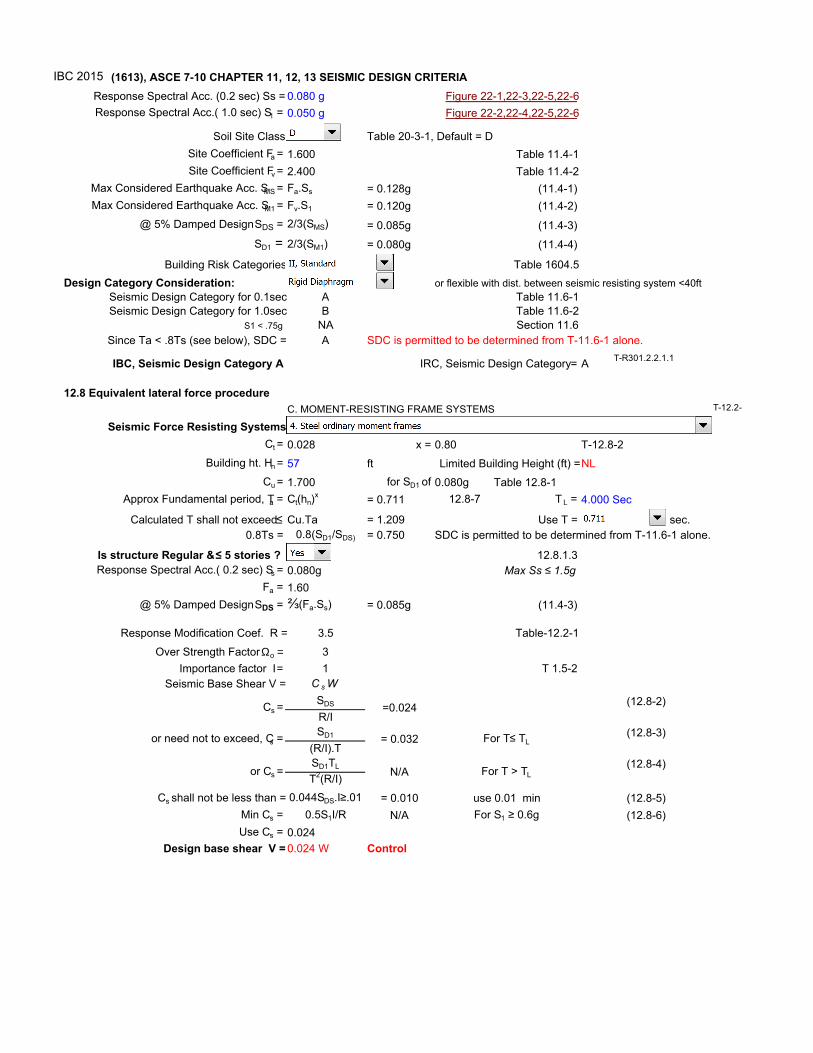
IBC2012 (1613), ASCE 710 CHAPTER 11, 12, 13 SEISMIC DESIGN CRITERIA
Response Spectral Acc. (0.2 sec) Ss = 0.080 g Figure 221,223,225,226
Response Spectral Acc.( 1.0 sec) S1 = 0.050 g Figure 222,224,225,226
Soil Site Class Table 2031, Default = D
Site Coefficient Fa = 1.600 Table 11.41
Site Coefficient Fv = 2.400 Table 11.42
Max Considered Earthquake Acc. SMS = Fa.Ss = 0.128g (11.41)
Max Considered Earthquake Acc. SM1 = Fv.S1 = 0.120g (11.42)
@ 5% Damped Design SDS = 2/3(SMS) = 0.085g (11.43)
SD1 = 2/3(SM1) = 0.080g (11.44)
Building Risk Categories Table 1604.5
Design Category Consideration: or flexible with dist. between seismic resisting system <40ft
Seismic Design Category for 0.1sec A Table 11.61
Seismic Design Category for 1.0sec B Table 11.62
S1 < .75g NA Section 11.6
Since Ta < .8Ts (see below), SDC = A SDC is permitted to be determined from T11.61 alone.
IBC, Seismic Design Category A IRC, Seismic Design Category = A
12.8 Equivalent lateral force procedure
Seismic Force Resisting Systems
Ct = 0.028 x = 0.80 T12.82
Building ht. Hn = 57 ft Limited Building Height (ft) =NL
Cu = 1.700 for SD1 of 0.080g Table 12.81
Approx Fundamental period, Ta = Ct(hn)x
= 0.711 12.87 T L = 4.000 Sec
Calculated T shall not exceed ≤ Cu.Ta = 1.209 Use T = 0.711 sec.
0.8Ts = 0.8(SD1/SDS) = 0.750
Is structure Regular & ≤ 5 stories ? 12.8.1.3
Response Spectral Acc.( 0.2 sec) Ss = 0.080g Max Ss ≤ 1.5g
Fa = 1.60
@ 5% Damped Design SDS = ⅔(Fa.Ss) = 0.085g (11.43)
Response Modification Coef. R = 3.5 Table12.21
Over Strength Factor Ωο = 3
Importance factor I = 1 T 1.52
Seismic Base Shear V = C s W
SDS (12.82)
R/I
SD1 (12.83)
(R/I).T
SD1TL (12.84)
T2(R/I)
Cs shall not be less than = 0.044SDS.I≥.01 = 0.010 use 0.01 min (12.85)
Min Cs = 0.5S1I/R N/A For S1 ≥ 0.6g (12.86)
Use Cs = 0.024
Design base shear V = 0.024 W Control
= 0.032
C. MOMENTRESISTING FRAME SYSTEMS
SDC is permitted to be determined from T11.61 alone.
Cs = =0.024
or need not to exceed, Cs = For T≤ TL
or Cs = For T > TLN/A
T12.14
T12.2
TR301.2.2.1.1
IBC 2015

MCCARTHY ENGINEERING, INC.
Wind Analysis Calculations
ASCE 710

Project Name: HURLBURT CWSS 2
Location: Hurlburt AFB
By: Jeff McCarthy, P.E.
Start Date: 12/1/2016
Comments:
..\Calculations\WIND LOADS.wls

HURLBURT CWSS 2 December 1, 2016
ASCE7110
HURLBURT CWSS 2 December 1, 2016
ASCE7110
Local Information
Wind Dir. Exposure
1 C
2 C
3 C
4 C
Basic Wind Speed: 145 mph
Topography: None
Optional FactorsThis project uses load combinations
from ASCE 7.
WLS4 11 [1.4] Copyright © 2020 SDG, Inc. Page 1 of 11
HURLBURT CWSS 2 December 1, 2016
ASCE7110
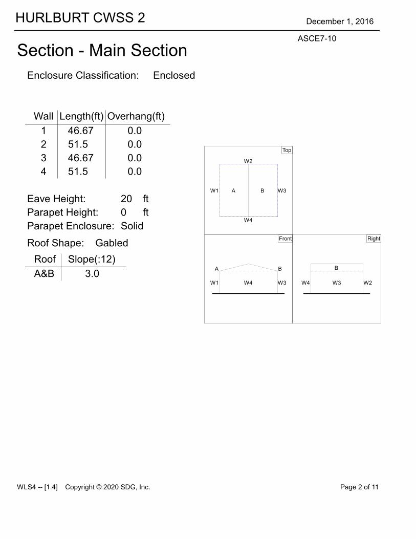
Section 1 Main Section
Enclosure Classification: Enclosed
Wall Length(ft) Overhang(ft)
1 46.67 0.0
2 51.5 0.0
3 46.67 0.0
4 51.5 0.0
Eave Height: 20 ft
Parapet Height: 0 ft
Parapet Enclosure: Solid
Roof Shape:
Roof Slope(:12)
A&B 3.0
Gabled
Top
W1
W2
W3
W4
A B
Front
W3W4W1
A B
Right
W2W3W4
B
WLS4 11 [1.4] Copyright © 2020 SDG, Inc. Page 2 of 11

HURLBURT CWSS 2 December 1, 2016
ASCE7110
Enclosure Classifications
Wind Dir Wall # Ao(sqft) Ag(sqft) Aoi(sqft) Agi(sqft)
1 1 0.0 3640.0 0.0 5442.2
0.0 2000.0
2 2 0.0 700.0 0.0 5342.2
0.0 1020.0
3 3 0.0 7050.0 0.0 5442.2
0.0 2000.0
4 4 0.0 1275.0 0.0 5342.2
Roof 0.0 15846.7
WLS4 11 [1.4] Copyright © 2020 SDG, Inc. Page 3 of 11

HURLBURT CWSS 2 December 1, 2016
ASCE7110
Composite Drawing
1
2
3
4
1
2
3
4
A B
WLS4 11 [1.4] Copyright © 2020 SDG, Inc. Page 4 of 11

HURLBURT CWSS 2 December 1, 2016
ASCE7110
Components and Cladding Input
Component Description Wall/Roof Surface Label Zone Span(ft) Width(ft) Area(sqft)
ROOF 10 SF Roof A (All) 2.0 5.0 10
ROOF 20 SF Roof A (All) 5.0 4.0 20
ROOF 50 SF Roof A (All) 5.0 10.0 50
ROOF 100 SF Roof A (All) 10.0 10.0 100
WALL 10 SF Wall 1 (All) 2.0 5.0 10.0
WALL 20 SF Wall 1 (All) 4.0 5.0 20.0
WALL 50 SF Wall 1 (All) 5.0 10.0 50.0
WALL 100 SF Wall 1 (All) 10.0 10.0 100.0
WLS4 11 [1.4] Copyright © 2020 SDG, Inc. Page 5 of 11

HURLBURT CWSS 2 December 1, 2016
ASCE7110
Components and Cladding Output
Component Description Surface Zone z(ft) q(psf) GCp GCpi ExtPres(psf) Net w/ +GCpi (psf) Net w/ 1GCpi (psf)
ROOF 10 SF A 1 23.2 42.6 0.50 0.18 21.3 13.6 29.0
23.2 42.6 10.90 138.3 146.0 130.7
2 23.2 42.6 0.50 21.3 13.6 29.0
23.2 42.6 11.70 172.4 180.1 164.8
3 23.2 42.6 0.50 21.3 13.6 29.0
23.2 42.6 12.60 1110.8 1118.4 1103.1
ROOF 20 SF A 1 23.2 42.6 0.44 0.18 18.7 11.1 26.4
23.2 42.6 10.87 137.1 144.7 129.4
2 23.2 42.6 0.44 18.7 11.1 26.4
23.2 42.6 11.55 166.0 173.7 158.4
3 23.2 42.6 0.44 18.7 11.1 26.4
23.2 42.6 12.42 1103.1 1110.8 195.4
ROOF 50 SF A 1 23.2 42.6 0.36 0.18 15.3 7.7 23.0
23.2 42.6 10.83 135.4 143.0 127.7
2 23.2 42.6 0.36 15.3 7.7 23.0
23.2 42.6 11.35 157.5 165.2 149.8
3 23.2 42.6 0.36 15.3 7.7 23.0
23.2 42.6 12.18 192.9 1100.5 185.2
ROOF 100 SF A 1 23.2 42.6 0.30 0.18 12.8 5.1 20.4
23.2 42.6 10.80 134.1 141.7 126.4
2 23.2 42.6 0.30 12.8 5.1 20.4
23.2 42.6 11.20 151.1 158.8 143.5
3 23.2 42.6 0.30 12.8 5.1 20.4
23.2 42.6 12.00 185.2 192.9 177.5
WALL 10 SF 1 4 23.2 42.6 1.00 0.18 42.6 34.9 50.3
23.2 42.6 11.10 146.9 154.5 139.2
5 23.2 42.6 1.00 42.6 34.9 50.3
23.2 42.6 11.40 159.6 167.3 152.0
WALL 20 SF 1 4 23.2 42.6 0.95 0.18 40.5 32.8 48.1
23.2 42.6 11.05 144.7 152.4 137.1
5 23.2 42.6 0.95 40.5 32.8 48.1
WLS4 11 [1.4] Copyright © 2020 SDG, Inc. Page 6 of 11

HURLBURT CWSS 2 December 1, 2016
ASCE7110
Components and Cladding Output
Component Description Surface Zone z(ft) q(psf) GCp GCpi ExtPres(psf) Net w/ +GCpi (psf) Net w/ 1GCpi (psf)
WALL 20 SF 1 5 23.2 42.6 11.29 0.18 155.0 162.6 147.3
WALL 50 SF 1 4 23.2 42.6 0.88 0.18 37.5 29.8 45.2
23.2 42.6 10.98 141.7 149.4 134.1
5 23.2 42.6 0.88 37.5 29.8 45.2
23.2 42.6 11.15 149.0 156.7 141.3
WALL 100 SF 1 4 23.2 42.6 0.82 0.18 34.9 27.3 42.6
23.2 42.6 10.92 139.2 146.9 131.5
5 23.2 42.6 0.82 34.9 27.3 42.6
23.2 42.6 11.05 144.7 152.4 137.1
WLS4 11 [1.4] Copyright © 2020 SDG, Inc. Page 7 of 11

HURLBURT CWSS 2 December 1, 2016
ASCE7110
MWFRS Net PressuresThis data was calculated using the building of all heights method.
Wind Direction 1
# Surface z (ft) q (psf) G Cp GCpi Ext Pres (psf) Net w/ +GCpi (psf) Net w/ 1GCpi (psf)
1 Windward Wall 15.0 38.8 0.89 0.80 0.18 27.6 20.0 35.3
20.0 41.3 0.80 29.4 21.7 37.1
2 Side Wall 23.2 42.6 0.89 10.70 0.18 126.5 134.2 118.9
3 Leeward Wall 23.2 42.6 0.89 10.48 0.18 118.2 125.9 110.5
4 Side Wall 23.2 42.6 0.89 10.70 0.18 126.5 134.2 118.9
A Windward Roof 23.2 42.6 0.89 10.15 0.18 15.7 113.4 2.0
23.2 42.6 10.70 126.5 134.2 118.9
B Leeward Roof 23.2 42.6 0.89 10.49 0.18 118.6 126.2 110.9
This is load case 1 in ASCE 7110 Figure 27.418. See Figure 27.418 for other cases.
WLS4 11 [1.4] Copyright © 2020 SDG, Inc. Page 8 of 11
MWFRS WALL = 47.6 PSFMWFRS ROOF = 34.2 PSF

HURLBURT CWSS 2 December 1, 2016
ASCE7110
MWFRS Net PressuresThis data was calculated using the building of all heights method.
Wind Direction 2
# Surface z (ft) q (psf) G Cp GCpi Ext Pres (psf) Net w/ +GCpi (psf) Net w/ 1GCpi (psf)
1 Side Wall 23.2 42.6 0.89 10.70 0.18 126.5 134.2 118.9
2 Windward Wall 15.0 38.8 0.80 27.6 20.0 35.3
20.0 41.3 0.80 29.4 21.7 37.1
23.2 42.6 0.80 30.3 22.7 38.0
25.0 43.2 0.80 30.8 23.1 38.4
26.4 43.8 0.80 31.2 23.5 38.9
3 Side Wall 23.2 42.6 0.89 10.70 0.18 126.5 134.2 118.9
4 Leeward Wall 23.2 42.6 0.89 10.50 0.18 119.0 126.6 111.3
A&B Roof 0 to 11.6 * 42.6 0.89 10.90 0.18 134.1 141.8 126.5
11.6 to 23.2 * 42.6 10.90 134.1 141.8 126.5
23.2 to 46.4 * 42.6 10.50 119.0 126.6 111.3
46.4 to 46.7 * 42.6 10.30 111.4 119.0 13.7
0 to 46.7 * 42.6 10.18 16.8 114.5 0.8
This is load case 1 in ASCE 7110 Figure 27.418. See Figure 27.418 for other cases.
* Distance from windward edge.
WLS4 11 [1.4] Copyright © 2020 SDG, Inc. Page 9 of 11

HURLBURT CWSS 2 December 1, 2016
ASCE7110
MWFRS Net PressuresThis data was calculated using the building of all heights method.
Wind Direction 3
# Surface z (ft) q (psf) G Cp GCpi Ext Pres (psf) Net w/ +GCpi (psf) Net w/ 1GCpi (psf)
1 Leeward Wall 23.2 42.6 0.89 10.48 0.18 118.2 125.9 110.5
2 Side Wall 23.2 42.6 10.70 126.5 134.2 118.9
3 Windward Wall 15.0 38.8 0.89 0.80 0.18 27.6 20.0 35.3
20.0 41.3 0.80 29.4 21.7 37.1
4 Side Wall 23.2 42.6 0.89 10.70 0.18 126.5 134.2 118.9
B Windward Roof 23.2 42.6 0.89 10.15 0.18 15.7 113.4 2.0
23.2 42.6 10.70 126.5 134.2 118.9
A Leeward Roof 23.2 42.6 0.89 10.49 0.18 118.6 126.2 110.9
This is load case 1 in ASCE 7110 Figure 27.418. See Figure 27.418 for other cases.
WLS4 11 [1.4] Copyright © 2020 SDG, Inc. Page 10 of 11

HURLBURT CWSS 2 December 1, 2016
ASCE7110
MWFRS Net PressuresThis data was calculated using the building of all heights method.
Wind Direction 4
# Surface z (ft) q (psf) G Cp GCpi Ext Pres (psf) Net w/ +GCpi (psf) Net w/ 1GCpi (psf)
1 Side Wall 23.2 42.6 0.89 10.70 0.18 126.5 134.2 118.9
2 Leeward Wall 23.2 42.6 10.50 119.0 126.6 111.3
3 Side Wall 23.2 42.6 0.89 10.70 0.18 126.5 134.2 118.9
4 Windward Wall 15.0 38.8 0.89 0.80 0.18 27.6 20.0 35.3
20.0 41.3 0.80 29.4 21.7 37.1
23.2 42.6 0.80 30.3 22.7 38.0
25.0 43.2 0.80 30.8 23.1 38.4
26.4 43.8 0.80 31.2 23.5 38.9
A&B Roof 0 to 11.6 * 42.6 0.89 10.90 0.18 134.1 141.8 126.5
11.6 to 23.2 * 42.6 10.90 134.1 141.8 126.5
23.2 to 46.4 * 42.6 10.50 119.0 126.6 111.3
46.4 to 46.7 * 42.6 10.30 111.4 119.0 13.7
0 to 46.7 * 42.6 10.18 16.8 114.5 0.8
This is load case 1 in ASCE 7110 Figure 27.418. See Figure 27.418 for other cases.
* Distance from windward edge.
WLS4 11 [1.4] Copyright © 2020 SDG, Inc. Page 11 of 11

CIVIL DESIGN ANALYSIS

CONSTRUCT TRAINING FACILITY 2 CWSS BLD 91068 FTEV 16-1066 HURLBURT FIELD, FL FA4417-16-R-0025
CIVIL DESIGN ANALYSIS 1
CIVIL DESIGN ANALYSIS FINAL SUBMITTAL
Scope of Work: Civil, sitework & site utilities design to support construction of the “Training Facility 2 CSWW” project at Hurlburt Field. Environmental: No assertions are made by the designer as to the existence or non-existence of any environmental encumbrances on the site. No environmental audit of existing site conditions is within the scope of this contract. No water or sewer permits are anticipated as the project will entail services to a single building. Topographical Survey: The sitework design was completed based upon a topographic survey provided by Emerald Coast Associates, Inc. Stormwater Pollution Prevention: Silt fences sediment barriers will be incorporated into the design to prevent sediment migration off-site. These measures will be depicted on the Existing Conditions and Demolition Plan. No NPDES permit form for “Discharge of Stormwater During Construction Activity” should be required as the overall impacted area is less than one acre. Water Service: A 6” water service to the building for both fire and domestic services is provided by connection to an existing water main near the northwest corner of the building. Sanitary Sewer: A new sanitary sewer lateral will be installed connecting to the existing gravity sanitary sewer northwest of the building location. Stormwater: The project site is located within a drainage basin that has already been permitted under Florida Administrative Code Rule 62-25 for stormwater treatment via a swale exemption. No new stormwater treatment will be required. A repair to the existing swale system will be required to achieve original design intent. An As-Built Certification for the swale exemption will be submitted.

MECHANICAL DESIGN ANALYSIS

CONSTRUCT TRAINING FACILITY, 2 CSWW, BLDG. 91038 FTEV 16-1066 HURLBURT FIELD, FLORIDA
MECHANICAL DESIGN ANALYSIS 1
MECHANICAL DESIGN ANALYSIS FINAL SUBMITTAL
CODES AND REFERENCES
• The International Mechanical Code
• The International Building Code
• ASHRAE Standard 62.1 - 2010 “Ventilation for Acceptable Indoor Air Quality”
• ASHRAE 90.1 - 2010 “Energy Standard for Buildings Except Low-Rise Residential Buildings”
• ASHRAE 55-2004
• UFC 3-410-01-FA Design: Heating, Ventilating, and Air Conditioning
MECHANICAL - SYSTEM DESCRIPTION
The new training facility will have three separate air conditioning zones. The first zone is to be for
the training room. The training room consists of 20 occupants, with laptops, a smartboard, and a
large monitor. This area will be served by a single zone direct expansion heat pump air
conditioning system. The second zone will consist of three offices, a hallway, and a conference
room. This area will also be served by a single zone direct expansion heat pump air conditioning
system. The third zone is a semi-server room, that consists of rack servers, switches, and about
10 computers. There will be room for 6 occupants to work. This area will be served by two
mini-split AC units that will be mounted on the south wall.
The first two heat pumps, serving the training area and the conference area, will be installed inside
the mechanical room, in the northwest quadrant of the building. Condensate will be evacuated via
a drain in the mech room floor. The outdoor heat pump units will sit on a concrete pad, and the
refrigerant piping is to be ran underground. The outdoor units that serve the mini-split units are
to be mounted atop of a concrete pad just south of the walk way that surrounds the new building.
Condensate and refrigerant piping is to be routed underground, and condensate to be routed to a
dry well.

CONSTRUCT TRAINING FACILITY, 2 CSWW FTEV 16-1066 HURLBURT FIELD, FLORIDA
MECHANICAL DESIGN ANALYSIS
MECHANICAL CALCULATIONS

AHU-1 Training Input DataProject Name: 16132 - Training and Testing 12/01/2016 Prepared by: Peterson Engineering Inc 01:40PM
1. General Details: Air System Name AHU-1 Training Equipment Type Split AHU Air System Type Single Zone CAV Number of zones 1
2. Ventilation System Components:Ventilation Air Data: Airflow Control Constant Ventilation Airflow Ventilation Sizing Method ASHRAE Std 62.1-2013 Unocc. Damper Position Closed Damper Leak Rate 0 % Outdoor Air CO2 Level 400 ppm
Dehumidification Data: Maximum RH Setpoint 50 %
Central Cooling Data: Supply Airflow Rate 1020.0 CFM Coil Bypass Factor 0.100 Cooling Source Air-Cooled DX Schedule JFMAMJJASOND Capacity Control Cycled or Staged Capacity - Fan On
Central Heating Data: Supply Temperature 95.0 °F Heating Source Electric Resistance Schedule JFMAMJJASOND Capacity Control Cycled or Staged Capacity - Fan On
Supply Fan Data: Fan Type Forward Curved Configuration Draw-thru Fan Performance 0.50 in wg Overall Efficiency 54 % Fan Control 1-speed fan, cooling and heating
Duct System Data: Supply Duct Data: Duct Heat Gain 5 % Duct Leakage 5 %
Return Duct or Plenum Data: Return Air Via Ducted Return
3. Zone Components:Space Assignments:
Zone 1: Zone 1 Training Rm 109 x1
Thermostats and Zone Data: Zone All Cooling T-stat: Occ. 75.0 °F Cooling T-stat: Unocc. 80.0 °F Heating T-stat: Occ. 70.0 °F Heating T-stat: Unocc. 65.0 °F T-stat Throttling Range 4.00 °F Diversity Factor 100 % Direct Exhaust Airflow 0.0 CFM Direct Exhaust Fan kW 0.0 kW
Thermostat Schedule OCC Unoccupied Cooling is Available
Supply Terminals Data: Zone All Terminal Type Diffuser Minimum Airflow 0.00 CFM/person
Zone Heating Units:
Hourly Analysis Program v5.00 Page 1 of 2

AHU-1 Training Input DataProject Name: 16132 - Training and Testing 12/01/2016 Prepared by: Peterson Engineering Inc 01:40PM
Zone All Zone Heating Unit Type None
Zone Unit Heat Source Electric Resistance Zone Heating Unit Schedule JFMAMJJASOND
4. Sizing Data (Computer-Generated):System Sizing Data: Sizing Data: Cooling Supply Temperature 60.7 °F Supply Fan Airflow 1020.0 CFM Ventilation Airflow 187.6 CFM Heating Supply Temperature 95.0 °F
Hydronic Sizing Specifications: Chilled Water Delta-T 10.0 °F Hot Water Delta-T 20.0 °F
Safety Factors: Cooling Sensible 10 % Cooling Latent 10 % Heating 10 %
Zone Sizing Data: Zone Airflow Sizing Method Sum of space airflow rates Space Airflow Sizing Method Individual peak space loads
Zone Supply Airflow Zone Htg Unit Reheat Coil - (CFM) (MBH) (MBH) (CFM)
1 969.0 - -
5. Equipment DataCentral Cooling Unit - Air-Cooled DX Estimated Maximum Load 36.3 MBH Design OAT 95.0 °F Equipment Sizing Auto-Sized Capacity Oversizing Factor 0 % ARI Performance Rating 11.000 EER DX System Configuration 1-stage compression, 1 circuit Conventional Cutoff OAT 55.0 °F Low Temperature Operation Used Low Temperature Cutoff OAT 0.0 °F
Hourly Analysis Program v5.00 Page 2 of 2

Air System Sizing Summary for AHU-1 TrainingProject Name: 16132 - Training and Testing 12/01/2016 Prepared by: Peterson Engineering Inc 01:38PM
Air System Information Air System Name AHU-1 Training Equipment Class SPLT AHU Air System Type SZCAV
Number of zones 1Floor Area 835.0 ft²Location Hurlburt Field, Florida
Sizing Calculation Information Calculation Months Jan to Dec Sizing Data Calculated
Zone CFM Sizing Sum of space airflow ratesSpace CFM Sizing Individual peak space loads
Central Cooling Coil Sizing Data Total coil load 3.0 Tons Total coil load 36.3 MBH Sensible coil load 25.7 MBH Coil CFM at Jun 1500 1020 CFM Max block CFM 1020 CFM Sum of peak zone CFM 1020 CFM Sensible heat ratio 0.708 ft²/Ton 275.7 BTU/(hr·ft²) 43.5 Water flow @ 10.0 °F rise N/A
Load occurs at Jun 1500OA DB / WB 94.0 / 78.0 °FEntering DB / WB 80.3 / 67.4 °FLeaving DB / WB 56.9 / 55.8 °FCoil ADP 54.4 °FBypass Factor 0.100Resulting RH 50 %Design supply temp. 60.7 °FZone T-stat Check 1 of 1 OKMax zone temperature deviation 0.0 °F
Central Heating Coil Sizing Data Max coil load 11.7 MBH Coil CFM at Des Htg 1020 CFM Max coil CFM 1020 CFM Water flow @ 20.0 °F drop N/A
Load occurs at Des HtgBTU/(hr·ft²) 14.0Ent. DB / Lvg DB 61.5 / 72.1 °F
Supply Fan Sizing Data Actual max CFM 1020 CFM Standard CFM 1019 CFM Actual max CFM/ft² 1.22 CFM/ft²
Fan motor BHP 0.14 BHPFan motor kW 0.11 kWFan static 0.50 in wg
Outdoor Ventilation Air Data Design airflow CFM 188 CFM CFM/ft² 0.22 CFM/ft²
CFM/person 9.38 CFM/person
Hourly Analysis Program v5.00 Page 1 of 8

Zone Sizing Summary for AHU-1 TrainingProject Name: 16132 - Training and Testing 12/01/2016 Prepared by: Peterson Engineering Inc 01:38PM
Air System Information Air System Name AHU-1 Training Equipment Class SPLT AHU Air System Type SZCAV
Number of zones 1Floor Area 835.0 ft²Location Hurlburt Field, Florida
Sizing Calculation Information Calculation Months Jan to Dec Sizing Data Calculated
Zone CFM Sizing Sum of space airflow ratesSpace CFM Sizing Individual peak space loads
Zone Terminal Sizing Data
Zone Name
DesignSupplyAirflow(CFM)
MinimumSupplyAirflow(CFM)
ZoneCFM/ft²
ReheatCoilLoad
(MBH)
ReheatCoil
Watergpm
@ 20.0 °F
ZoneHtg Unit
CoilLoad
(MBH)
ZoneHtg UnitWatergpm
@ 20.0 °F
MixingBox FanAirflow(CFM)
Zone 1 969 969 1.16 0.0 - 0.0 - 0
Zone Peak Sensible Loads
Zone Zone Zone Cooling Time of Heating Floor
Sensible Peak Sensible Load AreaZone Name (MBH) Cooling Load (MBH) (ft²)
Zone 1 15.0 Jul 1300 3.2 835.0
Space Loads and Airflows
Zone Name / Space Name Mult.
CoolingSensible
(MBH)
Time ofPeak
SensibleLoad
AirFlow(CFM)
HeatingLoad
(MBH)
FloorArea(ft²)
SpaceCFM/ft²
Zone 1 Training Rm 109 1 15.0 Jul 1300 969 3.2 835.0 1.16
Hourly Analysis Program v5.00 Page 2 of 8

Ventilation Sizing Summary for AHU-1 TrainingProject Name: 16132 - Training and Testing 12/01/2016 Prepared by: Peterson Engineering Inc 01:38PM
1. Summary Ventilation Sizing Method ASHRAE Std 62.1-2013 Design Condition Heating operation Occupant Diversity (D) 1.000 Uncorrected Outdoor Air Intake (Vou) 150 CFM System Ventilation Efficiency (Ev) 1.000 Outdoor Air Intake (Vot) 188 CFM
2. Space Ventilation Analysis
Supply Air
(CFM)
Space Floor Area(ft²)
Area Outdoor Air Rate
(CFM/ft²)
Time Averaged
Occupancy(Occupants)
People Outdoor Air
Rate(CFM/person)
Air Distribution
Effectiveness
Space Outdoor Air
(CFM)
Breathing Zone Outdoor
Air(CFM)
Space Ventilation Efficiency
Zone Name / Space Name Mult. (Vpz) (Az) (Ra) (Pz) (Rp) (Ez) (Voz) (Vbz) (Evz)
Zone 1
Training Rm 109 1 969 835.0 0.06 20.0 5.00 0.80 188 150 1.000Totals (incl. Space Multipliers) 969 150 1.000
Hourly Analysis Program v5.00 Page 3 of 8

Air System Design Load Summary for AHU-1 TrainingProject Name: 16132 - Training and Testing 12/01/2016 Prepared by: Peterson Engineering Inc 01:38PM
DESIGN COOLING DESIGN HEATING
COOLING DATA AT Jun 1500 HEATING DATA AT DES HTG COOLING OA DB / WB 94.0 °F / 78.0 °F HEATING OA DB / WB 25.0 °F / 23.6 °F
Sensible Latent Sensible LatentZONE LOADS Details (BTU/hr) (BTU/hr) Details (BTU/hr) (BTU/hr)
Window & Skylight Solar Loads 0 ft² 0 - 0 ft² - -Wall Transmission 578 ft² 560 - 578 ft² 1151 -Roof Transmission 880 ft² 1349 - 880 ft² 1198 -Window Transmission 0 ft² 0 - 0 ft² 0 -Skylight Transmission 0 ft² 0 - 0 ft² 0 -Door Loads 18 ft² 190 - 18 ft² 527 -Floor Transmission 835 ft² 0 - 835 ft² 0 -Partitions 0 ft² 0 - 0 ft² 0 -Ceiling 0 ft² 0 - 0 ft² 0 -Overhead Lighting 835 W 2849 - 0 0 -Task Lighting 0 W 0 - 0 0 -Electric Equipment 1060 W 3617 - 0 0 -People 20 4900 4100 0 0 0Infiltration - 0 0 - 0 0Miscellaneous - 0 0 - 0 0Safety Factor 10% / 10% 1346 410 10% 288 0>> Total Zone Loads - 14811 4510 - 3163 0
Zone Conditioning - 13989 4510 - 2842 0Plenum Wall Load 0% 0 - 0 0 -Plenum Roof Load 0% 0 - 0 0 -Plenum Lighting Load 0% 0 - 0 0 -Return Fan Load 1020 CFM 0 - 1020 CFM 0 -Ventilation Load 188 CFM 3391 6107 188 CFM 9048 0Supply Fan Load 1020 CFM 378 - 1020 CFM -378 -Space Fan Coil Fans - 0 - - 0 -Duct Heat Gain / Loss 5% 741 - 5% 158 ->> Total System Loads - 18499 10617 - 11670 0
Central Cooling Coil - 25727 10617 - 0 0Central Heating Coil - -7229 - - 11670 ->> Total Conditioning - 18499 10617 - 11670 0
Key: Positive values are clg loads Positive values are htg loads Negative values are htg loads Negative values are clg loads
Hourly Analysis Program v5.00 Page 4 of 8

Zone Design Load Summary for AHU-1 TrainingProject Name: 16132 - Training and Testing 12/01/2016 Prepared by: Peterson Engineering Inc 01:38PM
Zone 1 DESIGN COOLING DESIGN HEATING
COOLING DATA AT Jul 1300 HEATING DATA AT DES HTG COOLING OA DB / WB 93.3 °F / 77.6 °F HEATING OA DB / WB 25.0 °F / 23.6 °F
OCCUPIED T-STAT 75.0 °F OCCUPIED T-STAT 70.0 °F
Sensible Latent Sensible LatentZONE LOADS Details (BTU/hr) (BTU/hr) Details (BTU/hr) (BTU/hr)
Window & Skylight Solar Loads 0 ft² 0 - 0 ft² - -Wall Transmission 578 ft² 538 - 578 ft² 1151 -Roof Transmission 880 ft² 1535 - 880 ft² 1198 -Window Transmission 0 ft² 0 - 0 ft² 0 -Skylight Transmission 0 ft² 0 - 0 ft² 0 -Door Loads 18 ft² 184 - 18 ft² 527 -Floor Transmission 835 ft² 0 - 835 ft² 0 -Partitions 0 ft² 0 - 0 ft² 0 -Ceiling 0 ft² 0 - 0 ft² 0 -Overhead Lighting 835 W 2849 - 0 0 -Task Lighting 0 W 0 - 0 0 -Electric Equipment 1060 W 3617 - 0 0 -People 20 4900 4100 0 0 0Infiltration - 0 0 - 0 0Miscellaneous - 0 0 - 0 0Safety Factor 10% / 10% 1362 410 10% 288 0>> Total Zone Loads - 14985 4510 - 3163 0
Hourly Analysis Program v5.00 Page 5 of 8
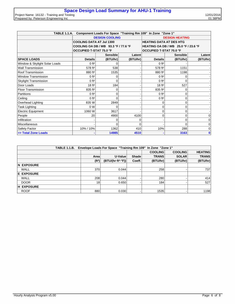
Space Design Load Summary for AHU-1 TrainingProject Name: 16132 - Training and Testing 12/01/2016 Prepared by: Peterson Engineering Inc 01:38PM
TABLE 1.1.A. Component Loads For Space "Training Rm 109" In Zone "Zone 1"
DESIGN COOLING DESIGN HEATING
COOLING DATA AT Jul 1300 HEATING DATA AT DES HTG
COOLING OA DB / WB 93.3 °F / 77.6 °F HEATING OA DB / WB 25.0 °F / 23.6 °F
OCCUPIED T-STAT 75.0 °F OCCUPIED T-STAT 70.0 °F
Sensible Latent Sensible Latent
SPACE LOADS Details (BTU/hr) (BTU/hr) Details (BTU/hr) (BTU/hr)
Window & Skylight Solar Loads 0 ft² 0 - 0 ft² - -Wall Transmission 578 ft² 538 - 578 ft² 1151 -Roof Transmission 880 ft² 1535 - 880 ft² 1198 -Window Transmission 0 ft² 0 - 0 ft² 0 -Skylight Transmission 0 ft² 0 - 0 ft² 0 -Door Loads 18 ft² 184 - 18 ft² 527 -Floor Transmission 835 ft² 0 - 835 ft² 0 -Partitions 0 ft² 0 - 0 ft² 0 -Ceiling 0 ft² 0 - 0 ft² 0 -Overhead Lighting 835 W 2849 - 0 0 -Task Lighting 0 W 0 - 0 0 -Electric Equipment 1060 W 3617 - 0 0 -People 20 4900 4100 0 0 0Infiltration - 0 0 - 0 0Miscellaneous - 0 0 - 0 0Safety Factor 10% / 10% 1362 410 10% 288 0>> Total Zone Loads - 14985 4510 - 3163 0
TABLE 1.1.B. Envelope Loads For Space "Training Rm 109" In Zone "Zone 1"
COOLING COOLING HEATING
Area U-Value Shade TRANS SOLAR TRANS
(ft²) (BTU/(hr·ft²·°F)) Coeff. (BTU/hr) (BTU/hr) (BTU/hr)
N EXPOSURE WALL 370 0.044 - 258 - 737E EXPOSURE WALL 208 0.044 - 280 - 414 DOOR 18 0.650 - 184 - 527H EXPOSURE ROOF 880 0.030 - 1535 - 1198
Hourly Analysis Program v5.00 Page 6 of 8

System Psychrometrics for AHU-1 TrainingProject Name: 16132 - Training and Testing 12/01/2016 Prepared by: Peterson Engineering Inc 01:38PM
June DESIGN COOLING DAY, 1500
TABLE 1: SYSTEM DATA
Dry-Bulb Specific Sensible Latent Temp Humidity Airflow CO2 Level Heat HeatComponent Location (°F) (lb/lb) (CFM) (ppm) (BTU/hr) (BTU/hr)Ventilation Air Inlet 94.0 0.01702 188 400 3391 6107Vent - Return Mixing Outlet 80.3 0.01142 1020 1406 - -Central Cooling Coil Outlet 56.9 0.00923 1020 1406 25727 10617Central Heating Coil Outlet 63.5 0.00923 1020 1406 7229 -Supply Fan Outlet 63.9 0.00923 1020 1406 378 -Cold Supply Duct Outlet 64.6 0.00923 969 1406 - -Zone Air - 78.0 0.01021 969 1645 13989 4510Return Plenum Outlet 78.0 0.01021 969 1645 0 -Duct Leakage Air Outlet 63.9 0.00923 51 1406 - -Return Duct Outlet 77.2 0.01016 1020 1633 - -
Air Density x Heat Capacity x Conversion Factor: At sea level = 1.080; At site altitude = 1.079 BTU/(hr-CFM-F) Air Density x Heat of Vaporization x Conversion Factor: At sea level = 4746.6; At site altitude = 4741.5 BTU/(hr-CFM) Site Altitude = 30.0 ft
TABLE 2: ZONE DATA
Zone Terminal Zone Sensible Zone Zone Zone CO2 Heating Heating Load T-stat Cond Temp Airflow Level Coil UnitZone Name (BTU/hr) Mode (BTU/hr) (°F) (CFM) (ppm) (BTU/hr) (BTU/hr)Zone 1 14811 Cooling 13989 78.0 969 1645 0 0
Hourly Analysis Program v5.00 Page 7 of 8
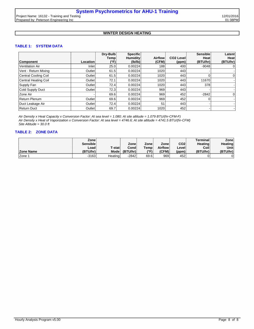
System Psychrometrics for AHU-1 TrainingProject Name: 16132 - Training and Testing 12/01/2016 Prepared by: Peterson Engineering Inc 01:38PM
WINTER DESIGN HEATING
TABLE 1: SYSTEM DATA
Dry-Bulb Specific Sensible Latent Temp Humidity Airflow CO2 Level Heat HeatComponent Location (°F) (lb/lb) (CFM) (ppm) (BTU/hr) (BTU/hr)Ventilation Air Inlet 25.0 0.00224 188 400 -9048 0Vent - Return Mixing Outlet 61.5 0.00224 1020 443 - -Central Cooling Coil Outlet 61.5 0.00224 1020 443 0 0Central Heating Coil Outlet 72.1 0.00224 1020 443 11670 -Supply Fan Outlet 72.4 0.00224 1020 443 378 -Cold Supply Duct Outlet 72.3 0.00224 969 443 - -Zone Air - 69.6 0.00224 969 452 -2842 0Return Plenum Outlet 69.6 0.00224 969 452 0 -Duct Leakage Air Outlet 72.4 0.00224 51 443 - -Return Duct Outlet 69.7 0.00224 1020 452 - -
Air Density x Heat Capacity x Conversion Factor: At sea level = 1.080; At site altitude = 1.079 BTU/(hr-CFM-F) Air Density x Heat of Vaporization x Conversion Factor: At sea level = 4746.6; At site altitude = 4741.5 BTU/(hr-CFM) Site Altitude = 30.0 ft
TABLE 2: ZONE DATA
Zone Terminal Zone Sensible Zone Zone Zone CO2 Heating Heating Load T-stat Cond Temp Airflow Level Coil UnitZone Name (BTU/hr) Mode (BTU/hr) (°F) (CFM) (ppm) (BTU/hr) (BTU/hr)Zone 1 -3163 Heating -2842 69.6 969 452 0 0
Hourly Analysis Program v5.00 Page 8 of 8

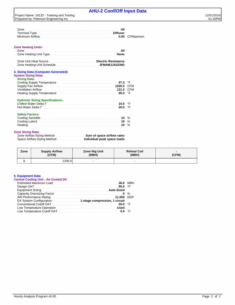
AHU-2 Conf/Off Input DataProject Name: 16132 - Training and Testing 12/01/2016 Prepared by: Peterson Engineering Inc 01:40PM
1. General Details: Air System Name AHU-2 Conf/Off Equipment Type Split AHU Air System Type Single Zone CAV Number of zones 1
2. Ventilation System Components:Ventilation Air Data: Airflow Control Constant Ventilation Airflow Ventilation Sizing Method Sum of Space OA Airflows Unocc. Damper Position Closed Damper Leak Rate 0 % Outdoor Air CO2 Level 400 ppm
Dehumidification Data: Maximum RH Setpoint 50 %
Central Cooling Data: Supply Airflow Rate 1200.0 CFM Coil Bypass Factor 0.100 Cooling Source Air-Cooled DX Schedule JFMAMJJASOND Capacity Control Cycled or Staged Capacity - Fan On
Central Heating Data: Supply Temperature 95.0 °F Heating Source Electric Resistance Schedule JFMAMJJASOND Capacity Control Cycled or Staged Capacity - Fan On
Supply Fan Data: Fan Type Forward Curved Configuration Draw-thru Fan Performance 0.70 in wg Overall Efficiency 54 % Fan Control 1-speed fan, cooling and heating
Duct System Data: Supply Duct Data: Duct Heat Gain 0 % Duct Leakage 0 %
Return Duct or Plenum Data: Return Air Via Ducted Return
3. Zone Components:Space Assignments:
Zone 1: Zone 1 Conference x1Office 106 x1Office 104 x1Office 105 x1Entry 101 x1Unisex Tlt x1
Thermostats and Zone Data: Zone All Cooling T-stat: Occ. 75.0 °F Cooling T-stat: Unocc. 80.0 °F Heating T-stat: Occ. 70.0 °F Heating T-stat: Unocc. 65.0 °F T-stat Throttling Range 2.00 °F Diversity Factor 100 % Direct Exhaust Airflow 100.0 CFM Direct Exhaust Fan kW 0.3 kW
Thermostat Schedule OCC Unoccupied Cooling is Available
Supply Terminals Data:
Hourly Analysis Program v5.00 Page 1 of 2
AHU-2 Conf/Off Input DataProject Name: 16132 - Training and Testing 12/01/2016 Prepared by: Peterson Engineering Inc 01:40PM
Zone All Terminal Type Diffuser Minimum Airflow 0.00 CFM/person
Zone Heating Units: Zone All Zone Heating Unit Type None
Zone Unit Heat Source Electric Resistance Zone Heating Unit Schedule JFMAMJJASOND
4. Sizing Data (Computer-Generated):System Sizing Data: Sizing Data: Cooling Supply Temperature 57.3 °F Supply Fan Airflow 1200.0 CFM Ventilation Airflow 131.3 CFM Heating Supply Temperature 95.0 °F
Hydronic Sizing Specifications: Chilled Water Delta-T 10.0 °F Hot Water Delta-T 20.0 °F
Safety Factors: Cooling Sensible 10 % Cooling Latent 10 % Heating 10 %
Zone Sizing Data: Zone Airflow Sizing Method Sum of space airflow rates Space Airflow Sizing Method Individual peak space loads
Zone Supply Airflow Zone Htg Unit Reheat Coil - (CFM) (MBH) (MBH) (CFM)
1 1200.0 - -
5. Equipment DataCentral Cooling Unit - Air-Cooled DX Estimated Maximum Load 36.6 MBH Design OAT 95.0 °F Equipment Sizing Auto-Sized Capacity Oversizing Factor 0 % ARI Performance Rating 11.000 EER DX System Configuration 1-stage compression, 1 circuit Conventional Cutoff OAT 55.0 °F Low Temperature Operation Used Low Temperature Cutoff OAT 0.0 °F
Hourly Analysis Program v5.00 Page 2 of 2
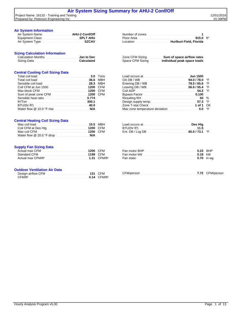
Air System Sizing Summary for AHU-2 Conf/OffProject Name: 16132 - Training and Testing 12/01/2016 Prepared by: Peterson Engineering Inc 01:39PM
Air System Information Air System Name AHU-2 Conf/Off Equipment Class SPLT AHU Air System Type SZCAV
Number of zones 1Floor Area 915.0 ft²Location Hurlburt Field, Florida
Sizing Calculation Information Calculation Months Jan to Dec Sizing Data Calculated
Zone CFM Sizing Sum of space airflow ratesSpace CFM Sizing Individual peak space loads
Central Cooling Coil Sizing Data Total coil load 3.0 Tons Total coil load 36.6 MBH Sensible coil load 28.3 MBH Coil CFM at Jun 1500 1200 CFM Max block CFM 1200 CFM Sum of peak zone CFM 1200 CFM Sensible heat ratio 0.774 ft²/Ton 300.1 BTU/(hr·ft²) 40.0 Water flow @ 10.0 °F rise N/A
Load occurs at Jun 1500OA DB / WB 94.0 / 78.0 °FEntering DB / WB 78.5 / 65.6 °FLeaving DB / WB 56.6 / 55.4 °FCoil ADP 54.2 °FBypass Factor 0.100Resulting RH 50 %Design supply temp. 57.3 °FZone T-stat Check 1 of 1 OKMax zone temperature deviation 0.0 °F
Central Heating Coil Sizing Data Max coil load 10.5 MBH Coil CFM at Des Htg 1200 CFM Max coil CFM 1200 CFM Water flow @ 20.0 °F drop N/A
Load occurs at Des HtgBTU/(hr·ft²) 11.5Ent. DB / Lvg DB 65.0 / 73.1 °F
Supply Fan Sizing Data Actual max CFM 1200 CFM Standard CFM 1199 CFM Actual max CFM/ft² 1.31 CFM/ft²
Fan motor BHP 0.23 BHPFan motor kW 0.18 kWFan static 0.70 in wg
Outdoor Ventilation Air Data Design airflow CFM 131 CFM CFM/ft² 0.14 CFM/ft²
CFM/person 7.72 CFM/person
Hourly Analysis Program v5.00 Page 1 of 13

Zone Sizing Summary for AHU-2 Conf/OffProject Name: 16132 - Training and Testing 12/01/2016 Prepared by: Peterson Engineering Inc 01:39PM
Air System Information Air System Name AHU-2 Conf/Off Equipment Class SPLT AHU Air System Type SZCAV
Number of zones 1Floor Area 915.0 ft²Location Hurlburt Field, Florida
Sizing Calculation Information Calculation Months Jan to Dec Sizing Data Calculated
Zone CFM Sizing Sum of space airflow ratesSpace CFM Sizing Individual peak space loads
Zone Terminal Sizing Data
Zone Name
DesignSupplyAirflow(CFM)
MinimumSupplyAirflow(CFM)
ZoneCFM/ft²
ReheatCoilLoad
(MBH)
ReheatCoil
Watergpm
@ 20.0 °F
ZoneHtg Unit
CoilLoad
(MBH)
ZoneHtg UnitWatergpm
@ 20.0 °F
MixingBox FanAirflow(CFM)
Zone 1 1200 1200 1.31 0.0 - 0.0 - 0
Zone Peak Sensible Loads
Zone Zone Zone Cooling Time of Heating Floor
Sensible Peak Sensible Load AreaZone Name (MBH) Cooling Load (MBH) (ft²)
Zone 1 22.3 Sep 1300 4.4 915.0
Space Loads and Airflows
Zone Name / Space Name Mult.
CoolingSensible
(MBH)
Time ofPeak
SensibleLoad
AirFlow(CFM)
HeatingLoad
(MBH)
FloorArea(ft²)
SpaceCFM/ft²
Zone 1 Conference 1 7.4 Oct 1400 389 1.7 250.0 1.55 Office 106 1 2.3 Jul 1300 119 0.1 100.0 1.19 Office 104 1 5.8 Jul 1000 304 1.0 165.0 1.85 Office 105 1 2.3 Jul 1300 119 0.1 100.0 1.19 Entry 101 1 4.4 Jul 1400 232 1.1 240.0 0.97 Unisex Tlt 1 0.7 Jul 1300 38 0.3 60.0 0.63
Hourly Analysis Program v5.00 Page 2 of 13

Ventilation Sizing Summary for AHU-2 Conf/OffProject Name: 16132 - Training and Testing 12/01/2016 Prepared by: Peterson Engineering Inc 01:39PM
1. Summary Ventilation Sizing Method Sum of Space OA Airflows Design Ventilation Airflow Rate 131 CFM
2. Space Ventilation Analysis
Zone Name / Space NameMult.
Floor Area(ft²)
Maximum Occupants
Maximum Supply Air
(CFM)
Required Outdoor Air
(CFM/person)
Required Outdoor Air
(CFM/ft²)
Required Outdoor Air
(CFM)
Required Outdoor Air
(% of supply)
Uncorrected Outdoor Air
(CFM)Zone 1
Conference 1 250.0 12.0 388.7 5.00 0.06 0.0 0.0 75.0 Office 106 1 100.0 1.0 118.7 5.00 0.06 0.0 0.0 11.0 Office 104 1 165.0 2.0 304.5 5.00 0.06 0.0 0.0 19.9 Office 105 1 100.0 1.0 118.7 5.00 0.06 0.0 0.0 11.0 Entry 101 1 240.0 0.0 231.8 0.00 0.06 0.0 0.0 14.4 Unisex Tlt 1 60.0 1.0 37.7 0.00 0.00 0.0 0.0 0.0Totals (incl. Space Multipliers) 1200.0 131.3
Hourly Analysis Program v5.00 Page 3 of 13

Air System Design Load Summary for AHU-2 Conf/OffProject Name: 16132 - Training and Testing 12/01/2016 Prepared by: Peterson Engineering Inc 01:39PM
DESIGN COOLING DESIGN HEATING
COOLING DATA AT Jun 1500 HEATING DATA AT DES HTG COOLING OA DB / WB 94.0 °F / 78.0 °F HEATING OA DB / WB 25.0 °F / 23.6 °F
Sensible Latent Sensible LatentZONE LOADS Details (BTU/hr) (BTU/hr) Details (BTU/hr) (BTU/hr)
Window & Skylight Solar Loads 32 ft² 950 - 32 ft² - -Wall Transmission 661 ft² 672 - 661 ft² 1316 -Roof Transmission 977 ft² 1498 - 977 ft² 1330 -Window Transmission 32 ft² 306 - 32 ft² 847 -Skylight Transmission 0 ft² 0 - 0 ft² 0 -Door Loads 18 ft² 190 - 18 ft² 527 -Floor Transmission 915 ft² 0 - 915 ft² 0 -Partitions 0 ft² 0 - 0 ft² 0 -Ceiling 0 ft² 0 - 0 ft² 0 -Overhead Lighting 998 W 3403 - 0 0 -Task Lighting 120 W 409 - 0 0 -Electric Equipment 2440 W 8325 - 0 0 -People 17 4150 3400 0 0 0Infiltration - 0 0 - 0 0Miscellaneous - 0 0 - 0 0Safety Factor 10% / 10% 1990 340 10% 402 0>> Total Zone Loads - 21895 3740 - 4422 0
Zone Conditioning - 21629 3740 - 4774 0Plenum Wall Load 0% 0 - 0 0 -Plenum Roof Load 0% 0 - 0 0 -Plenum Lighting Load 0% 0 - 0 0 -Return Fan Load 1100 CFM 0 - 1100 CFM 0 -Ventilation Load 131 CFM 2471 4535 131 CFM 6364 0Supply Fan Load 1200 CFM 623 - 1200 CFM -623 -Space Fan Coil Fans - 0 - - 0 -Duct Heat Gain / Loss 0% 0 - 0% 0 ->> Total System Loads - 24723 8275 - 10515 0
Central Cooling Coil - 28311 8275 - 0 0Central Heating Coil - -3588 - - 10515 ->> Total Conditioning - 24723 8275 - 10515 0
Key: Positive values are clg loads Positive values are htg loads Negative values are htg loads Negative values are clg loads
Hourly Analysis Program v5.00 Page 4 of 13

Zone Design Load Summary for AHU-2 Conf/OffProject Name: 16132 - Training and Testing 12/01/2016 Prepared by: Peterson Engineering Inc 01:39PM
Zone 1 DESIGN COOLING DESIGN HEATING
COOLING DATA AT Sep 1300 HEATING DATA AT DES HTG COOLING OA DB / WB 91.3 °F / 76.6 °F HEATING OA DB / WB 25.0 °F / 23.6 °F
OCCUPIED T-STAT 75.0 °F OCCUPIED T-STAT 70.0 °F
Sensible Latent Sensible LatentZONE LOADS Details (BTU/hr) (BTU/hr) Details (BTU/hr) (BTU/hr)
Window & Skylight Solar Loads 32 ft² 1510 - 32 ft² - -Wall Transmission 661 ft² 624 - 661 ft² 1316 -Roof Transmission 977 ft² 1462 - 977 ft² 1330 -Window Transmission 32 ft² 259 - 32 ft² 847 -Skylight Transmission 0 ft² 0 - 0 ft² 0 -Door Loads 18 ft² 161 - 18 ft² 527 -Floor Transmission 915 ft² 0 - 915 ft² 0 -Partitions 0 ft² 0 - 0 ft² 0 -Ceiling 0 ft² 0 - 0 ft² 0 -Overhead Lighting 998 W 3403 - 0 0 -Task Lighting 120 W 409 - 0 0 -Electric Equipment 2440 W 8325 - 0 0 -People 17 4150 3400 0 0 0Infiltration - 0 0 - 0 0Miscellaneous - 0 0 - 0 0Safety Factor 10% / 10% 2030 340 10% 402 0>> Total Zone Loads - 22334 3740 - 4422 0
Hourly Analysis Program v5.00 Page 5 of 13

Space Design Load Summary for AHU-2 Conf/OffProject Name: 16132 - Training and Testing 12/01/2016 Prepared by: Peterson Engineering Inc 01:39PM
TABLE 1.1.A. Component Loads For Space "Conference" In Zone "Zone 1"
DESIGN COOLING DESIGN HEATING
COOLING DATA AT Oct 1400 HEATING DATA AT DES HTG
COOLING OA DB / WB 87.5 °F / 73.9 °F HEATING OA DB / WB 25.0 °F / 23.6 °F
OCCUPIED T-STAT 75.0 °F OCCUPIED T-STAT 70.0 °F
Sensible Latent Sensible Latent
SPACE LOADS Details (BTU/hr) (BTU/hr) Details (BTU/hr) (BTU/hr)
Window & Skylight Solar Loads 16 ft² 1164 - 16 ft² - -Wall Transmission 354 ft² 333 - 354 ft² 705 -Roof Transmission 312 ft² 334 - 312 ft² 425 -Window Transmission 16 ft² 92 - 16 ft² 423 -Skylight Transmission 0 ft² 0 - 0 ft² 0 -Door Loads 0 ft² 0 - 0 ft² 0 -Floor Transmission 250 ft² 0 - 250 ft² 0 -Partitions 0 ft² 0 - 0 ft² 0 -Ceiling 0 ft² 0 - 0 ft² 0 -Overhead Lighting 250 W 853 - 0 0 -Task Lighting 0 W 0 - 0 0 -Electric Equipment 300 W 1024 - 0 0 -People 12 2940 2460 0 0 0Infiltration - 0 0 - 0 0Miscellaneous - 0 0 - 0 0Safety Factor 10% / 10% 674 246 10% 155 0>> Total Zone Loads - 7414 2706 - 1708 0
TABLE 1.1.B. Envelope Loads For Space "Conference" In Zone "Zone 1"
COOLING COOLING HEATING
Area U-Value Shade TRANS SOLAR TRANS
(ft²) (BTU/(hr·ft²·°F)) Coeff. (BTU/hr) (BTU/hr) (BTU/hr)
S EXPOSURE WALL 224 0.044 - 276 - 446 WINDOW 1 16 0.588 0.811 92 1164 423W EXPOSURE WALL 130 0.044 - 58 - 259H EXPOSURE ROOF 312 0.030 - 334 - 425
Hourly Analysis Program v5.00 Page 6 of 13

Space Design Load Summary for AHU-2 Conf/OffProject Name: 16132 - Training and Testing 12/01/2016 Prepared by: Peterson Engineering Inc 01:39PM
TABLE 1.2.A. Component Loads For Space "Office 106" In Zone "Zone 1"
DESIGN COOLING DESIGN HEATING
COOLING DATA AT Jul 1300 HEATING DATA AT DES HTG
COOLING OA DB / WB 93.3 °F / 77.6 °F HEATING OA DB / WB 25.0 °F / 23.6 °F
OCCUPIED T-STAT 75.0 °F OCCUPIED T-STAT 70.0 °F
Sensible Latent Sensible Latent
SPACE LOADS Details (BTU/hr) (BTU/hr) Details (BTU/hr) (BTU/hr)
Window & Skylight Solar Loads 0 ft² 0 - 0 ft² - -Wall Transmission 0 ft² 0 - 0 ft² 0 -Roof Transmission 100 ft² 174 - 100 ft² 136 -Window Transmission 0 ft² 0 - 0 ft² 0 -Skylight Transmission 0 ft² 0 - 0 ft² 0 -Door Loads 0 ft² 0 - 0 ft² 0 -Floor Transmission 100 ft² 0 - 100 ft² 0 -Partitions 0 ft² 0 - 0 ft² 0 -Ceiling 0 ft² 0 - 0 ft² 0 -Overhead Lighting 100 W 341 - 0 0 -Task Lighting 30 W 102 - 0 0 -Electric Equipment 350 W 1194 - 0 0 -People 1 245 205 0 0 0Infiltration - 0 0 - 0 0Miscellaneous - 0 0 - 0 0Safety Factor 10% / 10% 206 21 10% 14 0>> Total Zone Loads - 2263 226 - 150 0
TABLE 1.2.B. Envelope Loads For Space "Office 106" In Zone "Zone 1"
COOLING COOLING HEATING
Area U-Value Shade TRANS SOLAR TRANS
(ft²) (BTU/(hr·ft²·°F)) Coeff. (BTU/hr) (BTU/hr) (BTU/hr)
H EXPOSURE ROOF 100 0.030 - 174 - 136
Hourly Analysis Program v5.00 Page 7 of 13

Space Design Load Summary for AHU-2 Conf/OffProject Name: 16132 - Training and Testing 12/01/2016 Prepared by: Peterson Engineering Inc 01:39PM
TABLE 1.3.A. Component Loads For Space "Office 104" In Zone "Zone 1"
DESIGN COOLING DESIGN HEATING
COOLING DATA AT Jul 1000 HEATING DATA AT DES HTG
COOLING OA DB / WB 86.4 °F / 75.8 °F HEATING OA DB / WB 25.0 °F / 23.6 °F
OCCUPIED T-STAT 75.0 °F OCCUPIED T-STAT 70.0 °F
Sensible Latent Sensible Latent
SPACE LOADS Details (BTU/hr) (BTU/hr) Details (BTU/hr) (BTU/hr)
Window & Skylight Solar Loads 16 ft² 874 - 16 ft² - -Wall Transmission 134 ft² 145 - 134 ft² 267 -Roof Transmission 165 ft² 230 - 165 ft² 225 -Window Transmission 16 ft² 102 - 16 ft² 423 -Skylight Transmission 0 ft² 0 - 0 ft² 0 -Door Loads 0 ft² 0 - 0 ft² 0 -Floor Transmission 165 ft² 0 - 165 ft² 0 -Partitions 0 ft² 0 - 0 ft² 0 -Ceiling 0 ft² 0 - 0 ft² 0 -Overhead Lighting 248 W 844 - 0 0 -Task Lighting 60 W 205 - 0 0 -Electric Equipment 700 W 2388 - 0 0 -People 2 490 410 0 0 0Infiltration - 0 0 - 0 0Miscellaneous - 0 0 - 0 0Safety Factor 10% / 10% 528 41 10% 91 0>> Total Zone Loads - 5807 451 - 1006 0
TABLE 1.3.B. Envelope Loads For Space "Office 104" In Zone "Zone 1"
COOLING COOLING HEATING
Area U-Value Shade TRANS SOLAR TRANS
(ft²) (BTU/(hr·ft²·°F)) Coeff. (BTU/hr) (BTU/hr) (BTU/hr)
E EXPOSURE WALL 134 0.044 - 145 - 267 WINDOW 1 16 0.588 0.811 102 874 423H EXPOSURE ROOF 165 0.030 - 230 - 225
Hourly Analysis Program v5.00 Page 8 of 13

Space Design Load Summary for AHU-2 Conf/OffProject Name: 16132 - Training and Testing 12/01/2016 Prepared by: Peterson Engineering Inc 01:39PM
TABLE 1.4.A. Component Loads For Space "Office 105" In Zone "Zone 1"
DESIGN COOLING DESIGN HEATING
COOLING DATA AT Jul 1300 HEATING DATA AT DES HTG
COOLING OA DB / WB 93.3 °F / 77.6 °F HEATING OA DB / WB 25.0 °F / 23.6 °F
OCCUPIED T-STAT 75.0 °F OCCUPIED T-STAT 70.0 °F
Sensible Latent Sensible Latent
SPACE LOADS Details (BTU/hr) (BTU/hr) Details (BTU/hr) (BTU/hr)
Window & Skylight Solar Loads 0 ft² 0 - 0 ft² - -Wall Transmission 0 ft² 0 - 0 ft² 0 -Roof Transmission 100 ft² 174 - 100 ft² 136 -Window Transmission 0 ft² 0 - 0 ft² 0 -Skylight Transmission 0 ft² 0 - 0 ft² 0 -Door Loads 0 ft² 0 - 0 ft² 0 -Floor Transmission 100 ft² 0 - 100 ft² 0 -Partitions 0 ft² 0 - 0 ft² 0 -Ceiling 0 ft² 0 - 0 ft² 0 -Overhead Lighting 100 W 341 - 0 0 -Task Lighting 30 W 102 - 0 0 -Electric Equipment 350 W 1194 - 0 0 -People 1 245 205 0 0 0Infiltration - 0 0 - 0 0Miscellaneous - 0 0 - 0 0Safety Factor 10% / 10% 206 21 10% 14 0>> Total Zone Loads - 2263 226 - 150 0
TABLE 1.4.B. Envelope Loads For Space "Office 105" In Zone "Zone 1"
COOLING COOLING HEATING
Area U-Value Shade TRANS SOLAR TRANS
(ft²) (BTU/(hr·ft²·°F)) Coeff. (BTU/hr) (BTU/hr) (BTU/hr)
H EXPOSURE ROOF 100 0.030 - 174 - 136
Hourly Analysis Program v5.00 Page 9 of 13

Space Design Load Summary for AHU-2 Conf/OffProject Name: 16132 - Training and Testing 12/01/2016 Prepared by: Peterson Engineering Inc 01:39PM
TABLE 1.5.A. Component Loads For Space "Entry 101" In Zone "Zone 1"
DESIGN COOLING DESIGN HEATING
COOLING DATA AT Jul 1400 HEATING DATA AT DES HTG
COOLING OA DB / WB 94.5 °F / 77.9 °F HEATING OA DB / WB 25.0 °F / 23.6 °F
OCCUPIED T-STAT 75.0 °F OCCUPIED T-STAT 70.0 °F
Sensible Latent Sensible Latent
SPACE LOADS Details (BTU/hr) (BTU/hr) Details (BTU/hr) (BTU/hr)
Window & Skylight Solar Loads 0 ft² 0 - 0 ft² - -Wall Transmission 88 ft² 73 - 88 ft² 175 -Roof Transmission 240 ft² 406 - 240 ft² 327 -Window Transmission 0 ft² 0 - 0 ft² 0 -Skylight Transmission 0 ft² 0 - 0 ft² 0 -Door Loads 18 ft² 196 - 18 ft² 527 -Floor Transmission 240 ft² 0 - 240 ft² 0 -Partitions 0 ft² 0 - 0 ft² 0 -Ceiling 0 ft² 0 - 0 ft² 0 -Overhead Lighting 240 W 819 - 0 0 -Task Lighting 0 W 0 - 0 0 -Electric Equipment 740 W 2525 - 0 0 -People 0 0 0 0 0 0Infiltration - 0 0 - 0 0Miscellaneous - 0 0 - 0 0Safety Factor 10% / 10% 402 0 10% 103 0>> Total Zone Loads - 4420 0 - 1131 0
TABLE 1.5.B. Envelope Loads For Space "Entry 101" In Zone "Zone 1"
COOLING COOLING HEATING
Area U-Value Shade TRANS SOLAR TRANS
(ft²) (BTU/(hr·ft²·°F)) Coeff. (BTU/hr) (BTU/hr) (BTU/hr)
W EXPOSURE WALL 88 0.044 - 73 - 175 DOOR 18 0.650 - 196 - 527H EXPOSURE ROOF 240 0.030 - 406 - 327
Hourly Analysis Program v5.00 Page 10 of 13

Space Design Load Summary for AHU-2 Conf/OffProject Name: 16132 - Training and Testing 12/01/2016 Prepared by: Peterson Engineering Inc 01:39PM
TABLE 1.6.A. Component Loads For Space "Unisex Tlt" In Zone "Zone 1"
DESIGN COOLING DESIGN HEATING
COOLING DATA AT Jul 1300 HEATING DATA AT DES HTG
COOLING OA DB / WB 93.3 °F / 77.6 °F HEATING OA DB / WB 25.0 °F / 23.6 °F
OCCUPIED T-STAT 75.0 °F OCCUPIED T-STAT 70.0 °F
Sensible Latent Sensible Latent
SPACE LOADS Details (BTU/hr) (BTU/hr) Details (BTU/hr) (BTU/hr)
Window & Skylight Solar Loads 0 ft² 0 - 0 ft² - -Wall Transmission 85 ft² 114 - 85 ft² 169 -Roof Transmission 60 ft² 105 - 60 ft² 82 -Window Transmission 0 ft² 0 - 0 ft² 0 -Skylight Transmission 0 ft² 0 - 0 ft² 0 -Door Loads 0 ft² 0 - 0 ft² 0 -Floor Transmission 60 ft² 0 - 60 ft² 0 -Partitions 0 ft² 0 - 0 ft² 0 -Ceiling 0 ft² 0 - 0 ft² 0 -Overhead Lighting 60 W 205 - 0 0 -Task Lighting 0 W 0 - 0 0 -Electric Equipment 0 W 0 - 0 0 -People 1 230 120 0 0 0Infiltration - 0 0 - 0 0Miscellaneous - 0 0 - 0 0Safety Factor 10% / 10% 65 12 10% 25 0>> Total Zone Loads - 719 132 - 276 0
TABLE 1.6.B. Envelope Loads For Space "Unisex Tlt" In Zone "Zone 1"
COOLING COOLING HEATING
Area U-Value Shade TRANS SOLAR TRANS
(ft²) (BTU/(hr·ft²·°F)) Coeff. (BTU/hr) (BTU/hr) (BTU/hr)
E EXPOSURE WALL 85 0.044 - 114 - 169H EXPOSURE ROOF 60 0.030 - 105 - 82
Hourly Analysis Program v5.00 Page 11 of 13

System Psychrometrics for AHU-2 Conf/OffProject Name: 16132 - Training and Testing 12/01/2016 Prepared by: Peterson Engineering Inc 01:39PM
June DESIGN COOLING DAY, 1500
TABLE 1: SYSTEM DATA
Dry-Bulb Specific Sensible Latent Temp Humidity Airflow CO2 Level Heat HeatComponent Location (°F) (lb/lb) (CFM) (ppm) (BTU/hr) (BTU/hr)Ventilation Air Inlet 94.0 0.01702 131 400 2471 4535Vent - Return Mixing Outlet 78.5 0.01054 1200 1670 - -Central Cooling Coil Outlet 56.6 0.00908 1200 1670 28311 8275Central Heating Coil Outlet 59.4 0.00908 1200 1670 3588 -Supply Fan Outlet 59.8 0.00908 1200 1670 623 -Cold Supply Duct Outlet 59.8 0.00908 1200 1670 - -Zone Air - 76.6 0.00974 1200 1826 21629 3740Zone Direct Exhaust Outlet 76.6 0.00974 100 1826 - -Return Plenum Outlet 76.6 0.00974 1100 1826 0 -
Air Density x Heat Capacity x Conversion Factor: At sea level = 1.080; At site altitude = 1.079 BTU/(hr-CFM-F) Air Density x Heat of Vaporization x Conversion Factor: At sea level = 4746.6; At site altitude = 4741.5 BTU/(hr-CFM) Site Altitude = 30.0 ft
TABLE 2: ZONE DATA
Zone Terminal Zone Sensible Zone Zone Zone CO2 Heating Heating Load T-stat Cond Temp Airflow Level Coil UnitZone Name (BTU/hr) Mode (BTU/hr) (°F) (CFM) (ppm) (BTU/hr) (BTU/hr)Zone 1 21895 Cooling 21629 76.6 1200 1826 0 0
Hourly Analysis Program v5.00 Page 12 of 13

System Psychrometrics for AHU-2 Conf/OffProject Name: 16132 - Training and Testing 12/01/2016 Prepared by: Peterson Engineering Inc 01:39PM
WINTER DESIGN HEATING
TABLE 1: SYSTEM DATA
Dry-Bulb Specific Sensible Latent Temp Humidity Airflow CO2 Level Heat HeatComponent Location (°F) (lb/lb) (CFM) (ppm) (BTU/hr) (BTU/hr)Ventilation Air Inlet 25.0 0.00224 131 400 -6364 0Vent - Return Mixing Outlet 65.0 0.00224 1200 479 - -Central Cooling Coil Outlet 65.0 0.00224 1200 479 0 0Central Heating Coil Outlet 73.1 0.00224 1200 479 10515 -Supply Fan Outlet 73.6 0.00224 1200 479 623 -Cold Supply Duct Outlet 73.6 0.00224 1200 479 - -Zone Air - 69.9 0.00224 1200 489 -4774 0Zone Direct Exhaust Outlet 69.9 0.00224 100 489 - -Return Plenum Outlet 69.9 0.00224 1100 489 0 -
Air Density x Heat Capacity x Conversion Factor: At sea level = 1.080; At site altitude = 1.079 BTU/(hr-CFM-F) Air Density x Heat of Vaporization x Conversion Factor: At sea level = 4746.6; At site altitude = 4741.5 BTU/(hr-CFM) Site Altitude = 30.0 ft
TABLE 2: ZONE DATA
Zone Terminal Zone Sensible Zone Zone Zone CO2 Heating Heating Load T-stat Cond Temp Airflow Level Coil UnitZone Name (BTU/hr) Mode (BTU/hr) (°F) (CFM) (ppm) (BTU/hr) (BTU/hr)Zone 1 -4422 Heating -4774 69.9 1200 489 0 0
Hourly Analysis Program v5.00 Page 13 of 13

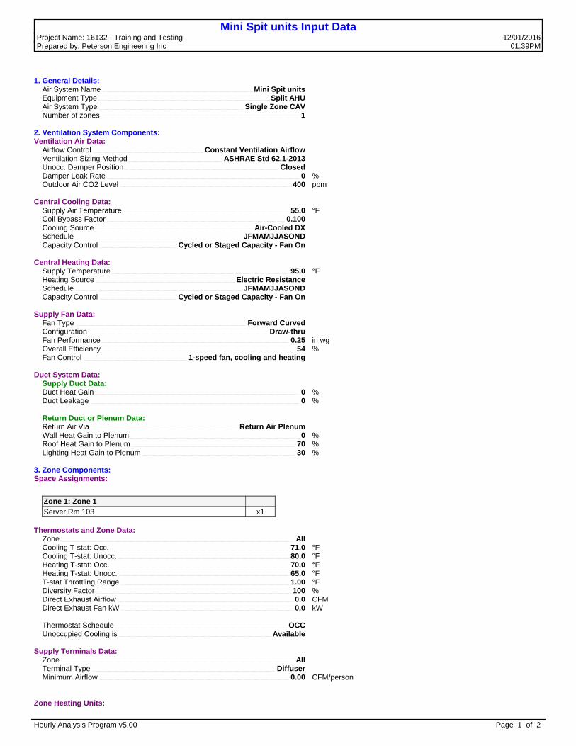
Mini Spit units Input DataProject Name: 16132 - Training and Testing 12/01/2016 Prepared by: Peterson Engineering Inc 01:40PM
1. General Details: Air System Name Mini Spit units Equipment Type Split AHU Air System Type Single Zone CAV Number of zones 1
2. Ventilation System Components:Ventilation Air Data: Airflow Control Constant Ventilation Airflow Ventilation Sizing Method ASHRAE Std 62.1-2013 Unocc. Damper Position Closed Damper Leak Rate 0 % Outdoor Air CO2 Level 400 ppm
Central Cooling Data: Supply Air Temperature 55.0 °F Coil Bypass Factor 0.100 Cooling Source Air-Cooled DX Schedule JFMAMJJASOND Capacity Control Cycled or Staged Capacity - Fan On
Central Heating Data: Supply Temperature 95.0 °F Heating Source Electric Resistance Schedule JFMAMJJASOND Capacity Control Cycled or Staged Capacity - Fan On
Supply Fan Data: Fan Type Forward Curved Configuration Draw-thru Fan Performance 0.25 in wg Overall Efficiency 54 % Fan Control 1-speed fan, cooling and heating
Duct System Data: Supply Duct Data: Duct Heat Gain 0 % Duct Leakage 0 %
Return Duct or Plenum Data: Return Air Via Return Air Plenum Wall Heat Gain to Plenum 0 % Roof Heat Gain to Plenum 70 % Lighting Heat Gain to Plenum 30 %
3. Zone Components:Space Assignments:
Zone 1: Zone 1 Server Rm 103 x1
Thermostats and Zone Data: Zone All Cooling T-stat: Occ. 71.0 °F Cooling T-stat: Unocc. 80.0 °F Heating T-stat: Occ. 70.0 °F Heating T-stat: Unocc. 65.0 °F T-stat Throttling Range 1.00 °F Diversity Factor 100 % Direct Exhaust Airflow 0.0 CFM Direct Exhaust Fan kW 0.0 kW
Thermostat Schedule OCC Unoccupied Cooling is Available
Supply Terminals Data: Zone All Terminal Type Diffuser Minimum Airflow 0.00 CFM/person
Zone Heating Units:
Hourly Analysis Program v5.00 Page 1 of 2

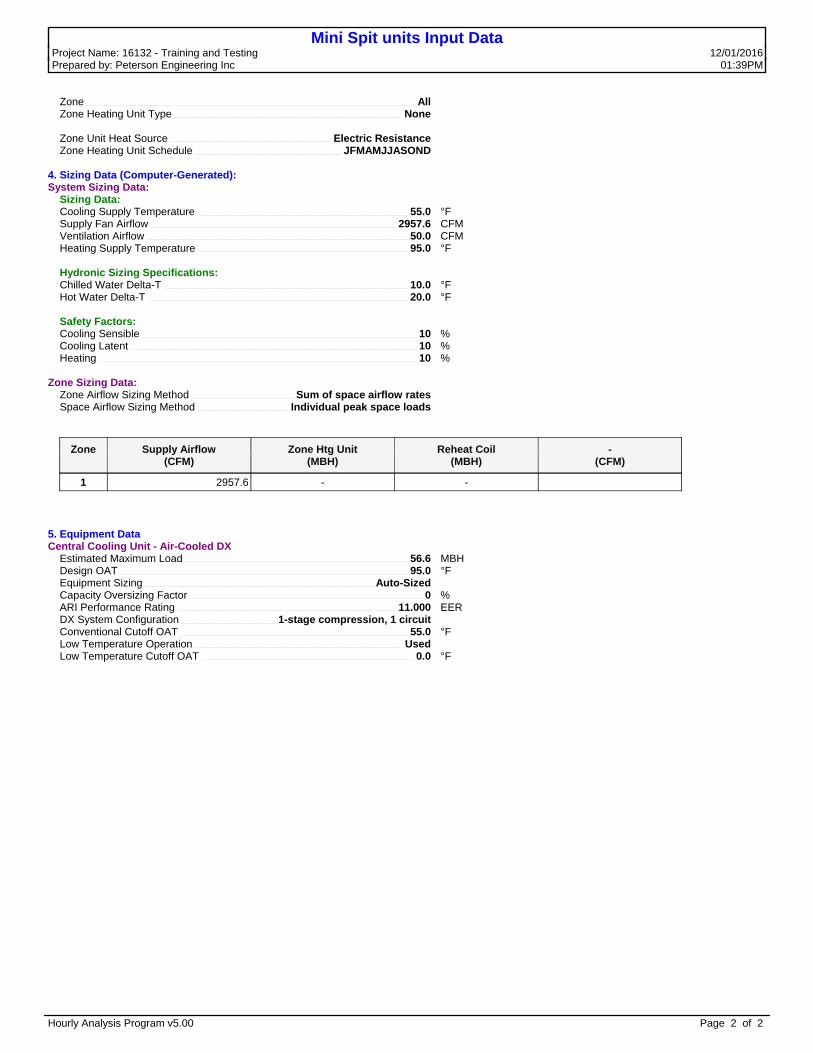
Mini Spit units Input DataProject Name: 16132 - Training and Testing 12/01/2016 Prepared by: Peterson Engineering Inc 01:40PM
Zone All Zone Heating Unit Type None
Zone Unit Heat Source Electric Resistance Zone Heating Unit Schedule JFMAMJJASOND
4. Sizing Data (Computer-Generated):System Sizing Data: Sizing Data: Cooling Supply Temperature 55.0 °F Supply Fan Airflow 2957.6 CFM Ventilation Airflow 50.0 CFM Heating Supply Temperature 95.0 °F
Hydronic Sizing Specifications: Chilled Water Delta-T 10.0 °F Hot Water Delta-T 20.0 °F
Safety Factors: Cooling Sensible 10 % Cooling Latent 10 % Heating 10 %
Zone Sizing Data: Zone Airflow Sizing Method Sum of space airflow rates Space Airflow Sizing Method Individual peak space loads
Zone Supply Airflow Zone Htg Unit Reheat Coil - (CFM) (MBH) (MBH) (CFM)
1 2957.6 - -
5. Equipment DataCentral Cooling Unit - Air-Cooled DX Estimated Maximum Load 56.6 MBH Design OAT 95.0 °F Equipment Sizing Auto-Sized Capacity Oversizing Factor 0 % ARI Performance Rating 11.000 EER DX System Configuration 1-stage compression, 1 circuit Conventional Cutoff OAT 55.0 °F Low Temperature Operation Used Low Temperature Cutoff OAT 0.0 °F
Hourly Analysis Program v5.00 Page 2 of 2
Mini Spit units Input DataProject Name: 16132 - Training and Testing 12/01/2016 Prepared by: Peterson Engineering Inc 01:39PM
1. General Details: Air System Name Mini Spit units Equipment Type Split AHU Air System Type Single Zone CAV Number of zones 1
2. Ventilation System Components:Ventilation Air Data: Airflow Control Constant Ventilation Airflow Ventilation Sizing Method ASHRAE Std 62.1-2013 Unocc. Damper Position Closed Damper Leak Rate 0 % Outdoor Air CO2 Level 400 ppm
Central Cooling Data: Supply Air Temperature 55.0 °F Coil Bypass Factor 0.100 Cooling Source Air-Cooled DX Schedule JFMAMJJASOND Capacity Control Cycled or Staged Capacity - Fan On
Central Heating Data: Supply Temperature 95.0 °F Heating Source Electric Resistance Schedule JFMAMJJASOND Capacity Control Cycled or Staged Capacity - Fan On
Supply Fan Data: Fan Type Forward Curved Configuration Draw-thru Fan Performance 0.25 in wg Overall Efficiency 54 % Fan Control 1-speed fan, cooling and heating
Duct System Data: Supply Duct Data: Duct Heat Gain 0 % Duct Leakage 0 %
Return Duct or Plenum Data: Return Air Via Return Air Plenum Wall Heat Gain to Plenum 0 % Roof Heat Gain to Plenum 70 % Lighting Heat Gain to Plenum 30 %
3. Zone Components:Space Assignments:
Zone 1: Zone 1 Server Rm 103 x1
Thermostats and Zone Data: Zone All Cooling T-stat: Occ. 71.0 °F Cooling T-stat: Unocc. 80.0 °F Heating T-stat: Occ. 70.0 °F Heating T-stat: Unocc. 65.0 °F T-stat Throttling Range 1.00 °F Diversity Factor 100 % Direct Exhaust Airflow 0.0 CFM Direct Exhaust Fan kW 0.0 kW
Thermostat Schedule OCC Unoccupied Cooling is Available
Supply Terminals Data: Zone All Terminal Type Diffuser Minimum Airflow 0.00 CFM/person
Zone Heating Units:
Hourly Analysis Program v5.00 Page 1 of 2
Mini Spit units Input DataProject Name: 16132 - Training and Testing 12/01/2016 Prepared by: Peterson Engineering Inc 01:39PM
Zone All Zone Heating Unit Type None
Zone Unit Heat Source Electric Resistance Zone Heating Unit Schedule JFMAMJJASOND
4. Sizing Data (Computer-Generated):System Sizing Data: Sizing Data: Cooling Supply Temperature 55.0 °F Supply Fan Airflow 2957.6 CFM Ventilation Airflow 50.0 CFM Heating Supply Temperature 95.0 °F
Hydronic Sizing Specifications: Chilled Water Delta-T 10.0 °F Hot Water Delta-T 20.0 °F
Safety Factors: Cooling Sensible 10 % Cooling Latent 10 % Heating 10 %
Zone Sizing Data: Zone Airflow Sizing Method Sum of space airflow rates Space Airflow Sizing Method Individual peak space loads
Zone Supply Airflow Zone Htg Unit Reheat Coil - (CFM) (MBH) (MBH) (CFM)
1 2957.6 - -
5. Equipment DataCentral Cooling Unit - Air-Cooled DX Estimated Maximum Load 56.6 MBH Design OAT 95.0 °F Equipment Sizing Auto-Sized Capacity Oversizing Factor 0 % ARI Performance Rating 11.000 EER DX System Configuration 1-stage compression, 1 circuit Conventional Cutoff OAT 55.0 °F Low Temperature Operation Used Low Temperature Cutoff OAT 0.0 °F
Hourly Analysis Program v5.00 Page 2 of 2

Design Weather Parameters & MSHGs16132 - Training and Testing 12/01/2016 Peterson Engineering Inc 06:13PM
Design Parameters:
City Name Hurlburt Field Location Florida Latitude 30.4 Deg. Longitude 87.3 Deg. Elevation 30.0 ft Summer Design Dry-Bulb 95.0 °F Summer Coincident Wet-Bulb 78.0 °F Summer Daily Range 15.3 °F Winter Design Dry-Bulb 25.0 °F Winter Design Wet-Bulb 23.6 °F Atmospheric Clearness Number 0.90 Average Ground Reflectance 0.20 Soil Conductivity 0.800 BTU/(hr·ft·°F) Local Time Zone (GMT +/- N hours) 6.0 hours Consider Daylight Savings Time No Simulation Weather Data N/A Current Data is User Modified Design Cooling Months January to December
Design Day Maximum Solar Heat Gains
(The MSHG values are expressed in BTU/(hr·ft²) )
Month N NNE NE ENE E ESE SE SSE SJanuary 21.7 21.7 27.0 98.9 164.1 202.9 227.7 225.2 217.2February 25.0 25.0 64.7 132.1 190.6 219.3 222.7 206.0 192.5March 28.6 29.9 106.4 164.7 201.9 217.5 199.6 169.0 150.2April 32.2 70.6 136.9 183.9 202.9 194.4 165.5 120.7 95.5May 35.4 99.0 154.8 190.5 197.8 175.3 136.2 83.3 59.9June 45.5 107.2 161.1 191.1 192.6 165.4 122.7 68.8 49.1July 36.5 97.3 154.4 187.2 192.1 172.1 132.3 80.3 57.9August 33.6 67.8 134.3 177.4 193.9 188.6 159.1 116.0 91.9September 29.8 30.1 98.6 158.0 192.1 206.5 193.8 165.4 147.8October 25.9 25.9 60.7 131.3 177.6 212.0 214.7 199.8 188.6November 22.1 22.1 29.5 94.4 159.9 204.7 221.7 219.6 215.8December 20.3 20.3 20.3 81.2 151.6 195.4 224.9 227.9 224.1Month SSW SW WSW W WNW NW NNW HOR MultJanuary 225.2 227.6 202.6 164.2 98.7 27.3 21.7 163.7 1.00February 205.4 221.7 220.3 189.7 129.2 65.6 25.0 199.5 1.00March 169.6 199.5 217.7 203.5 162.5 106.4 31.3 229.6 1.00April 119.8 163.2 197.1 202.1 179.6 137.8 72.1 245.7 1.00May 82.2 134.3 178.2 195.4 187.9 156.4 100.7 249.9 1.00June 67.6 121.8 168.2 189.0 189.7 162.1 110.0 248.6 1.00July 79.6 131.6 173.3 189.6 186.2 154.7 99.4 245.6 1.00August 115.2 157.0 189.9 195.0 173.8 134.1 71.7 240.2 1.00September 165.9 194.4 205.6 196.0 156.5 95.2 32.6 223.6 1.00October 200.2 215.6 210.9 180.4 131.8 58.6 25.9 197.5 1.00November 221.1 221.1 204.7 156.4 98.7 27.5 22.1 164.7 1.00December 228.1 223.2 199.1 145.0 85.8 20.3 20.3 149.4 1.00
Mult. = User-defined solar multiplier factor.
Hourly Analysis Program vv5.00 Page 1 of 1

Space Input Data16132 - Training and Testing 12/01/2016 Peterson Engineering Inc 01:41PM
Conference
1. General Details: Floor Area 250.0 ft² Avg. Ceiling Height 9.0 ft Building Weight 70.0 lb/ft²1.1. OA Ventilation Requirements: Space Usage GENERAL: Conference/meeting OA Requirement 1 5.0 CFM/person OA Requirement 2 0.06 CFM/ft² Space Usage Defaults ASHRAE Standard 62.1-2013
2. Internals:2.1. Overhead Lighting: Fixture Type Recessed (Unvented) Wattage 1.00 W/ft² Ballast Multiplier 1.00 Schedule Lights
2.4. People: Occupancy 12.0 People Activity Level Office Work Sensible 245.0 BTU/hr/person Latent 205.0 BTU/hr/person Schedule People
2.2. Task Lighting: Wattage 0.00 W/ft² Schedule None
2.5. Miscellaneous Loads: Sensible 0 BTU/hr Schedule None Latent 0 BTU/hr Schedule None
2.3. Electrical Equipment: Wattage 300.0 Watts Schedule Electrical
3. Walls, Windows, Doors:
Exp. Wall Gross Area (ft²) Window 1 Qty. Window 2 Qty. Door 1 Qty.
S 240.0 1 0 0W 130.0 0 0 0
3.1. Construction Types for Exposure S Wall Type Default Wall Assembly 1st Window Type 4' window
3.2. Construction Types for Exposure W Wall Type Default Wall Assembly
4. Roofs, Skylights:
Exp. Roof Gross Area (ft²) Roof Slope (deg.) Skylight Qty.
H 312.0 0 0
4.1. Construction Types for Exposure H Roof Type Default Roof Assembly
5. Infiltration: Design Cooling 0.20 CFM/ft² Design Heating 0.20 CFM/ft² Energy Analysis 0.20 CFM/ft² Infiltration occurs only when the fan is off.
6. Floors: Type Slab Floor On Grade Floor Area 250.0 ft² Total Floor U-Value 0.100 BTU/(hr·ft²·°F) Exposed Perimeter 0.0 ft Edge Insulation R-Value 0.00 (hr·ft²·°F)/BTU
7. Partitions: (No partition data).
Hourly Analysis Program vv5.00 Page 1 of 9

Space Input Data16132 - Training and Testing 12/01/2016 Peterson Engineering Inc 01:41PM
Entry 101
1. General Details: Floor Area 240.0 ft² Avg. Ceiling Height 9.0 ft Building Weight 70.0 lb/ft²1.1. OA Ventilation Requirements: Space Usage GENERAL: Corridor OA Requirement 1 0.0 CFM/person OA Requirement 2 0.06 CFM/ft² Space Usage Defaults ASHRAE Standard 62.1-2013
2. Internals:2.1. Overhead Lighting: Fixture Type Recessed (Unvented) Wattage 1.00 W/ft² Ballast Multiplier 1.00 Schedule Lights
2.4. People: Occupancy 0.0 Person Activity Level Office Work Sensible 245.0 BTU/hr/person Latent 205.0 BTU/hr/person Schedule None
2.2. Task Lighting: Wattage 0.00 W/ft² Schedule None
2.5. Miscellaneous Loads: Sensible 0 BTU/hr Schedule None Latent 0 BTU/hr Schedule None
2.3. Electrical Equipment: Wattage 740.0 Watts Schedule Electrical
3. Walls, Windows, Doors:
Exp. Wall Gross Area (ft²) Window 1 Qty. Window 2 Qty. Door 1 Qty.
W 106.0 0 0 1
3.1. Construction Types for Exposure W Wall Type Default Wall Assembly Door Type 3' Door
4. Roofs, Skylights:
Exp. Roof Gross Area (ft²) Roof Slope (deg.) Skylight Qty.
H 240.0 0 0
4.1. Construction Types for Exposure H Roof Type Default Roof Assembly
5. Infiltration: Design Cooling 0.20 CFM/ft² Design Heating 0.20 CFM/ft² Energy Analysis 0.20 CFM/ft² Infiltration occurs only when the fan is off.
6. Floors: Type Slab Floor On Grade Floor Area 240.0 ft² Total Floor U-Value 0.100 BTU/(hr·ft²·°F) Exposed Perimeter 0.0 ft Edge Insulation R-Value 0.00 (hr·ft²·°F)/BTU
7. Partitions: (No partition data).
Hourly Analysis Program vv5.00 Page 2 of 9

Space Input Data16132 - Training and Testing 12/01/2016 Peterson Engineering Inc 01:41PM
Mechanical 110
1. General Details: Floor Area 125.0 ft² Avg. Ceiling Height 9.0 ft Building Weight 70.0 lb/ft²1.1. OA Ventilation Requirements: Space Usage User-Defined OA Requirement 1 0.0 CFM/person OA Requirement 2 0.00 CFM/ft² Space Usage Defaults ASHRAE Standard 62.1-2013
2. Internals:2.1. Overhead Lighting: Fixture Type Recessed (Unvented) Wattage 2.00 W/ft² Ballast Multiplier 1.00 Schedule Lights
2.4. People: Occupancy 0.0 Person Activity Level Office Work Sensible 245.0 BTU/hr/person Latent 205.0 BTU/hr/person Schedule None
2.2. Task Lighting: Wattage 0.00 W/ft² Schedule None
2.5. Miscellaneous Loads: Sensible 0 BTU/hr Schedule None Latent 0 BTU/hr Schedule None
2.3. Electrical Equipment: Wattage 1000.0 Watts Schedule Electrical
3. Walls, Windows, Doors:
Exp. Wall Gross Area (ft²) Window 1 Qty. Window 2 Qty. Door 1 Qty.
E 180.0 0 0 1N 70.0 0 0 0
3.1. Construction Types for Exposure E Wall Type Default Wall Assembly Door Type 3' Door
3.2. Construction Types for Exposure N Wall Type Default Wall Assembly
4. Roofs, Skylights:
Exp. Roof Gross Area (ft²) Roof Slope (deg.) Skylight Qty.
H 125.0 0 0
4.1. Construction Types for Exposure H Roof Type Default Roof Assembly
5. Infiltration: Design Cooling 0.20 CFM/ft² Design Heating 0.20 CFM/ft² Energy Analysis 0.20 CFM/ft² Infiltration occurs only when the fan is off.
6. Floors: Type Slab Floor On Grade Floor Area 125.0 ft² Total Floor U-Value 0.100 BTU/(hr·ft²·°F) Exposed Perimeter 0.0 ft Edge Insulation R-Value 0.00 (hr·ft²·°F)/BTU
7. Partitions: (No partition data).
Hourly Analysis Program vv5.00 Page 3 of 9

Space Input Data16132 - Training and Testing 12/01/2016 Peterson Engineering Inc 01:41PM
Office 104
1. General Details: Floor Area 165.0 ft² Avg. Ceiling Height 9.0 ft Building Weight 70.0 lb/ft²1.1. OA Ventilation Requirements: Space Usage OFFICE: Office space OA Requirement 1 5.0 CFM/person OA Requirement 2 0.06 CFM/ft² Space Usage Defaults ASHRAE Standard 62.1-2013
2. Internals:2.1. Overhead Lighting: Fixture Type Recessed (Unvented) Wattage 1.50 W/ft² Ballast Multiplier 1.00 Schedule Lights
2.4. People: Occupancy 2.0 People Activity Level Office Work Sensible 245.0 BTU/hr/person Latent 205.0 BTU/hr/person Schedule People
2.2. Task Lighting: Wattage 60.0 Watts Schedule People
2.5. Miscellaneous Loads: Sensible 0 BTU/hr Schedule None Latent 0 BTU/hr Schedule None
2.3. Electrical Equipment: Wattage 700.0 Watts Schedule Electrical
3. Walls, Windows, Doors:
Exp. Wall Gross Area (ft²) Window 1 Qty. Window 2 Qty. Door 1 Qty.
E 150.0 1 0 0
3.1. Construction Types for Exposure E Wall Type Default Wall Assembly 1st Window Type 4' window
4. Roofs, Skylights:
Exp. Roof Gross Area (ft²) Roof Slope (deg.) Skylight Qty.
H 165.0 0 0
4.1. Construction Types for Exposure H Roof Type Default Roof Assembly
5. Infiltration: Design Cooling 0.20 CFM/ft² Design Heating 0.20 CFM/ft² Energy Analysis 0.00 CFM Infiltration occurs only when the fan is off.
6. Floors: Type Slab Floor On Grade Floor Area 165.0 ft² Total Floor U-Value 0.100 BTU/(hr·ft²·°F) Exposed Perimeter 0.0 ft Edge Insulation R-Value 0.00 (hr·ft²·°F)/BTU
7. Partitions: (No partition data).
Hourly Analysis Program vv5.00 Page 4 of 9

Space Input Data16132 - Training and Testing 12/01/2016 Peterson Engineering Inc 01:41PM
Office 105
1. General Details: Floor Area 100.0 ft² Avg. Ceiling Height 9.0 ft Building Weight 70.0 lb/ft²1.1. OA Ventilation Requirements: Space Usage OFFICE: Office space OA Requirement 1 5.0 CFM/person OA Requirement 2 0.06 CFM/ft² Space Usage Defaults ASHRAE Standard 62.1-2013
2. Internals:2.1. Overhead Lighting: Fixture Type Recessed (Unvented) Wattage 1.00 W/ft² Ballast Multiplier 1.00 Schedule Lights
2.4. People: Occupancy 1.0 Person Activity Level Office Work Sensible 245.0 BTU/hr/person Latent 205.0 BTU/hr/person Schedule People
2.2. Task Lighting: Wattage 30.0 Watts Schedule People
2.5. Miscellaneous Loads: Sensible 0 BTU/hr Schedule None Latent 0 BTU/hr Schedule None
2.3. Electrical Equipment: Wattage 350.0 Watts Schedule Electrical
3. Walls, Windows, Doors: (No Wall, Window, Door data).
4. Roofs, Skylights:
Exp. Roof Gross Area (ft²) Roof Slope (deg.) Skylight Qty.
H 100.0 0 0
4.1. Construction Types for Exposure H Roof Type Default Roof Assembly
5. Infiltration: Design Cooling 0.00 CFM Design Heating 0.00 CFM Energy Analysis 0.00 CFM Infiltration occurs only when the fan is off.
6. Floors: Type Slab Floor On Grade Floor Area 100.0 ft² Total Floor U-Value 0.100 BTU/(hr·ft²·°F) Exposed Perimeter 0.0 ft Edge Insulation R-Value 0.00 (hr·ft²·°F)/BTU
7. Partitions: (No partition data).
Hourly Analysis Program vv5.00 Page 5 of 9

Space Input Data16132 - Training and Testing 12/01/2016 Peterson Engineering Inc 01:41PM
Office 106
1. General Details: Floor Area 100.0 ft² Avg. Ceiling Height 9.0 ft Building Weight 70.0 lb/ft²1.1. OA Ventilation Requirements: Space Usage OFFICE: Office space OA Requirement 1 5.0 CFM/person OA Requirement 2 0.06 CFM/ft² Space Usage Defaults ASHRAE Standard 62.1-2013
2. Internals:2.1. Overhead Lighting: Fixture Type Recessed (Unvented) Wattage 1.00 W/ft² Ballast Multiplier 1.00 Schedule Lights
2.4. People: Occupancy 1.0 Person Activity Level Office Work Sensible 245.0 BTU/hr/person Latent 205.0 BTU/hr/person Schedule People
2.2. Task Lighting: Wattage 30.0 Watts Schedule People
2.5. Miscellaneous Loads: Sensible 0 BTU/hr Schedule None Latent 0 BTU/hr Schedule None
2.3. Electrical Equipment: Wattage 350.0 Watts Schedule Electrical
3. Walls, Windows, Doors: (No Wall, Window, Door data).
4. Roofs, Skylights:
Exp. Roof Gross Area (ft²) Roof Slope (deg.) Skylight Qty.
H 100.0 0 0
4.1. Construction Types for Exposure H Roof Type Default Roof Assembly
5. Infiltration: Design Cooling 0.00 CFM Design Heating 0.00 CFM Energy Analysis 0.00 CFM Infiltration occurs only when the fan is off.
6. Floors: Type Slab Floor On Grade Floor Area 100.0 ft² Total Floor U-Value 0.100 BTU/(hr·ft²·°F) Exposed Perimeter 0.0 ft Edge Insulation R-Value 0.00 (hr·ft²·°F)/BTU
7. Partitions: (No partition data).
Hourly Analysis Program vv5.00 Page 6 of 9

Space Input Data16132 - Training and Testing 12/01/2016 Peterson Engineering Inc 01:41PM
Server Rm 103
1. General Details: Floor Area 250.0 ft² Avg. Ceiling Height 9.0 ft Building Weight 70.0 lb/ft²1.1. OA Ventilation Requirements: Space Usage OFFICE: Telephone/data entry OA Requirement 1 5.0 CFM/person OA Requirement 2 0.06 CFM/ft² Space Usage Defaults ASHRAE Standard 62.1-2013
2. Internals:2.1. Overhead Lighting: Fixture Type Recessed (Unvented) Wattage 360.0 Watts Ballast Multiplier 1.00 Schedule Lights
2.4. People: Occupancy 5.0 People Activity Level Office Work Sensible 245.0 BTU/hr/person Latent 205.0 BTU/hr/person Schedule People
2.2. Task Lighting: Wattage 0.00 W/ft² Schedule None
2.5. Miscellaneous Loads: Sensible 35000 BTU/hr Schedule Electrical Latent 0 BTU/hr Schedule None
2.3. Electrical Equipment: Wattage 2500.0 Watts Schedule Electrical
3. Walls, Windows, Doors:
Exp. Wall Gross Area (ft²) Window 1 Qty. Window 2 Qty. Door 1 Qty.
S 220.0 0 0 0E 115.0 0 0 1
3.1. Construction Types for Exposure S Wall Type Default Wall Assembly
3.2. Construction Types for Exposure E Wall Type Default Wall Assembly Door Type 3' Door
4. Roofs, Skylights:
Exp. Roof Gross Area (ft²) Roof Slope (deg.) Skylight Qty.
H 250.0 0 0
4.1. Construction Types for Exposure H Roof Type Default Roof Assembly
5. Infiltration: Design Cooling 0.20 CFM/ft² Design Heating 0.20 CFM/ft² Energy Analysis 0.20 CFM/ft² Infiltration occurs only when the fan is off.
6. Floors: Type Slab Floor On Grade Floor Area 250.0 ft² Total Floor U-Value 0.100 BTU/(hr·ft²·°F) Exposed Perimeter 0.0 ft Edge Insulation R-Value 0.00 (hr·ft²·°F)/BTU
7. Partitions: (No partition data).
Hourly Analysis Program vv5.00 Page 7 of 9

Space Input Data16132 - Training and Testing 12/01/2016 Peterson Engineering Inc 01:41PM
Training Rm 109
1. General Details: Floor Area 835.0 ft² Avg. Ceiling Height 9.0 ft Building Weight 70.0 lb/ft²1.1. OA Ventilation Requirements: Space Usage GENERAL: Conference/meeting OA Requirement 1 5.0 CFM/person OA Requirement 2 0.06 CFM/ft² Space Usage Defaults ASHRAE Standard 62.1-2013
2. Internals:2.1. Overhead Lighting: Fixture Type Recessed (Unvented) Wattage 1.00 W/ft² Ballast Multiplier 1.00 Schedule Lights
2.4. People: Occupancy 20.0 People Activity Level Office Work Sensible 245.0 BTU/hr/person Latent 205.0 BTU/hr/person Schedule People
2.2. Task Lighting: Wattage 0.00 W/ft² Schedule None
2.5. Miscellaneous Loads: Sensible 0 BTU/hr Schedule None Latent 0 BTU/hr Schedule None
2.3. Electrical Equipment: Wattage 1060.0 Watts Schedule Electrical
3. Walls, Windows, Doors:
Exp. Wall Gross Area (ft²) Window 1 Qty. Window 2 Qty. Door 1 Qty.
N 370.0 0 0 0E 226.0 0 0 1
3.1. Construction Types for Exposure N Wall Type Default Wall Assembly
3.2. Construction Types for Exposure E Wall Type Default Wall Assembly Door Type 3' Door
4. Roofs, Skylights:
Exp. Roof Gross Area (ft²) Roof Slope (deg.) Skylight Qty.
H 880.0 0 0
4.1. Construction Types for Exposure H Roof Type Default Roof Assembly
5. Infiltration: Design Cooling 0.20 CFM/ft² Design Heating 0.20 CFM/ft² Energy Analysis 0.20 CFM/ft² Infiltration occurs only when the fan is off.
6. Floors: Type Slab Floor On Grade Floor Area 835.0 ft² Total Floor U-Value 0.100 BTU/(hr·ft²·°F) Exposed Perimeter 0.0 ft Edge Insulation R-Value 0.00 (hr·ft²·°F)/BTU
7. Partitions: (No partition data).
Hourly Analysis Program vv5.00 Page 8 of 9

Space Input Data16132 - Training and Testing 12/01/2016 Peterson Engineering Inc 01:41PM
Unisex Tlt
1. General Details: Floor Area 60.0 ft² Avg. Ceiling Height 9.0 ft Building Weight 70.0 lb/ft²1.1. OA Ventilation Requirements: Space Usage User-Defined OA Requirement 1 0.0 CFM/person OA Requirement 2 0.00 CFM/ft² Space Usage Defaults ASHRAE Standard 62.1-2013
2. Internals:2.1. Overhead Lighting: Fixture Type Recessed (Unvented) Wattage 1.00 W/ft² Ballast Multiplier 1.00 Schedule Lights
2.4. People: Occupancy 1.0 Person Activity Level Seated at Rest Sensible 230.0 BTU/hr/person Latent 120.0 BTU/hr/person Schedule People
2.2. Task Lighting: Wattage 0.00 W/ft² Schedule None
2.5. Miscellaneous Loads: Sensible 0 BTU/hr Schedule None Latent 0 BTU/hr Schedule None
2.3. Electrical Equipment: Wattage 0.00 W/ft² Schedule None
3. Walls, Windows, Doors:
Exp. Wall Gross Area (ft²) Window 1 Qty. Window 2 Qty. Door 1 Qty.
E 85.0 0 0 0
3.1. Construction Types for Exposure E Wall Type Default Wall Assembly
4. Roofs, Skylights:
Exp. Roof Gross Area (ft²) Roof Slope (deg.) Skylight Qty.
H 60.0 0 0
4.1. Construction Types for Exposure H Roof Type Default Roof Assembly
5. Infiltration: Design Cooling 0.20 CFM/ft² Design Heating 0.20 CFM/ft² Energy Analysis 0.20 CFM/ft² Infiltration occurs only when the fan is off.
6. Floors: Type Slab Floor On Grade Floor Area 60.0 ft² Total Floor U-Value 0.100 BTU/(hr·ft²·°F) Exposed Perimeter 0.0 ft Edge Insulation R-Value 0.00 (hr·ft²·°F)/BTU
7. Partitions: (No partition data).
Hourly Analysis Program vv5.00 Page 9 of 9

Wall Constructions16132 - Training and Testing 12/01/2016 Peterson Engineering Inc 01:41PM
Default Wall Assembly
Wall Details Outside Surface Color Medium Absorptivity 0.675 Overall U-Value 0.044 BTU/(hr·ft²·°F)
Wall Layers Details (Inside to Outside) Thickness Density Specific Ht. R-Value WeightLayers in lb/ft³ BTU / (lb·°F) (hr·ft²·°F)/BTU lb/ft²
Inside surface resistance 0.000 0.0 0.00 0.68500 0.05/8-in gypsum board 0.625 50.0 0.26 0.56004 2.6R-19 batt insulation 6.000 0.5 0.20 19.23077 0.31/2-in gypsum board 0.500 50.0 0.26 0.44803 2.1Air space 2.000 0.0 0.00 0.91000 0.0Face brick 4.000 125.0 0.22 0.43286 41.7Outside surface resistance 0.000 0.0 0.00 0.33300 0.0
Totals 13.125 - 22.59969 46.6
Hourly Analysis Program vv5.00 Page 1 of 1

Door Constructions16132 - Training and Testing 12/01/2016 Peterson Engineering Inc 06:12PM
3' Door
Door Details: Gross Area 18.0 ft² Door U-Value 0.650 BTU/(hr·ft²·°F)
Glass Details: Glass Area 0.0 ft² Glass U-Value 0.580 BTU/(hr·ft²·°F) Glass Shade Coefficient 0.880 Glass Shaded All Day? No
Hourly Analysis Program vv5.00 Page 1 of 1

Roof Constructions16132 - Training and Testing 12/01/2016 Peterson Engineering Inc 06:13PM
Default Roof Assembly
Roof Details Outside Surface Color Medium Absorptivity 0.675 Overall U-Value 0.030 BTU/(hr·ft²·°F)
Roof Layers Details (Inside to Outside) Thickness Density Specific Ht. R-Value WeightLayers in lb/ft³ BTU / (lb·°F) (hr·ft²·°F)/BTU lb/ft²
Inside surface resistance 0.000 0.0 0.00 0.68500 0.0Acoustical tile 0.250 21.0 0.19 0.67500 0.4Air space 0.000 0.0 0.00 0.91000 0.0R-30 batt insulation 9.500 0.5 0.20 30.44872 0.4Seam Metal Roof 0.034 489.0 0.12 0.00011 1.4Outside surface resistance 0.000 0.0 0.00 0.33300 0.0
Totals 9.784 - 33.05183 2.2
Hourly Analysis Program vv5.00 Page 1 of 1

PLUMBING DESIGN ANALYSIS

CONSTRUCT TRAINING FACILITY, 2 CSWW, BLDG. 91038 FTFA 16-1041 HURLBURT, FLORIDA
PLUMBING DESIGN ANALYSIS 1
PLUMBING DESIGN ANALYSIS FINAL SUBMITTAL
DESIGN CRITERIA:
• ASHRAE 90.1-2010, (I-P Edition) -- Energy Standard for Buildings Except Low-Rise
Residential Buildings • UFC 1-200-01- General Building Requirements • UFC 3-400-01, Energy Conservation • UFC 3-420-01, Plumbing Systems • UFC 3-420-01FA- Design: Plumbing Systems • National Electric Code • ASHRAE Handbooks- Latest Edition • ASTM B 32, Solder Metal • ASTM Standards – American Society of Testing and Materials • EPACT 05 Energy Policy Act 2005 • IBC - International Building Code • IMC- International Mechanical Code • IPC- International Plumbing Code • MSS SP 69 – Manufacturers Standardization Society of the Valve and Fittings Industry Inc. –
Pipe Hangers and Supports – Selection and Application • Uniform Federal Accessibility Standards, FED-STD-795 DESCRIPTION: All plumbing fixtures shall be water conservative type with manual faucets, flush valves and controls. Restroom and mechanical room shall have a floor drain. All floor drain p-traps shall be kept primed with the use of an approved trap primer device. Restroom shall be equipped with handicap accessible fixtures. Water pipe and fittings shall be Type “K” soft (below slab) and Type “L” hard copper tubing (above slab). Water supply piping shall be installed above ceilings. Fittings shall be copper. Valves shall be full port design ball valves. Drain, waste & vent pipe and fittings shall be PVC-DWV. Water and sanitary sewer piping shall terminate 5’ outside of building.

FIRE PROTECTION DESIGN ANALYSIS

CONSTRUCT TRAINING FACILITY, 2 CSWW, BLDG. 91038 FTFA 16-1041 HURLBURT, FLORIDA
FIRE PROTECTION DESIGN ANALYSIS 1
FIRE PROTECTION DESIGN ANALYSIS FINAL SUBMITTAL
DESIGN CRITERIA:
• UFC 3-600-01, Fire Protection Engineering for Facilities, 8 Aug 2016 • NFPA 13, Standard for the Installation of Sprinkler Systems • NFPA 13R, Standard for the Installation of Sprinkler Systems in Low-Rise Residential
Occupancies • NFPA 291, Recommended Practice for Fire Flow Testing and Marking of Hydrants • NFPA 20, Standard for the Installation of Stationary Pumps for Fire Protection • UL, Underwriters Laboratories
SPRINKLER SYSTEM DESCRIPTION 1. A new Training and Testing Facility is to be constructed. The new facility will require a wet
pipe fire suppression system to be installed. 2. A new 6” main will be tapped off the base water main and routed underground to provide
water for the new wet pipe fire sprinkler system in the new Training Facility. The riser will be sized to serve the new facility and located inside the mechanical room.
3. The new system shall be provided with a wet pipe riser including a backflow preventer, alarm check valve, flow switch, FDC and BFP forward flow test assembly. The new system shall also include piping and heads to sprinkle the building and protect the Architectural layout of the facility.
4. Piping 2” in diameter and smaller shall be threaded. Piping larger than 2” shall be welded, flanged, threaded, or groove connections. Piping shall be schedule 40 black steel.
5. The new wet pipe sprinkler system shall be designed and installed per ufc-3-600-01, 8Aug16; NFPA 13; the specifications; and the approval of the Authority Having Jurisdiction (AHJ).
HAZARD CLASSIFICATION 1. Hazard Classification: Light Hazard:
a. System Training 109 b. Unisex toilet 108 c. Offices 104-106 d. Entry 101 e. Corridor 107 f. Conference 102 g. Server room 103
2. Hazard Classification: Ordinary Hazard:
a. Mechanical 110

CONSTRUCT TRAINING FACILITY, 2 CSWW, BLDG. 91038 FTFA 16-1041 HURLBURT, FLORIDA
FIRE PROTECTION DESIGN ANALYSIS
PRELIMINARY HYDRAULIC CALCULATIONS


CONSTRUCT TRAINING FACILITY, 2 CSWW, BLDG. 91038 FTFA 16-1041 HURLBURT, FLORIDA
FIRE PROTECTION DESIGN ANALYSIS
FLOW TEST REPORT

WATER FLOW TEST REPORT
HYDRANT # & LOCATION:Flow - N. of Bldg 91024 / Read - SE of Bldg 91059 DATE: 1/31/2017
TEST BY: LWFP / Hurlburt Insp. Day or Week: Tuesday TIME OF DAY: 10:00 MIN. OF FLOW: 1
WATER SUPPLIED BY: Hurlburt Field
PURPOSE OF TEST: Design of Construct Training Facility 2CWSSDATA
FLOW HYDRANT(S) A1 A2 A3SIZE OPENING: 2.5 2.5
COEFFICIENT: 0.9 0.9
PITOT READING: 9.975 9.975
GPM: 530 530 0
TOTAL FLOW DURING TEST: 1060 GPM
STATIC READING: 65 PSI RESIDUAL: 35 PSI
RESULTS: AT 20 PSI RESIDUAL 1319 GPM AT 0 PSI 1609 GPM
ESTIMATED CONSUMPTION: 1060 GAL.REMARKS:
0 65
1060 35
1609 0
C = 0.9
D = 2.5
P = 9.975
0
1060
1319
16090
10
20
30
40
50
60
70
80
90
100
0 500 1000 1500 2000 2500
Pre
ssu
re,p
sig
Flow, gpm
Provided by:Living Water Fire Protection, LLC.
1160 McKenzie Rd.Cantonment, Fl. 32533
(850) 937-1850

WATER FLOW TEST REPORT
Provided by:Living Water Fire Protection, LLC.
1160 McKenzie Rd.Cantonment, Fl. 32533
(850) 937-1850

ELECTRICAL/TELECOMMUNICATIONS DESIGN ANALYSIS

Design/Build FTEV 16-1066 Construct Training Facility, 2 CWSS Hurlburt Field, Florida
ELECTRICAL DESIGN ANALYSIS 1
ELECTRICAL DESIGN ANALYSIS
FINAL SUBMITTAL CODES AND STANDARDS UFC 1-200-01 Design: General Building Requirements UFC 3-501-01 Electrical Engineering UFC 3-520-01 Interior Electrical Systems UFC 3-530-01 Design: Interior and Exterior Lighting and Controls UFC 3-580-01 Telecommunications Interior Infrastructure Planning and Design,
with Change 1, 1 June 2016 UFC 3-600-01 Fire Protection Engineering for Facilities UFC 4-010-01 Design: DoD Minimum Antiterrorism Standards for Buildings UFC 4-021-01 Mass Notification Systems ANSI C2 National Electrical Safety Code NFPA 70 National Electrical Code NFPA 780 Lightning Protection Systems IES Illuminating Engineering Society Lighting Handbook UL 96A Installation Requirements for Lightning Protection Systems Electrical Systems: The existing pad mounted transformer shall remain and shall be reused. A new service entrance panelboard shall be installed. The existing panel T shall remain and be connected to the new service entrance panel in the new building. Demolition Work: The existing electrical vaults at the site are to be removed. The existing panel T shall remain, the existing feeder shall be removed back to source. Secondary Distribution System: The main panel MP shall be a 400 amp service entrance main breaker. The voltage will be 208Y/120 volts, 3 phase, 4 wire. The underground service lateral to the facility shall run from the existing pad mounted transformer to Panel MP. Provide one spare empty conduit in the concrete service lateral run. Provide transient voltage surge suppression at new panelboards. Wiring shall be copper conductors in conduit. New panelboards shall have 25% spare capacity and 25% available physical space. Interior Lighting System: The lighting design shall incorporate the latest techniques of energy savings applied to lighting systems to include occupancy sensors. Interior lighting shall in general be LED. Illumination shall be provided in accordance with the UFC and IES recommendations.

Design/Build FTEV 16-1066 Construct Training Facility, 2 CWSS Hurlburt Field, Florida
ELECTRICAL DESIGN ANALYSIS 2
Emergency and Egress Lighting: Emergency lighting will be provided via LED emergency drivers. Exit lights will be LED type with battery backup. Emergency lights shall be installed in all areas. Emergency ballasts and emergency units shall be equipped with self-test diagnostics. Lightning Protection System: A complete new lightning protection system shall be installed to include but not limited to air terminals, main roof conductors, down conductors, and ground rods. The lightning protection system shall be certified by a third party inspection. The lighting protection system shall have master certification. Fire alarm/Mass Notification System: A complete new fire alarm and mass notification system shall be installed. The system shall consist of but not be limited to pull stations, smoke detectors, heat detectors, and signaling devices. A new fire alarm control panel and mass notification panel shall be installed. A new ultra-sensitive smoke detection system shall be installed to monitor below raised floor smoke detectors, the ultra-sensitive smoke detection system shall be capable of interfacing with the hvac controls. Communications: A 12 strand single mode fiber connection will be provided from the new facility to building 91023. A 25 pair copper cable will be provided in the new facility to the nearest usable splice as designated by 1 SOCS. All systems will be provided per the RFP and UFC requirements, and Hurlburt AFB communications standards.
All communications work area outlets will be served via a minimum 1” conduit from work area outlet to wall mount comm cabinet. All new cabling shall be category 6 plenum rated. Grounding system for basement level telecommunications rooms shall be connected to the existing earth electrode system. Voice/Data jacks shall be installed in locations required by the user as a minimum with additional jacks per the schematic design drawings. The devices shall be served from a new communications rack inside the new communications room. The horizontal wiring will not exceed the recommended length of 295’ (ft.), and all terminations of cabling will be made using the T568A standard. All cabling shall be installed continuous from the outlet to the communications rack. Patch panels, faceplates, and terminations will be per Hurlburt Field communication specifications. Label all equipment and cabling per the TIA/EIA-606B standard. Public Address System: A new PA system shall be installed consisting of zone controller, amplifier, cabling, conduit, backboxes, and power. System shall tie-in to existing PA system in Building 91024.

MEETING MINUTES

HEFFERNAN HOLLAND MORGAN
A R C H I T E C T U R E
3 12 S O U TH AL C AN I Z S T P E N S AC O L A, F L 3 250 2 85 0 433 2 79 9 AAC 0 0 1 94 2 H H M A. C O M
January 23, 2017
FA4417-16-R-0025, DESIGN/BUILD 2 CWSS TESTING AND TRAINING FACILITY
Date of Meeting: January 23, 2017
Final Fast Track/100% Unreviewed Design Review Meeting - Meeting Minutes
ATTENDEES: See attached attendance roster.
The purpose of this meeting was to review/discuss the Government review comments for the Final Fast
Track Civil/Structural Design Submittal, and 100% Unreviewed Design Submittal.
1. Jeff Fuller passed a sign-in sheet around and will email a copy along with meeting minute
distribution.
2. Paul Kendrick conducted the meeting. General Comments:
1. Paul Kendrick stated that the electronic PDF file of the Submittal had the contents of the Design Analysis out of order.
2. Regarding the environmental comment pertaining to tree removal, Josh Owens and Charlie Krasnosky stated that there is no intent to remove any trees.
Civil/Structural/Architectural Comments (Paul Kendrick):
3. Paul Kendrick requested the Design Team to revisit the sewer connection
to reduce the number of road crossings.
4. There were no issues regarding the structural comments.
5. Jeff Fuller expressed his concern regarding use of the XO-10 lock for the
existing gate to be relocated to between the existing and new buildings.
Josh Owens stated that these locks are very expensive, and the gate
would have to be completely re-worked to accommodate the proposed
hardware. SMSgt Rogers stated that the gate does not have to be
accessible from the street side, so only a means of egress hardware (exit
device) is required on the gate. The consensus was that the XO-10 lock is
not required, only an exit device.
6. Fire Chief Vazquez requested the Design Team to check the codes
regarding having electric-powered equipment (printers) in the egress
corridor. Discussion ensued regarding possible locations for the printers.

SMSgt Rogers stated that location of the printer in the entry allows for
printer use without disruptions to activities in the Training Room and the
Conference Room. If the printers cannot be located in the entry, small
desk-top printers can be put in the Training Room and Conference Room.
(Subsequent to the meeting, the Design Team investigated the codes
and could not find any language that would prohibit placement of a
printer in the means of egress, as long as it does not impede/obstruct
access to the exit. The floor plan was subsequently revised to align the
entry door with the corridor, and the printer located against the outside
wall between the entry door and restroom. This plan was reviewed and
approved by Paul Kendrick and the Fire Chief).
7. Jeff Fuller requested SMSgt Rogers provide clarification of the
type/size/function of the casework to be installed in the Training Room.
SMSgt stated that he would get that information.
8. David Bagwell requested SMSgt Rogers provide information regarding
electrical requirements of equipment for the Equipment Room. SMSgt
Rogers stated that he would provide that information.
9. David Bagwell advised SMSgt Rogers that any conduits/cables installed
below the access floor system in the Equipment Room must be in conduit
or plenum-rated, even though the area below the access floor is not being
used as a plenum.
10. Steve Loken advised David Bagwell that he was in process of completing
his electrical comments and would submit them shortly.
There being no further items of discussion, the meeting was adjourned.
Minutes compiled by Jeff Fuller. If there are corrections or additions, please contact Jeff Fuller at (850)
433-2799 or e-mail [email protected].


HEFFERNAN HOLLAND MORGAN
A R C H I T E C T U R E
3 12 S O U TH AL C AN I Z S T P E N S AC O L A, F L 3 250 2 85 0 433 2 79 9 AAC 0 0 1 94 2 H H M A. C O M
December 20, 2016
FA4417-16-R-0025, DESIGN/BUILD 2 CWSS TESTING AND TRAINING FACILITY
Date of Meeting: December 20, 2016
50% Design Review Meeting - Meeting Minutes
ATTENDEES: See attached attendance roster.
The purpose of this meeting was to review/discuss the Government review comments for the 50%
Design Submittal.
1. Jeff Fuller passed a sign-in sheet around and will email a copy along with meeting minute
distribution.
2. Josh Owens requested that Jeff Fuller begin by discussing the Architectural comments.
Architectural Comments (Paul Kendrick):
3. Review Comment #20. Double dashed lines on floor plan Sheet A1 indicate slab control joints.
These will be deleted from the architectural plan per request from Paul Kendrick.
4. Review Comment #22, regarding the casework, the user is to provide their needs (equip size,
power requirements, etc), so that the casework can be designed around those parameters. User
indicated that the casework will most likely be used to store IT equipment. Due to potential heat
load, the cabinet may require louvers.
5. Review Comment #29 regarding providing fascia extension and metal panels at gable ends
versus the gable ends being split-face CMU, Contractor will discuss the possibility with the PEMB
provider and determine if there is a cost impact.
6. Review Comment #36. The RFP Section 01 10 10 Page 14, para. 8.4.1.1. calls for exterior studs to be a minimum of 18GA. RFP Wall Section Drawings indicates exterior studs to be 16GA. Hurlburt Specification Section 05 40 00 Page 3, para. 2.03 B. provides for 8” 18GA studs (loadbearing) and 6” 16GA studs (loadbearing). Contractor will review cost issues between 16GA and 18GA studs.
7. Review Comment #44. Jeff Fuller will go by the existing building and determine the type of door hardware currently in use (mortise versus cylindrical). (Subsequent visit to site determined that the existing hardware is cylindrical).
8. Review Comment #45, interior doors 03 and 04 shall swing 180 degrees to accommodate moving equipment in and out of Equipment Room.
9. Review Comment #46, Jeff Fuller will go by the existing building to verify type of signage, and include it in the next submittal.
10. Review Comment #47 regarding providing exterior lighting, Contractor will consult with
Electrical Sub-contractor for pricing.
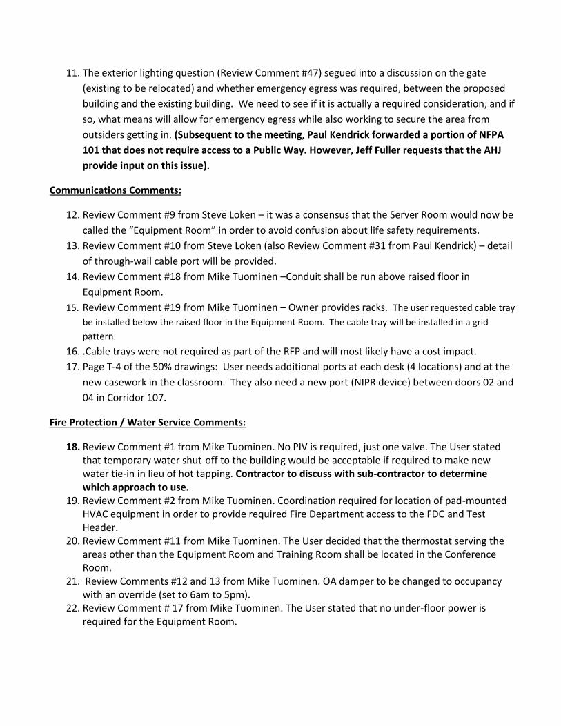
11. The exterior lighting question (Review Comment #47) segued into a discussion on the gate
(existing to be relocated) and whether emergency egress was required, between the proposed
building and the existing building. We need to see if it is actually a required consideration, and if
so, what means will allow for emergency egress while also working to secure the area from
outsiders getting in. (Subsequent to the meeting, Paul Kendrick forwarded a portion of NFPA
101 that does not require access to a Public Way. However, Jeff Fuller requests that the AHJ
provide input on this issue).
Communications Comments:
12. Review Comment #9 from Steve Loken – it was a consensus that the Server Room would now be
called the “Equipment Room” in order to avoid confusion about life safety requirements.
13. Review Comment #10 from Steve Loken (also Review Comment #31 from Paul Kendrick) – detail
of through-wall cable port will be provided.
14. Review Comment #18 from Mike Tuominen –Conduit shall be run above raised floor in
Equipment Room.
15. Review Comment #19 from Mike Tuominen – Owner provides racks. The user requested cable tray
be installed below the raised floor in the Equipment Room. The cable tray will be installed in a grid
pattern.
16. .Cable trays were not required as part of the RFP and will most likely have a cost impact.
17. Page T-4 of the 50% drawings: User needs additional ports at each desk (4 locations) and at the
new casework in the classroom. They also need a new port (NIPR device) between doors 02 and
04 in Corridor 107.
Fire Protection / Water Service Comments:
18. Review Comment #1 from Mike Tuominen. No PIV is required, just one valve. The User stated that temporary water shut-off to the building would be acceptable if required to make new water tie-in in lieu of hot tapping. Contractor to discuss with sub-contractor to determine which approach to use.
19. Review Comment #2 from Mike Tuominen. Coordination required for location of pad-mounted HVAC equipment in order to provide required Fire Department access to the FDC and Test Header.
20. Review Comment #11 from Mike Tuominen. The User decided that the thermostat serving the areas other than the Equipment Room and Training Room shall be located in the Conference Room.
21. Review Comments #12 and 13 from Mike Tuominen. OA damper to be changed to occupancy with an override (set to 6am to 5pm).
22. Review Comment # 17 from Mike Tuominen. The User stated that no under-floor power is required for the Equipment Room.

Electrical Comments (From Steve Loken):
23. David Bagwell needs User to provide power requirements and placement of User-provided racks
and equip in Equip Room. The user will provide a sketch with a layout of the Server Room to
show where receptacle devices should be located and their associated amperage
requirements. A list of equipment (and heat loads if possible) will be included as well.
24. The two new 4” conduits shown on Sheet E-4 should show going to the Server Room and not the
Thru Wall Cable Access port.
25. Review Comment #5, David Bagwell stated that a regular smoke detector for the under-floor area in Equipment Room is the only type required.
26. Review Comment #8, the User stated that an EPO switch is not required. HVAC shut-down switch is still required.
27. David Bagwell stated that All NIPR cables will terminate to patch panel.
28. The user requested 5 additional locations in System Training 109 for a box and 1” conduit stub
up above ceiling. This is for future cabling by the Gov’t. Also a 4” sleeve was requested from
above ceiling to into their rack/furniture.
29. David Bagwell stated that the LOC will be located in the Entry.
Structural Comments (From Paul Kendrick):
30. David Bagwell sat in for Jeff McCarthy to review structural comments. 31. Review Comment #13. Paul Kendrick stated that if wire mesh is used (as proposed by Jeff
McCarthy), that the mesh be flat sheets in lieu of rolled mesh. 32. Review Comment #14 regarding Charge II Standoff distance. Paul Kendrick will get with the ATO
and confirm if the 200’ distance to the bollards is correct.
Civil Comments:
33. Verify grades on new sidewalk between new and existing building for adequate drainage. 34. Gate types/swing direction need to be verified after determination regarding site egress issue.
Minutes compiled by Jeff Fuller. If there are corrections or additions, please contact Jeff Fuller at (850)
433-2799 or e-mail [email protected].


HEFFERNAN HOLLAND MORGAN
A R C H I T E C T U R E
3 1 2 S O U T H A L C AN I Z S T P E N S AC O L A , F L 3 2 5 0 2 8 5 0 4 3 3 2 7 9 9 A AC 00 1 9 4 2 H H M A . C O M
October 13, 2016
FA4417-16-R-0025, DESIGN/BUILD 2 CWSS TESTING AND TRAINING FACILITY
Date of Meeting: October 12, 2016
Post Award Kickoff (PAK) - Meeting Minutes
ATTENDEES: See attached attendance roster.
Mr. Paul Kendrick convened the meeting and introductions were made. Mr. Kendrick stated the
purpose for the meeting was to confirm that the programmed RFP materials are still meeting the facility
user’s needs. The consensus opinion was that the RFP is still valid. The following items were discussed:
1. Amy Tharp indicated there were stormwater permit concerns with an existing swale exemption for this project area. There is one small washout on the site. There will be no fee, but a FL 62330 permit will be required. Leona Lewis is handling this project for the state of Florida.
2. Bill Mozina indicated that a small Hubbel cabinet would be sufficient for comm head-end. 3. Bill Mozina requested a dual-jack be provided behind the TV/monitor in the Training Room. 4. The facility customers confirmed the following:
a. there are no SIPR requirements b. each of the 16 training seats needs a NIPR drop c. each office and the Training Room needs its own printer d. one telephone per row in the Training Room is required
5. David Bagwell requested the power requirements for the Server Room. 6. The accordion partition between the Server and Conference rooms is no longer desired. The
design-builder should replace it with a metal stud/gypsum board wall, including a half-glass personnel door.
7. Josh Rodgers requested a final list of equipment be provided for the Server Room. 8. Felipe Vazquez from Base Fire Department brought up concerns about the requirements for fire
detection and suppression in the “Server Room”. Please verify that per discussion, a VESDA system or clean agent fire suppression system will not be required in this area. The facility users indicated that based on the minimal amount of equipment proposed, “Server Room” might not be an appropriate name for this room.
9. Base Comm will research the existing outside plant cabling pathway between the new facility and Building 90123 and will let the A/E team know if there is an existing route that may be used.
10. At this time, there were no further issues to discuss and the group adjourned to the project site.
If there are corrections or additions, please contact Philip Morgan at (850) 433-2799 or e-mail


RESPONSE TO COMMENTS

1 Special Operations Civil Engineer Squadron Hurlburt Field, Florida Design Phase:
50%/UR100%
Project Review Comments Date: 15 Dec 2016
Project Title: FTEV16-1066 CONSTRUCT TESING & Training Facility 2CWSS
Contract Number: Contract # FA4417-16-C-0015
Page: 1 of 10
Reference: Item No.
Comments: Action:
DA 1 Architectural page 1, correct minimum STC is 45. Will Comply DA 2 Architectural page 2, “New Work” appears to be covered on page 1 “General
Description”. Will Correct
DA 3 Structural page 2, is preformed metal wall siding being used as noted in item “f”? Corrected, sentenced deleted.
DA 4 Structural page 2, correct project location is Hurlburt Field, Florida. Typo, corrected.
DA 5 Structural page 2, correct edition of IBC is 2015. Concur, modified to IBC 15
DA 6 Electrical/Telecommunications page 2, information on existing underground pathway has been provided.
Note deleted from narrative.
Spec 7 01 10 10 Design Requirement, 7.2 – the accordion partition requirement between server room and conference room needs to be updated IAW mod 1.
Will Correct
Spec 8 Add 01 41 00 Testing Laboratory Services. Will Comply Spec 9 05 12 00 Structural Steel Framing is not in index, is it required in addition to 13 34
19 Metal Building Systems? No, 13 34 19 compromises structural steel requirements for Metal Building System
Spec 10 26 27 26 Wiring Devices is in index but section is not included. Spec will be added
Spec 11 32 92 19 Seeding – spec 01 10 10 calls for sodding. Seeding should be avoided. Remove section and revise swale section to show sodding.
G1 12 Recommend making the haul route clearer if subcontractors/deliveries will use this map.
S1 13 Slab on Grade note #6 – Spec 03 20 00, 2.02 calls for #3 @ 12” O.C. each way. We respectively request the option to provide 4x4 W4.0xW4.0 or #3 @12” O.C. per the notes on the drawings. Area of steel for WWF is

1 Special Operations Civil Engineer Squadron Hurlburt Field, Florida Design Phase:
50%/UR100%
Project Review Comments Date: 15 Dec 2016
Project Title: FTEV16-1066 CONSTRUCT TESING & Training Facility 2CWSS
Contract Number: Contract # FA4417-16-C-0015
Page: 2 of 10
Reference: Item No.
Comments: Action:
greater than #2 @12” O.C, therefore, an equivalent or slightly better option.
S2 14 Glazing Blast Pressures – Should the Charge II Standoff be the distance to the roadway or trash container?
Standoff distances was taken to access points per UFC 4-010-01, trash containers is inside bollard area and approximately 102’ from building. We can adjust to 102’ versus 200’ if required by base ATO. For submittal we have adjusted to 100’ and provided additional information.
S2 15 Glazing Blast Pressures – Do the peak pressure and impulse apply to door assemblies also?
Yes, ATFP blast pressures will apply to doors.
S3 16 Is there a way to decrease the depth of the column located at detail notation 5/S4, to minimize the projection into the classroom?
This is by the Metal Building Manufacturer and the Design.
S3 17 Plan Note 1 – see #13. We respectively request the option to provide 4x4 W4.0xW4.0

1 Special Operations Civil Engineer Squadron Hurlburt Field, Florida Design Phase:
50%/UR100%
Project Review Comments Date: 15 Dec 2016
Project Title: FTEV16-1066 CONSTRUCT TESING & Training Facility 2CWSS
Contract Number: Contract # FA4417-16-C-0015
Page: 3 of 10
Reference: Item No.
Comments: Action:
or #3 @12” O.C. per the notes on the drawings. Area of steel for WWF is greater than #3 @12” O.C, therefore, an equivalent or slightly better option.
S4 18 Where are details 1 and 2 used? Detail 1 will be used with detail 7/S-4, Detail 2 will be used for any floor variations for tile, etc. Added note if required.
S4 19 Light Gage Framing Spec table – Spec 05 40 00, 2.03 calls for 16 GA. Minimum exterior studs.
Will adjust
A1 20 What are lines with double dashes for? See Keynote 10.
A1 21 Dimension 5’-0” at door #2 is confusing? Locates Door #03 from North wall of Conference Room.
A1 22 Keynote 11 – Should cabinet include casters for flexibility or be built-in? (User question)
Cabinet shall be built-in.
A1 23 Keynote 6 – Can’t find requirement for “pad”? Will Correct A1 24 Is sloping the new sidewalk between the existing and new building enough to
control rain puddling – a trench drain or canopy is not needed? Refer to Civil Documents
A1 25 Door #12 does not need a canopy. Will Comply A1 26 Add corner guards. See Finish
Remark 2, Sheet A7
A3 27 Canopy at Mechanical room door is not needed. Will Comply A3 28 Legend – Lighting is LED. Will Correct A4 29 East and West Elevations – Consider continuing soffit across at 9’-3” and using
metal fascia/wall panel instead of CMU veneer. RFP instructs to match existing building
A4 30 West Elevation – Canopy not needed at double doors. Will Correct

1 Special Operations Civil Engineer Squadron Hurlburt Field, Florida Design Phase:
50%/UR100%
Project Review Comments Date: 15 Dec 2016
Project Title: FTEV16-1066 CONSTRUCT TESING & Training Facility 2CWSS
Contract Number: Contract # FA4417-16-C-0015
Page: 4 of 10
Reference: Item No.
Comments: Action:
A4 31 Keynote 9 – Provide detail for installation. Will Comply A5 32 Toilet Accessories – Use B-3942 instead of electric hand dryer. Will Comply A5 33 Toilet Accessories – SD should be B-2111. Will Correct A5 34 Elevation B – TP is single roll. Will Correct A5 35 Toilet Layout – Can furr out be tighter to column, reduce 2’-9” to 2’-5”+/-? Will depend
on column baseplate size.
A6 36 Keynote 1 – Spec 03 20 00 calls for stud to be 16 GA. RFP indicates 18GA
A6 37 Keynote 18 – User to verify cabinet configuration. Request User input
A7 38 Provide color board with the 100% un-reviewed submittal to verify color scheme complies with 01 10 10, 9.
Will Comply
A7 39 Door Schedule – include details with the 100% un-reviewed submittal. Will Comply A7 40 Door Schedule – Door 01, hardware set #1 does not apply. Will Correct A7 41 Door Schedule – Remark 1, include peak pressure and impulse as required by
structural engineer for blast rated door assembly. Will Comply
A7 42 Window and Door Type – A, include peak pressure and impulse as required by structural engineer for blast rated glazing assembly.
Will Comply
A7 43 Hardware Set 1 – Door 12, are floor stops required? Recommended
A7 44 Hardware Sets – Lockset functions are for mortise locks, spec 08 71 00 call for cylindrical, which matches existing building?
Will Correct
A7 45 Hardware Set 3 – Doors 03 and 04, will these doors open 180 degrees and need the wall stops spec’d?
Doors to swing 90 degrees
A7 46 Signage information does not match as-built drawing WI-604, has this been coordinated with existing?
Will Correct
E-8 47 Recommend exterior lighting – emergency egress as a minimum. Exterior lighting will be added for egress. This is a mod to the contract.
Reviewer: PAUL KENDRICK

1 Special Operations Civil Engineer Squadron Hurlburt Field, Florida Design Phase:
50%/UR100%
Project Review Comments Date: 15 Dec 2016
Project Title: FTEV16-1066 CONSTRUCT TESING & Training Facility 2CWSS
Contract Number: Contract # FA4417-16-C-0015
Page: 5 of 10
Reference: Item No.
Comments: Action:
ATFP 1 1 SOW/AT reviewed and UFC 4-010-01 requirements have been addressed. No concerns.
Reviewer: MSgt MICHAEL A. MARRERO

1 Special Operations Civil Engineer Squadron Hurlburt Field, Florida Design Phase:
50%/UR100%
Project Review Comments Date: 15 Dec 2016
Project Title: FTEV16-1066 CONSTRUCT TESING & Training Facility 2CWSS
Contract Number: Contract # FA4417-16-C-0015
Page: 6 of 10
Reference: Item No.
Comments: Action:
FP201 1 Is PIV required? Location does not match civil sheet C401. No, the PIV is not required.
FP201 2 Show location of HVAC units, make sure there is access to FDC and Test Header. HVAC pad and outdoor units are now shown and sufficient access has been provided.
FP202 3 Water Gong is not required The water gong has been removed.
FP202 4 Is domestic water tap off riser? Yes the domestic water tap is off the riser.
FP202 5 Include Fire Flow Test Data with next submittal. Fire flow test data will be included in the final submittal.
P102 6 6” should come straight into riser. The 6” main has been moved to come into the riser directly.
P102 7 Is water connection at base of fire riser? Yes, the water connection is at the base of the fire riser.
P601 8 6” should come straight into riser. The 6” main has been moved to come into the riser directly.
M101 9 Move HP-1 & HP-2 so they do not interfere FDC and Test Header. The condensing units have been moved over to provide more clearance.
M101 10 Is Exhaust Fan connected to light switch? Yes the exhaust fan

1 Special Operations Civil Engineer Squadron Hurlburt Field, Florida Design Phase:
50%/UR100%
Project Review Comments Date: 15 Dec 2016
Project Title: FTEV16-1066 CONSTRUCT TESING & Training Facility 2CWSS
Contract Number: Contract # FA4417-16-C-0015
Page: 7 of 10
will be connected to the light switch.
M101 11 Put Move AHU-2 Thermostat to one of the offices or conference room. The thermostat has been relocated to the conference room, per discussion in review meeting.
M601 12 Sequence of Operation – Why is the OA damper controlled by a timeclock? The outside air damper will be controlled by occupancy 0600-1700 hrs. An override timer will be provided, for afterhours occupancy.
M601 13 OA damper should close when unoccupied. The outside air damper shall close when the building is in unoccupied mode.
M601 14 Fan should cycle with heating and cooling. The fans will cycle as the unit heats, cools, or dehumidifies the spaces they serve.
M601 15 Show Occupancy Settings, Include Time & Temp. Times, temps, and occ settings have been added to the sequence.

1 Special Operations Civil Engineer Squadron Hurlburt Field, Florida Design Phase:
50%/UR100%
Project Review Comments Date: 15 Dec 2016
Project Title: FTEV16-1066 CONSTRUCT TESING & Training Facility 2CWSS
Contract Number: Contract # FA4417-16-C-0015
Page: 8 of 10
M601 16 Timeclock should be Occupancy Override. The timeclock sequence has been clarified and will be used as an override.
E-5 17 Does room 103 need underfloor power? In the meeting the user stated no underfloor power required.
T-2 18 Clarify if conduits up thru slab should be 4” above concrete slab or above raised access flooring.
The conduit will be extended to above the raised floor
T-4 19 Are server racks or cable trays required? Cable tray will be located below the raised floor. This is a mod to the contract.
Reviewer: MIKE TUOMINEN
Reference: Item No.
Comments: Action:
HVAC 1 Looks good. All I would ask is that we get direct drive A/H's and exhaust systems and UV lights and condensate overflow protection on the heat pump systems.
The selected A/H’s are direct drive. UV lights and overflow protection will be included on the next submittal.
Reviewer: RYAN PETSCH Reference: Item
No. Comments: Action:
E-2 1 Light Fixture Schedule – Provide central battery for emergency lighting, not individual batteries.
Will add to drawing

1 Special Operations Civil Engineer Squadron Hurlburt Field, Florida Design Phase:
50%/UR100%
Project Review Comments Date: 15 Dec 2016
Project Title: FTEV16-1066 CONSTRUCT TESING & Training Facility 2CWSS
Contract Number: Contract # FA4417-16-C-0015
Page: 9 of 10
E-2 2 2x4 fixture misspelled. Will correct E-7 3 Add Fire Alarm Pull Station in Mechanical 110. Will add to
drawing E-7 4 Show LOC location. Will add to
drawing E-7 5 Is smoke detection required under the raised floor? Is ultra-sensitive smoke
detection required? Is the room with raised access flooring a true server room? Room is not a server room so no ultra sensitive is required. Regular Smoke detectors will be located under floor.
E-8 6 Provide central battery for emergency lighting, not individual batteries. Will modify the drawing
E-9 7 Connect new lightning protection to existing LP system. Will add note to the drawing
E-10 8 Power Riser Diagram – show Emergency Power Off (EPO) switch. Users stated that no EPO is required. There is no server room.
T-2 9 Change COMM ROOM to SERVER ROOM Response: Name changed
T-4 10 Show thru-wall access port on all drawings. Show how cables run into/thru classroom.
Response: Will indicate thru-wall access port. May need to discuss as review meeting.
Reviewer: STEVE LOKEN
Reference: Item No.
Comments: Action:
Haz Mat 1 No concerns. Stormwater 2 No concerns. Natural/Cultural
3 No concerns.

1 Special Operations Civil Engineer Squadron Hurlburt Field, Florida Design Phase:
50%/UR100%
Project Review Comments Date: 15 Dec 2016
Project Title: FTEV16-1066 CONSTRUCT TESING & Training Facility 2CWSS
Contract Number: Contract # FA4417-16-C-0015
Page: 10 of 10
Resource Reviewer: CEIE

1 Special Operations Civil Engineer Squadron Hurlburt Field, Florida
Design Phase: 100%
Unreviewed
Project Review Comments Date: 19 Jan 2017
Project Title: FTEV16-1066 Construct Training Facility 2 CWSS
Contract Number: Contract # FA4417-16-C-0015
Page: 1 of 1
Reference: Item No.
Comments: Action:
Specs 1 Add specification section for centralized battery emergency light system: UFGS 26 52 00.00 40. Follow draft design guide (attached…feel free to provide comments to refine). Response: Will add spec
A3 2 Update to show new centralized battery emergency lights and remove old light fixtures with battery back-up.
E-8 3 Emergency Lighting Diagram Notes #4…do the lighting circuits need to run through the circuit monitoring panel or is there a monitoring wire that can run to the circuits in the panel to monitor the circuit? Response: Our understanding is a separate monitoring panel senses the loss of power. Each panel can have up to eight branch circuits.
E-8 4 Emergency Lighting Diagram: Show exit lights on separate circuit coming out of Central Battery System, since they are always on. Response: Will separate lights
E-9 5 Where does it say/show the lightning protection ground and the building ground tied together? Response: Will add requirement to general notes.
T-4 6 Is ground bar required in room 109 (Sys Training) where antennas pass through wall from exterior? Response: Ground bar is required at antenna cabling entrance. Antenna waveguide noted by key note #5 will have a ground bar in the exterior enclosure bonded to building’s common grounding electrode system.
E-8 7 Utilize exterior emergency light coverage at all exits…if possible use one light fixture to illuminate more than one door. Use photocell control to allow lights to stay on all night as security light. Why EM3 light on north facing wall? Response: Will center exterior lights on east and west wall. Will remove the north EM3 light fixture. A photocell will be added for the exterior fixtures.
Reviewer: Steve Loken

1 Special Operations Civil Engineer Squadron Hurlburt Field, Florida
Design Phase: UR100% Project Review Comments Date: 19 January 2017
Project Title: FTEV16-1066 CONSTRUCT TESING & Training Facility 2CWSS
Contract Number: Contract # FA4417-16-C-0015
Page: 1 of 2
Reference: Item No.
Comments: Action:
DA 1 50% #6 - Electrical/Telecommunications page 2, information on existing underground pathway has been provided.
Spec 2 50% #9 - 05 12 00 Structural Steel Framing is not in index, is it required in addition to 13 34 19 Metal Building Systems?
Spec 3 50% #10 - 26 27 26 Wiring Devices is in index but section is not included. S1 4 50% #13 - Slab on Grade note #6 – Spec 03 20 00, 2.02 calls for #3 @ 12” O.C.
each way.
S3 5 50% #17 - Plan Note 1 – see #13. C501 6 Detail 7 – Change “seeded” to “sodded”. S3 7 Provide Interior Transverse Construction Joint (ITS) IAW spec 03 30 00 2.04. A1 8 Wall Type 1 change “18GA” to “16GA” or “see structural”. Will Comply. A4 9 Keynotes #14 and #15 – Do items “mortise lock with X0-10” and “hasp” need to be
included in hardware sets for supplier to include. Will Provide.
A5 10 Change EHD to PTD – Detail 1 & D. Will Comply. A6 11 Keynote 1 - Wall Type 1 change “18GA” to “16GA” or “see structural”. Will Comply. A6 12 Keynote 9 – Delete reference to slab reinforcing, it does not match specs or
structural drawings. Will Comply.
A6 13 Add large scale (1 ½”=12”) details where walls meet roof and floor/grade, show continuity of air barrier, flashings, mortar net, weeps, etc.
Will Comply.
A7 14 Add door/window General Note to refer to structural drawings for ATFP blast requirements for exterior openings.
Will Comply.
A7 15 Hardware set HW-2 – Delete “closer” if not required. Will Comply. A7 16 Should door #05 be type “A”? Not
requested by User.
A7 17 Door type B – Delete “AT/FP compliant”, not required for interior & remark 1 takes care of #05.
Door Type “B” is for Exterior Doors.
A7 18 Frame type C – Delete AT/FP compliant” & change door schedule #12 door type “A” to “C”.
Door #12 is Type “B”
A7 19 Door schedule #12 – Change door type “C” to “A”. Door #12 is Type “B”
A7 20 Signage notes -Change ref. to UFC to include ABA Standards.-Delete reference to construction signage; this is covered by spec 01 58 00 andETL 02-09 is not used.-Delete reference to ratios, this is covered by the ABA.-Change color note to “Contractor shall submit color samples for Governmentselection and approval.”
Will Comply.
A7 21 Sign types – Consider adding a 9”x6” sign fo permanent spaces like Conference room, Equipment Room, etc.
These spaces have 9”x9” signs.
A7 22 Add exterior signs for exterior doors 01, 05, & 11 IAW ABA F216. Note on signage schedule Mechanical room sign to be exterior grade.
Will Comply.
A7 23 Do signage marks need to be included on the floor plan? Will Add. A7 24 Color Schedule Will Comply.
Will Comply
Will Coord.
Will ProvideNon Applicable
Information Received
Spec added.No Div 051200 will not be req. in conjunction with metal bldg. systems.

1 Special Operations Civil Engineer Squadron Hurlburt Field, Florida
Design Phase: UR100% Project Review Comments Date: 19 January 2017
Project Title: FTEV16-1066 CONSTRUCT TESING & Training Facility 2CWSS
Contract Number: Contract # FA4417-16-C-0015
Page: 2 of 2
Reference: Item No.
Comments: Action:
-CG-1 change Ship Rock to Khaki Brown, Almond, or similar.-PT-2 change Solid color/Urban putty to something with color variations, e.g.American Olean Cocoa.-P2 thinking about this one.
A7 25 Exterior finish notes - #3 Doors & frames should match existing dark bronze. Will Comply. A8 26 Detail 1 – Add mortar net and drip edge IAW 04 20 00. Air/Vapor barrier (kn 7)
needs to lap thru-wall flashing (kn 6). Will Comply.
A8 27 Detail 1 – Change keynote “2” to “4” at sheathing. Will Comply. A8 28 Keynote 4 – Add “sheathing”. Will Comply. A8 29 Keynote 6 – Change to “Through-Wall Flashing’ to insure compliance with spec 04
20 00 2.07 Will Comply.
A8 30 Keynote 8 – Cannot find steel lintels identified in structural drawings. Will Coordinate.
A8 31 Keynote 13 – Delete “18GA”, this is already identified in structural drawings. Will Comply. A8 32 Keynote 15 – Add that the interior gyp board is moisture resistant is Note so
states. A8 33 Keynote 16 & 17 are not coordinated with structural, change note to refer to
structural drawings. Will Comply.
A8 34 Keynote 20 – should be ¼” to comply with ABA? ½” is Maximum.
A8 35 Detail 6 – Add flashing, weeps, boxed header/jamb, steel lintel if needed, etc. Will Comply.
Reviewer:
PAUL KENDRICK

1 Special Operations Civil Engineer Squadron Hurlburt Field, Florida Design Phase:
95%/UR100%
Project Review Comments Date: 13 Jan 2017
Project Title: FTEV16-1066 CONSTRUCT TESING & Training Facility 2CWSS
Contract Number: Contract # FA4417-16-C-0015
Page: 1 of 1
Reference: Item No.
Comments: Action:
C401 1 Change connection point of sewer per previous discussions. Will Comply. A3 2 Missing supply grilles in rooms 105 & 106. Will Comply. FP202 3 Flow test data? The flow test was
conducted on the 31 of January. The flow test results are included.
FP202 4 Didn’t we delete the POV? Yes, the detail of the POV has now been deleted.
FP202 5 Show domestic water tap above grade before the BFP. Will show the domestic water tap above grade.
P102 6 BFP and water piping shown to be installed in front of alarm panels. The mechanical room door has been moved to allow the alarm and electrical panels to move away from the BFP and water piping.
M105 7 Why gooseneck vs intake hood? Typically cheaper since they are industrial looking. Will provide intake hood.
M105 8 AHU’s should be on concrete housekeeping pads Will add to detail. M106 9 Are mini slit units redundant? If so how are they to be controlled? The mini-split unit
thermostats are to be mounted to the wall side by side so they will react at the same time.
M106 10 Occupied and unoccupied settings should conform to AFSOC energy policy. See attached.
Will revise to AFSOC energy policy.
Reviewer: Michael Tuominen