Embed Size (px)
Citation preview

Heavy DutyVehicle Communication
Software Manual
February 2011
ZEEMS301A04 Rev. E

Trademarks Acknowledgements
Snap-on, Scanner, Fast-Track, and MODIS are trademarks of Snap-on Incorporated.
All other marks are trademarks or registered trademarks of their respective holders.
Copyright Information
©2011 Snap-on Incorporated
All rights reserved.
Disclaimer
The information, specifications and illustrations in this manual are based on the latest information available at the time of printing.
Snap-on reserves the right to make changes at any time without notice.
Visit our Web site at:
http://diagnostics.snapon.com
For Technical Assistance Call:
1-800-424-7226
Safety Information
For your own safety and the safety of others, and to prevent damage to the equipment and vehicles upon which it is used, it is important that the accompanying Important Safety Instructions be read and understood by all persons operating, or coming into contact with, the equipment. We suggest you store a copy the book near the unit in sight of the operator
This product is intended for use by properly trained and skilled professional automotive technicians. The safety messages presented throughout this manual are reminders to the operator to exercise extreme care when using this test instrument.
There are many variations in procedures, techniques, tools, and parts for servicing vehicles, as well as in the skill of the individual doing the work. Because of the vast number of test applications and variations in the products that can be tested with this instrument, we cannot possibly anticipate or provide advice or safety messages to cover every situation. It is the automotive technician’s responsibility to be knowledgeable of the system being tested. It is essential to use proper service methods and test procedures. It is important to perform tests in an appropriate and acceptable manner that does not endanger your safety, the safety of others in the work area, the equipment being used, or the vehicle being tested.
It is assumed that the operator has a thorough understanding of vehicle systems before using this product. Understanding of these system principles and operating theories is necessary for competent, safe and accurate use of this instrument.
Before using the equipment, always refer to and follow the safety messages and applicable test procedures provided by the manufacturer of the vehicle or equipment being tested. Use the equipment only as described in this manual.
Read, understand and follow all safety messages and instructions in this manual, the accompanying safety manual, and on the test equipment.
Safety Message ConventionsSafety messages are provided to help prevent personal injury and equipment damage. All safety messages are introduced by a signal word indicating the hazard level.
! DANGERIndicates an imminently hazardous situation which, if not avoided, will result in death or serious injury to the operator or to bystanders.
! WARNINGIndicates a potentially hazardous situation which, if not avoided, could result in death or serious injury to the operator or to bystanders.
! CAUTIONIndicates a potentially hazardous situation which, if not avoided, may result in moderate or minor injury to the operator or to bystanders.
iii

Safety Information Important Safety Instructions
Safety messages contain three different type styles.
• Normal type states the hazard.
• Bold type states how to avoid the hazard.
• Italic type states the possible consequences of not avoiding the hazard.
An icon, when present, gives a graphical description of the potential hazard.
Example:
! WARNINGRisk of unexpected vehicle movement.• Block drive wheels before performing a test with engine running.A moving vehicle can cause injury.
Important Safety InstructionsFor a complete list of safety messages, refer to the accompanying safety manual.
SAVE THESE INSTRUCTIONS
iv

Table of Contents
Safety Information ..................................................................................................................... iii
Chapter 1: Using This Manual ................................................................................................... 1
Conventions.................................................................................................................................. 1Bold Text ................................................................................................................................ 1Symbols ................................................................................................................................. 1Terminology ........................................................................................................................... 2Note and Important Messages............................................................................................... 2Procedures............................................................................................................................. 2
Additional Manuals ....................................................................................................................... 3Tool Help ...................................................................................................................................... 3
Chapter 2: Introduction.............................................................................................................. 4
Component Connection................................................................................................................ 4Software Activation....................................................................................................................... 5
Chapter 3: Navigation ................................................................................................................ 8
Toolbar ......................................................................................................................................... 8Main Body..................................................................................................................................... 9
Switching Between Views .................................................................................................... 10Exiting the Application ................................................................................................................ 11
Chapter 4: Scanner Operations............................................................................................... 12
Loading MODIS™ Heavy Duty Vehicle Communication Software............................................. 12Selecting MIDs ........................................................................................................................... 13
Removing MIDs ................................................................................................................... 15Viewing Data Lists (PIDs)........................................................................................................... 16
Adding PIDs to a Locked List ............................................................................................... 16Removing PIDs from a Locked List...................................................................................... 17
Viewing Trouble Codes .............................................................................................................. 17Clearing Trouble Codes ....................................................................................................... 18
Pausing the Screen .................................................................................................................... 19Data View Options...................................................................................................................... 20
Sort ...................................................................................................................................... 20Setup.................................................................................................................................... 21
Printing the Current Screen ........................................................................................................ 22Losing Connection...................................................................................................................... 23
Index .......................................................................................................................................... 27
v

Chapter 1 Using This Manual
This manual contains tool usage instructions.
Some of the illustrations shown in this manual may contain modules and optional equipment that are not included on your system. Contact a sales representative for availability of other modules and optional equipment.
1.1 Conventions
1.1.1 Bold Text
Bold emphasis is used in procedures to highlight selectable items such as buttons and menu options.
Example:
• Press the Y/a button.
1.1.2 Symbols
The following types of arrows are used.
The “greater than” arrow (>) indicates an abbreviated set of selection instructions.
Example:
• Select Utilities > Tool Setup > Date.
The above statement abbreviates the following procedure:
1. Navigate to the Utilities button.
2. Use the Thumb Pad to navigate to and highlight the Tool Setup submenu.
3. Use the Thumb Pad to navigate to and highlight the Date option from the submenu.
4. Press Y/a to confirm the selection.
The solid arrows (e, c, d, b) are navigational instructions referring to the four directions of the Thumb Pad.
Example:
• Press the down d arrow.
1

Using This Manual Conventions
1.1.3 Terminology
The term “select” means highlighting a button or menu item using the Thumb Pad and pressing the Y/a button to confirm the selection.
Example:
• Select Reset.
The above statement abbreviates the following procedure:
1. Navigate to and highlight the Reset button.
2. Press the Y/a button.
1.1.4 Note and Important Messages
The following messages are used.
Note
A NOTE provides helpful information such as additional explanations, tips, and comments.
Example:
NOTE:i For additional information refer to...
Important
IMPORTANT indicates a situation which, if not avoided, may result in damage to the test equipment or vehicle.
Example:
IMPORTANT:Do not force the CompactFlash® card into the slot.
1.1.5 Procedures
An arrow icon indicates a procedure.
Example:
z To change screen views:
1. Select View.
The drop-down menu displays.
2. Select an option from the menu.
The screen layout changes to the format you selected.
2

Using This Manual Additional Manuals
1.2 Additional ManualsTools that work in conjunction with various hardware and software modules have separate manuals available for each of the modules.
1.3 Tool HelpYour unit has Tool Help containing reference and procedural information found in this and other tool related user’s manuals. From the main menu, access Tool Help on the Utilities menu.
3
Chapter 2 Introduction
The MODIS™ Heavy Duty Vehicle Communication Software displays real-time engine, brake, and transmission diagnostic data readouts. These readouts allow you to diagnose faulty vehicle systems or to detect intermittent problems.
This section provides detailed instructions for setting up the necessary components for using the MODIS™ Heavy Duty Vehicle Communication Software, as well as instructions on performing the necessary procedure for activating the software.
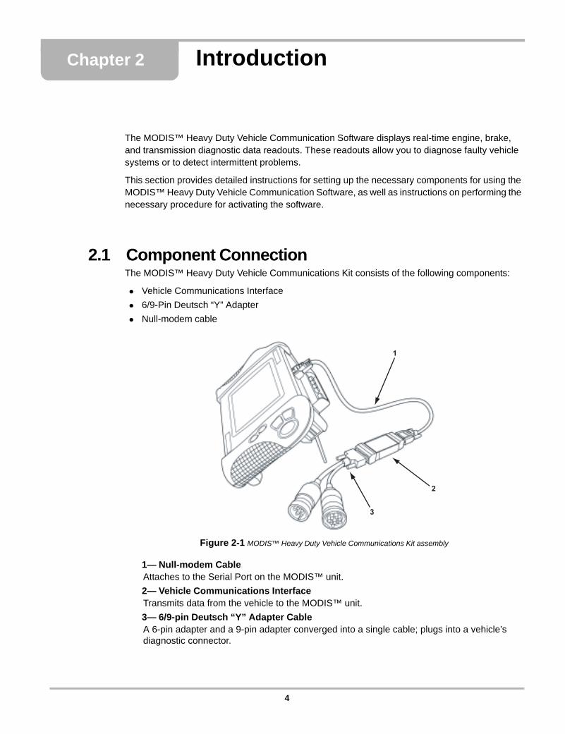
2.1 Component ConnectionThe MODIS™ Heavy Duty Vehicle Communications Kit consists of the following components:
• Vehicle Communications Interface
• 6/9-Pin Deutsch “Y” Adapter
• Null-modem cable
Figure 2-1 MODIS™ Heavy Duty Vehicle Communications Kit assembly
1— Null-modem CableAttaches to the Serial Port on the MODIS™ unit.
2— Vehicle Communications InterfaceTransmits data from the vehicle to the MODIS™ unit.
3— 6/9-pin Deutsch “Y” Adapter CableA 6-pin adapter and a 9-pin adapter converged into a single cable; plugs into a vehicle’s diagnostic connector.
1
2
3
4

Introduction Software Activation
z To connect the MODIS™ Heavy Duty Vehicle Communications Kit components:
1. Hold the female end of the null-modem cable so that the shorter side is on top (Figure 2-2 on page 5), then insert into the serial port on the MODIS™ unit.
Figure 2-2 Female end of the null-modem cable
IMPORTANT:IMPORTANT:Be sure to insert the null-modem cable into the serial port exactly as directed. Inserting the cable incorrectly can damage the MODIS™ unit.
2. Tighten the thumbscrews.
3. Attach the other (male) end of the null-modem cable to the 9-pin serial port on the Vehicle Communications Interface.
4. Attach the DB15 end of the 6/9-Pin Deutsch “Y” Adapter Cable to the 15-pin connector on the Vehicle Communications Interface.
5. Plug either the 6 or 9-pin adapter of the Deutsch “Y” Adapter Cable into the vehicle’s diagnostic connector.
NOTE:i The diagnostic connector is usually under the dashboard, near the steering column. However, on
newer trucks, the connector may be located near the door panel on the driver’s side.
2.2 Software ActivationThe MODIS™ Heavy Duty Vehicle Communication Software, is activated using optional CompactFlash® (CF) card media.
NOTE:i You must have the MODIS™ Software Bundle 4.1(or newer) installed on your MODIS™ unit, and
have purchased the optional software kit, in order to activate the MODIS™ Heavy Duty Vehicle Communication Software.
IMPORTANT:IMPORTANT:Interrupting the installation process can damage your unit! Do not interrupt the installation process, once it has started.
z To activate the MODIS™ Heavy Duty Vehicle Communication Software:
1. Plug one end of the 12-volt external AC power adapter into the 12–15V connector on top of the MODIS™ unit, and plug the other end of the adapter into an appropriate wall outlet.
2. Power up your MODIS™ diagnostic tool.
3. With the front of the MODIS™ CompactFlash® card facing you, insert the card into the top card slot on the diagnostic tool (Figure 1-3).
5

Introduction Software Activation
Figure 2-3 Top of MODIS™ unit and CF Card Slot
NOTE:i The card will easily fit into the slot only when inserted properly.
4. From the Main Menu, select Utilities > Software Update (Figure 1-4).
Figure 2-4 Sample Main Menu Screen—Utilities menu
A software installation dialog box displays specific information about the software update (Figure 1-5).
Figure 2-5 Sample—Software details dialog
5. Press Ya to continue the update.
A dialog box displays to indicate completion of installation (Figure 1-6).
Figure 2-6 Sample—Installation completion dialog
6. Remove the CompactFlash® card.
7. Press Ya to restart your MODIS™ unit.
6

Introduction Software Activation
7
Chapter 3 Navigation
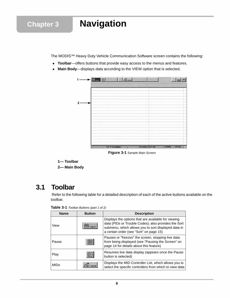
The MODIS™ Heavy Duty Vehicle Communication Software screen contains the following:
• Toolbar—offers buttons that provide easy access to the menus and features.
• Main Body—displays data according to the VIEW option that is selected.
Figure 3-1 Sample Main Screen
1— Toolbar
2— Main Body
3.1 Toolbar Refer to the following table for a detailed description of each of the active buttons available on the toolbar.
1
2
Table 3-1 Toolbar Buttons (part 1 of 2)
Name Button Description
View
Displays the options that are available for viewing data (PIDs or Trouble Codes); also provides the Sort submenu, which allows you to sort displayed data in a certain order (see “Sort” on page 15)
PausePauses or “freezes” the screen, stopping live data from being displayed (see “Pausing the Screen” on page 14 for details about this feature)
PlayResumes live data display (appears once the Pause button is selected)
MIDsDisplays the MID Controller List, which allows you to select the specific controllers from which to view data
8

Navigation Main Body
NOTE:i The buttons described above are the buttons that are enabled (“active”) for the current release of
this product. Buttons that appear disabled (“grayed-out”) are reserved for future releases.
3.2 Main BodyThe display on the main body varies, depending on the currently selected View option. Refer to the following section for an overview of the main body contents for each View option.
NOTE:i Regardless of the selected View option, no data displays on the screen until MID controllers have
been selected. Refer to “Selecting MIDs” on page 4 for details.
Data (PID) List View
The Data (PID) List view option provides a listing of all PIDs (Parameter Identifications) for a currently selected controller.
Figure 3-2 Sample Data List view
1— Controller Tabs—appear for each MID that is selected. See page 4 for details.
2— Data (PID) List—shows each parameter name and its current status. You can sort the parameter names to appear in a certain order. See “Sort” on page 15 for details.
Print Prints the data currently displayed on the screen
Setup Displays options to view units in English or Metric
Table 3-1 Toolbar Buttons (part 2 of 2)
Name Button Description
1
2
9

Navigation Main Body
Trouble Codes ViewThe Trouble Codes view option displays the current trouble codes for a selected controller, listed by PID number.
Figure 3-3 Sample Trouble Code view
1— Controller Tabs—appear for each MID that is selected (see page 4).
2— Trouble Code List—shows any detected trouble codes, listed by PID, for the currently selected controller.
3— Trouble Code Details Display—shows details of the selected Trouble Code.
3.2.1 Switching Between ViewsThe interface lets you switch between views (PIDs and Trouble Codes) without exiting.
z To switch between views:
1. Select View.
The drop-down menu displays (Figure 3-4).
Figure 3-4 Sample View submenu
2. Select the desired view.
NOTE:i A check mark appearing next to a view option indicates the option that is currently in effect.
The screen refreshes and displays according to the selected option.
1
2
3
10
Navigation Exiting the Application
3.3 Exiting the ApplicationExiting the application does not interrupt connection between the MODIS™ Heavy Duty Vehicle Communication Software and the vehicle. The application goes into “hibernate mode,” which allows you to go back into the application without having to re-establish a connection. Furthermore, if you exit the application, then open it again, the MIDs that were selected during the last session remain selected (and therefore displayed on the screen).
NOTE:i To completely discontinue communication between the MODIS™ Heavy Duty Vehicle
Communication Software and the vehicle, you will need to disconnect the Heavy Duty Communications Kit components (page 2) from the MODIS™ unit.
z To exit the application:
• Repeatedly press N/X until the MODIS™ main menu screen displays.
NOTE:i The number of times you will need to press the N/X button is dependent upon which part of the
screen you are currently navigating.
11

Chapter 4 Scanner Operations
This chapter provides detailed instructions on starting the MODIS™ Heavy Duty Vehicle Communication Software, and instructions for using the application’s features to view Data List and Trouble Code information from selected controllers.
4.1 Loading MODIS™ Heavy Duty Vehicle Communication SoftwareThe following steps provide instructions for loading the MODIS™ Heavy Duty Vehicle Communication Software from the MODIS™ main menu.
z To load the software:
1. Turn the vehicle’s ignition key to the ON position.
2. On the main menu (Figure 4-1), select Scanner > Heavy Duty Truck
Figure 4-1 Scanner selection from MODIS™ Main Menu
3. Select the desired option.
NOTE:i Once the application is loaded, you will be able to switch between the two options without having
to exit. Refer to “Switching Between Views” on page 5 for details.
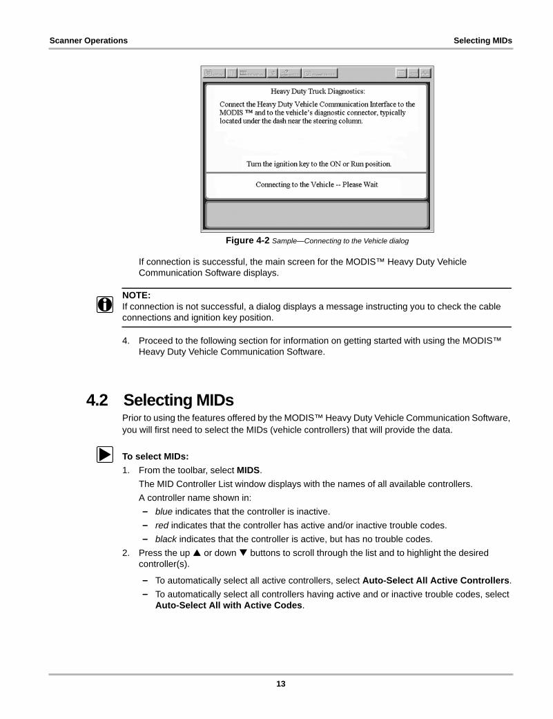
The screen shows a message indicating that the application is loading, followed by a reminder that all components must be connected (Figure 4-2).
12
Scanner Operations Selecting MIDs
Figure 4-2 Sample—Connecting to the Vehicle dialog
If connection is successful, the main screen for the MODIS™ Heavy Duty Vehicle Communication Software displays.
NOTE:i If connection is not successful, a dialog displays a message instructing you to check the cable
connections and ignition key position.
4. Proceed to the following section for information on getting started with using the MODIS™ Heavy Duty Vehicle Communication Software.
4.2 Selecting MIDsPrior to using the features offered by the MODIS™ Heavy Duty Vehicle Communication Software, you will first need to select the MIDs (vehicle controllers) that will provide the data.
z To select MIDs:
1. From the toolbar, select MIDS.
The MID Controller List window displays with the names of all available controllers.
A controller name shown in:
– blue indicates that the controller is inactive.
– red indicates that the controller has active and/or inactive trouble codes.
– black indicates that the controller is active, but has no trouble codes.
2. Press the up or down buttons to scroll through the list and to highlight the desired controller(s).
– To automatically select all active controllers, select Auto-Select All Active Controllers.
– To automatically select all controllers having active and or inactive trouble codes, select Auto-Select All with Active Codes.
13

Scanner Operations Selecting MIDs
Figure 4-3 Sample—MID Controller List screen
NOTE:i Despite its title, the Auto-Select All with Active Codes option shows controllers having active
and or inactive codes.
3. Press the Ya button to confirm the selection(s).
A check mark () displays to the left of the selected controller(s). See Figure 4-4.
Figure 4-4 Sample—MID Controller List with selected MIDs
NOTE:i To de-select a controller, press Ya again to remove the check mark.
4. Press N/X to confirm the selection of desired controller(s).
The MID Controller List disappears and the application’s main screen shows the selected controller names on tabs at the top of the screen, just below the toolbar (see Figure 4-5).
14

Scanner Operations Selecting MIDs
Figure 4-5 Sample—Screen showing controller tabs
NOTE:i The screen appearance varies according to the option selected in Step 2 of the procedure
provided on page 1 (“Load the MODIS™ Heavy Duty Vehicle Communication Software”).
4.2.1 Removing MIDsUse the following procedure to remove currently selected MIDs from the display.
z To remove MIDs:
1. On the toolbar, select MIDS.
The MID Controller List displays (Figure 4-6 on page 15).
Figure 4-6 Sample—MID Controller List screen
2. Use up or down buttons and the Ya button to de-select any controller name(s).
15

Scanner Operations Viewing Data Lists (PIDs)
3. Press N/X after de-selecting controllers.
The MID Controller List disappears and the application’s main screen refreshes, no longer showing the controller(s) you have removed.
4.3 Viewing Data Lists (PIDs)Once the desired MIDs are selected (see “Selecting MIDs” on page 13), you can view data list information for each MID that has been selected. Also, you can select specific parameters and place them in a “Locked List” at the top of the screen. This option allows you to keep specific parameters from specific controllers in constant view at the top of the screen.
4.3.1 Adding PIDs to a Locked ListUse the following instructions to add PID(s) to the Locked List view at the top of the screen.
z To add PIDs to a Locked List:
1. Select VIEW > PID List.
The screen refreshes and displays the PIDs for the currently selected controller(s) (Figure 1-9).
Figure 4-7 Sample—Data List (PID) screen
NOTE:i A brief delay may occur before all data is displayed for the selected MID.
2. Press the down arrow to move from the toolbar to the PID List.
3. Press the left and right arrows to move between tabs (controllers), as necessary.
NOTE:i A red >> indicates the currently selected tab (controller).
16
Scanner Operations Viewing Trouble Codes
4. Press the up or down arrows to highlight the PIDs that you wish to lock
5. Press Ya to lock the parameter and a check mark () displays to the left of the parameter name.
NOTE:i To de-select a parameter, press Ya again to remove the check mark.
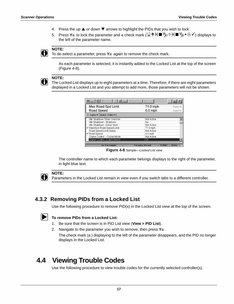
As each parameter is selected, it is instantly added to the Locked List at the top of the screen (Figure 4-8).
NOTE:i The Locked List displays up to eight parameters at a time. Therefore, if there are eight parameters
displayed in a Locked List and you attempt to add more, those parameters will not be shown.
Figure 4-8 Sample—Locked List view
The controller name to which each parameter belongs displays to the right of the parameter, in light blue text.
NOTE:i Parameters in the Locked List remain in view even if you switch tabs to a different controller.
4.3.2 Removing PIDs from a Locked ListUse the following procedure to remove PID(s) in the Locked List view at the top of the screen.
z To remove PIDs from a Locked List:
1. Be sure that the screen is in PID List view (View > PID List).
2. Navigate to the parameter you wish to remove, then press Ya.
The check mark (a) displaying to the left of the parameter disappears, and the PID no longer displays in the Locked List.
4.4 Viewing Trouble CodesUse the following procedure to view trouble codes for the currently selected controller(s).
17
Scanner Operations Viewing Trouble Codes
z To view trouble codes:
1. Select View > Trouble Codes.
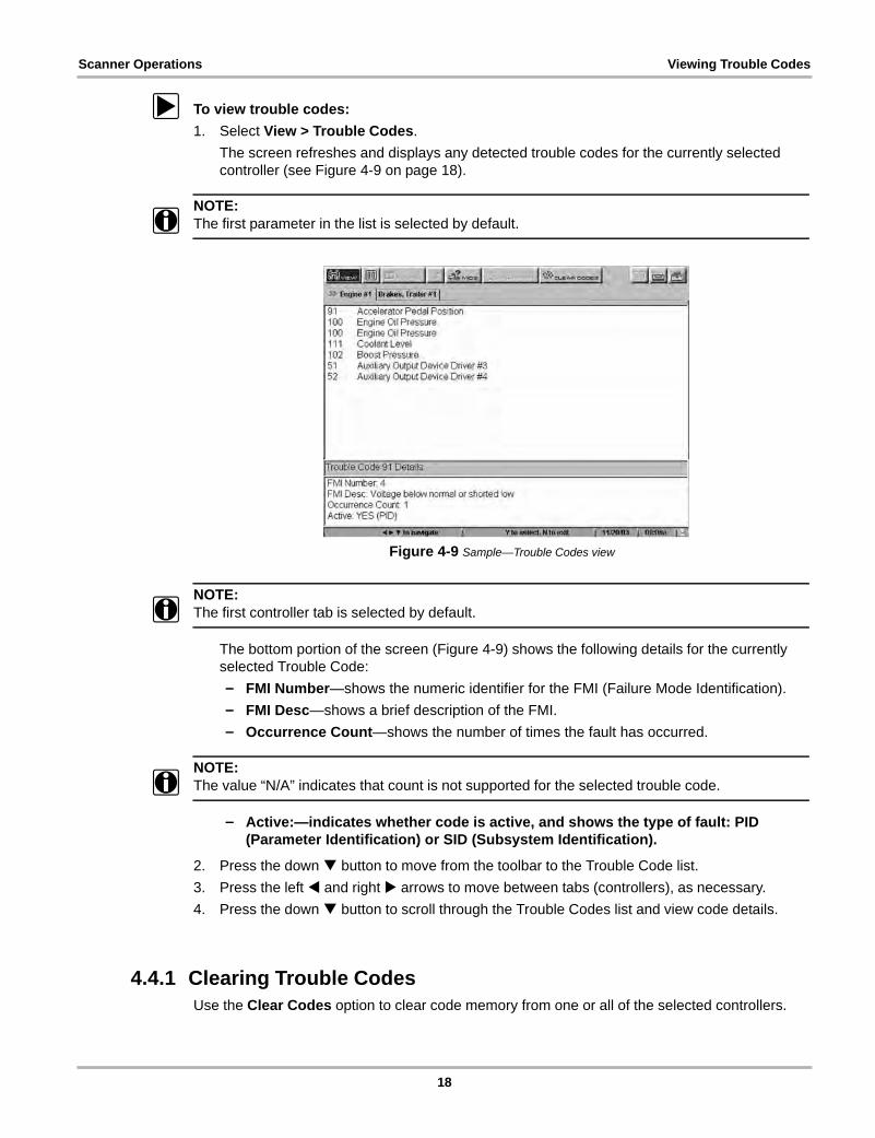
The screen refreshes and displays any detected trouble codes for the currently selected controller (see Figure 4-9 on page 18).
NOTE:i The first parameter in the list is selected by default.
Figure 4-9 Sample—Trouble Codes view
NOTE:i The first controller tab is selected by default.
The bottom portion of the screen (Figure 4-9) shows the following details for the currently selected Trouble Code:
– FMI Number—shows the numeric identifier for the FMI (Failure Mode Identification).
– FMI Desc—shows a brief description of the FMI.
– Occurrence Count—shows the number of times the fault has occurred.
NOTE:i The value “N/A” indicates that count is not supported for the selected trouble code.
– Active:—indicates whether code is active, and shows the type of fault: PID (Parameter Identification) or SID (Subsystem Identification).
2. Press the down button to move from the toolbar to the Trouble Code list.
3. Press the left and right arrows to move between tabs (controllers), as necessary.
4. Press the down button to scroll through the Trouble Codes list and view code details.
4.4.1 Clearing Trouble CodesUse the Clear Codes option to clear code memory from one or all of the selected controllers.
18

Scanner Operations Pausing the Screen
z To clear trouble codes:
1. Select Clear Codes.
The drop-down menu displays (Figure 4-10).
Figure 4-10 Sample—Clear Codes submenu
2. Select the desired option.
A confirmation message displays (Figure 4-11).
Figure 4-11 Clear codes success message
3. Press Ya to continue.
4.5 Pausing the ScreenThe Pause button lets you pause (or “freeze”) the screen so that it stops live data from being displayed. Once you select this option, the Play button (Figure 4-12) replaces the Pause button (Figure 4-13), which lets you return to the live data display.
Figure 4-12 Sample—Toolbar before Pause selection
1— Pause Button
Figure 4-13 Sample—Toolbar after Pause selection
1— Play Button
Use the PAUSE button to print the screen’s display (see “Printing the Current Screen” on page 19 for details). However, keep the following in mind when pausing the screen:
• Trouble codes cannot be cleared while the screen is paused.
• If you exit the application after selecting Pause, then you re-enter the application, the screen will no longer be paused (that is, it shows live data).
19

Scanner Operations Data View Options
4.6 Data View OptionsWhether viewing PIDs or trouble codes, the MODIS™ Heavy Duty Vehicle Communication Software lets you specify the order in which data is displayed on the screen, and also lets you specify the format in which the units of measure are displayed (English or Metric).
4.6.1 Sort
Use the Sort option to display data in one of the following orders:
• Factory—displays data in the order in which it is received from the vehicle.
NOTE:i Factory is the default sort order.
• Ascending—sorts PID Lists alphabetically from A to Z and trouble codes numerically from lowest to highest.
• Descending—sorts PID Lists alphabetically from Z to A and trouble codes numerically from highest to lowest.
NOTE:i Different sort orders may be used for data lists and trouble codes simultaneously. That is, the sort
order specified for PID List does not affect the sort order specified for trouble codes.
NOTE:i The sort order that you specify remains in effect for the currently selected View option (PID List or
Trouble Codes) until you change it.
z To sort displayed data:
1. Select View > Sort By.
The drop-down submenu displays (Figure 4-14 on page 20).
Figure 4-14 Sample—Sort submenu options
20
Scanner Operations Data View Options
2. Select the desired sort method.
The screen refreshes, showing the data sorted according to the format you selected.
4.6.2 SetupYou can specify the format in which units of measure (US Customary or metric) are displayed on the screen, from either of the following locations:
• Utilities—located on the main menu
• Settings—located on the upper toolbar
NOTE:i The format that you specify remains in effect until you change it.
z To specify the unit of measure format:
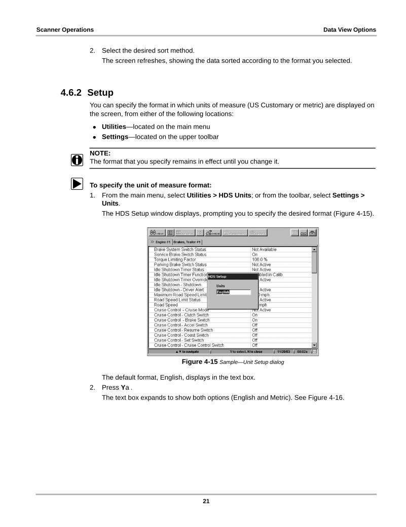
1. From the main menu, select Utilities > HDS Units; or from the toolbar, select Settings > Units.
The HDS Setup window displays, prompting you to specify the desired format (Figure 4-15).
Figure 4-15 Sample—Unit Setup dialog
The default format, English, displays in the text box.
2. Press Ya.
The text box expands to show both options (English and Metric). See Figure 4-16.
21
Scanner Operations Printing the Current Screen
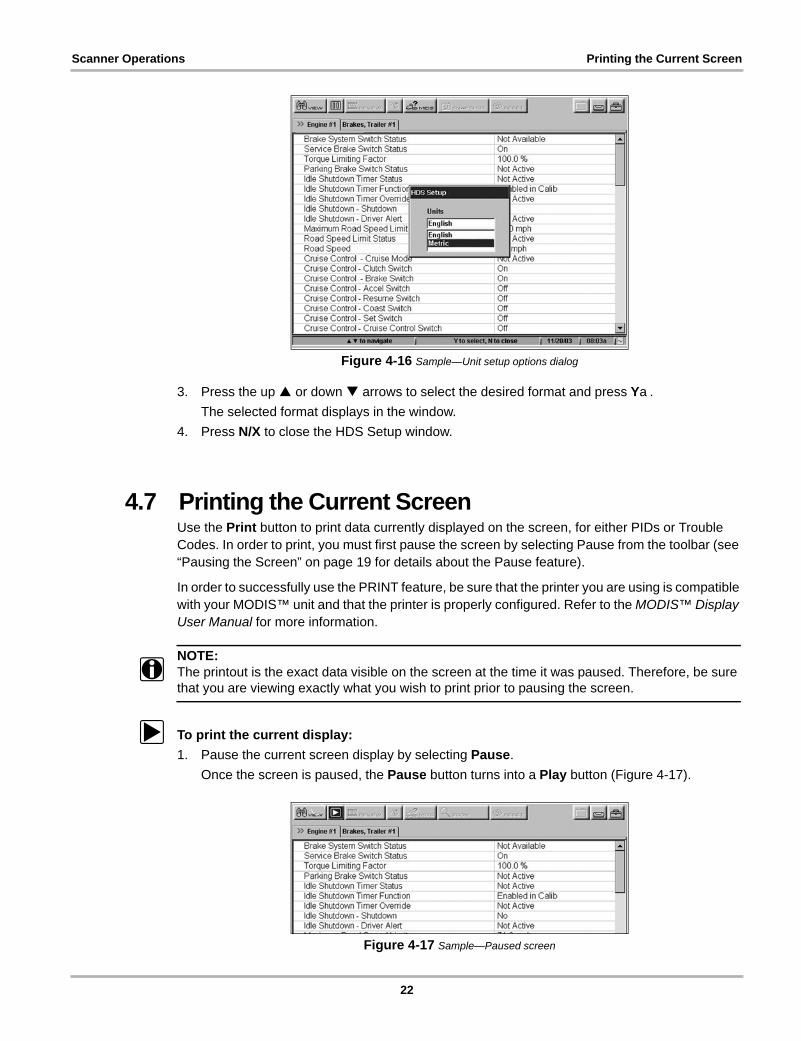
Figure 4-16 Sample—Unit setup options dialog
3. Press the up or down arrows to select the desired format and press Ya.
The selected format displays in the window.
4. Press N/X to close the HDS Setup window.
4.7 Printing the Current ScreenUse the Print button to print data currently displayed on the screen, for either PIDs or Trouble Codes. In order to print, you must first pause the screen by selecting Pause from the toolbar (see “Pausing the Screen” on page 19 for details about the Pause feature).
In order to successfully use the PRINT feature, be sure that the printer you are using is compatible with your MODIS™ unit and that the printer is properly configured. Refer to the MODIS™ Display User Manual for more information.
NOTE:i The printout is the exact data visible on the screen at the time it was paused. Therefore, be sure
that you are viewing exactly what you wish to print prior to pausing the screen.
z To print the current display:
1. Pause the current screen display by selecting Pause.
Once the screen is paused, the Pause button turns into a Play button (Figure 4-17).
Figure 4-17 Sample—Paused screen
22

Scanner Operations Losing Connection
2. Holding the MODIS™ unit, point the Infrared Output at the printer.
3. Select Print from the toolbar.
The drop-down menu displays (Figure 4-18).
Figure 4-18 Sample—PRINT menu
4. Press Ya to select Page.
A dialog displays, indicating that the printing operation is being initialized (Figure 4-19).
Figure 4-19 Sample—Initializing Printer Dialog
NOTE:i A delay of approximately 30 seconds may occur from the time you select Page, to the time this
dialog displays.
Once the printer is successfully initialized, a new dialog displays, indicating that printing is in progress(Figure 4-20).
Figure 4-20 Sample—Printing progress dialog
5. To print another page (with different data), select Play, then repeat this procedure from Step 1.
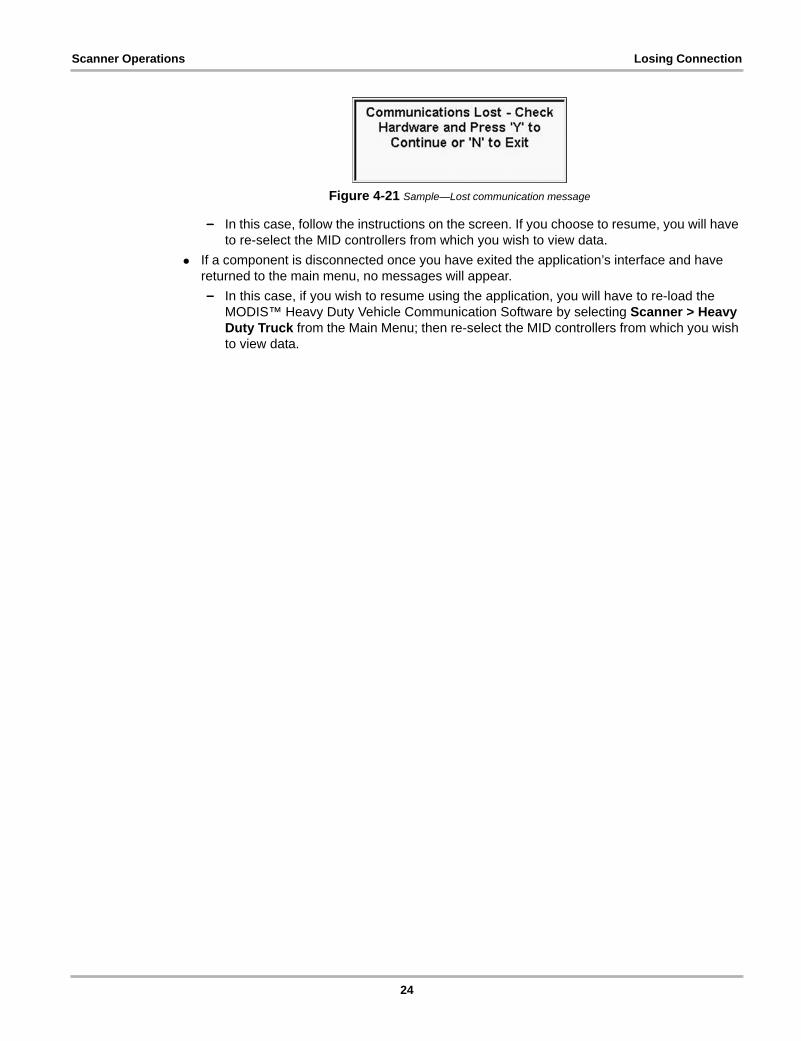
4.8 Losing ConnectionIf, for any reason, a hardware component is disconnected while you are using the MODIS™ Heavy Duty Vehicle Communication Software, communication between the vehicle and the MODIS™ unit will be stopped, and any selections you made up to that point are cleared.
• If a component is disconnected while you are navigating the application, a message displays(Figure 4-21).
23
Scanner Operations Losing Connection
Figure 4-21 Sample—Lost communication message
– In this case, follow the instructions on the screen. If you choose to resume, you will have to re-select the MID controllers from which you wish to view data.
• If a component is disconnected once you have exited the application’s interface and have returned to the main menu, no messages will appear.
– In this case, if you wish to resume using the application, you will have to re-load the MODIS™ Heavy Duty Vehicle Communication Software by selecting Scanner > Heavy Duty Truck from the Main Menu; then re-select the MID controllers from which you wish to view data.
24

Appendix A PIDs Not Supported
Refer to the following table for a listing of PIDs that are not supported by this release of the MODIS™ Heavy Duty Vehicle Communication Software.
NOTE:i For a complete listing of all J1587 PIDs, refer to the SAE (Society of Automotive Engineers) J1587
Recommended Practice specifications
Table A-1 PIDs Not Supported
PID Parameter Name
210 Tire temperature (by sequence number)
211 Tire pressure (by sequence number)
212 Tire pressure target (sequence number)
213 Wheel end assembly vibration level
215 Brake temperature
216 Wheel bearing temperature
217 Fuel tank/nozzle identification
218 State line crossing
219 Current state and country
220 Engine torque history
223 Auxiliary A/D counts
224 Immobilizer security code
225 Reserved for text message acknowledged
226 Reserved for text message to display
227 Reserved for text message display type
232 DGPS differential correction
238 Velocity vector
239 Vehicle position
240 Change reference number
241 Tire pressure by position
242 Tire temperature by position
367 Lane tracking system status
368 Lane departure indication
378 Fare collection unit status
381 Vehicle use status
382 Transit silent alarm status
435 Cargo ambient temperature (by location)
447 Passenger counter
25

PIDs Not Supported
500Intersection preemption status and configuration
501 Signage message
502 Fare collection unit-point of sale
503 Fare collection unit-service detail
504 Annunciator voice message
505 Vehicle control head keyboard message
506 Vehicle control head display message
507 Driver identification
508 Transit route identification
509 Mile post identification
Table A-1 PIDs Not Supported
PID Parameter Name
26

Index
Bbold text, 1
Ccomponent connection, 4controllers. See MIDs
Ddata view options, 20
Setup, 21Sort, 20
LLocked List
adding PIDs to, 16removing PIDs from, 17
losing connection, 23
Mmain body, 9manual conventions, 1–3manuals, additional, 3messages, 2
important, 2note, 2
MIDs, 13removing, 15selecting, 13
Nnavigation
toolbar, 8
Ppausing screen display, 19PIDs
not supported (listing), 25See also Locked Listviewing, 16
printcurrent screen, 22setup, 22
procedures, 2
SSafety, iii–ivsafety
information, iiisoftware
activating, 5exiting, 11loading, 12
sorting data, 20symbols, 1
Tterminology, 2tool help, 3toolbar
buttons, 8trouble codes
clearing, 18viewing, 17
VVehicle Communications Interface
cables for, 4installing, 4
viewingdata (PID) lists, 9trouble codes, 10
27