Embed Size (px)
Citation preview
IJST, Transactions of Mechanical Engineering, Vol. 37, No. M1, pp 39-51 Printed in The Islamic Republic of Iran, 2013 © Shiraz University
HEAT TRANSFER AUGMENTATION IN PLATE FINNED TUBE HEAT EXCHANGERS WITH VORTEX GENERATORS: A COMPARISON
OF ROUND AND FLAT TUBES*
M. MIRZAEI1 AND A. SOHANKAR2** 1Department of Mechanical Engineering, Yazd University, Yazd, I. R. of Iran
2Department of Mechanical Engineering, Isfahan University of Technology, Isfahan, I. R. of Iran Emai: [email protected]
Abstract– Heat transfer augmentation and pressure loss penalty caused by vortex generators (VGs) are numerically studied for finned flat/round tube heat exchangers and compared with available experimental results. The simulations are performed with the steady three-dimensional incompressible conditions and a RNG K-ε turbulence model is used. The Reynolds numbers based on the bulk velocity and the height of channel are selected from 600 to 4050. To compare the effectiveness of VGs on the round and flat tubes for tube-fin heat exchangers, two different configurations are investigated with two and four delta winglet vortex generators for each tube. The streamlines, vorticity, the averaged Nusselt number, the friction factor and the performance factor (JF) are provided to evaluate the effectiveness of VGs for the heat exchangers employed. It is found that the flat tube with VGs provides better thermal performance than the round one, especially at the lower Reynolds numbers.
Keywords– Tube-fin heat exchanger, heat transfer enhancement, flat tube, round tube, vortex generator
1. INTRODUCTION
Tube-fin heat exchangers are mostly employed as gas-to-liquid exchangers. Nowadays, many applications such as chemical, petroleum industries, thermal processing systems in automotive, refrigeration and air conditioning are found for tube-fine exchangers. Depending on the fin type, these exchangers are referred to as finned tube exchangers (having normal fins on individual tube) and tube-fin exchangers (having flat continuous fins). In these exchangers, the fins can be plain, wavy, or interrupted, while round, flat and oval tubes may be used. A tube-fin exchanger with flat fins is referred to as a plate finned tube [1], (Fig. 1). Apart from the flow structure, geometrical parameters such as tube form (round or flat tube), arrangement (inline or staggered), and tube and fin spacing are effective in the performance of these exchangers. For example, with an inline arrangement, the horseshoe vortices may not be generated in front of the tubes of the second and the other rows, while in the staggered arrangement, the horseshoe vortices appear in front of each tube, which can influence the flow structure on the large area of the fin.
In recent years, vortex generators such as fins, ribs, wings etc. have been successfully used for heat transfer enhancement of the modern thermal systems. Vortex generators form secondary flow by swirl and destabilize the flow. They generate the longitudinal vortices and create rotating and secondary flow in the main flow which can raise turbulent intensity, mix the warm and cold fluid near and in the center of channel and increase the heat transfer in the heat exchangers. Different types of vortex generators such as
Received by the editors February 8, 2012; Accepted December 9, 2012. Corresponding author
M. Mirzaei and A. Sohankar
IJST, Transactions of Mechanical Engineering, Volume 37, Number M1 April 2013
40
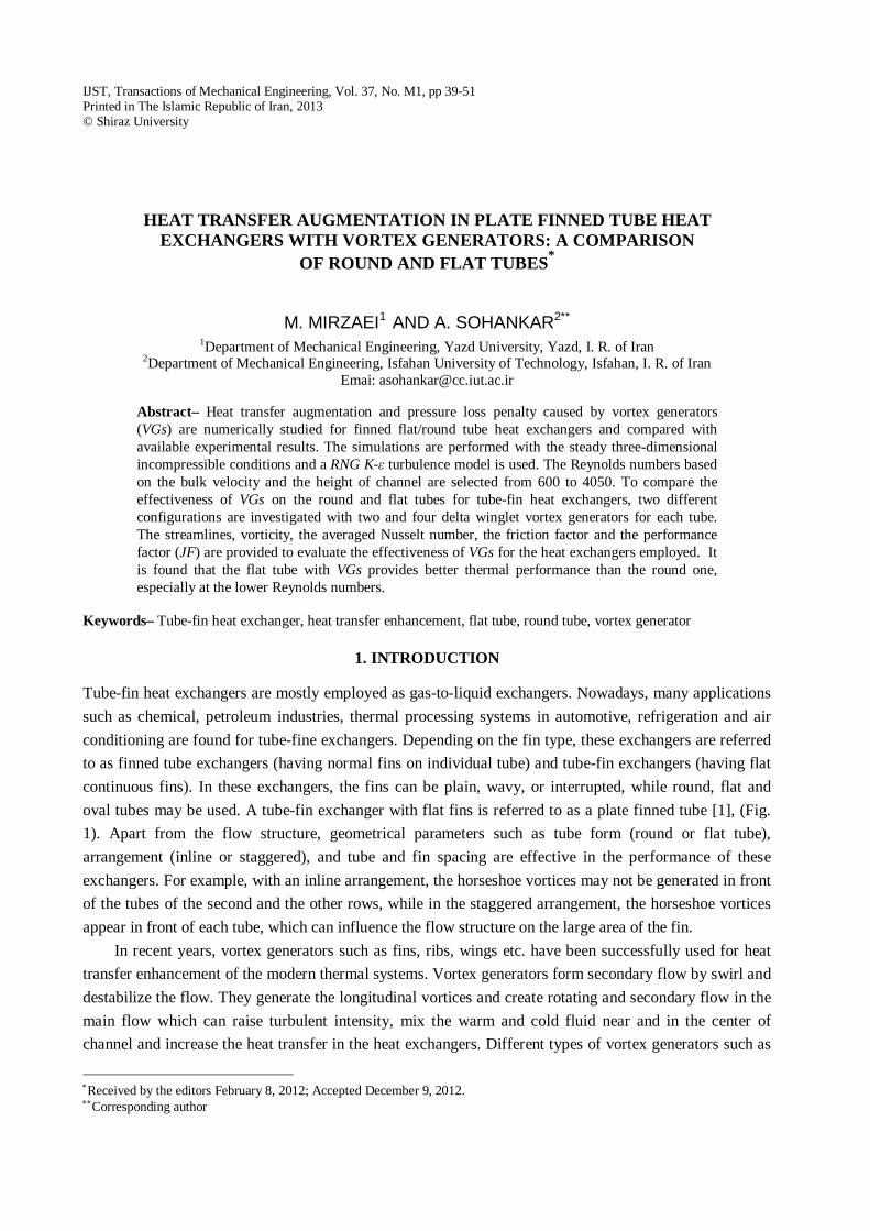
rectangular and triangular wings and winglets have been considered for heat transfer enhancement by researchers [2-11]. A typical finned flat and round tube bank with vortex generators is presented in Fig. 1.
Fig.1. Schematic view of tube-fin heat exchangers with vortex generators.
Right: flat tube [5], Left: round tube [4] Torri et al., recommended a ‘‘common flow up’’ configuration for vortex generators that can
augment the heat transfer and reduce the pressure-loss in a fin-tube heat exchanger with circular tubes [2, 3]. Their experimental results for the Reynolds numbers between 350 and 2100 showed that ‘‘common flow up’’ vortex generators in a staggered arrangement of tubes increased heat transfer about 10–30%, and reduced the pressure drop about 34–55%. In the case of in-line arrangement, the heat transfer augmentation and pressure drop reduction were reported to be about 10–20% and 8–15%, respectively [2,3].
In 1994, Fiebig et al. [4] experimentally compared the effect of vortex generators on the heat transfer and flow losses in fin-flat/round tube heat exchangers for the Reynolds number between 600 and 3000. For the staggered fin-tube arrangement, their results showed that the heat exchanger element with round tubes and vortex generators increase heat transfer only 10%, but about 100% for flat tube. They also showed that pressure drop in flat tube bank with vortex generator is nearly half that for the round tube bank with vortex generator.
The effect of two pairs of vortex generator in a flat tube bank for the Reynolds number between 900 and 4050 was studied experimentally by Wang et al. [5]. They showed that heat transfer enhancement in flat tube bank with and without vortex generator for constant mass flow, constant power consumption and constant pressure drop is 47.5%, 41.4% and 37.5%, respectively. The effect of geometrical parameters such as fin space, vortex generator height and angle on heat transfer enhancement were studied numerically/experimentally in a finned flat tube band [6-8]. The insight that comes from these papers is that the relative position of VGs in the channel is a very important parameter that should be carefully considered in design of such heat transfer enhancement surfaces.
The unsteady flow and heat transfer were simulated using LES and DNS for a channel with two angled ribs as a vee-shaped vortex generator to augment heat transfer [9-11]. The vortex generators are attached on the bottom wall of the channel and their angles with respect to the main flow are between 10 and 30. The Reynolds numbers based on the inflow velocity and the height of channel are from 200 to 2000. A comparison between the DNS and LES results was performed and it was found that relatively similar results are obtained from a LES simulation with fine grid and a DNS simulation with finer grid. Thermal performance parameter, JF, was used as a measure for the amount of the heat transfer enhancement relative to the pressure drop. This work showed that the JF value increases as the Reynolds number or the incidence angles increase.
The purpose of the present numerical research is to investigate the effect of vortex generator in finned flat and round tube bank. Despite the large number of studies on the effects of vortex generators for finned flat or round tubes, to the best of our knowledge, there is not any published work, except experimental
Heat transfer augmentation in plate finned tube heat…
April 2013 IJST, Transactions of Mechanical Engineering, Volume 37, Number M1
41
study of Ref.[4], to compare a similar configuration with round and flat tube. Hence, the motivation for the present numerical study is the obvious lack of numerical information concerning such a comparison. The aim is to show for what type of tubes (flat or round) the vortex generators work more effectively for heat transfer enhancement and pressure loss penalty.
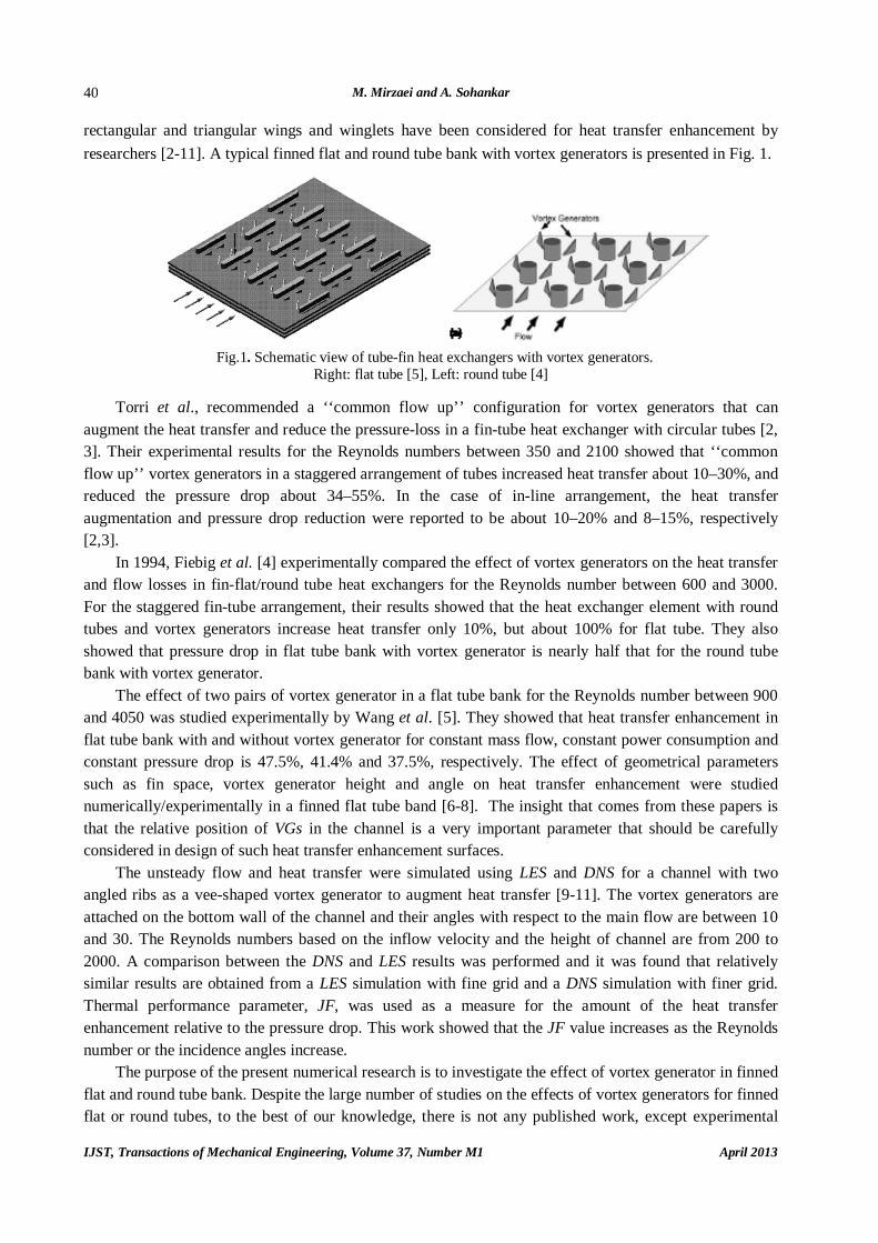
2. PROBLEM DESCRIPTION AND NUMERICAL DETAILS In the present work, two different configurations for tube-fin heat exchangers are investigated. A schematic view of a flat/ round tube-fin heat exchanger with vortex generators is shown in Fig. 1. The first configuration is chosen exactly similar to that employed by Fiebig et al. [4]. In this configuration, a pair of delta winglet vortex generators is used for each tube (see Fig. 2 and Table 1). The second configuration is chosen approximately similar to that selected by Wang et al. [5], (Fig. 3). It is important to note that Wang et al. [5] employed four delta winglet vortex generators in their model, while in the present study a pair of vortex generators is also employed around each tube to provide equal number of the vortex generators similar to those chosen by Fiebig et al. [4]. It should be mentioned that all geometric parameters for the second configuration and the Wang et. al. [5] model are exactly equal and the main difference is the number of chosen vortex generators.
Fig. 2. Schematic view of the fin-and-tube channels in Fiebig model.
Left: round tubes, Right: flat tubes [4]
Table 1. Dimensions in Fiebig model [4], see Fig. 2
Parameter magnitude Parameter definition Parameter name 32 mm Round tube diameter D 7 mm Channel height H 12 mm Width of flat tube b
69.6 mm Length of flat tube a 45º Attack angle β
Fig. 3. Flat tube bank arrangement and position of four vortex generators around each tube in Wang et al. model [5]
M. Mirzaei and A. Sohankar
IJST, Transactions of Mechanical Engineering, Volume 37, Number M1 April 2013
42
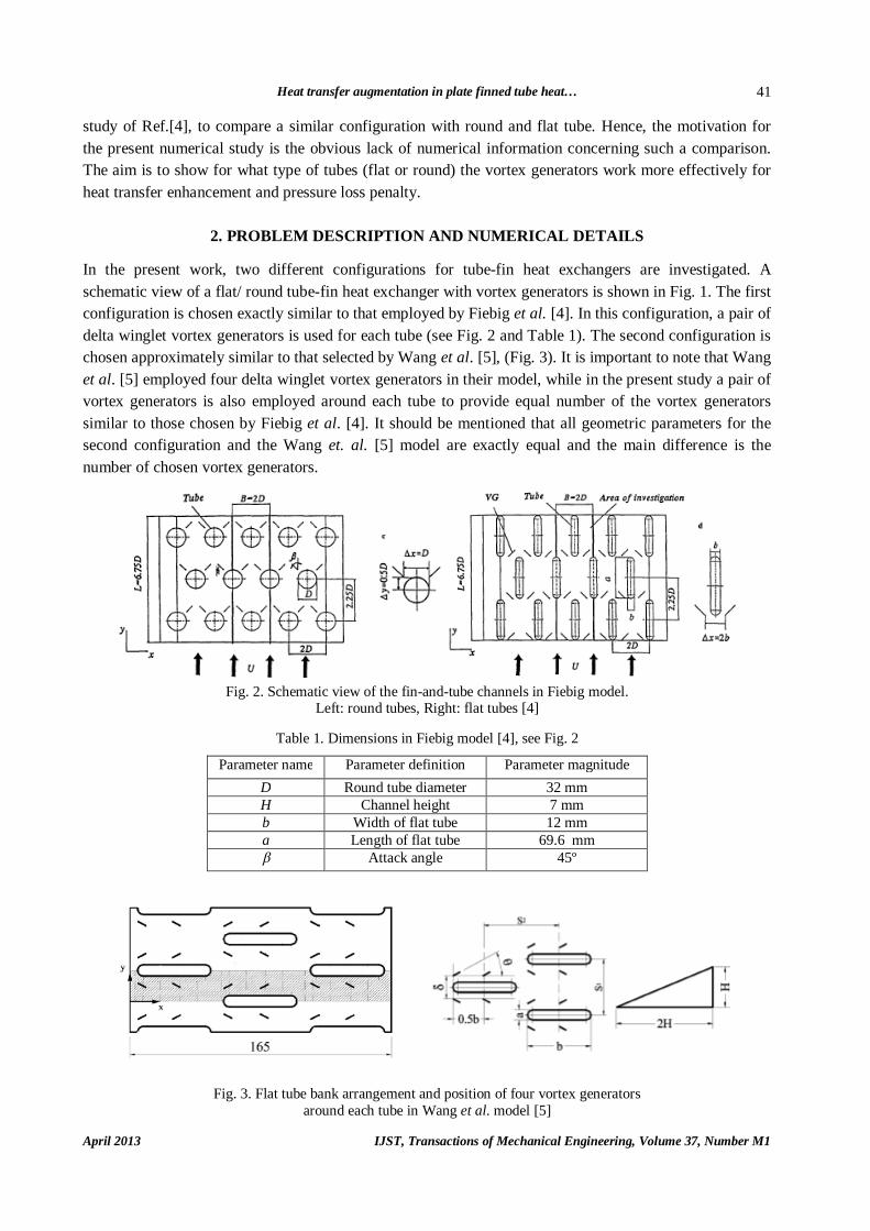
The calculation domains of the flat and round tubes, the position and the geometry of the vortex generators for both configurations are shown in Fig. 4. This geometry can be specified by the parameters such as the tube length, b, the tube width, a, the spacing between tubes, the distance between two vortex generators beside the same tube, the angle of attack, the length and height of the vortex generator. All geometric parameters for the first configuration are selected similar to those employed by Fiebig et al. [4], see Fig. 2 and Table 1. The geometric parameters used by Wang et al. [5] are adopted in this work for the second configuration, i.e. S1=40 mm, S2=55 mm, b=46.3 mm, a=6.3 mm, H = 4 mm, h = 35 mm, Tp= 5 mm, and the aspect ratio is selected as 2 (aspect ratio is =Λ (2h)2/hl, h is height and l is width of vortex generator).
Fig. 4. Calculation domains for round and flat tube channels with a pair of vortex generators around
each tube. Dimensions are chosen based on, left: Wang model [5], right Fiebig model [4] In the present study, the flow and heat transfer are assumed to be 3D, steady, incompressible and with
constant fluid properties. The numerical simulations are performed by solving the time-averaged continuity, momentum, energy equations and RNG K-ε turbulence model with a commercial code (Fluent). It should be noted that the RNG (Re-Normalization Group) model was developed to account for the effects of smaller scales of motion. In the standard K-ε model, the eddy viscosity is determined by a single turbulence length scale, so the calculated turbulent diffusion occurs at the specified scales, whereas in reality all scales of motion will contribute to the turbulent diffusion.
The following boundary conditions are used for two configurations. A uniform flow ( inUu , kTT in 313 ) at the inlet and fully developed condition for velocity and temperature are used at the outlet. The no-slip condition is used on the walls (tubes and channel walls surfaces). The temperature of the surfaces is chosen to be constant ( kTT w 2.353 ) and the symmetry condition is used in the span-wise direction (Fig. 4).
A schematic view of the grids used around a flat/round tube and around a vortex generator is shown in Fig. 5. Because of the symmetric geometry of the round and flat tube bank, the grids are only generated for half of the domains. An un-structural grid with triangular cells is used for round and flat tubes. The Reynolds number is adopted based on two different definitions (Rew, Ref). In the Wang model [5], the Reynolds number is defined based on the hydraulic diameter, hd , and the maximum velocity, mu , where
p
ph TaS
TaSd
2)(2)(4
1
1
,
hm
wdu
Re (1)
In this study, Rew is chosen between 1240 and 8370. In the Fiebig model [4], for equal inlet condition in both round and flat tubes, the Reynolds number is
defined based on the channel height (the distance between the fins), H, and inlet velocity, inu , where,
Huin
f Re (2)
Heat transfer augmentation in plate finned tube heat…
April 2013 IJST, Transactions of Mechanical Engineering, Volume 37, Number M1
43
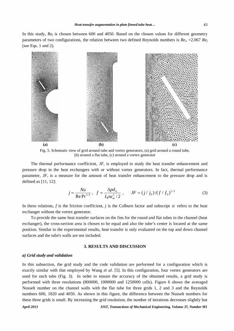
In this study, Ref is chosen between 600 and 4050. Based on the chosen values for different geometry parameters of two configurations, the relation between two defined Reynolds numbers is Rew =2.067 Ref (see Eqs. 1 and 2).
(a) (b) (c)
Fig. 5. Schematic view of grid around tube and vortex generators, (a) grid around a round tube, (b) around a flat tube, (c) around a vortex generator
The thermal performance coefficient, JF, is employed to study the heat transfer enhancement and
pressure drop in the heat exchangers with or without vortex generators. In fact, thermal performance parameter, JF, is a measure for the amount of heat transfer enhancement to the pressure drop and is defined as [11, 12]:
3/1PrReNuj ,
2/2m
h
uLpdf
, 3/100 )//()/( ffjjJF (3)
In these relations, f is the friction coefficient, j is the Colburn factor and subscript o refers to the heat exchanger without the vortex generator.
To provide the same heat transfer surfaces on the fins for the round and flat tubes in the channel (heat exchanger), the cross-section area is chosen to be equal and also the tube’s center is located at the same position. Similar to the experimental results, heat transfer is only evaluated on the top and down channel surfaces and the tube's walls are not included.
3. RESULTS AND DISCUSSION a) Grid study and validation In this subsection, the grid study and the code validation are performed for a configuration which is exactly similar with that employed by Wang et al. [5]. In this configuration, four vortex generators are used for each tube (Fig. 3). In order to ensure the accuracy of the obtained results, a grid study is performed with three resolutions (800000, 1000000 and 1250000 cells). Figure 6 shows the averaged Nusselt number on the channel walls with the flat tube for three grids 1, 2 and 3 and the Reynolds numbers 600, 1820 and 4050. As shown in this figure, the difference between the Nusselt numbers for these three grids is small. By increasing the grid resolution, the number of iterations decreases slightly but

M. Mirzaei and A. Sohankar
IJST, Transactions of Mechanical Engineering, Volume 37, Number M1 April 2013
44
the time convergence severely increases. Because a little difference between the results is found for the three resolutions, grid 1 is also used for all simulations in this research for flat tube bank with a pair of vortex generators (Fig. 4). The results obtained with this resolution are also compared with available experimental data [5]. Figs. 7a and 7b show the comparison of the averaged Nusselt number and friction factor with the experimental results of Wang et al. [5] for a flat tube bank with four vortex generators. These results are provided for both cases with and without vortex generator in the Reynolds number 600- 4050 (Fig. 5). As seen in these figures, for both cases with and without the vortex generator, the experimental and the present results behave in a similar way, where the Nusselt numbers and friction factor increase/decrease with the increase in the Reynolds numbers. Also, a higher Nusselt number and friction factor are obtained for cases with the vortex generators. The present and experimental results for the Nusselt number and friction factor for cases with and without vortex generator behave in a similar manner (Fig. 7). It should be noted that Wang et al. [5] compared their numerical and experimental results for the same configuration with the vortex generators. They reported a difference about 32% between their numerical and experimental results for the friction factor.
0
5
10
15
20
25
30
0 1000 2000 3000 4000 5000
Rew
Nuss
elt N
umbe
r
grid-1 grid-2 grid-3
Fig. 6. Nusselt numbers for three resolutions versus Reynolds numbers for the Wang et al. [5]
model with four vortex generators around each tube
Fig. 7. Comparison of averaged (a) Nusselt number and (b) friction factor with the experimental
results [5] for flat tube bank with and without vortex generator for the Reynolds number between 600 and 4050 (Rew)
b) Flow structure: A comparison of round and flat tubes
In this subsection and the next one, the effectiveness of the vortex generator on the round and flat tubes heat exchangers is investigated for two different configurations (Fig. 4). The first configuration is chosen exactly similar to that employed by Fiebig et al. [4]. In this configuration, a pair of delta winglet vortex generators is used for each tube. The second configuration is chosen approximately similar to that selected by Wang et al. [5]. Wang et al. [5] employed four delta winglet vortex generators in their model,
Heat transfer augmentation in plate finned tube heat…
April 2013 IJST, Transactions of Mechanical Engineering, Volume 37, Number M1
45
while in the present study a pair of vortex generators is employed around each tube to provide an equal number of vortex generators similar to those chosen by Fiebig et al. [4]. It should be mentioned that all geometric parameters for the second configuration are exactly equal to those that were employed by Wang et. al. [5] and the main difference is the number of the vortex generators chosen.
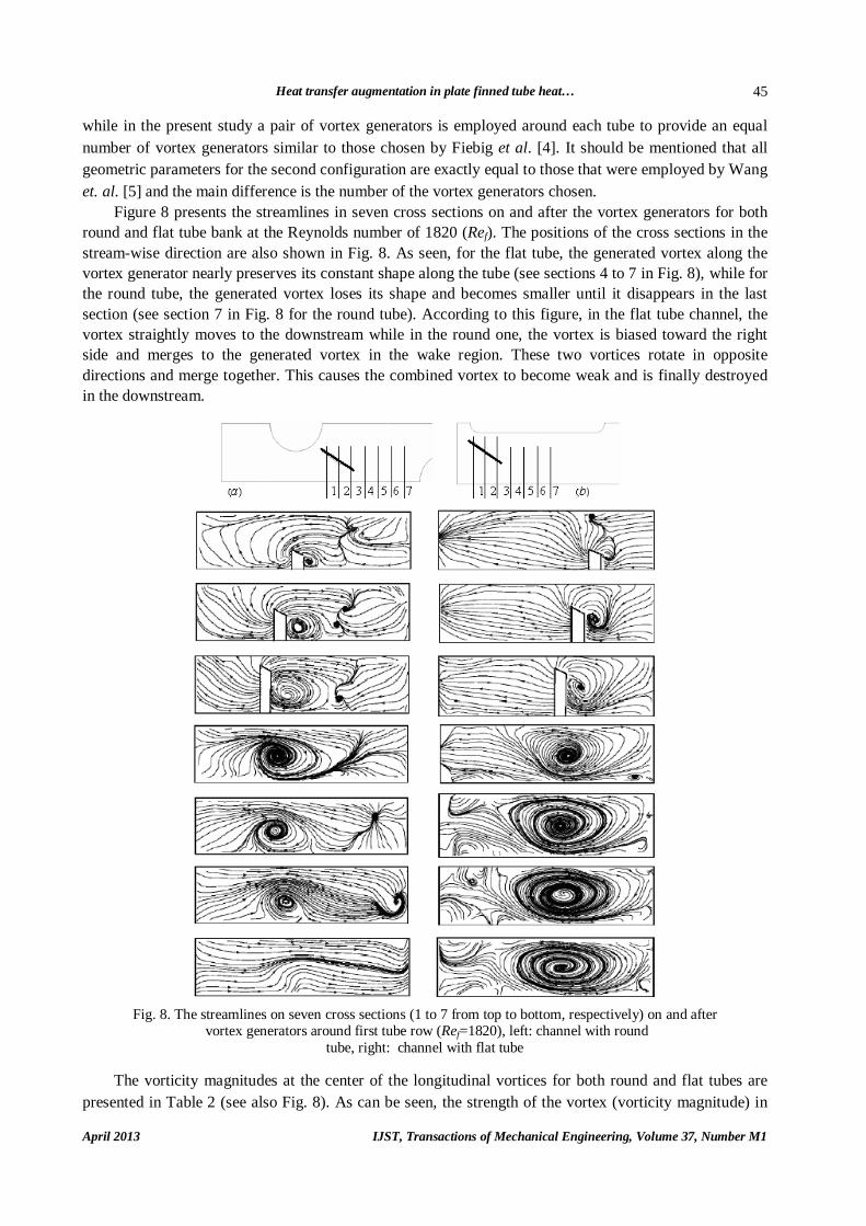
Figure 8 presents the streamlines in seven cross sections on and after the vortex generators for both round and flat tube bank at the Reynolds number of 1820 (Ref). The positions of the cross sections in the stream-wise direction are also shown in Fig. 8. As seen, for the flat tube, the generated vortex along the vortex generator nearly preserves its constant shape along the tube (see sections 4 to 7 in Fig. 8), while for the round tube, the generated vortex loses its shape and becomes smaller until it disappears in the last section (see section 7 in Fig. 8 for the round tube). According to this figure, in the flat tube channel, the vortex straightly moves to the downstream while in the round one, the vortex is biased toward the right side and merges to the generated vortex in the wake region. These two vortices rotate in opposite directions and merge together. This causes the combined vortex to become weak and is finally destroyed in the downstream.
Fig. 8. The streamlines on seven cross sections (1 to 7 from top to bottom, respectively) on and after
vortex generators around first tube row (Ref=1820), left: channel with round tube, right: channel with flat tube
The vorticity magnitudes at the center of the longitudinal vortices for both round and flat tubes are
presented in Table 2 (see also Fig. 8). As can be seen, the strength of the vortex (vorticity magnitude) in
M. Mirzaei and A. Sohankar
IJST, Transactions of Mechanical Engineering, Volume 37, Number M1 April 2013
46
the flat tube is more than that for the round one. Thus, the effect of the generated vortices on the increase of the heat transfer in the flat tube bank is more than that for the round one. Also, from these results, it is observed that the strength of the vortices in the flat tube changes more gradually than those for the round one.
Table 2. Vorticity magnitude at the center of longitudinal vortices in the round
and flat tubes (Ref=1820), see also Fig. 8
Section Flat tube(1/s) Round tube(1/s) 1 13855 12193 2 6084 4845 3 3560 3037 4 2576 1580 5 2256 1153 6 1520 854 7 1026 -
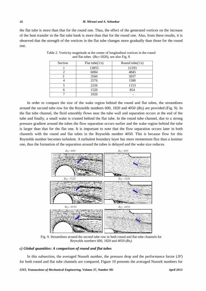
In order to compare the size of the wake region behind the round and flat tubes, the streamlines
around the second tube row for the Reynolds numbers 600, 1820 and 4050 (Ref) are provided (Fig. 9). In the flat tube channel, the fluid smoothly flows near the tube wall and separation occurs at the end of the tube and finally, a small wake is created behind the flat tube. In the round tube channel, due to a strong pressure gradient around the tubes the flow separation occurs earlier and the wake region behind the tube is larger than that for the flat one. It is important to note that the flow separation occurs later in both channels with the round and flat tubes in the Reynolds number 4050. This is because flow for this Reynolds number becomes turbulent. A turbulent boundary layer has more momentum flux than a laminar one, thus the formation of the separation around the tubes is delayed and the wake size reduces.
Fig. 9. Streamlines around the second tube row in both round and flat tube channels for
Reynolds numbers 600, 1820 and 4050 (Ref) c) Global quantities: A comparison of round and flat tubes
In this subsection, the averaged Nusselt number, the pressure drop and the performance factor (JF) for both round and flat tube channels are compared. Figure 10 presents the averaged Nusselt numbers for
Heat transfer augmentation in plate finned tube heat…
April 2013 IJST, Transactions of Mechanical Engineering, Volume 37, Number M1
47
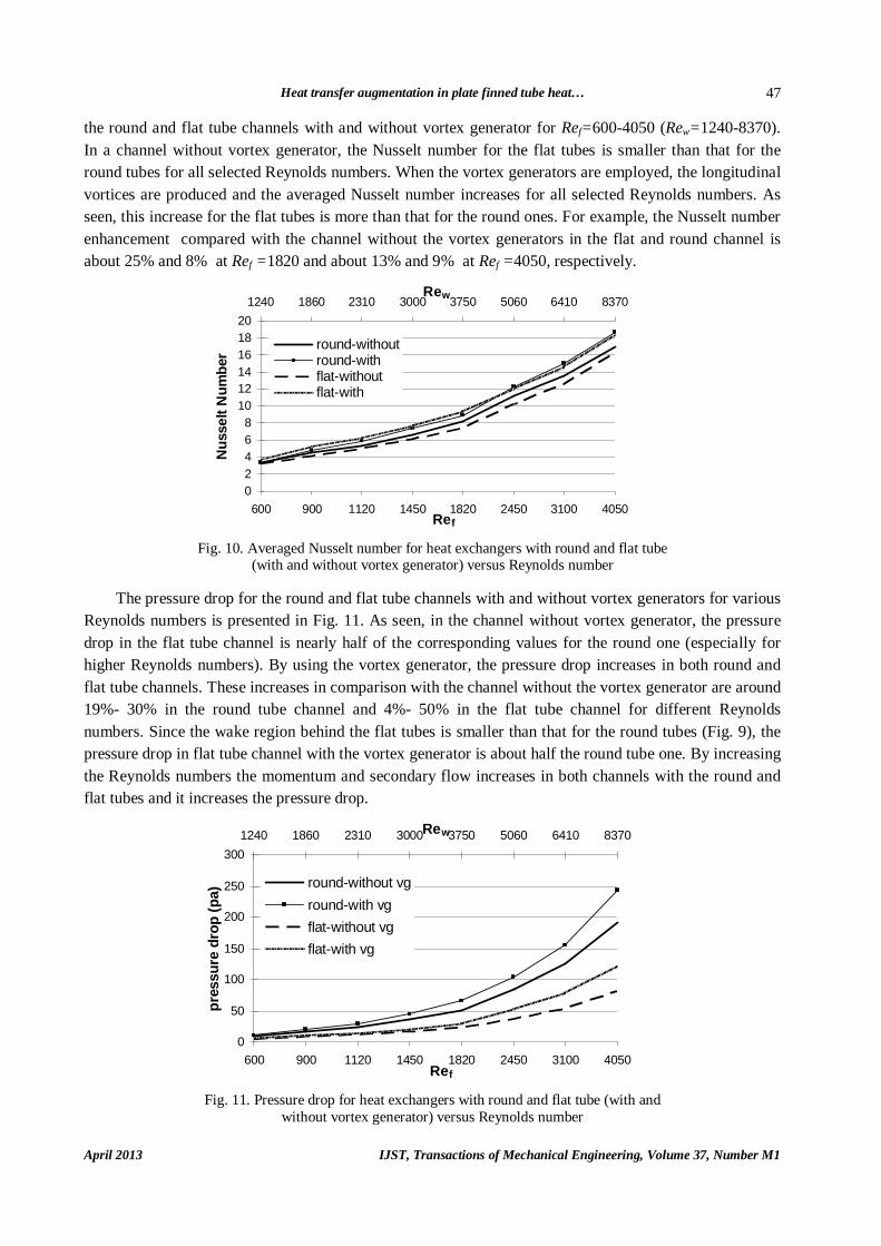
the round and flat tube channels with and without vortex generator for Ref=600-4050 (Rew=1240-8370). In a channel without vortex generator, the Nusselt number for the flat tubes is smaller than that for the round tubes for all selected Reynolds numbers. When the vortex generators are employed, the longitudinal vortices are produced and the averaged Nusselt number increases for all selected Reynolds numbers. As seen, this increase for the flat tubes is more than that for the round ones. For example, the Nusselt number enhancement compared with the channel without the vortex generators in the flat and round channel is about 25% and 8% at Ref =1820 and about 13% and 9% at Ref =4050, respectively.
02468
101214161820
600 900 1120 1450 1820 2450 3100 4050Ref
Nus
selt
Num
ber
1240 1860 2310 3000 3750 5060 6410 8370Rew
round-withoutround-withflat-without flat-with
Fig. 10. Averaged Nusselt number for heat exchangers with round and flat tube
(with and without vortex generator) versus Reynolds number The pressure drop for the round and flat tube channels with and without vortex generators for various
Reynolds numbers is presented in Fig. 11. As seen, in the channel without vortex generator, the pressure drop in the flat tube channel is nearly half of the corresponding values for the round one (especially for higher Reynolds numbers). By using the vortex generator, the pressure drop increases in both round and flat tube channels. These increases in comparison with the channel without the vortex generator are around 19%- 30% in the round tube channel and 4%- 50% in the flat tube channel for different Reynolds numbers. Since the wake region behind the flat tubes is smaller than that for the round tubes (Fig. 9), the pressure drop in flat tube channel with the vortex generator is about half the round tube one. By increasing the Reynolds numbers the momentum and secondary flow increases in both channels with the round and flat tubes and it increases the pressure drop.
0
50
100
150
200
250
300
600 900 1120 1450 1820 2450 3100 4050Ref
pres
sure
dro
p (p
a)
1240 1860 2310 3000 3750 5060 6410 8370Rew
round-without vground-with vgflat-without vgflat-with vg
Fig. 11. Pressure drop for heat exchangers with round and flat tube (with and
without vortex generator) versus Reynolds number
M. Mirzaei and A. Sohankar
IJST, Transactions of Mechanical Engineering, Volume 37, Number M1 April 2013
48
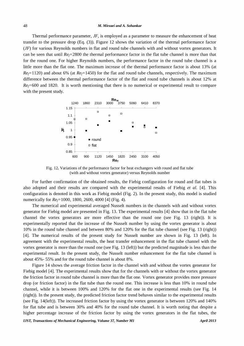
Thermal performance parameter, JF, is employed as a parameter to measure the enhancement of heat transfer to the pressure drop (Eq. (3)). Figure 12 shows the variation of the thermal performance factor (JF) for various Reynolds numbers in flat and round tube channels with and without vortex generators. It can be seen that until Ref=2800 the thermal performance factor in the flat tube channel is more than that for the round one. For higher Reynolds numbers, the performance factor in the round tube channel is a little more than the flat one. The maximum increase of the thermal performance factor is about 13% (at Ref=1120) and about 6% (at Ref=1450) for the flat and round tube channels, respectively. The maximum difference between the thermal performance factor of the flat and round tube channels is about 12% at Ref=600 and 1820. It is worth mentioning that there is no numerical or experimental result to compare with the present study.
0.85
0.9
0.95
1
1.05
1.1
1.15
600 900 1120 1450 1820 2450 3100 4050Ref
JF
1240 1860 2310 3000 3750 5060 6410 8370Rew
roundflat
Fig. 12. Variations of the performance factor for heat exchangers with round and flat tube
(with and without vortex generator) versus Reynolds number For further confirmation of the obtained results, the Fiebig configuration for round and flat tubes is
also adopted and their results are compared with the experimental results of Fiebig et al. [4]. This configuration is denoted in this work as Fiebig model (Fig. 2). In the present study, this model is studied numerically for Ref=1000, 1800, 2600, 4000 [4] (Fig. 4).
The numerical and experimental averaged Nusselt numbers in the channels with and without vortex generator for Fiebig model are presented in Fig. 13. The experimental results [4] show that in the flat tube channel the vortex generators are more effective than the round one (see Fig. 13 (right)). It is experimentally reported that the increase of the Nusselt number by using the vortex generator is about 10% in the round tube channel and between 80% and 120% for the flat tube channel (see Fig. 13 (right)) [4]. The numerical results of the present study for Nusselt number are shown in Fig. 13 (left). In agreement with the experimental results, the heat transfer enhancement in the flat tube channel with the vortex generator is more than the round one (see Fig. 13 (left)) but the predicted magnitude is less than the experimental result. In the present study, the Nusselt number enhancement for the flat tube channel is about 45%- 55% and for the round tube channel is about 8%.
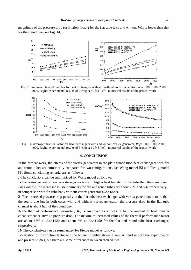
Figure 14 shows the average friction factor in the channel with and without the vortex generator for Fiebig model [4]. The experimental results show that for the channels with or without the vortex generator the friction factor in round tube channel is more than the flat one. Vortex generator provides more pressure drop (or friction factor) in the flat tube than the round one. This increase is less than 10% in round tube channel, while it is between 100% and 120% for the flat one in the experimental results (see Fig. 14 (right)). In the present study, the predicted friction factor trend behaves similar to the experimental results (see Fig. 14(left)). The increased friction factor by using the vortex generator is between 120% and 140% for flat tube and is between 30% and 40% for the round tube channel. It is worth noting that despite a higher percentage increase of the friction factor by using the vortex generators in the flat tubes, the
Heat transfer augmentation in plate finned tube heat…
April 2013 IJST, Transactions of Mechanical Engineering, Volume 37, Number M1
49
magnitude of the pressure drop (or friction factor) for the flat tube with and without VGs is lower than that for the round one (see Fig. 14).
Fig. 13. Averaged Nusselt number for heat exchangers with and without vortex generator, Ref=1000, 1800, 2600,
4000. Right: experimental results of Fiebig et al. [4], Left: numerical results of the present work
1030507090
110130150170190210
400 800 1200 1600 2000 2400 2800 3200 3600 4000
Re
1000f
flat-with vgflat-without vground-with vground-without vg
Fig. 14. Averaged friction factor for heat exchangers with and without vortex generator, Ref=1000, 1800, 2600,
4000. Right: experimental results of Fiebig et al. [4], Left: numerical results of the present work
4. CONCLUSION In the present work, the effects of the vortex generators in the plate finned tube heat exchangers with flat and round tubes are numerically compared for two configurations, i.e. Wang model [5] and Fiebig model [4]. Some concluding remarks are as follows: I-The conclusions can be summarized for Wang model as follows. 1-The vortex generator creates a stronger vortex with higher heat transfer for flat tube than the round one. For example, the increased Nusselt numbers for flat and round tubes are about 25% and 8%, respectively, in comparison with fin-tube bank without vortex generator (Ref=1820). 2- The increased pressure drop penalty in the flat-tube heat exchanger with vortex generators is more than the round one but in both cases with and without vortex generator, the pressure drop in the flat tube channel is about half of the round one. 3-The thermal performance parameter, JF, is employed as a measure for the amount of heat transfer enhancement relative to pressure drop. The maximum increased values of the thermal performance factor are about 13% at Ref=1120 and about 6% at Ref=1450 for the flat and round tube heat exchanger, respectively. II- The conclusions can be summarized for Fiebig model as follows: 1-Variation of the friction factor and the Nusselt number shows a similar trend in both the experimental and present studies, but there are some differences between their values.

M. Mirzaei and A. Sohankar
IJST, Transactions of Mechanical Engineering, Volume 37, Number M1 April 2013
50
2-The Nusselt number enhancement in the heat exchanger with VGs for the flat tubes is between 80% and 120% for experimental study [4], while they are between 45% and 55% in the present study. The aforementioned values for round tube are 10% and 8% for the experimental study [4] and the present work, respectively. 3- The heat exchanger with round tubes and VGs gives nearly twice as much pressure loss as the corresponding heat exchanger with round tubes for both numerical and experimental [4] studies. The aforementioned ratio is about four for heat exchanger without VGs.
In general, the flat tube with VGs provides better thermal performance than the round one, especially at the lower Reynolds number. Of course, the performance of a plate finned tube heat exchanger depends on geometrical parameters such as the tubes form (round or flat tube), tubes arrangement (inline or staggered), and tubes and fins spacing and relative position of VGs in the channel. The differences between the predicted results for the two selected configurations (Wang model [5] and Fiebig model [4]) are due to some of the aforementioned parameters.
In this study, some discrepancies are observed between the experimental and numerical results while their variations occur in similar manner. Wang et al. [5] also compared their numerical and experimental results and a discrepancy of more than 30% was reported. Using different grids, turbulence models and neglecting the unsteadiness by employing the steady solution are a number of reasons for such discrepancies. It should be noted that flow over bluff bodies such as tubes and vortex generators often contains many complex phenomena such as separation, wake flow, vortex shedding, curved free shear layers, dominant large scale structures and high turbulence. Since most of these phenomena such as vortex shedding are inherently unsteady, employing the steady computations can produce results with larger discrepancy in comparison to experimental ones.
REFERENCES 1. Shah, R. K. & Sekulic, D. P. (2003). Fundamentals of heat exchangers design. John and Wiley & Sons. 2. Torri, K., Kwak, K. & Nishino, K. (2002). Heat transfer enhancement accompanying pressure-loss reduction
with winglet-type vortex generators for fin tube heat exchangers. Int. J. Heat and Mass Transfer., Vol. 45, pp. 3795-3801.
3. Torri, K., Kwak, K. & Nishino, K. (2006). Simultaneous heat transfer enhancement and pressure loss reduction for finned-tube bundles with the first or two transverse row of built-in winglets. Int. J. Experimental Thermal and Fluid Science, Vol. 29, pp. 625-632.
4. Fiebig, M., Mitra, N. K. & Valencia, A. (1994). Local heat transfer and flow losses in fin-and-tube heat exchangers with vortex generators: A comparison of round and flat tubes. Int. J. Experimental Thermal and Fluid Science, Vol. 8, pp. 35-45.
5. Wang, L. B., Ke, F., Gao, S. D. & Mei, Y. G. (2001). Local and average characteristics of heat/mass transfer over flat tube bank fin with four vortex generators per tube. Int. J. Heat and Mass Transfer, Vol. 124, pp. 546-553.
6. Ke, F., Wang, L. B., Hua, L., Gao, S. D. & Su, Y. X. (2006). The optimum angle of attack of delta winglet vortex generators on heat transfer performance of finned flat tube bank with considering nonuniform fin temperature. Int. J. Experimental Heat Transfer, Vol. 19, pp. 227–249.
7. Wang, L. B., Liang, H., Zhang, Y. H., Zhu, C. L. & Sun, D. L. Numerical study of interactions of vortices generated by vortex generators and their effects on heat transfer enhancement. Int. J. Numerical Heat Transfer, part A, Vol. 50, pp. 353-368.
8. Chang, L. M., Wang, L. B., Song, K. W., Sun, D. L. & Fan, J. F. (2009). Numerical study of the relationship between heat transfer enhancement and absolute vorticity flux along main flow direction in a channel formed by a flat tube bank fin with vortex generators. Int. J. Heat and Mass Transfer, Vol. 5, pp. 1794-1801.

Heat transfer augmentation in plate finned tube heat…
April 2013 IJST, Transactions of Mechanical Engineering, Volume 37, Number M1
51
9. Sohankar, A. & Davidson, L. (2001). Effect of inclined vortex generators on heat transfer enhancement in a three-dimensional channel. Numerical Heat Transfer, Vol. 39, Part A, pp. 433–448.
10. Sohankar, A. (2004). The LES and DNS simulations of heat transfer and fluid flow in a plate-fin heat exchanger with vortex generators. Iranian Journal of Science & Technology, Transaction B: Engineering, Vol. 28, No. B4.
11. Sohankar, A. (2007). Heat transfer augmentation in a rectangular channel with a vee-shaped vortex generator. Int. J. Heat and fluid flow, Vol. 28, pp. 306–317.
12. Mahmood, G. I., Ligrani, P. M. & Chen, K. (2003). Variable property and temperature ratio effects on Nusselt numbers in a rectangular channel with 45 angled rib turbulators. Journal of Heat Transfer ASME, Vol. 125, pp. 769–778.


