Embed Size (px)
Citation preview
Sep. 24, 2009
Heat Pump Technology Development in Japan
Naoki ShikazonoDepartment of Mechanical Engineering
Collaborative Research Center for Energy Engineering (CEE)The University of Tokyo
[email protected]://www.feslab.t.u-tokyo.ac.jp/index.html
Sep. 24, 2009
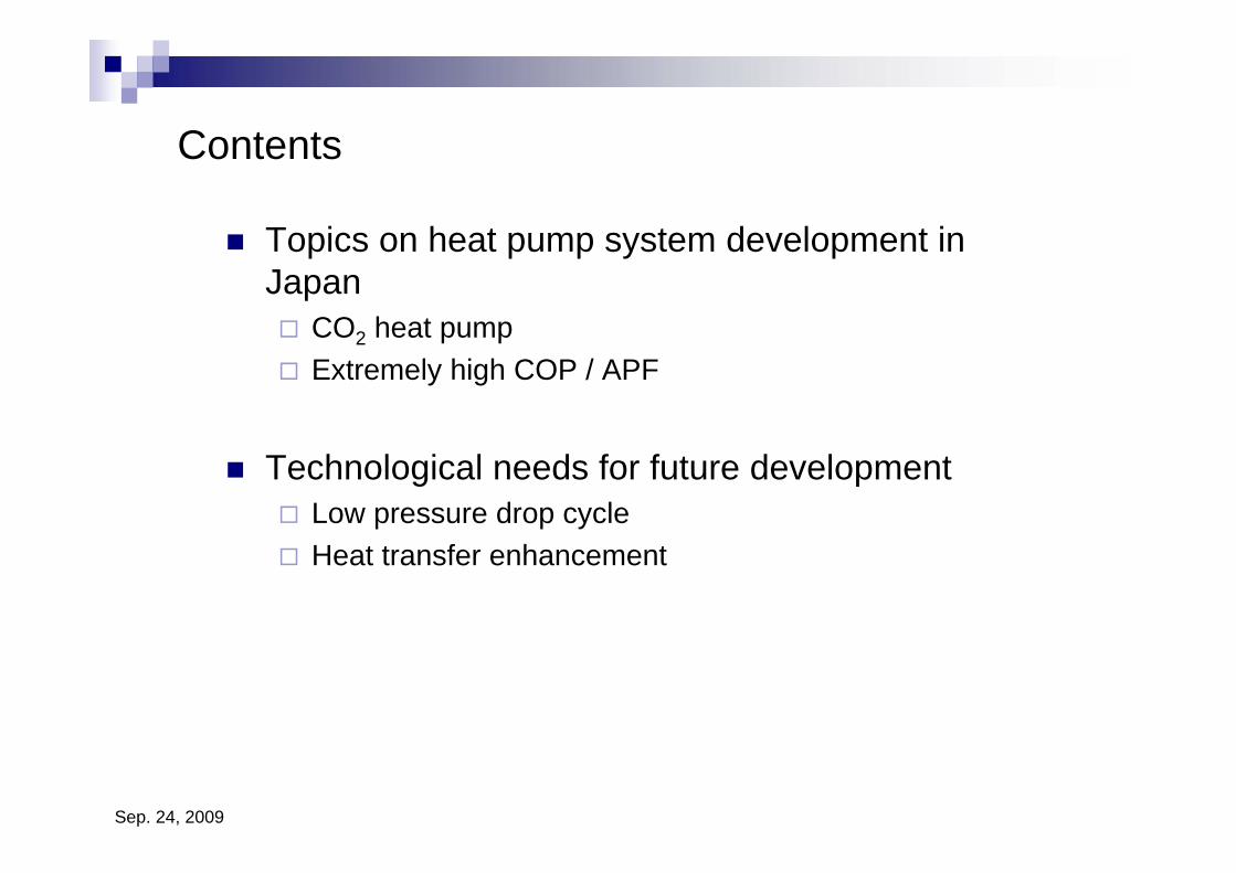
Contents
Topics on heat pump system development in Japan
CO2 heat pumpExtremely high COP / APF
Technological needs for future developmentLow pressure drop cycleHeat transfer enhancement
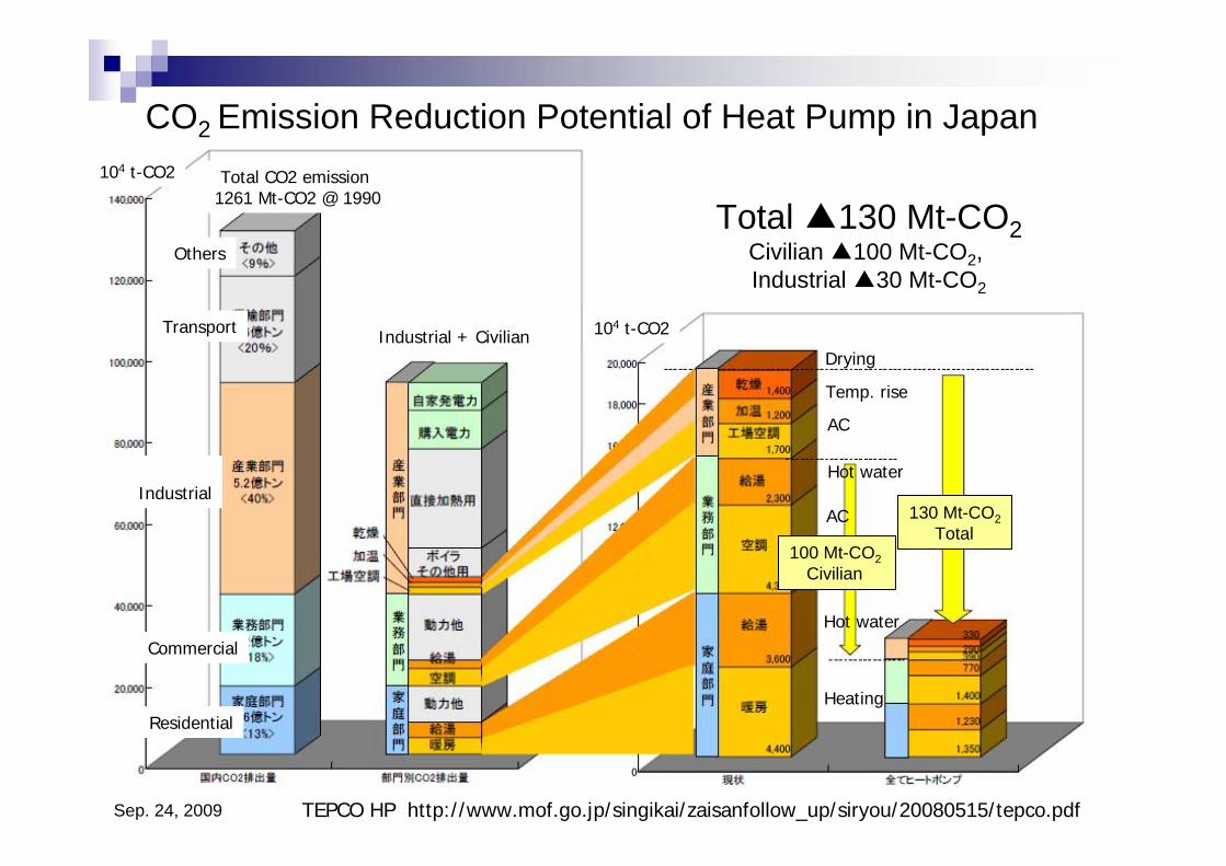
Sep. 24, 2009 TEPCO HP http://www.mof.go.jp/singikai/zaisanfollow_up/siryou/20080515/tepco.pdf
CO2 Emission Reduction Potential of Heat Pump in Japan
Drying
Temp. rise
AC
Hot water
AC
Hot water
Heating
Commercial
Total ▲130 Mt-CO2Civilian ▲100 Mt-CO2, Industrial ▲30 Mt-CO2
100 Mt-CO2 Civilian
130 Mt-CO2Total
Total CO2 emission 1261 Mt-CO2 @ 1990
Industrial + Civilian
Residential
Industrial
Transport
Others
104 t-CO2
104 t-CO2
Sep. 24, 2009
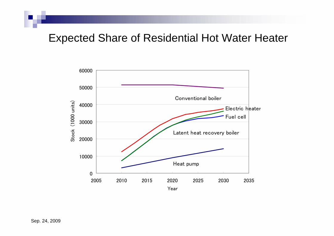
Expected Share of Residential Hot Water Heater
0
10000
20000
30000
40000
50000
60000
2005 2010 2015 2020 2025 2030 2035
Year
Sto
ck
(1000 u
nits)
Heat pump
Latent heat recovery boiler
Fuel cell
Electric heater
Conventional boiler
Sep. 24, 2009
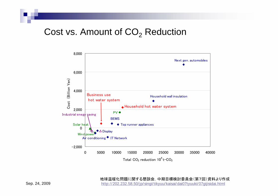
Cost vs. Amount of CO2 Reduction
地球温暖化問題に関する懇談会,中期目標検討委員会(第7回)資料より作成http://202.232.58.50/jp/singi/tikyuu/kaisai/dai07tyuuki/07gijisidai.html
-2,000
0
2,000
4,000
6,000
8,000
0 5000 10000 15000 20000 25000 30000 35000 40000
Total CO2 reduction 104 t-CO2
Cos
t (B
illion Y
en)
Wind power
PV
Air conditioning
Business use hot water system
Household hot water system
Solar heat
IT Network
Household wall insulation
Display
Top runner appliances
Next gen. automobiles
Industrial enegy savingBEMS
Sep. 24, 2009
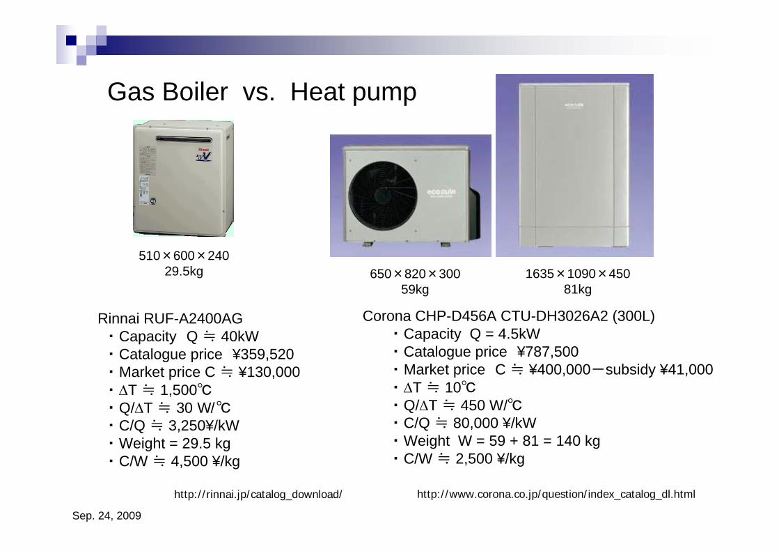
Gas Boiler vs. Heat pump
Corona CHP-D456A CTU-DH3026A2 (300L)・ Capacity Q = 4.5kW・ Catalogue price ¥787,500・ Market price C ≒ ¥400,000-subsidy ¥41,000・ ΔT ≒ 10℃・ Q/ΔT ≒ 450 W/℃・ C/Q ≒ 80,000 ¥/kW ・ Weight W = 59 + 81 = 140 kg・ C/W ≒ 2,500 ¥/kg
Rinnai RUF-A2400AG・ Capacity Q ≒ 40kW・ Catalogue price ¥359,520・ Market price C ≒ ¥130,000・ ΔT ≒ 1,500℃・ Q/ΔT ≒ 30 W/℃・ C/Q ≒ 3,250¥/kW・ Weight = 29.5 kg・ C/W ≒ 4,500 ¥/kg
650×820×30059kg
1635×1090×45081kg
510×600×24029.5kg
http://www.corona.co.jp/question/index_catalog_dl.htmlhttp://rinnai.jp/catalog_download/
Sep. 24, 2009
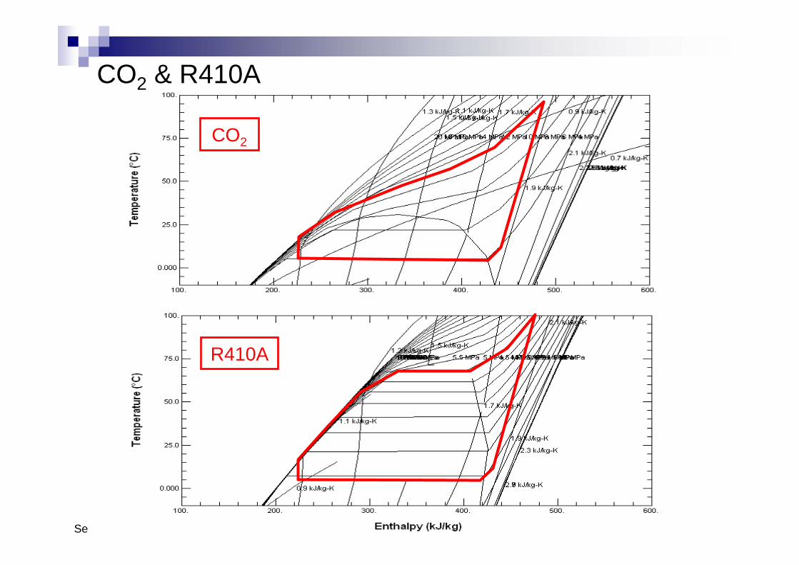
CO2 & R410A
CO2
R410A
Sep. 24, 2009
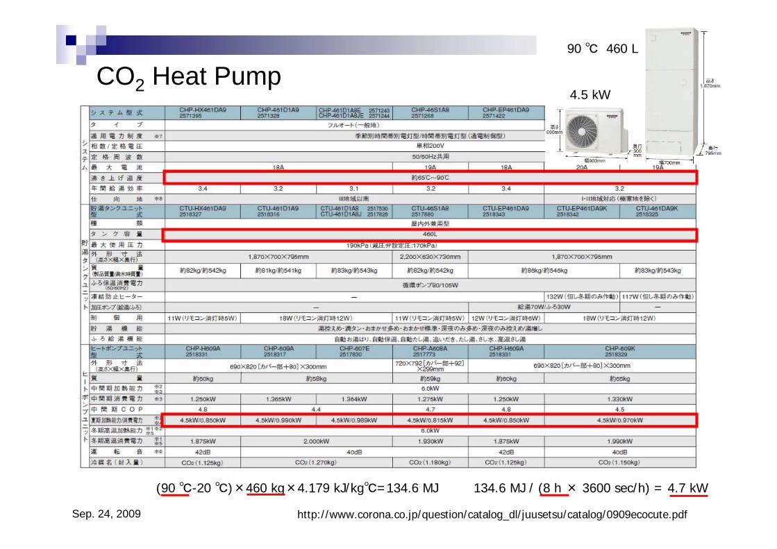
CO2 Heat Pump
(90 ℃-20 ℃)×460 kg×4.179 kJ/kg℃=134.6 MJ 134.6 MJ / (8 h × 3600 sec/h) = 4.7 kW
90 ℃ 460 L
4.5 kW
http://www.corona.co.jp/question/catalog_dl/juusetsu/catalog/0909ecocute.pdf
Sep. 24, 2009
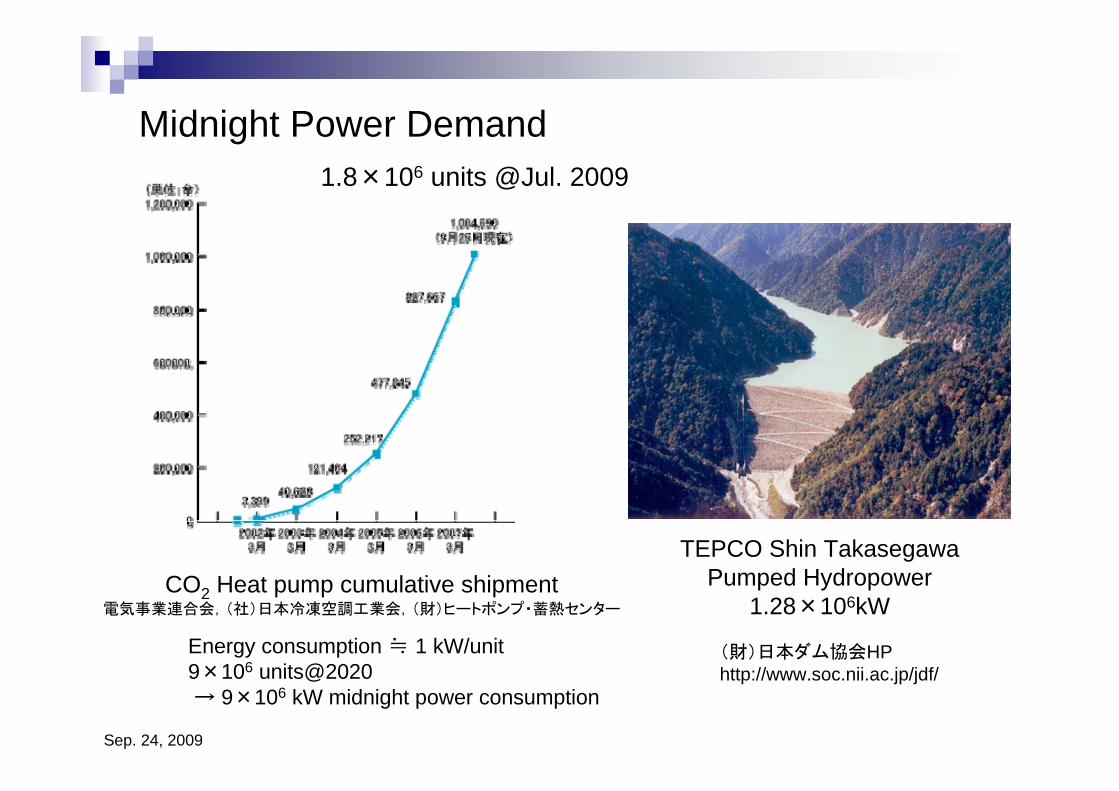
Midnight Power Demand
CO2 Heat pump cumulative shipment電気事業連合会,(社)日本冷凍空調工業会,(財)ヒートポンプ・蓄熱センター
TEPCO Shin TakasegawaPumped Hydropower
1.28×10⁶kW
(財)日本ダム協会HPhttp://www.soc.nii.ac.jp/jdf/
1.8×10⁶ units @Jul. 2009
Energy consumption ≒ 1 kW/unit9×106 units@2020 → 9×10⁶ kW midnight power consumption
Sep. 24, 2009
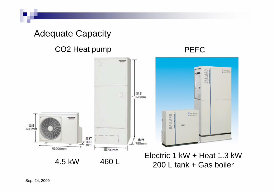
Adequate Capacity
Electric 1 kW + Heat 1.3 kW200 L tank + Gas boiler4.5 kW 460 L
PEFCCO2 Heat pump
Sep. 24, 2009
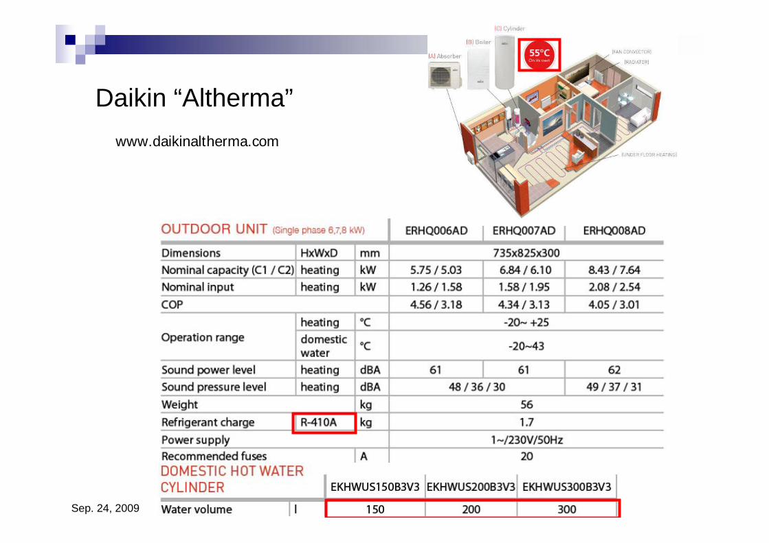
Daikin “Altherma”www.daikinaltherma.com
Sep. 24, 2009
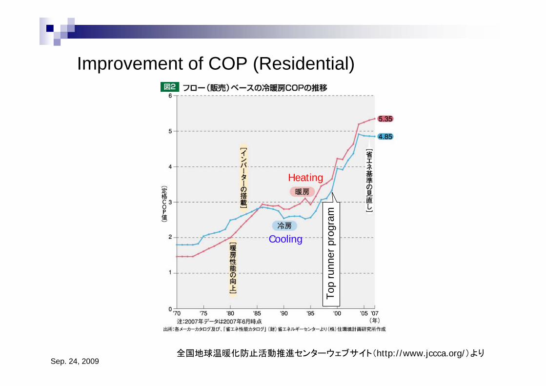
Improvement of COP (Residential)
全国地球温暖化防止活動推進センターウェブサイト(http://www.jccca.org/)より
Heating
Cooling
Top
runn
er p
rogr
am
Sep. 24, 2009
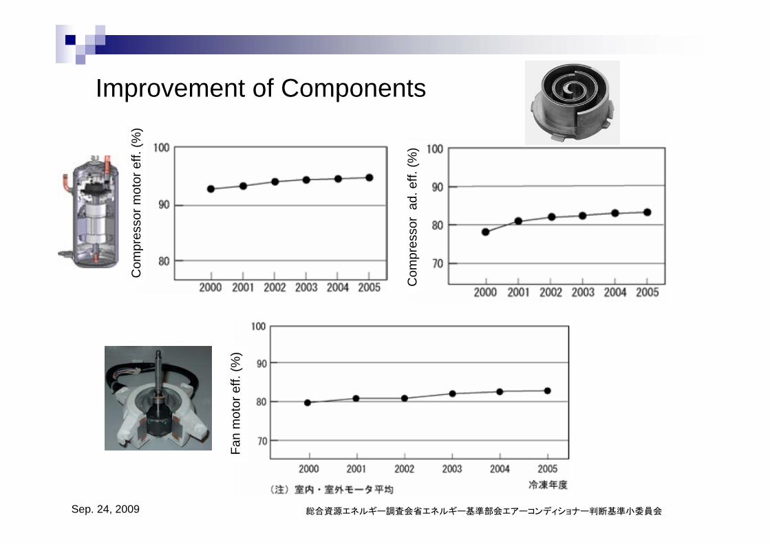
Improvement of Components
Com
pres
sor m
otor
eff.
(%)
Com
pres
sor
ad. e
ff. (%
)
Fan
mot
or e
ff. (%
)
総合資源エネルギー調査会省エネルギー基準部会エアーコンディショナー判断基準小委員会
Sep. 24, 2009
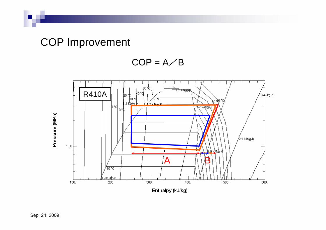
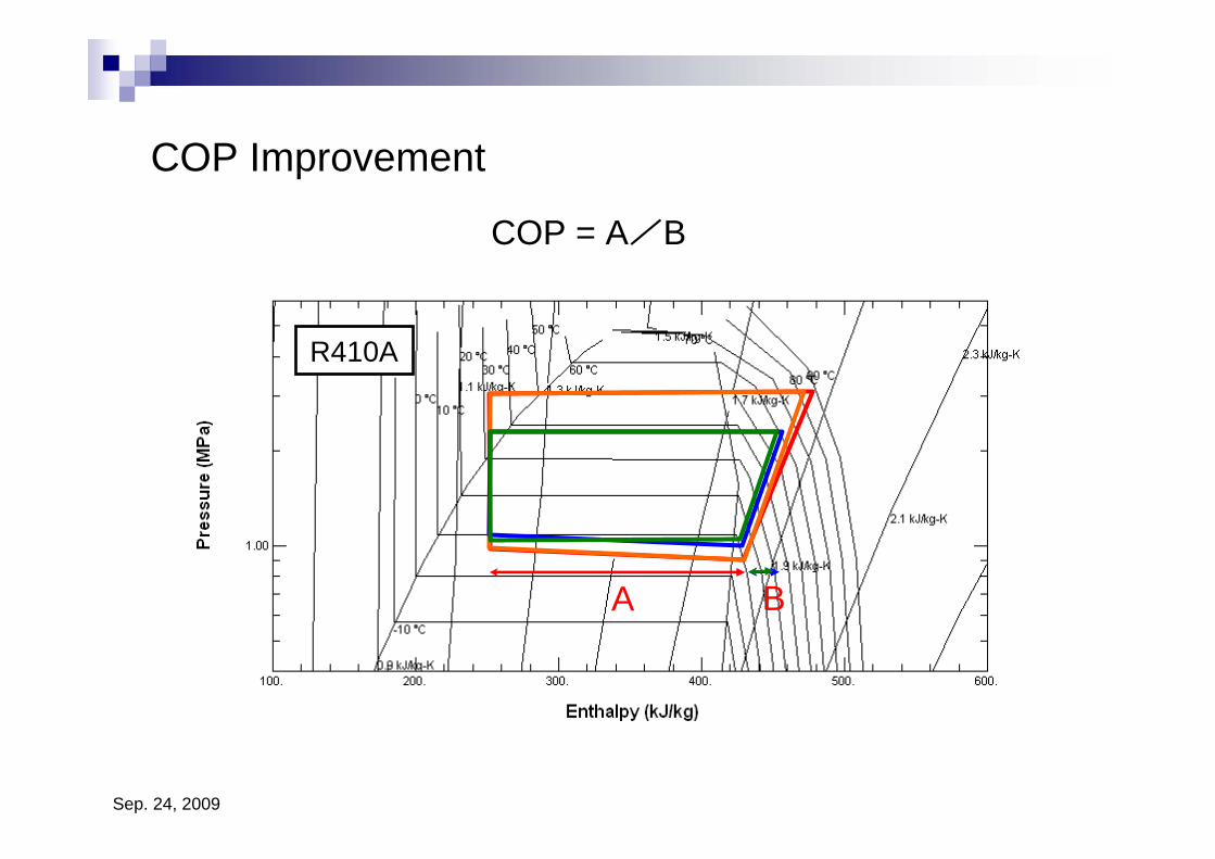
COP Improvement
R410A
A B
COP = A/B
Sep. 24, 2009
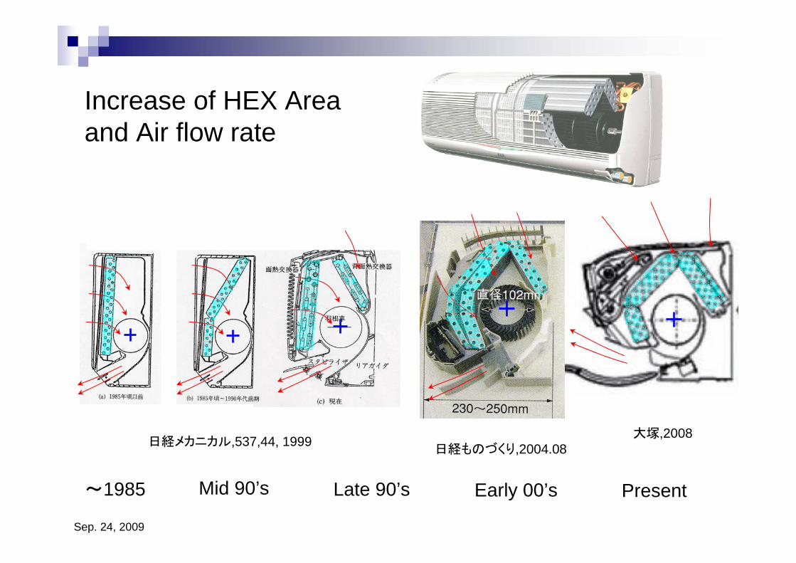
Increase of HEX Area and Air flow rate
~1985 Mid 90’s Late 90’s Present
日経ものづくり,2004.08日経メカニカル,537,44, 1999
Early 00’s
大塚,2008
Sep. 24, 2009
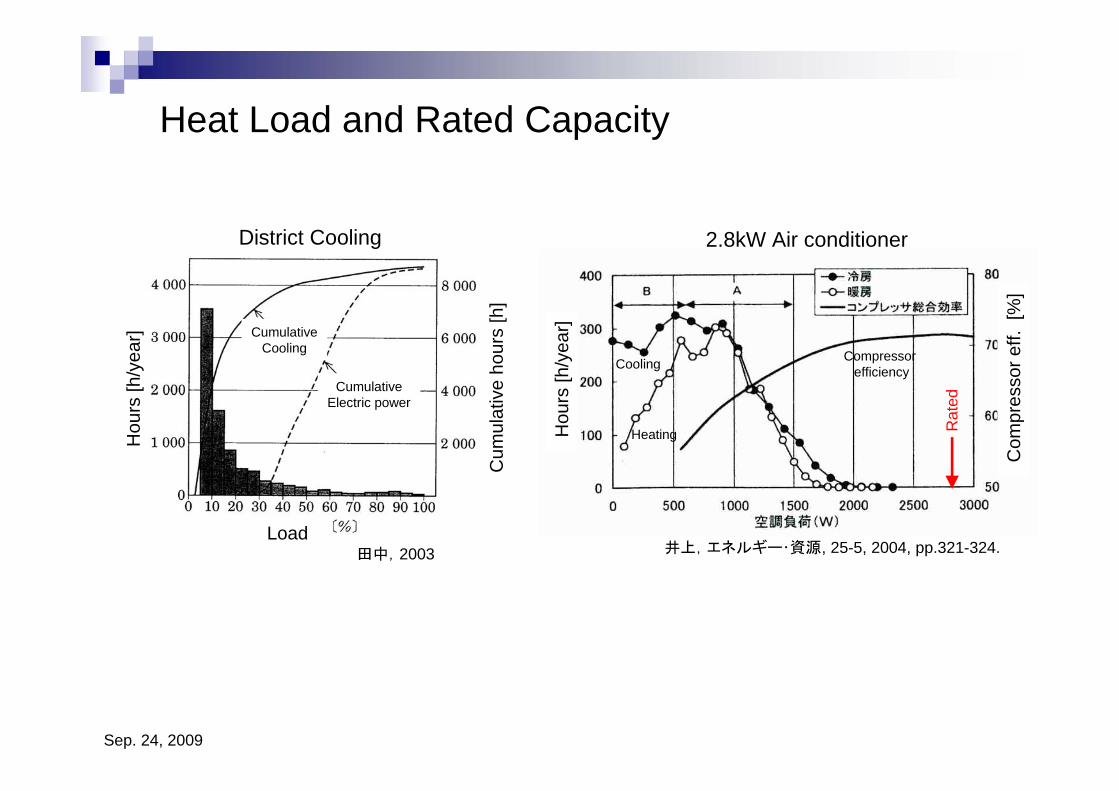
Heat Load and Rated Capacity
2.8kW Air conditionerDistrict Cooling
田中,2003 井上,エネルギー・資源, 25-5, 2004, pp.321-324.
Rat
ed
Load
Hou
rs [h
/yea
r]
Cum
ulat
ive
hour
s [h
]
CumulativeCooling
CumulativeElectric power
Hou
rs [h
/yea
r]
Heating
Cooling
Com
pres
sor e
ff. [
%]
Compressor efficiency
Sep. 24, 2009
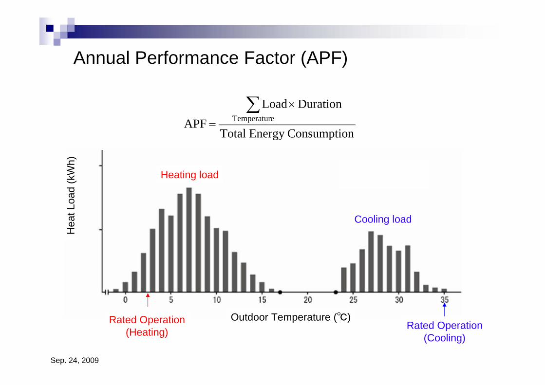
Hea
t Loa
d (k
Wh)
Outdoor Temperature (℃)
Heating load
Cooling load
nConsumptioEnergyTotal
DurationLoadAPF eTemperatur
∑ ×
=
Rated Operation(Heating) Rated Operation
(Cooling)
Annual Performance Factor (APF)
Sep. 24, 2009
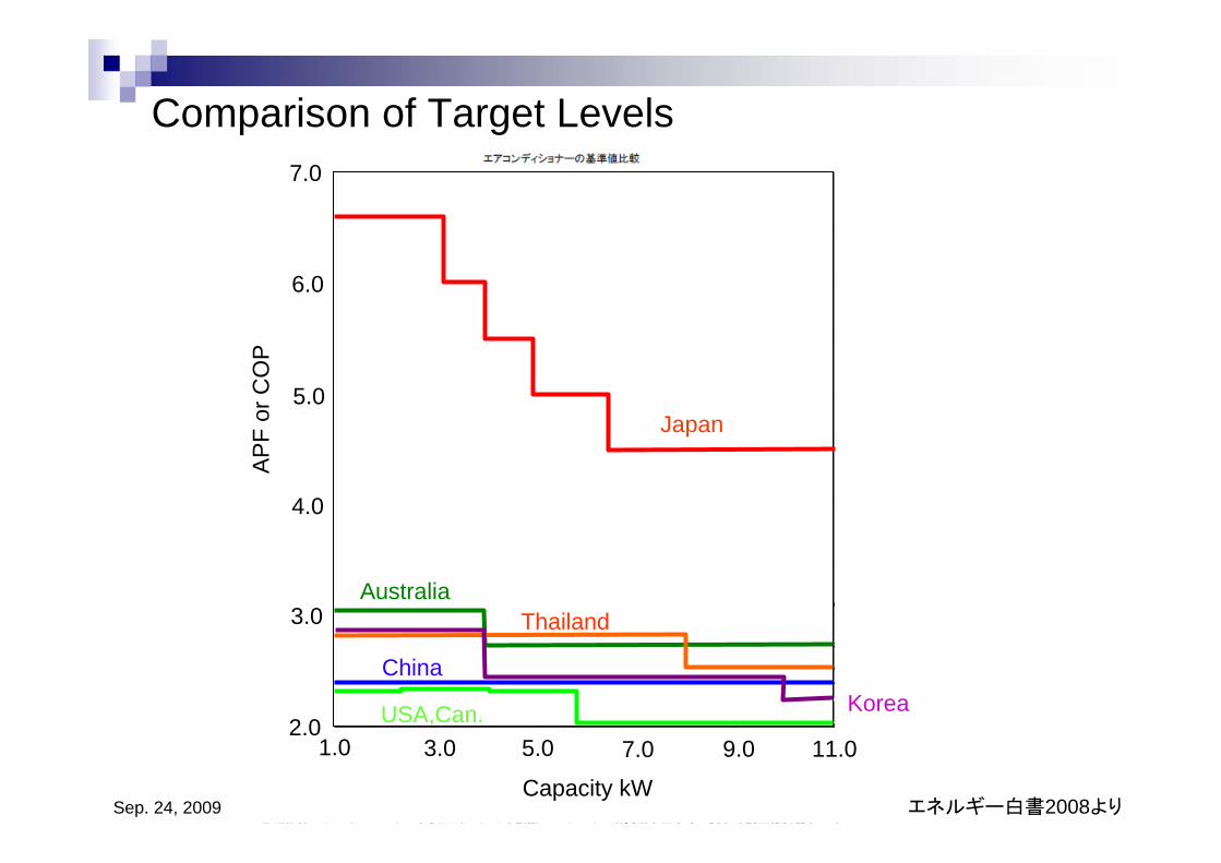
Comparison of Target Levels
エネルギー白書2008より
Australia
China
Thailand
USA,Can. Korea
Japan
3.0 5.0 7.0 9.0 11.0
Capacity kW
2.0
3.0
4.0
5.0
6.0
7.0
1.0
AP
F or
CO
P
Sep. 24, 2009
COP Improvement
R410A
A B
COP = A/B
Sep. 24, 2009
冷房運転時圧力測定点
凝縮器
膨張弁
液
室外機
ガス
圧
室内機
サービスバルブ
P1
P2
接続配管
5m
調整絞
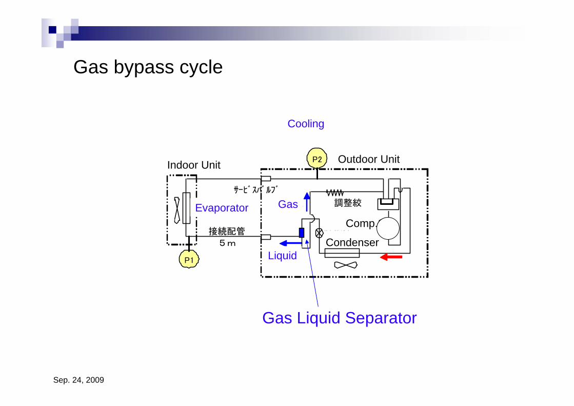
Gas bypass cycle
Indoor Unit Outdoor Unit
Cooling
Evaporator
Condenser
Comp.
Liquid
Gas
Gas Liquid Separator
Sep. 24, 2009
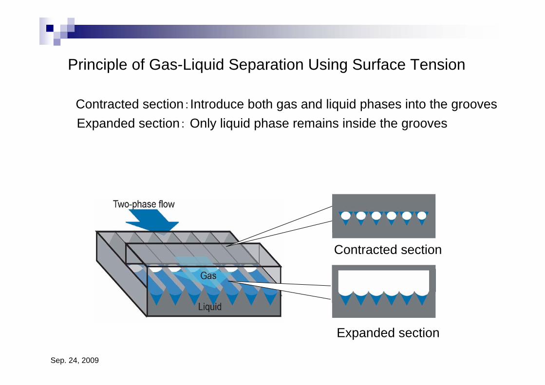
Principle of Gas-Liquid Separation Using Surface Tension
Contracted section
Expanded section
Expanded section: Only liquid phase remains inside the grooves Contracted section:Introduce both gas and liquid phases into the grooves
Sep. 24, 2009
0.0
0.2
0.4
0.6
0.8
1.0
1.2
1.4
1.6
1.8
0 10 20 30 40 50 60
Gas Weber number Weg
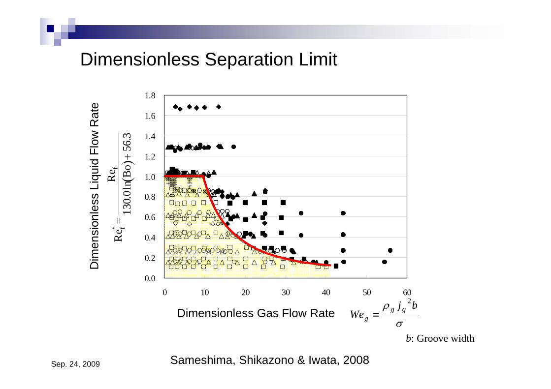
Dimensionless Separation Limit
Re f*
=R
e f13
0.0l
nBo (
)+56
.3
Dim
ensi
onle
ss L
iqui
d Fl
ow R
ate
Dimensionless Gas Flow Rateσ
ρ bjWe gg
g
2
≡
b: Groove width
Sameshima, Shikazono & Iwata, 2008
Sep. 24, 2009
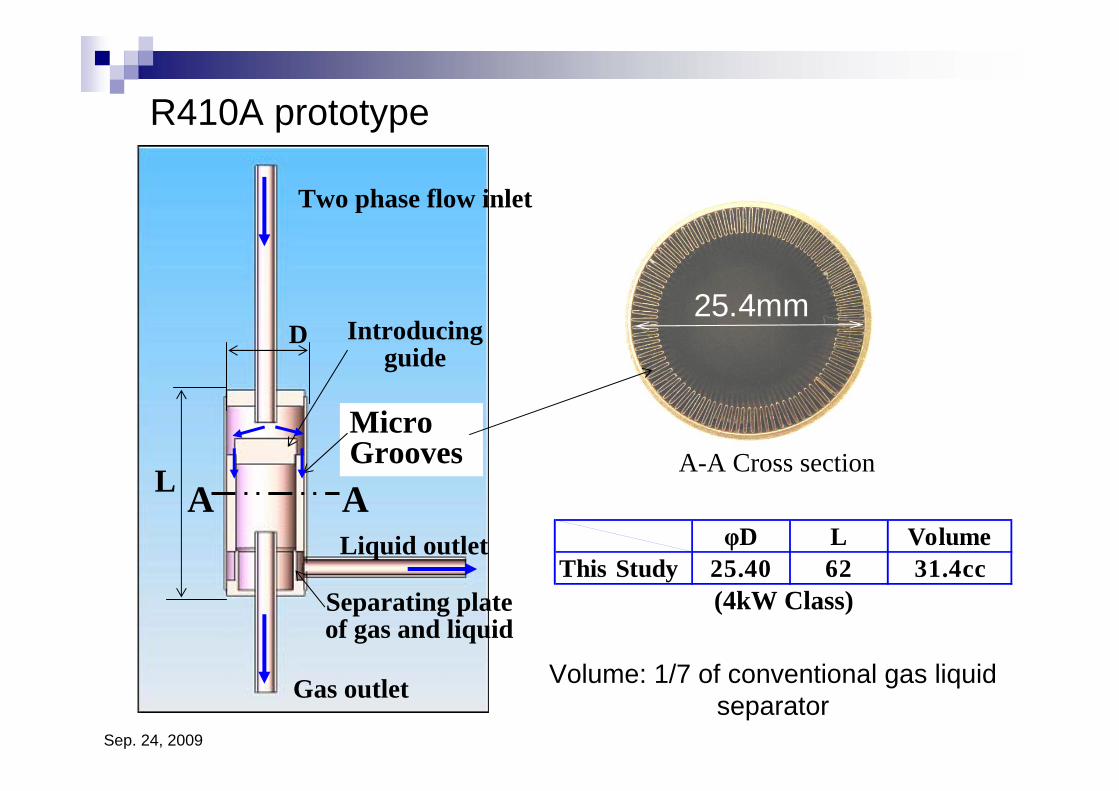
R410A prototype
Two phase flow inlet
D Introducingguide
MicroGrooves
Liquid outlet
L
Separating plateof gas and liquid
Gas outlet
A AA-A Cross section
(4kW Class)
φD L VolumeThis Study 25.40 62 31.4cc
Volume: 1/7 of conventional gas liquid separator
25.4mm
Sep. 24, 2009
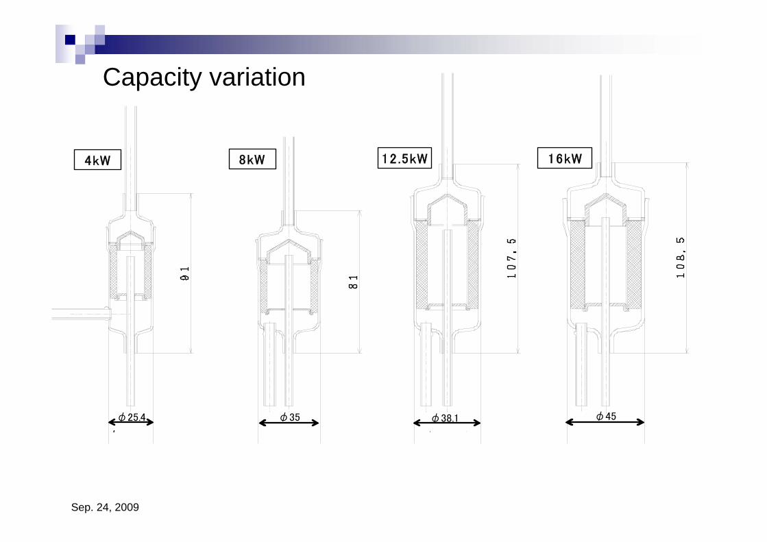
φ45φ38.1φ35φ25.4
4kW 8kW 12.5kW 16kW
Capacity variation
Sep. 24, 2009
0.0
0.5
1.0
1.5
2.0
10 20 30 40 50 60 70 80 90 100 110Flow Rate G (kg/s)
gL/G
L(%
)
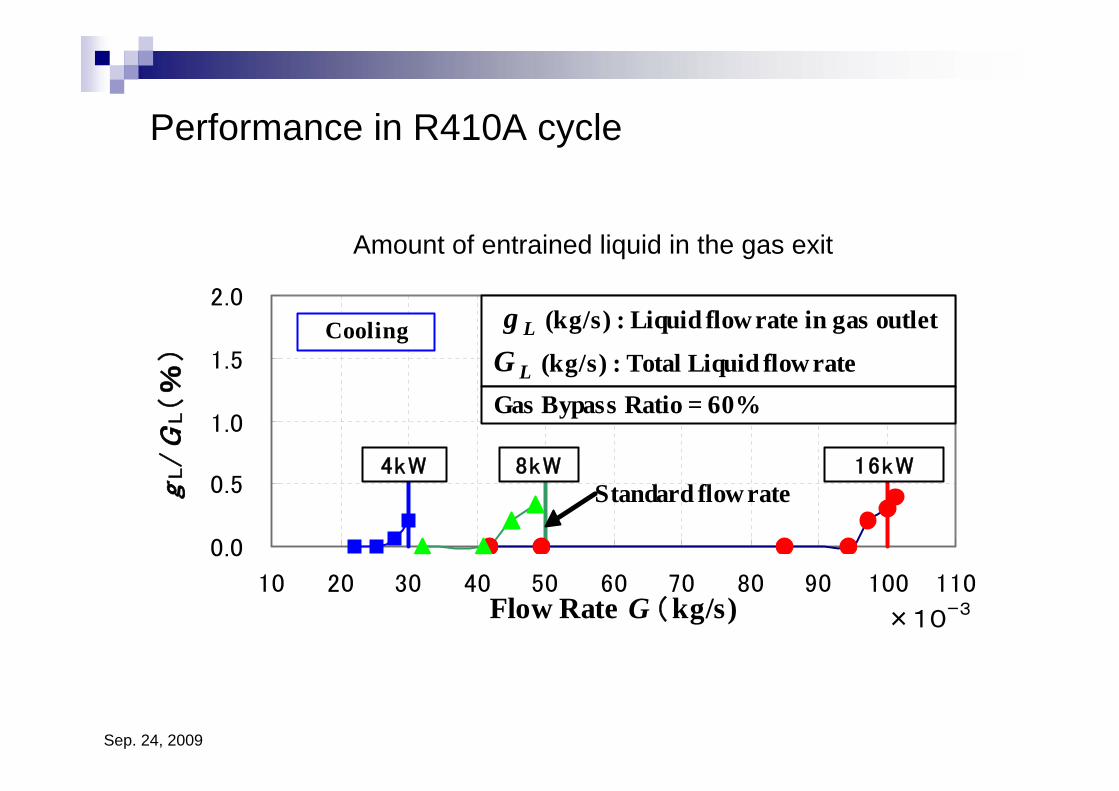
16kW8kW4kW
Cooling g L (kg/s) : Liquid flow rate in gas outlet
G L (kg/s) : Total Liquid flow rate
×10ー3
Gas Bypass Ratio = 60%
Standard flow rate
Performance in R410A cycle
Amount of entrained liquid in the gas exit
Sep. 24, 2009
冷房運転時圧力測定点
凝縮器
膨張弁
液
室外機
ガス
圧
室内機
サービスバルブ
P1
P2
接続配管
5m
調整絞
0
0.1
0.2
0.3
0.4
20 25 30 35
室内機吸込空気温度(℃)
低圧
側圧
力損
失(M
Pa)
前歴(気液分離器無)
気液分離器付き
圧力損失低減効果
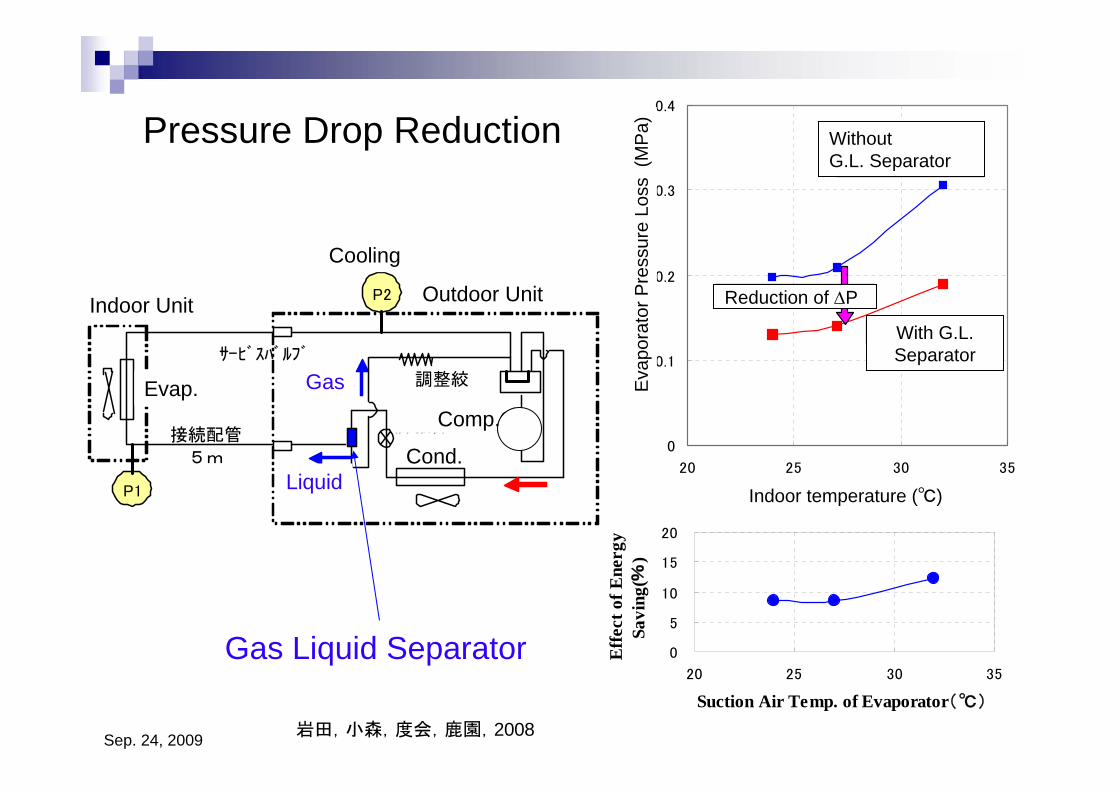
Pressure Drop Reduction
Indoor Unit Outdoor Unit
Cooling
Evap.
Cond.
Comp.
Liquid
Gas
0
5
10
15
20
20 25 30 35
Suction Air Temp. of Evaporator(℃)
Eff
ect o
f Ene
rgy
Savi
ng(%
)
Indoor temperature (℃)
Eva
pora
tor P
ress
ure
Loss
(M
Pa) Without
G.L. Separator
With G.L. Separator
Reduction of ΔP
Gas Liquid Separator
岩田,小森,度会,鹿園,2008
Sep. 24, 2009
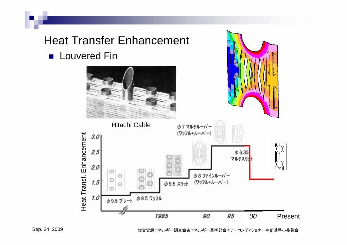
Heat Transfer Enhancement
総合資源エネルギー調査会省エネルギー基準部会エアーコンディショナー判断基準小委員会
Hea
t Tra
nsf.
Enh
ance
men
t
Louvered Fin
Hitachi Cable
00 Present
Sep. 24, 2009
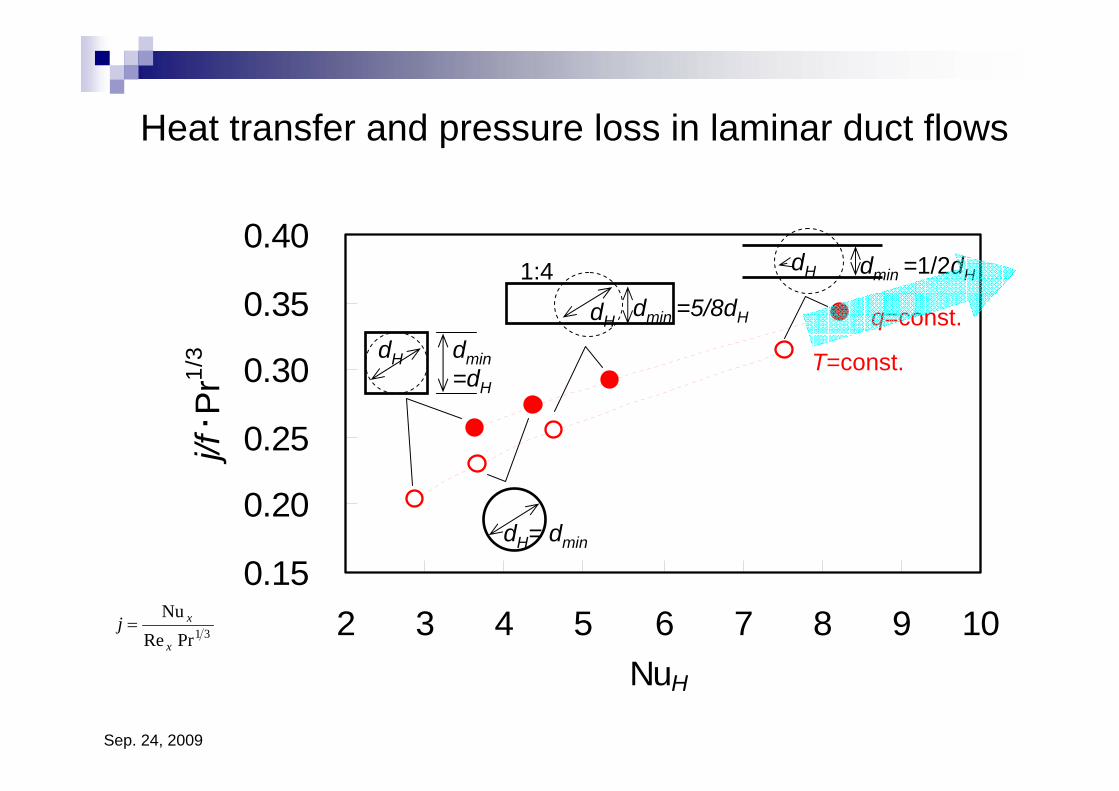
Heat transfer and pressure loss in laminar duct flows
0.15
0.20
0.25
0.30
0.35
0.40
2 3 4 5 6 7 8 9 10NuH
j/f・ P
r1/3 dmin
=dH
dH
dH dmin =1/2dH
dmin =5/8dHdH
1:4
dH= dmin
q=const.
T=const.
31PrReNu
x
xj =
Sep. 24, 2009
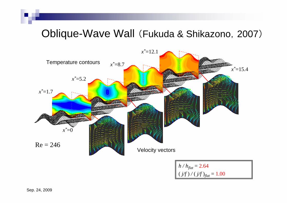
Oblique-Wave Wall (Fukuda & Shikazono,2007)
x*=1.7
x*=5.2
x*=8.7
x*=12.1
x*=0
x*=15.4
h / hflat = 2.64( j/f ) / ( j/f )flat = 1.00
Re = 246Velocity vectors
Temperature contours
Sep. 24, 2009
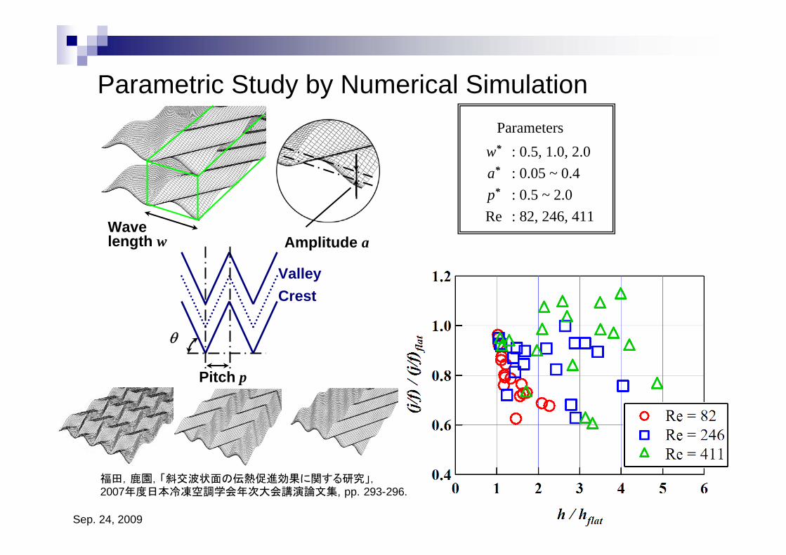
w*
a*
p*
Re
: 0.5, 1.0, 2.0: 0.05 ~ 0.4: 0.5 ~ 2.0: 82, 246, 411
Parameters
福田,鹿園,「斜交波状面の伝熱促進効果に関する研究」,2007年度日本冷凍空調学会年次大会講演論文集, pp. 293-296.
Wave length w
Pitch p
Amplitude a
θ
CrestValley
Parametric Study by Numerical Simulation
Sep. 24, 2009
Summary
Heat pump products in Japan CO2 heat pumpExtremely high COP & APF
Low cost technology required without degrading COP
Low pressure loss cycleHeat transfer enhancement without pressure loss penalty・・・