Embed Size (px)
Citation preview
Heads II
Inductive and AMR Head
T. Stobiecki
6 wykład 8.11.2004
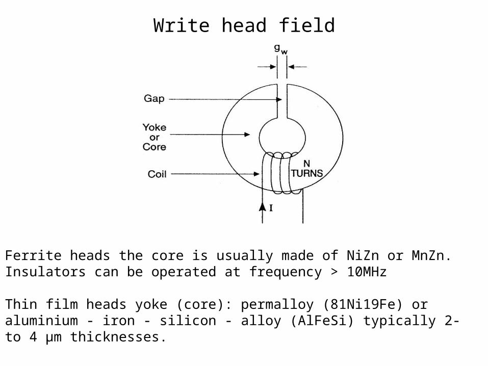
Write head field
Ferrite heads the core is usually made of NiZn or MnZn.Insulators can be operated at frequency > 10MHz
Thin film heads yoke (core): permalloy (81Ni19Fe) or aluminium - iron - silicon - alloy (AlFeSi) typically 2- to 4 µm thicknesses.
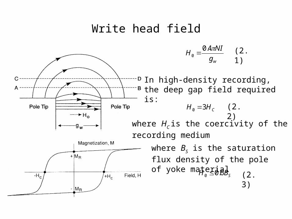
Write head field
wg
NIH
4.00
CHH 30
SBH 6.00
In high-density recording, the deep gap field required is:
where HC is the coercivity of the recording
medium
where BS is the saturation flux density
of the pole of yoke material
(2.1)
(2.2)
(2.3)
4
222
10
w
wX g
yx
ygtan
HH
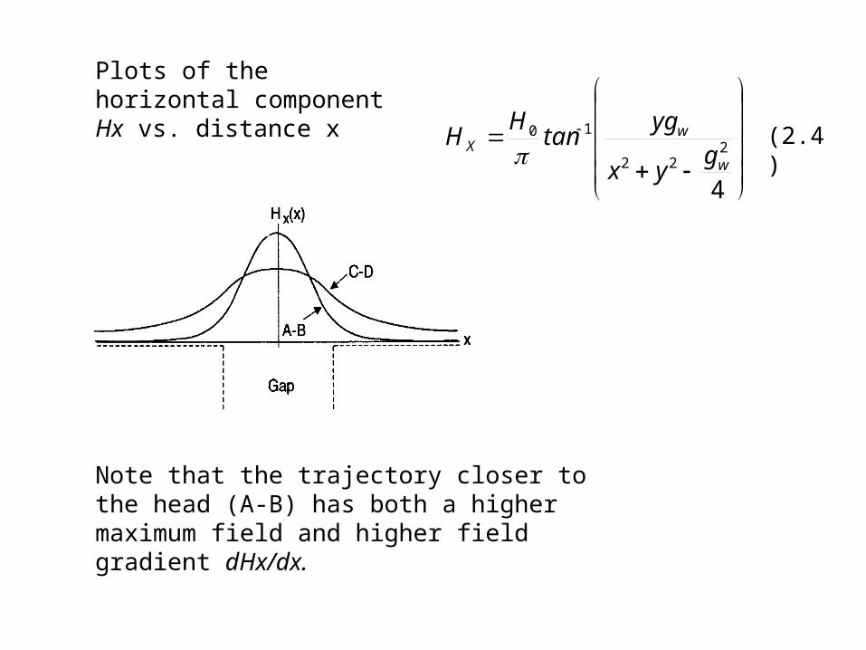
Plots of the horizontal component Hx vs. distance x
Note that the trajectory closer to the head (A-B) has both a higher maximum field and higher field gradient dHx/dx.
(2.4)
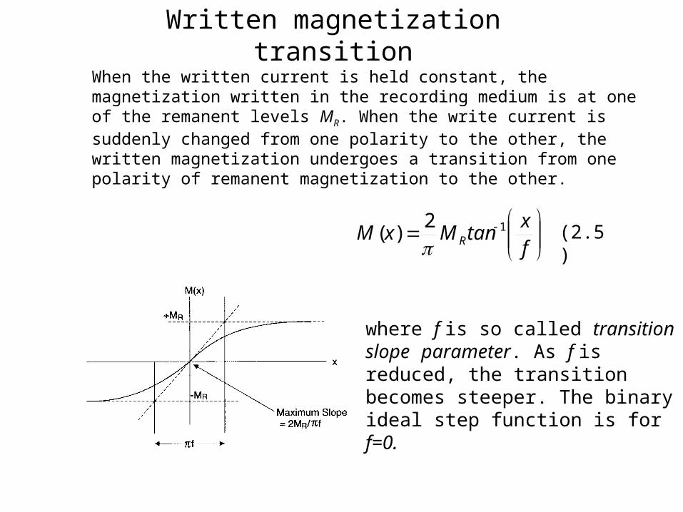
Written magnetization transition
When the written current is held constant, the magnetization written in the recording medium is at one of the remanent levels MR. When the write current is suddenly changed from one polarity to the other, the written magnetization undergoes a transition from one polarity of remanent magnetization to the other.
fx
tanMxM R12
)(
(2.5)
where f is so called transition slope parameter. As f is reduced, the transition becomes steeper. The binary ideal step function is for f=0.
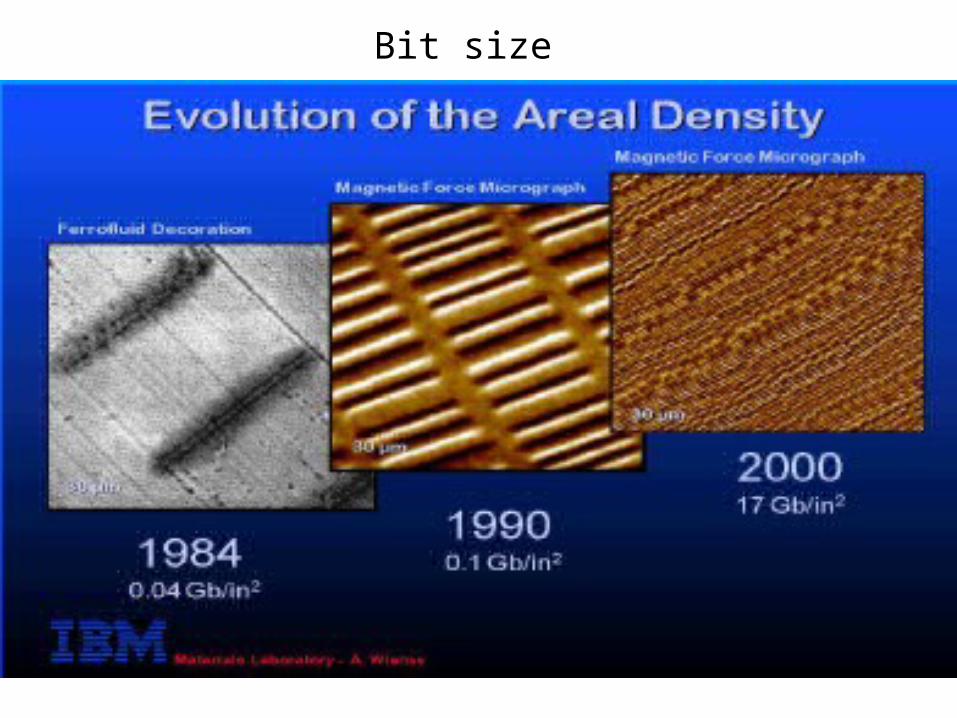
Bit size
Written magnetization transition
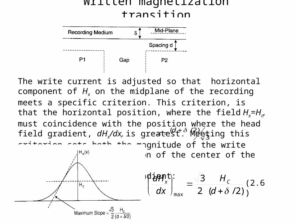
The write current is adjusted so that horizontal component of Hx on the midplane of the recording meets a specific criterion. This criterion, is that the horizontal position, where the field Hx=Hc, must coincidence with the position where the head field gradient, dHx/dx, is greatest. Meeting this criterion sets both the magnitude of the write current Iw and the x position of the center of the magnetization transition: The maximum head field gradient:
)2/(23
max
d
H
dx
dH Cx
3)2/( dx
(2.6)
Written magnetization transition
2max
4
f
M
dx
dH Rd
dx
HHd
dHdM
dxdM demaghead
2
1
2/3
22
d
M
Hf
R
C
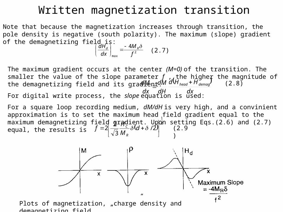
Note that because the magnetization increases through transition, the pole density is negative (south polarity). The maximum (slope) gradient of the demagnetizing field is:
(2.7)
The maximum gradient occurs at the center (M=0) of the transition. The smaller the value of the slope parameter f , the higher the magnitude of the demagnetizing field and its gradient.
For digital write process, the slope equation is used:
For a square loop recording medium, dM/dH is very high, and a convinient approximation is to set the maximum head field gradient equal to the maximum demagnetizing field gradient. Upon setting Eqs.(2.6) and (2.7) equal, the results is
(2.8)
(2.9)
Plots of magnetization, „charge”density and demagnetizing field
Written magnetization transition
fx
tanMxM R12
)(
2
1
2/3
22
d
M
Hf
R
C
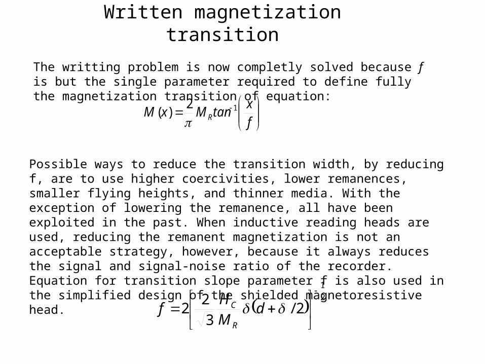
The writting problem is now completly solved because f is but the single parameter required to define fully the magnetization transition of equation:
Possible ways to reduce the transition width, by reducing f, are to use higher coercivities, lower remanences, smaller flying heights, and thinner media. With the exception of lowering the remanence, all have been exploited in the past. When inductive reading heads are used, reducing the remanent magnetization is not an acceptable strategy, however, because it always reduces the signal and signal-noise ratio of the recorder.Equation for transition slope parameter f is also used in the simplified design of the shielded magnetoresistive head.
Recording medium, fringing fields
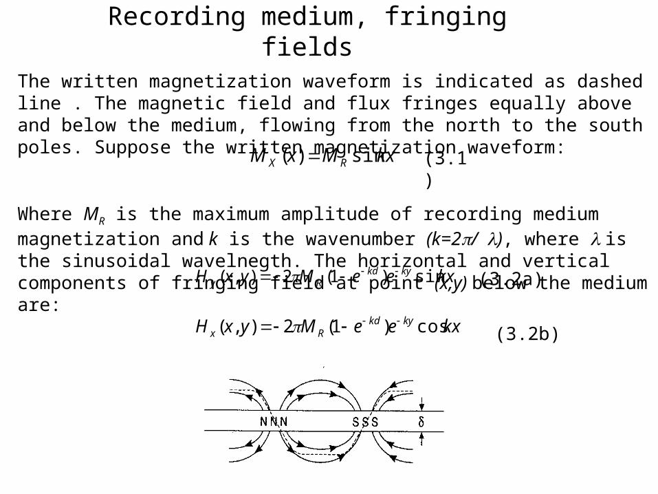
The written magnetization waveform is indicated as dashed line . The magnetic field and flux fringes equally above and below the medium, flowing from the north to the south poles. Suppose the written magnetization waveform:
Where MR is the maximum amplitude of recording medium magnetization and k is the wavenumber (k=2/), where is the sinusoidal wavelnegth. The horizontal and vertical components of fringing field at point (x,y) below the medium are:
kxMxM RX sin)(
kxeeMyxH kykdRy sin)1(2),(
kxeeMyxH kykdRx cos)1(2),(
(3.1)
(3.2a)
(3.2b)
Read-head flux
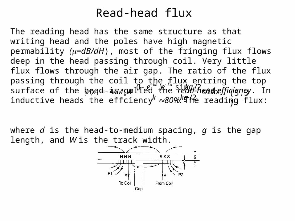
The reading head has the same structure as that writing head and the poles have high magnetic permability (=dB/dH), most of the fringing flux flows deep in the head passing through coil. Very little flux flows through the air gap. The ratio of the flux passing through the coil to the flux entring the top surface of the head is called the read-head efficiency. In inductive heads the effciency 80%. The reading flux:
where d is the head-to-medium spacing, g is the gap length, and W is the track width.
kxkg
kg
k
eeWMx
kdk
R sin2/
2/sin)1(4)(
(3.3)
Output voltage
dx
dNV
dt
dN
dt
NdE
888 1010)(
10
kxkg
kgeeMNVWxE kdk
R cos2/
2/sin)1(410)( 8
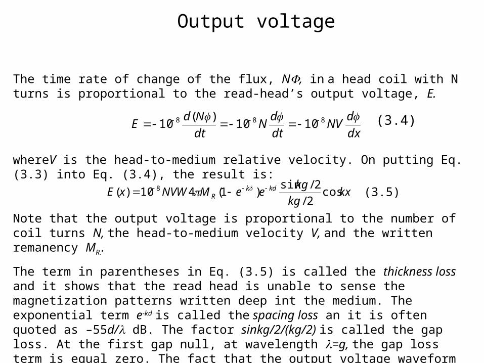
The time rate of change of the flux, N, in a head coil with N turns is proportional to the read-head’s output voltage, E.
whereV is the head-to-medium relative velocity. On putting Eq.(3.3) into Eq. (3.4), the result is:
Note that the output voltage is proportional to the number of coil turns N, the head-to-medium velocity V, and the written remanency MR..
The term in parentheses in Eq. (3.5) is called the thickness loss and it shows that the read head is unable to sense the magnetization patterns written deep int the medium. The exponential term e-kd is called the spacing loss an it is often quoted as –55d/ dB. The factor sinkg/2/(kg/2) is called the gap loss. At the first gap null, at wavelength =g, the gap loss term is equal zero. The fact that the output voltage waveform is a cosine when a sine wave is written shows that the phase of the output signal is lagging 90o behind the written magnetization.
(3.4)
(3.5)
Output spectrum
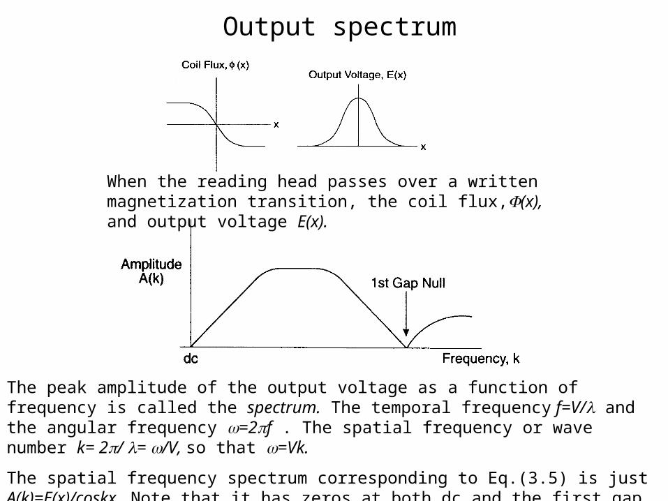
When the reading head passes over a written magnetization transition, the coil flux,(x), and output voltage E(x).
The peak amplitude of the output voltage as a function of frequency is called the spectrum. The temporal frequency f=V/ and the angular frequency =2f . The spatial frequency or wave number k= 2/ = /V, so that =Vk.
The spatial frequency spectrum corresponding to Eq.(3.5) is just A(k)=E(x)/coskx. Note that it has zeros at both dc and the first gap null = g.
AMR- Anisotropic magnetoreistance effect
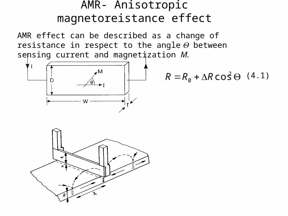
20 cosRRR
AMR effect can be described as a change of resistance in respect to the angle between sensing current and magnetization M.
(4.1)
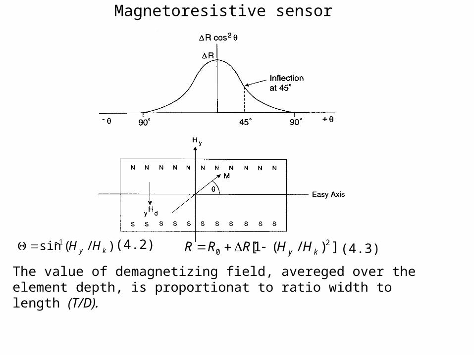
Magnetoresistive sensor
)/(sin 1ky HH ])/(1[ 2
0 ky HHRRR
The value of demagnetizing field, avereged over the element depth, is proportionat to ratio width to length (T/D).
(4.2) (4.3)
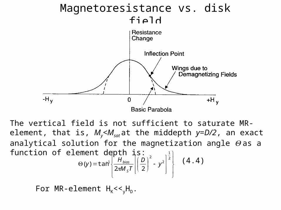
Magnetoresistance vs. disk field
The vertical field is not sufficient to saturate MR-element, that is, My<Msat at the middepth y=D/2, an exact analytical solution for the magnetization angle as a function of element depth is:
(4.4)
2
1
22
1
22tan)( y
D
TM
Hy
S
bias
For MR-element HK<<yHD.
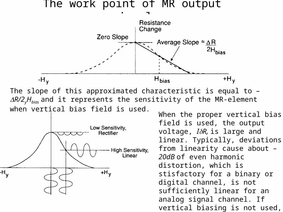
The work point of MR output signal
The slope of this approximated characteristic is equal to –R/2yHbias and it represents the sensitivity of the MR-element when vertical bias field is used.
When the proper vertical bias field is used, the output voltage, IR, is large and linear. Typically, deviations from linearity cause about – 20dB of even harmonic distortion, which is stisfactory for a binary or digital channel, is not sufficiently linear for an analog signal channel. If vertical biasing is not used, the response is of low sensitivity and is highly nonlinear.
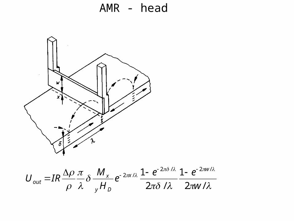
AMR - head
/2
1
/2
1 /2/2/2
w
eee
H
MIRU
wx
Dy
xout
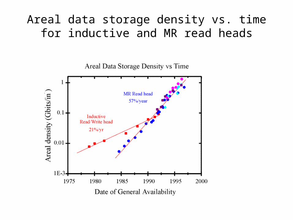
Areal data storage density vs. time for inductive and MR read heads
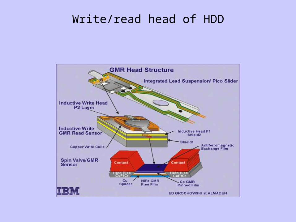
Write/read head of HDD