Embed Size (px)
Citation preview
®
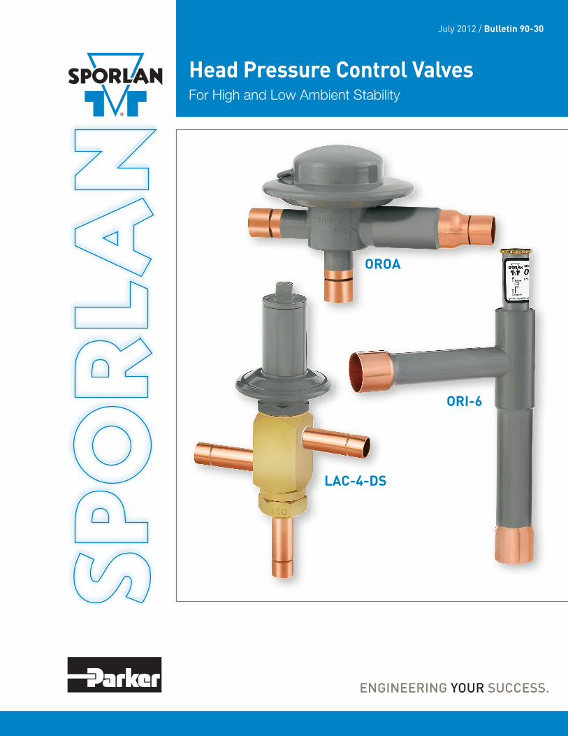
Head Pressure Control Valves For High and Low Ambient Stability
July 2012 / Bulletin 90-30
ORI-6
LAC-4-DS
OROA
Page 2 – Bulletin 90-30
⚠WARNING – USER RESPONSIBILITYFailure or improper selection or improper use of the products described herein or related items can cause death, personal injury and property damage.
This document and other information from Parker Hannifin Corporation, its subsidiaries and authorized distributors provide product or system options for further investigation by users having technical expertise.
The user, through its own analysis and testing, is solely responsible for making the final selection of the system and components and assuring that all performance, endurance, maintenance, safety and warning requirements of the application are met. The user must analyze all aspects of the application, follow applicable industry standards, and follow the information concerning the product in the current product catalog and in any other materials provided from Parker or its subsidiaries or authorized distributors.
To the extent that Parker or its subsidiaries or authorized distributors provide component or system options based upon data or specifications provided by the user, the user is responsible for determining that such data and specifications are suitable and sufficient for all applications and reasonably foreseeable uses of the components or systems.
For safety information see the Safety Guide at www.parker.com/safety or call 1-800-CParker.
The design of air conditioning and refrigeration systems utilizing air cooled condensing units involves two main problems that must be solved if the system is to operate reliably and economically. . . high ambient and low ambient operation. If the condensing unit is properly sized, it will operate satisfactorily during extremely high ambient temperatures. However, since most units will be required to operate at ambient temperatures below their design dry bulb temperature during most of the year, the solution to low ambient operation is more complex.
Without good head pressure control during low ambient operation, the system can experience both running cycle and off-cycle problems. Two running cycle problems are of prime concern:
1. Since the pressure differential across the thermostatic expansion valve port affects the rate of refrigerant flow, low head pressure generally causes insufficient refrig-erant to be fed to the evaporator.
2. Any system using hot gas for defrost or compressor capacity control must have a normal head pressure to operate properly. In either case failure to have sufficient head pressure will result in low suction pressure and/or iced evaporator coils.
The primary off-cycle problem is the possible inability to get the system on-line if the refrigerant has migrated to the condenser. The evaporator pressure may not build up to the cut-in point of the low pressure control and the compressor can’t start even though refrigeration is required. Even if the evaporator pressure builds up to the cut-in setting, insufficient flow through the TEV will cause a low suction pressure, which results in compressor cycling.
The typical method of maintaining normal head pressure in a refrigeration system during periods of low ambient temperature is to restrict liquid flow from the condenser to the receiver, and at the same time divert hot gas to the inlet of the receiver. This backs liquid refrigerant up into the condenser reducing its capacity which in turn increases the condensing pressure. At the same time the hot gas raises liquid pressure in the receiver, allowing the system to operate normally.
Sporlan has adjustable and fixed setting direct acting head pressure control valves for systems from 1 to 35 tons.
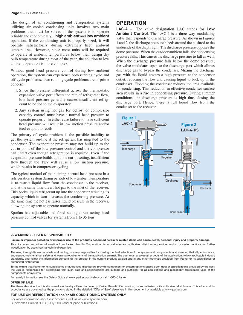
OPERATIONLAC-4 – The valve designation LAC stands for Low Ambient Control. The LAC-4 is a three way modulating valve that responds to discharge pressure. As shown in Figures 1 and 2, the discharge pressure bleeds around the pushrod to the underside of the diaphragm. The discharge pressure opposes the dome pressure. When the outdoor ambient falls, the condensing pressure falls. This causes the discharge pressure to fall as well. When the discharge pressure falls below the dome pressure, the valve modulates open to the discharge port which allows discharge gas to bypass the condenser. Mixing the discharge gas with the liquid creates a high pressure at the condenser outlet, reducing the flow and causing liquid to back up in the condenser. Flooding the condenser reduces the area available for condensing. This reduction in effective condenser surface area results in a rise in condensing pressure. During summer conditions, the discharge pressure is high thus closing the discharge port. Hence, there is full liquid flow from the condenser to the receiver.
Discharge
Receiver
CondenserDischarge
Receiver
Condenser
LAC-4
LAC-4-DS
Figure 1
Figure 2
OFFER OF SALEThe items described in this document are hereby offered for sale by Parker Hannifin Corporation, its subsidiaries or its authorized distributors. This offer and its acceptance are governed by the provisions stated in the detailed “Offer of Sale” elsewhere in this document or available at www.parker.com.
FOR USE ON REFRIGERATION and/or AIR CONDITIONING SYSTEMS ONLYFor more information about our products visit us at www.sporlan.com.Supersedes Bulletin 90-30, July 2006 and all prior publications.
Bulletin 90-30 – Page 3
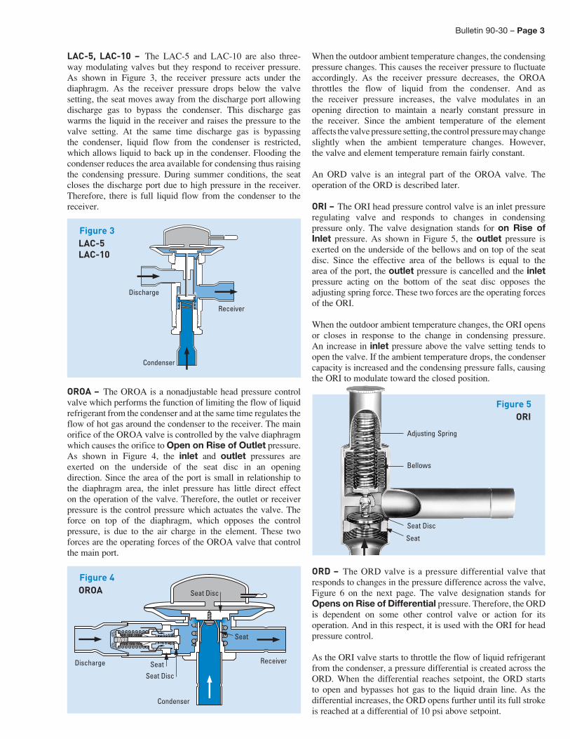
LAC-5, LAC-10 – The LAC-5 and LAC-10 are also three-way modulating valves but they respond to receiver pressure. As shown in Figure 3, the receiver pressure acts under the diaphragm. As the receiver pressure drops below the valve setting, the seat moves away from the discharge port allowing discharge gas to bypass the condenser. This discharge gas warms the liquid in the receiver and raises the pressure to the valve setting. At the same time discharge gas is bypassing the condenser, liquid flow from the condenser is restricted, which allows liquid to back up in the condenser. Flooding the condenser reduces the area available for condensing thus raising the condensing pressure. During summer conditions, the seat closes the discharge port due to high pressure in the receiver. Therefore, there is full liquid flow from the condenser to the receiver.
OROA – The OROA is a nonadjustable head pressure control valve which performs the function of limiting the flow of liquid refrigerant from the condenser and at the same time regulates the flow of hot gas around the condenser to the receiver. The main orifice of the OROA valve is controlled by the valve diaphragm which causes the orifice to Open on Rise of Outlet pressure. As shown in Figure 4, the inlet and outlet pressures are exerted on the underside of the seat disc in an opening direction. Since the area of the port is small in relationship to the diaphragm area, the inlet pressure has little direct effect on the operation of the valve. Therefore, the outlet or receiver pressure is the control pressure which actuates the valve. The force on top of the diaphragm, which opposes the control pressure, is due to the air charge in the element. These two forces are the operating forces of the OROA valve that control the main port.
When the outdoor ambient temperature changes, the condensing pressure changes. This causes the receiver pressure to fluctuate accordingly. As the receiver pressure decreases, the OROA throttles the flow of liquid from the condenser. And as the receiver pressure increases, the valve modulates in an opening direction to maintain a nearly constant pressure in the receiver. Since the ambient temperature of the element affects the valve pressure setting, the control pressure may change slightly when the ambient temperature changes. However, the valve and element temperature remain fairly constant.
An ORD valve is an integral part of the OROA valve. The operation of the ORD is described later.
ORI – The ORI head pressure control valve is an inlet pressure regulating valve and responds to changes in condensing pressure only. The valve designation stands for on Rise of Inlet pressure. As shown in Figure 5, the outlet pressure is exerted on the underside of the bellows and on top of the seat disc. Since the effective area of the bellows is equal to the area of the port, the outlet pressure is cancelled and the inlet pressure acting on the bottom of the seat disc opposes the adjusting spring force. These two forces are the operating forces of the ORI. When the outdoor ambient temperature changes, the ORI opens or closes in response to the change in condensing pressure. An increase in inlet pressure above the valve setting tends to open the valve. If the ambient temperature drops, the condenser capacity is increased and the condensing pressure falls, causing the ORI to modulate toward the closed position.
ORD – The ORD valve is a pressure differential valve that responds to changes in the pressure difference across the valve, Figure 6 on the next page. The valve designation stands for Opens on Rise of Differential pressure. Therefore, the ORD is dependent on some other control valve or action for its operation. And in this respect, it is used with the ORI for head pressure control.
As the ORI valve starts to throttle the flow of liquid refrigerant from the condenser, a pressure differential is created across the ORD. When the differential reaches setpoint, the ORD starts to open and bypasses hot gas to the liquid drain line. As the differential increases, the ORD opens further until its full strokeis reached at a differential of 10 psi above setpoint.
Discharge
Receiver
Condenser
LAC-5LAC-10
Figure 3
Discharge Receiver
Condenser
Seat
Seat Disc
Seat
Seat Disc
OROAFigure 4
Adjusting Spring
Bellows
Seat
Seat Disc
Figure 5ORI
Page 4 – Bulletin 90-30
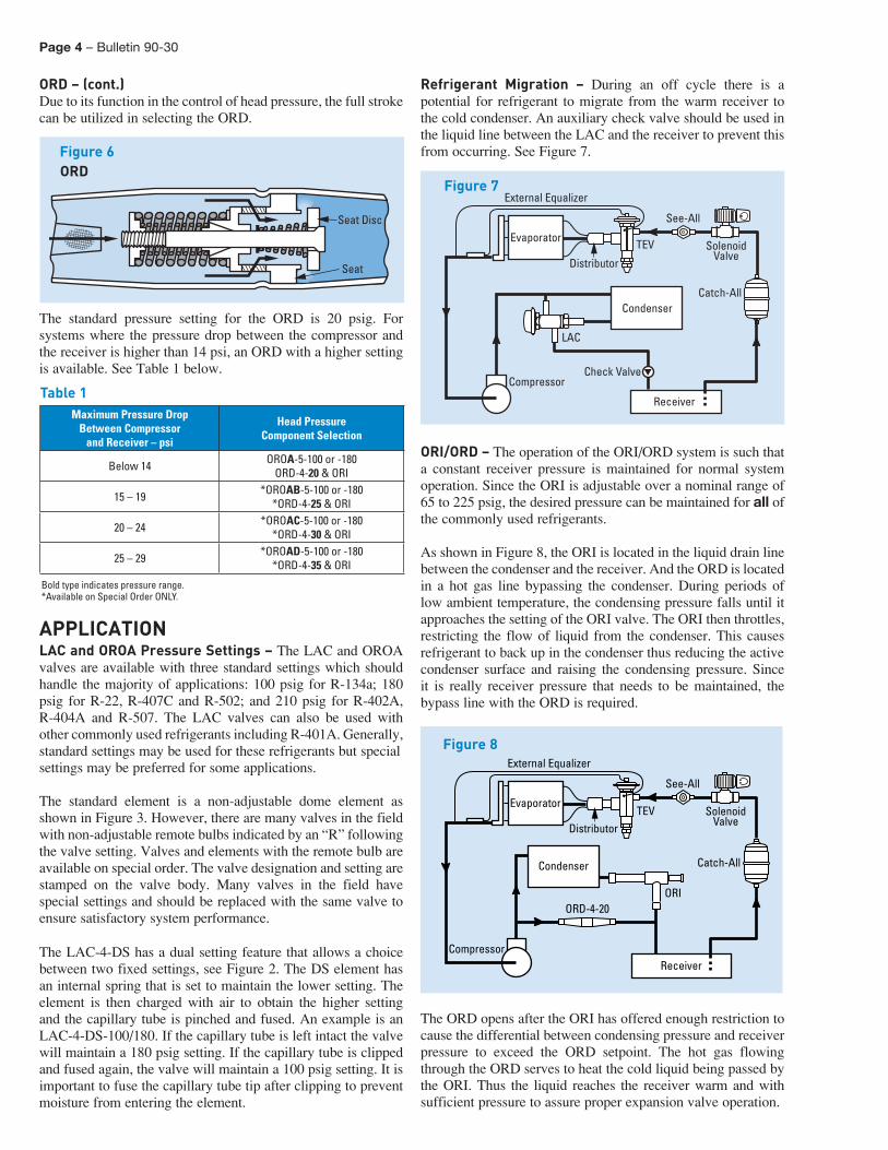
ORD – (cont.) Due to its function in the control of head pressure, the full stroke can be utilized in selecting the ORD.
The standard pressure setting for the ORD is 20 psig. For systems where the pressure drop between the compressor and the receiver is higher than 14 psi, an ORD with a higher setting is available. See Table 1 below.
APPLICATIONLAC and OROA Pressure Settings – The LAC and OROA valves are available with three standard settings which should handle the majority of applications: 100 psig for R-134a; 180 psig for R-22, R-407C and R-502; and 210 psig for R-402A, R-404A and R-507. The LAC valves can also be used with other commonly used refrigerants including R-401A. Generally, standard settings may be used for these refrigerants but specialsettings may be preferred for some applications.
The standard element is a non-adjustable dome element as shown in Figure 3. However, there are many valves in the field with non-adjustable remote bulbs indicated by an “R” following the valve setting. Valves and elements with the remote bulb are available on special order. The valve designation and setting arestamped on the valve body. Many valves in the field have special settings and should be replaced with the same valve to ensure satisfactory system performance.
The LAC-4-DS has a dual setting feature that allows a choice between two fixed settings, see Figure 2. The DS element has an internal spring that is set to maintain the lower setting. The element is then charged with air to obtain the higher setting and the capillary tube is pinched and fused. An example is an LAC-4-DS-100/180. If the capillary tube is left intact the valve will maintain a 180 psig setting. If the capillary tube is clipped and fused again, the valve will maintain a 100 psig setting. It is important to fuse the capillary tube tip after clipping to prevent moisture from entering the element.
Refrigerant Migration – During an off cycle there is a potential for refrigerant to migrate from the warm receiver to the cold condenser. An auxiliary check valve should be used in the liquid line between the LAC and the receiver to prevent this from occurring. See Figure 7.
ORI/ORD – The operation of the ORI/ORD system is such that a constant receiver pressure is maintained for normal system operation. Since the ORI is adjustable over a nominal range of 65 to 225 psig, the desired pressure can be maintained for all of the commonly used refrigerants.
As shown in Figure 8, the ORI is located in the liquid drain line between the condenser and the receiver. And the ORD is located in a hot gas line bypassing the condenser. During periods of low ambient temperature, the condensing pressure falls until it approaches the setting of the ORI valve. The ORI then throttles, restricting the flow of liquid from the condenser. This causes refrigerant to back up in the condenser thus reducing the activecondenser surface and raising the condensing pressure. Since it is really receiver pressure that needs to be maintained, the bypass line with the ORD is required.
The ORD opens after the ORI has offered enough restriction to cause the differential between condensing pressure and receiver pressure to exceed the ORD setpoint. The hot gas flowing through the ORD serves to heat the cold liquid being passed by the ORI. Thus the liquid reaches the receiver warm and with sufficient pressure to assure proper expansion valve operation.
ORDFigure 6
Seat
Seat Disc
Maximum Pressure DropBetween Compressor
and Receiver – psi
Head PressureComponent Selection
Below 14 OROA-5-100 or -180ORD-4-20 & ORI
15 – 19 *OROAB-5-100 or -180*ORD-4-25 & ORI
20 – 24 *OROAC-5-100 or -180*ORD-4-30 & ORI
25 – 29 *OROAD-5-100 or -180*ORD-4-35 & ORI
Table 1
Bold type indicates pressure range.*Available on Special Order ONLY.
Figure 7
SolenoidValve
Catch-All
Compressor
See-All
TEV
External Equalizer
Check Valve
LAC
Receiver
Evaporator
Distributor
Condenser
Figure 8
SolenoidValve
Catch-All
ORIORD-4-20
Compressor
See-All
TEV
External Equalizer
Condenser
Receiver
Evaporator
Distributor
Bulletin 90-30 – Page 5
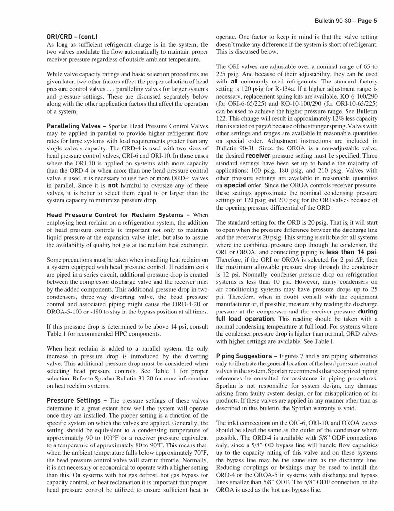
ORI/ORD – (cont.) As long as sufficient refrigerant charge is in the system, the two valves modulate the flow automatically to maintain proper receiver pressure regardless of outside ambient temperature.
While valve capacity ratings and basic selection procedures are given later, two other factors affect the proper selection of head pressure control valves . . . paralleling valves for larger systems and pressure settings. These are discussed separately below along with the other application factors that affect the operation of a system.
Paralleling Valves – Sporlan Head Pressure Control Valves may be applied in parallel to provide higher refrigerant flow rates for large systems with load requirements greater than any single valve’s capacity. The ORD-4 is used with two sizes of head pressure control valves, ORI-6 and ORI-10. In those cases where the ORI-10 is applied on systems with more capacity than the ORD-4 or when more than one head pressure control valve is used, it is necessary to use two or more ORD-4 valves in parallel. Since it is not harmful to oversize any of these valves, it is better to select them equal to or larger than the system capacity to minimize pressure drop.
Head Pressure Control for Reclaim Systems – When employing heat reclaim on a refrigeration system, the addition of head pressure controls is important not only to maintain liquid pressure at the expansion valve inlet, but also to assure the availability of quality hot gas at the reclaim heat exchanger.
Some precautions must be taken when installing heat reclaim on a system equipped with head pressure control. If reclaim coils are piped in a series circuit, additional pressure drop is created between the compressor discharge valve and the receiver inlet by the added components. This additional pressure drop in twocondensers, three-way diverting valve, the head pressure control and associated piping might cause the ORD-4-20 or OROA-5-100 or -180 to stay in the bypass position at all times.
If this pressure drop is determined to be above 14 psi, consult Table 1 for recommended HPC components.
When heat reclaim is added to a parallel system, the only increase in pressure drop is introduced by the diverting valve. This additional pressure drop must be considered when selecting head pressure controls. See Table 1 for proper selection. Refer to Sporlan Bulletin 30-20 for more information on heat reclaim systems.
Pressure Settings – The pressure settings of these valves determine to a great extent how well the system will operate once they are installed. The proper setting is a function of the specific system on which the valves are applied. Generally, the setting should be equivalent to a condensing temperature of approximately 90 to 100°F or a receiver pressure equivalent to a temperature of approximately 80 to 90°F. This means thatwhen the ambient temperature falls below approximately 70°F, the head pressure control valve will start to throttle. Normally, it is not necessary or economical to operate with a higher setting than this. On systems with hot gas defrost, hot gas bypass for capacity control, or heat reclamation it is important that properhead pressure control be utilized to ensure sufficient heat to
operate. One factor to keep in mind is that the valve setting doesn’t make any difference if the system is short of refrigerant. This is discussed below.
The ORI valves are adjustable over a nominal range of 65 to 225 psig. And because of their adjustability, they can be used with all commonly used refrigerants. The standard factory setting is 120 psig for R-134a. If a higher adjustment range is necessary, replacement spring kits are available. KO-6-100/290 (for ORI-6-65/225) and KO-10-100/290 (for ORI-10-65/225) can be used to achieve the higher pressure range. See Bulletin122. This change will result in approximately 12% less capacity than is stated on page 6 because of the stronger spring. Valves with other settings and ranges are available in reasonable quantities on special order. Adjustment instructions are included in Bulletin 90-31. Since the OROA is a non-adjustable valve, the desired receiver pressure setting must be specified. Three standard settings have been set up to handle the majority of applications: 100 psig, 180 psig, and 210 psig. Valves with other pressure settings are available in reasonable quantities on special order. Since the OROA controls receiver pressure, these settings approximate the nominal condensing pressure settings of 120 psig and 200 psig for the ORI valves because of the opening pressure differential of the ORD.
The standard setting for the ORD is 20 psig. That is, it will start to open when the pressure difference between the discharge line and the receiver is 20 psig. This setting is suitable for all systems where the combined pressure drop through the condenser, the ORI or OROA, and connecting piping is less than 14 psi. Therefore, if the ORI or OROA is selected for 2 psi ΔP, then the maximum allowable pressure drop through the condenser is 12 psi. Normally, condenser pressure drop on refrigeration systems is less than 10 psi. However, many condensers on air conditioning systems may have pressure drops up to 25 psi. Therefore, when in doubt, consult with the equipment manufacturer or, if possible, measure it by reading the dischargepressure at the compressor and the receiver pressure during full load operation. This reading should be taken with a normal condensing temperature at full load. For systems where the condenser pressure drop is higher than normal, ORD valves with higher settings are available. See Table l.
Piping Suggestions – Figures 7 and 8 are piping schematics only to illustrate the general location of the head pressure control valves in the system. Sporlan recommends that recognized piping references be consulted for assistance in piping procedures. Sporlan is not responsible for system design, any damage arising from faulty system design, or for misapplication of its products. If these valves are applied in any manner other than as described in this bulletin, the Sporlan warranty is void.
The inlet connections on the ORI-6, ORI-10, and OROA valves should be sized the same as the outlet of the condenser where possible. The ORD-4 is available with 5/8” ODF connections only, since a 5/8” OD bypass line will handle flow capacities up to the capacity rating of this valve and on these systems the bypass line may be the same size as the discharge line. Reducing couplings or bushings may be used to install the ORD-4 or the OROA-5 in systems with discharge and bypass lines smaller than 5/8” ODF. The 5/8” ODF connection on the OROA is used as the hot gas bypass line.
Page 6 – Bulletin 90-30
Piping Suggestions – (cont.) This is available in this manner for two reasons — to allow thebypassed hot gas to flow through the OROA to maintain the element temperature and to eliminate the need of a separate tee connection in the liquid drain line. Compared to the ORI and ORD combination, the OROA-5 installation process is simplified as the ORD-4 is included as an integral part of the OROA
assembly. Inlet strainers are available for all head pressure control valves. Due to the construction of the ORD, it is only available with the strainer included. However, the strainer is optional for the ORI and OROA valves. Just as with any refrigerant flow control devices, the need for an inlet strainer is a function of system cleanliness.
RefrigerantValve
Setting(psig)
MinimumAmbientDesign
Temp. °F
PressureDrop
AcrossValve (psi)
Valve TypeRefrigerant
ValveSetting(psig)
MinimumAmbientDesign
Temp. °F
PressureDrop
AcrossValve (psi)
Valve Type
LAC-4 LAC-5 LAC-10
ORD-4OROA-5
ORI-6ORI-10
LAC-4 LAC-5 LAC-10
ORD-4OROA-5
ORI-6ORI-10
22(180)
-20
1 1.71 3.04 7.30 —
404A(210)
-20
1 1.19 2.11 5.10 — 2 2.41 4.29 10.2 — 2 1.67 2.99 7.16 — 5 3.77 6.77 15.9 — 5 2.62 4.71 11.2 — 10 5.26 9.53 22.1 — 10 3.67 6.64 15.5 — 15 6.37 11.6 26.7 — 15 4.45 8.10 18.7 — 20 7.28 13.4 30.3 — 20 5.09 9.32 21.3 — 25 8.05 14.9 33.4 18.3 25 5.64 10.4 23.6 12.430 8.73 16.2 36.0 25.8 30 6.12 11.3 25.5 17.4
0
1 1.85 3.28 7.85 —
0
1 1.27 2.25 5.42 — 2 2.60 4.63 11.0 — 2 1.79 3.19 7.61 — 5 4.07 7.30 17.1 — 5 2.81 5.03 11.9 —
10 5.69 10.3 23.7 — 10 3.92 7.08 16.5 — 15 6.88 12.5 28.6 — 15 4.75 8.64 19.9 — 20 7.86 14.4 32.5 — 20 5.44 9.94 22.6 — 25 8.70 16.1 35.8 21.0 25 6.02 11.1 25.0 13.930 9.43 17.5 38.6 29.6 30 6.53 12.1 27.0 19.6
20
1 2.03 3.58 8.57 —
20
1 1.38 2.44 5.85 — 2 2.86 5.06 12.0 — 2 1.94 3.45 8.20 — 5 4.46 7.99 18.6 — 5 3.04 5.44 12.7 — 10 6.22 11.3 25.8 — 10 4.25 7.67 17.7 — 15 7.53 13.7 31.1 — 15 5.15 9.35 21.3 — 20 8.60 15.8 35.3 — 20 5.89 10.8 24.3 — 25 9.51 17.6 38.8 25.2 25 6.52 12.0 26.8 16.430 10.3 19.2 41.9 35.5 30 7.07 13.1 29.0 23.1
134a(100)
-20
1 1.36 2.42 5.83 —
507(210)
-20
1 1.17 2.08 5.02 — 2 1.91 3.41 8.17 — 2 1.65 2.94 7.05 — 5 2.98 5.37 12.7 — 5 2.59 4.64 11.0 — 10 4.13 7.54 17.4 — 10 3.62 6.54 15.3 — 15 4.96 9.17 20.8 — 15 4.38 7.98 18.4 — 20 5.62 10.5 23.4 — 20 5.01 9.18 21.0 — 25 6.16 11.6 25.4 13.0 25 5.55 10.2 23.2 12.330 6.62 12.7 27.1 18.4 30 6.02 11.2 25.0 17.3
0
1 1.48 2.64 6.34 —
0
1 1.27 2.24 5.39 — 2 2.09 3.72 8.88 — 2 1.78 3.17 7.56 — 5 3.25 5.86 13.7 — 5 2.79 5.00 11.8 —
10 4.51 8.23 18.9 — 10 3.90 7.05 16.3 — 15 5.42 10.0 22.5 — 15 4.73 8.60 19.7 — 20 6.14 11.5 25.3 — 20 5.40 9.89 22.4 — 25 6.73 12.7 27.6 15.0 25 5.98 11.0 24.8 14.130 7.24 13.8 29.4 21.2 30 6.49 12.0 26.8 19.9
20
1 1.66 2.94 7.03 —
20
1 1.39 2.45 5.86 — 2 2.33 4.15 9.84 — 2 1.95 3.46 8.21 — 5 3.63 6.53 15.2 — 5 3.05 5.46 12.8 — 10 5.03 9.16 20.9 — 10 4.26 7.69 17.7 — 15 6.04 11.1 24.9 — 15 5.16 9.39 21.4 — 20 6.84 12.8 28.0 — 20 5.90 10.8 24.3 — 25 7.51 14.2 30.4 18.1 25 6.54 12.0 26.8 17.030 8.07 15.4 32.4 25.5 30 7.09 13.1 29.0 23.9
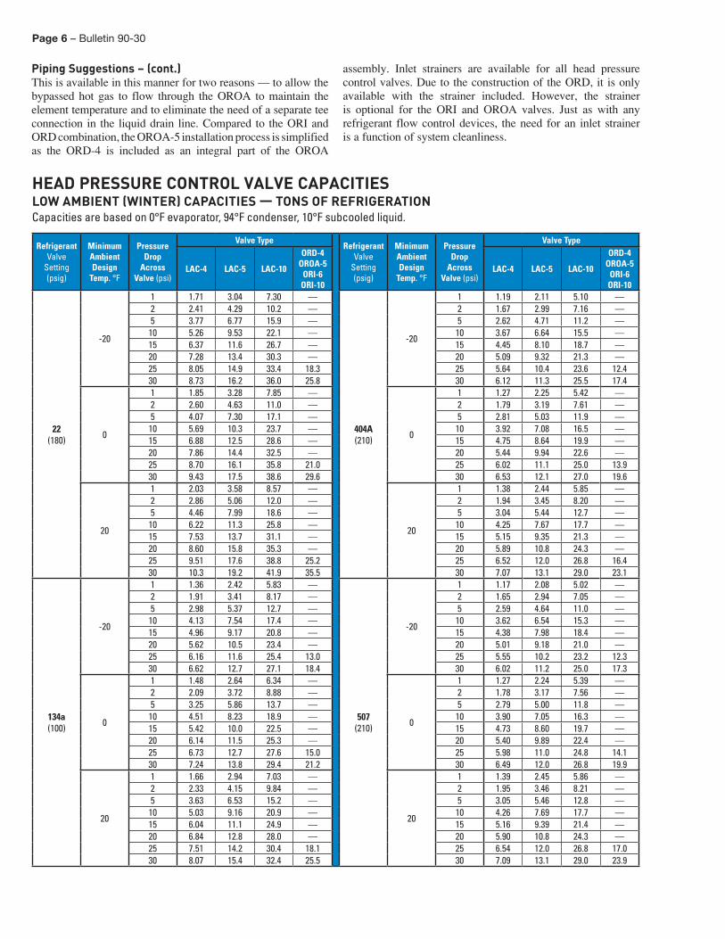
HEAD PRESSURE CONTROL VALVE CAPACITIESLOW AMBIENT (WINTER) CAPACITIES — TONS OF REFRIGERATIONCapacities are based on 0°F evaporator, 94°F condenser, 10°F subcooled liquid.
Bulletin 90-30 – Page 7
Refrigerant
PressureDrop
AcrossValve (psi)
Valve Type
Refrigerant
PressureDrop
AcrossValve (psi)
Valve Type
LAC-
4
LAC-
5
LAC-
10
ORI
-6
ORI
-10
ORO
A-5
ORD
-4
LAC-
4
LAC-
5
LAC-
10
ORI
-6
ORI
-10
ORO
A-5
ORD
-4
22
1 2.57 5.50 11.7 7.35 19.7 10.4 —
404A
1 1.61 3.43 7.33 5.01 13.9 6.49 — 2 3.59 7.78 16.3 10.7 27.2 14.7 — 2 2.25 4.85 10.2 7.29 19.3 9.15 — 3 4.37 9.53 19.7 13.3 32.8 17.9 — 3 2.73 5.94 12.3 9.07 23.3 11.2 — 4 5.02 11.0 22.6 15.5 37.5 20.7 — 4 3.14 6.86 14.1 10.6 26.6 12.9 — 5 5.60 12.3 25.1 17.5 41.6 23.1 — 5 3.50 7.67 15.7 12.0 29.5 14.4 — 6 6.11 13.5 27.3 19.4 45.3 25.3 — 6 3.82 8.40 17.1 13.2 32.1 15.8 — 8 7.02 15.6 31.3 22.6 51.8 29.2 — 8 4.39 9.70 19.6 15.4 36.7 18.2 — 10 7.82 17.4 34.8 25.5 57.5 32.6 — 10 4.89 10.8 21.8 17.4 40.7 20.3 —
134a
1 2.30 4.92 10.5 4.90 12.2 9.31 —
507
1 1.57 3.36 7.17 4.94 13.7 6.36 — 2 3.22 6.96 14.5 7.13 16.8 13.1 — 2 2.20 4.75 9.96 7.19 18.9 8.96 — 3 3.91 8.53 17.6 8.88 20.3 16.1 — 3 2.67 5.82 12.1 8.95 22.9 11.0 — 4 4.49 9.85 20.2 10.4 23.2 18.5 — 4 3.07 6.72 13.8 10.4 26.2 12.6 — 5 5.01 11.0 22.4 11.7 25.8 20.7 — 5 3.42 7.51 15.4 11.8 29.0 14.1 — 6 5.47 12.1 24.5 12.9 28.0 22.6 — 6 3.74 8.23 16.8 13.0 31.6 15.4 — 8 6.28 13.9 28.0 15.1 32.1 26.1 — 8 4.30 9.51 19.2 15.2 36.1 17.8 — 10 7.00 15.6 31.2 17.0 35.6 29.2 — 10 4.79 10.6 21.3 17.1 40.1 19.9 —
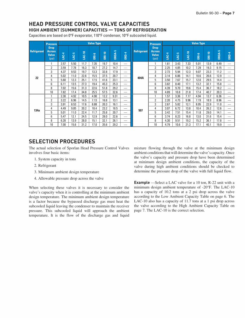
The actual selection of Sporlan Head Pressure Control Valves involves four basic items:
1. System capacity in tons
2. Refrigerant
3. Minimum ambient design temperature
4. Allowable pressure drop across the valve
When selecting these valves it is necessary to consider the valve’s capacity when it is controlling at the minimum ambient design temperature. The minimum ambient design temperature is a factor because the bypassed discharge gas must heat the subcooled liquid leaving the condenser to maintain the receiver pressure. This subcooled liquid will approach the ambient temperature. It is the flow of the discharge gas and liquid
mixture flowing through the valve at the minimum design ambient conditions that will determine the valve’s capacity. Once the valve’s capacity and pressure drop have been determined at minimum design ambient conditions, the capacity of the valve during high ambient conditions should be checked to determine the pressure drop of the valve with full liquid flow.
Example —Select a LAC valve for a 10 ton, R-22 unit with a minimum design ambient temperature of -20°F. The LAC-10 has a capacity of 10.2 tons at a 2 psi drop across the valve according to the Low Ambient Capacity Table on page 6. The LAC-10 also has a capacity of 11.7 tons at a 1 psi drop across the valve according to the High Ambient Capacity Table on page 7. The LAC-10 is the correct selection.
SELECTION PROCEDURES
HEAD PRESSURE CONTROL VALVE CAPACITIESHIGH AMBIENT (SUMMER) CAPACITIES — TONS OF REFRIGERATIONCapacities are based on 0°F evaporator, 110°F condenser, 10°F subcooled liquid.
Page 8 – Bulletin 90-30
Valve Type
StandardFactorySetting(psig)
ConnectionsODF Solder
(Inches)Dimensions (Inches) Weight
(lbs.) ReplacementParts
Inlet(s) Outlet A B C D E F G H I Net Ship
LAC-4
100,180,or
210
1/4 1/4 1.78 1.87 3.02 2.38 4.73
— — — —
0.77 0.85
Repl
acem
ent E
lem
ents
NotAvailable
3/8 3/8 0.80 0.88 1/2 1/2 0.82 0.90
LAC-4-DS3/8 3/8
1.78 1.87 3.02 2.38 6.11 0.87 1.02
1/2 1/2 0.94 1.09
LAC-5
1/2 1/2 1.65 1.60 3.77 2.99
D3L
6.10
R3L
5.59 2.50 2.65 Non-AdjustableDome Element:
D3L (specifysetting) or
Non-AdjustableRemote BulbElement: R3L
(specify setting)
5/8 5/8 1.74 1.69 3.86 3.08 6.19 5.68 2.55 2.70 7/8 7/8 2.23 2.18 4.35 3.57 6.68 6.17 2.60 2.75
1-1/8 1-1/8 2.38 2.33 4.50 3.72 6.83 6.32 2.75 2.90
LAC-10
1-3/8 7/8
7/8 2.82
2.67 4.39 3.43 6.91 6.40 3.20 3.42
1-3/8 1-1/8
1-1/8 2.56 4.83 3.87 7.35 6.84 3.28 3.50
ORI-6-65/225-H 1205/8 5/8
9.85 5.04 6.37 —
— — — — —
1.00 1.25
Inle
t Str
aine
r
825-57/8 7/8 825-7
1-1/8 1-1/8 1.25 1.50 825-9
ORI-10-65/225-H 1201-1/8 1-1/8
11.04 5.48 6.56 — 2.50 2.75825-9
1-3/8 1-3/8 825-11ORD-4-20 20 5/8 5/8 6.56 0.97 — — 0.33 0.50 825-5
OROA-5
100,180,or
210
5/8 5/8
5/8 5.94 3.75 1.88 2.162.00 2.25
825-5
5/8 7/8
7/8 6.19 4.00 2.12 2.41 825-7
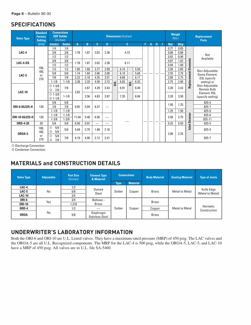
SPECIFICATIONS
MATERIALS and CONSTRUCTION DETAILS
Valve Type Adjustable Port Size(Inches)
Element Type& Material
ConnectionsBody Material Seating Material Type of Joints
Type MaterialLAC-4
No1/2
DomedSteel Solder Copper Brass Metal to Metal Knife Edge
(Metal to Metal)LAC-5 5/8LAC-10 3/4 ORI-6
Yes3/4 Bellows -
BrassSolder Copper
Brass
Metal to Metal HermeticConstruction
ORI-10 1.218ORD-4
No1/2 — Copper
OROA 5/8 DiaphragmStainless Steel Brass
UNDERWRITER’S LABORATORY INFORMATIONBoth the ORI-6 and ORI-10 are U.L. Listed valves. They have a maximum rated pressure (MRP) of 450 psig. The LAC valves and the OROA-5 are all U.L. Recognized components. The MRP for the LAC-4 is 500 psig, while the OROA-5, LAC-5, and LAC-10 have a MRP of 450 psig. All valves are in U.L. file SA-5460.
Discharge Connection. Condenser Connection.
Bulletin 90-30 – Page 9
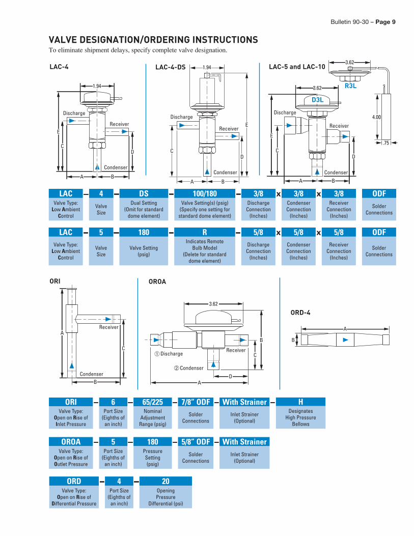
VALVE DESIGNATION/ORDERING INSTRUCTIONSTo eliminate shipment delays, specify complete valve designation.
D
BA
1.94
C
E
Discharge
Receiver
Condenser
DC
BA
1.94
EDischarge
Receiver
Condenser
DC
E
A B
3.62
Discharge
Receiver
Condenser
3.62
.75
4.00
LAC-4 LAC-4-DS LAC-5 and LAC-10
D3L
R3L
LAC – 4 – DS – 100/180 – 3/8 x 3/8 x 3/8 ODFValve Type:
Low AmbientControl
ValveSize
Dual Setting(Omit for standard
dome element)
Valve Setting(s) (psig)(Specify one setting forstandard dome element)
DischargeConnection
(Inches)
CondenserConnection
(Inches)
ReceiverConnection
(Inches)
SolderConnections
LAC – 5 – 180 – R – 5/8 x 5/8 x 5/8 ODFValve Type:
Low AmbientControl
ValveSize
Valve Setting(psig)
Indicates RemoteBulb Model
(Delete for standarddome element)
DischargeConnection
(Inches)
CondenserConnection
(Inches)
ReceiverConnection
(Inches)
SolderConnections
OROA – 5 – 180 – 5/8” ODF – With Strainer Valve Type:
Open on Rise ofOutlet Pressure
Port Size(Eighths of
an inch)
PressureSetting(psig)
SolderConnections
Inlet Strainer(Optional)
ORI – 6 – 65/225 – 7/8” ODF – With Strainer – Valve Type:
Open on Rise ofInlet Pressure
Port Size(Eighths of
an inch)
NominalAdjustment
Range (psig)
SolderConnections
Inlet Strainer(Optional)
ORI OROA
ORD-4
B
C
AReceiver
Condenser DA
B
C
3.62
Discharge Receiver
Condenser
A
B
ORD – 4 – 20 Valve Type:
Open on Rise ofDifferential Pressure
Port Size(Eighths of
an inch)
OpeningPressure
Differential (psi)
H Designates
High PressureBellows

OFFER OF SALEThe items described in this document and other documents and descriptions provided by Parker Hannifin Corporation, its subsidiaries and its authorized distributors (“Seller”) are hereby offered for sale at prices to be established by Seller. This offer and its acceptance by any customer (“Buyer”) shall be governed by all of the following Terms and Conditions. Buyer’s order for any item described in its document, when communicated to Seller verbally, or in writing, shall constitute acceptance of this offer. All goods, services or work described will be referred to as “Products”.
1. Terms and Conditions. Seller’s willingness to offer Products, or accept an order for Products, to or from Buyer is subject to these Terms and Conditions or any newer version of the terms and conditions found on-line at www.parker.com/saleterms/. Seller objects to any contrary or additional terms or conditions of Buyer’s order or any other document issued by Buyer. 2. Price Adjustments; Payments. Prices stated on Seller’s quote or other documentation offered by Seller are valid for 30 days, and do not include any sales, use, or other taxes unless specifically stated. Unless otherwise specified by Seller, all prices are F.C.A. Seller’s facility (INCOTERMS 2010). Payment is subject to credit approval and is due 30 days from the date of invoice or such other term as required by Seller’s Credit Department, after which Buyer shall pay interest on any unpaid invoices at the rate of 1.5% per month or the maximum allowable rate under applicable law. 3. Delivery Dates; Title and Risk; Shipment. All delivery dates are approximate and Seller shall not be responsible for any damages resulting from any delay. Regardless of the manner of shipment, title to any products and risk of loss or damage shall pass to Buyer upon placement of the products with the shipment carrier at Seller’s facility. Unless otherwise stated, Seller may exercise its judgment in choosing the carrier and means of delivery. No deferment of shipment at Buyers’ request beyond the respective dates indicated will be made except on terms that will indemnify, defend and hold Seller harmless against all loss and additional expense. Buyer shall be responsible for any additional shipping charges incurred by Seller due to Buyer’s acts or omissions. 4. Warranty. Seller warrants that the Products sold hereunder shall be free from defects in material or workmanship for a period of twelve months from the date of delivery to Buyer or 2,000 hours of normal use, whichever occurs first. The prices charged for Seller’s products are based upon the exclusive limited warranty stated above, and upon the following disclaimer: DISCLAIMER OF WARRANTY: THIS WARRANTY COMPRISES THE SOLE AND ENTIRE WARRANTY PERTAINING TO PRODUCTS PROVIDED HEREUNDER. SELLER DISCLAIMS ALL OTHER WARRANTIES, EXPRESS AND IMPLIED, INCLUDING DESIGN, MERCHANTABILITY AND FITNESS FOR A PARTICULAR PURPOSE. 5. Claims; Commencement of Actions. Buyer shall promptly inspect all Products upon delivery. No claims for shortages will be allowed unless reported to the Seller within 10 days of delivery. No other claims against Seller will be allowed unless asserted in writing within 30 days after delivery. Buyer shall notify Seller of any alleged breach of warranty within 30 days after the date the defect is or should have been discovered by Buyer. Any action based upon breach of this agreement or upon any other claim arising out of this sale (other than an action by Seller for an amount due on any invoice) must be commenced within 12 months from the date of the breach without regard to the date breach is discovered. 6. LIMITATION OF LIABILITY. UPON NOTIFICATION, SELLER WILL, AT ITS OPTION, REPAIR OR REPLACE A DEFECTIVE PRODUCT, OR REFUND THE PURCHASE PRICE. IN NO EVENT SHALL SELLER BE LIABLE TO BUYER FOR ANY SPECIAL, INDIRECT, INCIDENTAL OR CONSEQUENTIAL DAMAGES ARISING OUT OF, OR AS THE RESULT OF, THE SALE, DELIVERY, NON-DELIVERY, SERVICING, USE OR LOSS OF USE OF THE PRODUCTS OR ANY PART THEREOF, OR FOR ANY CHARGES OR EXPENSES OF ANY NATURE INCURRED WITHOUT SELLER’S WRITTEN CONSENT, EVEN IF SELLER HAS BEEN NEGLIGENT, WHETHER IN CONTRACT, TORT OR OTHER LEGAL THEORY. IN NO EVENT SHALL SELLER’S LIABILITY UNDER ANY CLAIM MADE BY BUYER EXCEED THE PURCHASE PRICE OF THE PRODUCTS. 7. User Responsibility. The user, through its own analysis and testing, is solely responsible for making the final selection of the system and Product and assuring that all performance, endurance, maintenance, safety and warning requirements of the application are met. The user must analyze all aspects of the
application and follow applicable industry standards and Product information. If Seller provides Product or system options, the user is responsible for determining that such data and specifications are suitable and sufficient for all applications and reasonably foreseeable uses of the Products or systems. 8. Loss to Buyer’s Property. Any designs, tools, patterns, materials, drawings, confidential information or equipment furnished by Buyer or any other items which become Buyer’s property, will be considered obsolete and may be destroyed by Seller after two consecutive years have elapsed without Buyer ordering the items manufactured using such property. Seller shall not be responsible for any loss or damage to such property while it is in Seller’s possession or control. 9. Special Tooling. A tooling charge may be imposed for any special tooling, including without limitation, dies, fixtures, molds and patterns, acquired to manufacture Products. Such special tooling shall be and remain Seller’s property notwithstanding payment of any charges by Buyer. In no event will Buyer acquire any interest in apparatus belonging to Seller which is utilized in the manufacture of the Products, even if such apparatus has been specially converted or adapted for such manufacture and notwithstanding any charges paid by Buyer. Unless otherwise agreed, Seller shall have the right to alter, discard or otherwise dispose of any special tooling or other property in its sole discretion at any time. 10. Buyer’s Obligation; Rights of Seller. To secure payment of all sums due or otherwise, Seller shall retain a security interest in the goods delivered and this agreement shall be deemed a Security Agreement under the Uniform Commercial Code. Buyer authorizes Seller as its attorney to execute and file on Buyer’s behalf all documents Seller deems necessary to perfect its security interest. 11. Improper use and Indemnity. Buyer shall indemnify, defend, and hold Seller harmless from any claim, liability, damages, lawsuits, and costs (including attorney fees), whether for personal injury, property damage, patent, trademark or copyright infringement or any other claim, brought by or incurred by Buyer, Buyer’s employees, or any other person, arising out of: (a) improper selection, improper application or other misuse of Products purchased by Buyer from Seller; (b) any act or omission, negligent or otherwise, of Buyer; (c) Seller’s use of patterns, plans, drawings, or specifications furnished by Buyer to manufacture Product; or (d) Buyer’s failure to comply with these terms and conditions. Seller shall not indemnify Buyer under any circumstance except as otherwise provided. 12. Cancellations and Changes. Orders shall not be subject to cancellation or change by Buyer for any reason, except with Seller’s written consent and upon terms that will indemnify, defend and hold Seller harmless against all direct, incidental and consequential loss or damage. Seller may change product features, specifications, designs and availability with notice to Buyer. 13. Limitation on Assignment. Buyer may not assign its rights or obligations under this agreement without the prior written consent of Seller. 14. Force Majeure. Seller does not assume the risk and shall not be liable for delay or failure to perform any of Seller’s obligations by reason of circumstances beyond the reasonable control of Seller (hereinafter “Events of Force Majeure”). Events of Force Majeure shall include without limitation: accidents, strikes or labor disputes, acts of any government or government agency, acts of nature, delays or failures in delivery from carriers or suppliers, shortages of materials, or any other cause beyond Seller’s reasonable control. 15. Waiver and Severability. Failure to enforce any provision of this agreement will not waive that provision nor will any such failure prejudice Seller’s right to enforce that provision in the future. Invalidation of any provision of this agreement by legislation or other rule of law shall not invalidate any other provision herein. The remaining provisions of this agreement will remain in full force and effect. 16. Termination. Seller may terminate this agreement for any reason and at any time by giving Buyer thirty (30) days written notice of termination. Seller may
immediately terminate this agreement, in writing, if Buyer: (a) commits a breach of any provision of this agreement (b) appointments a trustee, receiver or custodian for all or any part of Buyer’s property (c) files a petition for relief in bankruptcy on its own behalf, or by a third party (d) makes an assignment for the benefit of creditors, or (e) dissolves or liquidates all or a majority of its assets. 17. Governing Law. This agreement and the sale and delivery of all Products hereunder shall be deemed to have taken place in and shall be governed and construed in accordance with the laws of the State of Ohio, as applicable to contracts executed and wholly performed therein and without regard to conflicts of laws principles. Buyer irrevocably agrees and consents to the exclusive jurisdiction and venue of the courts of Cuyahoga County, Ohio with respect to any dispute, controversy or claim arising out of or relating to this agreement. 18. Indemnity for Infringement of Intellectual Property Rights. Seller shall have no liability for infringement of any patents, trademarks, copyrights, trade dress, trade secrets or similar rights except as provided in this Section. Seller will defend and indemnify Buyer against allegations of infringement of U.S. patents, U.S. trademarks, copyrights, trade dress and trade secrets (“Intellectual Property Rights”). Seller will defend at its expense and will pay the cost of any settlement or damages awarded in an action brought against Buyer based on an allegation that a Product sold pursuant to this Agreement infringes the Intellectual Property Rights of a third party. Seller’s obligation to defend and indemnify Buyer is contingent on Buyer notifying Seller within ten (10) days after Buyer becomes aware of such allegations of infringement, and Seller having sole control over the defense of any allegations or actions including all negotiations for settlement or compromise. If a Product is subject to a claim that it infringes the Intellectual Property Rights of a third party, Seller may, at its sole expense and option, procure for Buyer the right to continue using the Product, replace or modify the Product so as to make it noninfringing, or offer to accept return of the Product and return the purchase price less a reasonable allowance for depreciation. Notwithstanding the foregoing, Seller shall have no liability for claims of infringement based on information provided by Buyer, or directed to Products delivered hereunder for which the designs are specified in whole or part by Buyer, or infringements resulting from the modification, combination or use in a system of any Product sold hereunder. The foregoing provisions of this Section shall constitute Seller’s sole and exclusive liability and Buyer’s sole and exclusive remedy for infringement of Intellectual Property Rights. 19. Entire Agreement. This agreement contains the entire agreement between the Buyer and Seller and constitutes the final, complete and exclusive expression of the terms of sale. All prior or contemporaneous written or oral agreements or negotiations with respect to the subject matter are herein merged. 20. Compliance with Law, U. K. Bribery Act and U.S. Foreign Corrupt Practices Act. Buyer agrees to comply with all applicable laws and regulations, including both those of the United Kingdom and the United States of America, and of the country or countries of the Territory in which Buyer may operate, including without limitation the U. K. Bribery Act, the U.S. Foreign Corrupt Practices Act (“FCPA”) and the U.S. Anti-Kickback Act (the “Anti-Kickback Act”), and agrees to indemnify and hold harmless Seller from the consequences of any violation of such provisions by Buyer, its employees or agents. Buyer acknowledges that they are familiar with the provisions of the U. K. Bribery Act, the FCPA and the Anti-Kickback Act, and certifies that Buyer will adhere to the requirements thereof. In particular, Buyer represents and agrees that Buyer shall not make any payment or give anything of value, directly or indirectly to any governmental official, any foreign political party or official thereof, any candidate for foreign political office, or any commercial entity or person, for the purpose of influencing such person to purchase products or otherwise benefit the business of Seller.

Parker Hannifin CorporationSporlan Division206 Lange Drive • Washington, MO 63090 USAphone 636 239 1111 • fax 636 239 9130www.sporlan.com
Bulletin 90-30 / 072012© 2012 Parker Hannifin Corporation.