Embed Size (px)
Citation preview


HC-M45-01d
HC-M45monoblockvalve
gene
ralin
dex
3
6
12
14
17
19
| Dealer ccatalogue HHC-MM45
General sspecifications
Standard aarrangement
Inlet aarrangement
Spool ttype
Spool aactuation
Spool rreturn aaction
HC-M45-01d
monoblockvalveHC-M45
analyticalindex
3456789
10111214171925
| Dealer ccatalogue HHC-MM45
General specifications
Identification product
Technical specifications
M45/1 thread
M45/2 thread
M45/3 thead
M45/4 thread
M45/5 thread
M45/6 thread
Inlet arrangement
Spool type
Spool actuation
Spool return action
Joystick control
HC-M45-01d
3
HC-M45monoblockvalve
gene
rals
peci
ficat
ion
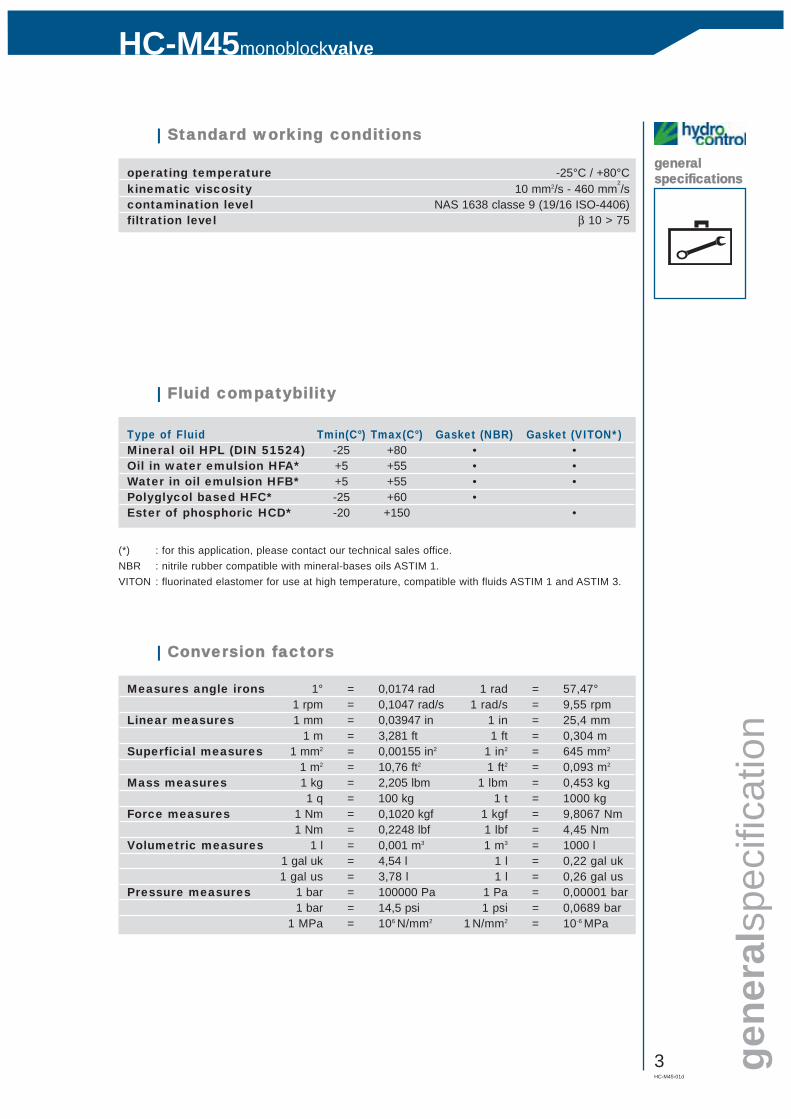
generalspecificationsoperating temperature -25°C / +80°C
kinematic viscosity 10 mm2/s - 460 mm2/s
contamination level NAS 1638 classe 9 (19/16 ISO-4406)filtration level β 10 > 75
| Standard wworking cconditions
Type of Fluid Tmin(C°) Tmax(C°) Gasket (NBR) Gasket (VITON*)Mineral oil HPL (DIN 51524) -25 +80 • •Oil in water emulsion HFA* +5 +55 • •Water in oil emulsion HFB* +5 +55 • •Polyglycol based HFC* -25 +60 •Ester of phosphoric HCD* -20 +150 •
| Fluid ccompatybility
(*) : for this application, please contact our technical sales office.NBR : nitrile rubber compatible with mineral-bases oils ASTIM 1.VITON : fluorinated elastomer for use at high temperature, compatible with fluids ASTIM 1 and ASTIM 3.
Measures angle irons 1° = 0,0174 rad 1 rad = 57,47°1 rpm = 0,1047 rad/s 1 rad/s = 9,55 rpm
Linear measures 1 mm = 0,03947 in 1 in = 25,4 mm1 m = 3,281 ft 1 ft = 0,304 m
Superficial measures 1 mm2 = 0,00155 in2 1 in2 = 645 mm2
1 m2 = 10,76 ft2 1 ft2 = 0,093 m2
Mass measures 1 kg = 2,205 lbm 1 lbm = 0,453 kg1 q = 100 kg 1 t = 1000 kg
Force measures 1 Nm = 0,1020 kgf 1 kgf = 9,8067 Nm1 Nm = 0,2248 lbf 1 lbf = 4,45 Nm
Volumetric measures 1 l = 0,001 m3 1 m3 = 1000 l1 gal uk = 4,54 l 1 l = 0,22 gal uk1 gal us = 3,78 l 1 l = 0,26 gal us
Pressure measures 1 bar = 100000 Pa 1 Pa = 0,00001 bar1 bar = 14,5 psi 1 psi = 0,0689 bar
1 MPa = 106 N/mm2 1 N/mm2 = 10-6 MPa
| Conversion ffactors
4HC-M45-01d
monoblockvalveHC-M45
generalspecification
plate
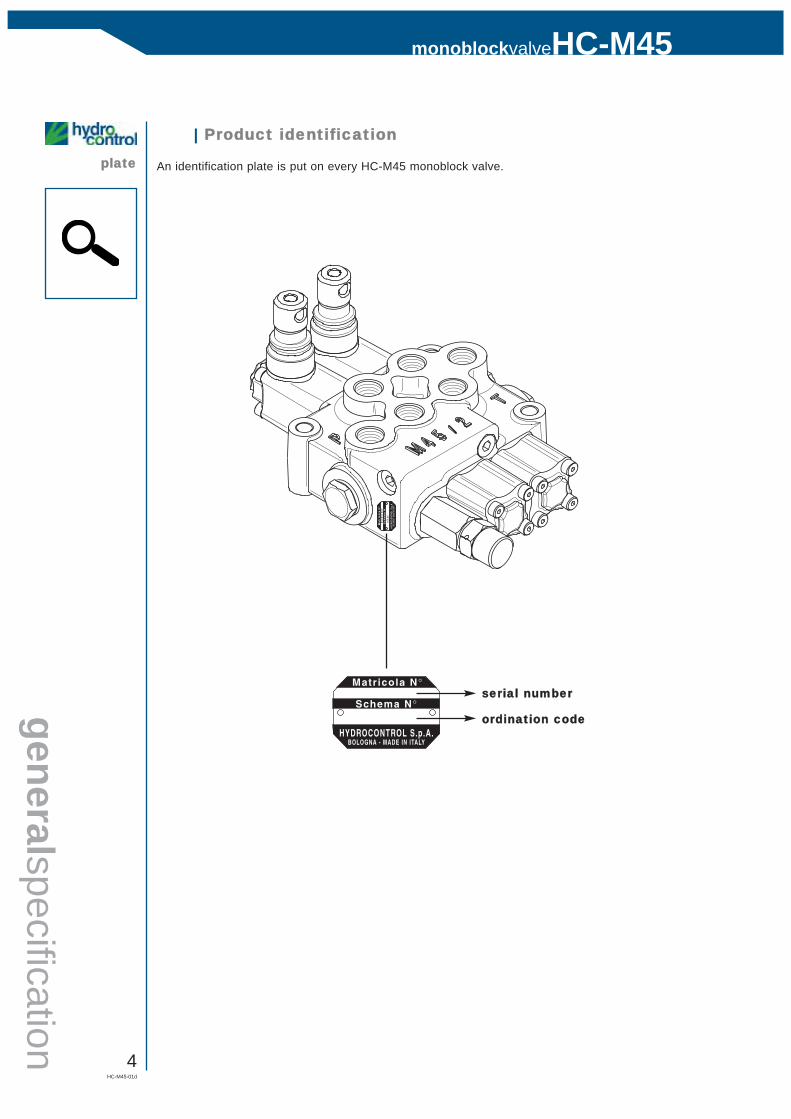
| Product iidentification
An identification plate is put on every HC-M45 monoblock valve.
ordination ccode
serial nnumber

HC-M45-01d
5
HC-M45monoblockvalve
gene
rals
peci
ficat
ion
generalspecificationsflow rate 45 l/min
pressure rate 350 barmax pressure in (T) 20 barworking section number 1 - 6spool stroke 5 + 5 mmspools pitch 35 mm
| Technical sspecifications
| General cclamping ttorque
12
4
35
6
1 Pressure relief valve body 80 Nm2 Pressure relief valve cap 20 Nm3 Check valve 80 Nm4 Fittings in service ports P-A-B-T see table A5 Allen screw (spool actuation side) 6 Nm6 Allen screw (spool return action side) 6 Nm
| Table AA
G03 3/8” BSP 40 NmU03 3/4”-16 UNF 40 Nm
6HC-M45-01d
monoblockvalveHC-M45
M45/1standard
HC-MM45/128
3322
.5
6221
700.5
2441107
15.5
6715
40
3/8" GØ 9
Ø9
84.5
53
M8 M8 1616
220 33
3310
319.5
77
PHPCO
T
A1
B1
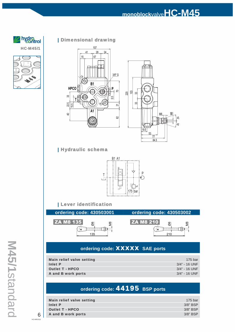
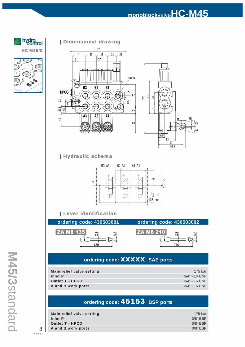
| Dimensional ddrawing
ordering code: xxxxx SAE ports
A1B1
175 bar
PT
| Hydraulic sschema
Main relief valve setting 175 barInlet P 3/4” - 16 UNFOutlet T - HPCO 3/4” - 16 UNFA and B work ports 3/4” - 16 UNF
ordering code: 44195 BSP ports
Main relief valve setting 175 barInlet P 3/8” BSPOutlet T - HPCO 3/8” BSPA and B work ports 3/8” BSP
| Lever iidentification
135
M8
Ø8ZA M8 135
210
M8
Ø8ZA M8 210
ordering code: 430503001 ordering code: 430503002
HC-M45-01d
7
HC-M45monoblockvalve
M45
/2st
anda
rd
HC-MM45/228
3322
.5
6221
700.5
2441142
15.5
1021540
3/8" GØ 9
Ø9
84.5
53
M8 M8 1616
220 33
3310
319.5
77
35
PHPCO
T
A2
B2
A1
B1
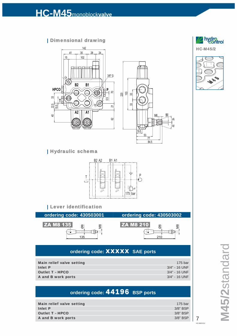
| Dimensional ddrawing
ordering code: xxxxx SAE ports
A2 A1B2 B1
175 bar
PT
| Hydraulic sschema
Main relief valve setting 175 barInlet P 3/4” - 16 UNFOutlet T - HPCO 3/4” - 16 UNFA and B work ports 3/4” - 16 UNF
ordering code: 44196 BSP ports
Main relief valve setting 175 barInlet P 3/8” BSPOutlet T - HPCO 3/8” BSPA and B work ports 3/8” BSP
| Lever iidentification
135
M8
Ø8ZA M8 135
210
M8
Ø8ZA M8 210
ordering code: 430503001 ordering code: 430503002
8HC-M45-01d
monoblockvalveHC-M45
M45/3standard
HC-MM45/328
3322
.5
6221
700.5
2441177
15.5
1371540
3/8" GØ 9
Ø9
84.5
53
M8 M8 1616
220 33
3310
3
19.5
77
3535
A1
B1
A2
B2
A3
B3
T
HPCO P
| Dimensional ddrawing
ordering code: xxxxx SAE ports
A3 A1B3 B1
175 bar
PT
A2B2
| Hydraulic sschema
Main relief valve setting 175 barInlet P 3/4” - 16 UNFOutlet T - HPCO 3/4” - 16 UNFA and B work ports 3/4” - 16 UNF
ordering code: 45153 BSP ports
Main relief valve setting 175 barInlet P 3/8” BSPOutlet T - HPCO 3/8” BSPA and B work ports 3/8” BSP
| Lever iidentification
135
M8
Ø8ZA M8 135
210
M8
Ø8ZA M8 210
ordering code: 430503001 ordering code: 430503002
HC-M45-01d
9
HC-M45monoblockvalve
M45
/4st
anda
rd
HC-MM45/428
3322
.5
6221
700.5
2441212
15.5
17215
40
3/8" GØ 9
Ø9
84.5
53
M8 M8 1616
220 33
3310
3
19.5
77
3535 35
A1
B1
A2
B2
A3
B3
T
HPCO P
A4
B4
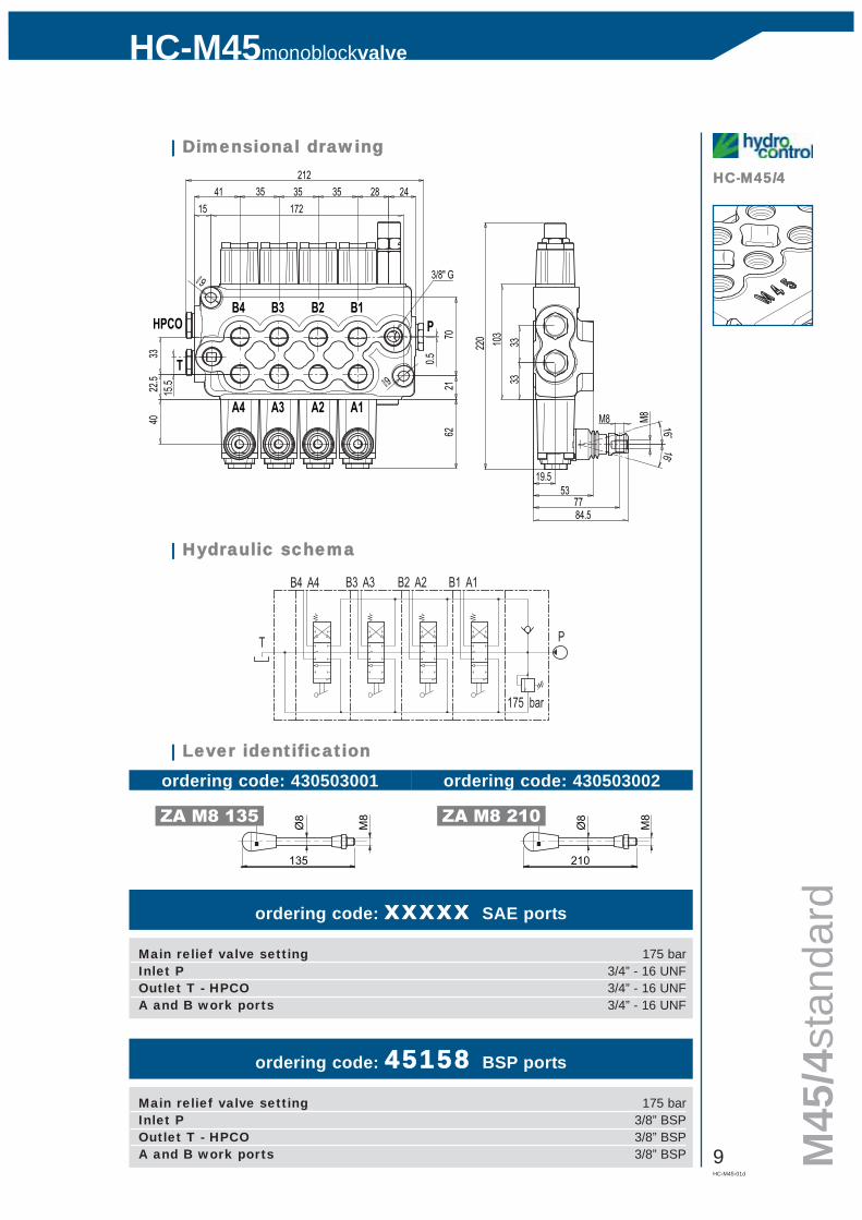
| Dimensional ddrawing
ordering code: xxxxx SAE ports
A4 A1B4 B1
175 bar
PT
A3B3 A2B2
| Hydraulic sschema
Main relief valve setting 175 barInlet P 3/4” - 16 UNFOutlet T - HPCO 3/4” - 16 UNFA and B work ports 3/4” - 16 UNF
ordering code: 45158 BSP ports
Main relief valve setting 175 barInlet P 3/8” BSPOutlet T - HPCO 3/8” BSPA and B work ports 3/8” BSP
| Lever iidentification
135
M8
Ø8ZA M8 135
210
M8
Ø8ZA M8 210
ordering code: 430503001 ordering code: 430503002
10HC-M45-01d
monoblockvalveHC-M45
M45/5standard
HC-MM45/528
3322
.5
6221
700.5
2441247
15.5
20715
40
3/8" GØ 9
Ø9
84.5
53
M8 M8 1616
220 33
3310
3
19.5
77
3535 35 35
A1
B1
A2
B2
A3
B3
A4
B4
A5
B5HPCO
T
P
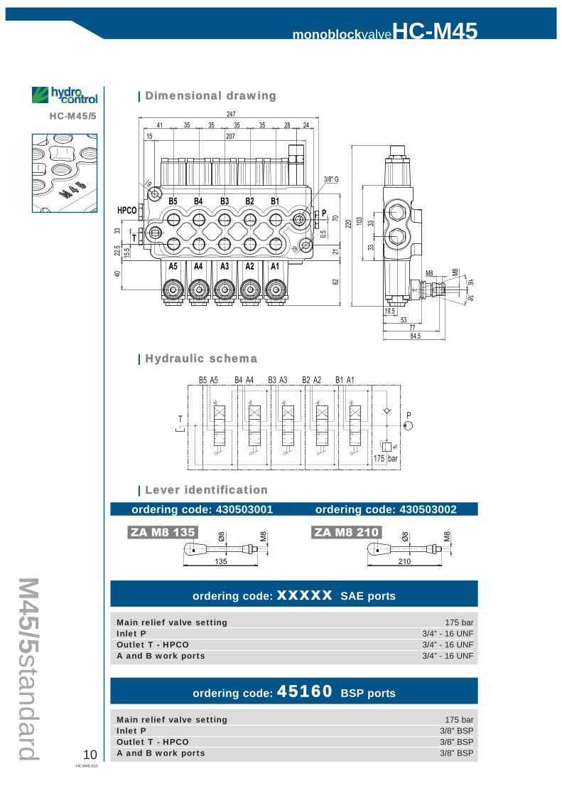
| Dimensional ddrawing
ordering code: xxxxx SAE ports
A5 A1B5 B1
175 bar
PT
A3B3 A2B2A4B4
| Hydraulic sschema
Main relief valve setting 175 barInlet P 3/4” - 16 UNFOutlet T - HPCO 3/4” - 16 UNFA and B work ports 3/4” - 16 UNF
ordering code: 45160 BSP ports
Main relief valve setting 175 barInlet P 3/8” BSPOutlet T - HPCO 3/8” BSPA and B work ports 3/8” BSP
| Lever iidentification
135
M8
Ø8ZA M8 135
210
M8
Ø8ZA M8 210
ordering code: 430503001 ordering code: 430503002

HC-M45-01d
11
HC-M45monoblockvalve
M45
/6st
anda
rd
HC-MM45/628
3322
.5
6221
700.5
2441282
15.5
24215
40
3/8" GØ 9
Ø9
84.5
53
M8 M8 1616
220 33
3310
3
19.5
77
3535 35 3535
A1
B1
A2
B2
A3
B3
A4
B4
A5
B5HPCO
T
P
A6
B6
| Dimensional ddrawing
ordering code: xxxxx SAE ports
A6 A1B6 B1
175 bar
PT
A3B3 A2B2A4B4A5B5
| Hydraulic sschema
Main relief valve setting 175 barInlet P 3/4” - 16 UNFOutlet T - HPCO 3/4” - 16 UNFA and B work ports 3/4” - 16 UNF
ordering code: xxxxx BSP ports
Main relief valve setting 175 barInlet P 3/8” BSPOutlet T - HPCO 3/8” BSPA and B work ports 3/8” BSP
| Lever iidentification
135
M8
Ø8ZA M8 135
210
M8
Ø8ZA M8 210
ordering code: 430503001 ordering code: 430503002
12HC-M45-01d
monoblockvalveHC-M45
inletarrangement
IR 3301
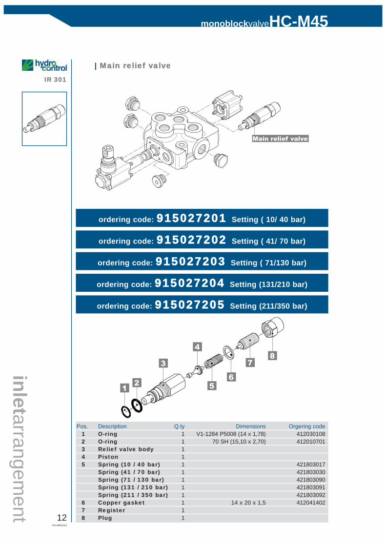
Main relief valve
| Main rrelief vvalve
ordering code: 915027201 Setting ( 10/ 40 bar)
Pos. Description Q.ty Dimensions Orgering code1 O-ring 1 V1-1284 P5008 (14 x 1,78) 4120301082 O-ring 1 70 SH (15,10 x 2,70) 4120107013 Relief valve body 14 Piston 15 Spring (10 / 40 bar) 1 421803017
Spring (41 / 70 bar) 1 421803030Spring (71 / 130 bar) 1 421803090Spring (131 / 210 bar) 1 421803091Spring (211 / 350 bar) 1 421803092
6 Copper gasket 1 14 x 20 x 1,5 4120414027 Register 18 Plug 1
ordering code: 915027202 Setting ( 41/ 70 bar)
ordering code: 915027203 Setting ( 71/130 bar)
ordering code: 915027204 Setting (131/210 bar)
ordering code: 915027205 Setting (211/350 bar)
8
65
4
3
21
7
HC-M45-01d
13
HC-M45monoblockvalve
inle
tarr
ange
men
t
IR 3303
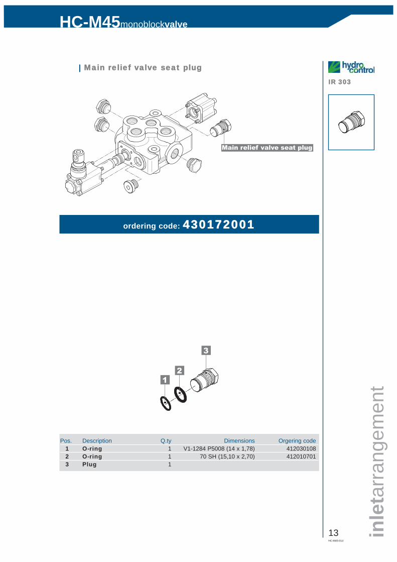
Main relief valve seat plug
| Main rrelief vvalve sseat pplug
ordering code: 430172001
Pos. Description Q.ty Dimensions Orgering code1 O-ring 1 V1-1284 P5008 (14 x 1,78) 4120301082 O-ring 1 70 SH (15,10 x 2,70) 4120107013 Plug 1
3
21
14HC-M45-01d
monoblockvalveHC-M45
spooltype
spools
Spool
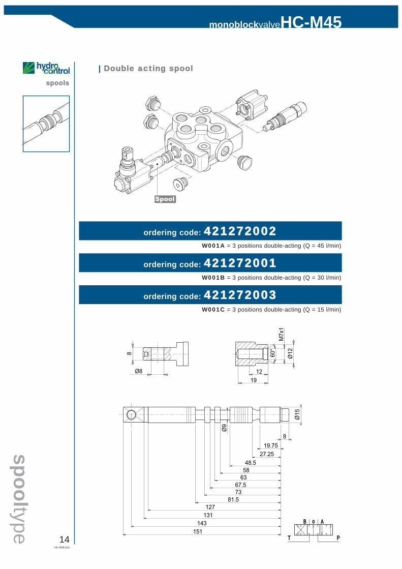
| Double aacting sspool
ordering code: 421272002
ordering code: 421272001
ordering code: 421272003
W001A = 3 positions double-acting (Q = 45 l/min)
W001B = 3 positions double-acting (Q = 30 l/min)
W001C = 3 positions double-acting (Q = 15 l/min)
19.7527.25
48.558
7381.5
143
8
Ø15
127
151
131
67.563
Ø9
M7x
1
12
Ø1260
°
19Ø8
8
HC-M45-01d
15
HC-M45monoblockvalve
spoo
ltype
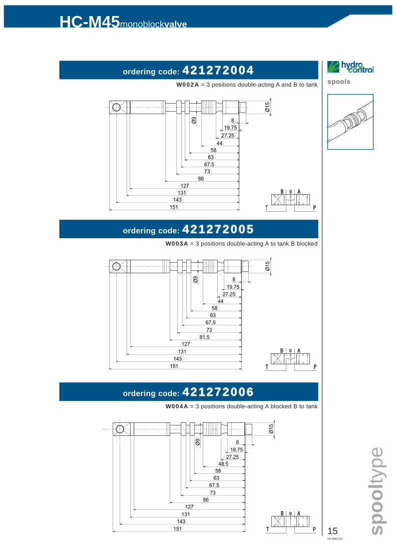
spoolsordering code: 421272004
ordering code: 421272005
ordering code: 421272006
W002A = 3 positions double-acting A and B to tank
W003A = 3 positions double-acting A to tank B blocked
W004A = 3 positions double-acting A blocked B to tank
19.75
4427.25
58
7386
143
8Ø9
Ø15
127
151
131
67.563
19.7527.25
4458
7381.5
143
8Ø9
Ø15
127
151
131
67.563
19.7527.25
48.558
7386
143
8Ø9
Ø15
127
151
131
67.563

16HC-M45-01d
monoblockvalveHC-M45
spooltype
spools
Spool
Plug kit (only for single acting)
| Single aacting sspool
ordering code: 421272007
ordering code: 421272008
W005A = 3 positions single-acting on A
W006A = 3 positions single-acting on B
15.2
27.25
7381.5
143
8Ø
15
127
151
131
Ø9
19.75
48.531.8
58
143
8
Ø15
127
151
131
62
Ø9
ordering ccode:Plug Kit 3/8” BSP = 300001001
Plug Kit 3/4”-16 UNF = 300001006
H002
H349
H350
HC-M45-01d
17
HC-M45monoblockvalve
spoo
lact
uatio
n
H001
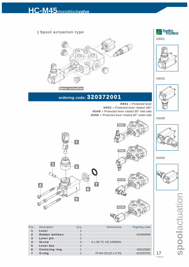
Spool actuation
| Spool aactuation ttype
ordering code: 320372001H001 = Protected lever
H002 = Protected lever rotated 180°H349 = Protected lever rotated 90° inlet side
H350 = Protected lever rotated 90° outlet side
Pos. Description Q.ty Dimensions Orgering code1 Lever 12 Rubber bellows 1 4234030063 Lever pin 14 Screw 4 5 x 55 TC CE UNI59315 Lever box 16 Centering ring 1 4201150027 O-ring 1 70 SH (15,10 x 2,70) 412010701
5
4
3
67
1
2
H001
H002
H349
H350
18HC-M45-01d
monoblockvalveHC-M45
spoolactuation
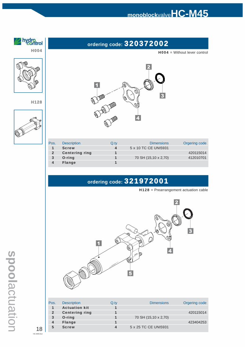
H004ordering code: 320372002
H004 = Without lever control
4
1
3
2
Pos. Description Q.ty Dimensions Orgering code1 Screw 4 5 x 10 TC CE UNI59312 Centering ring 1 4201150143 O-ring 1 70 SH (15,10 x 2,70) 4120107014 Flange 1
ordering code: 321972001H128 = Prearrangement actuation cable
5
1
3
2
4
Pos. Description Q.ty Dimensions Orgering code1 Actuation kit 12 Centering ring 1 4201150143 O-ring 1 70 SH (15,10 x 2,70)4 Flange 1 4234042535 Screw 4 5 x 25 TC CE UNI5931
H128
HC-M45-01d
19
HC-M45monoblockvalve
spoo
lretu
rnac
tion
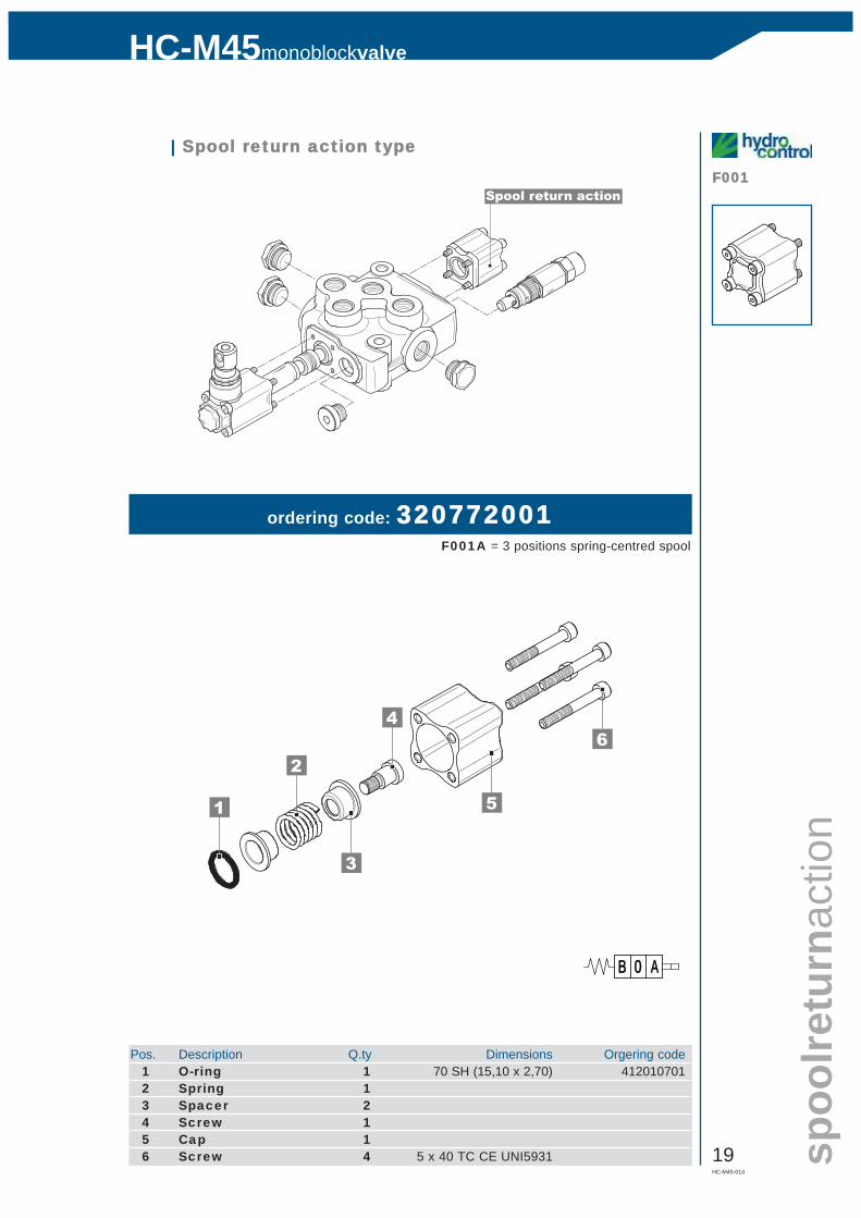
F001Spool return action
| Spool rreturn aaction ttype
ordering code: 320772001F001A = 3 positions spring-centred spool
51
62
4
3
Pos. Description Q.ty Dimensions Orgering code1 O-ring 1 70 SH (15,10 x 2,70) 4120107012 Spring 13 Spacer 24 Screw 15 Cap 16 Screw 4 5 x 40 TC CE UNI5931
AABB 00
20HC-M45-01d
monoblockvalveHC-M45
spoolreturnaction
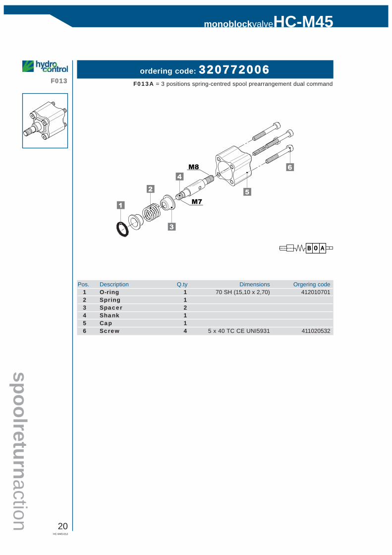
F013ordering code: 320772006
F013A = 3 positions spring-centred spool prearrangement dual command
5
1
6
2
3
4
M7
M8
Pos. Description Q.ty Dimensions Orgering code1 O-ring 1 70 SH (15,10 x 2,70) 4120107012 Spring 13 Spacer 24 Shank 15 Cap 16 Screw 4 5 x 40 TC CE UNI5931 411020532
AABB 00
HC-M45-01d
21
HC-M45monoblockvalve
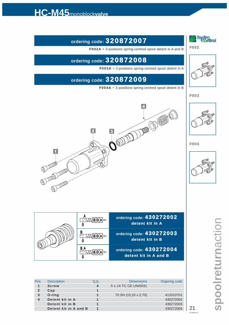
F002ordering code: 320872007
F002A = 3 positions spring-centred spool detent in A and B
Pos. Description Q.ty Dimensions Orgering code1 Screw 4 5 x 14 TC CE UNI59312 Cap 13 O-ring 1 70 SH (15,10 x 2,70) 4120107014 Detent kit in A 1 430272002
Detent kit in B 1 430272003Detent kit in A and B 1 430272004
ordering code: 320872008F003A = 3 positions spring-centred spool detent in A
F003
F004
spoo
lretu
rnac
tion
ordering code: 320872009F004A = 3 positions spring-centred spool detent in B
3
4
1
2
ordering code: 430272002detent kkit iin AA
ordering code: 430272003detent kkit iin BB
ordering code: 430272004detent kkit iin AA aand BB
AABB 00BB AA
00
AABB 00AA
00
AABB 00BB
00

22HC-M45-01d
monoblockvalveHC-M45
spoolreturnaction
F073 F073A = detent kit in 3 positions
3
1
2 4
5
9
76
8
Pos. Description Q.ty Dimensions Orgering code1 Screw 1 5 x 14 TC CE UNI59312 Cap 13 Spacer 24 Spring 15 O-ring 1 70 SH (15,10 x 2,70) 4120107016 Seeger 1 UNI7437 D.21I 4111321017 Copper 18 Spacer 19 Prearrangement kit 1 430202006
ordering code: 320872013
HC-M45-01d
23
HC-M45monoblockvalve
spoo
lretu
rnac
tion
F020AF021A
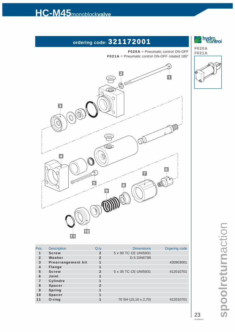
ordering code: 321172001F020A = Pneumatic control ON-OFF
F021A = Pneumatic control ON-OFF rotated 180°
3
4
5
7
98
6
10
12
11
Pos. Description Q.ty Dimensions Orgering code1 Screw 2 5 x 90 TC CE UNI59312 Washer 2 D.5 DIN67983 Prearrangement kit 1 4309030014 Flange 15 Screw 2 5 x 35 TC CE UNI5931 4120107016 Joint 17 Cylindre 18 Spacer 29 Spring 1
10 Spacer 111 O-ring 1 70 SH (15,10 x 2,70) 412010701
24HC-M45-01d
monoblockvalveHC-M45
spoolreturnaction
F022AF023A
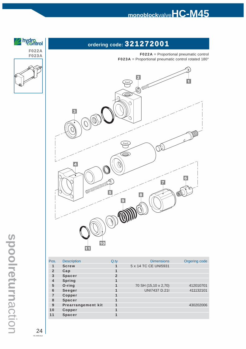
ordering code: 321272001F022A = Proportional pneumatic control
F023A = Proportional pneumatic control rotated 180°
3
4
5
7
98
6
10
12
11
Pos. Description Q.ty Dimensions Orgering code1 Screw 1 5 x 14 TC CE UNI59312 Cap 13 Spacer 24 Spring 15 O-ring 1 70 SH (15,10 x 2,70) 4120107016 Seeger 1 UNI7437 D.21I 4111321017 Copper 18 Spacer 19 Prearrangement kit 1 430202006
10 Copper 111 Spacer 1
HC-M45-01d
25
HC-M45monoblockvalve
joys
tickc
ontro
l
H009H010
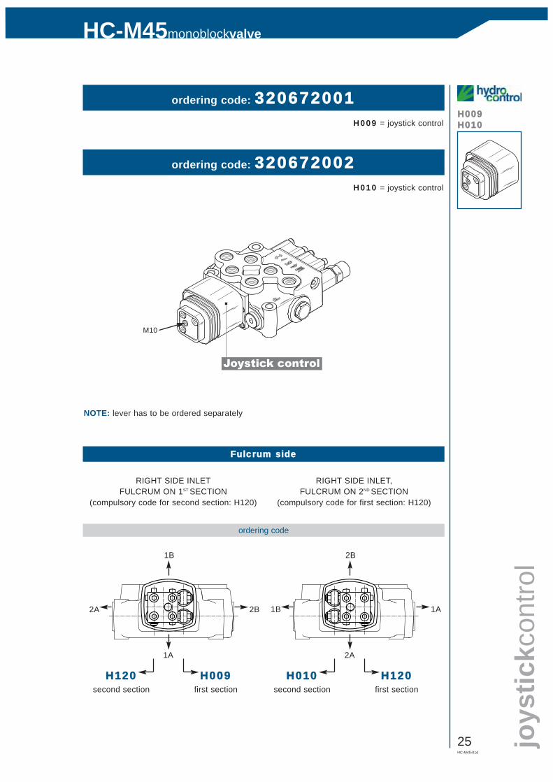
ordering code: 320672001H009 = joystick control
ordering code: 320672002H010 = joystick control
Joystick control
Fulcrum sside
RIGHT SIDE INLETFULCRUM ON 1ST SECTION
(compulsory code for second section: H120)
RIGHT SIDE INLET,FULCRUM ON 2ND SECTION
(compulsory code for first section: H120)
ordering code
1B
1A
2A 2B
H120second section
H009first section
H010second section
H120first section
1B 1A
2B
2A
NOTE: lever has to be ordered separately
M10