Embed Size (px)
Citation preview

Store Systems:
Hardware Service Manual forPoint-of-Sale Input/Output Devices
SY27-0339-02


IBM Store Systems:
Hardware Service Manual forPoint-of-Sale Input/Output Devices
SY27-0339-02

Note
Before using this information and the products it supports, be sure to read the general information under “Notices”on page v. Translations of the safety notices can be found in IBM 4693/4694 Point of Sale Terminals: ProductSafety Information, P/N 60G1330.
Third Edition (October 1995)
This is the third edition of the IBM Store Systems: Hardware Service Manual for Point of Sale Input/Output Devices.
Order publications through your IBM representative or the IBM branch office serving your locality. Publications are not stocked at theaddress given below.
Forms for readers’ comments appear at the back of this publication. If the forms have been removed, address your comments to:
IBM Corporation, Information Development, Department CJMAP.O. Box 12195Research Triangle Park, North Carolina 27709
USA
When you send information to IBM, you grant IBM a nonexclusive right to use or distribute the information in any way it believesappropriate without incurring any obligation to you.
Copyright International Business Machines Corporation 1993, 1995. All rights reserved.Note to U.S. Government Users — Documentation related to restricted rights — Use, duplication or disclosure is subject torestrictions set forth in GSA ADP Schedule Contract with IBM Corp.
Contents
Notices . . . . . . . . . . . . . . . . . . . . . . . . . . . . . . . . . . . . . . . . . . . . . . . . . . . . . . . . vTrademarks . . . . . . . . . . . . . . . . . . . . . . . . . . . . . . . . . . . . . . . . . . . . . . . . . . . vElectronic Emission Notices . . . . . . . . . . . . . . . . . . . . . . . . . . . . . . . . . . . . . . . . . . viGeneral Safety Considerations . . . . . . . . . . . . . . . . . . . . . . . . . . . . . . . . . . . . . . . . vi
Electrostatic Discharge (ESD) . . . . . . . . . . . . . . . . . . . . . . . . . . . . . . . . . . . . . . . . . . viiEuropean Union (EU) Electromagnetic Compatibility . . . . . . . . . . . . . . . . . . . . . . . . . . . . viiiLaser Product Identification . . . . . . . . . . . . . . . . . . . . . . . . . . . . . . . . . . . . . . . . . . viii
Preface . . . . . . . . . . . . . . . . . . . . . . . . . . . . . . . . . . . . . . . . . . . . . . . . . . . . . . . ixStore System Libraries . . . . . . . . . . . . . . . . . . . . . . . . . . . . . . . . . . . . . . . . . . . . . . . xStore System Related Publications — Hardware . . . . . . . . . . . . . . . . . . . . . . . . . . . . . . . . xSummary of Changes . . . . . . . . . . . . . . . . . . . . . . . . . . . . . . . . . . . . . . . . . . . . . . . xi
Chapter 1. START . . . . . . . . . . . . . . . . . . . . . . . . . . . . . . . . . . . . . . . . . . . . . . . 1-1Tests . . . . . . . . . . . . . . . . . . . . . . . . . . . . . . . . . . . . . . . . . . . . . . . . . . . . . . . . 1-1Messages . . . . . . . . . . . . . . . . . . . . . . . . . . . . . . . . . . . . . . . . . . . . . . . . . . . . . 1-2Symptoms . . . . . . . . . . . . . . . . . . . . . . . . . . . . . . . . . . . . . . . . . . . . . . . . . . . . . 1-3
Chapter 2. Point-Of-Sale Cash Drawers . . . . . . . . . . . . . . . . . . . . . . . . . . . . . . . . . . 2-1Point-of-Sale Cash Drawer (light gray) . . . . . . . . . . . . . . . . . . . . . . . . . . . . . . . . . . . . 2-3Point-of-Sale Cash Drawer (dark gray) . . . . . . . . . . . . . . . . . . . . . . . . . . . . . . . . . . . . 2-8Compact Cash Drawer . . . . . . . . . . . . . . . . . . . . . . . . . . . . . . . . . . . . . . . . . . . . . 2-16Replacing the Compact Cash Drawer Integration Cover . . . . . . . . . . . . . . . . . . . . . . . . . 2-25
Chapter 3. Point-of-Sale Displays . . . . . . . . . . . . . . . . . . . . . . . . . . . . . . . . . . . . . . 3-1Flat Panel Display . . . . . . . . . . . . . . . . . . . . . . . . . . . . . . . . . . . . . . . . . . . . . . . . 3-2Flat Panel Display Symptoms . . . . . . . . . . . . . . . . . . . . . . . . . . . . . . . . . . . . . . . . . . 3-5Flat Panel Display Component Removal and Replacement . . . . . . . . . . . . . . . . . . . . . . . . 3-6Sure Point Touch Screens . . . . . . . . . . . . . . . . . . . . . . . . . . . . . . . . . . . . . . . . . . . 3-8Touch Display Symptoms . . . . . . . . . . . . . . . . . . . . . . . . . . . . . . . . . . . . . . . . . . . 3-11Monochrome Touch Display Component Removal and Replacement . . . . . . . . . . . . . . . . . . 3-13Color Touch Display Component Removal and Replacement . . . . . . . . . . . . . . . . . . . . . . 3-15Removing and Replacing the Accessory Kits . . . . . . . . . . . . . . . . . . . . . . . . . . . . . . . . 3-1940-Character Vacuum Fluorescent Display II . . . . . . . . . . . . . . . . . . . . . . . . . . . . . . . 3-2340-Character Alphanumeric Display . . . . . . . . . . . . . . . . . . . . . . . . . . . . . . . . . . . . . 3-24
Chapter 4. Point-of-Sale Keyboards . . . . . . . . . . . . . . . . . . . . . . . . . . . . . . . . . . . . 4-1Keyboard and Card Reader Messages . . . . . . . . . . . . . . . . . . . . . . . . . . . . . . . . . . . . 4-3Keyboard and Card Reader Symptoms . . . . . . . . . . . . . . . . . . . . . . . . . . . . . . . . . . . . 4-5
Chapter 5. Point-of-Sale Printer Model 1 or Model 2 . . . . . . . . . . . . . . . . . . . . . . . . . . 5-1Printer Stand-Alone Test Procedure . . . . . . . . . . . . . . . . . . . . . . . . . . . . . . . . . . . . . . 5-4Printer Messages . . . . . . . . . . . . . . . . . . . . . . . . . . . . . . . . . . . . . . . . . . . . . . . . . 5-6Printer Symptoms . . . . . . . . . . . . . . . . . . . . . . . . . . . . . . . . . . . . . . . . . . . . . . . . 5-8Printer Repair Procedures (Models 1 and 2) . . . . . . . . . . . . . . . . . . . . . . . . . . . . . . . . 5-12Printer Sensor Checks . . . . . . . . . . . . . . . . . . . . . . . . . . . . . . . . . . . . . . . . . . . . . 5-48
Chapter 6. Point-of-Sale Printer Models 3, 3R, 4, 4A, 4R . . . . . . . . . . . . . . . . . . . . . . . . 6-1TEST 4100: Stand-Alone Printer Test . . . . . . . . . . . . . . . . . . . . . . . . . . . . . . . . . . . . 6-4Stand-Alone MICR Test . . . . . . . . . . . . . . . . . . . . . . . . . . . . . . . . . . . . . . . . . . . . . 6-8Printer Messages . . . . . . . . . . . . . . . . . . . . . . . . . . . . . . . . . . . . . . . . . . . . . . . . 6-10
Copyright IBM Corp. 1993, 1995 iii
Printer Symptoms . . . . . . . . . . . . . . . . . . . . . . . . . . . . . . . . . . . . . . . . . . . . . . . 6-11MAP 4110: CR or JNL Paper Advances Continuously . . . . . . . . . . . . . . . . . . . . . . . . . . 6-13MAP 4120: Paper Cutter Does Not Cut Properly . . . . . . . . . . . . . . . . . . . . . . . . . . . . . 6-14MAP 4130: CR Paper Does Not Advance . . . . . . . . . . . . . . . . . . . . . . . . . . . . . . . . . 6-16MAP 4140: CR Paper Jams . . . . . . . . . . . . . . . . . . . . . . . . . . . . . . . . . . . . . . . . . 6-19MAP 4150: CR Station is Overprinting . . . . . . . . . . . . . . . . . . . . . . . . . . . . . . . . . . . 6-21MAP 4160: DI Paper Advances Continuously . . . . . . . . . . . . . . . . . . . . . . . . . . . . . . . 6-22MAP 4170: DI Station Does Not Feed Documents Correctly or Is Overprinting . . . . . . . . . . . . 6-23MAP 4180: Home Errors . . . . . . . . . . . . . . . . . . . . . . . . . . . . . . . . . . . . . . . . . . . 6-27MAP 4190: JNL Paper Does Not Advance . . . . . . . . . . . . . . . . . . . . . . . . . . . . . . . . . 6-29MAP 4200: JNL Station Not Printing . . . . . . . . . . . . . . . . . . . . . . . . . . . . . . . . . . . . 6-32MAP 4210: JNL Station is Overprinting . . . . . . . . . . . . . . . . . . . . . . . . . . . . . . . . . . . 6-35MAP 4220: MICR Does Not Read Correctly . . . . . . . . . . . . . . . . . . . . . . . . . . . . . . . . 6-36MAP 4230: Power Problems . . . . . . . . . . . . . . . . . . . . . . . . . . . . . . . . . . . . . . . . . 6-39MAP 4240: Printed Characters are Light . . . . . . . . . . . . . . . . . . . . . . . . . . . . . . . . . . 6-43MAP 4250: Printed Characters Missing One or More Dot Rows . . . . . . . . . . . . . . . . . . . . 6-45MAP 4260: Printed Characters Are Smudged . . . . . . . . . . . . . . . . . . . . . . . . . . . . . . . 6-47MAP 4270: Printer Indicator Light Always On or Comes On Randomly . . . . . . . . . . . . . . . . 6-48MAP 4280: Printer Indicator Light Not On . . . . . . . . . . . . . . . . . . . . . . . . . . . . . . . . . 6-49MAP 4290: Printer Indicator Light Not On When A Document Is Inserted . . . . . . . . . . . . . . . 6-51MAP 4300: Printer Not Printing Any Characters . . . . . . . . . . . . . . . . . . . . . . . . . . . . . . 6-53MAP 4310: Ribbon Damaged by Printer . . . . . . . . . . . . . . . . . . . . . . . . . . . . . . . . . . 6-55MAP 4320: Ribbon Does Not Advance . . . . . . . . . . . . . . . . . . . . . . . . . . . . . . . . . . . 6-56MAP 4330: CR Motor Resistance Checks . . . . . . . . . . . . . . . . . . . . . . . . . . . . . . . . . 6-57MAP 4340: Paper Cutter Motor Resistance Checks . . . . . . . . . . . . . . . . . . . . . . . . . . . 6-58MAP 4350: DI Motor Resistance Checks . . . . . . . . . . . . . . . . . . . . . . . . . . . . . . . . . . 6-59MAP 4360: JNL Motor Resistance Checks . . . . . . . . . . . . . . . . . . . . . . . . . . . . . . . . . 6-60MAP 4370: Print Head Resistance Checks . . . . . . . . . . . . . . . . . . . . . . . . . . . . . . . . 6-61MAP 4380: Transport Motor Resistance Checks . . . . . . . . . . . . . . . . . . . . . . . . . . . . . 6-62Printer Sensor Checks . . . . . . . . . . . . . . . . . . . . . . . . . . . . . . . . . . . . . . . . . . . . . 6-63Printer Adjustments . . . . . . . . . . . . . . . . . . . . . . . . . . . . . . . . . . . . . . . . . . . . . . 6-67Removal and Replacement Procedures . . . . . . . . . . . . . . . . . . . . . . . . . . . . . . . . . . . 6-70
Chapter 7. 4678 OEM Input/Output Devices . . . . . . . . . . . . . . . . . . . . . . . . . . . . . . . 7-1Signature Capture Device (Models A01 and A02) . . . . . . . . . . . . . . . . . . . . . . . . . . . . . . 7-1Signature Capture Device Symptoms . . . . . . . . . . . . . . . . . . . . . . . . . . . . . . . . . . . . . 7-2
Appendix A. Display and Keyboard Options . . . . . . . . . . . . . . . . . . . . . . . . . . . . . . . A-1
Appendix B. Preventive Maintenance for I/O Devices . . . . . . . . . . . . . . . . . . . . . . . . . B-1
Appendix C. Removing and Replacing the Keylock . . . . . . . . . . . . . . . . . . . . . . . . . . C-1
Appendix D. Special Tools . . . . . . . . . . . . . . . . . . . . . . . . . . . . . . . . . . . . . . . . . . D-1Expendable Supplies . . . . . . . . . . . . . . . . . . . . . . . . . . . . . . . . . . . . . . . . . . . . . . . D-1Lubricant Equivalents . . . . . . . . . . . . . . . . . . . . . . . . . . . . . . . . . . . . . . . . . . . . . . D-1
Appendix E. Procedures For Model 1 and 2 Printer Not Recommended for Field Personnel . E-1
Index . . . . . . . . . . . . . . . . . . . . . . . . . . . . . . . . . . . . . . . . . . . . . . . . . . . . . . . . X-1
iv I/O Devices - Hardware Service Manual
Notices
The following paragraph does not apply to the United Kingdom or any country where such provisions areinconsistent with local law: INTERNATIONAL BUSINESS MACHINES CORPORATION PROVIDES THISPUBLICATION "AS IS" WITHOUT WARRANTY OF ANY KIND, EITHER EXPRESS OR IMPLIED,INCLUDING, BUT NOT LIMITED TO THE IMPLIED WARRANTIES OF MERCHANTABILITY ORFITNESS FOR A PARTICULAR PURPOSE. Some states do not allow disclaimer of express or impliedwarranties in certain transactions, therefore, this statement may not apply to you.
References in this publication to IBM products, programs, or services do not imply that IBM intends tomake these available in all countries in which IBM operates. Any reference to an IBM product, program,or service is not intended to state or imply that only IBM’s product, program, or service may be used. Anyfunctionally equivalent product, program, or service that does not infringe any of IBM’s intellectual propertyrights may be used instead of the IBM product, program, or service. Evaluation and verification ofoperation in conjunction with other products, except those expressly designated by IBM, are the user’sresponsibility.
IBM may have patents or pending patent applications covering subject matter in this document. Thefurnishing of this document does not give you any license to these patents. You can send licenseinquiries, in writing, to the IBM Director of Licensing, IBM Corporation, 500 Columbus Avenue, Thornwood,NY 10594 USA.
Trademarks
The following terms used in this publication are trademarks of the IBM Corporation in the United States ofAmerica or other countries or both:
Windows is a trademark of Microsoft Corporation.
PC Direct is a trademark of Ziff Communications Company and is used by IBM Corporation under license.
UNIX is a registered trademark in the United States and other countries licensed exclusively throughX/Open Company Limited.
Other company, product, and service names, which may be denoted by a double asterisk (**), may betrademarks or service marks of others.
IBM Micro Channel Sure Point Touch Screen
Contents v

Electronic Emission Notices
Federal Communications Commission (FCC) StatementNote: This equipment has been tested and found to comply with the limits for a Class A digital device,pursuant to Part 15 of the FCC Rules. These limits are designed to provide reasonable protection againstharmful interference when the equipment is operated in a commercial environment. This equipmentgenerates, uses, and can radiate radio frequency energy and, if not installed and used in accordance withthe instruction manual, may cause harmful interference to radio communications. Operation of thisequipment in a residential area is likely to cause harmful interference, in which case the user will berequired to correct the interference at his own expense.
Properly shielded and grounded cables and connectors must be used in order to meet FCC emissionlimits. IBM is not responsible for any radio or television interference caused by using other thanrecommended cables and connectors or by unauthorized changes or modifications to this equipment.Unauthorized changes or modifications could void the user's authority to operate the equipment.
This device complies with Part 15 of the FCC Rules. Operation is subject to the following two conditions:(1) this device may not cause harmful interference, and (2) this device must accept any interferencereceived, including interference that may cause undesired operation.
Canada ICES – Class A:
This class A digital apparatus meets the requirements of the Canadian Interference-Causing EquipmentRegulations.
Cet appareil numérique de la classe A respecte toutes les exigences du Réglement sur le matérielbrouilleur du Canada.
United Kingdom Office of Telecommunications Statement of Compliance:
The United Kingdom Telecommunications Act 1984. This apparatus is approved under numberNS/G/1234/J/100003 for indirect connections to the public telecommunications systems in the UnitedKingdom.
General Safety Considerations
The following general safety considerations should be observed whenever you work with electricity or withany electronic equipment.
DANGER
Never work on equipment or connect or disconnect signal cables during periods oflightning activity.
CAUTION:For your safety, connect equipment requiring electrical power to a properly wired and groundedoutlet.
The following general safety considerations should be observed whenever you work with a point-of-saleprinter.
vi I/O Devices - Hardware Service Manual
CAUTION:For safety when running the printer test, make sure personal articles such as ties, necklaces, orbracelets do not get caught in the moving print head.
The following general consideration should be observed whenever you exchange batteries in apoint-of-sale terminal.
Replaceable Lithium Battery inside system unit.
Non-replaceable Lithium Battery inside adapter.
Nickel-Cadmium Batteries:
Some Point-of-Sale products contain a nickel-cadmium battery. The battery must be recycled or disposedof properly. Recycling facilities may not be available in your area.
In the United States of America, IBM has established a collection process for reuse, recycling, or properdisposal of used IBM nickel-cadmium batteries and battery packs. For information on proper disposal ofthe nickel-cadmium batteries in this product, please contact IBM at 1-800-426-4333. Please have the IBMpart listed on the battery available prior to your call.
For information on disposal of nickel-cadmium batteries outside the United States, contact your local wastedisposal facility.
Electrostatic Discharge (ESD)
Attention ESD damage can occur when there is a difference in charge between the part, the product, andthe service person. No damage will occur if the service person and the part being installed are at thesame charge level.
ESD Damage Prevention
Anytime a service action involves physical contact with logic cards, modules, back-panel pins, or otherESD sensitive (ESDS) parts, the service person must be connected to an ESD common ground point onthe product through the ESD wrist strap and cord.
The ESD ground clip can be attached to any frame ground, ground braid, green wire ground, or the roundground prong on the AC power plug. Coax or connector outside shells can also be used.
Handling Removed Cards
Logic cards removed from a product should be placed in ESD protective containers. No other objectshould be allowed inside the ESD container with the logic card. Attach tags or reports that mustaccompany the card to the outside of the container.
Contents vii

European Union (EU) Electromagnetic Compatibility
This product is in conformity with the protection requirements of EC Council Directive 89/336/EEC on theapproximation of the laws of the Member States relating to electromagnetic compatibility. IBM cannotaccept responsibility for any failure to satisfy the protection requirements resulting from anon-recommended modification of the product, including the fitting of non-IBM option cards.
This product has been tested and found to comply with the limits for Class A Information TechnologyEquipment according to CISPR 22 / European Standard EN 55022. The limits for Class A equipmentwere derived for commercial and industrial environments to provide reasonable protection againstinterference with licensed communication equipment.
Attention This is a Class A product. In a domestic environment this product may cause radio interferencein which case the user may be required to take adequate measures.
Dieses Gerät erfüllt die Bedingungen der EN 55022 Klasse A. Für diese Klasse von Geräten gilt folgendeBestimmung nach dem EMVG: Geräte dürfen an Orten, für die sie nicht ausreichend entstört sind, nur mitbesonderer Genchmigung des Bundesminesters für Post und Telekommunikation oder des Bundesamtesfür Post und Telekommunikation betrieben werden. DieGenchmigung wird erteilt, wenn keineelektromagnetischen Störungen zu erwarten sind. (Auszug aus dem EMVG vom 9.Nov.92, Para.3, Abs.4)
Hinweis:Dieses Genehmigungsverfahren ist von der Deutschen Bundespost noch nicht veröffentlicht worden.
Laser Product Identification
IBM Point of Sale Scanners and the IBM 1520 Hand-Held Scanner are laser products. Where required,the scanner has a label that identifies its classification. The information on the label in the U.S.A. isshown below.
Class II Laser Product -Avoid Long-TermViewing of Direct Light
viii I/O Devices - Hardware Service Manual
Preface
This manual provides repair procedures for cash drawers, keyboards, printers, displays and OEM devicesthat are attached to point-of-sale terminals.
Chapter 1, STARTChapter 2, Point-Of-Sale Cash DrawersChapter 3, Point-of-Sale DisplaysChapter 4, Point-of-Sale KeyboardsChapter 5, Point-of-Sale Printer Model 1 or Model 2Chapter 6, Point-of-Sale Printer Models 3, 3R, 4, 4A, 4RChapter 7, 4678 OEM Input/Output Devices
Use this manual only after using the Hardware Service Manual or the Maintenance Manual for problemdetermination on your point-of-sale terminal.
To begin, go to Chapter 1, “START” on page 1-1 and select the starting point that best describes theaction you want to perform.
Error Messages and Function Keys
The operating system or application may display messages that do not appear in this manual. See thedocumentation for the appropriate operating system or application.
When using a keyboard that has a Ctrl key, the S1 and S2 functions require a combination of twokeys. First press and hold the Ctrl key then press the S1 or S2 key.
Service personnel using this manual should be:
� Trained to service IBM Point of Sale Terminals� Trained to service I/O devices attached to point-of-sale terminals� Trained to service IBM Personal Computers and Personal Systems
Contents ix

Store System Libraries
IBM 4693, 4694, and 4695 Point of Sale TerminalsIBM 4693 Point of Sale Terminals: Installation and Operation Guide, SA27-3978IBM 4694 Point of Sale Terminals: Installation and Operation Guide, SA27-4005IBM 4695 Point of Sale Terminal and Touch Display: Installation and Operation Guide, GA27-4031IBM 4693, 4694, and 4695 Point of Sale Terminals: Hardware Service Manual, SY27-0337IBM 4693, 4694, and 4695 Point of Sale Terminals: Maintenance and Test Summary, SX27-3919IBM Store Systems: Hardware Service Manual for Point-of-Sale Input/Output Devices, SY27-0339IBM Store Systems: Hardware Technical reference, SY27-0336IBM Store Systems: Parts Catalog, S131-0097IBM 4693 Point of Sale Terminals: Reference Diskette, SX27-3918IBM 4693 Point of Sale Terminals: Diagnostic Diskette, SX27-3928IBM 4693 Point of Sale Terminals: Support Diskette for Medialess Terminals, SX27-3929
IBM 4683/4684 Point of Sale TerminalsIBM 4683 Point of Sale Terminal: Installation Guide, SA27-3783IBM 4684 Point of Sale Terminal: Installation Guide, SA27-3837IBM 4684 Point of Sale Terminal: Introduction and Planning Guide, SA27-3835IBM 4684 Store Loop Adapter/A: Installation, Testing, Problem Determination, and Technical Reference,SD21-00IBM 4683/4684 Point of Sale Terminal: Operations Guide, SA27-3704IBM 4680 Store System and 4683/4684 Point of Sale Terminal: Problem Determination Guide,SY27-0330IBM 4684 Point of Sale Terminal: Maintenance Summary Card, SX27-3885IBM 4680 Store System: Terminal Test Procedures Reference Summary, GX27-3779IBM 4683/4684 Point of Sale Terminal: Maintenance Manual, SY27-0295
Store System Related Publications — Hardware
ScannersIBM 1520 Hand-Held Scanner User’s Guide - GA27-3685IBM 4686 Retail Point of Sale Scanner: Physical Planning, Installation, and Operation Guide - SA27-3854IBM 4686 Retail Point of Sale Scanner: Maintenance Manual - SY27-0319IBM 4687 Point of Sale Scanner Model 1: Physical Planning, Installation, and Operation Guide -SA27-3855IBM 4687 Point of Sale Scanner Model 1: Maintenance Manual - SY27-0317IBM 4687 Point of Sale Scanner Model 2: Physical Planning Guide - SA27-3882IBM 4687 Point of Sale Scanner Model 2: Operator’s Guide - SA27-3884IBM 4687 Point of Sale Scanner Model 2: Maintenance Manual - SY27-0324IBM 4696 Point of Sale Scanner Scale: Physical Planning, Installation, and Operation Guide - GA27-3965IBM 4696 Point of Sale Scanner Scale: Maintenance Manual - SY27-0333
x I/O Devices - Hardware Service Manual

Summary of Changes
SY27-0339-02 (October 1995)
This edition includes service information for the following point-of-sale input/output devices:
Compact cash drawerSure Point Monochrome Touch ScreenSure Point Color Touch Screen
SY27-0339-01 (September 1994)
This edition includes service information for the following point-of-sale input/output devices:
Cash drawers40-character alphanumeric displayVacuum fluorescent display IILCD flat panel display
Keyboards Printers
Signature capture device
SY27-0339-00 (June 1993)
This edition includes service information for the following point-of-sale input/output devices:
Cash drawers Keyboards Printers
Contents xi

xii I/O Devices - Hardware Service Manual
Chapter 1. START
This manual provides repair information for input/output (I/O) devices attached to point-of-sale terminals.For I/O devices that are not designed to be repaired, simply exchange the entire unit when required.
To determine if a terminal system unit or one of the I/O devices is failing, use the problem determinationguide for the operating system and/or the hardware service manual for the terminal. Once it has beendetermined that one of the repairable I/O devices is failing, use this manual to help repair the device.
Task Page
Look up a message 1-2
Look up a symptom 1-3
Run a test 1-1
Repair a cash drawer (light gray) 2-3
Repair a cash drawer (dark gray) 2-8
Repair a compact cash drawer 2-16
Repair a display 3-1
Repair a keyboard 4-1
Repair a Model 1 or 2 point-of-sale printer 5-1
Repair a Model 3 or 4 point-of-sale printer 6-1
Repair a signature capture device 7-1
Exchange or install a keylock C-1
Preventive maintenance B-1
Special tools you may need D-1
Tests
The procedure to run tests on the I/O devices supported by this manual varies depending upon the systemor terminal to which they are attached.
The point-of-sale printer stand-alone tests are described in the printer chapters of this manual. Other testsprovided by either the operating system, reference diskette, or service diskette are not described here.See the Messages Guide, Hardware Service Manual, or Problem Determination Guide for your terminal.
Copyright IBM Corp. 1993, 1995 1-1
Messages
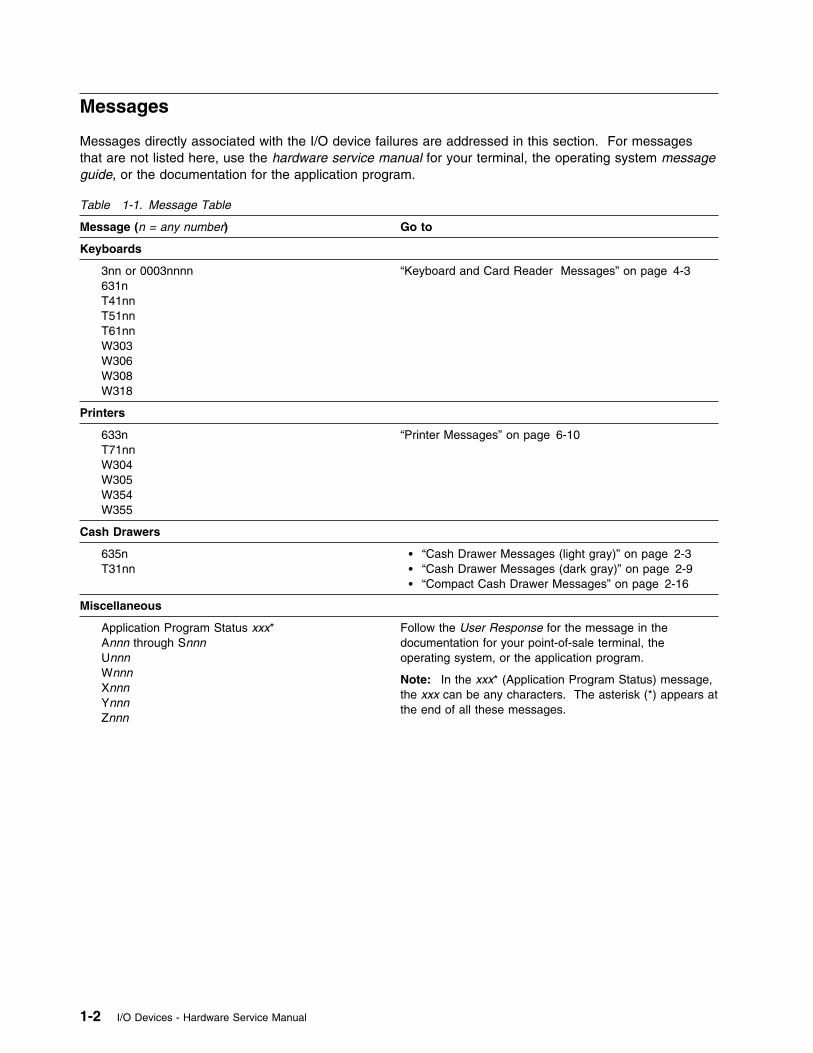
Messages directly associated with the I/O device failures are addressed in this section. For messagesthat are not listed here, use the hardware service manual for your terminal, the operating system messageguide, or the documentation for the application program.
Table 1-1. Message Table
Message (n = any number) Go to
Keyboards
3nn or 0003nnnn 631n T41nn T51nn T61nn W303 W306 W308 W318
“Keyboard and Card Reader Messages” on page 4-3
Printers
633n T71nn W304 W305 W354 W355
“Printer Messages” on page 6-10
Cash Drawers
635n T31nn
� “Cash Drawer Messages (light gray)” on page 2-3� “Cash Drawer Messages (dark gray)” on page 2-9� “Compact Cash Drawer Messages” on page 2-16
Miscellaneous
Application Program Status xxx*Annn through Snnn
Unnn Wnnn Xnnn Ynnn Znnn
Follow the User Response for the message in thedocumentation for your point-of-sale terminal, theoperating system, or the application program.
Note: In the xxx* (Application Program Status) message,the xxx can be any characters. The asterisk (*) appears atthe end of all these messages.
1-2 I/O Devices - Hardware Service Manual

Symptoms
Symptoms directly associated with the I/O devices are addressed in this section. The following tabledetermines where to look for symptom descriptions and required actions.
Table 1-2. Symptom Index
Symptom Go to
Cash drawer symptoms � “Point-of-Sale Cash Drawer (light gray)” on page 2-3� “Point-of-Sale Cash Drawer (dark gray)” on page 2-8� “Compact Cash Drawer Symptoms” on page 2-17
Display Chapter 3, “Point-of-Sale Displays” on page 3-1
Keyboard Chapter 4, “Point-of-Sale Keyboards” on page 4-1
Printer Chapter 5, “Point-of-Sale Printer Model 1 or Model 2” onpage 5-1 or Chapter 6, “Point-of-Sale Printer Models 3,3R, 4, 4A, 4R” on page 6-1
Signature capture device Chapter 7, “4678 OEM Input/Output Devices” on page 7-1
Miscellaneous Follow the User Response for the symptom in thehardware service manual for your terminal or in theoperating system problem determination guide.
Chapter 1. START 1-3

1-4 I/O Devices - Hardware Service Manual
Chapter 2. Point-Of-Sale Cash Drawers
This chapter contains repair information for servicing light gray, dark gray, and compact point-of-sale cashdrawers.
Note: It is assumed that you were directed to this manual from the hardware service manual or problemdetermination procedures for your terminal and that the failure has been isolated to the cash drawer orcable.
DANGER
Never work on equipment or connect or disconnect signal cables during periods oflightning activity.
CAUTION:For your safety, connect equipment requiring electrical power to a properly wired and groundedoutlet.
Electrostatic Discharge (ESD)
Attention ESD damage can occur when there is a difference in charge between the part, the product, andthe service person. No damage occurs if the service person and the part being installed are at the samecharge level.
ESD Damage Prevention
Anytime a service action involves physical contact with logic cards, modules, back-panel pins, or otherESD sensitive (ESDS) parts, the service person must be connected to an ESD common ground point onthe product through the ESD wrist strap and cord.
The ESD ground clip can be attached to any frame ground, ground braid, green wire ground, or the roundground prong on the AC power plug. Coax or connector outside shells can also be used.
Handling Removed Cards
Logic cards removed from a product should be placed in ESD protective containers. No other objectshould be allowed inside the ESD container with the logic card. Attach tags or reports that mustaccompany the card to the outside of the container. Point-of-Sale Cash Drawer (light gray) . . . . . . . . . . . . . . . . . . . . . . . . . . . . . . . . . . . . 2-3
Cash Drawer Messages (light gray) . . . . . . . . . . . . . . . . . . . . . . . . . . . . . . . . . . . . 2-3Cash Drawer Symptoms (light gray) . . . . . . . . . . . . . . . . . . . . . . . . . . . . . . . . . . . . 2-3Removing and Replacing the Drawer . . . . . . . . . . . . . . . . . . . . . . . . . . . . . . . . . . . . 2-4Removing and Replacing the Top Cover . . . . . . . . . . . . . . . . . . . . . . . . . . . . . . . . . . 2-5Removing and Replacing the Slide Assembly . . . . . . . . . . . . . . . . . . . . . . . . . . . . . . . 2-6Removing and Replacing the Latch and Sensor Assembly . . . . . . . . . . . . . . . . . . . . . . . 2-6Removing and Replacing the Cam . . . . . . . . . . . . . . . . . . . . . . . . . . . . . . . . . . . . . 2-7Removing and Replacing the Keylock Assembly . . . . . . . . . . . . . . . . . . . . . . . . . . . . . 2-8
Point-of-Sale Cash Drawer (dark gray) . . . . . . . . . . . . . . . . . . . . . . . . . . . . . . . . . . . . 2-8Cash Drawer Messages (dark gray) . . . . . . . . . . . . . . . . . . . . . . . . . . . . . . . . . . . . 2-9Cash Drawer Symptoms (dark gray) . . . . . . . . . . . . . . . . . . . . . . . . . . . . . . . . . . . . 2-9Removing and Replacing the Drawer . . . . . . . . . . . . . . . . . . . . . . . . . . . . . . . . . . . 2-11
Copyright IBM Corp. 1993, 1995 2-1
Removing and Replacing the Top Cover . . . . . . . . . . . . . . . . . . . . . . . . . . . . . . . . . 2-12Removing and Replacing the Slide Assembly . . . . . . . . . . . . . . . . . . . . . . . . . . . . . . 2-12Removing and Replacing the Latch Assembly . . . . . . . . . . . . . . . . . . . . . . . . . . . . . 2-13Removing and Replacing the Card Assembly . . . . . . . . . . . . . . . . . . . . . . . . . . . . . . 2-14Removing and Replacing the Cash Drawer Cam . . . . . . . . . . . . . . . . . . . . . . . . . . . . 2-14Removing and Replacing the Cash Drawer Pawl . . . . . . . . . . . . . . . . . . . . . . . . . . . . 2-14Removing and Replacing the Keylock Assembly . . . . . . . . . . . . . . . . . . . . . . . . . . . . 2-16
Compact Cash Drawer . . . . . . . . . . . . . . . . . . . . . . . . . . . . . . . . . . . . . . . . . . . . . 2-16Compact Cash Drawer Messages . . . . . . . . . . . . . . . . . . . . . . . . . . . . . . . . . . . . 2-16Compact Cash Drawer Symptoms . . . . . . . . . . . . . . . . . . . . . . . . . . . . . . . . . . . . 2-17Compact Cash Drawer Removals and Replacements . . . . . . . . . . . . . . . . . . . . . . . . . 2-19Removing and Replacing the Drawer . . . . . . . . . . . . . . . . . . . . . . . . . . . . . . . . . . . 2-19Removing and Replacing the Drawer Slide Latches . . . . . . . . . . . . . . . . . . . . . . . . . . 2-19Removing and Replacing the Slide Assembly . . . . . . . . . . . . . . . . . . . . . . . . . . . . . . 2-20Removing and Replacing the Rollers . . . . . . . . . . . . . . . . . . . . . . . . . . . . . . . . . . . 2-20Removing and Replacing the Keylock Assembly . . . . . . . . . . . . . . . . . . . . . . . . . . . . 2-21Removing and Replacing the Top Cover . . . . . . . . . . . . . . . . . . . . . . . . . . . . . . . . . 2-21Removing and Replacing the Latch and Sensor Assembly . . . . . . . . . . . . . . . . . . . . . . 2-21Removing and Replacing Latch and Sensor Assembly FRUs . . . . . . . . . . . . . . . . . . . . . 2-22Removing and Replacing the Coin Roll Cutter . . . . . . . . . . . . . . . . . . . . . . . . . . . . . 2-23Removing and Replacing the Compact Cash Drawer Security Clip . . . . . . . . . . . . . . . . . 2-24
Replacing the Compact Cash Drawer Integration Cover . . . . . . . . . . . . . . . . . . . . . . . . . 2-25
2-2 I/O Devices - Hardware Service Manual
Point-of-Sale Cash Drawer (light gray)
Cash Drawer Messages (light gray)
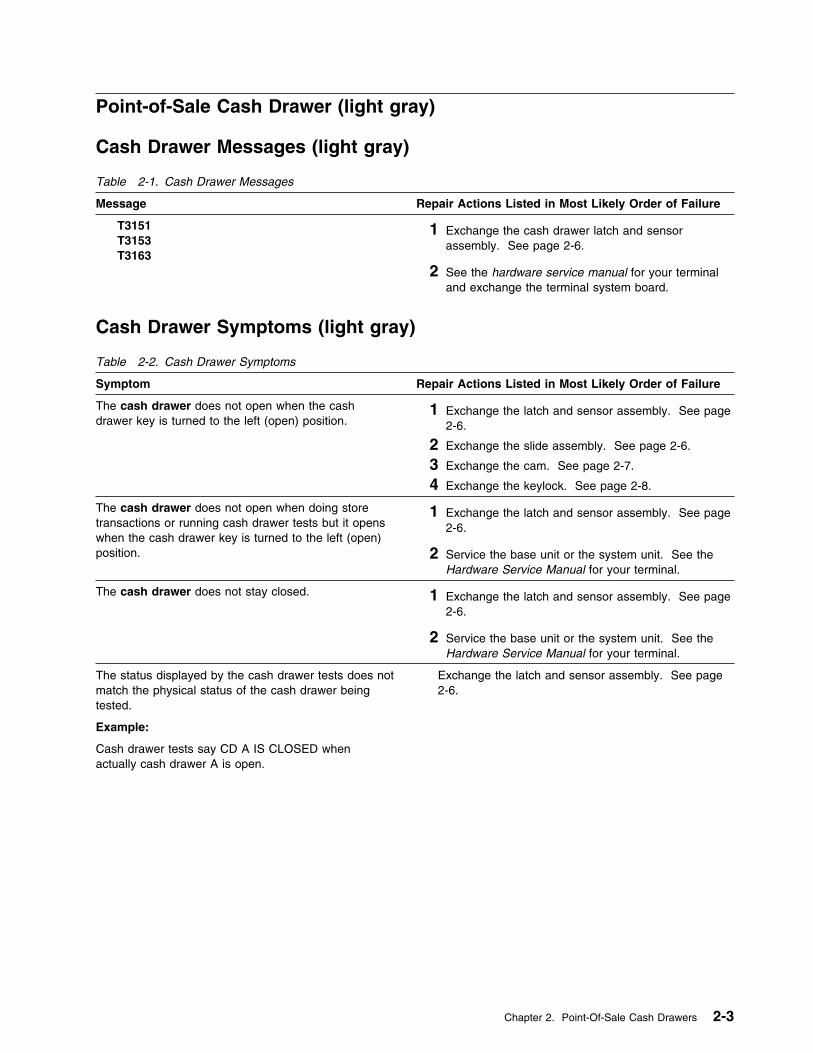
Table 2-1. Cash Drawer Messages
Message Repair Actions Listed in Most Likely Order of Failure
T3151 T3153 T3163
1 Exchange the cash drawer latch and sensorassembly. See page 2-6.
2 See the hardware service manual for your terminaland exchange the terminal system board.
Cash Drawer Symptoms (light gray)
Table 2-2. Cash Drawer Symptoms
Symptom Repair Actions Listed in Most Likely Order of Failure
The cash drawer does not open when the cashdrawer key is turned to the left (open) position.
1 Exchange the latch and sensor assembly. See page2-6.
2 Exchange the slide assembly. See page 2-6.
3 Exchange the cam. See page 2-7.
4 Exchange the keylock. See page 2-8.
The cash drawer does not open when doing storetransactions or running cash drawer tests but it openswhen the cash drawer key is turned to the left (open)position.
1 Exchange the latch and sensor assembly. See page2-6.
2 Service the base unit or the system unit. See theHardware Service Manual for your terminal.
The cash drawer does not stay closed. 1 Exchange the latch and sensor assembly. See page2-6.
2 Service the base unit or the system unit. See theHardware Service Manual for your terminal.
The status displayed by the cash drawer tests does notmatch the physical status of the cash drawer beingtested.
Example:
Cash drawer tests say CD A IS CLOSED whenactually cash drawer A is open.
Exchange the latch and sensor assembly. See page2-6.
Chapter 2. Point-Of-Sale Cash Drawers 2-3
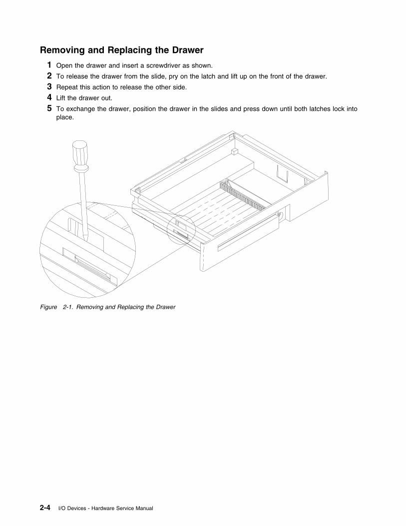
Removing and Replacing the Drawer
1 Open the drawer and insert a screwdriver as shown.
2 To release the drawer from the slide, pry on the latch and lift up on the front of the drawer.
3 Repeat this action to release the other side.
4 Lift the drawer out.
5 To exchange the drawer, position the drawer in the slides and press down until both latches lock intoplace.
Figure 2-1. Removing and Replacing the Drawer
2-4 I/O Devices - Hardware Service Manual
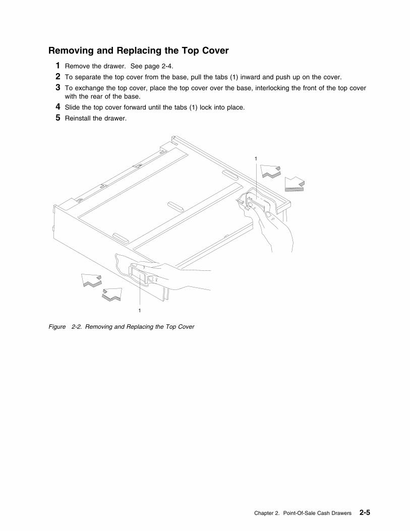
Removing and Replacing the Top Cover
1 Remove the drawer. See page 2-4.
2 To separate the top cover from the base, pull the tabs (1) inward and push up on the cover.
3 To exchange the top cover, place the top cover over the base, interlocking the front of the top coverwith the rear of the base.
4 Slide the top cover forward until the tabs (1) lock into place.
5 Reinstall the drawer.
1
1
Figure 2-2. Removing and Replacing the Top Cover
Chapter 2. Point-Of-Sale Cash Drawers 2-5
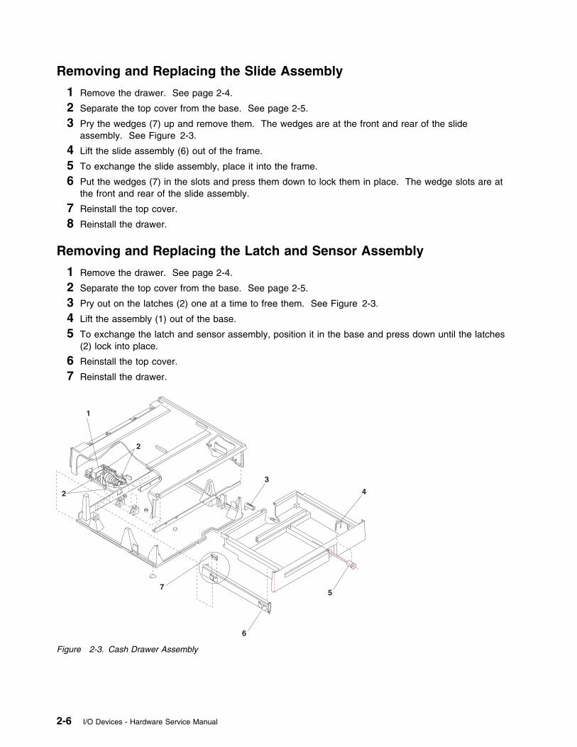
Removing and Replacing the Slide Assembly
1 Remove the drawer. See page 2-4.
2 Separate the top cover from the base. See page 2-5.
3 Pry the wedges (7) up and remove them. The wedges are at the front and rear of the slideassembly. See Figure 2-3.
4 Lift the slide assembly (6) out of the frame.
5 To exchange the slide assembly, place it into the frame.
6 Put the wedges (7) in the slots and press them down to lock them in place. The wedge slots are atthe front and rear of the slide assembly.
7 Reinstall the top cover.
8 Reinstall the drawer.
Removing and Replacing the Latch and Sensor Assembly
1 Remove the drawer. See page 2-4.
2 Separate the top cover from the base. See page 2-5.
3 Pry out on the latches (2) one at a time to free them. See Figure 2-3.
4 Lift the assembly (1) out of the base.
5 To exchange the latch and sensor assembly, position it in the base and press down until the latches(2) lock into place.
6 Reinstall the top cover.
7 Reinstall the drawer.
Figure 2-3. Cash Drawer Assembly
2-6 I/O Devices - Hardware Service Manual
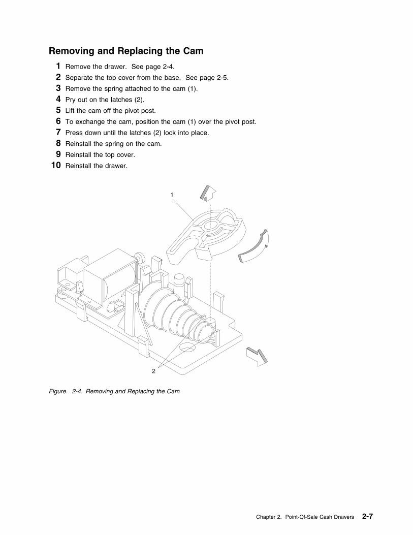
Removing and Replacing the Cam
1 Remove the drawer. See page 2-4.
2 Separate the top cover from the base. See page 2-5.
3 Remove the spring attached to the cam (1).
4 Pry out on the latches (2).
5 Lift the cam off the pivot post.
6 To exchange the cam, position the cam (1) over the pivot post.
7 Press down until the latches (2) lock into place.
8 Reinstall the spring on the cam.
9 Reinstall the top cover.
10 Reinstall the drawer.
1
2
Figure 2-4. Removing and Replacing the Cam
Chapter 2. Point-Of-Sale Cash Drawers 2-7

Removing and Replacing the Keylock Assembly
1 Remove the drawer. See page 2-4.
2 Release the latches (3) on both sides of the locking cam and remove the locking cam.
3 Remove the clip (4).
4 Slide the lock assembly out of the drawer.
5 To exchange the keylock assembly, slide the lock assembly into the drawer.
6 Reinstall the clip (4).
7 Push the locking cam onto the shaft until the latches (3) lock into place.
8 Reinstall the drawer.
Figure 2-5. Cash Drawer Assembly
Point-of-Sale Cash Drawer (dark gray)
This section contains the repair information for dark gray cash drawers.
2-8 I/O Devices - Hardware Service Manual
Cash Drawer Messages (dark gray)
Use the following table to determine the cause of a cash drawer message.
Table 2-3. Cash Drawer Messages
Message Repair Actions Listed in Most Likely Order of Failure
T3151 T3153 T3163
1 Exchange the latch and sensor assembly. See page2-13.
2 See the hardware service manual for your terminaland exchange the terminal system board.
Cash Drawer Symptoms (dark gray)
Use the following table to determine the cause of a cash drawer symptom.
Table 2-4 (Page 1 of 2). Cash Drawer Symptoms
Symptom Repair Actions Listed in Most Likely Order of Failure
The cash drawer does not open when the cashdrawer key is turned to the left (open) position.
1 Exchange the latch and sensor assembly. See page2-13.
2 Exchange the slide assembly. See page 2-12.
3 Exchange the cam. See page 2-14.
4 Exchange the keylock. See page 2-16.
The cash drawer does not open when doing storetransactions or running cash drawer tests but it openswhen the cash drawer key is turned to the left (open)position.
1 Exchange the latch and sensor assembly. See page2-13.
2 If this is a 4693 terminal, see the IBM 4693, 4694,and 4695 Point of Sale Terminals: HardwareService Manual, SY27-0337 and exchange the RearConnector Panel.
3 If this is a 4684 terminal, see the IBM 4683/4684Point of Sale Terminal: Maintenance Manual,SY27-0295 and exchange the Power Supply.
4 See the hardware service manual for your terminaland exchange the terminal system board.
The cash drawer does not stay closed. 1 Exchange the latch and sensor assembly. See page2-13.
2 Exchange the drawer. See page 2-11.
3 If this is a 4693 terminal, see the IBM 4693, 4694,and 4695 Point of Sale Terminals: HardwareService Manual, SY27-0337 and exchange the RearConnector Panel.
4 If this is a 4684 terminal, see the IBM 4683/4684Point of Sale Terminal: Maintenance Manual,SY27-0295 and exchange the Power Supply.
5 See the hardware service manual for your terminaland exchange the terminal system board.
Chapter 2. Point-Of-Sale Cash Drawers 2-9

Table 2-4 (Page 2 of 2). Cash Drawer Symptoms
Symptom Repair Actions Listed in Most Likely Order of Failure
The status displayed by the cash drawer tests does notmatch the physical status of the cash drawer beingtested.
Example:
Cash drawer tests say CD A IS CLOSED whenactually cash drawer A is open.
Exchange the latch and sensor assembly. See page 2-13.
2-10 I/O Devices - Hardware Service Manual
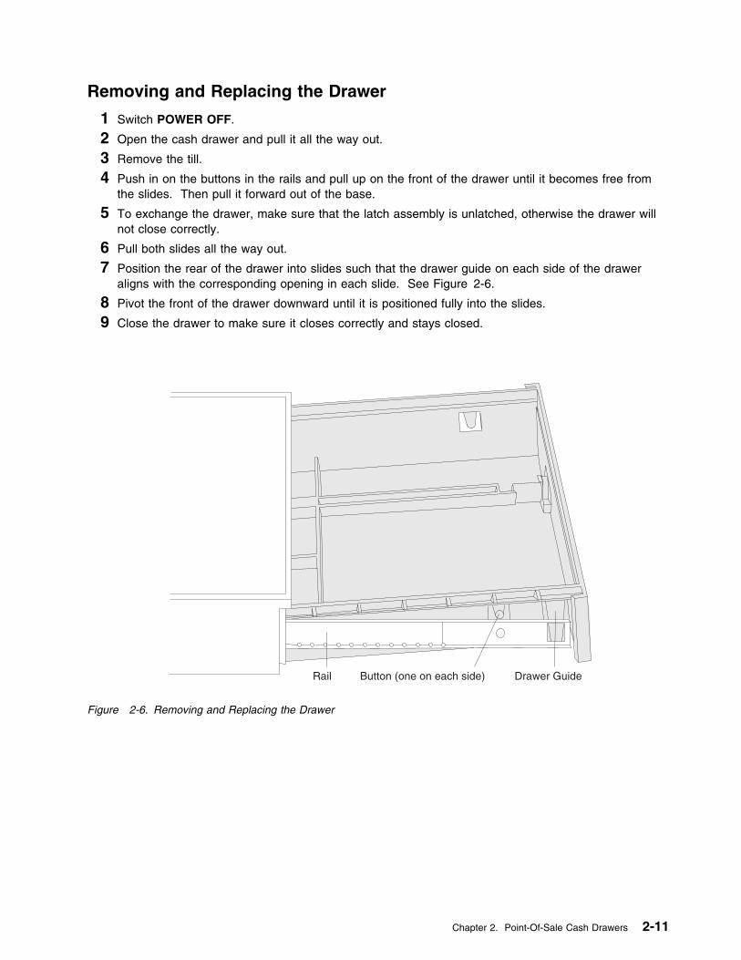
Removing and Replacing the Drawer
1 Switch POWER OFF.
2 Open the cash drawer and pull it all the way out.
3 Remove the till.
4 Push in on the buttons in the rails and pull up on the front of the drawer until it becomes free fromthe slides. Then pull it forward out of the base.
5 To exchange the drawer, make sure that the latch assembly is unlatched, otherwise the drawer willnot close correctly.
6 Pull both slides all the way out.
7 Position the rear of the drawer into slides such that the drawer guide on each side of the draweraligns with the corresponding opening in each slide. See Figure 2-6.
8 Pivot the front of the drawer downward until it is positioned fully into the slides.
9 Close the drawer to make sure it closes correctly and stays closed.
Rail Button (one on each side) Drawer Guide
Figure 2-6. Removing and Replacing the Drawer
Chapter 2. Point-Of-Sale Cash Drawers 2-11
Removing and Replacing the Top Cover
1 Switch POWER OFF.
2 Open the rear panel by pushing the buttons at the upper rear corners of the cover.
3 Disconnect the cash drawer cable from the rear of the cash drawer.
Note: There may be other terminal cables routed through the rear of the top cover. Remove therear panel by releasing it at the pivots. Separate the top cover and base without disturbing thesecables. Only disconnect cables from the terminal unit when necessary.
4 Set the devices mounted on the top cover to the side.
5 Remove the drawer. See page 2-11.
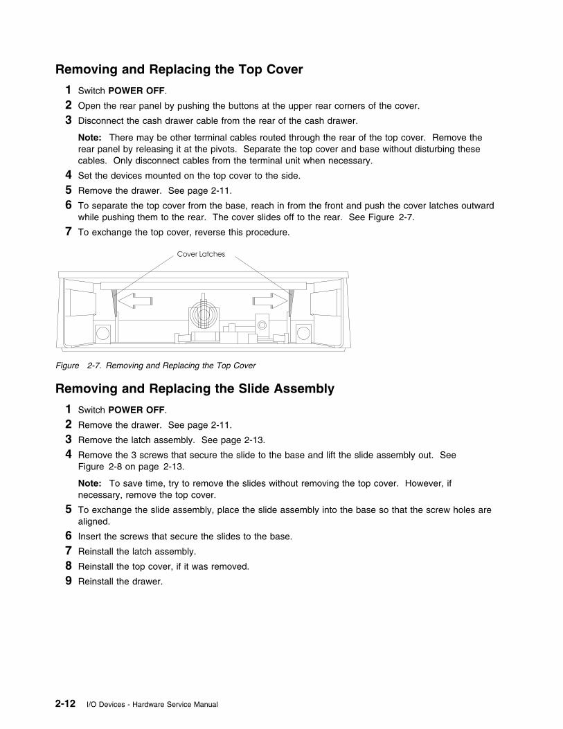
6 To separate the top cover from the base, reach in from the front and push the cover latches outwardwhile pushing them to the rear. The cover slides off to the rear. See Figure 2-7.
7 To exchange the top cover, reverse this procedure.
Cover Latches
Figure 2-7. Removing and Replacing the Top Cover
Removing and Replacing the Slide Assembly
1 Switch POWER OFF.
2 Remove the drawer. See page 2-11.
3 Remove the latch assembly. See page 2-13.
4 Remove the 3 screws that secure the slide to the base and lift the slide assembly out. SeeFigure 2-8 on page 2-13.
Note: To save time, try to remove the slides without removing the top cover. However, ifnecessary, remove the top cover.
5 To exchange the slide assembly, place the slide assembly into the base so that the screw holes arealigned.
6 Insert the screws that secure the slides to the base.
7 Reinstall the latch assembly.
8 Reinstall the top cover, if it was removed.
9 Reinstall the drawer.
2-12 I/O Devices - Hardware Service Manual

Removing and Replacing the Latch Assembly
1 Switch POWER OFF.
2 Disconnect the cash drawer cable from the connector at the rear of the cash drawer.
3 Remove the drawer. See page 2-11.
4 Reach in from the front and push the latch on each side of the latch assembly inward while pullingthe assembly toward the front. See Figure 2-8.
5 Slide the assembly out of the base.
6 To exchange the latch assembly, slide the assembly into the base from the front and align it with theslots in the base. Push the assembly to the rear until it locks into place.
7 Make sure the latching mechanism is unlatched.
8 Reinstall the drawer.
9 Reconnect the cash drawer cable to the connector at the rear.
Latch Assembly Latches
Slide Assembly Screws
Figure 2-8. Removing and Replacing the Slide Assembly
Chapter 2. Point-Of-Sale Cash Drawers 2-13

Removing and Replacing the Card Assembly
1 Switch POWER OFF.
2 Remove the drawer. See page 2-11.
3 Remove the latch assembly. See page 2-13.
4 Remove the pawl. See page 2-14 and 2-15.
5 Remove the 3 screws holding the card assembly to the latch assembly.
6 To exchange the card assembly, position the card assembly on the latch assembly and secure it withthe 3 screws.
7 Reinstall the pawl. Make sure that the latch assembly is in the unlatched position.
8 Reinstall the latch assembly.
9 Reinstall the drawer.
Removing and Replacing the Cash Drawer Cam
1 Switch POWER OFF.
2 Remove the drawer. See page 2-11.
3 Remove the latch assembly. See page 2-13.
4 Remove the cash drawer propulsion spring by pushing the spring retainer and sliding the spring upout of its mounting slots. See Figure 2-9 on page 2-15.
5 Remove the cam spring.
6 Spread apart the 2 cam latches holding the cam on the pivot post while lifting the cam off the post.
7 To exchange the cam assembly, position the cam over the pivot post and push down until the camlatches lock the cam into place.
8 Attach the cam spring to the cam and to the pawl. Make sure that the latch assembly is in theunlatched position.
9 Reinstall the cash drawer propulsion spring.
10 Reinstall the latch assembly.
11 Reinstall the drawer.
Removing and Replacing the Cash Drawer Pawl
1 Switch POWER OFF.
2 Remove the drawer. See page 2-11.
3 Remove the latch assembly. See page 2-13.
4 Remove the cam spring. See Figure 2-9 on page 2-15.
5 Spread apart the 2 pawl latches holding the pawl on the pivot post while lifting the pawl off the post.
6 To exchange the pawl assembly, position the pawl over the pivot post and push down until the pawllatch locks the pawl into place.
7 Attach the cam spring to the cam and to the pawl. Make sure that the latch assembly is in theunlatched position.
8 Reinstall the latch assembly.
9 Reinstall the drawer.
2-14 I/O Devices - Hardware Service Manual
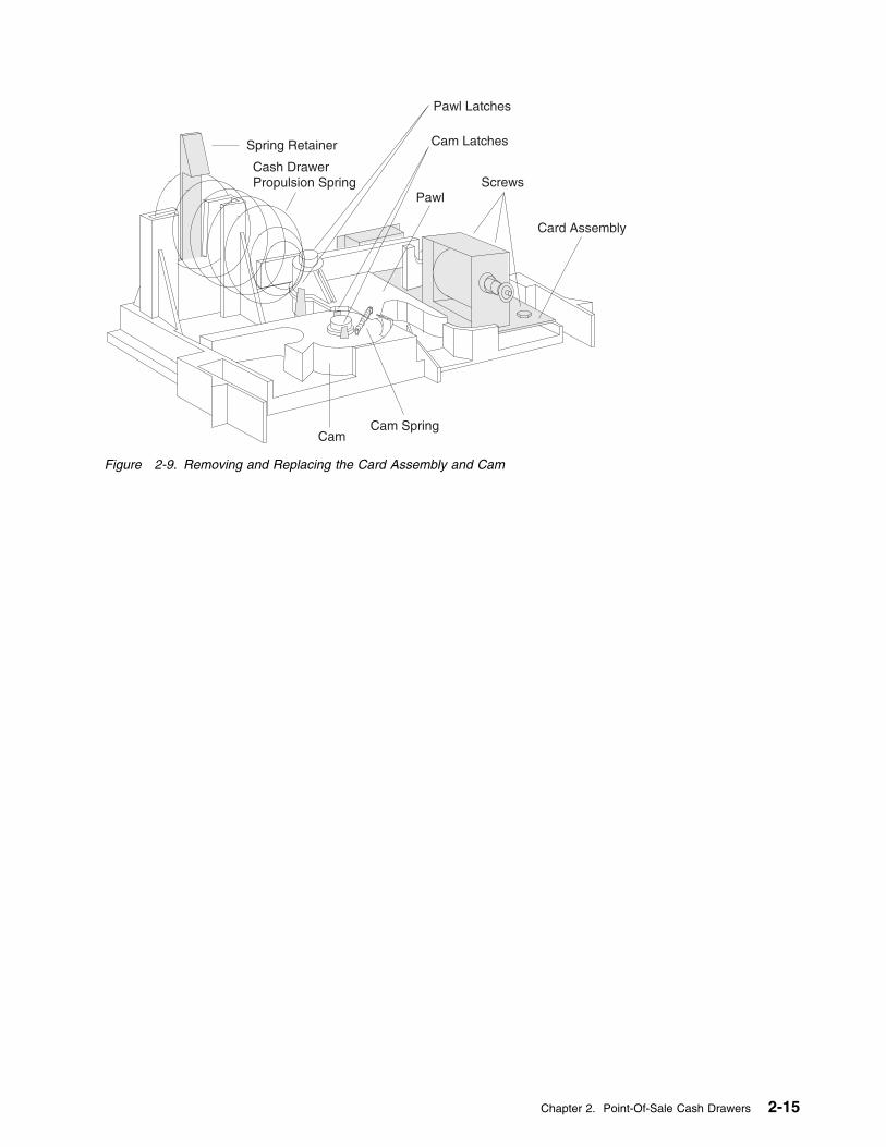
Spring Retainer
Cash DrawerPropulsion Spring
Pawl Latches
Cam Latches
PawlScrews
Card Assembly
Cam SpringCam
Figure 2-9. Removing and Replacing the Card Assembly and Cam
Chapter 2. Point-Of-Sale Cash Drawers 2-15
Removing and Replacing the Keylock Assembly
1 Remove the drawer. See page 2-11.
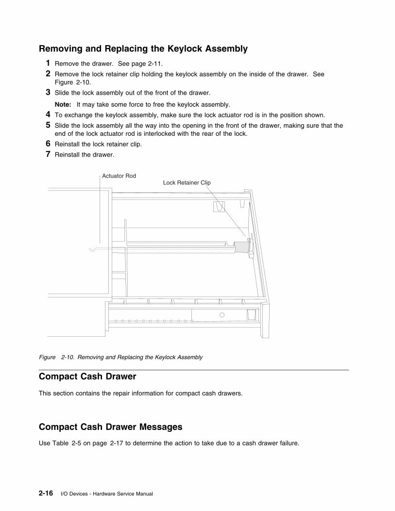
2 Remove the lock retainer clip holding the keylock assembly on the inside of the drawer. SeeFigure 2-10.
3 Slide the lock assembly out of the front of the drawer.
Note: It may take some force to free the keylock assembly.
4 To exchange the keylock assembly, make sure the lock actuator rod is in the position shown.
5 Slide the lock assembly all the way into the opening in the front of the drawer, making sure that theend of the lock actuator rod is interlocked with the rear of the lock.
6 Reinstall the lock retainer clip.
7 Reinstall the drawer.
Actuator RodLock Retainer Clip
Figure 2-10. Removing and Replacing the Keylock Assembly
Compact Cash Drawer
This section contains the repair information for compact cash drawers.
Compact Cash Drawer Messages
Use Table 2-5 on page 2-17 to determine the action to take due to a cash drawer failure.
2-16 I/O Devices - Hardware Service Manual
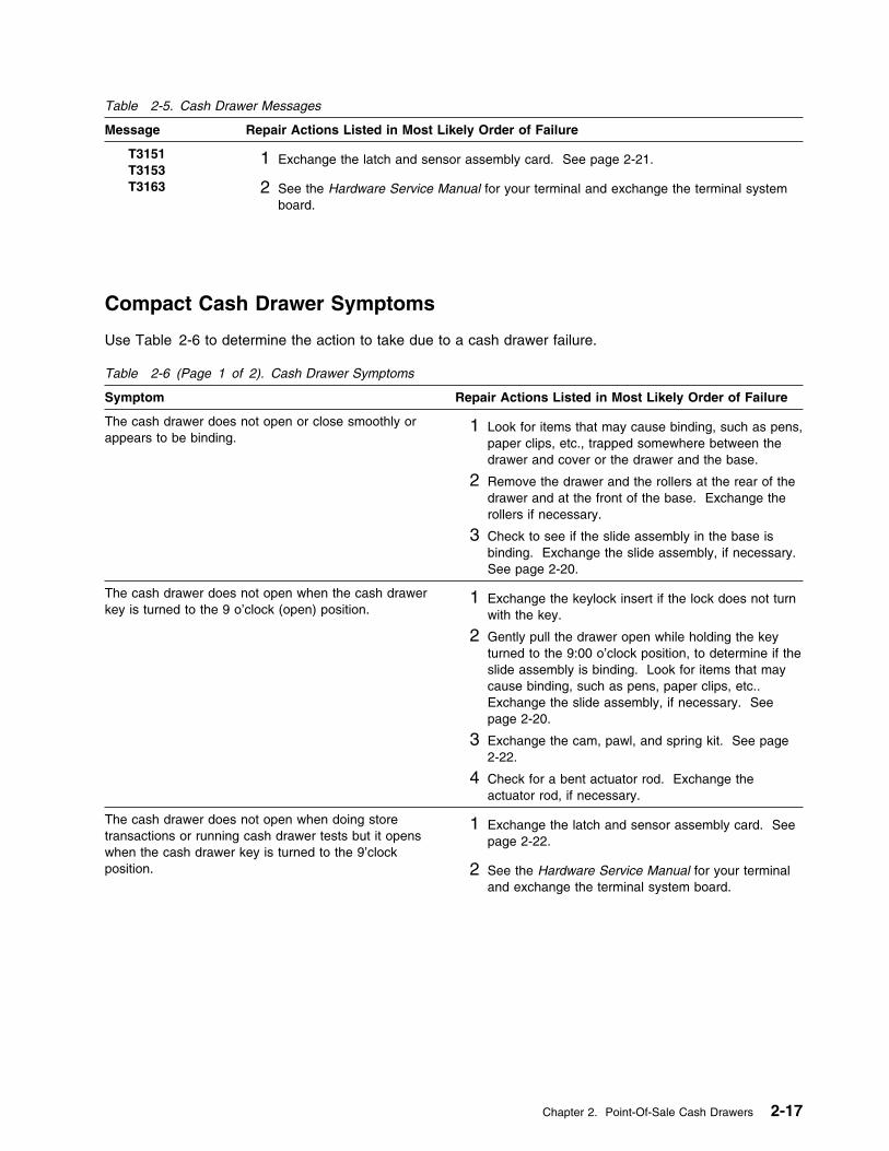
Table 2-5. Cash Drawer Messages
Message Repair Actions Listed in Most Likely Order of Failure
T3151 T3153 T3163
1 Exchange the latch and sensor assembly card. See page 2-21.
2 See the Hardware Service Manual for your terminal and exchange the terminal systemboard.
Compact Cash Drawer Symptoms
Use Table 2-6 to determine the action to take due to a cash drawer failure.
Table 2-6 (Page 1 of 2). Cash Drawer Symptoms
Symptom Repair Actions Listed in Most Likely Order of Failure
The cash drawer does not open or close smoothly orappears to be binding.
1 Look for items that may cause binding, such as pens,paper clips, etc., trapped somewhere between thedrawer and cover or the drawer and the base.
2 Remove the drawer and the rollers at the rear of thedrawer and at the front of the base. Exchange therollers if necessary.
3 Check to see if the slide assembly in the base isbinding. Exchange the slide assembly, if necessary.See page 2-20.
The cash drawer does not open when the cash drawerkey is turned to the 9 o’clock (open) position.
1 Exchange the keylock insert if the lock does not turnwith the key.
2 Gently pull the drawer open while holding the keyturned to the 9:00 o’clock position, to determine if theslide assembly is binding. Look for items that maycause binding, such as pens, paper clips, etc..Exchange the slide assembly, if necessary. Seepage 2-20.
3 Exchange the cam, pawl, and spring kit. See page2-22.
4 Check for a bent actuator rod. Exchange theactuator rod, if necessary.
The cash drawer does not open when doing storetransactions or running cash drawer tests but it openswhen the cash drawer key is turned to the 9’clockposition.
1 Exchange the latch and sensor assembly card. Seepage 2-22.
2 See the Hardware Service Manual for your terminaland exchange the terminal system board.
Chapter 2. Point-Of-Sale Cash Drawers 2-17
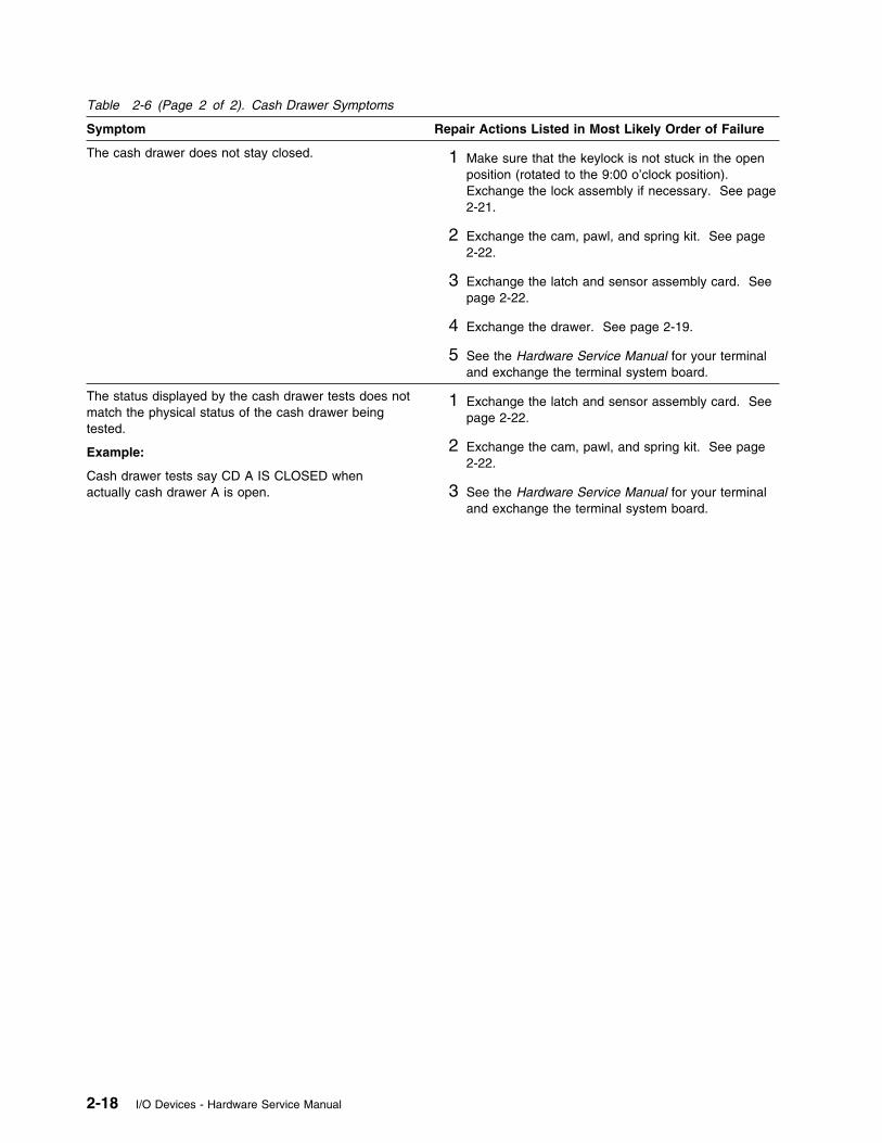
Table 2-6 (Page 2 of 2). Cash Drawer Symptoms
Symptom Repair Actions Listed in Most Likely Order of Failure
The cash drawer does not stay closed. 1 Make sure that the keylock is not stuck in the openposition (rotated to the 9:00 o’clock position).Exchange the lock assembly if necessary. See page2-21.
2 Exchange the cam, pawl, and spring kit. See page2-22.
3 Exchange the latch and sensor assembly card. Seepage 2-22.
4 Exchange the drawer. See page 2-19.
5 See the Hardware Service Manual for your terminaland exchange the terminal system board.
The status displayed by the cash drawer tests does notmatch the physical status of the cash drawer beingtested.
Example:
Cash drawer tests say CD A IS CLOSED whenactually cash drawer A is open.
1 Exchange the latch and sensor assembly card. Seepage 2-22.
2 Exchange the cam, pawl, and spring kit. See page2-22.
3 See the Hardware Service Manual for your terminaland exchange the terminal system board.
2-18 I/O Devices - Hardware Service Manual
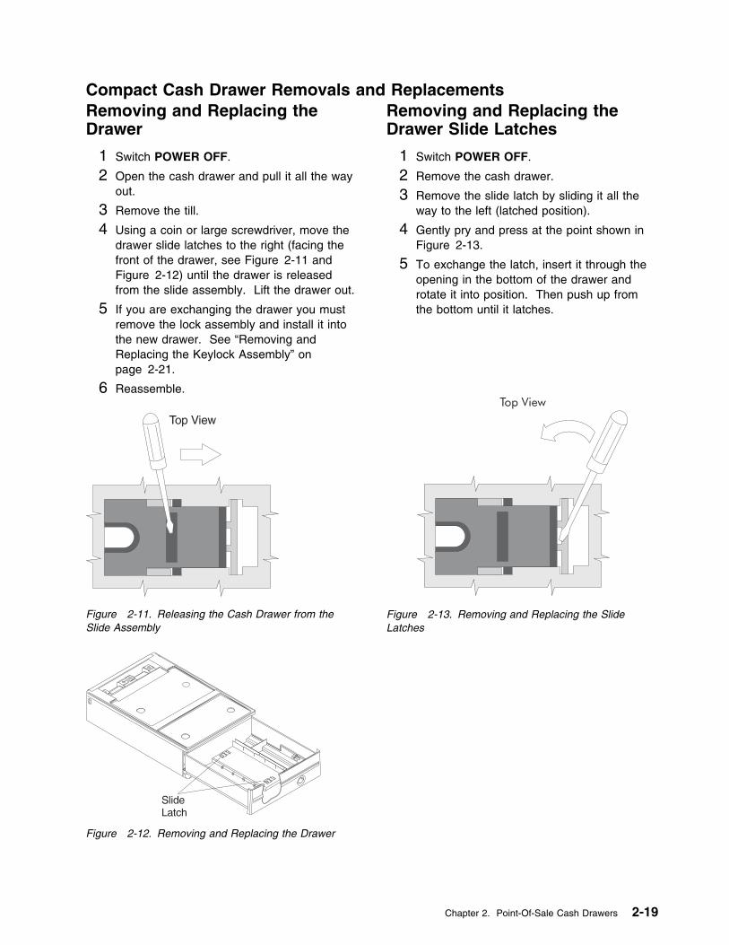
Compact Cash Drawer Removals and ReplacementsRemoving and Replacing theDrawer
1 Switch POWER OFF.
2 Open the cash drawer and pull it all the wayout.
3 Remove the till.
4 Using a coin or large screwdriver, move thedrawer slide latches to the right (facing thefront of the drawer, see Figure 2-11 andFigure 2-12) until the drawer is releasedfrom the slide assembly. Lift the drawer out.
5 If you are exchanging the drawer you mustremove the lock assembly and install it intothe new drawer. See “Removing andReplacing the Keylock Assembly” onpage 2-21.
6 Reassemble.
Figure 2-11. Releasing the Cash Drawer from theSlide Assembly
Figure 2-12. Removing and Replacing the Drawer
Removing and Replacing theDrawer Slide Latches
1 Switch POWER OFF.
2 Remove the cash drawer.
3 Remove the slide latch by sliding it all theway to the left (latched position).
4 Gently pry and press at the point shown inFigure 2-13.
5 To exchange the latch, insert it through theopening in the bottom of the drawer androtate it into position. Then push up fromthe bottom until it latches.
Figure 2-13. Removing and Replacing the SlideLatches
Chapter 2. Point-Of-Sale Cash Drawers 2-19
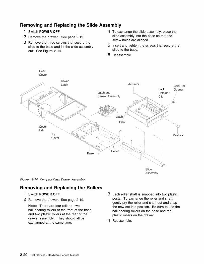
Removing and Replacing the Slide Assembly1 Switch POWER OFF.
2 Remove the drawer. See page 2-19.
3 Remove the three screws that secure theslide to the base and lift the slide assemblyout. See Figure 2-14.
4 To exchange the slide assembly, place theslide assembly into the base so that thescrew holes are aligned.
5 Insert and tighten the screws that secure theslide to the base.
6 Reassemble.
Figure 2-14. Compact Cash Drawer Assembly
Removing and Replacing the Rollers1 Switch POWER OFF.
2 Remove the drawer. See page 2-19.
Note: There are four rollers: twoball-bearing rollers at the front of the baseand two plastic rollers at the rear of thedrawer assembly. They should all beexchanged at the same time.
3 Each roller shaft is snapped into two plasticposts. To exchange the roller and shaft,gently pry the roller and shaft out and snapthe new set into position. Be sure to use theball bearing rollers on the base and theplastic rollers on the drawer.
4 Reassemble.
2-20 I/O Devices - Hardware Service Manual
Removing and Replacing theKeylock Assembly
1 Remove the drawer. See page 2-19.
2 Remove the lock retainer clip holding thekeylock assembly on the inside of thedrawer. See Figure 2-14 on page 2-20.
3 Slide the lock assembly out of the front ofthe drawer.
Note: It may take some force to free thekeylock assembly.
4 To exchange the keylock assembly, makesure the lock actuator rod is in the positionshown in Figure 2-14 on page 2-20.
5 Slide the lock assembly all the way into theopening in the front of the drawer, makingsure that the end of the lock actuator rod isinterlocked with the rear of the lock.
6 Reassemble.
Removing and Replacing the TopCover
1 Switch POWER OFF.
2 Remove any equipment that is on the top ofthe cash drawer.
3 Remove the rear cover.
4 Unplug cable 3 from the rear of the cashdrawer.
5 Remove the drawer. See page 2-19.
6 Reach into the front with two hands andpush the two cover latches to the outsidewhile sliding the top cover to the rear. SeeFigure 2-14 on page 2-20.
7 To exchange the top cover, align the topcover with the edges on the base at the rearand slide the cover forward until it latchesinto place.
8 Reassemble.
Removing and Replacing theLatch and Sensor Assembly
1 Switch POWER OFF.
2 Open the rear cover.
3 Disconnect the cash drawer cable fromconnector 3 at the rear of the cash drawer.
4 Remove the cash drawer. See page 2-19.
5 Reach in from the front with two hands andpush the latch on each side of the latchassembly inward while pulling the assemblytoward the front. See Figure 2-14 onpage 2-20.
6 To exchange the latch and sensor assembly,make sure the latching mechanism is in theunlatched (drawer open) position.
7 Slide the assembly into the base from thefront and align it with the slots in the base.Then push the assembly to the rear until itlocks into place.
8 Reassemble.
Chapter 2. Point-Of-Sale Cash Drawers 2-21
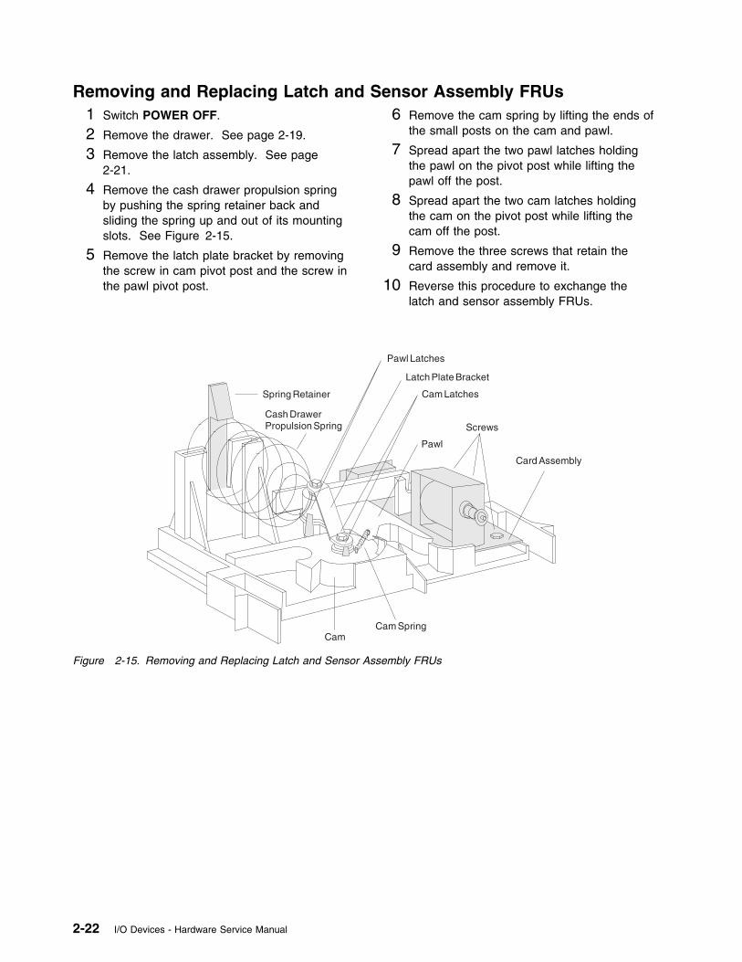
Removing and Replacing Latch and Sensor Assembly FRUs1 Switch POWER OFF.
2 Remove the drawer. See page 2-19.
3 Remove the latch assembly. See page2-21.
4 Remove the cash drawer propulsion springby pushing the spring retainer back andsliding the spring up and out of its mountingslots. See Figure 2-15.
5 Remove the latch plate bracket by removingthe screw in cam pivot post and the screw inthe pawl pivot post.
6 Remove the cam spring by lifting the ends ofthe small posts on the cam and pawl.
7 Spread apart the two pawl latches holdingthe pawl on the pivot post while lifting thepawl off the post.
8 Spread apart the two cam latches holdingthe cam on the pivot post while lifting thecam off the post.
9 Remove the three screws that retain thecard assembly and remove it.
10 Reverse this procedure to exchange thelatch and sensor assembly FRUs.
Screws
Cam Latches
Pawl Latches
Latch Plate Bracket
Spring Retainer
Cash DrawerPropulsion Spring
CamCam Spring
Pawl
Card Assembly
Figure 2-15. Removing and Replacing Latch and Sensor Assembly FRUs
2-22 I/O Devices - Hardware Service Manual
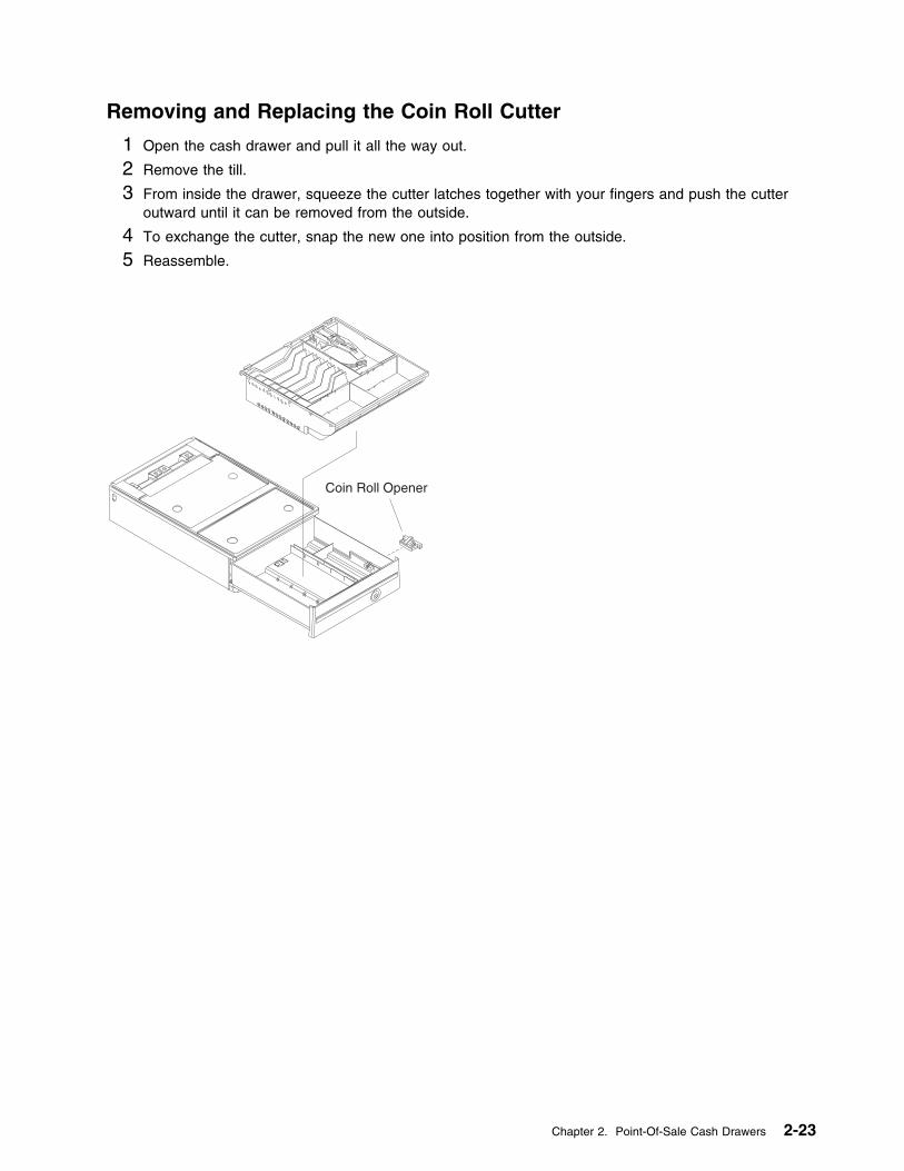
Removing and Replacing the Coin Roll Cutter
1 Open the cash drawer and pull it all the way out.
2 Remove the till.
3 From inside the drawer, squeeze the cutter latches together with your fingers and push the cutteroutward until it can be removed from the outside.
4 To exchange the cutter, snap the new one into position from the outside.
5 Reassemble.
Coin Roll Opener
Chapter 2. Point-Of-Sale Cash Drawers 2-23
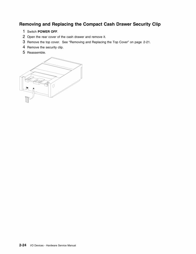
Removing and Replacing the Compact Cash Drawer Security Clip
1 Switch POWER OFF.
2 Open the rear cover of the cash drawer and remove it.
3 Remove the top cover. See “Removing and Replacing the Top Cover” on page 2-21.
4 Remove the security clip.
5 Reassemble.
2-24 I/O Devices - Hardware Service Manual
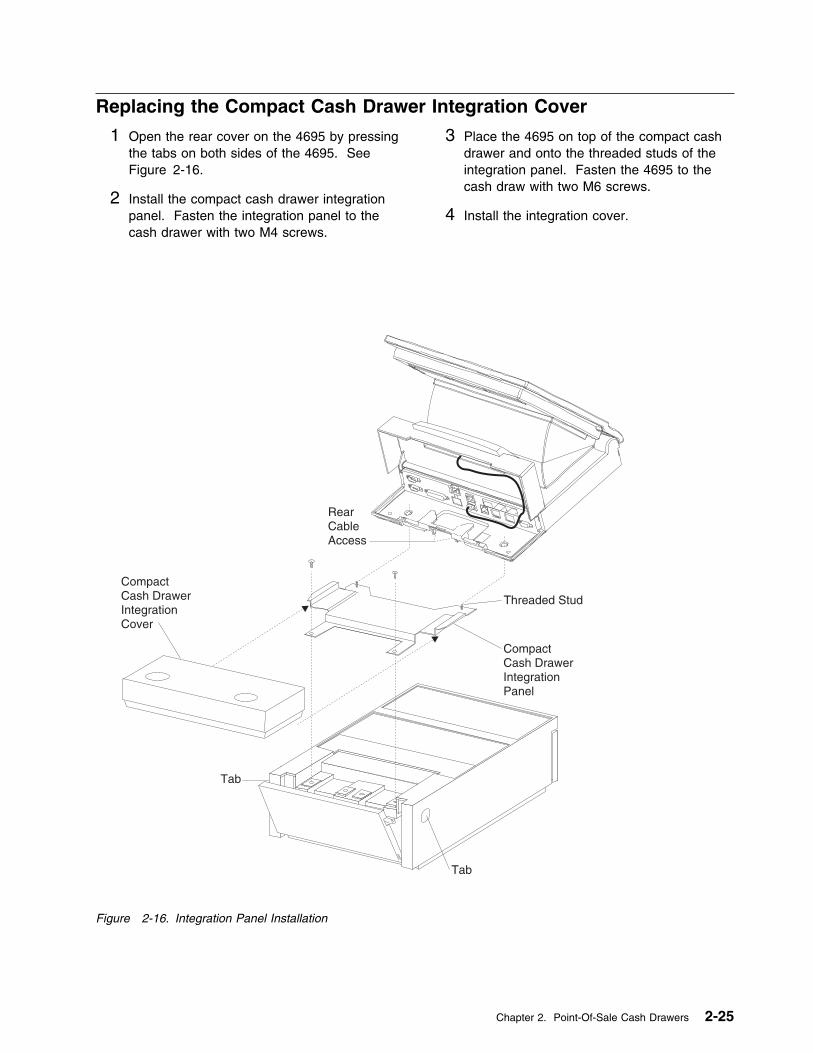
Replacing the Compact Cash Drawer Integration Cover
1 Open the rear cover on the 4695 by pressingthe tabs on both sides of the 4695. SeeFigure 2-16.
2 Install the compact cash drawer integrationpanel. Fasten the integration panel to thecash drawer with two M4 screws.
3 Place the 4695 on top of the compact cashdrawer and onto the threaded studs of theintegration panel. Fasten the 4695 to thecash draw with two M6 screws.
4 Install the integration cover.
Tab
Tab
RearCableAccess
CompactCash DrawerIntegrationPanel
Threaded Stud
CompactCash DrawerIntegrationCover
Figure 2-16. Integration Panel Installation
Chapter 2. Point-Of-Sale Cash Drawers 2-25

2-26 I/O Devices - Hardware Service Manual
Chapter 3. Point-of-Sale Displays
Flat Panel Display . . . . . . . . . . . . . . . . . . . . . . . . . . . . . . . . . . . . . . . . . . . . . . . . 3-2Flat Panel Display Testing . . . . . . . . . . . . . . . . . . . . . . . . . . . . . . . . . . . . . . . . . . 3-2Flat Panel Display Messages . . . . . . . . . . . . . . . . . . . . . . . . . . . . . . . . . . . . . . . . 3-3Flat Panel Display Sleep Control . . . . . . . . . . . . . . . . . . . . . . . . . . . . . . . . . . . . . . 3-4
Flat Panel Display Symptoms . . . . . . . . . . . . . . . . . . . . . . . . . . . . . . . . . . . . . . . . . . 3-5Flat Panel Display Component Removal and Replacement . . . . . . . . . . . . . . . . . . . . . . . . 3-6
Removing and Replacing the Front Cover . . . . . . . . . . . . . . . . . . . . . . . . . . . . . . . 3-6Removing and Replacing the LCD module Assembly . . . . . . . . . . . . . . . . . . . . . . . . . 3-6Removing and Replacing the CCFL (Cold Cathode Fluorescent Lamp) Assembly . . . . . . . . 3-7Removing and Replacing the LCD panel card . . . . . . . . . . . . . . . . . . . . . . . . . . . . . 3-7
Removing and Replacing the Flat Filler Panel . . . . . . . . . . . . . . . . . . . . . . . . . . . . . . 3-8Removing and Replacing the Display Cable . . . . . . . . . . . . . . . . . . . . . . . . . . . . . . . . 3-8
Sure Point Touch Screens . . . . . . . . . . . . . . . . . . . . . . . . . . . . . . . . . . . . . . . . . . . 3-8Touch Display Controls . . . . . . . . . . . . . . . . . . . . . . . . . . . . . . . . . . . . . . . . . . . . 3-8Touch Display Beeper Controls . . . . . . . . . . . . . . . . . . . . . . . . . . . . . . . . . . . . . . . 3-8Touch Display Calibration . . . . . . . . . . . . . . . . . . . . . . . . . . . . . . . . . . . . . . . . . . 3-9Touch Display Sleep Control . . . . . . . . . . . . . . . . . . . . . . . . . . . . . . . . . . . . . . . 3-10
Touch Display Symptoms . . . . . . . . . . . . . . . . . . . . . . . . . . . . . . . . . . . . . . . . . . . 3-11Touch Display Testing . . . . . . . . . . . . . . . . . . . . . . . . . . . . . . . . . . . . . . . . . . . 3-12Touch Display Messages . . . . . . . . . . . . . . . . . . . . . . . . . . . . . . . . . . . . . . . . . . 3-12
Monochrome Touch Display Component Removal and Replacement . . . . . . . . . . . . . . . . . . 3-13Removing and Replacing the Front Cover . . . . . . . . . . . . . . . . . . . . . . . . . . . . . . 3-13Removing and Replacing the LCD Module Assembly and Touch Panel Assembly . . . . . . . 3-13Removing and Replacing the CCFL (Cold Cathode Fluorescent Lamp) Assembly . . . . . . . 3-14Removing and Replacing the LCD Panel Card . . . . . . . . . . . . . . . . . . . . . . . . . . . 3-14
Color Touch Display Component Removal and Replacement . . . . . . . . . . . . . . . . . . . . . . 3-15Removing and Replacing the Front Cover . . . . . . . . . . . . . . . . . . . . . . . . . . . . . . . . 3-15Removing and Replacing the LCD Module Assembly and Touch Panel Assembly . . . . . . . . 3-16Removing and Replacing the CCFL (Cold Cathode Fluorescent Lamp) Assembly . . . . . . . . . 3-17Removing and Replacing the LCD Panel Card . . . . . . . . . . . . . . . . . . . . . . . . . . . . . 3-17Removing and Replacing the Inverter Card . . . . . . . . . . . . . . . . . . . . . . . . . . . . . . . 3-18
Removing and Replacing the Accessory Kits . . . . . . . . . . . . . . . . . . . . . . . . . . . . . . . . 3-19Removing and Replacing the Distribution Kit . . . . . . . . . . . . . . . . . . . . . . . . . . . . . . 3-19Removing and Replacing the Integration Kit . . . . . . . . . . . . . . . . . . . . . . . . . . . . . . . 3-20
Removing the Integration Kit . . . . . . . . . . . . . . . . . . . . . . . . . . . . . . . . . . . . . . 3-20Replacing the Integration Kit . . . . . . . . . . . . . . . . . . . . . . . . . . . . . . . . . . . . . . 3-20
40-Character Vacuum Fluorescent Display II . . . . . . . . . . . . . . . . . . . . . . . . . . . . . . . 3-23Removing and Replacing the 40-Character VFD II . . . . . . . . . . . . . . . . . . . . . . . . . . 3-23Removing, Replacing, and Cleaning the 40-Character Vacuum Fluorescent Display II Lens . . 3-23
40-Character Alphanumeric Display . . . . . . . . . . . . . . . . . . . . . . . . . . . . . . . . . . . . . 3-24Removing and Replacing the 40-Character VFD . . . . . . . . . . . . . . . . . . . . . . . . . . . . 3-24Removing, Replacing, and Cleaning the 40-Character Vacuum Fluorescent Display Lens . . . . 3-24
Copyright IBM Corp. 1993, 1995 3-1
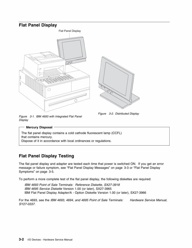
Flat Panel Display
Figure 3-1. IBM 4693 with Integrated Flat PanelDisplay
Figure 3-2. Distributed Display
Mercury Disposal
The flat panel display contains a cold cathode fluorescent lamp (CCFL)that contains mercury.Dispose of it in accordance with local ordinances or regulations.
Flat Panel Display Testing
The flat panel display and adapter are tested each time that power is switched ON. If you get an errormessage or failure symptom, see “Flat Panel Display Messages” on page 3-3 or “Flat Panel DisplaySymptoms” on page 3-5.
To perform a more complete test of the flat panel display, the following diskettes are required:
IBM 4693 Point of Sale Terminals: Reference Diskette, SX27-3918IBM 4695 Service Diskette Version 1.00 (or later), SX27-3965IBM Flat Panel Display Adapter/A - Option Diskette Version 1.00 (or later), SX27-3966
For the 4693, see the IBM 4693, 4694, and 4695 Point of Sale Terminals: Hardware Service Manual,SY27-0337.
3-2 I/O Devices - Hardware Service Manual

Flat Panel Display Messages
When the Mode Control Switch is pressed to switch Ready mode ON and storage retention is disabled,power-on self-test (POST) on the flat panel adapter is performed automatically. These messages indicateerrors detected by POST.
0148nnxn
Explanation: An IBM 4695 Point of Sale Adapter/A or IBM Flat Panel Display Adapter/A erroroccurred.(n = any number)(x = slot number)
User Response: Exchange the adapter card.
Chapter 3. Point-of-Sale Displays 3-3
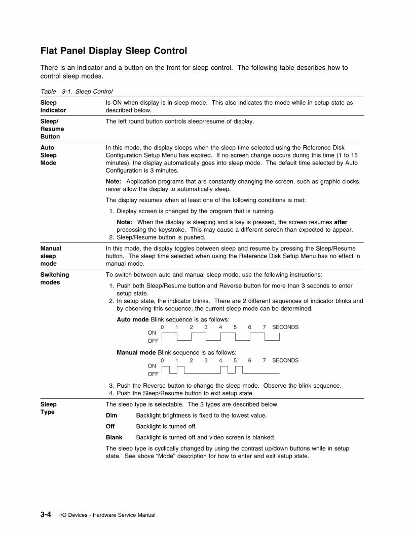
Flat Panel Display Sleep Control
There is an indicator and a button on the front for sleep control. The following table describes how tocontrol sleep modes.
Table 3-1. Sleep Control
SleepIndicator
Is ON when display is in sleep mode. This also indicates the mode while in setup state asdescribed below.
Sleep/ResumeButton
The left round button controls sleep/resume of display.
AutoSleepMode
In this mode, the display sleeps when the sleep time selected using the Reference DiskConfiguration Setup Menu has expired. If no screen change occurs during this time (1 to 15minutes), the display automatically goes into sleep mode. The default time selected by AutoConfiguration is 3 minutes.
Note: Application programs that are constantly changing the screen, such as graphic clocks,never allow the display to automatically sleep.
The display resumes when at least one of the following conditions is met:
1. Display screen is changed by the program that is running.
Note: When the display is sleeping and a key is pressed, the screen resumes afterprocessing the keystroke. This may cause a different screen than expected to appear.
2. Sleep/Resume button is pushed.
Manualsleepmode
In this mode, the display toggles between sleep and resume by pressing the Sleep/Resumebutton. The sleep time selected when using the Reference Disk Setup Menu has no effect inmanual mode.
Switchingmodes
To switch between auto and manual sleep mode, use the following instructions:
1. Push both Sleep/Resume button and Reverse button for more than 3 seconds to entersetup state.
2. In setup state, the indicator blinks. There are 2 different sequences of indicator blinks andby observing this sequence, the current sleep mode can be determined.
Auto mode Blink sequence is as follows:
Manual mode Blink sequence is as follows:
3. Push the Reverse button to change the sleep mode. Observe the blink sequence.4. Push the Sleep/Resume button to exit setup state.
SleepType
The sleep type is selectable. The 3 types are described below.
Dim Backlight brightness is fixed to the lowest value.
Off Backlight is turned off.
Blank Backlight is turned off and video screen is blanked.
The sleep type is cyclically changed by using the contrast up/down buttons while in setupstate. See above “Mode” description for how to enter and exit setup state.
3-4 I/O Devices - Hardware Service Manual

Flat Panel Display Symptoms
The actions in the table are intended for trained service personnel only.
The upper half and lower half of the LCD are driven separately and a horizontal center line may be slightlyvisible.
Table 3-2. Flat Panel Display Symptoms
SYMPTOMS ACTIONS
Flat panel display does not displayanything (blank display).
1 Check the sleep mode indicator. If the sleep indicator is ON, push theSleep/Resume button to resume.
2 Make sure the large cable is connected to the adapter card in thesystem unit and to the display.
3 Make sure the small cable is connected to socket 4A, 4B, 9A, or 9B atthe rear of the system unit and to the display.
4 Make sure the LCD module cable is connected to the LCD module andLCD panel card.
5 Make sure the adapter card in the system unit is installed properly.
6 Exchange the LCD panel card. See page 3-7.
7 Exchange the LCD module. See page 3-6.
8 Exchange the adapter card in the system unit.
Backlight does not light. 1 Check the sleep mode indicator. If the sleep indicator is ON, push theSleep/Resume button to resume. The backlight should turn ON.
2 Check the sleep type that is selected to be sure types “Off” or “Blank”are not selected by mistake. See “Flat Panel Display Sleep Control”on page 3-4.
3 Exchange the CCFL Assembly. See page 3-7.
4 Exchange Panel Card. See page 3-7.
Flat panel display is failing to displaycorrectly.
1 Exchange the LCD panel card. See page 3-7.
2 Exchange the LCD module. See page 3-6.
Display does not sleep. 1 See the notes related to Auto Sleep Mode in Table 3-1 on page 3-4.
2 Exchange the LCD panel card. See page 3-7.
Brightness or contrast controls do notcause a change.
1 Make sure that the brightness or contrast is not at it's maximum (highor low).
2 Exchange the LCD panel card. See page 3-7.
Reverse Video Button does not work. Exchange the LCD panel card. See page 3-7.
1 long and x short BEEPs duringPOST (x = 2,3,5 or 6)
Exchange the adapter card in the system unit.
1 long and 4 short BEEPS duringPOST
1 Make sure the cables are connected properly.
2 Exchange the LCD panel card. See page 3-7.
3 Exchange the adapter card in the system unit.
Chapter 3. Point-of-Sale Displays 3-5
Flat Panel Display Component Removal and Replacement
This section explains the removal and replacement of the flat panel display components. Establishpersonal grounding before touching this unit.
These procedures are intended for trained service personnel only.
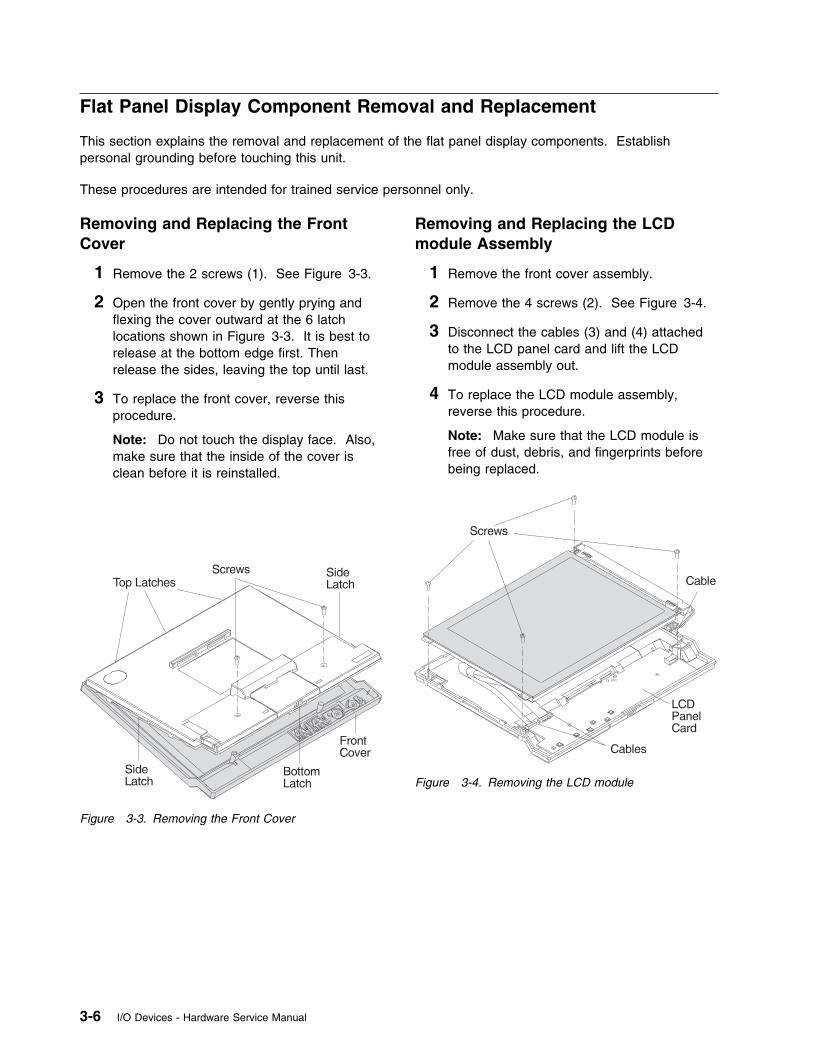
Removing and Replacing the FrontCover
1 Remove the 2 screws (1). See Figure 3-3.
2 Open the front cover by gently prying andflexing the cover outward at the 6 latchlocations shown in Figure 3-3. It is best torelease at the bottom edge first. Thenrelease the sides, leaving the top until last.
3 To replace the front cover, reverse thisprocedure.
Note: Do not touch the display face. Also,make sure that the inside of the cover isclean before it is reinstalled.
Figure 3-3. Removing the Front Cover
Removing and Replacing the LCDmodule Assembly
1 Remove the front cover assembly.
2 Remove the 4 screws (2). See Figure 3-4.
3 Disconnect the cables (3) and (4) attachedto the LCD panel card and lift the LCDmodule assembly out.
4 To replace the LCD module assembly,reverse this procedure.
Note: Make sure that the LCD module isfree of dust, debris, and fingerprints beforebeing replaced.
Figure 3-4. Removing the LCD module
3-6 I/O Devices - Hardware Service Manual
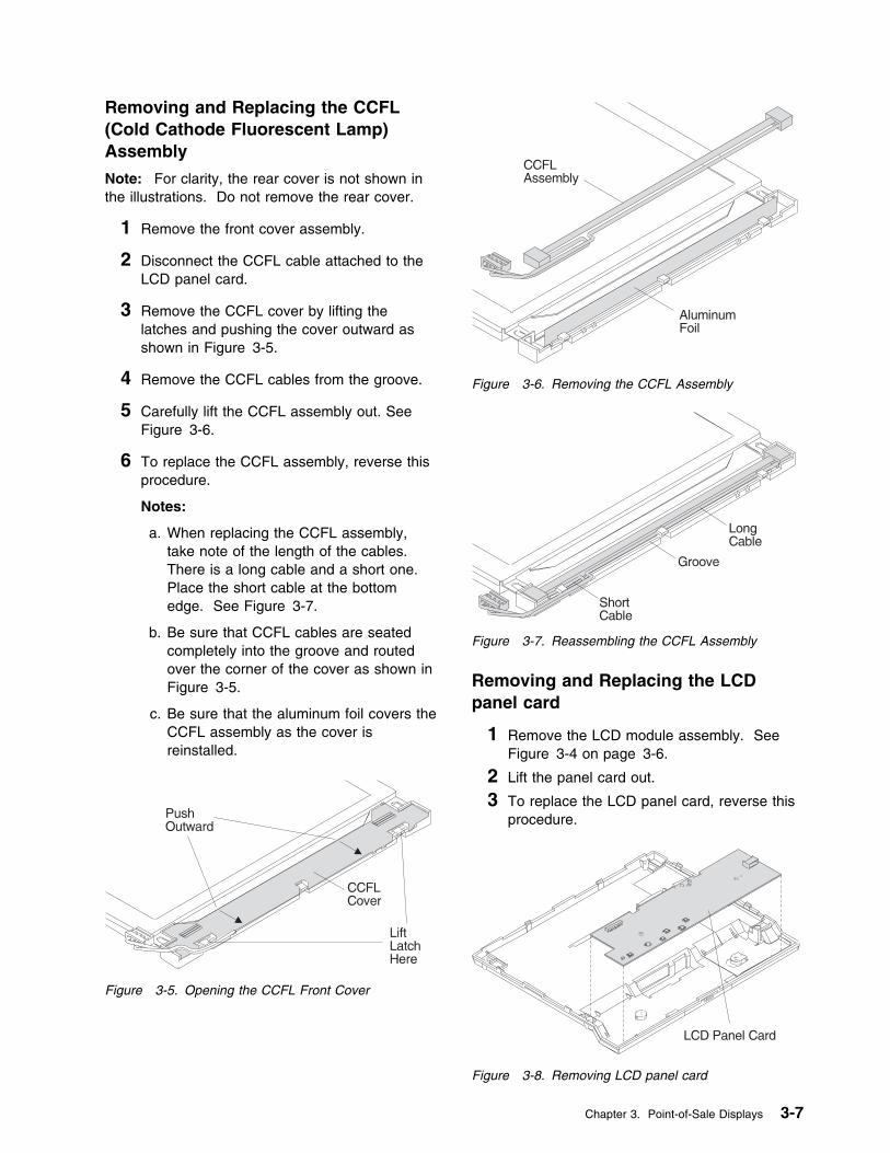
Removing and Replacing the CCFL(Cold Cathode Fluorescent Lamp)Assembly
Note: For clarity, the rear cover is not shown inthe illustrations. Do not remove the rear cover.
1 Remove the front cover assembly.
2 Disconnect the CCFL cable attached to theLCD panel card.
3 Remove the CCFL cover by lifting thelatches and pushing the cover outward asshown in Figure 3-5.
4 Remove the CCFL cables from the groove.
5 Carefully lift the CCFL assembly out. SeeFigure 3-6.
6 To replace the CCFL assembly, reverse thisprocedure.
Notes:
a. When replacing the CCFL assembly,take note of the length of the cables.There is a long cable and a short one.Place the short cable at the bottomedge. See Figure 3-7.
b. Be sure that CCFL cables are seatedcompletely into the groove and routedover the corner of the cover as shown inFigure 3-5.
c. Be sure that the aluminum foil covers theCCFL assembly as the cover isreinstalled.
Figure 3-5. Opening the CCFL Front Cover
Figure 3-6. Removing the CCFL Assembly
Figure 3-7. Reassembling the CCFL Assembly
Removing and Replacing the LCDpanel card
1 Remove the LCD module assembly. SeeFigure 3-4 on page 3-6.
2 Lift the panel card out.
3 To replace the LCD panel card, reverse thisprocedure.
Figure 3-8. Removing LCD panel card
Chapter 3. Point-of-Sale Displays 3-7
Removing and Replacing the FlatFiller Panel
See the Installation and Operation Guide forPoint-of-Sale Input/Output Devices.
Removing and Replacing theDisplay Cable
Removing and replacing the display cable is thesame as “Removing and Replacing the IntegrationKit” on page 3-20 or “Removing and Replacingthe Distribution Kit” on page 3-19. See theseprocedures.
Sure Point Touch Screens
The Sure Point Touch Display is a 9.5 inch liquid crystal display (LCD) with a backlight (cold cathodefluorescent lamp). The Sure Point Touch display attaches to all 4693 and 4694 Point-of-Sale Terminalsexcept the 4693 Model 2x2. To attach the display to the 4693 or 4694 Point-of-Sale Terminal an adapterand one of following kits are required:
� Integration kit � Distribution kit� Cash Drawer Integration kit
The integration kit allows the display to be integrated on an IBM 4693 Point-of-Sale Terminal system unit(except 4693 Model 2x2) and on an IBM 4694 Model 041, 044, and 144 system unit. It offers independenttilt, swivel, and rotate action for flexibility and easy positioning.
The distribution kit allows the display to be installed on a countertop. It offers independent tilt and swivelrotate action for flexibility and easy positioning.
The Cash Drawer Integration Kit allows the display to be integrated on IBM 4693 Cash Drawer. It offersindependent tilt, swivel, and rotate action for flexibility and easy positioning.
Touch Display Controls
Controls on the front of the touch display are used to change contrast, brightness, and reverse video.
Sleep/Resume The left-hand round button controls the sleep and resume functions.
Reverse Video The right-hand round button switches the display between normal and reverse video.This function is available on the monochrome model only.
Brightness The left-hand pair of up and down triangle buttons control the brightness. Thebrightness changes continuously with the allowable range while the buttons arepressed.
Contrast The right-hand pair of up and down triangle buttons control the contrast. The contrastchanges continuously within the allowable range while the buttons are pressed.
Touch Display Beeper Controls
The beeper controls on the front of the touch display change the frequency and loudness of the beeper.
Beeper Controls
Frequency The right-hand pair of up and down triangle buttons and the reverse video/shift buttonpressed at the same time control the frequency of the beeper. The frequency changescontinuously within the allowable range (1500-3500 Hz) while the buttons are pressed.
Loudness The left-hand pair of up and down triangle buttons and the reverse video/shift buttonpressed at the same time control the loudness of beeper.
3-8 I/O Devices - Hardware Service Manual
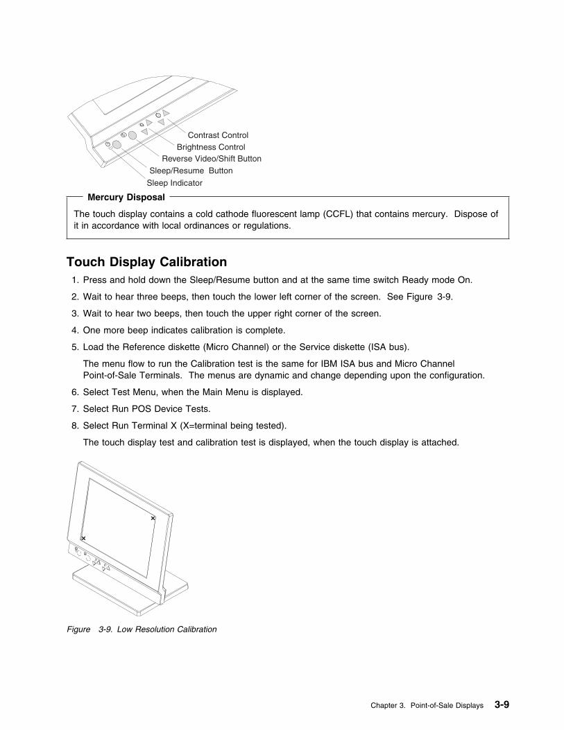
Contrast ControlBrightness Control
Reverse Video/Shift Button
Sleep/Resume Button
Sleep Indicator Mercury Disposal
The touch display contains a cold cathode fluorescent lamp (CCFL) that contains mercury. Dispose ofit in accordance with local ordinances or regulations.
Touch Display Calibration1. Press and hold down the Sleep/Resume button and at the same time switch Ready mode On.
2. Wait to hear three beeps, then touch the lower left corner of the screen. See Figure 3-9.
3. Wait to hear two beeps, then touch the upper right corner of the screen.
4. One more beep indicates calibration is complete.
5. Load the Reference diskette (Micro Channel) or the Service diskette (ISA bus).
The menu flow to run the Calibration test is the same for IBM ISA bus and Micro ChannelPoint-of-Sale Terminals. The menus are dynamic and change depending upon the configuration.
6. Select Test Menu, when the Main Menu is displayed.
7. Select Run POS Device Tests.
8. Select Run Terminal X (X=terminal being tested).
The touch display test and calibration test is displayed, when the touch display is attached.
Figure 3-9. Low Resolution Calibration
Chapter 3. Point-of-Sale Displays 3-9
Touch Display Sleep Control
There is an indicator and a button on the front of the display for sleep control. Table 3-3 on page 3-10describes how to control the sleep modes.
Table 3-3. Sleep Control
SleepIndicator
Is ON when the display is in sleep mode. This also indicates the mode while using setup.
Sleep/ResumeButton
The left round button controls the sleep/resume function of the display.
AutoSleepMode
In this mode, the display enters the sleep condition when the amount of time programmed bythe backlight command has passed after the last touch. The time can be programmed in therange of 1 to 65535 seconds, using the SIO command.
The display resumes when one or more of the following conditions are met:
1 The screen is touched.
2 Sleep/Resume button is pushed.
In this mode, the Sleep/Resume does not cause the display to go to sleep.
3 SIO Backlight command is issued.
ManualSleepMode
In this mode, the display switches between sleep and resume by pressing the Sleep/Resumebutton.The Sleep/Resume button or SIO commands can be used to put the display to sleep.
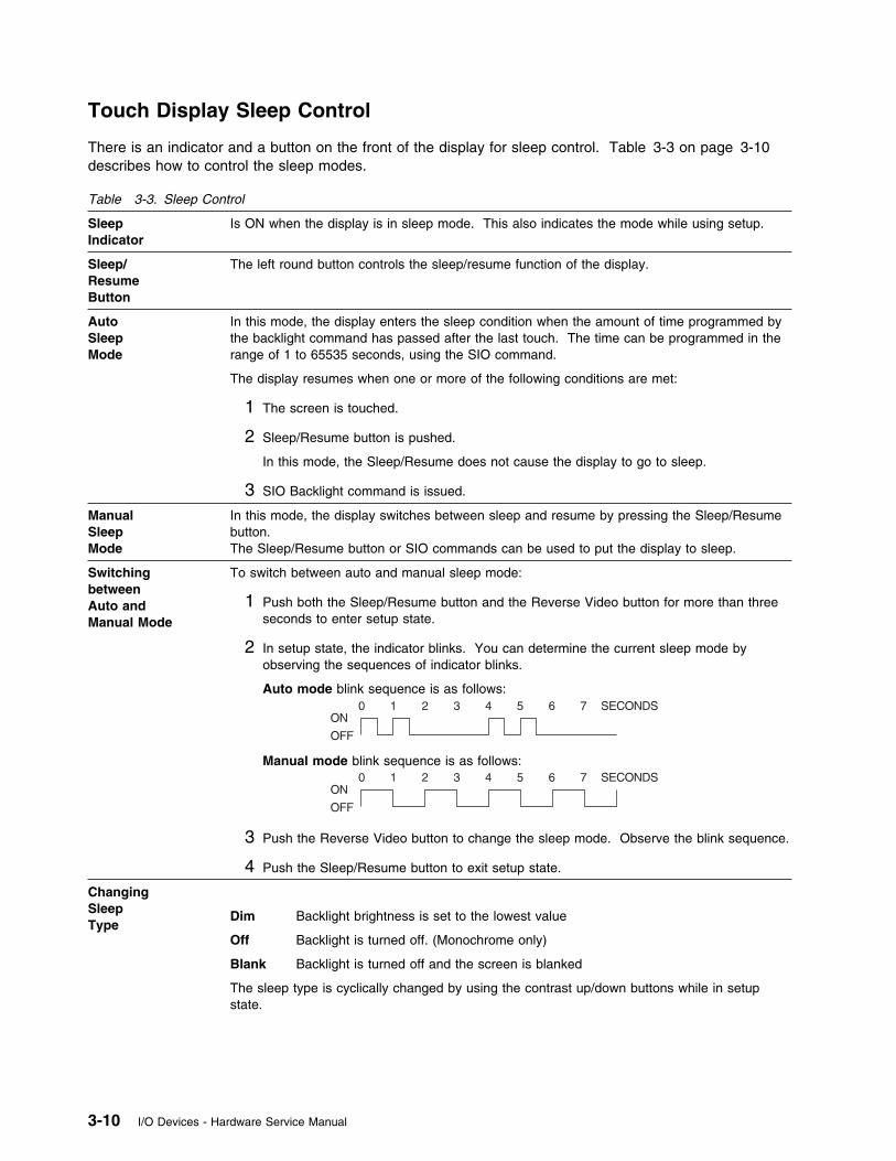
SwitchingbetweenAuto andManual Mode
To switch between auto and manual sleep mode:
1 Push both the Sleep/Resume button and the Reverse Video button for more than threeseconds to enter setup state.
2 In setup state, the indicator blinks. You can determine the current sleep mode byobserving the sequences of indicator blinks.
Auto mode blink sequence is as follows:
Manual mode blink sequence is as follows:
3 Push the Reverse Video button to change the sleep mode. Observe the blink sequence.
4 Push the Sleep/Resume button to exit setup state.
ChangingSleepType
Dim Backlight brightness is set to the lowest value
Off Backlight is turned off. (Monochrome only)
Blank Backlight is turned off and the screen is blanked
The sleep type is cyclically changed by using the contrast up/down buttons while in setupstate.
3-10 I/O Devices - Hardware Service Manual
Touch Display Symptoms
The actions listed below are for trained service personnel only.
The upper half and lower half of the LCD are controlled separately and a horizontal center line may beslightly visible.
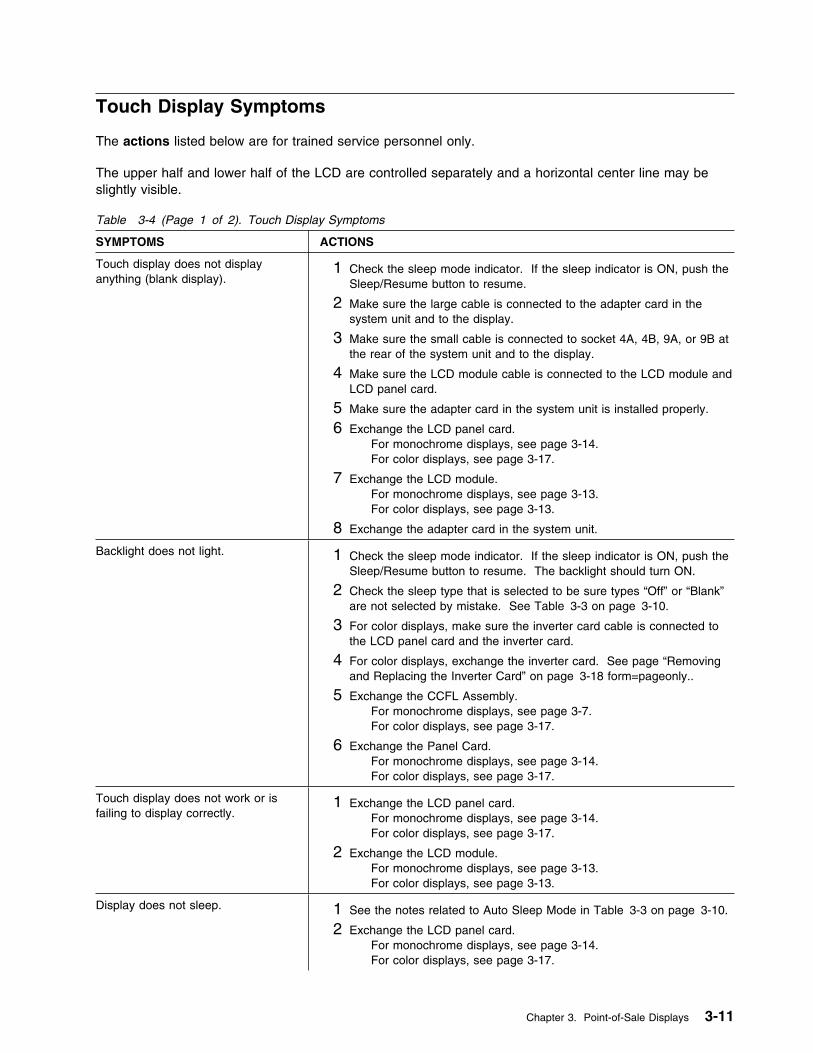
Table 3-4 (Page 1 of 2). Touch Display Symptoms
SYMPTOMS ACTIONS
Touch display does not displayanything (blank display).
1 Check the sleep mode indicator. If the sleep indicator is ON, push theSleep/Resume button to resume.
2 Make sure the large cable is connected to the adapter card in thesystem unit and to the display.
3 Make sure the small cable is connected to socket 4A, 4B, 9A, or 9B atthe rear of the system unit and to the display.
4 Make sure the LCD module cable is connected to the LCD module andLCD panel card.
5 Make sure the adapter card in the system unit is installed properly.
6 Exchange the LCD panel card.For monochrome displays, see page 3-14.For color displays, see page 3-17.
7 Exchange the LCD module.For monochrome displays, see page 3-13.For color displays, see page 3-13.
8 Exchange the adapter card in the system unit.
Backlight does not light. 1 Check the sleep mode indicator. If the sleep indicator is ON, push theSleep/Resume button to resume. The backlight should turn ON.
2 Check the sleep type that is selected to be sure types “Off” or “Blank”are not selected by mistake. See Table 3-3 on page 3-10.
3 For color displays, make sure the inverter card cable is connected tothe LCD panel card and the inverter card.
4 For color displays, exchange the inverter card. See page “Removingand Replacing the Inverter Card” on page 3-18 form=pageonly..
5 Exchange the CCFL Assembly.For monochrome displays, see page 3-7.For color displays, see page 3-17.
6 Exchange the Panel Card.For monochrome displays, see page 3-14.For color displays, see page 3-17.
Touch display does not work or isfailing to display correctly.
1 Exchange the LCD panel card.For monochrome displays, see page 3-14.For color displays, see page 3-17.
2 Exchange the LCD module.For monochrome displays, see page 3-13.For color displays, see page 3-13.
Display does not sleep. 1 See the notes related to Auto Sleep Mode in Table 3-3 on page 3-10.
2 Exchange the LCD panel card.For monochrome displays, see page 3-14.For color displays, see page 3-17.
Chapter 3. Point-of-Sale Displays 3-11

Table 3-4 (Page 2 of 2). Touch Display Symptoms
SYMPTOMS ACTIONS
Brightness or contrast controls do notcause a change.
1 Make sure that the brightness or contrast is not at its maximum (highor low).
2 Exchange the LCD panel card.For monochrome displays, see page 3-14.For color displays, see page 3-17.
Reverse Video button does not work. Exchange the LCD panel card.
For monochrome displays, see page 3-14.For color displays, see page 3-17.
1 long and x short BEEPs duringPOST (x = 2, 3, 5 or 6)
Exchange the adapter card in the system unit.
1 long and 4 short BEEPS duringPOST
1 Make sure the cables are connected properly.
2 Exchange the LCD panel card.For monochrome displays, see page 3-14.For color displays, see page 3-17.
3 Exchange the adapter card in the system unit.
Touch Display Testing
The touch display and adapter are tested each time that power is switched ON. If you get an errormessage or failure symptom, see “Touch Display Messages” or “Touch Display Symptoms” on page 3-11.
To perform a more complete test of the touch display, the following diskettes are required:
IBM 4693 Point-of-Sale Terminals: Reference Diskette, SX27-3918IBM 4695 Service Diskette Version 1.00 (or later), SX27-3965IBM Touch Display Adapter/A - Option Diskette Version 1.00 (or later), SX27-3966
Touch Display Messages
When the Mode Control Switch is pressed to switch Ready mode ON and storage retention is disabled,power-on self-test (POST) on the touch display adapter is performed automatically. This messageindicates an error detected by POST.
0148nnxn
Explanation: An IBM 4695 Point-of-Sale Adapter/A or IBM Touch Display Adapter/A error occurred.(n = any number)(x = slot number)
User Response: Exchange the adapter card.
3-12 I/O Devices - Hardware Service Manual
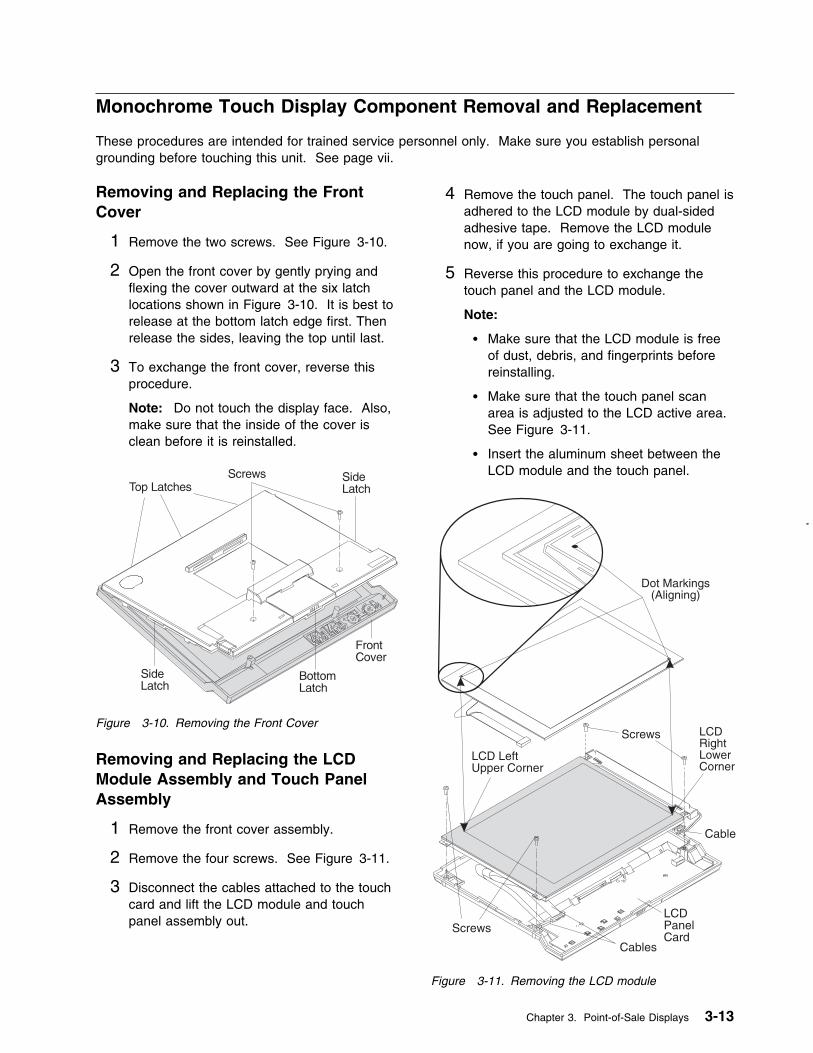
Monochrome Touch Display Component Removal and Replacement
These procedures are intended for trained service personnel only. Make sure you establish personalgrounding before touching this unit. See page vii.
Removing and Replacing the FrontCover
1 Remove the two screws. See Figure 3-10.
2 Open the front cover by gently prying andflexing the cover outward at the six latchlocations shown in Figure 3-10. It is best torelease at the bottom latch edge first. Thenrelease the sides, leaving the top until last.
3 To exchange the front cover, reverse thisprocedure.
Note: Do not touch the display face. Also,make sure that the inside of the cover isclean before it is reinstalled.
Figure 3-10. Removing the Front Cover
Removing and Replacing the LCDModule Assembly and Touch PanelAssembly
1 Remove the front cover assembly.
2 Remove the four screws. See Figure 3-11.
3 Disconnect the cables attached to the touchcard and lift the LCD module and touchpanel assembly out.
4 Remove the touch panel. The touch panel isadhered to the LCD module by dual-sidedadhesive tape. Remove the LCD modulenow, if you are going to exchange it.
5 Reverse this procedure to exchange thetouch panel and the LCD module.
Note:
� Make sure that the LCD module is freeof dust, debris, and fingerprints beforereinstalling.
� Make sure that the touch panel scanarea is adjusted to the LCD active area.See Figure 3-11.
� Insert the aluminum sheet between theLCD module and the touch panel.
Screws
LCD LeftUpper Corner
LCDRightLowerCorner
Dot Markings(Aligning)
Screws
Cable
Cables
LCDPanelCard
Figure 3-11. Removing the LCD module
Chapter 3. Point-of-Sale Displays 3-13
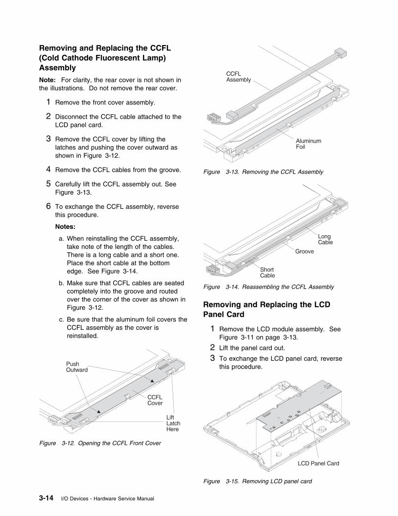
Removing and Replacing the CCFL(Cold Cathode Fluorescent Lamp)Assembly
Note: For clarity, the rear cover is not shown inthe illustrations. Do not remove the rear cover.
1 Remove the front cover assembly.
2 Disconnect the CCFL cable attached to theLCD panel card.
3 Remove the CCFL cover by lifting thelatches and pushing the cover outward asshown in Figure 3-12.
4 Remove the CCFL cables from the groove.
5 Carefully lift the CCFL assembly out. SeeFigure 3-13.
6 To exchange the CCFL assembly, reversethis procedure.
Notes:
a. When reinstalling the CCFL assembly,take note of the length of the cables.There is a long cable and a short one.Place the short cable at the bottomedge. See Figure 3-14.
b. Make sure that CCFL cables are seatedcompletely into the groove and routedover the corner of the cover as shown inFigure 3-12.
c. Be sure that the aluminum foil covers theCCFL assembly as the cover isreinstalled.
Figure 3-12. Opening the CCFL Front Cover
Figure 3-13. Removing the CCFL Assembly
Figure 3-14. Reassembling the CCFL Assembly
Removing and Replacing the LCDPanel Card
1 Remove the LCD module assembly. SeeFigure 3-11 on page 3-13.
2 Lift the panel card out.
3 To exchange the LCD panel card, reversethis procedure.
Figure 3-15. Removing LCD panel card
3-14 I/O Devices - Hardware Service Manual

Color Touch Display Component Removal and Replacement
These procedures are intended for trained service personnel only. Make sure you establish personalgrounding before touching this unit.
Removing and Replacing theFront Cover
1 Remove the two screws. See Figure 3-16.
2 Open the front cover by gently prying andflexing the cover outward at the six latchlocations shown in Figure 3-16. It is best torelease at the bottom latch edge first. Thenrelease the sides, leaving the top until last.
3 To exchange the front cover, reverse thisprocedure.
Note: Do not touch the display face. Also,make sure that the inside of the cover isclean before it is reinstalled. Figure 3-16. Removing the Front Cover
Chapter 3. Point-of-Sale Displays 3-15
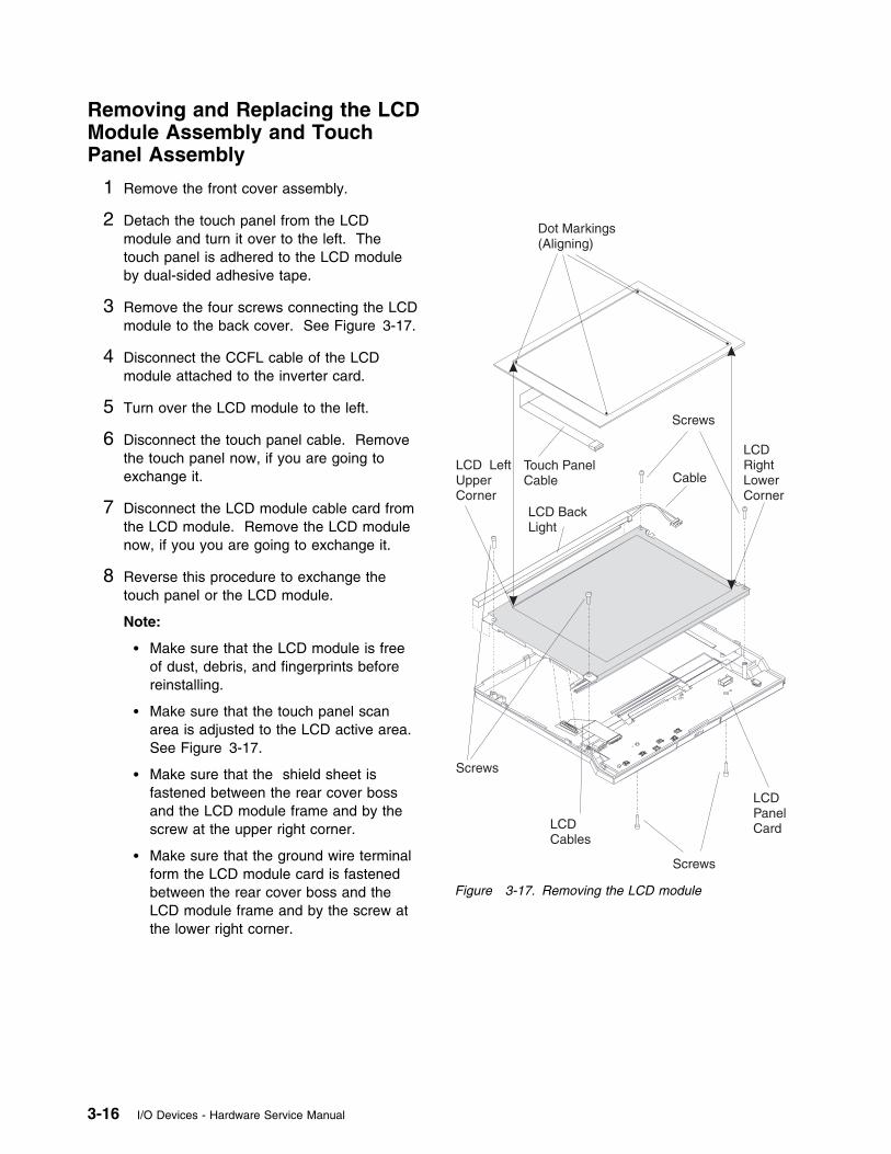
Removing and Replacing the LCDModule Assembly and TouchPanel Assembly
1 Remove the front cover assembly.
2 Detach the touch panel from the LCDmodule and turn it over to the left. Thetouch panel is adhered to the LCD moduleby dual-sided adhesive tape.
3 Remove the four screws connecting the LCDmodule to the back cover. See Figure 3-17.
4 Disconnect the CCFL cable of the LCDmodule attached to the inverter card.
5 Turn over the LCD module to the left.
6 Disconnect the touch panel cable. Removethe touch panel now, if you are going toexchange it.
7 Disconnect the LCD module cable card fromthe LCD module. Remove the LCD modulenow, if you you are going to exchange it.
8 Reverse this procedure to exchange thetouch panel or the LCD module.
Note:
� Make sure that the LCD module is freeof dust, debris, and fingerprints beforereinstalling.
� Make sure that the touch panel scanarea is adjusted to the LCD active area.See Figure 3-17.
� Make sure that the shield sheet isfastened between the rear cover bossand the LCD module frame and by thescrew at the upper right corner.
� Make sure that the ground wire terminalform the LCD module card is fastenedbetween the rear cover boss and theLCD module frame and by the screw atthe lower right corner.
Screws
LCDCables
LCDPanelCard
Cable
LCDRightLowerCorner
LCD LeftUpperCorner
LCD BackLight
Screws
Screws
Touch PanelCable
Dot Markings(Aligning)
Figure 3-17. Removing the LCD module
3-16 I/O Devices - Hardware Service Manual
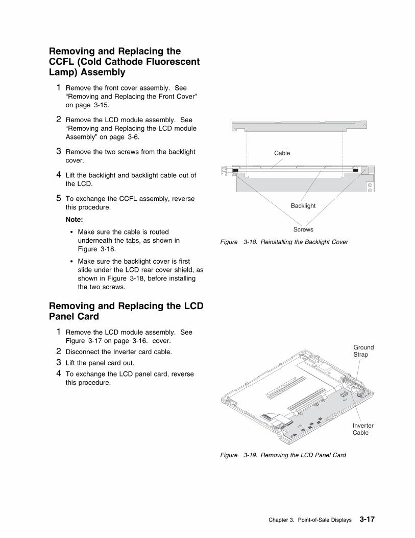
Removing and Replacing theCCFL (Cold Cathode FluorescentLamp) Assembly
1 Remove the front cover assembly. See“Removing and Replacing the Front Cover”on page 3-15.
2 Remove the LCD module assembly. See“Removing and Replacing the LCD moduleAssembly” on page 3-6.
3 Remove the two screws from the backlightcover.
4 Lift the backlight and backlight cable out ofthe LCD.
5 To exchange the CCFL assembly, reversethis procedure.
Note:
� Make sure the cable is routedunderneath the tabs, as shown inFigure 3-18.
� Make sure the backlight cover is firstslide under the LCD rear cover shield, asshown in Figure 3-18, before installingthe two screws.
Removing and Replacing the LCDPanel Card
1 Remove the LCD module assembly. SeeFigure 3-17 on page 3-16. cover.
2 Disconnect the Inverter card cable.
3 Lift the panel card out.
4 To exchange the LCD panel card, reversethis procedure.
Cable
Backlight
Screws
Figure 3-18. Reinstalling the Backlight Cover
InverterCable
GroundStrap
Figure 3-19. Removing the LCD Panel Card
Chapter 3. Point-of-Sale Displays 3-17
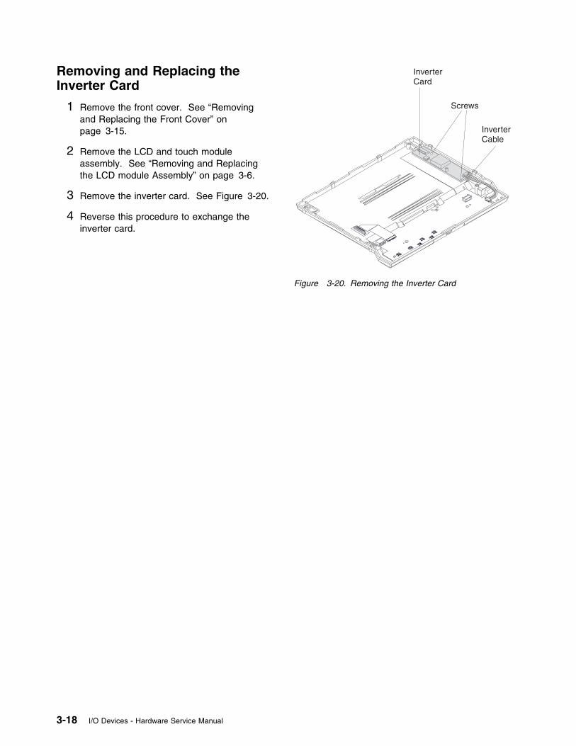
Removing and Replacing theInverter Card
1 Remove the front cover. See “Removingand Replacing the Front Cover” onpage 3-15.
2 Remove the LCD and touch moduleassembly. See “Removing and Replacingthe LCD module Assembly” on page 3-6.
3 Remove the inverter card. See Figure 3-20.
4 Reverse this procedure to exchange theinverter card.
Screws
InverterCard
InverterCable
Figure 3-20. Removing the Inverter Card
3-18 I/O Devices - Hardware Service Manual
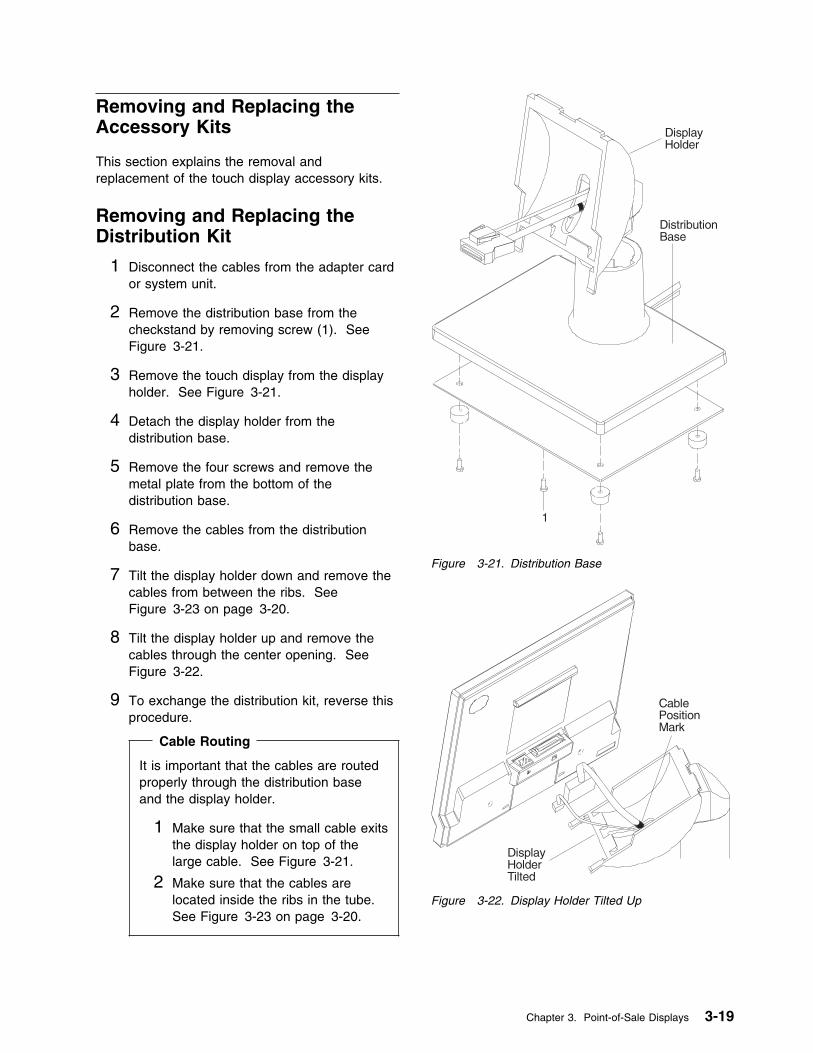
Removing and Replacing theAccessory Kits
This section explains the removal andreplacement of the touch display accessory kits.
Removing and Replacing theDistribution Kit
1 Disconnect the cables from the adapter cardor system unit.
2 Remove the distribution base from thecheckstand by removing screw (1). SeeFigure 3-21.
3 Remove the touch display from the displayholder. See Figure 3-21.
4 Detach the display holder from thedistribution base.
5 Remove the four screws and remove themetal plate from the bottom of thedistribution base.
6 Remove the cables from the distributionbase.
7 Tilt the display holder down and remove thecables from between the ribs. SeeFigure 3-23 on page 3-20.
8 Tilt the display holder up and remove thecables through the center opening. SeeFigure 3-22.
9 To exchange the distribution kit, reverse thisprocedure. Cable Routing
It is important that the cables are routedproperly through the distribution baseand the display holder.
1 Make sure that the small cable exitsthe display holder on top of thelarge cable. See Figure 3-21.
2 Make sure that the cables arelocated inside the ribs in the tube.See Figure 3-23 on page 3-20.
Figure 3-21. Distribution Base
Figure 3-22. Display Holder Tilted Up
Chapter 3. Point-of-Sale Displays 3-19
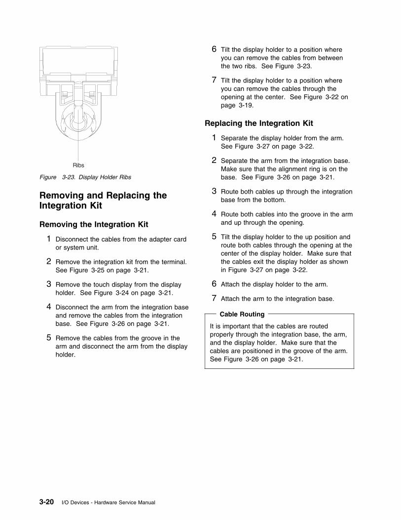
Figure 3-23. Display Holder Ribs
Removing and Replacing theIntegration Kit
Removing the Integration Kit
1 Disconnect the cables from the adapter cardor system unit.
2 Remove the integration kit from the terminal.See Figure 3-25 on page 3-21.
3 Remove the touch display from the displayholder. See Figure 3-24 on page 3-21.
4 Disconnect the arm from the integration baseand remove the cables from the integrationbase. See Figure 3-26 on page 3-21.
5 Remove the cables from the groove in thearm and disconnect the arm from the displayholder.
6 Tilt the display holder to a position whereyou can remove the cables from betweenthe two ribs. See Figure 3-23.
7 Tilt the display holder to a position whereyou can remove the cables through theopening at the center. See Figure 3-22 onpage 3-19.
Replacing the Integration Kit
1 Separate the display holder from the arm.See Figure 3-27 on page 3-22.
2 Separate the arm from the integration base.Make sure that the alignment ring is on thebase. See Figure 3-26 on page 3-21.
3 Route both cables up through the integrationbase from the bottom.
4 Route both cables into the groove in the armand up through the opening.
5 Tilt the display holder to the up position androute both cables through the opening at thecenter of the display holder. Make sure thatthe cables exit the display holder as shownin Figure 3-27 on page 3-22.
6 Attach the display holder to the arm.
7 Attach the arm to the integration base.
Cable Routing
It is important that the cables are routedproperly through the integration base, the arm,and the display holder. Make sure that thecables are positioned in the groove of the arm.See Figure 3-26 on page 3-21.
3-20 I/O Devices - Hardware Service Manual
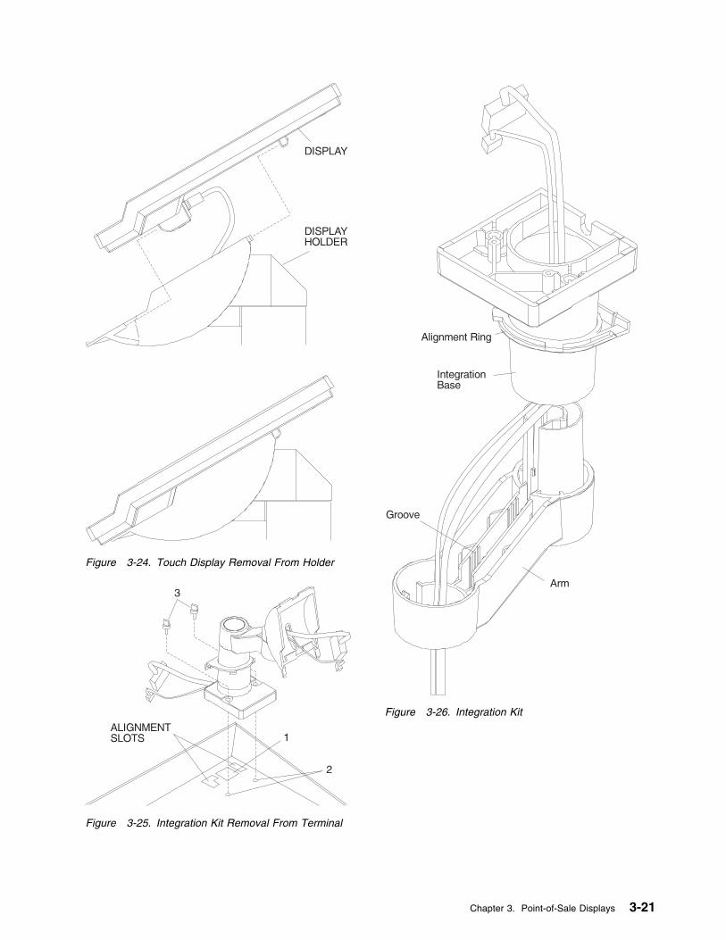
Figure 3-24. Touch Display Removal From Holder
Figure 3-25. Integration Kit Removal From Terminal
Figure 3-26. Integration Kit
Chapter 3. Point-of-Sale Displays 3-21
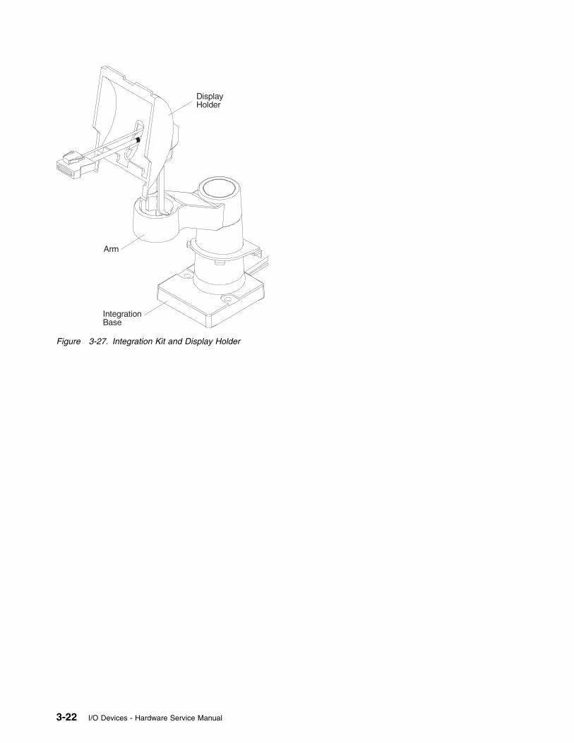
Figure 3-27. Integration Kit and Display Holder
3-22 I/O Devices - Hardware Service Manual
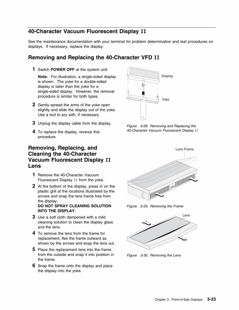
40-Character Vacuum Fluorescent Display II
See the maintenance documentation with your terminal for problem determination and test procedures ondisplays. If necessary, replace the display.
Removing and Replacing the 40-Character VFD II
1 Switch POWER OFF at the system unit.
Note: For illustration, a single-sided displayis shown. The yoke for a double-sideddisplay is taller than the yoke for asingle-sided display. However, the removalprocedure is similar for both types.
2 Gently spread the arms of the yoke openslightly and slide the display out of the yoke.Use a tool to pry with, if necessary.
3 Unplug the display cable from the display.
4 To replace the display, reverse thisprocedure.
Removing, Replacing, andCleaning the 40-CharacterVacuum Fluorescent Display IILens
1 Remove the 40-Character VacuumFluorescent Display II from the yoke.
2 At the bottom of the display, press in on theplastic grill at the locations illustrated by thearrows and snap the lens frame free fromthe display.DO NOT SPRAY CLEANING SOLUTIONINTO THE DISPLAY.
3 Use a soft cloth dampened with a mildcleaning solution to clean the display glassand the lens.
4 To remove the lens from the frame forreplacement, flex the frame outward asshown by the arrows and snap the lens out.
5 Place the replacement lens into the framefrom the outside and snap it into position inthe frame.
6 Snap the frame onto the display and placethe display into the yoke.
Figure 3-28. Removing and Replacing the40-Character Vacuum Fluorescent Display II
Figure 3-29. Removing the Frame
Figure 3-30. Removing the Lens
Chapter 3. Point-of-Sale Displays 3-23
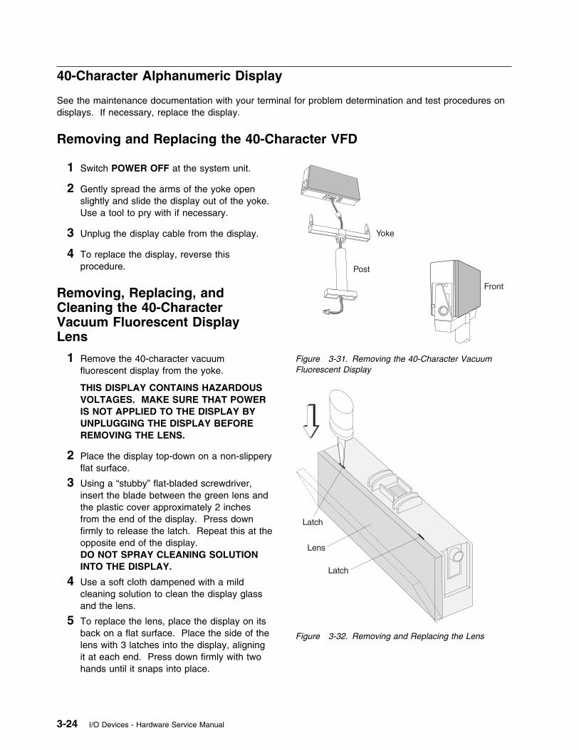
40-Character Alphanumeric Display
See the maintenance documentation with your terminal for problem determination and test procedures ondisplays. If necessary, replace the display.
Removing and Replacing the 40-Character VFD
1 Switch POWER OFF at the system unit.
2 Gently spread the arms of the yoke openslightly and slide the display out of the yoke.Use a tool to pry with if necessary.
3 Unplug the display cable from the display.
4 To replace the display, reverse thisprocedure.
Removing, Replacing, andCleaning the 40-CharacterVacuum Fluorescent DisplayLens
1 Remove the 40-character vacuumfluorescent display from the yoke.
THIS DISPLAY CONTAINS HAZARDOUSVOLTAGES. MAKE SURE THAT POWERIS NOT APPLIED TO THE DISPLAY BYUNPLUGGING THE DISPLAY BEFOREREMOVING THE LENS.
2 Place the display top-down on a non-slipperyflat surface.
3 Using a “stubby” flat-bladed screwdriver,insert the blade between the green lens andthe plastic cover approximately 2 inchesfrom the end of the display. Press downfirmly to release the latch. Repeat this at theopposite end of the display.DO NOT SPRAY CLEANING SOLUTIONINTO THE DISPLAY.
4 Use a soft cloth dampened with a mildcleaning solution to clean the display glassand the lens.
5 To replace the lens, place the display on itsback on a flat surface. Place the side of thelens with 3 latches into the display, aligningit at each end. Press down firmly with twohands until it snaps into place.
Front
Yoke
Post
Figure 3-31. Removing the 40-Character VacuumFluorescent Display
Figure 3-32. Removing and Replacing the Lens
3-24 I/O Devices - Hardware Service Manual
Chapter 4. Point-of-Sale Keyboards
This chapter contains repair information for POS keyboards. Exchange the enhanced alphanumeric(PS/2* type) and the matrix keyboards and cables when they fail. Other keyboards should be repaired.
DANGER
Never work on equipment or connect or disconnect signal cables during periods oflightning activity.
CAUTION:For your safety, connect equipment requiring electrical power to a properly wired and groundedoutlet.
Electrostatic Discharge (ESD)
Attention ESD damage can occur when there is a difference in charge between the part, the product, andthe service person. No damage will occur if the service person and the part being installed are at thesame charge level.
ESD Damage Prevention
Anytime a service action involves physical contact with logic cards, modules, back-panel pins, or otherESD sensitive (ESDS) parts, the service person must be connected to an ESD common ground point onthe product through the ESD wrist strap and cord.
The ESD ground clip can be attached to any frame ground, ground braid, green wire ground, or the roundground prong on the AC power plug. Coax or connector outside shells can also be used.
Handling Removed Cards
Logic cards removed from a product should be placed in ESD protective containers. No other objectshould be allowed inside the ESD container with the logic card. Attach tags or reports that mustaccompany the card to the outside of the container.
Keyboard and Card Reader Messages . . . . . . . . . . . . . . . . . . . . . . . . . . . . . . . . . . . . 4-3Keyboard and Card Reader Symptoms . . . . . . . . . . . . . . . . . . . . . . . . . . . . . . . . . . . . 4-5
Removing and Replacing the 50-Key Keyboard Components . . . . . . . . . . . . . . . . . . . . . . 4-7Removing and Replacing the Keyboard Cover . . . . . . . . . . . . . . . . . . . . . . . . . . . . . 4-7Removing and Replacing the Keypad Assembly . . . . . . . . . . . . . . . . . . . . . . . . . . . . 4-7Removing and Replacing the Logic Board . . . . . . . . . . . . . . . . . . . . . . . . . . . . . . . 4-7Removing the Manager’s Keylock . . . . . . . . . . . . . . . . . . . . . . . . . . . . . . . . . . . . 4-7
Removing and Replacing Alphanumeric Keyboard Components . . . . . . . . . . . . . . . . . . . . 4-9Removing and Replacing the Keyboard Cover . . . . . . . . . . . . . . . . . . . . . . . . . . . . . 4-9Removing and Replacing the Indicator Light Assembly . . . . . . . . . . . . . . . . . . . . . . . . 4-9Removing and Replacing the Keypad Assembly . . . . . . . . . . . . . . . . . . . . . . . . . . . . 4-9Removing and Replacing the Manager’s Keylock . . . . . . . . . . . . . . . . . . . . . . . . . . . 4-9Removing and Replacing the Logic Board . . . . . . . . . . . . . . . . . . . . . . . . . . . . . . . 4-9Removing and Replacing the Speaker . . . . . . . . . . . . . . . . . . . . . . . . . . . . . . . . . 4-9
Removing and Replacing ANPOS Keyboard Components . . . . . . . . . . . . . . . . . . . . . . 4-11Removing and Replacing the Keyboard Cover . . . . . . . . . . . . . . . . . . . . . . . . . . . . 4-11
Copyright IBM Corp. 1993, 1995 4-1

Removing and Replacing the Keypad Assembly . . . . . . . . . . . . . . . . . . . . . . . . . . . 4-11Removing and Replacing the Logic Board . . . . . . . . . . . . . . . . . . . . . . . . . . . . . . 4-11Removing and Replacing the Manager’s Keylock . . . . . . . . . . . . . . . . . . . . . . . . . . 4-11Removing and Replacing the Manager’s Keylock Switch . . . . . . . . . . . . . . . . . . . . . . 4-11Removing and Replacing the Speaker . . . . . . . . . . . . . . . . . . . . . . . . . . . . . . . . 4-11Removing and Replacing the ANPOS Card Reader or Filler Cover . . . . . . . . . . . . . . . . 4-12
Removing and Replacing the RPOS Keyboard Family Components . . . . . . . . . . . . . . . . . 4-14Removing and Replacing the Keyboard Cover and Keypad Assembly . . . . . . . . . . . . . . 4-14Removing and Replacing the Logic Board . . . . . . . . . . . . . . . . . . . . . . . . . . . . . . 4-14Removing and Replacing the Manager’s Keylock Actuator Arm . . . . . . . . . . . . . . . . . . 4-15Removing and Replacing the Card Reader . . . . . . . . . . . . . . . . . . . . . . . . . . . . . . 4-15Removing and Replacing the Indicator Light Assembly . . . . . . . . . . . . . . . . . . . . . . . 4-15Removing and Replacing the Display Assembly . . . . . . . . . . . . . . . . . . . . . . . . . . . 4-16Removing and Replacing the Keyboard Legs . . . . . . . . . . . . . . . . . . . . . . . . . . . . 4-16
Removing and Replacing Combined Keyboard/Display Components . . . . . . . . . . . . . . . . 4-18Removing and Replacing the Keyboard Cover . . . . . . . . . . . . . . . . . . . . . . . . . . . . 4-18Removing and Replacing the Display Assembly . . . . . . . . . . . . . . . . . . . . . . . . . . . 4-18Removing and Replacing the Keypad Assembly . . . . . . . . . . . . . . . . . . . . . . . . . . . 4-18Removing and Replacing the Logic Board . . . . . . . . . . . . . . . . . . . . . . . . . . . . . . 4-18Removing and Replacing the Manager’s Keylock . . . . . . . . . . . . . . . . . . . . . . . . . . 4-18Removing and Replacing the Manager’s Keylock Switch . . . . . . . . . . . . . . . . . . . . . . 4-18Removing and Replacing the Speaker . . . . . . . . . . . . . . . . . . . . . . . . . . . . . . . . 4-19Removing and Replacing the Combined Keyboard/Display Card Reader . . . . . . . . . . . . 4-19
4-2 I/O Devices - Hardware Service Manual
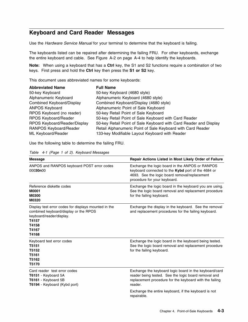
Keyboard and Card Reader Messages
Use the Hardware Service Manual for your terminal to determine that the keyboard is failing.
The keyboards listed can be repaired after determining the failing FRU. For other keyboards, exchangethe entire keyboard and cable. See Figure A-2 on page A-4 to help identify the keyboards.
Note: When using a keyboard that has a Ctrl key, the S1 and S2 functions require a combination of twokeys. First press and hold the Ctrl key then press the S1 or S2 key.
This document uses abbreviated names for some keyboards:
Abbreviated Name Full Name50-key Keyboard 50-key Keyboard (4680 style)Alphanumeric Keyboard Alphanumeric Keyboard (4680 style)Combined Keyboard/Display Combined Keyboard/Display (4680 style)ANPOS Keyboard Alphanumeric Point of Sale KeyboardRPOS Keyboard (no reader) 50-key Retail Point of Sale KeyboardRPOS Keyboard/Reader 50-key Retail Point of Sale Keyboard with Card ReaderRPOS Keyboard/Reader/Display 50-key Retail Point of Sale Keyboard with Card Reader and DisplayRANPOS Keyboard/Reader Retail Alphanumeric Point of Sale Keyboard with Card ReaderML Keyboard/Reader 133-key Modifiable Layout Keyboard with Reader
Use the following table to determine the failing FRU.
Table 4-1 (Page 1 of 2). Keyboard Messages
Message Repair Actions Listed in Most Likely Order of Failure
ANPOS and RANPOS keyboard POST error codes00030n00
Exchange the logic board in the ANPOS or RANPOSkeyboard connected to the Kybd port of the 4684 or4693. See the logic board removal/replacementprocedure for your keyboard.
Reference diskette codesM0001M0300M0320
Exchange the logic board in the keyboard you are using.See the logic board removal and replacement procedurefor the failing keyboard.
Display test error codes for displays mounted in thecombined keyboard/display or the RPOSkeyboard/reader/display.T4157T4158T4167T4168
Exchange the display in the keyboard. See the removaland replacement procedures for the failing keyboard.
Keyboard test error codesT5151T5152T5161T5162T5170
Exchange the logic board in the keyboard being tested.See the logic board removal and replacement procedurefor the failing keyboard.
Card reader test error codesT6151 - Keyboard 5AT6161 - Keyboard 5BT6194 - Keyboard (Kybd port)
Exchange the keyboard logic board in the keyboard/cardreader being tested. See the logic board removal andreplacement procedure for the keyboard with the failingreader.
Exchange the entire keyboard, if the keyboard is notrepairable.
Chapter 4. Point-of-Sale Keyboards 4-3
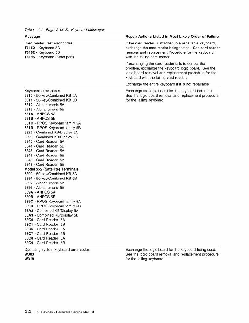
Table 4-1 (Page 2 of 2). Keyboard Messages
Message Repair Actions Listed in Most Likely Order of Failure
Card reader test error codesT6152 - Keyboard 5AT6162 - Keyboard 5BT6195 - Keyboard (Kybd port)
If the card reader is attached to a repairable keyboard,exchange the card reader being tested. See card readerremoval and replacement Procedure for the keyboardwith the failing card reader.
If exchanging the card reader fails to correct theproblem, exchange the keyboard logic board. See thelogic board removal and replacement procedure for thekeyboard with the failing card reader.
Exchange the entire keyboard if it is not repairable.
Keyboard error codes6310 - 50-key/Combined KB 5A6311 - 50-key/Combined KB 5B6312 - Alphanumeric 5A6313 - Alphanumeric 5B631A - ANPOS 5A631B - ANPOS 5B631C - RPOS Keyboard family 5A631D - RPOS Keyboard family 5B6322 - Combined KB/Display 5A6323 - Combined KB/Display 5B6340 - Card Reader 5A6341 - Card Reader 5B6346 - Card Reader 5A6347 - Card Reader 5B6348 - Card Reader 5A6349 - Card Reader 5BModel xx2 (Satellite) Terminals6390 - 50-key/Combined KB 5A6391 - 50-key/Combined KB 5B6392 - Alphanumeric 5A6393 - Alphanumeric 5B639A - ANPOS 5A639B - ANPOS 5B639C - RPOS Keyboard family 5A639D - RPOS Keyboard family 5B63A2 - Combined KB/Display 5A63A3 - Combined KB/Display 5B63C0 - Card Reader 5A63C1 - Card Reader 5B63C6 - Card Reader 5A63C7 - Card Reader 5B63C8 - Card Reader 5A63C9 - Card Reader 5B
Exchange the logic board for the keyboard indicated.See the logic board removal and replacement procedurefor the failing keyboard.
Operating system keyboard error codesW303W318
Exchange the logic board for the keyboard being used.See the logic board removal and replacement procedurefor the failing keyboard.
4-4 I/O Devices - Hardware Service Manual
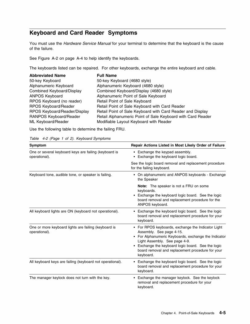
Keyboard and Card Reader Symptoms
You must use the Hardware Service Manual for your terminal to determine that the keyboard is the causeof the failure.
See Figure A-2 on page A-4 to help identify the keyboards.
The keyboards listed can be repaired. For other keyboards, exchange the entire keyboard and cable.
Abbreviated Name Full Name50-key Keyboard 50-key Keyboard (4680 style)Alphanumeric Keyboard Alphanumeric Keyboard (4680 style)Combined Keyboard/Display Combined Keyboard/Display (4680 style)ANPOS Keyboard Alphanumeric Point of Sale KeyboardRPOS Keyboard (no reader) Retail Point of Sale KeyboardRPOS Keyboard/Reader Retail Point of Sale Keyboard with Card ReaderRPOS Keyboard/Reader/Display Retail Point of Sale Keyboard with Card Reader and DisplayRANPOS Keyboard/Reader Retail Alphanumeric Point of Sale Keyboard with Card ReaderML Keyboard/Reader Modifiable Layout Keyboard with Reader
Use the following table to determine the failing FRU.
Table 4-2 (Page 1 of 2). Keyboard Symptoms
Symptom Repair Actions Listed in Most Likely Order of Failure
One or several keyboard keys are failing (keyboard isoperational).
� Exchange the keypad assembly.� Exchange the keyboard logic board.
See the logic board removal and replacement procedurefor the failing keyboard.
Keyboard tone, audible tone, or speaker is failing. � On alphanumeric and ANPOS keyboards - Exchangethe Speaker
Note: The speaker is not a FRU on somekeyboards.
� Exchange the keyboard logic board. See the logicboard removal and replacement procedure for theANPOS keyboard.
All keyboard lights are ON (keyboard not operational). � Exchange the keyboard logic board. See the logicboard removal and replacement procedure for yourkeyboard.
One or more keyboard lights are failing (keyboard isoperational).
� For RPOS keyboards, exchange the Indicator LightAssembly. See page 4-15.
� For Alphanumeric Keyboards, exchange the IndicatorLight Assembly. See page 4-9.
� Exchange the keyboard logic board. See the logicboard removal and replacement procedure for yourkeyboard.
All keyboard keys are failing (keyboard not operational). � Exchange the keyboard logic board. See the logicboard removal and replacement procedure for yourkeyboard.
The manager keylock does not turn with the key. � Exchange the manager keylock. See the keylockremoval and replacement procedure for yourkeyboard.
Chapter 4. Point-of-Sale Keyboards 4-5
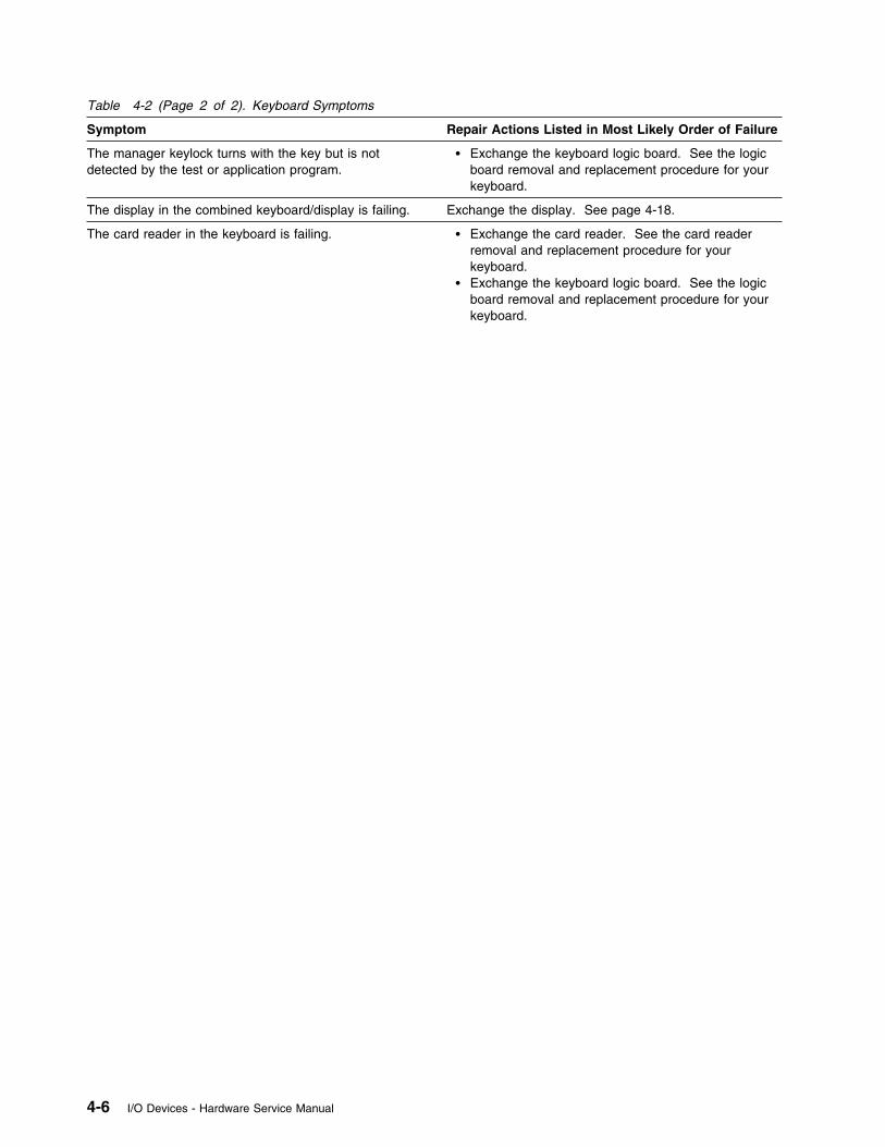
Table 4-2 (Page 2 of 2). Keyboard Symptoms
Symptom Repair Actions Listed in Most Likely Order of Failure
The manager keylock turns with the key but is notdetected by the test or application program.
� Exchange the keyboard logic board. See the logicboard removal and replacement procedure for yourkeyboard.
The display in the combined keyboard/display is failing. Exchange the display. See page 4-18.
The card reader in the keyboard is failing. � Exchange the card reader. See the card readerremoval and replacement procedure for yourkeyboard.
� Exchange the keyboard logic board. See the logicboard removal and replacement procedure for yourkeyboard.
4-6 I/O Devices - Hardware Service Manual

Removing and Replacing the 50-Key Keyboard Components
See Figure 4-1 on page 4-8 when removing and replacing 50-key keyboard components.
Removing and Replacing the KeyboardCover
1 Set the manager keylock to the OFF(clockwise) position.
2 Press in on the back-center of the keyboard(1).
3 Lift up on the back of the keyboard cover(2), move it toward the front of the keyboardbase, and lift it off.
To exchange the keyboard cover, reversethis procedure.
Removing and Replacing the KeypadAssembly
1 Remove the keyboard cover.
2 Remove the grounding screw (5).
3 Lift the keypad (6) off the mounting posts(10).
4 Disconnect the cables and lift the keypad outof the keyboard base.
To exchange the keypad assembly, reversethis procedure.
Removing and Replacing the LogicBoard
1 Remove the keyboard cover.
2 Remove the keypad assembly.
3 Remove the screws (11).
4 Release the latches (7) at the front edge ofthe logic board (8).
5 Move the logic board from under the tabs (9)at the back of the keyboard base and lift itout of the base.
To exchange the logic board, reverse thisprocedure.
Removing the Manager’s Keylock
1 Remove the keyboard cover.
2 Remove the keylock retainer (4).
3 Lift the keylock (3) out of the keyboardcover.
To exchange the keylock, reverse thisprocedure.
Chapter 4. Point-of-Sale Keyboards 4-7
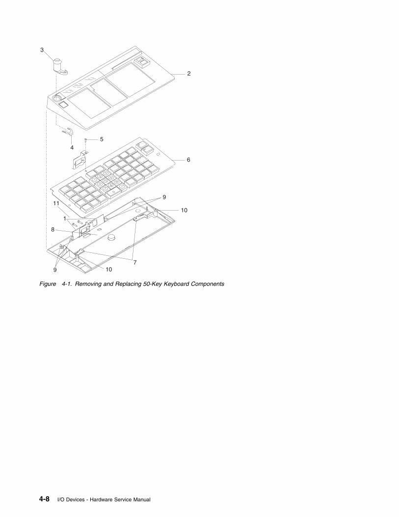
1
2
3
45
6
7
8
9
9 10
1011
Figure 4-1. Removing and Replacing 50-Key Keyboard Components
4-8 I/O Devices - Hardware Service Manual
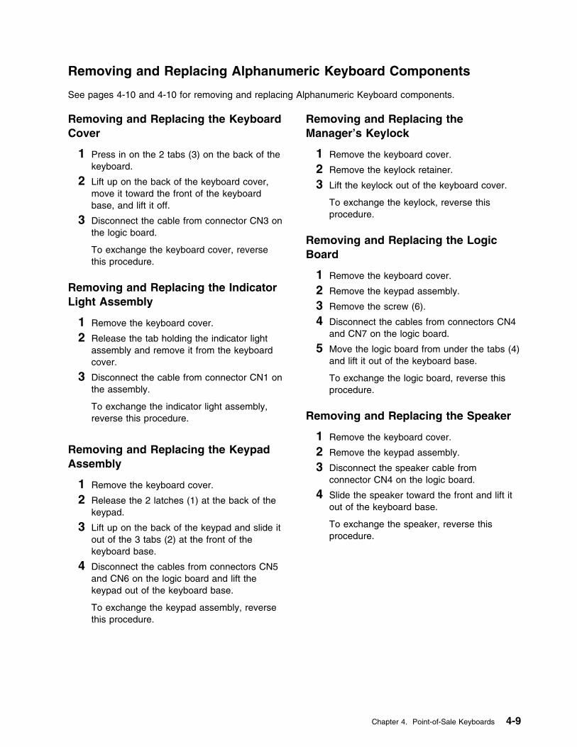
Removing and Replacing Alphanumeric Keyboard Components
See pages 4-10 and 4-10 for removing and replacing Alphanumeric Keyboard components.
Removing and Replacing the KeyboardCover
1 Press in on the 2 tabs (3) on the back of thekeyboard.
2 Lift up on the back of the keyboard cover,move it toward the front of the keyboardbase, and lift it off.
3 Disconnect the cable from connector CN3 onthe logic board.
To exchange the keyboard cover, reversethis procedure.
Removing and Replacing the IndicatorLight Assembly
1 Remove the keyboard cover.
2 Release the tab holding the indicator lightassembly and remove it from the keyboardcover.
3 Disconnect the cable from connector CN1 onthe assembly.
To exchange the indicator light assembly,reverse this procedure.
Removing and Replacing the KeypadAssembly
1 Remove the keyboard cover.
2 Release the 2 latches (1) at the back of thekeypad.
3 Lift up on the back of the keypad and slide itout of the 3 tabs (2) at the front of thekeyboard base.
4 Disconnect the cables from connectors CN5and CN6 on the logic board and lift thekeypad out of the keyboard base.
To exchange the keypad assembly, reversethis procedure.
Removing and Replacing theManager’s Keylock
1 Remove the keyboard cover.
2 Remove the keylock retainer.
3 Lift the keylock out of the keyboard cover.
To exchange the keylock, reverse thisprocedure.
Removing and Replacing the LogicBoard
1 Remove the keyboard cover.
2 Remove the keypad assembly.
3 Remove the screw (6).
4 Disconnect the cables from connectors CN4and CN7 on the logic board.
5 Move the logic board from under the tabs (4)and lift it out of the keyboard base.
To exchange the logic board, reverse thisprocedure.
Removing and Replacing the Speaker
1 Remove the keyboard cover.
2 Remove the keypad assembly.
3 Disconnect the speaker cable fromconnector CN4 on the logic board.
4 Slide the speaker toward the front and lift itout of the keyboard base.
To exchange the speaker, reverse thisprocedure.
Chapter 4. Point-of-Sale Keyboards 4-9
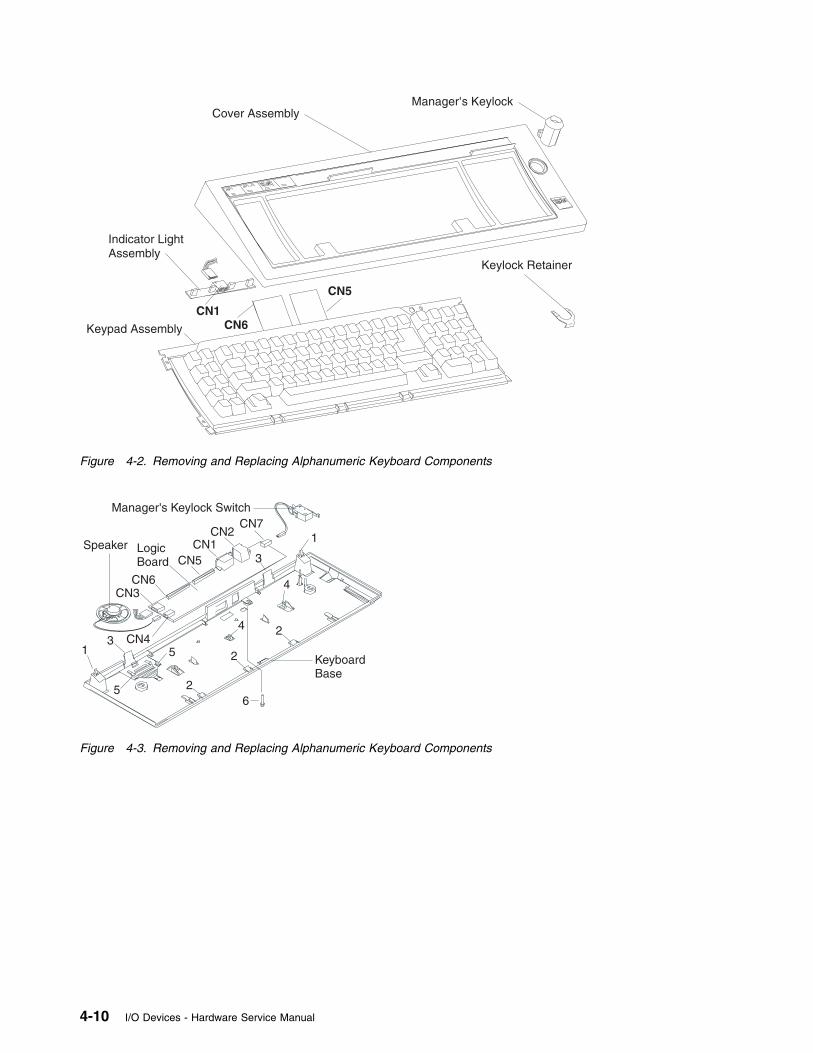
Cover AssemblyManager's Keylock
Keylock Retainer
CN5
CN6CN1
Keypad Assembly
Indicator LightAssembly
Figure 4-2. Removing and Replacing Alphanumeric Keyboard Components
Speaker
KeyboardBase
1
1
3
35
5
LogicBoard
CN4
CN3
CN2
4
4
CN7
CN6
CN5CN1
6
2
2
2
Manager's Keylock Switch
Figure 4-3. Removing and Replacing Alphanumeric Keyboard Components
4-10 I/O Devices - Hardware Service Manual
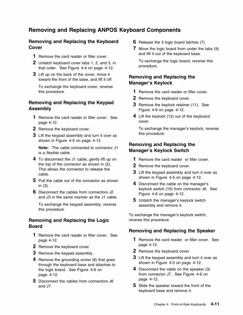
Removing and Replacing ANPOS Keyboard Components
Removing and Replacing the KeyboardCover
1 Remove the card reader or filler cover.
2 Unlatch keyboard cover tabs 1, 2, and 3, inthat order. See Figure 4-4 on page 4-12.
3 Lift up on the back of the cover, move ittoward the front of the base, and lift it off.
To exchange the keyboard cover, reversethis procedure.
Removing and Replacing the KeypadAssembly
1 Remove the card reader or filler cover. Seepage 4-12.
2 Remove the keyboard cover.
3 Lift the keypad assembly and turn it over asshown in Figure 4-5 on page 4-12.
Note: The cable connected to connector J1is a flexible cable.
4 To disconnect the J1 cable, gently lift up onthe top of the connector as shown in (2).This allows the connector to release thecable.
5 Pull the cable out of the connector as shownin (3).
6 Disconnect the cables from connectors J2and J3 in the same manner as the J1 cable.
To exchange the keypad assembly, reversethis procedure.
Removing and Replacing the LogicBoard
1 Remove the card reader or filler cover. Seepage 4-12.
2 Remove the keyboard cover.
3 Remove the keypad assembly.
4 Remove the grounding screw (8) that goesthrough the keyboard base and attaches tothe logic board. See Figure 4-6 onpage 4-12.
5 Disconnect the cables from connectors J6and J7.
6 Release the 3 logic board latches (7).
7 Move the logic board from under the tabs (9)and lift it out of the keyboard base.
To exchange the logic board, reverse thisprocedure.
Removing and Replacing theManager’s Keylock
1 Remove the card reader or filler cover.
2 Remove the keyboard cover.
3 Remove the keylock retainer (11). SeeFigure 4-6 on page 4-12.
4 Lift the keylock (12) out of the keyboardcover.
To exchange the manager’s keylock, reversethis procedure.
Removing and Replacing theManager’s Keylock Switch
1 Remove the card reader or filler cover.
2 Remove the keyboard cover.
3 Lift the keypad assembly and turn it over asshown in Figure 4-5 on page 4-12.
4 Disconnect the cable on the manager’skeylock switch (10) from connector J6. SeeFigure 4-6 on page 4-12.
5 Unlatch the manager’s keylock switchassembly and remove it.
To exchange the manager’s keylock switch,reverse this procedure.
Removing and Replacing the Speaker
1 Remove the card reader or filler cover. Seepage 4-12.
2 Remove the keyboard cover.
3 Lift the keypad assembly and turn it over asshown in Figure 4-5 on page 4-12.
4 Disconnect the cable on the speaker (3)from connector J7. See Figure 4-6 onpage 4-12.
5 Slide the speaker toward the front of thekeyboard base and remove it.
Chapter 4. Point-of-Sale Keyboards 4-11
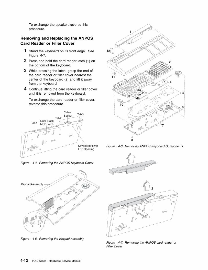
To exchange the speaker, reverse thisprocedure.
Removing and Replacing the ANPOSCard Reader or Filler Cover
1 Stand the keyboard on its front edge. SeeFigure 4-7.
2 Press and hold the card reader latch (1) onthe bottom of the keyboard.
3 While pressing the latch, grasp the end ofthe card reader or filler cover nearest thecenter of the keyboard (2) and lift it awayfrom the keyboard.
4 Continue lifting the card reader or filler coveruntil it is removed from the keyboard.
To exchange the card reader or filler cover,reverse this procedure.
Figure 4-4. Removing the ANPOS Keyboard Cover
J1J2
J3
1 2 3
Keypad Assembly
Figure 4-5. Removing the Keypad Assembly
1
2
3
4
5
6
7
8
9
10
11
12
J1 J2J3
J4
J5
J6
J7
Figure 4-6. Removing ANPOS Keyboard Components
1
2
Figure 4-7. Removing the ANPOS card reader orFiller Cover
4-12 I/O Devices - Hardware Service Manual
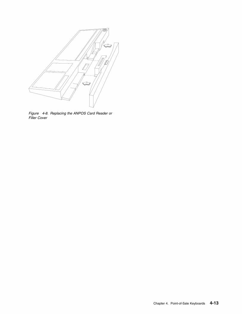
Figure 4-8. Replacing the ANPOS Card Reader orFiller Cover
Chapter 4. Point-of-Sale Keyboards 4-13
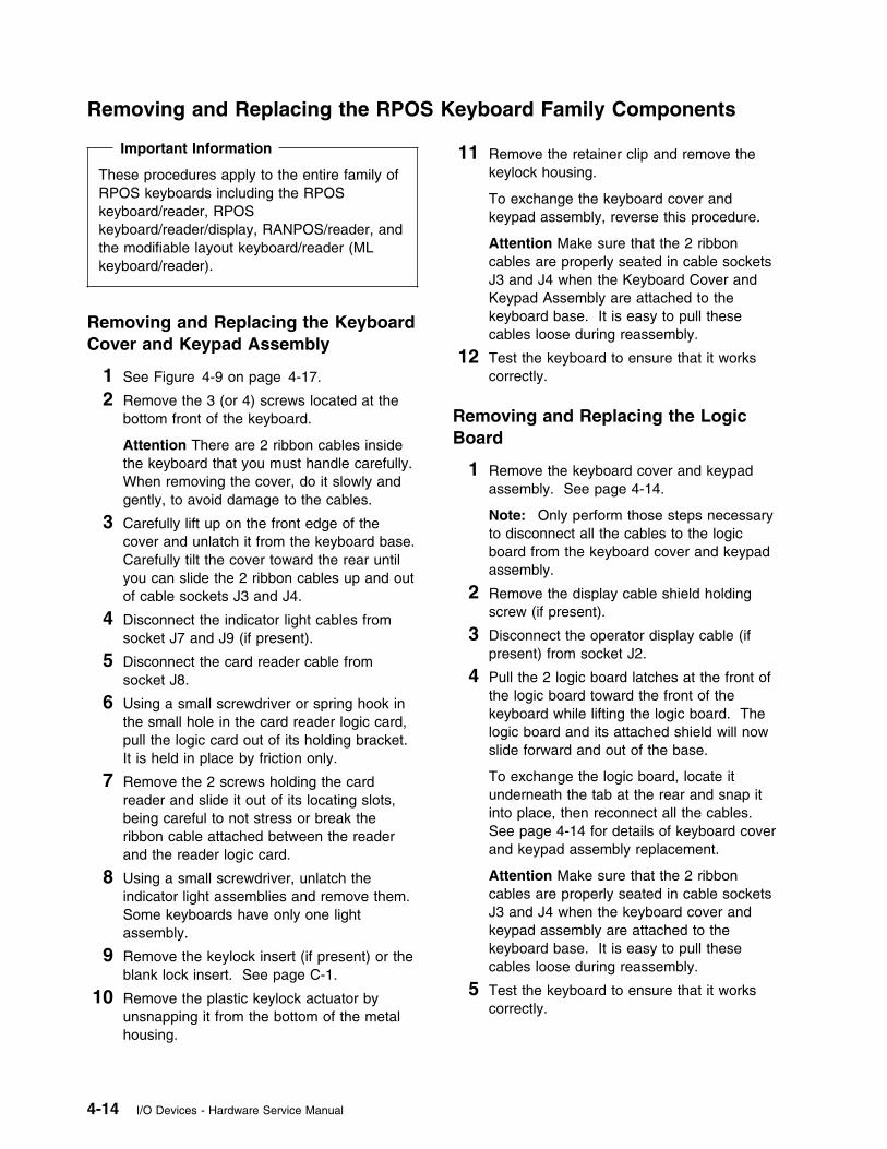
Removing and Replacing the RPOS Keyboard Family Components
Important Information
These procedures apply to the entire family ofRPOS keyboards including the RPOSkeyboard/reader, RPOSkeyboard/reader/display, RANPOS/reader, andthe modifiable layout keyboard/reader (MLkeyboard/reader).
Removing and Replacing the KeyboardCover and Keypad Assembly
1 See Figure 4-9 on page 4-17.
2 Remove the 3 (or 4) screws located at thebottom front of the keyboard.
Attention There are 2 ribbon cables insidethe keyboard that you must handle carefully.When removing the cover, do it slowly andgently, to avoid damage to the cables.
3 Carefully lift up on the front edge of thecover and unlatch it from the keyboard base.Carefully tilt the cover toward the rear untilyou can slide the 2 ribbon cables up and outof cable sockets J3 and J4.
4 Disconnect the indicator light cables fromsocket J7 and J9 (if present).
5 Disconnect the card reader cable fromsocket J8.
6 Using a small screwdriver or spring hook inthe small hole in the card reader logic card,pull the logic card out of its holding bracket.It is held in place by friction only.
7 Remove the 2 screws holding the cardreader and slide it out of its locating slots,being careful to not stress or break theribbon cable attached between the readerand the reader logic card.
8 Using a small screwdriver, unlatch theindicator light assemblies and remove them.Some keyboards have only one lightassembly.
9 Remove the keylock insert (if present) or theblank lock insert. See page C-1.
10 Remove the plastic keylock actuator byunsnapping it from the bottom of the metalhousing.
11 Remove the retainer clip and remove thekeylock housing.
To exchange the keyboard cover andkeypad assembly, reverse this procedure.
Attention Make sure that the 2 ribboncables are properly seated in cable socketsJ3 and J4 when the Keyboard Cover andKeypad Assembly are attached to thekeyboard base. It is easy to pull thesecables loose during reassembly.
12 Test the keyboard to ensure that it workscorrectly.
Removing and Replacing the LogicBoard
1 Remove the keyboard cover and keypadassembly. See page 4-14.
Note: Only perform those steps necessaryto disconnect all the cables to the logicboard from the keyboard cover and keypadassembly.
2 Remove the display cable shield holdingscrew (if present).
3 Disconnect the operator display cable (ifpresent) from socket J2.
4 Pull the 2 logic board latches at the front ofthe logic board toward the front of thekeyboard while lifting the logic board. Thelogic board and its attached shield will nowslide forward and out of the base.
To exchange the logic board, locate itunderneath the tab at the rear and snap itinto place, then reconnect all the cables.See page 4-14 for details of keyboard coverand keypad assembly replacement.
Attention Make sure that the 2 ribboncables are properly seated in cable socketsJ3 and J4 when the keyboard cover andkeypad assembly are attached to thekeyboard base. It is easy to pull thesecables loose during reassembly.
5 Test the keyboard to ensure that it workscorrectly.
4-14 I/O Devices - Hardware Service Manual
Removing and Replacing theManager’s Keylock Actuator Arm
1 Remove the keyboard cover and keypadassembly. See page 4-14.
Note: Only perform those steps necessaryto allow you to gain access to the keylockassembly.
2 Remove the broken or defective actuatorarm from the keylock assembly. Ifnecessary, pry it free with a screwdriver.
3 Press the replacement actuator arm into thekeylock assembly until it latches into place.
4 Reinstall the cover and keypad assemblymaking sure to connect all cables that weredisconnected.
Attention Make sure that the 2 ribboncables are properly seated in cable socketsJ3 and J4 when the keyboard cover andkeypad assembly are attached to thekeyboard base. It is easy to pull thesecables loose during reassembly.
5 Test the keyboard to ensure that it workscorrectly.
Removing and Replacing the CardReader
1 Remove the 3 (or 4) screws located at thebottom front of the keyboard.
Attention There are 2 ribbon cables insidethe keyboard that you must handle carefully.When removing the cover, do it slowly andgently, to avoid damage to the ribbon cables.
2 Carefully lift up on the front edge of thecover and unlatch it from the keyboard base.Carefully tilt the cover toward the rear untilyou can slide the 2 ribbon cables up and outof cable sockets J3 and J4.
3 Disconnect the card reader cable thatconnects to cable socket J8.
4 Using a small screwdriver or spring hook inthe small hole in the card reader logic card,pull the logic card out of its holding bracket.It is held in place by friction only.
5 Remove the 2 screws holding the cardreader and slide it out of its locating slots
being careful to not stress or break theribbon cable attached between the readerand the reader logic card.
6 To exchange the card reader assembly,reverse this procedure.
Attention Make sure that the 2 ribboncables are properly seated in their sockets(J3 and J4) when the keyboard cover andkeypad assembly is attached to thekeyboard base. It is easy to pull thesecables loose during reassembly.
7 Test the keyboard to ensure that it workscorrectly.
Removing and Replacing the IndicatorLight Assembly
1 Remove the 3 (or 4) screws located at thebottom front of the keyboard.
Attention There are 2 ribbon cables insidethe keyboard that you must handle carefully.When removing the cover, do it slowly andgently, to avoid damage to the ribbon cables.
2 Carefully lift up on the front edge of thecover and unlatch it from the keyboard base.Carefully tilt the cover toward the rear untilyou can slide the 2 ribbon cables up and outof cable sockets J3 and J4.
3 Disconnect the card reader cable at socketJ8.
4 Disconnect the cables from the indicator lightassemblies that connect to socket J7 and J9.Some keyboards have only one indicatorassembly.
5 There are 2 latches on each assembly thatyou can get to without removing the cardreader . Using a small screwdriver, unlatchthe indicator light assembly and remove it.
6 To exchange the indicator light assembly,reverse this procedure.
Attention Make sure that the 2 ribboncables are properly seated in cable socketsJ3 and J4 when the keyboard cover andkeypad assembly are attached to thekeyboard base. It is easy to pull thesecables loose during reassembly.
7 Test the keyboard to ensure that it workscorrectly.
Chapter 4. Point-of-Sale Keyboards 4-15
Removing and Replacing the DisplayAssembly
1 Remove the 3 (or 4) screws located at thebottom front of the keyboard.
Attention There are 2 ribbon cables insidethe keyboard that you must handle carefully.When removing the cover, do it slowly andgently, to avoid damage to the ribbon cables.
2 Carefully lift up on the front edge of thecover and it unlatch it from the keyboardbase. Carefully tilt the cover toward the rearuntil you can slide the 2 ribbon cables upand out of cable sockets J3 and J4.
3 Disconnect the cables from sockets J7, J8,and J9.
4 Remove the display cable shield holdingscrew from the logic board.
5 Disconnect the operator display cable fromsocket J2.
6 Remove the logic board.
7 Lift the display out of the keyboard.
8 To exchange the display assembly, reversethis procedure.
Attention Make sure that the 2 ribboncables are properly seated in cable socketsJ3 and J4 when the keyboard cover andkeypad assembly is attached to thekeyboard base. It is easy to pull thesecables loose during reassembly.
9 Test the keyboard to ensure that it workscorrectly.
Removing and Replacing the KeyboardLegs
1 Rotate the legs so that they hold thekeyboard in the tilted position.
2 Each leg has a small slot visible from theside. Using a small screwdriver, pry the legoff its mounting post.
3 To exchange the leg, position the leg so thatthe keyboard tilts and push it to snap it intoplace on the mounting post.
4-16 I/O Devices - Hardware Service Manual
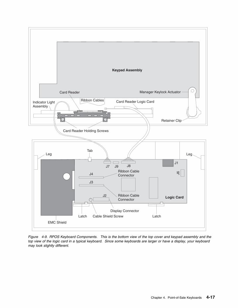
Keypad Assembly
Manager Keylock Actuator
Retainer Clip
Leg
J1J8J9J7
J4
J3
J2 Ribbon CableConnector
Ribbon CableConnector
Logic Card
Latch
Display Connector
Cable Shield ScrewLatch
EMC Shield
LegTab
J6
Card Reader Logic CardRibbon Cables
Card Reader
Indicator LightAssembly
Card Reader Holding Screws
Figure 4-9. RPOS Keyboard Components. This is the bottom view of the top cover and keypad assembly and thetop view of the logic card in a typical keyboard. Since some keyboards are larger or have a display, your keyboardmay look slightly different.
Chapter 4. Point-of-Sale Keyboards 4-17
Removing and Replacing Combined Keyboard/Display Components
Removing and Replacing the KeyboardCover
1 Remove the card reader or filler cover. Seepage 4-19.
2 Unlatch keyboard cover tabs 1, 2, and 3, inthat order. See Figure 4-10 on page 4-19.
3 Lift up on the back of the cover, move ittoward the front of the keyboard, and lift itoff.
To exchange the keyboard cover, reversethis procedure.
Removing and Replacing the DisplayAssembly
1 Remove the card reader or filler cover. Seepage 4-19.
2 Remove the keyboard cover.
3 Disconnect the cable from the display. SeeFigure 4-11 on page 4-19.
4 Lift the display from the display posts.
To exchange the display, reverse thisprocedure.
Removing and Replacing the KeypadAssembly
1 Remove the card reader or filler cover. Seepage 4-19.
2 Remove the keyboard cover.
3 Remove the grounding screw (18). SeeFigure 4-13 on page 4-20.
4 Lift the keypad assembly and turn it over asshown in Figure 4-12 on page 4-19.
5 Disconnect the cables from cable sockets J4and J7. See Figure 4-13 on page 4-20.
To exchange the keypad assembly, reversethis procedure.
Removing and Replacing the LogicBoard
1 Remove the card reader or filler cover. Seepage 4-19.
2 Remove the keyboard cover. See page4-18.
3 Remove the keypad assembly. See page4-18.
4 Remove the display assembly. See page4-18.
5 Remove the grounding screw (17) that goesthrough the keyboard base and attaches tothe logic board. See Figure 4-13 onpage 4-20.
6 Disconnect the cables from cable sockets J1and J5.
7 Release the 3 logic board latches (15).
8 Move the logic board from under the tabs(10) and lift it out of the keyboard base.
To exchange the logic board, reverse thisprocedure.
Removing and Replacing theManager’s Keylock
1 Remove the card reader or filler cover. Seepage 4-19.
2 Remove the keyboard cover. See page4-18.
3 Remove the keylock retainer (3). SeeFigure 4-13 on page 4-20.
4 Lift the keylock (1) out of the keyboardcover.
To exchange the manager’s keylock, reversethis procedure.
Removing and Replacing theManager’s Keylock Switch
1 Remove the card reader or filler cover. Seepage 4-19.
2 Remove the keyboard cover. See page4-18.
3 Lift the keypad assembly and turn it over asshown in Figure 4-13 on page 4-20.
4-18 I/O Devices - Hardware Service Manual

4 Disconnect the cable on the manager’skeylock switch (9) from cable socket J1.See Figure 4-13 on page 4-20.
5 Unlatch the manager’s keylock switchassembly and remove it.
To exchange the manager’s keylock switch,reverse this procedure.
Removing and Replacing the Speaker
1 Remove the card reader or filler cover. Seepage 4-19.
2 Remove the keyboard cover. See page4-18.
3 Remove the display assembly. See page4-18.
4 Remove the keypad assembly. See page4-18.
5 Remove the logic board.
6 Disconnect the cable on the speaker (7)from cable socket J5. See Figure 4-13 onpage 4-20.
7 Slide the speaker toward the back of thekeyboard base and remove it.
To exchange the speaker, reverse thisprocedure.
Removing and Replacing theCombined Keyboard/Display CardReader
1 Stand the keyboard on its front edge. SeeFigure 4-14 on page 4-20.
2 Press and hold the MSR latch (1) on thebottom of the keyboard.
3 While pressing the latch, grasp the end ofthe card reader or filler cover nearest thecenter of the keyboard (2) and lift it awayfrom the keyboard.
4 Continue lifting the card reader or fillercover until it is removed from the keyboard.
To exchange the card reader or filler cover,reverse this procedure.
Figure 4-10. Removing the Keyboard Cover
Figure 4-11. Removing the Display
Figure 4-12. Removing the Keypad
Chapter 4. Point-of-Sale Keyboards 4-19
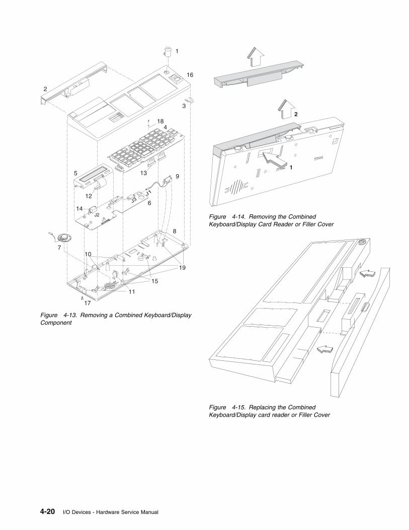
J2
J1
J3
3
1
2
4
5
6
7
8
9
10
11
12
13
14
15
16
17
18
19
Figure 4-13. Removing a Combined Keyboard/DisplayComponent
1
2
Figure 4-14. Removing the CombinedKeyboard/Display Card Reader or Filler Cover
Figure 4-15. Replacing the CombinedKeyboard/Display card reader or Filler Cover
4-20 I/O Devices - Hardware Service Manual
Chapter 5. Point-of-Sale Printer Model 1 or Model 2
DANGER
Never work on equipment or connect or disconnect signal cables during periods oflightning activity.
CAUTION:For your safety, connect equipment requiring electrical power to a properly wired and groundedoutlet.
Electrostatic Discharge (ESD)
Attention ESD damage can occur when there is a difference in charge between the part, the product, andthe service person. No damage will occur if the service person and the part being installed are at thesame charge level.
ESD Damage Prevention
Anytime a service action involves physical contact with logic cards, modules, back-panel pins, or otherESD sensitive (ESDS) parts, the service person must be connected to an ESD common ground point onthe product through the ESD wrist strap and cord.
The ESD ground clip can be attached to any frame ground, ground braid, green wire ground, or the roundground prong on the AC power plug. Coax or connector outside shells can also be used.
Handling Removed Cards
Logic cards removed from a product should be placed in ESD protective containers. No other objectshould be allowed inside the ESD container with the logic card. Attach tags or reports that mustaccompany the card to the outside of the container.
Note: Any time you are working on the printer it is a good idea to clean the sensors. This reduces thenumber of service calls due to dust and paper debris.
Printer Stand-Alone Test Procedure . . . . . . . . . . . . . . . . . . . . . . . . . . . . . . . . . . . . . . 5-4Printer Messages . . . . . . . . . . . . . . . . . . . . . . . . . . . . . . . . . . . . . . . . . . . . . . . . . 5-6Printer Symptoms . . . . . . . . . . . . . . . . . . . . . . . . . . . . . . . . . . . . . . . . . . . . . . . . 5-8Printer Repair Procedures (Models 1 and 2) . . . . . . . . . . . . . . . . . . . . . . . . . . . . . . . . 5-12
Adjusting the Print Head Cam . . . . . . . . . . . . . . . . . . . . . . . . . . . . . . . . . . . . . . . 5-12Adjusting the Print Head Home Sensor . . . . . . . . . . . . . . . . . . . . . . . . . . . . . . . . . 5-13Cleaning the Print Head . . . . . . . . . . . . . . . . . . . . . . . . . . . . . . . . . . . . . . . . . . 5-14Removing and Replacing the Access Cover . . . . . . . . . . . . . . . . . . . . . . . . . . . . . . . 5-16
Removing the Access Cover . . . . . . . . . . . . . . . . . . . . . . . . . . . . . . . . . . . . . . 5-16Replacing the Access Cover . . . . . . . . . . . . . . . . . . . . . . . . . . . . . . . . . . . . . . 5-16
Removing and Replacing the Bottom Cover . . . . . . . . . . . . . . . . . . . . . . . . . . . . . . . 5-17Removing the Bottom Cover . . . . . . . . . . . . . . . . . . . . . . . . . . . . . . . . . . . . . . 5-17Replacing the Bottom Cover . . . . . . . . . . . . . . . . . . . . . . . . . . . . . . . . . . . . . . 5-17
Removing and Replacing the Cover Interlock Sensor . . . . . . . . . . . . . . . . . . . . . . . . . 5-18Removing the Cover Interlock Sensor . . . . . . . . . . . . . . . . . . . . . . . . . . . . . . . . . 5-18Replacing the Cover Interlock Sensor . . . . . . . . . . . . . . . . . . . . . . . . . . . . . . . . . 5-18
Copyright IBM Corp. 1993, 1995 5-1

Removing and Replacing the Document Insert Paper Guide . . . . . . . . . . . . . . . . . . . . . 5-19Removing the Document Insert Paper Guide . . . . . . . . . . . . . . . . . . . . . . . . . . . . 5-19Replacing the Document Insert Paper Guide . . . . . . . . . . . . . . . . . . . . . . . . . . . . . 5-19
Removing and Replacing the Journal Cover . . . . . . . . . . . . . . . . . . . . . . . . . . . . . . . 5-20Removing the Journal Cover . . . . . . . . . . . . . . . . . . . . . . . . . . . . . . . . . . . . . . 5-20Replacing the Journal Cover . . . . . . . . . . . . . . . . . . . . . . . . . . . . . . . . . . . . . . 5-20
Removing and Replacing the Journal Drive Belt . . . . . . . . . . . . . . . . . . . . . . . . . . . . 5-20Removing and Replacing the Journal Motor Pulley . . . . . . . . . . . . . . . . . . . . . . . . . . . 5-20Removing and Replacing the Journal Paper Motion Emitter Sensor . . . . . . . . . . . . . . . . . 5-21
Removing the Journal Paper Motion Emitter Sensor . . . . . . . . . . . . . . . . . . . . . . . . 5-21Replacing the Journal Paper Motion Emitter Sensor . . . . . . . . . . . . . . . . . . . . . . . . 5-21
Removing and Replacing the Journal/Ribbon Motor . . . . . . . . . . . . . . . . . . . . . . . . . . 5-22Removing the Journal/Ribbon Motor . . . . . . . . . . . . . . . . . . . . . . . . . . . . . . . . . 5-22Replacing the Journal/Ribbon Motor . . . . . . . . . . . . . . . . . . . . . . . . . . . . . . . . . . 5-22
Removing and Replacing the Journal Spool and Clutch . . . . . . . . . . . . . . . . . . . . . . . . 5-24Removing the Journal Spool and Clutch . . . . . . . . . . . . . . . . . . . . . . . . . . . . . . . 5-24Replacing the Journal Spool and Clutch . . . . . . . . . . . . . . . . . . . . . . . . . . . . . . . 5-24
Removing and Replacing the Keylock . . . . . . . . . . . . . . . . . . . . . . . . . . . . . . . . . . 5-26Removing the Keylock . . . . . . . . . . . . . . . . . . . . . . . . . . . . . . . . . . . . . . . . . . 5-26Replacing the Keylock . . . . . . . . . . . . . . . . . . . . . . . . . . . . . . . . . . . . . . . . . . 5-26
Removing and Replacing the Keypad . . . . . . . . . . . . . . . . . . . . . . . . . . . . . . . . . . 5-27Removing the Keypad . . . . . . . . . . . . . . . . . . . . . . . . . . . . . . . . . . . . . . . . . . 5-27Replacing the Keypad . . . . . . . . . . . . . . . . . . . . . . . . . . . . . . . . . . . . . . . . . . 5-27
Removing and Replacing the Platen and Paper Tear Guide . . . . . . . . . . . . . . . . . . . . . 5-28Removing the Platen and Paper Tear Guide . . . . . . . . . . . . . . . . . . . . . . . . . . . . . 5-28Replacing the Platen and Paper Tear Guide . . . . . . . . . . . . . . . . . . . . . . . . . . . . . 5-28
Removing and Replacing the Print Head . . . . . . . . . . . . . . . . . . . . . . . . . . . . . . . . 5-30Removing the Print Head . . . . . . . . . . . . . . . . . . . . . . . . . . . . . . . . . . . . . . . . 5-30Replacing the Print Head . . . . . . . . . . . . . . . . . . . . . . . . . . . . . . . . . . . . . . . . 5-31
Removing and Replacing the Print Head Carriage and Shaft . . . . . . . . . . . . . . . . . . . . . 5-32Removing the Print Head Carriage and Shaft . . . . . . . . . . . . . . . . . . . . . . . . . . . . 5-32Replacing the Print Head Carriage and Shaft . . . . . . . . . . . . . . . . . . . . . . . . . . . . 5-32
Removing and Replacing the Print Head Carriage Components . . . . . . . . . . . . . . . . . . . 5-34Removing Print Head Carriage Components . . . . . . . . . . . . . . . . . . . . . . . . . . . . . 5-34Replacing Print Head Carriage Components . . . . . . . . . . . . . . . . . . . . . . . . . . . . . 5-34
Removing and Replacing the Print Head Carriage Drive Belt . . . . . . . . . . . . . . . . . . . . . 5-36Removing and Replacing the Print Head Carriage Motor . . . . . . . . . . . . . . . . . . . . . . . 5-36
Removing the Print Head Carriage Motor . . . . . . . . . . . . . . . . . . . . . . . . . . . . . . . 5-36Replacing the Print Head Carriage Motor . . . . . . . . . . . . . . . . . . . . . . . . . . . . . . . 5-36
Removing and Replacing the Printer Card . . . . . . . . . . . . . . . . . . . . . . . . . . . . . . . . 5-38Removing the Printer Card . . . . . . . . . . . . . . . . . . . . . . . . . . . . . . . . . . . . . . . 5-38Replacing the Printer Card . . . . . . . . . . . . . . . . . . . . . . . . . . . . . . . . . . . . . . . 5-38
Removing and Replacing the Printer Ribbon Cartridge . . . . . . . . . . . . . . . . . . . . . . . . 5-39Removing the Ribbon Cartridge . . . . . . . . . . . . . . . . . . . . . . . . . . . . . . . . . . . . 5-39Replacing the Ribbon Cartridge . . . . . . . . . . . . . . . . . . . . . . . . . . . . . . . . . . . . 5-40
Removing and Replacing the Receipt Paper Backup Roller . . . . . . . . . . . . . . . . . . . . . . 5-42Removing the Receipt Paper Backup Roller . . . . . . . . . . . . . . . . . . . . . . . . . . . . . 5-42Replacing the Receipt Paper Backup Roller . . . . . . . . . . . . . . . . . . . . . . . . . . . . . 5-42
Removing and Replacing the Top Cover . . . . . . . . . . . . . . . . . . . . . . . . . . . . . . . . . 5-43Removing the Top Cover . . . . . . . . . . . . . . . . . . . . . . . . . . . . . . . . . . . . . . . . 5-43Replacing the Top Cover . . . . . . . . . . . . . . . . . . . . . . . . . . . . . . . . . . . . . . . . 5-43
Replacing Customer Receipt Paper . . . . . . . . . . . . . . . . . . . . . . . . . . . . . . . . . . . . 5-44Replacing Journal Station Paper . . . . . . . . . . . . . . . . . . . . . . . . . . . . . . . . . . . . . 5-46
Printer Sensor Checks . . . . . . . . . . . . . . . . . . . . . . . . . . . . . . . . . . . . . . . . . . . . . 5-48
5-2 I/O Devices - Hardware Service Manual

Cover Interlock Sensor . . . . . . . . . . . . . . . . . . . . . . . . . . . . . . . . . . . . . . . . . 5-48Document Insert Paper Sensor . . . . . . . . . . . . . . . . . . . . . . . . . . . . . . . . . . . . 5-48Print Head Home Sensor . . . . . . . . . . . . . . . . . . . . . . . . . . . . . . . . . . . . . . . . 5-48Journal Paper Motion Emitter Sensor . . . . . . . . . . . . . . . . . . . . . . . . . . . . . . . . . 5-48
Chapter 5. Point-of-Sale Printer Model 1 or Model 2 5-3
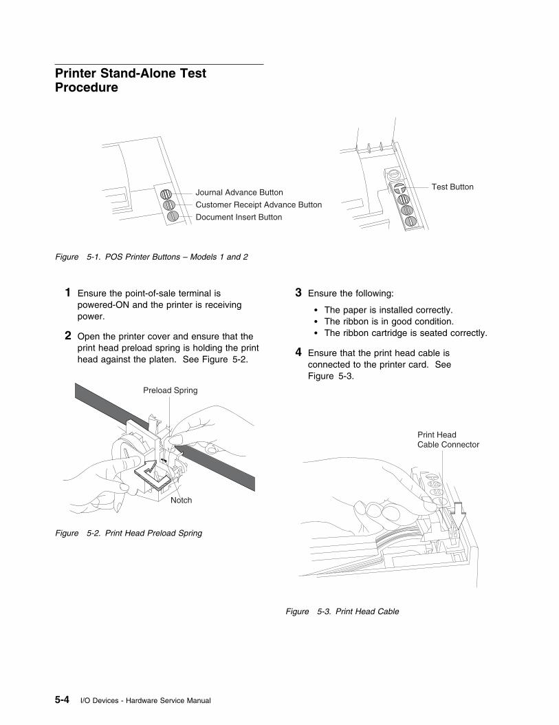
Printer Stand-Alone TestProcedure
Journal Advance Button
Customer Receipt Advance Button
Document Insert Button
Test Button
Figure 5-1. POS Printer Buttons – Models 1 and 2
1 Ensure the point-of-sale terminal ispowered-ON and the printer is receivingpower.
2 Open the printer cover and ensure that theprint head preload spring is holding the printhead against the platen. See Figure 5-2.
Preload Spring
Notch
Figure 5-2. Print Head Preload Spring
3 Ensure the following:
� The paper is installed correctly.� The ribbon is in good condition.� The ribbon cartridge is seated correctly.
4 Ensure that the print head cable isconnected to the printer card. SeeFigure 5-3.
Print HeadCable Connector
Figure 5-3. Print Head Cable
5-4 I/O Devices - Hardware Service Manual
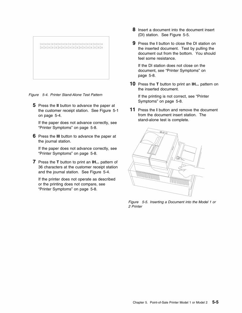
Figure 5-4. Printer Stand-Alone Test Pattern
5 Press the II button to advance the paper atthe customer receipt station. See Figure 5-1on page 5-4.
If the paper does not advance correctly, see“Printer Symptoms” on page 5-8.
6 Press the III button to advance the paper atthe journal station.
If the paper does not advance correctly, see“Printer Symptoms” on page 5-8.
7 Press the T button to print an IH... pattern of36 characters at the customer receipt stationand the journal station. See Figure 5-4.
If the printer does not operate as describedor the printing does not compare, see“Printer Symptoms” on page 5-8.
8 Insert a document into the document insert(DI) station. See Figure 5-5.
9 Press the I button to close the DI station onthe inserted document. Test by pulling thedocument out from the bottom. You shouldfeel some resistance.
If the DI station does not close on thedocument, see “Printer Symptoms” onpage 5-8.
10 Press the T button to print an IH... pattern onthe inserted document.
If the printing is not correct, see “PrinterSymptoms” on page 5-8.
11 Press the I button and remove the documentfrom the document insert station. Thestand-alone test is complete.
Figure 5-5. Inserting a Document into the Model 1 or2 Printer
Chapter 5. Point-of-Sale Printer Model 1 or Model 2 5-5
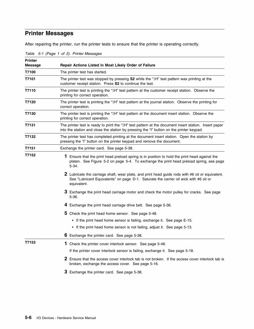
Printer Messages
After repairing the printer, run the printer tests to ensure that the printer is operating correctly.
Table 5-1 (Page 1 of 2). Printer Messages
PrinterMessage
Repair Actions Listed in Most Likely Order of Failure
T7100 The printer test has started.
T7101 The printer test was stopped by pressing S2 while the “IH” test pattern was printing at thecustomer receipt station. Press S2 to continue the test.
T7110 The printer test is printing the “IH” test pattern at the customer receipt station. Observe theprinting for correct operation.
T7120 The printer test is printing the “IH” test pattern at the journal station. Observe the printing forcorrect operation.
T7130 The printer test is printing the “IH” test pattern at the document insert station. Observe theprinting for correct operation.
T7131 The printer test is ready to print the “IH” test pattern at the document insert station. Insert paperinto the station and close the station by pressing the “I” button on the printer keypad.
T7132 The printer test has completed printing at the document insert station. Open the station bypressing the “I” button on the printer keypad and remove the document.
T7151 Exchange the printer card. See page 5-38.
T7152 1 Ensure that the print head preload spring is in position to hold the print head against theplaten. See Figure 5-2 on page 5-4. To exchange the print head preload spring, see page5-34.
2 Lubricate the carriage shaft, wear plate, and print head guide rods with #6 oil or equivalent.See “Lubricant Equivalents” on page D-1. Saturate the carrier oil wick with #6 oil orequivalent.
3 Exchange the print head carriage motor and check the motor pulley for cracks. See page5-36.
4 Exchange the print head carriage drive belt. See page 5-36.
5 Check the print head home sensor. See page 5-48.
� If the print head home sensor is failing, exchange it. See page E-15.
� If the print head home sensor is not failing, adjust it. See page 5-13.
6 Exchange the printer card. See page 5-38.
T7153 1 Check the printer cover interlock sensor. See page 5-48.
If the printer cover interlock sensor is failing, exchange it. See page 5-18.
2 Ensure that the access cover interlock tab is not broken. If the access cover interlock tab isbroken, exchange the access cover. See page 5-16.
3 Exchange the printer card. See page 5-38.
5-6 I/O Devices - Hardware Service Manual

Table 5-1 (Page 2 of 2). Printer Messages
PrinterMessage
Repair Actions Listed in Most Likely Order of Failure
T7154 1 Check the journal paper ribbon drive motor and belt. Pressing III on the printer keypad,which rotates the journal paper take-up spool, indicates the journal paper is not jammed orloaded incorrectly.
2 Check the journal paper motion emitter sensor. See page 5-48.
If the journal paper motion emitter sensor is failing, exchange it. See page 5-21.
3 Ensure that the journal paper motion emitter shaft rotates freely.
4 Exchange the printer card. See page 5-38.
T7155 1 Exchange the keypad. See page 5-27.
2 Exchange the printer card. See page 5-38.
T7156 1 Check the document insert paper sensor. See page 5-48.
If the document insert paper sensor is failing, exchange it. See page E-13.
2 Exchange the printer card. See page 5-38.
T7157 1 Remove paper or other obstructions from the document insert paper sensor.
2 Check the document insert paper sensor. See page 5-48.
If the document insert paper sensor is failing, exchange it. See page E-13.
3 Exchange the document insert paper guide. See page 5-19.
4 Exchange the platen. See page 5-28.
5 Exchange the printer card. See page 5-38.
T7158 1 Exchange the keypad. See page 5-27.
2 Exchange the printer card. See page 5-38.
W304 Exchange the printer card. See page 5-38.
W305 1 Ensure that the print head preload spring is in position to hold the print head against theplaten. See Figure 5-2 on page 5-4. To exchange the print head preload spring, see page5-34.
2 Lubricate the carriage shaft, wear plate and print head guide rods with #6 oil or equivalent.See “Lubricant Equivalents” on page D-1. Saturate the carrier oil wick with #6 oil.
3 Exchange the print head carriage motor and check the motor pulley for cracks. See page5-36.
4 Exchange the print head carriage drive belt. See page 5-36.
5 Check the print head home sensor. See page 5-48.
� If the print head home sensor is failing, exchange it. See page E-15.
� If the print head home sensor is not failing, adjust it. See page 5-13.
6 Exchange the printer card. See page 5-38.
Chapter 5. Point-of-Sale Printer Model 1 or Model 2 5-7
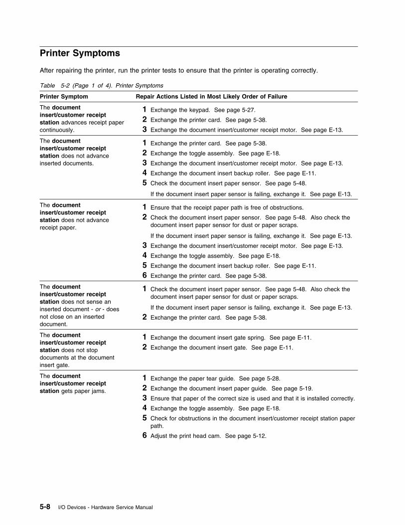
Printer Symptoms
After repairing the printer, run the printer tests to ensure that the printer is operating correctly.
Table 5-2 (Page 1 of 4). Printer Symptoms
Printer Symptom Repair Actions Listed in Most Likely Order of Failure
The documentinsert/customer receiptstation advances receipt papercontinuously.
1 Exchange the keypad. See page 5-27.
2 Exchange the printer card. See page 5-38.
3 Exchange the document insert/customer receipt motor. See page E-13.
The documentinsert/customer receiptstation does not advanceinserted documents.
1 Exchange the printer card. See page 5-38.
2 Exchange the toggle assembly. See page E-18.
3 Exchange the document insert/customer receipt motor. See page E-13.
4 Exchange the document insert backup roller. See page E-11.
5 Check the document insert paper sensor. See page 5-48.
If the document insert paper sensor is failing, exchange it. See page E-13.
The documentinsert/customer receiptstation does not advancereceipt paper.
1 Ensure that the receipt paper path is free of obstructions.
2 Check the document insert paper sensor. See page 5-48. Also check thedocument insert paper sensor for dust or paper scraps.
If the document insert paper sensor is failing, exchange it. See page E-13.
3 Exchange the document insert/customer receipt motor. See page E-13.
4 Exchange the toggle assembly. See page E-18.
5 Exchange the document insert backup roller. See page E-11.
6 Exchange the printer card. See page 5-38.
The documentinsert/customer receiptstation does not sense aninserted document - or - doesnot close on an inserteddocument.
1 Check the document insert paper sensor. See page 5-48. Also check thedocument insert paper sensor for dust or paper scraps.
If the document insert paper sensor is failing, exchange it. See page E-13.
2 Exchange the printer card. See page 5-38.
The documentinsert/customer receiptstation does not stopdocuments at the documentinsert gate.
1 Exchange the document insert gate spring. See page E-11.
2 Exchange the document insert gate. See page E-11.
The documentinsert/customer receiptstation gets paper jams.
1 Exchange the paper tear guide. See page 5-28.
2 Exchange the document insert paper guide. See page 5-19.
3 Ensure that paper of the correct size is used and that it is installed correctly.
4 Exchange the toggle assembly. See page E-18.
5 Check for obstructions in the document insert/customer receipt station paperpath.
6 Adjust the print head cam. See page 5-12.
5-8 I/O Devices - Hardware Service Manual
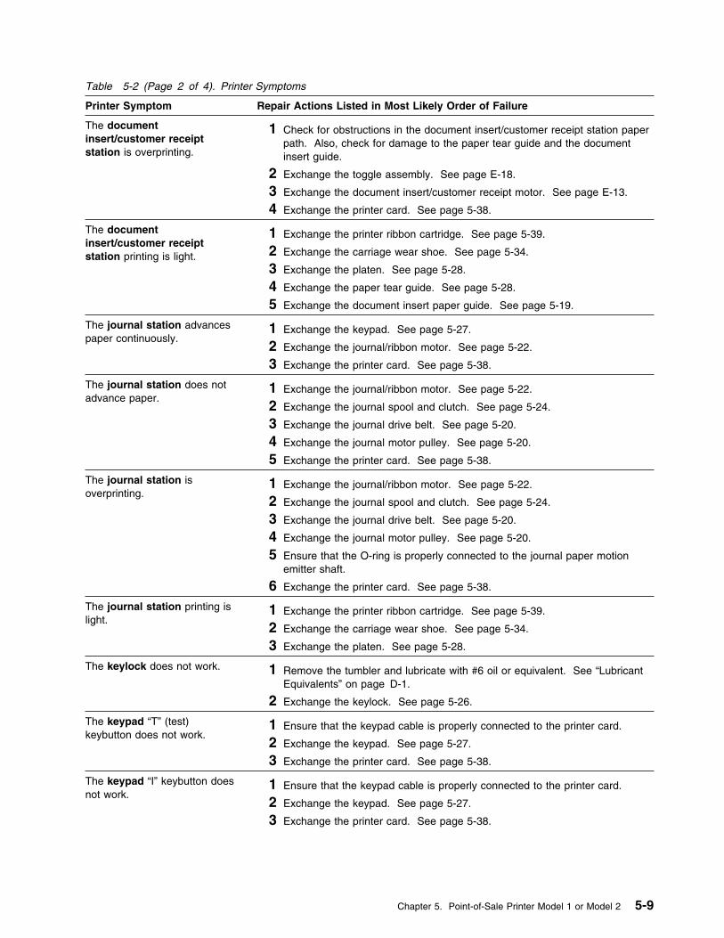
Table 5-2 (Page 2 of 4). Printer Symptoms
Printer Symptom Repair Actions Listed in Most Likely Order of Failure
The documentinsert/customer receiptstation is overprinting.
1 Check for obstructions in the document insert/customer receipt station paperpath. Also, check for damage to the paper tear guide and the documentinsert guide.
2 Exchange the toggle assembly. See page E-18.
3 Exchange the document insert/customer receipt motor. See page E-13.
4 Exchange the printer card. See page 5-38.
The documentinsert/customer receiptstation printing is light.
1 Exchange the printer ribbon cartridge. See page 5-39.
2 Exchange the carriage wear shoe. See page 5-34.
3 Exchange the platen. See page 5-28.
4 Exchange the paper tear guide. See page 5-28.
5 Exchange the document insert paper guide. See page 5-19.
The journal station advancespaper continuously.
1 Exchange the keypad. See page 5-27.
2 Exchange the journal/ribbon motor. See page 5-22.
3 Exchange the printer card. See page 5-38.
The journal station does notadvance paper.
1 Exchange the journal/ribbon motor. See page 5-22.
2 Exchange the journal spool and clutch. See page 5-24.
3 Exchange the journal drive belt. See page 5-20.
4 Exchange the journal motor pulley. See page 5-20.
5 Exchange the printer card. See page 5-38.
The journal station isoverprinting.
1 Exchange the journal/ribbon motor. See page 5-22.
2 Exchange the journal spool and clutch. See page 5-24.
3 Exchange the journal drive belt. See page 5-20.
4 Exchange the journal motor pulley. See page 5-20.
5 Ensure that the O-ring is properly connected to the journal paper motionemitter shaft.
6 Exchange the printer card. See page 5-38.
The journal station printing islight.
1 Exchange the printer ribbon cartridge. See page 5-39.
2 Exchange the carriage wear shoe. See page 5-34.
3 Exchange the platen. See page 5-28.
The keylock does not work. 1 Remove the tumbler and lubricate with #6 oil or equivalent. See “LubricantEquivalents” on page D-1.
2 Exchange the keylock. See page 5-26.
The keypad “T” (test)keybutton does not work.
1 Ensure that the keypad cable is properly connected to the printer card.
2 Exchange the keypad. See page 5-27.
3 Exchange the printer card. See page 5-38.
The keypad “I” keybutton doesnot work.
1 Ensure that the keypad cable is properly connected to the printer card.
2 Exchange the keypad. See page 5-27.
3 Exchange the printer card. See page 5-38.
Chapter 5. Point-of-Sale Printer Model 1 or Model 2 5-9

Table 5-2 (Page 3 of 4). Printer Symptoms
Printer Symptom Repair Actions Listed in Most Likely Order of Failure
The keypad “II” keybutton doesnot work.
1 Ensure that the keypad cable is properly connected to the printer card.
2 Exchange the keypad. See page 5-27.
3 Exchange the printer card. See page 5-38.
The keypad “III” keybuttondoes not work.
1 Ensure that the keypad cable is properly connected to the printer card.
2 Exchange the keypad. See page 5-27.
3 Exchange the printer card. See page 5-38.
All keypad keybuttons fail towork.
1 Ensure that the keypad cable is properly connected to the printer card.
2 Exchange the keypad. See page 5-27.
3 Exchange the printer card. See page 5-38.
The margins are not correct. 1 Check the print head home sensor. See page 5-48.� If the print head home sensor is failing, exchange it. See page E-15.� If the print head home sensor is not failing, adjust it. See page 5-13.
2 Ensure that the print head carriage motor pulley is functioning properly. See5-37. Lubricate the carriage shaft and print head guide rods with #6 oil orequivalent. See “Lubricant Equivalents” on page D-1. Saturate the carriageoil wick with #6 oil or equivalent.
3 Ensure that the carriage drive belt and belt spring assembly is functioningproperly.
4 Adjust or exchange the print head cam. See page 5-12.
Printed characters are light. 1 Exchange the ribbon cartridge after checking the ribbon drive shaft to ensurethat the ribbon is advancing properly. See page 5-39.
2 Clean the print head. If this fails to correct the symptom, exchange the printhead. See page 5-30.
3 Ensure that the print head preload spring is in position to hold the print headagainst the platen. To exchange the print head preload spring, see page5-34.
4 Exchange the journal/ribbon motor. See page 5-22.
5 Exchange the print head carriage assembly. See page 5-32.
6 Exchange the platen. See page 5-28.
7 Exchange the carriage wear shoe. See page 5-34.
8 Exchange the ribbon drive shaft. See page E-16.
Printed characters aremissing.
1 Ensure that the printer ribbon cartridge is properly seated.
2 Clean the print head. If this fails to correct the symptom, exchange the printhead. See page 5-30.
3 Exchange the printer card. See page 5-38.
4 Exchange the print head carriage drive belt. See page 5-36.
5 Exchange the print head carriage motor. See page 5-36.
Printed characters are notspaced correctly.
1 Exchange the print head carriage drive belt. See page 5-36.
2 Exchange the printer card. See page 5-38.
3 Exchange the print head carriage motor. See page 5-36.
5-10 I/O Devices - Hardware Service Manual
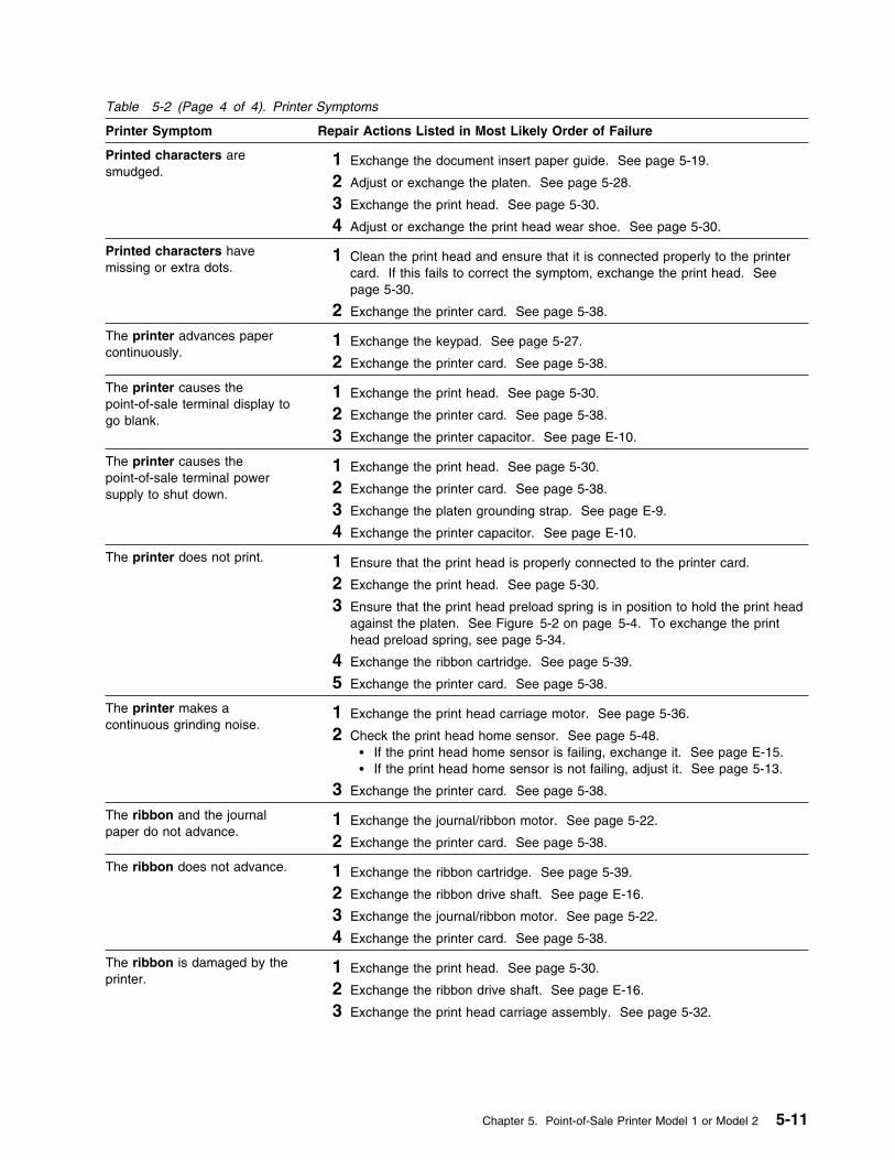
Table 5-2 (Page 4 of 4). Printer Symptoms
Printer Symptom Repair Actions Listed in Most Likely Order of Failure
Printed characters aresmudged.
1 Exchange the document insert paper guide. See page 5-19.
2 Adjust or exchange the platen. See page 5-28.
3 Exchange the print head. See page 5-30.
4 Adjust or exchange the print head wear shoe. See page 5-30.
Printed characters havemissing or extra dots.
1 Clean the print head and ensure that it is connected properly to the printercard. If this fails to correct the symptom, exchange the print head. Seepage 5-30.
2 Exchange the printer card. See page 5-38.
The printer advances papercontinuously.
1 Exchange the keypad. See page 5-27.
2 Exchange the printer card. See page 5-38.
The printer causes thepoint-of-sale terminal display togo blank.
1 Exchange the print head. See page 5-30.
2 Exchange the printer card. See page 5-38.
3 Exchange the printer capacitor. See page E-10.
The printer causes thepoint-of-sale terminal powersupply to shut down.
1 Exchange the print head. See page 5-30.
2 Exchange the printer card. See page 5-38.
3 Exchange the platen grounding strap. See page E-9.
4 Exchange the printer capacitor. See page E-10.
The printer does not print. 1 Ensure that the print head is properly connected to the printer card.
2 Exchange the print head. See page 5-30.
3 Ensure that the print head preload spring is in position to hold the print headagainst the platen. See Figure 5-2 on page 5-4. To exchange the printhead preload spring, see page 5-34.
4 Exchange the ribbon cartridge. See page 5-39.
5 Exchange the printer card. See page 5-38.
The printer makes acontinuous grinding noise.
1 Exchange the print head carriage motor. See page 5-36.
2 Check the print head home sensor. See page 5-48.� If the print head home sensor is failing, exchange it. See page E-15.� If the print head home sensor is not failing, adjust it. See page 5-13.
3 Exchange the printer card. See page 5-38.
The ribbon and the journalpaper do not advance.
1 Exchange the journal/ribbon motor. See page 5-22.
2 Exchange the printer card. See page 5-38.
The ribbon does not advance. 1 Exchange the ribbon cartridge. See page 5-39.
2 Exchange the ribbon drive shaft. See page E-16.
3 Exchange the journal/ribbon motor. See page 5-22.
4 Exchange the printer card. See page 5-38.
The ribbon is damaged by theprinter.
1 Exchange the print head. See page 5-30.
2 Exchange the ribbon drive shaft. See page E-16.
3 Exchange the print head carriage assembly. See page 5-32.
Chapter 5. Point-of-Sale Printer Model 1 or Model 2 5-11
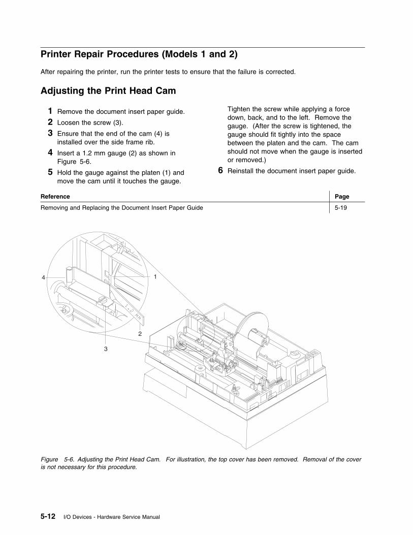
Printer Repair Procedures (Models 1 and 2)
After repairing the printer, run the printer tests to ensure that the failure is corrected.
Adjusting the Print Head Cam
1 Remove the document insert paper guide.
2 Loosen the screw (3).
3 Ensure that the end of the cam (4) isinstalled over the side frame rib.
4 Insert a 1.2 mm gauge (2) as shown inFigure 5-6.
5 Hold the gauge against the platen (1) andmove the cam until it touches the gauge.
Tighten the screw while applying a forcedown, back, and to the left. Remove thegauge. (After the screw is tightened, thegauge should fit tightly into the spacebetween the platen and the cam. The camshould not move when the gauge is insertedor removed.)
6 Reinstall the document insert paper guide.
Reference Page
Removing and Replacing the Document Insert Paper Guide 5-19
1
2
3
4
Figure 5-6. Adjusting the Print Head Cam. For illustration, the top cover has been removed. Removal of the coveris not necessary for this procedure.
5-12 I/O Devices - Hardware Service Manual
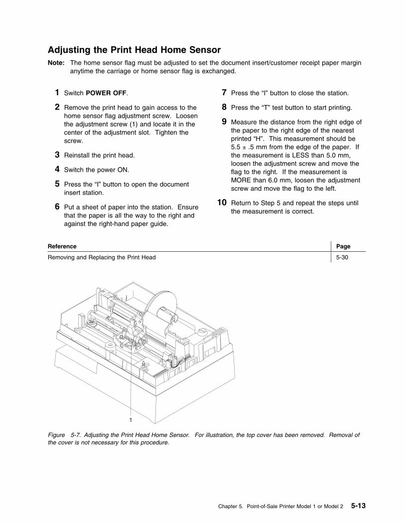
Adjusting the Print Head Home SensorNote: The home sensor flag must be adjusted to set the document insert/customer receipt paper margin
anytime the carriage or home sensor flag is exchanged.
1 Switch POWER OFF.
2 Remove the print head to gain access to thehome sensor flag adjustment screw. Loosenthe adjustment screw (1) and locate it in thecenter of the adjustment slot. Tighten thescrew.
3 Reinstall the print head.
4 Switch the power ON.
5 Press the “I” button to open the documentinsert station.
6 Put a sheet of paper into the station. Ensurethat the paper is all the way to the right andagainst the right-hand paper guide.
7 Press the “I” button to close the station.
8 Press the “T” test button to start printing.
9 Measure the distance from the right edge ofthe paper to the right edge of the nearestprinted “H”. This measurement should be5.5 ± .5 mm from the edge of the paper. Ifthe measurement is LESS than 5.0 mm,loosen the adjustment screw and move theflag to the right. If the measurement isMORE than 6.0 mm, loosen the adjustmentscrew and move the flag to the left.
10 Return to Step 5 and repeat the steps untilthe measurement is correct.
Reference Page
Removing and Replacing the Print Head 5-30
1
Figure 5-7. Adjusting the Print Head Home Sensor. For illustration, the top cover has been removed. Removal ofthe cover is not necessary for this procedure.
Chapter 5. Point-of-Sale Printer Model 1 or Model 2 5-13
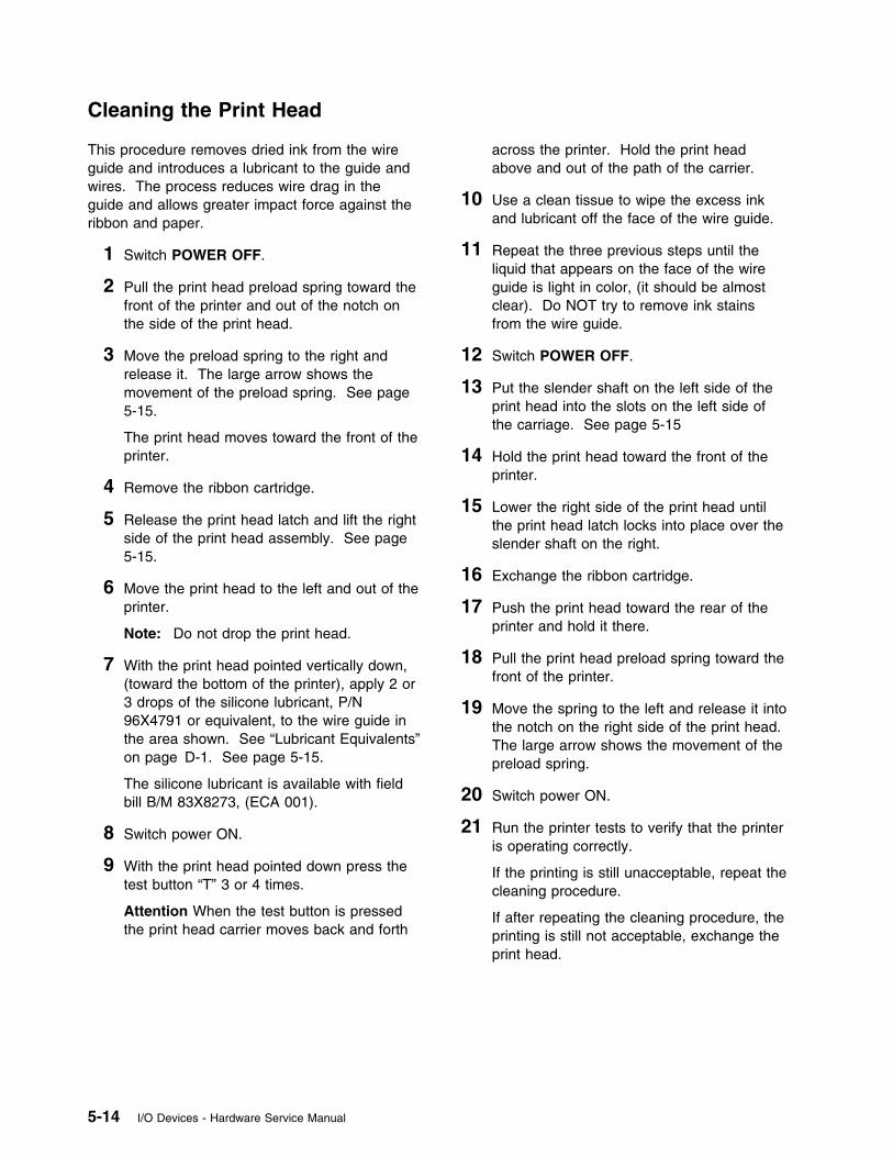
Cleaning the Print Head
This procedure removes dried ink from the wireguide and introduces a lubricant to the guide andwires. The process reduces wire drag in theguide and allows greater impact force against theribbon and paper.
1 Switch POWER OFF.
2 Pull the print head preload spring toward thefront of the printer and out of the notch onthe side of the print head.
3 Move the preload spring to the right andrelease it. The large arrow shows themovement of the preload spring. See page5-15.
The print head moves toward the front of theprinter.
4 Remove the ribbon cartridge.
5 Release the print head latch and lift the rightside of the print head assembly. See page5-15.
6 Move the print head to the left and out of theprinter.
Note: Do not drop the print head.
7 With the print head pointed vertically down,(toward the bottom of the printer), apply 2 or3 drops of the silicone lubricant, P/N96X4791 or equivalent, to the wire guide inthe area shown. See “Lubricant Equivalents”on page D-1. See page 5-15.
The silicone lubricant is available with fieldbill B/M 83X8273, (ECA 001).
8 Switch power ON.
9 With the print head pointed down press thetest button “T” 3 or 4 times.
Attention When the test button is pressedthe print head carrier moves back and forth
across the printer. Hold the print headabove and out of the path of the carrier.
10 Use a clean tissue to wipe the excess inkand lubricant off the face of the wire guide.
11 Repeat the three previous steps until theliquid that appears on the face of the wireguide is light in color, (it should be almostclear). Do NOT try to remove ink stainsfrom the wire guide.
12 Switch POWER OFF.
13 Put the slender shaft on the left side of theprint head into the slots on the left side ofthe carriage. See page 5-15
14 Hold the print head toward the front of theprinter.
15 Lower the right side of the print head untilthe print head latch locks into place over theslender shaft on the right.
16 Exchange the ribbon cartridge.
17 Push the print head toward the rear of theprinter and hold it there.
18 Pull the print head preload spring toward thefront of the printer.
19 Move the spring to the left and release it intothe notch on the right side of the print head.The large arrow shows the movement of thepreload spring.
20 Switch power ON.
21 Run the printer tests to verify that the printeris operating correctly.
If the printing is still unacceptable, repeat thecleaning procedure.
If after repeating the cleaning procedure, theprinting is still not acceptable, exchange theprint head.
5-14 I/O Devices - Hardware Service Manual
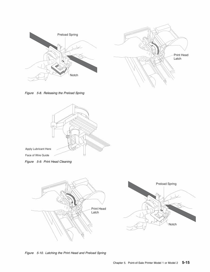
Preload Spring
Notch
Print HeadLatch
Figure 5-8. Releasing the Preload Spring
Apply Lubricant Here
Face of Wire Guide
Figure 5-9. Print Head Cleaning
Preload Spring
Notch
Print HeadLatch
Figure 5-10. Latching the Print Head and Preload Spring
Chapter 5. Point-of-Sale Printer Model 1 or Model 2 5-15
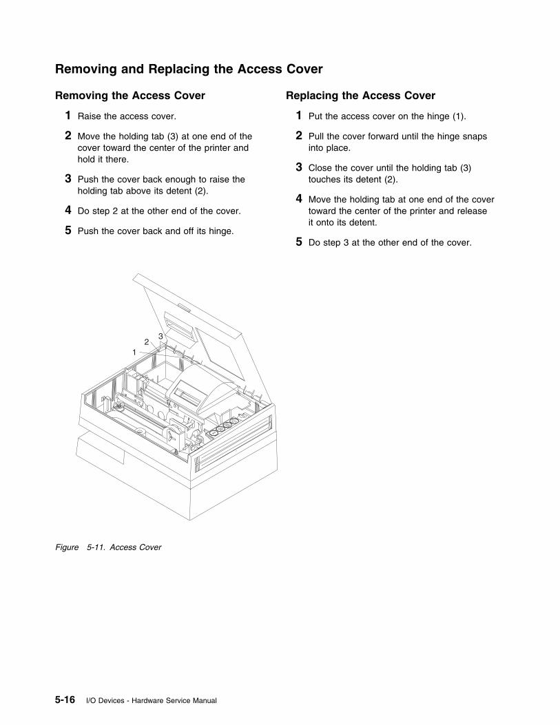
Removing and Replacing the Access Cover
Removing the Access Cover
1 Raise the access cover.
2 Move the holding tab (3) at one end of thecover toward the center of the printer andhold it there.
3 Push the cover back enough to raise theholding tab above its detent (2).
4 Do step 2 at the other end of the cover.
5 Push the cover back and off its hinge.
Replacing the Access Cover
1 Put the access cover on the hinge (1).
2 Pull the cover forward until the hinge snapsinto place.
3 Close the cover until the holding tab (3)touches its detent (2).
4 Move the holding tab at one end of the covertoward the center of the printer and releaseit onto its detent.
5 Do step 3 at the other end of the cover.
12
3
Figure 5-11. Access Cover
5-16 I/O Devices - Hardware Service Manual

Removing and Replacing the Bottom Cover
Removing the Bottom Cover
1 Disconnect the cable if present.
2 Loosen the thumbscrew (1).
3 Move the bottom cover holding tabs (2)toward the center of the printer to releasethem, and at the same time, pull the bottomcover off the printer.
Replacing the Bottom Cover
1 Align the holding tabs (2) over their slots.
The grounding straps should be centered inthe hole for the thumbscrew.
2 Push in on the cover until the tabs lock intoplace.
3 Tighten the thumbscrew (1).
1 2
2
2
Figure 5-12. Bottom Cover
Chapter 5. Point-of-Sale Printer Model 1 or Model 2 5-17
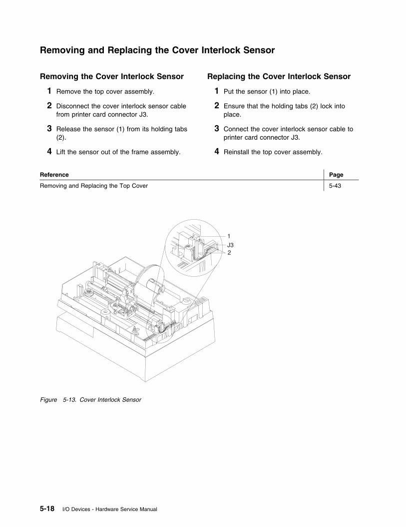
Removing and Replacing the Cover Interlock Sensor
Removing the Cover Interlock Sensor
1 Remove the top cover assembly.
2 Disconnect the cover interlock sensor cablefrom printer card connector J3.
3 Release the sensor (1) from its holding tabs(2).
4 Lift the sensor out of the frame assembly.
Replacing the Cover Interlock Sensor
1 Put the sensor (1) into place.
2 Ensure that the holding tabs (2) lock intoplace.
3 Connect the cover interlock sensor cable toprinter card connector J3.
4 Reinstall the top cover assembly.
Reference Page
Removing and Replacing the Top Cover 5-43
1
2J3
Figure 5-13. Cover Interlock Sensor
5-18 I/O Devices - Hardware Service Manual
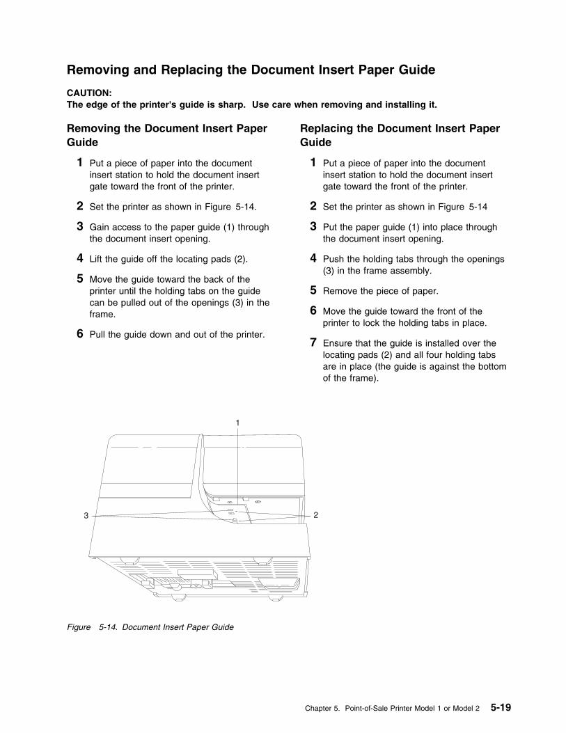
Removing and Replacing the Document Insert Paper Guide
CAUTION:The edge of the printer's guide is sharp. Use care when removing and installing it.
Removing the Document Insert PaperGuide
1 Put a piece of paper into the documentinsert station to hold the document insertgate toward the front of the printer.
2 Set the printer as shown in Figure 5-14.
3 Gain access to the paper guide (1) throughthe document insert opening.
4 Lift the guide off the locating pads (2).
5 Move the guide toward the back of theprinter until the holding tabs on the guidecan be pulled out of the openings (3) in theframe.
6 Pull the guide down and out of the printer.
Replacing the Document Insert PaperGuide
1 Put a piece of paper into the documentinsert station to hold the document insertgate toward the front of the printer.
2 Set the printer as shown in Figure 5-14
3 Put the paper guide (1) into place throughthe document insert opening.
4 Push the holding tabs through the openings(3) in the frame assembly.
5 Remove the piece of paper.
6 Move the guide toward the front of theprinter to lock the holding tabs in place.
7 Ensure that the guide is installed over thelocating pads (2) and all four holding tabsare in place (the guide is against the bottomof the frame).
1
23
Figure 5-14. Document Insert Paper Guide
Chapter 5. Point-of-Sale Printer Model 1 or Model 2 5-19
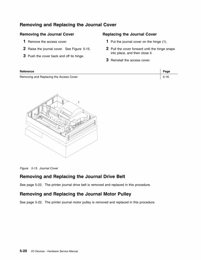
Removing and Replacing the Journal Cover
Removing the Journal Cover
1 Remove the access cover.
2 Raise the journal cover. See Figure 5-15.
3 Push the cover back and off its hinge.
Replacing the Journal Cover
1 Put the journal cover on the hinge (1).
2 Pull the cover forward until the hinge snapsinto place, and then close it.
3 Reinstall the access cover.
Reference Page
Removing and Replacing the Access Cover 5-16
1
Figure 5-15. Journal Cover
Removing and Replacing the Journal Drive Belt
See page 5-22. The printer journal drive belt is removed and replaced in this procedure.
Removing and Replacing the Journal Motor Pulley
See page 5-22. The printer journal motor pulley is removed and replaced in this procedure.
5-20 I/O Devices - Hardware Service Manual
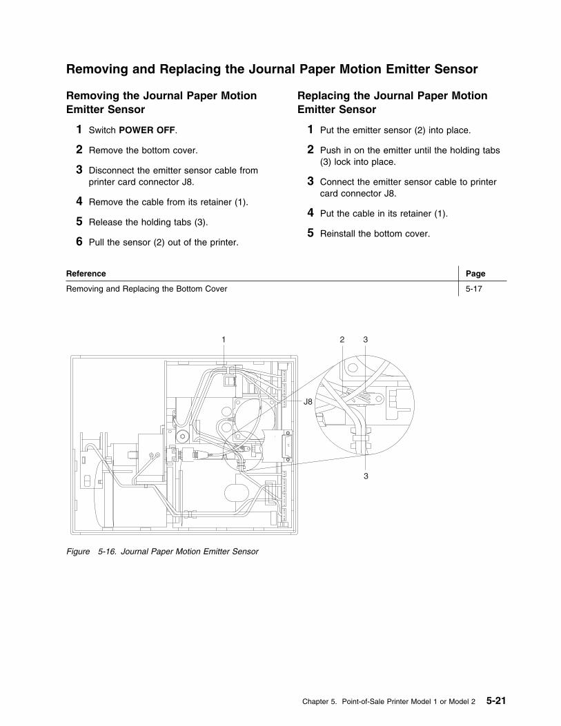
Removing and Replacing the Journal Paper Motion Emitter Sensor
Removing the Journal Paper MotionEmitter Sensor
1 Switch POWER OFF.
2 Remove the bottom cover.
3 Disconnect the emitter sensor cable fromprinter card connector J8.
4 Remove the cable from its retainer (1).
5 Release the holding tabs (3).
6 Pull the sensor (2) out of the printer.
Replacing the Journal Paper MotionEmitter Sensor
1 Put the emitter sensor (2) into place.
2 Push in on the emitter until the holding tabs(3) lock into place.
3 Connect the emitter sensor cable to printercard connector J8.
4 Put the cable in its retainer (1).
5 Reinstall the bottom cover.
Reference Page
Removing and Replacing the Bottom Cover 5-17
J8
1 2 3
3
Figure 5-16. Journal Paper Motion Emitter Sensor
Chapter 5. Point-of-Sale Printer Model 1 or Model 2 5-21

Removing and Replacing the Journal/Ribbon Motor
Removing the Journal/Ribbon Motor
1 Take the belt off the journal paper spool.
2 Remove the bottom cover.
3 Release the ribbon drive shaft coupler (2) byremoving the C-clip (3).
4 Pull the coupler off the motor shaft.
5 Remove the belt from the drive motor pulley(1).
6 Remove the pulley from the motor shaft.
7 Disconnect the drive motor cable from printercard connector J11.
8 Remove the cable from its retainer (4).
9 Move the motor toward the side of theprinter and off its locating pad (5).
10 Pivot the motor toward the front of the printerand remove it from the printer.
Replacing the Journal/Ribbon Motor
1 Hold the drive motor toward the side of theprinter as you put it into place.
2 Move the motor to the right into its locatingpad (5).
3 Connect the motor cable to printer cardconnector J11.
4 Put the cable into its retainer (4).
5 Put the pulley (1) on the motor shaft.
6 Put the drive belt on the motor pulley and uptoward the journal paper spool.
7 Connect the ribbon drive shaft coupler (2) tothe motor shaft.
8 Attach the coupler to the shaft with the C-clip(3).
9 Put the drive belt on the journal paper spool.
10 Reinstall the bottom cover.
Reference Page
Removing and Replacing the Bottom Cover 5-17
5-22 I/O Devices - Hardware Service Manual
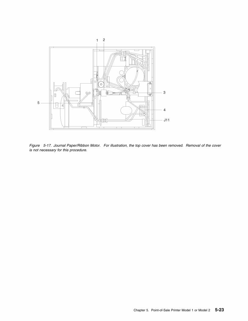
J11
1 2
3
4
5
Figure 5-17. Journal Paper/Ribbon Motor. For illustration, the top cover has been removed. Removal of the coveris not necessary for this procedure.
Chapter 5. Point-of-Sale Printer Model 1 or Model 2 5-23
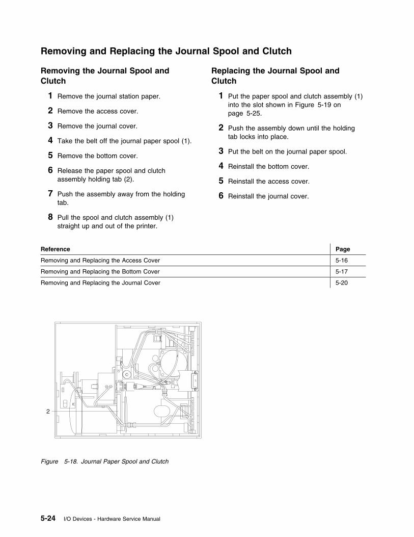
Removing and Replacing the Journal Spool and Clutch
Removing the Journal Spool andClutch
1 Remove the journal station paper.
2 Remove the access cover.
3 Remove the journal cover.
4 Take the belt off the journal paper spool (1).
5 Remove the bottom cover.
6 Release the paper spool and clutchassembly holding tab (2).
7 Push the assembly away from the holdingtab.
8 Pull the spool and clutch assembly (1)straight up and out of the printer.
Replacing the Journal Spool andClutch
1 Put the paper spool and clutch assembly (1)into the slot shown in Figure 5-19 onpage 5-25.
2 Push the assembly down until the holdingtab locks into place.
3 Put the belt on the journal paper spool.
4 Reinstall the bottom cover.
5 Reinstall the access cover.
6 Reinstall the journal cover.
Reference Page
Removing and Replacing the Access Cover 5-16
Removing and Replacing the Bottom Cover 5-17
Removing and Replacing the Journal Cover 5-20
2
Figure 5-18. Journal Paper Spool and Clutch
5-24 I/O Devices - Hardware Service Manual
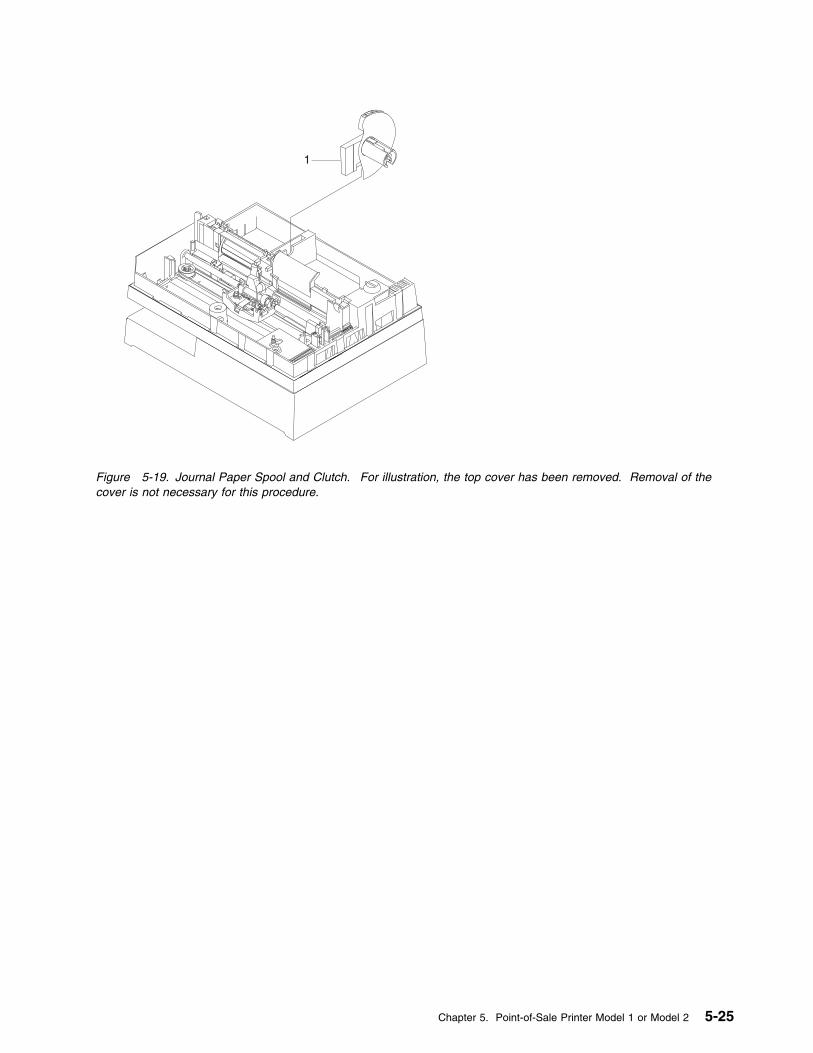
1
Figure 5-19. Journal Paper Spool and Clutch. For illustration, the top cover has been removed. Removal of thecover is not necessary for this procedure.
Chapter 5. Point-of-Sale Printer Model 1 or Model 2 5-25
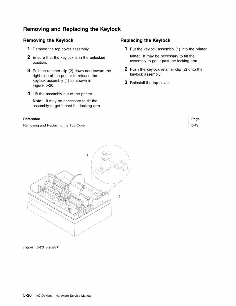
Removing and Replacing the Keylock
Removing the Keylock
1 Remove the top cover assembly.
2 Ensure that the keylock is in the unlockedposition.
3 Pull the retainer clip (2) down and toward theright side of the printer to release thekeylock assembly (1) as shown inFigure 5-20.
4 Lift the assembly out of the printer.
Note: It may be necessary to tilt theassembly to get it past the locking arm.
Replacing the Keylock
1 Put the keylock assembly (1) into the printer.
Note: It may be necessary to tilt theassembly to get it past the locking arm.
2 Push the keylock retainer clip (2) onto thekeylock assembly.
3 Reinstall the top cover.
Reference Page
Removing and Replacing the Top Cover 5-43
1
2
Figure 5-20. Keylock
5-26 I/O Devices - Hardware Service Manual

Removing and Replacing the Keypad
Removing the Keypad
1 Remove the top cover assembly.
2 Remove the ESD clip.
3 Peel the operator keypad off the coverassembly.
The pad is held to the cover withpeel-and-stick adhesive.
Replacing the Keypad
1 Clean the old glue off the top coverassembly with alcohol.
2 Put the cable through the slot in the cover.
3 Peel off the protective cover to expose theadhesive.
4 Press the new operator keypad in place.
5 Peel the clear protective cover off the top ofthe keypad.
6 Install the ESD clip.
7 Connect the keypad cable.
8 Reinstall the top cover.
Reference Page
Removing and Replacing the Top Cover 5-43
KeypadESD Clip
Figure 5-21. Keypad
Chapter 5. Point-of-Sale Printer Model 1 or Model 2 5-27
Removing and Replacing the Platen and Paper Tear Guide
Removing the Platen and Paper TearGuide
1 Remove the top cover assembly.
2 Remove the document insert paper guide.
3 Remove the paper from both print stations.
4 Put a piece of paper into the documentinsert station to hold the document insertgate toward the front of the printer.
5 Remove the platen retainers (1). SeeFigure 5-22 on page 5-29.
6 Hold the platen assembly at the journalstation and lift up until the top roller (6) canbe removed.
7 When the roller has been removed, lift theplaten straight up and out of the printer.
8 Remove the piece of paper from thedocument insert station.
9 Move the holding tabs (3) (back of theplaten) toward each other to release thepaper tear guide.
10 Push the tabs through the platen andremove the guide.
Replacing the Platen and Paper TearGuide
1 Put the paper tear guide on the platen withits holding tabs (3) as shown in Figure 5-22.Ensure that the sawtooth edge goes throughthe slot in the platen before the holding tabslock into place.
2 Put a piece of paper into the documentinsert station.
3 Turn the large toggle gear down. This keepsthe toggle assembly from interfering with thepaper tear guide when the platen is installed.
4 Move the receipt paper backup roller andspacers to the center of their shaft to ensurethat they do not interfere with the projectionson the bottom of the platen.
5 Lubricate the rubber boots (2) with silicongrease, P/N 265390. Put the boots into theirslots (4).
6 Push down on each end of the platenassembly until the boots are approximatelyhalfway down.
Note: Be careful to avoid damaging thepaper guides and journal bail.
7 Reinstall the top roller (6).
8 Continue to push down on each end of theplaten assembly until the boots are at thebottom of their slots. Ensure that the platenis parallel with the frame assembly at thepoints designated by (5). Also, ensure thatthe platen boots are seated correctly bypushing them down in front of and behindthe platen.
9 Reinstall the platen retainers (1). Hold theplaten in the journal paper path area androck the platen front to back several times.Push the platen back until the platencontacts the upper frame and then hold forone second.
10 Check to ensure that the platen groundingstrap is properly seated under the platen.See Figure E-8 on page E-9.
11 Remove the piece of paper.
12 Reinstall the top cover.
13 Reinstall the document insert paper guide.
14 Check the alignment between the platen andthe print head. See page 5-34.
Reference Page
Removing and Replacing the Document Insert Paper Guide 5-19
Removing and Replacing the Top Cover 5-43
5-28 I/O Devices - Hardware Service Manual
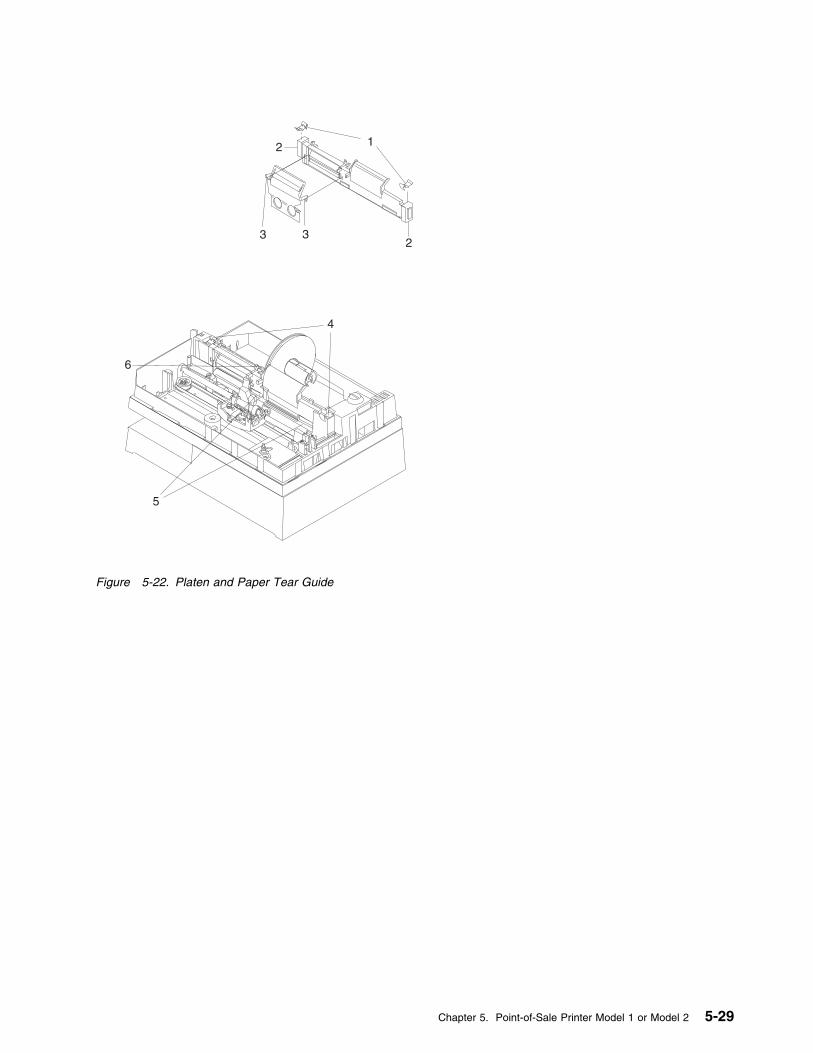
12
233
4
5
6
Figure 5-22. Platen and Paper Tear Guide
Chapter 5. Point-of-Sale Printer Model 1 or Model 2 5-29
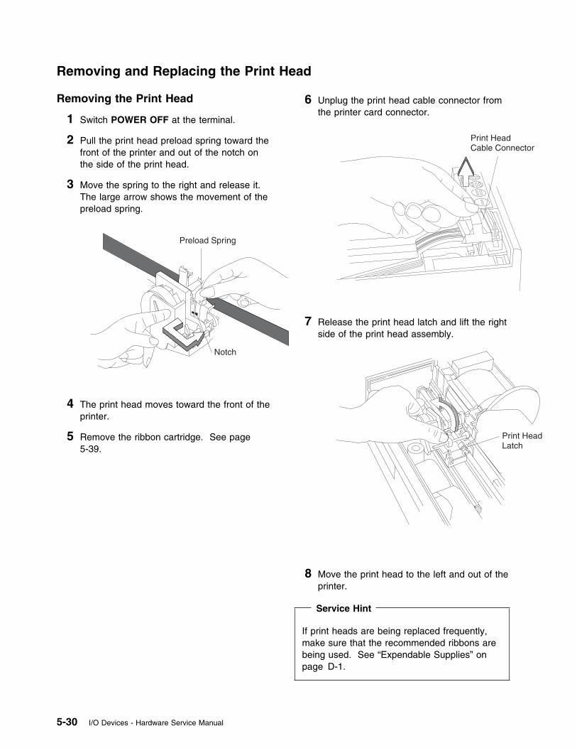
Removing and Replacing the Print Head
Removing the Print Head
1 Switch POWER OFF at the terminal.
2 Pull the print head preload spring toward thefront of the printer and out of the notch onthe side of the print head.
3 Move the spring to the right and release it.The large arrow shows the movement of thepreload spring.
Preload Spring
Notch
4 The print head moves toward the front of theprinter.
5 Remove the ribbon cartridge. See page5-39.
6 Unplug the print head cable connector fromthe printer card connector.
Print HeadCable Connector
7 Release the print head latch and lift the rightside of the print head assembly.
Print HeadLatch
8 Move the print head to the left and out of theprinter.
Service Hint
If print heads are being replaced frequently,make sure that the recommended ribbons arebeing used. See “Expendable Supplies” onpage D-1.
5-30 I/O Devices - Hardware Service Manual

Replacing the Print Head
1 Switch POWER OFF.
2 Put the slender shaft on the left side of theprint head into the slots on the left side ofthe carriage.
3 Hold the print head toward the front of theprinter.
4 Lower the right side of the print head untilthe print head latch locks into place over theslender shaft on the right.
Print HeadLatch
5 Plug the print head cable connector into theprinter card connector.
Print HeadCable Connector
6 Exchange the ribbon cartridge. See page5-40.
7 Push the print head toward the rear of theprinter and hold it there.
8 Pull the print head preload spring toward thefront of the printer.
9 Move the spring to the left and release it intothe notch on the right side of the print head.The large arrow shows the movement of thepreload spring.
Preload Spring
Notch
10 Switch power ON again.
11 Run the printer test to verify that the printhead is working correctly.
Chapter 5. Point-of-Sale Printer Model 1 or Model 2 5-31
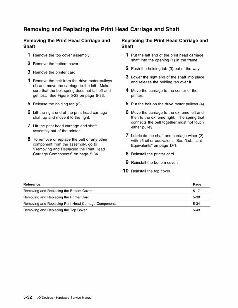
Removing and Replacing the Print Head Carriage and Shaft
Removing the Print Head Carriage andShaft
1 Remove the top cover assembly.
2 Remove the bottom cover.
3 Remove the printer card.
4 Remove the belt from the drive motor pulleys(4) and move the carriage to the left. Makesure that the belt spring does not fall off andget lost. See Figure 5-23 on page 5-33.
5 Release the holding tab (3).
6 Lift the right end of the print head carriageshaft up and move it to the right.
7 Lift the print head carriage and shaftassembly out of the printer.
8 To remove or replace the belt or any othercomponent from the assembly, go to“Removing and Replacing the Print HeadCarriage Components” on page 5-34.
Replacing the Print Head Carriage andShaft
1 Put the left end of the print head carriageshaft into the opening (1) in the frame.
2 Push the holding tab (3) out of the way.
3 Lower the right end of the shaft into placeand release the holding tab over it.
4 Move the carriage to the center of theprinter.
5 Put the belt on the drive motor pulleys (4).
6 Move the carriage to the extreme left andthen to the extreme right. The spring thatconnects the belt together must not toucheither pulley.
7 Lubricate the shaft and carriage wiper (2)with #6 oil or equivalent. See “LubricantEquivalents” on page D-1.
8 Reinstall the printer card.
9 Reinstall the bottom cover.
10 Reinstall the top cover.
Reference Page
Removing and Replacing the Bottom Cover 5-17
Removing and Replacing the Printer Card 5-38
Removing and Replacing Print Head Carriage Components 5-34
Removing and Replacing the Top Cover 5-43
5-32 I/O Devices - Hardware Service Manual
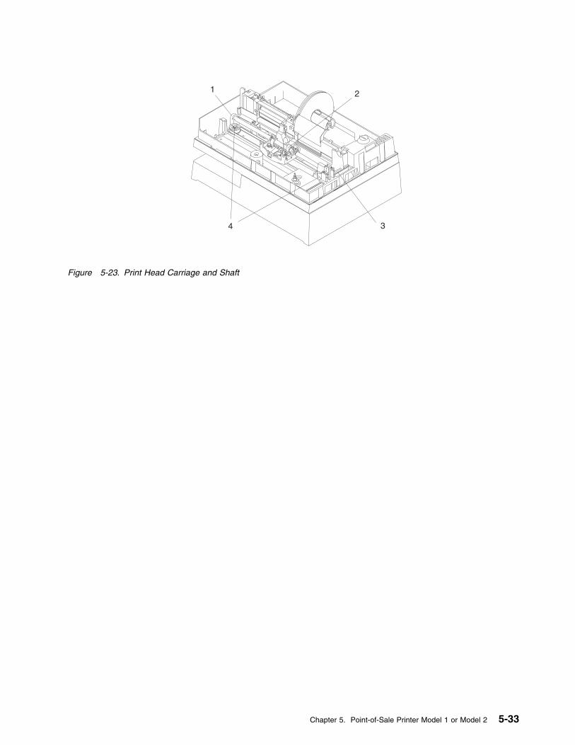
1 2
34
Figure 5-23. Print Head Carriage and Shaft
Chapter 5. Point-of-Sale Printer Model 1 or Model 2 5-33
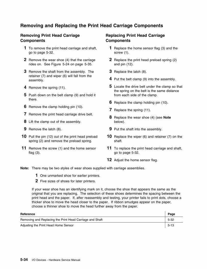
Removing and Replacing the Print Head Carriage Components
Removing Print Head CarriageComponents
1 To remove the print head carriage and shaft,go to page 5-32.
2 Remove the wear shoe (4) that the carriagerides on. See Figure 5-24 on page 5-35.
3 Remove the shaft from the assembly. Theretainer (7) and wiper (6) will fall from theassembly.
4 Remove the spring (11).
5 Push down on the belt clamp (9) and hold itthere.
6 Remove the clamp holding pin (10).
7 Remove the print head carriage drive belt.
8 Lift the clamp out of the assembly.
9 Remove the latch (8).
10 Pull the pin (12) out of the print head preloadspring (2) and remove the preload spring.
11 Remove the screw (1) and the home sensorflag (3).
Replacing Print Head CarriageComponents
1 Replace the home sensor flag (3) and thescrew (1).
2 Replace the print head preload spring (2)and pin (12).
3 Replace the latch (8).
4 Put the belt clamp (9) into the assembly.
5 Locate the drive belt under the clamp so thatthe spring on the belt is the same distancefrom each side of the clamp.
6 Replace the clamp holding pin (10).
7 Replace the spring (11).
8 Replace the wear shoe (4) (see Notebelow).
9 Put the shaft into the assembly.
10 Replace the wiper (6) and retainer (7) on theshaft.
11 To replace the print head carriage and shaft,go to page 5-32.
12 Adjust the home sensor flag.
Note: There may be two styles of wear shoes supplied with carriage assemblies.
1 One unmarked shoe for earlier printers.
2 Five sizes of shoes for later printers.
If your wear shoe has an identifying mark on it, choose the shoe that appears the same as theoriginal that you are replacing. The selection of these shoes determines the spacing between theprint head and the paper. If, after reassembly and testing, your printer fails to print dots, choose athicker shoe to move the head closer to the paper. If ribbon smudges appear on the paper,choose a thinner shoe to move the head further away from the paper.
Reference Page
Removing and Replacing the Print Head Carriage and Shaft 5-32
Adjusting the Print Head Home Sensor 5-13
5-34 I/O Devices - Hardware Service Manual
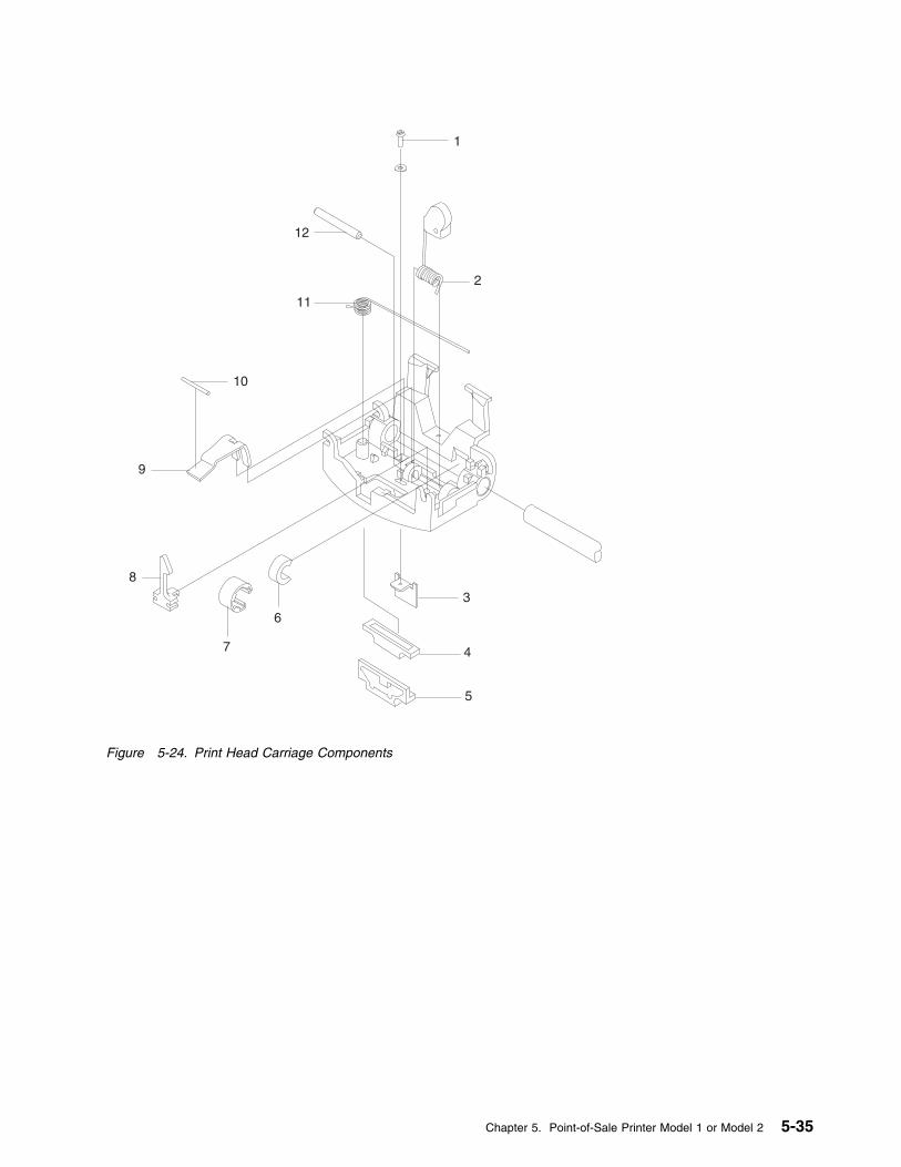
1
2
3
4
5
6
7
8
9
10
11
12
Figure 5-24. Print Head Carriage Components
Chapter 5. Point-of-Sale Printer Model 1 or Model 2 5-35
Removing and Replacing the Print Head Carriage Drive Belt
See page 5-34. The print head carriage drive belt is removed and replaced in this procedure.
Removing and Replacing the Print Head Carriage Motor
Removing the Print Head CarriageMotor
1 Remove the carriage drive belt from themotor pulley (1). See Figure 5-25 onpage 5-37.
2 Remove the bottom cover.
3 Disconnect the motor cable from printer cardconnector J10.
4 Remove the motor cable from its retainers(3).
5 Remove the motor screws (2).
6 Pull the carriage drive motor out the bottomof the printer.
Replacing the Print Head CarriageMotor
1 Put the carriage drive motor into place asshown in Figure 5-25 on page 5-37.
2 Reinstall the motor screws (2).
3 Put the motor cable into its retainers (3).
4 Connect the cable to printer card connectorJ10.
5 Move the carriage to the center of theprinter.
6 Put the drive belt on the motor pulley (1).
7 Move the carriage to the extreme left andthen to the extreme right. The spring thatconnects the belt must not touch eitherpulley.
8 Reinstall the bottom cover.
Reference Page
Removing and Replacing the Bottom Cover 5-17
5-36 I/O Devices - Hardware Service Manual
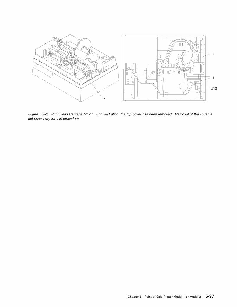
J10
1
2
3
Figure 5-25. Print Head Carriage Motor. For illustration, the top cover has been removed. Removal of the cover isnot necessary for this procedure.
Chapter 5. Point-of-Sale Printer Model 1 or Model 2 5-37
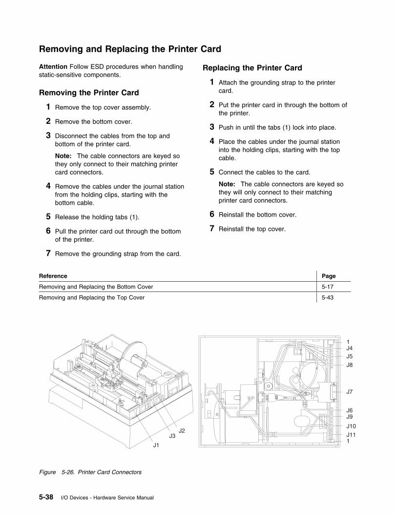
Removing and Replacing the Printer Card
Attention Follow ESD procedures when handlingstatic-sensitive components.
Removing the Printer Card
1 Remove the top cover assembly.
2 Remove the bottom cover.
3 Disconnect the cables from the top andbottom of the printer card.
Note: The cable connectors are keyed sothey only connect to their matching printercard connectors.
4 Remove the cables under the journal stationfrom the holding clips, starting with thebottom cable.
5 Release the holding tabs (1).
6 Pull the printer card out through the bottomof the printer.
7 Remove the grounding strap from the card.
Replacing the Printer Card
1 Attach the grounding strap to the printercard.
2 Put the printer card in through the bottom ofthe printer.
3 Push in until the tabs (1) lock into place.
4 Place the cables under the journal stationinto the holding clips, starting with the topcable.
5 Connect the cables to the card.
Note: The cable connectors are keyed sothey will only connect to their matchingprinter card connectors.
6 Reinstall the bottom cover.
7 Reinstall the top cover.
Reference Page
Removing and Replacing the Bottom Cover 5-17
Removing and Replacing the Top Cover 5-43
J1
J3J2
1J4J5
J8
J7
J6J9
J10
J111
Figure 5-26. Printer Card Connectors
5-38 I/O Devices - Hardware Service Manual
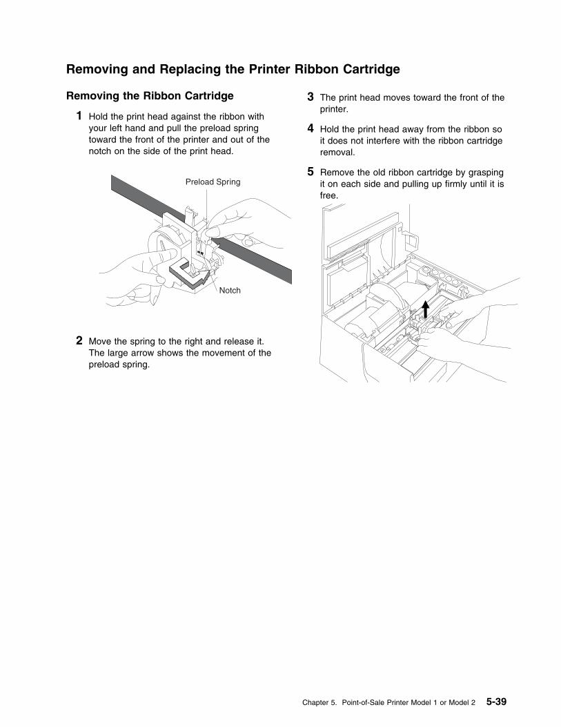
Removing and Replacing the Printer Ribbon Cartridge
Removing the Ribbon Cartridge
1 Hold the print head against the ribbon withyour left hand and pull the preload springtoward the front of the printer and out of thenotch on the side of the print head.
Preload Spring
Notch
2 Move the spring to the right and release it.The large arrow shows the movement of thepreload spring.
3 The print head moves toward the front of theprinter.
4 Hold the print head away from the ribbon soit does not interfere with the ribbon cartridgeremoval.
5 Remove the old ribbon cartridge by graspingit on each side and pulling up firmly until it isfree.
Chapter 5. Point-of-Sale Printer Model 1 or Model 2 5-39

Replacing the Ribbon Cartridge
Note: Use ribbon cartridge P/N 4483015 orequivalent. Failure to do so may affect print headlife and print quality. Replacing the ribboncartridge is the user’s responsibility.
1 Rotate the ribbon feed knob clockwise totake up any slack in the ribbon. The knob islocated on the top right side of the ribboncartridge.
2 Line up the groove in the front center of theribbon cartridge with the projection on theinside of the printer.
3 Press both ends of the ribbon cartridgestraight down while rotating the ribbon feedknob clockwise until the cartridge snaps intoplace.
4 Ensure that the ribbon is between the printhead and the two ribbon guides as shown inthe following figure.
Ribbon Guides
5-40 I/O Devices - Hardware Service Manual
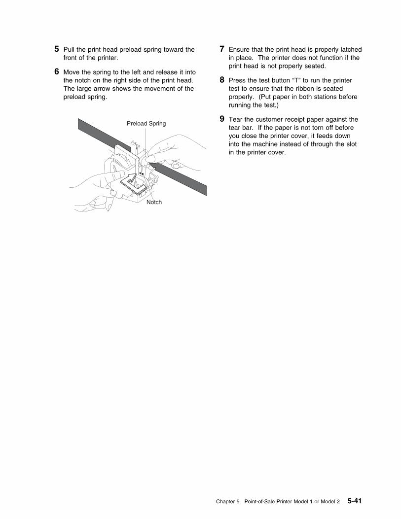
5 Pull the print head preload spring toward thefront of the printer.
6 Move the spring to the left and release it intothe notch on the right side of the print head.The large arrow shows the movement of thepreload spring.
Preload Spring
Notch
7 Ensure that the print head is properly latchedin place. The printer does not function if theprint head is not properly seated.
8 Press the test button “T” to run the printertest to ensure that the ribbon is seatedproperly. (Put paper in both stations beforerunning the test.)
9 Tear the customer receipt paper against thetear bar. If the paper is not torn off beforeyou close the printer cover, it feeds downinto the machine instead of through the slotin the printer cover.
Chapter 5. Point-of-Sale Printer Model 1 or Model 2 5-41
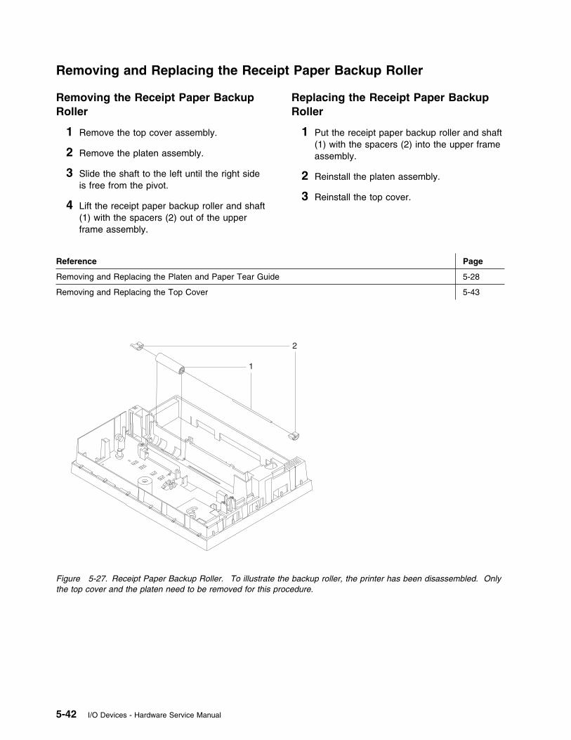
Removing and Replacing the Receipt Paper Backup Roller
Removing the Receipt Paper BackupRoller
1 Remove the top cover assembly.
2 Remove the platen assembly.
3 Slide the shaft to the left until the right sideis free from the pivot.
4 Lift the receipt paper backup roller and shaft(1) with the spacers (2) out of the upperframe assembly.
Replacing the Receipt Paper BackupRoller
1 Put the receipt paper backup roller and shaft(1) with the spacers (2) into the upper frameassembly.
2 Reinstall the platen assembly.
3 Reinstall the top cover.
Reference Page
Removing and Replacing the Platen and Paper Tear Guide 5-28
Removing and Replacing the Top Cover 5-43
1
2
Figure 5-27. Receipt Paper Backup Roller. To illustrate the backup roller, the printer has been disassembled. Onlythe top cover and the platen need to be removed for this procedure.
5-42 I/O Devices - Hardware Service Manual
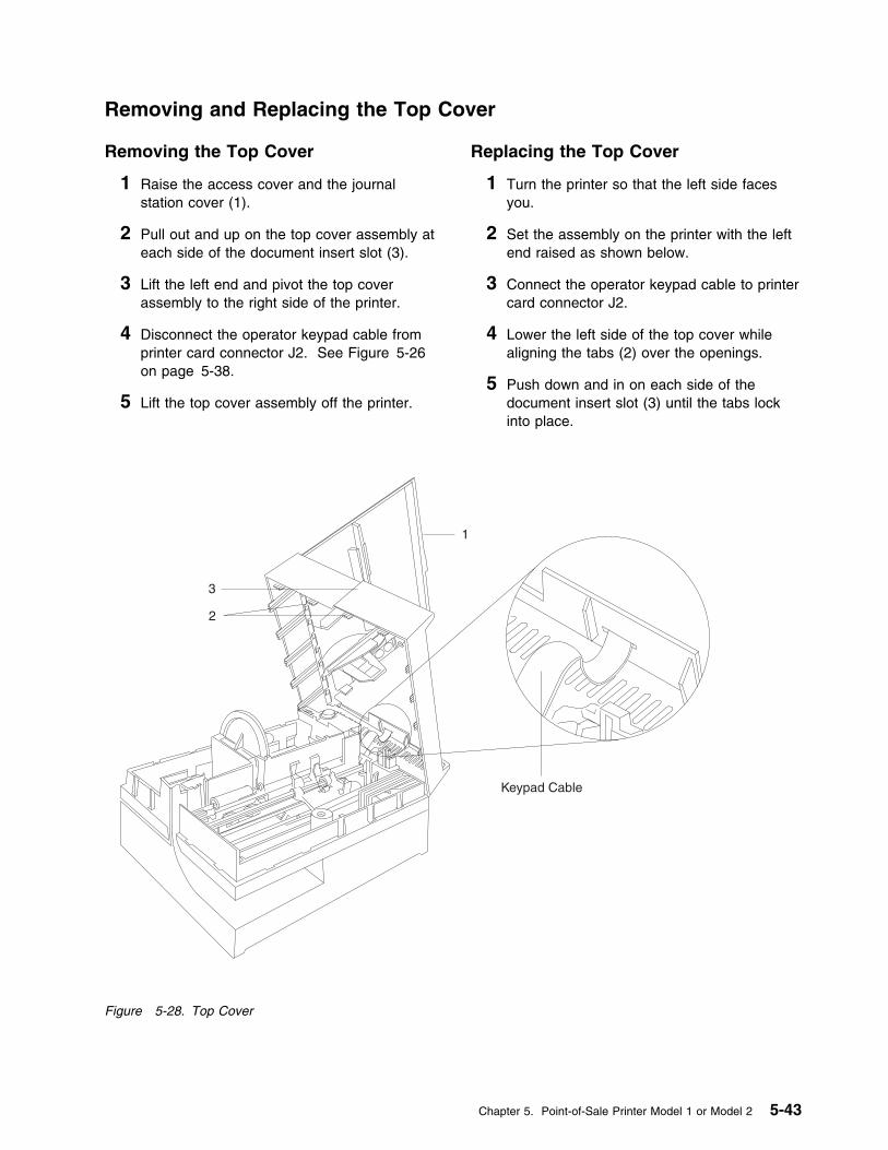
Removing and Replacing the Top Cover
Removing the Top Cover
1 Raise the access cover and the journalstation cover (1).
2 Pull out and up on the top cover assembly ateach side of the document insert slot (3).
3 Lift the left end and pivot the top coverassembly to the right side of the printer.
4 Disconnect the operator keypad cable fromprinter card connector J2. See Figure 5-26on page 5-38.
5 Lift the top cover assembly off the printer.
Replacing the Top Cover
1 Turn the printer so that the left side facesyou.
2 Set the assembly on the printer with the leftend raised as shown below.
3 Connect the operator keypad cable to printercard connector J2.
4 Lower the left side of the top cover whilealigning the tabs (2) over the openings.
5 Push down and in on each side of thedocument insert slot (3) until the tabs lockinto place.
1
2
3
Keypad Cable
Figure 5-28. Top Cover
Chapter 5. Point-of-Sale Printer Model 1 or Model 2 5-43
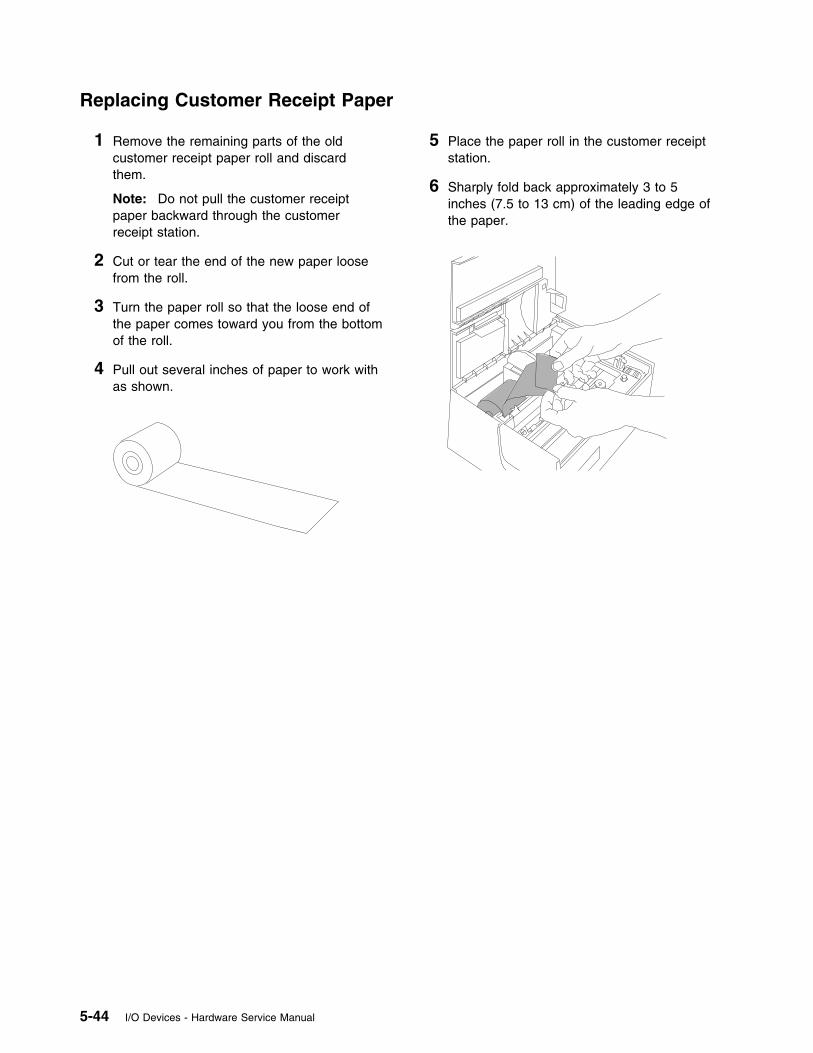
Replacing Customer Receipt Paper
1 Remove the remaining parts of the oldcustomer receipt paper roll and discardthem.
Note: Do not pull the customer receiptpaper backward through the customerreceipt station.
2 Cut or tear the end of the new paper loosefrom the roll.
3 Turn the paper roll so that the loose end ofthe paper comes toward you from the bottomof the roll.
4 Pull out several inches of paper to work withas shown.
5 Place the paper roll in the customer receiptstation.
6 Sharply fold back approximately 3 to 5inches (7.5 to 13 cm) of the leading edge ofthe paper.
5-44 I/O Devices - Hardware Service Manual
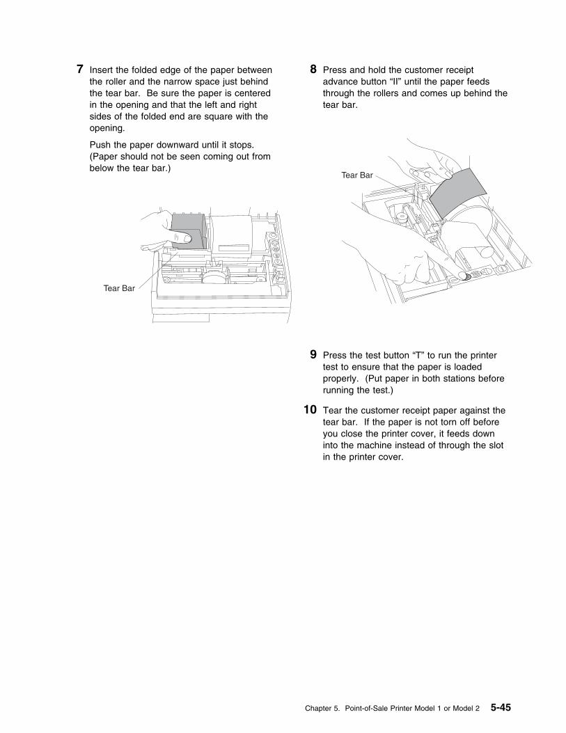
7 Insert the folded edge of the paper betweenthe roller and the narrow space just behindthe tear bar. Be sure the paper is centeredin the opening and that the left and rightsides of the folded end are square with theopening.
Push the paper downward until it stops.(Paper should not be seen coming out frombelow the tear bar.)
Tear Bar
8 Press and hold the customer receiptadvance button “II” until the paper feedsthrough the rollers and comes up behind thetear bar.
Tear Bar
9 Press the test button “T” to run the printertest to ensure that the paper is loadedproperly. (Put paper in both stations beforerunning the test.)
10 Tear the customer receipt paper against thetear bar. If the paper is not torn off beforeyou close the printer cover, it feeds downinto the machine instead of through the slotin the printer cover.
Chapter 5. Point-of-Sale Printer Model 1 or Model 2 5-45
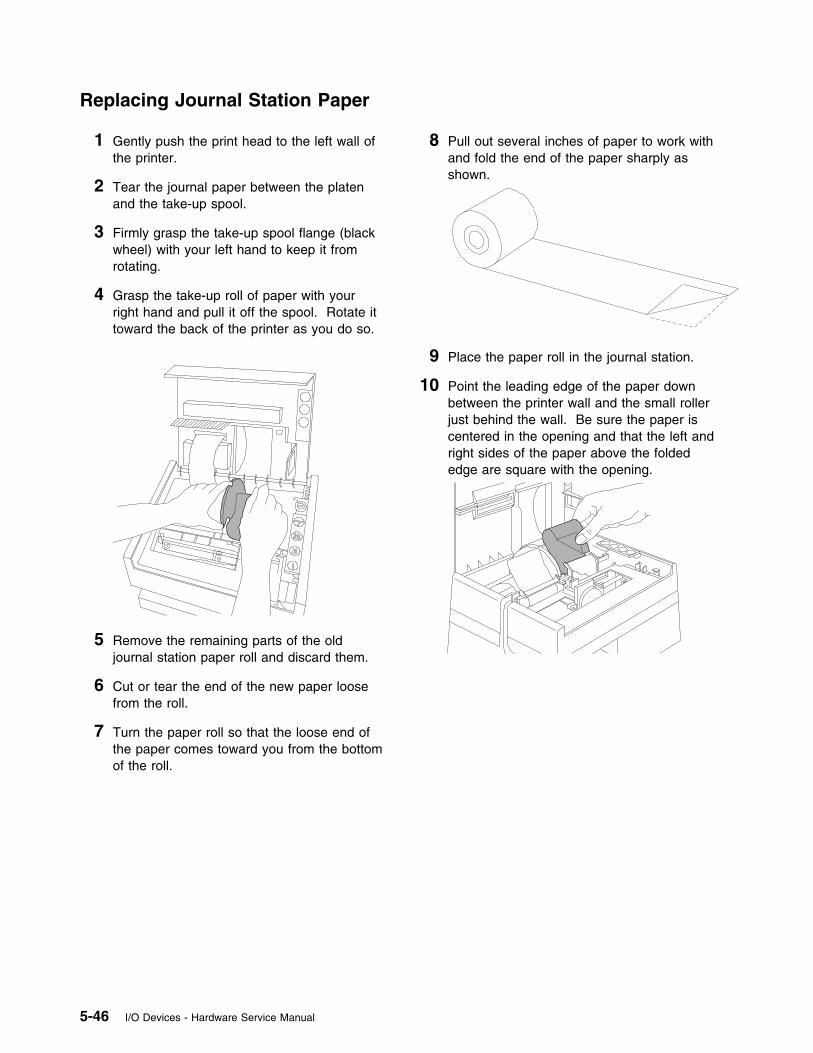
Replacing Journal Station Paper
1 Gently push the print head to the left wall ofthe printer.
2 Tear the journal paper between the platenand the take-up spool.
3 Firmly grasp the take-up spool flange (blackwheel) with your left hand to keep it fromrotating.
4 Grasp the take-up roll of paper with yourright hand and pull it off the spool. Rotate ittoward the back of the printer as you do so.
5 Remove the remaining parts of the oldjournal station paper roll and discard them.
6 Cut or tear the end of the new paper loosefrom the roll.
7 Turn the paper roll so that the loose end ofthe paper comes toward you from the bottomof the roll.
8 Pull out several inches of paper to work withand fold the end of the paper sharply asshown.
9 Place the paper roll in the journal station.
10 Point the leading edge of the paper downbetween the printer wall and the small rollerjust behind the wall. Be sure the paper iscentered in the opening and that the left andright sides of the paper above the foldededge are square with the opening.
5-46 I/O Devices - Hardware Service Manual

11 Put your fingers behind the paper and holdthe paper against the back of the wall.
12 Use your fingers to repeatedly slide thepaper down until it loops underneath andreappears in front.
13 Pull the paper straight up and toward you,about 8 inches.
14 Sharply fold back the leading edge of thepaper approximately 1 to 2 inches as shown.
15 Pull the paper over the top of the take-upspool.
16 Turn the paper fold down and slip the foldededge of the paper under the retainer (shownin the dotted lines) on the take-up spool.
Turn the take-up spool toward the back ofthe printer to take the slack out of the paper.Gently push the paper toward the left side ofthe printer to keep the edge even as it loopsaround the take-up spool.
17 When the paper is wound snugly around thespool, press and hold the journal paperadvance button “III” for a few seconds.
18 Press the test button “T” to run the printertest to ensure that the paper is loadedproperly. (Put paper in both stations beforerunning the test.)
19 Tear the customer receipt paper against thetear bar. If the paper is not torn off beforeyou close the printer cover, it feeds downinto the machine instead of through the slotin the printer cover.
Chapter 5. Point-of-Sale Printer Model 1 or Model 2 5-47
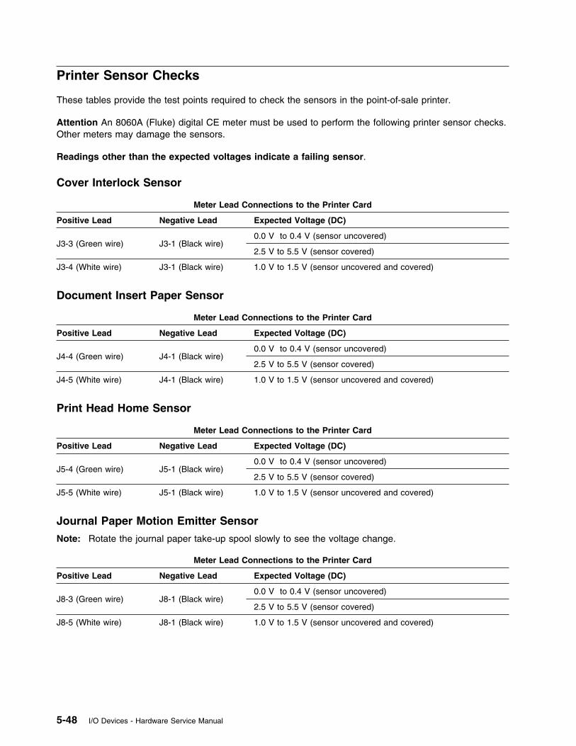
Printer Sensor Checks
These tables provide the test points required to check the sensors in the point-of-sale printer.
Attention An 8060A (Fluke) digital CE meter must be used to perform the following printer sensor checks.Other meters may damage the sensors.
Readings other than the expected voltages indicate a failing sensor.
Cover Interlock Sensor
Meter Lead Connections to the Printer Card
Positive Lead Negative Lead Expected Voltage (DC)
J3-3 (Green wire) J3-1 (Black wire)0.0 V to 0.4 V (sensor uncovered)
2.5 V to 5.5 V (sensor covered)
J3-4 (White wire) J3-1 (Black wire) 1.0 V to 1.5 V (sensor uncovered and covered)
Document Insert Paper Sensor
Meter Lead Connections to the Printer Card
Positive Lead Negative Lead Expected Voltage (DC)
J4-4 (Green wire) J4-1 (Black wire)0.0 V to 0.4 V (sensor uncovered)
2.5 V to 5.5 V (sensor covered)
J4-5 (White wire) J4-1 (Black wire) 1.0 V to 1.5 V (sensor uncovered and covered)
Print Head Home Sensor
Meter Lead Connections to the Printer Card
Positive Lead Negative Lead Expected Voltage (DC)
J5-4 (Green wire) J5-1 (Black wire)0.0 V to 0.4 V (sensor uncovered)
2.5 V to 5.5 V (sensor covered)
J5-5 (White wire) J5-1 (Black wire) 1.0 V to 1.5 V (sensor uncovered and covered)
Journal Paper Motion Emitter Sensor
Note: Rotate the journal paper take-up spool slowly to see the voltage change.
Meter Lead Connections to the Printer Card
Positive Lead Negative Lead Expected Voltage (DC)
J8-3 (Green wire) J8-1 (Black wire)0.0 V to 0.4 V (sensor uncovered)
2.5 V to 5.5 V (sensor covered)
J8-5 (White wire) J8-1 (Black wire) 1.0 V to 1.5 V (sensor uncovered and covered)
5-48 I/O Devices - Hardware Service Manual
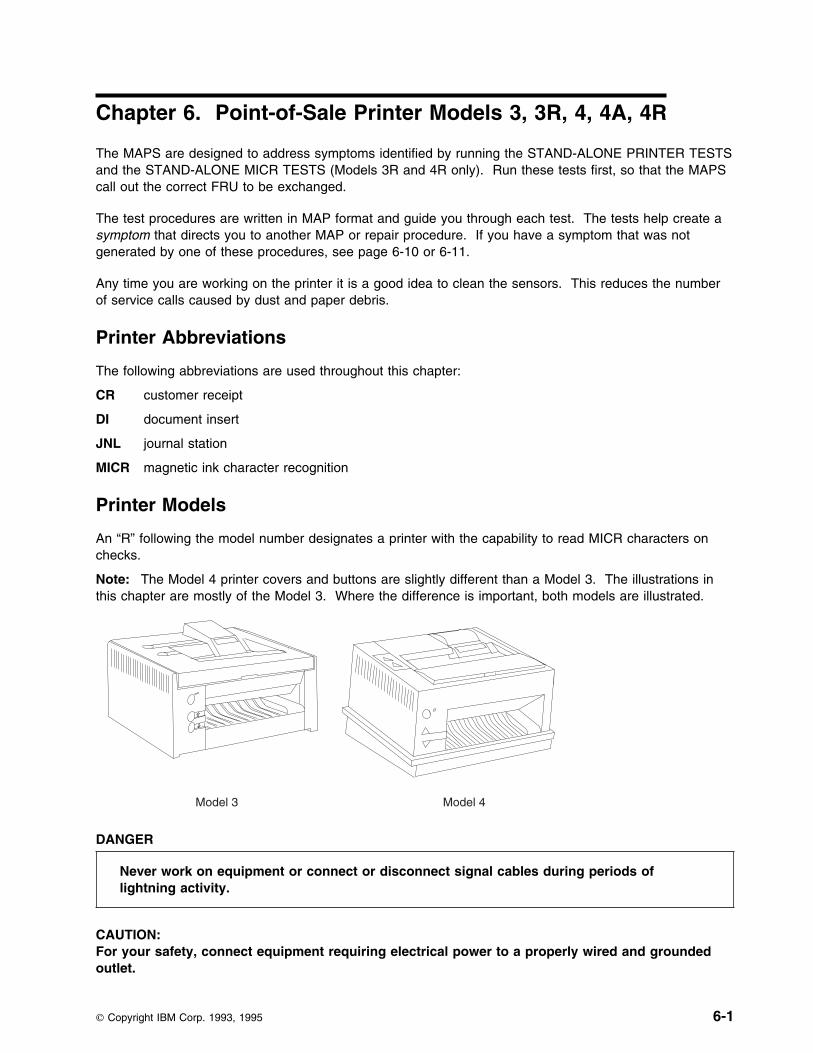
Chapter 6. Point-of-Sale Printer Models 3, 3R, 4, 4A, 4R
The MAPS are designed to address symptoms identified by running the STAND-ALONE PRINTER TESTSand the STAND-ALONE MICR TESTS (Models 3R and 4R only). Run these tests first, so that the MAPScall out the correct FRU to be exchanged.
The test procedures are written in MAP format and guide you through each test. The tests help create asymptom that directs you to another MAP or repair procedure. If you have a symptom that was notgenerated by one of these procedures, see page 6-10 or 6-11.
Any time you are working on the printer it is a good idea to clean the sensors. This reduces the numberof service calls caused by dust and paper debris.
Printer Abbreviations
The following abbreviations are used throughout this chapter:
CR customer receipt
DI document insert
JNL journal station
MICR magnetic ink character recognition
Printer Models
An “R” following the model number designates a printer with the capability to read MICR characters onchecks.
Note: The Model 4 printer covers and buttons are slightly different than a Model 3. The illustrations inthis chapter are mostly of the Model 3. Where the difference is important, both models are illustrated.
Model 3 Model 4
DANGER
Never work on equipment or connect or disconnect signal cables during periods oflightning activity.
CAUTION:For your safety, connect equipment requiring electrical power to a properly wired and groundedoutlet.
Copyright IBM Corp. 1993, 1995 6-1

Electrostatic Discharge (ESD)
Attention ESD damage can occur when there is a difference in charge between the part, the product, andthe service person. No damage will occur if the service person and the part being installed are at thesame charge level.
ESD Damage Prevention – Anytime a service action involves physical contact with logic cards, modules,back-panel pins, or other ESD sensitive (ESDS) parts, the service person must be connected to an ESDcommon ground point on the product through the ESD wrist strap and cord. The ESD ground clip can beattached to any frame ground, ground braid, green wire ground, or the round ground prong on the ACpower plug. Coax or connector outside shells can also be used.
Handling Removed Cards – Logic cards removed from a product should be placed in ESD protectivecontainers. No other object should be allowed inside the ESD container with the logic card. Attach tagsor reports that must accompany the card to the outside of the container.
6-2 I/O Devices - Hardware Service Manual
TEST 4100: Stand-Alone Printer Test . . . . . . . . . . . . . . . . . . . . . . . . . . . . . . . . . . . . 6-4Stand-Alone MICR Test . . . . . . . . . . . . . . . . . . . . . . . . . . . . . . . . . . . . . . . . . . . . . 6-8
Special MICR Characters . . . . . . . . . . . . . . . . . . . . . . . . . . . . . . . . . . . . . . . . . . 6-9MICR Head and Feed Rollers Cleaning Procedure . . . . . . . . . . . . . . . . . . . . . . . . . . . . 6-9
Printer Messages . . . . . . . . . . . . . . . . . . . . . . . . . . . . . . . . . . . . . . . . . . . . . . . . 6-10Printer Symptoms . . . . . . . . . . . . . . . . . . . . . . . . . . . . . . . . . . . . . . . . . . . . . . . 6-11MAP 4110: CR or JNL Paper Advances Continuously . . . . . . . . . . . . . . . . . . . . . . . . . . 6-13MAP 4120: Paper Cutter Does Not Cut Properly . . . . . . . . . . . . . . . . . . . . . . . . . . . . . 6-14MAP 4130: CR Paper Does Not Advance . . . . . . . . . . . . . . . . . . . . . . . . . . . . . . . . . 6-16MAP 4140: CR Paper Jams . . . . . . . . . . . . . . . . . . . . . . . . . . . . . . . . . . . . . . . . . 6-19MAP 4150: CR Station is Overprinting . . . . . . . . . . . . . . . . . . . . . . . . . . . . . . . . . . . 6-21MAP 4160: DI Paper Advances Continuously . . . . . . . . . . . . . . . . . . . . . . . . . . . . . . . 6-22MAP 4170: DI Station Does Not Feed Documents Correctly or Is Overprinting . . . . . . . . . . . . 6-23MAP 4180: Home Errors . . . . . . . . . . . . . . . . . . . . . . . . . . . . . . . . . . . . . . . . . . . 6-27MAP 4190: JNL Paper Does Not Advance . . . . . . . . . . . . . . . . . . . . . . . . . . . . . . . . . 6-29MAP 4200: JNL Station Not Printing . . . . . . . . . . . . . . . . . . . . . . . . . . . . . . . . . . . . 6-32MAP 4210: JNL Station is Overprinting . . . . . . . . . . . . . . . . . . . . . . . . . . . . . . . . . . . 6-35MAP 4220: MICR Does Not Read Correctly . . . . . . . . . . . . . . . . . . . . . . . . . . . . . . . . 6-36MAP 4230: Power Problems . . . . . . . . . . . . . . . . . . . . . . . . . . . . . . . . . . . . . . . . . 6-39MAP 4240: Printed Characters are Light . . . . . . . . . . . . . . . . . . . . . . . . . . . . . . . . . . 6-43MAP 4250: Printed Characters Missing One or More Dot Rows . . . . . . . . . . . . . . . . . . . . 6-45MAP 4260: Printed Characters Are Smudged . . . . . . . . . . . . . . . . . . . . . . . . . . . . . . . 6-47MAP 4270: Printer Indicator Light Always On or Comes On Randomly . . . . . . . . . . . . . . . . 6-48MAP 4280: Printer Indicator Light Not On . . . . . . . . . . . . . . . . . . . . . . . . . . . . . . . . . 6-49MAP 4290: Printer Indicator Light Not On When A Document Is Inserted . . . . . . . . . . . . . . . 6-51MAP 4300: Printer Not Printing Any Characters . . . . . . . . . . . . . . . . . . . . . . . . . . . . . . 6-53MAP 4310: Ribbon Damaged by Printer . . . . . . . . . . . . . . . . . . . . . . . . . . . . . . . . . . 6-55MAP 4320: Ribbon Does Not Advance . . . . . . . . . . . . . . . . . . . . . . . . . . . . . . . . . . . 6-56MAP 4330: CR Motor Resistance Checks . . . . . . . . . . . . . . . . . . . . . . . . . . . . . . . . . 6-57MAP 4340: Paper Cutter Motor Resistance Checks . . . . . . . . . . . . . . . . . . . . . . . . . . . 6-58MAP 4350: DI Motor Resistance Checks . . . . . . . . . . . . . . . . . . . . . . . . . . . . . . . . . . 6-59MAP 4360: JNL Motor Resistance Checks . . . . . . . . . . . . . . . . . . . . . . . . . . . . . . . . . 6-60MAP 4370: Print Head Resistance Checks . . . . . . . . . . . . . . . . . . . . . . . . . . . . . . . . 6-61MAP 4380: Transport Motor Resistance Checks . . . . . . . . . . . . . . . . . . . . . . . . . . . . . 6-62Printer Sensor Checks . . . . . . . . . . . . . . . . . . . . . . . . . . . . . . . . . . . . . . . . . . . . . 6-63
Sensor Cleaning Procedures . . . . . . . . . . . . . . . . . . . . . . . . . . . . . . . . . . . . . . . 6-66DI Sensors . . . . . . . . . . . . . . . . . . . . . . . . . . . . . . . . . . . . . . . . . . . . . . . . 6-66Home Sensor Card . . . . . . . . . . . . . . . . . . . . . . . . . . . . . . . . . . . . . . . . . . . 6-66JNL Paper Sensor . . . . . . . . . . . . . . . . . . . . . . . . . . . . . . . . . . . . . . . . . . . . 6-66
Printer Adjustments . . . . . . . . . . . . . . . . . . . . . . . . . . . . . . . . . . . . . . . . . . . . . . 6-67Using the 4680/4690 Operating System . . . . . . . . . . . . . . . . . . . . . . . . . . . . . . . . . 6-67Using the Reference Diskette . . . . . . . . . . . . . . . . . . . . . . . . . . . . . . . . . . . . . . . 6-67
Printer Cards . . . . . . . . . . . . . . . . . . . . . . . . . . . . . . . . . . . . . . . . . . . . . . . 6-69Removal and Replacement Procedures . . . . . . . . . . . . . . . . . . . . . . . . . . . . . . . . . . . 6-70
Chapter 6. Point-of-Sale Printer Models 3, 3R, 4, 4A, 4R 6-3
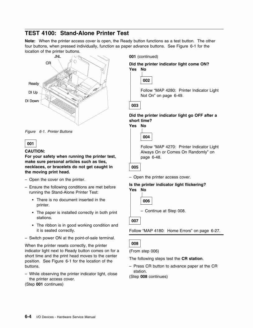
TEST 4100: Stand-Alone Printer TestNote: When the printer access cover is open, the Ready button functions as a test button. The otherfour buttons, when pressed individually, function as paper advance buttons. See Figure 6-1 for thelocation of the printer buttons.
Figure 6-1. Printer Buttons
001
CAUTION:For your safety when running the printer test,make sure personal articles such as ties,necklaces, or bracelets do not get caught inthe moving print head.
– Open the cover on the printer.
– Ensure the following conditions are met beforerunning the Stand-Alone Printer Test:
� There is no document inserted in theprinter.
� The paper is installed correctly in both printstations.
� The ribbon is in good working condition andit is seated correctly.
– Switch power ON at the point-of-sale terminal.
When the printer resets correctly, the printerindicator light next to Ready button comes on for ashort time and the print head moves to the centerposition. See Figure 6-1 for the location of thebuttons.
– While observing the printer indicator light, closethe printer access cover.
(Step 001 continues)
001 (continued)
Did the printer indicator light come ON?Yes No
002
Follow “MAP 4280: Printer Indicator LightNot On” on page 6-49.
003
Did the printer indicator light go OFF after ashort time?Yes No
004
Follow “MAP 4270: Printer Indicator LightAlways On or Comes On Randomly” onpage 6-48.
005
– Open the printer access cover.
Is the printer indicator light flickering?Yes No
006
– Continue at Step 008.
007
Follow “MAP 4180: Home Errors” on page 6-27.
008
(From step 006)
The following steps test the CR station.
– Press CR button to advance paper at the CRstation.
(Step 008 continues)
6-4 I/O Devices - Hardware Service Manual
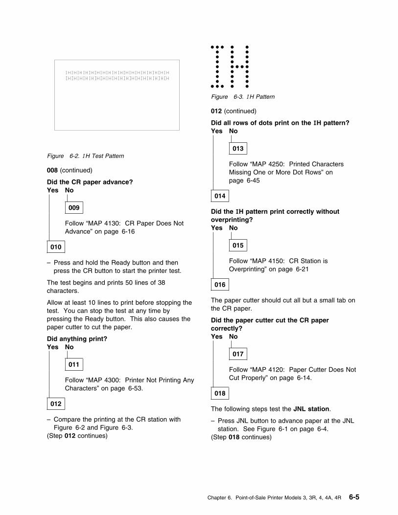
Figure 6-2. IH Test Pattern
Figure 6-3. IH Pattern
012 (continued)
Did all rows of dots print on the IH pattern?Yes No
013
Follow “MAP 4250: Printed CharactersMissing One or More Dot Rows” onpage 6-45
014
Did the IH pattern print correctly withoutoverprinting?Yes No
015
Follow “MAP 4150: CR Station isOverprinting” on page 6-21
016
The paper cutter should cut all but a small tab onthe CR paper.
Did the paper cutter cut the CR papercorrectly?Yes No
017
Follow “MAP 4120: Paper Cutter Does NotCut Properly” on page 6-14.
018
The following steps test the JNL station.
– Press JNL button to advance paper at the JNLstation. See Figure 6-1 on page 6-4.
(Step 018 continues)
008 (continued)
Did the CR paper advance?Yes No
009
Follow “MAP 4130: CR Paper Does NotAdvance” on page 6-16
010
– Press and hold the Ready button and thenpress the CR button to start the printer test.
The test begins and prints 50 lines of 38characters.
Allow at least 10 lines to print before stopping thetest. You can stop the test at any time bypressing the Ready button. This also causes thepaper cutter to cut the paper.
Did anything print?Yes No
011
Follow “MAP 4300: Printer Not Printing AnyCharacters” on page 6-53.
012
– Compare the printing at the CR station withFigure 6-2 and Figure 6-3.
(Step 012 continues)
Chapter 6. Point-of-Sale Printer Models 3, 3R, 4, 4A, 4R 6-5
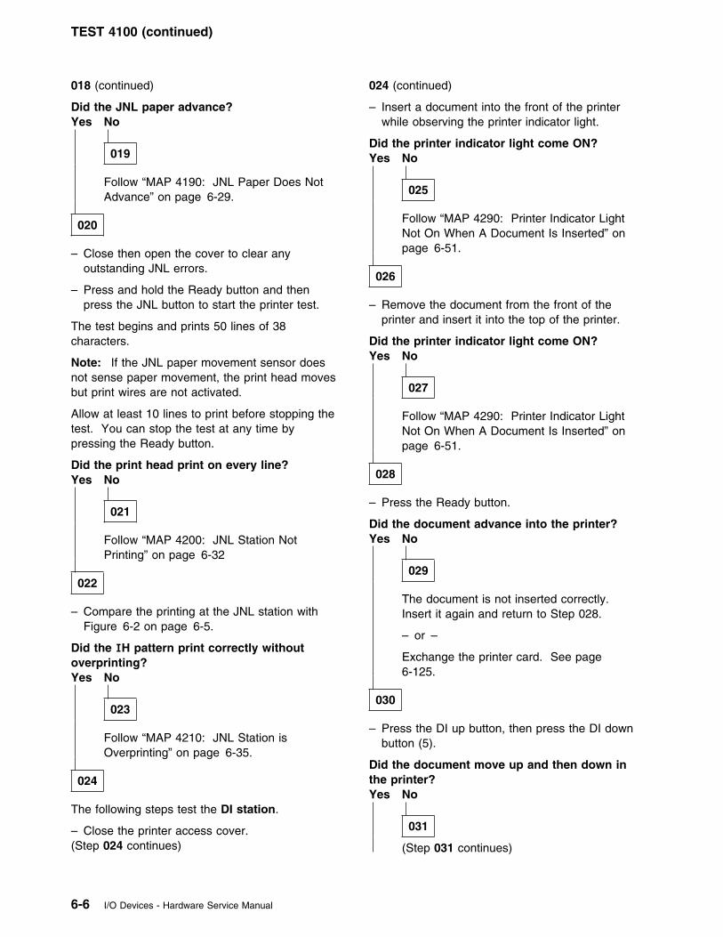
TEST 4100 (continued)
018 (continued)
Did the JNL paper advance?Yes No
019
Follow “MAP 4190: JNL Paper Does NotAdvance” on page 6-29.
020
– Close then open the cover to clear anyoutstanding JNL errors.
– Press and hold the Ready button and thenpress the JNL button to start the printer test.
The test begins and prints 50 lines of 38characters.
Note: If the JNL paper movement sensor doesnot sense paper movement, the print head movesbut print wires are not activated.
Allow at least 10 lines to print before stopping thetest. You can stop the test at any time bypressing the Ready button.
Did the print head print on every line?Yes No
021
Follow “MAP 4200: JNL Station NotPrinting” on page 6-32
022
– Compare the printing at the JNL station withFigure 6-2 on page 6-5.
Did the IH pattern print correctly withoutoverprinting?Yes No
023
Follow “MAP 4210: JNL Station isOverprinting” on page 6-35.
024
The following steps test the DI station.
– Close the printer access cover.(Step 024 continues)
024 (continued)
– Insert a document into the front of the printerwhile observing the printer indicator light.
Did the printer indicator light come ON?Yes No
025
Follow “MAP 4290: Printer Indicator LightNot On When A Document Is Inserted” onpage 6-51.
026
– Remove the document from the front of theprinter and insert it into the top of the printer.
Did the printer indicator light come ON?Yes No
027
Follow “MAP 4290: Printer Indicator LightNot On When A Document Is Inserted” onpage 6-51.
028
– Press the Ready button.
Did the document advance into the printer?Yes No
029
The document is not inserted correctly.Insert it again and return to Step 028.
– or –
Exchange the printer card. See page6-125.
030
– Press the DI up button, then press the DI downbutton (5).
Did the document move up and then down inthe printer?Yes No
031
(Step 031 continues)
6-6 I/O Devices - Hardware Service Manual
031 (continued)
Follow “MAP 4170: DI Station Does NotFeed Documents Correctly or IsOverprinting” on page 6-23.
032
– Open the printer access cover.
– Press and hold the Ready button and thenpress the DI down button (5) to start the printertest.
The test begins and prints lines of 38 charactersfor 50 lines or until the end of the document isreached.
Allow a few lines to print before stopping the test.
You can stop the test at any time by pressing theReady button.
Did the printer print without overprinting?Yes No
033
See page 6-23.
034
The Stand-Alone Printer Test is complete. If youare working on a Model 3R or 4R printer, go to“Stand-Alone MICR Test” on page 6-8 andperform the MICR test.
Chapter 6. Point-of-Sale Printer Models 3, 3R, 4, 4A, 4R 6-7
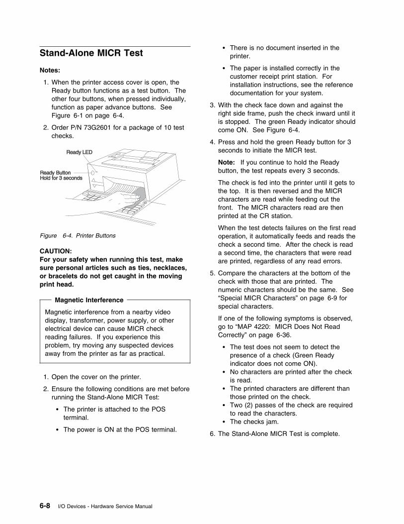
Stand-Alone MICR Test
Notes:
1. When the printer access cover is open, theReady button functions as a test button. Theother four buttons, when pressed individually,function as paper advance buttons. SeeFigure 6-1 on page 6-4.
2. Order P/N 73G2601 for a package of 10 testchecks.
Figure 6-4. Printer Buttons
CAUTION:For your safety when running this test, makesure personal articles such as ties, necklaces,or bracelets do not get caught in the movingprint head.
Magnetic Interference
Magnetic interference from a nearby videodisplay, transformer, power supply, or otherelectrical device can cause MICR checkreading failures. If you experience thisproblem, try moving any suspected devicesaway from the printer as far as practical.
1. Open the cover on the printer.
2. Ensure the following conditions are met beforerunning the Stand-Alone MICR Test:
� The printer is attached to the POSterminal.
� The power is ON at the POS terminal.
� There is no document inserted in theprinter.
� The paper is installed correctly in thecustomer receipt print station. Forinstallation instructions, see the referencedocumentation for your system.
3. With the check face down and against theright side frame, push the check inward until itis stopped. The green Ready indicator shouldcome ON. See Figure 6-4.
4. Press and hold the green Ready button for 3seconds to initiate the MICR test.
Note: If you continue to hold the Readybutton, the test repeats every 3 seconds.
The check is fed into the printer until it gets tothe top. It is then reversed and the MICRcharacters are read while feeding out thefront. The MICR characters read are thenprinted at the CR station.
When the test detects failures on the first readoperation, it automatically feeds and reads thecheck a second time. After the check is reada second time, the characters that were readare printed, regardless of any read errors.
5. Compare the characters at the bottom of thecheck with those that are printed. Thenumeric characters should be the same. See“Special MICR Characters” on page 6-9 forspecial characters.
If one of the following symptoms is observed,go to “MAP 4220: MICR Does Not ReadCorrectly” on page 6-36.
� The test does not seem to detect thepresence of a check (Green Readyindicator does not come ON).
� No characters are printed after the checkis read.
� The printed characters are different thanthose printed on the check.
� Two (2) passes of the check are requiredto read the characters.
� The checks jam.
6. The Stand-Alone MICR Test is complete.
6-8 I/O Devices - Hardware Service Manual
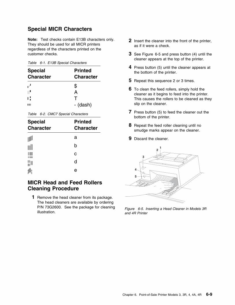
Special MICR Characters
Note: Test checks contain E13B characters only.They should be used for all MICR printersregardless of the characters printed on thecustomer checks.
MICR Head and Feed RollersCleaning Procedure
1 Remove the head cleaner from its package.The head cleaners are available by orderingP/N 73G2600. See the package for cleaningillustration.
2 Insert the cleaner into the front of the printer,as if it were a check.
3 See Figure 6-5 and press button (4) until thecleaner appears at the top of the printer.
4 Press button (5) until the cleaner appears atthe bottom of the printer.
5 Repeat this sequence 2 or 3 times.
6 To clean the feed rollers, simply hold thecleaner as it begins to feed into the printer.This causes the rollers to be cleaned as theyslip on the cleaner.
7 Press button (5) to feed the cleaner out thebottom of the printer.
8 Repeat the feed roller cleaning until nosmudge marks appear on the cleaner.
9 Discard the cleaner.
Figure 6-5. Inserting a Head Cleaner in Models 3Rand 4R Printer
Table 6-1. E13B Special Characters
SpecialCharacter
PrintedCharacter
$AT- (dash)
Table 6-2. CMC7 Special Characters
SpecialCharacter
PrintedCharacter
a
b
c
d
e
Chapter 6. Point-of-Sale Printer Models 3, 3R, 4, 4A, 4R 6-9

Printer Messages
Table 6-3. Printer Messages
Printer Message Repair Actions
6334633863B463B8
Perform further testing using system online tests or reference diskette diagnostics.
T7151 � Exchange the printer card. See page 6-125.
� Exchange cable 7.
T7152 Follow “MAP 4180: Home Errors” on page 6-27.
T7153T7154T7155T7156T7157
If the Stand-Alone Printer Tests run OK, exchange the printer card. See page 6-125.
T7159 Exchange the printer card. See page 6-125.
T7167T7168
If Stand-Alone Printer Tests run OK, exchange the printer card. See page 6-125.
W304W305W354W355
Perform further testing using system online tests or reference diskette diagnostics.
6-10 I/O Devices - Hardware Service Manual
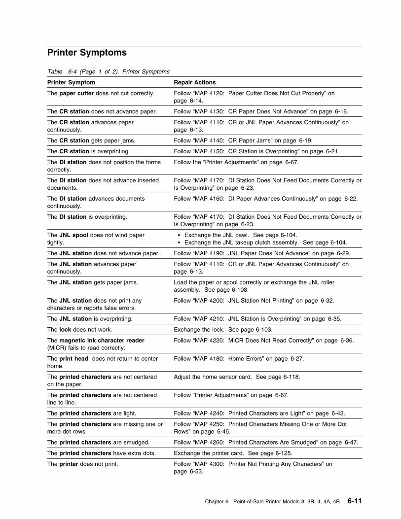
Printer Symptoms
Table 6-4 (Page 1 of 2). Printer Symptoms
Printer Symptom Repair Actions
The paper cutter does not cut correctly. Follow “MAP 4120: Paper Cutter Does Not Cut Properly” onpage 6-14.
The CR station does not advance paper. Follow “MAP 4130: CR Paper Does Not Advance” on page 6-16.
The CR station advances papercontinuously.
Follow “MAP 4110: CR or JNL Paper Advances Continuously” onpage 6-13.
The CR station gets paper jams. Follow “MAP 4140: CR Paper Jams” on page 6-19.
The CR station is overprinting. Follow “MAP 4150: CR Station is Overprinting” on page 6-21.
The DI station does not position the formscorrectly.
Follow the “Printer Adjustments” on page 6-67.
The DI station does not advance inserteddocuments.
Follow “MAP 4170: DI Station Does Not Feed Documents Correctly orIs Overprinting” on page 6-23.
The DI station advances documentscontinuously.
Follow “MAP 4160: DI Paper Advances Continuously” on page 6-22.
The DI station is overprinting. Follow “MAP 4170: DI Station Does Not Feed Documents Correctly orIs Overprinting” on page 6-23.
The JNL spool does not wind papertightly.
� Exchange the JNL pawl. See page 6-104.� Exchange the JNL takeup clutch assembly. See page 6-104.
The JNL station does not advance paper. Follow “MAP 4190: JNL Paper Does Not Advance” on page 6-29.
The JNL station advances papercontinuously.
Follow “MAP 4110: CR or JNL Paper Advances Continuously” onpage 6-13.
The JNL station gets paper jams. Load the paper or spool correctly or exchange the JNL rollerassembly. See page 6-108.
The JNL station does not print anycharacters or reports false errors.
Follow “MAP 4200: JNL Station Not Printing” on page 6-32.
The JNL station is overprinting. Follow “MAP 4210: JNL Station is Overprinting” on page 6-35.
The lock does not work. Exchange the lock. See page 6-103.
The magnetic ink character reader(MICR) fails to read correctly.
Follow “MAP 4220: MICR Does Not Read Correctly” on page 6-36.
The print head does not return to centerhome.
Follow “MAP 4180: Home Errors” on page 6-27.
The printed characters are not centeredon the paper.
Adjust the home sensor card. See page 6-118.
The printed characters are not centeredline to line.
Follow “Printer Adjustments” on page 6-67.
The printed characters are light. Follow “MAP 4240: Printed Characters are Light” on page 6-43.
The printed characters are missing one ormore dot rows.
Follow “MAP 4250: Printed Characters Missing One or More DotRows” on page 6-45.
The printed characters are smudged. Follow “MAP 4260: Printed Characters Are Smudged” on page 6-47.
The printed characters have extra dots. Exchange the printer card. See page 6-125.
The printer does not print. Follow “MAP 4300: Printer Not Printing Any Characters” onpage 6-53.
Chapter 6. Point-of-Sale Printer Models 3, 3R, 4, 4A, 4R 6-11
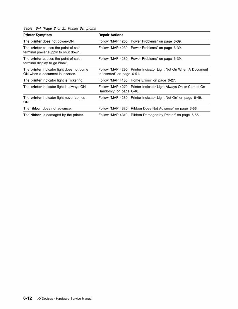
Table 6-4 (Page 2 of 2). Printer Symptoms
Printer Symptom Repair Actions
The printer does not power-ON. Follow “MAP 4230: Power Problems” on page 6-39.
The printer causes the point-of-saleterminal power supply to shut down.
Follow “MAP 4230: Power Problems” on page 6-39.
The printer causes the point-of-saleterminal display to go blank.
Follow “MAP 4230: Power Problems” on page 6-39.
The printer indicator light does not comeON when a document is inserted.
Follow “MAP 4290: Printer Indicator Light Not On When A DocumentIs Inserted” on page 6-51.
The printer indicator light is flickering. Follow “MAP 4180: Home Errors” on page 6-27.
The printer indicator light is always ON. Follow “MAP 4270: Printer Indicator Light Always On or Comes OnRandomly” on page 6-48.
The printer indicator light never comesON.
Follow “MAP 4280: Printer Indicator Light Not On” on page 6-49.
The ribbon does not advance. Follow “MAP 4320: Ribbon Does Not Advance” on page 6-56.
The ribbon is damaged by the printer. Follow “MAP 4310: Ribbon Damaged by Printer” on page 6-55.
6-12 I/O Devices - Hardware Service Manual
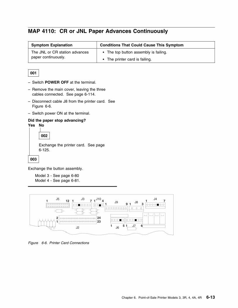
MAP 4110: CR or JNL Paper Advances Continuously
Symptom Explanation Conditions That Could Cause This Symptom
The JNL or CR station advancespaper continuously.
� The top button assembly is failing.
� The printer card is failing.
001
– Switch POWER OFF at the terminal.
– Remove the main cover, leaving the threecables connected. See page 6-114.
– Disconnect cable J8 from the printer card. SeeFigure 6-6.
– Switch power ON at the terminal.
Did the paper stop advancing?Yes No
002
Exchange the printer card. See page6-125.
003
Exchange the button assembly.
Model 3 - See page 6-80 Model 4 - See page 6-81.
1J5
12 1J3
7
21
2423
J10
1J9 9 1
1 5 1J6
J7 6
31
J47J81 4
J2
Figure 6-6. Printer Card Connections
Chapter 6. Point-of-Sale Printer Models 3, 3R, 4, 4A, 4R 6-13
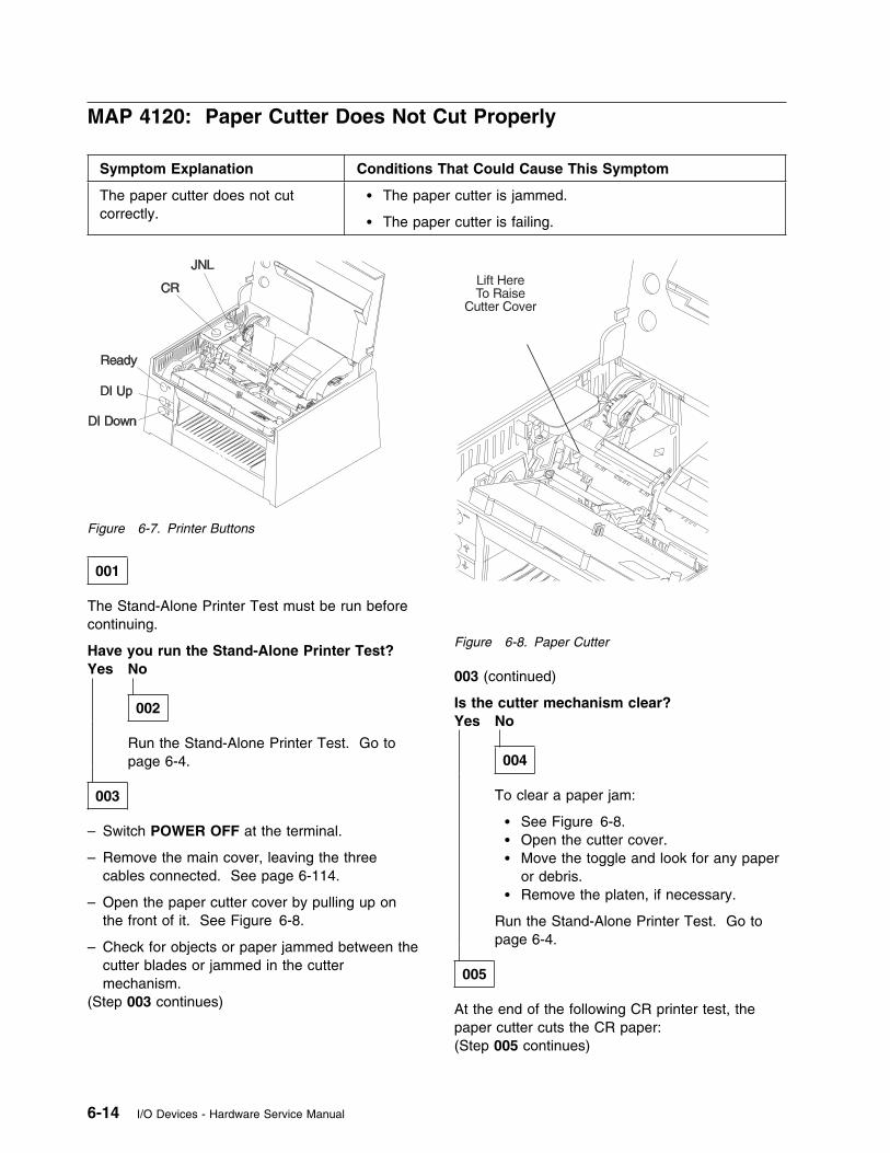
MAP 4120: Paper Cutter Does Not Cut Properly
Symptom Explanation Conditions That Could Cause This Symptom
The paper cutter does not cutcorrectly.
� The paper cutter is jammed.
� The paper cutter is failing.
Figure 6-7. Printer Buttons
001
The Stand-Alone Printer Test must be run beforecontinuing.
Have you run the Stand-Alone Printer Test?Yes No
002
Run the Stand-Alone Printer Test. Go topage 6-4.
003
– Switch POWER OFF at the terminal.
– Remove the main cover, leaving the threecables connected. See page 6-114.
– Open the paper cutter cover by pulling up onthe front of it. See Figure 6-8.
– Check for objects or paper jammed between thecutter blades or jammed in the cuttermechanism.
(Step 003 continues)
Figure 6-8. Paper Cutter
003 (continued)
Is the cutter mechanism clear?Yes No
004
To clear a paper jam:
� See Figure 6-8.� Open the cutter cover.� Move the toggle and look for any paper
or debris.� Remove the platen, if necessary.
Run the Stand-Alone Printer Test. Go topage 6-4.
005
At the end of the following CR printer test, thepaper cutter cuts the CR paper:(Step 005 continues)
6-14 I/O Devices - Hardware Service Manual
005 (continued)
– Switch power ON at the terminal.
– Press and hold the Ready button. SeeFigure 6-7 on page 6-14.
– Press the CR button.
– Release both buttons.
– While observing the paper cutter, press theReady button.
The paper cutter gears, (1) in Figure 6-8 onpage 6-14, should move smoothly and the papercutter blades should completely retract.
Did the paper cutter operate correctly?Yes No
006
Exchange the paper cutter. See page 6-87.
007
The paper cutter is working correctly.
Run the Stand-Alone Printer test. See page 6-4.
Chapter 6. Point-of-Sale Printer Models 3, 3R, 4, 4A, 4R 6-15
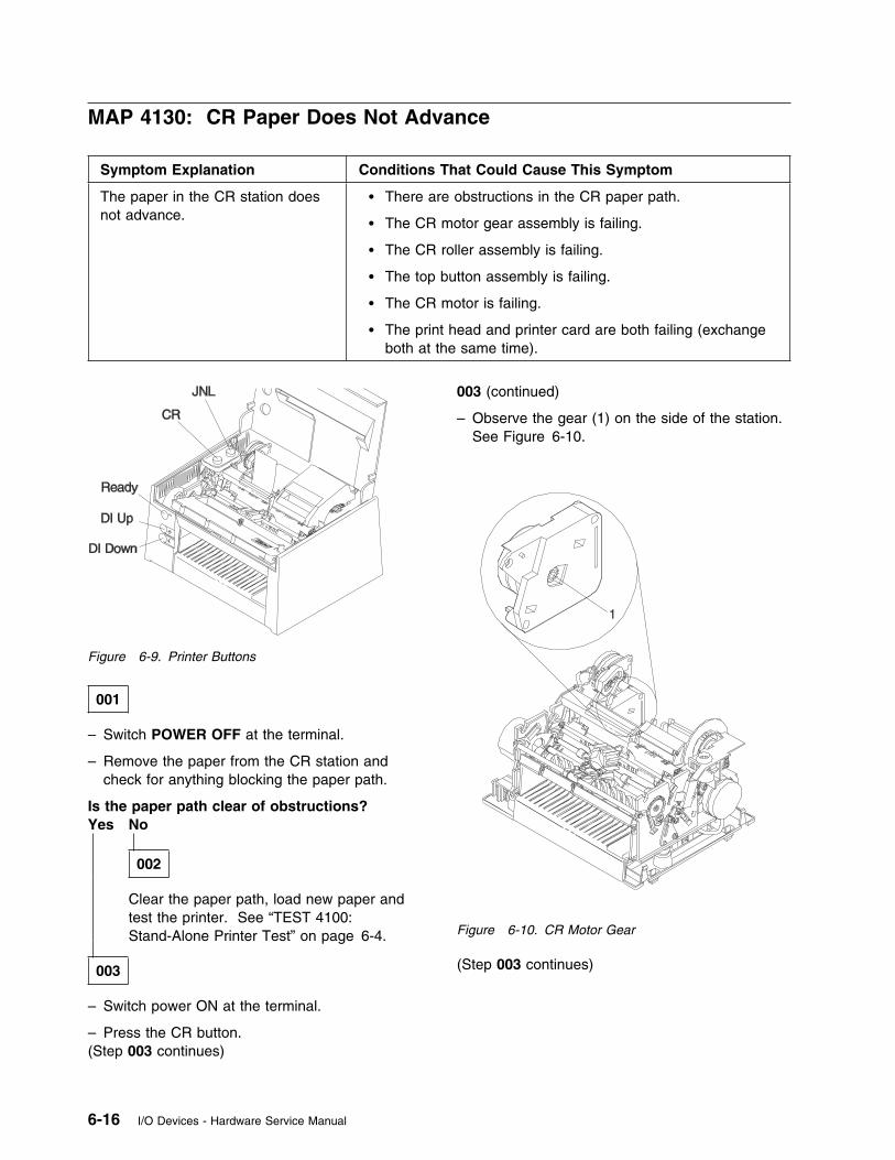
MAP 4130: CR Paper Does Not Advance
Symptom Explanation Conditions That Could Cause This Symptom
The paper in the CR station doesnot advance.
� There are obstructions in the CR paper path.
� The CR motor gear assembly is failing.
� The CR roller assembly is failing.
� The top button assembly is failing.
� The CR motor is failing.
� The print head and printer card are both failing (exchangeboth at the same time).
Figure 6-9. Printer Buttons
001
– Switch POWER OFF at the terminal.
– Remove the paper from the CR station andcheck for anything blocking the paper path.
Is the paper path clear of obstructions?Yes No
002
Clear the paper path, load new paper andtest the printer. See “TEST 4100:Stand-Alone Printer Test” on page 6-4.
003
– Switch power ON at the terminal.
– Press the CR button.(Step 003 continues)
003 (continued)
– Observe the gear (1) on the side of the station.See Figure 6-10.
1
Figure 6-10. CR Motor Gear
(Step 003 continues)
6-16 I/O Devices - Hardware Service Manual
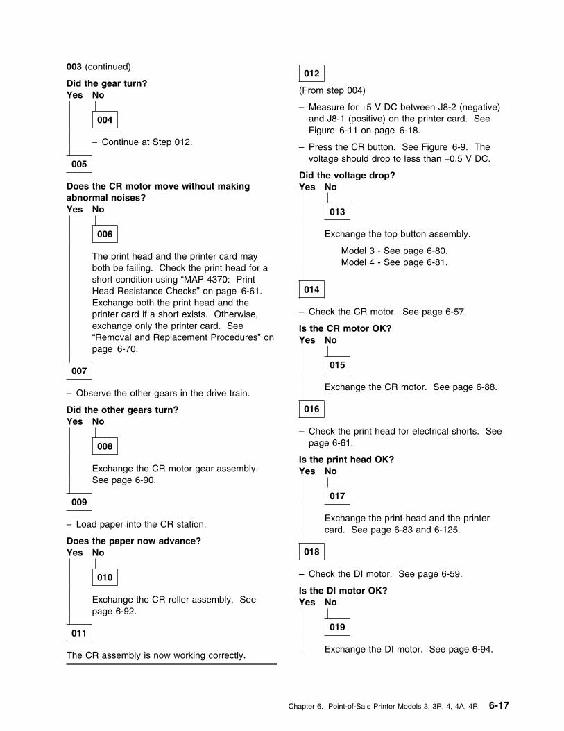
003 (continued)
Did the gear turn?Yes No
004
– Continue at Step 012.
005
Does the CR motor move without makingabnormal noises?Yes No
006
The print head and the printer card mayboth be failing. Check the print head for ashort condition using “MAP 4370: PrintHead Resistance Checks” on page 6-61.Exchange both the print head and theprinter card if a short exists. Otherwise,exchange only the printer card. See“Removal and Replacement Procedures” onpage 6-70.
007
– Observe the other gears in the drive train.
Did the other gears turn?Yes No
008
Exchange the CR motor gear assembly.See page 6-90.
009
– Load paper into the CR station.
Does the paper now advance?Yes No
010
Exchange the CR roller assembly. Seepage 6-92.
011
The CR assembly is now working correctly.
012
(From step 004)
– Measure for +5 V DC between J8-2 (negative)and J8-1 (positive) on the printer card. SeeFigure 6-11 on page 6-18.
– Press the CR button. See Figure 6-9. Thevoltage should drop to less than +0.5 V DC.
Did the voltage drop?Yes No
013
Exchange the top button assembly.
Model 3 - See page 6-80.Model 4 - See page 6-81.
014
– Check the CR motor. See page 6-57.
Is the CR motor OK?Yes No
015
Exchange the CR motor. See page 6-88.
016
– Check the print head for electrical shorts. Seepage 6-61.
Is the print head OK?Yes No
017
Exchange the print head and the printercard. See page 6-83 and 6-125.
018
– Check the DI motor. See page 6-59.
Is the DI motor OK?Yes No
019
Exchange the DI motor. See page 6-94.
Chapter 6. Point-of-Sale Printer Models 3, 3R, 4, 4A, 4R 6-17
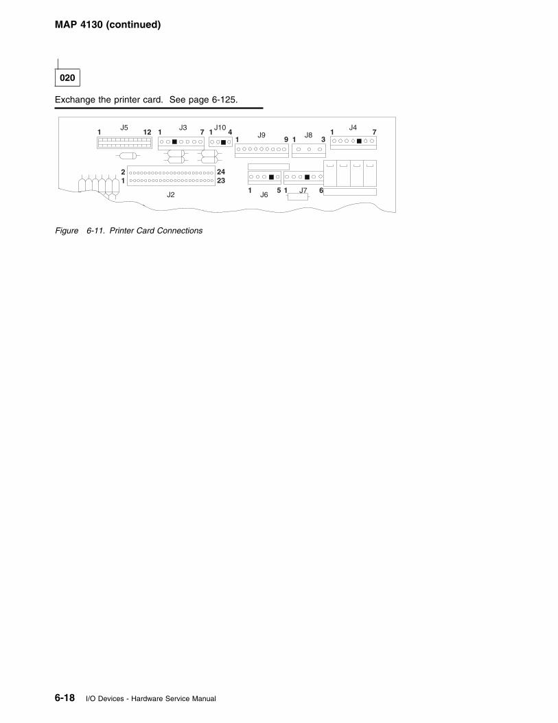
MAP 4130 (continued)
020
Exchange the printer card. See page 6-125.
1J5
12 1J3
7
21
2423
J10
1J9 9 1
1 5 1J6
J7 6
31
J47J81 4
J2
Figure 6-11. Printer Card Connections
6-18 I/O Devices - Hardware Service Manual
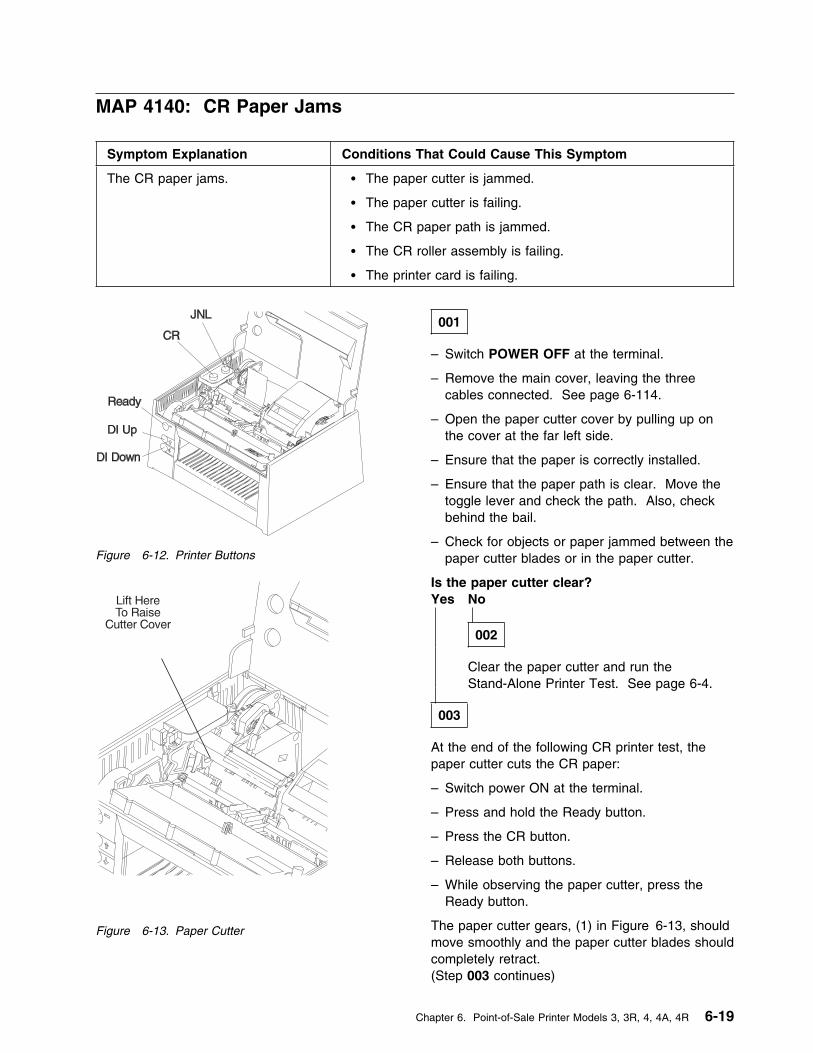
MAP 4140: CR Paper Jams
Symptom Explanation Conditions That Could Cause This Symptom
The CR paper jams. � The paper cutter is jammed.
� The paper cutter is failing.
� The CR paper path is jammed.
� The CR roller assembly is failing.
� The printer card is failing.
Figure 6-12. Printer Buttons
Figure 6-13. Paper Cutter
001
– Switch POWER OFF at the terminal.
– Remove the main cover, leaving the threecables connected. See page 6-114.
– Open the paper cutter cover by pulling up onthe cover at the far left side.
– Ensure that the paper is correctly installed.
– Ensure that the paper path is clear. Move thetoggle lever and check the path. Also, checkbehind the bail.
– Check for objects or paper jammed between thepaper cutter blades or in the paper cutter.
Is the paper cutter clear?Yes No
002
Clear the paper cutter and run theStand-Alone Printer Test. See page 6-4.
003
At the end of the following CR printer test, thepaper cutter cuts the CR paper:
– Switch power ON at the terminal.
– Press and hold the Ready button.
– Press the CR button.
– Release both buttons.
– While observing the paper cutter, press theReady button.
The paper cutter gears, (1) in Figure 6-13, shouldmove smoothly and the paper cutter blades shouldcompletely retract.(Step 003 continues)
Chapter 6. Point-of-Sale Printer Models 3, 3R, 4, 4A, 4R 6-19
MAP 4140 (continued)
003 (continued)
Did the paper cutter operate correctly?Yes No
004
Exchange the paper cutter. See page 6-87.
– or –
Exchange the printer card. See page6-125.
005
Exchange the CR roller assembly. See page6-92.
6-20 I/O Devices - Hardware Service Manual
MAP 4150: CR Station is Overprinting
Symptom Explanation Conditions That Could Cause This Symptom
The CR station is overprinting. � The CR paper rollers are failing.
� The CR paper is jammed.
� The CR motor is failing.
� The CR motor gear assembly is failing.
� The CR roller assembly is failing.
� The printer card is failing.
001
The Stand-Alone Printer Test must be run beforecontinuing.
Have you run the Stand-Alone Printer Test?Yes No
002
Run the Stand-Alone Printer Test. Seepage 6-4.
003
– Lift the paper roll and check that the blue paperrollers in the bottom of the CR station turnfreely.
Do the paper rollers turn freely?Yes No
004
Oil the paper rollers.
– or –
Exchange the paper rollers. See page6-113.
005
– Ensure that the paper is correctly installed andmoves freely through the printer withoutjamming.
(Step 005 continues)
005 (continued)
Is the CR paper moving freely through theprinter?Yes No
006
See page 6-19.
007
– Check the CR motor. See page 6-57.
Is the CR motor OK?Yes No
008
Check the print head for a short condition.Use “MAP 4370: Print Head ResistanceChecks” on page 6-61. Exchange both theprint head and the printer card if a shortexists. Otherwise, exchange only printercard. See page 6-125 and 6-83.
– or –
Exchange the CR motor. See page 6-88.
009
Exchange the CR motor gear assembly. Seepage 6-90.
– or –
Exchange the CR roller assembly. See page6-92.
Chapter 6. Point-of-Sale Printer Models 3, 3R, 4, 4A, 4R 6-21
MAP 4160: DI Paper Advances Continuously
Symptom Explanation Conditions That Could Cause This Symptom
The paper in the DI stationadvances continuously.
� The front button assembly is failing.
� The printer card is failing.
001
– Switch POWER OFF at the terminal.
– Remove the main cover, leaving the threecables connected. See page 6-114.
– Disconnect cable J9 from the printer card.
Did the paper stop advancing?Yes No
002
Exchange the printer card. See page6-125.
003
Exchange the front button assembly. See page6-74.
6-22 I/O Devices - Hardware Service Manual
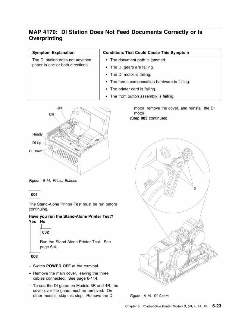
MAP 4170: DI Station Does Not Feed Documents Correctly or IsOverprinting
Symptom Explanation Conditions That Could Cause This Symptom
The DI station does not advancepaper in one or both directions.
� The document path is jammed.
� The DI gears are failing.
� The DI motor is failing.
� The forms compensation hardware is failing.
� The printer card is failing.
� The front button assembly is failing.
Figure 6-14. Printer Buttons
001
The Stand-Alone Printer Test must be run beforecontinuing.
Have you run the Stand-Alone Printer Test?Yes No
002
Run the Stand-Alone Printer Test. Seepage 6-4.
003
– Switch POWER OFF at the terminal.
– Remove the main cover, leaving the threecables connected. See page 6-114.
– To see the DI gears on Models 3R and 4R, thecover over the gears must be removed. Onother models, skip this step. Remove the DI
motor, remove the cover, and reinstall the DImotor.
(Step 003 continues)
2
1
Figure 6-15. DI Gears
Chapter 6. Point-of-Sale Printer Models 3, 3R, 4, 4A, 4R 6-23
MAP 4170 (continued)
003 (continued)
– Switch power ON.
– Press the DI up button. See Figure 6-14.
– Ensure that the gears, (2) in Figure 6-15, rotateand that there is no damage to their teeth.
– Ensure that the DI shaft, (1) in Figure 6-15, isnot slipping and rotating inside the gear.
– Check the same conditions as above whilepressing the DI down button (5).
Is the document path clear of obstructions?Yes No
004
– On Models 3R and 4R, reinstall the coverover the DI gears.
Clear the document path. Check for debrisinside the acoustic flap and around therollers, DI guide, and sensors. Run theStand-Alone Printer Test. See page 6-4.
005
Did at least one of the DI gears turn?Yes No
006
– On Models 3R and 4R, reinstall the coverover the DI gears.
– Continue at Step 014 on page 6-25.
007
Do all the DI gears rotate?Yes No
008
Exchange the DI gears. See page 6-96.
009
– On Models 3R and 4R, reinstall the cover overthe DI gears.
– Check the DI motor. See page 6-59.(Step 009 continues)
009 (continued)
Is the motor OK?Yes No
010
Exchange the DI motor. See page 6-94.
011
– Pull the forms compensation shaft forwardtoward the front of the printer and then allow itto return to its original position. Move the formscompensation shaft using lever (1) inFigure 6-16.
– Slip a piece of paper under the four metalrollers on the shaft, (2) in Figure 6-16.
Does the paper slip under the paper rollers?Yes No
012
Check for objects that may be obstructingthe paper rollers.
– or –
The forms compensation hardware is failing.Make sure that nothing is blocking the formscompensation hardware. Call your supportorganization for assistance.
013
Exchange the printer card. See page 6-125.
6-24 I/O Devices - Hardware Service Manual
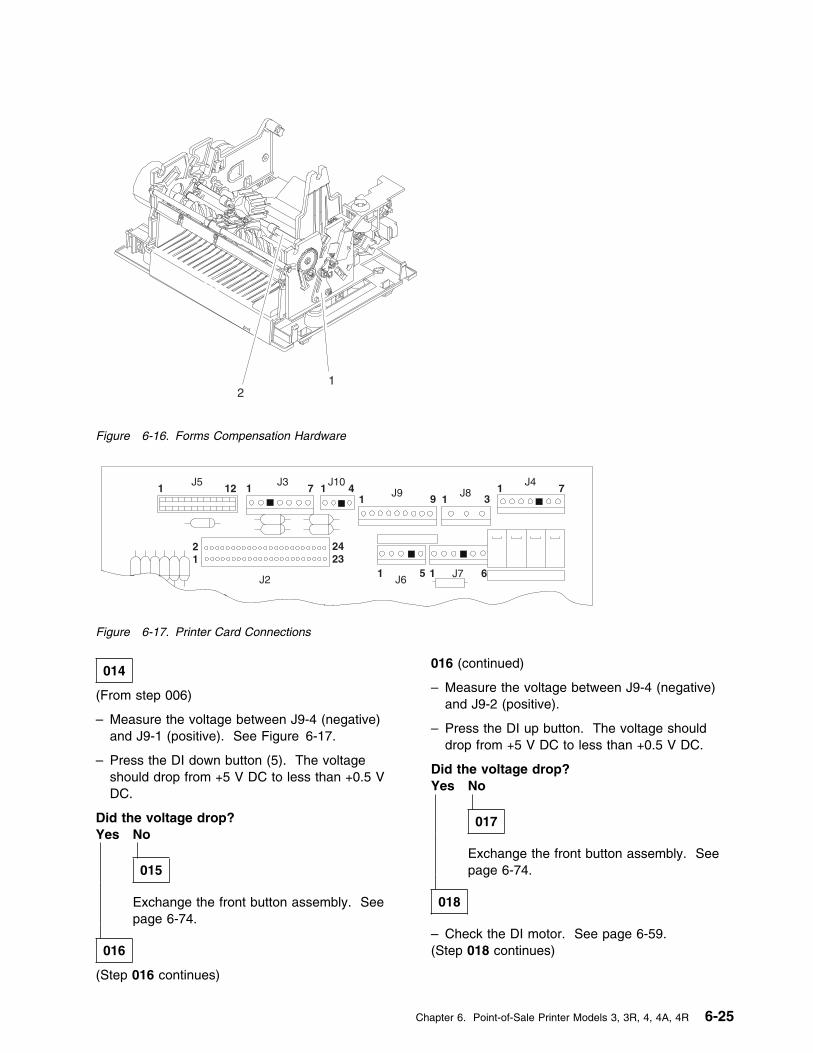
21
Figure 6-16. Forms Compensation Hardware
1J5
12 1J3
7
21
2423
J10
1J9 9 1
1 5 1J6
J7 6
31
J47J81 4
J2
Figure 6-17. Printer Card Connections
014
(From step 006)
– Measure the voltage between J9-4 (negative)and J9-1 (positive). See Figure 6-17.
– Press the DI down button (5). The voltageshould drop from +5 V DC to less than +0.5 VDC.
Did the voltage drop?Yes No
015
Exchange the front button assembly. Seepage 6-74.
016
(Step 016 continues)
016 (continued)
– Measure the voltage between J9-4 (negative)and J9-2 (positive).
– Press the DI up button. The voltage shoulddrop from +5 V DC to less than +0.5 V DC.
Did the voltage drop?Yes No
017
Exchange the front button assembly. Seepage 6-74.
018
– Check the DI motor. See page 6-59.(Step 018 continues)
Chapter 6. Point-of-Sale Printer Models 3, 3R, 4, 4A, 4R 6-25

MAP 4170 (continued)
018 (continued)
Is the motor OK?Yes No
019
Exchange the DI motor. See page 6-94.
020
Exchange the printer card. See page 6-125.
6-26 I/O Devices - Hardware Service Manual
MAP 4180: Home Errors
Symptom Explanation Conditions That Could Cause This Symptom
The print head is not reaching thecenter of the home sensor whenexpected or it reaches the homesensor too soon.
� The home sensor is blocked by debris or dust.
� The print head path is blocked.
� The home sensor card is failing.
� The transport motor is failing.
� The printer card is failing.
� The helix and nut are worn.
� The ribbon drive clutch is failing.
001
– Clean the sensors on the home sensor card.See page 6-66.
Does the printer still fail?Yes No
002
The printer is now running correctly.
003
– Ensure that the toggle levers for the CR stationand the JNL station are pushed toward the rearof the printer.
– Ensure that the printer ribbon cartridge isinstalled correctly and advances when the printhead moves.
– Ensure that the print head cable is routed belowthe home sensors.
– Check that the CR or JNL paper is not jammed.
– Switch POWER OFF at the terminal.
– Remove the main cover, leaving the threecables connected. See page 6-114.
– Ensure that the cable connecting the homesensor card to the printer card is plugged incorrectly at both ends.
– Move the print head all the way to the left andto the right.
(Step 003 continues)
003 (continued)
Does the print head move freely?Yes No
004
– Continue at Step 012 on page 6-28.
005
– Switch power ON at the terminal.
– See page 6-64 and perform the Home SensorCheck to verify that the home sensor card isoperating correctly.
Is the home sensor card OK?Yes No
006
Exchange the home sensor card. See page6-118.
– or –
Exchange the home sensor card cable.
007
– Switch POWER OFF at the terminal.
– Remove the printer ribbon cartridge.
– Check the transport motor resistance. Seepage 6-62.
(Step 007 continues)
Chapter 6. Point-of-Sale Printer Models 3, 3R, 4, 4A, 4R 6-27
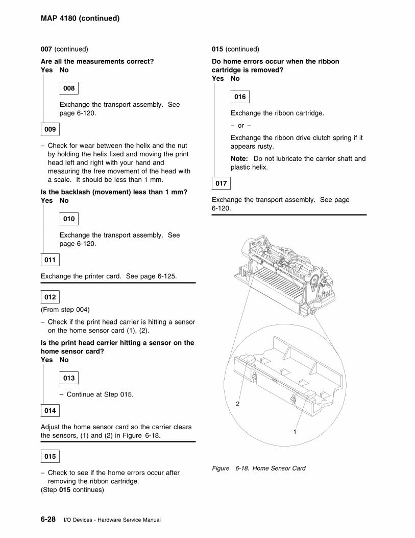
MAP 4180 (continued)
007 (continued)
Are all the measurements correct?Yes No
008
Exchange the transport assembly. Seepage 6-120.
009
– Check for wear between the helix and the nutby holding the helix fixed and moving the printhead left and right with your hand andmeasuring the free movement of the head witha scale. It should be less than 1 mm.
Is the backlash (movement) less than 1 mm?Yes No
010
Exchange the transport assembly. Seepage 6-120.
011
Exchange the printer card. See page 6-125.
012
(From step 004)
– Check if the print head carrier is hitting a sensoron the home sensor card (1), (2).
Is the print head carrier hitting a sensor on thehome sensor card?Yes No
013
– Continue at Step 015.
014
Adjust the home sensor card so the carrier clearsthe sensors, (1) and (2) in Figure 6-18.
015
– Check to see if the home errors occur afterremoving the ribbon cartridge.
(Step 015 continues)
015 (continued)
Do home errors occur when the ribboncartridge is removed?Yes No
016
Exchange the ribbon cartridge.
– or –
Exchange the ribbon drive clutch spring if itappears rusty.
Note: Do not lubricate the carrier shaft andplastic helix.
017
Exchange the transport assembly. See page6-120.
2
1
Figure 6-18. Home Sensor Card
6-28 I/O Devices - Hardware Service Manual
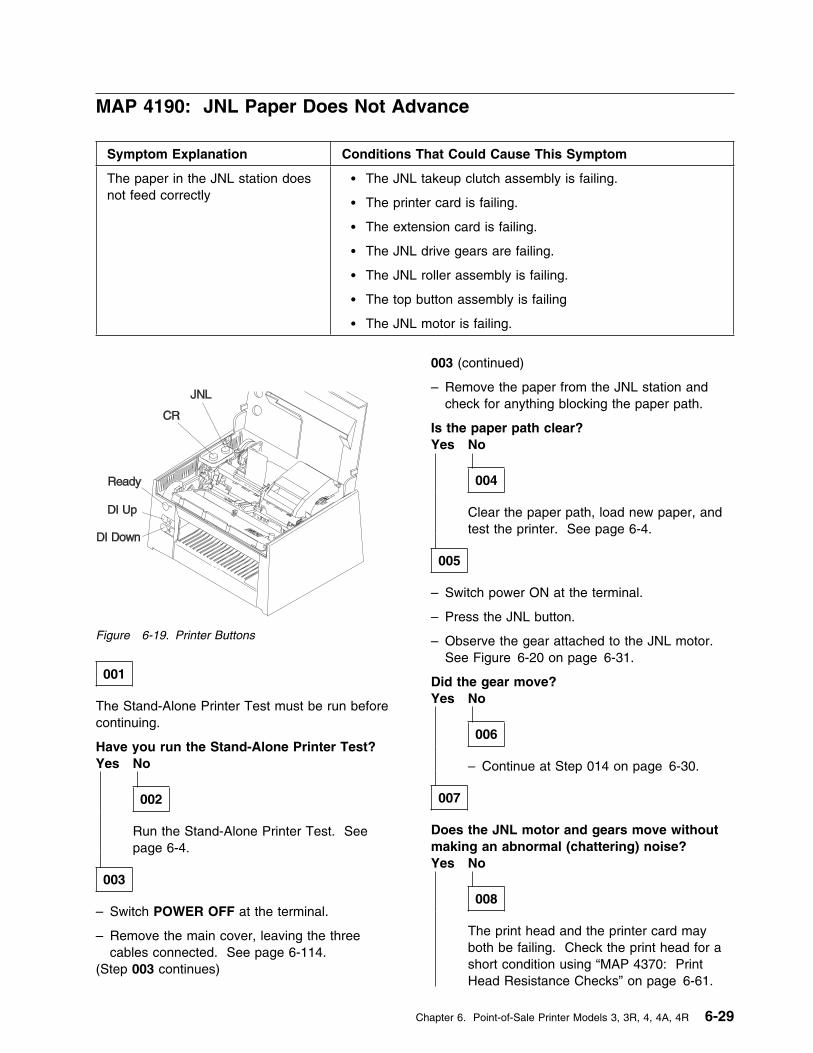
MAP 4190: JNL Paper Does Not Advance
Symptom Explanation Conditions That Could Cause This Symptom
The paper in the JNL station doesnot feed correctly
� The JNL takeup clutch assembly is failing.
� The printer card is failing.
� The extension card is failing.
� The JNL drive gears are failing.
� The JNL roller assembly is failing.
� The top button assembly is failing
� The JNL motor is failing.
Figure 6-19. Printer Buttons
001
The Stand-Alone Printer Test must be run beforecontinuing.
Have you run the Stand-Alone Printer Test?Yes No
002
Run the Stand-Alone Printer Test. Seepage 6-4.
003
– Switch POWER OFF at the terminal.
– Remove the main cover, leaving the threecables connected. See page 6-114.
(Step 003 continues)
003 (continued)
– Remove the paper from the JNL station andcheck for anything blocking the paper path.
Is the paper path clear?Yes No
004
Clear the paper path, load new paper, andtest the printer. See page 6-4.
005
– Switch power ON at the terminal.
– Press the JNL button.
– Observe the gear attached to the JNL motor.See Figure 6-20 on page 6-31.
Did the gear move?Yes No
006
– Continue at Step 014 on page 6-30.
007
Does the JNL motor and gears move withoutmaking an abnormal (chattering) noise?Yes No
008
The print head and the printer card mayboth be failing. Check the print head for ashort condition using “MAP 4370: PrintHead Resistance Checks” on page 6-61.
Chapter 6. Point-of-Sale Printer Models 3, 3R, 4, 4A, 4R 6-29
MAP 4190 (continued)
Exchange both the print head and theprinter card if a short exists. Otherwise,exchange only the printer card. See“Removal and Replacement Procedures” onpage 6-70.
009
– Observe the other gears in the drive train. SeeFigure 6-20 on page 6-31.
Do the other gears turn freely as opposed tostumbling from insufficient motor torque?Yes No
010
The JNL takeup clutch assembly or drivegears are failing. See page 6-104 andexchange the assembly.
011
– Load paper into the JNL station.
Does the paper now feed correctly?Yes No
012
Exchange the JNL roller assembly. Seepage 6-108.
013
The JNL station is working correctly.
014
(From step 006)
– Measure for +5 V DC between J8-2 (negative)and J8-3 (positive). See Figure 6-21 onpage 6-31.
– Press the JNL button. See Figure 6-19. Thevoltage should drop to less than +0.5 V DC.
Did the voltage drop?Yes No
015
Exchange the top button assembly.
(Step 015 continues)
015 (continued)Model 3 - See page 6-80.Model 4 - See page 6-81.
016
– Check the JNL motor for electrical shorts. Seepage 6-60.
Is the JNL motor OK?Yes No
017
Exchange the JNL motor. See page 6-105.
018
Exchange the printer card. See page 6-125.
– or –
Exchange the extension card. See page 6-127.
6-30 I/O Devices - Hardware Service Manual
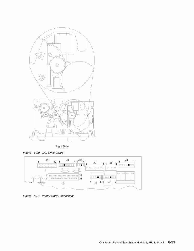
Right Side
Figure 6-20. JNL Drive Gears
1J5
12 1J3
7
21
2423
J10
1J9 9 1
1 5 1J6
J7 6
31
J47J81 4
J2
Figure 6-21. Printer Card Connections
Chapter 6. Point-of-Sale Printer Models 3, 3R, 4, 4A, 4R 6-31
MAP 4200: JNL Station Not Printing
Symptom Explanation Conditions That Could Cause This Symptom
The JNL station does not print.This is a paper movement error.
� The emitter O-ring is worn.
� The O-ring shaft is out of position.
� The JNL paper motion sensor is failing.
� The emitter O-ring has come off of the emitter wheel rim.
� The printer card is failing.
� The JNL roller assembly is failing.
� The JNL paper is jammed.
001
The Stand-Alone Printer Test must be run beforecontinuing.
Have you run the Stand-Alone Printer Test?Yes No
002
Run the Stand-Alone Printer Test. Seepage 6-4.
003
– Switch POWER OFF at the terminal andremove the main cover, leaving the three cablesconnected. See page 6-114.
– Switch power ON at the terminal and press theJNL button. See Figure 6-19 on page 6-29.
Did the JNL paper advance correctly?Yes No
004
Follow “MAP 4190: JNL Paper Does NotAdvance” on page 6-29.
005
– Check the JNL paper motion sensor. See page6-63.
Is the sensor OK?Yes No
006
Exchange the JNL paper motion sensor.See page 6-106.
007
– See Figure 6-22 on page 6-34.
– Ensure that the O-ring (1) that turns the emitterwheel is on the emitter wheel rim.
Is the O-ring on the emitter wheel rim OK?Yes No
008
Put the O-ring back on the emitter wheelrim. See Figure 6-22 on page 6-34.
009
– Ensure that the O-ring shaft is seated properly.The shaft should be held on both sides of theJNL roller. The O-ring shaft should move upand down in the slot near the O-ring as the JNLroller holder is toggled from the feed to the loadposition.
(Step 009 continues)
6-32 I/O Devices - Hardware Service Manual
009 (continued)
Is the O-ring shaft properly seated?Yes No
010
Exchange the JNL roller assembly. Seepage 6-108.
011
– Check the O-ring for wear. A worn O-ring oftenhas a large flat area.
Is the O-ring OK?Yes No
012
Exchange the JNL roller assembly. Seepage 6-108.
013
Exchange the printer card. See page 6-125.
Chapter 6. Point-of-Sale Printer Models 3, 3R, 4, 4A, 4R 6-33
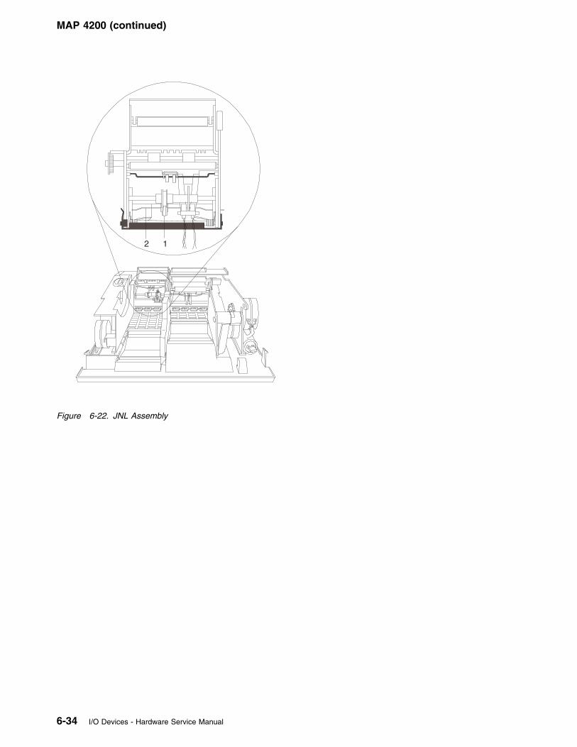
MAP 4200 (continued)
2 1
Figure 6-22. JNL Assembly
6-34 I/O Devices - Hardware Service Manual
MAP 4210: JNL Station is Overprinting
Symptom Explanation Conditions That Could Cause This Symptom
The JNL station is overprinting. � The JNL takeup clutch assembly is worn out.
� The JNL station rollers are failing.
� The JNL motor is failing.
� The JNL roller assembly is failing.
� The feed roller mechanism is worn out.
001
The Stand-Alone Printer Test must be run beforecontinuing.
Have you run the Stand-Alone Printer Test?Yes No
002
Run the Stand-Alone Printer Test. Seepage 6-4.
003
– Lift the paper roll and check that the blue paperrollers in the bottom of the JNL station turnfreely.
Did the blue paper rollers turn freely?Yes No
004
Exchange the paper rollers. See page6-113.
005
– Check the paper path for blockage.
Is the paper path OK?Yes No
006
Clear the paper path and retest the printer.
007
(Step 007 continues)
007 (continued)
– Switch POWER OFF at the terminal andremove the main cover, leaving the three cablesconnected. See page 6-114.
– Switch power ON at the terminal and press theJNL paper button while observing the JNLgears.
Do the JNL gears move freely as opposed tostumbling due to insufficient motor torque?Yes No
008
Exchange the JNL takeup clutch assembly.See page “Removing and Replacing theJNL Takeup Clutch, Gears, and Pawl” onpage 6-104.
– or –
The paper feed shafts may have excessivefriction. Exchange the JNL roller assembly.See page 6-108.
009
– Check the JNL motor. See page 6-60.
Is the JNL motor OK?Yes No
010
Exchange the JNL motor. See page 6-105.
011
Exchange the JNL roller assembly. See page6-108.
Chapter 6. Point-of-Sale Printer Models 3, 3R, 4, 4A, 4R 6-35
MAP 4220: MICR Does Not Read Correctly
Symptom Explanation Conditions That Could Cause This Symptom
The Magnetic Ink CharacterRecognition (MICR) reader doesnot read correctly.
� There is an obstruction in the check path.
� The MICR pressure pad is failing.
� The MICR read head is failing.
� The extension card is failing.
� The printer card is failing.
� The MICR read head magnet is failing.
The Stand-Alone Printer Test must be run beforecontinuing. See “TEST 4100: Stand-Alone PrinterTest” on page 6-4.
001
Have you run the Stand-Alone Printer Test?Yes No
002
– Run the Stand-Alone Printer Test to testthe basic functions of the printer beforetesting the MICR reader. See “TEST4100: Stand-Alone Printer Test” onpage 6-4.
003
This procedure assumes that the basic functionsof the printer have been tested and that the testwas successful.
– Perform the read head cleaning procedure andthen return to this procedure. See “MICR Headand Feed Rollers Cleaning Procedure” onpage 6-9.
– Run the Stand-Alone MICR Test and make thefollowing observations before continuing. Seepage 6-8.
1 The green indicator comes on when thecheck is inserted.
2 The check feeds into the printer when theReady (green) button is pressed for 3seconds.
3 The check reverses direction, is read, and
the correct characters are printed at theCR station.
4 The check moves smoothly through theread operation.
Did the green indicator come on when thecheck was inserted?Yes No
004
Go to “MAP 4290: Printer Indicator LightNot On When A Document Is Inserted” onpage 6-51 to continue isolation of thisfailure.
005
Did the check begin feeding into the printerwhen the Ready button was pressed for 3seconds?Yes No
006
Exchange the extension card first and thenif the test still fails, exchange the printercard. See “Removal and ReplacementProcedures” on page 6-70.
007
Did the check feed into the printer withoutjamming, skewing, or damaging the check?Yes No
008
(Step 008 continues)
6-36 I/O Devices - Hardware Service Manual
008 (continued)
Make sure that there is no paper or debrisblocking the check path.
– or –
Exchange the MICR pressure pad. Seepage 6-101.
009
Did the check reverse direction and feed outthe front of the printer?Yes No
010
Exchange the Upper DI Forms Sensor. Seepage 6-99.
011
Did any characters print at the CR station?Yes No
012
Make sure that the check being read doesnot have an amount field in the last 1 1/2inches of the check. This causes readingfailures. Try using a test check.
– or –
Make sure that the check was insertedcorrectly.
– or –
Exchange the MICR read head. See page6-100.
– or –
Exchange the extension card. See page6-127.
– or –
Exchange the printer card. See page6-125.
013
(Step 013 continues)
013 (continued)
Did all the correct characters print at the CRstation?Yes No
014
Make sure that the check was insertedcorrectly.
– or –
Make sure that the check being read doesnot have an amount field in the last 1 1/2inches of the check. This causes readingfailures. Try using a test check.
– or –
Magnetic interference from a nearby videodisplay, transformer, power supply, or otherelectrical device can cause MICR checkreading failures. If you experience thisproblem, try moving any suspected devicesaway from the printer as far as practical.
– or –
Exchange the MICR pressure pad. Seepage 6-101.
– or –
Exchange the DI gears. See page 6-96.
– or –
Exchange the MICR read head. See page6-100.
– or –
Exchange the MICR magnet. See page6-97.
– or –
Exchange the DI motor. See page 6-94.
– or –
Exchange the extension card. See page6-127.
– or –
Exchange the printer card. See page6-125.
015
(Step 015 continues)
Chapter 6. Point-of-Sale Printer Models 3, 3R, 4, 4A, 4R 6-37

MAP 4220 (continued)
015 (continued)
The problem may be intermittent. Run theStand-Alone MICR Test several times to ensurethat checks can now be read correctly. See“Stand-Alone MICR Test” on page 6-8.
– or –
Magnetic interference from a nearby video display,transformer, power supply, or other electricaldevice can cause MICR check reading failures. If
you experience this problem, try moving anysuspected devices away from the printer as far aspractical.
– or –
Make sure the customer checks that are failing toread are good quality checks.
– or –
Call your support organization for assistance.
6-38 I/O Devices - Hardware Service Manual
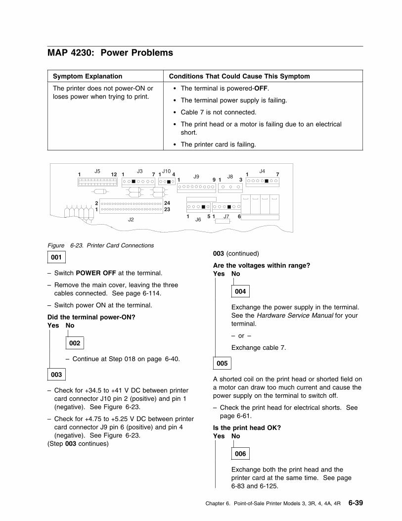
MAP 4230: Power Problems
Symptom Explanation Conditions That Could Cause This Symptom
The printer does not power-ON orloses power when trying to print.
� The terminal is powered-OFF.
� The terminal power supply is failing.
� Cable 7 is not connected.
� The print head or a motor is failing due to an electricalshort.
� The printer card is failing.
1J5
12 1J3
7
21
2423
J10
1J9 9 1
1 5 1J6
J7 6
31
J47J81 4
J2
Figure 6-23. Printer Card Connections
001
– Switch POWER OFF at the terminal.
– Remove the main cover, leaving the threecables connected. See page 6-114.
– Switch power ON at the terminal.
Did the terminal power-ON?Yes No
002
– Continue at Step 018 on page 6-40.
003
– Check for +34.5 to +41 V DC between printercard connector J10 pin 2 (positive) and pin 1(negative). See Figure 6-23.
– Check for +4.75 to +5.25 V DC between printercard connector J9 pin 6 (positive) and pin 4(negative). See Figure 6-23.
(Step 003 continues)
003 (continued)
Are the voltages within range?Yes No
004
Exchange the power supply in the terminal.See the Hardware Service Manual for yourterminal.
– or –
Exchange cable 7.
005
A shorted coil on the print head or shorted field ona motor can draw too much current and cause thepower supply on the terminal to switch off.
– Check the print head for electrical shorts. Seepage 6-61.
Is the print head OK?Yes No
006
Exchange both the print head and theprinter card at the same time. See page6-83 and 6-125.
Chapter 6. Point-of-Sale Printer Models 3, 3R, 4, 4A, 4R 6-39
MAP 4230 (continued)
007
– Check the CR motor for electrical shorts. Seepage 6-57.
Is the CR motor OK?Yes No
008
Exchange the CR motor. See page 6-88.
009
– Check the paper cutter motor for electricalshorts. See page 6-58.
Is the paper cutter motor OK?Yes No
010
Exchange the paper cutter motor. Seepage 6-87.
011
– Check the JNL motor for electrical shorts. Seepage 6-60.
Is the JNL motor OK?Yes No
012
Exchange the JNL motor. See page 6-105.
013
– Check the DI motor for electrical shorts. Seepage 6-59.
Is the DI motor OK?Yes No
014
Exchange the DI motor. See page 6-94.
015
– Check the transport motor for electrical shorts.See page 6-62.
(Step 015 continues)
015 (continued)
Is the transport motor OK?Yes No
016
Exchange the transport assembly. Seepage 6-120.
017
Exchange the printer card. See page 6-125.
018
(From step 002)
– Switch POWER OFF at the terminal.
– Unplug cable 7 from the printer.
– Switch power ON at the terminal.
Does the terminal power-ON?Yes No
019
Go to the Hardware Service Manual for yourterminal to isolate the power problem.
020
– Switch POWER OFF at the terminal.
– Unplug printer card connectors J2, J3, J4, J5,J6, J7, J8, J9, and J10.
– Reconnect cable 7 to the printer.
– Switch power ON at the terminal.
Does the terminal power-ON?Yes No
021
Exchange the printer card. See page6-125.
022
– Switch POWER OFF at the terminal.
– Reconnect J2.
– Switch power ON at the terminal.(Step 022 continues)
6-40 I/O Devices - Hardware Service Manual
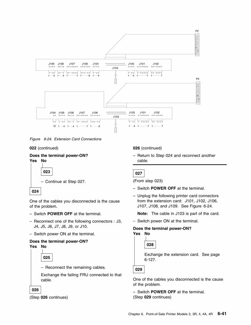
J102J101J105J104 J106J107J108J109
J103
1 141 6 1 14 141 7 77
P2
J102J101J105J104J106J107J108J109
J103
1 1 4141 6 1 14 141 7 77
P2
12
Figure 6-24. Extension Card Connections
022 (continued)
Does the terminal power-ON?Yes No
023
– Continue at Step 027.
024
One of the cables you disconnected is the causeof the problem.
– Switch POWER OFF at the terminal.
– Reconnect one of the following connectors : J3,J4, J5, J6, J7, J8, J9, or J10.
– Switch power ON at the terminal.
Does the terminal power-ON?Yes No
025
– Reconnect the remaining cables.
Exchange the failing FRU connected to thatcable.
026
(Step 026 continues)
026 (continued)
– Return to Step 024 and reconnect anothercable.
027
(From step 023)
– Switch POWER OFF at the terminal.
– Unplug the following printer card connectorsfrom the extension card: J101, J102, J106,J107, J108, and J109. See Figure 6-24.
Note: The cable in J103 is part of the card.
– Switch power ON at the terminal.
Does the terminal power-ON?Yes No
028
Exchange the extension card. See page6-127.
029
One of the cables you disconnected is the causeof the problem.
– Switch POWER OFF at the terminal.(Step 029 continues)
Chapter 6. Point-of-Sale Printer Models 3, 3R, 4, 4A, 4R 6-41

MAP 4230 (continued)
029 (continued)
– Reconnect one of the following connectors :J101, J102, J106, J107, J108, and J109.
– Switch power ON at the terminal.
Does the terminal power-ON?Yes No
030
– Reconnect the remaining cables.
Exchange the failing FRU connected to thatcable. See Table 6-6 on page 6-69.
031
– Return to Step 029 on page 6-41 andreconnect another cable.
6-42 I/O Devices - Hardware Service Manual
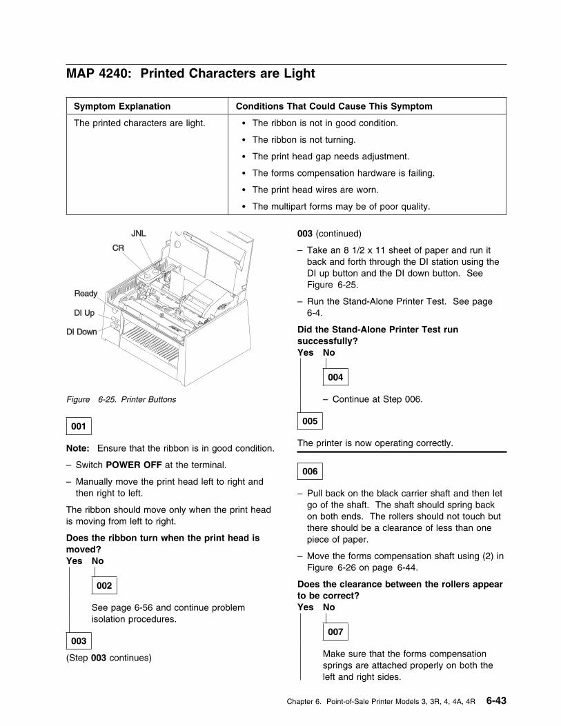
MAP 4240: Printed Characters are Light
Symptom Explanation Conditions That Could Cause This Symptom
The printed characters are light. � The ribbon is not in good condition.
� The ribbon is not turning.
� The print head gap needs adjustment.
� The forms compensation hardware is failing.
� The print head wires are worn.
� The multipart forms may be of poor quality.
Figure 6-25. Printer Buttons
001
Note: Ensure that the ribbon is in good condition.
– Switch POWER OFF at the terminal.
– Manually move the print head left to right andthen right to left.
The ribbon should move only when the print headis moving from left to right.
Does the ribbon turn when the print head ismoved?Yes No
002
See page 6-56 and continue problemisolation procedures.
003
(Step 003 continues)
003 (continued)
– Take an 8 1/2 x 11 sheet of paper and run itback and forth through the DI station using theDI up button and the DI down button. SeeFigure 6-25.
– Run the Stand-Alone Printer Test. See page6-4.
Did the Stand-Alone Printer Test runsuccessfully?Yes No
004
– Continue at Step 006.
005
The printer is now operating correctly.
006
– Pull back on the black carrier shaft and then letgo of the shaft. The shaft should spring backon both ends. The rollers should not touch butthere should be a clearance of less than onepiece of paper.
– Move the forms compensation shaft using (2) inFigure 6-26 on page 6-44.
Does the clearance between the rollers appearto be correct?Yes No
007
Make sure that the forms compensationsprings are attached properly on both theleft and right sides.
Chapter 6. Point-of-Sale Printer Models 3, 3R, 4, 4A, 4R 6-43

MAP 4240 (continued)
21
Figure 6-26. Forms Compensation Hardware
– or –
The forms compensation hardware is failing.Call your support organization forassistance.
008
Readjust the print head gap and perform only theadjustment steps. See page 6-83.
– or –
Exchange the print head. See page 6-83.
6-44 I/O Devices - Hardware Service Manual
MAP 4250: Printed Characters Missing One or More Dot Rows
Symptom Explanation Conditions That Could Cause This Symptom
One or more wires are not firing onthe print head.
� The print head is failing.
� The printer card is failing.
� The CR motor is failing.
� The paper cutter motor is failing.
� The JNL motor is failing.
� The DI motor is failing.
001
– Check the print head resistance. See page6-61.
Is the print head OK?Yes No
002
Was the resistance low?Yes No
003
Exchange the print head. See page6-83.
004
Exchange the print head. See page 6-83.
- and -
Exchange the printer card. See page6-125.
005
– Check the CR motor for electrical shorts. Seepage 6-57.
Is the CR motor OK?Yes No
006
Exchange the CR motor. See page 6-88.
007
– Check the paper cutter motor for electricalshorts. See page 6-58.
Is the paper cutter motor OK?Yes No
008
Exchange the paper cutter motor. Seepage 6-87.
009
– Check the JNL motor for electrical shorts. Seepage 6-60.
Is the JNL motor OK?Yes No
010
Exchange the JNL motor. See page 6-105.
Chapter 6. Point-of-Sale Printer Models 3, 3R, 4, 4A, 4R 6-45

MAP 4250 (continued)
011
– Check the DI motor for electrical shorts. Seepage 6-59.
Is the DI motor OK?Yes No
012
Exchange the DI motor. See page 6-94.
013
Exchange the print head. See page 6-83.
– or –
Exchange the printer card. See page 6-125.
6-46 I/O Devices - Hardware Service Manual
MAP 4260: Printed Characters Are Smudged
Symptom Explanation Conditions That Could Cause This Symptom
The printed characters aresmudged.
� The print head gap needs adjustment.
� The print head is failing.
� The ribbon cartridge is failing.
� The forms compensation hardware is failing.
001
– Check the ribbon cartridge.
Is the ribbon cartridge OK?Yes No
002
– Exchange the ribbon cartridge.
003
– Check the print head gap and perform the printhead gap adjustment procedures. See page6-83.
Is the print head gap OK?Yes No
004
Adjust the print head gap. See page 6-83.
005
Call your support organization for assistance.
Chapter 6. Point-of-Sale Printer Models 3, 3R, 4, 4A, 4R 6-47
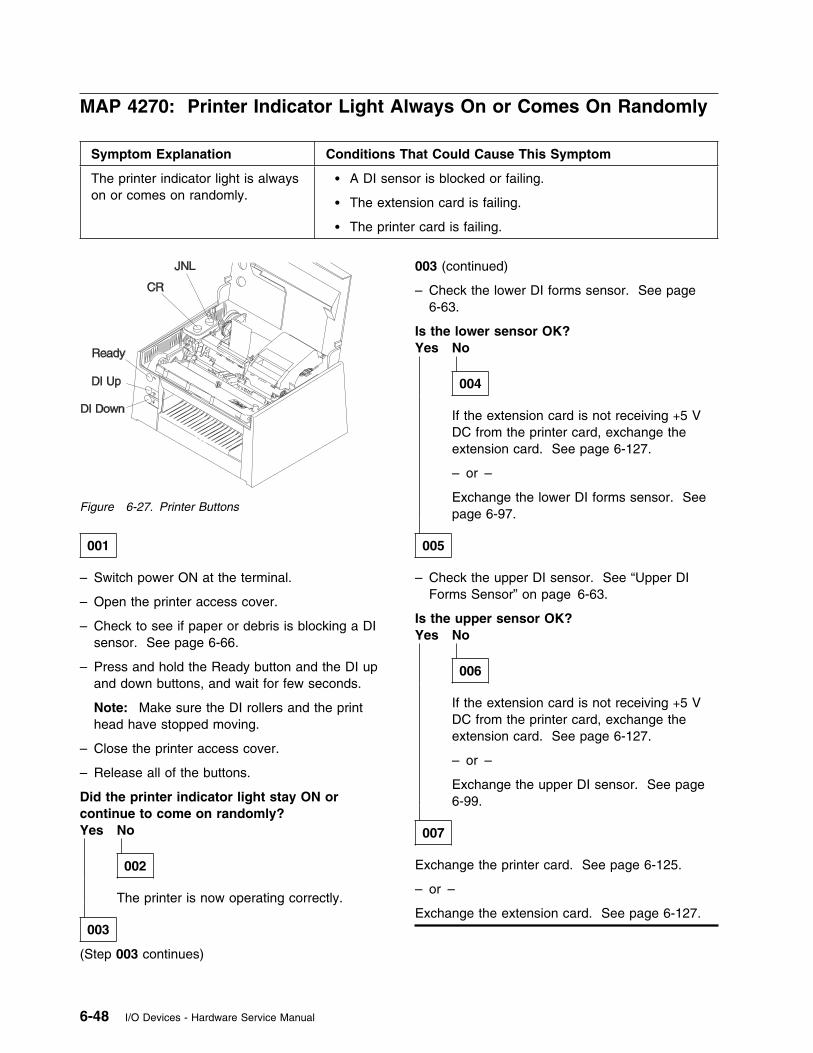
MAP 4270: Printer Indicator Light Always On or Comes On Randomly
Symptom Explanation Conditions That Could Cause This Symptom
The printer indicator light is alwayson or comes on randomly.
� A DI sensor is blocked or failing.
� The extension card is failing.
� The printer card is failing.
Figure 6-27. Printer Buttons
001
– Switch power ON at the terminal.
– Open the printer access cover.
– Check to see if paper or debris is blocking a DIsensor. See page 6-66.
– Press and hold the Ready button and the DI upand down buttons, and wait for few seconds.
Note: Make sure the DI rollers and the printhead have stopped moving.
– Close the printer access cover.
– Release all of the buttons.
Did the printer indicator light stay ON orcontinue to come on randomly?Yes No
002
The printer is now operating correctly.
003
(Step 003 continues)
003 (continued)
– Check the lower DI forms sensor. See page6-63.
Is the lower sensor OK?Yes No
004
If the extension card is not receiving +5 VDC from the printer card, exchange theextension card. See page 6-127.
– or –
Exchange the lower DI forms sensor. Seepage 6-97.
005
– Check the upper DI sensor. See “Upper DIForms Sensor” on page 6-63.
Is the upper sensor OK?Yes No
006
If the extension card is not receiving +5 VDC from the printer card, exchange theextension card. See page 6-127.
– or –
Exchange the upper DI sensor. See page6-99.
007
Exchange the printer card. See page 6-125.
– or –
Exchange the extension card. See page 6-127.
6-48 I/O Devices - Hardware Service Manual
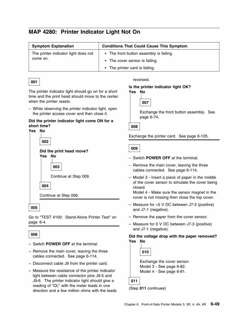
MAP 4280: Printer Indicator Light Not On
Symptom Explanation Conditions That Could Cause This Symptom
The printer indicator light does notcome on.
� The front button assembly is failing.
� The cover sensor is failing.
� The printer card is failing.
001
The printer indicator light should go on for a shorttime and the print head should move to the centerwhen the printer resets.
– While observing the printer indicator light, openthe printer access cover and then close it.
Did the printer indicator light come ON for ashort time?Yes No
002
Did the print head move?Yes No
003
Continue at Step 009.
004
Continue at Step 006.
005
Go to “TEST 4100: Stand-Alone Printer Test” onpage 6-4.
006
– Switch POWER OFF at the terminal.
– Remove the main cover, leaving the threecables connected. See page 6-114.
– Disconnect cable J9 from the printer card.
– Measure the resistance of the printer indicatorlight between cable connector pins J9-5 andJ9-6. The printer indicator light should give areading of “OL” with the meter leads in onedirection and a few million ohms with the leads
reversed.
Is the printer indicator light OK?Yes No
007
Exchange the front button assembly. Seepage 6-74.
008
Exchange the printer card. See page 6-125.
009
– Switch POWER OFF at the terminal.
– Remove the main cover, leaving the threecables connected. See page 6-114.
– Model 3 - Insert a piece of paper in the middleof the cover sensor to simulate the cover beingclosed.Model 4 - Make sure the sensor magnet in thecover is not missing then close the top cover.
– Measure for +5 V DC between J7-3 (positive)and J7-1 (negative).
– Remove the paper from the cover sensor.
– Measure for 0 V DC between J7-3 (positive)and J7-1 (negative).
Did the voltage drop with the paper removed?Yes No
010
Exchange the cover sensor.Model 3 - See page 6-82.Model 4 - See page 6-81.
011
(Step 011 continues)
Chapter 6. Point-of-Sale Printer Models 3, 3R, 4, 4A, 4R 6-49
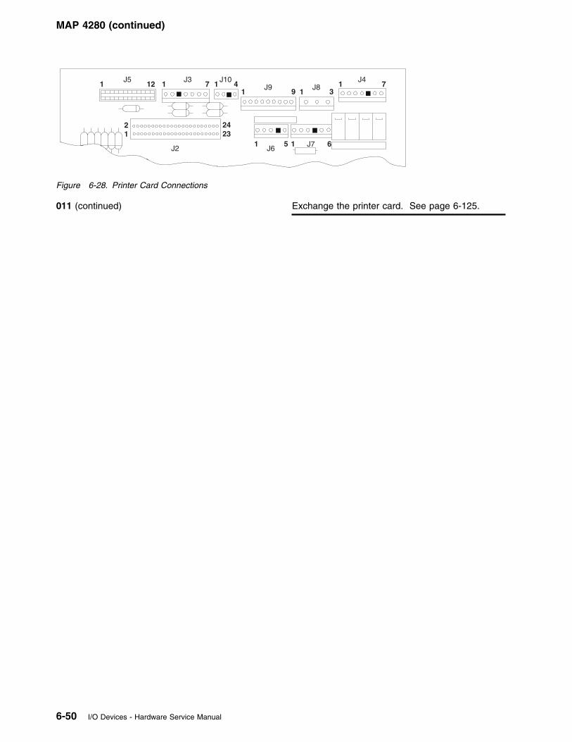
MAP 4280 (continued)
1J5
12 1J3
7
21
2423
J10
1J9 9 1
1 5 1J6
J7 6
31
J47J81 4
J2
Figure 6-28. Printer Card Connections
011 (continued) Exchange the printer card. See page 6-125.
6-50 I/O Devices - Hardware Service Manual
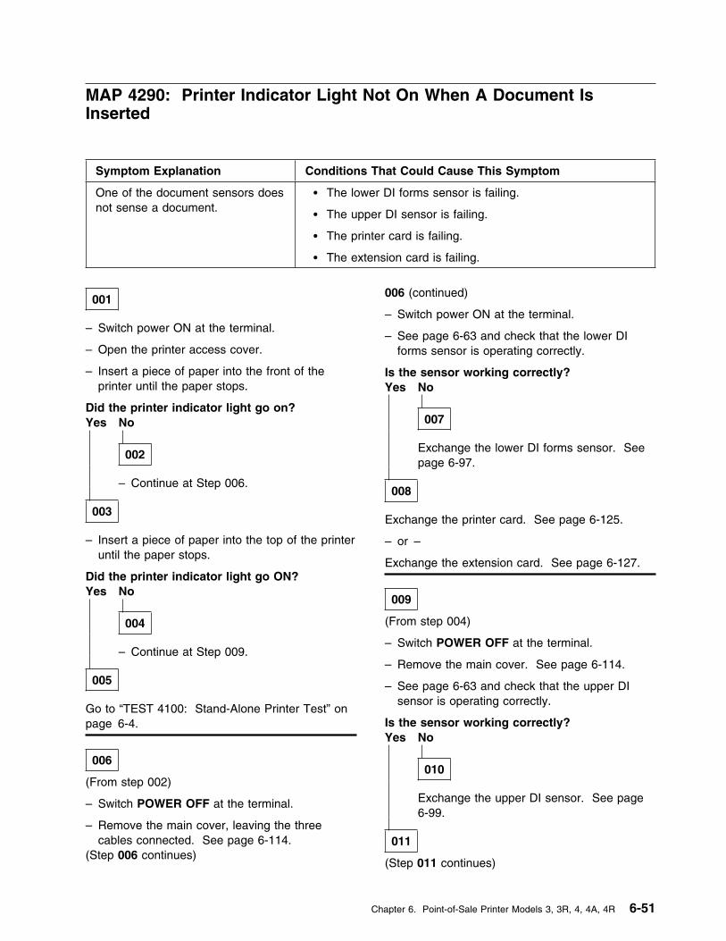
MAP 4290: Printer Indicator Light Not On When A Document IsInserted
Symptom Explanation Conditions That Could Cause This Symptom
One of the document sensors doesnot sense a document.
� The lower DI forms sensor is failing.
� The upper DI sensor is failing.
� The printer card is failing.
� The extension card is failing.
001
– Switch power ON at the terminal.
– Open the printer access cover.
– Insert a piece of paper into the front of theprinter until the paper stops.
Did the printer indicator light go on?Yes No
002
– Continue at Step 006.
003
– Insert a piece of paper into the top of the printeruntil the paper stops.
Did the printer indicator light go ON?Yes No
004
– Continue at Step 009.
005
Go to “TEST 4100: Stand-Alone Printer Test” onpage 6-4.
006
(From step 002)
– Switch POWER OFF at the terminal.
– Remove the main cover, leaving the threecables connected. See page 6-114.
(Step 006 continues)
006 (continued)
– Switch power ON at the terminal.
– See page 6-63 and check that the lower DIforms sensor is operating correctly.
Is the sensor working correctly?Yes No
007
Exchange the lower DI forms sensor. Seepage 6-97.
008
Exchange the printer card. See page 6-125.
– or –
Exchange the extension card. See page 6-127.
009
(From step 004)
– Switch POWER OFF at the terminal.
– Remove the main cover. See page 6-114.
– See page 6-63 and check that the upper DIsensor is operating correctly.
Is the sensor working correctly?Yes No
010
Exchange the upper DI sensor. See page6-99.
011
(Step 011 continues)
Chapter 6. Point-of-Sale Printer Models 3, 3R, 4, 4A, 4R 6-51

MAP 4290 (continued)
011 (continued)
Exchange the printer card. See page 6-125.
– or –
Exchange the extension card. See page 6-127.
6-52 I/O Devices - Hardware Service Manual
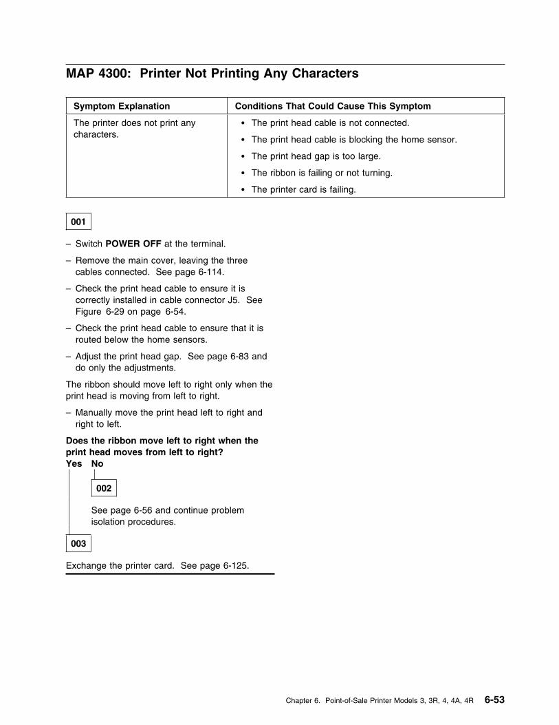
MAP 4300: Printer Not Printing Any Characters
Symptom Explanation Conditions That Could Cause This Symptom
The printer does not print anycharacters.
� The print head cable is not connected.
� The print head cable is blocking the home sensor.
� The print head gap is too large.
� The ribbon is failing or not turning.
� The printer card is failing.
001
– Switch POWER OFF at the terminal.
– Remove the main cover, leaving the threecables connected. See page 6-114.
– Check the print head cable to ensure it iscorrectly installed in cable connector J5. SeeFigure 6-29 on page 6-54.
– Check the print head cable to ensure that it isrouted below the home sensors.
– Adjust the print head gap. See page 6-83 anddo only the adjustments.
The ribbon should move left to right only when theprint head is moving from left to right.
– Manually move the print head left to right andright to left.
Does the ribbon move left to right when theprint head moves from left to right?Yes No
002
See page 6-56 and continue problemisolation procedures.
003
Exchange the printer card. See page 6-125.
Chapter 6. Point-of-Sale Printer Models 3, 3R, 4, 4A, 4R 6-53
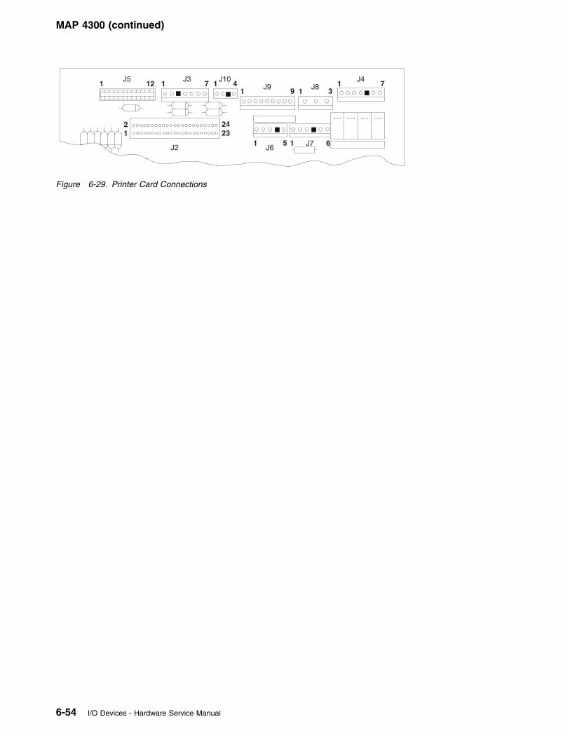
MAP 4300 (continued)
1J5
12 1J3
7
21
2423
J10
1J9 9 1
1 5 1J6
J7 6
31
J47J81 4
J2
Figure 6-29. Printer Card Connections
6-54 I/O Devices - Hardware Service Manual
MAP 4310: Ribbon Damaged by Printer
Symptom Explanation Conditions That Could Cause This Symptom
The ribbon is being damaged bythe printer.
� The printer ribbon cartridge is not turning.
� The print head gap is not set correctly.
� The print head is failing.
001
– Switch POWER OFF at the terminal.
The ribbon should move left to right only when theprint head is moving from left to right.
– Manually move the print head left to right andright to left.
Does the ribbon move left to right when theprint head moves from left to right?Yes No
002
See page 6-56 and continue problemisolation procedures.
003
– Check the print head gap. See page 6-83.
Is the print head gap set correctly?Yes No
004
– Adjust the print head gap. See page6-83.
005
Exchange the print head. See page 6-83.
Chapter 6. Point-of-Sale Printer Models 3, 3R, 4, 4A, 4R 6-55
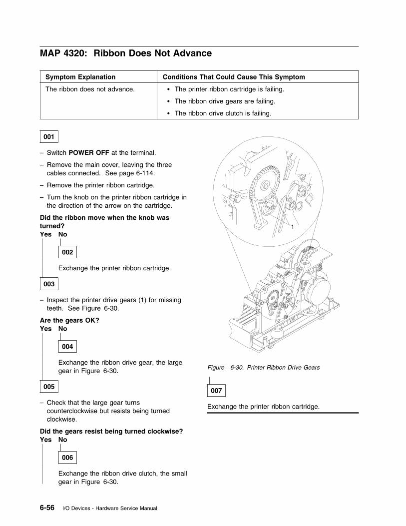
MAP 4320: Ribbon Does Not Advance
Symptom Explanation Conditions That Could Cause This Symptom
The ribbon does not advance. � The printer ribbon cartridge is failing.
� The ribbon drive gears are failing.
� The ribbon drive clutch is failing.
001
– Switch POWER OFF at the terminal.
– Remove the main cover, leaving the threecables connected. See page 6-114.
– Remove the printer ribbon cartridge.
– Turn the knob on the printer ribbon cartridge inthe direction of the arrow on the cartridge.
Did the ribbon move when the knob wasturned?Yes No
002
Exchange the printer ribbon cartridge.
003
– Inspect the printer drive gears (1) for missingteeth. See Figure 6-30.
Are the gears OK?Yes No
004
Exchange the ribbon drive gear, the largegear in Figure 6-30.
005
– Check that the large gear turnscounterclockwise but resists being turnedclockwise.
Did the gears resist being turned clockwise?Yes No
006
Exchange the ribbon drive clutch, the smallgear in Figure 6-30.
1
Figure 6-30. Printer Ribbon Drive Gears
007
Exchange the printer ribbon cartridge.
6-56 I/O Devices - Hardware Service Manual
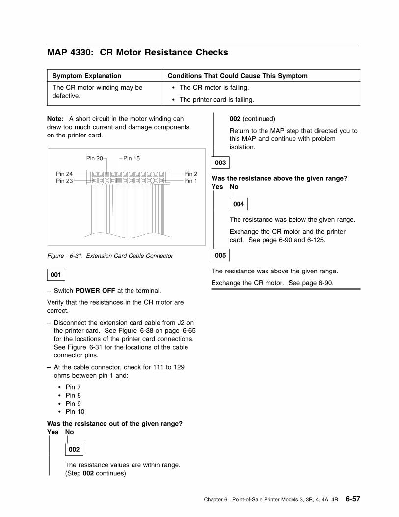
MAP 4330: CR Motor Resistance Checks
Symptom Explanation Conditions That Could Cause This Symptom
The CR motor winding may bedefective.
� The CR motor is failing.
� The printer card is failing.
Note: A short circuit in the motor winding candraw too much current and damage componentson the printer card.
Pin 2Pin 1
Pin 24Pin 23
Pin 20 Pin 15
Figure 6-31. Extension Card Cable Connector
001
– Switch POWER OFF at the terminal.
Verify that the resistances in the CR motor arecorrect.
– Disconnect the extension card cable from J2 onthe printer card. See Figure 6-38 on page 6-65for the locations of the printer card connections.See Figure 6-31 for the locations of the cableconnector pins.
– At the cable connector, check for 111 to 129ohms between pin 1 and:
� Pin 7 � Pin 8 � Pin 9 � Pin 10
Was the resistance out of the given range?Yes No
002
The resistance values are within range.(Step 002 continues)
002 (continued)
Return to the MAP step that directed you tothis MAP and continue with problemisolation.
003
Was the resistance above the given range?Yes No
004
The resistance was below the given range.
Exchange the CR motor and the printercard. See page 6-90 and 6-125.
005
The resistance was above the given range.
Exchange the CR motor. See page 6-90.
Chapter 6. Point-of-Sale Printer Models 3, 3R, 4, 4A, 4R 6-57

MAP 4340: Paper Cutter Motor Resistance Checks
Symptom Explanation Conditions That Could Cause This Symptom
The paper cutter motor may bedefective.
� The paper cutter motor is failing.
� The printer card is failing.
Note: A short circuit in the motor winding candraw too much current and damage componentson the printer card.
Pin 2Pin 1
Pin 24Pin 23
Pin 20 Pin 15
Figure 6-32. Extension Card Cable Connector
001
– Switch POWER OFF at the terminal.
Verify that the resistances in the paper cuttermotor at the CR station are correct.
– Disconnect the extension card cable from J2 onthe printer card. See Figure 6-38 on page 6-65for the locations of the printer card connections.See Figure 6-32 for the locations of the cableconnector pins.
– At the cable connector, check for 111 to 129ohms between pin 2 and:
� Pin 3 � Pin 4 � Pin 5 � Pin 6
Was the resistance out of the given range?Yes No
002
The resistance values are within range.(Step 002 continues)
002 (continued)
Return to the MAP step that directed you tothis MAP and continue with problemisolation.
003
Was the resistance above the given range?Yes No
004
The resistance was below the given range.
Exchange the paper cutter motor and theprinter card. See page 6-87 and 6-125.
005
The resistance was above the given range.
Exchange the paper cutter motor. See page 6-87.
6-58 I/O Devices - Hardware Service Manual
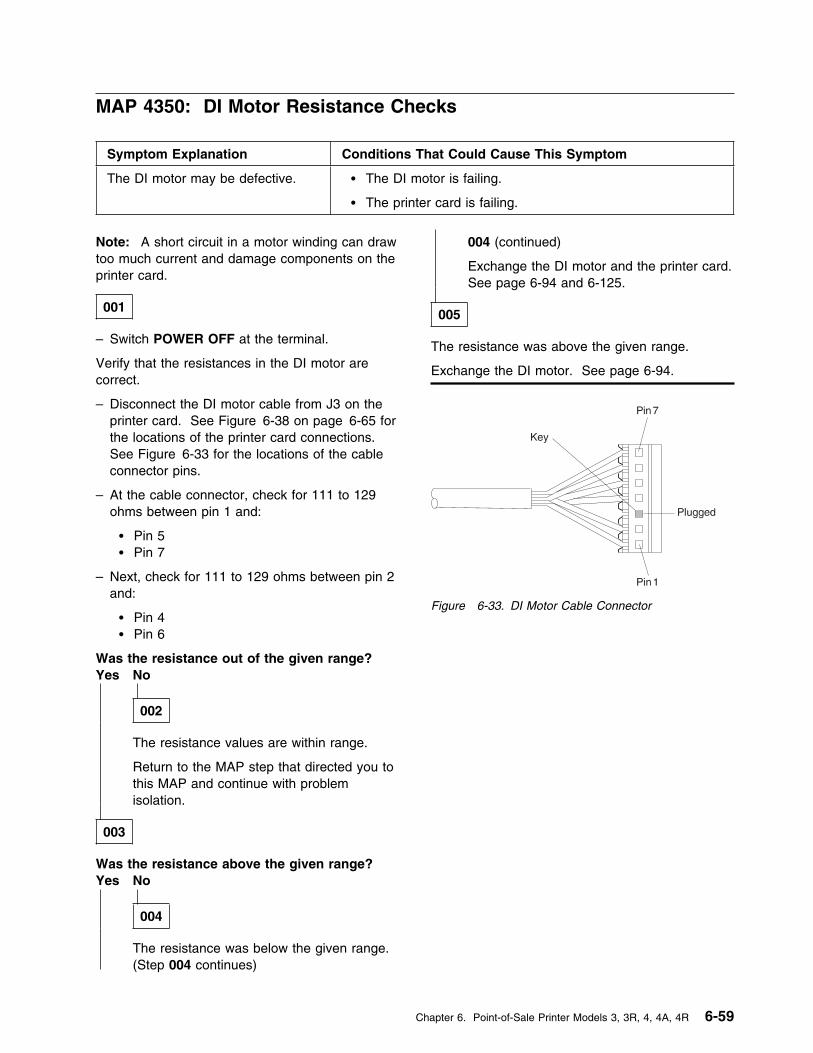
MAP 4350: DI Motor Resistance Checks
Symptom Explanation Conditions That Could Cause This Symptom
The DI motor may be defective. � The DI motor is failing.
� The printer card is failing.
Note: A short circuit in a motor winding can drawtoo much current and damage components on theprinter card.
001
– Switch POWER OFF at the terminal.
Verify that the resistances in the DI motor arecorrect.
– Disconnect the DI motor cable from J3 on theprinter card. See Figure 6-38 on page 6-65 forthe locations of the printer card connections.See Figure 6-33 for the locations of the cableconnector pins.
– At the cable connector, check for 111 to 129ohms between pin 1 and:
� Pin 5 � Pin 7
– Next, check for 111 to 129 ohms between pin 2and:
� Pin 4 � Pin 6
Was the resistance out of the given range?Yes No
002
The resistance values are within range.
Return to the MAP step that directed you tothis MAP and continue with problemisolation.
003
Was the resistance above the given range?Yes No
004
The resistance was below the given range.(Step 004 continues)
004 (continued)
Exchange the DI motor and the printer card.See page 6-94 and 6-125.
005
The resistance was above the given range.
Exchange the DI motor. See page 6-94.
Figure 6-33. DI Motor Cable Connector
Chapter 6. Point-of-Sale Printer Models 3, 3R, 4, 4A, 4R 6-59
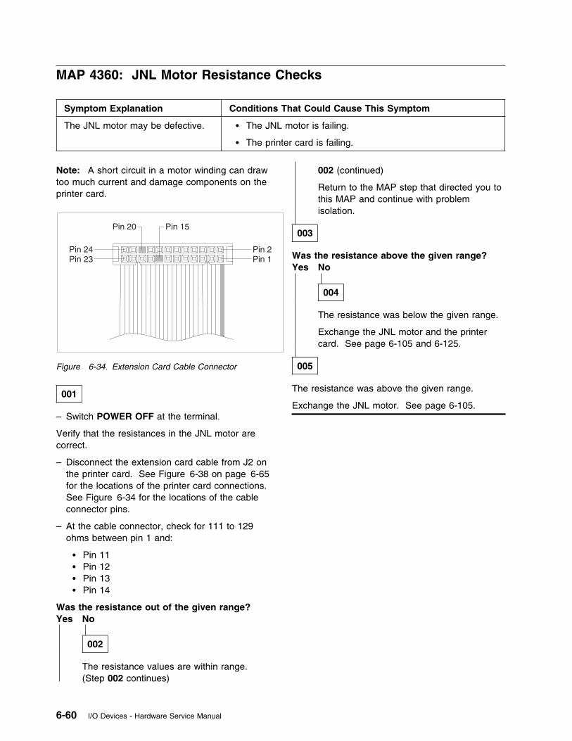
MAP 4360: JNL Motor Resistance Checks
Symptom Explanation Conditions That Could Cause This Symptom
The JNL motor may be defective. � The JNL motor is failing.
� The printer card is failing.
Note: A short circuit in a motor winding can drawtoo much current and damage components on theprinter card.
Pin 2Pin 1
Pin 24Pin 23
Pin 20 Pin 15
Figure 6-34. Extension Card Cable Connector
001
– Switch POWER OFF at the terminal.
Verify that the resistances in the JNL motor arecorrect.
– Disconnect the extension card cable from J2 onthe printer card. See Figure 6-38 on page 6-65for the locations of the printer card connections.See Figure 6-34 for the locations of the cableconnector pins.
– At the cable connector, check for 111 to 129ohms between pin 1 and:
� Pin 11 � Pin 12 � Pin 13 � Pin 14
Was the resistance out of the given range?Yes No
002
The resistance values are within range.(Step 002 continues)
002 (continued)
Return to the MAP step that directed you tothis MAP and continue with problemisolation.
003
Was the resistance above the given range?Yes No
004
The resistance was below the given range.
Exchange the JNL motor and the printercard. See page 6-105 and 6-125.
005
The resistance was above the given range.
Exchange the JNL motor. See page 6-105.
6-60 I/O Devices - Hardware Service Manual
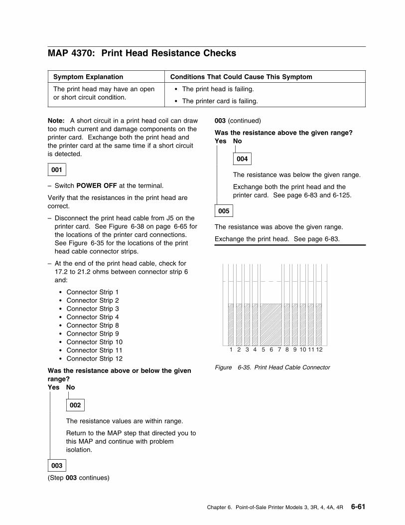
MAP 4370: Print Head Resistance Checks
Symptom Explanation Conditions That Could Cause This Symptom
The print head may have an openor short circuit condition.
� The print head is failing.
� The printer card is failing.
Note: A short circuit in a print head coil can drawtoo much current and damage components on theprinter card. Exchange both the print head andthe printer card at the same time if a short circuitis detected.
001
– Switch POWER OFF at the terminal.
Verify that the resistances in the print head arecorrect.
– Disconnect the print head cable from J5 on theprinter card. See Figure 6-38 on page 6-65 forthe locations of the printer card connections.See Figure 6-35 for the locations of the printhead cable connector strips.
– At the end of the print head cable, check for17.2 to 21.2 ohms between connector strip 6and:
� Connector Strip 1� Connector Strip 2� Connector Strip 3� Connector Strip 4� Connector Strip 8� Connector Strip 9� Connector Strip 10� Connector Strip 11� Connector Strip 12
Was the resistance above or below the givenrange?Yes No
002
The resistance values are within range.
Return to the MAP step that directed you tothis MAP and continue with problemisolation.
003
(Step 003 continues)
003 (continued)
Was the resistance above the given range?Yes No
004
The resistance was below the given range.
Exchange both the print head and theprinter card. See page 6-83 and 6-125.
005
The resistance was above the given range.
Exchange the print head. See page 6-83.
1 2 3 4 5 76 8 9 10 11 12
Figure 6-35. Print Head Cable Connector
Chapter 6. Point-of-Sale Printer Models 3, 3R, 4, 4A, 4R 6-61
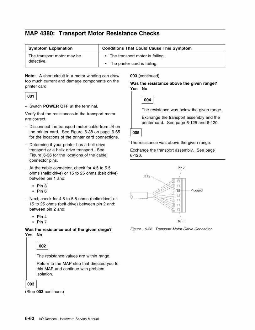
MAP 4380: Transport Motor Resistance Checks
Symptom Explanation Conditions That Could Cause This Symptom
The transport motor may bedefective.
� The transport motor is failing.
� The printer card is failing.
Note: A short circuit in a motor winding can drawtoo much current and damage components on theprinter card.
001
– Switch POWER OFF at the terminal.
Verify that the resistances in the transport motorare correct.
– Disconnect the transport motor cable from J4 onthe printer card. See Figure 6-38 on page 6-65for the locations of the printer card connections.
– Determine if your printer has a belt drivetransport or a helix drive transport. SeeFigure 6-36 for the locations of the cableconnector pins.
– At the cable connector, check for 4.5 to 5.5ohms (helix drive) or 15 to 25 ohms (belt drive)between pin 1 and:
� Pin 3 � Pin 6
– Next, check for 4.5 to 5.5 ohms (helix drive) or15 to 25 ohms (belt drive) between pin 2 and:between pin 2 and:
� Pin 4 � Pin 7
Was the resistance out of the given range?Yes No
002
The resistance values are within range.
Return to the MAP step that directed you tothis MAP and continue with problemisolation.
003
(Step 003 continues)
003 (continued)
Was the resistance above the given range?Yes No
004
The resistance was below the given range.
Exchange the transport assembly and theprinter card. See page 6-125 and 6-120.
005
The resistance was above the given range.
Exchange the transport assembly. See page6-120.
Figure 6-36. Transport Motor Cable Connector
6-62 I/O Devices - Hardware Service Manual
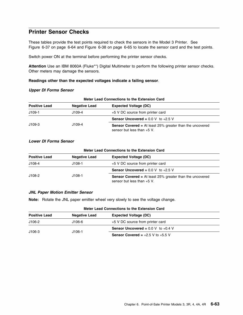
Printer Sensor Checks
These tables provide the test points required to check the sensors in the Model 3 Printer. SeeFigure 6-37 on page 6-64 and Figure 6-38 on page 6-65 to locate the sensor card and the test points.
Switch power ON at the terminal before performing the printer sensor checks.
Attention Use an IBM 8060A (Fluke**) Digital Multimeter to perform the following printer sensor checks.Other meters may damage the sensors.
Readings other than the expected voltages indicate a failing sensor.
Upper DI Forms Sensor
Meter Lead Connections to the Extension Card
Positive Lead Negative Lead Expected Voltage (DC)
J109-1 J109-4 +5 V DC source from printer card
J109-3 J109-4
Sensor Uncovered = 0.0 V to +2.5 V
Sensor Covered = At least 25% greater than the uncoveredsensor but less than +5 V.
Lower DI Forms Sensor
Meter Lead Connections to the Extension Card
Positive Lead Negative Lead Expected Voltage (DC)
J108-4 J108-1 +5 V DC source from printer card
J108-2 J108-1
Sensor Uncovered = 0.0 V to +2.5 V
Sensor Covered = At least 25% greater than the uncoveredsensor but less than +5 V.
JNL Paper Motion Emitter Sensor
Note: Rotate the JNL paper emitter wheel very slowly to see the voltage change.
Meter Lead Connections to the Extension Card
Positive Lead Negative Lead Expected Voltage (DC)
J106-2 J106-6 +5 V DC source from printer card
J106-3 J106-1Sensor Uncovered = 0.0 V to +0.4 V
Sensor Covered = +2.5 V to +5.5 V
Chapter 6. Point-of-Sale Printer Models 3, 3R, 4, 4A, 4R 6-63
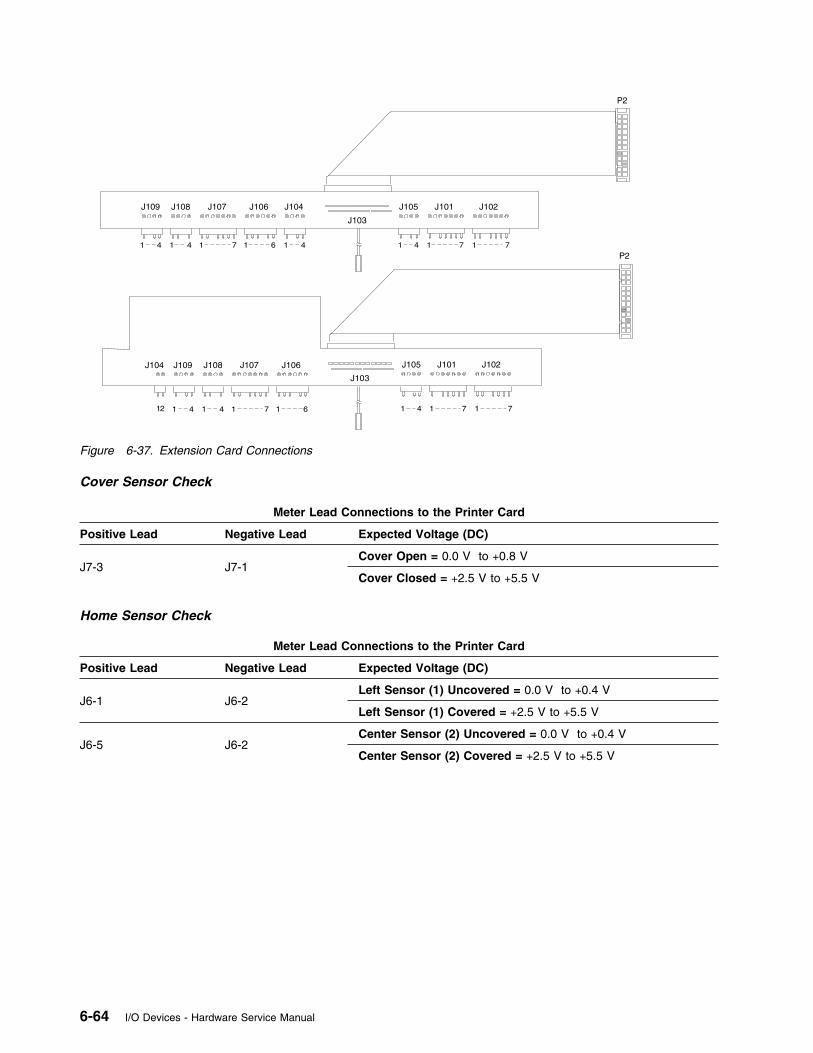
J102J101J105J104 J106J107J108J109
J103
1 141 6 1 14 141 7 77
P2
J102J101J105J104J106J107J108J109
J103
1 1 4141 6 1 14 141 7 77
P2
12
Figure 6-37. Extension Card Connections
Cover Sensor Check
Meter Lead Connections to the Printer Card
Positive Lead Negative Lead Expected Voltage (DC)
J7-3 J7-1Cover Open = 0.0 V to +0.8 V
Cover Closed = +2.5 V to +5.5 V
Home Sensor Check
Meter Lead Connections to the Printer Card
Positive Lead Negative Lead Expected Voltage (DC)
J6-1 J6-2Left Sensor (1) Uncovered = 0.0 V to +0.4 V
Left Sensor (1) Covered = +2.5 V to +5.5 V
J6-5 J6-2Center Sensor (2) Uncovered = 0.0 V to +0.4 V
Center Sensor (2) Covered = +2.5 V to +5.5 V
6-64 I/O Devices - Hardware Service Manual
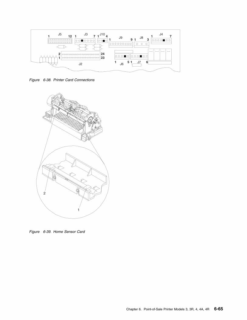
1J5
12 1J3
7
21
2423
J10
1J9 9 1
1 5 1J6
J7 6
31
J47J81 4
J2
Figure 6-38. Printer Card Connections
2
1
Figure 6-39. Home Sensor Card
Chapter 6. Point-of-Sale Printer Models 3, 3R, 4, 4A, 4R 6-65
Sensor Cleaning Procedures
Clean the sensors any time that the printer is being serviced.
DI Sensors
1 Open the printer access cover.
2 Remove the printer ribbon cartridge.
3 Remove the debris from around both of the sensors.
4 Clean both the lower and upper DI sensors. See Figure 6-67 on page 6-98 or Figure 6-69 onpage 6-99 for an illustration of the DI sensors.
Home Sensor Card
1 Open the printer access cover.
2 Remove the printer ribbon cartridge.
3 Push the print head all the way to the right.
4 Use a cotton swab dipped in isopropyl alcohol to clean the two home sensors. See Figure 6-39 onpage 6-65 for an illustration of the home sensors.
JNL Paper Sensor
1 Open the printer access cover.
2 Open the JNL cover.
3 Remove the JNL spool and the JNL paper.
4 Toggle the JNL roller forward by pulling the JNL lever toward you.
5 Clean both the sensor and the emitter wheel. See Figure 6-76 on page 6-107 for an illustration ofthe sensor and of the emitter wheel.
6-66 I/O Devices - Hardware Service Manual
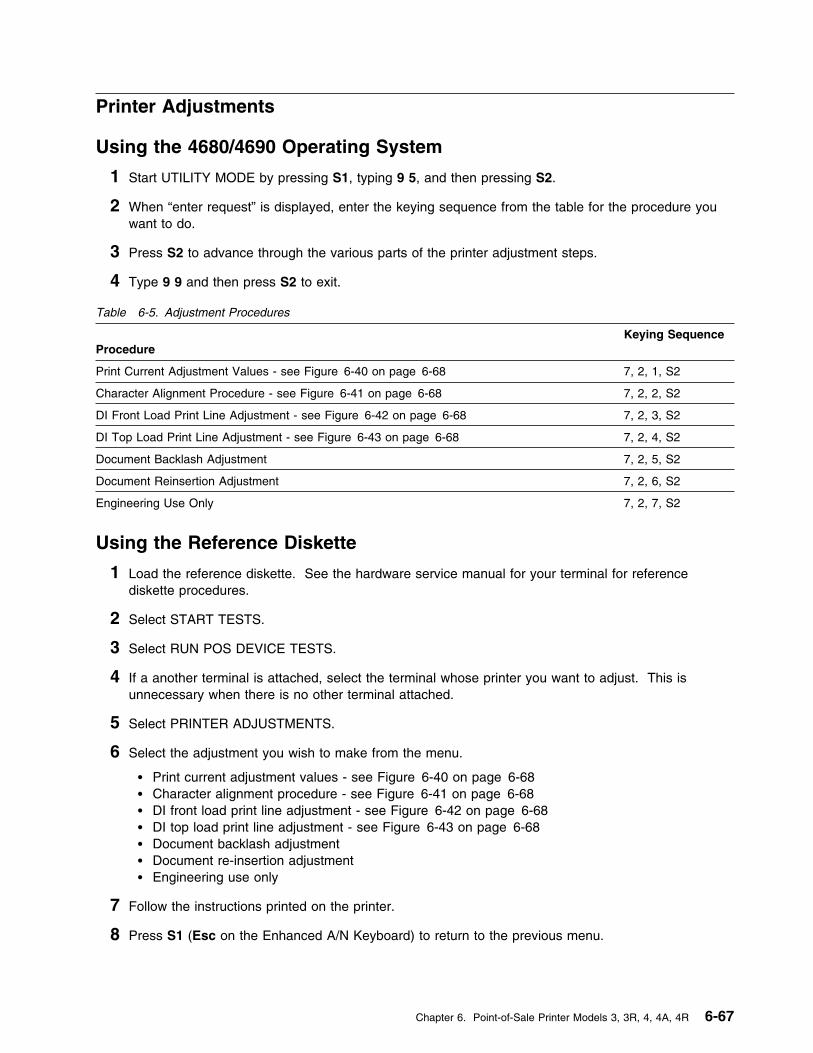
Printer Adjustments
Using the 4680/4690 Operating System
1 Start UTILITY MODE by pressing S1, typing 9 5, and then pressing S2.
2 When “enter request” is displayed, enter the keying sequence from the table for the procedure youwant to do.
3 Press S2 to advance through the various parts of the printer adjustment steps.
4 Type 9 9 and then press S2 to exit.
Table 6-5. Adjustment Procedures
Procedure
Keying Sequence
Print Current Adjustment Values - see Figure 6-40 on page 6-68 7, 2, 1, S2
Character Alignment Procedure - see Figure 6-41 on page 6-68 7, 2, 2, S2
DI Front Load Print Line Adjustment - see Figure 6-42 on page 6-68 7, 2, 3, S2
DI Top Load Print Line Adjustment - see Figure 6-43 on page 6-68 7, 2, 4, S2
Document Backlash Adjustment 7, 2, 5, S2
Document Reinsertion Adjustment 7, 2, 6, S2
Engineering Use Only 7, 2, 7, S2
Using the Reference Diskette
1 Load the reference diskette. See the hardware service manual for your terminal for referencediskette procedures.
2 Select START TESTS.
3 Select RUN POS DEVICE TESTS.
4 If a another terminal is attached, select the terminal whose printer you want to adjust. This isunnecessary when there is no other terminal attached.
5 Select PRINTER ADJUSTMENTS.
6 Select the adjustment you wish to make from the menu.
� Print current adjustment values - see Figure 6-40 on page 6-68 � Character alignment procedure - see Figure 6-41 on page 6-68 � DI front load print line adjustment - see Figure 6-42 on page 6-68 � DI top load print line adjustment - see Figure 6-43 on page 6-68 � Document backlash adjustment� Document re-insertion adjustment� Engineering use only
7 Follow the instructions printed on the printer.
8 Press S1 (Esc on the Enhanced A/N Keyboard) to return to the previous menu.
Chapter 6. Point-of-Sale Printer Models 3, 3R, 4, 4A, 4R 6-67
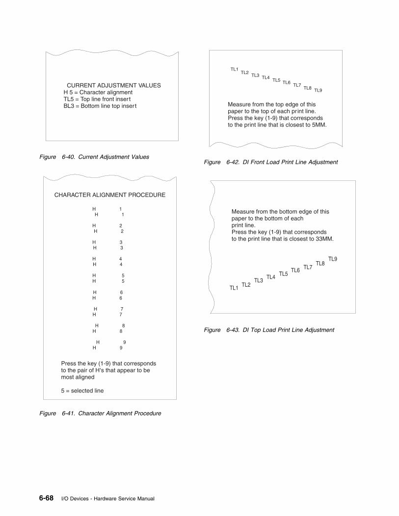
CURRENT ADJUSTMENT VALUESH 5 = Character alignmentTL5 = Top line front insertBL3 = Bottom line top insert
Figure 6-40. Current Adjustment Values
Press the key (1-9) that correspondsto the pair of H's that appear to bemost aligned
5 = selected line
CHARACTER ALIGNMENT PROCEDURE
Figure 6-41. Character Alignment Procedure
Measure from the top edge of thispaper to the top of each pr int line.Press the key (1-9) that correspondsto the print line that is closest to 5MM.
TL1
TL4
TL7
TL2
TL5
TL8
TL3
TL6
TL9
Figure 6-42. DI Front Load Print Line Adjustment
Measure from the bottom edge of thispaper to the bottom of eachprint line.Press the key (1-9) that correspondsto the print line that is closest to 33MM.
TL1
TL4
TL7
TL2
TL5
TL8
TL3
TL6
TL9
Figure 6-43. DI Top Load Print Line Adjustment
6-68 I/O Devices - Hardware Service Manual
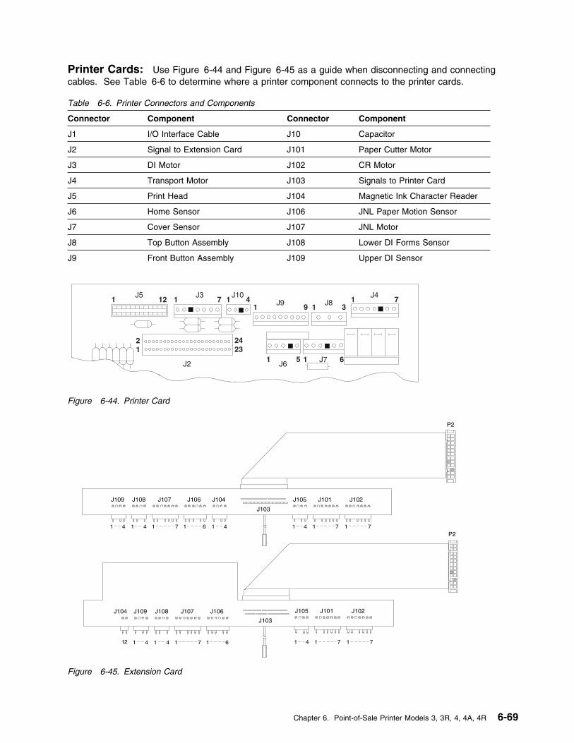
Printer Cards: Use Figure 6-44 and Figure 6-45 as a guide when disconnecting and connectingcables. See Table 6-6 to determine where a printer component connects to the printer cards.
1J5
12 1J3
7
21
2423
J10
1J9 9 1
1 5 1J6
J7 6
31
J47J81 4
J2
Figure 6-44. Printer Card
Table 6-6. Printer Connectors and Components
Connector Component Connector Component
J1 I/O Interface Cable J10 Capacitor
J2 Signal to Extension Card J101 Paper Cutter Motor
J3 DI Motor J102 CR Motor
J4 Transport Motor J103 Signals to Printer Card
J5 Print Head J104 Magnetic Ink Character Reader
J6 Home Sensor J106 JNL Paper Motion Sensor
J7 Cover Sensor J107 JNL Motor
J8 Top Button Assembly J108 Lower DI Forms Sensor
J9 Front Button Assembly J109 Upper DI Sensor
J102J101J105J104 J106J107J108J109
J103
1 141 6 1 14 141 7 77
P2
J102J101J105J104J106J107J108J109
J103
1 1 4141 6 1 14 141 7 77
P2
12
Figure 6-45. Extension Card
Chapter 6. Point-of-Sale Printer Models 3, 3R, 4, 4A, 4R 6-69

Removal and Replacement Procedures
Before Beginning
1 After exchanging any printer FRU, run the Stand-Alone Printer Test to ensure that the failure iscorrected. See page 6-4.
2 See Table 6-7 on page 6-72 for information about FRUs not listed here.
Removing and Replacing the AccessCover . . . . . . . . . . . . . . . . . . . 6-73
Removing the Access Cover . . . . . 6-73Replacing the Access Cover . . . . . 6-73
Removing and Replacing the Front ButtonAssembly . . . . . . . . . . . . . . . . . 6-74
Removing the Front Buttons . . . . . 6-74Replacing the Front Buttons . . . . . 6-74
Removing and Replacing the AcousticFlap . . . . . . . . . . . . . . . . . . . . 6-75
Removing the Acoustic Flap . . . . . 6-75Replacing the Acoustic Flap . . . . . 6-75
Removing and Replacing the Upper DIGuide . . . . . . . . . . . . . . . . . . . 6-77
Removing the Upper DI Guide . . . . 6-77Replacing the Upper DI Guide . . . . 6-77
Removing and Replacing the Base . . . 6-78Removing the Base . . . . . . . . . . 6-78Replacing the Base . . . . . . . . . . 6-78
Removing and Replacing the Top ButtonAssembly (Model 3) . . . . . . . . . . . 6-80
Removing the Top Buttons . . . . . . 6-80Replacing the Top Button Assembly . 6-80
Removing and Replacing the Button andCover Sensor Assembly (Model 4) . . 6-81
Removing the Top Buttons and CoverSensor . . . . . . . . . . . . . . . . . 6-81
Replacing the Top Button Assembly . 6-81Removing and Replacing the Cover
Sensor (Model 3 only) . . . . . . . . . . 6-82Removing the Cover Sensor . . . . . 6-82Replacing the Cover Sensor . . . . . 6-82
Removing and Replacing the Print Head 6-83Removing the Print Head . . . . . . . 6-83Replacing the Print Head . . . . . . . 6-83
Removing and Replacing the Capacitor 6-86Removing the Capacitor . . . . . . . . 6-86Replacing the Capacitor . . . . . . . . 6-86
Removing and Replacing the PaperCutter . . . . . . . . . . . . . . . . . . . 6-87
Removing the Paper Cutter . . . . . . 6-87Replacing the Paper Cutter . . . . . . 6-87
Removing and Replacing the CR Motor 6-88Removing the CR Motor . . . . . . . 6-88Replacing the CR Motor . . . . . . . . 6-88
Removing and Replacing the CR MotorGear Assembly . . . . . . . . . . . . . . 6-90
Removing the CR Motor GearAssembly . . . . . . . . . . . . . . . 6-90
Replacing the CR Motor GearAssembly . . . . . . . . . . . . . . . 6-90
Removing and Replacing the CR RollerAssembly . . . . . . . . . . . . . . . . . 6-92
Removing the CR Roller Assembly . 6-92Replacing the CR Roller Assembly . 6-92
Removing and Replacing the DI Motor . 6-94Removing the DI Motor . . . . . . . . 6-94Replacing the DI Motor . . . . . . . . 6-94
Removing and Replacing the DI Gears 6-96Removing the DI gears . . . . . . . . 6-96Replacing the DI Gears . . . . . . . . 6-96
Removing and Replacing the Lower DISensor . . . . . . . . . . . . . . . . . . 6-97
Removing the Lower DI Forms Sensor 6-97Replacing the Lower DI Forms Sensor 6-97
Removing and Replacing the Upper DISensor . . . . . . . . . . . . . . . . . . 6-99
Removing the Upper DI Sensor . . . 6-99Replacing the Upper DI Sensor . . . 6-99
Removing and Replacing the MagneticInk Character Reader (MICR) . . . . 6-100
Removing the Magnetic Ink CharacterReader . . . . . . . . . . . . . . . . 6-100
Replacing the Magnetic Ink CharacterReader . . . . . . . . . . . . . . . . 6-100
Removing and Replacing the MagneticInk Character Reader Pressure Pad 6-101
Removing the Magnetic Ink CharacterReader Pressure Pad . . . . . . . 6-101
Replacing the Magnetic Ink CharacterReader Pressure Pad . . . . . . . 6-101
Removing and Replacing the JNL Cover 6-102Removing the JNL Cover . . . . . . 6-102Replacing the JNL Cover . . . . . . 6-102
Removing and Replacing the JNL Lock 6-103Removing the JNL Lock . . . . . . . 6-103Replacing the JNL lock . . . . . . . 6-103
Removing and Replacing the JNLTakeup Clutch, Gears, and Pawl . . 6-104
6-70 I/O Devices - Hardware Service Manual
Removing the Takeup Clutch, Gears,and Pawl . . . . . . . . . . . . . . . 6-104
Replacing the Takeup clutch, Gears,and Pawl . . . . . . . . . . . . . . . 6-104
Removing and Replacing the JNL Motor 6-105Removing the JNL Motor . . . . . . 6-105Replacing the JNL Motor . . . . . . 6-105
Removing and Replacing the JNL PaperMotion Sensor . . . . . . . . . . . . . 6-106
Removing the JNL Paper MotionSensor . . . . . . . . . . . . . . . . 6-106
Replacing the JNL Paper MotionSensor . . . . . . . . . . . . . . . . 6-106
Removing and Replacing the JNL RollerAssembly and Frame . . . . . . . . . 6-108
Removing the JNL Assembly . . . . 6-108Replacing the JNL Assembly . . . . 6-108
Removing and Replacing the JNLSupport Post . . . . . . . . . . . . . . 6-110
Removing the JNL Support Post . . 6-110Replacing the JNL Support Post . . 6-110
Removing and Replacing the JNL Spool 6-112Removing the JNL Spool . . . . . . 6-112Replacing the JNL Spool . . . . . . 6-112
Removing and Replacing the PaperRollers . . . . . . . . . . . . . . . . . . 6-113
Removing the Paper Rollers . . . . 6-113Replacing the Paper Rollers . . . . 6-113
Removing and Replacing the MainCover . . . . . . . . . . . . . . . . . . 6-114
Removing the Main Cover . . . . . 6-114Replacing the Main Cover . . . . . 6-114
Removing and Replacing the PlatenAssembly . . . . . . . . . . . . . . . . 6-116
Removing the Platen Assembly . . 6-116Replacing the Platen Assembly . . 6-116
Removing and Replacing the HomeSensor Card . . . . . . . . . . . . . . 6-118
Removing the Home Sensor Card . 6-118Replacing the Home Sensor Card . 6-118
Removing and Replacing the TransportAssembly . . . . . . . . . . . . . . . . 6-120
Removing and Replacing the Helix DriveTransport Assembly . . . . . . . . . . 6-120
Removing the Transport Assembly 6-120Replacing the Transport Assembly 6-120
Converting From Helix to Belt DriveTransport Assembly . . . . . . . . . . 6-123
Removing and Replacing the Belt DriveTransport Assembly . . . . . . . . . . 6-123
Removing the Transport Assembly 6-123Replacing the Transport Assembly 6-123
Removing and Replacing the PrinterCard . . . . . . . . . . . . . . . . . . . 6-125
Removing the Printer Card . . . . . 6-125Replacing the Printer Card . . . . . 6-125
Removing and Replacing the ExtensionCard . . . . . . . . . . . . . . . . . . . 6-127
Removing the Extension Card . . . 6-127Replacing the Extension Card . . . 6-127
Chapter 6. Point-of-Sale Printer Models 3, 3R, 4, 4A, 4R 6-71

There are no removal and replacement procedures for the following FRUs. Use the following table to findinformation when it is necessary to exchange the items listed.
You need to use special tools to perform some removal and replacement procedures. See Table 6-8 todetermine the tool part numbers.
Table 6-7. Where To Go For Information
FRU See Page
Paper Cutter Cover 6-87
Ribbon Drive Gear 6-122
Anti-Chatter Clip 6-122
Ribbon Clutch 6-122
Front Carrier Shaft 6-122
CR Feed Roll Gear andBearing
6-90
Carrier Bushing 6-122
JNL Ledge 6-109
MICR Magnet 6-98
Home Sensor Cable 6-118
Print Head shield 6-84
Table 6-8. Special Tools
Tool Part Number
Number 2 Phillips Bit 16F1664
Print Head Gap Setter 93F0419
Torque Screwdriver 16F1661
T10 Torx bit 16F1617 or 39F8407 from kit P/N 39F8407
6-72 I/O Devices - Hardware Service Manual
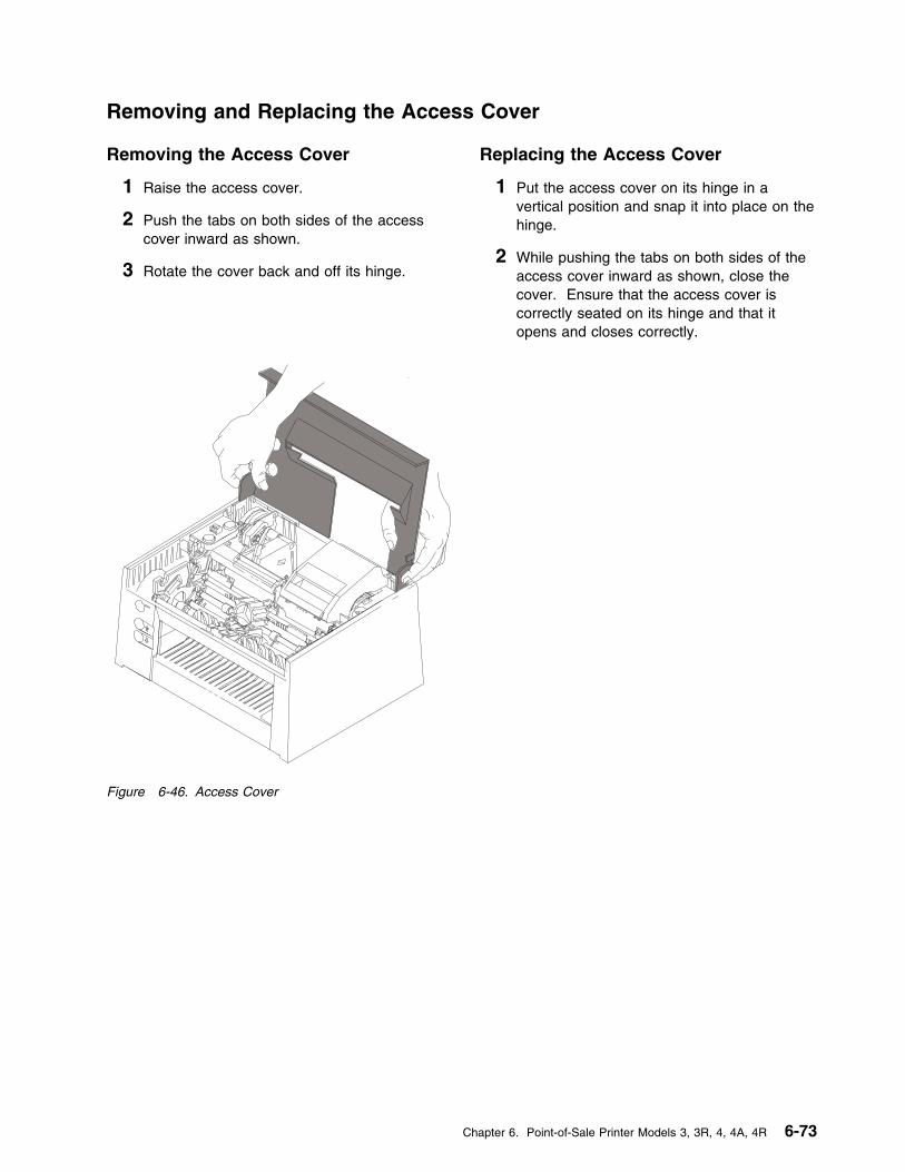
Removing and Replacing the Access Cover
Removing the Access Cover
1 Raise the access cover.
2 Push the tabs on both sides of the accesscover inward as shown.
3 Rotate the cover back and off its hinge.
Replacing the Access Cover
1 Put the access cover on its hinge in avertical position and snap it into place on thehinge.
2 While pushing the tabs on both sides of theaccess cover inward as shown, close thecover. Ensure that the access cover iscorrectly seated on its hinge and that itopens and closes correctly.
Figure 6-46. Access Cover
Chapter 6. Point-of-Sale Printer Models 3, 3R, 4, 4A, 4R 6-73
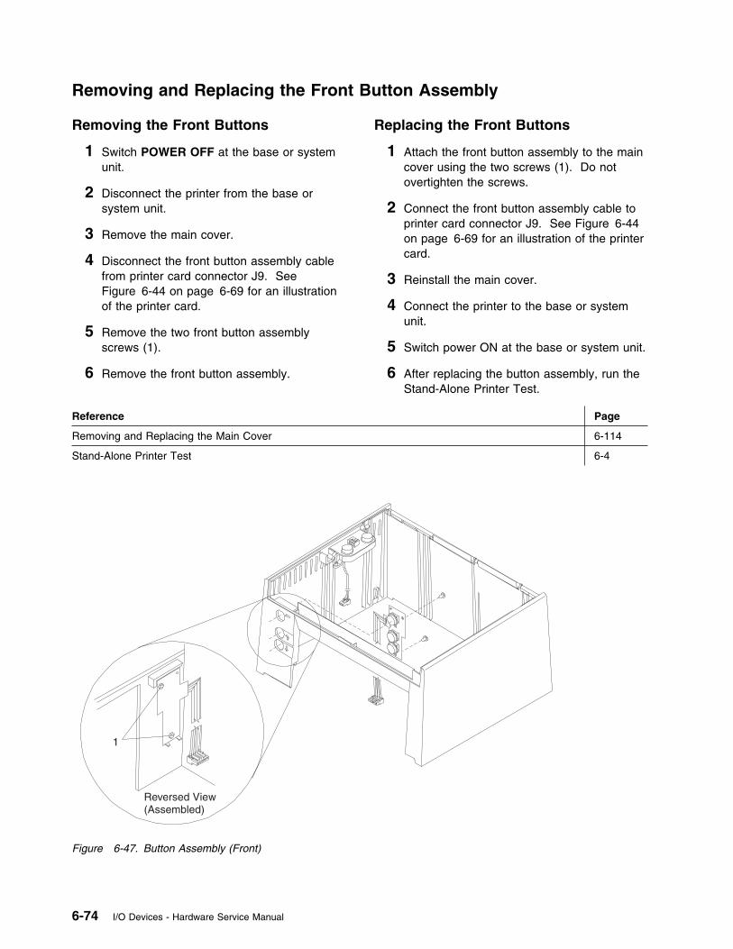
Removing and Replacing the Front Button Assembly
Removing the Front Buttons
1 Switch POWER OFF at the base or systemunit.
2 Disconnect the printer from the base orsystem unit.
3 Remove the main cover.
4 Disconnect the front button assembly cablefrom printer card connector J9. SeeFigure 6-44 on page 6-69 for an illustrationof the printer card.
5 Remove the two front button assemblyscrews (1).
6 Remove the front button assembly.
Replacing the Front Buttons
1 Attach the front button assembly to the maincover using the two screws (1). Do notovertighten the screws.
2 Connect the front button assembly cable toprinter card connector J9. See Figure 6-44on page 6-69 for an illustration of the printercard.
3 Reinstall the main cover.
4 Connect the printer to the base or systemunit.
5 Switch power ON at the base or system unit.
6 After replacing the button assembly, run theStand-Alone Printer Test.
Reference Page
Removing and Replacing the Main Cover 6-114
Stand-Alone Printer Test 6-4
1
Reversed View(Assembled)
Figure 6-47. Button Assembly (Front)
6-74 I/O Devices - Hardware Service Manual
Removing and Replacing the Acoustic Flap
Removing the Acoustic Flap NOTE: TheAcoustic Flap reduces printer noise and holds thefront-ejected forms in the printer. The new flaphas a polyester film that makes it moredamage-resistant, as well as making it easier toinsert a form. The alignment of the flap'sadhesive edges to the cover is very important forforms handling. A correctly installed flap does notallow the forms to catch or crumple.
1 Remove the main cover.
2 Place the printer on its back so the front ofthe printer is facing upward.
3 Remove the damaged flap and all theremaining foam material. Also remove anydirt, debris, and old adhesive from the area.
Tips:
� See Figure 6-48 on page 6-76.� The vinyl foam material tears easily.� Use a screwdriver to pry the old flap
loose then pull up to remove.� Use a screwdriver to scrape off any
remaining foam material.� Use needlenose pliers to remove any
debris. Do not use alcohol.
Replacing the Acoustic Flap
1 Lift up 25.4mm (1 inch) of both adhesivestrips on one end of the flap. Fold bothadhesive strips outward. Later, you will useneedlenose pliers to remove the remainderof the strip, after the flap is correctlypositioned. See Figure 6-48 on page 6-76.
2 Fold the flap in a U-shape with the shinyside out so that both adhesive edges comein contact with the cover. See Figure 6-48on page 6-76.
3 Align the flap flush with the left side of thecover.
4 Place the flap against the square corner (1)of the inner locating rib on the cover. Alignthe edge of the flap along the rib.
5 Holding the flap in position with your fingers,slowly remove the adhesive strip using theneedlenose pliers. Press hard on theadhesive after the strip is removed becausethe adhesive is pressure activated.
6 Place the shiny edge of the flap on thesquare corner (2) of the outer locating rib.Align the edge of the flap along the rib.
7 Holding the flap in position with your fingers,slowly remove the adhesive strip. Presshard on the other adhesive to activate it.
8 Check the installation by pulling the printhead toward the front and inserting adocument from both directions, front and top.The document should move freely throughthe printer without catching or jamming. Ifthe document does not move freely, return tostep 3. The flap may be deflecting the paperinto a catch point.
9 Reinstall the main cover.
10 Test the printer using the Stand-AlonePrinter Test.
Reference Page
Removing and Replacing the Main Cover 6-114
Stand-Alone Printer Test 6-4
Chapter 6. Point-of-Sale Printer Models 3, 3R, 4, 4A, 4R 6-75
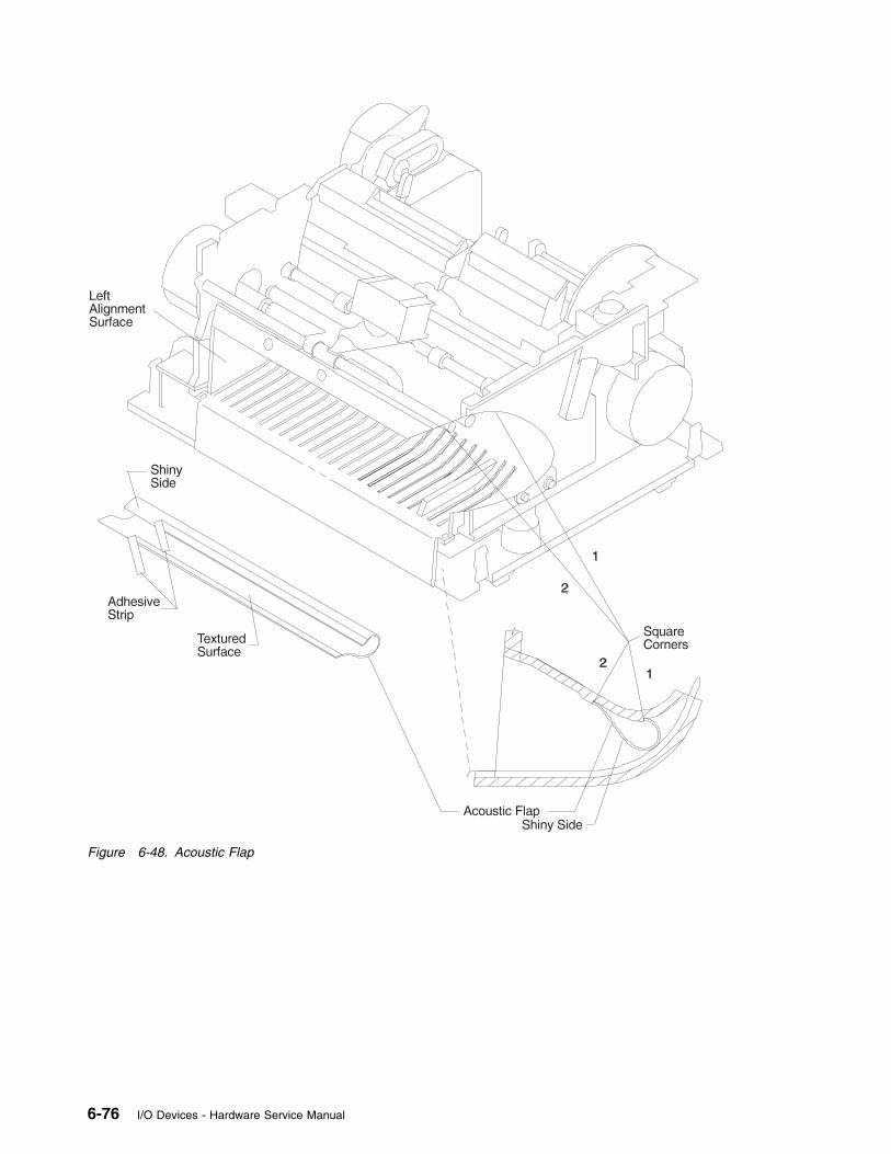
Figure 6-48. Acoustic Flap
6-76 I/O Devices - Hardware Service Manual
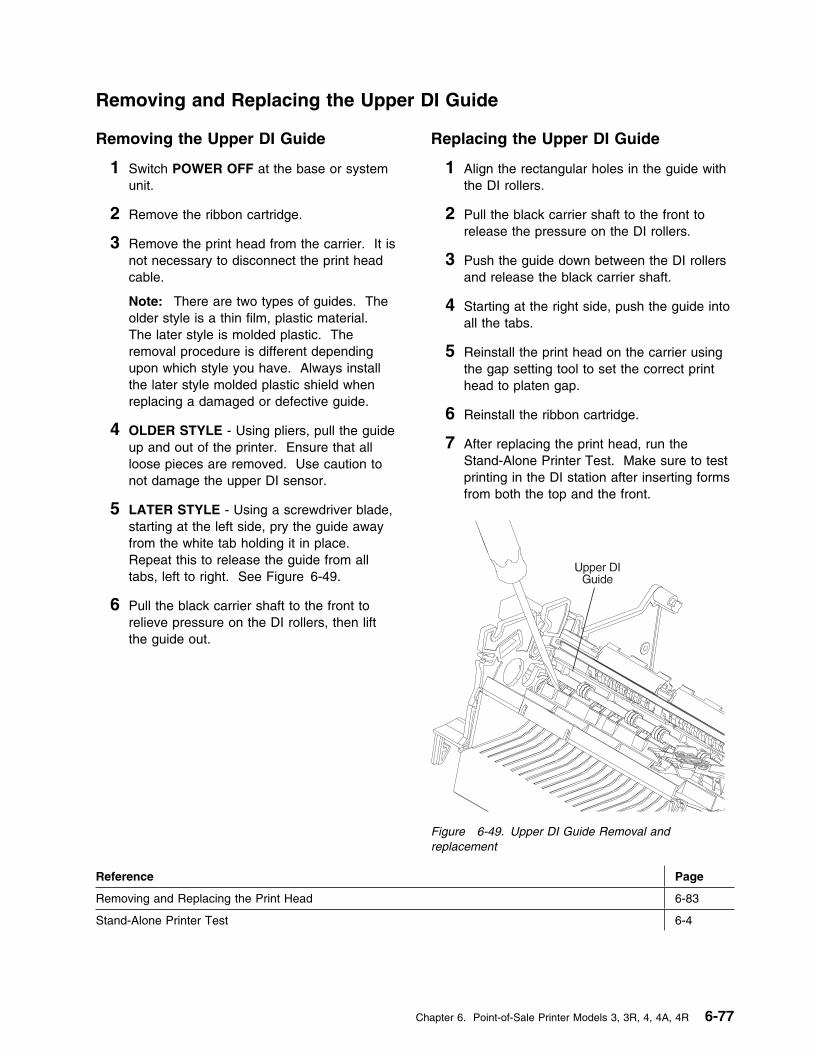
Removing and Replacing the Upper DI Guide
Removing the Upper DI Guide
1 Switch POWER OFF at the base or systemunit.
2 Remove the ribbon cartridge.
3 Remove the print head from the carrier. It isnot necessary to disconnect the print headcable.
Note: There are two types of guides. Theolder style is a thin film, plastic material.The later style is molded plastic. Theremoval procedure is different dependingupon which style you have. Always installthe later style molded plastic shield whenreplacing a damaged or defective guide.
4 OLDER STYLE - Using pliers, pull the guideup and out of the printer. Ensure that allloose pieces are removed. Use caution tonot damage the upper DI sensor.
5 LATER STYLE - Using a screwdriver blade,starting at the left side, pry the guide awayfrom the white tab holding it in place.Repeat this to release the guide from alltabs, left to right. See Figure 6-49.
6 Pull the black carrier shaft to the front torelieve pressure on the DI rollers, then liftthe guide out.
Replacing the Upper DI Guide
1 Align the rectangular holes in the guide withthe DI rollers.
2 Pull the black carrier shaft to the front torelease the pressure on the DI rollers.
3 Push the guide down between the DI rollersand release the black carrier shaft.
4 Starting at the right side, push the guide intoall the tabs.
5 Reinstall the print head on the carrier usingthe gap setting tool to set the correct printhead to platen gap.
6 Reinstall the ribbon cartridge.
7 After replacing the print head, run theStand-Alone Printer Test. Make sure to testprinting in the DI station after inserting formsfrom both the top and the front.
Figure 6-49. Upper DI Guide Removal andreplacement
Reference Page
Removing and Replacing the Print Head 6-83
Stand-Alone Printer Test 6-4
Chapter 6. Point-of-Sale Printer Models 3, 3R, 4, 4A, 4R 6-77

Removing and Replacing the Base
Removing the Base
1 Switch POWER OFF at the base or systemunit.
2 Disconnect the printer from the base orsystem unit.
3 Remove the main cover.
4 Remove the JNL spool.
5 Disconnect all of the cables from the printercard. See Figure 6-44 on page 6-69 for anillustration of the printer card. Make note ofhow the cables are routed for reinstallation.
6 Remove the printer card.
7 Rotate the printer onto its back with the basefacing you as shown.
8 Carefully release the two lower forms entrytabs (1) and (2), sequentially.
9 Release the base holding tabs (3), (4), (7) insequence according to the adjacentnumerals on the panel.
10 Disconnect the extension card ground leadfrom the ground clip.
11 Sequentially release the base holding tabs(5) and (6).
12 Pull the base off the printer.
Replacing the Base
1 Place the base on a flat surface.
2 Align the holding tabs on the printerassembly over the correspondingreceptacles in the base as shown inFigure 6-51 on page 6-79.
3 Reconnect the extension card ground lead tothe ground clip.
4 Carefully push on the printer until the basetabs lock into place.
Note: Ensure that the front tabs (1) and (2)are latched in place.
5 Reinstall the printer card.
6 Connect all of the cables to the printer card.See Figure 6-44 on page 6-69 for anillustration of the printer card. Route thecables as they were before.
7 Reinstall the JNL spool.
8 Reinstall the main cover.
9 Connect the printer to the base or systemunit.
10 Switch power ON at the base or system unit.
11 After replacing the base, run theStand-Alone Printer Test.
Reference Page
Removing and Replacing the Main Cover 6-114
Removing and Replacing the JNL Spool 6-112
Removing and Replacing the Printer Card 6-125
Stand-Alone Printer Test 6-4
6-78 I/O Devices - Hardware Service Manual
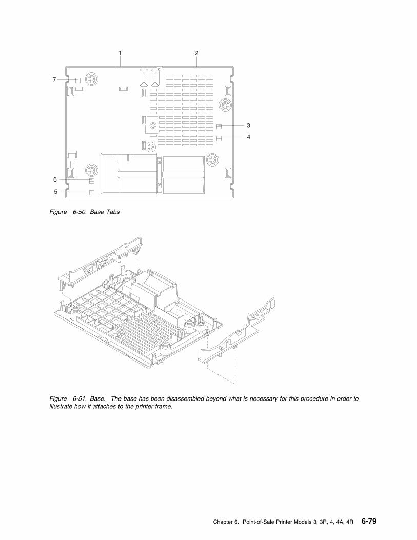
1 2
3
4
5
6
7
Figure 6-50. Base Tabs
Figure 6-51. Base. The base has been disassembled beyond what is necessary for this procedure in order toillustrate how it attaches to the printer frame.
Chapter 6. Point-of-Sale Printer Models 3, 3R, 4, 4A, 4R 6-79
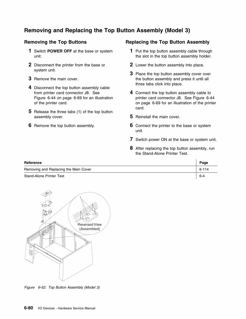
Removing and Replacing the Top Button Assembly (Model 3)
Removing the Top Buttons
1 Switch POWER OFF at the base or systemunit.
2 Disconnect the printer from the base orsystem unit.
3 Remove the main cover.
4 Disconnect the top button assembly cablefrom printer card connector J8. SeeFigure 6-44 on page 6-69 for an illustrationof the printer card.
5 Release the three tabs (1) of the top buttonassembly cover.
6 Remove the top button assembly.
Replacing the Top Button Assembly
1 Put the top button assembly cable throughthe slot in the top button assembly holder.
2 Lower the button assembly into place.
3 Place the top button assembly cover overthe button assembly and press it until allthree tabs click into place.
4 Connect the top button assembly cable toprinter card connector J8. See Figure 6-44on page 6-69 for an illustration of the printercard.
5 Reinstall the main cover.
6 Connect the printer to the base or systemunit.
7 Switch power ON at the base or system unit.
8 After replacing the top button assembly, runthe Stand-Alone Printer Test.
Reference Page
Removing and Replacing the Main Cover 6-114
Stand-Alone Printer Test 6-4
Reversed View(Assembled)
1
Figure 6-52. Top Button Assembly (Model 3)
6-80 I/O Devices - Hardware Service Manual
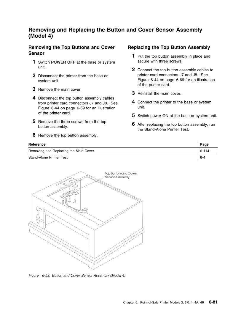
Removing and Replacing the Button and Cover Sensor Assembly(Model 4)
Removing the Top Buttons and CoverSensor
1 Switch POWER OFF at the base or systemunit.
2 Disconnect the printer from the base orsystem unit.
3 Remove the main cover.
4 Disconnect the top button assembly cablesfrom printer card connectors J7 and J8. SeeFigure 6-44 on page 6-69 for an illustrationof the printer card.
5 Remove the three screws from the topbutton assembly.
6 Remove the top button assembly.
Replacing the Top Button Assembly
1 Put the top button assembly in place andsecure with three screws.
2 Connect the top button assembly cables toprinter card connectors J7 and J8. SeeFigure 6-44 on page 6-69 for an illustrationof the printer card.
3 Reinstall the main cover.
4 Connect the printer to the base or systemunit.
5 Switch power ON at the base or system unit.
6 After replacing the top button assembly, runthe Stand-Alone Printer Test.
Reference Page
Removing and Replacing the Main Cover 6-114
Stand-Alone Printer Test 6-4
Figure 6-53. Button and Cover Sensor Assembly (Model 4)
Chapter 6. Point-of-Sale Printer Models 3, 3R, 4, 4A, 4R 6-81
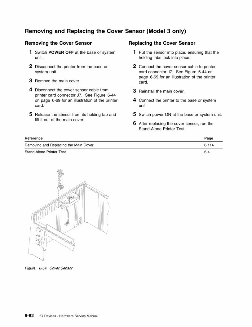
Removing and Replacing the Cover Sensor (Model 3 only)
Removing the Cover Sensor
1 Switch POWER OFF at the base or systemunit.
2 Disconnect the printer from the base orsystem unit.
3 Remove the main cover.
4 Disconnect the cover sensor cable fromprinter card connector J7. See Figure 6-44on page 6-69 for an illustration of the printercard.
5 Release the sensor from its holding tab andlift it out of the main cover.
Replacing the Cover Sensor
1 Put the sensor into place, ensuring that theholding tabs lock into place.
2 Connect the cover sensor cable to printercard connector J7. See Figure 6-44 onpage 6-69 for an illustration of the printercard.
3 Reinstall the main cover.
4 Connect the printer to the base or systemunit.
5 Switch power ON at the base or system unit.
6 After replacing the cover sensor, run theStand-Alone Printer Test.
Reference Page
Removing and Replacing the Main Cover 6-114
Stand-Alone Printer Test 6-4
Figure 6-54. Cover Sensor
6-82 I/O Devices - Hardware Service Manual
Removing and Replacing the Print Head
Removing the Print Head
1 Switch POWER OFF at the base or systemunit.
2 Disconnect the printer from the base orsystem unit.
3 Remove the main cover.
4 Remove the printer ribbon cartridge.
5 Remove the print head shield by gentlyspreading it at the bottom and lifting up.
6 Disconnect the print head cable from printercard connector J5. See Figure 6-44 onpage 6-69 for an illustration of the printercard.
Note: The print head cable is permanentlyattached to the print head.
7 Remove the two screws (1), lock washers,and special flat washers that attach the printhead to the carrier assembly.
8 Pull the carrier away from the platen so theprint head can slide forward off of its key.
9 Remove the print head and print head cablefrom the printer.
Service Hint
If print heads are being exchanged frequently,make sure that the recommended ribbons arebeing used. See “Expendable Supplies” onpage D-1.
Replacing the Print Head
1 Center the carrier in the printer. Pull thecarrier away from the platen to allow theprint head to engage the key on the carrier.
2 Loosely screw the print head to the carrier
using the screws, lock washers, and specialflat washers as shown.
3 Use the gap setting tool as shown inFigure 6-56 on page 6-85 to set the correctgap between the print head and platen.Latch the tool in front of the print head asshown and move the print head forward onthe carrier until the tool is flush with theplaten.
4 Screw the print head onto the carrier asshown. Torque both screws using a torquescrewdriver with a T10 Torx bit set at 6inch-pounds (0.69Nm). Do not overtightenthe screws. Remove the adjustment tooland reinstall the print head shield.
5 Tuck the print head cable under the rib onthe carrier and move the carrier to the rightside of the printer. See Figure 6-57 onpage 6-85. Slide the cable under the homesensor card assembly and then route itthrough the left side frame. The 90 degreebend in the cable should be flush with theslot in the left side frame.
6 Connect the print head cable to printer cardconnector J5. See Figure 6-44 onpage 6-69 for an illustration of the printercard.
7 Reinstall the printer ribbon cartridge.
8 Reinstall the main cover.
9 Connect the printer to the base or systemunit.
10 Switch power ON at the base or system unit.
11 Press the Ready button, the DI up button,and the DI down button simultaneously.
12 After replacing the print head, run theStand-Alone Printer Test. Also, perform theprinter adjustments.
Chapter 6. Point-of-Sale Printer Models 3, 3R, 4, 4A, 4R 6-83

Reference Page
Removing and Replacing the Main Cover 6-114
Printer Adjustments 6-67
Stand-Alone Printer Test 6-4
1
Print HeadShield
Print Head
Figure 6-55. Print Head
6-84 I/O Devices - Hardware Service Manual
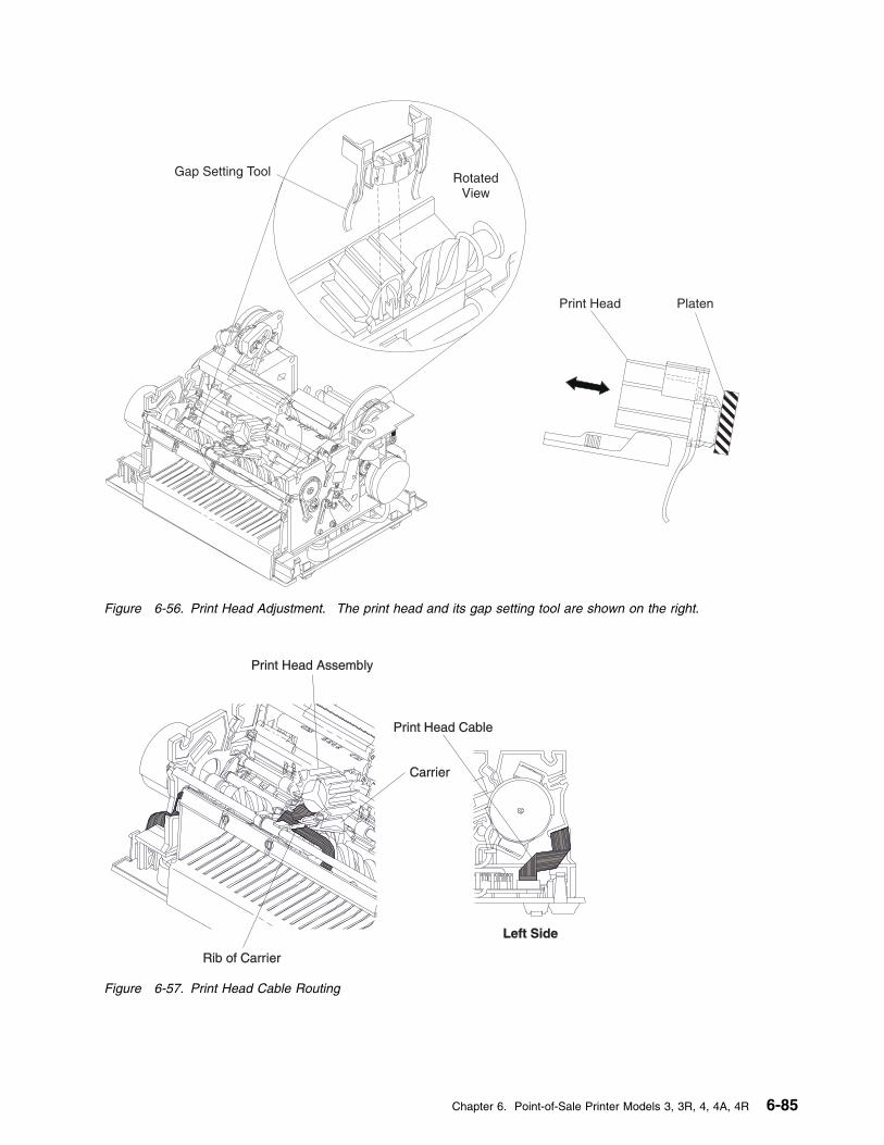
Gap Setting Tool
Print Head Platen
RotatedView
Figure 6-56. Print Head Adjustment. The print head and its gap setting tool are shown on the right.
Print Head Assembly
Carrier
Print Head Cable
Rib of Carrier
Left Side
Figure 6-57. Print Head Cable Routing
Chapter 6. Point-of-Sale Printer Models 3, 3R, 4, 4A, 4R 6-85
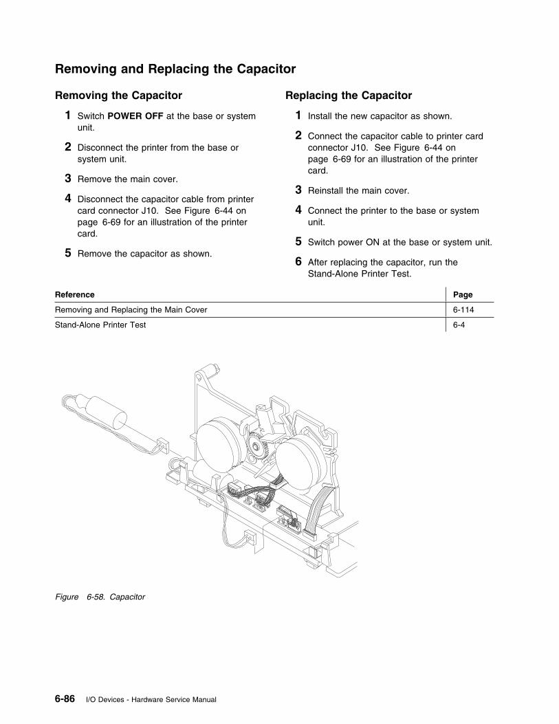
Removing and Replacing the Capacitor
Removing the Capacitor
1 Switch POWER OFF at the base or systemunit.
2 Disconnect the printer from the base orsystem unit.
3 Remove the main cover.
4 Disconnect the capacitor cable from printercard connector J10. See Figure 6-44 onpage 6-69 for an illustration of the printercard.
5 Remove the capacitor as shown.
Replacing the Capacitor
1 Install the new capacitor as shown.
2 Connect the capacitor cable to printer cardconnector J10. See Figure 6-44 onpage 6-69 for an illustration of the printercard.
3 Reinstall the main cover.
4 Connect the printer to the base or systemunit.
5 Switch power ON at the base or system unit.
6 After replacing the capacitor, run theStand-Alone Printer Test.
Reference Page
Removing and Replacing the Main Cover 6-114
Stand-Alone Printer Test 6-4
Figure 6-58. Capacitor
6-86 I/O Devices - Hardware Service Manual
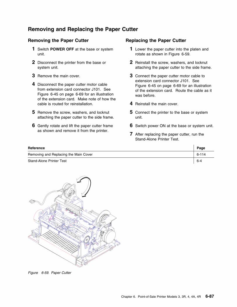
Removing and Replacing the Paper Cutter
Removing the Paper Cutter
1 Switch POWER OFF at the base or systemunit.
2 Disconnect the printer from the base orsystem unit.
3 Remove the main cover.
4 Disconnect the paper cutter motor cablefrom extension card connector J101. SeeFigure 6-45 on page 6-69 for an illustrationof the extension card. Make note of how thecable is routed for reinstallation.
5 Remove the screw, washers, and locknutattaching the paper cutter to the side frame.
6 Gently rotate and lift the paper cutter frameas shown and remove it from the printer.
Replacing the Paper Cutter
1 Lower the paper cutter into the platen androtate as shown in Figure 6-59.
2 Reinstall the screw, washers, and locknutattaching the paper cutter to the side frame.
3 Connect the paper cutter motor cable toextension card connector J101. SeeFigure 6-45 on page 6-69 for an illustrationof the extension card. Route the cable as itwas before.
4 Reinstall the main cover.
5 Connect the printer to the base or systemunit.
6 Switch power ON at the base or system unit.
7 After replacing the paper cutter, run theStand-Alone Printer Test.
Reference Page
Removing and Replacing the Main Cover 6-114
Stand-Alone Printer Test 6-4
Figure 6-59. Paper Cutter
Chapter 6. Point-of-Sale Printer Models 3, 3R, 4, 4A, 4R 6-87
Removing and Replacing the CR Motor
Removing the CR Motor
1 Switch POWER OFF at the base or systemunit.
2 Disconnect the printer from the base orsystem unit.
3 Remove the main cover.
4 Remove the paper cutter.
5 Unlatch the CR motor mount and tilt it up,but do not remove the motor gear assembly.See step 5 on page 6-90 under Removingthe CR Motor Gear Assembly.
6 Disconnect the motor cable from extensioncard connector J102. See Figure 6-45 onpage 6-69 for an illustration of the extensioncard. Make note of how the cable is routedfor reinstallation.
7 Insert 2 screwdrivers into the CR motor gearassembly as shown. See Figure 6-60 onpage 6-89. Turn the screwdrivers inopposite directions and gently pry the metalflange on the motor in the direction shownuntil the motor is released from the tabs.
8 Slide the motor out of the assembly.
Note: Ensure that the two gears in theassembly do not fall off of their posts.
Replacing the CR Motor
1 Slide the CR motor into the motor gearassembly and turn the motorcounterclockwise until it clicks into place.Verify that the gears are correctly engaged.
2 Connect the motor cable to extension cardconnector J102. See Figure 6-45 onpage 6-69 for an illustration of the extensioncard. Route the cable as it was before.
3 Press the CR motor gear assembly downuntil it clicks into place.
Note: Ensure that the bearing is still in itsslot in the motor gear assembly.
4 Reinstall the paper cutter.
5 Reinstall the main cover.
6 Connect the printer to the base or systemunit.
7 Switch power ON at the base or system unit.
8 After replacing the CR motor, run theStand-Alone Printer Test.
Reference Page
Removing and Replacing the Main Cover 6-114
Removing and Replacing the Paper Cutter 6-87
Stand-Alone Printer Test 6-4
6-88 I/O Devices - Hardware Service Manual
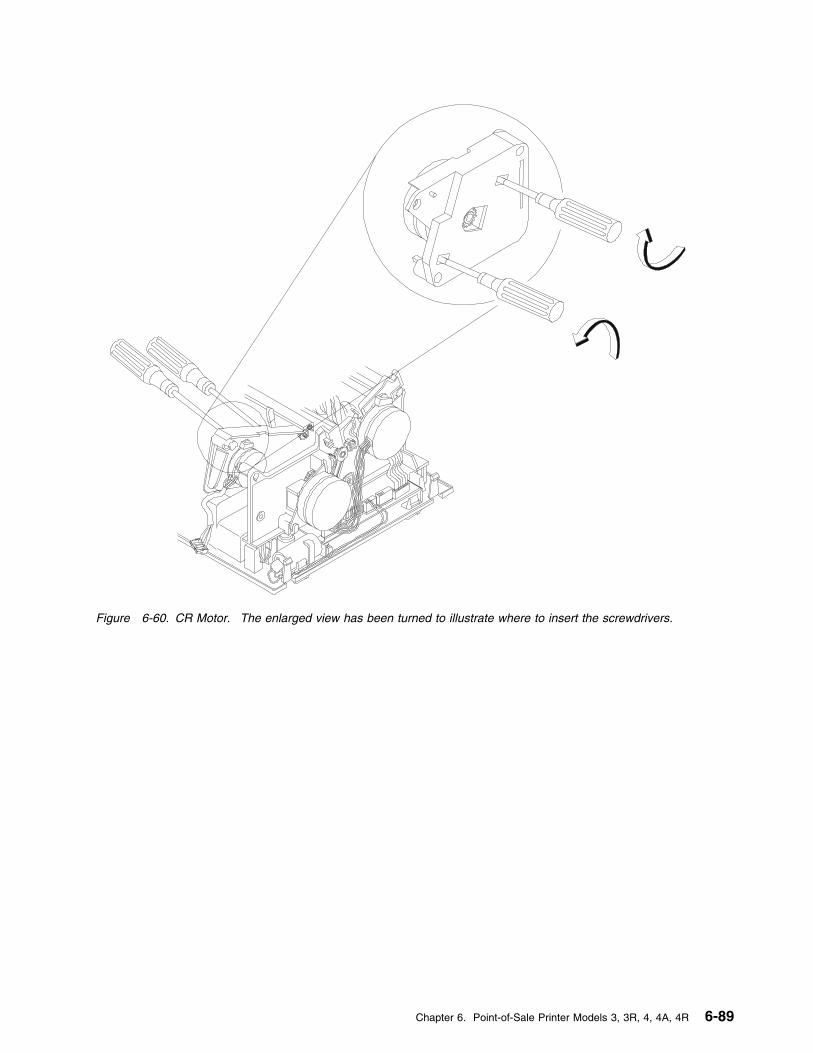
Figure 6-60. CR Motor. The enlarged view has been turned to illustrate where to insert the screwdrivers.
Chapter 6. Point-of-Sale Printer Models 3, 3R, 4, 4A, 4R 6-89
Removing and Replacing the CR Motor Gear Assembly
Removing the CR Motor GearAssembly
1 Switch POWER OFF at the base or systemunit.
2 Disconnect the printer from the base orsystem unit.
3 Remove the main cover.
4 Remove the paper cutter.
5 Pull out the tab on the CR motor gearassembly and raise it up until it is free fromthe tab.
6 Disconnect the CR motor cable fromextension card connector J102. SeeFigure 6-45 on page 6-69 for an illustrationof the extension card. Make note of how thecable is routed for reinstallation.
7 Remove the CR feed roll gear from the endof the CR shaft by lifting the locking tab onthe gear and using a screwdriver to push thegear off the shaft.
8 Remove the feed roll gear bearing.
9 Remove the CR motor gear assembly.
Replacing the CR Motor GearAssembly
1 Put the CR motor gear assembly on theplaten assembly and reinstall the D-shapedbearing and gear on the end of the CR shaftas shown. Ensure that the gear snaps intoplace.
2 Connect the CR motor cable to printerextension card connector J102. SeeFigure 6-45 on page 6-69 for an illustrationof the extension card. Route the cable as itwas before.
3 Press the motor gear assembly down untilthe tab clicks into place.
Note: Ensure that the bearing is still in itsslot in the motor gear assembly.
4 Reinstall the paper cutter.
5 Reinstall the main cover.
6 Connect the printer to the base or systemunit.
7 Switch power ON at the base or system unit.
8 After replacing the CR motor gear assembly,run the Stand-Alone Printer Test. See page6-4.
Reference Page
Removing and Replacing the Main Cover 6-114
Removing and Replacing the Paper Cutter 6-87
Stand-Alone Printer Test 6-4
6-90 I/O Devices - Hardware Service Manual
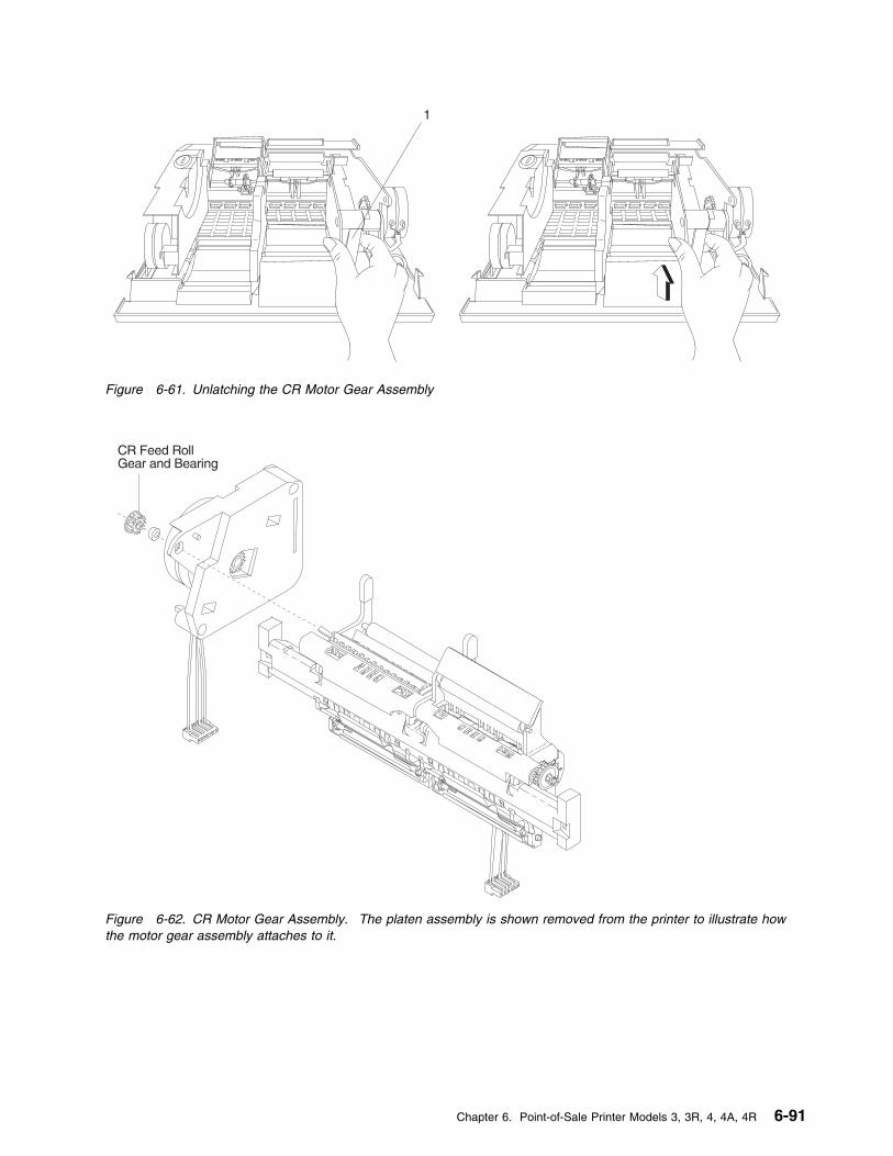
1
Figure 6-61. Unlatching the CR Motor Gear Assembly
Figure 6-62. CR Motor Gear Assembly. The platen assembly is shown removed from the printer to illustrate howthe motor gear assembly attaches to it.
Chapter 6. Point-of-Sale Printer Models 3, 3R, 4, 4A, 4R 6-91
Removing and Replacing the CR Roller Assembly
Removing the CR Roller Assembly
1 Switch POWER OFF at the base or systemunit.
2 Disconnect the printer from the base orsystem unit.
3 Remove the main cover.
4 Remove the paper cutter.
5 Remove the platen assembly.
6 Remove the toggle spring retainer clip (2),then disengage the toggle spring (1) at itscenter attachment point.
7 Remove the roller leg retainer (4) then gentlypry outward on the ends of the CR rollerassembly (5) until they are free of the postson the CR frame.
8 Remove the CR roller assembly and notehow it attaches to the frame.
9 Gently spread the top sides of the CR frameone side at a time until they are loose fromthe platen and rotate the frame off of theplaten as shown.
Note: The rubber pads on the platen maycome off.
Replacing the CR Roller Assembly
1 Attach the bottom of the CR frame to theplaten and rotate it forward as shown untilthe top sides of the frame touch the platen.Gently spread the top sides one at a timeand continue rotating the frame until it clicksinto place.
2 Check that the rubber pads keep the frametight with the platen.
3 Gently spread the arms of the roller to allowits holes to fit over the posts on the frame.Reinstall the roller leg retainer (4).
4 Attach the toggle spring (1) at its centerattachment point then install the togglespring retainer clip (2). Ensure that thespring is correctly seated and that the rollermoves back-and-forth correctly.
5 Check that the ends of the bail springs (3)are positioned correctly.
6 Reinstall the platen assembly.
7 Reinstall the paper cutter.
8 Reinstall the main cover.
9 Connect the printer to the base or systemunit.
10 Switch power ON at the base or system unit.
11 After replacing the CR components, run theStand-Alone Printer Test.
Reference Page
Removing and Replacing the Main Cover 6-114
Removing and Replacing the Paper Cutter 6-87
Removing and Replacing the Platen Assembly 6-116
Stand-Alone Printer Test 6-4
6-92 I/O Devices - Hardware Service Manual
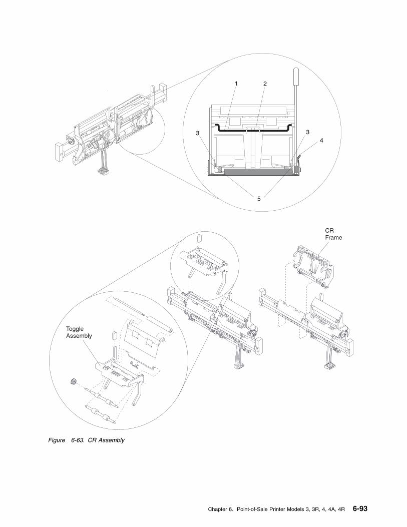
1 2
34
5
3
ToggleAssembly
CRFrame
Figure 6-63. CR Assembly
Chapter 6. Point-of-Sale Printer Models 3, 3R, 4, 4A, 4R 6-93

Removing and Replacing the DI Motor
Removing the DI Motor
1 Switch POWER OFF at the base or systemunit.
2 Disconnect the printer from the base orsystem unit.
3 Remove the main cover.
4 Disconnect the motor cable from printer cardconnector J3. See Figure 6-44 onpage 6-69 for an illustration of the printercard. Make note of how the cable is routedfor reinstallation.
5 Insert a screwdriver under the DI tab asshown. Try to keep the screwdriver bladeflush to the tab.
Attention Do not pry outward on the plastictabs. They may break off and require areplacement printer.
6 Insert another screwdriver under the othermotor flange as shown.
7 With the screwdrivers, gently pry the metalflanges on the motor in the direction shownuntil the motor rotates clockwise and isreleased from the tabs.
Replacing the DI Motor
1 Slide the DI motor into the printer as shownand turn the motor counterclockwise until itclicks into place.
2 Connect the motor cable to printer cardconnector J3. See Figure 6-44 onpage 6-69 for an illustration of the printercard. Route the cable as it was before.
3 Reinstall the main cover.
4 Connect the printer to the base or systemunit.
5 Switch power ON at the base or system unit.
6 After replacing the DI motor, run theStand-Alone Printer Test.
Reference Page
Removing and Replacing the Main Cover 6-114
Stand-Alone Printer Test 6-4
6-94 I/O Devices - Hardware Service Manual
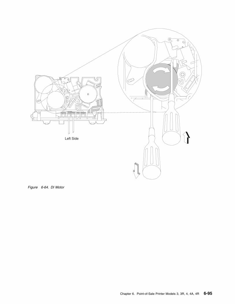
Left Side
Figure 6-64. DI Motor
Chapter 6. Point-of-Sale Printer Models 3, 3R, 4, 4A, 4R 6-95
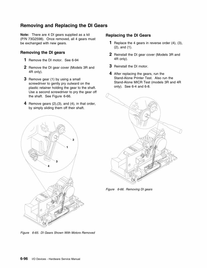
Removing and Replacing the DI Gears
Note: There are 4 DI gears supplied as a kit(P/N 73G2598). Once removed, all 4 gears mustbe exchanged with new gears.
Removing the DI gears
1 Remove the DI motor. See 6-94
2 Remove the DI gear cover (Models 3R and4R only).
3 Remove gear (1) by using a smallscrewdriver to gently pry outward on theplastic retainer holding the gear to the shaft.Use a second screwdriver to pry the gear offthe shaft. See Figure 6-66.
4 Remove gears (2),(3), and (4), in that order,by simply sliding them off their shaft.
Figure 6-65. DI Gears Shown With Motors Removed
Replacing the DI Gears
1 Replace the 4 gears in reverse order (4), (3),(2), and (1).
2 Reinstall the DI gear cover (Models 3R and4R only).
3 Reinstall the DI motor.
4 After replacing the gears, run theStand-Alone Printer Test. Also run theStand-Alone MICR Test (models 3R and 4Ronly). See 6-4 and 6-8.
Figure 6-66. Removing DI gears
6-96 I/O Devices - Hardware Service Manual
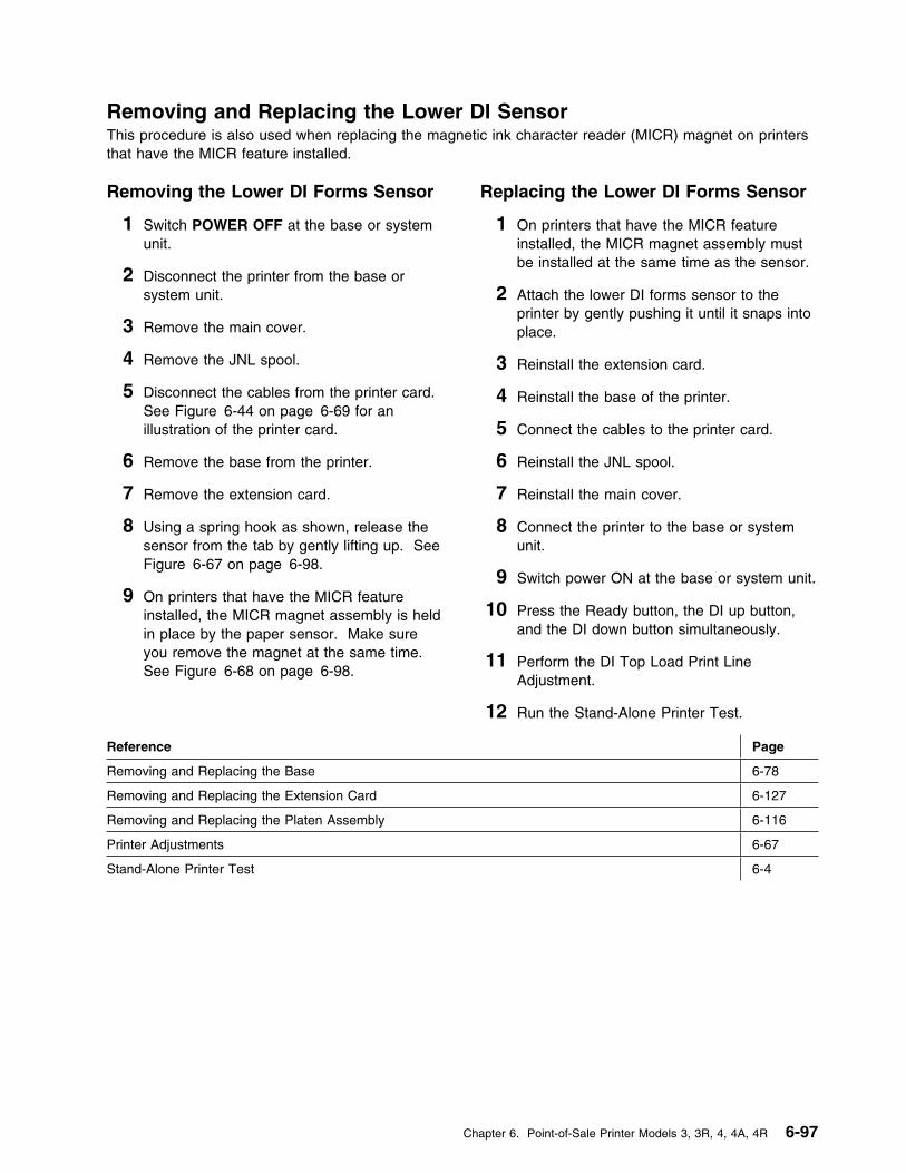
Removing and Replacing the Lower DI SensorThis procedure is also used when replacing the magnetic ink character reader (MICR) magnet on printersthat have the MICR feature installed.
Removing the Lower DI Forms Sensor
1 Switch POWER OFF at the base or systemunit.
2 Disconnect the printer from the base orsystem unit.
3 Remove the main cover.
4 Remove the JNL spool.
5 Disconnect the cables from the printer card.See Figure 6-44 on page 6-69 for anillustration of the printer card.
6 Remove the base from the printer.
7 Remove the extension card.
8 Using a spring hook as shown, release thesensor from the tab by gently lifting up. SeeFigure 6-67 on page 6-98.
9 On printers that have the MICR featureinstalled, the MICR magnet assembly is heldin place by the paper sensor. Make sureyou remove the magnet at the same time.See Figure 6-68 on page 6-98.
Replacing the Lower DI Forms Sensor
1 On printers that have the MICR featureinstalled, the MICR magnet assembly mustbe installed at the same time as the sensor.
2 Attach the lower DI forms sensor to theprinter by gently pushing it until it snaps intoplace.
3 Reinstall the extension card.
4 Reinstall the base of the printer.
5 Connect the cables to the printer card.
6 Reinstall the JNL spool.
7 Reinstall the main cover.
8 Connect the printer to the base or systemunit.
9 Switch power ON at the base or system unit.
10 Press the Ready button, the DI up button,and the DI down button simultaneously.
11 Perform the DI Top Load Print LineAdjustment.
12 Run the Stand-Alone Printer Test.
Reference Page
Removing and Replacing the Base 6-78
Removing and Replacing the Extension Card 6-127
Removing and Replacing the Platen Assembly 6-116
Printer Adjustments 6-67
Stand-Alone Printer Test 6-4
Chapter 6. Point-of-Sale Printer Models 3, 3R, 4, 4A, 4R 6-97
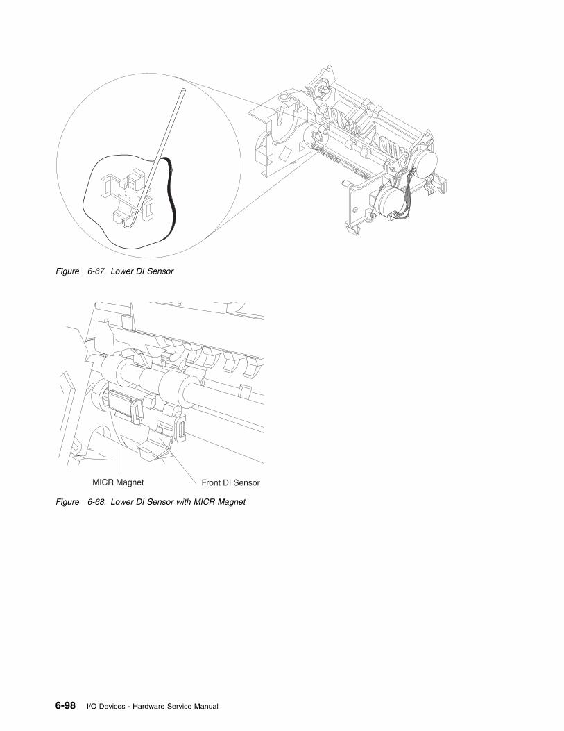
Figure 6-67. Lower DI Sensor
MICR Magnet Front DI Sensor
Figure 6-68. Lower DI Sensor with MICR Magnet
6-98 I/O Devices - Hardware Service Manual

Removing and Replacing the Upper DI Sensor
Removing the Upper DI Sensor
1 Switch POWER OFF at the base or systemunit.
2 Disconnect the printer from the base orsystem unit.
3 Remove the main cover.
4 Disconnect the sensor cable from theextension card connector J109. SeeFigure 6-45 on page 6-69 for an illustrationof the extension card. Make note of how thecable is routed for reinstallation.
5 Remove the screw (1).
6 On printers that have the MICR feature or aplaten filler where the MICR is normallyinstalled, there is not enough room to allowthe sensor cable and connector to beremoved. If this is the case, the platenassembly must be loosened and raisedenough to allow the sensor cable andconnector to be removed.
7 Remove the upper DI sensor from the rightside frame, carefully threading the cable andconnector out of the printer.
Replacing the Upper DI Sensor
1 Align the pins in the sensor with the holes inthe right side frame.
2 Attach the upper DI forms sensor to the rightside frame using the screw (1).
3 Connect the sensor cable to the extensioncard connector J109. See Figure 6-45 onpage 6-69 for an illustration of the extensioncard. Route the cable as it was before.
4 Retighten the platen if was it loosenedduring the removal.
5 Reinstall the main cover.
6 Connect the printer to the base or systemunit.
7 Switch power ON at the base or system unit.
8 Press the Ready button, the DI up button,and the DI down button simultaneously.
9 Perform the DI Front Load Print LineAdjustment.
10 After replacing the upper DI forms sensor,run the Stand-Alone Printer Test.
Reference Page
Removing and Replacing the Main Cover 6-114
Removing and Replacing the Platen Assembly 6-116
DI Front Load Print Line Adjustment 6-67
Stand-Alone Printer Test 6-4
Figure 6-69. Upper DI Forms Sensor
Chapter 6. Point-of-Sale Printer Models 3, 3R, 4, 4A, 4R 6-99
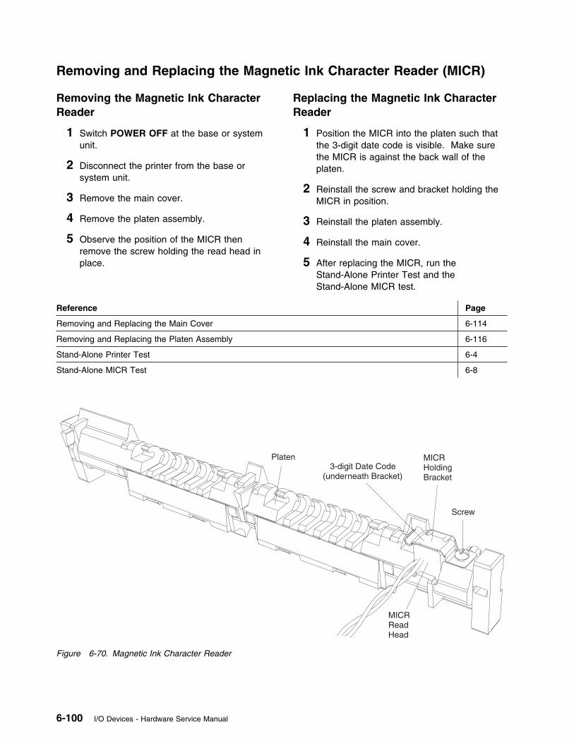
Removing and Replacing the Magnetic Ink Character Reader (MICR)
Removing the Magnetic Ink CharacterReader
1 Switch POWER OFF at the base or systemunit.
2 Disconnect the printer from the base orsystem unit.
3 Remove the main cover.
4 Remove the platen assembly.
5 Observe the position of the MICR thenremove the screw holding the read head inplace.
Replacing the Magnetic Ink CharacterReader
1 Position the MICR into the platen such thatthe 3-digit date code is visible. Make surethe MICR is against the back wall of theplaten.
2 Reinstall the screw and bracket holding theMICR in position.
3 Reinstall the platen assembly.
4 Reinstall the main cover.
5 After replacing the MICR, run theStand-Alone Printer Test and theStand-Alone MICR test.
Reference Page
Removing and Replacing the Main Cover 6-114
Removing and Replacing the Platen Assembly 6-116
Stand-Alone Printer Test 6-4
Stand-Alone MICR Test 6-8
Platen
Screw
MICRHoldingBracket
MICRReadHead
3-digit Date Code(underneath Bracket)
Figure 6-70. Magnetic Ink Character Reader
6-100 I/O Devices - Hardware Service Manual
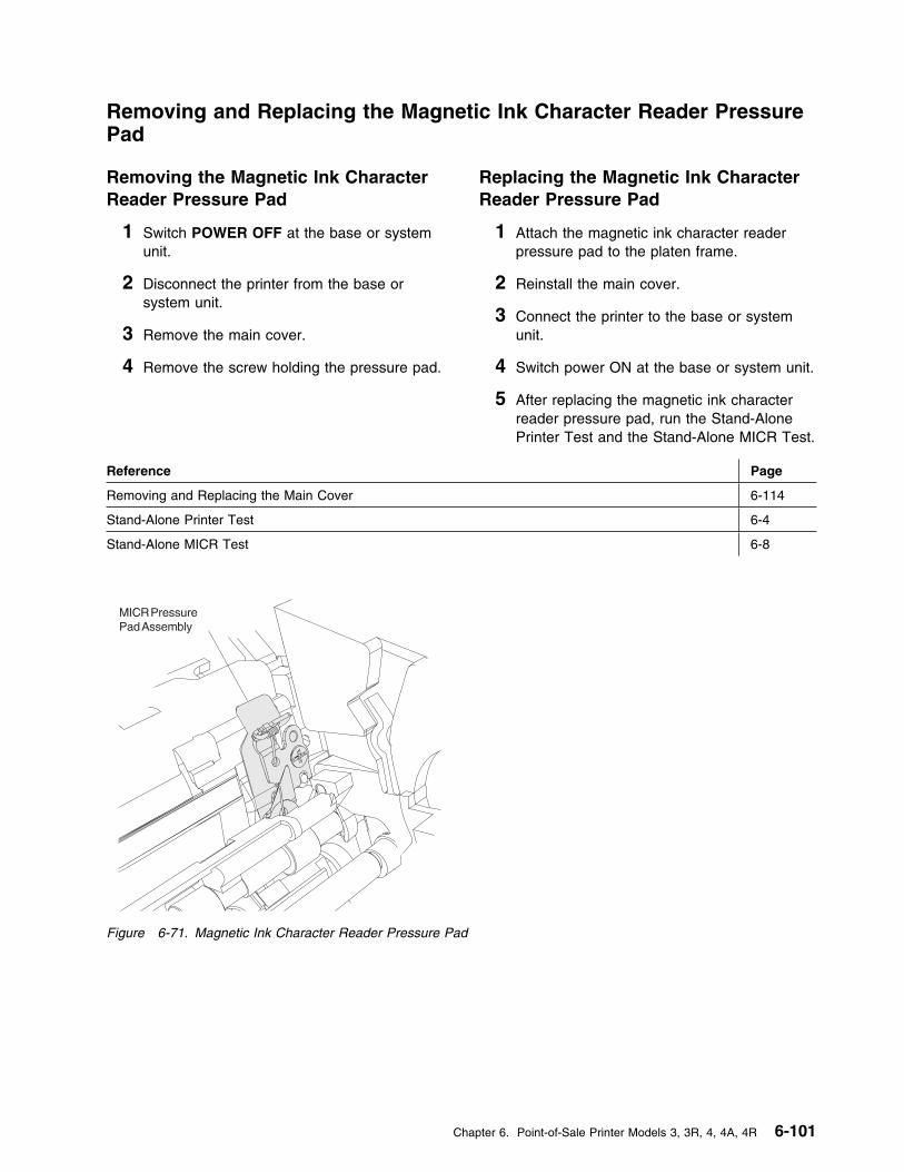
Removing and Replacing the Magnetic Ink Character Reader PressurePad
Removing the Magnetic Ink CharacterReader Pressure Pad
1 Switch POWER OFF at the base or systemunit.
2 Disconnect the printer from the base orsystem unit.
3 Remove the main cover.
4 Remove the screw holding the pressure pad.
Replacing the Magnetic Ink CharacterReader Pressure Pad
1 Attach the magnetic ink character readerpressure pad to the platen frame.
2 Reinstall the main cover.
3 Connect the printer to the base or systemunit.
4 Switch power ON at the base or system unit.
5 After replacing the magnetic ink characterreader pressure pad, run the Stand-AlonePrinter Test and the Stand-Alone MICR Test.
Reference Page
Removing and Replacing the Main Cover 6-114
Stand-Alone Printer Test 6-4
Stand-Alone MICR Test 6-8
Figure 6-71. Magnetic Ink Character Reader Pressure Pad
Chapter 6. Point-of-Sale Printer Models 3, 3R, 4, 4A, 4R 6-101
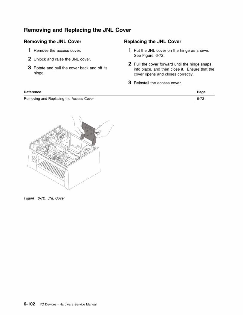
Removing and Replacing the JNL Cover
Removing the JNL Cover
1 Remove the access cover.
2 Unlock and raise the JNL cover.
3 Rotate and pull the cover back and off itshinge.
Replacing the JNL Cover
1 Put the JNL cover on the hinge as shown.See Figure 6-72.
2 Pull the cover forward until the hinge snapsinto place, and then close it. Ensure that thecover opens and closes correctly.
3 Reinstall the access cover.
Reference Page
Removing and Replacing the Access Cover 6-73
Figure 6-72. JNL Cover
6-102 I/O Devices - Hardware Service Manual
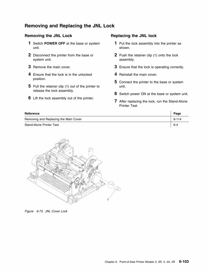
Removing and Replacing the JNL Lock
Removing the JNL Lock
1 Switch POWER OFF at the base or systemunit.
2 Disconnect the printer from the base orsystem unit.
3 Remove the main cover.
4 Ensure that the lock is in the unlockedposition.
5 Pull the retainer clip (1) out of the printer torelease the lock assembly.
6 Lift the lock assembly out of the printer.
Replacing the JNL lock
1 Put the lock assembly into the printer asshown.
2 Push the retainer clip (1) onto the lockassembly.
3 Ensure that the lock is operating correctly.
4 Reinstall the main cover.
5 Connect the printer to the base or systemunit.
6 Switch power ON at the base or system unit.
7 After replacing the lock, run the Stand-AlonePrinter Test.
Reference Page
Removing and Replacing the Main Cover 6-114
Stand-Alone Printer Test 6-4
1
Figure 6-73. JNL Cover Lock
Chapter 6. Point-of-Sale Printer Models 3, 3R, 4, 4A, 4R 6-103
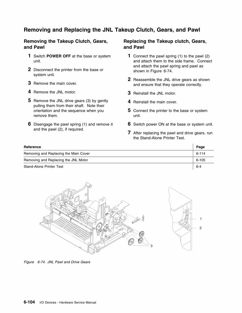
Removing and Replacing the JNL Takeup Clutch, Gears, and Pawl
Removing the Takeup Clutch, Gears,and Pawl
1 Switch POWER OFF at the base or systemunit.
2 Disconnect the printer from the base orsystem unit.
3 Remove the main cover.
4 Remove the JNL motor.
5 Remove the JNL drive gears (3) by gentlypulling them from their shaft. Note theirorientation and the sequence when youremove them.
6 Disengage the pawl spring (1) and remove itand the pawl (2), if required.
Replacing the Takeup clutch, Gears,and Pawl
1 Connect the pawl spring (1) to the pawl (2)and attach them to the side frame. Connectand attach the pawl spring and pawl asshown in Figure 6-74.
2 Reassemble the JNL drive gears as shownand ensure that they operate correctly.
3 Reinstall the JNL motor.
4 Reinstall the main cover.
5 Connect the printer to the base or systemunit.
6 Switch power ON at the base or system unit.
7 After replacing the pawl and drive gears, runthe Stand-Alone Printer Test.
Reference Page
Removing and Replacing the Main Cover 6-114
Removing and Replacing the JNL Motor 6-105
Stand-Alone Printer Test 6-4
3
1
2
Figure 6-74. JNL Pawl and Drive Gears
6-104 I/O Devices - Hardware Service Manual
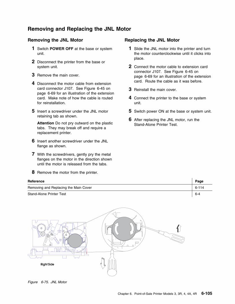
Removing and Replacing the JNL Motor
Removing the JNL Motor
1 Switch POWER OFF at the base or systemunit.
2 Disconnect the printer from the base orsystem unit.
3 Remove the main cover.
4 Disconnect the motor cable from extensioncard connector J107. See Figure 6-45 onpage 6-69 for an illustration of the extensioncard. Make note of how the cable is routedfor reinstallation.
5 Insert a screwdriver under the JNL motorretaining tab as shown.
Attention Do not pry outward on the plastictabs. They may break off and require areplacement printer.
6 Insert another screwdriver under the JNLflange as shown.
7 With the screwdrivers, gently pry the metalflanges on the motor in the direction shownuntil the motor is released from the tabs.
8 Remove the motor from the printer.
Replacing the JNL Motor
1 Slide the JNL motor into the printer and turnthe motor counterclockwise until it clicks intoplace.
2 Connect the motor cable to extension cardconnector J107. See Figure 6-45 onpage 6-69 for an illustration of the extensioncard. Route the cable as it was before.
3 Reinstall the main cover.
4 Connect the printer to the base or systemunit.
5 Switch power ON at the base or system unit.
6 After replacing the JNL motor, run theStand-Alone Printer Test.
Reference Page
Removing and Replacing the Main Cover 6-114
Stand-Alone Printer Test 6-4
Figure 6-75. JNL Motor
Chapter 6. Point-of-Sale Printer Models 3, 3R, 4, 4A, 4R 6-105
Removing and Replacing the JNL Paper Motion Sensor
Removing the JNL Paper MotionSensor
1 Switch POWER OFF at the base or systemunit.
2 Disconnect the printer from the base orsystem unit.
3 Remove the main cover.
4 Disconnect all cables from the printer card.See Figure 6-44 on page 6-69 for anillustration of the printer card.
5 Remove the base.
6 Disconnect the JNL paper motion sensorcable from printer extension card connectorJ106. See Figure 6-45 on page 6-69 for anillustration of the extension card. Make noteof how the cable is routed for reinstallation.
7 Remove the JNL emitter wheel shaft (1) bygently prying the shaft out of the JNL frameat each end.
8 Using a springhook, remove the sensor clipby gently lifting the small end until the cliprotates out and allows the removal of theJNL paper motion sensor.
Replacing the JNL Paper MotionSensor
1 Exchange the JNL paper motion sensor andinstall the sensor clip by placing the largeside of the clip against the sensor mount androtating the small end through the sensoruntil it snaps into place. Ensure that thesensor is seated firmly.
2 Reinstall the JNL emitter wheel (2) and shaft(1).
3 Connect the JNL paper motion sensor cableto extension card connector J106. SeeFigure 6-45 on page 6-69 for an illustrationof the extension card. Route the cable as itwas before.
4 Reinstall the base.
5 Connect all cables to the printer card. SeeFigure 6-44 on page 6-69 for an illustrationof the printer card.
6 Reinstall the main cover.
7 Connect the printer to the base or systemunit.
8 Switch power ON at the base or system unit.
9 After replacing the JNL paper motion sensor,run the Stand-Alone Printer Test.
Reference Page
Removing and Replacing the Main Cover 6-114
Removing and Replacing the Base 6-78
Stand-Alone Printer Test 6-4
6-106 I/O Devices - Hardware Service Manual
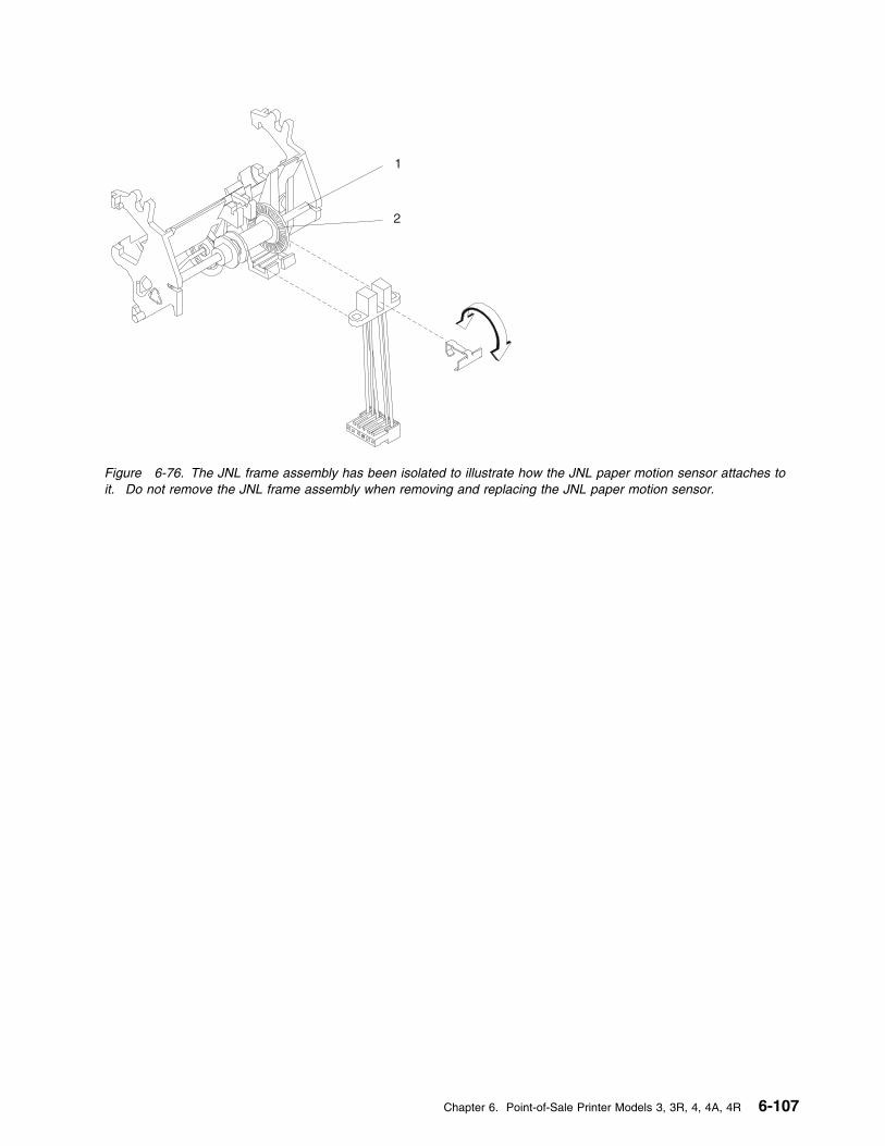
1
2
Figure 6-76. The JNL frame assembly has been isolated to illustrate how the JNL paper motion sensor attaches toit. Do not remove the JNL frame assembly when removing and replacing the JNL paper motion sensor.
Chapter 6. Point-of-Sale Printer Models 3, 3R, 4, 4A, 4R 6-107
Removing and Replacing the JNL Roller Assembly and Frame
Removing the JNL Assembly
1 Switch POWER OFF at the base or systemunit.
2 Disconnect the printer from the base orsystem unit.
3 Remove the main cover.
4 Remove the platen assembly.
5 Remove the toggle spring retainer clip (2)then disengage the spring toggle (1) at itscenter attachment point.
6 Disengage the O-ring shaft (3) from theinside leg of the roller and slide the shaft outthe hole in the outside leg of the roller.
7 Remove the roller leg retainer (6) then gentlypry outward on the ends of the JNL rollerassembly (5) until they are free of the postson the JNL frame. Remove the JNL rollerassembly and make note of how it attachesto the frame.
8 Gently spread the top sides of the JNL frameone at a time until they are loose from theplaten and rotate the frame off of the platenas shown.
Note: The rubber pads on the platen maycome off.
Replacing the JNL Assembly
1 Attach the bottom of the JNL frame to theplaten and rotate it forward as shown untilthe top sides of the frame touch the platen.Gently spread the top sides one at a timeand continue rotating the frame forward untilboth sides click into place. Check that therubber pads keep the frame tight against theplaten.
2 Gently spread the arms of the roller to allowthe holes to fit over the posts on the frame.Reinstall the roller leg retainer (6).
3 Attach the toggle spring (1) at its centerattachment point then install the togglespring retainer clip (2). Ensure that thespring is correctly seated and that the rollermoves back-and-forth correctly.
4 Ensure that the O-ring shaft is seatedproperly. The shaft should be held on bothsides of the JNL roller. The O-ring shaftshould move up and down in the slot nearthe O-ring as the JNL roller holder is toggledfrom the feed to the load position.
5 Reinstall the O-ring shaft (3) by inserting itthrough the hole in the outside leg of theroller, then snapping the shaft into the insideleg of the roller. Check that the bail springs(4) are correctly positioned. SeeFigure 6-77 on page 6-109.
6 Reinstall the platen assembly.
7 Reinstall the main cover.
8 Connect the printer to the base or systemunit.
9 Switch power ON at the base or system unit.
10 After replacing the JNL components, run theStand-Alone Printer Test.
Reference Page
Removing and Replacing the Main Cover 6-114
Removing and Replacing the Platen assembly 6-116
Stand-Alone Printer Test 6-4
6-108 I/O Devices - Hardware Service Manual
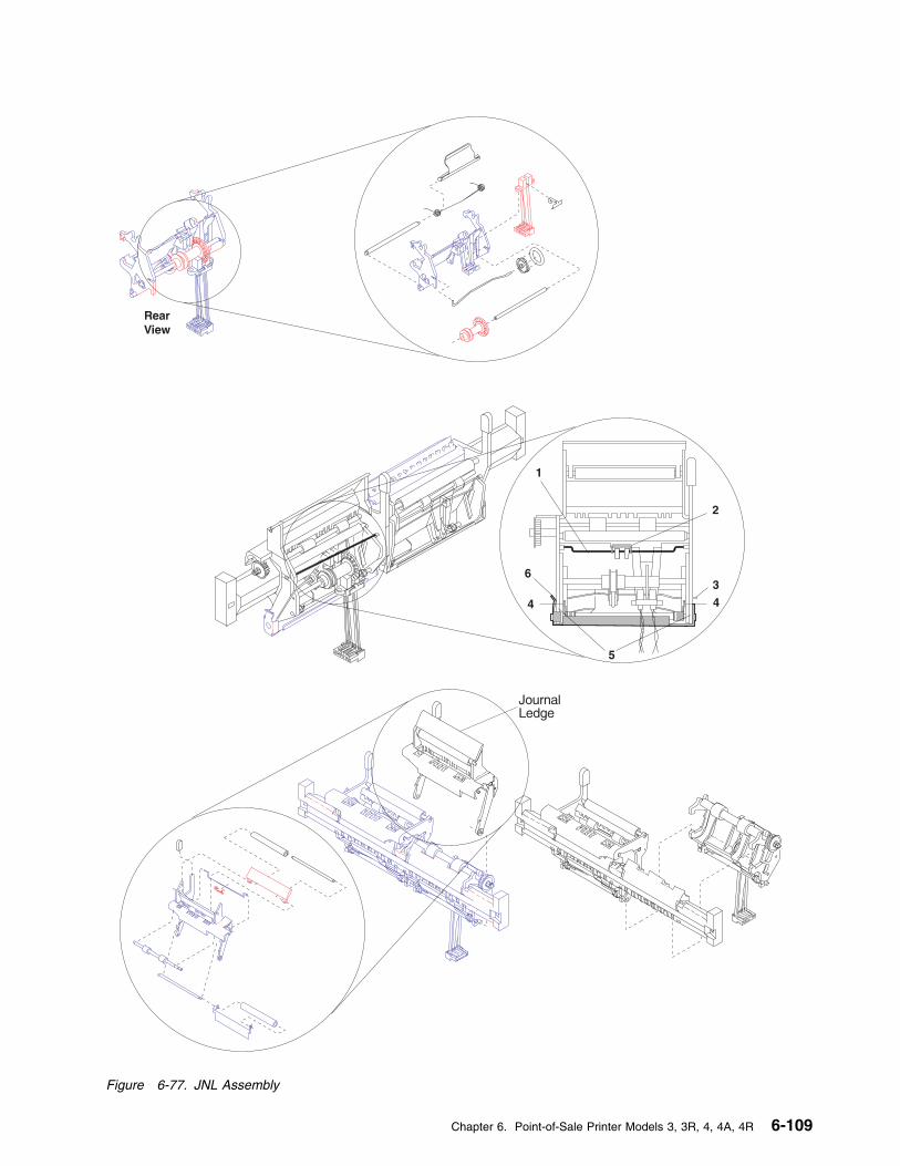
Figure 6-77. JNL Assembly
Chapter 6. Point-of-Sale Printer Models 3, 3R, 4, 4A, 4R 6-109
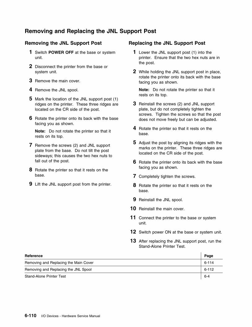
Removing and Replacing the JNL Support Post
Removing the JNL Support Post
1 Switch POWER OFF at the base or systemunit.
2 Disconnect the printer from the base orsystem unit.
3 Remove the main cover.
4 Remove the JNL spool.
5 Mark the location of the JNL support post (1)ridges on the printer. These three ridges arelocated on the CR side of the post.
6 Rotate the printer onto its back with the basefacing you as shown.
Note: Do not rotate the printer so that itrests on its top.
7 Remove the screws (2) and JNL supportplate from the base. Do not tilt the postsideways; this causes the two hex nuts tofall out of the post.
8 Rotate the printer so that it rests on thebase.
9 Lift the JNL support post from the printer.
Replacing the JNL Support Post
1 Lower the JNL support post (1) into theprinter. Ensure that the two hex nuts are inthe post.
2 While holding the JNL support post in place,rotate the printer onto its back with the basefacing you as shown.
Note: Do not rotate the printer so that itrests on its top.
3 Reinstall the screws (2) and JNL supportplate, but do not completely tighten thescrews. Tighten the screws so that the postdoes not move freely but can be adjusted.
4 Rotate the printer so that it rests on thebase.
5 Adjust the post by aligning its ridges with themarks on the printer. These three ridges arelocated on the CR side of the post.
6 Rotate the printer onto its back with the basefacing you as shown.
7 Completely tighten the screws.
8 Rotate the printer so that it rests on thebase.
9 Reinstall the JNL spool.
10 Reinstall the main cover.
11 Connect the printer to the base or systemunit.
12 Switch power ON at the base or system unit.
13 After replacing the JNL support post, run theStand-Alone Printer Test.
Reference Page
Removing and Replacing the Main Cover 6-114
Removing and Replacing the JNL Spool 6-112
Stand-Alone Printer Test 6-4
6-110 I/O Devices - Hardware Service Manual
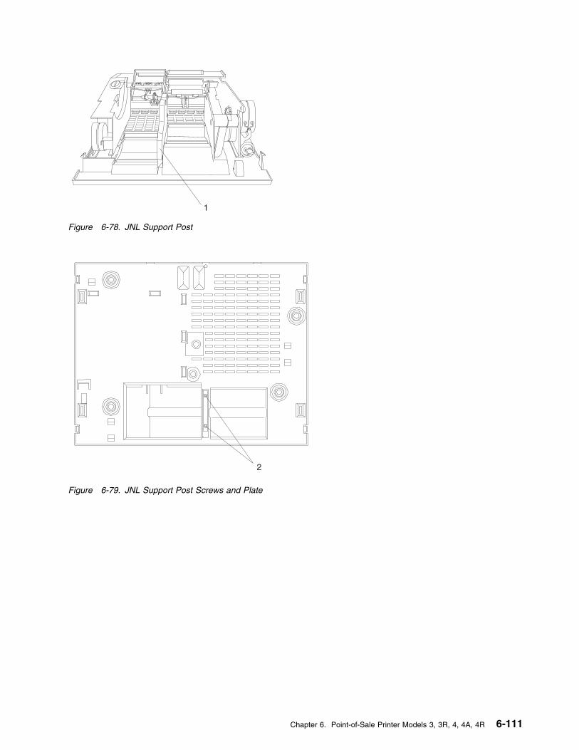
1
Figure 6-78. JNL Support Post
2
Figure 6-79. JNL Support Post Screws and Plate
Chapter 6. Point-of-Sale Printer Models 3, 3R, 4, 4A, 4R 6-111
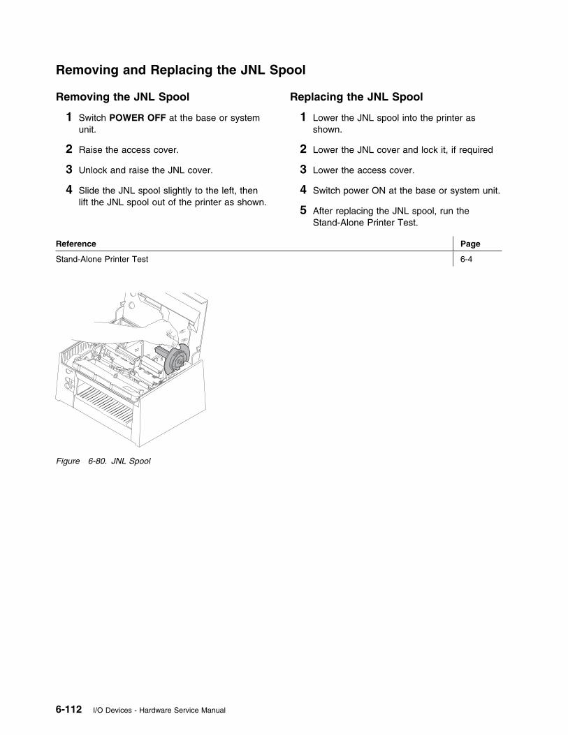
Removing and Replacing the JNL Spool
Removing the JNL Spool
1 Switch POWER OFF at the base or systemunit.
2 Raise the access cover.
3 Unlock and raise the JNL cover.
4 Slide the JNL spool slightly to the left, thenlift the JNL spool out of the printer as shown.
Replacing the JNL Spool
1 Lower the JNL spool into the printer asshown.
2 Lower the JNL cover and lock it, if required
3 Lower the access cover.
4 Switch power ON at the base or system unit.
5 After replacing the JNL spool, run theStand-Alone Printer Test.
Reference Page
Stand-Alone Printer Test 6-4
Figure 6-80. JNL Spool
6-112 I/O Devices - Hardware Service Manual
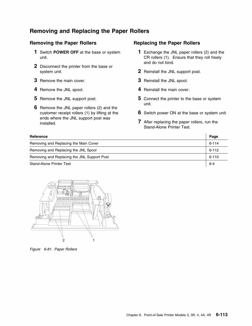
Removing and Replacing the Paper Rollers
Removing the Paper Rollers
1 Switch POWER OFF at the base or systemunit.
2 Disconnect the printer from the base orsystem unit.
3 Remove the main cover.
4 Remove the JNL spool.
5 Remove the JNL support post.
6 Remove the JNL paper rollers (2) and thecustomer receipt rollers (1) by lifting at theends where the JNL support post wasinstalled.
Replacing the Paper Rollers
1 Exchange the JNL paper rollers (2) and theCR rollers (1). Ensure that they roll freelyand do not bind.
2 Reinstall the JNL support post.
3 Reinstall the JNL spool.
4 Reinstall the main cover.
5 Connect the printer to the base or systemunit.
6 Switch power ON at the base or system unit.
7 After replacing the paper rollers, run theStand-Alone Printer Test.
Reference Page
Removing and Replacing the Main Cover 6-114
Removing and Replacing the JNL Spool 6-112
Removing and Replacing the JNL Support Post 6-110
Stand-Alone Printer Test 6-4
12
Figure 6-81. Paper Rollers
Chapter 6. Point-of-Sale Printer Models 3, 3R, 4, 4A, 4R 6-113
Removing and Replacing the Main Cover
Removing the Main Cover
1 Switch POWER OFF at the base or systemunit.
2 Disconnect the printer from the base orsystem unit.
3 Rotate the printer onto its back as shown.
Note: Do not rotate the printer so that itrests on its top.
4 Move the four main cover holding tabs, (1)toward the center of the printer with ascrewdriver to release them as shown.Rotate the printer so that it rests on its base.
5 Remove the main cover from the printer bypivoting the cover onto its left side to preventdamage to the attached cables.
6 Disconnect the top and front keypad cablesand the cover sensor cable from printer cardconnectors J8, J9, and J7, respectively. SeeFigure 6-44 on page 6-69 for an illustrationof the printer card.
Replacing the Main Cover
1 Place the main cover, resting on its left side,to the left of the printer.
2 Connect the top and front keypad cables andthe cover sensor cable to printer cardconnectors J8, J9, and J7, respectively. SeeFigure 6-44 on page 6-69 for an illustrationof the printer card.
3 Align the holding tabs (1) over their slots.Ensure that all of the printer cables arewithin the main cover.
4 Push down on the main cover until the tabslock into place. Ensure that all four tabsengage.
5 Connect the printer to the base or systemunit.
6 Switch power ON at the base or system unit.
7 After replacing the main cover, run theStand-Alone Printer Test.
Reference Page
Stand-Alone Printer Test 6-4
6-114 I/O Devices - Hardware Service Manual
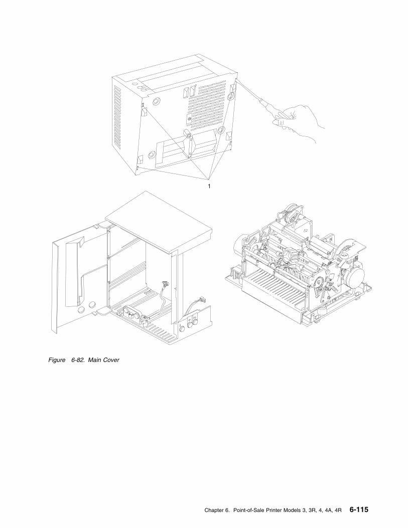
1
Figure 6-82. Main Cover
Chapter 6. Point-of-Sale Printer Models 3, 3R, 4, 4A, 4R 6-115
Removing and Replacing the Platen Assembly
Removing the Platen Assembly
1 Switch POWER OFF at the base or systemunit.
2 Disconnect the printer from the base orsystem unit.
3 Remove the main cover.
4 Remove the JNL spool.
5 Remove the paper cutter.
6 Remove the CR motor gear assembly fromthe printer. Begin at step 5 on page 6-90under Removing the CR Motor GearAssembly.
7 Remove the two platen screws (1), flatwashers, lock washers, and special nutsusing a magnetic tool to prevent thehardware from dropping into the printer.
8 Lift the platen assembly straight up from theprinter.
9 Disconnect the JNL emitter sensor cable(J106) and the MICR cable (J104, if present)from the extension card. See Figure 6-45on page 6-69 for an illustration of theextension card.
Replacing the Platen Assembly
1 Lower the platen assembly into the printer asshown.
Note: Ensure that the rubber O-ring is onits wheel and that the emitter shaft is seatedcorrectly.
2 Connect the JNL emitter sensor cable (J106)and the MICR cable (J104, if present) to theprinter card connector. See Figure 6-45 onpage 6-69 for an illustration of the extensioncard.
3 Push the platen down and push the frame tothe center to maintain the factoryadjustment.
4 Reinstall the two platen screws (1), flatwashers, lock washers, and special nuts.The platen should be seated to the bottomand inside of the side frame compartments.Torque both screws using a torquescrewdriver set at 8.4 inch pounds (0.95Nm).
Note: Ensure that the nut is seatedcorrectly in the side frame. A magnetic toolor needle nose pliers may be required tohold the nut in place while starting the platenscrews.
5 Connect the CR motor gear assembly to theprinter. See steps 2 on page 6-90 and 3 onpage 6-90 under Replacing the CR MotorGear Assembly.
6 Reinstall the paper cutter.
7 Reinstall the JNL spool.
8 Reinstall the main cover.
9 Connect the printer to the base or systemunit.
10 Switch power ON at the base or system unit.
11 After replacing the platen assembly, run theStand-Alone Printer Test.
Reference Page
Removing and Replacing the Main Cover 6-114
Removing and Replacing the JNL Spool 6-112
Removing and Replacing the Paper Cutter 6-87
Stand-Alone Printer Test 6-4
6-116 I/O Devices - Hardware Service Manual
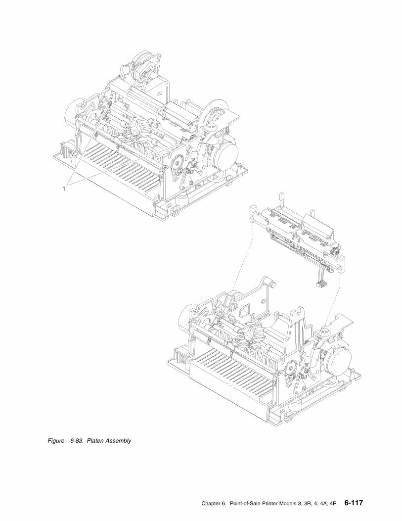
1
Figure 6-83. Platen Assembly
Chapter 6. Point-of-Sale Printer Models 3, 3R, 4, 4A, 4R 6-117

Removing and Replacing the Home Sensor Card
Removing the Home Sensor Card
1 Switch POWER OFF at the base or systemunit.
2 Disconnect the printer from the base orsystem unit.
3 Remove the main cover.
4 Disconnect the sensor cable from the homesensor card. See Figure 6-84 onpage 6-119. The cable is located on the farleft side of the card. Make note of how thecable is routed for reinstallation.
5 Mark the location of the two screws (1) onthe upper forms guide to establish thelocation of the home sensor card.
6 Mark the notch in the edge of the upperforms guide (4) that is closest to the groovein the top edge of the home sensor card.
7 Remove the two screws (1), flat washers,and back-up nut plate.
8 Lift the home sensor card (3) out of theprinter.
Replacing the Home Sensor Card
1 Put the home sensor card (3) into place.
2 Adjust the home sensor card left to rightusing the groove in the card and the markednotch in the upper forms guide (4). Adjustthe home sensor card vertically by locatingthe mounting screws in the same locationthat was marked on the upper forms guide.
Note: To adjust the printing, move thehome sensor card in the direction you wantthe print to move.
3 Reinstall the two screws (1), flat washers,and back-up nut plate. Tighten both screws,making sure the left to right and verticaladjustments are maintained. Torque bothscrews using a torque screwdriver set at 6inch pounds (0.69Nm).
4 Connect the sensor cable (2) to the homesensor card. Route the cable as it wasbefore.
5 Move the print head left and right to ensurethat it does not hit either home sensor.
6 Reinstall the main cover.
7 Connect the printer to the base or systemunit.
8 Switch power ON at the base or system unit.
9 After replacing the home sensor card, runthe Stand-Alone Printer Test.
Reference Page
Removing and Replacing the Main Cover 6-114
Stand-Alone Printer Test 6-4
6-118 I/O Devices - Hardware Service Manual
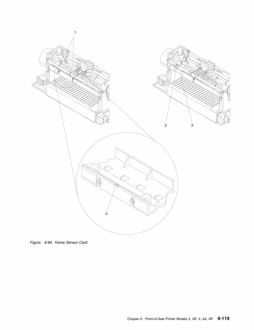
1
2 3
4
Figure 6-84. Home Sensor Card
Chapter 6. Point-of-Sale Printer Models 3, 3R, 4, 4A, 4R 6-119

Removing and Replacing the Transport Assembly
There are two types of transport assemblies. The older style is a helix drive and the newer style is a beltdrive. Printers can be converted from a helix drive to a belt drive but not from a belt drive to a helix drive.
� If you are exchanging a failing helix drive transport assembly with a new helix drive assembly, go to“Removing and Replacing the Helix Drive Transport Assembly.”
� If you are exchanging a failing helix drive transport assembly with a new belt drive assembly, go to“Converting From Helix to Belt Drive Transport Assembly” on page 6-123.
� If you are exchanging a failing belt drive transport assembly with a new belt drive assembly, go to“Removing and Replacing the Belt Drive Transport Assembly” on page 6-123.
� You cannot exchange a failing belt drive transport assembly with a helix drive transport assembly.
Removing and Replacing the Helix Drive Transport Assembly
Removing the Transport Assembly
1 Switch POWER OFF at the base or systemunit.
2 Disconnect the printer from the base orsystem unit.
3 Remove the main cover.
4 Remove the ribbon cartridge.
5 Remove the ribbon drive clutch at the end ofthe transport shaft by prying the gear tabsopen with a screwdriver while pushing thegear out with another screwdriver as shown.See Figure 6-85 on page 6-122.
Note: Ensure that the clutch spring isremoved.
6 Disconnect the transport motor cable fromprinter card connector J4. See Figure 6-44on page 6-69 for an illustration of the printercard.
7 On Models 3R and 4R, remove the DI motorand the cover over the DI gears on the leftside of the printer.
8 Rotate the transport motor clockwise andremove the assembly from the printer.
9 Remove the anti-chatter clip (if present) fromthe helix bearing sleeve on the right sideframe. See Figure 6-85 on page 6-122.
10 Pull the transport assembly through the holein the left side frame, disengaging the helixnut.
11 Move the print head to the center of theprinter, between the CR and JNL stationsand remove the print head.
12 Remove the front carrier shaft by gentlyreleasing one end at a time from the sideframes. See Figure 6-85 on page 6-122.
13 Raise the print head carrier and note theposition of the helix nut in the carrier, thenremove the helix nut.
Replacing the Transport Assembly
1 Move the print head to the center of theprinter, between the CR and JNL stations.Raise the print head carrier and reinstall thehelix nut.
2 Reinstall the front carrier shaft by gentlypressing one end at a time into the sideframes. Ensure that the carrier bushing isinstalled correctly. See Figure 6-85 onpage 6-122.
3 Reinstall the print head and perform the printhead gap adjustment. See “Replacing thePrint Head” on page 6-83.
4 Apply a film of lubricant supplied with thenew assembly to the metal end of thetransport shaft.
5 Place the transport assembly, except for theribbon drive clutch, into the printer andthread the helix through the helix nut.
6 Rotate the transport motor counterclockwiseto attach it to the left side frame.
6-120 I/O Devices - Hardware Service Manual
Note: Be careful not to fold or damage therubber boot on the face of the motor.
7 On Models 3R and 4R, reinstall the DI gearcover and the DI motor.
8 On Models 3R and 4R, reinstall the coverover the DI gears on the left side of theprinter.
9 Apply a film of lubricant supplied with thenew assembly to the outside of the ribbondrive clutch spring, and to both hubs of theribbon drive gear.
10 Push the ribbon drive clutch (spring andgear) onto the transport shaft until it snapsinto place.
11 Snap the anti-chatter clip (if present) backover the helix shaft and bearing sleeve.
12 Move the print head left and right to ensurethat it is functioning correctly.
13 Connect the transport motor cable to printercard connector J4. See Figure 6-44 onpage 6-69 for an illustration of the printercard.
14 Reinstall the ribbon cartridge.
15 Reinstall the main cover.
16 Connect the printer to the base or systemunit.
17 Switch power ON at the base or system unit.
18 After replacing the transport assembly, runthe Stand-Alone Printer Test and perform theprinter adjustments if necessary for propercharacter alignment.
Reference Page
Removing and Replacing the Main Cover 6-114
Stand-Alone printer Test 6-4
Chapter 6. Point-of-Sale Printer Models 3, 3R, 4, 4A, 4R 6-121
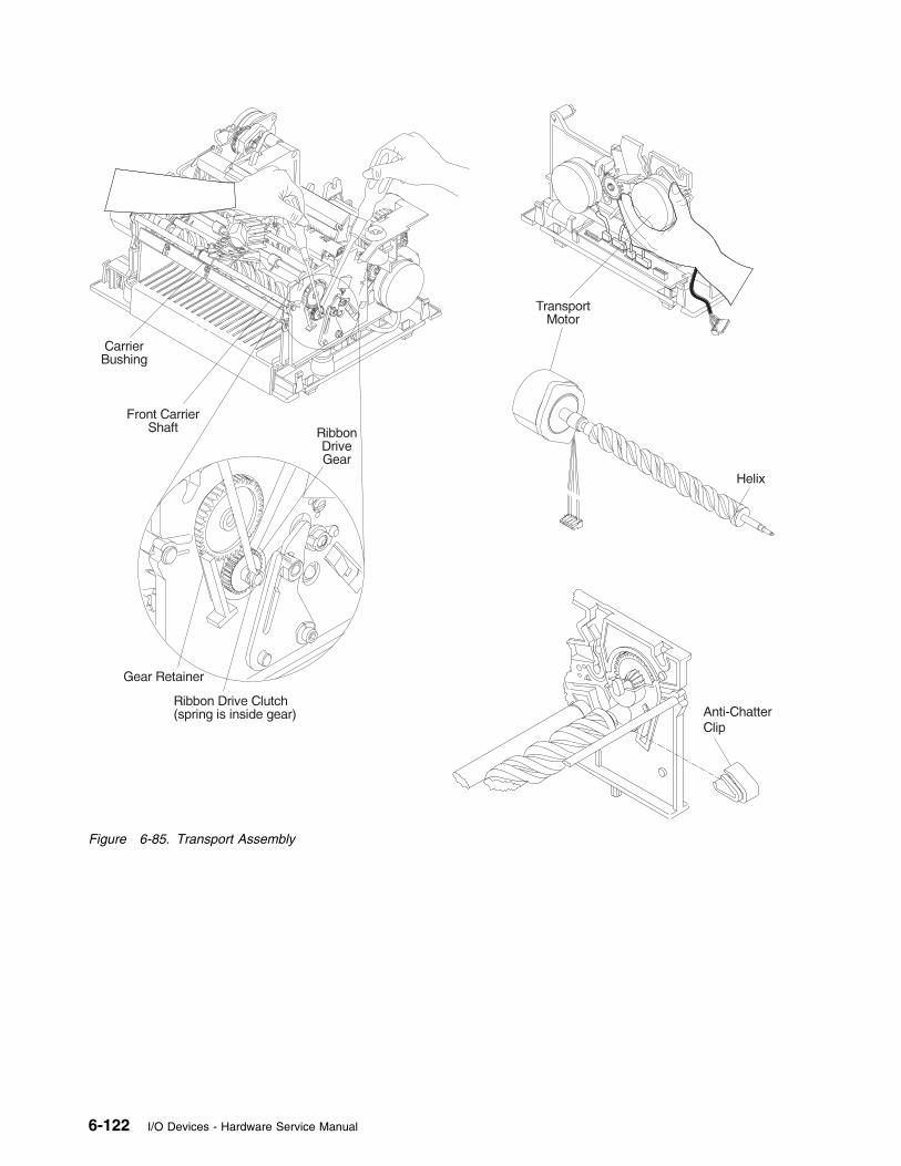
Figure 6-85. Transport Assembly
6-122 I/O Devices - Hardware Service Manual

Converting From Helix to BeltDrive Transport Assembly
1 Remove the helix transport assembly. See“Removing and Replacing the TransportAssembly” on page 6-120.
2 Move the carrier to the center of the printer,between the CR and JNL print stations.
3 Reinstall the front carrier shaft by gentlypressing one end a time into the sideframes. Ensure that the carrier bushing isinstalled correctly.
4 Place the print head into position but do notinstall the screws or other hardware used toretain the print head.
5 Using pliers, remove the motor tabs for thetransport motor on the left side frame. Makesure any excess material does not extendbeyond 0.75mm from the side frame.
6 On Models 3R and 4R, reinstall the coverover the DI gears on the left side of theprinter.
7 The printer is now prepared for the belt drivetransport assembly to be installed. See“Removing and Replacing the Belt DriveTransport Assembly.”
Removing and Replacing the BeltDrive Transport Assembly
Removing the Transport Assembly
1 Switch POWER OFF at the base or systemunit.
2 Disconnect the printer from the base orsystem unit.
3 Remove the main cover.
4 Remove the ribbon cartridge.
5 Disconnect the transport motor cable fromprinter card connector J4. See Figure 6-44on page 6-69 for an illustration of the printercard.
6 Remove the ribbon drive clutch by prying thegear tabs open with a screwdriver while
pushing the gear out with anotherscrewdriver as shown. See Figure 6-85 onpage 6-122.
Note: Ensure that the clutch spring isremoved.
7 Move the print head to the center of theprinter, between the CR and JNL printstations. Remove the 2 screws and otherhardware retaining holding the print head tothe carrier.
8 Push down on the belt near the left side ofthe carrier assembly and move the carrier tothe extreme right side, exposing thetransport assembly mounting hardware onthe left side.
9 Remove the transport assembly clamp, lockwasher, and screw. See Figure 6-86 onpage 6-124.
10 Pull the transport assembly through the holein the left side frame.
11 Move the carrier to the center of the printer,between the CR and JNL print stations.
12 Remove the bushing in the right side framewhere the ribbon drive shaft assembly wasremoved. This can be done by inserting asmall screwdriver into the right side frame topush it out.
Replacing the Transport Assembly
1 Insert the bushing in the right side framewhere the ribbon drive shaft assembly fits.
2 Assemble the transport bevel gear andribbon drive shaft assembly onto thetransport assembly. See Figure 6-86 onpage 6-124.
3 Install the transport assembly into the printerthrough the hole in the left side frame. Besure that the transport assembly is properlylocated at the motor end and that it fitssnugly against the left side frame.
4 Install the clamp, screw, and lockwasher.
5 Apply a thin film of lubricant supplied withthe new assembly to the inside of the ribbondrive clutch spring and to the inside of bothhubs of the drive gear.
Chapter 6. Point-of-Sale Printer Models 3, 3R, 4, 4A, 4R 6-123
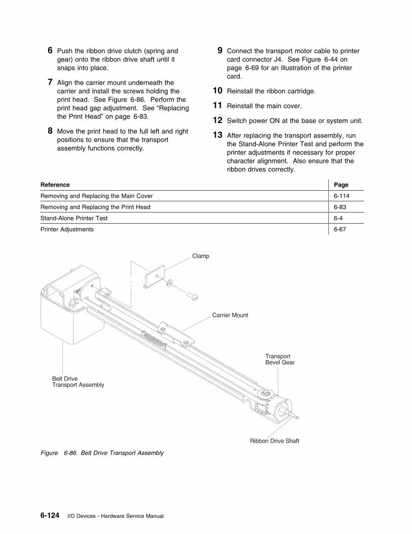
6 Push the ribbon drive clutch (spring andgear) onto the ribbon drive shaft until itsnaps into place.
7 Align the carrier mount underneath thecarrier and install the screws holding theprint head. See Figure 6-86. Perform theprint head gap adjustment. See “Replacingthe Print Head” on page 6-83.
8 Move the print head to the full left and rightpositions to ensure that the transportassembly functions correctly.
9 Connect the transport motor cable to printercard connector J4. See Figure 6-44 onpage 6-69 for an illustration of the printercard.
10 Reinstall the ribbon cartridge.
11 Reinstall the main cover.
12 Switch power ON at the base or system unit.
13 After replacing the transport assembly, runthe Stand-Alone Printer Test and perform theprinter adjustments if necessary for propercharacter alignment. Also ensure that theribbon drives correctly.
Reference Page
Removing and Replacing the Main Cover 6-114
Removing and Replacing the Print Head 6-83
Stand-Alone Printer Test 6-4
Printer Adjustments 6-67
Figure 6-86. Belt Drive Transport Assembly
6-124 I/O Devices - Hardware Service Manual
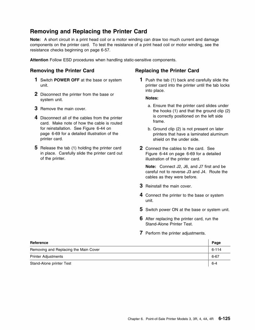
Removing and Replacing the Printer CardNote: A short circuit in a print head coil or a motor winding can draw too much current and damagecomponents on the printer card. To test the resistance of a print head coil or motor winding, see theresistance checks beginning on page 6-57.
Attention Follow ESD procedures when handling static-sensitive components.
Removing the Printer Card
1 Switch POWER OFF at the base or systemunit.
2 Disconnect the printer from the base orsystem unit.
3 Remove the main cover.
4 Disconnect all of the cables from the printercard. Make note of how the cable is routedfor reinstallation. See Figure 6-44 onpage 6-69 for a detailed illustration of theprinter card.
5 Release the tab (1) holding the printer cardin place. Carefully slide the printer card outof the printer.
Replacing the Printer Card
1 Push the tab (1) back and carefully slide theprinter card into the printer until the tab locksinto place.
Notes:
a. Ensure that the printer card slides underthe hooks (1) and that the ground clip (2)is correctly positioned on the left sideframe.
b. Ground clip (2) is not present on laterprinters that have a laminated aluminumshield on the under side.
2 Connect the cables to the card. SeeFigure 6-44 on page 6-69 for a detailedillustration of the printer card.
Note: Connect J2, J6, and J7 first and becareful not to reverse J3 and J4. Route thecables as they were before.
3 Reinstall the main cover.
4 Connect the printer to the base or systemunit.
5 Switch power ON at the base or system unit.
6 After replacing the printer card, run theStand-Alone Printer Test.
7 Perform the printer adjustments.
Reference Page
Removing and Replacing the Main Cover 6-114
Printer Adjustments 6-67
Stand-Alone printer Test 6-4
Chapter 6. Point-of-Sale Printer Models 3, 3R, 4, 4A, 4R 6-125
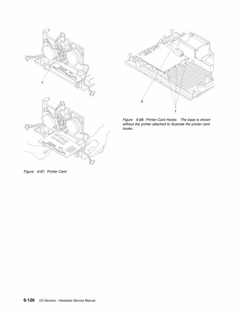
1
Figure 6-87. Printer Card
1
2
Figure 6-88. Printer Card Hooks. The base is shownwithout the printer attached to illustrate the printer cardhooks.
6-126 I/O Devices - Hardware Service Manual
Removing and Replacing the Extension Card
Attention Follow ESD procedures when handling static-sensitive components.
Removing the Extension Card
1 Switch POWER OFF at the base or systemunit.
2 Disconnect the printer from the base orsystem unit.
3 Remove the main cover.
4 Remove the JNL spool.
5 Remove the base.
6 Disconnect all of the cables from theextension card (1). See Figure 6-45 onpage 6-69 for a detailed illustration of theextension card. Make note of how the cableis routed for reinstallation.
7 Release the extension card tabs on eitherside of the printer using a spring hook asshown.
8 Carefully lift the extension card and its cableout of the printer.
Replacing the Extension Card
1 Put the extension card back into place asshown, making sure the tabs on both sideslock into place.
Attention Do not orient the card differentlythan shown to prevent damaging the printer.
2 Connect the cables to the extension card.See Figure 6-45 on page 6-69 for a detailedillustration of the extension card. Route thecables as they were before.
3 Reinstall the base.
4 Reinstall the JNL spool.
5 Reinstall the main cover.
6 Connect the printer to the base or systemunit.
7 Switch power ON at the base or system unit.
8 After replacing the extension card, run theStand-Alone Printer Test.
Reference Page
Removing and Replacing the Main Cover 6-114
Removing and Replacing the JNL Spool 6-112
Removing and Replacing the Base 6-78
Stand-Alone Printer Test 6-4
Chapter 6. Point-of-Sale Printer Models 3, 3R, 4, 4A, 4R 6-127
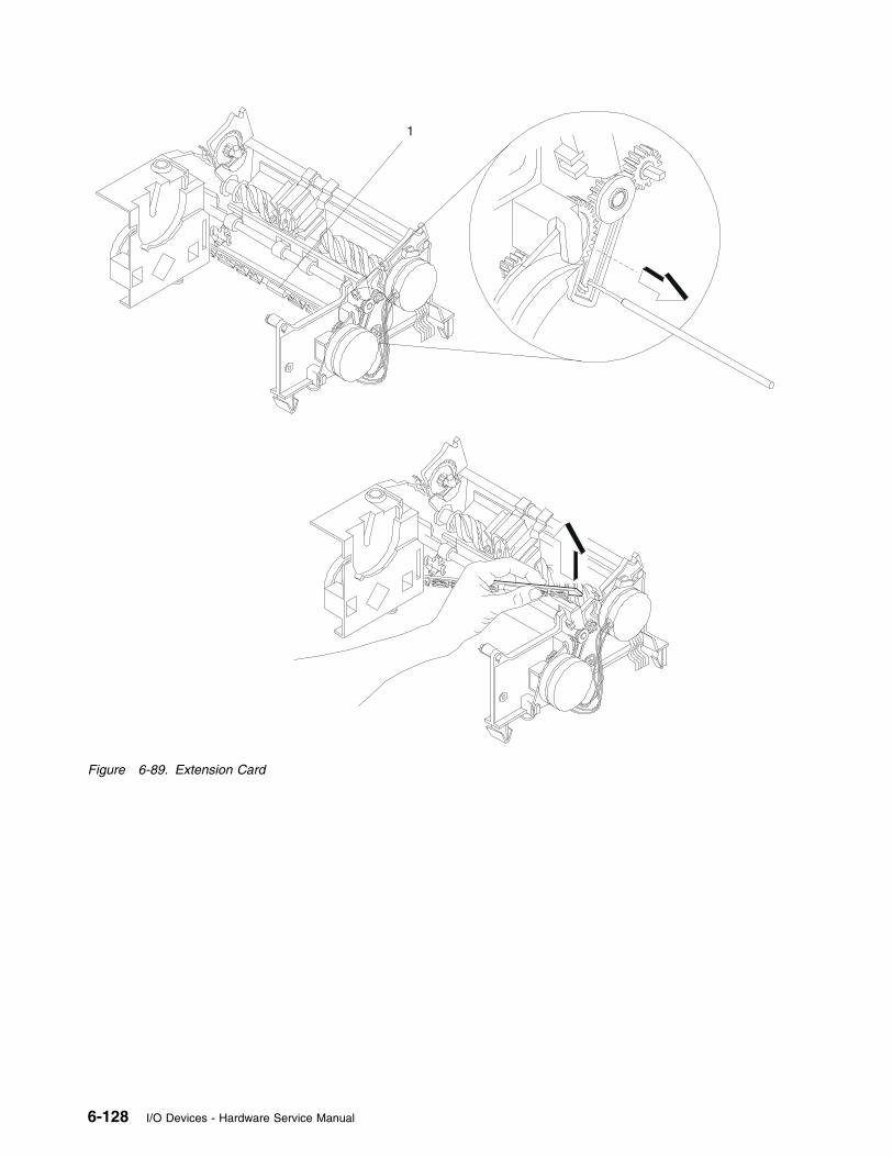
1
Figure 6-89. Extension Card
6-128 I/O Devices - Hardware Service Manual

Chapter 7. 4678 OEM Input/Output Devices
Signature Capture Device (Models A01 and A02)
4678 Models A01 and A02 are signature capture devices consisting of an electromagnetic tablet, interfacecable and pen manufactured by Checkmate Electronics Inc.**. Checkmate 2020 Model A01 uses anRS485 interface cable to attach to device channel ports 4B, 9A, 9B, 9C, or 9/E of an IBM point-of-saleterminal. Checkmate 2020 Model A02 uses an RS232 interface cable to attach to a serial port on apersonal computer or point-of-sale terminal and includes a separate AC adapter that provides +15 V DC tothe tablet.
The pen and ballpoint refill are supply items that are replaced by the user when necessary. The tablet isreplaced when it fails and is returned to the manufacturer for repair.
In this document, Model A01 is referred to as the RS485 interface model. Model A02 is referred to as theRS232 interface model.
Signature Capture Device Preliminary Checks
When the signature capture device fails, perform these preliminary checks:
1 Make sure that the pen cable is securely plugged into the tablet.
2 Make sure that the signature capture device is correctly attached to the POS terminal or personalcomputer.
RS485 model - Attached to socket 4B, 9A, 9B, 9C, or 9/E on the POS terminalRS232 model - Attached to serial port (RS232) of the POS terminal or personal computer.
3 For the RS232 interface model, make sure that the AC adapter is plugged into a known goodelectrical outlet and that its cable is plugged into the RS232 interface cable connector.
4 If the signature capture device is still failing, go to “Signature Capture Device Symptoms” onpage 7-2.
Figure 7-1. RS232 Model
Figure 7-2. RS485 Model
Copyright IBM Corp. 1993, 1995 7-1
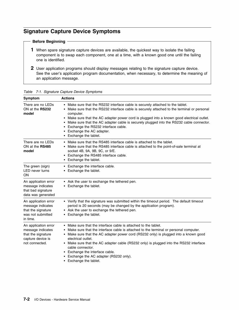
Signature Capture Device Symptoms
Before Beginning
1 When spare signature capture devices are available, the quickest way to isolate the failingcomponent is to swap each component, one at a time, with a known good one until the failingone is identified.
2 User application programs should display messages relating to the signature capture device.See the user’s application program documentation, when necessary, to determine the meaning ofan application message.
Table 7-1. Signature Capture Device Symptoms
Symptom Actions
There are no LEDsON at the RS232model
� Make sure that the RS232 interface cable is securely attached to the tablet.� Make sure that the RS232 interface cable is securely attached to the terminal or personal
computer.� Make sure that the AC adapter power cord is plugged into a known good electrical outlet.� Make sure that the AC adapter cable is securely plugged into the RS232 cable connector.� Exchange the RS232 interface cable.� Exchange the AC adapter.� Exchange the tablet.
There are no LEDsON at the RS485model
� Make sure that the RS485 interface cable is attached to the tablet.� Make sure that the RS485 interface cable is attached to the point-of-sale terminal at
socket 4B, 9A, 9B, 9C, or 9/E.� Exchange the RS485 interface cable.� Exchange the tablet.
The green (sign)LED never turnsON
� Exchange the interface cable.� Exchange the tablet.
An application errormessage indicatesthat bad signaturedata was generated
� Ask the user to exchange the tethered pen.� Exchange the tablet.
An application errormessage indicatesthat the signaturewas not submittedin time.
� Verify that the signature was submitted within the timeout period. The default timeoutperiod is 20 seconds (may be changed by the application program).
� Ask the user to exchange the tethered pen.� Exchange the tablet.
An application errormessage indicatesthat the signaturecapture device isnot connected.
� Make sure that the interface cable is attached to the tablet.� Make sure that the interface cable is attached to the terminal or personal computer.� Make sure that the AC adapter power cord (RS232 only) is plugged into a known good
electrical outlet.� Make sure that the AC adapter cable (RS232 only) is plugged into the RS232 interface
cable connector.� Exchange the interface cable.� Exchange the AC adapter (RS232 only).� Exchange the tablet.
7-2 I/O Devices - Hardware Service Manual

Appendix A. Display and Keyboard Options
Display Options . . . . . . . . . . . . . . . . . . . . . . . . . . . . . . . . . . . . . . . . . . . . . . . . A-2Keyboard Options . . . . . . . . . . . . . . . . . . . . . . . . . . . . . . . . . . . . . . . . . . . . . . . A-4
Copyright IBM Corp. 1993, 1995 A-1

Display Options
A-2 I/O Devices - Hardware Service Manual
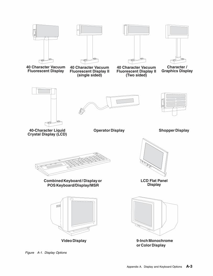
LCD Flat PanelDisplay
40 Character VacuumFluorescent Display
40 Character VacuumFluorescent Display II
(single sided)
40 Character VacuumFluorescent Display II
(Two sided)
40-Character LiquidCrystal Display (LCD)
Character /Graphics Display
Shopper Display
Combined Keyboard / Display orPOS Keyboard/Display/MSR
Operator Display
Video Display 9-Inch Monochromeor Color Display
Figure A-1. Display Options
Appendix A. Display and Keyboard Options A-3
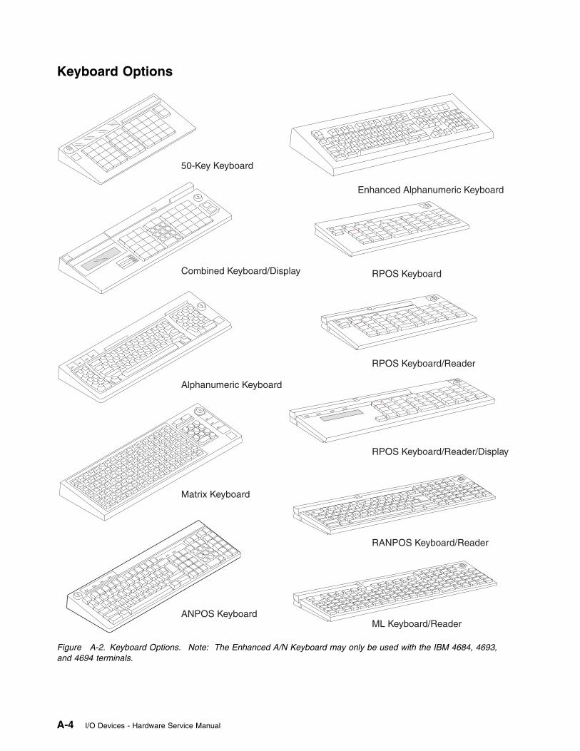
Keyboard Options
Enhanced Alphanumeric Keyboard
RPOS Keyboard
RPOS Keyboard/Reader
RPOS Keyboard/Reader/Display
RANPOS Keyboard/Reader
ML Keyboard/Reader
Matrix Keyboard
Combined Keyboard/Display
50-Key Keyboard
ANPOS Keyboard
Alphanumeric Keyboard
Figure A-2. Keyboard Options. Note: The Enhanced A/N Keyboard may only be used with the IBM 4684, 4693,and 4694 terminals.
A-4 I/O Devices - Hardware Service Manual
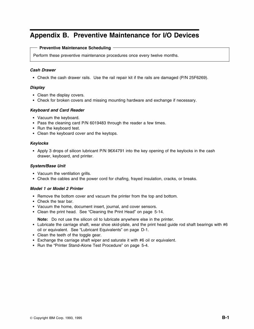
Appendix B. Preventive Maintenance for I/O Devices
Preventive Maintenance Scheduling
Perform these preventive maintenance procedures once every twelve months.
Cash Drawer
� Check the cash drawer rails. Use the rail repair kit if the rails are damaged (P/N 25F6269).
Display
� Clean the display covers.� Check for broken covers and missing mounting hardware and exchange if necessary.
Keyboard and Card Reader
� Vacuum the keyboard.� Pass the cleaning card P/N 6019483 through the reader a few times.� Run the keyboard test.� Clean the keyboard cover and the keytops.
Keylocks
� Apply 3 drops of silicon lubricant P/N 96X4791 into the key opening of the keylocks in the cashdrawer, keyboard, and printer.
System/Base Unit
� Vacuum the ventilation grills.� Check the cables and the power cord for chafing, frayed insulation, cracks, or breaks.
Model 1 or Model 2 Printer
� Remove the bottom cover and vacuum the printer from the top and bottom.� Check the tear bar.� Vacuum the home, document insert, journal, and cover sensors.� Clean the print head. See “Cleaning the Print Head” on page 5-14.
Note: Do not use the silicon oil to lubricate anywhere else in the printer.� Lubricate the carriage shaft, wear shoe skid-plate, and the print head guide rod shaft bearings with #6
oil or equivalent. See “Lubricant Equivalents” on page D-1.� Clean the teeth of the toggle gear.� Exchange the carriage shaft wiper and saturate it with #6 oil or equivalent.� Run the “Printer Stand-Alone Test Procedure” on page 5-4.
Copyright IBM Corp. 1993, 1995 B-1
Models 3, 3R, 4, 4A and 4R Printers
� Clean the dust, fuzz balls, debris, and chad from the printer. This significantly increases the life of theprinter.
� Vacuum dust and debris from the following sensors: – Home sensor– Cover sensor (Model 3 only)– Document insert (DI) upper & lower sensors (journal side)
– Journal sensor
Note: After you clean the DI sensors, the sensor sensitivity needs to be reset. To reset the sensorsensitivity, press the feed up, feed down, and green buttons at the same time. Open the cover andwait for the line feeding to stop. Close the cover.
� Clean the lead screw and black carrier shafts with a clean dry cloth. DO NOT lubricate lead screw orblack carrier shafts.
� Check to see if the print wires are snagging the ribbon. This situation can cause home errors andrequire that the print head be exchanged.
� Check the ribbon drive clutch for proper (one way) operation.� Remove the ribbon and wipe off the ink from the tip of the print head. Ink can collect on the print
head and smudge the forms.� Check and clean the DI rollers using alcohol. Press up or down feed buttons to move the rollers. On
models 3R and 4R you can use the MICR cleaner.� Check the upper forms entry shield for even clearance across the platen face. Make sure the shield is
not trapped between the platen and the print head assembly.� Check that the forms compensation system moves freely by feeding a thick form. The print head
should move back as the feed rollers open up.
Note: Replacing or adjusting the following parts is a factory only repair.� Check blue idler rollers (2) and paper bucket rollers (4) for free movement/rotation. Lubricate with #6
oil.� Clear the debris around the platen rollers.� Oil cutter blade pivots with #6 oil. Wipe off excess oil.� Check that the metal bails, in both the receipt and journal stations that hold the paper are against the
platen, set flush against the platen and paper loads correctly.� On Models 3R and 4R, clean the MICR read head and feed rollers. See “MICR Head and Feed
Rollers Cleaning Procedure” on page 6-9.� On Models 3R and 4R, inspect the MICR pressure pad for wear and damage.� On Models 3R and 4R, exchange the DI gears. Use DI gear kit P/N 73G2598. See “Removing and
Replacing the DI Gears” on page 6-96.� Run the Stand-Alone Printer Test when the PM procedure is complete. See “TEST 4100:
Stand-Alone Printer Test” on page 6-4.
Helpful Hints
� The microcode in the printer allows a change in horizontal and vertical character alignment. Thiscompensates for wear in the printer so if the print line appears to be misaligned, use the appropriatePrinter Adjustment procedure for your terminal. See “Printer Adjustments” on page 6-67.
� If the printer is reporting false home errors, the problem may be the transport motor, helix assembly,and nut.
� False journal out-of-paper conditions, which require the cover to be opened even though paper ispresent, can be caused by the journal slip clutch or the O-ring failure.
B-2 I/O Devices - Hardware Service Manual
Appendix C. Removing and Replacing the Keylock
Removing and Replacing the Lock Insert . . . . . . . . . . . . . . . . . . . . . . . . . . . . . . . . . C-1Removing and Replacing the Blank Lock Insert . . . . . . . . . . . . . . . . . . . . . . . . . . . . . . C-1
Removing and Replacing the Lock Insert
1 See Figure C-1 on page C-2 for identification of the lock pieces.
2 Unlock the keylock before proceeding.
3 Insert the lock installation-removal key fully into the lock insert. See Figure C-4 on page C-3.
Note: There are two installation-removal keys. Use the one that you can insert into the lock insert.The installation-removal keys are shipped with the store controller.
4 Pivot the key slightly downward while pulling the lock insert out of the cylinder until the insert isdisengaged from the cylinder.
5 When replacing the lock insert, it fits all the way into the lock cylinder only when the slot in thebottom of the cylinder and the lug on the end of the insert are both in alignment. If necessary, insertthe aligner tool into the lock cylinder and rotate it until you feel it engage the slot at the bottom of thecylinder. Then turn the aligner tool until the arrow points up. See Figure C-3 on page C-2.
6 Remove the key that came with the new lock insert.
7 Push the brass installation/removal key into the lock insert. Be sure the key is FULLY INSERTED.
8 With the brass installation/removal key still in the lock insert, push the lock insert fully into the lockcylinder.
9 Hold the insert in place with your finger and remove the installation/removal key.
10 Test the lock using the keys that came with the insert to be sure that the lock operates correctly.
Removing and Replacing the Blank Lock InsertNote: The blank lock insert handle is shipped with the store controller.
1 Insert the blank lock insert handle into the blank keylock cylinder. See Figure C-5 on page C-3.
2 Using the blank insert handle, turn the locking screw counter clockwise until the insert can beremoved from the cylinder.
3 When replacing the blank lock insert, the insert has a lug on one end that must be aligned with theslot in the bottom of the lock cylinder. Hold the blank lock insert so that the lug is aligned with theslot.
4 Push the blank lock insert into the empty lock cylinder until it is flush with the top of the lock cylinder.
5 Use the blank lock insert handle to turn the locking screw clockwise until it reaches the bottom of thehole. Do not overtighten.
Copyright IBM Corp. 1993, 1995 C-1

Aligner
Blank LockInstallation Handle
Lock Insert and Keys
BlankLock Insert
Brass Installation/Removal Key
Figure C-1. Lock Pieces
Lock Cylinder
Aligner
Example
Cash Drawer
Figure C-2. Lock Alignment
Keyboard Printer
Cash Drawer System Unit
Arrow Positions
Figure C-3. Aligner Positions
C-2 I/O Devices - Hardware Service Manual
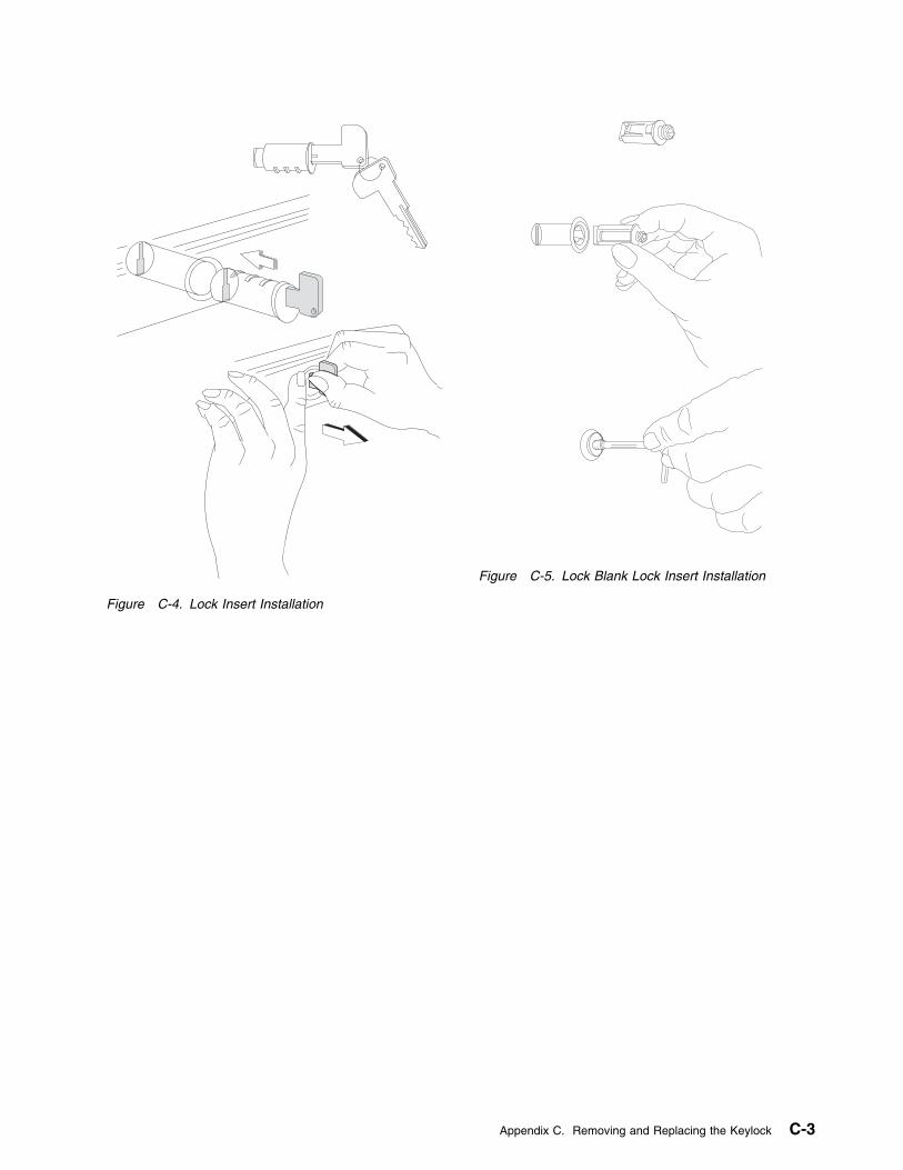
Figure C-4. Lock Insert Installation
Figure C-5. Lock Blank Lock Insert Installation
Appendix C. Removing and Replacing the Keylock C-3

C-4 I/O Devices - Hardware Service Manual
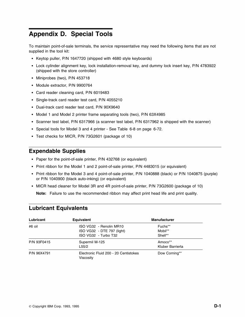
Appendix D. Special Tools
To maintain point-of-sale terminals, the service representative may need the following items that are notsupplied in the tool kit:
� Keytop puller, P/N 1647720 (shipped with 4680 style keyboards)
� Lock cylinder alignment key, lock installation-removal key, and dummy lock insert key, P/N 4783922(shipped with the store controller)
� Miniprobes (two), P/N 453718
� Module extractor, P/N 9900764
� Card reader cleaning card, P/N 6019483
� Single-track card reader test card, P/N 4055210
� Dual-track card reader test card, P/N 90X9640
� Model 1 and Model 2 printer frame separating tools (two), P/N 63X4985
� Scanner test label, P/N 6317966 (a scanner test label, P/N 6317962 is shipped with the scanner)
� Special tools for Model 3 and 4 printer - See Table 6-8 on page 6-72.
� Test checks for MICR, P/N 73G2601 (package of 10)
Expendable Supplies� Paper for the point-of-sale printer, P/N 432768 (or equivalent)
� Print ribbon for the Model 1 and 2 point-of-sale printer, P/N 4483015 (or equivalent)
� Print ribbon for the Model 3 and 4 point-of-sale printer, P/N 1040888 (black) or P/N 1040875 (purple)or P/N 1040900 (black auto-inking) (or equivalent)
� MICR head cleaner for Model 3R and 4R point-of-sale printer, P/N 73G2600 (package of 10)
Note: Failure to use the recommended ribbon may affect print head life and print quality.
Lubricant Equivalents
Lubricant Equivalent Manufacturer
#6 oil ISO VG32 - Renolin MR10ISO VG32 - DTE 797 (light)ISO VG32 - Turbo T32
Fuchs** Mobil** Shell**
P/N 93F0415 Supermil M-125 L55/2
Amoco** Kluber Barrierta
P/N 96X4791 Electronic Fluid 200 - 20 CentistokesViscosity
Dow Corning**
Copyright IBM Corp. 1993, 1995 D-1

D-2 I/O Devices - Hardware Service Manual
Appendix E. Procedures For Model 1 and 2 Printer NotRecommended for Field Personnel
Separating the Upper and Lower Printer Frame Assemblies . . . . . . . . . . . . . . . . . . . . . . E-2Removing and Replacing the Platen Grounding Strap . . . . . . . . . . . . . . . . . . . . . . . . . . E-9
Removing the Platen Grounding Strap . . . . . . . . . . . . . . . . . . . . . . . . . . . . . . . . . E-9Replacing the Platen Grounding Strap . . . . . . . . . . . . . . . . . . . . . . . . . . . . . . . . . E-9
Removing and Replacing the Capacitor . . . . . . . . . . . . . . . . . . . . . . . . . . . . . . . . . E-10Removing the Capacitor . . . . . . . . . . . . . . . . . . . . . . . . . . . . . . . . . . . . . . . . . E-10Replacing the Capacitor . . . . . . . . . . . . . . . . . . . . . . . . . . . . . . . . . . . . . . . . . E-10
Removing and Replacing the Document Insert Backup Roller . . . . . . . . . . . . . . . . . . . . E-11Removing and Replacing the Document Insert Gate . . . . . . . . . . . . . . . . . . . . . . . . . . E-11
Removing the Document Insert Gate . . . . . . . . . . . . . . . . . . . . . . . . . . . . . . . . . E-11Replacing the Document Insert Gate . . . . . . . . . . . . . . . . . . . . . . . . . . . . . . . . . E-11
Removing and Replacing the Document Insert Paper Sensor . . . . . . . . . . . . . . . . . . . . E-13Removing the Document Insert Paper Sensor . . . . . . . . . . . . . . . . . . . . . . . . . . . . E-13Replacing the Document Insert Paper Sensor . . . . . . . . . . . . . . . . . . . . . . . . . . . . E-13
Removing and Replacing the Document Insert/Customer Receipt Motor . . . . . . . . . . . . . . E-13Removing the Document Insert/Customer Receipt Motor . . . . . . . . . . . . . . . . . . . . . . E-13Replacing the Document Insert/Customer Receipt Motor . . . . . . . . . . . . . . . . . . . . . . E-13
Removing and Replacing the Journal Paper Motion Emitter Shaft . . . . . . . . . . . . . . . . . . E-14Removing the Journal Paper Motion Emitter Shaft . . . . . . . . . . . . . . . . . . . . . . . . . E-14Replacing the Journal Paper Motion Emitter Shaft . . . . . . . . . . . . . . . . . . . . . . . . . E-14
Removing and Replacing the Print Head Home Sensor . . . . . . . . . . . . . . . . . . . . . . . . E-15Removing the Print Head Home Sensor . . . . . . . . . . . . . . . . . . . . . . . . . . . . . . . E-15Replacing the Print Head Home Sensor . . . . . . . . . . . . . . . . . . . . . . . . . . . . . . . E-15
Removing and Replacing the Ribbon Drive Shaft . . . . . . . . . . . . . . . . . . . . . . . . . . . . E-16Removing the Ribbon Drive Shaft . . . . . . . . . . . . . . . . . . . . . . . . . . . . . . . . . . . E-16Replacing the Ribbon Drive Shaft . . . . . . . . . . . . . . . . . . . . . . . . . . . . . . . . . . . E-16
Removing and Replacing the Toggle Assembly . . . . . . . . . . . . . . . . . . . . . . . . . . . . . E-18Joining the Upper and Lower Printer Frame Assemblies . . . . . . . . . . . . . . . . . . . . . . . E-18
Copyright IBM Corp. 1993, 1995 E-1

Separating the Upper and Lower Printer Frame Assemblies
Special Frame-Separating Tool
It is not recommended that field service personnel separate the printer frame assemblies. However, insome countries where on-site service is available, this procedure may be done by qualified servicepersonnel. A special frame-separating tool, P/N 63X4985, is used to separate the upper and lowerassemblies.
CAUTION:The edge of the printer's paper guide is sharp.Use care when removing and installing it.
1 Set the printer as shown in Figure E-1
2 Insert a piece of paper in the documentinsert station.
3 Gaining access through the document insertopening, remove the document insert paperguide (1).
4 Lift the guide off the locating pads (2).
5 Move the guide toward the back of theprinter until the holding tabs on the guidecan be pulled out of the openings (3) in theframe.
6 Pull the guide out of the printer.
1
23
Figure E-1. Part 1. Removing the Document Insert Paper Guide
E-2 I/O Devices - Hardware Service Manual
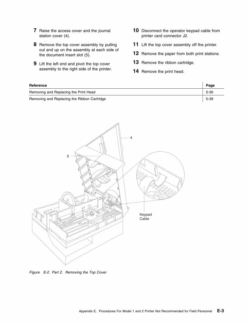
7 Raise the access cover and the journalstation cover (4).
8 Remove the top cover assembly by pullingout and up on the assembly at each side ofthe document insert slot (5).
9 Lift the left end and pivot the top coverassembly to the right side of the printer.
10 Disconnect the operator keypad cable fromprinter card connector J2.
11 Lift the top cover assembly off the printer.
12 Remove the paper from both print stations.
13 Remove the ribbon cartridge.
14 Remove the print head.
Reference Page
Removing and Replacing the Print Head 5-30
Removing and Replacing the Ribbon Cartridge 5-39
KeypadCable
4
5
Figure E-2. Part 2. Removing the Top Cover
Appendix E. Procedures For Model 1 and 2 Printer Not Recommended for Field Personnel E-3
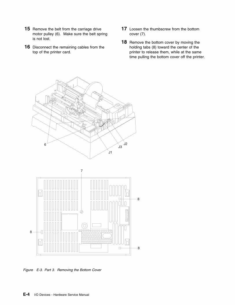
15 Remove the belt from the carriage drivemotor pulley (6). Make sure the belt springis not lost.
16 Disconnect the remaining cables from thetop of the printer card.
17 Loosen the thumbscrew from the bottomcover (7).
18 Remove the bottom cover by moving theholding tabs (8) toward the center of theprinter to release them, while at the sametime pulling the bottom cover off the printer.
J1
J3J26
7
8
8
8
Figure E-3. Part 3. Removing the Bottom Cover
E-4 I/O Devices - Hardware Service Manual
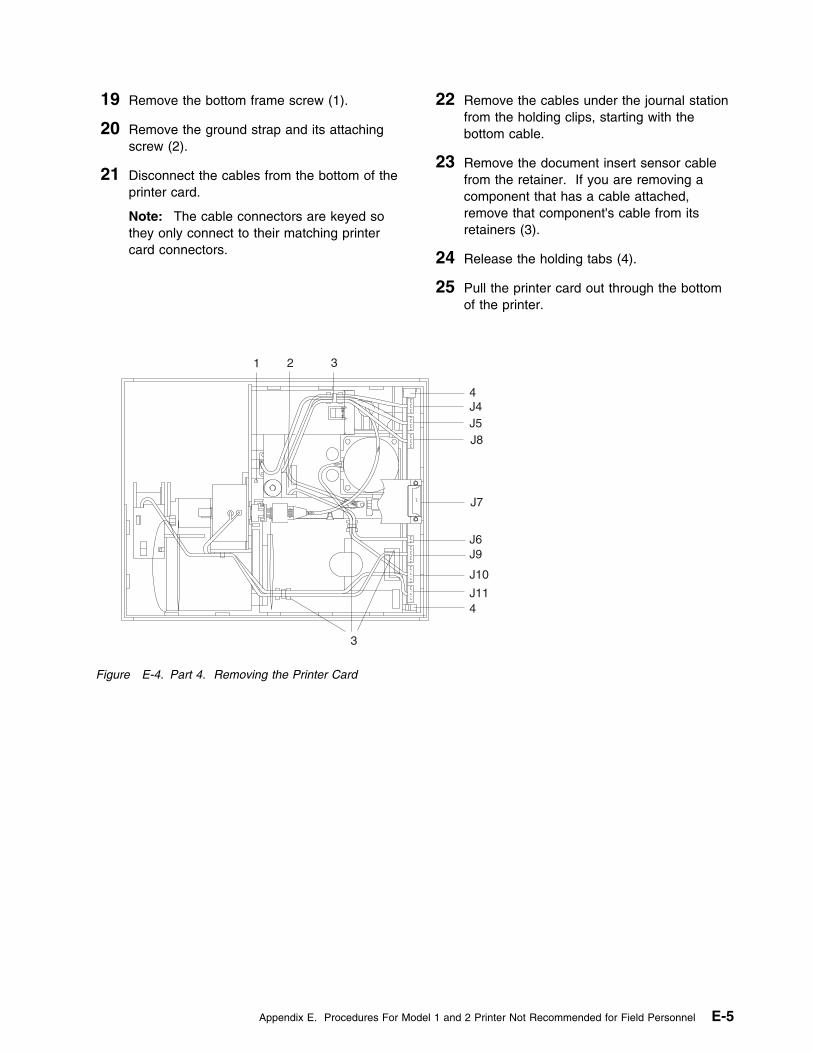
19 Remove the bottom frame screw (1).
20 Remove the ground strap and its attachingscrew (2).
21 Disconnect the cables from the bottom of theprinter card.
Note: The cable connectors are keyed sothey only connect to their matching printercard connectors.
22 Remove the cables under the journal stationfrom the holding clips, starting with thebottom cable.
23 Remove the document insert sensor cablefrom the retainer. If you are removing acomponent that has a cable attached,remove that component's cable from itsretainers (3).
24 Release the holding tabs (4).
25 Pull the printer card out through the bottomof the printer.
J4J5J8
J7
J6J9
J10
J11
1 2 3
4
4
3
Figure E-4. Part 4. Removing the Printer Card
Appendix E. Procedures For Model 1 and 2 Printer Not Recommended for Field Personnel E-5
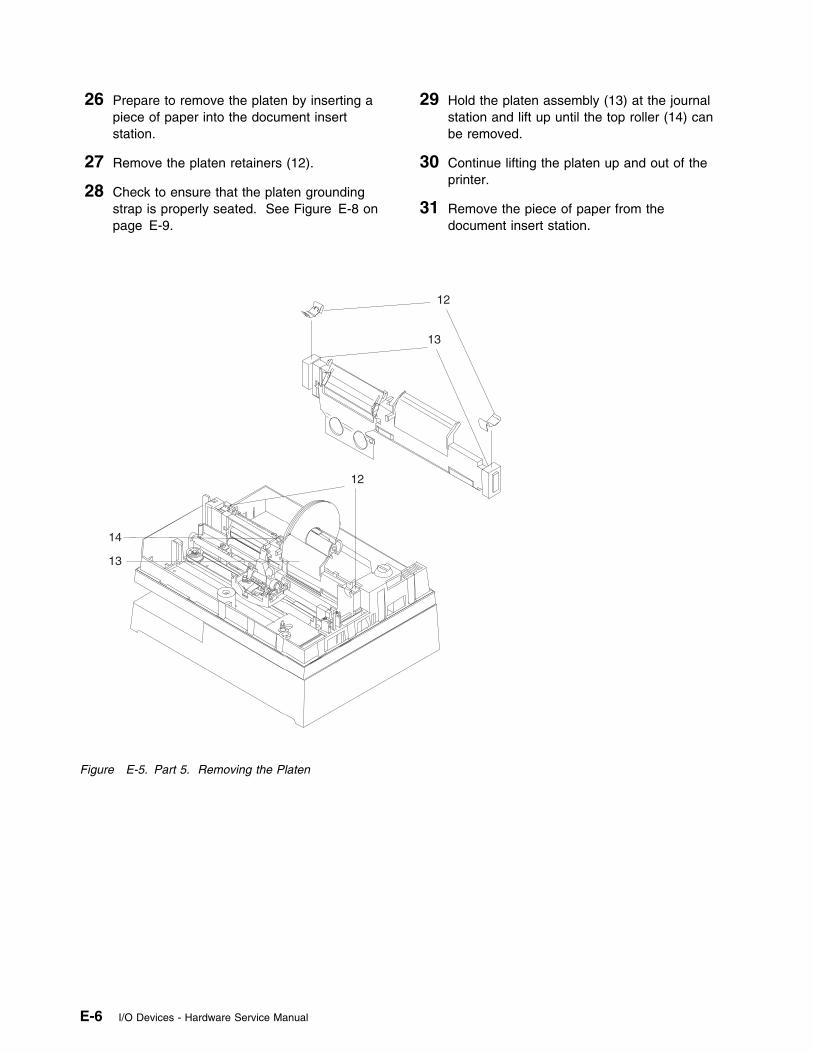
26 Prepare to remove the platen by inserting apiece of paper into the document insertstation.
27 Remove the platen retainers (12).
28 Check to ensure that the platen groundingstrap is properly seated. See Figure E-8 onpage E-9.
29 Hold the platen assembly (13) at the journalstation and lift up until the top roller (14) canbe removed.
30 Continue lifting the platen up and out of theprinter.
31 Remove the piece of paper from thedocument insert station.
12
12
13
13
14
Figure E-5. Part 5. Removing the Platen
E-6 I/O Devices - Hardware Service Manual
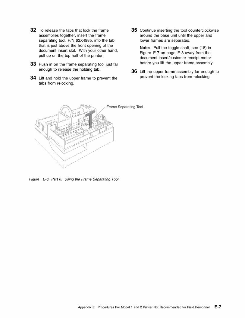
32 To release the tabs that lock the frameassemblies together, insert the frameseparating tool, P/N 63X4985, into the tabthat is just above the front opening of thedocument insert slot. With your other hand,pull up on the top half of the printer.
33 Push in on the frame separating tool just farenough to release the holding tab.
34 Lift and hold the upper frame to prevent thetabs from relocking.
35 Continue inserting the tool counterclockwisearound the base unit until the upper andlower frames are separated.
Note: Pull the toggle shaft, see (18) inFigure E-7 on page E-8 away from thedocument insert/customer receipt motorbefore you lift the upper frame assembly.
36 Lift the upper frame assembly far enough toprevent the locking tabs from relocking.
Frame Separating Tool
Figure E-6. Part 6. Using the Frame Separating Tool
Appendix E. Procedures For Model 1 and 2 Printer Not Recommended for Field Personnel E-7
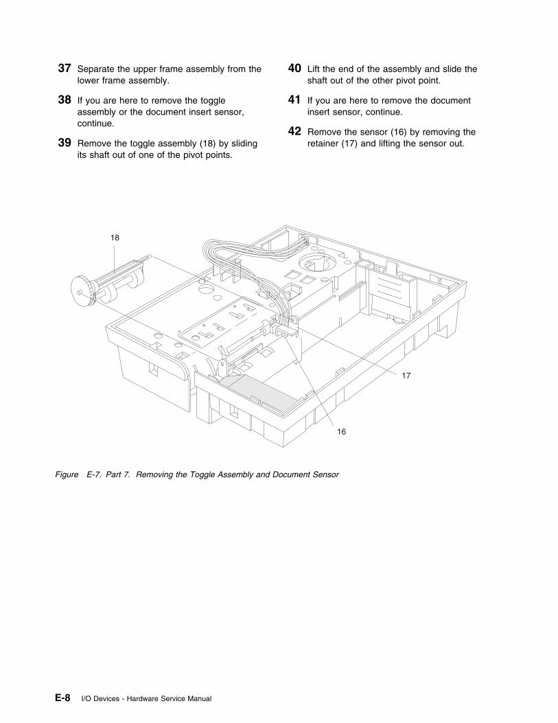
37 Separate the upper frame assembly from thelower frame assembly.
38 If you are here to remove the toggleassembly or the document insert sensor,continue.
39 Remove the toggle assembly (18) by slidingits shaft out of one of the pivot points.
40 Lift the end of the assembly and slide theshaft out of the other pivot point.
41 If you are here to remove the documentinsert sensor, continue.
42 Remove the sensor (16) by removing theretainer (17) and lifting the sensor out.
18
17
16
Figure E-7. Part 7. Removing the Toggle Assembly and Document Sensor
E-8 I/O Devices - Hardware Service Manual
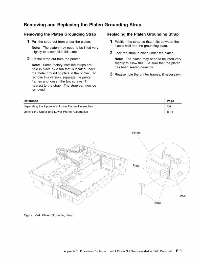
Removing and Replacing the Platen Grounding Strap
Removing the Platen Grounding Strap
1 Pull the strap out from under the platen.
Note: The platen may need to be lifted veryslightly to accomplish this step.
2 Lift the strap out from the printer.
Note: Some factory-installed straps areheld in place by a tab that is located underthe metal grounding plate in the printer. Toremove this version, separate the printerframes and loosen the two screws (1)nearest to the strap. The strap can now beremoved.
Replacing the Platen Grounding Strap
1 Position the strap so that it fits between theplastic wall and the grounding plate.
2 Lock the strap in place under the platen.
Note: The platen may need to be lifted veryslightly to allow this. Be sure that the platenhas been seated correctly.
3 Reassemble the printer frames, if necessary.
Reference Page
Separating the Upper and Lower Frame Assemblies E-2
Joining the Upper and Lower Frame Assemblies E-18
Platen
1
Plate
Wall
Strap
Figure E-8. Platen Grounding Strap
Appendix E. Procedures For Model 1 and 2 Printer Not Recommended for Field Personnel E-9
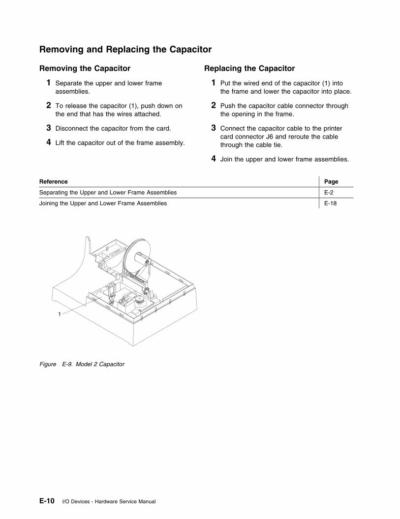
Removing and Replacing the Capacitor
Removing the Capacitor
1 Separate the upper and lower frameassemblies.
2 To release the capacitor (1), push down onthe end that has the wires attached.
3 Disconnect the capacitor from the card.
4 Lift the capacitor out of the frame assembly.
Replacing the Capacitor
1 Put the wired end of the capacitor (1) intothe frame and lower the capacitor into place.
2 Push the capacitor cable connector throughthe opening in the frame.
3 Connect the capacitor cable to the printercard connector J6 and reroute the cablethrough the cable tie.
4 Join the upper and lower frame assemblies.
Reference Page
Separating the Upper and Lower Frame Assemblies E-2
Joining the Upper and Lower Frame Assemblies E-18
1
Figure E-9. Model 2 Capacitor
E-10 I/O Devices - Hardware Service Manual
Removing and Replacing the Document Insert Backup Roller
See “Removing and Replacing the Document Insert Gate.” The document insert backup roller is removedand replaced in this procedure.
Removing and Replacing the Document Insert Gate
Removing the Document Insert Gate
1 Separate the upper and lower frameassemblies.
2 Move the print head carriage to the right endof the frame assembly.
3 Remove the spring (3) from the insert gate(2). See Figure E-10 on page E-12.
4 Push the left end of the backup roller (1)toward the back of the frame. This movesthe end of the backup roller shaft (4) out ofits pivot point.
5 Pull the shaft out of the insert gate.
6 Remove the insert gate from the frameassembly.
7 Remove the backup roller and shaft.
Replacing the Document Insert Gate
1 Insert the backup roller shaft (4) through thebackup roller.
2 Move the print head carriage to the right endof the frame assembly.
3 Put the document insert gate (2) into theframe assembly and locate it as shown inFigure E-10 on page E-12.
4 Locate the backup roller (1) and push theend of the shaft with the flat side into thedocument insert gate.
5 Push the opposite end of the shaft into itspivot point.
6 Replace the spring (3).
7 Join the upper and lower frame assemblies.
Reference Page
Separating the Upper and Lower Frame Assemblies E-2
Joining the Upper and Lower Frame Assemblies E-18
Appendix E. Procedures For Model 1 and 2 Printer Not Recommended for Field Personnel E-11
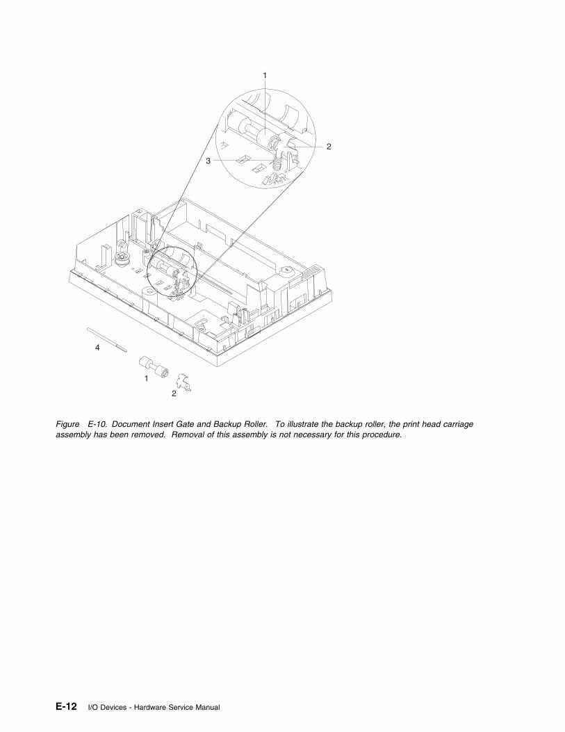
1
2
3
4
1
2
Figure E-10. Document Insert Gate and Backup Roller. To illustrate the backup roller, the print head carriageassembly has been removed. Removal of this assembly is not necessary for this procedure.
E-12 I/O Devices - Hardware Service Manual

Removing and Replacing the Document Insert Paper Sensor
Removing the Document Insert PaperSensor: See “Separating the Upper and LowerPrinter Frame Assemblies” on page E-2. Thedocument insert paper sensor is removed in thisprocedure.
Replacing the Document Insert PaperSensor: See “Joining the Upper and LowerPrinter Frame Assemblies” on page E-18. Thedocument insert paper sensor is replaced in thisprocedure.
Removing and Replacing the Document Insert/Customer Receipt Motor
Removing the DocumentInsert/Customer Receipt Motor
1 Separate the upper and lower frameassemblies. See “Separating the Upper andLower Printer Frame Assemblies” onpage E-2.
2 Move the motor (1) away from the center ofthe frame to release it from its locating pad.
3 Pivot the motor toward you and lift it out ofthe frame.
Replacing the DocumentInsert/Customer Receipt Motor
1 Hold the motor holding clip toward the frameas you put the motor in place.
2 Move the motor toward the center of theframe and into its locating pad.
3 Join the upper and lower frame assemblies.See “Joining the Upper and Lower PrinterFrame Assemblies” on page E-18.
1
Figure E-11. Document Insert/Customer Receipt Motor
Appendix E. Procedures For Model 1 and 2 Printer Not Recommended for Field Personnel E-13
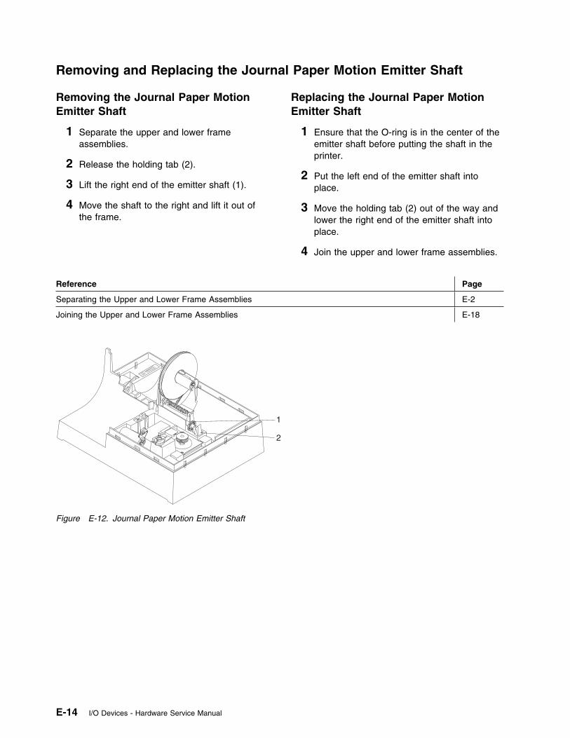
Removing and Replacing the Journal Paper Motion Emitter Shaft
Removing the Journal Paper MotionEmitter Shaft
1 Separate the upper and lower frameassemblies.
2 Release the holding tab (2).
3 Lift the right end of the emitter shaft (1).
4 Move the shaft to the right and lift it out ofthe frame.
Replacing the Journal Paper MotionEmitter Shaft
1 Ensure that the O-ring is in the center of theemitter shaft before putting the shaft in theprinter.
2 Put the left end of the emitter shaft intoplace.
3 Move the holding tab (2) out of the way andlower the right end of the emitter shaft intoplace.
4 Join the upper and lower frame assemblies.
Reference Page
Separating the Upper and Lower Frame Assemblies E-2
Joining the Upper and Lower Frame Assemblies E-18
1
2
Figure E-12. Journal Paper Motion Emitter Shaft
E-14 I/O Devices - Hardware Service Manual
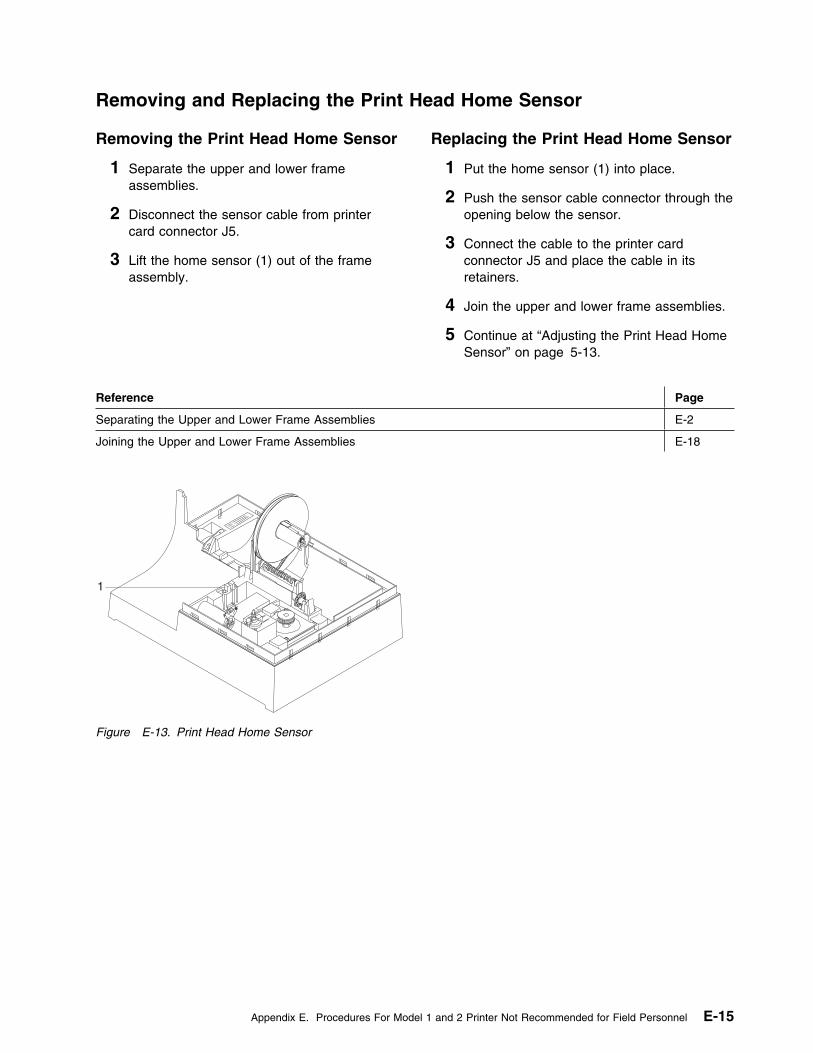
Removing and Replacing the Print Head Home Sensor
Removing the Print Head Home Sensor
1 Separate the upper and lower frameassemblies.
2 Disconnect the sensor cable from printercard connector J5.
3 Lift the home sensor (1) out of the frameassembly.
Replacing the Print Head Home Sensor
1 Put the home sensor (1) into place.
2 Push the sensor cable connector through theopening below the sensor.
3 Connect the cable to the printer cardconnector J5 and place the cable in itsretainers.
4 Join the upper and lower frame assemblies.
5 Continue at “Adjusting the Print Head HomeSensor” on page 5-13.
Reference Page
Separating the Upper and Lower Frame Assemblies E-2
Joining the Upper and Lower Frame Assemblies E-18
1
Figure E-13. Print Head Home Sensor
Appendix E. Procedures For Model 1 and 2 Printer Not Recommended for Field Personnel E-15
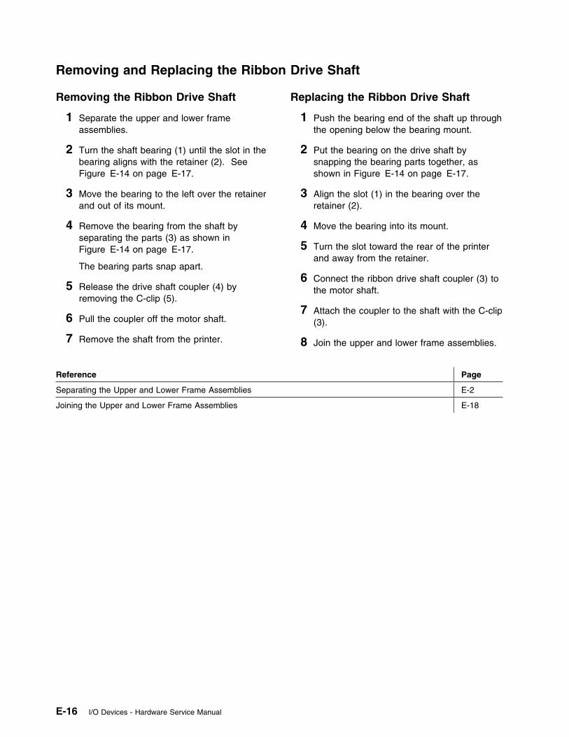
Removing and Replacing the Ribbon Drive Shaft
Removing the Ribbon Drive Shaft
1 Separate the upper and lower frameassemblies.
2 Turn the shaft bearing (1) until the slot in thebearing aligns with the retainer (2). SeeFigure E-14 on page E-17.
3 Move the bearing to the left over the retainerand out of its mount.
4 Remove the bearing from the shaft byseparating the parts (3) as shown inFigure E-14 on page E-17.
The bearing parts snap apart.
5 Release the drive shaft coupler (4) byremoving the C-clip (5).
6 Pull the coupler off the motor shaft.
7 Remove the shaft from the printer.
Replacing the Ribbon Drive Shaft
1 Push the bearing end of the shaft up throughthe opening below the bearing mount.
2 Put the bearing on the drive shaft bysnapping the bearing parts together, asshown in Figure E-14 on page E-17.
3 Align the slot (1) in the bearing over theretainer (2).
4 Move the bearing into its mount.
5 Turn the slot toward the rear of the printerand away from the retainer.
6 Connect the ribbon drive shaft coupler (3) tothe motor shaft.
7 Attach the coupler to the shaft with the C-clip(3).
8 Join the upper and lower frame assemblies.
Reference Page
Separating the Upper and Lower Frame Assemblies E-2
Joining the Upper and Lower Frame Assemblies E-18
E-16 I/O Devices - Hardware Service Manual
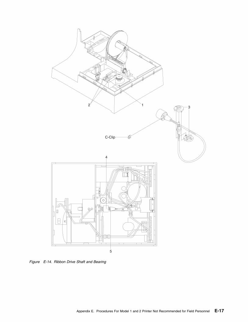
5
4
C-Clip
312
Figure E-14. Ribbon Drive Shaft and Bearing
Appendix E. Procedures For Model 1 and 2 Printer Not Recommended for Field Personnel E-17
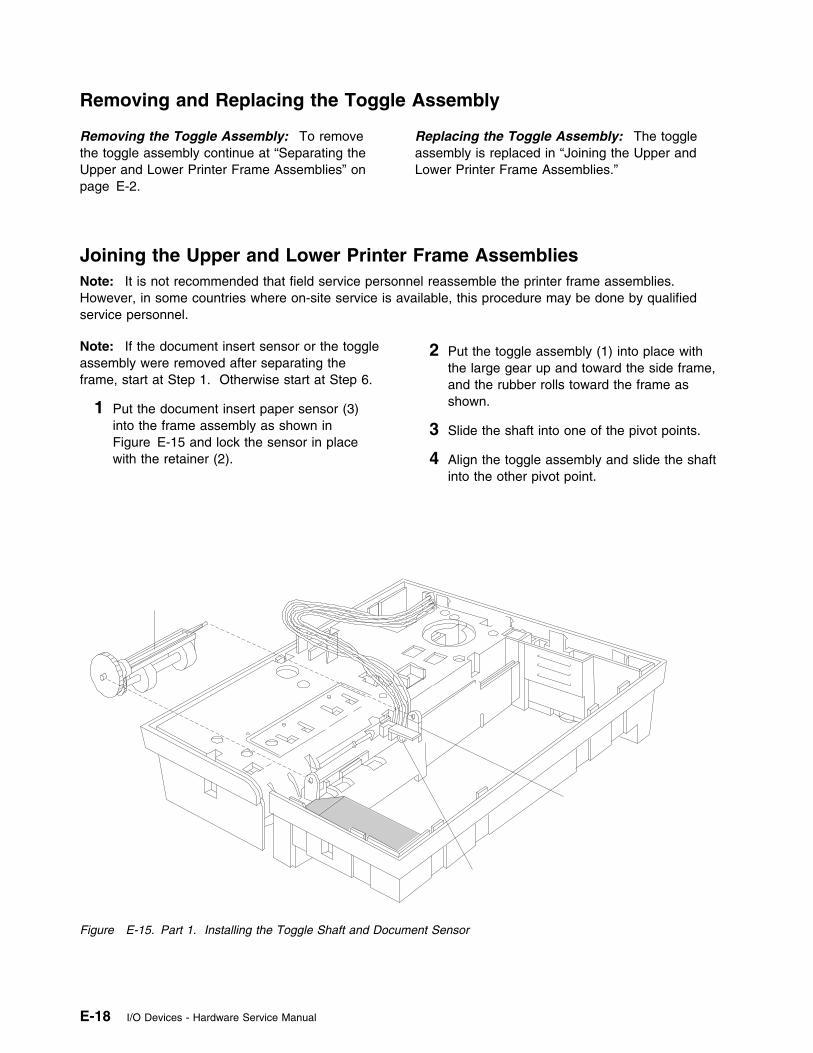
Removing and Replacing the Toggle Assembly
Removing the Toggle Assembly: To removethe toggle assembly continue at “Separating theUpper and Lower Printer Frame Assemblies” onpage E-2.
Replacing the Toggle Assembly: The toggleassembly is replaced in “Joining the Upper andLower Printer Frame Assemblies.”
Joining the Upper and Lower Printer Frame AssembliesNote: It is not recommended that field service personnel reassemble the printer frame assemblies.However, in some countries where on-site service is available, this procedure may be done by qualifiedservice personnel.
Note: If the document insert sensor or the toggleassembly were removed after separating theframe, start at Step 1. Otherwise start at Step 6.
1 Put the document insert paper sensor (3)into the frame assembly as shown inFigure E-15 and lock the sensor in placewith the retainer (2).
2 Put the toggle assembly (1) into place withthe large gear up and toward the side frame,and the rubber rolls toward the frame asshown.
3 Slide the shaft into one of the pivot points.
4 Align the toggle assembly and slide the shaftinto the other pivot point.
Figure E-15. Part 1. Installing the Toggle Shaft and Document Sensor
E-18 I/O Devices - Hardware Service Manual
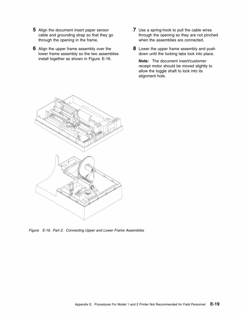
5 Align the document insert paper sensorcable and grounding strap so that they gothrough the opening in the frame.
6 Align the upper frame assembly over thelower frame assembly so the two assembliesinstall together as shown in Figure E-16.
7 Use a spring-hook to pull the cable wiresthrough the opening so they are not pinchedwhen the assemblies are connected.
8 Lower the upper frame assembly and pushdown until the locking tabs lock into place.
Note: The document insert/customerreceipt motor should be moved slightly toallow the toggle shaft to lock into itsalignment hole.
Figure E-16. Part 2. Connecting Upper and Lower Frame Assemblies
Appendix E. Procedures For Model 1 and 2 Printer Not Recommended for Field Personnel E-19
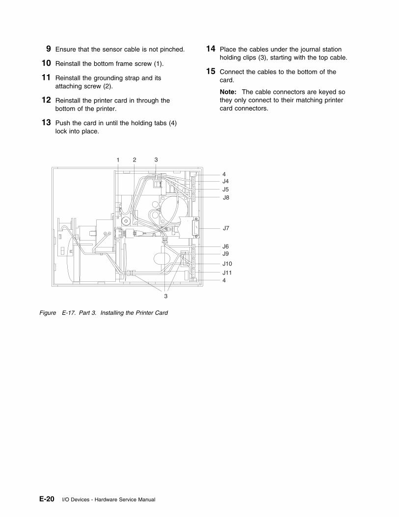
9 Ensure that the sensor cable is not pinched.
10 Reinstall the bottom frame screw (1).
11 Reinstall the grounding strap and itsattaching screw (2).
12 Reinstall the printer card in through thebottom of the printer.
13 Push the card in until the holding tabs (4)lock into place.
14 Place the cables under the journal stationholding clips (3), starting with the top cable.
15 Connect the cables to the bottom of thecard.
Note: The cable connectors are keyed sothey only connect to their matching printercard connectors.
J4J5J8
J7
J6J9
J10
J11
1 2 3
4
4
3
Figure E-17. Part 3. Installing the Printer Card
E-20 I/O Devices - Hardware Service Manual
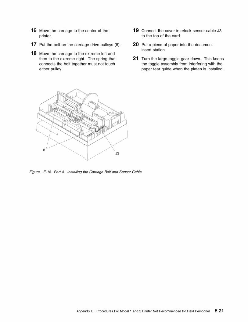
16 Move the carriage to the center of theprinter.
17 Put the belt on the carriage drive pulleys (8).
18 Move the carriage to the extreme left andthen to the extreme right. The spring thatconnects the belt together must not toucheither pulley.
19 Connect the cover interlock sensor cable J3to the top of the card.
20 Put a piece of paper into the documentinsert station.
21 Turn the large toggle gear down. This keepsthe toggle assembly from interfering with thepaper tear guide when the platen is installed.
J38
Figure E-18. Part 4. Installing the Carriage Belt and Sensor Cable
Appendix E. Procedures For Model 1 and 2 Printer Not Recommended for Field Personnel E-21
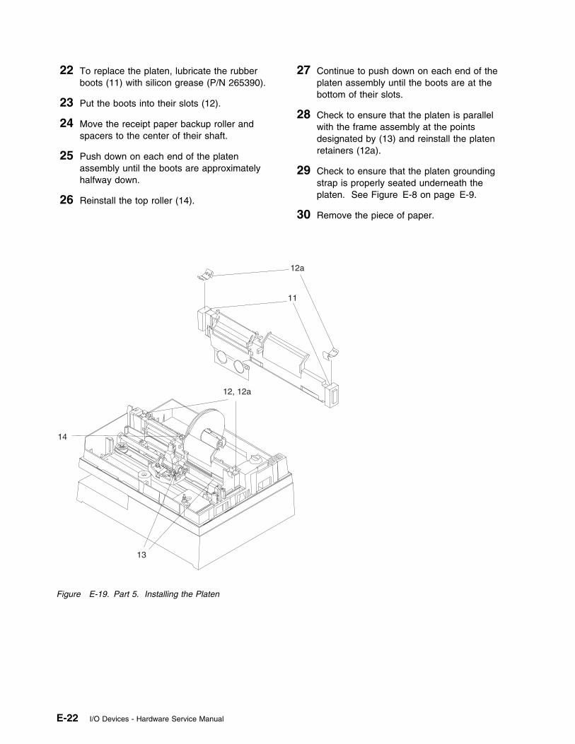
22 To replace the platen, lubricate the rubberboots (11) with silicon grease (P/N 265390).
23 Put the boots into their slots (12).
24 Move the receipt paper backup roller andspacers to the center of their shaft.
25 Push down on each end of the platenassembly until the boots are approximatelyhalfway down.
26 Reinstall the top roller (14).
27 Continue to push down on each end of theplaten assembly until the boots are at thebottom of their slots.
28 Check to ensure that the platen is parallelwith the frame assembly at the pointsdesignated by (13) and reinstall the platenretainers (12a).
29 Check to ensure that the platen groundingstrap is properly seated underneath theplaten. See Figure E-8 on page E-9.
30 Remove the piece of paper.
12a
11
12, 12a
14
13
Figure E-19. Part 5. Installing the Platen
E-22 I/O Devices - Hardware Service Manual
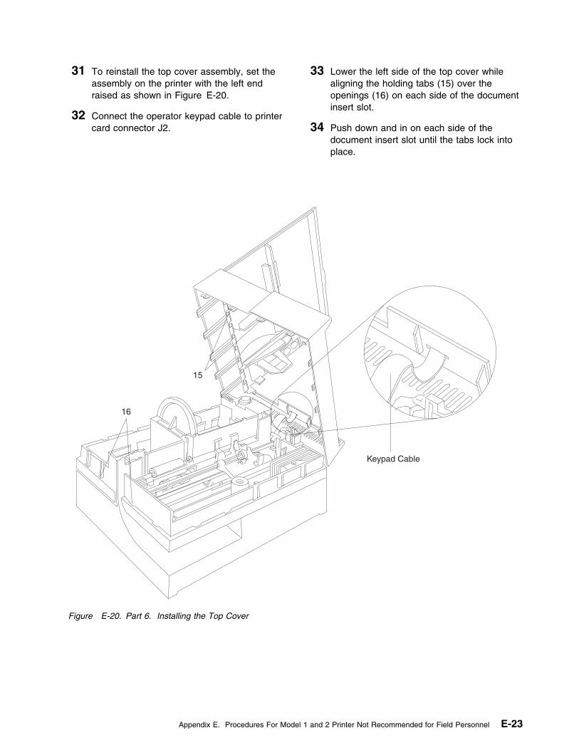
31 To reinstall the top cover assembly, set theassembly on the printer with the left endraised as shown in Figure E-20.
32 Connect the operator keypad cable to printercard connector J2.
33 Lower the left side of the top cover whilealigning the holding tabs (15) over theopenings (16) on each side of the documentinsert slot.
34 Push down and in on each side of thedocument insert slot until the tabs lock intoplace.
Keypad Cable
15
16
Figure E-20. Part 6. Installing the Top Cover
Appendix E. Procedures For Model 1 and 2 Printer Not Recommended for Field Personnel E-23
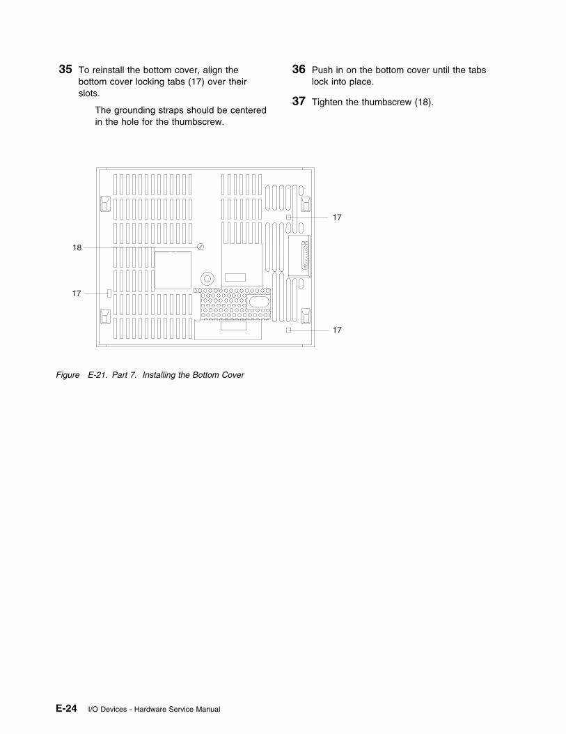
35 To reinstall the bottom cover, align thebottom cover locking tabs (17) over theirslots.
The grounding straps should be centeredin the hole for the thumbscrew.
36 Push in on the bottom cover until the tabslock into place.
37 Tighten the thumbscrew (18).
17
17
17
18
Figure E-21. Part 7. Installing the Bottom Cover
E-24 I/O Devices - Hardware Service Manual
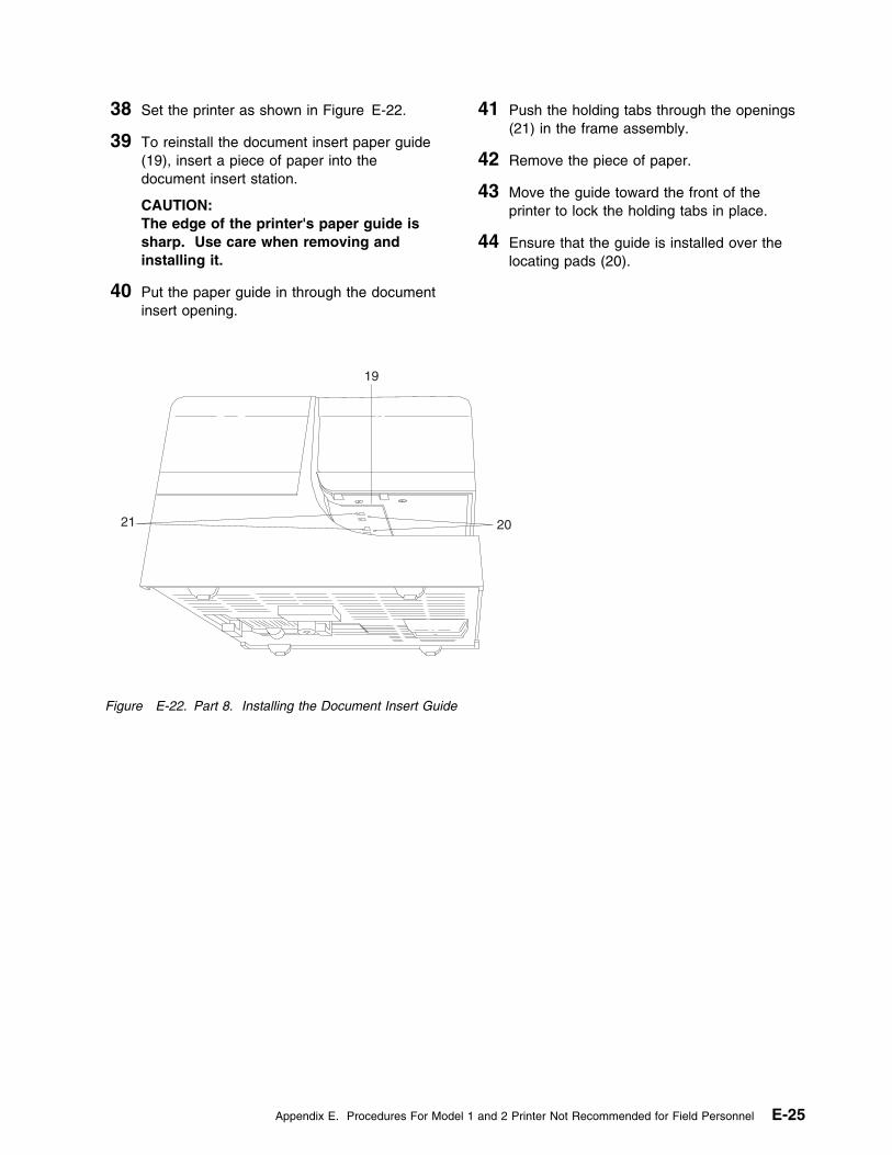
38 Set the printer as shown in Figure E-22.
39 To reinstall the document insert paper guide(19), insert a piece of paper into thedocument insert station.
CAUTION:The edge of the printer's paper guide issharp. Use care when removing andinstalling it.
40 Put the paper guide in through the documentinsert opening.
41 Push the holding tabs through the openings(21) in the frame assembly.
42 Remove the piece of paper.
43 Move the guide toward the front of theprinter to lock the holding tabs in place.
44 Ensure that the guide is installed over thelocating pads (20).
19
21 20
Figure E-22. Part 8. Installing the Document Insert Guide
Appendix E. Procedures For Model 1 and 2 Printer Not Recommended for Field Personnel E-25

E-26 I/O Devices - Hardware Service Manual
Index
Numerics40-character alphanumeric display
cleaning and replacing the lens 3-244680 library x4683, testing input/output devices 1-14683/4684 library x4690 library x4693 library x4693, testing input/output devices 1-150-key keyboard
messages 4-3removing and replacing components 4-7symptoms 4-5
Aadjusting the model 2 printer
home sensor flag 5-13print head cam 5-12
alphanumeric keyboardmessages 4-3removing and replacing components 4-9symptoms 4-5
ANPOS keyboardmessages 4-3removing and replacing components 4-11symptoms 4-5
Bblank lock insert, removing and replacing C-1
Ccard reader (MSR)
cleaning card D-1messages 4-3symptoms 4-5test card D-1
cash drawer (dark gray)messages 2-9removals and replacements
card assembly 2-14cash drawer 2-11cash drawer cam 2-14cash drawer pawl 2-14keylock assembly 2-16latch assembly 2-13slide assembly 2-12top cover 2-12
repairing 2-8, 2-16symptoms 2-9
cash drawer (light gray)messages 2-3removals and replacements
cam 2-7cash drawer assembly 2-4keylock assembly 2-8latch and sensor assembly 2-6slide assembly 2-6top cover 2-5
repairing 2-3symptoms 2-3
combined keyboard/displaymessages 4-3removing and replacing components 4-18symptoms 4-5
compact cash drawer integration cover 2-25
Ddiagnosing a problem
See isolating a problemdisplay options A-2displays
Eelectronic discharge (ESD) viielectronic emission notices viESD (electrostatic discharge)
attention 2-1, 4-1, 5-1, 6-2expendable supplies
MICR head cleaner D-1point-of-sale printer paper D-1point-of-sale printer ribbon cartridge D-1
FFCC information viflat panel display
cable 3-8filler panel 3-8messages 3-3removal and replacement procedures 3-6sleep control 3-4sleep mode 3-5symptoms 3-5
Ggeneral safety considerations vi
Copyright IBM Corp. 1993, 1995 X-1
Hhead cleaning (model 1 or 2 printer) 5-14head cleaning procedure, MICR printer 6-9
Iisolating a problem
cash drawer (compact) 2-16cash drawer (dark gray) 2-8cash drawer (light gray) 2-3keyboards 4-1model 1 or 2 printer 5-8printer (models 1 and 2) 5-1printer (models 3 and 4) 6-1start here 1-1
Jjournal paper replacement (model 1 or 2 printer) 5-46
Kkeyboards
identification A-4messages 4-3optional A-4removing and replacing components 4-14repairing 4-1
keylock, removing and replacing C-1
Llibraries, 4693/4683/4684/4680/4690 xlock insert, removing C-1
Mmaintenance analysis procedure
printer (model 3 and model 4)CR motor resistance check 6-57CR or JNL paper advances continuously 6-13CR paper does not advance 6-16CR paper jam 6-19CR station is overprinting 6-21DI motor resistance check 6-59DI paper advances continuously 6-22DI station does not feed document correctly or is
overprinting 6-23home error 6-27JNL motor resistance check 6-60JNL paper does not advance 6-29JNL station is overprinting 6-35JNL station not printing 6-32MICR fails to read correctly 6-36paper cutter does not cut properly 6-14paper cutter motor resistance check 6-58power problem 6-39
maintenance analysis procedure (continued)printer (model 3 and model 4) (continued)
print head resistance check 6-61printed character is light 6-43printed character is smudged 6-47printed character missing one or more dot
row 6-45printer indicator light always on or comes on
randomly 6-48printer indicator light not on 6-49printer indicator light not on when document
inserted 6-51printer not printing any character 6-53ribbon damaged by printer 6-55ribbon does not advance 6-56stand-alone MICR test 6-8stand-alone printer test 6-4transport motor resistance check 6-62
MAPSee maintenance analysis procedure
messages 1-2card reader 4-3cash drawer (dark gray) 2-9cash drawer (light gray) 2-3flat panel display 3-3keyboard 4-3printer, model 1 and 2 5-6printer, model 3 and 4 6-10
MICR (magnetic ink character reader)head cleaning procedure 6-9stand-alone MICR test 6-8
Ooptional displays A-2optional keyboards A-4
Ppaper (model 1 or 2 printer) 5-44preventive maintenance B-1
cash drawer B-1display B-1keyboard B-1keylocks B-1model 1 or 2 printer B-1model 3 or 4 printer B-2system/base unit B-1
print head (model 2 printer)removing 5-30replacing 5-31
print head cleaning (model 1 or 2 printer) 5-14printer (model 1 and model 2)
adjusting the home sensor flag 5-13adjusting the print head cam 5-12cleaning the print head 5-14
X-2 I/O Devices - Hardware Service Manual
printer (model 1 and model 2) (continued)journal station paper 5-46messages 5-6removals and replacements
access cover 5-16bottom cover 5-17capacitor E-10connecting the upper and lower frame E-18cover-interlock sensor 5-18document insert backup roller E-11document insert gate E-11document insert paper guide 5-19document insert paper sensor E-13document insert/receipt motor E-13journal cover 5-20journal drive belt 5-20journal motor pulley 5-20journal paper motion emitter sensor 5-21journal paper motion emitter shaft E-14journal spool and clutch 5-24journal/ribbon motor 5-22keylock 5-26keypad 5-27platen and paper tear guide 5-28platen grounding strap E-9print head 5-30print head carriage 5-34print head carriage and shaft 5-32print head carriage drive belt 5-36print head carriage motor 5-36print head home sensor E-15printer card 5-38receipt paper backup roller 5-42ribbon cartridge 5-39ribbon drive shaft E-16separating the upper and lower frame E-2toggle assembly E-18top cover 5-43
replacementscustomer receipt paper 5-44
sensor check 5-48stand-alone test procedure 5-4symptom 5-8
printer (model 3 and model 4)adjustment
using the 4680/4690 operating system 6-67using the reference diskette 6-67
maintenance analysis procedure (MAP)See maintenance analysis procedure
messages 6-10removals and replacements
access cover 6-73acoustic flap 6-75base 6-78capacitor 6-86cover sensor 6-82CR motor 6-88
printer (model 3 and model 4) (continued)removals and replacements (continued)
CR motor gear assembly 6-90CR roller assembly and frame 6-92DI forms sensor (lower) 6-97DI gears 6-96DI motor 6-94DI sensor (upper) 6-99extension card 6-127front button assembly 6-74home sensor card 6-118JNL cover 6-102JNL drive gear and pawl 6-104JNL lock 6-103JNL motor 6-105JNL paper motion sensor 6-106JNL roller assembly and frame 6-108JNL spool 6-112JNL support post 6-110magnetic ink character reader (MICR) 6-100Magnetic Ink Character Reader Pressure
Pad 6-101main cover 6-114paper cutter 6-87paper roller 6-113platen assembly 6-116print head 6-83printer card 6-125top button assembly 6-80top button assembly and cover sensor 6-81transport assembly 6-120, 6-123
replacementssensor check 6-63sensor cleaning procedure 6-66symptom 6-11
printer test, stand-alone MICR printer 6-8
RRANPOS keyboard/readerreceipt paper (model 1 or 2 printer) 5-44reference diskette tests, input/output devices 1-1removal and replacement
50-key keyboard components 4-7ANPOS keyboard components 4-11cash drawer (compact) components 2-16cash drawer (dark gray) components 2-8combined keyboard/display 4-18keyboard components 4-9, 4-14printer (model 1 and 2) 5-12printer (model 3 and 4) 6-70
repairingcash drawer 2-3, 2-8, 2-16keyboards 4-1printer (models 1 and 2) 5-1printer (models 3 and 4) 6-1
Index X-3
repairing (continued)start here 1-1
RPOS keyboard/readerRPOS keyboard/reader/display
Ssafety notices viservice marks vsignature capture device
problem determination 7-1symptoms 7-1, 7-2
special tools D-1stand-alone MICR printer test 6-8start here 1-1store system libraries xsupplies
See expendable suppliessymptoms 1-3
cash drawer (compact) 2-16cash drawer (dark gray) 2-8, 2-9cash drawer (light gray) 2-3flat panel display 3-5keyboards 4-5printer (model 1 and 2) 5-8printer (model 3 and 4) 6-11signature capture device 7-1
Ttesting
input/output devices 1-1trademarks vtransport assembly conversion 6-123
Vvacuum flourescent display II
cleaning and replacing the lens 3-23
X-4 I/O Devices - Hardware Service Manual

Tell Us What You Think!
Store Systems: Hardware Service Manual forPoint-of-Sale Input/Output Devices
Publication No. SY27-0339-02
We hope you find this publication useful, readable, and technically accurate, but only you can tell us!Your comments and suggestions will help us improve our technical publications. Please take a fewminutes to let us know what you think by completing this form. If you are in the U.S.A., you can mail thisform postage free or fax it to us at 1-800-253-3520. Elsewhere, your local IBM branch office orrepresentative will forward your comments or you may mail directly to us.
Specific comments or problems:
Please tell us how we can improve this book:
Thank you for your comments. If you would like a reply, provide the necessary information below.
Name Address
Company or Organization
Phone No.
Overall, how satisfied are you with the information in this book? Satisfied Dissatisfied
� �
How satisfied are you that the information in this book is: Satisfied Dissatisfied
Accurate � �Complete � �Easy to find � �Easy to understand � �Well organized � �Applicable to your task � �
Cut or FoldAlong Line
Cut or FoldAlong Line
Tell Us What You Think!SY27-0339-02 IBM
Fold and Tape Please do not staple Fold and Tape
NO POSTAGENECESSARYIF MAILED IN THEUNITED STATES
BUSINESS REPLY MAILFIRST-CLASS MAIL PERMIT NO. 40 ARMONK, NEW YORK
POSTAGE WILL BE PAID BY ADDRESSEE
Design & Information DevelopmentDept. CJMA/Bldg. 645International Business Machines CorporationPO BOX 12195RESEARCH TRIANGLE PARK NC 27709-9990
Fold and Tape Please do not staple Fold and Tape
SY27-0339-02


IBM
Printed in U.S.A.
SY27-339-2