Embed Size (px)
Citation preview
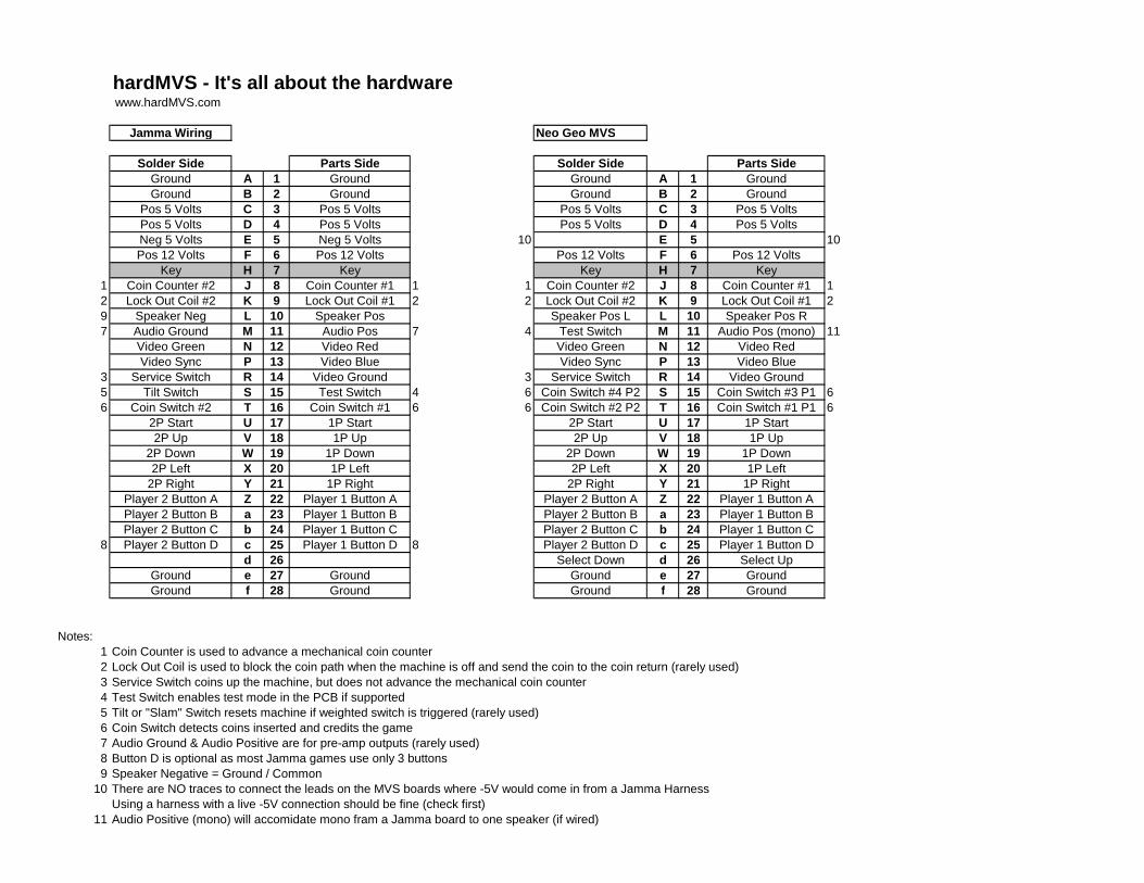
hardMVS - It's all about the hardware www.hardMVS.com
Jamma Wiring Neo Geo MVS
Solder Side Parts Side Solder Side Parts SideGround A 1 Ground Ground A 1 GroundGround B 2 Ground Ground B 2 Ground
Pos 5 Volts C 3 Pos 5 Volts Pos 5 Volts C 3 Pos 5 VoltsPos 5 Volts D 4 Pos 5 Volts Pos 5 Volts D 4 Pos 5 VoltsNeg 5 Volts E 5 Neg 5 Volts 10 E 5 10Pos 12 Volts F 6 Pos 12 Volts Pos 12 Volts F 6 Pos 12 Volts
Key H 7 Key Key H 7 Key1 Coin Counter #2 J 8 Coin Counter #1 1 1 Coin Counter #2 J 8 Coin Counter #1 12 Lock Out Coil #2 K 9 Lock Out Coil #1 2 2 Lock Out Coil #2 K 9 Lock Out Coil #1 29 Speaker Neg L 10 Speaker Pos Speaker Pos L L 10 Speaker Pos R7 Audio Ground M 11 Audio Pos 7 4 Test Switch M 11 Audio Pos (mono) 11
Video Green N 12 Video Red Video Green N 12 Video RedVideo Sync P 13 Video Blue Video Sync P 13 Video Blue
3 Service Switch R 14 Video Ground 3 Service Switch R 14 Video Ground5 Tilt Switch S 15 Test Switch 4 6 Coin Switch #4 P2 S 15 Coin Switch #3 P1 66 Coin Switch #2 T 16 Coin Switch #1 6 6 Coin Switch #2 P2 T 16 Coin Switch #1 P1 6
2P Start U 17 1P Start 2P Start U 17 1P Start2P Up V 18 1P Up 2P Up V 18 1P Up
2P Down W 19 1P Down 2P Down W 19 1P Down2P Left X 20 1P Left 2P Left X 20 1P Left
2P Right Y 21 1P Right 2P Right Y 21 1P RightPlayer 2 Button A Z 22 Player 1 Button A Player 2 Button A Z 22 Player 1 Button APlayer 2 Button B a 23 Player 1 Button B Player 2 Button B a 23 Player 1 Button BPlayer 2 Button C b 24 Player 1 Button C Player 2 Button C b 24 Player 1 Button C
8 Player 2 Button D c 25 Player 1 Button D 8 Player 2 Button D c 25 Player 1 Button Dd 26 Select Down d 26 Select Up
Ground e 27 Ground Ground e 27 GroundGround f 28 Ground Ground f 28 Ground
Notes:1 Coin Counter is used to advance a mechanical coin counter2 Lock Out Coil is used to block the coin path when the machine is off and send the coin to the coin return (rarely used)3 Service Switch coins up the machine, but does not advance the mechanical coin counter4 Test Switch enables test mode in the PCB if supported5 Tilt or "Slam" Switch resets machine if weighted switch is triggered (rarely used)6 Coin Switch detects coins inserted and credits the game7 Audio Ground & Audio Positive are for pre-amp outputs (rarely used)8 Button D is optional as most Jamma games use only 3 buttons9 Speaker Negative = Ground / Common
10 There are NO traces to connect the leads on the MVS boards where -5V would come in from a Jamma HarnessUsing a harness with a live -5V connection should be fine (check first)
11 Audio Positive (mono) will accomidate mono fram a Jamma board to one speaker (if wired)
![3M 4-Wall, Tripolarized Header.050 ± .002 [1. 27].100 ± .002 [2.54].045 - .060 [1.14] - [1.52].025 - .035 [0.64] - [0.89] *Solder Thief Solder Pads required only on Solder side of](https://img.dokumen.tips/doc/110x75/5fe03dc705d5a574ed2b86e9/3m-4-wall-tripolarized-header-050-002-1-27100-002-254045-060.jpg)