Embed Size (px)
Citation preview

Hitachi Ultrastar 15K300 SCSI Hard Disk Drive Specification
Hard Disk Drive Specification
Ultrastar 15K3003.5 inch SCSI Hard Disk Drive
Models: HUS153030VL3800HUS153014VL3800HUS153073VL3800
Version 1.0 09 April 2007
Warning: Printed copies of this document are considered current only on the date of print. Replacement and disposal of down-level versions is the responsibility of the document holder.

HItachi Ultrastar 15K300 SCSI Hard Disk Drive Specification

Hitachi Ultrastar 15K300 SCSI Hard Disk Drive Specification
Hard Disk Drive Specification
Ultrastar 15K3003.5 inch SCSI Hard Disk Drive
Models: HUS153030VL3800HUS153014VL3800HUS153073VL3800
Version 1.0 09 April 2007
Warning: Printed copies of this document are considered current only on the date of print. Replacement and disposal of down-level versions is the responsibility of the document holder.

Hitachi Ultrastar 15K300 SCSI Hard Disk Drive Specification
1st Edition (Rev. 1.0) (09 April 2007)
The following paragraph does not apply to the United Kingdom or any country where such provisions are inconsistent with local law: HITACHI GLOBAL STORAGE TECHNOLOGIES PROVIDES THIS PUBLICATION "AS IS" WITHOUT WARRANTY OF ANY KIND, EITHER EXPRESS OR IMPLIED, INCLUDING, BUT NOT LIMITED TO, THE IMPLIED WARRANTIES OF MERCHANTABILITY OR FITNESS FOR A PARTICULAR PURPOSE. Some states do not allow disclaimer or express or implied warranties in certain transactions, therefore, this statement may not apply to you.This publication could include technical inaccuracies or typographical errors. Changes are periodically made to the informa-tion herein; these changes will be incorporated in new editions of the publication. Hitachi may make improvements or changes in any products or programs described in this publication at any time.
It is possible that this publication may contain reference to, or information about, Hitachi products (machines and programs), programming, or services that are not announced in your country. Such references or information must not be construed to mean that Hitachi intends to announce such Hitachi products, programming, or services in your country.
Technical information about this product is available by contacting your local Hitachi Global Storage Technologies represen-tative or on the Internet at http://www.hitachigst.com
Hitachi Global Storage Technologies may have patents or pending patent applications covering subject matter in this docu-ment. The furnishing of this document does not give you any license to these patents.
©Copyright Hitachi Globlal Storage Technologies
Note to U.S. Government Users —Documentation related to restricted rights —Use, duplication or disclosure is subject to restrictions set forth in GSA ADP Schedule Contract with Hitachi Global Storage Technologies.
Hitachi Ultrastar 15K300 SCSI Hard Disk Drive Specification
Table of Contents1.0 General............................................................................................................................1
1.1 Introduction................................................................................................................11.2 Glossary .....................................................................................................................11.3 Caution.......................................................................................................................1
2.0 Outline of the drive ........................................................................................................33.0 Fixed-disk Subsystem Description ...............................................................................5
3.1 Control Electronics ....................................................................................................53.2 Head Disk Assembly .................................................................................................53.3 Actuator .....................................................................................................................5
4.0 Drive characteristics ......................................................................................................74.1 Formatted capacity.....................................................................................................74.2 Data sheet...................................................................................................................74.3 Inquiry information....................................................................................................8
4.3.1 Product ID.........................................................................................................84.3.2 Worldwide ID - Block assignment ...................................................................8
4.4 Cylinder allocation.....................................................................................................94.5 Performance characteristics .......................................................................................9
4.5.1 Mechanical positioning.....................................................................................104.5.2 Drive ready time ...............................................................................................124.5.3 Spindle stop time ..............................................................................................124.5.4 Data transfer speed............................................................................................124.5.5 Buffering operation (read ahead/write cache)...................................................13
5.0 Data Integrity .................................................................................................................155.1 Equipment Status .......................................................................................................155.2 Error Recovery Procedure..........................................................................................15
6.0 Physical format ..............................................................................................................176.1 Shipped format (Plist) ................................................................................................176.2 Reassigned format (Glist) ..........................................................................................17
7.0 Electrical interface .........................................................................................................197.1 SCA connector ...........................................................................................................19
7.1.1 SCSI signal connector (80-pin SCA-2 model) .................................................207.2 SCSI cable..................................................................................................................217.3 SCSI bus terminator...................................................................................................217.4 Hot plug/unplug .........................................................................................................217.5 SCSI bus electrical characteristics .............................................................................217.6 Option jumper block ..................................................................................................227.7 Jumper signal Description on 80 pin Jumper Block ..................................................23
7.7.1 Disable Auto Spin (position 1-2) ......................................................................237.7.2 Auto Spin Delay and Delay Spin 12 / 6 (position 3-4 and position 5-6) ..........237.7.3 Force Single Ended Mode (position 7-8)..........................................................237.7.4 Reserved (position 9-10)...................................................................................237.7.5 LED Driver Out (position 11-12) .....................................................................24

HItachi Ultrastar 15K300 SCSI Hard Disk Drive Specification
8.0 Environment...................................................................................................................258.1 Temperature and humidity.........................................................................................258.2 Storage requirements .................................................................................................26
8.2.1 Packaging..........................................................................................................268.2.2 Storage time ......................................................................................................26
8.3 Corrosion test .............................................................................................................268.4 Cooling requirements.................................................................................................27
9.0 DC power requirements ................................................................................................299.1 Power supply current, average, and peak...................................................................309.2 Ripple voltage ............................................................................................................329.3 Power consumption efficiency index.........................................................................32
10.0 Reliability......................................................................................................................3310.1 Start/stop cycles .......................................................................................................3310.2 Data reliability .........................................................................................................3310.3 Seek errors ...............................................................................................................3310.4 Failure prediction (PFA/S.M.A.R.T) .......................................................................3310.5 Preventive maintenance ...........................................................................................3310.6 Temperature warning ...............................................................................................33
11.0 Mechanical specifications............................................................................................3511.1 Outline .....................................................................................................................3511.2 Mechanical dimensions............................................................................................3511.3 Interface connector - 80 pin .....................................................................................3711.4 Mounting positions and tappings .............................................................................3811.5 Drive mounting ........................................................................................................4011.6 Heads unload and actuator lock ...............................................................................40
12.0 Vibration and shock.....................................................................................................4112.1 Operating vibration ..................................................................................................41
12.1.1 Random vibration ...........................................................................................4112.1.2 Swept sine vibration.......................................................................................41
12.2 Non-operating vibration...........................................................................................4112.2.1 Random vibration ...........................................................................................4112.2.2 Swept sine vibration........................................................................................41
12.3 Operating shock .......................................................................................................4112.4 Non-operating shock...............................................................................................42
12.4.1 Half sinewave shock pulse..............................................................................4212.4.2 Rotational shock ............................................................................................42
13.0 Acoustics .......................................................................................................................4313.1 Sound power levels ..................................................................................................43
14.0 Identification ................................................................................................................4514.1 Labels.......................................................................................................................45
15.0 Electromagnetic Compatibility...................................................................................4715.1 Class B Regulatory Notices .....................................................................................47
16.0 Standards ......................................................................................................................4916.1 UL and CSA standard conformity ...........................................................................4916.2 European standards compliance...............................................................................4916.3 German safety mark.................................................................................................49

Hitachi Ultrastar 15K300 SCSI Hard Disk Drive Specification
16.4 Flammability ............................................................................................................4916.5 Corporate Standards Compliance ............................................................................49
17.0 SCSI Command Set .....................................................................................................5117.1 SCSI Control Byte ...................................................................................................5317.2 Abbreviations...........................................................................................................5317.3 Byte ordering conventions .......................................................................................5317.4 FORMAT UNIT (04)...............................................................................................54
17.4.1 Parameter List Header ....................................................................................5617.4.2 Defect Descriptor ............................................................................................57
17.5 INQUIRY (12) .........................................................................................................6117.5.1 Inquiry Data ....................................................................................................62
17.6 LOG SELECT (4C) .................................................................................................7217.7 LOG SENSE (4D) ...................................................................................................75
17.7.1 Log Page parameters.......................................................................................7617.7.2 Log Sense Page 0 ............................................................................................7717.7.3 Log Sense Page 2 ............................................................................................7817.7.4 Log Sense Page 3 ............................................................................................8017.7.5 Log Sense Page 5 ............................................................................................8217.7.6 Log Sense Page 6 ............................................................................................8417.7.7 Log Sense Page D ...........................................................................................8517.7.8 Log Sense Page E ...........................................................................................8617.7.9 Log Sense Page F............................................................................................8717.7.10 Log Sense Page 10........................................................................................8817.7.11 Log Sense Page 15........................................................................................9117.7.12 Log Sense Page 2F........................................................................................9417.7.13 Log Sense Page 30........................................................................................9517.7.14 Log Sense Page 37........................................................................................98
17.8 MODE SELECT (15) ..............................................................................................10017.9 MODE SELECT (55) ..............................................................................................10117.10 MODE SENSE (1A) ..............................................................................................102
17.10.1 Mode Parameter List.....................................................................................10317.10.2 Mode Page 00 (Vendor Unique Parameters) ................................................10717.10.3 Mode Page 01 (Read/Write Error Recovery Parameters).............................11017.10.4 Mode Page 02 (Disconnect/Reconnect Parameters) .....................................11517.10.5 Mode Page 03 (Format Device Parameters) .................................................11717.10.6 Mode Page 04 (Rigid Disk Drive Geometry Parameters) ............................11917.10.7 Mode Page 07 (Verify Error Recovery Parameters).....................................12017.10.8 Mode Page 08 (Caching Parameters)............................................................12117.10.9 Mode Page 0A (Control Mode Page Parameters).........................................12317.10.10 Control Extension Subpage ........................................................................12417.10.11 Mode Page 0C (Notch Parameters) ............................................................12517.10.12 Mode page 19 (Port Control Parameters) ...................................................12717.10.13 Mode Page 1A (Power Control) .................................................................13317.10.14 Mode Page 1C (Informational Exceptions Control) ...................................134
17.11 MODE SENSE (5A) ..............................................................................................13717.12 PERSISTENT RESERVE IN (5E) ........................................................................139

HItachi Ultrastar 15K300 SCSI Hard Disk Drive Specification
17.12.1 Service Action...............................................................................................13917.12.2 Parameter data for Read Keys ......................................................................14017.12.3 Parameter Data for Read Reservations .........................................................141
17.13 PERSISTENT RESERVE OUT (5F) ....................................................................14217.13.1 Service Action...............................................................................................14317.13.2 Type ..............................................................................................................14317.13.3 Parameter list ................................................................................................14417.13.4 Summary.......................................................................................................145
17.14 PRE-FETCH (34) ..................................................................................................14717.15 READ (6) - (08) .....................................................................................................14817.16 READ (10) - (28) ...................................................................................................14917.17 READ (12) - (A8) ..................................................................................................15117.18 READ (16) - (88) ...................................................................................................15217.19 READ BUFFER (3C) ............................................................................................153
17.19.1 Combined Header And Data (Mode 00000b)...............................................15417.19.2 Read Data (Mode 00010b)............................................................................15417.19.3 Descriptor (Mode 00011b)............................................................................15517.19.4 Read Data from Echo Buffer (Mode 01010b) ..............................................15617.19.5 Echo Buffer Descriptor (Mode 01011b) .......................................................15617.19.6 Enable Expander Communications Protocol and Echo Buffer (Mode 11010b)156
17.20 READ CAPACITY (10) - (25) ..............................................................................15717.21 READ CAPACITY (16) (9E/10)...........................................................................159
17.21.1 Returned Data Format...................................................................................15917.22 READ DEFECT DATA (37).................................................................................160
17.22.1 Defect List Header ........................................................................................16217.22.2 Defect List Descriptor...................................................................................16217.22.3 Bytes from Index Format (100b) ..................................................................16317.22.4 Physical Sector Format (101b) .....................................................................163
17.23 READ DEFECT DATA (B7) ................................................................................16417.23.1 Defect List Header ........................................................................................16417.23.2 Defect List Descriptor...................................................................................16517.23.3 Bytes from Index Format (100b) ..................................................................16517.23.4 Physical Sector Format (101b) .....................................................................165
17.24 READ LONG (3E) ................................................................................................16617.25 REASSIGN BLOCKS (07) ...................................................................................16717.26 RECEIVE DIAGNOSTICS RESULTS (1C) ........................................................169
17.26.1 Receive Diagnostic Results Page 0...............................................................16917.26.2 Receive Diagnostic Results Page 40.............................................................170
17.27 RELEASE (17) ......................................................................................................17217.28 RELEASE (57) ......................................................................................................17317.29 REPORT DEVICE IDENTIFIER (A3/05)............................................................17417.30 REPORT LUNS (A0) ............................................................................................17617.31 REPORT SUPPORTED OPERATION CODES (A3/0C) ....................................177
17.31.1 All_commands parameter data format..........................................................17817.31.2 One_command parameter data format..........................................................179
17.32 REPORT SUPPORTED TASK MANAGEMENT FUNCTIONS (A3/0D) .........180

Hitachi Ultrastar 15K300 SCSI Hard Disk Drive Specification
17.33 REQUEST SENSE (03).........................................................................................18217.34 RESERVE (16) ......................................................................................................18317.35 RESERVE (56) ......................................................................................................18417.36 REZERO UNIT (01)..............................................................................................18517.37 SEEK (6) - (0B) .....................................................................................................18617.38 SEEK (10) - (2B) ...................................................................................................18617.39 SEND DIAGNOSTIC (1D) ...................................................................................187
17.39.1 Send Diagnostic Page 0 ................................................................................18917.39.2 Send Diagnostic Page 40 ..............................................................................189
17.40 SET DEVICE IDENTIFIER (A4/06) ....................................................................19117.41 START STOP UNIT (1B) .....................................................................................19217.42 SYNCHRONIZE CACHE (10) - (35) ...................................................................19317.43 SYNCHRONIZE CACHE (16) - (91) ...................................................................19417.44 TEST UNIT READY (00) .....................................................................................19517.45 VERIFY (2F) .........................................................................................................19617.46 VERIFY (12) - (AF) ..............................................................................................19917.47 VERIFY (16) - (8F) ...............................................................................................20017.48 WRITE (6) - (0A) ..................................................................................................20117.49 WRITE (10) - (2A) ................................................................................................20217.50 WRITE (12) - (AA) ...............................................................................................20517.51 WRITE (16) - (8A) ................................................................................................20617.52 WRITE AND VERIFY (10) - (2E)........................................................................20717.53 WRITE AND VERIFY (12) - (AE).......................................................................20817.54 WRITE AND VERIFY (16) - (8E)........................................................................20917.55 WRITE BUFFER (3B) ..........................................................................................210
17.55.1 Combined Header And Data (Mode 00000b)...............................................21017.55.2 Write Data (Mode 00010b)...........................................................................21117.55.3 Download Microcode (Mode 00100b) .........................................................21217.55.4 Download Microcode and Save (Mode 00101b) -Single Binary File ..........21217.55.5 Download Microcode and Save (Mode 00111b) - Multiple Binary Files ....21217.55.6 Write Data to Echo Buffer (Mode 01010b) ..................................................21317.55.7 Enable Expander Communications Protocol (Mode 11010b) ......................213
17.56 WRITE LONG (3F)...............................................................................................21417.57 WRITE SAME (41) ...............................................................................................21517.58 WRITE SAME (16) - (93) .....................................................................................216
18.0 SCSI Status Byte ..........................................................................................................21719.0 SCSI message system ...................................................................................................219
19.1 Supported messages .................................................................................................22019.1.1 Task Complete (00) ........................................................................................22019.1.2 Synchronous Data Transfer Request (01, 03, 01h) .........................................22119.1.3 Wide Data Transfer Request (01, 02, 03h) .....................................................22519.1.4 Parallel Protocol Request (01, 06, 04h) ..........................................................22719.1.5 Save Data Pointer (02) ....................................................................................22919.1.6 Restore Pointers (03) ......................................................................................22919.1.7 Disconnect (04)...............................................................................................23019.1.8 Initiator Detected Error (05) ...........................................................................230

HItachi Ultrastar 15K300 SCSI Hard Disk Drive Specification
19.1.9 Abort Task Set (06).........................................................................................23019.1.10 Message Reject (07)......................................................................................23019.1.11 No Operation (08) .........................................................................................23019.1.12 Message Parity Error (09).............................................................................23119.1.13 Linked Task Complete (0A) .........................................................................23119.1.14 Linked Task Complete With Flag (0B) ........................................................23119.1.15 Target Reset (0C)..........................................................................................23119.1.16 Abort Task (0D)............................................................................................23119.1.17 Clear Task Set (0E).......................................................................................23119.1.18 Logical Unit Reset (17).................................................................................23119.1.19 Queue Tag messages (20H, 21H, 22H) ........................................................23219.1.20 Ignore Wide Residue ....................................................................................23219.1.21 Identify (80 - FF) ..........................................................................................233
19.2 Supported message functions...................................................................................23419.3 Attention condition ..................................................................................................235
20.0 Additional information................................................................................................23720.1 SCSI Protocol ..........................................................................................................237
20.1.1 Priority of SCSI Status Byte Reporting ..........................................................23720.1.2 Invalid LUN in Identify Message ...................................................................23720.1.3 Incorrect Initiator Connection.........................................................................23820.1.4 Command Processing During Execution of Active I/O Process ....................23820.1.5 Unit Attention Condition ................................................................................24020.1.6 Command processing during startup and format operations ..........................24120.1.7 Internal Error Condition..................................................................................24120.1.8 Deferred Error Condition................................................................................24120.1.9 Degraded Mode...............................................................................................24220.1.10 Command Processing while Reserved..........................................................249
20.2 Priority Commands ..................................................................................................24920.3 Command Queuing ..................................................................................................250
20.3.1 Queue Depth ...................................................................................................25020.3.2 Tagged Queuing..............................................................................................25020.3.3 Untagged Queuing ..........................................................................................25020.3.4 Command Queuing Rule ................................................................................25020.3.5 Queue Full Status............................................................................................25020.3.6 Device Behavior on Command Queuing ........................................................250
20.4 Command Reordering..............................................................................................25120.5 Concurrent I/O Process ............................................................................................25120.6 Write Cache .............................................................................................................25120.7 Automatic Rewrite/Reallocate .................................................................................25120.8 Segmented Caching .................................................................................................254
20.8.1 Overview.........................................................................................................25420.8.2 Read Ahead.....................................................................................................254
20.9 Multiple Initiator Systems .......................................................................................25420.9.1 Sense Data.......................................................................................................25420.9.2 Mode Pages.....................................................................................................254
20.10 Reselection Time-out .............................................................................................254

Hitachi Ultrastar 15K300 SCSI Hard Disk Drive Specification
20.11 Single Initiator Selection .......................................................................................25420.12 Non-arbitrating systems .........................................................................................25420.13 Selection without ATN ..........................................................................................25520.14 Multiple Initiator Environment ..............................................................................255
20.14.1 Initiator Sense Data.......................................................................................25520.14.2 Initiator Mode Select/Mode Sense Parameters .............................................25520.14.3 Initiator Data Transfer Mode Parameter .......................................................255
20.15 Contingent Allegiance Condition ..........................................................................25520.16 Reset.......................................................................................................................255
20.16.1 Reset Sources ................................................................................................25620.16.2 Reset Actions ................................................................................................256
20.17 Diagnostics.............................................................................................................25620.17.1 Power on Diagnostics ...................................................................................25620.17.2 Self-test via SEND DIAGNOSTIC Command.............................................257
20.18 Idle Time Function.................................................................................................26020.19 Command Time out Limits ...................................................................................260
20.19.1 Reassignment Time.......................................................................................26020.19.2 Format Time .................................................................................................26020.19.3 Start/Stop Unit Time.....................................................................................26020.19.4 Medium Access Command Time .................................................................26120.19.5 Time-out Limits for Other Commands .........................................................261
20.20 Recommended Initiator ERP .................................................................................26220.20.1 Drive Service Strategy ..................................................................................26220.20.2 Recommendations for System Error Log .....................................................26320.20.3 Data Recovery Procedure .............................................................................26320.20.4 Nondata Error Recovery Procedure ..............................................................265
21.0 SCSI Sense Data...........................................................................................................27121.1 SCSI Sense Data Format..........................................................................................27121.2 Sense Data Description ............................................................................................272
21.2.1 Valid (Bit 7 of byte 0).....................................................................................27221.2.2 Error Code (Bit 6 - 0 of byte 0) ......................................................................27221.2.3 ILI: Incorrect Length Indicator (Bit 5 of byte 2) ............................................27221.2.4 Sense Key (Bit 3 - 0 of byte 2) .......................................................................27321.2.5 Information Bytes (Byte 3 through 6).............................................................27421.2.6 Additional Sense Length (Byte 7) ..................................................................27421.2.7 Command Specific Information (Byte 8 through 11) .....................................27421.2.8 Additional Sense Code/Qualifier (Byte 12 and 13) ........................................27521.2.9 RU: Field Replaceable Unit (Byte 14)............................................................29321.2.10 Sense Key Specific (Byte 15 through 17).....................................................29321.2.11 Reserved (Byte 18 through 19) .....................................................................29521.2.12 Vendor unique error information (Byte 20 through 23) ...............................29521.2.13 Physical Error Record (Byte 24 thru 29) ......................................................29521.2.14 Reserved (Byte 30 through 31) .....................................................................295
22.0 Appendix. UEC list .....................................................................................................297

HItachi Ultrastar 15K300 SCSI Hard Disk Drive Specification

Hitachi Ultrastar 15K300 SCSI Hard Disk Drive Specification
List of TablesTable 1.Product ID table ............................................................................................1Table 2.Formatted capacity........................................................................................7Table 3.Data sheet......................................................................................................7Table 4.Product ID in Inquiry Command ..................................................................8Table 5.Block assignment of worldwide ID in INQUIRY Command ......................8Table 6.Cylinder allocation........................................................................................9Table 7.Mechanical positioning performance ...........................................................10Table 8.Full stroke seek time .....................................................................................11Table 9.Latency time .................................................................................................11Table 10.Drive ready time .........................................................................................12Table 11.Spindle stop time ........................................................................................12Table 12.Data transfer speed (sector size 512 Byte case)..........................................12Table 13.Table of signals (80-pin).............................................................................20Table 14.Auto start delay & delay start 6/12 drive behavior.....................................23Table 15.Operating and non-operating conditions ....................................................25Table 16.Maximum allowable surface temperatures .................................................27Table 17.Input voltage ...............................................................................................29Table 18.Power supply generated ripple at drive power connector...........................32Table 19.Power consumption efficiency index..........................................................32Table 20.Physical dimensions....................................................................................35Table 21.Interface connector - 80 pin ........................................................................37Table 22.A-weighted sound power levels..................................................................43Table 23.SCSI Commands Supported .......................................................................51Table 24.SCSI Control Byte ......................................................................................53Table 25.FORMAT UNIT (04) .................................................................................54Table 26.Format of the Parameter List Header..........................................................56Table 27. Initialization Pattern Descriptor:................................................................57Table 28.Defect Descriptor - Block Format (for n + 1 defects) ................................58Table 29.Defect Descriptor - Bytes From Index Format (for n = 1 defects) .............59Table 30.Defect Descriptor - Physical Sector Format (for n + 1 defects) .................60Table 31.INQUIRY (12)............................................................................................61Table 32.Page Code descriptions...............................................................................61Table 33.Inquiry Data- EVPD = 0 .............................................................................62Table 34.Inquiry Data - EVPD = 1 (Page Code = 00h).............................................64Table 35.Inquiry Data - EVPD = 1 (Page Code = 03h).............................................65Table 36.Inquiry Data - EVPD = 1 (Page Code = 80h).............................................67Table 37.Inquiry Data - EVPD = 1 (Page Code = 83h).............................................68Table 38.Inquiry Data - EVPD = 1 (Page Code = D1h) ............................................70Table 39.Inquiry Data - EVPD = 1 (Page Code = D2h) ............................................71Table 40.Log Select (4C)...........................................................................................72Table 41.Log Sense (4D) ...........................................................................................75Table 42.Log Sense Page 0........................................................................................77Table 43.Log Sense Page 2 (part 1 of 2)....................................................................78Table 44.Log Sense Page 2 (part 2 of 2)....................................................................78
HItachi Ultrastar 15K300 SCSI Hard Disk Drive Specification
Table 45.Log Sense Page 3 (part 1 of 2)....................................................................80Table 46.Log Sense Page 3 (part 2 of 2)....................................................................80Table 47.Log Sense Page 5 (part 1 of 2)....................................................................82Table 48.Log Sense Page 5 (part 2 of 2)....................................................................83Table 49.Log Sense Page 6........................................................................................84Table 50.Log Sense Page D.......................................................................................85Table 51.Log Sense Page E .......................................................................................86Table 52.Log Sense Page F........................................................................................87Table 53.Log Sense Page F, Application Client Log ................................................87Table 54.Log Sense Page 10......................................................................................88Table 55.Log Sense Page 10, self-test results............................................................88Table 56.Log Sense Page 10, self-test results............................................................89Table 57.Log Sense Page 10, Extended Segment Number........................................90Table 58.Log Sense Page 15......................................................................................91Table 59. Log Sense Page 2F.....................................................................................94Table 60.Log Sense Page 30......................................................................................95Table 61.Log Sense Page 37......................................................................................98Table 62.Mode Select (15).........................................................................................100Table 63.Mode Select (55).........................................................................................101Table 64.Mode Sense (1A) ........................................................................................102Table 65.Page Code Usage ........................................................................................103Table 66.Mode parameter header (6).........................................................................103Table 67.Mode parameter header (10).......................................................................104Table 68.Mode Parameter Block Descriptor .............................................................105Table 69.Mode Parameter Page Format ....................................................................106Table 70.Mode Parameter Page Format ....................................................................106Table 71.Vendor Unique Parameters - Page00..........................................................107Table 72.Mode Page 01 (Vendor Unique Parameters) ..............................................110Table 73.Mode Page 02 (Disconnect/Reconnect Parameters)...................................115Table 74.Mode Page 03 (Format Device Parameters) ...............................................117Table 75.Mode Page 04 (Rigid Disk Drive Geometry Parameters) ..........................119Table 76.Mode Page 07 (Verify Error Recovery Parameters)...................................120Table 77.Page 08 (Caching Parameters)....................................................................121Table 78.Page 0A (Control Mode Page Parameters) .................................................123Table 79.Control Extension Subpage ........................................................................124Table 80.Page 0C (Notch Parameters).......................................................................125Table 81.Short (Port Control Parameters) Short Format ..........................................127Table 82.Page 19 (Port Control Parameters) Long Format .......................................128Table 83.Margin Control Subpage.............................................................................129Table 84.Saved Training Configuration Subpage......................................................130Table 85.Negotiated Settings Subpage ......................................................................131Table 86.Report Transfer Capabilities Subpage ........................................................132Table 87.Page 1A (Power Control)............................................................................133Table 88.Page 1C (Informational Exceptions Control) .............................................134Table 89.Background Control (Subpage 01h) ...........................................................136Table 90.Mode Sense (5A) ........................................................................................137

Hitachi Ultrastar 15K300 SCSI Hard Disk Drive Specification
Table 91.Persistent Reserve In (5E) ..........................................................................139Table 92.PERSISTENT RESERVE IN, Service Action Codes ................................139Table 93.PERSISTENT RESERVE IN, parameter data for Read Keys ...................140Table 94.PERSISTENT RESERVE IN, parameter data for Read Reservations.......141Table 95.PERSISTENT RESERVE IN, Read Reservation Descriptor.....................141Table 96.PERSISTENT RESERVE OUT (5F) .........................................................142Table 97.PERSISTENT RESERVE OUT, Service Action Code..............................143Table 98.PERSISTENT RESERVE OUT, Type Code .............................................143Table 99.Parameter List .............................................................................................144Table 100.PERSISTENT RESERVE OUT, Service Action, Parameters .................145Table 101.APTPL and information held by a drive...................................................146Table 102.PRE-FETCH (34) .....................................................................................147Table 103.READ (6) - (08)........................................................................................148Table 104.READ (10) - (28) .....................................................................................149Table 105.Read (12) - (A8)........................................................................................151Table 106.READ (16) - (88)......................................................................................152Table 107.READ BUFFER (3C) ...............................................................................153Table 108.Read Buffer Header ..................................................................................154Table 109.Read Buffer Description ...........................................................................155Table 110.Echo Buffer Descriptor.............................................................................156Table 111.READ CAPACITY (10) - (25).................................................................157Table 112.Format of READ CAPACITY command reply........................................158Table 113.Read Capcity (16) (9E/10)........................................................................159Table 114.Returned Data Format...............................................................................159Table 115.READ DEFECT DATA (37)....................................................................160Table 116.Defect List Format ....................................................................................161Table 117.Defect List Header ....................................................................................162Table 118.Defect List Descriptor...............................................................................162Table 119.Defect Descriptors of Bytes from Index Format ......................................163Table 120.Defect Descriptors of Physical Sector Format..........................................163Table 121.READ DEFECT DATA (B7) ...................................................................164Table 122.Defect List Header ....................................................................................164Table 123.Defect List Descriptor...............................................................................165Table 124.Defect Descriptors of Bytes from Index Format ......................................165Table 125.Defect Descriptors of Physical Sector Format..........................................165Table 126.READ LONG (3E) ...................................................................................166Table 127.REASSIGN BLOCKS (07) ......................................................................167Table 128.Format of Reassign Blocks data ...............................................................168Table 129.RECEIVE DIAGNOSTIC RESULTS (1C) .............................................169Table 130.Receive Diagnostic Results page 0...........................................................169Table 131.Receive Diagnostic Results Page 40.........................................................170Table 132.Translated address ....................................................................................171Table 133.RELEASE (17) .........................................................................................172Table 134.RELEASE (57) .........................................................................................173Table 135.REPORT DEVICE IDENTIFIER (A3/05)...............................................174Table 136.Report Device Identifier parameter list ....................................................175

HItachi Ultrastar 15K300 SCSI Hard Disk Drive Specification
Table 137.REPORT LUNS (A0) ...............................................................................176Table 138.LUN Reporting parameter list format.......................................................176Table 139.Report Supported Tasks Management Functions (A3/0D) ......................180Table 140.REQUEST SENSE (03) ...........................................................................182Table 141.RESERVE (16) .........................................................................................183Table 142.RESERVE (56) .........................................................................................184Table 143.REZERO UNIT (01).................................................................................185Table 144.SEEK (6) - (0B) ........................................................................................186Table 145.SEEK (10) - (2B) ......................................................................................186Table 146.SEND DIAGNOSTIC (1D) ......................................................................187Table 147.SEND DIAGNOSTIC Function Code (1D) .............................................188Table 148.Diagnostic Page 0 .....................................................................................189Table 149.Diagnostic Page 40 ...................................................................................189Table 150.Address to translate...................................................................................190Table 151.SET DEVICE IDENTIFIER (A4/06) .......................................................191Table 152.SET DEVICE IDENTIFIER, Parameter List ...........................................191Table 153.START STOP UNIT (1B) ........................................................................192Table 154.SYNCHRONIZE CACHE (35) ................................................................193Table 155.Synchronize Cache (16) - (91)..................................................................194Table 156.TEST UNIT READY (00)........................................................................195Table 157.VERIFY (2F) ............................................................................................196Table 158.Verify (12) - (AF) .....................................................................................199Table 159.Verify (16) - (8F) ......................................................................................200Table 160.WRITE (6) - (0A) .....................................................................................201Table 161.WRITE (10) - (2A) ...................................................................................202Table 162.Write (12) - (AA)......................................................................................205Table 163.Write (16) - (8A).......................................................................................206Table 164.WRITE AND VERIFY (10) - (2E) ..........................................................207Table 165.Write andVerify (12) - (AE) .....................................................................208Table 166.Write and Verify (16) - (8E) .....................................................................209Table 167.WRITE BUFFER (3B) .............................................................................210Table 168.Write Buffer Header .................................................................................211Table 169.WRITE LONG (3F)..................................................................................214Table 170.WRITE SAME (41) ..................................................................................215Table 171.Write Same (16) - (93)..............................................................................216Table 172.SCSI Status Byte. Format of the SCSI STATUS byte. ...........................217Table 173.Synchronous Data Transfer Request. .......................................................221Table 174.Initiator Request/Target Response (LVD mode) ......................................222Table 175.Initiator Request/Target Response (SE mode) .........................................223Table 176.Target response to Initiator's transfer period (LVD mode) ......................224Table 177.Target response to Initiator's transfer period (SE mode) ..........................225Table 178.Wide Data Transfer Request.....................................................................226Table 179.Initiator request/Target response ..............................................................226Table 180.Target request to Initiator .........................................................................227Table 181.Parallel Protocol Request..........................................................................227Table 182.Initiator Request/Target Response (DT_REQ = 1, IU_REQ = 1) ............228

Hitachi Ultrastar 15K300 SCSI Hard Disk Drive Specification
Table 183.Initiator Request/Target Response (DT_REQ = 1, IU_REQ = 0) ............228Table 184.Initiator Request/Target Response (DT_REQ = 0, IU_REQ = 0) ............228Table 185.Bit position table for Byte 7 of Parallel Protocol Request........................229Table 186.Queue Tag messages.................................................................................232Table 187.Ignore Wide Residue message format ......................................................232Table 188.Spindle Motor Degraded Mode - Disable Auto Start ...............................242Table 189.Spindle Motor Degraded Mode - Auto Start Delay/Spinning Up ............244Table 190.Spindle Motor Degraded Mode - Spindle Start Failure............................245Table 191.Spindle Motor Degraded Mode - Spindle Stopped by Unit Stop Command246Table 192.Self Configuration Failure Degraded Mode ............................................247Table 193.Format Command Failure Degraded Mode ..............................................248Table 194.Sense data combinations with auto/recommend rewrite/reallocate..........253Table 195.Short and Extended Self-Test Description ...............................................258Table 196.Recommend Reassign Errors....................................................................264Table 197.Log Only Errors ........................................................................................264Table 198.Format of Sense Data................................................................................271Table 199.Field Pointer Bytes ...................................................................................293Table 200.Actual Retry Count ...................................................................................294Table 201.Progress Indication ...................................................................................295Table 202.Unit Error Codes list .................................................................................297

HItachi Ultrastar 15K300 SCSI Hard Disk Drive Specification

Hitachi Ultrastar 15K300 SCSI Hard Disk Drive Specification1
1.0 General
1.1 IntroductionThis document describes the specifications of the following Hitachi 3.5 inch SCSI drives.
Table 1: Product ID table
Note: The specifications in this document are subject to change without notice.
For technical and ordering information, please visit our website at http://www.hitachigst.com.
1.2 Glossary
Word Meaning
BMS Background Media Scan
Kb Kilobit = 1000 bits
Mb Megabit = 1,000,000 bits
GB Gigabyte = 1,000,000,000 bits
HDD Hard Disk Drive
MB Megabyte = 1,000,000 bytes
KB Kilobyte = 1000 bytes
PFA Predictive Failure Analysis
SAS Serial Attached SCSI
S.M.A.R.T. Self-Monitoring and Reporting Technology
LVD Low Voltage Differential SCSI
FC-AL Fibre Channel - Arbitrated Loop
1.3 CautionThis drive can be damaged by electrostatic discharge (ESD). Any damages incurred to the drive after its removal from the shipping package and the ESD protective bag are the responsibility of the user.
Product ID Description
HUS153030VL3800 300 GB, SCSI
HUS153014VL3800 147 GB, SCSI
HUS153073VL3800 73 GB, SCSI

Hitachi Ultrastar 15K300 SCSI Hard Disk Drive Specification
2

Hitachi Ultrastar 15K300 SCSI Hard Disk Drive Specification
3
2.0 Outline of the drive
• Storage capacities of 300 GB, 147 GB, and 73 GB• Ultra 320• Variable Sector Size (512-528 bytes/sector in multiples of 2)• Tagged Command Queuing support• Automatic read/write data transfer• 3.6 ms seek time in read operation for 300 GB• 3.4 ms seek time in read operation for 147 GB• 3.4 ms seek time in read operation for 73 GB• Adaptive read ahead algorithm• Write Cache• Back to back write• ECC on the fly• Automatic defect reallocation• Self diagnostics at power on• Closed loop actuator servo• Non head disk contact start stop• Spindle rotation of 15,000 RPM• Automatic actuator lock• PFA (SMART)• ANSI T10 Protection Information (End-to-End)

Hitachi Ultrastar 15K300 SCSI Hard Disk Drive Specification4

Hitachi Ultrastar 15K300 SCSI Hard Disk Drive Specification
5
3.0 Fixed-disk Subsystem Description
3.1 Control ElectronicsThe drive is electronically controlled by a microprocessor, logic modules, digital/analog modules and various drivers and receivers. The control electronics perform the following major functions:
• Perform self-checkout (diagnostics)
• Conduct a power-up sequence and calibrate the servo.
• Monitor various timers for head settling, servo failure, etc.
• Analyze servo signals to provide closed-loop control. These include position error signal and estimated velocity.
• Control of the voice coil motor driver to align the actuator onto a desired position
• Monitor the actuator position and determine the target track for a seek operation.
• Constantly monitor error conditions of the servo and take corresponding action if an error occurs.
• Control starting, stopping, and rotating speed of the spindle.
• Control and interpretation of all interface signals between the host controller and the drive
• Control of read/write accessing of the disk media, including defect management and error recovery
3.2 Head Disk AssemblyThe head/disk assembly (HDA) is assembled in a clean room environment and contains disks, a spindle motor, actuator assem-bly, and voice coil motor. Air is constantly circulated and filtered when the drive is operational. Venting of the HDA is accom-plished via a breather filter.
The spindle is driven directly by a brushless, sensorless DC drive motor. Dynamic braking is used to stop the spindle quickly.
3.3 ActuatorThe read/write heads are mounted in the actuator. The actuator is a swing-arm assembly driven by a voice coil motor. A closed-loop positioning servo controls the movement of the actuator. An embedded servo data pattern supplies feedback to the positioning servo to keep the read/write heads centered over the desired track.
The actuator assembly is balanced to allow vertical or horizontal mounting without adjustment.
Heads are moved out from the disks (unloaded) to protect the disk data during shipping, moving, or storage. At power down, the heads are automatically unloaded from over the disk area and the head actuator locking mechanism will secure the heads in the unload position.

Hitachi Ultrastar 15K300 SCSI Hard Disk Drive Specification
6

Hitachi Ultrastar 15K300 SCSI Hard Disk Drive Specification
7
4.0 Drive characteristics
4.1 Formatted capacityTable 2: Formatted capacity
4.2 Data sheetTable 3: Data sheet
Description HUS153030VL3800 HUS153014VL3800 HUS153073VL3800
Label capacity 300 GB 147 GB 73 GB
Number of heads 8 4 2
Number of disks 4 2 1
Total data bytes (512 bytes/sector)
300,000,739,328 147,015,821,824 73,407,900,160
Total logical data blocks
585,937,500
(22ECB25C)
287,140,277
(111D69B5h)
143,374,805
(88BB9D5h)
Buffer to/from media 864 - 1441 Mb/sec
Host to/from buffer (interface transfer rate) 320 [MB/sec]
Data buffer size 16MB
Number of buffer segments 1 - 254
Rotational speed 15,000 RPM
Recording density 824.5 [Kbpi] (Max)
Track density 137,000 [TPI] (average)
Areal density 113 [Gb/sq. in]
Data zone 20

Hitachi Ultrastar 15K300 SCSI Hard Disk Drive Specification
8
4.3 Inquiry information
4.3.1 Product IDProduct ID in section 17.5.1.1, "Inquiry Data format - CmdDt = 0, EVPD = 0, Page code = 0" on page 76. is as follows:
Table 4: Product ID in INQUIRY Command
4.3.2 Worldwide ID - Block assignmentBlock assignment of Worldwide ID is as follows:
Table 5: Block assignment of worldwide ID in INQUIRY Command
Note (1) - Additional block assignment will be issued as needed based on actual production volume
Product ID Description
HUS153030VL3800 300 GB, 80-pin
HUS153014VL3800 147 GB, 80-pin
HUS153073VL3800 73 GB, 80-pin
Manufacturing site Product Name and Associtated Models
Block assignment
Singapore
HUS153030VL3800
HUS153014VL3800
HUS153073VL3800
001h(1)

Hitachi Ultrastar 15K300 SCSI Hard Disk Drive Specification
9
4.4 Cylinder allocationTable 6: Cylinder allocation
Note: Values shown are nominal. Actual values will vary based on manufacturing optimization. Mode Page 03 (Format Device Parameters), page 117 and SectionMode Page 0C (Notch Parameters), page 125 provide methods to determine actual medium format and zone parameters for specific drives.
4.5 Performance characteristicsDrive performance is characterized by the following parameters:
•Command overhead•Mechanical head positioning
- Seek time
- Latency•Data transfer speed•Buffering operation (read ahead/write cache)
Note: All the above parameters contribute to drive performance. There are other parameters that contribute to the perfor-mance of the actual system. This specification tries to define the bare drive characteristics, not system throughput, which depends on the system and the application.
Zone Sectors/Track Cyln/zone Start Cyln End Cyln0 1080 14817 1 148181 1041 2503 14819 173212 1026 4806 17322 221273 1012 3904 22128 260324 990 5106 26033 311385 972 2303 31139 334416 918 7109 33442 405507 900 6608 40551 471588 877 3304 47159 504629 864 1501 50464 5196410 855 601 51965 5256511 810 10012 52566 6257812 765 2803 62579 6538113 756 1702 65382 6708314 742 2203 67084 6928615 720 4004 69287 7329116 702 2103 73292 7539417 675 4704 75395 8009918 648 1401 80101 8150119 630 1802 81502 83303
Cylinder Allocation ( all models)

Hitachi Ultrastar 15K300 SCSI Hard Disk Drive Specification
10
4.5.1 Mechanical positioning
4.5.1.1 Average seek time (including settling)Table 7: Mechanical positioning performance
“Typical” and “Max” are used throughout this document and are defined as follows:
Typical Average of the drive population tested at nominal environmental and voltage conditions.
Max Maximum value measured on any one drive over the full range of the environmental and voltage conditions. (See Section 8.0, “Environment” on page 25 and Section 9.0, “DC power requirements” on page 29 for ranges.)
Seek time is measured from the start of the actuator’s motion to the start of a read or write operation. Average seek time is measured as the weighted average of all possible seek combinations.
Weighted average =
Where: max = Maximum seek length n = Seek length (1 to max) Tn.in = Inward measured seek time for an n track seek Tn.out = Outward measured seek time for an n track seek
Model Command Typical (ms) Max
300 GB Read 3.6 4.7
Write 4.1 5.1
147 GB Read 3.4 4.6
Write 3.8 5.1
73 GB Read 3.4 4.6
Write 3.9 5.0
max 1 n–+ ) Tnin Tnout+(⋅( )=
n 1=
Max
∑max 1+( ) max( )⋅
------------------------------------------------------------------------------------------------

Hitachi Ultrastar 15K300 SCSI Hard Disk Drive Specification
11
4.5.1.2 Full stroke seek time
Table 8: Full stroke seek time
Full stroke seek is measured as the average of 1,000 full stroke seeks with a random head switch from both directions (inward and outward).
4.5.1.3 Average latencyTable 9: Latency time
Model Command Typical (ms) Max
300 GB Read 6.6 11.1
Write 7.1 11.5
147 GB Read 6.5 11.0
Write 6.8 11.6
73 GB Read 6.5 11.0
Write 6.9 11.4
Rotation Time for a revolution (ms) Average latency (ms)
15,000 RPM 4.0 2.0

Hitachi Ultrastar 15K300 SCSI Hard Disk Drive Specification
12
4.5.2 Drive ready timeTable 10: Drive ready time
4.5.3 Spindle stop timeTable 11: Spindle stop time
The period from power off to the complete stop of the rotating spindle is categorized as 'operating'. The Operating shock crite-ria apply during this period. Refer to section 12.3, “Operating shock” on page 54.
4.5.4 Data transfer speedTable 12: Data transfer speed (sector size 512 Byte case)
Notes:• Instantaneous disk-buffer transfer rate is derived by: (Number of sectors on a track) x 512 x (revolutions/sec)
• For this table, '1 MB / Sec' should be interpreted as 1,000,000 bytes per Second.
• The number of sectors per track will vary by zone because of the linear density recording.
• Sustained disk-buffer transfer rate is the average rate measured while transferring multiple cylinders of data. It dif-fers from the instantaneous transfer rate because of the time required to change tracks (Cylinder skew and Head skew). In addition, time is added for the occasional missed transfer.
Model Typical (sec) Maximum (sec)
300 GB Model 21.0 29.9
147 GB Model 11.5 29.9
73 GB Model 7.0 29.9
Model Typical (sec) Maximum (sec)
300 GB Model 11.0 20
147 GB Model 7.0 20
73 GB Model 4.0 20
Description
Disk-buffer transfer
Typical (MB / Sec)Zone Model Read Write
Instantaneous 0 All 138.2 138.2Measured typical values for sustained disk-buffer transfer rate
0 300 GB 123.0 120.00 147 GB 123.0 120.00 73 GB 123.0 120.0
Instantaneous 19 All 80.9 80.9Measured typical values for sustained disk-buffer transfer rate
19 300 GB 71.7 69.919 147 GB 71.7 69.919 73 GB 71.7 69.9

Hitachi Ultrastar 15K300 SCSI Hard Disk Drive Specification
13
4.5.5 Buffering operation (read ahead/write cache)This hard disk drive has a buffer for read ahead (see 20.8, “Segmented Caching” on page 254).

Hitachi Ultrastar 15K300 SCSI Hard Disk Drive Specification
14

Hitachi Ultrastar 15K300 SCSI Hard Disk Drive Specification
15
5.0 Data IntegrityThe drive retains recorded information under all non-write operations.
No more than one sector can be lost by power down during a write operation while write cache is disabled. If power down occurs before completion of a data transfer from write cache to disk while write cache is enabled, the data remaining in the write cache will be lost. To prevent this data loss at power off, the following action is recommended:
• Confirm successful completion of a SYNCHRONIZE CACHE (35h) command
5.1 Equipment StatusEquipment status is available to the host system any time the drive is not ready to READ, WRITE or SEEK. This status nor-mally exists at power-on time and will be maintained until the following conditions are satisfied:
• Access recalibration/tuning is complete• Spindle speed meets requirements for reliable operations• Self-check of drive is complete
Appropriate error status is made available to the host system if any of the following conditions occur after the drive has become ready:
• Spindle speed goes outside of requirements for reliable operation• “Write fault” is detected
5.2 Error Recovery ProcedureErrors occurring with the drive are handled by the error recovery procedure.
Errors that are uncorrectable after application of the error recovery procedures are reported to the host system as non-recover-able errors.

Hitachi Ultrastar 15K300 SCSI Hard Disk Drive Specification
16

Hitachi Ultrastar 15K300 SCSI Hard Disk Drive Specification
17
6.0 Physical formatMedia defects are remapped to the next available sector during the Format Process in manufacturing. The mapping from Log-ical Block Address (LBA) to the physical Block location is calculated using internally maintained tables.
6.1 Shipped format (Plist)• Data areas are optimally used.• All pushes generated by defects are absorbed by available tracks of the inner notch.
Plist physical format
Figure 1 : Plist physical format
Note: Defects are skipped without any constraint, such as track or cylinder boundary. The calculation from LBA to physical is done automatically by internal table.
6.2 Reassigned format (Glist)• G-List has a capacity of 5000 Customer LBAs.• Multiple reassignments of the same Customer LBA do not increase the number of G-List entries.• A track for spare sectors is inserted after every 800 nominal customer tracks.

Hitachi Ultrastar 15K300 SCSI Hard Disk Drive Specification
18

Hitachi Ultrastar 15K300 SCSI Hard Disk Drive Specification19
7.0 Electrical interface
7.1 SCA connectorThe drive uses the standard 80 pin SCA-2 connector which conforms to the mechanical requirements of SFF 8451.
The connector is expected to be used in an environment which uses a common connector structure for racking disk drives in a cabinet. The connector allows for plugging a drive directly into a backplane by providing the necessary electrical connection. Mechanical stability and device retention must be provided by a mechanism outside the drive. The drive also conforms to the electrical specification of SPI-4 document, Annex C “Single Attachment for Small SCSI Disk Drives”.

Hitachi Ultrastar 15K300 SCSI Hard Disk Drive Specification
20
7.1.1 SCSI signal connector (80-pin SCA-2 model)Table 13: Table of signals (80-pin)
Note: *1 HVD is not supported
Eight-bit devices that connect to the SCA-2 connector should have the following signals inactive (high): -DB(8), -DB(9), -DB(10), -DB(11), -DB(12), -DB(13), -DB(14), -DB(15), -DB(P1). All other signals shall be connected as defined.
Connector contact number
Signal name Connector contact number
Signal name
01020304050607080910111213141516171819202122232425262728293031323334353637383940
12 Volt Charge12 volt12 volt12 voltOpt 3.3 V/NCOpt 3.3 V/NC-DB(11)-DB(10)-DB(9)-DB(8)-I/O-REQ-C/D-SEL-MSG-RST-ACK-BSY-ATN-P_CRCA-DB(7)-DB(6)-DB(5)-DB(4)-DB(3)-DB(2)-DB(1)-DB(0)-DB(P1)-DB(15)-DB(14)-DB(13)-DB(12)5 Volt5 Volt5 Volt ChargeSpindle Sync/NCRMT STARTSCSI ID (0)SCSI ID (2)
41424344454647484950515253545556575859606162636465666768697071727374757677787980
12V Ground12V Ground12V GroundMated 1Opt 3.3 V charge/NCDIFFSENS(*1)+DB(11)+DB(10)+DB(9)+DB(8)+I/O+REQ+C/D+SEL+MSG+RST+ACK+BSY+ATN+P_CRCA+DB(7)+DB(6)+DB(5)+DB(4)+DB(3)+DB(2)+DB(1)+DB(0)+DB(P1)+DB(15)+DB(14)+DB(13)+DB(12)Mated 25V Ground5V GroundACTIVE LED OUTDELAYED STARTSCSI ID (1)SCSI ID (3)
Hitachi Ultrastar 15K300 SCSI Hard Disk Drive Specification21
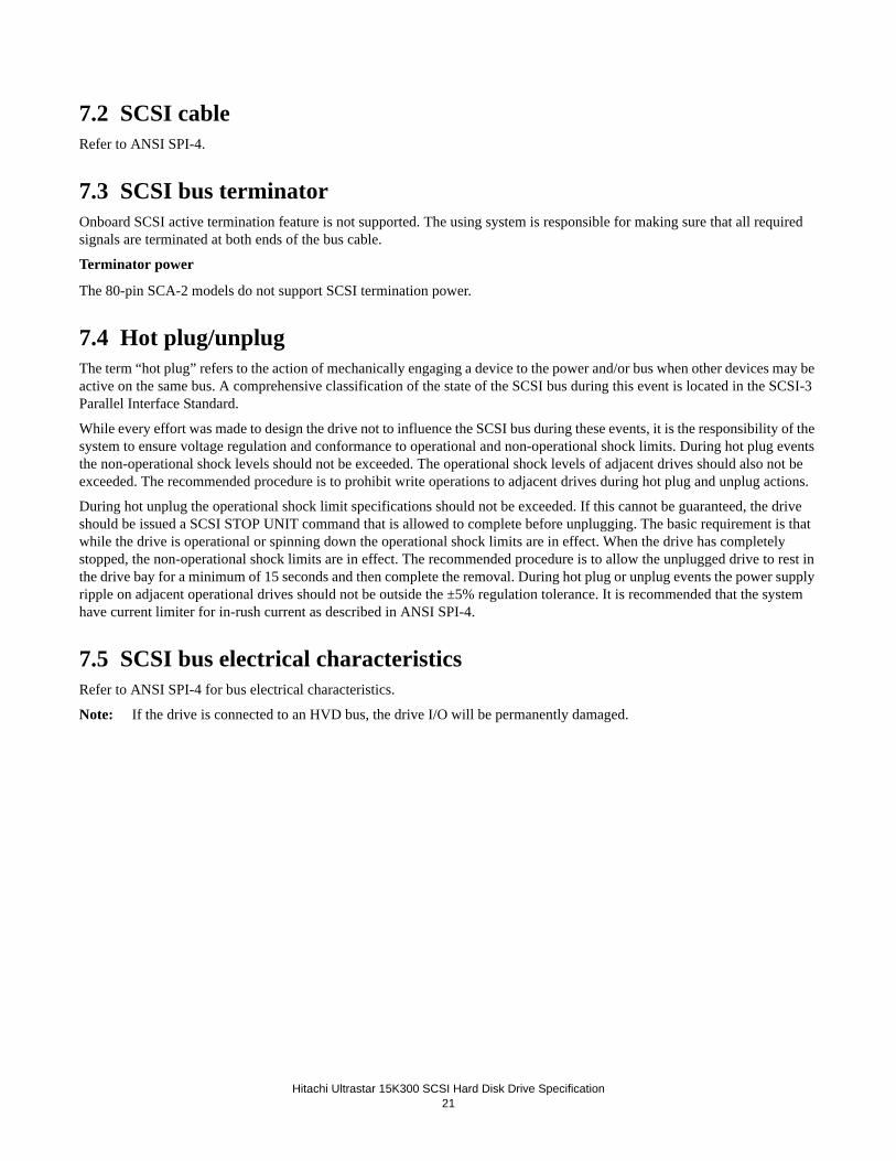
7.2 SCSI cableRefer to ANSI SPI-4.
7.3 SCSI bus terminatorOnboard SCSI active termination feature is not supported. The using system is responsible for making sure that all required signals are terminated at both ends of the bus cable.
Terminator power
The 80-pin SCA-2 models do not support SCSI termination power.
7.4 Hot plug/unplugThe term “hot plug” refers to the action of mechanically engaging a device to the power and/or bus when other devices may be active on the same bus. A comprehensive classification of the state of the SCSI bus during this event is located in the SCSI-3 Parallel Interface Standard.
While every effort was made to design the drive not to influence the SCSI bus during these events, it is the responsibility of the system to ensure voltage regulation and conformance to operational and non-operational shock limits. During hot plug events the non-operational shock levels should not be exceeded. The operational shock levels of adjacent drives should also not be exceeded. The recommended procedure is to prohibit write operations to adjacent drives during hot plug and unplug actions.
During hot unplug the operational shock limit specifications should not be exceeded. If this cannot be guaranteed, the drive should be issued a SCSI STOP UNIT command that is allowed to complete before unplugging. The basic requirement is that while the drive is operational or spinning down the operational shock limits are in effect. When the drive has completely stopped, the non-operational shock limits are in effect. The recommended procedure is to allow the unplugged drive to rest in the drive bay for a minimum of 15 seconds and then complete the removal. During hot plug or unplug events the power supply ripple on adjacent operational drives should not be outside the ±5% regulation tolerance. It is recommended that the system have current limiter for in-rush current as described in ANSI SPI-4.
7.5 SCSI bus electrical characteristicsRefer to ANSI SPI-4 for bus electrical characteristics.
Note: If the drive is connected to an HVD bus, the drive I/O will be permanently damaged.

Hitachi Ultrastar 15K300 SCSI Hard Disk Drive Specification
22
7.6 Option jumper blockAs shown in the figure below, the 80 pin SCA-2 card has a single jumper block ( J6).
As described in Section 7.2.2, “SCSI signal connector (80-pin SCA-2 model)” on page 31, some of the jumper pins on J6 ofthe 80-pin models can also be controlled through the 80-pin SCA-2 connector. These controls work as a logical OR betweenthe Option Jumper Block and the SCA-2 connector.

Hitachi Ultrastar 15K300 SCSI Hard Disk Drive Specification23
7.7 Jumper signal Description on 80 pin Jumper Block
7.7.1 Disable Auto Spin (position 1-2)If a jumper is not installed, the drive will spin up automatically after the power on reset. If a jumper is installed, thedrive will not spin up unless a START UNIT command is received.
7.7.2 Auto Spin Delay and Delay Spin 12 / 6 (position 3-4 and position 5-6)These pins control when and how the drive spins up with the combination of Position #1-2 on J6. When both Auto Spin up and Auto Start Delay are enabled, the drive start will be delayed by a period of time multiplied by its own SCSI address. If Auto Spin up is disabled, these jumpers will be ignored. Placing a jumper on delay start 12 / 6 results in a start up delay of 12 sec-onds time the SCSI ID.
Note: In the table below, “on” means a jumper is installed and “off” means that a jumper is not installed.
Table 14: Auto start delay & delay start 6/12 drive behavior
7.7.3 Force Single Ended Mode (position 7-8)If a jumper is installed, the drive functions as a single-ended mode drive.
7.7.4 Reserved (position 9-10)No connection should be made.

Hitachi Ultrastar 15K300 SCSI Hard Disk Drive Specification
24
7.7.5 LED Driver Out (position 11-12)The LED pins are used to drive an external Light Emitting Diode. Up to 30 mA of sink current capability is provided. TheLED Anode must be tied to the current limited +5V source provided at the Location #11 on J6 jumper block. The LED Cathode is then connected to pin #12 on J6 jumper block to complete the circuit.

Hitachi Ultrastar 15K300 SCSI Hard Disk Drive Specification
25
8.0 Environment
8.1 Temperature and humidityTable 15: Operating and non-operating conditions
Operating conditions
Ambient Temperature 5°C to 55ºC (see note)
Relative humidity 5 to 90%, non-condensing
Maximum wet bulb temperature 29.4ºC, non-condensing
Maximum temperature gradient 20ºC/hour
Altitude -305 to 3,048 m
Shipping conditions
Ambient Temperature -40°C to70ºC
Relative humidity 5 to 95%, non-condensing
Maximum wet bulb temperature 35ºC, non-condensing
Maximum temperature gradient 30ºC/hour
Altitude -305 to 12,192 m
Storage conditions
Ambient Temperature 0°C to 65ºC
Relative humidity 5 to 90%, non-condensing
Maximum wet bulb temperature 35ºC, non-condensing
Altitude -305 to 12,192 m

Hitachi Ultrastar 15K300 SCSI Hard Disk Drive Specification
26
8.2 Storage requirements
8.2.1 PackagingThe drive or option kit must be heat-sealed in a moisture barrier bag with dessiccant inside the bag supplied by Hitachi Global Storage Technologies.
8.2.2 Storage timeCumulative storage time in the package must not exceed one year. If a longer storage time is required, the drive must be repackaged with new desiccant or moved to a climatically controlled environment.
After the drive is unpackaged, it must not remain inoperative for longer than six months.
8.3 Corrosion testThe hard disk drive shows no signs of corrosion inside or outside of the hard disk assembly and remains functional after being exposed to a temperature of 50ºC and relative humidity of 90% for seven days.
0
10
20
30
40
50
60
70
80
90
100
-45 -35 -25 -15 -5 5 15 25 35 45 55 65Temperature ('C)
Rel
ativ
e H
umid
ity (%
)
Non-operating
Operating
WetBuib=29.4'C
WetBuib=35.0'C
65'C/14%
55'C/15%
31'C/90%
36'C/95%

Hitachi Ultrastar 15K300 SCSI Hard Disk Drive Specification
27
8.4 Cooling requirementsDrive component surface temperatures must remain within the limits specified in the following table. The drive may require forced air cooling to meet specified operating temperatures.
Table 16: Maximum allowable surface temperatures
Module name Location Maximum allowable surface temperatureMPU/HDC Integration module 1 108ºCDRAM 2 85ºCVCM & spindle driver 3 108ºCChannel 4 115ºCHDD base casting as noted in picture 60ºC

Hitachi Ultrastar 15K300 SCSI Hard Disk Drive Specification
28

Hitachi Ultrastar 15K300 SCSI Hard Disk Drive Specification
29
9.0 DC power requirementsThe following voltage specification applies at the drive power connector. Connections to the drive should be made in a safety extra low voltage (SELV) circuit. There is no power on or power off sequencing requirement.
Adequate secondary over-current protection is the responsibility of the system. A 10 A limit is required for safety purposes.
Table 17: Input voltage
1. -8% of 12V voltage margin is acceptable during spin-up, but the drive ready time as specified in section 4.5.2 is not guar-anteed.
CAUTION: To avoid damage to the drive electronics, power supply voltage spikes must not exceed 5.5V.
Tolerance Absolute max spike voltage Supply rise time
+5 Volts supply +/- 5% 5.5 V 0-200 ms+12 Volts supply +/- 5%, 1 15 V 0-400 ms
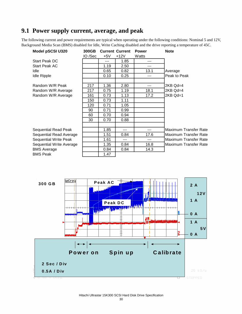
Hitachi Ultrastar 15K300 SCSI Hard Disk Drive Specification
30
9.1 Power supply current, average, and peakThe following current and power requirements are typical when operating under the following conditions: Nominal 5 and 12V,Background Media Scan (BMS) disabled for Idle, Write Caching disabled and the drive reporting a temperature of 45C.
Model pSCSI U320 300GB Current Current Power NoteIO /Sec +5V +12V Watts
Start Peak DC --- 1.85 --- Start Peak AC 1.19 2.50 --- Idle 0.65 0.82 13.1 AverageIdle Ripple 0.10 0.25 --- Peak to Peak Random W/R Peak 217 1.36 2.80 --- 2KB Qd=4Random W/R Average 217 0.75 1.19 18.1 2KB Qd=4Random W/R Average 161 0.73 1.13 17.2 2KB Qd=1 150 0.73 1.11 120 0.71 1.05 90 0.71 0.99 60 0.70 0.94 30 0.70 0.88 Sequential Read Peak 1.85 --- --- Maximum Transfer RateSequential Read Average 1.51 0.84 17.6 Maximum Transfer RateSequential Write Peak 1.61 --- --- Maximum Transfer RateSequential Write Average 1.35 0.84 16.8 Maximum Transfer RateBMS Average 0.84 0.84 14.3 BMS Peak 1.47
S p in u p C a lib ra teP o w er o n
2 A
1 A
0 A
0 A
1 A5 V
1 2V
2 S ec / D iv
0 .5 A / D iv
P eak D C
P eak A C300 G B
S p in u p C a lib ra teP o w er o n
2 A
1 A
0 A
0 A
1 A5 V
1 2V
2 S ec / D iv
0 .5 A / D iv
P eak D C
P eak A C300 G B
S p in u p C a lib ra teP o w er o n
2 A
1 A
0 A
0 A
1 A5 V
1 2V
2 S ec / D iv
0 .5 A / D iv
P eak D C
P eak A C300 G B

Hitachi Ultrastar 15K300 SCSI Hard Disk Drive Specification
31
Model pSCSI U320 147GB Current Current Power NoteIO /Sec +5V +12V Watts
Start Peak DC --- 1.85 --- Start Peak AC 1.19 2.50 --- Idle 0.65 0.54 9.7 AverageIdle Ripple 0.10 0.25 --- Peak to Peak Random W/R Peak 217 1.33 2.80 --- 2KB Qd=4Random W/R Average 217 0.74 0.93 14.9 2KB Qd=4Random W/R Average 161 0.73 0.83 13.6 2KB Qd=1 150 0.73 0.81 120 0.71 0.76 90 0.71 0.70 60 0.70 0.65 30 0.70 0.59 Sequential Read Peak 1.78 --- --- Maximum Transfer RateSequential Read Average 1.49 0.56 14.2 Maximum Transfer RateSequential Write Peak 1.59 --- --- Maximum Transfer RateSequential Write Average 1.38 0.56 13.6 Maximum Transfer RateBMS Average 0.83 0.56 10.9 BMS Peak 1.41
Model pSCSI U320 73GB Current Current Power NoteIO /Sec +5V +12V Watts
Start Peak DC --- 1.85 --- Start Peak AC 1.19 2.50 --- Idle 0.65 0.41 8.2 AverageIdle Ripple 0.10 0.19 --- Peak to Peak Random W/R Peak 217 1.33 2.80 --- 2KB Qd=4Random W/R Average 217 0.74 0.79 13.2 2KB Qd=4Random W/R Average 161 0.73 0.71 12.1 2KB Qd=1 150 0.73 0.69 120 0.71 0.63 90 0.71 0.58 60 0.70 0.52 30 0.70 0.47 Sequential Read Peak 1.82 --- --- Maximum Transfer RateSequential Read Average 1.48 0.43 12.6 Maximum Transfer RateSequential Write Peak 1.61 --- --- Maximum Transfer RateSequential Write Average 1.36 0.43 12.0 Maximum Transfer RateBMS Average 0.83 0.43 9.3 BMS Peak 1.46

Hitachi Ultrastar 15K300 SCSI Hard Disk Drive Specification
32
9.2 Ripple voltageTable 18: Power supply generated ripple at drive power connector
During drive start up and seek, 12 volt ripple is generated by the drive (referred to as dynamic loading). If the power of several drives is daisy chained, the power supply ripple plus other drive dynamic loading must remain within the regulation tolerance of +5%. A common supply with separate power leads to each drive is a more desirable method of power distribution.
To prevent external electrical noise from interfering with the drive's performance, the drive must be held by four screws in a user system frame that has no electrical level difference at the four screw positions. The drive enclosure must not be used in the current return path of the drive power supply. The maximum common-mode noise current passing through the drive must not exceed 20 mA.
9.3 Power consumption efficiency indexTable 19: Power consumption efficiency index
Maximum (mV pp) MHz+5 V DC 250 0-10
+12 V DC 250 0-10
Model 300 GB 147GB 73 GBPower consumption efficiency index (W/GB) 0.044 0.066 0.112

Hitachi Ultrastar 15K300 SCSI Hard Disk Drive Specification
33
10.0 Reliability
10.1 Start/stop cyclesThe drive is designed to withstand a minimum of 50,000 start/stop cycles at ambient environment.
The drive is designed to withstand a minimum of 10,000 start/stop cycles at the operating environment conditions specified in "Enviornment" on page 36.
10.2 Data reliabilityThe probability of an uncorrectable data error is 1 in 1016 bits read.
The following ECC On-The-Fly (OTF) correction is implemented:
• 1 symbol = 10 bits
• 1 interleave
• 20 symbols, On-The-Fly correction
• Up to 38 symbols (total) Off-Line correction with burst error information
• LBA seeded 32 bit CRC for ECC miscorrect detection
10.3 Seek errorsA non-recoverable seek/ID miscompare error is defined as a seek operation that cannot be recovered by the error recovery pro-cedure of the drive. The drive reports sense key 04 and sense code 02 for this error.
No drive has more than one non-recoverable seek/ID miscompare error per 100 million seek operations (1 in 1x 10⁸) when operated at the full range of voltage and environmental conditions.
10.4 Failure prediction (PFA/S.M.A.R.T)A recoverable equipment error is an error other than a seek/ID miscompare error or read error that is detected and corrected by the drive error recovery procedure. Examples are Write Fault, Drive Not Ready and internal drive errors.
No drive has more than one recoverable equipment error per 108 READ, 108 WRITE, or 106 SEEK operations when operated at the full range of voltage and environmental conditions.
Non-recoverable equipment errors indicate a defective drive.
10.5 Preventive maintenanceNone.
10.6 Temperature warningTemperature warning is enabled by setting the EWASC (Enable Warning additional sense code) bit to 1 and setting DEXCPT (Disable Exception Control) bit to 0 in Mode Page 1C. For mode page settings, refer to Section 17.11.13, “Mode page 1C (Informational exceptions control)” on page 152. The warning is issued as sense data (Sense Key 01h, Code 0Bh, Qual 01h).
The drive temperature is reported in Log Sense page 2F. Refer to Section 17.7.11, “Log Sense page 2F” on page 111.

Hitachi Ultrastar 15K300 SCSI Hard Disk Drive Specification
34

Hitachi Ultrastar 15K300 SCSI Hard Disk Drive Specification
35
11.0 Mechanical specifications11.1 Outline11.1.0.1 80-pin connector model
11.2 Mechanical dimensionsThe drive complies with SFF-8301.
Table 20: Physical dimensions
Height [mm] 25.8 ± 0.3
Width [mm] 101.6 ± 0.25
Length [mm] 146.2 ± 0.8
Weight [grams - maximum] 300 GB Model 745 grams
147 GB Model 714 grams
73 GB Model 699 grams

Hitachi Ultrastar 15K300 SCSI Hard Disk Drive Specification36
101.6 ±0.25
146.2±0.8
25.8 ±0.3

Hitachi Ultrastar 15K300 SCSI Hard Disk Drive Specification
37
11.3 Interface connector - 80 pinTable 21: Interface connector - 80 pin
4.6±0.7
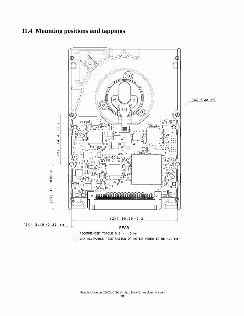
Hitachi Ultrastar 15K300 SCSI Hard Disk Drive Specification38
11.4 Mounting positions and tappings
REARRECOMMENDED TORQUE 0.8 - 1.0 Nm
MAX ALLOWABLE PENETRATION OF NOTED SCREW TO BE 4.0 mm1
44.45±0.2
(2x)
41.28±0.2
(2x)
95.25 ±0.2(2X)
3.18 ±0.25(2X) mm
(4X) 6-32 UNC

Hitachi Ultrastar 15K300 SCSI Hard Disk Drive Specification
39
11.4.0.1 Mounting positions and tappings
28.6±0.2
(2x)
41.6±0.2
(2x)
60±0.2
(2x)
6.35(6x)

Hitachi Ultrastar 15K300 SCSI Hard Disk Drive Specification40
11.5 Drive mountingThe drive will operate in all axes (six directions). Performance and error rate will stay within specification limits if the drive is operated in the other orientations from which it was formatted.
The recommended mounting screw torque is 0.6 - 1.0 Nm (6 - 10 kgf-cm). The recommended mounting screw depth is 4 mm maximum for bottom and 4.5 mm maximum for horizontal mounting.
To avoid performance degradation, mount the drive in the system securely enough to prevent excessive motion or vibration of the drive at seek operation or spindle rotation, using appropriate screws or equivalent mounting hardware. Consult with the issuer of this specification for actual application if necessary.
Drive level vibration tests and shock tests are to be conducted with the drive mounted to a table using the bottom four screws.
11.6 Heads unload and actuator lockHeads are moved out from the disks (unload) to protect the disk data during shipping, moving, or storage. At power down, the heads are automatically unloaded from over the disk area and the head actuator locking mechanism will secure the heads in the unload position.

Hitachi Ultrastar 15K300 SCSI Hard Disk Drive Specification41
12.0 Vibration and shockAll vibration and shock measurements in this section are made with a bare drive. The input for the measurements are applied to the normal drive mounting points unless noted otherwise.
12.1 Operating vibration
12.1.1 Random vibrationThe drive is designed to operate without unrecoverable errors while being subjected to the vibration levels defined below.
The assessments are carried out during 30 minutes of random vibration using the power spectral density (PSD) levels as fol-lows.
No Errors: 0.4 G RMS, 5-500 Hz, flat PSD profile for each of the three mutually perpendicular axes.
No Data Loss: 1.2 G RMS, 5-500 Hz, flat PSD profile for each of the three mutually perpendicular axes.
Note: The specified levels are measured at the mounting points.
12.1.2 Swept sine vibrationThe drive will meet the criterion while operating in the respective conditions as described below.
No errors: 0.5 G 0-peak, 5-400-5 Hz sine wave, 0.5 octave/minute sweep rate
No data loss: 1.5 G 0-peak, 5-500-5 Hz sine wave, 0.5 octave/minute sweep rate
12.2 Non-operating vibrationThe drive will not sustain permanent damage or loss of recorded data after being subjected to the environments as described below.
12.2.1 Random vibrationThe test consists of a random vibration applied for each of the three mutually perpendicular axes at a time duration of ten min-utes per axis:
1.04 G RMS, 5-500 Hz, flat PSD profile
12.2.2 Swept sine vibrationThe test consists of a swept sine vibration applied for each of the three mutually perpendicular axes.
2.0G 0-peak, 5-500-5 Hz sine wave, 0.5 octave/minute sweep rate
12.3 Operating shockThe drive will meet the criterion while operating in the respective conditions as described below.
No data loss: 15G, 11 ms duration, half sinewave shock pulse
No data loss: 30G, 2 ms duration, half sinewave shock pulse
The shock pulses of each level are applied to the drive, ten pulses for each direction and for all three mutually perpendicular axes. There must be a minimum of 30 seconds delay between shock pulses. The input level is applied to a base plate where the drive is attached using four mounting screws.

Hitachi Ultrastar 15K300 SCSI Hard Disk Drive Specification
42
12.4 Non-operating shockThe drive will not sustain permanent damage or loss of recorded data after being subjected to the environments as described below.
12.4.1 Half sinewave shock pulse80 G, 11 ms duration, half sinewave pulse
250 G, 2 ms duration, half sinewave pulse
The shocks are applied in each direction of the drive for the three mutually perpendicular axes, one axis at a time. The input level is applied to a base plate where the drive is attached using four mounting screws.
12.4.2 Rotational shock 30,000 radians/second2, 1 ms duration
20,000 radians/second2, 2 ms duration
The shock input is applied around the axis of the actuator pivot. The shock input does not displace the heads from the actuator latched position.

Hitachi Ultrastar 15K300 SCSI Hard Disk Drive Specification43
13.0 Acoustics
13.1 Sound power levelsThe upper limit criteria of A-weighted sound power levels are given in Bel, relative to one pico watt, and are shown in the following table. The measurement method is in accordance with ISO-7779.
Table 22: A-weighted sound power levels
Background power levels of the acoustic test chamber for each octave band are to be recorded. Sound power levels are mea-sured with the drive supported by spacers so that the lower surface of the drive is located at a height of 25 cm from the cham-ber floor.No sound-absorbing material shall be used. The acoustical characteristics of the drive subsystem are measured under thefollowing conditions.
Idle Mode:Powered on, disks spinning, track following, unit ready to receive and respond to host commands.
Operating Mode:
Continuous random cylinder selection and seek operation of the actuator with dwell time at each cylinder. Seek rate for the drive is calculated per the formula below:
Ns =average seek rate in seeks/sec where:
Ns = 0.4 / (Tt + Tl)
Tt = published random seek time
Tl = time for the drive to rotate by half a revolution
Model ModeA-weighted sound power level (Bel)
Typical Maximum
300 GBIdle 3.5 3.8
Operating 4.3 4.7
147 GB Idle 3.5 3.8
Operating 4.3 4.7
73 GB Idle 3.5 3.8
Operating 4.3 4.7

Hitachi Ultrastar 15K300 SCSI Hard Disk Drive Specification44

Hitachi Ultrastar15K300 SCSI Hard Disk Drive Specification45
14.0 Identification
14.1 LabelsThe following labels are affixed to every hard disk drive shipped from the drive manufacturing location in accordance with appropriate hard disk drive assembly drawing:
• A label containing Hitachi logo, Hitachi part number, and the statement “Made by Hitachi”, or Hitachi approved equivalent.
• A label containing drive model number, manufacturing date, formatted capacity, country of origin or Hitachi approved equivalent and UL, C-UL, TUV, CE, MIC, BSMI,CTICK, RoHS and Recycle logos.
• A bar code label containing the drive serial number.
• Jumper setting label.
• A user designed label, per agreement.
• Interface definition mark, SCSI LVD/SE multimode.
The labels may be integrated with other labels.
SCSI LVD/SE

Hitachi Ultrastar 15K300 SCSI Hard Disk Drive Specification46

Hitachi Ultrastar 15K300 SCSI Hard Disk Drive Specification
47
15.0 Electromagnetic CompatibilityThe drive, when installed in a suitable enclosure and exercised with a random accessing routine at a maximum data rate willcomply with the worldwide EMC requirements listed below.
The drive is designed for system integration and installation into a suitable enclosure for use. As such, the drive is supplied as a subassembly and is not subject to Subpart B of Part 15 of the FCC Rules and Regulations.
The design of the drive serves to minimize radiated emissions when installed in an enclosure that provides reasonable shield-ing. As such, the drive is capable of meeting FCC Class B limits. However, it is the users responsibility to assure that the drive meets the appropriate EMC requirements in their system. Shielded I/O cables may be required if the enclosure does not provide adequate shielding, with the shields grounded to the enclosure and to the host computer.
Radiated and Conducted EMI
CISPR22 Class B
AS/NZS CISPR22 Class B
CNS13438 (Taiwan) Class B
EN55022 (EU) Class B
FCC Title47 Part 15 (USA) Class B
GB9254 (China) Class B
ICES-003, Issue 4 Class B
VCCI (Japan) Class B
ITE Immunity
EN55024
Power Line Harmonics
EN61000-3-2 (EU)
Voltage Fluctuations and Flicker
EN61000-3-3 (EU)
15.1 Class B Regulatory NoticesEuropean UnionThis product is in conformity with the protection requirements of EU Council Directive 89/336/EEC, as amended by Council Directive 93/68/EEC on the approximation of the laws of the Member States relating to electromagnetic compatibility. Hitachi cannot accept responsibility for any failure to satisfy the protection requirements resulting from a non-recommended modifica-tion of the product, including the fitting of non-Hitachi option cards.
This product has been tested and found to comply with the limits for Class B Information Technology Equipment according to European Standard EN 55022. The limits for Class B equipment were derived for typical residential environments to provide reasonable protection against interference with licensed communication devices.

Hitachi Ultrastar 15K300 SCSI Hard Disk Drive Specification
48
CanadaThis Class B digital apparatus complies with Canadian ICES-003.Cet appareil numérique de la classe B est conforme à la norme NMB-003 du Canada.
GermanyDeutschsprachiger EU Hinweis: Hinweis für Geräte der Klasse B EU-Richtlinie zur Elektromagnetischen Verträglichkeit Dieses Produkt entspricht den Schut-zanforderungen der EU-Richtlinie 89/336/EWG zur Angleichung der Rechtsvorschriften über die elektromagnetische Ver-träglichkeit in den EU-Mitgliedsstaaten. und hält die Grenzwerte der EN 55022 Klasse B ein. Um dieses sicherzustellen, sind die Geräte wie in den Handbüchern beschrieben zu installieren und zu betreiben. Des Weiteren dürfen auch nur von der HITA-CHI empfohlene Kabel angeschlossen werden. HITACHI übernimmt keine Verantwortung für die Einhaltung der Schutzan-forderungen, wenn das Produkt ohne Zustimmung der HITACHI verändert bzw. wenn Erweiterungskomponenten von Fremdherstellern ohne Empfehlung der HITACHI gesteckt/eingebaut werden.
Deutschland: Einhaltung des Gesetzes über die elektromagnetische Verträglichkeit von Geräten Dieses Produkt entspricht dem "Gesetz über die elektromagnetische Verträglichkeit von Geräten (EMVG)". Dies ist die Umsetzung der EU-Richtlinie 89/336/EWG in der Bundesrepublik Deutschland.
Zulassungsbescheinigung laut dem Deutschen Gesetz über die elektromagneti-sche Verträglichkeit von Geräten (EMVG) vom 18. September 1998 (bzw. der EMC EG Richtlinie 89/336) für Geräte der Klasse B Dieses Gerät ist berechtigt, in Übereinstim-mung mit dem Deutschen EMVG das EG-Konformitätszeichen - CE - zu führen. Verantwortlich für die Konformitätserk-lärung nach Paragraf 5 des EMVG ist die Hitachi Global Storage Technologies , 5600 Cottle road, San Jose, California 95193. Informationen in Hinsicht EMVG Paragraf 4 Abs. (1) 4:
Das Gerät erfüllt die Schutzanforderungen nach EN 55024 und EN 55022 Klasse B.
Korea (MIC)
Taiwan (BSMI)

Hitachi Ultrastar 15K300 SCSI Hard Disk Drive Specification49
16.0 StandardsThe following shows the safety standards for different countries.
16.1 UL and CSA standard conformityThe drive is qualified per ULIEC 60950-1: 2001, First Edition for use in Information Technology Equipment, including Elec-tric Business Equipment. The UL recognition, or the CSA certification, is maintained for the product life. The UL and C-UL recognition mark, or CSA monogram for CSA certification, appears on the drive.
16.2 European standards complianceThe product is certified to EN60950.
16.3 German safety markThe product is approved by the TUV and will carry the applicable Bauart mark on the label.
16.4 FlammabilityThe printed circuit boards used in this drive are made of material with a UL recognized flammability rating of V-1 or better. The flammability rating is marked or etched on the board. All other parts not considered electrical components are made of material with a UL recognized flammability rating of V-1 or better.
16.5 Corporate Standards Compliance This product has been designed to meet the following Corporate Standards:
- NB 3-0501-201 Product Safety, National Requirements-All Countries. - CS 3-0501-070 Electrical, Mechanical and Flammability - NB 3-0501-033 Product Safety National Certification Conformity Requirement - CS 1-9700-020 Eco-Product Design Requirement
Hitachi GST encourages owners of information technology (IT) equipment to responsibly recycle their equipment when it is no longer needed. Hitachi GST offers a variety of programs and services to assist equipment owners in recycling their IT products.

Hitachi Ultrastar 15K300 SCSI Hard Disk Drive Specification
50

Hitachi Ultrastar 15K300 (SCSI) Hard Disk Drive Specification
51
17.0 SCSI Command SetSummaries of the SCSI commands supported by the drive are listed below. O = optional, M = mandatory
Table 23: SCSI Commands Supported
Type Code Description M 04h FORMAT UNIT (04), page 54 M 12h INQUIRY (12), page 61O 4Ch LOG SELECT (4C), page 72 O 4Dh LOG SENSE (4D), page 75O 15h MODE SELECT (15), page 100O 55h MODE SELECT (55), page 101O 1Ah MODE SENSE (1A), page 102O 5Ah MODE SENSE (5A), page 137 O 5Eh PERSISTENT RESERVE IN (5E), page 139O 5Fh PERSISTENT RESERVE OUT (5F), page 142O 34h PRE-FETCH (34), page 147M 08h READ (6) - (08), page 148M 28h READ (10) - (28), page 149O A8h READ (12) - (A8), page 151O 88h READ (16) - (88), page 152O 3Ch READ BUFFER (3C), page 153M 25h READ CAPACITY (10) - (25), page 157O 9Eh/10h READ CAPACITY (16) (9E/10), page 159O 37h READ DEFECT DATA (37), page 160O B7h READ DEFECT DATA (B7), page 164O 3Eh READ LONG (3E), page 166O 07h REASSIGN BLOCKS (07), page 167O 1Ch RECEIVE DIAGNOSTICS RESULTS (1C), page 169M 17h RELEASE (17), page 172O 57h RELEASE (57), page 173O A3h/05h REPORT DEVICE IDENTIFIER (A3/05), page 174O A0h REPORT LUNS (A0), page 176
O A3h/0Ch REPORT SUPPORTED OPERATION CODES (A3/0C), page 177
O A3h/0Dh REPORT SUPPORTED TASK MANAGEMENT FUNCTIONS (A3/0D), page 180
M 03h REQUEST SENSE (03), page 182M 16h RESERVE (16), page 183O 56h RESERVE (56), page 184O 01h REZERO UNIT (01), page 185O 0Bh SEEK (6) - (0B), page 186O 2Bh SEEK (10) - (2B), page 186M 1Dh SEND DIAGNOSTIC (1D), page 187O A4h/06h SET DEVICE IDENTIFIER (A4/06), page 191O 1Bh START STOP UNIT (1B), page 192O 35h SYNCHRONIZE CACHE (10) - (35), page 193

Hitachi Ultrastar 15K300 (SCSI) Hard Disk Drive Specification
52
O 91h SYNCHRONIZE CACHE (16) - (91), page 194M 00h TEST UNIT READY (00), page 195O 2Fh VERIFY (2F), page 196O AFh VERIFY (12) - (AF), page 199O AFh VERIFY (16) - (8F), page 200M 0Ah WRITE (6) - (0A), page 201M 2Ah WRITE (10) - (2A), page 202O AAh WRITE (12) - (AA), page 205O 8Ah WRITE (16) - (8A), page 206O 2Eh WRITE AND VERIFY (10) - (2E), page 207O AEh WRITE AND VERIFY (12) - (AE), page 208O 8Eh WRITE AND VERIFY (16) - (8E), page 209O 3Bh WRITE BUFFER (3B), page 210O 3Fh WRITE LONG (3F), page 214O 41h WRITE SAME (41), page 215O 93h WRITE SAME (16) - (93), page 216
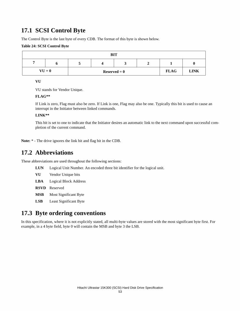
Hitachi Ultrastar 15K300 (SCSI) Hard Disk Drive Specification
53
17.1 SCSI Control ByteThe Control Byte is the last byte of every CDB. The format of this byte is shown below.
Table 24: SCSI Control Byte
VU
VU stands for Vendor Unique.
FLAG**
If Link is zero, Flag must also be zero. If Link is one, Flag may also be one. Typically this bit is used to cause an interrupt in the Initiator between linked commands.
LINK**
This bit is set to one to indicate that the Initiator desires an automatic link to the next command upon successful com-pletion of the current command.
Note: * - The drive ignores the link bit and flag bit in the CDB.
17.2 AbbreviationsThese abbreviations are used throughout the following sections:
LUN Logical Unit Number. An encoded three bit identifier for the logical unit.
VU Vendor Unique bits
LBA Logical Block Address
RSVD Reserved
MSB Most Significant Byte
LSB Least Significant Byte
17.3 Byte ordering conventionsIn this specification, where it is not explicitly stated, all multi-byte values are stored with the most significant byte first. For example, in a 4 byte field, byte 0 will contain the MSB and byte 3 the LSB.
BIT
7 6 5 4 3 2 1 0
VU = 0 Reserved = 0 FLAG LINK

Hitachi Ultrastar 15K300 (SCSI) Hard Disk Drive Specification
54
17.4 FORMAT UNIT (04)Table 25: FORMAT UNIT (04)
• FMTPINFO (Format Protection Information) set to zero specifies that the drive shall disable the use of protection information and format to the block size specified. FMTPINFO set to one specifies that the drive shall enable the use of protection information and format to the block size specified + 8 (e.g., if the block length is 512, then the format-ted block length is 520). Following a successful format, the PROT_EN bit in the READ CAPACITY (16) parameter data indicates whether protection information is enabled. When protection information is written during a FORMAT UNIT command (i.e., the FMTPINFO bit is set to one), protection information shall be written with a default value of all FF's.
• RTO_REQ (Reference Tag Own Request) specifies whether the initiator or drive has ownership of the Logical Block Reference Tag field in protection information. If the FMTPINFO bit is set to zero and the RTO_REQ bit is set to one, Check Condition status will be returned, with the sense key set to Illegal Request and the additional sense code set to Invalid Field in CDB. If the FMTPINFO bit is set to one and the RTO_REQ bit is set to one, application client ownership of the Logical Block Reference Tag field is enabled, (i.e. the initiator owns the Logical Block Reference Tag field). If the FMT-PINFO bit is set to one the the RRTO_REQ bit is set to zero, application client ownership of the Logical Block Refer-ence Tag field is disabled (i.e. the drive owns the Logical Block Reference Tag field). Following a successful format, the RTO_EN bit in the READ CAPACITY (16) parameter data indicates whether application client ownership of the Logical Block Reference Tag field is enabled.
• FmtData set to one specifies that a Data Out phase follows the Command phase. The Data Out phase consists of a Parameter List header, optionally followed by an Initialization Pattern Descriptor, optionally followed by a Defect List. If FmtData=0, the following defaults are assumed: DPRY=0, DCRT=1, STPF=1, IP=0, DSP=0, Immed=0.
• CmpLst • - set to one specifies that the Grown Defect List (GList) existing prior to the issuance of the Format Unit command be discarded. If provided, the DList then becomes the GList. Following these operations, the Drive will be formatted with the PList and GList.• - set to zero specifies that the GList existing prior to the issuance of the Format Unit command is retained. If pro-vided, the DList is combined with the GList to become the new GList. Following these operations, the Drive will be formatted with the PList and GList.
Note: The drive manages two internal defect lists and one external. The Plist is created at time of manufacture. The Glist is built after manufacture by the Initiators’ use of the REASSIGN BLOCK command and the Automatic Reallocate functions. The Dlist is an external list. It is supplied by the Initiator in the Data Out phase of the FORMAT UNIT command.
• Defect List Format specifies the format of the defect descriptor transferred to the Target when FmtData bit is set to one. The Target supports the following three defect descriptor formats for the FORMAT UNIT command:
Byte BIT
7 6 5 4 3 2 1 0
0 Command Code = 04h
1 FMTPINFO RTO_REQ LONGLIST=0
FMT-DATA CMPLIST Defect List Format
2 VU = 0
3-4 Obsolete = 0
5 VU = 0 Reserved = 0 FLAG LINK

Hitachi Ultrastar 15K300 (SCSI) Hard Disk Drive Specification
55
Format Description
000b Block format
100b Bytes From Index format
101b Physical Sector format
If the FmtData bit is set to zero, this field must also be zero. Otherwise the command will complete with a CHECK CONDITION with a sense key of Illegal Request and an additional sense code of Invalid Field in CDB.
•Notes:It is recommended that the MODE SELECT command be issued prior to the FORMAT UNIT command to specify parameters that affect the formatting process.
The Block Length parameter of the Mode Select Parameter List’s Block Descriptor is used during formatting and is saved following a successful format operation. If a MODE SELECT command has not been issued since the last reset or start-up (bring-up) sequence, then the Block Length from the previous format operation is used.
Subsequent to receiving a FORMAT UNIT command, the Target responds to commands as follows:
- All commands except REQUEST SENSE and INQUIRY return Check Condition status, while the format operation is an active I/O process.
- When tagged queuing is enabled (DQue = 0), all commands except REQUEST SENSE and INQUIRY return Queue Full status, while the FORMAT UNIT command is a queued I/O process.
- When tagged queuing is disabled (DQue = 1), all commands except REQUEST SENSE and INQUIRY return Busy status, while the FORMAT UNIT command is a queued I/O process
- If a REQUEST SENSE command is received while a format operation is an active I/O process, the Target returns Good status. The sense key is set to Not ready and the additional sense code and qualifier is set to Format In Progress.
- If an INQUIRY command is received while a format operation is an active I/O process, the Target returns Good status and Inquiry data as requested.
The format operation must complete successfully for the Drive to be usable. If the command is interrupted by a reset, power down, or an unrecoverable error, the Drive enters a degraded mode of operation in which reading and writing are prohibited. To exit the degraded mode, another FORMAT UNIT command must be sent by the Initiator and com-pleted successfully by the Target.
The FORMAT UNIT command sets the Unit Attention Condition for all Initiators except the one that issued the FOR-MAT UNIT command.

Hitachi Ultrastar 15K300 (SCSI) Hard Disk Drive Specification
56
17.4.1 Parameter List Header Following is the format of the Paramter List Header sent during the data out phase when FmtData is set to one.
Table 26: Format of the Parameter List Header
• FOV (Format Options Valid) bit set to zero indicates that the Target should use its default settings for the DPRY (0),
DCRT (1), STPF (1), IP (0), and DSP (1) bits. These bits must all be set to zero in the Parameter List Header when FOV=0, or the command will be terminated with Check Condition status, sense key of Illegal Request, and addi-tional sense code of Invalid Field in Parameter List.. FOV=1 indicates that the values set in DPRY, DCRT, STPF, IP, and DSP will be defined as specified below.
• DPRY (Disable Primary) bit set to zero indicates that the Target does not use portions of the medium identified as defec-tive in the primary defect Plist for Initiator addressable logical blocks. If the Target cannot locate the Plist or it cannot determine whether a Plist exists, theTarget terminates the FORMAT UNIT command as described for STPF=1. A DPRY bit set to one indicates that the Target does not use the Plist to identify defective areas of the medium. The Plist is not deleted. DPRY must be set to 0 when DCRT is set to 0.
• DCRT (Disable Certification) bit set to zero indicates that the Target performs a medium certification operation and gen-erates a Certification List (Clist), and adds the Clist to the Glist. DPRY must be set to 0 when DCRT is set to 0. A DCRT bit of one indicates that the Target does not generate a Clist or perform a certification process.
Note: Since the DCRT bit is part of the Data Out phase that follows the FORMAT command, the FCERT bit in Mode Page 0 is provided to control certification when the FORMAT command is issued with no Data Out phase. If a FORMAT command is issued with a Data Out phase then FCERT is ignored.
• STPF (Stop Format) bit must be set to one. If one or both of the following conditions occurs, the Target terminates the FORMAT UNIT command with Check Condition status. The sense key is set to Medium Error and the additional sense code is set to Defect List Not Found if the first condition occurred or to Defect List Error if the second condi-tion occurred.
• The Target cannot locate a required Dlist nor determine that the list exists. • The Target encounters an unrecoverable error while accessing a required Dlist. • IP (Initialization Pattern) bit set to zero specifies that an initialization pattern descriptor is not included and all cus-
tomer data will be initialized to zeroes. An IP bit of one specifies that an Initialization Pattern Descriptor is included in the FORMAT UNIT parameter list following the parameter list header.
ByteBIT
7 6 5 4 3 2 1 0
0 Reserved = 0
1 FOV DPRY DCRT STPF=1 IP DSP Immed Ignored
2
3
(MSB) Defect List Length
(LSB)
4-n Initialization Pattern Descriptor
(n+1) - m Defect Descriptor

Hitachi Ultrastar 15K300 (SCSI) Hard Disk Drive Specification
57
Table 27: Initialization Pattern Descriptor:
• IP Modifier must be set to 0, indicating that the drive will not modify the initialization pattern.• SI (Security Initialize) bit set to one specifies that all customer data sectors, including those that have been previously
reassigned, will be initialized. SI set to zero specifies that only the current customer accessible sectors will be for-matted.
• Initialization Pattern Type must be set to one, specifying that the Initialization Pattern specified shall be repeated as required to fill each logical block.
• Initialization Pattern Length specifies the number of bytes that follow in the Initialization Pattern field, and must be less than or equal to the current block size, and non-zero.
• Initialization Pattern contains the data pattern to be written to the media.• DSP (Disable Saving Parameters) bit when zero indicates the target is to save all the current MODE SELECT saveable
parameters during the format operation. When the bit is one, the target is not to save the current MODE SELECT saveable parameters.
• Immed (Immediate) bit set to zero requests that status be returned at the end of the format operation. An immediate bit set to one requests that status be returned immediately following CDB validation and transfer of data in the Data Out phase. If the format operation, with the immediate bit set to one, terminates in error, DEFERRED ERROR SENSE data is generated.
• Defect List Length field specifies the total length in bytes of the defect descriptors that follow (not including the Initial-ization Pattern Descriptor, if any). Up to 1024 defect descriptors are allowed. The Defect List Length must be equal to four times the number of defect descriptors for BLOCK format, or eight times the number of defect descriptors for BYTES FROM INDEX and PHYSICAL SECTOR formats. Otherwise the command is terminated with Check Con-dition status with the sense key set to Illegal Request and the additional sense code set to Invalid Field in Parameter List.
17.4.2 Defect DescriptorThree defect descriptor formats are supported. Entries are not required to be in ascending order. If an entry does not corre-spond to a valid user addressable media location, the command terminates with Check Condition status with the sense key set to Illegal Request and the additional sense code set to Invalide Field in Parameter List.
17.4.2.1 Block Format - 000b
ByteBIT
7 6 5 4 3 2 1 0
0 IP Modifier = 0 SI Reserved = 0
1 Initialization Pattern Type = 1
2 - 3 Initialization Pattern Length (n-3)
4 Initialization Pattern
...
Initialization Pattern
...
n

Hitachi Ultrastar 15K300 (SCSI) Hard Disk Drive Specification
58
Format of the Dlist sent during the data out phase when Dlist Format is Block format (000b) and FmtData is set to one.
Table 28: Defect Descriptor - Block Format (for n + 1 defects)
The Block format of the Dlist is the LBA of each defective sector.
Note: If a Defective LBA entry, when converted to a physical sector, is equal to the physical sector of a Plist entry and DPRY = 1, then the entry is not added to the Glist.
Byte BIT
7 6 5 4 3 2 1 0
0 - 3
(MSB)
Defective Logical Block Address
(LSB)
4n
4n+1
4n+2
4n+3
(MSB)
Defective Logical Block Address n
(LSB)

Hitachi Ultrastar 15K300 (SCSI) Hard Disk Drive Specification
59
17.4.2.2 Bytes From Index Format - 100b
Format of the Dlist sent during the data out phase when Dlist Format is Bytes From Index format (100b) and FmtData is set to one.
Table 29: Defect Descriptor - Bytes From Index Format (for n = 1 defects)
Each defect descriptor for the Bytes From Index format specifies that the sector containing this byte be marked defective. The defect descriptor is comprised of the cylinder number of the defect, the head number of the defect, and the number of the defect byte relative to index.
Note: If a Byte From Index entry, when converted to a physical sector, is equal to the physical sector of a Plist entry and DPRY = 1, then the entry is not added to the Glist.
ByteBIT
7 6 5 4 3 2 1 0
0 - 2
(MSB)
Cylinder Number of Defect
(LSB)
3 Head Number of Defect
4 - 7
(MSB)
Defect Bytes from Index
(LSB)
8n
8n + 1
8n + 2
(MSB)
Cylinder Number of Defect n
(LSB)
8n + 3 Head Number of Defect n
8n + 4
8n + 5
8n + 6
8n + 7
(MSB)
Defect (n) Bytes from Index
(LSB)

Hitachi Ultrastar 15K300 (SCSI) Hard Disk Drive Specification
60
17.4.2.3 Physical Sector Format - 101bFormat of the Dlist sent during the data out phase when Dlist Format is Physical Sector format (101b) and FmtData is set to one.
Table 30: Defect Descriptor - Physical Sector Format (for n + 1 defects)
Each defect descriptor for the Physical Sector format specifies a defective sector. The defect descriptor is comprised of the cyl-inder number of the defect, the head number of the defect, and the defect’s sector number.
Note: If a Physical Sector entry, when converted to a physical sector, is equal to the physical sector of a Plist entry and DPRY = 1, then the entry is not added to the Glist.
ByteBIT
7 6 5 4 3 2 1 0
0
1
2
(MSB)
Cylinder Number of Defect
(LSB)
3 Head Number of Defect
4
5
6
7
(MSB)
Defect Sector Number
(LSB)
8n
8n + 1
8n + 2
(MSB)
Cylinder Number of Defect n
(LSB)
8n + 3 Head Number of Defect n
8n + 4
8n + 5
8n + 6
8n + 7
(MSB)
Defect (n) Sector Number
(LSB)

Hitachi Ultrastar 15K300 (SCSI) Hard Disk Drive Specification
61
17.5 INQUIRY (12)Table 31: INQUIRY (12)
The INQUIRY command requests the parameters of theTarget to be sent to the initiator.
An EVPD bit of one specifies that the Target return the vital product data page identified by the Page Code field in the CDB.
The Page Code specifies which page of vital product data information the drive shall return.
Table 32: Page Code descriptions
Allocation Length specifies the number of bytes that the Initiator has allocated for INQUIRY data to be returned. An alloca-tion length of zero implies that no data is to be returned. The Target will terminate the DATA IN phase when all available INQUIRY data has been transferred or when allocation length bytes have been transferred, whichever is less.
Note: If an INQUIRY command is received from an Initiator with a pending unit attention condition (before the target reports Check Condition status), the Target processes the INQUIRY command. The unit attention condition is not cleared by this action.
Note: The INQUIRY command is a Priority command and is not queued.
Note: The inquiry data is set at the time of manufacture and will not change (without a FRU change), with the following exceptions:
• Product Revision Level (EVPD=0) can be changed when microcode is downloaded with the Write Buffer command. • The information returned for EVPD=1, Page Code = 3 is not fixed.
Note:The inquiry data returned when media is not available will not be complete.Byte 0 of the returned data on an INQUIRY command is the same no matter which page(s) is(are) returned. This description is to be used for all the following page definitions.
The Peripheral Qualifier field of zero (0) indicates that the peripheral device is currently connected to this logical unit. A Peripheral Device Type field of zero (0) indicates that this device is a Direct Access Storage Device (DASD).
Byte BIT
7 6 5 4 3 2 1 0
0 Command Code = 12h
1 Reserved = 0 CmdDt=0 EVPD
2 Page Code
3 - 4 Allocation Length
5 VU = 0 Reserved = 0 FLAG LINK
EVPD PAGE CODE Description
0 0 The Target returns the standard INQUIRY data.
0 Non Zero The drive returns Check Condition status with the sense key of Illegal Request and the additional sense code of Invalid Field in CDB.
1 Non Zero The drive returns the vital product data of page code requested.

Hitachi Ultrastar 15K300 (SCSI) Hard Disk Drive Specification
62
17.5.1 Inquiry DataFields with a value shown inside quotes (e.g. Value =’xyz’) are character fields. A value not in quotes is a numeric value. Character fields are alphanumeric and represented in either ASCII.
17.5.1.1 Inquiry Data Format - EVPD = 0, Page Code = 0
Table 33: Inquiry Data- EVPD = 0
• Qualifier is set to zero to indicate that the LUN specified is currently supported. Qualifier is set to 011b when the LUN specified is not present 1
• Peripheral Device Type is set to zero to indicate that the device is a Direct-Access Peripheral Device.• Removal Media Bit (RMB) is always set to zero to indicate no removal media exists. • Version indicates the level of the ANSI standard that the product supports. The drive supports ANSI SCSI version 3. • NormACA (Normal ACA) field of 0 indicates the device server does not support setting the NACA bit to one in the
Control Byte of the CDB as defined in the SAM. • HiSup bit of 1 indicates that the drive uses the hierarchical addressing model to assign LUNs to logical units.
ByteBIT
7 6 5 4 3 2 1 0
0 Qualifier = 0 Peripheral Device Type = 0
1 RMB = 0 Reserved=0
2 Version = 3
3 Obsolete Obsolete Norm ACA=0 HiSup = 1 Response Data Format = 2
4 Additional Length = 159 (9Fh)
5 SCCS=0 ACC=0 ALUA=00b 3PC=0 Reserved = 0 Protect=1
6 BQue = 0 EncSer = 0 Rsvd=0 MultiP=0 MChngr= 0 Obsolete Addr16 = 1
7 Obsolete Obsolete Wb_16 =1 Sync = 1 Link = 0 Obsolete CmdQue= 1 RSVD = 0
8-15 Vendor ID = "HITACHI " (ASCII)
16-31 Product ID (ASCII)
32-35 Product Revision Level (ASCII)
36-43 Unit Serial Number (ASCII)
44-55 Reserved = 0
56 Reserved = 0 Clock=11b QAS=1 IUS=1
57-95 Reserved=0
96-145 Copyright Notice (ASCII)
146-163 Reserved=0
1.If an INVALID LUN is specified, a Check Condition status will be returned for all commands except INQUIRY and REQUEST SENSE.

Hitachi Ultrastar 15K300 (SCSI) Hard Disk Drive Specification
63
• Response Data Format is set to two to indicate that the INQUIRY Data Format as specified in the ANSI SCSI version 2 is supported by the Target.
• Additional Length indicates the number of bytes of INQUIRY information that follows. • SCCS bit of zero indicates that the device does not contain an embedded storage array controller component.• ACC bit of zero indicates that no access controls coordinator may be addressed through this logical unit.• ALUA bit of zero indicates that the device does not support asymmetric logical unit access.• 3PC bit of zero indicates that the device does not support thrid-party copy commands.• Protect bit of one indicates that the drive supports protection information• BQue bit shall be zero if the CmdQue bit is one.• EncSer (Enclosure Services) bit of 0 indicates that the Target does not contain an embedded enclosure services compo-
nent. •Port bit of 0 indicates that the drive received the Inquiry command on port A, while a Port bit of 1 indicates that the drive
received the Inquiry command on port B.• MultiP (MultiPort) bit of 0 indicates that the Target has a single port and does not implement multi-port requirements. • MChngr (Medium Changer) bit is always 0 to indicate MChngr is not supported. • Addr16 (Wide SCSI Address 16) bit of 1 indicates that the Target supports 16-bit wide SCSI Addresses. • Wb_16 is set to one to indicate that the Target supports 16-bit wide data transfers.• Sync is set to one to indicate that the Target supports synchronous data transfer.• Link is set to zero to indicate that the Target does not support linked commands. • CmdQue is set to one to indicate that the drive supports command queuing. • Vendor ID is HITACHI padded with ASCII blanks. • Product ID is specified in table 3 of Section 4.3.1.• Product Revision Level indicates the level of microcode.• Unit Serial Number contains the drive serial number.

Hitachi Ultrastar 15K300 (SCSI) Hard Disk Drive Specification
64
17.5.1.2 Inquiry Data Format - EVPD = 1 - Page Code = 00hTable 34: Inquiry Data - EVPD = 1 (Page Code = 00h)
• Qualifier is set to zero to indicate that the LUN specified in the Command Block is currently supported. • Peripheral Device Type is set to zero to indicate that the device is Direct Access. • Page Code is set to 0, and this field contains the same value as in the page code field of the INQUIRY command descrip-
tor block. • Page length specifies the length of the following page data. • Supported Page Code field contains the Page Codes supported by the Target. The list is in ascending order.
ByteBIT
7 6 5 4 3 2 1 0
0 Qualifier = 0 Peripheral Device Type = 0
1 Page Code = 00h
2 Reserved = 0
3 Page Length = 08h
4 Supported Page Code - 00h
5 Supported Page Code - 03h
6 Supported Page Code - 80h
7 Supported Page Code - 83h
8 Supported Page Code = 86h
9 Supported Page Code = 87h
10 Supported Page Code - D1h
11 Supported Page Code - D2h

Hitachi Ultrastar 15K300 (SCSI) Hard Disk Drive Specification
65
17.5.1.3 Inquiry Data Format - EVPD = 1, Page Code - 03hTable 35: Inquiry Data - EVPD = 1 (Page Code = 03h)
• Qualifier is set to zero to indicate that the LUN specified in the Command Block is currently supported.• Peripheral Device Type is set to zero to indicate that the device is Direct Access.• Page Code is set to the value of the page code field in the CDB.
ByteBIT
7 6 5 4 3 2 1 0
0 Qualifier = 0 Peripheral Device Type = 0
1 Page Code = 03h
2 Reserved = 0
3 Page Length = 184 (B8h)
4 ASCII Fields Length = 00h
5-23 Reserved = 0
24-35 ASCII uCode Identifier
36-39 ASCII Servo P/N
40-41 Major Version
42-43 Minor Version
44-47 User Count
48-51 Build Number
52-79 Build Date String
80-81 Code ID
82-83 Compatibility ID
84-91 Product ID
92-99 Interface ID
100-107 Code Type
108-119 User Name
120-135 Machine Name
136-167 Directory Name
168-171 Operating State
172-175 Functional Mode
176-179 Degraded Reason
180-183 Broken Reason
184-187 Code Mode

Hitachi Ultrastar 15K300 (SCSI) Hard Disk Drive Specification
66
• Page Length field specifies the length (in bytes) of the vendor unique VPD information (bytes 4 - 163). If the allocation length of the CDB is too small to transfer all the data, the Page Length field is not adjusted to reflect the truncation.
• ASCII uCode Identifier contains the drive’s microcode identifier. The field is alphanumeric (ASCII), left aligned, and the unused bytes are ASCII spaces (20h).
• ASCII Servo P/N contains the part number of the Servo microcode installed on the drive. This field is hex numeric ASCII (i.e., the characters will be in the set 0...9, A...F).
• Major Version and Minor Version are version numbers of the code loaded on the drive.• User Count is the number of times the code has been built since the master build.• Build Number is the master build version number.• Build Date String is the date the code on the drive was built, in an extended string format.• Code ID is a binary value for firmware development tracking. • Compatibility ID is a binary value for firmware development tracking. • Product ID is the name of the product this code is for.• Interface ID is the interface type and serial interface speed (e.g. SCSI or FCAL 4Gb) of the code.• Code Type is the intended use of the this code. (e.g. local, released, test)• User Name is the username of the person who built this version of the code.• Machine Name is the workstation on which this version of the code was built.• Directory Name is the last 32 characters of the directory from where this code was built.• Operating State is the drive operating state. The least significant bit contains the following:
0 = OM_BROKEN We have detected a hardware failure.1 = OM_DEGRADED We have a soft failure; i.e., incomplete format. Motor is still spinning.2 = OM_INACCESSIBLE Drive is good but motor is stopped.3 = OM_STARTING Motor is starting.4 = OM_SPINNING Motor is started but reserved area is not loaded yet.5 = OM_NORMAL Drive is spinning and ready to read/write.6 = OM_SLEEP Drive is ready but has entered power save mode.7 = OM_STOPPED Drive has come ready but now has been stopped.
• Functional Mode is the drive functional mode. The least significant byte (0x0000000n) contains the following:
0 = OM_NORMAL_MODE Not in special or recovery mode. 1 = OM_SPECIAL_CMD Special command mode on.3 = OM_SPC_RSV_ACCESS Special cmd mode and access to reserved area allowed.5 = OM_SPC_SDWNLOAD Special cmd mode and special download allowed.7 = OM_SPC _ RACCESS_SDWNLD Special cmd, access to reserved area, and special download allowed.The second byte (0x000n0000) contains the following:0 = Idle functions are not enabled.1 = Idle functions are enabled.
• Degraded Reason (UECType) is why the file is in a degraded mode; i.e., how to exit this mode.• Broken Reason (UECType) is why the drive believes the hardware is broken. • Code Mode is the type of code the drive is running. The least significant bit contains the following:
- 0 = OM_FLASH Drive is running flash code
- 1 = OM_FLASH_OVERLAY Drive is running flash overlay code
- 2 = OM_DISK Drive is running code that has been loaded from disk
- 3 = OM_TRANSIENT Drive is running code that has been downloaded but not saved

Hitachi Ultrastar 15K300 (SCSI) Hard Disk Drive Specification
67
17.5.1.4 Inquiry Data Format - EVPD = 1, Page Code - 80h
Table 36: Inquiry Data - EVPD = 1 (Page Code = 80h)
• Qualifier is set to zero to indicate that the LUN specified in the Command Block is currently supported.• Peripheral Device Type is set to zero to indicate that the device is Direct Access.• Page Code is set to the value of the page code field in the CDB.• Page Length is set to 16, and this field specifies the length of the following page data.• Serial Number gives the drive serial number, right aligned.
ByteBIT
7 6 5 4 3 2 1 0
0 Qualifier = 0 Peripheral Device Type = 0
1 Page Code = 80h
2 Reserved = 0
3 Page Length = 16 (10h)
4-19 Serial Number (ASCII)

Hitachi Ultrastar 15K300 (SCSI) Hard Disk Drive Specification
68
17.5.1.5 Inquiry Data - EVPD = 1 (Page Code = 83h)
• Qualifier is set to zero to indicate that the LUN specified in the Command Block is currently supported.• Peripheral Device Type is set to zero to indicate that the device is Direct Access.• Page Code is set to the value of the page code field in the CDB.• Page Length is set to 12, and this field specifies the length of the following page data.• Code Set field specifies the code set used for the identifier field. The Target supports binary.• Association field is set to 0, indicating that the Identifier field is associated with the logical unit. • Identifier Type field specifies the format and assignment authority for the identifier. The Target supports the value of
03h.• World Wide ID is a 64-bit unique value for each drive. The format is: 5000CCAh xxxh nb yyb where:
xxx is the 12-bit Block Assignment defined for each model and manufacturing site
n is the 22-bit drive unique serial number representation
yy is the 2-bit Port Identifier.
17.5.1.6 Inquiry Data Format - EVPD = 1, Page Code - 86h
• RTO (Reference Tag Ownership) is set to one to indicate that the drive supports application client ownership of the
Table 37: Inquiry Data - EVPD = 1 (Page Code = 83h)
ByteBIT
7 6 5 4 3 2 1 0
0 Qualifier = 0 Peripheral Device Type = 0
1 Page Code = 83h
2 Reserved = 0
3 Page Length = 12 (0Ch)
4 Reserved = 0 Code Set = 1
5 Reserved = 0 Association = 0 Identifier Type = 3
6 Reserved = 0
7 Identifier Length = 8
8-15(MSB) World Wide ID
(LSB)
ByteBIT
7 6 5 4 3 2 1 00 Qualifier = 0 Peripheral Device Type = 01 Page Code = 86h2 Reserved = 03 Page Length = 60 (3Ch)4 Reserved = 0 RTO GRD_CHK APP_CHK REF_CHK5 Reserved = 0 Group_Sup Prior_Sup HEADSUP ORDSUP SIMPSUP6 Reserved=0 NV_SUP V_SUP
7-63 Reserved = 0

Hitachi Ultrastar 15K300 (SCSI) Hard Disk Drive Specification
69
Logical Block Reference Tag field.• GRD_CHK (Guard Check) is set to one to indicate that the drive checks the Logical Block Guard Tag field in the pro-
tection information, if any.• APP_CHK (Application Tag Check) bit is set to one to indicate that the drive checks the Logical Block Application
Tag field in the protection information, if any.• REF_CHK (Reference Tag Check) bit is set to one to indicate that the drive checks the Logical Block Reference Tag
field in the protection information, if any.• GROUP_SUP (Group Supported) bit is set to zero to indicate that the grouping function is not supported.• PRIOR_SUP (Priority Supported) bit is set to zero to indicate that task priority is not supported.• HEADSUP (Head of Queue Supported), ORDSUP (Ordered Supported), and SIMPSUP (Simple Supported) are set to
one to indicate support for Head of Queue, Ordered and Simple task attributes. • NV_SUP (Non-volatile Supported) is set to 0 to indicated that non-volatile cache features are not supported. • V_SUP (Volatile Supported) is set to 1 to indicated support of a volatile cache.
17.5.1.7 Inquiry Data Format - EVPD = 1, Page Code - 87h
• Policy Page Code set to 3Fh and Policy Subpage Code set to FFh indicate that the descriptor applies to all mode pages and subpages
• MILUS (Multiple Logical Units Share) set to one indicates the policy is shared by multiple logical units. • Mode Page Policy set to 00b indicates that all mode pages and subpages are shared.
ByteBIT
7 6 5 4 3 2 1 0
0 Qualifier = 0 Peripheral Device Type = 0
1 Page Code = 87h
2-3 Page Length = 0004h
4 Reserved=0 Policy Page Code = 3Fh
5 Policy Subpage Code = FFh
6 MILUS=1 Reserved = 0 Mode PagePolicy = 0
7 Reserved = 0

Hitachi Ultrastar 15K300 (SCSI) Hard Disk Drive Specification
70
17.5.1.8 Inquiry Data Format - EVPD = 1, Page Code - D1h
Table 38: Inquiry Data - EVPD = 1 (Page Code = D1h)
• Qualifier is set to zero to indicate that the LUN specified in the Command Block is currently supported.• Peripheral Device Type is set to zero to indicate that the device is Direct Access.• Page Code is set to the value of the page code field in the CDB.• Page Length is set to 80, and this field specifies the length of the following page data.
Note: If the media is not available, bytes 0 through 3 are valid. All the other fields are ASCII blanks (20h).
Note: All ASCII fields are alphanumeric, left aligned, and padded on the right with ASCII blanks (20h).
ByteBIT
7 6 5 4 3 2 1 0
0 Qualifier = 0 Peripheral Device Type = 0
1 Page Code = D1h
2 Reserved = 0
3 Page Length = 80 (50h)
4-19 ASCII Media Disk Definition
20-35 ASCII Motor Serial Number
36-51 ASCII Flex Assembly Serial Number
52-67 ASCII Actuator Serial Number
68-83 ASCII Device Enclosure Serial Number

Hitachi Ultrastar 15K300 (SCSI) Hard Disk Drive Specification
71
17.5.1.9 Inquiry Data Format - EVPD = 1, Page Code - D2h
Table 39: Inquiry Data - EVPD = 1 (Page Code = D2h)
• Qualifier is set to zero to indicate that the LUN specified in the Command Block is currently supported.• Peripheral Device Type is set to zero to indicate that the device is Direct Access.• Page Code is set to the value of the page code field in the CDB.• Page Length is set to 52, and this field specifies the length of the following page data.
Note: If the media is not available, bytes 0 through 3 are valid. All the other fields are ASCII blanks (20h).
Note: All ASCII fields are alphanumeric, left aligned, and padded on the right with ASCII blanks (20h).
ByteBIT
7 6 5 4 3 2 1 0
0 Qualifier = 0 Peripheral Device Type = 0
1 Page Code = D2h
2 Reserved = 0
3 Page Length = 52 (34h)
4 HDC Version Length = 16 (10h)
5 - 20 ASCII HDC Version
21 Card Serial Number Length = 16 (10h)
22 - 37 ASCII Card Serial Number
38 Card Assembly Part Number Length = 16 (10h)
39 - 54 ASCII Card Assembly Part Number
55 Reserved = 0

Hitachi Ultrastar 15K300 (SCSI) Hard Disk Drive Specification
72
17.6 LOG SELECT (4C)Table 40: Log Select (4C)
The LOG SELECT command provides a means for the Initiator to clear statistical information maintained by the drive and reported via the LOG SENSE command.
• PCR The Parameter Code Reset determines whether the Log Sense parameters will be cleared and unit attention posted for all other Initiators. A value of 1 indicates that the parameters be cleared, while a value of zero (except when PC = 11b) indicates that the parameters not be cleared. Parameter list length must be zero when PCR is 1. The PC field is ignored for list parameters, i.e. when the Format and Linking (F&L) field contains 01b or 11b.
• SP The Save Parameters bit value of zero indicates that the page parameters not be saved. A value of 1 indicates that the page parameters that are savable be saved after they have been changed. SP bit MUST be 1 if parameter list length is greater than zero. Otherwise it will result in a Check Condition status being returned. The sense key shall be set to Illegal Request and additional sense code of Invalid Field in CDB.
• PC The Page Control field defines the type of parameters to be selected. The PC field set to 11b (and PCR is then a don't care) indicates that the Default Cumulative values are set to their default values of 0. If the PC field is set to 01b and PCR is set to 1, the Current Cumulative values are also set to their default values of 0.
Parameter List Length MUST be zero when PC = 11b. Otherwise the command is terminated and a Check Condition status is returned. The sense key shall be set to Illegal Request and additional sense code of Invalid Field in CDB.
• Parameter List Length The Parameter List Length field specifies the length in bytes of the parameter list that shall be located in the DATA OUT buffer. A parameter list length zero indicates that no pages shall be transferred.
Note: A specified length greater than 0x00FF will result in a Check Condition status being returned. A length that results in log data being truncated will generate a Check Condition status.
Note: For page 0Fh, the maximum parameter list length supported is 4004h (4 bytes for the header and 100h bytes for each of the 40h parameters that are supported). The Parameter List Length must be an integral of the number of parameters plus the 4 byte header. (Ex: Parameter length =104h for one parameter, 204h for 2 parameters,... 4004h for all 40h parameters).
The drive allows updates to the current cumulative values only. A value of zero is acceptable and is not considered an error.The drive updates only pages 0Eh, the Start/Stop Cycle page and 0Fh, the Application Client page. For other pages the param-eters are ignored. If the data out buffer contains multiple pages then the application client should send the pages in ascending
ByteBit
7 6 5 4 3 2 1 0
0 Command Code = 4Ch
1 Reserved = 0 Reserved = 0 PCR SP
2 PC Reserved = 0
3
4
5
6Reserved = 0
7
8
(MSB) Parameter List Length = 0
(LSB)
9 Reserved = 0 FLAG LINK

Hitachi Ultrastar 15K300 (SCSI) Hard Disk Drive Specification
73
order. If the data out buffer contains multiple log parameters within a page,all log parameters within the page should be sent and they should be sent in ascending order by parameter code value. The drive shall return Check Condition status if the appli-cation client sends pages out of order, parameter codes out of order or missing parameter code. The sense key shall be set to Illegal Request and additional sense code set to Invalid Field in Parameter List. If one or more fields of the CDB are not set correctly the command will be terminated with a Check Condition status. The sense key shall be set to Illegal Request and additional sense code of Invalid Field in CDB. To indicate that parameters have changed, the Target generates a unit attention condition for all Initiators except the one that issued the LOG SELECT command.
The following list contains all individual page parameters (counters) that are set to their default value of zero by the LOG SELECT command (when PCR=1).
• Page 02h parameters: (Counters for write errors)
- Write errors recovered without delay
- LBAs with write fault error
- LBAs with ID type error
- Total errors recovered
- Number of times recovery invoked
- Total write byte count
- LBAs with hard error• Page 03h parameters: (Counters for read errors)
- Read errors recovered without delay
- LBAs with ECC detected error
- LBAs with ID type error
- Total errors recovered
- Number of times recovery invoked
- Total read byte count
- LBAs with hard error.• Page 05h parameters: (Counters for Verify Errors)
- Errors recovered without delay
- LBAs with ECC detected error
- LBAs with ID type error
- Total errors recovered
- Number of times recovery invoked
- Total bytes verified
- LBAs with hard error.• Page 06h parameters: (Counters for non medium errors, seek and other hardware type failures)
- Non-Medium Error Counter • Page 15h parameters: (Background Medium Scan information)
- BMS Status parameter
- all Medium Scan parameters

Hitachi Ultrastar 15K300 (SCSI) Hard Disk Drive Specification
74
• Page 30h parameters:
- Zero Seeks counter
- Seeks > = to 2/3 counter
- Seeks > = 1/3 and < 2/3 counter
- Seeks > = 1/6 and < 1/3 counter
- Seeks > = 1/12 and < 1/6 counter
- Seeks > 0 and < 1/12 counter
- Overrun Counter
- Under run Counter
- Device Cache Full Read Hits
- Device Cache Partial Read Hits
- Device Cache Write Hits
- Device Cache Fast Writes
- Device Cache Misses on Reads• Page 37h parameters:
- Media PFA
- Hardware PFA
- Total Read Commands
- Total Write Commands
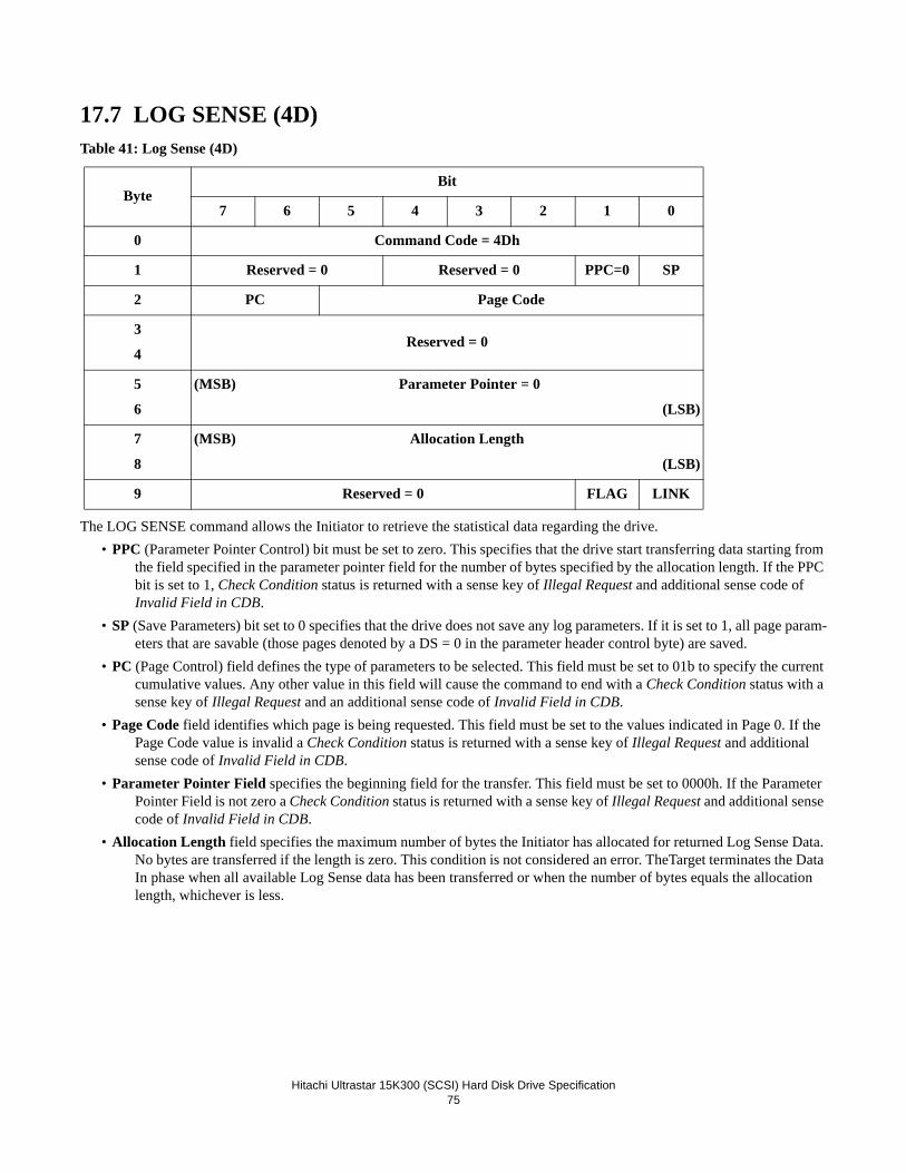
Hitachi Ultrastar 15K300 (SCSI) Hard Disk Drive Specification
75
17.7 LOG SENSE (4D)Table 41: Log Sense (4D)
The LOG SENSE command allows the Initiator to retrieve the statistical data regarding the drive.• PPC (Parameter Pointer Control) bit must be set to zero. This specifies that the drive start transferring data starting from
the field specified in the parameter pointer field for the number of bytes specified by the allocation length. If the PPC bit is set to 1, Check Condition status is returned with a sense key of Illegal Request and additional sense code of Invalid Field in CDB.
• SP (Save Parameters) bit set to 0 specifies that the drive does not save any log parameters. If it is set to 1, all page param-eters that are savable (those pages denoted by a DS = 0 in the parameter header control byte) are saved.
• PC (Page Control) field defines the type of parameters to be selected. This field must be set to 01b to specify the current cumulative values. Any other value in this field will cause the command to end with a Check Condition status with a sense key of Illegal Request and an additional sense code of Invalid Field in CDB.
• Page Code field identifies which page is being requested. This field must be set to the values indicated in Page 0. If the Page Code value is invalid a Check Condition status is returned with a sense key of Illegal Request and additional sense code of Invalid Field in CDB.
• Parameter Pointer Field specifies the beginning field for the transfer. This field must be set to 0000h. If the Parameter Pointer Field is not zero a Check Condition status is returned with a sense key of Illegal Request and additional sense code of Invalid Field in CDB.
• Allocation Length field specifies the maximum number of bytes the Initiator has allocated for returned Log Sense Data. No bytes are transferred if the length is zero. This condition is not considered an error. TheTarget terminates the Data In phase when all available Log Sense data has been transferred or when the number of bytes equals the allocation length, whichever is less.
ByteBit
7 6 5 4 3 2 1 0
0 Command Code = 4Dh
1 Reserved = 0 Reserved = 0 PPC=0 SP
2 PC Page Code
3
4Reserved = 0
5
6
(MSB) Parameter Pointer = 0
(LSB)
7
8
(MSB) Allocation Length
(LSB)
9 Reserved = 0 FLAG LINK

Hitachi Ultrastar 15K300 (SCSI) Hard Disk Drive Specification
76
17.7.1 Log Page parametersEach log page begins with a 4-byte page header followed by zero or more variable-length log parameters.
Page header Page Code field identifies which log page is being transferred.The Page Length field specifies the length in bytes of the following log parameters.
Log parameters Each log parameter begins with a 4-byte parameter header followed by one or more bytes of parameter value data.The Parameter Code field identifies which log parameter is being transferred for that log page.The Parameter Control field, the 3rd byte of each parameter header, contains several fields.
- DU The Disable Update bit is set to 0 to indicate that the drive updates the log parameter value to reflect events that should be noted by that parameter.
- TSD The Target Save Disable bit is set to zero to indicate that the drive provides a Target defined method for sav-ing log parameters.
- ETC The enable Threshold Comparison bit is set to 0 to indicate the drive does not perform comparisons between cumulative and any threshold values.
- TMC The Threshold Met Criteria field is not valid because this drive does not perform threshold comparisons. This field is set to 0.
- Format and Linking The F & L field indicates the type of log parameter and how parameters that reach their max-imum value are handled.
- 00b: Data counter: If any other parameter in this log page reaches its maximum value, then this parameter shall stop incrementing until reinitialized by a Log Select command.
- 01b: List format ASCII data: No maximum values to handle
- 10b: Data counter: If another parameter reported in this log page reaches its maximum value, then this param-eter shall not stop incrementing. This parameter may be reinitialized by a Log Select command.
- 11b: List format binary data: No maximum values to handle.

Hitachi Ultrastar 15K300 (SCSI) Hard Disk Drive Specification
77
17.7.2 Log Sense Page 0Page 0 indicates the supported log sense pages. This page is used to determine which additional pages an Initiator can request.
Table 42: Log Sense Page 0
ByteBit
7 6 5 4 3 2 1 0
0 Reserved Page code = 0
1 Reserved
2-3 Page Length = 000Dh(Number of Pages Supported)
4 First supported page 00h
5 Second supported page 02h
6 Third supported page 03h
7 Fourth supported page 05h
8 Fifth supported page 06h
9 Sixth supported page 0Dh
10 Seventh supported page 0Eh
11 Eighth supported page 0Fh
12 Ninth supported page 10h
13 Tenth supported page 15h
14 Eleventh supported page 2Fh
15 Twelfth supported Page Code =30h
16 Thirteenth supported Page Code = 37h

Hitachi Ultrastar 15K300 (SCSI) Hard Disk Drive Specification
78
17.7.3 Log Sense Page 2This page contains counters for write errors.
Table 43: Log Sense Page 2 (part 1 of 2)
Table 44: Log Sense Page 2 (part 2 of 2)
ByteBit
7 6 5 4 3 2 1 0
0 Reserved Page code = 02h
1 Reserved
2-3 PageLength = 54h
4-5 Parameter Code = 0000h
6 DU = 0 DS = 0 TSD = 0 ETC = 0 TMC = 0 F&L = 00b
7 Parameter Length = 08h
8-15 Errors recovered without delays
16-17 Parameter Code = 0001h
18 DU = 0 DS = 0 TSD = 0 ETC = 0 TMC = 0 F&L = 00b
19 Parameter Length = 08h
20-27 Errors recovered with possible delays
28-29 Parameter Code = 0002h
30 DU = 0 DS = 0 TSD = 0 ETC = 0 TMC = 0 F&L = 00b
31 Parameter Length = 08h
32-39 Reserved = 0
40-41 Parameter Code = 0003h
42 DU = 0 DS = 0 TSD = 0 ETC = 0 TMC = 0 F&L = 00b
43 Parameter Length = 08h
44-51 Total errors recovered
52-53 Parameter Code = 0004h
54 DU = 0 DS = 0 TSD = 0 ETC = 0 TMC = 0 F&L = 00b
55 Parameter Length = 08h
56-63 Times recovery invoked
ByteBit
7 6 5 4 3 2 1 0
64-65 Parameter Code = 0005h

Hitachi Ultrastar 15K300 (SCSI) Hard Disk Drive Specification
79
All parameter counts indicate the number of sectors with the specified types of errors, except Times Recovery Invoked, which is a cumulative count of all recovery steps attempted on all sectors written.
66 DU = 0 DS = 0 TSD = 0 ETC = 0 TMC = 0 F&L = 00b
67 Parameter Length = 08h
68-75 Total bytes written
76-77 Parameter Code = 0006h
78 DU = 0 DS = 0 TSD = 0 ETC = 0 TMC = 0 F&L = 00b
79 Parameter Length = 08h
80-87 Count of hard errors

Hitachi Ultrastar 15K300 (SCSI) Hard Disk Drive Specification
80
17.7.4 Log Sense Page 3This page contains counters for read errors. Table 45: Log Sense Page 3 (part 1 of 2)
Table 46: Log Sense Page 3 (part 2 of 2)
ByteBit
7 6 5 4 3 2 1 0
0 Reserved Page code = 03h
1 Reserved
2-3 PageLength = 54h
4-5 Parameter Code = 0000h
6 DU = 0 DS = 0 TSD=0 ETC = 0 TMC = 0 F&L = 00b
7 Parameter Length = 08h
8-15 Errors recovered without delay
16-17 Parameter Code = 0001h
18 DU = 0 DS = 0 TSD = 0 ETC = 0 TMC = 0 F&L = 00b
19 Parameter Length = 08h
20-27 Errors recovered with possible delays
28-29 Parameter Code = 0002h
30 DU = 0 DS = 0 TSD=0 ETC = 0 TMC = 0 F&L = 00b
31 Parameter Length = 08h
32-39 Reserved = 0
40-41 Parameter Code = 0003h
42 DU = 0 DS = 0 TSD=0 ETC = 0 TMC = 0 F&L = 00b
43 Parameter Length = 08h
44-51 Total errors recovered
52-53 Parameter Code = 0004h
54 DU = 0 DS = 0 TSD=0 ETC = 0 TMC = 0 F&L = 00b
55 Parameter Length = 08h
56-63 Times recovery invoked
64-65 Parameter Code = 0005h
ByteBit
7 6 5 4 3 2 1 0
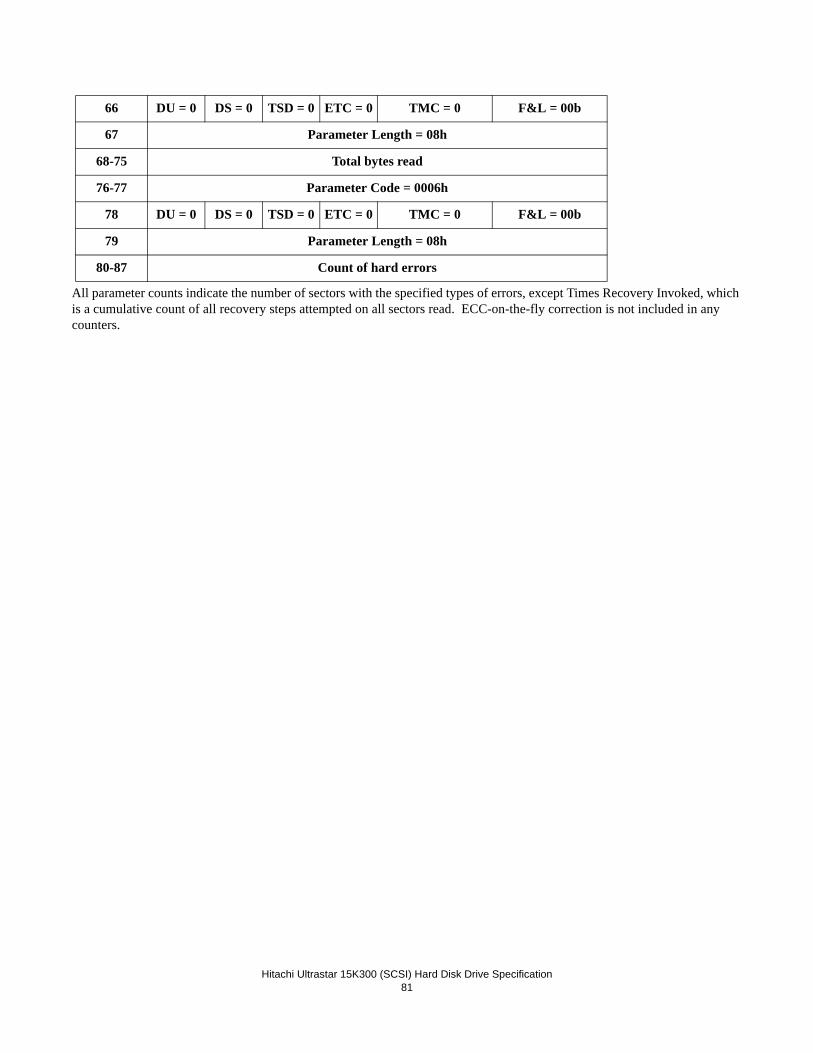
Hitachi Ultrastar 15K300 (SCSI) Hard Disk Drive Specification
81
All parameter counts indicate the number of sectors with the specified types of errors, except Times Recovery Invoked, which is a cumulative count of all recovery steps attempted on all sectors read. ECC-on-the-fly correction is not included in any counters.
66 DU = 0 DS = 0 TSD = 0 ETC = 0 TMC = 0 F&L = 00b
67 Parameter Length = 08h
68-75 Total bytes read
76-77 Parameter Code = 0006h
78 DU = 0 DS = 0 TSD = 0 ETC = 0 TMC = 0 F&L = 00b
79 Parameter Length = 08h
80-87 Count of hard errors

Hitachi Ultrastar 15K300 (SCSI) Hard Disk Drive Specification
82
17.7.5 Log Sense Page 5This page contains counters for verify errors.
Table 47: Log Sense Page 5 (part 1 of 2)
ByteBit
7 6 5 4 3 2 1 0
0 Reserved Page code = 05h
1 Reserved
2-3 PageLength = 54h
4-5 Parameter Code = 0000h
6 DU = 0 DS = 0 TSD = 0 ETC = 0 TMC = 0 F&L = 00b
7 Parameter Length = 08h
8-15 Errors recovered without delay
16-17 Parameter Code = 0001h
18 DU = 0 DS = 0 TSD = 0 ETC = 0 TMC = 0 F&L = 00b
19 Parameter Length = 08h
20-27 Errors recovered with possible delays
28-29 Parameter Code = 0002h
30 DU = 0 DS = 0 TSD = 0 ETC = 0 TMC = 0 F&L = 00b
31 Parameter Length = 08h
32-39 Reserved = 0
40-41 Parameter Code = 0003h
42 DU = 0 DS = 0 TSD = 0 ETC = 0 TMC = 0 F&L = 00b
43 Parameter Length = 08h
44-51 Total errors recovered
52-53 Parameter Code = 0004h
54 DU = 0 DS = 0 TSD = 0 ETC = 0 TMC = 0 F&L = 00b
55. Parameter Length = 08h
56-63 Times recovery invoked
64-65 Parameter Code = 0005h

Hitachi Ultrastar 15K300 (SCSI) Hard Disk Drive Specification
83
Table 48: Log Sense Page 5 (part 2 of 2)
All parameter counts indicate the number of sectors with the specified types of errors, except Times Recovery Invoked, which is a cumulative count of all recovery steps attempted on all sectors verified. ECC-on-the-fly correction is not included in any counters.
ByteBit
7 6 5 4 3 2 1 0
66 DU = 0 DS = 0 TSD = 0 ETC = 0 TMC = 0 F&L = 00b
67 Parameter Length = 08h
68-75 Total Bytes Verified
76-77 Parameter Code = 0006h
78 DU = 0 DS = 0 TSD = 0 TMC = 0 F&L = 00b
79 Parameter Length = 08h
80-87 Count of hard errors

Hitachi Ultrastar 15K300 (SCSI) Hard Disk Drive Specification
84
17.7.6 Log Sense Page 6This page contains counters for non-medium errors. This includes seek errors and other hardware type failures.
Table 49: Log Sense Page 6
ByteBit
7 6 5 4 3 2 1 0
0 Reserved Page code = 06h
1 Reserved
2-3 PageLength = 0Ch
4-5 Parameter Code = 00h
6 DU = 0 DS = 0 TSD = 0 ETC = 0 TMC = 0 F&L = 00b
7 Parameter Length = 08h
8-15 Error count
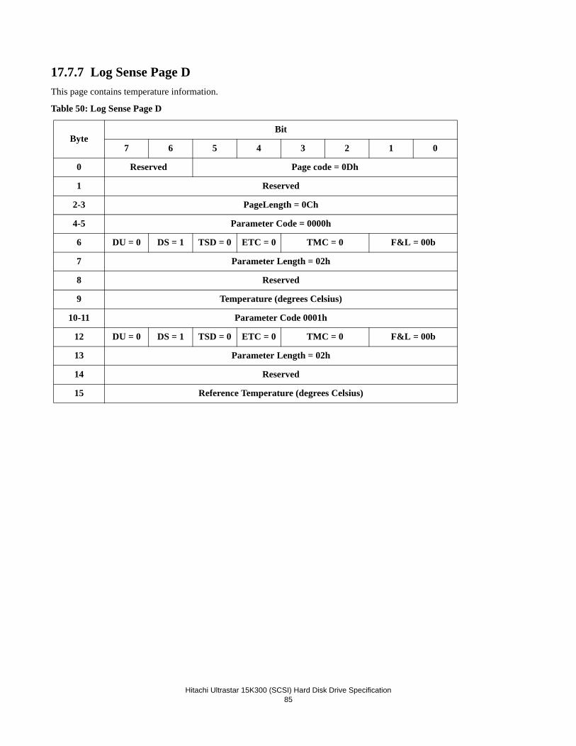
Hitachi Ultrastar 15K300 (SCSI) Hard Disk Drive Specification
85
17.7.7 Log Sense Page DThis page contains temperature information.
Table 50: Log Sense Page D
ByteBit
7 6 5 4 3 2 1 0
0 Reserved Page code = 0Dh
1 Reserved
2-3 PageLength = 0Ch
4-5 Parameter Code = 0000h
6 DU = 0 DS = 1 TSD = 0 ETC = 0 TMC = 0 F&L = 00b
7 Parameter Length = 02h
8 Reserved
9 Temperature (degrees Celsius)
10-11 Parameter Code 0001h
12 DU = 0 DS = 1 TSD = 0 ETC = 0 TMC = 0 F&L = 00b
13 Parameter Length = 02h
14 Reserved
15 Reference Temperature (degrees Celsius)

Hitachi Ultrastar 15K300 (SCSI) Hard Disk Drive Specification
86
17.7.8 Log Sense Page EThis page contains the start-stop cycle information.
Table 51: Log Sense Page E
The week and year that the device was manufactured shall be set in the parameter field defined by parameter code 0001h. The date of manufacture cannot be saved using the LOG SELECT command. The data is expected in numeric ASCII characters (30-39h) in the form YYYYWW. The accounting date specified by parameter code 0002h is a parameter that can be saved using the LOG SELECT command.
ByteBit
7 6 5 4 3 2 1 0
0 Reserved Page code = 0Eh
1 Reserved
2-3 PageLength = 24h
4-5 Parameter Code = 0001h
6 DU=0 DS=1 TSD=0 ETC=0 TMC = 0 F&L = 00b
7 Parameter Length = 06h
8-11 Year of Manufacture (4 ASCII characters)
12-13 Week of Manufacture (2 ASCII characters)
14-15 Parameter Code 0002h
16 DU=0 DS=0 TSD=0 ETC=0 TMC = 0 F&L = 00b
17 Parameter Length = 06h
18-21 Accounting Date Year (4 ASCII characters)
22-23 Accounting Date Week (2 ASCII characters)
24-25 Parameter Code 0003h
26 DU=0 DS=1 TSD=0 ETC=0 TMC = 0 F&L = 00b
27 Parameter Length = 04h
28-31 Specified cycle count over device lifetime
32-33 Parameter Code 0004h
34 DU=0 DS=1 TSD=0 ETC=0 TMC = 0 F&L = 00b
35 Parameter Length = 04h
36-39 Accumulated start-stop cycles (4 byte binary number)

Hitachi Ultrastar 15K300 (SCSI) Hard Disk Drive Specification
87
17.7.9 Log Sense Page FThis page contains the Application Client Log.
Table 52: Log Sense Page F
The following table describes the application client log parameter structure.
Table 53: Log Sense Page F, Application Client Log
Parameter code 0000h through 003Fh are supported.
The values stored in the parameter bytes represent data sent to the device in a previous LOG SELECT command.
ByteBit
7 6 5 4 3 2 1 0
0 Reserved Page code = 0Fh
1 Reserved
2-3 Page length = 4000h
Application client log parameter
4-259 1st application client log parameter
16132-16387 64th application client log parameter
ByteBit
7 6 5 4 3 2 1 0
0-1 Parameter code
2 DU= 1
DS= 0 TSD = 0 ETC = 0 TMC = 0 F&L = 00b
3 Parameter length = FCh
4- First parameter byte
255 Last parameter byte

Hitachi Ultrastar 15K300 (SCSI) Hard Disk Drive Specification
88
17.7.10 Log Sense Page 10This page contains self-test results. The results of the 20 most recent self-tests are stored in this Log page.
Table 54: Log Sense Page 10
The following table describes the self-test results log parameter structure
Table 55: Log Sense Page 10, self-test results
• Parameter Code identifies the log parameter for the log page. The parameter code field for the results of the most recent test will be 0001h. The parameter for the next most recent will be 0002h.
• Function Code contains the content of the Function Code field in the SEND DIAGNOSTIC command that initiated this self-test.
• Self-Test Results Value is described in the table below.
ByteBit
7 6 5 4 3 2 1 0
0 Reserved Page code = 10h
1 Reserved
2-3 PageLength = 190h
4-23 1st self-test results log parameter
384- 403 20th self-test results log parameter
ByteBit
7 6 5 4 3 2 1 0
0-1 Parameter code
2 DU = 0 DS = 0 TSD = 0 ETC = 0 TMC = 0 F&L = 11b
3 Parameter Length = 10h
4 Function Code RSVD Self-Test Results Value
5 Extended Segment Number
6-7 Timestamp
8-15 LBA of First Failure
16 Reserved Sense Key
17 Additional Sense Code
18 Additional Sense Code Qualifier
19 Vendor specific

Hitachi Ultrastar 15K300 (SCSI) Hard Disk Drive Specification
89
Table 56: Log Sense Page 10, self-test results
• Extended Segment Number This field identifies the number of the segment that failed during self-test. If no segment failed, this field will be 00h.
Value Description
0h The self-test routine completed without error.
1h The background self-test routine was aborted by the initiator using a SEND DIAGNOSTIC command with the Abort Background self-test function.
2h The self-test routine was aborted by the application client by a Task Manage-ment function or a reset.
3h An unknown error occurred while the Target was executing the self-test routine and the Target was unable to complete the self-test routine.
4h The self-test completed with a test element that failed and it is not known which test element failed.
5h The first segment of the self-test failed.
6h The second segment of the self-test failed.
7h The third or greater segment of the self-test failed (see the Extended segment number field).
8h-Eh Reserved.
Fh The self-test is in progress.

Hitachi Ultrastar 15K300 (SCSI) Hard Disk Drive Specification
90
Table 57: Log Sense Page 10, Extended Segment Number
• Timestamp This field contains the total accumulated power-on hours of the Target at the time the self-test completed.• LBA of first failure This field contains the LBA of the first logical block address where a self-test error occurred. If no
errors occurred during the self-test or the error is not related to a LBA then the field will be FFFFFFFFFFFFFFFFh.• Sense Key, Additional Sense Code and Additional Sense Code Qualifier These fields will contain the additional
information relating to the error or exception conditions during self-test.
See Section 19.40 “SEND DIAGNOSTIC (1D)” on page 262, for detailed listing of operations carried out by SEND DIAG-NOSTIC command and Power on Diagnostics.
ExtendedSegmentNumber
Short Self-Test Extended Self-Test
1h Drive Ready Test
2h Drive Diagnostics
3h SMART
4h Low Level Format check
5h Physical Head Check
6h Random Verify
7h- Verify First 300 MB
- Verify Last 100 MBVerify all LBAs
8h Recheck SMART

Hitachi Ultrastar 15K300 (SCSI) Hard Disk Drive Specification
91
17.7.11 Log Sense Page 15This page contains information about Background Medium Scan operations.
Table 58: Log Sense Page 15
The following table describes the BMS Status Parameter structure.
• Power On Minutes indicates the total power on minutes at the time the log page is requested• BMS Status is described in the following table
ByteBit
7 6 5 4 3 2 1 0
0 Reserved Page code = 15h
1 Reserved
2-3 Page Length = (19 + 24N -3)
Background Medium Scan parameters
4-19 BMS Status Parameter
20-43 First Medium Scan Parameter
...
19+24N Last Medium Scan Parameter
ByteBit
7 6 5 4 3 2 1 0
0-1 Parameter Code = 0000h
2 DU=0 DS=0 TSD=0 ETC=0 TMC=0 F&L = 11b
2-3 Page Length = 0Ch
4-7 Power On Minutes
8 Reserved = 0
9 BMS Status
10-11 Number of Scans Performed
12-13 Medium Scan Progress
14-15 Reserved = 0
BMS Status Description
00h No scans active
01h Background medium scan is active
03h-04h Not supported

Hitachi Ultrastar 15K300 (SCSI) Hard Disk Drive Specification
92
• Number of Scans Performed indicates the number of background scans that have been performed over the life of the-drive.
• Medium Scan Progress is a percent complete indication of the medium scan. The returned value is a numerator that has 65,536 (1 00 00h) as its denominator.
The following table describes the Medium Scan Parameter structure.
• Power On Minutes indicates the total power on minutes at the time the error was detected.• Reassign Status is set as shown below. Reassignment during the background scan is not supported.
05h Background scan halted due to medium formatted without P-List
06h Background scan halted due to a vendor-specific cause
07h Background scan halted due to temperature out of range
08h Scan suspended until BMS Interval Timer expires
09h - FFh Reserved
ByteBit
7 6 5 4 3 2 1 0
0-1 Parameter Code = 0001h - 0800h
2 DU=0 DS=0 TSD=0 ETC=0 TMC=0 F&L = 11b
2-3 Page Length = 14h
4-7 Power On Minutes
8 Reassign Status Sense Key
9 Additional Sense Code
10 Additional Sense Code Qualifier
11 Head (MSB) Cylinder
12-13
(MSB)
Cylinder
(LSB)
14-15
(MSB)
Sector
(LSB)
16-23 LBA
Reassign Status Description
0h No reassignment needed
1hReassignment pending receipt of Reassign command or write command (if auto write reallocation is allowed) from the initiator
BMS Status Description
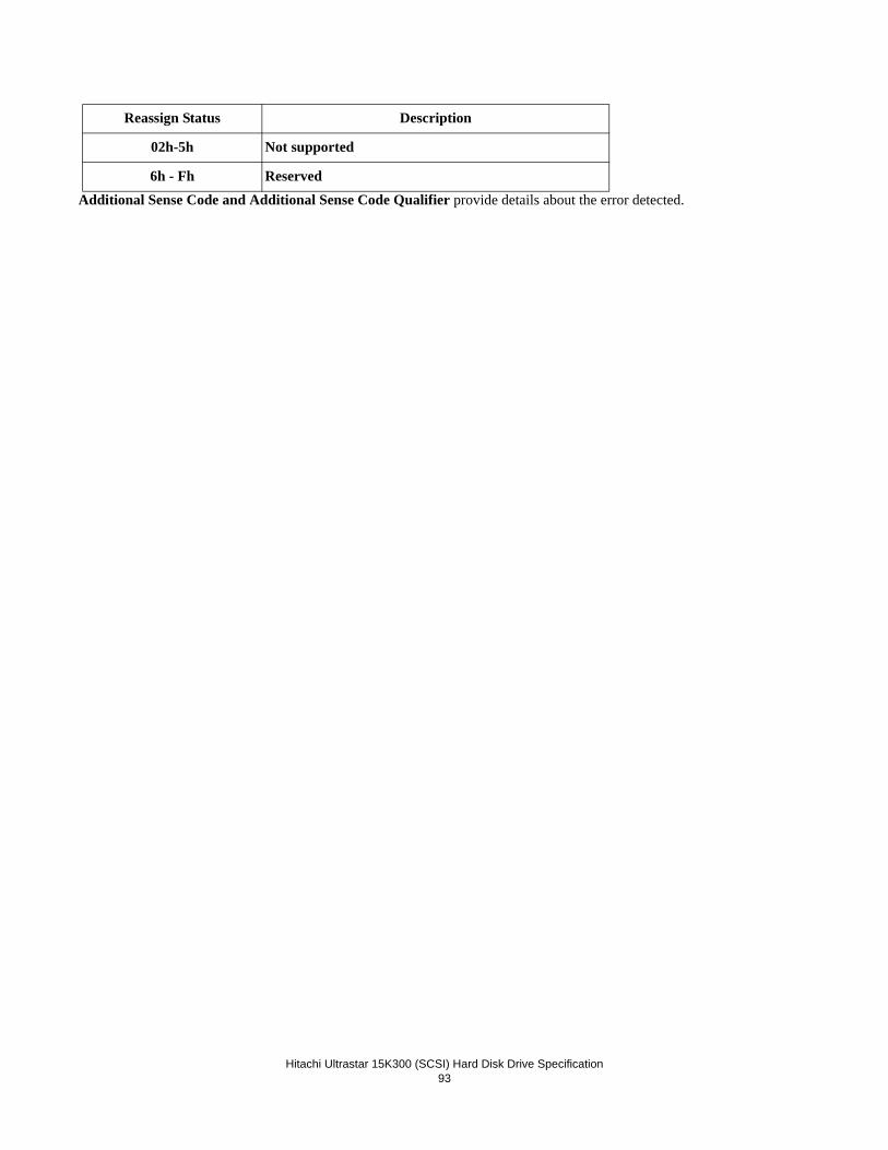
Hitachi Ultrastar 15K300 (SCSI) Hard Disk Drive Specification
93
Additional Sense Code and Additional Sense Code Qualifier provide details about the error detected.
02h-5h Not supported
6h - Fh Reserved
Reassign Status Description

Hitachi Ultrastar 15K300 (SCSI) Hard Disk Drive Specification
94
17.7.12 Log Sense Page 2FThis page contains SMART Status and Temperature Reading.
Table 59: Log Sense Page 2F
ByteBit
7 6 5 4 3 2 1 0
0 Reserved Page code = 2Fh
1 Reserved
2-3 PageLength = 8
4-5 Parameter Code = 0000h
6 DU = 0 DS = 0 TSD = 0 ETC = 0 TMC = 0 F&L = 11b
7 Parameter Length = 04h
8 SMART Sense Code Byte
9 SMART Sense Qualifier
10 Most Recent Temperature Reading
11 Vendor HDA Temperature Trip Point

Hitachi Ultrastar 15K300 (SCSI) Hard Disk Drive Specification
95
17.7.13 Log Sense Page 30This page contains Performance Counters.
Table 60: Log Sense Page 30
Page 30h returns performance counter information. This includes seek counters and buffer overrun/under run counters.
The appropriate seek counter is incremented once during execution of Pre-Fetch, Read, Verify, Write, Write and Verify, Write Same, and Seek commands.
Buffer Overrun conditions are detected during Read commands.
Buffer Underrun conditions are detected during Verify with ByteChk=1, Write, Write and Verify, and Write Same commands.
Only one seek counter is incremented for each of these commands and the counter is incremented only once per command. The length of the initial seek that is required to access the first Logical Block specified for the SCSI command determines which seek counter is incremented. The Zero Seek counter is incremented if a seek is not required or if only a head switch is
ByteBit
7 6 5 4 3 2 1 0
0 Reserved Page code = 30h
1 Reserved
2-3 Page Length = 0030h
4-5 Parameter Code = 0000h
6 DU = 0 DS = 0 TSD = 0 ETC = 0 TMC = 0 F&L = 00b
7 Parameter Length = 2Ch
8-9 Zero Seeks
10-11 Seeks > = to 2/3
12-13 Seeks > = 1/3 and < 2/3
14-15 Seeks > = 1/6 and < 1/3
16-17 Seeks > = 1/12 and < 1/6
18-19 Seeks > 0 and < 1/12
20-23 Reserved = 0
24-25 Overrun Counter
26-27 Under run Counter
28-31 Device Cache Full Read Hits
32-35 Device Cache Partial Read Hits
36-39 Device Cache Write Hits
40-43 Device Cache Fast Writes
44-47 Device Cache Read Misses
48-51 Reserved = 0

Hitachi Ultrastar 15K300 (SCSI) Hard Disk Drive Specification
96
required to access the first Logical Block. After the initial seek, no further counter incrementing is performed for that com-mand.
Note: The length of a seek as reported in page 30 may differ from expected results. The reason for this is that the drive exe-cutes Idle Time Functions between operations of the drive. The seek operations that occur in Idle Time Functions are not directly entered into page 30 seek counters but they change the length of the following seek. This is because after the Idle Time Function is completed, the heads will not necessarily be in the same position as they were at the completion of the previous command.
A buffer overrun or under run condition occurs when the Initiator does not transfer data to or from the Target data buffer fast enough to keep up with reading or writing the media. The buffer overrun counter is incremented during operations that require a Data In phase when a buffer full condition prevents the continued transfer of data from the media to the data buffer. The buffer under run counter is incremented during operations that require a Data Out phase when a buffer empty condition pre-vents the start or continuation of a data transfer from the data buffer to the media (or a data transfer from the media for a Verify command with BytChk=1).
Buffer Overrun conditions are detected during the following SCSI commands:• READ (6)• READ (10)
Buffer Under Run conditions are detected during the following SCSI commands:• VERIFY WITH BytChk=1• VERIFY (16) WITH BytChk=1• WRITE (6)• WRITE (10)• WRITE AND VERIFY• WRITE AND VERIFY (16)• WRITE SAME• WRITE SAME (16)• ZERO SEEKS
The number of times no seek was required. The operation may have resulted in a head switch.
• SEEKS >= 2/3 DISK The number of seeks equal to or greater than 2/3 of the disk.
• SEEKS >= 1/3 AND < 2/3 DISK The number of seeks equal to or greater than 1/3 and less than 2/3 of the disk.
• SEEKS >= 1/6 AND < 1/3 DISK The number of seeks equal to or greater than 1/6 and less than 1/3 of the disk.
• SEEKS >= 1/12 AND < 1/6 DISK The number of seeks equal to or greater than 1/12 and less than 1/6 of the disk.
• SEEKS > 0 AND < 1/12 DISK The number of seeks less than 1/12 of the disk.
• OVERRUN COUNTERThe number of times that data was available to be transferred from the media but the device buffer still contained data that had not been retrieved by the Initiator. Consequently, the disk had to take additional revolutions until the buffer was available to accept data.
• UNDER RUN COUNTER

Hitachi Ultrastar 15K300 (SCSI) Hard Disk Drive Specification
97
The number of times that the drive was ready to transfer data to its disk (on a write), but its buffer was empty (i.e., had not been filled by the Initiator), thus the disk was forced to take extra revolutions.
• DEVICE CACHE FULL READ HITSThe number of times that all of the data requested by the read operation was obtained from the device read or write cache.
• DEVICE CACHE PARTIAL READ HITSThe number of times that a portion, but not all, of the data requested by the read operation was obtained from the device read or write cache. A physical operation to the device media was required to obtain the remaining data.
• DEVICE CACHE WRITE HITSThe number of times that the data associated with a write operation replaces, or is combined with, existing data in the device write cache, thereby eliminating a write operation.
• DEVICE CACHE FAST WRITESThe number of times that space was available in the device write cache for the data associated with a write operation and a response was returned immediately.
• DEVICE CACHE READ MISSES
The number of times that none of the data requested by the read operation was obtained from the read cache.
The statistics reported by this page are lost on a self-initiated reset or when the Drive is powered off. Even though the DS field equals zero, the parameters on this page are not savable.

Hitachi Ultrastar 15K300 (SCSI) Hard Disk Drive Specification
98
17.7.14 Log Sense Page 37This page contains a series of miscellaneous data counters including information about predictive failure analysis occurrences.
Table 61: Log Sense Page 37
The Power on Hours field specifies the total time the drive has been powered on in hours only.
The Max. Drive Temperature field specifies the maximum temperature, in degrees Celsius, the drive has ever reached.
The Glist Size field gives the total number of LBAs that have been reassigned on the drive.
The Number of PFA Occurrences field gives the number of PFA occurrences during the life of the drive and not the number of PFA events that have been reported. The number of reported PFA events may be less due to the settings of Mode Page 0x1C.
If set, the Media and Hardware PFA bits indicate that a PFA trip has occurred during the life of the drive. These flags are set during a PFA occurrence that may or may not coincide with the reporting of a PFA event as mentioned above.
Total Read Commands counter is incremented for each Read (6) and Read (10) command received.
Total Write Commands counter is incremented for each Write (6), Write (10), Write Verify and Write Verify (16) command received.
Flash Correction Count is incremented each time ECC correction is applied to data stored in Flash ROM.
ByteBit
7 6 5 4 3 2 1 00 Reserved Page code = 37h1 Reserved
2-3 Page Length = 0030h (48)4-5 Parameter Code = 0000h6 DU=0 DS=0 TSD=0 ETC=0 TMC = 0 F&L = 00b7 Parameter Length = 2Ch8
-
11
(MSB)
Power on Hours (hours only)
(LSB)12
-
19
(MSB)
Total Bytes Read
(LSB)20
-
27
(MSB)
Total Bytes Written
(LSB)28 Max Drive Temp (degrees Celsius)
29 - 30(MSB) GList Size
(LSB)31 Number of PFA Occurrences
32 MED PFA
HDW PFA Reserved = 0
33 - 40 Total Read Commands41 - 48 Total Write Commands
49 Reserved = 050-51 Flash Correction Count

Hitachi Ultrastar 15K300 (SCSI) Hard Disk Drive Specification
99

Hitachi Ultrastar 15K300 (SCSI) Hard Disk Drive Specification
100
17.8 MODE SELECT (15)Table 62: Mode Select (15)
The MODE SELECT (15) command provides a means for the Initiator to specify LUN or device parameters to the Target. It also allows an Initiator to specify options the Target uses in error recovery, caching, and formatting.
There is a single set of Mode Page parameters shared by all Initiators.• PF A PF (Page Format) bit value of one indicates that the data sent by the Initiator after the Mode Select Header and the
Block Descriptor, if any, complies to the Page Format. The Target ignores this field since it only accepts mode param-eters in the Page Format.
• SP Save Pages. This indicates
0 The drive shall not save the pages sent during the Data Out phase but will use them for all following commands until the power is removed, a reset is received, or a new MODE SELECT command is received.
1 The drive will save the data in the reserved area of the disk. It will be used for all the following commands until another MODE SELECT command is issued. This information is maintained over a power cycle or reset of the drive.
• Parameter List Length This specifies the number of bytes to be sent from the Initiator. A parameter list length of zero suppresses data transfer and is not considered an error.
The MODE SELECT parameter list contains a 4-byte header followed by zero or one block descriptor followed by zero or more pages. The pages that are valid with this command are defined in the addendum under the heading Mode Select Data, as they vary with the drive model.
Application Note
The Initiator should issue a MODE SENSE command requesting all Changeable values (see PCF field in byte two of the CDB in) prior to issuing a MODE SELECT command. This is necessary to find out which pages are implemented by the drive and the length of those pages. In the Pages of the MODE SENSE command the drive will return the number of bytes supported for each Page. The Page Length set by the Initiator in the MODE SELECT command must be the same value as returned by the drive in MODE SENSE Page Length. If not, the drive will return Check Condition status with sense key of Illegal Request.
Note: If an Initiator sends a MODE SELECT command that changes any parameters that apply to other Initiators, the drive shall generate an unit attention condition for all Initiators except for the one that issued the MODE SELECT command. The drive shall set the additional sense code to Parameters Changed (2Ah).
ByteBit
7 6 5 4 3 2 1 0
0 Command Code = 15h
1 Reserved = 0 PF=1 Reserved = 0 SP
2
3Reserved = 0
4 Parameter List Length
5 VU = 0 Reserved = 0 FLAG LINK

Hitachi Ultrastar 15K300 (SCSI) Hard Disk Drive Specification
101
17.9 MODE SELECT (55)Table 63: Mode Select (55)
The MODE SELECT (55) command provides a means for the Initiator to specify LUN or device parameters to the Target. See the MODE SELECT (15) command for a description of the fields in this command.
ByteBit
7 6 5 4 3 2 1 0
0 Command Code = 55h
1 Reserved = 0 PF=1 Reserved = 0 SP
2-6 Reserved = 0
7-8(MSB) Parameter List Length
(LSB)
9 VU = 0 Reserved = 0 FLAG LINK

Hitachi Ultrastar 15K300 (SCSI) Hard Disk Drive Specification
102
17.10 MODE SENSE (1A)Table 64: Mode Sense (1A)
The MODE SENSE (1A) command provides a means for the drive to report various device parameters to the Initiator. It is the complement to the MODE SELECT command.
If the DBD (Disable Block Descriptor) bit is zero, the Target will return the Block Descriptor. If the DBD bit is set to 1, the Target will not return the Block Descriptor.
Allocation Length indicates the maximum number of bytes that the Initiator has set aside for the DATA IN phase. A value of zero is not considered an error. If the allocation length is smaller than the amount available, that portion of the data up to the allocation length will be sent. This may result in only a portion of a multi-byte field being sent.
Page Control Field: PCF (Page Control Field) defines the type of Page Parameter values to be returned.
PCF Meaning
0 0 Report current values. The drive returns the current values under which the logical unit is presently configured for the page code specified. The current values returned are
1. Initially following power-up but before the media is accessed, the default values become current. Once the media can be accessed, the saved values are read from the Reserved Area and become current.
2.The parameters set in the last successful MODE SELECT command.3.The saved values if a MODE SELECT command has not been executed since the last power-on, hard RESET con-
dition, or TARGET RESET message.Following the completion of start-up, execution of the MODE SELECT command can modify the current values.Note: Those parameters associated with format are not considered current and are not saved until the successful com-pletion of a FORMAT UNIT command.In addition, the current values take on the saved values after a reset if the parameters were saved. If the Page Code is 3Fh, then all pages implemented by the Target are returned to the Initiator with fields and bit values set to current val-ues.If the Page Code is not 3Fh, the page defined by the Page Code, if supported by the Target, is returned with fields and bits set to current values.Note: The drive will not process the MODE SELECT command until the completion of spin-up. Therefore, the Initi-ator cannot modify the current values prior to the saved values being read in.
0 1 Report changeable value. The drive returns the changeable values for the page code specified. The page requested is returned containing information that indicates which fields are changeable. All bits of parameters that are changeable shall be set to one. Parameters that are defined by the drive shall be set to zero. If any part of a field is changeable, all bits in that field shall be set to one. Note: For a value field such as the buffer ratios of page 2 the bit field will not indicate the range of supported values but rather that the field is supported.
ByteBit
7 6 5 4 3 2 1 0
0 Command Code = 1Ah
1 Reserved RSVD DBD Reserved = 0
2 PCF Page Code
3 Subpage Code
4 Allocation Length
5 VU = 0 Reserved = 0 FLAG LINK

Hitachi Ultrastar 15K300 (SCSI) Hard Disk Drive Specification
103
1 0 Report default value. The drive returns the default values for the page code specified. The parameters not supported by the drive are set to zero.
1 1 Report saved value. The drive returns the saved value for the page code specified.
Saved values are one of the following:
- the values saved as a result of MODE SELECT command
- identical to the default values
- zero when the parameters are not supportedThe Page Length byte value of each page returned by the drive indicates up to which fields are supported on that page.
Page Code: This field specifies which page or pages to return. Page code usage is defined in the figure below.
Table 65: Page Code Usage
If a Page Code of 3Fh is used, MODE SENSE returns the pages in ascending order with one exception. Page 0 is always returned last in response to a MODE SENSE command.
If an unsupported page is selected, the command is terminated with a CHECKT CONDITION status and available sense of ILLEGAL REQUEST/INVALID FIELD IN CDB.
Subpage Code: This field specifies the subpage to return, and may be set to a specific page, or to FFh for all supported sub-pages.
17.10.1 Mode Parameter ListThe mode parameter list contains a header followed by zero or more block descriptors followed by zero or more variable length pages.
17.10.1.1 HeaderThe 6-byte command descriptor block header is defined below.
Table 66: Mode parameter header (6)
The 10-byte CDB header is defined below.
Page Code Description
00h - 1Ch
3Fh
Return specific page, if supported.
Return all supported pages.
ByteBit
7 6 5 4 3 2 1 0
0 Mode Data Length
1 Medium Type = 0
2 WP=0 Reserved=0 DPOFUA=1 Reserved = 0
3 Block Descriptor Length (= 0 or 8)
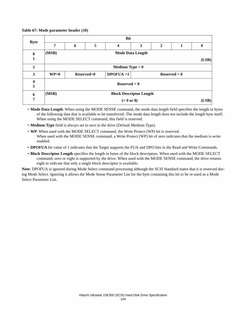
Hitachi Ultrastar 15K300 (SCSI) Hard Disk Drive Specification
104
Table 67: Mode parameter header (10)
• Mode Data Length. When using the MODE SENSE command, the mode data length field specifies the length in bytes of the following data that is available to be transferred. The mode data length does not include the length byte itself. When using the MODE SELECT command, this field is reserved.
• Medium Type field is always set to zero in the drive (Default Medium Type).• WP. When used with the MODE SELECT command, the Write Protect (WP) bit is reserved.
When used with the MODE SENSE command, a Write Protect (WP) bit of zero indicates that the medium is write enabled.
• DPOFUA bit value of 1 indicates that the Target supports the FUA and DPO bits in the Read and Write Commands.• Block Descriptor Length specifies the length in bytes of the block descriptors. When used with the MODE SELECT
command, zero or eight is supported by the drive. When used with the MODE SENSE command, the drive returns eight to indicate that only a single block descriptor is available.
Note: DPOFUA is ignored during Mode Select command processing although the SCSI Standard states that it is reserved dur-ing Mode Select. Ignoring it allows the Mode Sense Parameter List for the byte containing this bit to be re-used as a Mode Select Parameter List.
ByteBit
7 6 5 4 3 2 1 0
01
(MSB) Mode Data Length
(LSB)
2 Medium Type = 0
3 WP=0 Reserved=0 DPOFUA =1 Reserved = 0
45 Reserved = 0
67
(MSB) Block Descriptor Length
(= 0 or 8) (LSB)

Hitachi Ultrastar 15K300 (SCSI) Hard Disk Drive Specification
105
17.10.1.2 Block DescriptorTable 68: Mode Parameter Block Descriptor
The Block descriptor provides formatting information about the Number of Blocks (user addressable) to format at the speci-fied Block Length.
• Number of BlocksWhen used with the MODE SELECT command, the Number of Blocks field must be
- Zero to indicate not to change available blocks
- 0xFFFFFFFF to indicate all available blocks
- The exact number of blocks in the data area of the drive, which can be obtained with the MODE SENSE
- The number of blocks less than exact one, in order to CLIP the number of blocksAny other value is invalid and causes the command to fail with Check Condition status.When used with the MODE SENSE command, the field contains the exact number of blocks.
• Density Code- Always 0 for direct access devices.
• Block LengthThe Block Length field reflects the number of bytes of user data per sector (not including any protection informa-tion). When used with the MODE SELECT command, the Block length field must contain the value from 512 to 528 (8 bytes step) or zero. Otherwise the drive will terminate the command with Check Condition status.
A FORMAT UNIT command is required to cause these parameters to become current only if the block length param-eter is different from the current block length.
When used with the MODE SENSE command, the field is dependent on how the media is currently formatted.
Byte 0
Byte 1
Byte 2
Byte 3
(MSB)
Number of Blocks
(LSB)
Byte 4 Density code = 0
Byte 5
Byte 6
Byte 7
(MSB)
Block Length
(LSB)

Hitachi Ultrastar 15K300 (SCSI) Hard Disk Drive Specification
106
17.10.1.3 Page DescriptorTable 69: Mode Parameter Page Format
Each mode page contains a page code, a page length, and a set of mode parameters.
When using the MODE SENSE command, a Parameter Savable (PS) bit of one indicates that the mode page can be saved by the drive in the reserved area of the drive. A PS bit of zero indicates that the supported parameters cannot be saved. When using the MODE SELECT command, the PS bit is reserved (zero).
SPF (Sub-Page Format) is set to zero to indicate the short page format is used. The bit is set to one to indicate the long format is used, supporting sub-pages. The drive supports the following mode page codes:
Table 70: Mode Parameter Page Format
The page length field specifies the length in bytes of the mode parameters that follow. If the Initiator does not set this value to the value that is returned for the page by the MODE SENSE command, the drive will terminate the command with Check Con-dition status.
Byte 0 PS SPF Page Code
Byte 1 Page Length
Byte 2-n Mode Parameters
Page Description PS
00 Vendor Unique Parameters 1
01 Read-Write Error Recovery Parameters 1
02 Disconnect/Reconnect Control Parameters 1
03 Format Device Parameters 0
04 Rigid Disk Geometry Parameters 0
07 Verify Error Recovery Parameters 1
08 Caching Parameters 1
0A Control Mode Page 1
0C Notch Parameters 1
19 Port Control Page 1
1A Power Control Parameters 1
1C Informational Exceptions Control 1

Hitachi Ultrastar 15K300 (SCSI) Hard Disk Drive Specification
107
17.10.2 Mode Page 00 (Vendor Unique Parameters)Table 71: Vendor Unique Parameters - Page00
• UAI (Unit Attention Inhibit) bit is not used during normal operation when the UAI jumper is removed from the drive. It may however be changed by the user with no effects. If the UAI jumper is added to the drive, then this bit controls the generation of unit attention conditions.
• MRG (Merge Glist into Plist) bit is set to 1 for merging the Glist entries into the Plist during FORMAT UNIT command.• ASDPE (Additional Save Data Pointer Enable) bit is used to control the sending of additional save data pointers mes-
sages. When set it will cause a save data pointers message to be sent on every disconnection. This bit is only used by the Target after the Default Mode parameter values are overridden with the Saved values that are read from the Reserved Area of the media as a part of the motor startup sequence. Before the Saved values are read from the Reserved Area of the media, the Save Data Pointer message is always sent to the Initiator prior to disconnection. When not set, a save data pointers message is sent only if the current connection contained a data phase and a further data phase will be required to complete the command.
• VGMDE (Veggie Mode) bit set to 1 will cause the drive to execute random self-seeks. To enable this mode, the initiator must perform the mode select to set the bit while the drive is spinning, then Stop Unit, then Start Unit. VGMDE set to 0 disables the self-seeks (normal operation).
• CMDAC (Command Active) bit in conjunction with LED Mode bits determines if an LED on the drive is activated while commands are active. If CMDAC bit is one and LED Mode bits are zero, an LED driver is active when a com-mand is queued or executed.
ByteBit Default
7 6 5 4 3 2 1 0
0 PS 0 Page Code = 00h 80h
1 Page Length = 0Eh 0Eh
2 Ignored UAI MRG Ignored 10h
3 ASDPE VGMDE CMDAC Ignored RRNDE Ignored 20h
4 Ignored 00h
5 Ignored FDD DPSDP Ignored CAEN Ignored 02h
6 IGRA AVERP Ignored OCT (high nibble) 00h
7 Overall Command Timer (low byte) 00h
8 Ignored LED Mode 00h
9 Temperature Threshold 00h
10 Command Aging Limit (Hi byte) 00h
11 Command Aging Limit (Low byte) 30h
12 Read Reporting Threshold 0Ah
13 Write Reporting Threshold 0Ah
14 DRRT Ignored FFMT Ignored 00h
15 Ignored FCERT Ignored Reserved = 0 00h

Hitachi Ultrastar 15K300 (SCSI) Hard Disk Drive Specification
108
• RRNDE (Report Recovered Non Data Errors) bit controls the reporting of recovered Non Data Errors when the PER bit is set. If RRNDE is set, recovered Non Data Errors are reported. If the RRNDE bit is not set, then recovered Non Data Errors are not reported.
• FDD (Format Degraded Disable) controls the reporting of Format Degraded sense data for Test Unit Ready commands when the drive is in a format degraded state. When the FDD bit is one, Format Degraded sense data will not be reported for a Test Unit Ready command. When the FDD bit is zero, Format Degraded sense data will be reported for Test Unit Ready commands when the drive is in a format degraded state. This bit does not affect the reporting of Format Degraded conditions for any media access commands.
• DPSDP The Data Phase Save Data Pointer bit controls whether the Drive sends a Save Data Pointer message at the end of the data phase. A DPSDP bit of 0 indicates that the Drive sends a Save Data Pointer message prior to disconnec-tion only if the following conditions are true:
- A data phase has occurred since the connection for the current command was established.
- Another data phase is required to successfully complete the command.
A DPSDP bit of 1 indicates that the Drive will send a Save Data Pointer message prior to every disconnection once a data phase has occurred for the current command. If the ASDPE bit is set to 1, the Save Data Pointer message is sent prior to every disconnect regardless of the value of the DPSDP bit.
• CAEN (Command Aging Enable) When set this bit causes the Command Age Limit timer to be used to avoid commands waiting in the command queue for an indefinite period. When commands have been in the queue for a period of time greater than the timer limit they will be reordered to be executed on a first come first served basis. When this bit is reset, commands are always executed based on the queue reordering rules.
• IGRA (Ignore Reassigned LBA) bit works in conjunction with the RC bit (Mode Page 01h, byte 2, bit 4). The main pur-pose of this bit is to avoid undesirable read processing time delays due to reassigned LBA processing for continuous data availability requirements such as Audio Visual applications. If IGRA is set to one and RC is set to one, out-of-line reassigned LBAs will not be processed. If IGRA is set to one and RC is set to zero, or if IGRA is set to zero, reassigned LBAs will be processed normally.
• AVERP (AV ERP Mode) bit is set to one in order to specify maximum retry counts during Read DRP. When AVERPbit is set to one, the maximum retry counts for read operations is specified by Read Retry Count (Mode Page 1 Byte 3). AVERP bit is set to zero to specify that the drive shall process read DRP up to the default maximum retry count when Read Retry Count is set to a non-zero value.
• OCT (Overall Command Timer) controls the maximum command execution time, from receipt by the drive until status is returned. If the command is unable to complete in the specified amount of time, it will be aborted with Check Con-dition status, Aborted Command sense key. The Overall Command Timer does not alter the behavior of the Com-mand Aging Limit or Recovery Time Limit. Each unit of this timer is 50 milliseconds. Setting the value to zero disabled the feature.
• LED Mode is designed to control the operation of a drive LED driver.
- LED Mode = 0000b
The CMDAC bit controls the LED.
CMDAC = 1 (Command Active)
CMDAC = 0 (Motor Active)
- LED Mode = 0001b (Motor Active)
When the motor is spinning, the LED is high.
- LED Mode = 0010b (Command Active).
When there is a command active or in the queue, the LED is high.• Temperature Threshold specifies the threshold value in degrees Celsius for the thermal sensor warning message. A
value of 0 selects the default value (85 degrees Celsius).

Hitachi Ultrastar 15K300 (SCSI) Hard Disk Drive Specification
109
• Command Aging Limit This value controls the maximum time a command should wait in the command queue when the CAEN bit is set. Each unit of this timer is 50 ms.
• Read Reporting Threshold specifies the error reporting threshold for recovered data errors during read operations when PER=1.
• Write Reporting Threshold specifies the error reporting threshold for recovered data errors during write operations when PER=1.
• DRRT (Disable Restore Reassign Target) bit disables the reading and restoration of the target LBA during a Reassign Blocks command. If the DRRT bit is zero, the reassign command attempts to restore the target LBA's data. If the data cannot be restored, the target LBA is reassigned and written with a data pattern of all 00s. If the DRRT bit is one, no attempt is made to restore the target LBA.
• FFMT (Fast Format Enable) bit allows the formatting of the drive without any writes to the customer media. All format operations are allowed including changing block sizes and manipulating defects. The drive will operate normally after a fast format with the following caveat: since no data is written to any customer data blocks as a result of a Fast Format operation, there is a possibility that a read attempt to any particular block (without having previously written to that block) will result in an unrecoverable data error. This will most likely happen if the block size is changed as every LBA will contain data of an incorrect length and apparently an incorrect starting point. It is also possible to generate an uncorrectable data error without changing block sizes if the defect list is shortened and previously bad blocks become visible in the customer address space. Of course ALL DATA ON THE DRIVE WILL BE LOST as the result of any format operation and so any attempt to read blocks which have not been written to will result in unpredictable behavior.
• FCERT (Format Certification) bit determines whether the certification step will be performed during a Format Unit command. FCERT bit set to 0 disables certification. FCERT bit set to 1 enables the certification step.

Hitachi Ultrastar 15K300 (SCSI) Hard Disk Drive Specification
110
17.10.3 Mode Page 01 (Read/Write Error Recovery Parameters)Table 72: Mode Page 01 (Vendor Unique Parameters)
The Read-Write recovery parameters that will be used during any command that performs a read or write operation to the medium are as follows:
• AWRE Automatic Write Reallocation Enabled bit, set to zero indicates that the drive shall not perform automatic reallo-cation of defective data blocks during write operations. An AWRE bit set to one indicates that the drive shall perform automatic reallocation of defective data blocks during write operations.
• ARRE Automatic Read Reallocation Enabled bit, set to zero indicates that the drive shall not perform automatic reallo-cation of defective data blocks during read operations. ARRE bit set to one indicates that the drive shall perform automatic reallocation of defective data blocks during read operations.
• TB Transfer Block bit, set to one indicates that a data block that is not recovered within the recovery limits specified shall be transferred to the Initiator before Check Condition status is returned. A TB bit set to zero indicates that such a data block shall not be transferred to the Initiator. Data blocks that can be recovered within the recovery limits are always transferred regardless of the value of the bit.
• RC Read Continuous bit, set to one requests the Target to transfer the entire requested length of data without adding delays that would increase or ensure data integrity. This implies that the Target may send erroneous data. This bit has priority over all other error control bits (PER, DTE, DCR, TB). RC set to zero indicates normal interpretation of PER, DTE, DCR, and TB values. The RC bit setting is used by the Target when reporting errors associated with the transfer of the Initiator's data for the Read commands interpretation of PER, DTE, DCR, and TB values. The RC bit applies only to READ commands.
Note: The Target implementation of the RC option is to disable error detection of the data fields but continue normal error detection and recovery for errors occurring in the servo field. If a servo field failure occurs, normal DRP could result in considerable recovery action, including proceeding through all levels of DRP.
• EER an Enable Early Recovery bit, must be set to zero, indicating that the drive shall use an error recovery procedure that minimizes the risk of misdetection or miscorrection during the data transfer. Data shall not be fabricated.
ByteBit
7 6 5 4 3 2 1 0 Default
0 PS 0 Page Code = 01h 81h
1 Page Length = 0Ah 0Ah
2 AWRE ARRE TB RC EER=0 PER DTE DCR C0h
3 Read Retry Count 01h
4 Obsolete = 0 00h
5 Obsolete = 0 00h
6 Obsolete = 0 00h
7 Reserved 00h
8 Write Retry Count 01h
9 Reserved 00h
10
11
(MSB) Recovery Time Limit
(LSB)
00h

Hitachi Ultrastar 15K300 (SCSI) Hard Disk Drive Specification
111
• PER a Post Error bit, is set to one to indicate that the drive reports recovered errors.• DTE (Data Terminate on Error) bit set to one specifies that data transfer will be halted when the first recovered error is
encountered. PER must be set to one when DTE is set to one. DTE set to zero will cause data transfer to continue when recovered errors are encountered.
• DCR a Disable Correction bit, is set to one to indicate that Error Correction Code is not used for data error recovery. A DCR bit of zero indicates that ECC is applied to recover the data.
• Read Retry Count sets a limit on the amount of DRP passes in which the Target attempts to recover read errors. A value of zero disables all data recovery procedures. When AVERP bit (Mode Page 0 Byte 6 Bit 6) is zero, a value of non-zero in Read Retry Count enables all steps of DRP. When AVERP bit is one, the number in Read Retry Count sets the maximum retry count of DRP.
• Write Retry Count sets a limit on the amount of DRP passes in which the Target attempts to recover write errors. A value of zero disables all data recovery procedures..
• Recovery Time Limit indicates the period in 1 millisecond increments for the maximum recovery time of a single LBA. The value must be from 40 ms to 65535 ms (65.5 seconds). The granularity of the timer is 50 ms. If an LBA is not able to be recovered within the limit, a Check Condition will be returned. The Recovery Time Limit will not be applied yo Writes when WCE=1. A value of zero disables the timer.

Hitachi Ultrastar 15K300 (SCSI) Hard Disk Drive Specification
112
The following summarizes valid modes of operation. If an illegal mode is set, the MODE SELECT command will complete successfully but the action of the drive when an error occurs is undefined.
PER DTE DCR TB DESCRIPTION 0 0 0 0 Retries and Error Correction are attempted. Recovered or corrected data (if any) or both are transferred
with no Check Condition status at the end of the transfer.no err The transfer length is exhausted.soft err The transfer length is exhausted. Transferred data includes blocks containing recovered errors.hard err Data transfer stops when an unrecoverable error is encountered. The unrecoverable block is not
transferred to the Initiator. The drive then creates the Check Condition status with the appropri-ate sense key.
0 0 0 1 Retries and Error Correction are attempted. Recovered or corrected data (if any) or both are transferred with no Check Condition status at the end of the transfer.no err The transfer length is exhausted.soft err The transfer length is exhausted. Transferred data includes blocks containing recovered errors.hard err Data transfer stops when an unrecoverable error is encountered. The unrecoverable block is
transferred to the Initiator. The drive then creates the Check Condition status with the appropri-ate sense key.
0 0 1 0 Retries are attempted but no error correction (ECC) is applied. Recovered data (if any) are transferred with no Check Condition status at the end of the transfer.no err The transfer length is exhausted.soft err The transfer length is exhausted. Transferred data includes blocks containing recovered errors.hard err Data transfer stops when an unrecoverable error is encountered. The unrecoverable block is not
transferred to the Initiator. The drive then creates the Check Condition status with the appropri-ate sense key.
0 0 1 1 Retries are attempted but no error correction (ECC) is applied. Recovered data (if any) are transferred with no Check Condition status at the end of the transfer.no err The transfer length is exhausted.soft err The transfer length is exhausted. Transferred data includes blocks containing recovered errors.hard err Data transfer stops when an unrecoverable error is encountered. The unrecoverable block is
transferred to the Initiator. The drive then creates the Check Condition status with the appropri-ate sense key.
0 1 0 0 Illegal Request-DTE must be zero when PER is zero. 0 1 0 1 Illegal Request-DTE must be zero when PER is zero. 0 1 1 0 Illegal Request-DTE must be zero when PER is zero. 0 1 1 1 Illegal Request-DTE must be zero when PER is zero. 1 0 0 0 The highest level error is reported at the end of transfer. Retries and error correction are attempted. Recov-
ered or corrected data (if any) or both are transferred with Check Condition status and Recovered Error sense key set at the end of the transfer.no err The transfer length is exhausted.soft err The transfer length is exhausted. Transferred data includes blocks containing recovered errors.
The information byte in the sense data will contain the LBA of the last recovered error.hard err Data transfer stops when an unrecoverable error is encountered. The unrecoverable block is not
transferred to the Initiator. The drive then creates the Check Condition status with the appropri-ate sense key.

Hitachi Ultrastar 15K300 (SCSI) Hard Disk Drive Specification
113
1 0 0 1 The highest level error is reported at the end of transfer. Retries and error correction are attempted. Recov-ered or corrected data (if any) or both are transferred with Check Condition status and Recovered Error sense key set at the end of the transfer.no err The transfer length is exhausted.soft err The transfer length is exhausted. Transferred data includes blocks containing recovered errors.
The information byte in the sense data will contain the LBA of the last recovered error.hard err Data transfer stops when an unrecoverable error is encountered. The unrecoverable block is
transferred to the Initiator. The drive then creates the Check Condition status with the appropri-ate sense key.
1 0 1 0 The highest level error is reported at the end of transfer. Retries are attempted but ECC is not applied. Recovered or corrected data (if any) or both are transferred with Check Condition status and Recovered Error sense key set at the end of the transfer.no err The transfer length is exhausted.soft err The transfer length is exhausted. Transferred data includes blocks containing recovered errors.
The information byte in the sense data will contain the LBA of the last recovered error.hard err Data transfer stops when an unrecoverable error is encountered. The unrecoverable block is not
transferred to the Initiator. The drive then creates the Check Condition status with the appropri-ate sense key.
1 0 1 1 The highest level error is reported at the end of transfer. Retries and error correction are attempted. Recov-ered or corrected data (if any) or both are transferred with Check Condition status and Recovered Error sense key set at the end of the transfer.no err The transfer length is exhausted.soft err The transfer stops on the first soft error detected. The information in the sense data shall contain
the LBA of the block in error.hard err Data transfer stops on the unrecoverable error. The unrecoverable error block is not returned to
the Initiator. The drive then creates the Check Condition status with the appropriate sense key. 1 1 0 0 The highest level error is reported at the end of transfer. Retries and error correction are attempted.
Recovered or corrected data (if any) or both are transferred with Check Condition status and Recovered Error sense key set at the end of the transfer.no err The transfer length is exhausted.soft err The transfer stops on the first soft error detected. The information in the sense data shall contain
the LBA of the block in error.hard err Data transfer stops on the unrecoverable error. The unrecoverable error block is not returned to
the Initiator. The drive then creates the Check Condition status with the appropriate sense key. 1 1 0 1 The highest level error is reported at the end of transfer. Retries and error correction are attempted. Recov-
ered or corrected data (if any) or both are transferred with Check Condition status and Recovered Error sense key set at the end of the transfer.no err The transfer length is exhausted.soft err The transfer stops on the first soft error detected. The information in the sense data shall contain
the LBA of the block in error.hard err Data transfer stops on the unrecoverable error. The unrecoverable error block is returned to the
Initiator. The drive then creates the Check Condition status with the appropriate sense key.

Hitachi Ultrastar 15K300 (SCSI) Hard Disk Drive Specification
114
1 1 1 0 The highest level error is reported at the end of transfer. Retries are attempted but ECC is not applied. Recovered data are transferred with Check Condition status and Recovered Error sense key set at the end of the transfer.no err The transfer length is exhausted. soft err The transfer stops on the first soft error detected. The recovered error block is returned to the
initiator. The information in the sense data shall contain the LBA of the block in error.hard err Data transfer stops on the unrecoverable error. The unrecoverable error block is not returned to
the Initiator. The drive then creates the Check Condition status with the appropriate sense key. 1 1 1 1 The highest level error is reported at the end of transfer. Retries are attempted but ECC in not applied.
Recovered or corrected data (if any) or both are transferred with Check Condition status and Recovered Error sense key set at the end of the transfer.no err The transfer length is exhausted.soft err The transfer stops on the first soft error detected. The information in the sense data shall contain
the LBA of the block in error.hard err Data transfer stops on the unrecoverable error. The unrecoverable error block is returned to the
Initiator. The drive then creates the Check Condition status with the appropriate sense key.

Hitachi Ultrastar 15K300 (SCSI) Hard Disk Drive Specification
115
17.10.4 Mode Page 02 (Disconnect/Reconnect Parameters)Table 73: Mode Page 02 (Disconnect/Reconnect Parameters)
The disconnect/reconnect page provides the Initiator with the means to tune the performance of the SCSI bus.
An Initiator may use the IDENTIFY message to grant the drive the general privilege of disconnecting. (Disconnect requests may still be selectively rejected by the Initiator by issuing a MESSAGE REJECT.)
The drive uses the disconnect/reconnect parameters to control recondition during READ (operation code 08h and 28h) and WRITE (0Ah, 2Ah and 2E).
• Read Buffer Full Ratio is the numerator of a fraction whose denominator is 256. The fraction indicates how full the drive data buffer should be before attempting to reconnect to the SCSI bus. If the ratio is set to 0h, the target will cal-culate and use an optimal ratio based on the negotiated transfer rate.
• Write Buffer Empty Ratio is the numerator of a fraction whose denominator is 256. The fraction indicates how empty the drive data buffer should be before attempting to reconnect to the SCSI bus. If the ratio is set to 0h, the target will calculate and use an optimal ratio based on the negotiated transfer rate.
• Fair Arbitration set to 000b indicates that the drive will not use arbitration fairness during normal arbitration. Fair Arbi-tration set to nonzero value indicates that the drive will use arbitration fairness during normal arbitration. Regardless of the value of Fair Arbitration, the drive will use arbitration fairness during QAS.
• DIMM (Disconnect Immediate) set to one indicates that the drive is required to disconnect after receiving a command and prior to starting a data phase. A DIMM bit of zero indicates that the drive may transfer data for a command immediately after receiving it, without disconnecting. Whether or not the drive does so depends upon the workload and the settings of the other parameters in this mode page. Note: Priority commands do not disconnect from the SCSI bus.
ByteBit
7 6 5 4 3 2 1 0 Default
0 PS 0 Page Code = 02h 82h
1 Page Length = 0Eh 0Eh
2 Read Buffer Full Ratio 00h
3 Write Buffer Empty Ratio 00h
4-5(MSB) Bus Inactivity Limit = 0
(LSB)
00h
6-7(MSB) Disconnect Time Limit = 0
(LSB)
00h
8-9(MSB) Connect Time Limit = 0
(LSB)
00h
10-11(MSB) Maximum Burst Size
(LSB)
00h
12 EMDP=0 Fair Arbitration DIMM DTDC
13-15 Reserved = 0
00h

Hitachi Ultrastar 15K300 (SCSI) Hard Disk Drive Specification
116
• DTDC: (Data Transfer Disconnect Control) defines further restrictions for when a disconnect is permitted. • A value of 000b indicates that DTDC is not used by the drive and disconnects are controlled by the other fields in this
page.• A value of 001b indicates that the drive shall not attempt to disconnect when the data transfer of a command has
started until all requested data has been transferred.• A value of 011b indicates that the drive shall not attempt to disconnect once the data transfer of a command has
started, until the command is complete.• All other values are reserved.•When DTDC is non-zero, the WCE bit in Mode Page 8 is ignored.
NOTE: If DTDC is nonzero and the maximum burst size is nonzero, a CHECK CONDITION status will be returned. The sense key shall be set to ILLEGAL REQUEST and the additional sense code set to ILLEGAL FIELD IN PARAMETER LIST.
• Maximum Burst Size is the maximum amount of data that the Target transfers during a data phase before disconnecting if the Initiator has granted the disconnect privilege. This value is expressed in increments of single block size (for example, a value of 0001h means 512 bytes, 0002h means 1024 bytes when the block size is 512 bytes). Disconnec-tions attempted by the Target are on block boundaries only. For the case when (Maximum Burst Size x Block Size) is less than the Block Length, the Target will transfer 1 block of data before attempting to disconnect. Value of 0000h indicates there is no limit on the amount of data transferred per connection. Regardless of the value in Maximum Burst Size the Target disconnects prior to completion of the data phase if the internal data buffer segment becomes empty during a READ command or full during a WRITE command.
Both the Read Buffer Full Ratio and the Write Buffer Empty Ratio pertain to the current active notch. For each active notch as defined in page 0Ch there are separate Read Buffer Full Ratios and Write Buffer Empty Ratios. When the active notch is set to zero, the values are applied in mode page 0Ch across all notches.

Hitachi Ultrastar 15K300 (SCSI) Hard Disk Drive Specification
117
17.10.5 Mode Page 03 (Format Device Parameters)Table 74: Mode Page 03 (Format Device Parameters)
ByteBit
7 6 5 4 3 2 1 0 Default
0 PS 0 Page Code = 03h 03h
1 Page Length = 16h 16h
2-3(MSB) Tracks per Zone
(LSB)
xxh
xxh
4-5(MSB) Alternate Sectors per Zone = 0
(LSB)
00h
00h
6-7(MSB) Alternate Tracks per Zone = 0
(LSB)
00h
00h
8-9(MSB) Alternate Tracks per Logical Unit = 0
(LSB)
00h
00h
10-11(MSB) Sectors Per Track
(LSB)
xxh
xxh
12-13(MSB) Data Bytes per Physical Sector
(LSB)
xxh
xxh
14-15(MSB) Interleave = 0001h or 0000h
(LSB)
00h
01h
16-17(MSB) Track Skew Factor
(LSB)
xxh
xxh
18-19(MSB) Cylinder Skew Factor
(LSB)
xxh
xxh
20 SSEC HSEC RMB SURF RESERVED = 0 40h
21-23 Reserved = 0 00h

Hitachi Ultrastar 15K300 (SCSI) Hard Disk Drive Specification
118
The format device page contains parameters that specify the medium format. This page contains no changeable parameters.• Tracks per Zone specifies the number of tracks within the zone. This field is a function of the active notch.• Sectors per Track specifies the number of physical sectors within each track. This field is a function of the active notch.• Data Bytes per Physical Sector specifies the number of user data bytes per physical sector. The value depends upon the
current formatted Block Length.• Interleave value of 1 or 0 is valid. However, the drive will ignore this.• Track Skew Factor indicates the number of physical sectors between the last block of one track and the first block on
the next sequential track of the same cylinder. This field is a function of the active notch.• Cylinder Skew Factor indicates the number of physical sectors between the last block of one cylinder and the first block
on the next sequential cylinder. This field is a function of the active notch.• SSEC = Zero indicates that the drive does not support soft sector formatting.• HSEC = One indicates that the drive supports hard sector formatting.• RMB = Zero indicates that the media does not support removable Fixed Disk.• SURF = Zero indicates that progressive addresses are assigned to all logical blocks in a cylinder prior to allocating
addresses within the next cylinder.

Hitachi Ultrastar 15K300 (SCSI) Hard Disk Drive Specification
119
17.10.6 Mode Page 04 (Rigid Disk Drive Geometry Parameters)Table 75: Mode Page 04 (Rigid Disk Drive Geometry Parameters)
The rigid disk drive geometric page specifies various parameters for the drive.• RPL = 0, Indicates that the drive does not support spindle synchronization.
ByteBit
7 6 5 4 3 2 1 0 Default
0 PS 0 Page Code = 04h 04h
1 Page Length = 16h 16h
2-4
(MSB)
Number of Cylinders
(LSB)
xxh
xxh
5 Number of heads xxh
6-8
(MSB)
Starting Cylinder -
Write Precompensation = 0 (LSB)
00h
00h
9-11
(MSB)
Starting Cylinder -
Reduced Write Current = 0 LSB)
00h
00h
12-13(MSB) Drive Step Rate = 0 (Not used)
(LSB)
00h
00h
14-16
(MSB)
Landing Zone Cylinder = 0 (Not used)
(LSB)
00h
00h
17 RESERVED = 0 RPL = 0 00h
18 Rotational Offset = 0 (Not used) 00h
19 RESERVED = 0 00h
20-21(MSB) Medium Rotation Rate in RPM
(LSB)
3Ah
98h
22-23 Reserved = 0 00h

Hitachi Ultrastar 15K300 (SCSI) Hard Disk Drive Specification
120
17.10.7 Mode Page 07 (Verify Error Recovery Parameters)Table 76: Mode Page 07 (Verify Error Recovery Parameters)
The Verify recovery parameters are used by the Target when recovering from and reporting errors associated with the verifica-tion of the Initiator's Data for the following commands:
• VERIFY• WRITE AND VERIFY - the verify portion of the command only.• EER. This bit is 0 since the Target does not support early recovery.• PER. See below for description of bit values.• DTE. (Data Terminate on Error) bit set to one specifies that data transfer will be halted when the first recovered error is
encountered. PER must be set to one when DTE is set to one. DTE set to zero will cause data transfer to continue when recovered errors are encountered.
• DCR. See below for description of bit values.
The PER, DTE, and DCR bit settings in mode page 7 override those of mode page 1 during VERIFY and the Verify portion of WRITE AND VERIFY. The following combinations of PER and DCR are valid:PER DCR DESCRIPTION
0 0 Soft errors are not reported. ECC is applied to recover the data.
1 0 Soft errors are reported. ECC is applied to recover the data.
0 1 Soft errors are not reported. ECC is not used to recover the data.
1 1 Soft errors are reported. ECC is not used to recover the data.• Verify Retry Count sets a limit on the amount of verify recovery procedure (VRP) passes the Target attempts when
recovering verify errors. The Verify Retry Count of one causes the Target to attempt up to one VRP pass per com-mand when a medium error occurs during a verify operation. Only values of 0h and 01h are valid. The value of 0h disables all recovery.
• Verify Recovery Time Limit indicates the period in 1 millisecond increments for the maximum recovery time of a sin-gle LBA during the verify operation. The value must be from 40 ms to 65535 ms (65.5 seconds). The granularity of the timer is 50 ms. If an LBA is not able to be recovered within the limit, a Check Condition will be returned.
ByteBit
7 6 5 4 3 2 1 0 Default0 PS 0 Page Code = 07h 87h1 Page Length = 0Ah 0Ah2 Reserved = 0 EER=0 PER DTE DCR 00h3 Verify Retry Count 01h4 Obsolete =0 00h
5 - 9 Reserved = 0 00h
10-11(MSB) Verify Recovery Time Limit
(LSB)
00h

Hitachi Ultrastar 15K300 (SCSI) Hard Disk Drive Specification
121
17.10.8 Mode Page 08 (Caching Parameters)Table 77: Page 08 (Caching Parameters)
The caching parameters page defines parameters that affect the use of the cache.
• IC (Initiator Control) bit of one specifies that the drive will honor the following parameters to control cache segmentation and pre-fetch: SIZE, FSW, LBCSS, Number of Cache Segments, Cache Segment Size. The drive will never pre-fetch less data than specified by ABPF, MF, Demand Read Retention Priority, Write Retention Priority, Disable Pre-fetch Transfer Length, Minimum Pre-fetch, Maximum Pre-fetch, and Maximum Pre-fetch Ceiling, but may pre-fetch more based on internal cache algorithms. When the IC bit is set to zero, all the parameters listed above are ignored, and an internal caching algorithm is used.
• ABPF (Abort Pre-fetch) bit of one, with DRA set to zero, causes the drive to abort the pre-fetch upon receipt of a new command. ABPF set to one takes precedence over Minimum Pre-fetch. When ABPF is zero, with DRA set to zero, the termination of any active pre-fetch is dependant upon the other parameters in this page.
• CAP (Caching Analysis Permitted) is not supported and is ignored. The IC bit can be used to enable or disable adaptive caching.
• DISC (Discontinuity) is not supported and is ignored. Pre-fetch operations will continue across cylinders, within the limits of other caching parameters on this page.
• SIZE (Size Enable) bit when set to one indicates that the Cache Segment Size is to be used to control caching segmenta-tion. When SIZE is set to zero, the Initiator requests that the Number of Cache Segments is to be used to control cach-ing segmentation.
• WCE (Write Cache Enable) bit when set at zero indicates that the drive must issue Good status for WRITE (6) or WRITE (10) command only after successfully writing the data to the media. When the WCE bit is set to one, the drive may issue Good status for a WRITE (6) or WRITE (10) command after successfully receiving the data but before writing it to the media. When WCE = 1, the drive operates as if AWRE = 1.
ByteBit
7 6 5 4 3 2 1 0 Default0 PS 0 Page Code = 08h 88h1 Page Length = 12h 12h2 IC ABPF CAP DISC SIZE WCE MF RCD 04h3 Demand Read Retention Priority Write Retention Priority 00h
4-5(MSB) Disable Pre-fetch Transfer Length
(LSB)
FFh
6-7(MSB) Minimum Pre-fetch
(LSB)
00h
8-9(MSB) Maximum Pre-fetch
(LSB)
FFh
10-11 Maximum Pre-fetch Ceiling FFh12 FSW LBCSS DRA Reserved = 0 00h13 Number of Cache Segments 08h
14-15(MSB) Cache Segment Size
(LSB)
00h
16 Reserved = 0 00h
17-19
(MSB)
Non Cache Segment Size
(LSB)
00h

Hitachi Ultrastar 15K300 (SCSI) Hard Disk Drive Specification
122
Note: When WCE = 1, a SYNCHRONIZE CACHE command must be done to ensure data are written to the media before powering down the Target.
• MF (Multiplication Factor) bit determines how the Maximum and Minimum Pre-fetch parameters are interpreted. If this bit is set to zero, the parameters are used as is. If the bit is set to one, the parameters are multiplied by the number of blocks requested in the Read Command.
• RCD (Read Cache Disable) bit set at zero indicates that the drive may return some or all of the data requested by a READ (6) or READ (10) command by accessing the data buffer, not the media. An RCD bit set at one indicates that the Target does not return any of the data requested by a READ (6) or READ (10) command by accessing the data buffer. All of the data requested is read from the media instead.
• Demand Read Retention Priority sets the retention priority of data requested on a Read command. It may be set as defined below:
where the value is the Demand Read Retention Priority or Write Retention Priority. Requested data is the blocks specified in the Read or Write command. Other data is data in the cache from any other operation such as pre-fetch, read-ahead, etc. If the Read Retention Priority is not set to Fh or if the DPO bit on the Read command is set to one, the requested data is over-written by read-ahead data.If the DPO bit is set to zero and the Read Retention Priority is set to Fh, the requested data is not overwritten with read-ahead data. If the requested transfer is larger than the segment, the requested data is overwritten with more requested data and there is no read-ahead
• Write Retention Priority sets the retention priority of data provided on a Write command. See the definition of Demand Read Retention Priority above for more details.
• Disable Pre-fetch Transfer Length is used to prevent read-ahead after Read commands that are longer than the speci-fied number of blocks. If this parameter is set to zero, a read-ahead is not performed.
• Minimum Pre-fetch specifies the minimum number of LBAs that the drive should • after each READ command. A value of zero indicates that read ahead should be terminated immediately after a new com-
mand arrives, except when the new command is on the current head and track.• Maximum Pre-fetch specifies the maximum number of LBAs to read ahead after a Read command.• Maximum Pre-fetch Ceiling specifies the maximum number of blocks the drive should attempt to read ahead. This field
is ignored.• FSW (Force Sequential Write) is not supported and is ignored. All logical blocks will be written in sequential order.• LBCSS (Logical Block Cache Segment Size) bit when set to one indicates that the Cache Segment Size field units shall
be interpreted as logical blocks. When it is set to zero, the Cache Segment Size field units shall be interpreted as bytes.
• DRA (Disable Read Ahead) bit when set to one requests that the Target not read into the buffer any logical block beyond the addressed logical block(s). When it is set at zero, the Target may continue to read logical blocks into the buffer beyond the addressed logical block(s).
• Number of Cache Segments field is used to select the number of data buffer cache segments. This parameter is valid only when the SIZE bit is set at zero. It is ignored when SIZE is set at one.
• Cache Segment Size field indicates the requested segment size in Bytes or Blocks, depending upon the value of the LBCSS bit. The Cache Segment Size field is valid only when the SIZE bit is one. It is ignored when SIZE is set at zero.
• Non Cache Segment Size is not supported and is ignored.
Value Definition
0h Do not distinguish between requested data and other data
1h Replace requested data before other data.
Fh Replace other data before requested data.

Hitachi Ultrastar 15K300 (SCSI) Hard Disk Drive Specification
123
17.10.9 Mode Page 0A (Control Mode Page Parameters)Table 78: Page 0A (Control Mode Page Parameters)
Following are parameter options for Page 0A.• Queue algorithm modifier specifies restrictions on the algorithm used for reordering commands that are tagged with the
SIMPLE message.0h : Restricted reordering. The Target shall reorder the actual execution sequence of the queued commands from each Initiator such that data integrity is maintained for that Initiator.1h : Unrestricted reordering allowed. The Target may reorder the actual execution sequence of the queued commands in any manner it selects. Any data integrity exposures related to command sequence order are explicitly handled by the Initiator through the selection of appropriate commands and queue tag messages.2h-7h : RESERVED.8 : Command reordering is disabled9-Fh : RESERVED
• QErr (Queue Error Management) The queue error management (QERR) field specifies how the device server shall han-dle blocked tasks when another task receives a Check Condition status.
ByteBit Default
7 6 5 4 3 2 1 0
0 PS 0 Page Code = 0Ah 8Ah
1 Page Length = 0Ah 0Ah
2 TST=0 RSVD=0 D_Sense=0 GLTSD=0 RLEC=0 00h
3 Queue Algorithm Modifier Rsvd=0 QErr DQue 00h
4 RSVD=0 RAC=0 UA_INTLCK_CTRL=0 SWP=0 Obsolete 00h
5 ATO TAS=0 Reserved=0 00h
6-7 Obsolete=0 00h
8-9(MSB) Busy Timeout Period
(LSB)
00h
10-11(MSB) Extended Self-test Routine
Completion Time (LSB)
XXh
QERR value Description
00b
Specifies that all tasks from all Initiators are blocked from execution when a Contintent Alligience (CA condition) is pending. Those blocked tasks are allowed to resume execution in a normal fashion after the CA condition is cleared.
01b
Specifies that all tasks from all Initiators are aborted when the Target returns Check Con-dition status. A unit attention condition will be generated for each Initiator that had com-mands in the queue except for the Initiator that received the Check Condition status. The sense key will be set to Unit Attention and the additional sense code will be set to Commands Cleared by Another Initiator.

Hitachi Ultrastar 15K300 (SCSI) Hard Disk Drive Specification
124
• DQue (Disable Queuing) bit set at zero specifies that tagged queuing shall be enabled if the Target supports tagged queu-ing. A DQue bit set at one specifies that tagged queuing shall be disabled. Command queuing is always enabled on the drive, therefore this bit is ignored.
• ATO (Application Tag Owner) bit set to one specifies that the contents of the Logical Block Application Tag field in the protection information, if any, shall not be modified by the drive. An ATO bit set to zero specifies that the contents of the Logical Block Application Tag field in the protection information, if any, may be modified by the drive. If the ATO bit is set to zero, the drive will ignore the contents of the Logical Block Application Tag field in the protection information.
• Busy Timeout Period is not supported and is ignored.• Extended Self-test Routine Completion Time is an advisory parameter that an Initiator may use to determine the time
in seconds that the Target requires to complete self-test routine when the Target is not interrupted by an Initiator and no errors occur during execution of the self-test routine.
17.10.10 Control Extension SubpageTable 79: Control Extension Subpage
No fields in the Control Extension subpage are currently changeable. The page is supported for compatibility only.
10b Reserved
11b Blocked tasks in the task set belonging to the Initiator to which a Check Condition status is sent shall be aborted when the status is sent.
CByteBit Default
7 6 5 4 3 2 1 0
0 PS SPF=1 Page Code = 0Ah 5Ah
1 Subpage Code = 1 01h
2-3 Page Length = 001Ch 001Ch
4 Reserved = 0 TCMOS SCSIP IALUAE 00h
5 Reserved = 0 Initial Priority 00h
6-31 Reserved = 0 00h

Hitachi Ultrastar 15K300 (SCSI) Hard Disk Drive Specification
125
17.10.11 Mode Page 0C (Notch Parameters)Table 80: Page 0C (Notch Parameters)
The notch page contains parameters for direct-access devices that implement a variable number of blocks per cylinder. Each section of the logical unit with a different number of blocks per cylinder is referred as a notch. The only field that is change-able is the Active Notch field.
• ND = One meaning that this device is a notched drive.• LPN = Zero meaning that the notches are based upon physical parameters of the drive (cylinder #), not logical parame-
ters.• Maximum Number of Notches is the number of notches the drive can support. This value is drive model dependent.• Active Notch indicates to which notch subsequent MODE SELECT/SENSE command parameters pertain. A value of 0
is used for parameter values which apply to all notches. Values from 1 to the maximum value depending on the model specify the notch number, where notch 1 is the outermost notch. Following mode parameters are based on the current active notch:
•Mode Page 2- Read Buffer Full Ratio- Write Buffer Empty Ratio
•Mode Page 3
- Alternate Sector per Zone
- Alternate Track per Zone
ByteBit
7 6 5 4 3 2 1 0 Default
0 PS 0 Page Code = 0Ch 8Ch
1 Page Length = 16h 16h
2 ND=1 LPN=0 Reserved = 0 80h
3 Reserved = 0 00h
4-5(MSB) Maximum Number of Notches
(LSB)
XXh
XXh
6-7(MSB) Active Notch
(LSB)
00h
00h
8-11
(MSB)
Starting Boundary
(LSB)
XXh
XXh
12-15
(MSB)
Ending Boundary
(LSB)
XXh
XXh
16-23
(MSB)
Pages Notched
(LSB)
0000h0000h0000h100Ch

Hitachi Ultrastar 15K300 (SCSI) Hard Disk Drive Specification
126
- Alternate Track per Logical Unit
- Sector per Track
- Track Skew Factor
- Cylinder Skew Factor• Starting Boundary contains the first physical location of the active notch. The first three bytes are the cylinder number
and the last byte is the head. The value sent in this field is ignored.• Ending Boundary contains the last physical location of the active notch. The first three bytes are the cylinder number
and the last byte is the head. The value sent in this field is ignored.• Pages Notched is a bit map of the mode page codes that indicates which pages contain parameters that may be different
for different notches. The most significant bit of this field corresponds to page code 3Fh and the least significant bit corresponds to page code 00h. If a bit is one, then the corresponding mode page contains parameters that may be dif-ferent for different notches. If a bit is zero, then the corresponding mode page contains parameters that are constant for all notches.

Hitachi Ultrastar 15K300 (SCSI) Hard Disk Drive Specification
127
17.10.12 Mode page 19 (Port Control Parameters)
17.10.12.1 Short Format of Port Control PageTable 81: Short (Port Control Parameters) Short Format
• Protocol Identifier is set to 1h to indicate SPI SCSI devices.
• Synchronous Transfer Timeout indicates the maximum amount of time that the drive will wait before generating an error by entering an unexpected Bus Free phase. The unit of time is 1 msec. The drive will only enter a Bus Free phase if one of the following events causes the timer, once started, to not reset or reload before expiring:
- If there is a REQ transition when there are no outstanding REQs waiting for an ACK, then load and start the timer.
- If there is a REQ transition when there are any outstanding REQs waiting for an ACK, then there is no effect on the timer.
- If there is an ACK transition when there are outstanding REQs waiting for an ACK, then load and start the timer.
- If after an ACK transition there are no outstanding REQs waiting for an ACK, then stop the timer.A Synchronous Transfer Timeout of zero disables the function. A value of FFFFh indicates an unlimited period.
ByteBit
Default7 6 5 4 3 2 1 0
0 PS SPF=0 Page Code = 19h 99h
1 Page Length = 06h 06h
2 RSVD Protocol Indentifier = 1 01h
3 RSVD 00h
4
|
5
(MSB)
Synchronous transfer timeout
(LSB)
00h|
00h
6 RSVD 00h
7 RSVD 00h

Hitachi Ultrastar 15K300 (SCSI) Hard Disk Drive Specification
128
17.10.12.2 Long Format of Port Control Page
The drive maintain an independent set of port control mode page parameters for each SCSI initiator port.
• Subpage Code indicates which subpage is being accessed. The drive support the following subpage codes. If the Subpage Code is not supported or is not zero, the drive returns a CHECK CONDITION status, the sense key is set to ILLEGAL REQUEST and the additional sense code set to ILLEGAL FIELD IN PARAMETER LIST..
- 01h: Margin Control Subpage
- 02h: Saved Training Configuration Values Subpage
- 03h: Negotiated Settings Subpage
- 04h: Report transfer Capabilities Subpage
- FFh: All supported subpages.• Page Length specifies the length in bytes of the subpage parameters after the Page Length.
• Protocol Identifier has a value of 1h to indicate SPI SCSI devices.
Table 82: Page 19 (Port Control Parameters) Long Format
ByteBit
Default7 6 5 4 3 2 1 0
0 PS SPF=1 Page Code = 19h D9h
1 Subpage Code
2|3
(MSB)
Page Length (n-3)
(LSB)
00h|
00h
4 RSVD 00h
5 RSVD Protocol Identifier = 1h 01h
6Protocol Specific Mode Parameters
n

Hitachi Ultrastar 15K300 (SCSI) Hard Disk Drive Specification
129
17.10.12.3 Margin Control Subpage
The margin control subpage contains parameters that set and report margin control values for usage between the initiator and the drive on subsequent synchronous and paced transfers. MODE SENSE command returns the current settings for the initia-tor.
• Driver Strength indicates the relative amount of driver source current used by the driver. The Driver Strength field affects both the strong and weak drivers. A larger value indicates more driver source current.
• Driver Precompensation indicates the relative difference between the weak driver and the strong driver amplitudes when precompensation is enabled. A larger value indicates a larger difference between the weak and strong ampli-tudes.
• Driver Asymmetry indicates the relative difference between the amplitudes of asserted and negated signals launched from the driver. A larger value indicates a relatively stronger asserted signal compared to the negated signal.
• Driver Slew Rate indicates the relative difference between the assertion and negation magnitudes divided by the rise or fall time. A larger value indicates a faster slew rate.
• Vendor Specific is reserved, and should be zero.
The default value of each margin control field should be 0000b.The margin control fields indicate absolute conditions centered around their default values. The maximum supported setting for each field is 0111b and the minimum supported setting for each field is 1000b.
Table 83: Margin Control Subpage
ByteBit
7 6 5 4 3 2 1 0
0 RSVD
1 Driver StrengthRSVD
2 Driver Asymmetry Driver Precomenstation
3 Driver Slew Rate RSVD
4
|
6
RSVD
7 Vendor Specific
8
|
15
RSVD

Hitachi Ultrastar 15K300 (SCSI) Hard Disk Drive Specification
130
17.10.12.4 Saved Training Configuration Values Subpage
The saved training configuration values subpage is used to report the drive's saved trainingconfiguration values. These vendor specific values are maintained by the drive when the retain training information option is enabled.
Table 84: Saved Training Configuration Subpage
ByteBit
7 6 5 4 3 2 1 0
0-3 RSVD
4-7 DB (0) Value
64-67 DB (15) Value
68-71 P_CRCA Value
72-75 P1 Value
76-79 BSY Value
80-83 SEL Value
84-87 RST Value
88-91 REQ Value
92-95 ACK Value
96-99 ATN Value
100-103 C / D Value
104-107 I / O Value
108-111 MSG Value
112-227 RSVD

Hitachi Ultrastar 15K300 (SCSI) Hard Disk Drive Specification
131
17.10.12.5 Negotiated Setting Subpage
1: Sent PCOMP_EN2: Received PCOMP_ENThe negotiated settings subpage is used to report the negotiated settings of the drive for the current I_T nexus.
• Transfer Period Factor indicates the negotiated Transfer Period Factor.
• REQ/ACK Offset indicates the negotiated REQ/ACK Offset.
• Transfer Width Exponent indicates the negotiated Transfer Width Exponent.
• Protocol Options Bits contain the negotiated protocol options except PCOMP_EN.
• Received PCOMP_EN contains the value of PCOMP_EN received by the drive.
• Send PCOMP_EN contains the value of PCOMP_EN sent by the drive.
• Transceiver Mode specifies the current bus mode of the drive as defined below.
- 00b: Not used
- 01b: Single Ended
- 10b: Low Voltage Differential
- 11b: High Voltage Differential
Table 85: Negotiated Settings Subpage
ByteBit
7 6 5 4 3 2 1 0
0 Transfer Period Factor
1RSVD
2 REQ / ACK Offset
3 Transfer Width Exponent
4 RSVD Protocol Options Bits
5 RSVD Transceiver Mode 1 2
6 RSVD
7 RSVD

Hitachi Ultrastar 15K300 (SCSI) Hard Disk Drive Specification
132
17.10.12.6 Report Transfer Capabilities Subpage
The report transfer capabilities subpage is used to report the transfer capabilities of the drive. The values in this subpage are not changeable via a MODE SELECT command.
• Minimum Transfer Period Factor is set to the smallest value of the Transfer Period Factor supported by the drive which is 08h.
• Maximum REQ/ACK Offset is set to the largest value of the REQ/ACK Offset supported by the drive which is 127.
• Maximum Transfer Width Exponent is set to the largest value of the Transfer Width Exponent supported by the drive which is 01h.
• Protocol Options Bits Supported indicates the protocol options supported by the drive which is FFh.
Table 86: Report Transfer Capabilities Subpage
ByteBit
7 6 5 4 3 2 1 0
0 Minimum Transfer Period Factor
1RSVD
2 Maximum REQ / ACK Offset
3 Maximum Transfer Width Exponent
4 Protocol Options Bits
5-7 RSVD
6 RSVD
7 RSVD

Hitachi Ultrastar 15K300 (SCSI) Hard Disk Drive Specification
133
17.10.13 Mode Page 1A (Power Control)Table 87: Page 1A (Power Control)
• The value for the Idle Condition Timer and the corresponding Idle control bit is accepted. Despite this, the drive does not alter the internal power saving algorithms based upon this value.
• Standby bit of one indicates that the Target shall use the Standby Condition Timer to determine the length of inactivity time to wait before entering the Standby condition. A standby bit of zero indicates that the Target shall not enter the Standby condition.
• Standby Condition Timer field indicates the inactivity time in 100 millisecond increments that the Target shall wait before entering the Standby condition. The minimum allowable inactivity time is 60 minutes. Any value less than this is accepted, but will automatically default to 60 minutes.
ByteBit
7 6 5 4 3 2 1 0 Default
0 PS 0 Page Code = 1Ah 9Ah
1 Page Length = 0Ah 0Ah
2 Reserved = 00h 00h
3 Reserved = 0 Idle Standby 00h
4-7
(MSB)
Idle Condition Timer = 0
(LSB)
00h
8-11
(MSB)
Standby Condition Timer
(LSB)
00h

Hitachi Ultrastar 15K300 (SCSI) Hard Disk Drive Specification
134
17.10.14 Mode Page 1C (Informational Exceptions Control)Table 88: Page 1C (Informational Exceptions Control)
•PERF (Performance) bit is not supported and is ignored. Informational Exception operations will not cause performance delays.
• EBF (Enable Background Function) bit is not supported and is ignored. Background functions are always enabled.•EWASC (Enable Warning ASC) bit of zero indicates that Temperature Warnings will not be reported. An EWASC bit of
one allows Temperatuer Warnings to be reported, if the temperature inside the disk enclosure exceeds the threshold set in Mode Page 00h. The Method of Reporting field controls the reporting method. EWASC is independent of DEXCPT.
• DEXCPT (Disable Exception Control) bit of zero indicates information exception operations are enabled. The reporting of information exception conditions when the DEXCPT bit is set to zero is determined from the Method of Reporting field. A DEXCPT bit of one indicates the Target disabled all information exception operations.
• TEST bit of one instructs the drive to generate false drive notifications at the next interval time, (as determined by the INTERVAL TIMER field), if the DEXCPT is zero. The Method of Reporting and Report Count would apply. The false drive failure is reported as sense qualifier 5DFFh. The TEST bit of zero instructs the drive to stop generating any false drive notifications.
• Enable Background Error (EBACKERR) bit of zero disables reporting of background self-test errors and background scan errors via Information Exceptions Control. An EBACKERR bit of one enables reporting of these background errors. The method of reporting these errors is determined from the MRIE field.
• LOGERR (Log Errors) is not used and ignored internally by the Target.
ByteBIT
7 6 5 4 3 2 1 0 Default
0 PS 0 Page Code = 1Ch 9Ch
1 Page Length = 0Ah 0Ah
2 PERF RSVD EBF EWASC DEXCPT TEST EBACK-ERR LOGERR 10h
3 Reserved = 0 Method of Reporting 00h
4-7
(MSB)
Interval Timer
(LSB)
00h
00h
00h
00h
8-11
(MSB)
Report Count
(LSB)
00h

Hitachi Ultrastar 15K300 (SCSI) Hard Disk Drive Specification
135
• Method of Reporting Informational Exceptions indicates the methods used by the Target to report informational excep-tion conditions.
Code Description
0h No reporting of informational exception condition: This method instructs the Target to not report infor-mational exception condition.
1h Asynchronous event reporting: Not supported.
2h Generate unit attention: This method instructs the Target to report informational exception conditions by returning a Check Condition status on any command. The sense key is set to Unit Attention and the addi-tional sense code indicates the cause of the informational exception condition. The command that has the Check Condition is not executed before the informational exception condition is reported.
3h Conditionally generate recovered error: This method instructs the Target to report informational excep-tion conditions, dependent on the value of the PER bit of the error recovery parameters mode page, by returning a Check Condition status on any command. The sense key is set to Recovered Error and the addi-tional sense code indicates the cause of the informational exception condition. The command that has the Check Condition completes without error before any informational exception condition is reported.
4h Unconditionally generate recovered error: This method instructs the Target to report informational excep-tion conditions, regardless of the value of the PER bit of the error recovery parameters mode page, by return-ing a Check Condition status on any command. The sense key is set to Recovered Error and the additional sense code indicates the cause of the informational exception condition. The command that has the Check Condition completes without error before any informational exception condition is reported.
5h Generate no sense: This method instructs the Target to report informational exception conditions by return-ing a Check Condition status on any command. The sense key is set to No Sense and the additional sense code indicates the cause of the informational exception condition. The command that has the Check Condi-tion completes without error before any informational exception condition is reported.
6h Only report informational exception condition on request: This method instructs the Target to preserve the informational exception(s) information. To find out about information exception conditions the Applica-tion Client polls the Target by issuing an unsolicited Request Sense command. The sense key is set to No Sense and the additional sense code indicates the cause of the informational exception condition.
7h-Fh Reserved.• Interval Timer field indicates the period in 100 millisecond increments for reporting that an informational exception
condition has occurred. The target shall not report informational exception conditions more frequently than the time specified by the Interval Timer field and as soon as possible after the time interval has elapsed. After the informa-tional exception condition has been reported the interval timer is restarted. A value of zero or 0xFFFFFFFF in the Interval Timer field indicates that the target only reports the informational exception condition one time and will override the value set in the Report Count field.
• Report Count field indicates the number of times the Target reports an informational exception condition. The Report Count of ZERO indicates no limits on the number of times the Target reports an informational exception condition.

Hitachi Ultrastar 15K300 (SCSI) Hard Disk Drive Specification
136
17.10.14.1 Background Control (Subpage 01h)Table 89: Background Control (Subpage 01h)
• Suspend On Log Full (S_L_FULL) bit set to zero allows background scans to continue if the results log (Log Sense Page 15h) is full. S_L_FULL bit set to one will cause background scans to suspend when the log is full.
• Log Only When Intervention Required (LOWIR) bit set to zero allows logging of all medium errors in the results log (Log Sense Page 15h). When the LOWIR bit is set to one, only unrecovered medium errors will be logged.
• EN_BMS (Enable Background Medium Scan) bit set to zero specifies that the background medium scan is disabled. EN_BMS bit set to one specifies that background medium scan operations are enabled. If a background medium scan is in progress when the EN_BMS bit is changed from one to zero, then the medium scan shall be suspended until the EN_BMS bit is set to one, at which time the medium scan shall resume from the suspended location.
• EN_PS (Enable Pre-Scan) bit set to zero specifies that the pre-scan is disabled. If a pre-scan operation is in progress when EN_PS is changed from a one to a zero, then pre-scan is halted. An EN_PS bit set to one specifies that a pre-scan operation is started after the next power-on cycle. Once this pre-scan has completed, another pre-scan shall not occur unless the EN_PS bit is set to zero, then set to one, and another power-on cycle occurs.
• Background Medium Scan Interval Time specifies the minimum time, in hours, between the end of one background medium scan operation and the start of the next background medium scan operation. The BMS Interval Time shall occur before the initial background medium scan operation is started.
• Background Pre-Scan Time Limit specifies the maximum time, in hours, for a pre-scan operation to complete. If the pre-scan operation does not complete within the specified time, then it is halted. A value of zero specifies an unlim-ited time limit.
• Minimum Idle Time Before Background Scan specifies the minimum time, in milliseconds, that the drive must be idle before resuming a background media scan or pre-scan. A value of zero will be treated as the default value of 1.0 sec-ond. Any value less than 100 milliseconds will be treated as 100 milliseconds. The internal timer granularity is 50 milliseconds.
Maximum Time To Suspend Background Scan specifies the maximum time, in milliseconds, that the drive should delay before processing a new command while background scanning is in progress.
ByteBIT
7 6 5 4 3 2 1 0 Default
0 PS SPF=1 Page Code = 1Ch DCh
1 Subpage Code = 01h 01h
2-3 Page Length = 0Ch 000Ch
4 Reserved = 0 S_L_Full LOWIR EN_BMS 01h
5 Reserved = 0 EN_PS 00h
6-7 Background Medium Scan Interval Time 00A8h
8-9 Background Pre-Scan Time Limit 0000h
10-11 Minumum Idle Time Before Background Scan 0000h
12-13 Maximum Time To Suspend Background Scan 0000h
14-15 Reserved = 0 0000h

Hitachi Ultrastar 15K300 (SCSI) Hard Disk Drive Specification
137
17.11 MODE SENSE (5A)Table 90: Mode Sense (5A)
The MODE SENSE (5A) command provides a means for the drive to report various device parameters to the Initiator. See the MODE SENSE (1A) command for a description of the fields in this command.
ByteBit
7 6 5 4 3 2 1 0
0 Command Code = 5Ah
1 Reserved = 0 DBD Reserved = 0
2. PCF Page Code
3-6 Reserved = 0
7-8(MSB) Allocation Length
(LSB)
9 VU = 0 Reserved = 0 FLAG LINK

Hitachi Ultrastar 15K300 (SCSI) Hard Disk Drive Specification
138

Hitachi Ultrastar 15K300 SCSI Hard Disk Drive Specification139
17.12 PERSISTENT RESERVE IN (5E)Table 91: Persistent Reserve In (5E)
The PERSISTENT RESERVE IN command is used to obtain information about persistent reservations and reservation keys that are active within the controller. This command is used in conjunction with the PERSISTENT RESERVE OUT command “PERSISTENT RESERVE OUT (5F)” on page 142.
The Allocation Length indicates how much space has been allocated for the returned parameter list. If the length is not suffi-cient to contain all parameter data, the first portion of the data will be returned. If the remainder of the data is required, the ini-tiator should send a new PERSISTENT RESERVE IN command and an Allocation Length large enough to contain all data.
17.12.1 Service ActionThe following service action codes are implemented. If a reserved service action code is specified, the drive returns a Check Condition status. The sense key is set to Illegal Request and the additional sense data is set to Invalid Field in CDB.
Table 92: PERSISTENT RESERVE IN, Service Action Codes
ByteBit
7 6 5 4 3 2 1 0
0 Command Code = 5Eh
1 Reserved = 0 Service Action
2-6 Reserved = 0
7-8(MSB) Allocation Length
(LSB)
9 VU = 0 Reserved = 0 FLAG LINK
Code Name Descriptions
00h Read Keys Reads all registered Reservation Keys
01h Read Reservations Reads all current persistent reservations
02h Report Capabilities Returns capability information
03h Read Full Status Reads complete information about all registra-tions and the persistent reservation, if any
04h-1Fh Reserved Reserved
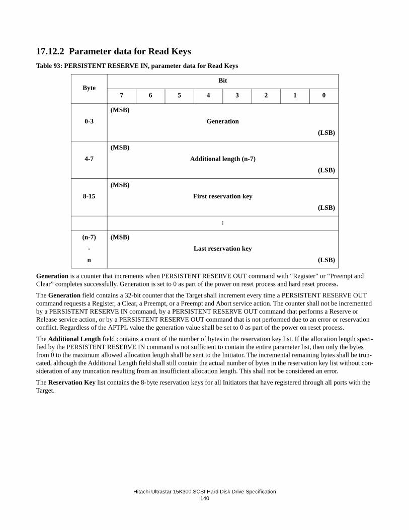
Hitachi Ultrastar 15K300 SCSI Hard Disk Drive Specification140
17.12.2 Parameter data for Read KeysTable 93: PERSISTENT RESERVE IN, parameter data for Read Keys
Generation is a counter that increments when PERSISTENT RESERVE OUT command with “Register” or “Preempt and Clear” completes successfully. Generation is set to 0 as part of the power on reset process and hard reset process.
The Generation field contains a 32-bit counter that the Target shall increment every time a PERSISTENT RESERVE OUT command requests a Register, a Clear, a Preempt, or a Preempt and Abort service action. The counter shall not be incremented by a PERSISTENT RESERVE IN command, by a PERSISTENT RESERVE OUT command that performs a Reserve or Release service action, or by a PERSISTENT RESERVE OUT command that is not performed due to an error or reservation conflict. Regardless of the APTPL value the generation value shall be set to 0 as part of the power on reset process.
The Additional Length field contains a count of the number of bytes in the reservation key list. If the allocation length speci-fied by the PERSISTENT RESERVE IN command is not sufficient to contain the entire parameter list, then only the bytes from 0 to the maximum allowed allocation length shall be sent to the Initiator. The incremental remaining bytes shall be trun-cated, although the Additional Length field shall still contain the actual number of bytes in the reservation key list without con-sideration of any truncation resulting from an insufficient allocation length. This shall not be considered an error.
The Reservation Key list contains the 8-byte reservation keys for all Initiators that have registered through all ports with the Target.
ByteBit
7 6 5 4 3 2 1 0
0-3
(MSB)
Generation
(LSB)
4-7
(MSB)
Additional length (n-7)
(LSB)
8-15
(MSB)
First reservation key
(LSB)
:
(n-7)
-
n
(MSB)
Last reservation key
(LSB)

Hitachi Ultrastar 15K300 SCSI Hard Disk Drive Specification141
17.12.3 Parameter Data for Read ReservationsTable 94: PERSISTENT RESERVE IN, parameter data for Read Reservations
The Generation field shall be as defined for the Persistent Reserve In Read Keys parameter data. The Additional Length field contains a count of the number of bytes to follow in the Reservation Descriptor(s).
If the Allocation length specified by the PERSISTENT RESERVE IN command is not sufficient to contain the entire param-eter list, then only the bytes from 0 to the maximum allowed allocation length shall be sent to the Initiator. The remaining bytes shall be truncated, although the Additional Length field shall still contain the actual number of bytes of the Reservation Descriptor(s) and shall not be affected by the truncation. This shall not be considered an error.
The format of the Reservation Descriptors is defined in the Persistent Reserve In Reservation Descriptor table. There shall be a Reservation Descriptor for the persistent reservation, if any, present in the Target having a persistent reservation.
Table 95: PERSISTENT RESERVE IN, Read Reservation Descriptor
.The Scope of each persistent reservation created by a PERSISTENT RESERVE OUT command will be returned. See the PERSISTENT RESERVE OUT command section for details.
ByteBit
7 6 5 4 3 2 1 0
0-3
(MSB)
Generation
(LSB)
4-7
(MSB)
Additional length (n-7)
(LSB)
8-n
(MSB)
Reservation descriptors
(LSB)
ByteBit
7 6 5 4 3 2 1 0
0-7(MSB)
Reservation key(LSB)
8-11(MSB)
Scope-specific address(LSB)
12 Reserved
13 Scope=0 Type
14-15(MSB)
Extent Length=0(LSB)

Hitachi Ultrastar 15K300 SCSI Hard Disk Drive Specification142
17.13 PERSISTENT RESERVE OUT (5F)Table 96: PERSISTENT RESERVE OUT (5F)
The PERSISTENT RESERVE OUT command is used to request service actions that reserve the drive for the exclusive or shared use of the initiator. The command uses other service actions to manage and remove such reservations. This command is used in conjunction with the PERSISTENT RESERVE IN command, and should not be used with the RESERVE and RELEASE commands.
Note: If a PERSISTENT RESERVE OUT command is received when a RESERVE is active for the drive, the command will be rejected with Reservation Conflict status.
Parameter List Length must be 18h. If not, Check Condition status will be returned, with sense key of Illegal Request and additional sense code of Parameter List Length Error.
.
ByteBit
7 6 5 4 3 2 1 0
0 Command Code = 5Fh
1 Reserved = 0 Service Action
2 Scope=0 Type
3-6 Reserved = 0
7-8 Parameter List Length = 18h
11 VU = 0 Reserved = 0 FLAG LINK

Hitachi Ultrastar 15K300 SCSI Hard Disk Drive Specification143
17.13.1 Service ActionThe following service action codes are supported.
Table 97: PERSISTENT RESERVE OUT, Service Action Code
17.13.2 TypeThe Type field specifies the characteristics of the persistent reservation being established for all customer data sectors. Thetable below describes the supported types and how read and write commands are handled for each reservation type.
Table 98: PERSISTENT RESERVE OUT, Type Code
Code Name Description
00h Register Register a reservation key
01h Reserve Create a persistent reservation using a reservation key
02h Release Release a persistent reservation
03h Clear Clear all reservation keys and all persistent reservations
04h Preempt Preempt persistent reservations from another Initiator
05h Preempt and Abort Preempt persistent reservations from another Initiator and clear the task set for the preempted Initiator
06h Register and Ignore existing key Register a reservation key
07h-1Fh Reserved Reserved
Code Name Description
0h Reserved Reserved
1h Write Exclusive
Reads Shared: Any initiator may execute commands that transfer from the media. Writes Exclusive: Only the initiator with the reservation may execute com-mands that transfer data to the media; Reservation Conflict status will be returned to other initiators.
2h Reserved Reserved
3h Exclusive Access
Reads Exclusive: Only the initiator with the reserva-tion may execute commands that transfer data from the media; Reservation Conflict status will be returned to other initiators.
Writes Exclusive: Only the initator with the reserva-tion may execute commands that transfer data to the media; Reservation Conflict status will be returned to other initators.
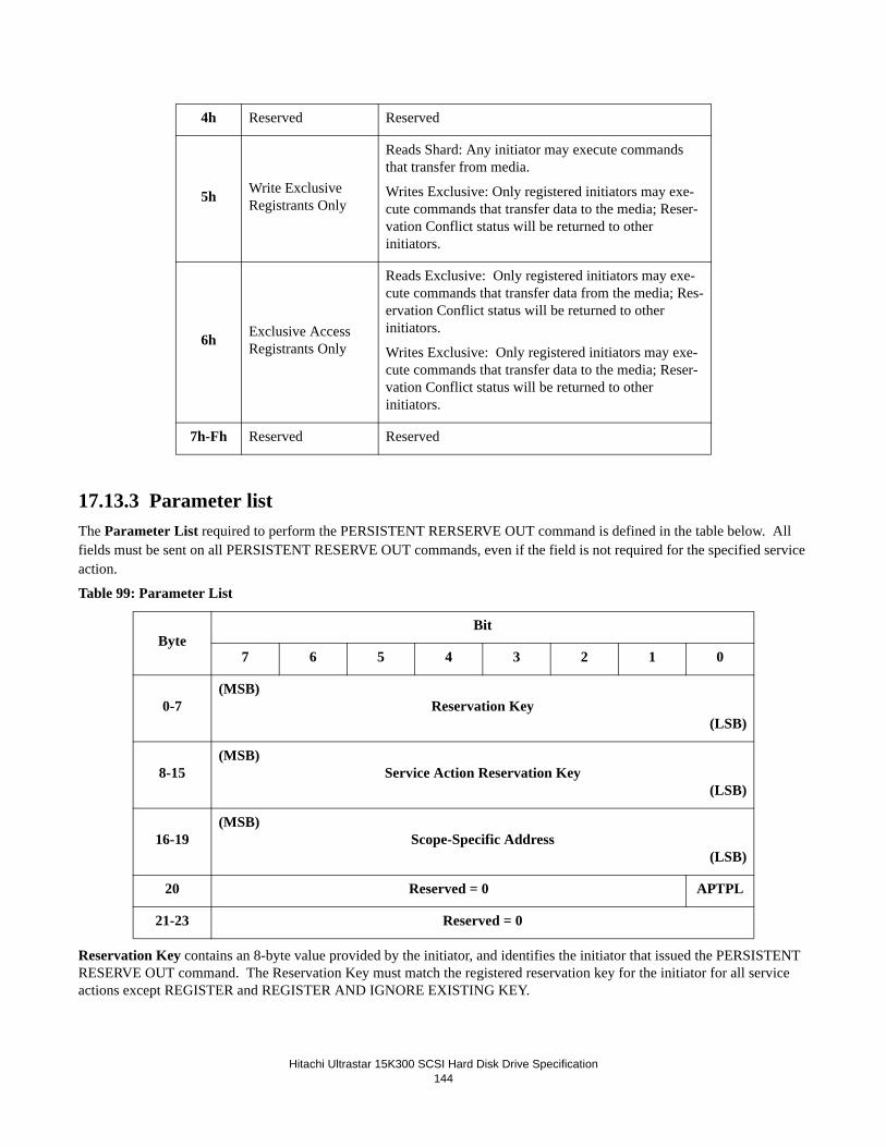
Hitachi Ultrastar 15K300 SCSI Hard Disk Drive Specification144
17.13.3 Parameter listThe Parameter List required to perform the PERSISTENT RERSERVE OUT command is defined in the table below. All fields must be sent on all PERSISTENT RESERVE OUT commands, even if the field is not required for the specified service action.
Table 99: Parameter List
Reservation Key contains an 8-byte value provided by the initiator, and identifies the initiator that issued the PERSISTENT RESERVE OUT command. The Reservation Key must match the registered reservation key for the initiator for all service actions except REGISTER and REGISTER AND IGNORE EXISTING KEY.
4h Reserved Reserved
5h Write Exclusive Registrants Only
Reads Shard: Any initiator may execute commands that transfer from media.
Writes Exclusive: Only registered initiators may exe-cute commands that transfer data to the media; Reser-vation Conflict status will be returned to other initiators.
6h Exclusive Access Registrants Only
Reads Exclusive: Only registered initiators may exe-cute commands that transfer data from the media; Res-ervation Conflict status will be returned to other initiators.
Writes Exclusive: Only registered initiators may exe-cute commands that transfer data to the media; Reser-vation Conflict status will be returned to other initiators.
7h-Fh Reserved Reserved
ByteBit
7 6 5 4 3 2 1 0
0-7(MSB)
Reservation Key(LSB)
8-15(MSB)
Service Action Reservation Key(LSB)
16-19(MSB)
Scope-Specific Address(LSB)
20 Reserved = 0 APTPL
21-23 Reserved = 0

Hitachi Ultrastar 15K300 SCSI Hard Disk Drive Specification145
Service Action Reservation Key contents vary based on the service action. For REGISTER and REGISTER AND IGNORE EXISTING KEY, the Service Action Reservation Key must contain the new reservation key to be registered. For PREEMPT and PREEMPT AND ABORT , the field contains the reservation key of the persistent reservation that is being preempted. This field is ignored for all other service actions.
Scope-Specific Address is ignored.
APTPL (Activate Persist Through Power Loss) bit is valid only for REGISTER and REGISTER AND IGNORE EXIST-ING KEY, and is ignored for all other service actions. If the last valid APTPL bit value received is zero, power loss will cause all persistent reservations to be released, and all reservation keys to be removed. If the last valid APTPL bit value received is one, any persistent reservation and all reservation keys for all initiators will be retained across power cycles.
17.13.4 SummaryTable 100: PERSISTENT RESERVE OUT, Service Action, Parameters
Service Action
ParametersGeneration
counterScope
Type
Rsv
Key
SvcAct
RsvKey
S-spec
addr
Extent
lengthAPTPL
(0) Register ignore verify save ignore ignore apply + 1
(1) Reserve apply verify ignore ignore ignore ignore ---
(2) Release apply verify ignore ignore ignore ignore ---
(5) Preempt and Abort apply verify save ignore ignore ignore + 1
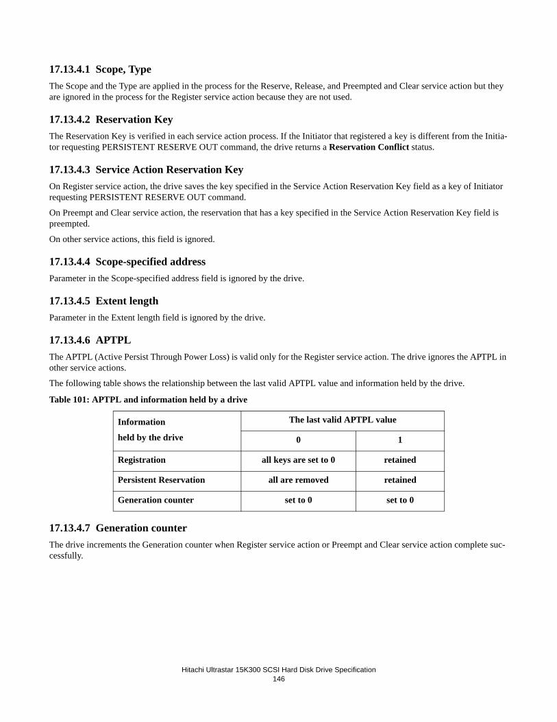
Hitachi Ultrastar 15K300 SCSI Hard Disk Drive Specification146
17.13.4.1 Scope, TypeThe Scope and the Type are applied in the process for the Reserve, Release, and Preempted and Clear service action but they are ignored in the process for the Register service action because they are not used.
17.13.4.2 Reservation KeyThe Reservation Key is verified in each service action process. If the Initiator that registered a key is different from the Initia-tor requesting PERSISTENT RESERVE OUT command, the drive returns a Reservation Conflict status.
17.13.4.3 Service Action Reservation KeyOn Register service action, the drive saves the key specified in the Service Action Reservation Key field as a key of Initiator requesting PERSISTENT RESERVE OUT command.
On Preempt and Clear service action, the reservation that has a key specified in the Service Action Reservation Key field is preempted.
On other service actions, this field is ignored.
17.13.4.4 Scope-specified addressParameter in the Scope-specified address field is ignored by the drive.
17.13.4.5 Extent lengthParameter in the Extent length field is ignored by the drive.
17.13.4.6 APTPLThe APTPL (Active Persist Through Power Loss) is valid only for the Register service action. The drive ignores the APTPL in other service actions.
The following table shows the relationship between the last valid APTPL value and information held by the drive.
Table 101: APTPL and information held by a drive
17.13.4.7 Generation counterThe drive increments the Generation counter when Register service action or Preempt and Clear service action complete suc-cessfully.
Information
held by the drive
The last valid APTPL value
0 1
Registration all keys are set to 0 retained
Persistent Reservation all are removed retained
Generation counter set to 0 set to 0

Hitachi Ultrastar 15K300 SCSI Hard Disk Drive Specification147
17.14 PRE-FETCH (34)Table 102: PRE-FETCH (34)
The PRE-FETCH command requests the drive to transfer data to the cache. No data is transferred to the Initiator.• Transfer length field specifies the number of contiguous blocks of data that are to be transferred into the cache. A
transfer length of zero indicates that blocks are to be transferred into the cache until the segment is filled or until the last block on the media.
• Immed (Immediate) must be zero. An immediate bit of zero indicates that the status shall not be returned until the operation has completed. If the Immed bit is set to one, the drive returns a Check Condition status. The sense key shall be set to Illegal Request and the additional sense code shall be set to Invalid Field in CDB.
ByteBit
7 6 5 4 3 2 1 0
0 Command Code = 34h
1 Reserved = 0 Reserved = 0 Immed = 0
Obso-lete
2-5
(MSB)
Logical Block Address
(LSB)
6 Reserved = 0
7-8(MSB) Transfer Length
(LSB)
9 VU = 0 Reserved = 0 FLAG LINK

Hitachi Ultrastar 15K300 SCSI Hard Disk Drive Specification148
17.15 READ (6) - (08)Table 103: READ (6) - (08)
The READ command requests the drive to transfer from the medium to the initiator the specified number of blocks (Transfer Length) starting at the specified Logical Block Address (LBA).
• Logical block address field specifies the logical unit at which the READ operation shall begin.• Transfer length field specifies the number of blocks to be transferred. A value of zero implies 256 blocks are to be
transferred.
Note: Error recovery procedure (ERP) handles errors. The error recovery parameters specified by the MODE SELECT command control ERPs. If the drive is formatted with protection information, no protection information will be transmitted or checked.
ByteBit
7 6 5 4 3 2 1 0
0 Command Code = 08h
1 Reserved = 0 (MSB) LBA
2-3Logical Block Address
(LSB)
4 Transfer Length
5 VU = 0 Reserved = 0 FLAG LINK

Hitachi Ultrastar 15K300 SCSI Hard Disk Drive Specification149
17.16 READ (10) - (28) Table 104: READ (10) - (28)
The READ (10) command requests the drive to transfer data to the Initiator. The larger LBA and Transfer Length fields permit greater quantities of data to be requested per command than with the READ command and are required to access the full LBA range of the larger capacity drives.
• FUA_NV (F orce Unit Access Non-Volatile Cache) may be set to 0 or 1, but is ignored since NV_SUP=0 in Inquiry Page 86h.
• Transfer length The number of contiguous blocks to be transferred. If the transfer length is zero, the seek occurs, but no data is transferred. This condition is not considered an error. If read ahead is enabled, a read ahead is started after the seek completes.
• DPO (Disable Page Out) bit of one indicates that the data accessed by this command is to be assigned the lowest pri-ority for being written into or retained by the cache. A DPO bit of one overrides any retention priority specified in the Mode Select Page 8 Caching Parameters. A DPO bit of zero indicates the priority is determined by the retention pri-ority. The Initiator should set the DPO bit when the blocks read by this command are not likely to be read again in the near future.
• FUA (Force Unit Access) bit of one indicates that the data is read from the media and not from the cache. A FUA bit of zero allows the data to be read from either the media or the cache.
• RDPROTECT defines the manner in which protection information read from disk shall be checked during process-ing of the command. Protection information is stored on disk, and may be transmitted to the drive's internal data buffer and to the initiator with the user data. If the drive is not formatted with protection information, RDPROTECT must be set to 000b, else Check Condition status will be returned with sense key of Illegal Request and additional sense code of Invalid Field in CDB.
• RDPROTECT=000bProtection information is not transmitted to the initiator and is not checked.
RDPROTECT=001b
ByteBit
7 6 5 4 3 2 1 0
0 Command Code = 28h
1 RDPROTECT DPO FUA Rsvd=0
FUA_NV
Obso-lete
2-5
(MSB)
Logical Block Address
(LSB)
6 Reserved = 0
7-8(MSB) Transfer Length
(LSB)
9 VU = 0 Reserved = 0 FLAG LINK

Hitachi Ultrastar 15K300 SCSI Hard Disk Drive Specification150
- Protection information is transmitted to the initiator with the user data
- Logical Block Guard is checked
- Logcial Block Application Tag is checked (applies to READ(32) command only)
- Logical Block Reference Tag is checked
RDPROTECT=010b- Protection information is transmitted to the initiator with the user data
- Logical Block Guard is not checked
- Logcial Block Application Tag is checked (applies to READ(32) command only)
- Logical Block Reference Tag is checked
RDPROTECT=011b- Protection information is transmitted to the initiator with the user data
- Logical Block Guard is not checked
- Logcial Block Application Tag is not checked
- Logical Block Reference Tag is not checked
RDPROTECT=100b- Protection information is transmitted to the initiator with the user data
- Logical Block Guard is checked
- Logcial Block Application Tag is not checked
- Logical Block Reference Tag is not checked
RDPROTECT=101b, 110b, 111bThese values are reserved. Check Condition status will be returned with sense key of Illegal Request and additional sense code of Invalid Field in CDB.
If a check of the protection information fails, Check Condition status will be returned with sense key of Aborted Command and additional sense code indicating which protection field check failed.
Refer to the ANSI T10 standards for additional details of protection information. If the transfer length is zero, no data is transferred. The CDB is validated and protocol checked and, if no problems are found, Good status is returned immediately. This condition is not considered an error.

Hitachi Ultrastar 15K300 SCSI Hard Disk Drive Specification151
17.17 READ (12) - (A8)Table 105: Read (12) - (A8)
The READ(12) command causes the drive to transfer data to the initiator. See the READ(10) description for the definitions of the fields in this command.
ByteBit
7 6 5 4 3 2 1 0
0 Command Code = A8h
1 RDPROTECT DPO FUA Rsvd = 0
FUA_NV Rsvd = 0
2 - 5
(MSB)
Logical Block Address
(LSB)
6 - 9
(MSB)
Transfer Length
(LSB)
10 Reserved = 0
11 VU = 0 Reserved = 0 FLAG LINK

Hitachi Ultrastar 15K300 SCSI Hard Disk Drive Specification152
17.18 READ (16) - (88)Table 106: READ (16) - (88)
The READ(16) command causes the drive to transfer data to the initiator. See the READ(10) description for the definitions of the fields in this command.
ByteBit
7 6 5 4 3 2 1 0
0 Command Code = 88h
1 RDPROTECT DPO FUA Rsvd=0 FUA_NV Rsvd=0
2 - 5
(MSB)
Logical Block Address
(LSB)
6 - 9
(MSB)
Transfer Length
(LSB)
10 Reserved = 0
11 VU = 0 Reserved = 0 FLAG LINK

Hitachi Ultrastar 15K300 SCSI Hard Disk Drive Specification153
17.19 READ BUFFER (3C)Table 107: READ BUFFER (3C)
The READ BUFFER command is used in conjunction with the WRITE BUFFER command as a diagnostic function for test-ing the memory of the drive and the SCSI bus integrity. This command does not alter the medium.
The function of this command and the meaning of fields within the command descriptor block depend on the contents of the mode field.
MODE Description
00000 Read Combined Header and Data
00010 Read Data
00011 Descriptor
01010 Read Data from Echo Buffer
01011 Echo Buffer Descriptor
11010 Enable Expander Communications Protocol and Echo Buffer
All others Not supported
ByteBit
7 6 5 4 3 2 1 0
0 Command Code = 3Ch
1 Reserved = 0 Mode
2 Buffer ID = 0
3-5
(MSB)
Buffer Offset
(LSB)
6-8(MSB) Allocation Length
(LSB)
9 VU = 0 Reserved = 0 FLAG LINK

Hitachi Ultrastar 15K300 SCSI Hard Disk Drive Specification154
17.19.1 Combined Header And Data (Mode 00000b)In this mode a 4-byte header followed by data bytes is returned to the Initiator during the DATA IN phase. The Buffer ID and the buffer offset field are reserved.
The drive terminates the DATA IN phase when allocation length bytes of header plus data have been transferred or when the header and all available data have been transferred to the Initiator, whichever is less.
The 4-byte READ BUFFER header (see figure below) is followed by data bytes from the data buffer of the drive.
Table 108: Read Buffer Header
The buffer capacity specifies the total number of data bytes that are available in the data buffer of the drive. This number is not reduced to reflect the allocation length nor is it reduced to reflect the actual number of bytes written using the WRITE BUFFER command.
Following the READ BUFFER header the drive will transfer data from its data buffer.
17.19.2 Read Data (Mode 00010b)In this mode, the DATA IN phase contains buffer data.
• Buffer ID field must be set to zero, indicating the data transfer buffer. If another value is specified, the command is terminated with Check Condition status. The drive shall set sense key to Illegal Request and additional sense code to Illegal Field in CDB.
• Buffer Offset specifies the offset of the memory space specified by the Buffer ID. The Initiator should conform to the offset boundary requirements returned in the READ BUFFER descriptor. If the value exceeds the buffer specified, the command is terminated with Check Condition status. The drive shall set sense key to Illegal Request and addi-tional sense code to Illegal Field in CDB.
• Allocation Length The drive terminates the DATA IN phase when allocation length bytes of data have been trans-ferred or when the header and all available data have been transferred to the Initiator, whichever is less.
ByteBit
7 6 5 4 3 2 1
0 RSVD = 0
1-3(MSB) Buffer Capacity
(LSB)

Hitachi Ultrastar 15K300 SCSI Hard Disk Drive Specification155
17.19.3 Descriptor (Mode 00011b)In this mode, a maximum of four bytes of READ BUFFER descriptor information are returned. The drive returns the descrip-tor information for the buffer specified by the Buffer ID.
• Buffer ID field should normally be set to zero, indicating the drive data transfer buffer. If any other value is specified, the drive returns all zeros in the READ BUFFER descriptor.
• Buffer Offset field is reserved.• Allocation Length should be set to four or greater. The drive transfers the allocation length or four bytes of READ
BUFFER descriptor, whichever is less. The allocation length of zero indicates no data is transfered.The allocation length of greater than zero and less than four (size of the Descriptor) is an invalid request and will cause the com-mand to be terminated with Check Condition status. The drive shall set sense key to Illegal Request and additional sense code to Illegal Field in CDB.
The READ BUFFER descriptor is defined in the figure below. Table 109: Read Buffer Description
The value contained in the Buffer Offset field of subsequent WRITE BUFFER and READ BUFFER commands should be a multiple of two to the power of the offset boundary. The offset boundary is always set to nine, which indicates Sector Bound-aries.
ByteBit
7 6 5 4 3 2 1
0 Offset Boundary = 0x09
1-3(MSB) Buffer Capacity
(LSB)

Hitachi Ultrastar 15K300 SCSI Hard Disk Drive Specification156
17.19.4 Read Data from Echo Buffer (Mode 01010b)In this mode the drive transfers data from the echo buffer. The echo buffer will transfer the same data as when the WRITE BUFFER command was issued with the mode field set to echo buffer.
WRITE BUFFER command with the mode field set to echo buffer should be sent prior to the READ BUFFER command; oth-erwise the READ BUFFER command will be terminated with Check Condition status and Illegal Request.
In this mode Read Buffer transfers the specified amount of data or the amount previously written with a Write Buffer using mode 1010b from the echo buffer, whichever is less.
Issuing a Read Buffer mode 1010b before a Write Buffer mode 1010b will cause indeterminate data to be returned.
The most significant two bytes of the Allocation Length are ignored. The specified amount of data transferred should not be larger than the echo buffer capacity. The echo buffer capacity may be determined by using Read Buffer mode 1011b. Any additional data transferred over and above the echo buffer capacity is regarded as indeterminate.
The Buffer ID and Buffer Offset fields are ignored in this mode.
Note: The echo buffer is a separate buffer from the data buffer used with other read buffer modes. It is intended to be used for domain validation purposes.
17.19.5 Echo Buffer Descriptor (Mode 01011b)In this mode, a maximum of four bytes of Read Buffer Descriptor information is returned. The drive returns the descriptor information for the echo buffer. The Buffer Offset field is reserved in this mode and must be zero. The drive transfers the lesser of the allocation length or four bytes of following Echo Buffer Descriptor.
Table 110: Echo Buffer Descriptor
• EBOS (Echo Buffer Overwritten Supported) bit of zero indicates that the echo buffer is shared by all Initiators.• Buffer Capacity field returns the size of the echo buffer in byte aligned to a 4-byte boundary.
17.19.6 Enable Expander Communications Protocol and Echo Buffer (Mode 11010b)
Receipt of a READ BUFFER command with this mode (11010b) causes a communicative expander to enter the expanded communication protocol mode. SCSI target devices that receive a READ BUFFER command with this mode shall process it as if it were a READ BUFFER command with mode 01010b (see 17.17.4 Read Data from Echo Buffer).
ByteBit
7 6 5 4 3 2 1 0
0 Reserved = 0 EBOS=0
1 Reserved = 0
2 Reserved = 0 (MSB) Buffer Capacity
3 Buffer Capacity (LSB)

Hitachi Ultrastar 15K300 SCSI Hard Disk Drive Specification157
17.20 READ CAPACITY (10) - (25)Table 111: READ CAPACITY (10) - (25)
The READ CAPACITY command returns information regarding the capacity of the drive.• Logical Block Address is used in conjunction with the PMI bit.• PMI (Partial Medium Indicator) indicates:
PMI Description
0 The drive returns the last LBA of the drive.
1 The drive returns the last LBA and block length in bytes are that of the LBA after which a substantial delay in data transfer will be encountered. This returned LBA shall be greater than or equal to the LBA specified by the LBA fields in the CDB.
This option provides the information that the Initiator needs to determine the amount of space available on the same track that is accessible without a head switch or seek.
ByteBit
7 6 5 4 3 2 1 0
0 Command Code = 25h
1 Reserved = 0 Reserved = 0 Obso-lete
2-5
(MSB)
Logical Block Address
(LSB)
6-7 Reserved = 0
8 Reserved = 0 PMI
9 VU = 0 Reserved = 0 FLAG LINK

Hitachi Ultrastar 15K300 SCSI Hard Disk Drive Specification158
17.20.0.1 Returned Data FormatThe data returned to the Initiator in response to the READ CAPACITY command is described here. The data is returned in the DATA IN phase.
Table 112: Format of READ CAPACITY command reply
• Block Length specifies the length in bytes of each block of user data (not including protection information).
ByteBit
6 7 5 4 3 2 1 0
0-3
(MSB)
Maximum Logical Block Address
(LSB)
4-7
(MSB)
Block Length
(LSB)

Hitachi Ultrastar 15K300 SCSI Hard Disk Drive Specification159
17.21 READ CAPACITY (16) (9E/10)Table 113: Read Capcity (16) (9E/10)
The READ CAPACITY (16) (9E/10) command returns information regarding the capacity of the drive. This command is pro-cessed like the standard READ CAPACITY (25) command.
17.21.1 Returned Data FormatThe following data is returned to the initiator in the DATA OUT phase.
Table 114: Returned Data Format
• RTO_EN (Reference Tag Own Enable) bit set to one indicates that application client ownership of the Logical Block Reference Tag field in protection information is enabled (i.e. the drive was formatted with protection informa-tion enabled and the RTO_REQ bit was set to one). An RTO_EN bit set to zero indicates that application client own-ership of the Logical Block Reference Tag field in protection information is disabled.
• PROT_EN (Protection Enable) bit set to one indicates that the drive was formatted with protection information enabled. A PROT_EN bit set to zero indicates that the drive was not formatted with protection information enabled.
ByteBit
6 7 5 4 3 2 1 0
0 Command Code = 9Eh
1 Reserved = 0 Service Action = 10h
2-9
(MSB)
Logical Block Address
(LSB)
10-13
(MSB)
Allocation Length
(LSB)
14 Reserved = 0 PMI
15 VU = 0 Reserved = 0 FLAG Link
ByteBit
6 7 5 4 3 2 1 0
0 - 7(MSB)
Maximum Logical Address(LSB)
8 - 11(MSB)
Block Length(LSB)
12 Reserved = 0 RTO_EN PROT_EN
13 - 31 Reserved = 0

Hitachi Ultrastar 15K300 SCSI Hard Disk Drive Specification160
17.22 READ DEFECT DATA (37)Table 115: READ DEFECT DATA (37)
The READ DEFECT DATA command requests that the Target transfer the medium defect data to the Initiator.
If the Target is unable to access any medium defect data it will return a Check Condition status with the appropriate sense key. The sense key will be set to either Medium Error (03h) if a medium error occurred or No Sense (00h) if the list does not exist and the additional sense code will be set to Defect List Error (19h).
• Plist bit set to one indicates that the Target returns the Plist. A Plist bit of zero indicates that the Target shall not return the Plist of defects.
• Glist bit set to one indicates that the Target returns the Glist. A Glist bit of zero indicates that the Target shall not return the Glist.
Note: With both bits set to one Plist and Glist the Target will return both the primary and grown defect lists. With both bits set to zero, the Target will return only a 4-byte Defect List Header.
• Defect List format field is used by the Initiator to indicate the preferred format for the defect list.
The Defect List Format of '100 (Bytes from Index Format)' and '101 (Physical Sector Format)' are supported. If the requested format is not supported by the drive, it will return the defect list in its default format '101' and then termi-nate the command with Check Condition status. The sense key will be set to Recovered Error (01h) and the addi-tional sense code will be set to Defect List Not Found (1Ch).
The drive sends defect list (Defect Descriptors) in a 8-byte Absolute Block Address (ABA) format that follows a four byte Defect List Header.
The Target will transfer all of the Read Defect Data up to the number of bytes allocated by the Initiator.
ByteBit
7 6 5 4 3 2 1 0
0 Command Code = 37h
1 Reserved = 0 Reserved = 0 0
2 Reserved = 0 Plist Glist Defect List Format
3-6 Reserved = 0
7-8(MSB) Allocation Length
(LSB)
9 VU = 0 Reserved = 0 FLAG LINK

Hitachi Ultrastar 15K300 SCSI Hard Disk Drive Specification161
Table 116: Defect List Format
Note: The drive will terminate the Data In phase when the Allocation Length has been transferred or when all available Defect Data has been transferred to the Initiator, whichever is less.
The Read Defect Data contains a 4-byte header followed by zero or more defect descriptors.
Preferred Defect List Format Returned Defect List Format
Block (000b) Physical Sector
Bytes from Index (100b) Bytes from Index
Physical Sector (101b) Physical Sector
Vendor Unique (110b) Physical Sector
Reserved (001b)
Reserved (010b)
Reserved (011b)
Reserved (111b)

Hitachi Ultrastar 15K300 SCSI Hard Disk Drive Specification162
17.22.1 Defect List HeaderTable 117: Defect List Header
17.22.2 Defect List DescriptorTable 118: Defect List Descriptor
Byte
Bit
7 6 5 4 3 2 1 0
Defect List Header
0 Reserved = 0
1 Reserved = 0 Plist Glist Defect List Format
2-3(MSB) Defect List length
(LSB)
Byte
Bit
7 6 5 4 3 2 1 0
Defect List Descriptor
0-7 Defect Descriptor 0
.
8n - (8n+7) Defect Descriptor n
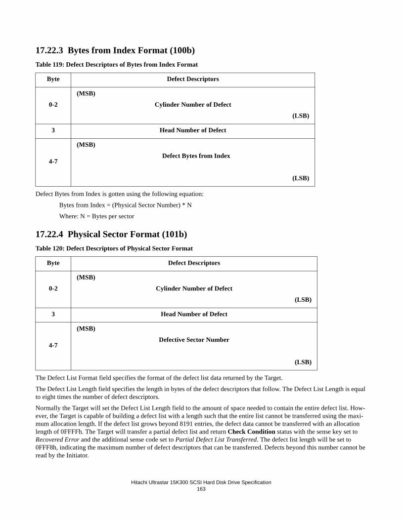
Hitachi Ultrastar 15K300 SCSI Hard Disk Drive Specification163
17.22.3 Bytes from Index Format (100b)Table 119: Defect Descriptors of Bytes from Index Format
Defect Bytes from Index is gotten using the following equation:
Bytes from Index = (Physical Sector Number) * N
Where: N = Bytes per sector
17.22.4 Physical Sector Format (101b)Table 120: Defect Descriptors of Physical Sector Format
The Defect List Format field specifies the format of the defect list data returned by the Target.
The Defect List Length field specifies the length in bytes of the defect descriptors that follow. The Defect List Length is equal to eight times the number of defect descriptors.
Normally the Target will set the Defect List Length field to the amount of space needed to contain the entire defect list. How-ever, the Target is capable of building a defect list with a length such that the entire list cannot be transferred using the maxi-mum allocation length. If the defect list grows beyond 8191 entries, the defect data cannot be transferred with an allocation length of 0FFFFh. The Target will transfer a partial defect list and return Check Condition status with the sense key set to Recovered Error and the additional sense code set to Partial Defect List Transferred. The defect list length will be set to 0FFF8h, indicating the maximum number of defect descriptors that can be transferred. Defects beyond this number cannot be read by the Initiator.
Byte Defect Descriptors
0-2
(MSB)
Cylinder Number of Defect
(LSB)
3 Head Number of Defect
4-7
(MSB)
Defect Bytes from Index
(LSB)
Byte Defect Descriptors
0-2
(MSB)
Cylinder Number of Defect
(LSB)
3 Head Number of Defect
4-7
(MSB)
Defective Sector Number
(LSB)
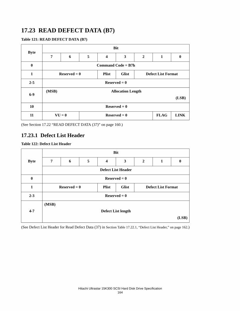
Hitachi Ultrastar 15K300 SCSI Hard Disk Drive Specification164
17.23 READ DEFECT DATA (B7)Table 121: READ DEFECT DATA (B7)
(See Section 17.22 “READ DEFECT DATA (37)” on page 160.)
17.23.1 Defect List HeaderTable 122: Defect List Header
(See Defect List Header for Read Defect Data (37) in Section Table 17.22.1, “Defect List Header,” on page 162.)
ByteBit
7 6 5 4 3 2 1 0
0 Command Code = B7h
1 Reserved = 0 Plist Glist Defect List Format
2-5 Reserved = 0
6-9(MSB) Allocation Length
(LSB)
10 Reserved = 0
11 VU = 0 Reserved = 0 FLAG LINK
Byte
Bit
7 6 5 4 3 2 1 0
Defect List Header
0 Reserved = 0
1 Reserved = 0 Plist Glist Defect List Format
2-3 Reserved = 0
4-7
(MSB)
Defect List length
(LSB)

Hitachi Ultrastar 15K300 SCSI Hard Disk Drive Specification165
17.23.2 Defect List DescriptorTable 123: Defect List Descriptor
(See Defect List Descriptor for Read Defect Data (37) in Section 17.22.2 “Defect List Descriptor” on page 162.)
17.23.3 Bytes from Index Format (100b)Table 124: Defect Descriptors of Bytes from Index Format
Defect Bytes from Index is derived using the following equation:Bytes from Index = (Physical Sector Number) + N
where N = Bytes per sector.
17.23.4 Physical Sector Format (101b)Table 125: Defect Descriptors of Physical Sector Format
Byte
Bit
7 6 5 4 3 2 1 0
Defect List Descriptor
0-7 Defect Descriptor 0
.
8n - (8n+7) Defect Descriptor n
Byte Defect Descriptors
0-2
(MSB)
Cylinder Number of Defect
(LSB)
3 Head Number of Defect
4-7
(MSB)
Defect Bytes from Index
(LSB)
Byte Defect Descriptors
0-2
(MSB)
Cylinder Number of Defect
(LSB)
3 Head Number of Defect
4-7
(MSB)
Defective Sector Number
(LSB)

Hitachi Ultrastar 15K300 SCSI Hard Disk Drive Specification166
17.24 READ LONG (3E)Table 126: READ LONG (3E)
The READ LONG command requests the drive to transfer one block of data to the Initiator. The transfer data includes data and ECC field data.
• Correct bit of zero causes the logical block to be read without any correction attempts. When the bit is one, data will be corrected with offline ECC correction before being transferred.
• Logical Block Address field specifies the logical block at which the read operation shall occur.• Byte Transfer Length field must specify exactly the number of bytes of data that are available for transfer. If a non-
zero byte transfer length does not match the available data length, the Target terminates the command with Check Condition status, the sense key is set to Illegal Request, and an additional sense code set to Invalid Field in CDB. The valid and ILI bits are set to one and the information field is set to the difference of the requested length minus the actual length in bytes. Negative values are indicated by two's complement notation.
The transfer length is calculated as follows:
transfer length = logical block size + 56
The data read by this command is neither read from nor retained in the cache.
ByteBit
7 6 5 4 3 2 1 0
0 Command Code = 3Eh
1 Reserved = 0 Reserved = 0Cor-rect
= 0
Obso-lete
2-5
(MSB)
Logical Block Address
(LSB)
6 Reserved = 0
7-8(MSB) Byte Transfer Length
(LSB)
9 VU = 0 Reserved = 0 FLAG LINK

Hitachi Ultrastar 15K300 SCSI Hard Disk Drive Specification167
17.25 REASSIGN BLOCKS (07)Table 127: REASSIGN BLOCKS (07)
The REASSIGN BLOCKS command requests the drive to reassign a logical block to an available spare. The REASSIGN BLOCKS command attempts to allocate spare blocks on a spare track. The LBA is transferred to the drive during the DATA OUT phase. One to four blocks may be specified for relocation per REASSIGN BLOCKS command.
Reassignment is complete upon the completion of the REASSIGN BLOCKS command. At this time, the defective logical block address has been added to the Glist.
All data is preserved during a reassign command except for the target LBA data. The Mode Page 0h DRRT (Disable Restore Reassign Target) bit determines if the reassign blocks command will attempt to recover the Target LBA data. If the Target can-not recover the data at the Target LBA then the Initiator will have to restore the data after the REASSIGN BLOCKS command completes successfully.
If the reassignment begins to move data and is interrupted or fails to complete successfully, the Target enters a degraded mode of operation. In this mode data can be read but writing to the drive is prohibited.
Upon successful completion of this command, the location of the physical sectors reassigned during the command are added to the Glist. The reassigned sectors are marked defective and cannot be accessed again until after a format operation discards the Glist.
ByteBit
7 6 5 4 3 2 1 0
0 Command Code = 07h
1 Reserved = 0 Reserved = 0
2
3
4
Reserved = 0
5 VU = 0 Reserved = 0 FLAG LINK

Hitachi Ultrastar 15K300 SCSI Hard Disk Drive Specification168
Following is the format of the data sent by the Initiator during the DATA OUT phase.
Table 128: Format of Reassign Blocks data
• Defect List Length must be 4, 8, 12, or 16. Otherwise, the drive returns Check Condition with a sense key of Illegal Request.
• Defective Logical Block Address is four bytes in length. The Initiator can specify from 1 to 4 Defective Logical Block Addresses according to the Defect List Length from 4 to 16, respectively. LBAs are not required to be in ascending order.
ByteBit
7 6 5 4 3 2 1
0 Reserved = 0
1 Reserved = 0
2-3(MSB) Defect List Length = 4/8/12/16
(LSB)
4-7
(MSB)
Defect Logical Block Address 1
(LSB)
8-11
(MSB)
Defect Logical Block Address 2
(LSB)
12-15
(MSB)
Defect Logical Block Address 3
(LSB)
16-19
(MSB)
Defect Logical Block Address 4
(LSB)

Hitachi Ultrastar 15K300 SCSI Hard Disk Drive Specification169
17.26 RECEIVE DIAGNOSTICS RESULTS (1C)Table 129: RECEIVE DIAGNOSTIC RESULTS (1C)
The RECEIVE DIAGNOSTIC RESULTS command requests that analysis data requested by a SEND DIAGNOSTIC com-mand be sent to the Initiator.
• PCV (Page Code Valid) bit of zero indicates that the most recent SEND DIAGNOSTIC command shall define the data returned by this command. PCV bit of one indicates that the contents of the Page Code field shall define the data returned by this command.
• Allocation Length specifies the amount of data to be returned to the Initiator. This value may be zero and this is not considered an error. The Target terminates the Data In phase when all available data has been transferred or when the number of bytes transferred equals the Parameter List Length.
17.26.1 Receive Diagnostic Results Page 0This page contains a list of supported pages.
Table 130: Receive Diagnostic Results page 0
The supported diagnostic page returns a list of supported pages in ascending order.
ByteBit
7 6 5 4 3 2 1 0
0 Command Code = 1Ch
1 Reserved = 0 Reserved = 0 PCV
2 Page Code
3
4
(MSB) Allocation Length
(LSB)
5 VU = 0 Reserved = 0 FLAG LINK
ByteBit
7 6 5 4 3 2 1 0
0 Page Code = 0
1 Reserved = 0
2-3 Page Length = 02h
4 (Supported Pages) Page = 02h
5 Translate address page = 40h

Hitachi Ultrastar 15K300 SCSI Hard Disk Drive Specification170
17.26.2 Receive Diagnostic Results Page 40Using the SEND DIAGNOSTIC command, an address in either physical or logical format is supplied to the drive. This page is then used to retrieve the address translated into the other format.
Table 131: Receive Diagnostic Results Page 40
• Page Length is set to 02h if the address is in a Reserved Area (RA =1). Otherwise, Page Length is set to 06h if the Translate Format is Block format, or 0Ah if the Translate Format is Bytes From Index format or Physical Sector for-mat.
• Supplied Format is the value supplied by the SEND DIAGNOSTIC command; it may be one of the three following values:
- 000b Block format
- 100b Bytes From Index format
- 101b Physical Sector format• Translate Format is the value supplied by the SEND DIAGNOSTIC command and specifies the format in which the
address has been translated into List. If the supplied format is the Block format, the Translate format must be either Bytes from Index or Physical Sector format. If the supplied format is the Bytes from Index or Physical Sector format, the Translate format must be Block format. Otherwise the Target will terminate the command with Check Condition status.
• RA (Reserved Area) is set to on if the translated block is an inaccessible sector, which could reflect a defect, an unused sector on a spare cylinder, or a sector beyond the Maximum Customer LBA.
• ALTS (Alternate Sector) is set to one if the translated block is a sector in a spare cylinder that points to a reassigned customer sector.
• ALTT (Alternate Track) is not used. • Translated Address contains the address in the translate format. If it is an LBA, it is contained within the first four
bytes of the field (bytes 6 to 9) of the page data. For a physical format it is as follows:
Byte Bit
7 6 5 4 3 2 1 0
0 Page Code = 40h
1 Reserved = 0
2-3 Page Length = 0Ah
4 Reserved = 0 Supplied format
5 RA ALTS ALTT Reserved=0 Translate format
6-n Translated Address

Hitachi Ultrastar 15K300 SCSI Hard Disk Drive Specification171
Table 132: Translated address
ByteBit
7 6 5 4 3 2 1 0
6-8 Cylinder Number
9 Head Number
10-13 Sector Number or Bytes from Index

Hitachi Ultrastar 15K300 SCSI Hard Disk Drive Specification172
17.27 RELEASE (17)Table 133: RELEASE (17)
The RELEASE command is used to release a LUN previously reserved. It is not an error for an Initiator to release a LUN that is not currently active. The drive returns Good status without altering the reservation.
• 3rdPty must be 0. Third Party reservations are not supported. If the 3rdPty bit is not zero, Check Condition status is returned with a sense key of Illegal Request and additional sense code of Invalid Field in CDB.
• 3rd Party ID is ignored.• Extents must be 0. Extension is not supported by the drive.• Reservation Identification field is ignored.
ByteBit
7 6 5 4 3 2 1 0
0 Command Code = 17h
1 Reserved = 0 3rdPty=0 3rd Party ID Ext=0
2 Reservation Identification
3-4 Reserved = 0
5 VU = 0 Reserved = 0 FLAG LINK

Hitachi Ultrastar 15K300 SCSI Hard Disk Drive Specification173
17.28 RELEASE (57)Table 134: RELEASE (57)
The RELEASE command is used to release a LUN previously reserved. It is not an error for an Initiator to release a LUN that is not currently active. The drive returns Good status without altering the reservation.
• 3rdPty must be 0. Third Party reservations are not supported. If the 3rdPty bit is not zero, Check Condition status is returned with a sense key of Illegal Request and additional sense code of Invalid Field in CDB.
• 3rd Party ID is ignored.• Extents must be 0. Extension is not supported by the drive.• Reservation Identification field is ignored.
ByteBit
7 6 5 4 3 2 1 0
0 Command Code = 57h
1 Reserved = 0 3rdPty=0 Reserved = 0 Ext = 0
2 Reservation Identification
3 3rd Party Device ID
4-8 Reserved = 0
9 VU = 0 Reserved = 0 FLAG LINK

Hitachi Ultrastar 15K300 SCSI Hard Disk Drive Specification174
17.29 REPORT DEVICE IDENTIFIER (A3/05)Table 135: REPORT DEVICE IDENTIFIER (A3/05)
The REPORT DEVICE IDENTIFIER command requests that the device server send device identification information to the application client.
The LUN contains the logical unit number parameter. This parameter is expected to be zero. Other value for this parameter will cause the command to terminate with a CHECK CONDITION status. The sense key is set to ILLEGAL REQUEST, and the additional sense code is set to INVALID FIELD IN CDB.
The ALLOCATION LENGTH field indicates how much space has been reserved for the returned parameter data. If the length is not sufficient to contain all the parameter data, the first portion of the data is returned. This is not considered an error. The actual length of the parameter data is available in the IDENTIFIER LENGTH field in the parameter data. If the remainder of the parameter data is required, the application client should send a new REPORT DEVICE IDENTIFIER command with an ALLOCATION LENGTH field large enough to contain all the data.
The REPORT DEVICE IDENTIFIER parameter list contains a 4-byte field that contains the length in bytes of the parameter list and the logical unit's identifier.
ByteBit
7 6 5 4 3 2 1 0
0 Command Code = A3h
1 Reserved = 0 Service Action = 05h
2 Reserved = 0
3 Reserved = 0
4-5
(MSB)
LUN=0
(LSB)
6-9
(MSB)
Allocation Length
(LSB)
10 Reserved = 0
11 VU = 0 Reserved = 0 FLAG LINK

Hitachi Ultrastar 15K300 SCSI Hard Disk Drive Specification175
Table 136: Report Device Identifier parameter list
The IDENTIFIER LENGTH field specifies the length in bytes of the IDENTIFIER field. If the ALLOCATION LENGTH field in the CDB is too small to transfer all of the identifier, the length is not adjusted to reflect the truncation. The identifier length initially equals zero and is changed only by a successful SET DEVICE IDENTIFIER command.
The IDENTIFIER field contains a vendor specific value. The value reported is the last value written by a successful SET DEVICE IDENTIFIER command. The value of the identifier is changed only by a SET DEVICE IDENTIFIER command. The identifier value persist through resets, power cycles, media format operations.
The Target return the same Identifier to all Initiators on all ports.
The execution of a REPORT DEVICE IDENTIFIER requires the enabling of a nonvolatile memory within the logical unit. If the nonvolatile memory is not ready, the device server returns Check Condition status rather than wait for the device to become ready. The sense key is set to Not Ready and the additional sense data is set as described in the TEST UNIT READY command. This information should allow the application client to determine the action required to cause the device server to become ready.
ByteBit
7 6 5 4 3 2 1 0
0-3(MSB) Identifier Length = n - 3
(LSB)
4-n Identifier

Hitachi Ultrastar 15K300 SCSI Hard Disk Drive Specification176
17.30 REPORT LUNS (A0)Table 137: REPORT LUNS (A0)
The REPORT LUNS command requests that the Target return the known LUN to the Initiator. The REPORT LUNS command should always be available and is unaffected by any reservations.
The Allocation Length must be at least 16 bytes. If the Allocation Length is less than 16 bytes, the Target will return a Check Condition status with sense key of Illegal Request and additional sense code of Invalid Field in CDB. If the Allocation Length is not sufficient to contain the LUN values for all configured logical units, the Target shall report as many LUN values as will fit in the specified Allocation Length. This is not considered an error.
The REPORT LUNS command will send the LUN list in the subsequent Data Out Phase. The format of the LUN list is shown in the following table.
Table 138: LUN Reporting parameter list format
The LUN list length shall contain the length in bytes of the LUN list that is available to be transferred. This product only sup-ports one LUN. Therefore, the LUN list length must be set to 8. The only supported LUN is zero.
ByteBit
7 6 5 4 3 2 1 0
0 Command Code = A0h
1-5 Reserved
6-9
(MSB)
Allocation Length
(LSB)
10 Reserved
11 VU = 0 Reserved = 0 FLAG LINK
ByteBit
7 6 5 4 3 2 1 0
0-3(MSB) LUN List Length = 8
(LSB)
4-7 Reserved
8-15
(MSB)
LUN = 0
(LSB)

Hitachi Ultrastar 15K300 SCSI Hard Disk Drive Specification177
17.31 REPORT SUPPORTED OPERATION CODES (A3/0C)
The REPORT SUPPORTED OPERATION CODES command requests information on commands that the drive supports. The initiator may request a list of all operation codes and service actions supported, or the command support data for a specific command.
Reporting Options specifies the information to be returned in the parameter data.
Requested Operation Code specifies the operation code of the command to be returned in the one_command parameter data format.
Requested Service Action specifies the service action of the command to be returned in the one_command parameter data format.
ByteBit
7 6 5 4 3 2 1 0
0 Command Code = A3h
1 Reserved = 0 Service Action = 0Ch
2 Reserved = 0 Reporting Options
3 Requested Operation Code
4-5 Requested Service Action
6-9 Allocation Length
10 Reserved = 0
11 VU = 0 Reserved = 0 FLAG LINK
Reporting Options Description
000bA list of all operation codes and service actions supported by the drive will be returned in the all_commands parameter data format. The Requested Operation Code field and Requested Service Action field will be ignored.
001b
The command support data for the operation code specified in the Requested Operation Code field will be returned in the one_command parameter data format. The Requested Service Action field will be ignored. If the Requested Operation Code field specifies an operation code that has service actions, Check Condition status will be reported with a sense key of Illegal Request and additional sense code of Invalid Field in CDB.
010b
The command support data for the operation code and service action specified in the Requested Operation Code field and Requested Service Action field will be returned in the one_command parameter data format. If the Requested Operation Code field speci-fies an operation code that does not have service actions, Check Condition status will be reported with a sense key of Illegal Request and additional sense code of Invalid Field in CDB.
011b-111b Reserved

Hitachi Ultrastar 15K300 SCSI Hard Disk Drive Specification178
Allocation Length specifies the number of bytes that have been allocated for the returned parameter data. If the length is not sufficient to contain all the parameter data, the first portion of the data shall be returned. The actual length of the parameter data may be determined from the Additional Length field in the parameter data.
17.31.1 All_commands parameter data formatThe Report Supported Operation Codes all_command parameter data format begins with a four-byte header that contains the length in bytes of the parameter data, followed by a list of supported commands. Each command descriptor contains informa-tion about a single supported command CDB (i.e. one operation code and service action combination, or one non-service-action operation code).
Each Command Descriptor contains information about a single supported command CDB.
Operation Code contains the operation code of a supported command.
Service Action contains a supported serivce action of the supported operation. If the operation code does not have a service action, the Service Action field will be set to zero.
SERVACTV set to zero indicates the operation code does not have service actions and the Service Action field should be ignored. SERVACTV set to one indicates the operation code field has service actions and the contents of the Service Action field are valid.
CDB Length contains the length of the command CDB in bytes.
ByteBit
7 6 5 4 3 2 1 0
0-3 Command Data Length (n-3)
4 Command Descriptor 0
N Command Descriptor X
ByteBit
7 6 5 4 3 2 1 0
0 Operation Code
1 Reserved = 0
2-3 Service Action
4 Reserved = 0
5 Reserved = 0 SERVACTV
6-7 CDB Length

Hitachi Ultrastar 15K300 SCSI Hard Disk Drive Specification179
17.31.2 One_command parameter data formatThe Report Supported Operation Codes one_command parameter data format contains information about the CDB and a usage map for bits in the CDB for the command specified by the Reporting Options, Requested Operation Code, and Requested Ser-vice Action fields in the Reported Supported Operation Codes CDB.
The Support field is defined in the table below.
CDB Size contains the size of the CDB Usage Data field in the parameter data, and the number of bytes in the CDB for the command requested.
CDB Usage Data contains information about the CDB for the command requested. The first byte of the CDB Usage Data field contains the operation code for the command. If the command contains a service action, then that service action code is returned in the same location as the Service Action field of the command CDB. All other bytes of the CDB Usage Data field contain a usage map for bits in the CDB for the command requested.
The bits in the usage map have a one-for-one correspondence to the CDB for the command requested. If the drive evaluates a bit in the CDB, the usage map will contain a one in the corresponding bit position. The usage map will contain a zero in the corresponding bit position for any field treated as ignored or reserved.
ByteBit
7 6 5 4 3 2 1 0
0 Reserved = 0
1 Reserved = 0 Support
2-3 CDB Size (n-3)
4-n CDB Usage Data
Recording Option Description
000b Data about the requested command is not currently available. All data after byte 1 is not valid. A subsequent request for command support data may be successful.
001b The requested command is not supported. All data after byte 1 is not valid.
010b Reserved.
011b The requested command is supported in conformance with the standard.
100b Reserved
101b The requested command is supported in a vendor specific manner.
110b-111b Reserved.

Hitachi Ultrastar 15K300 SCSI Hard Disk Drive Specification180
17.32 REPORT SUPPORTED TASK MANAGEMENT FUNCTIONS (A3/0D)Table 139: Report Supported Tasks Management Functions (A3/0D)
The REPORT SUPPORTED TASK MANAGEMENT FUNCTIONS command requests information on task management functions supported by the drive.
Allocation Length specifies the number of bytes that have been allocated for the returned parameter data. The allocation length must be at least four. If the allocation length is less than four, Check Condition Status will be returned with sense key of Illegal Request and additional sense code of Invalid Field in CDB.
The format of the returned parameter data is shown below.
ATS (Abort Task) bit set to one indicates that ABORT TASK is supported. An ATS bit of zero indicates that ABORT TASK is not supported.
ATSS (Abort Task Set) bit set to one indicates that ABORT TASK SET is supported. An ATSS bit of zero indicates that ABORT TASK SET is not supported.
CACAS (Clear ACA) bit set to one indicates that CLEAR ACA is supported. A CACAS bit of zero indicates that CLEAR ACA is not supported.
CTSS (Clear Task Set) bit set to one indicates that CLEAR TASK SET is supported. A CTSS bit of zero indicates that CLEAR TASK SET is not supported.
LURS (Logical Unit Reset) bit set to one indicates that LOGICAL UNIT RESET is supported. An LUR bit of zero indicates that LOGICAL UNIT RESET is not supported.
QTS (Query Task) bit set to one indicates that QUERY TASK is supported. A QTS bit of zero indicates that QUERY TASK is not supported.
TRS (Target Reset) bit set to one indicates that TARGET RESET is supported. A TRS bit of zero indicates that TARGET RESET is not supported.
ByteBit
7 6 5 4 3 2 1 0
0 Command Code = A3h
1 Reserved = 0 Service Action = 0Dh
2-5 Reserved = 0
6-9 Allocation Length
10 Reserved = 0
11 VU = 0 Reserved = 0 Flag Link
ByteBit
7 6 5 4 3 2 1 0
0 ATS ATSS CACAS CTSS LURS QTS TRS WAKES
1-3 Reserved = 0
Hitachi Ultrastar 15K300 SCSI Hard Disk Drive Specification181
WAKES (Wakeup) bit set to one indicates that WAKEUP is supported. A WAKES bit of zero indicates that WAKEUP is not supported.

Hitachi Ultrastar 15K300 SCSI Hard Disk Drive Specification182
17.33 REQUEST SENSE (03)Table 140: REQUEST SENSE (03)
The REQUEST SENSE command requests the drive to transfer sense data.
If REQUEST SENSE command with an invalid LUN is received, the drive returns Good status and reports a sense key of Ille-gal Request and an additional sense code of Logical Unit Not Supported.
If the drive has no sense data available to return, it shall return a sense key of No Sense and an additional sense code of No Additional Sense Information.
Separate sense data is maintained by the device for each Initiator. Therefore, there is no requirement for an Initiator to expedi-tiously clear a Check Condition as this will not affect other initiators in a multi-Initiator system.
The drive will return the number of bytes in the allocation length or 32 bytes, whichever is less.
ByteBit
7 6 5 4 3 2 1 0
0 Command Code = 03h
1 Reserved = 0 Reserved = 0
2-3 Reserved = 0
4 Allocation Length
5 VU = 0 Reserved = 0 FLAG LINK
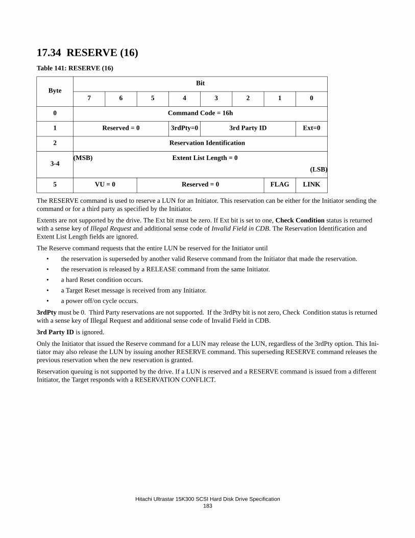
Hitachi Ultrastar 15K300 SCSI Hard Disk Drive Specification183
17.34 RESERVE (16)Table 141: RESERVE (16)
The RESERVE command is used to reserve a LUN for an Initiator. This reservation can be either for the Initiator sending the command or for a third party as specified by the Initiator.
Extents are not supported by the drive. The Ext bit must be zero. If Ext bit is set to one, Check Condition status is returned with a sense key of Illegal Request and additional sense code of Invalid Field in CDB. The Reservation Identification and Extent List Length fields are ignored.
The Reserve command requests that the entire LUN be reserved for the Initiator until• the reservation is superseded by another valid Reserve command from the Initiator that made the reservation.• the reservation is released by a RELEASE command from the same Initiator.• a hard Reset condition occurs.• a Target Reset message is received from any Initiator.• a power off/on cycle occurs.
3rdPty must be 0. Third Party reservations are not supported. If the 3rdPty bit is not zero, Check Condition status is returned with a sense key of Illegal Request and additional sense code of Invalid Field in CDB.
3rd Party ID is ignored.
Only the Initiator that issued the Reserve command for a LUN may release the LUN, regardless of the 3rdPty option. This Ini-tiator may also release the LUN by issuing another RESERVE command. This superseding RESERVE command releases the previous reservation when the new reservation is granted.
Reservation queuing is not supported by the drive. If a LUN is reserved and a RESERVE command is issued from a different Initiator, the Target responds with a RESERVATION CONFLICT.
ByteBit
7 6 5 4 3 2 1 0
0 Command Code = 16h
1 Reserved = 0 3rdPty=0 3rd Party ID Ext=0
2 Reservation Identification
3-4(MSB) Extent List Length = 0
(LSB)
5 VU = 0 Reserved = 0 FLAG LINK

Hitachi Ultrastar 15K300 SCSI Hard Disk Drive Specification184
17.35 RESERVE (56)Table 142: RESERVE (56)
The RESERVE command is used to reserve a LUN for an Initiator. This reservation can be either for the Initiator sending the command or for a third party as specified by the Initiator.
Extents are not supported by the drive. The Ext bit must be zero. If Ext bit is set to one, Check Condition status is returned with a sense key of Illegal Request and additional sense code of Invalid Field in CDB. The Reservation Identification and Extent List Length fields are ignored.
The Reserve command requests that the entire LUN be reserved for the Initiator until• the reservation is superseded by another valid Reserve command from the Initiator that made the reservation.• the reservation is released by a RELEASE command from the same Initiator.• a hard Reset condition occurs.• a Target Reset message is received from any Initiator.• a power off/on cycle occurs.
3rdPty must be 0. Third Party reservations are not supported. If the 3rdPty bit is not zero, Check Condition status is returned with a sense key of Illegal Request and additional sense code of Invalid Field in CDB.
3rd Party ID is ignored.
Only the Initiator that issued the Reserve command for a LUN may release the LUN, regardless of the 3rdPty option. This Ini-tiator may also release the LUN by issuing another RESERVE command. This superseding RESERVE command releases the previous reservation when the new reservation is granted.
Reservation queuing is not supported by the drive. If a LUN is reserved and a RESERVE command is issued from a different Initiator, the Target responds with a RESERVATION CONFLICT.
ByteBit
7 6 5 4 3 2 1 0
0 Command Code = 56h
1 Reserved = 0 3rdPty=0 Reserved Ext=0
2 Reservation Identification
3 Third Pay Device ID
4-6 Reserved = 0
7-8(MSB) Extent List Length = 0
(LSB)
9 VU = 0 Reserved = 0 FLAG LINK

Hitachi Ultrastar 15K300 SCSI Hard Disk Drive Specification185
17.36 REZERO UNIT (01)Table 143: REZERO UNIT (01)
The REZERO UNIT command requests that the Target seek LBA 0.
ByteBit
7 6 5 4 3 2 1 0
0 Command Code = 01h
1 Reserved = 0 Reserved = 0
2-4 Reserved = 0
5 VU = 0 Reserved = 0 FLAG LINK

Hitachi Ultrastar 15K300 SCSI Hard Disk Drive Specification186
17.37 SEEK (6) - (0B)Table 144: SEEK (6) - (0B)
The SEEK (6) command requests the drive to seek the specified LBA. If the LBA is greater than the value returned by the READ CAPACITY command, the Drive returns a Check Condition status with a sense key of Illegal Request and an addi-tional sense code of Invalid Field in CDB.
17.38 SEEK (10) - (2B)Table 145: SEEK (10) - (2B)
The SEEK (10) command requests the drive to seek the specified LBA. If the LBA is greater than the value returned by the READ CAPACITY command, the Drive returns a Check Condition status with a sense key of Illegal Request and an addi-tional sense code of Invalid Field in CDB.
ByteBit
7 6 5 4 3 2 1 0
0 Command Code = 0Bh
1 Reserved = 0 (MSB) LBA
2
3
Logical Block Address
(LSB)
4 Reserved = 0
5 VU = 0 Reserved = 0 FLAG LINK
ByteBit
7 6 5 4 3 2 1 0
0 Command Code = 2Bh
1 Reserved = 0 Reserved = 0 0
2-5
(MSB)
Logical Block Address
(LSB)
6-8 Reserved = 0
9 VU = 0 Reserved = 0 FLAG LINK

Hitachi Ultrastar 15K300 SCSI Hard Disk Drive Specification187
17.39 SEND DIAGNOSTIC (1D)Table 146: SEND DIAGNOSTIC (1D)
The SEND DIAGNOSTIC command requests the drive to perform its self-diagnostic test or to perform a function based on a page of information sent in a Data Out phase during the command.
• PF (Page Format) bit set to one indicates the data sent by the Initiator conform to the page structure as specified in SCSI standard. This bit must be set to one if the SlfTst bit is set to zero. This bit is ignored by the Target if the SlfTst bit is set.
• SlfTst set to one indicates that the device performs its default self-test. If SlfTst is one, the Function code field is ignored. If SlfTst is set to zero, the action to perform is specified in Function code field.
ByteBit
7 6 5 4 3 2 1 0
0 Command Code = 1Dh
1 Function Code PF RSVD =0 SlfTst Dev0fl Unt0fl
2 Reserved = 0
3-4(MSB) Parameter List Length
(LSB)
5 VU = 0 Reserved = 0 FLAG LINK

Hitachi Ultrastar 15K300 SCSI Hard Disk Drive Specification188
Table 147: SEND DIAGNOSTIC Function Code (1D)
• DevOfl is ignored by the Target for compatibility.• UntOfl is ignored by the Target for compatibility.• Parameter List Length must be 0 when the SlfTst bit is one. Otherwise, Check Condition status will be generated
with a sense key of Illegal Request and additional sense of Invalid Field in CDB. If the SlfTst bit is zero, it should be set to the length of the page to be transferred in the DATA OUT phase of the command. If it does not match the expected length of the page a Check Condition status will be also generated with a sense key of Illegal Request and additional sense of Invalid Field in CDB.
If the motor is not running at the correct speed when the command is received, it is rejected by a Check Condition status with a Not Ready sense key.
If a fault is detected during the default or foreground self-test, a Check Condition is reported as an end status. If a fault is detected during the background self-test, it is logged in the log page for later retrieval by a LOG SENSE command.
See Section 20.17 “Diagnostics” on page 246, for detailed listing of operations carried out by SEND DIAGNOSTIC command and Power on Diagnostics.
Value Function name Description
000b NAValue to be used when the SlfTst bit is set to one or if the SEND DIAGNOSTIC command is not invoking one of the other self-test function codes.
001b Background Short self-test The device server starts its short self-test routine in back-ground mode.
010b Background extended self-test The device server starts its extended self-test routine in background mode.
011b NA Reserved.
100b Abort background self-test
Abort the current self-test in the background mode. This value is only valid if a previous SEND DIAGNOSTIC com-mand specified a background self-test function and that function has not been completed.
101b Foreground short self-testThe device server starts its short self-test routine in the fore-ground mode. This self-test will complete in two minutes or less.
110b Foreground extended self-testThe device server starts its extended self-test routine in the foreground mode. The completion for this test is reported in Mode Page 0Ah (refer to section 17.11.9 Mode Page 0Ah).
111b Reserved.

Hitachi Ultrastar 15K300 SCSI Hard Disk Drive Specification189
17.39.1 Send Diagnostic Page 0This page requests that the drive return a list of supported pages on the next RECEIVE DIAGNOSTICS command.
Table 148: Diagnostic Page 0
17.39.2 Send Diagnostic Page 40This allows the Initiator to translate a LBA or physical sector address to the other format. The address to be translated is passed to the Target with the SEND DIAGNOSTIC command and the results are returned to the Initiator by the RECEIVE DIAG-NOSTICS command.
The Target will read the parameter list from the Initiator, and, if no errors are detected in the parameter list, Good status will be returned. The data translation will be performed upon receipt of the RECEIVE DIAGNOSTICS command.
Table 149: Diagnostic Page 40
Supplied Format may take one of the following three values:
- 000b Block format- 100b Bytes From Index format- 101b Physical Sector format
It specifies the format in which the address has been supplied.• Translate Format specifies the format that the address should be translated into. If the supplied format is the Block
format, the Translate format must be either Bytes from Index or Physical Sector format. If the supplied format is the Bytes from Index or Physical Sector format, the Translate format must be Block format. If either of the format fields is invalid or they specify the same format, the command will terminate with Check Condition status with a sense code of Illegal Request and Illegal Field in Parameter List.
ByteBit
7 6 5 4 3 2 1 0
0 Page Code = 0
1 Reserved = 0
2 - 3 Page Length = 0
ByteBit
7 6 5 4 3 2 1 0
0 Page Code = 40h
1 Reserved = 0
2-3 Page Length = 0Ah
4 Reserved = 0 Supplied format
5 Reserved = 0 Translate format
6-13 Address to Translate

Hitachi Ultrastar 15K300 SCSI Hard Disk Drive Specification190
• Address to Translate contains the address to translate. If the logical block format is specified, the first four bytes of the field (bytes 6 to 9) contain the LBA and the remainder must be zero. For the physical format the address must be specified as follows.
Table 150: Address to translate
ByteBit
7 6 5 4 3 2 1 0
6-8
Cylinder Number
9 Head Number
10-13 Sector Number or Bytes from Index

Hitachi Ultrastar 15K300 SCSI Hard Disk Drive Specification191
17.40 SET DEVICE IDENTIFIER (A4/06)Table 151: SET DEVICE IDENTIFIER (A4/06)
The SET DEVICE IDENTIFIER command requests that the device identifier information be set to the value received in the SET DEVICE IDENTIFIER parameter list.
On successful completion of a SET DEVICE IDENTIFIER command a unit attention is generated for all Initiators except the one that issued the service action. When reporting the unit attention condition the additional sense code is set to Device Identi-fier Changed.
• Parameter List Length field specifies the length in bytes of the Identifier that is transferred from the host system to the Target. The maximum value for this field is 512 bytes. A parameter list length of zero indicates that no data is transferred, and that subsequent REPORT DEVICE IDENTIFIER commands return an Identifier length of zero.
The SET DEVICE IDENTIFIER parameter list contains the identifier to be set by the addressed logical unit.
Table 152: SET DEVICE IDENTIFIER, Parameter List
The IDENTIFIER field is a vendor specific value, to be returned in subsequent REPORT DEVICE IDENTIFIER commands.
ByteBit
7 6 5 4 3 2 1 0
0 Command Code = A4h
1 Reserved = 0 Service Action = 06h
2 Reserved = 0
3 Reserved = 0
4-5 Restricted = 0
6-9
(MSB)
Parameter List Length
(LSB)
10 Reserved = 0
11 VU = 0 Reserved = 0 FLAG LINK
ByteBit
7 6 5 4 3 2 1 0
0-n Identifier

Hitachi Ultrastar 15K300 SCSI Hard Disk Drive Specification192
17.41 START STOP UNIT (1B)Table 153: START STOP UNIT (1B)
The START STOP UNIT command is used to spin up or stop the spindle motor.• Immed bit is to specify
0 status is to be returned at the end of the operation.
1 Good status shall always be returned immediately after command has been received. The TEST UNIT READY command may be used to determine when the drive becomes ready after a spin-up.
• Power Conditions is not supported by the drive and must be set to 0.• LoEj is not supported by the drive and must be set to 0.• Start bit is to specify:
0 stop the spindle1 start the spindle
Note: Once the drive has become ready (after a power on), the START STOP UNIT command can be used without any errors regardless of the state of the motor: stopped or spinning.
ByteBit
7 6 5 4 3 2 1 0
0 Command Code = 1Bh
1 Reserved = 0 Reserved = 0 Immed
2-3 Reserved = 0
4 Power Conditions = 0 Reserved=0LoEj
= 0Start
5 VU = 0 Reserved = 0 FLAG LINK

Hitachi Ultrastar 15K300 SCSI Hard Disk Drive Specification193
17.42 SYNCHRONIZE CACHE (10) - (35)Table 154: SYNCHRONIZE CACHE (35)
The SYNCHRONIZE CACHE command ensures that logical blocks in the cache have their most recent data value recorded on the media.
• Logical Block Address is to specify where the operation is to begin.• Immed (immediate) must be zero. An immediate bit of zero indicates that the status shall not be returned until the
operation has completed. If the Immed bit is set to one, the drive returns a Check Condition status. The sense key shall be set to Illegal Request and the additional sense code shall be set to Invalid Field in CDB.
• Number of Blocks specifies the total number of contiguous logical blocks within the range. Number of Blocks of zero indicates that all remaining logical blocks on the logical unit shall be within the range.
ByteBIT
7 6 5 4 3 2 1 0
0 Command Code = 35h
1 Reserved = 0 Reserved = 0 Immed = 0
Obso-lete
2-5
(MSB)
Logical Block Address
(LSB)
6 Reserved = 0
7-8(MSB) Number of Blocks
(LSB)
9 VU = 0 Reserved = 0 FLAG LINK
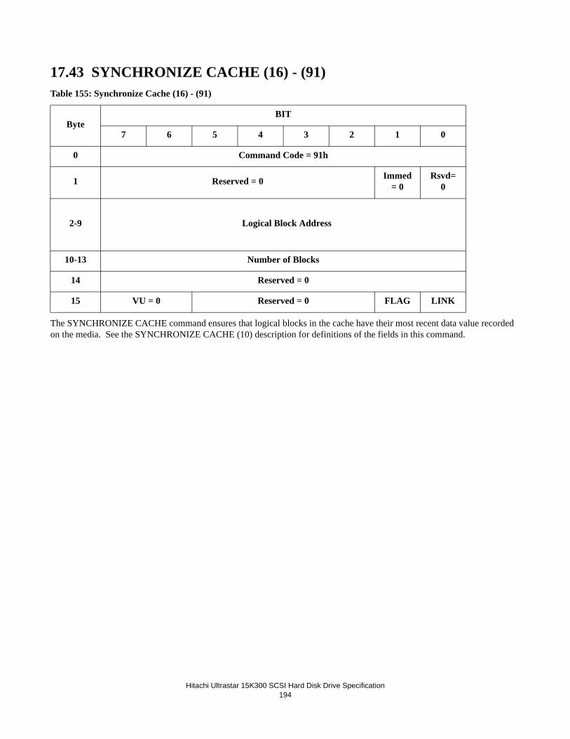
Hitachi Ultrastar 15K300 SCSI Hard Disk Drive Specification194
17.43 SYNCHRONIZE CACHE (16) - (91)Table 155: Synchronize Cache (16) - (91)
The SYNCHRONIZE CACHE command ensures that logical blocks in the cache have their most recent data value recorded on the media. See the SYNCHRONIZE CACHE (10) description for definitions of the fields in this command.
ByteBIT
7 6 5 4 3 2 1 0
0 Command Code = 91h
1 Reserved = 0 Immed = 0
Rsvd=0
2-9 Logical Block Address
10-13 Number of Blocks
14 Reserved = 0
15 VU = 0 Reserved = 0 FLAG LINK

Hitachi Ultrastar 15K300 SCSI Hard Disk Drive Specification195
17.44 TEST UNIT READY (00)Table 156: TEST UNIT READY (00)
The TEST UNIT READY command allows the Initiator to check if the drive is READY. The SCSI specification defines READY as the condition where the device will accept a media-access command without returning Check Condition status.
The drive will first verify that the motor is spinning at the correct speed. If the spindle motor is not spinning at the correct speed, Check Condition status is returned with sense key of Not Ready. If the motor is spinning at the correct speed, the drive accepts normal media access commands.
The TEST UNIT READY command is not intended as a diagnostic. No self diagnostic is performed by the device as a result of this command.
The TEST UNIT READY command has special significance for power sequencing using the UNIT START command with an Immediate bit of one. In this mode the UNIT START command returns Task Complete status before the completion of motor spin-up and expects the initiator to issue TEST UNIT READY commands to determine when the motor has reached the proper speed.
Note: The spindle automatically starts in automatic spin-up mode. The drive does not execute any commands other than TEST UNIT READY, INQUIRY, or REQUEST SENSE command until the Power On sequence is complete. The drive will return Check Condition status with Not Ready sense key and In Process of Becoming Ready sense code for all other com-mands during the Power On period.
ByteBit
7 6 5 4 3 2 1 0
0 Command Code = 00h
1 Reserved = 0 Reserved = 0
2-4 Reserved = 0
5 VU = 0 Reserved = 0 FLAG LINK

Hitachi Ultrastar 15K300 SCSI Hard Disk Drive Specification196
17.45 VERIFY (2F)Table 157: VERIFY (2F)
The VERIFY command requests that the drive verify the data written on the media. A verification length of zero indicates that no data will be transferred. This condition is not considered an error.
• ByteChk bit set to zero indicates that the data is read from the disk and verified using ECC.If an ECC error is detected in the verify process, Check Condition status is returned with sense key set to Medium Error. ByteChk bit set to one indicates that byte-by-byte comparison is performed between the data on the disk and data transferred from the initiator during the data-out phase.If the comparison is unsuccessful, the command is terminated with Check Condition status and the sense key is set to Miscompare.
• DPO (Disable Page Out) bit of one indicates that the data accessed by this command is to be assigned the lowest pri-ority for being written into or retained by the cache. A DPO bit of one overrides any retention priority specified in the Mode Select Page 8 Caching Parameters. A DPO bit of zero indicates the priority is determined by the retention pri-ority. The Initiator should set the DPO bit when the blocks read by this command are not likely to be read again in the near future.
If caching is enabled, the command performs an implied FUA and an implied Synchronize Cache before starting the VERIFY. This ensures that the medium, not the cache, is being verified.
The command stops on Check Condition and reports the LBA in error. The command must be reissued, starting with the next LBA, to verify the remainder of the Drive.
The Verification Length is the number of blocks to check.
The data (if any) from the data-out phase and the data from the media are not retained in the cache. Therefore, the DPO bit has no effect on this command and is ignored.
VRPROTECT defines the manner in which protection information read from disk shall be checked during processing of the command. Protection information is stored on disk, and may be validated using the drive's internal checking algorithms, and also byte-by-byte compared using data from the initiator when ByteChk=1.
ByteBIT
7 6 5 4 3 2 1 0
0 Command Code = 2Fh
1 VRPROTECT DPO Reserved = 0 ByteChk
RSVD = 0
2-5
(MSB)
Logical Block Address
(LSB)
6 Reserved = 0
7-8(MSB) Verification Length
(LSB)
9 VU = 0 Reserved = 0 FLAG LINK

Hitachi Ultrastar 15K300 SCSI Hard Disk Drive Specification197
If the drive is not formatted with protection information, VRPROTECT must be set to 000b, else Check Condition status will be returned with sense key of Illegal Request and additional sense code of Invalid Field in CDB.
VRPROTECT=000b
If the drive is not formatted with protection information, only user data is verified.
If the drive is formatted with protection information:
- Logical Block Guard is checked
- Logcial Block Application Tag is checked (applies to VERIFY(32) command only)
- Logical Block Reference Tag is checked
VRPROTECT=001b
- Logical Block Guard is checked
- Logcial Block Application Tag is checked (applies to VERIFY(32) command only)
- Logical Block Reference Tag is checked
VRPROTECT=010b
- Logical Block Guard is not checked
- Logcial Block Application Tag is checked (applies to VERIFY(32) command only)
- Logical Block Reference Tag is checked
VRPROTECT=011b
- Logical Block Guard is not checked
- Logcial Block Application Tag is not checked
- Logical Block Reference Tag is not checked
VRPROTECT=100b
- Logical Block Guard is checked
- Logcial Block Application Tag is not checked
- Logical Block Reference Tag is not checked
VRPROTECT=101b, 110b, 111b
These values are reserved. Check Condition status will be returned with sense key of Illegal Request and additional sense code of Invalid Field in CDB.
If a check of the protection information fails, Check Condition status will be returned with sense key of Aborted Command and additional sense code indicating which protection field check failed.
If ByteChk=1, the drive's internal checking of protection information is done only when VRPROTECT=000b and the drive is formatted with protection information

Hitachi Ultrastar 15K300 SCSI Hard Disk Drive Specification198
If ByteChk=1, and VRPROTECT is not set to 000b, checking of protection information is performed on the fields described above as a byte-by-byte comparison against the data transferred to the drive by the initiator during the Data Out phase..
Refer to the ANSI T10 standards for additional details of protection information.

Hitachi Ultrastar 15K300 SCSI Hard Disk Drive Specification199
17.46 VERIFY (12) - (AF)Table 158: Verify (12) - (AF)
The VERIFY(12) command causes the drive to verify data written on the media. See the VERIFY(10) description for the def-initions of the fields in this command.
ByteBIT
7 6 5 4 3 2 1 0
0 Command Code = AFh
1 VRPROTECT DPO FUA Reserved=0
ByteChk
Reserved = 0
2-5
(MSB)
Logical Block Address
(LSB)
6 - 9
(MSB)
Verification Length
(LSB)
10 Reserved = 0
11 VU = 0 Reserved = 0 FLAG LINK

Hitachi Ultrastar 15K300 SCSI Hard Disk Drive Specification200
17.47 VERIFY (16) - (8F)Table 159: Verify (16) - (8F)
The VERIFY command requests that the drive verify the data written on the media. See the VERIFY (10) description for the definitions of the fields in this command.
ByteBit
7 6 5 4 3 2 1 0
0 Command Code = 08Fh
1 VRPROTECT DPO Reserved = 0 Byte Chk
Rsvd = 0
2-9
(MSB)
Logical Block Address
(LSB)
10-13
(MSB)
Verification Length
(LSB)
14 Reserved = 0
15 VU = 0 Reserved = 0 FLAG LINK

Hitachi Ultrastar 15K300 SCSI Hard Disk Drive Specification201
17.48 WRITE (6) - (0A)Table 160: WRITE (6) - (0A)
The WRITE command requests the drive to write the specified number of blocks of data (Transfer Length) from the Initiator to the medium starting at the specified Logical Block Address (LBA).
See Section 17.15 “READ (6) - (08)” on page 148 for the parameters.
ByteBit
7 6 5 4 3 2 1 0
0 Command Code = 0Ah
1 Reserved = 0 (MSB) LBA
2-3 Logical Block Address
(LSB)
4 Transfer Length
5 VU = 0 Reserved = 0 FLAG LINK

Hitachi Ultrastar 15K300 SCSI Hard Disk Drive Specification202
17.49 WRITE (10) - (2A)Table 161: WRITE (10) - (2A)
The WRITE (10) command requests that the drive write the data transferred from the Initiator. This command is processed like the standard WRITE (6) - (0A) command except for the longer transfer length.
• Transfer Length is the number of contiguous blocks to be transferred. If the transfer length is zero, the seek occurs, but no data is transferred. This condition is not considered an error.
• DPO (Disable Page Out) bit of one indicates that the data accessed by this command is to be assigned the lowest pri-ority for being written into or retained by the cache. A DPO bit of one overrides any retention priority specified in the Mode Select Page 8 Caching Parameters. A DPO bit of zero indicates that the priority is determined by the retention priority. The Initiator should set the DPO bit when the blocks written by this command are not likely to be read in the near future.
• FUA (Force Unit Access) bit of one indicates that the Target must write the data to the media before returning Good status. A FUA bit of zero indicates that the Target may return Good status prior to writing the data to the media.
• FUA_NV (Force Unit Access Non-Volatile Cache) may be set to 0 or 1, but is ignored since NV_SUP=0 in Inquiry Page 86h.
If a WRITE(6) command is received after protection information is enabled, the drive will set the protection information as follows as it writes each block to disk:
• the Logical Block Guard field is set to a properly generated CRC• the Logical Block Reference Tag field is set to:• the least significant four bytes of the LBA, if the RTO_EN bit is set to zero in the READ CAPACITY (16)
parameter data ; or• FFFFFFFFh, if the RTO_EN bit is set to one;• the Logical Block Application Tag field is set to• FFFFh, if the ATO bit is set to one in Mode Page 0Ah• Any value, if the ATO bit is set to zero.
WRPROTECT defines the manner in which protection information written to disk shall be checked during processing of the command. Protection information may be transmitted to the drive with the user data, based on the WRPROTECT bit and the drive format.
Byte
Bit
7 6 5 4 3 2 1 0
0 Command Code = 2Ah
1 WRPROTECT DPO FUA Rsvd=0 FUA_NV
Obso-lete
2-5
(MSB)
Logical Block Address
(LSB)
6 Reserved = 0
7-8(MSB Transfer Length
(LSB)
9 VU = 0 Reserved = 0 FLAG LINK
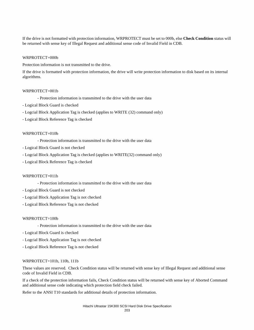
Hitachi Ultrastar 15K300 SCSI Hard Disk Drive Specification203
If the drive is not formatted with protection information, WRPROTECT must be set to 000b, else Check Condition status will be returned with sense key of Illegal Request and additional sense code of Invalid Field in CDB.
WRPROTECT=000b
Protection information is not transmitted to the drive.
If the drive is formatted with protection information, the drive will write protection information to disk based on its internal algorithms.
WRPROTECT=001b
- Protection information is transmitted to the drive with the user data
- Logical Block Guard is checked
- Logcial Block Application Tag is checked (applies to WRITE (32) command only)
- Logical Block Reference Tag is checked
WRPROTECT=010b
- Protection information is transmitted to the drive with the user data
- Logical Block Guard is not checked
- Logcial Block Application Tag is checked (applies to WRITE(32) command only)
- Logical Block Reference Tag is checked
WRPROTECT=011b
- Protection information is transmitted to the drive with the user data
- Logical Block Guard is not checked
- Logcial Block Application Tag is not checked
- Logical Block Reference Tag is not checked
WRPROTECT=100b
- Protection information is transmitted to the drive with the user data
- Logical Block Guard is checked
- Logcial Block Application Tag is not checked
- Logical Block Reference Tag is not checked
WRPROTECT=101b, 110b, 111b
These values are reserved. Check Condition status will be returned with sense key of Illegal Request and additional sense code of Invalid Field in CDB.
If a check of the protection information fails, Check Condition status will be returned with sense key of Aborted Command and additional sense code indicating which protection field check failed.
Refer to the ANSI T10 standards for additional details of protection information.

Hitachi Ultrastar 15K300 SCSI Hard Disk Drive Specification204

Hitachi Ultrastar 15K300 SCSI Hard Disk Drive Specification205
17.50 WRITE (12) - (AA)Table 162: Write (12) - (AA)
The WRITE(12) command causes the drive to write data from the initiator to the media. See the WRITE(10) description for the definitions of the fields in this command.
Byte
Bit
7 6 5 4 3 2 1 0
0 Command Code = AAh
1 WRPROTECT DPO FUA Rsvd=0 FUA_NV Rsvd=0
2-5
(MSB)
Logical Block Address
(LSB)
6-9
(MSB)
Transfer Length
(LSB)
10 Reserved=0
11 VU = 0 Reserved = 0 FLAG LINK
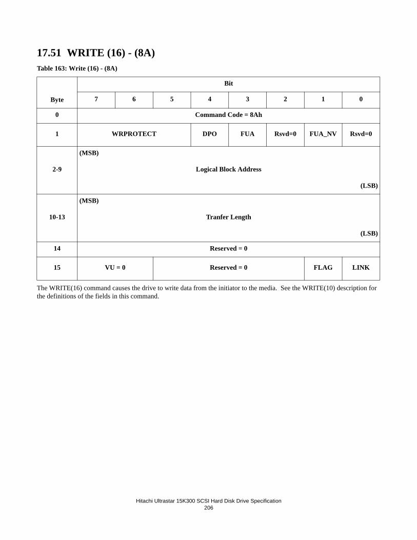
Hitachi Ultrastar 15K300 SCSI Hard Disk Drive Specification206
17.51 WRITE (16) - (8A)Table 163: Write (16) - (8A)
The WRITE(16) command causes the drive to write data from the initiator to the media. See the WRITE(10) description for the definitions of the fields in this command.
Byte
Bit
7 6 5 4 3 2 1 0
0 Command Code = 8Ah
1 WRPROTECT DPO FUA Rsvd=0 FUA_NV Rsvd=0
2-9
(MSB)
Logical Block Address
(LSB)
10-13
(MSB)
Tranfer Length
(LSB)
14 Reserved = 0
15 VU = 0 Reserved = 0 FLAG LINK

Hitachi Ultrastar 15K300 SCSI Hard Disk Drive Specification207
17.52 WRITE AND VERIFY (10) - (2E)Table 164: WRITE AND VERIFY (10) - (2E)
WRITE AND VERIFY command requests that the drive writes the data transferred from the Initiator to the medium and then verify that the data is correctly written. If caching is enabled, an implied FUA (Force Unit Access) and an implied Synchronize Cache are performed before starting the operation. This insures that data from the disk, not the cache, is verified.
• See the WRITE (10) command description for the definition of the WRPROTECT field. • Transfer Length is the number of contiguous blocks to to transferred. If the transfer length is zero, the seek occurs,
but no data is transferred. This condition is not considered an error.If caching is enabled, the command performs an implied FUA and an implied Synchronize Cache before starting the operation. This insures that the medium, not the cache, is being verified.
• ByteChk bit set to zero indicates that the data is read back from the disk and verified using ECC after the successful write operation. If an ECC error is detected in the verify process, Check Condition status is returned with sense key set to Medium Error. ByteChk bit set to one indicates that byte-by-byte comparison is performed between data on the disk starting the block specified in LBA field and data transferred from the Initiator.If the comparison is unsuccessful, the command is terminated with Check Condition status and the sense key is set to Miscompare.
• DPO (Disable Page Out) bit of one indicates that the data written by this command is to be assigned the lowest prior-ity for being written into or retained by the cache. A DPO bit of one overrides any retention priority specified in the Mode Select Page 8 Caching parameters. A DPO bit of zero indicates the priority is determined by the retention pri-ority.The Initiator should set the DPO bit when the blocks written by this command are not likely to be read again in the near future.
ByteBit
7 6 5 4 3 2 1 0
0 Command Code = 2Eh
1 WRPROTECT DPO Reserved = 0 ByteChk
Obso-lete
2-5
(MSB)
Logical Block Address
(LSB)
6 Reserved = 0
7-8(MSB) Transfer Length
(LSB)
9 VU = 0 Reserved = 0 FLAG LINK

Hitachi Ultrastar 15K300 SCSI Hard Disk Drive Specification208
17.53 WRITE AND VERIFY (12) - (AE)Table 165: Write andVerify (12) - (AE)
The WRITE AND VERIFY command requests that the drive write the data transferred from the Initiator to the medium and then verify that the data is correctly written. See the WRITE AND VERIFY (10) description for the definitions of the fields in this command.
ByteBit
7 6 5 4 3 2 1 0
0 Command Code = AEh
1 WRPROTECT DPO Reserved = 0 ByteChk Obsolete
2-5
(MSB)
Logical Block Address
(LSB)
6-9
(MSB)
Transfer Length
(LSB)
10 Reserved = 0
11 VU = 0 Reserved = 0 FLAG LINK

Hitachi Ultrastar 15K300 SCSI Hard Disk Drive Specification209
17.54 WRITE AND VERIFY (16) - (8E)Table 166: Write and Verify (16) - (8E)
The WRITE AND VERIFY command requests that the drive write the data transferred from the Initiator to the medium and then verify that the data is correctly written.
ByteBit
7 6 5 4 3 2 1 0
0 Command Code = 8Eh
1 WRPROTECT DPO Reserved = 0 ByteChk
Obso-lete
2-9
(MSB)
Logical Block Address
(LSB)
10-13(MSB) Transfer Length
(LSB)
14 Reserved = 0
15 VU = 0 Reserved = 0 FLAG LINK

Hitachi Ultrastar 15K300 SCSI Hard Disk Drive Specification210
17.55 WRITE BUFFER (3B)Table 167: WRITE BUFFER (3B)
The WRITE BUFFER command is used in conjunction with the READ BUFFER command as a diagnostic function for test-ing the memory of the drive and the SCSI bus integrity. This command does not alter the medium of the drive. Additional modes are provided for downloading microcode and saving microcode.
This command will cause the entire cache to be emptied.
The function of this command and the meaning of fields within the command descriptor block depend on the contents of the mode field.
MODE Description
00000 Write combined header and data
00010 Data
00100 Download Microcode
00101 Download Microcode and Save - single binary file
00111 Download Microcode and Save - multiple binary files
01010 Write Data to Echo Buffer
11010 Enable expander Communications Protocol
All Others Not Supported
If any values other than shown above are specified, Check Condition status is returned with a sense key of Illegal Request and additional sense code of Invalid Field in CDB.
17.55.1 Combined Header And Data (Mode 00000b)In this mode, the data to be transferred is preceded by a four-byte header.
Buffer ID must be zero. If another value is specified, no download function is performed and the command is terminated with Check Condition status. And the drive shall set the sense key to Illegal Request and additional sense code to Illegal Field in CDB.
ByteBit
7 6 5 4 3 2 1 0
0 Command Code = 3Bh
1 Reserved = 0 Mode
2 Buffer ID
3-5
(MSB)
Buffer Offset
(LSB)
6-8
(MSB)
Parameter List Length
(LSB)
9 VU = 0 Reserved = 0 FLAG LINK

Hitachi Ultrastar 15K300 SCSI Hard Disk Drive Specification211
Buffer Offset must be zero. If another value is specified, no download function is performed and the command is terminated with Check Condition status. And the drive shall set the sense key to Illegal Request and additional sense code to Illegal Field in CDB.
Parameter List Length specifies the number of bytes that shall be transferred during the DATA OUT phase. This number includes four bytes of header, so the data length to be stored in the drive buffer is transfer length minus four. If the length exceeds the buffer size, the command is terminated with Check Condition status. And the drive shall set sense key to Illegal Request and additional sense code to Illegal Field in CDB. A Parameter List Length of less than four (size of header) indicates no data is transferred.
The 4-byte header consists of all reserved bytes.
Table 168: Write Buffer Header
17.55.2 Write Data (Mode 00010b)In this mode, the DATA OUT phase contains buffer data.
Buffer ID must be zero. If another value is specified, no download function is performed and the command is terminated with Check Condition status. And the drive shall set the sense key to Illegal Request and additional sense code to Illegal Field In CDB.
Buffer Offset specifies the offset of the memory space specified by the Buffer ID. The initiator should conform to the offset boundary requirements returned in the READ BUFFER descriptor. If the value exceeds the buffer specified, the command is terminated with Check Condition status. And the drive shall set the sense key to Illegal Request and additional sense code to Illegal Field In CDB.
Parameter List Length specifies the Parameter List Length. It must be• less than the capacity of the buffer size after adding the Buffer Offset value and• on a sector boundary
A Parameter List Length of zero indicates no data is to be transferred and command status is returned.
If an invalid value is specified, the command is terminated with Check Condition status. And the drive shall set the sense key to Illegal Request and additional sense code to Illegal Field In CDB.
ByteBit
7 6 5 4 3 2 1 0
0-3 Reserved = 0

Hitachi Ultrastar 15K300 SCSI Hard Disk Drive Specification212
17.55.3 Download Microcode (Mode 00100b)NOTE: It is not expected that a customer will ever issue this format of the command.
In this mode, the microcode is transferred to the control memory space of the drive. When downloaded, the drive will operate with the newly downloaded code immediately until the next power cycle.
Buffer ID field is used to indicate which portion of the microcode image is being downloaded. The following Buffer IDs are supported by the Target:
- 00h: Main Microprocessor Code
- nnh : ID of Vendor Unique Reserved Area
Any unsupported value for the Buffer ID will cause the command to terminate with Check Condition status. And the drive shall set the sense key to Illegal Request and additional sense code to Illegal Field In CDB.
Buffer Offset must be zero. If an invalid value is specified, the command is terminated with Check Condition status. The drive shall set the sense key to Illegal Request and additional sense code to Illegal Field in CDB.
Parameter List Length must be the size of the data set to be downloaded. It may also be set to 0000h in which case no code is updated and command status is returned. If an invalid value is specified, the command is terminated with Check Condition status. And the drive shall set the sense key to Illegal Request and additional sense code to Illegal Field In CDB.
This process generates a unit attention condition for MICROCODE HAS BEEN CHANGED for all Initiators except the one which sent the WRITE BUFFER command. Upon the completion of the WRITE BUFFER command the new microcode is immediately ready for operation.
Note: The Download Microcode mode described in this specification is to indicate that the drive will accept a command with this mode, though it is not expected that a user will ever issue such a command. To use the write buffer command with this mode, a special microcode version is required from development. If such a microcode is released from development, then it will include appropriate instructions on the function of new microcode and its effect on the drive operations after download.
17.55.4 Download Microcode and Save (Mode 00101b) -Single Binary FileIn this mode the data is transferred to the drive to save into the System reserved area on the disk. This is for functional upgrade and configuration change reflecting the user's requirements and the manufacturer’s reason or both, and it is stored in the media as a permanent copy. The newly downloaded code becomes effective after the drive issues and completes a self-initiated Power On Reset.
Note: It requires up to 30 seconds to update the microcode including the Flash ROM update.
Note: New code to be downloaded to the drive will be provided by development either by request of a customer for an addi-tional function or as a result of a functional change by development. However please note that not all possible fixes or new functions can be applied to a drive in this manner and that there is a very high dependency on the level of ROM code contained within the drive. If an invalid code or a code not compatible with the ROM code is downloaded, the drive will usually reject this code and will continue normal operation. However there is a small possibility that an invalid code will be accepted. If this occurs, the unit usually becomes inoperable and will have to be returned to the manufacturer for recovery.
Buffer ID field is used to indicate which portion of the microcode image is being downloaded. To download microcode, the buffer ID should be set to 00h. Other values are reserved for Hitachi development purposes only.
17.55.5 Download Microcode and Save (Mode 00111b) - Multiple Binary FilesIn this mode the target receives a segment of the binary microcode file. The Parameter List Length (segment length) of each segment shall be a multiple of 4K bytes. The total length of all segments received shall be equal to the total length of the binary microcode file. All segments must be sent in the proper sequential order.All segments must be sent in the proper sequential order.

Hitachi Ultrastar 15K300 SCSI Hard Disk Drive Specification213
If an invalid Parameter List Length is specified, Check Condition status is returned with sense key of Illegal Request and additional sense code of Invalid Field in CDB.
The first segment sent in this mode indicates, by default, the first segment of the binary microcode file. If a Check Condition status is returned in this mode, a Buffer ID == 00h in the subsequent Write Buffer command in this mode indicates the first segment of the binary microcode file. Otherwise the Buffer ID field is ignored.
The Buffer Offset field is ignored.
After all segments of the binary microcode file have been received, the drive behavior is the same as Download Microcode and Save (Mode 00101b) - Single Binary File.
17.55.6 Write Data to Echo Buffer (Mode 01010b)In this mode the Target transfers data into the echo buffer. The echo buffer is assigned in the same manner by the Target as it would for a WRITE operation. Data will be sent aligned on 4-byte boundaries.
Upon successful completion of a WRITE BUFFER command the data will be preserved in the echo buffer unless there is an intervening command to any logical unit, in which case it may be changed.
17.55.7 Enable Expander Communications Protocol (Mode 11010b)In this mode the drive behavior is the same as Write Data to Echo Buffer (Mode 0101b).

Hitachi Ultrastar 15K300 SCSI Hard Disk Drive Specification214
17.56 WRITE LONG (3F)Table 169: WRITE LONG (3F)
The WRITE LONG command requests the drive to write one block of data transferred from the Initiator.
The transfer data must include• User Data• 56 bytes of ECC data
Parameters are• Logical Block Address field specifies the logical block at which the write operation shall occur.• Byte Transfer Length. This field must specify the exact number of bytes of data available for transfer. If a non-zero
byte transfer length does not match the available data length, the Target terminates the command with Check Condi-tion status, then the sense key is set to Illegal Request, and an additional sense code is set to Invalid Field in CDB. The valid and ILI bits are set to one and the information field is set to the difference of the requested length minus the actual length in bytes. Negative values are indicated by two's complement notation.
ByteBit
7 6 5 4 3 2 1 0
0 Command Code = 3Fh
1 Reserved = 0 Reserved = 0 Obso-lete
2-5
(MSB)
Logical Block Address
(LSB)
6 Reserved = 0
7-8(MSB) Byte Transfer Length
(LSB)
9 VU = 0 Reserved = 0 FLAG LINK

Hitachi Ultrastar 15K300 SCSI Hard Disk Drive Specification215
17.57 WRITE SAME (41)Table 170: WRITE SAME (41)
The WRITE SAME command instructs the Target to write a single block of data transferred to the Target from the Initiator to a number of sequential logical blocks. This command is useful for writing large data areas without sending all of the data over the SCSI bus.
• See the WRITE(10) command description for the definition of the WRPROTECT field.• Logical Block Address specifies the address at which the write begins. The Number of Blocks specifies the number
of contiguous blocks to be written. If the number is zero, all of the remaining blocks on the specified Logical Unit are written.
• Number of Blocks specifies the number of contiguous blocks to be written. If the number is zero, all of the remain-ing blocks on the specified logical unit are written.
• RelAdr (Relative Block Address) is not supported and must be set to be zero.
The data for this command is not retained in the cache.
ByteBit
7 6 5 4 3 2 1 0
0 Command Code = 41h
1 WRPROTECT Reserved = 0 PBDATA=0
LBDATA=0
Obso-lete
2-5
(MSB)
Logical Block Address
(LSB)
6 Reserved = 0
7-8(MSB) Number of Blocks
(LSB)
9 VU = 0 Reserved = 0 FLAG LINK

Hitachi Ultrastar 15K300 SCSI Hard Disk Drive Specification216
17.58 WRITE SAME (16) - (93)
The Write Same command instructs the Target to write a single block of data transferred to the Target from the Initiator to a number of sequential logical blocks. This command is useful for writing large data areas without sending all of the data over the SCSI bus. See the WRITE(10) command description for the definition of the WRPROTECT field.
Table 171: Write Same (16) - (93)
ByteBit
7 6 5 4 3 2 1 0
0 Command Code = 93h
1 WRPROTECT PBDATA=0
LBDATA=0 Obsolete
2-9
(MSB)
Logical Block Address
(LSB)
10-13
(MSB)
Number of Blocks
(LSB)
14 Reserved = 0
7-8(MSB) Number of Blocks
(LSB)
9 VU = 0 Reserved = 0 FLAG LINK
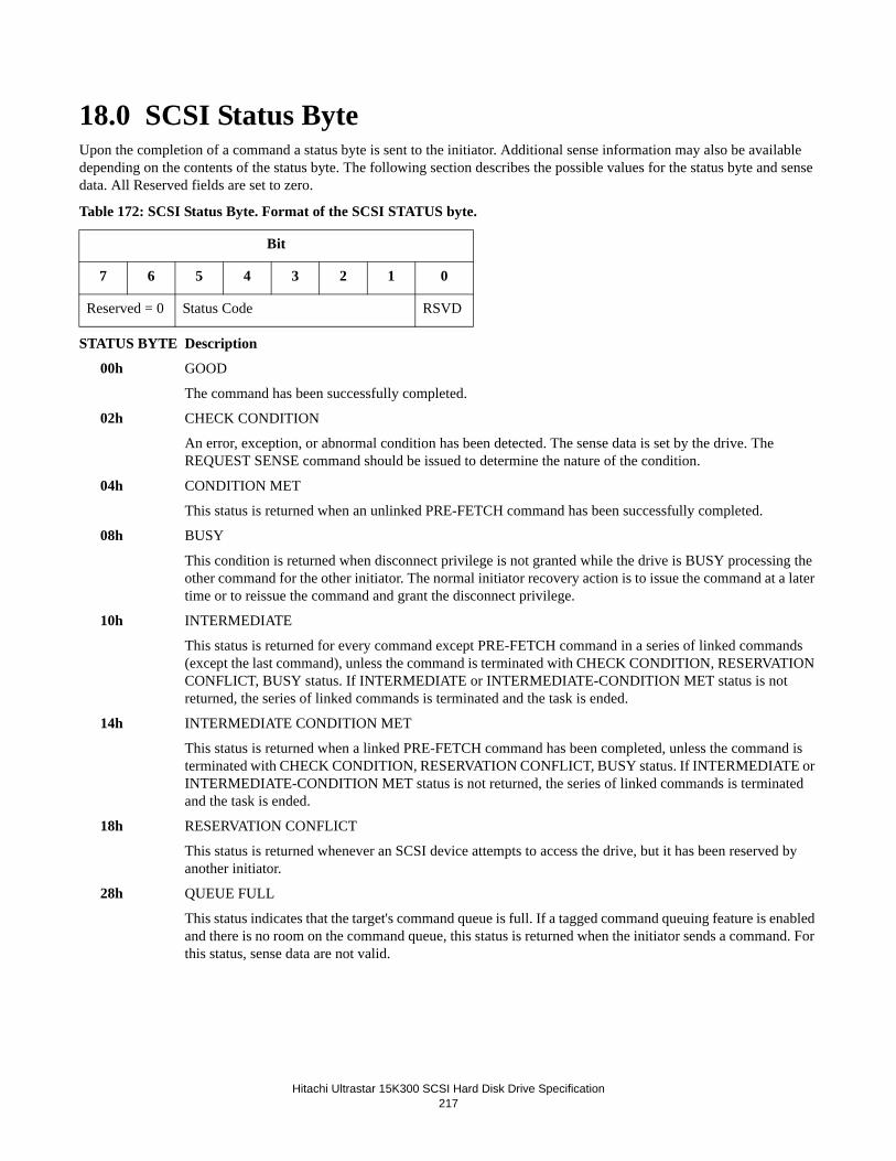
Hitachi Ultrastar 15K300 SCSI Hard Disk Drive Specification
217
18.0 SCSI Status ByteUpon the completion of a command a status byte is sent to the initiator. Additional sense information may also be available depending on the contents of the status byte. The following section describes the possible values for the status byte and sense data. All Reserved fields are set to zero.
Table 172: SCSI Status Byte. Format of the SCSI STATUS byte.
STATUS BYTE Description
00h GOOD
The command has been successfully completed.
02h CHECK CONDITION
An error, exception, or abnormal condition has been detected. The sense data is set by the drive. The REQUEST SENSE command should be issued to determine the nature of the condition.
04h CONDITION MET
This status is returned when an unlinked PRE-FETCH command has been successfully completed.
08h BUSY
This condition is returned when disconnect privilege is not granted while the drive is BUSY processing the other command for the other initiator. The normal initiator recovery action is to issue the command at a later time or to reissue the command and grant the disconnect privilege.
10h INTERMEDIATE
This status is returned for every command except PRE-FETCH command in a series of linked commands (except the last command), unless the command is terminated with CHECK CONDITION, RESERVATION CONFLICT, BUSY status. If INTERMEDIATE or INTERMEDIATE-CONDITION MET status is not returned, the series of linked commands is terminated and the task is ended.
14h INTERMEDIATE CONDITION MET
This status is returned when a linked PRE-FETCH command has been completed, unless the command is terminated with CHECK CONDITION, RESERVATION CONFLICT, BUSY status. If INTERMEDIATE or INTERMEDIATE-CONDITION MET status is not returned, the series of linked commands is terminated and the task is ended.
18h RESERVATION CONFLICT
This status is returned whenever an SCSI device attempts to access the drive, but it has been reserved by another initiator.
28h QUEUE FULL
This status indicates that the target's command queue is full. If a tagged command queuing feature is enabled and there is no room on the command queue, this status is returned when the initiator sends a command. For this status, sense data are not valid.
Bit
7 6 5 4 3 2 1 0
Reserved = 0 Status Code RSVD

Hitachi Ultrastar 15K300 SCSI Hard Disk Drive Specification218

Hitachi Ultrastar 15K300 SCSI Hard Disk Drive Specification
219
19.0 SCSI message systemThis chapter details how the message system is implemented on the drive. Included is a functional description of the supported messages.

Hitachi Ultrastar 15K300 SCSI Hard Disk Drive Specification220
19.1 Supported messagesThe messages supported by the drive are listed below:MESSAGE CODE(hex) Direction Negate ATN
Before last ACK
TASK COMPLETE 00 IN ---SYNCHRONOUS DATA TRANSFER REQUEST 01030 IN OUT YesWIDE DATA TRANSFER REQUEST* 010203 IN OUT YesPARALLEL PROTOCOL REQUEST 010604 IN OUT YesSAVE DATA POINTER 02 IN ---RESTORE POINTERS 03 IN ---DISCONNECT 04 IN ---INITIATOR DETECTED ERROR 05 OUT YesABORT TASK SET 06 OUT YesMESSAGE REJECT 07 IN OUT YesNO OPERATION 08 OUT YesMESSAGE PARITY ERROR 09 OUT YesLINKED TASK COMPLETE 0A IN ---LINKED TASK COMPLETE (w/FLAG) 0B IN ---TARGET RESET 0C OUT YesABORT TASK 0D OUT YesCLEAR TASK SET 0E OUT YesLOGICAL UNIT RESET 17 OUT YESSIMPLE 20XX IN OUT NoHEAD OF QUEUE 21XX OUT NoORDERED 22XX OUT NoIGNORE WIDE RESIDUE* 2301 IN ---IDENTIFY 80-FF IN ---IDENTIFY 80-FF OUT No
Key: IN = Target to Initiator, OUT = Initiator to TargetYES = Initiator shall negate ATN before last ACK of messageNO = Initiator may or may not negate ATN before last ACK of message--- = Not applicableXX = Queue Tag* = Wide SCSI Only
If an unsupported message is received, the drive will send the MESSAGE REJECT message to the Initiator. If at the time the unsupported message is received a valid NEXUS exists, the drive will continue with the command. If no valid NEXUS exists, the drive will go to Bus Free.
19.1.1 Task Complete (00)The drive sends this message to the Initiator to indicate that the execution of a command has been terminated and that valid status has been sent to the Initiator. After successfully sending this message the drive releases all bus signals and goes to BUS FREE phase.

Hitachi Ultrastar 15K300 SCSI Hard Disk Drive Specification
221
19.1.2 Synchronous Data Transfer Request (01, 03, 01h)Table 173: Synchronous Data Transfer Request.
A pair of Synchronous Data Transfer Request (SDTR) messages shown in Figure 159 are exchanged between an Initiator and a Target to establish the synchronous data transfer mode between the two devices. The message exchange establishes the per-missible transfer period and REQ/ACK offset for a synchronous data transfer between the two devices. The Initiator may ini-tiate a synchronous data transfer negotiation at any time after the LUN has been identified. A SDTR message exchange shall be initiated by a SCSI device whenever a previously arranged data transfer agreement may have become invalid. The agree-ment becomes invalid after any condition that may leave the data transfer agreement in an indeterminate state such as
1. after a Power-on Reset2. after a SCSI Bus “hard” reset condition3. after a Target Reset message
In addition a SCSI device may initiate a SDTR message exchange whenever it is appropriate to negotiate a new data transfer agreement (either synchronous or asynchronous).
M The transfer period (M) is the minimum time allowed between leading edges of successive REQ pulses and of succes-sive ACK pulses to meet the device requirements for successful reception of data. The drive supports trans-fer period in the range of 50 ns to 425 ns in increments of 25 ns. In addition to this, when the drive is working in LVD mode, it supports transfer period of 25 ns.
REQ/ACK Offset
X The ACK/REQ offset (X above) is the maximum number of REQ pulses allowed to be outstanding before the leading edge of its corresponding ACK pulses is received at the drive. A REQ/ACK offset value of zero indicates asynchro-nous data transfer mode. The drive supports REQ/ACK offset values in the range 0 through 63.
If ATN is negated before all bytes of a multiple-byte extended message is received, the drive will go to BUS FREE to signal a catastrophic error.
19.1.2.1 Synchronous Negotiation started by the InitiatorWhen the Target responds with REQ/ACK offset value of 0, the Initiator shall use asynchronous data transfer mode.
Byte Value Description
0 01H Extended message
1 03H Extended message length
2 01H SYNCHRONOUS DATA TRANSFER REQUEST code
3 M Transfer period (M times 4 nanoseconds)
4 X REQ/ACK offset
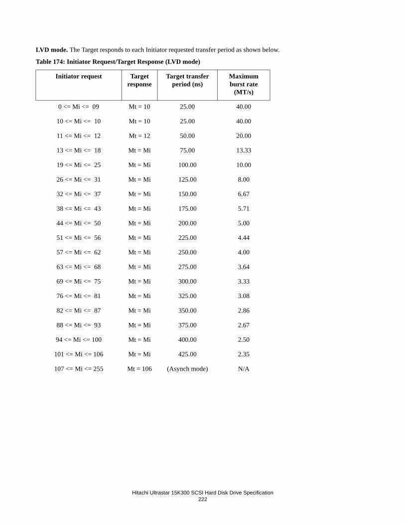
Hitachi Ultrastar 15K300 SCSI Hard Disk Drive Specification222
LVD mode. The Target responds to each Initiator requested transfer period as shown below.
Table 174: Initiator Request/Target Response (LVD mode)
Initiator request Target response
Target transfer period (ns)
Maximum burst rate
(MT/s)
0 <= Mi <= 09 Mt = 10 25.00 40.00
10 <= Mi <= 10 Mt = 10 25.00 40.00
11 <= Mi <= 12 Mt = 12 50.00 20.00
13 <= Mi <= 18 Mt = Mi 75.00 13.33
19 <= Mi <= 25 Mt = Mi 100.00 10.00
26 <= Mi <= 31 Mt = Mi 125.00 8.00
32 <= Mi <= 37 Mt = Mi 150.00 6.67
38 <= Mi <= 43 Mt = Mi 175.00 5.71
44 <= Mi <= 50 Mt = Mi 200.00 5.00
51 <= Mi <= 56 Mt = Mi 225.00 4.44
57 <= Mi <= 62 Mt = Mi 250.00 4.00
63 <= Mi <= 68 Mt = Mi 275.00 3.64
69 <= Mi <= 75 Mt = Mi 300.00 3.33
76 <= Mi <= 81 Mt = Mi 325.00 3.08
82 <= Mi <= 87 Mt = Mi 350.00 2.86
88 <= Mi <= 93 Mt = Mi 375.00 2.67
94 <= Mi <= 100 Mt = Mi 400.00 2.50
101 <= Mi <= 106 Mt = Mi 425.00 2.35
107 <= Mi <= 255 Mt = 106 (Asynch mode) N/A

Hitachi Ultrastar 15K300 SCSI Hard Disk Drive Specification
223
SE mode. The Target responds to each Initiator requested transfer period as shown below.
Table 175: Initiator Request/Target Response (SE mode)
Initiator request Target response
Target transfer period (ns)
Maximum burst rate
(MT/s)
0 <= Mi <= 11 Mt = 12 50.00 20.00
12 <= Mi <= 12 Mt = 12 50.00 20.00
13 <= Mi <= 18 Mt = Mi 75.00 13.33
19 <= Mi <= 25 Mt = Mi 100.00 10.00
26 <= Mi <= 31 Mt = Mi 125.00 8.00
32 <= Mi <= 37 Mt = Mi 150.00 6.67
38 <= Mi <= 43 Mt = Mi 175.00 5.71
44 <= Mi <= 50 Mt = Mi 200.00 5.00
51 <= Mi <= 56 Mt = Mi 225.00 4.44
57 <= Mi <= 62 Mt = Mi 250.00 4.00
63 <= Mi <= 68 Mt = Mi 275.00 3.64
69 <= Mi <= 75 Mt = Mi 300.00 3.33
76 <= Mi <= 81 Mt = Mi 325.00 3.08
82 <= Mi <= 87 Mt = Mi 350.00 2.86
88 <= Mi <= 93 Mt = Mi 375.00 2.67
94 <= Mi <= 100 Mt = Mi 400.00 2.50
101 <= Mi <= 106 Mt = Mi 425.00 2.35
107 <= Mi <= 255 Mt = 106 (Asynch mode) N/A

Hitachi Ultrastar 15K300 SCSI Hard Disk Drive Specification224
19.1.2.2 Synchronous Negotiation started by the TargetIf the drive recognizes that negotiation is required, and if the “Target Initiated SDTR” jumper is installed, the drive sends a SDTR message to the Initiator with minimum transfer period on the current receiver mode. The drive interprets the Initiator corresponding transfer period as shown in the figure below.
LVD mode
Table 176: Target response to Initiator's transfer period (LVD mode)
Initiator's requestTarget transfer Maximum burst rate
period (ns) (MT/s)
0 <= Mi <= 09 Send M+=10 to negotiate N/A
10 <= Mi <= 10 25 40.00
11 <= Mi <= 11 50 20.00
12 <= Mi <= 12 50 20.00
13 <= Mi <= 18 75 13.33
19 <= Mi <= 25 100 10.00
26 <= Mi <= 31 125 8.00
32 <= Mi <= 37 150 6.67
38 <= Mi <= 43 175 5.71
44 <= Mi <= 50 200 5.00
51 <= Mi <= 56 225 4.44
57 <= Mi <= 62 250 4.00
63 <= Mi <= 68 275 3.64
69 <= Mi <= 75 300 3.33
76 <= Mi <= 81 325 3.08
82 <= Mi <= 87 350 2.86
88 <= Mi <= 93 375 2.67
94 <= Mi <= 100 400 2.50
101 <= Mi <= 106 425 2.35
107 <= Mi <= 255 Send Message Reject (Asynch mode) N/A

Hitachi Ultrastar 15K300 SCSI Hard Disk Drive Specification
225
SE Mode
Table 177: Target response to Initiator's transfer period (SE mode)
19.1.3 Wide Data Transfer Request (01, 02, 03h)An Initiator and a Target exchange a pair of Wide Data Transfer Request messages to establish a data transfer width agreement between the two devices. The Initiator may initiate a wide data transfer negotiation at any time after the LUN has been identi-fied. The Target initiates a wide data transfer negotiation if the Target has not negotiated with the Initiator since the last time the Target was Reset (Power-on Reset, SCSI Bus Hard Reset, or Target Reset message).
Target initiated negotiation occurs either immediately following the Command phase or immediately following the first recon-nection. In either case negotiation occurs before any Data phase between the Target and the Initiator. The Target will negotiate the data transfer width agreement prior to negotiating the synchronous data transfer agreement. If a synchronous data transfer agreement is in effect when a Wide Data Transfer Request message is received, the Target will reset the synchronous agree-ment to asynchronous mode.
The implied data transfer width agreement remains in effect until the Target is Reset (Power-on Reset, SCSI Bus Hard Reset, or Target Reset message) or a new data transfer width agreement is negotiated. If a Reset occurs, the Target goes to eight bit mode.
Initiator's request Target transfer period (ns)
Maximum burst rate (MT/s)
0 <= Mi <= 11 M+=12 to negotiate N/A
12 <= Mi <= 12 50.00 20.00
13 <= Mi <= 18 75.00 13.33
19 <= Mi <= 25 100.00 10.00
26 <= Mi <= 31 125.00 8.00
32 <= Mi <= 37 150.00 6.67
38 <= Mi <= 43 175.00 5.71
44 <= Mi <= 50 200.00 5.00
51 <= Mi <= 56 225.00 4.44
57 <= Mi <= 62 250.00 4.00
63 <= Mi <= 68 275.00 3.64
69 <= Mi <= 75 300.00 3.33
76 <= Mi <= 81 325.00 3.08
82 <= Mi <= 87 350.00 2.86
88 <= Mi <= 93 375.00 2.67
94 <= Mi <= 100 400.00 2.50
101 <= Mi <= 106 425.00 2.35
107 <= Mi <= 255 Send Message Reject (Asynch mode) N/A

Hitachi Ultrastar 15K300 SCSI Hard Disk Drive Specification226
Table 178: Wide Data Transfer Request
E The Transfer Width Exponent (E) is two to the transfer width exponent bytes wide. Valid data transfer widths are 8 bits (E = 00h) and 16 bits (E = 01h). Value of E greater than 01h are reserved.
19.1.3.1 Transfer Width Negotiation started by the InitiatorIf the Initiator recognizes that negotiation is required and sends a Wide Data Transfer Request message out, the Target responds by changing to the Message In phase and sending a Wide Data Transfer Request message in to the Initiator prior to transferring any additional message bytes (or any other Information phase bytes) from the Initiator. This provides an interlock during the data transfer width negotiation.
The drive responds to each Initiator requested transfer width exponent as shown in the following table.
Table 179: Initiator request/Target response
If after the Target's response above the Initiator asserts the ATN signal and the first message received is either a Message Parity Error or a Message Reject message, the Target negates the data transfer width agreement and goes to 8 bits mode. For the Mes-sage Parity Error case the implied data transfer width agreement is reinstated if the Target successfully retransmits the Wide Data Transfer Request message to the Initiator. For any other message the Target completes negotiation and goes to the negoti-ated data transfer width.
19.1.3.2 Transfer Width Negotiation started by the TargetIf the Target recognizes that negotiation is required, the Target sends a Wide Data Transfer Request message to the Initiator with the transfer width exponent equal to 1 (E = 01h). The Initiator must respond by asserting the ATN signal prior to its release of ACK for the REQ/ACK handshake of the last byte of the Wide Data Transfer Request message. This provides an interlock during the wide data transfer negotiation. If the Initiator does not assert the ATN signal, the Target goes to 8 bit mode. If the Initiator does assert the ATN signal, the Target changes to the Message Out phase and receives a message from the Initiator.
If the first message received is a Wide Data Transfer Request message, the Target establishes the new data transfer mode. The
Byte Value Description
0 01H Extended message
1 02H Extended message length
2 03H WIDE DATA TRANSFER REQUEST code
3 E Transfer width exponent
Initiator's request
Target’sresponse
Target Data Transfer Width
Ei = 00h Et = 00h 8 Bit Data Transfers
Ei > 00h Et = 01h 16 Bit Data Transfers

Hitachi Ultrastar 15K300 SCSI Hard Disk Drive Specification
227
drive interprets the Initiator corresponding transfer width exponent as shown in the following table.
Table 180: Target request to Initiator
Note: If the corresponding transfer width exponent received from the Initiator indicates a data transfer width that is greater than 16 bits (E > 01h), the Target sends a Message Reject message to the Initiator to indicate 8-bit data transfer mode.
If the first message received from the Initiator is either a Message Parity Error or a Message Reject message, the Target goes to 8-bit data transfer mode. In the case of a Message Parity Error, the wide data transfer negotiation is restarted if the Target suc-cessfully retransmits the Wide Data Transfer Request message to the Initiator.
If the first message received from the Initiator is any other message, the Target goes to 8-bit data transfer mode. The Target assumes that the Initiator does not support wide data transfer and does not attempt to renegotiate with this Initiator.
The Target does not consider the implied agreement for wide data transfer operation to exist until the Target leaves the Mes-sage Out phase, implying that no parity error was detected. If the Target detects a parity error while attempting to receive the message from the Initiator, the Target goes to 8-bit data transfer mode. The Target will attempt to resume the wide data transfer negotiation by retrying the Message Out phase.
Note: If during the Message In phase of negotiations, either Target or Initiator started, ATN is asserted prior to transmission of the last byte of the message and the message is not Message Parity or Message Reject, the Target goes to 8-bit data transfer mode.
19.1.4 Parallel Protocol Request (01, 06, 04h)Parallel Protocol Request messages are used to negotiate a synchronous data transfer agreement and a wide data transfer agree-ment and to set the protocol options between two SCSI devices.
Table 181: Parallel Protocol Request
PARALLEL PROTOCOL REQUEST messages are used to negotiate a synchronous data transfer agreement and a wide data
Initiator request Target Data Transfer Width
Ei = 00h 8 bit data transfers
Ei = 01h 16 bit data transfers
Ei > 01h Send Message Reject (8 bit data transfer)
Byte Bit
7 6 5 4 3 2 1 0
0 Extended Message = 01h
1 Extended Message Length = 06h
2 Parallel Protocol Request = 04h
3 Transfer Period Factor
4 Reserved = 00h
5 REQ/ACK Offset
6 Transfer Width Exponent
7 PCOMP_EN RTI RD_STRM WR_FLOW HOLD_MCS QAS_REQ DT_REQ IU_REQ

Hitachi Ultrastar 15K300 SCSI Hard Disk Drive Specification228
transfer agreement and to set the protocol options between the initiator and the drive.
• Transfer Period Factor selects the transfer period and determines the timing values for the trans-fer rate. When both DT_REQ and IU_REQ are set to one, the following values are used. For the values larger than 9 is received from the initiator when both DT_REQ and IU_REQ are set to one, the drive responds with these bits set to zero.
Table 182: Initiator Request/Target Response (DT_REQ = 1, IU_REQ = 1)
If DT_REQ is set one and IU_REQ is set to zero, the following values are used.
Table 183: Initiator Request/Target Response (DT_REQ = 1, IU_REQ = 0)
If both DT_REQ and IU_REQ is set to zero, the following values are used
Table 184: Initiator Request/Target Response (DT_REQ = 0, IU_REQ = 0)
• REQ/ACK Offset determines the maximum number of REQs allowed to be outstanding before a corresponding ACK is received at the drive during synchronous or paced transfers. - The REQ/ACK Offset value is chosen to prevent overflow conditions in the reception buffer and offset
counter of the drive. The drive supports maximum offset of 127 (7Fh). A REQ/ACK Offset value of zero indicates asynchronous data transfer mode and that the Transfer Period Factor and the protocol options bits except QAS_REQ will be ignored.
• Transfer Wide Exponent defines the transfer width to be used during DATA IN and DATA OUT phases. If any of the protocol options bits other than QAS_REQ are set to one, then only wide transfer agreements are valid. The following values are supported.
Initiator Request Target Response
Target Transfer
Transfer Rate
0 <= Mi <= 8 Mt = 08h 6.25 nSec Fast-160
9 <= Mi <= 9 Mt = 09h 12.5 nSec Fast-80
Initiator Request Target Response
Target Transfer
Transfer Rate
0 <= Mi <= 9 Mt = 09h 12.5 nSec Fast-80
10 <= Mi <= 10 Mt = 0Ah 25 nSec Fast-40
11 <= Mi <= 12 Mt = 0Ch 50 nSec Fast-20
13 <= Mi <= 25 Mt = 19h 100 nSec Fast-10
26 <= Mi <= 255 Mt = 19h (Asynch Mode) Asynch
Initiator Request Target Response
Target Transfer
Transfer Rate
0 <= Mi <= 10 Mt = 0Ah 25 nSec Fast-40
11 <= Mi <= 12 Mt = 0Ch 50 nSec Fast-20
13 <= Mi <= 25 Mt = 19h 100 nSec Fast-10
26 <= Mi <= 50 Mt = 32h 200 nSec Fast-5
51 <= Mi <= 255 Mt = 32h (Asynch Mode) Asynch

Hitachi Ultrastar 15K300 SCSI Hard Disk Drive Specification
229
- 00h: 8 bit data bus (Narrow transfer agreement).- 01h: 16 bit data bus (Wide transfer agreement).
• PCOMP_EN (Precompensation Enable) is used to negotiate if the pre-compensation is enabled on all signals transmitted during DT DATA phases. The drive supports PCOMP_EN.
• RTI (Retain Training Information) is used to negotiate if the saving of paced data transfer training information is made so that the retraining is not necessary on each connection. The drive support RTI.
• RD_STRM (Read Streaming and Read Flow Control Enable) is used to negotiate if read stream-ing and read flow control are enabled. The drive supports RD_STRM.
• WR_FLOW (Write Flow Control Enable) is used to negotiate if write flow control is enabled during write streaming. The drive supports WR_FLOW.
• HOLD_MCS (Hold Margin Control Settings) is used to negotiate if any margin control settings which has been set with the margin control subpage of the port control mode page is retained.
• QAS_REQ (Quick Arbitration and Selection Enable Request) is used to negotiate if QAS is enabled. The drive supports QAS when IU_REQ is negotiated to be effective.
• DT_REQ (DT Clocking Enable Request) is used to negotiate if DT DATA phase is enabled. The drive supports DT_REQ.
• IU_REQ (Information Unit Enable Request) is used to negotiate if information unit transfer is enabled. The drive supports IU_REQ.
Table 185: Bit position table for Byte 7 of Parallel Protocol Request
QAS_REQ (Quick Arbitrate and Select) is not supported. The bit should be zero.
DT_REQ A bit of zero for DT_REQ (Double Transition Enable Request) indicates that DT DATA phases are to be disabled when received from the originating SCSI device and that DT DATA phases are not supported when received from the respond-ing SCSI device.
A DT_REQ bit of one indicates that DT DATA phases are to be enabled when received from the originating SCSI device and that DT DATA phases are supported when received from the responding SCSI device.
IU_REQ (Information Unit Request) is not supported. The bit should be 0.
19.1.5 Save Data Pointer (02)This message is sent from the drive to direct the Initiator to copy the active data pointer to the saved data pointer. The SAVE DATA POINTER message is only sent if the Initiator has previously indicated the ability to accommodate disconnection and reconnection via the IDENTIFY message.
The drive will send the SAVE DATA POINTER message to the Initiator prior to sending a DISCONNECT message to the Ini-tiator if a data phase has occurred and another data phase is required to successfully complete the command.
19.1.6 Restore Pointers (03)This message is sent from the drive to direct an Initiator to copy the most recently saved pointers to the corresponding com-mand, data, and status pointers. Command and status pointers should be restored to the beginning of the present command and status areas. The data pointer should be restored to the value at the beginning of the data area in the absence of a SAVE DATA POINTER message or to the value at the point at which the last SAVE DATA POINTER message occurred. Refer to Section
Bit
7 6 5 4 3 2 1 0
Reserved QAS_REQ DT_REQ IU_REQ

Hitachi Ultrastar 15K300 SCSI Hard Disk Drive Specification230
19.4, “SCSI Bus Related Error Handling protocol” on page 244.
19.1.7 Disconnect (04)This message is sent from the drive to inform an Initiator that the present connection is going to be broken. A later reconnect will be required in order to complete the current command. The disconnection serves to free the SCSI bus while the drive per-forms a relatively long operation that does not require the bus. These messages are sent only if the Initiator previously indi-cated (via the IDENTIFY message) the ability to accommodate disconnection and reconnection.
The DISCONNECT message may also be sent from the Initiator to the drive to disconnect from the SCSI bus. The drive does not support the DISCONNECT message from the Initiator. And it always responds by sending MESSAGE REJECT message to the Initiator.
19.1.8 Initiator Detected Error (05)This message is sent from an Initiator to inform the drive that an error has been detected that does not preclude the drive from retrying the previous COMMAND, DATA, and STATUS phase. The source of the error may be either related to previous activ-ities on the SCSI bus or may be internal to the Initiator and unrelated to any previous SCSI bus activity.
If the Initiator intends to send this message, the Initiator must assert the ATN signal prior to its release of ACK for the last byte transferred in the information phase that is to be retried. This provides an interlock so the drive can determine which informa-tion phase to retry.
After receiving this message the drive may retry the previous phase by sending a RESTORE POINTERS message to the Initi-ator and then repeating the previous COMMAND, DATA, or STATUS phase.
After receiving this message the drive may retry the MESSAGE IN phase by switching to the MESSAGE IN phase with asserting REQ and repeating the previous MESSAGE IN phase.
19.1.9 Abort Task Set (06)This message is sent from the Initiator to direct the drive to clear the present operation for this Initiator and logical unit includ-ing queued command(s). If a logical unit has been identified, then all pending data and status for the issuing Initiator and this logical unit will be cleared and the drive will go to the BUS FREE phase. Pending data and status for other logical unit and Ini-tiators will not be cleared. If a logical unit has not been identified, the drive will go to the BUS FREE phase without affecting an operation on any logical unit for this or any other Initiator. In either case no status or ending message will be sent to the Ini-tiator for this operation. It is not an error to send the ABORT message to a logical unit that is not currently performing an oper-ation for the Initiator.
Note: It is permissible for an Initiator to select the drive/LUN after the drive has disconnected from the Initiator for the pur-pose of sending an IDENTIFY message followed by an ABORT message. This will abort the command on the specified logi-cal unit.
19.1.10 Message Reject (07)This message is sent from either the Initiator or the drive to indicate that the last message received was inappropriate or has not been implemented.
If the Initiator intends to send this message, the Initiator must assert the ATN signal prior to its release of ACK for the REQ/ACK handshake of the message byte that is to be rejected. This provides an interlock so the drive can determine which mes-sage is rejected.
If the drive intends to send this message, the drive will change to the MESSAGE IN phase and send the MESSAGE REJECT message to the Initiator prior to transferring any additional message bytes (or any other information phase bytes) from the Ini-tiator regardless of ATN signal. This provides an interlock so the Initiator can determine which message is rejected. After the drive sends a MESSAGE REJECT message and if ATN signal is still asserted, it shall return to the MESSAGE OUT phase. The subsequent MESSAGE OUT phase shall begin with the first byte of a message
19.1.11 No Operation (08)This message is sent from the Initiator to the drive when the Initiator does not currently have any other valid message to send.
Hitachi Ultrastar 15K300 SCSI Hard Disk Drive Specification
231
This message is ignored by the drive and will not affect any operation.
19.1.12 Message Parity Error (09)This message is sent from the Initiator to inform the drive that the last message byte received had a parity error.
If the Initiator intends to send this message, the Initiator must assert the ATN signal prior to its release of ACK for the REQ/ACK handshake of the message byte that has the parity error. This provides an interlock so the drive can determine which mes-sage byte has the parity error.
If the drive receives this message under any other circumstance, the drive will change to BUS FREE to signal a catastrophic error. After receiving this message, the drive will retry sending the previous message to the Initiator.
19.1.13 Linked Task Complete (0A)The drive sends this message to the Initiator to indicate that execution of a linked command (with flag bit equal to zero) has completed and that valid status has been sent to the Initiator. After successfully sending this message, the drive goes to COM-MAND phase to receive the next command.
19.1.14 Linked Task Complete With Flag (0B)The drive sends this message to the Initiator to indicate that the execution of a linked command with flag bit set to one has completed and that valid status has been sent to the Initiator. After successfully sending this message, the drive goes to COM-MAND phase to receive the next command.
19.1.15 Target Reset (0C)This message is sent from an Initiator to direct the drive to clear all current commands. This message forces a hard reset condi-tion, which will reset the drive to an initial state with no operations pending for any Initiator. After receiving this message the drive will go to the BUS FREE phase.
19.1.16 Abort Task (0D)When the Target successfully receives this message, it clears the current I/O process and goes to Bus Free. If the Target has already started execution of an I/O process, the execution will be halted.
Pending status, data, and commands for other active or queued I/O processes shall not be affected.
19.1.17 Clear Task Set (0E)All I/O processes for all Initiators shall be cleared. All active I/O processes shall be terminated. The Target shall go to the Bus Free phase following successful receipt of this message.
19.1.18 Logical Unit Reset (17)This message is sent from an Initiator to direct the drive to clear all current commands and enter an initialized state with no operations pending for any Initiator. This message forces a reset similar to the Target Reset message, with the exception that initiator negotiated parameters (like interfaces speed and related options) are not reset, but are preserved.

Hitachi Ultrastar 15K300 SCSI Hard Disk Drive Specification232
19.1.19 Queue Tag messages (20H, 21H, 22H)Table 186: Queue Tag messages
Queue Tag messages are used to specify an identifier called a Queue Tag for an I/O process that establishes the I_T_L_Q nexus. The queue tag field is an 8-bit unsigned integer assigned by the Initiator during an initial connection. The Queue Tag for every I/O process for each I_T_L nexus must be unique. If the Target receives a Queue Tag that is currently in use for the I_T_L nexus, it will respond as “Incorrect Initiator Response”. A Queue Tag becomes available for reassignment when the I/O process ends. The numeric value of a Queue Tag has no effect on the order of execution.
Whenever an Initiator connects to the Target, the appropriate Queue Tag message must be sent immediately following the Identify message and within the same MESSAGE OUT phase to establish the I_T_L_Q nexus for the I/O process.
Whenever the Target reconnects to an Initiator to continue a tagged I/O process, the Simple message is sent immediately fol-lowing the Identify and within the same MESSAGE IN phase to revive the I_T_L_Q nexus for the I/O process.
19.1.19.1 Simple (20h)The Simple message specifies that the current I/O process be placed in the command queue. The order of execution with respect to other I/O processes received with Simple messages is up to the discretion of the Target. The Target will send Simple messages after reselection for I/O processes that were received with either Simple, Ordered, or Head of Queue messages.
19.1.19.2 Head Of Queue (21h)Commands with this tag should be inserted into the head of the queue. When a command is being executed, this tagged com-mand will be inserted to the head of queue to be executed after the command being currently executed. The previous executed command will not be terminated by this tagged command. This tagged command will wait until the previous command is com-pleted. If plural head-of-queue tagged commands are received, those command will be executed in LIFO (Last in First out) order. This will be ignored if the WCE bit is set.
19.1.19.3 Ordered (22h)This tagged command is executed in the order received. All commands received before this command should be executed before this command and all commands received after this commands should be executed after this command.
19.1.20 Ignore Wide ResidueTable 187: Ignore Wide Residue message format
The Ignore Wide Residue message is sent from the Target to indicate that the number of valid bytes sent during the last REQ/ACK handshake of a DATA IN phase is less than the negotiated transfer width. The ignore field (always = 01h) indicates that one byte (data bits 8-15) should be ignored. This message is sent immediately after the DATA IN phase and prior to any other
Byte Value Description
0 20H Simple Queue
21H Head of Queue
22H Ordered
1 XXh Queue Tag
Byte Value Description
0 23H Ignore Wide Residue message
1 01H Ignore

Hitachi Ultrastar 15K300 SCSI Hard Disk Drive Specification
233
messages. Even though a byte is invalid, its corresponding parity bit is valid for the value transferred.
19.1.21 Identify (80 - FF)This message is set by either the Initiator or the drive to establish the logical path connection between the two devices.
The IDENTIFY message is defined as follows:
Bit 7 This bit is always set to one to distinguish the IDENTIFY message from other messages.
Bit 6 This bit is only set to one by the Initiator to grant the drive the privilege of disconnecting. If this bit is zero, the drive will not disconnect unless the Initiator instructs the drive to disconnect by sending a DISCON-NECT message to the drive. This bit is set to zero when the drive sends an IDENTIFY message to the Initi-ator.
Bits 5-0 These bits specify the logical unit number (LUN).
Only one LUN may be identified for any one selection sequence. If the drive receives an IDENTIFY message with a new LUN after the LUN had previously been identified, the drive will go to the BUS FREE phase to signal a catastrophic error. The Ini-tiator may send more than one Identify message during a selection sequence in order to toggle disconnect/reconnect permis-sion if the specified LUN remains the same.
When the IDENTIFY message is sent from the drive to the Initiator during reconnection, an implied RESTORE POINTERS message must be performed by the Initiator.

Hitachi Ultrastar 15K300 SCSI Hard Disk Drive Specification234
19.2 Supported message functionsThe implementation of the supported messages will also include the following functions.
• Retry SCSI Command or STATUS phaseThe retry will be caused by the following error condition.
- The drive detected SCSI bus parity error (Command phase)
- The drive receives INITIATOR DETECTED ERROR MESSAGE during or at the conclusion of an information transfer phase (Command Data Out or Status Phase)
Note: The Initiator may send the INITIATOR DETECTED ERROR message as a result of an Initiator detected SCSI Bus parity error or an internal error.
• Retry MESSAGE IN phase
- The retry will be caused by the receipt of a MESSAGE PARITY ERROR message immediately following a MES-SAGE IN phase.
Note: The Initiator may send the MESSAGE PARITY ERROR message as a result of an Initiator detected SCSI Bus parity error during the Message In phase.
• Receipt of multiple Identify messages
- The Initiator is allowed to send multiple IDENTIFY messages out in order to toggle the disconnect/reconnect per-mission bit. This may be used to selectively enable or disable disconnect/reconnect permission during portions of a command. Note that this function does not affect the operation of the Forced Disconnect function.
• MESSAGE REJECT during Target Disconnection
- If the Initiator rejects the SAVE DATA POINTER message, the drive will disable disconnect/reconnect permission. This is equivalent to receiving an IDENTIFY message with bit 6 equal to zero. This will cause the drive to inhibit the pending disconnection.
- If the Initiator rejects the DISCONNECT message, the drive will not disconnect but may attempt to disconnect at a later time. This function may be used to selectively disable disconnection during portions of a command.

Hitachi Ultrastar 15K300 SCSI Hard Disk Drive Specification
235
19.3 Attention conditionThe attention condition allows an Initiator to inform the drive that a MESSAGE OUT phase is desired. The Initiator may cre-ate the attention condition by asserting the ATN signal at any time except during the ARBITRATION or BUS FREE phases.
The Initiator must create the attention condition by asserting the ATN signal at least two deskew delays before releasing ACK for the last byte transferred in a bus phase to guarantee that the attention condition will be honored before transition to a new bus phase. This will guarantee a predictable drive response to a message received during the MESSAGE OUT phase for this attention condition. If the ATN signal is asserted later, it may be honored in the current bus phase or the next bus phase and then may not result in the expected action.
After the Initiator asserts the ATN signal, the drive will respond with the MESSAGE OUT phase as follows:
Current phase Response
COMMAND MESSAGE OUT phase will occur after part or all of the Command Descriptor Block has been transferred to the drive. The Initiator must continue REQ/ACK handshakes during the COMMAND phase until the drive enters the MESSAGE OUT phase.
DATA The Message Out phase will occur after part or all of the data bytes have been transferred and not necessarily on a logical block boundary. The Initiator must continue REQ/ACK handshakes (asynchronous transfer) until it detects the phase change.
Note: In synchronous transfer the Initiator must continue sending ACK pulses to reach an offset of zero.
STATUS The Message Out phase will occur after the REQ/ACK handshake of the status byte has been completed.
MESSAGE IN The Message Out phase will occur before the drive sends another message.
SELECTION If ATN occurs during a Selection phase and before the Initiator releases the BSY signal, the Message Out phase will occur immediately after that Selection phase.
RESELECTIONThe MESSAGE OUT phase will occur after the drive has sent its IDENTIFY message for that RESELEC-TION phase. (The drive first tries to complete the reselection.)
The Initiator must keep the ATN signal asserted if more than one message byte is to be transferred during the MESSAGE Out phase. The drive will process each message byte (multiple bytes for an extended message) prior to receiving the next message from the Initiator. The drive will continue to handshake and process byte(s) in the MESSAGE OUT phase until ATN goes false unless one of the following conditions occurs:
1. The drive receives an illegal or inappropriate message and goes to the MESSAGE IN phase to send a MESSAGE REJECT message.
2. The drive detects a catastrophic error condition and goes to the BUS FREE phase.

Hitachi Ultrastar 15K300 SCSI Hard Disk Drive Specification236

Hitachi Ultrastar 15K300 SCSI Hard Disk Drive Specification237
20.0 Additional informationThis chapter provides additional information or descriptions of various functions, features, or operating models supported by the Target that are not fully described in previous chapters.
20.1 SCSI ProtocolThere are various operating conditions that prevent the Target from executing a SCSI command. This section describes each of these operating conditions and their relative priority.
20.1.1 Priority of SCSI Status Byte ReportingAfter establishing the I_T_L nexus or I_T_L_Q nexus the Target must first determine whether command execution is allowed. Execution is deferred until a later time if the command must be added to the command queue. Execution may also be pre-vented by an internal Target condition that requires the reporting of a Check Condition, Queue Full, Busy, or Reservation Con-flict Status. There are several different internal conditions to be active at the same time. The order in which the Target checks for each of these conditions determines their priority (highest priority first) as follows:
1. Check Condition status for invalid Logical Unit Number. (See Section 20.1.2, “Invalid LUN in Identify Message” on page 259)
2. Check Condition status for Incorrect Initiator Connection (See Section20.1.3, “Incorrect Initiator Connection” on page 238)
3. Check Condition status for Unit Attention Condition (See Section 20.1.5, “Unit Attention Condition” on page 2404. Busy Status or Queue Full Status (See 20.1.4, “Command Processing During Execution of Active I/O Process” on
page 2385. Check Condition status for Deferred Error Condition (See Section 20.1.8, “Deferred Error Condition” on page 241)6. Check Condition status during Startup and Format operations (See Section “20.1.6, “Command processing during star-
tup and format operations” on page 241)7. Reservation Conflict status (See Section 20.1.10, “Command Processing while Reserved” on page 249)8. Check Condition status for invalid command opcode9. Check Condition status for invalid command descriptor block
The highest priority internal condition that prevents command execution is reported by the Target provided there is no bus error.
For all Check Conditions Sense data is built by the target provided a valid LUN address is known. Sense data is cleared by the Target upon receipt of any subsequent command to the LUN from the initiator receiving the Check Condition.
20.1.2 Invalid LUN in Identify MessageThere are three different circumstances defined within the SCSI protocol when the response to an invalid LUN will occur. Each of these result in a different response.
20.1.2.1 Case 1 - Selection message sequence with Inquiry commandThe INQUIRY command is a special case in SCSI. It is used to configure the bus when the drive ID's and LUN's are not known. The proper response is to return the inquiry data with a peripheral drive type of 1Fh which indicates that the specified LUN is not supported.
20.1.2.2 Case 2 - Selection message sequence with any other commandAny other commands except REQUEST SENSE return CHECK CONDITION status when an invalid LUN is specified in the message sequence following selection. In response to a REQUEST SENSE command the target shall return sense data. The sense key shall be set to ILLEGAL REQUEST and the additional sense code shall be set to LOGICAL UNIT NOT SUP-PORTED.

Hitachi Ultrastar 15K300 SCSI Hard Disk Drive Specification
238
20.1.2.3 Case 3 - After selection message sequenceIt is permissible for the initiator to issue multiple IDENTIFY messages during a single command sequence provided the LUN remains the same. If the LUN is altered, the drive goes to a Bus Free Phase.
20.1.3 Incorrect Initiator ConnectionIncorrect Initiator Connection error is reported if any of the following conditions occur:
• an Initiator attempts to establish an I_T_L nexus when an I/O process (either queued or active) with an I_T_L nexus already exists from a previous connection with the same Initiator.
• an Initiator attempts to establish an I_T_L_Q nexus when an I_T_L nexus already exists from a previous connection with the same Initiator.
• an Initiator attempts to establish an I_T_L nexus when an I_T_L_Q nexus already exists from a previous connection with the same Initiator.Note: It is not an Incorrect Initiator Connection to send a command without a Queue tag message when sense is pending on the logical unit for the Initiator that issues the REQUEST SENSE command. (If the command is not REQUEST SENSE or INQUIRY, sense data is cleared upon receipt of the command.)
• an Initiator attempts to establish an I_T_L_Q nexus when an I/O process (either queued or active) when an I_T_L_Q nexus already exists from a previous connection with the same Initiator.
If any of the above errors occur, all queued I/O processes and active I/O processes associated with the issuing Initiator on the specified logical unit are terminated. The current I/O process is ended with a Check Condition status, the sense key is set to Aborted Command, and the additional sense code is set to Overlapped Commands Attempted. Status is only returned for the current I/O process.
20.1.4 Command Processing During Execution of Active I/O ProcessWhen the Target is not executing any active I/O processes, a new I/O process is permitted to execute (unless execution is pre-vented by another internal Target condition listed in Section “Priority of SCSI Status Byte Reporting” on page).
If an active I/O process does exist when the Target receives a new command, then the Target determines if
• Check Condition Status with Sense Key = Aborted Command is returned for an Overlapped Commands Attempted error
• the command is permitted to execute
• the command is added to the command queue
• Queue Full Status is returned
• Busy Status is returned
If an active I/O process does exist when the Target receives a new command, the Target determines how the new command should be handled based on the following rules:
• Check Condition Status is returned with Sense Key set to Aborted Command and the additional sense code set to Overlapped Commands Attempted
- See Section 20.1.3, “Incorrect Initiator Connection” on page 238.
• the command is permitted to execute if the command is an Inquiry or Request Sense command
• Check Condition Status is returned with Sense Key set to Logical Unit Not Ready if the startup operation or format operation is an active process.
• the command is permitted to execute if the conditions to execute concurrently are met. (See Section 20.5, “Concur-rent I/O Process” on page 251)
• the command is added to the command queue for an I_T_L nexus if all the following conditions exist:

Hitachi Ultrastar 15K300 SCSI Hard Disk Drive Specification239
- no Queue Tag message was received during the connection which established the I/O process
- disconnection is allowed for the current I/O process
- there is no queued I/O process or active I/O process corresponding to the I_T_L nexus for the current I/O process
- the command is not linked to a previous command
• the command is added to the command queue for an I_T_L_Q nexus if the following conditions exist:
- a Queue Tag message was received during the connection which established the I/O process
- Tagged Queuing is enabled (DQue = 0)
- an I/O process (either active or queued) exists at the Target for this Initiator
- disconnection is allowed for the current I/O process
- there is no queued I/O process or active I/O process corresponding to the I_T_L_Q nexus for the current I/O pro-cess
- the command is not linked to a previous command.
• Queue Full Status is returned if any one of the following conditions exists:
- the command would otherwise be queued (according to the rules described above) but the command queue is full and all slots are utilized
- the command would otherwise be queued (according to the rules described above) but all of the available command queue slots not reserved for use by another initiator are utilized
- Tagged Queuing is enabled (DQue = 0) and a Format Unit command was previously queued but has not yet begun execution
- Tagged Queuing is enabled (DQue = 0) and a Unit start command was previously queued but has not yet begun execution
• Busy Status is returned if any of the following conditions exists:
- Tagged Queuing is disabled (DQue = 1) and a Format Unit command was previously queued but has not yet begun execution
- Tagged Queuing is disabled (DQue = 1) and a Unit start command was previously queued but has not yet begun execution
- the command would otherwise be queued (according to the rules described above) but disconnection is not allowed for the current I/O process.
If a command is queued, command execution may still be prevented at a later time when the command is dequeued to become an active I/O process. This occurs if command execution is prevented at the time the command is dequeued by another internal Target condition listed in Section 20.1.1, “Priority of SCSI Status Byte Reporting” on page 237.

Hitachi Ultrastar 15K300 SCSI Hard Disk Drive Specification
240
20.1.5 Unit Attention ConditionThe drive will generate a unit attention condition for each Initiator whenever these conditions are in effect:
• The drive has been reset. This includes Power On Reset, SCSI Bus Reset, SCSI TARGET RESET message.
• Another Initiator has changed the Mode parameters in effect for this Initiator.
• Another Initiator issued a Log Select, thus clearing log parameters.
• The microcode has been changed. WRITE BUFFER command has been executed to download microcode. In this case a unit attention condition is generated for all Initiators except the one that issued the command.
• Commands are cleared by another Initiator. This condition is generated against the Initiator that has queued com-mands if
- a Clear Queue Message is received
- a Contingent Allegiance Condition is cleared when QERR (in Mode Page 0A) is 1
- a DQue is set to 1 while queued commands exist
• SCSI Bus transceiver mode change (LVD <==> Single Ended).
• Another Initiator preempted Reservations or Registrations.
• A Predictive Failure Analysis threshold has been reached.
The unit attention condition persists for each Initiator until that Initiator clears the condition as described in the following para-graphs.
If the drive receives a command from each Initiator before reporting a Check Condition status for a pending unit attention condition for that Initiator, the response of the drive varies with the command as follows:
INQUIRY The drive executes the command with Good status and preserves the unit attention condition.
REQUEST SENSE If the drive has an available pending sense data for the Initiator, the drive sends the pending sense data and preserves the unit attention condition for the Initiator. If the drive does not have an avail-able pending sense data for the Initiator, the drive sends sense data for the unit attention condition and clears the unit attention condition for the Initiator.
ALL OTHER The drive terminates the command with a Check Condition status and preserves the unit attention condition.
If the drive receives a command from each Initiator after reporting a Check Condition status for a pending unit attention con-dition for that Initiator, the response varies with the command as follows:
REQUEST SENSE The drive sends the sense data for a pending unit attention condition, returns Good status, and clears the unit attention condition for the Initiator.
ALL OTHER The drive executes the command with Good status and clears the unit attention condition, unless another unit attention condition exists. The sense data for the unit attention condition is then lost.

Hitachi Ultrastar 15K300 SCSI Hard Disk Drive Specification241
20.1.6 Command processing during startup and format operationsIf the Target receives a command from an Initiator while the Target is executing a startup or format operation, the response of the Target varies with the command as follows:
INQUIRY The drive sends inquiry data and returns appropriate status.
REQUEST SENSE Executes the command, returns a Sense key of NOT READY and an Additional Sense Code of LOGICAL UNIT NOT READY and returns GOOD STATUS.
The Additional Sense Code Qualifier that is returned depends on type of I/O processes that are active:
For the START/UNIT STOP and the Auto-start operation, the qualifier returned is LOGICAL UNIT IS IN PROCESS OF BECOMING READY. For the FORMAT UNIT command, the quali-fier returned is LOGICAL UNIT NOT READY, FORMAT IN PROGRESS, and the Sense key spe-cific bytes are set to return the progress indication.
REPORT LUNS The drive send REPORT LUNS data and appropriate status.
ALL OTHER The drive terminates the command with CHECK CONDITION status. The Sense data generated is described in Request Sense above.
20.1.7 Internal Error ConditionThe Target generates an Internal Error condition for all Initiators when an internally initiated operation ends with an unrecov-erable error, that is, the startup sequence for Auto Start enabled terminates after the SCSI bus has been enabled and prior to completion of the bring-up sequence.
An Internal Error condition causes Sense data to be generated and saved for all Initiators. The Error Code field of the Sense is set for a Current Error (70h) and the Sense Key is set to HARDWARE ERROR. Recovered errors are not reported.
The Internal Error condition persists for each Initiator until that Initiator clears the condition from the logical unit as described below. Several commands are handled as special cases during an Internal Error condition. These cases are also discussed.
If the Target receives a command from an Initiator while an Internal Error condition exists for that Initiator, the response of the Target varies with the command as follows:
INQUIRY The drive executes the command with GOOD status and does not clear the Internal Error condition.
REQUEST SENSE The drive executes the command, returns the sense data generated by the Internal Error condition, returns Good Status, and clears the Internal Error condition for that Initiator.
ALL OTHER The drive terminates the command with a CHECK CONDITION status and clears the Internal Error condition.
20.1.8 Deferred Error ConditionError code (71h) of sense data indicates that the Check Condition status returned is the result of an error or exception condition that occurred during execution of a previous command for which Good status has already been returned.
The drive creates an Deferred Error condition when
• Execution of a Format Unit command with the immediate bit of one ends with an error.
• Execution of a Write command with WCE (Write Cache Enable) bit of one ends with an error.

Hitachi Ultrastar 15K300 SCSI Hard Disk Drive Specification
242
20.1.9 Degraded ModeThere are certain errors or conditions which may impair the ability of the drive to function normally. Rather than fail hard the drive is designed to be as responsive as possible. Also, in most cases, some action on the part of the initiator may be used to restore normal operation. This mode of limited operation is called Degraded Mode.
There are 3 conditions in the Degraded Mode:
• Spindle Motor Degrade which is caused by one of the following conditions:
- Spindle Motor is not started by the option jumper setting (Disable Auto Spin Up)
- Spindle Motor is delayed from spinning up by the option jumper setting (Auto Start Delay)
- Spindle Motor was started (by POR or Unit Start command) and the Target is under Self Configuration.
- Spindle Motor Failed to start.
- Spindle Motor was stopped by Unit Stop command after the Target successfully completed the Self Configuration.
• Self Configuration Failure Degraded which is caused by one of the following conditions:
- RAM Code, Configuration Sector Read Failure
- RAM Code, Configuration Sector Revision Mismatch
• Format Command Failure Degraded. This condition is caused when Format Unit command failed or was interrupted abnormally (Mode Page 0, byte 5, bit 4 FDD controls Format Degraded mode)
20.1.9.1 Response to SCSI Command in Degraded Mode - Disable Auto StartThe tables on the following pages show the degraded mode status with acceptable commands and additional sense codes
Table 188: Spindle Motor Degraded Mode - Disable Auto Start
Command (w/Option) Response
Request Sense Executed. The Target may return Sense Key 02h (Not Ready) ASC/ASCQ 0402h (Initialize Command Required)
Inquiry (EVPD=0) Executed
Inquiry (EVPD=1) Executed and Check Condition is returned with Sense Key 05h (Illegal Request) ASC/ASCQ 2400h (Invalid Field in CDB)
Test Unit Ready Executed and Check Condition is returned with Sense Key 02h (Not Ready) ASC/ASCQ 0402h (Initialize Command Required)
Start Stop Unit
(Start)
Executed
- Success: Good Status is returned. Motor Degraded Mode is cleared
- Spindle Motor Start Failure: Check Condition with Sense Key 02h (Not Ready) ASC/ASCQ 0400h (Start Spindle Motor Fail)
- Self Configuration Failure: Check Condition with Sense Key 02h (Not Ready) ASC/ASCQ 4080h (Diag Fail- Bring up Fail)
Sense Key 02h (Not Ready) ASC/ASCQ 4085h (Diag Fail-RAM Code NOT load)

Hitachi Ultrastar 15K300 SCSI Hard Disk Drive Specification243
Start Stop Unit
(Stop)
Executed. Good Status is returned. Motor Degraded Mode is NOT cleared
Other Commands Not Executed. Check Condition Status is returned with Sense Key 02h (Not Ready) ASC/ASCQ 0402h (Initialize Command Required)

Hitachi Ultrastar 15K300 SCSI Hard Disk Drive Specification
244
20.1.9.2 Response to SCSI Command in Degraded Mode - Auto Start Delay/ Spinning UpTable 189: Spindle Motor Degraded Mode - Auto Start Delay/Spinning Up
Command (w/Option) Response
Request Sense Executed. The Target may return Sense Key 02h (Not Ready) ASC/ASCQ 0401h (In Process of Becoming Ready)
Inquiry (EVPD=0) Executed
Inquiry (EVPD=1) Executed and Check Condition is returned with Sense Key 05h (Illegal Request) ASC/ASCQ 2400h (Invalid Field in CDB)
Test Unit Ready Executed and Check Condition is returned with Sense Key 02h (Not Ready) ASC/ASCQ 0401h (In Process of Becoming Ready)
Start Stop Unit
(Start)
Executed
- Success: Good Status is returned. Motor Degraded Mode is cleared
- Spindle Motor Start Failure: Check Condition with Sense Key 02h (Not Ready) ASC/ASCQ 0400h (Start Spindle Motor Fail)
- Self Configuration Failure: Check Condition with Sense Key 02h (Not Ready) ASC/ASCQ 4080h (Diag Fail- Bring up Fail)
Sense Key 02h (Not Ready) ASC/ASCQ 4085h (Diag Fail-RAM Code NOT load)
Other Commands Not Executed. Check Condition Status is returned with Sense Key 02h (Not Ready) ASC/ASCQ 0401h (In Process of Becoming Ready)

Hitachi Ultrastar 15K300 SCSI Hard Disk Drive Specification245
20.1.9.3 Response to SCSI Command in Degraded Mode - Spindle Start FailureTable 190: Spindle Motor Degraded Mode - Spindle Start Failure
Command (w/Option) Response
Request Sense Executed. The Target may return Sense Key 02h (Not Ready) ASC/ASCQ 0400h (Start Spindle Motor Fail)
Inquiry (EVPD=0) Executed
Inquiry (EVPD=1) Executed and Check Condition is returned with Sense Key 05h (Illegal Request) ASC/ASCQ 2400h (Invalid Field in CDB)
Test Unit Ready Executed and Check Condition is returned with Sense Key 02h (Not Ready) ASC/ASCQ 0400h (Start Spindle Motor Fail)
Start Stop Unit
(Start)
Executed
- Success: Good Status is returned. Motor Degraded Mode is cleared
- Spindle Motor Start Failure: Check Condition with Sense Key 02h (Not Ready) ASC/ASCQ 0400h (Start Spindle Motor Fail)
- Self Configuration Failure: Check Condition with Sense Key 02h (Not Ready) ASC/ASCQ 4080h (Diag Fail- Bring up Fail)
Sense Key 02h (Not Ready) ASC/ASCQ 4085h (Diag Fail-RAM Code NOT load)
Start Stop Unit
(Stop)
Executed. Good Status is returned. Motor Degraded Mode is NOT cleared
Other Commands Not Executed. Check Condition Status is returned with Sense Key 02h (Not Ready) ASC/ASCQ 0400h (Start Spindle Motor Fail)

Hitachi Ultrastar 15K300 SCSI Hard Disk Drive Specification
246
20.1.9.4 Response to SCSI Command in Degraded Mode - Spindle Stopped by Unit Stop Com-mandTable 191: Spindle Motor Degraded Mode - Spindle Stopped by Unit Stop Command
Command (w/Option) Response
Request Sense Executed. The Target may return Sense Key 02h (Not Ready) ASC/ASCQ 0402h (Initialize Command Required)
Inquiry (EVPD=0) Executed
Inquiry (EVPD=1) Executed
Test Unit Ready Executed and Check Condition is returned with Sense Key 02h (Not Ready) ASC/ASCQ 0402h (Initialize Command Required)
Start Stop Unit
(Start)
Executed
- Success: Good Status is returned. Motor Degraded Mode is cleared
- Spindle Motor Start Failure: Check Condition with Sense Key 02h (Not Ready) ASC/ASCQ 0400h (Start Spindle Motor Fail)
- Self Configuration Failure: Check Condition with Sense Key 02h (Not Ready) ASC/ASCQ 4080h (Diag Fail- Bring up Fail)
Sense Key 02h (Not Ready) ASC/ASCQ 4085h (Diag Fail-RAM code NOT load)
Start Stop Unit
(Stop)
Executed. Good Status is returned. Motor Degraded Mode is NOT cleared
Other Commands Not Executed. Check Condition Status is returned with Sense Key 02h (Not Ready) ASC/ASCQ 0402h (Initialize Command Required)

Hitachi Ultrastar 15K300 SCSI Hard Disk Drive Specification247
20.1.9.5 Self Configuration Failure Degraded ModeTable 192: Self Configuration Failure Degraded Mode
Command (w/Option) Response
Request Sense Executed. The Target may return
Sense Key 02h (Not Ready) ASC/ASCQ 4080h (Diag Fail- Bring up Fail)
Sense Key 02h (Not Ready) ASC/ASCQ 4085h (Diag Fail-RAM code NOT load)
Inquiry (EVPD=0) Executed
Inquiry (EVPD=1) Executed and Check Condition is returned with
Sense Key 05h (Illegal Request) ASC/ASCQ 2400h (Invalid Field in CDB)
Test Unit Ready Executed and Check Condition is returned with
Sense Key 02h (Not Ready) ASC/ASCQ 4080h (Diag Fail- Bring up Fail)
Sense Key 02h (Not Ready) ASC/ASCQ 4085h (Diag Fail-RAM code NOT load)
Start Stop Unit
(Start)
Executed
- Success: Good Status is returned. Motor Degraded Mode is cleared
- Spindle Motor Start Failure: Check Condition with Sense Key 02h (Not Ready) ASC/ASCQ 0400h (Start Spindle Motor Fail)
- Self Configuration Failure: Check Condition with Sense Key 02h (Not Ready) ASC/ASCQ 4080h (Diag Fail- Bring up Fail)
Sense Key 02h (Not Ready) ASC/ASCQ 4085h (Diag Fail-RAM code NOT load)
Write Buffer
(Download and Save)
Executed.
- Success: Good Status is returned. Motor Degraded Mode is cleared
- Self Configuration Failure: Check Condition with Sense Key 02h (Not Ready) ASC/ASCQ 4080h (Diag Fail- Bring up Fail)
Sense Key 02h (Not Ready) ASC/ASCQ 4085h (Diag Fail-RAM code NOT load)
Other Commands
Not Executed. Check Condition Status is returned with Sense Key 02h (Not Ready) ASC/ASCQ 4080h (Diag Fail- Bring up Fail)
Sense Key 02h (Not Ready) ASC/ASCQ 4085h (Diag Fail-RAM code NOT load)

Hitachi Ultrastar 15K300 SCSI Hard Disk Drive Specification
248
20.1.9.6 Format Command Failure Degraded ModeTable 193: Format Command Failure Degraded Mode
Note: Mode Page 0 byte 5 bit 4 (FDD) = 0
Command (w/Option) Response
Request Sense Executed. The Target may return
Sense Key 02h (Not Ready) ASC/ASCQ 3100h (Format Corrupted)
Sense Key 03h (Medium Error) ASC/ASCQ 3100h (Format Corrupted)
Inquiry (EVPD=0) Executed
Inquiry (EVPD=1) Executed
Test Unit Ready Executed and Check Condition is returned with Sense Key 02h (Not Ready) ASC/ASCQ 3100h (Format Corrupted)
Format Unit
Executed
- Success: Good Status is returned. Format Degraded Mode is cleared
- Failure: Check Condition Status is returned and Format Degraded Mode is NOT cleared.
Other Commands Not Executed. Check Condition Status is returned with Sense Key 03h (Medium Error) ASC/ASCQ 3100h (Format Corrupted)
Hitachi Ultrastar 15K300 SCSI Hard Disk Drive Specification249
20.1.10 Command Processing while ReservedA logical unit is reserved after successful execution of the Reserve command. Each time a Reserve command is executed suc-cessfully, the Target records the SCSI ID of the Initiator that made the reservation and the SCSI ID of the Initiator that is to receive the reservation. This information is needed to determine whether subsequent commands should be permitted or if the Reservation Conflict Status should be reported. The Initiator that made the reservation is the Initiator that issued the Reserve command. The Initiator to receive the reservation may be either the same or a different Initiator (third-party reservation).
If the logical unit is reserved when a new command is received, the Target examines the command opcode and the SCSI ID of the issuing Initiator to determine whether a Reservation Conflict Status should be returned based on the following rules:
If the issuing Initiator is the one that made the reservation and also the one to receive the reservation, then all com-mands are permitted.
If the issuing Initiator is neither the one that made the reservation nor the one to receive the reservation, then
- A Request Sense or Inquiry command is permitted.
- A Release command is permitted but is ignored.
- Any other command results in a Reservation Conflict Status.
If the issuing Initiator is the one that made the reservation but is not the one to receive the reservation, then
- An Inquiry, Request Sense, Reserve, or Release command is permitted.
- Any other command results in a Reservation Conflict Status.
If the issuing Initiator is not the one that made the reservation but is the one to receive the reservation, then
- A Reserve command results in a Reservation Conflict Status.
- A Release command is permitted but is ignored.
- Any other command is permitted.
If a Reservation Conflict Status is not reported and the command is permitted, then the Target checks the next highest priority internal condition to determine whether execution is allowed. See Section 20.1.1, “Priority of SCSI Status Byte Reporting” on page 237.
20.2 Priority CommandsCertain SCSI commands always execute without returning a Busy Status or Reservation Conflict Status in response to the command. These commands are
• Inquiry
• Request Sense
• Report LUNs
• Test Unit Ready
These commands do not disconnect from the SCSI bus prior to completion. They are executed prior to attempting to complete the execution of any other pending command that has disconnected from the SCSI bus. Therefore, a second priority command cannot be received during the execution of a priority command.
These commands are never queued whether or not the command is sent with a queue tag. However, the rule for an Incorrect Initiator Connection still apply to priority commands. See Section 20.1.3, “Incorrect Initiator Connection” on page 238.

Hitachi Ultrastar 15K300 SCSI Hard Disk Drive Specification
250
20.3 Command QueuingWhen the initiator specifies that the drive shall disable command queuing, the initiator must send only untagged commands. When the initiator specifies that the target shall enable command queuing, the initiator may send either tagged or untagged command, but shall not use both at the same time.
The following commands are never queued and will be immediately executed without Bus disconnection:
• Priority Commands (i.e.: Request Sense and Inquiry)
• Commands linked to previous commands. These are defined to be part of a single I/O process. (Linked commands are always executed immediately following the previous command from the same initiator. No other Initiator's command are allowed to be executed between two linked commands.)
• Commands for which disconnection is not allowed. (These may result in a Busy Status.)
• Commands in which a SCSI bus error occurred between selection and first disconnection following the receipt of the CDB.
• Commands for an invalid LUN.
• Commands which cause an OVERLAPPED COMMANDS ATTEMPTED error (see Section 20.1.3, “Incorrect Initi-ator Connection” on page 238).
20.3.1 Queue DepthAny initiator can queue at least one command at any time irrespective of the actions of any other initiators in the system. A sin-gle initiator may queue up to 128 commands, if no other initiator has more than one command in the queue, although at times this maximum may be reduced as the drive can reserve command blocks for internal use.
20.3.2 Tagged QueuingCommands with a tag message are saved in the command queue. Queued commands will be reordered by the target defined rule. See the Section 20.4, “Command Reordering” on page 251 for details.
20.3.3 Untagged QueuingThe target supports queuing one I/O process from each initiator. If the target receives an untagged I/O process while executing an I/O process from a different initiator, the untagged I/O process may be queued.
Untagged I/O processes are treated by the target as though they were received with Simple messages for purposes of queuing.
Note: There is no guarantee that I/O processes are executed in the order they were received in a multiple initiator environ-ment when Untagged Queuing is enabled.
20.3.4 Command Queuing RuleCommands can be received during an active I/O process if the Bus is free. Read(6), Read (10), Write(6) and Write (10) can be active at the same time. See Section 20.5, “Concurrent I/O Process” on page 251 for details.
20.3.5 Queue Full StatusThis status is returned when a Simple, ORDERED or HEAD OF QUEUE message is received and the command queue is full. The I/O process is not placed in the command queue. Since one queue element is reserved for each initiator, any untagged command that does not cause Incorrect Initiator Connection will not cause Queue Full status.
20.3.6 Device Behavior on Command Queuing1. Initiators must send a Queue tag immediately after the Identify message in Message Out phase just after Selection. Tar-

Hitachi Ultrastar 15K300 SCSI Hard Disk Drive Specification251
gets send a Simple message immediately after the Identify message in Message In phase just after Reselection.2. Each initiator can issue either a tagged command or an untagged command exclusively at the same time. Other initia-
tors can exist which operate mutually exclusively with tagged or untagged commands3. When DQue (Disable queue) of mode page 0Ah is 1, if an initiator issues a tagged command, the drive returns “Mes-
sage Reject” message (07h) and receives that command as an untagged command.4. Queue Tag number does not affect the order of execution.5. If an initiator issues a command with a queue tag which is the same as the current I/O process or queued I/O process.
The target returns Incorrect Initiator connection.6. A series of linked commands are a single I/O process and are assigned the queue tag established in the initial selection.
A command received with a Head-of-Queue tag message shall not suspend a series of linked commands for which the target has begun execution.
7. If DQue is changed to 1 while queued commands exist, all queued commands for the all initiators will be aborted. All future commands received from any initiator with a queue tag will be processed as untagged commands with a message reject message being returned immediately after the qtag is received by the target.
20.4 Command ReorderingCommand reordering function is supported under tagged command queuing enabled (DQue = 0). The recorder feature reorders Read/Write commands in order to minimize seek time between commands. This function will improve total throughput of the drive.
20.5 Concurrent I/O ProcessConcurrent command are always allowed to execute concurrently with non-priority commands. A second priority command received while a priority command is being executed is put at the head of the command queue.
• WRITE commands when another WRITE command is an active I/O process
• READ commands when another READ command is an active I/O processWhen a concurrent command ends in CHECK CONDITION status, the QErr bit on the Mode Page 0Ah will determine how other active I/O processes from the same initiator for that drive will be handled.
20.6 Write CacheIf the WCE (Write cache enable) bit is 1, the drive returns Good Status and Task complete message and goes to Bus Free immediately after receiving the data of the last sector before actually writing the data onto the media.
If the drive detects an error after it returns a Good Status, the drive sets a Deferred Error (Error Code of sense data = 71h) and a following command will be returned with Check Condition and the Contingent allegiance condition is established. Under the Contingent allegiance condition all queued processes including commands from other initiators are suspended.
20.7 Automatic Rewrite/ReallocateThe target supports Auto and Recommended Reallocate for READ, WRITE, WRITE VERIFY, and VERIFY.
Automatic and Recommend Reallocate operate from within the read/write command. When an automatic reallocation occurs, the read or write command takes longer to complete.
This operation is sometimes referred to as auto-reassignment due to its similarity to the operation performed by the reassign command.
Following is a description of the target behavior for each setting of ARRE. ARRE setting affects all data errors. (No Sector Found, Data Sync Byte Errors and Data ECC Errors.)
ARRE=1: An error site determined to need rewriting or reallocation during a read is automatically rewritten or reallo-cated at the conclusion of the read and prior to the sending of the status. The site will be automatically rewritten or reallocated only if the data has been successfully read.

Hitachi Ultrastar 15K300 SCSI Hard Disk Drive Specification
252
ARRE=0: An error site determined to need rewriting or reassignment during a read is recommended for rewriting or reassignment at the conclusion of the read.
The setting of the ARRE bit is checked and the target will automatically rewrite/reallocate or recommend rewrite/reassign for the following commands.
• Read
• Write
For all other commands the ARRE setting is ignored and the target will not automatically rewrite/ reallocate or recommend rewrite/reassign.

Hitachi Ultrastar 15K300 SCSI Hard Disk Drive Specification253
Following is a description of the target behavior for each setting of AWRE. AWRE setting effects only No Sector Found Errors on writes.
AWRE=1: An error site determined to need reassignment during a write is automatically reallocated at the conclusion of the write and prior to sending the status. The site will be automatically reallocated only if the write recov-ery succeeded at the conclusion of the write.
AWRE=0: An error site determined to need reassignment during a write is recommended for reassignment at the con-clusion of the write.
The setting of the AWRE bit is checked and the target will automatically reallocate or recommend reassign for the following commands.
• Write(6)
• Write(10)
• Write portion of Write and Verify
For all other commands the AWRE setting is ignored and the target will not automatically reallocate or recommend reassign.
Auto/Recommend Reallocate information is communicated via the sense data returned following a command during which a site was determined to need rewriting or reassignment. The LBA returned in the sense data is the LBA that was determined to need rewriting or reassignment.
The sense data combinations with auto/recommend rewrite/reallocate are listed below.
Table 194: Sense data combinations with auto/recommend rewrite/reallocate
Key Code Qual Description
1 17 01 Recovered Data with retries
1 17 06 Recovered Data without ECC - Auto Reallocated
1 17 07 Recovered Data without ECC - Recommend Reassign
1 17 09 Recovered Data without ECC - Data Rewritten
1 18 00 Recovered Data with ECC
1 18 02 Recovered Data with ECC - Auto Reallocated
1 18 05 Recovered Data with ECC - Recommend Reassign
1 18 07 Recovered Data with ECC - Data Rewritten

Hitachi Ultrastar 15K300 SCSI Hard Disk Drive Specification
254
20.8 Segmented Caching
20.8.1 OverviewSegmented Caching divides the data buffer into several smaller buffers. Each buffer is used as Read/ Write/Read-Ahead buffer.
20.8.2 Read AheadThe Read Ahead function consists of reading data that the Initiator has not yet requested to the drive buffer. This function is intended to improve performance for an initiator that frequently accesses sequential data with successive SCSI read com-mands. The Read Ahead function works when RCD (the read cache disable) bit of read cache page (page 08h) is set to zero.
The drive initiates the Read ahead function when the following conditions exist:
• RCD is 0
• Read, Verify and Write and Verify is received.
• The consecutive LBA of the requested LBA is not available in the buffer
If SCSI reset or target reset message is received, all contents of segmented buffer is flushed.
Even if an error occurs during the Read ahead, the error will not be reported to the Initiator. The data read before the error occurred will be stored as valid data by the Read Ahead function.
20.9 Multiple Initiator SystemsThis section describes how the target behaves in a multiple initiator system. Up to 32 initiators may be supported at any one time.
20.9.1 Sense DataA separate sense data area is reserved for each initiator. Each area is maintained independently. This allows a command from one initiator to complete with a CHECK CONDITION status and generate sense data without being affected by a subsequent command from a different initiator. There is no requirement for the first initiator to send a REQUEST SENSE command to retrieve the Sense Data prior to the execution of a command from a different initiator.
20.9.2 Mode PagesA single set of Mode pages is maintained. This includes both current and saved parameters. If a MODE SELECT command is executed that updates the current parameters, a unit attention condition is generated for all initiators except the one that issued the command. See 20.1.5, “Unit Attention Condition” on page 240 for more information.
20.10 Reselection Time-outIf reselection fails, it will be retried one or more times depending on the drive model. Please see the individual drive specifica-tions for the number of retries allowed.
20.11 Single Initiator SelectionFor single initiator systems it is not an error to have only the target ID bit present during selection. Disconnection is not allowed for Single Initiator Selection with only one ID bit present during selection. The initiator must not send an Identify message with the disconnect permission bit(6) on.
20.12 Non-arbitrating systemsThe Target cannot detect whether other SCSI devices on the SCSI bus use arbitration prior to selection. As a consequence the

Hitachi Ultrastar 15K300 SCSI Hard Disk Drive Specification255
Target allows disconnect permission to be enabled by the Identify message independent of the initiator's use of arbitration prior to selection. A non-arbitrating initiator must ensure that disconnect permission in the Identify message is disabled (bit 6=0) for proper operation.
20.13 Selection without ATNIf the target is selected without ATN signal active, no Identify message is received from the Initiator. In this case the LUN is identified from the CDB and disconnect permission is disabled. The target does not perform any phase retries. The target still responds to a subsequent attention condition. However the LUN is not considered to be known if a fatal error is detected dur-ing the Command phase. That is a Command phase parity error or a fatal message error in response to attention condition dur-ing Command phase is handled as a Bus Free error with no sense data. The target also knows the use of linked commands if selected without ATN.
Phase retries may be allowed if a subsequent Identify message is received.
20.14 Multiple Initiator Environment
20.14.1 Initiator Sense DataSeparate sense data is reserved for each I-T-L. Each sense data is maintained independent of commands from other initiators.
20.14.2 Initiator Mode Select/Mode Sense ParametersA single shared copy of the Mode Select/Mode Sense parameters is maintained by the drive. This includes both the current and saved parameters.
20.14.3 Initiator Data Transfer Mode ParameterA separate data transfer mode parameters area is reserved and maintained for each initiator.
20.15 Contingent Allegiance ConditionThe contingent allegiance condition shall exist following the return of Check Condition, except for a Check Condition caused by Invalid LUN. Execution of all queued commands shall be suspended until the contingent allegiance condition is cleared.
The contingent allegiance condition can be cleared by the initiator in one of the following ways:
• By issuing a REQUEST SENSE command to the Target and receiving the sense data. This is the recommended way
• By issuing any other command to the I_T_x nexus that reported the fault
• By issuing an Abort message to the I_T_x nexus that reported the fault. This will also abort the current and queued I/O process from that initiator
• By issuing a Target Reset message to the Target. This will also abort all current and queued I/O processes
• By generating a RESET condition on the bus. This MUST be the last resort
20.16 ResetThe Reset condition is used to clear all SCSI devices from the bus. This condition takes precedence over all other phases and conditions. After a reset condition is detected and the reset actions completed, the target returns to a 'SCSI bus enabled' state that allows the target to accept SCSI commands.
This device uses the Hard reset option as defined in the SCSI-3 standard.

Hitachi Ultrastar 15K300 SCSI Hard Disk Drive Specification
256
20.16.1 Reset SourcesThere are four sources of resets detected by the target:
20.16.2 Reset ActionsThe action taken by the drive following a reset is dependent on the source of the reset.
20.16.2.1 Power-On reset and Self-Initiated resetThese two reset conditions cause the following to be performed in the order shown:
- a power-up sequence
- a startup sequence is necessary to put the drive in a ready state
20.16.2.2 SCSI Bus reset and SCSI Target Reset messageThese two reset conditions cause the following to be performed.
- If reset goes active while the power-up sequence is in progress, the power-up sequence is started over.
- If the Auto Start pin is grounded and a startup sequence has not yet completed, a startup sequence will be re-attempted from the beginning.
Note: The power-up sequence, having already completed, is not rerun.
- If reset occurs while a physical sector is being written, the write operation is disabled after the current physical sec-tor is written. Data is not lost as long as power stays valid until the physical sector being written is completed.
20.17 DiagnosticsThe drive will execute Power on Diagnostics at power on time to assure the correct operation of the drive by validating com-ponents (ROM, RAM, Sector Buffer, EEPROM, HDC, Spindle Motor, Actuator), checking stored information in the Reserved Area and EEPROM, and verifying fault detects circuits.
Self-test can be invoked by issuing a SEND DIAGNOSTIC command.
20.17.1 Power on DiagnosticsAt power on time the following tests are executed:
1. Validation of ROM and EEPROM2. RAM test for internal RAM3. Test and Initialize HDC registers4. RAM test for Sector Buffer5. Start Spindle Motor (if Auto spin up enable)6. Calibration of Actuator7. Read/Write test for all Heads
Reset Name Reset Source
Power-On Reset This is the signal generated by the hardware at initial power-on
Self-Initiated reset This is a software-generated reset that occurs when a catastrophic error is detected by the microcode.
SCSI Bus Reset This is a reset generated when the SCSI bus control line RST goes active.
Target Reset Message This is the reset generated by the SCSI Target Reset Message (0Ch).

Hitachi Ultrastar 15K300 SCSI Hard Disk Drive Specification257
8. Validation of RAM code and data table (RDM, Log, Mode Page) from the Reserved Area
If Auto spin up is disabled, steps 5 - 8 will be executed by the first START STOP UNIT command which has the Start bit set.
Faults detected before successful completion of the HDC section could prevent the drive from responding to a selection.
Faults detected after the successful completion of the HDC test section will be reported as CHECK CONDITION status to the Initiator on the first command issued after a fault is detected (except for the INQUIRY, REPORT LUNS and REQUEST SENSE commands). The INQUIRY, REPORT LUNS and REQUEST SENSE commands will always be responded with a GOOD status. Detecting a fault during power on will not terminate execution of the tests nor will it terminate the power on process.
20.17.2 Self-test via SEND DIAGNOSTIC Command
20.17.2.1 Default Self-testThe default self-test is invoked by the SlfTst bit in the SEND DIAGNOSTIC command. The response is simply a GOOD sta-tus if the test is successful or a CHECK CONDITION status if the test fails.
The following tests are performed by the default self-test (in the order defined):
1. Spin check is to check if the spindle motor is running at the correct speed.2. Write, Read and Compare test is a disk read/write test. It writes data to a predefined location in the reserved area and
then reads it back and validates the content. All heads are tested. 3. ECC circuit test is a test for ECC circuit to ensure that errors can be corrected by the circuit.4. Seek test is a servo test. It validates seeks to 256 random locations out of the full volume.
20.17.2.2 Short and Extended Self-testsThere are two other types of self-tests that may be invoked using the Function Code field in the SEND DIAGNOSTIC com-mand: a short self-test and an extended self-test. The tests performed in the short and extended self-tests are described later. The time required by a logical unit to complete its extended self- test is specified in the Extended self-test Completion Time field in the Control Mode Page. The results of self-test can be retrieved via the LOG SENSE command for Log Page 10.
20.17.2.3 Self-test ModesThere are two modes for short and extended self-tests: a foreground mode and a background mode. These modes are described in the following clauses.
Foreground mode
When the drive receives a SEND DIAGNOSTIC command specifying a self-test to be performed in the foreground mode, the drive will return status for that command after the self-test has been completed. While performing a self-test in the foreground mode, the drive will respond to all commands except INQUIRY, REPORT LUNS, and REQUEST SENSE with a CHECK CONDITION status, a sense key of NOT READY and an additional sense code of LOGICAL UNIT NOT READY - SELF-TEST IN PROGRESS.
If the drive is performing a self-test in the foreground mode and a test error occurs, the drive will update the self-test results log page and report CHECK CONDITION status with a sense key of HARDWARE ERROR and an additional sense code of LOGICAL UNIT FAILED SELF-TEST. The application client may obtain additional information about the failure by reading the self-test results log page.
An application client may terminate a self-test that is being performed in the foreground mode using an ABORT TASK, ABORT TASK SET, or CLEAR TASK SET task management function. If the drive receives an ABORT TASK, ABORT TASK SET, or CLEAR TASK SET task management function while performing a self-test in the foreground mode, it will abort the self-test and update the self-test results log page.
Background mode
When the drive receives a SEND DIAGNOSTIC command specifying a self-test to be performed in the background mode, the drive will return status for that command as soon as the command descriptor block has been validated. After returning status

Hitachi Ultrastar 15K300 SCSI Hard Disk Drive Specification
258
for the SEND DIAGNOSTIC command specifying a self- test to be performed in the background mode, the drive will initial-ize the self-test results log page as follows. The Function Code from the SEND DIAGNOSTIC command will be placed in the Function Code field in the log page. The self-test Results field shall be set to 0Fh. After the self-test results log page is initial-ized, the drive will begin the first self-test segment.
While the device server is performing a self-test in the background mode, it shall terminate with a CHECK CONDITION sta-tus any SEND DIAGNOSTIC command it receives that meets one of the following criteria:
a. The SlfTst bit is oneb. The Function Code field contains a value other than 000b or 100b.
When terminating the SEND DIAGNOSTIC command, the sense key shall be set to NOT READY and the additional sense code shall be set to LOGICAL UNIT NOT READY, SELF-TEST in PROGRESS. While performing a self-test in the back-ground mode, the drive will suspend the self- test to service any other command other than SEND DIAGNOSTIC (with Func-tion Code field set to 100b) WRITE BUFFER (with the mode set to any download microcode option), FORMAT UNIT and START UNIT STOP command. Suspension of the self-test to service the command will occur within 2 seconds. If SEND DIAGNOSTIC (with Function Code field set to 100b), WRITE BUFFER (with the mode set to any download microcode option), FORMAT UNIT or START UNIT STOP command is received, the drive will abort the self-test, update the self-test log, and service the command within two seconds after the command descriptor block has been validated.
An application client may terminate a self-test that is being performed in the background mode by issuing a SEND DIAG-NOSTIC command with the Function Code field set to 100b (Abort background self-test function).
Elements common to foreground and background self-test modes
The Progress Indication field returned in response to a REQUEST SENSE command may be used by the application client at any time during execution of a self-test to poll the progress of the test. While executing a self-test unless an error has occurred, the drive will respond to a REQUEST SENSE command by returning a sense key of NOT READY and an additional sense code of LOGICAL UNIT NOT READY - SELF-TEST IN PROGRESS with the sense key specific bytes set for progress indi-cation.
The application client may obtain information about the twenty most recently completed self-tests by reading the self-test results log page. This is the only method for an application client to obtain information about self-tests performed in the back-ground mode. The default self-test results are not logged in the log page.
Tests performed in the Short and Extended Self-test
The following table defines the tests performed in the short and extended self test. They are defined by their segment number which is also used to report Self-Test Results, in Log Sense Page 10. Note that the only difference between the Short and the Extended tests, is the sequential verify test in segment 9h. Also note that either of these tests can be run in foreground or back-ground mode as previously described.
Table 195: Short and Extended Self-Test Description
Segment
Number
Short Self-Test
Extended Self-Test
Test Description
1h Drive Ready Test Internal check to insure drive is “ready”, similar to a Test Unit Ready command.
2h Drive Diagnostics This test is comprised of the Default Self Test as defined in Section 20.17.2.1, “Default Self-test” on page 257
3h SMART Perform SMART testing and check results to ensure that SMART threshold criteria are not exceeded
4h Low Level Format check Check to insure that the media is currently not in the MEDIA FORMAT CORRUPTED state.
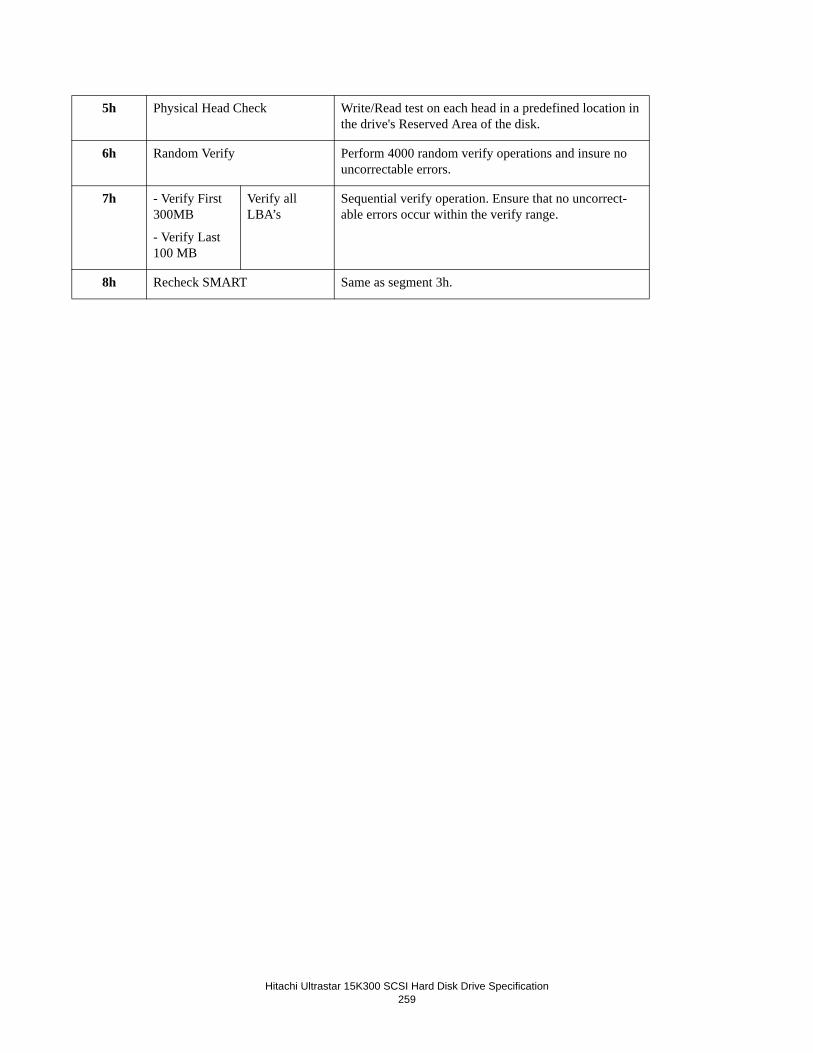
Hitachi Ultrastar 15K300 SCSI Hard Disk Drive Specification259
5h Physical Head Check Write/Read test on each head in a predefined location in the drive's Reserved Area of the disk.
6h Random Verify Perform 4000 random verify operations and insure no uncorrectable errors.
7h - Verify First 300MB
- Verify Last 100 MB
Verify all LBA’s
Sequential verify operation. Ensure that no uncorrect-able errors occur within the verify range.
8h Recheck SMART Same as segment 3h.
Hitachi Ultrastar 15K300 SCSI Hard Disk Drive Specification
260
20.18 Idle Time FunctionThe drive periodically saves data in logs and PFA counters in the reserved area of the disks. The information is used by the drive to support various SCSI commands and for the purpose of failure analysis.
20.19 Command Time out Limits The 'Command Time-out Limits' are defined as the time period from the SCSI Arbitration phase through the SCSI Task com-plete message, associated with a particular command.
The following times are for environments where Automatic Reallocation is disabled and there are no queued commands.
20.19.1 Reassignment TimeThe drive should be allowed a minimum of 5 seconds to complete a “Reassign Blocks” command.
20.19.2 Format TimeApproximately 90/45/25 minutes should be allowed for 300/147/73 GB capacity drives to complete a "Format Unit" command when certification is disabled. Allow 180/90/50 minutes when certification is enabled. If "Fast Format" is enabled via the FFMT bit in mode page 00h, allow 30 seconds for completion..
20.19.3 Start/Stop Unit TimeThe drive should be allowed a minimum of 30 seconds to complete a “Start Stop Unit” command (with Immed bit = 0). Initia-tors should also use this time to allow startup sequences initiated by auto start ups and “Start Stop Unit” commands (with Immed bit = 1) to complete and place the drive in a “ready for use” state.
Note: A time-out of one minute or more is recommended but NOT required. The larger system time-out limit allows the system to take advantage of the extensive ERP/DRP that the drive may attempt in order to successfully complete the startup sequence.

Hitachi Ultrastar 15K300 SCSI Hard Disk Drive Specification261
20.19.4 Medium Access Command TimeThe time-out limit for medium access commands that transfer user data or non-user data or both should be a minimum of 30 seconds. These commands are
Pre-Fetch
Read
Read Defect Data
Seek
Send Diagnostic (Function Code = 0)
Read Long
Reassign Blocks
Write
Write and Verify
Write Buffer
Write Same
Verify
Note: The 30-second limit assumes the absence of bus contention and data transfers of 64 blocks or less. This time should be adjusted for anticipated bus contention and if longer user data transfers are requested.
20.19.5 Time-out Limits for Other CommandsThe drive should be allowed a minimum of 5 seconds to complete these commands:
Inquiry
Log Select
Log Sense
Mode Select
Mode Sense
Persistent Reserve In/Out
Read Buffer
Read Capacity
Read Long
Release
Request Sense
Reserve
Set/Report Device Identifier
Start/Stop Unit (with Immed bit = 1)
Synchronize Cache
Test Unit Ready
Writer Long
The command time-out for a command that is not located at the head of the command queue should be increased by the sum of command time-outs for all of the commands that are performed before it is.

Hitachi Ultrastar 15K300 SCSI Hard Disk Drive Specification
262
20.20 Recommended Initiator ERPThe Drive's design points for error reporting to the system assumes certain system action for the error return codes. These assumptions are:
1. SCSI protocol will be the first priority in reporting errors.2. The system will maintain a log of all reported errors.3. System architecture should include all error handling recommendations made in this section. Deviations should have
mutual agreement between Drive development and system integration.
This section is directed toward documenting the assumptions made by the Drive that the system is expected to implement. The two error classes that the system should be concerned with are DATA and NON-DATA errors.
Data errors are those errors that deal with the handling of data to and from the MEDIA and are identified by the Additional Sense Code contained in the sense data. The Additional Sense Codes for data errors are as follows:
• OC - Write error
• 11 - Unrecovered read error
• 14 - No record found
• 16 - Data Synchronization mark error
• 17 - Recovered read error without ECC correction
• 18 - Recovered read error with ECC correction
Typically, data errors do not include positioning of the heads or the data path though the electronics.
Nondata errors are those errors that do not have a direct relationship with transferring data to and from the media. Nondata errors can include data handling if the media is not associated with the error (that is, interface error).
The system action assumed for each class of error is outlined here.
20.20.1 Drive Service StrategyThe Drive service strategy is defined so the customer will be able to use the system as soon after a failure is detected as possi-ble. The first priority is to replace the entire drive to make the system operational with minimal service time. The service rep-resentative should:
1. Back up all the customer data on this drive if possible2. Replace the complete drive3. Restore the customer data4. Return the drive to customer service

Hitachi Ultrastar 15K300 SCSI Hard Disk Drive Specification263
20.20.2 Recommendations for System Error LogThe system error log should contain information about the Drive error that will allow recovery actions. The system error logs should contain all the error information returned in the sense data. At a minimum, the following information about each error occurrence should be logged.
• Valid bit and error code (Sense byte 0)
• Sense Key (Sense byte 2)
• Information bytes (Sense bytes 3 through 6)
• Command specific information (Sense bytes 8 through 11)
• Additional Sense Code (Sense byte 12)
• Additional Sense Code Qualifier (Sense byte 13)
• Field Replaceable Unit (Sense byte 14)
• Sense Key Specific (Sense bytes 15, 16, and 17)
• Vender Unique error information (Sense bytes 20 through 23)
20.20.3 Data Recovery ProcedureStatistically, most data error activity is noise related and has nothing to do with defects in the media. It is wrong for the system to assume that every data error reported occurred because of a defect in the media. It is also wrong for the system to assume that every data error that occurred because of a media defect rendered the Drive unusable.
Recurring data error activity at the same physical location is an indication of a problem. The problem can be due to a media defect or magnetic damage. A media defect is physical damage to the recording capability of the media while magnetic dam-age is a defect in the bit pattern written to the media.
In both cases, the error can be corrected without replacing the unit. The physical sector may require relocation. The Drive determines the need to reassign a sector. The Mode Select Page 1 option bit ARRE (See Section 17.10.3, “Mode Page 01 (Read/Write Error Recovery Parameters)” on page 110) set active allows the Drive to relocate recovered read data errors. Non recovered data errors or the ARRE bit being inactive will have additional sense codes returned to recommend reassignment of sectors.
The need to reassign a sector should be infrequent. Sites not meeting error rate criteria are removed from use during SAT (Sur-face Analysis Test) in Drive manufacturing. With the exception of some early life SAT escapes (sites that were marginally missed during SAT), reassigning defective sectors should be rare. Frequent sector reassignment may be an (early) indication of another type of failure. Sector reassignments are monitored as part of the predictive failure analysis. When a threshold is exceeded, the Drive will notify the initiator that a scheduled service action is required.
Drive soft error rates are based on extraneous random faults that are not predictable. Media defects discovered after the Drive completes manufacturing final test need to be relocated so that soft error rates are not influenced by predictable known error sites. Failure of the system to properly relocate defective media sites can have a direct influence on system throughput and drive error rates.

Hitachi Ultrastar 15K300 SCSI Hard Disk Drive Specification
264
20.20.3.1 Reassign a Physical SectorThe Drive determines the need to reassign physical sectors based on error activity. Once a physical sector requires reassign-ment, the Drive will either reassign the physical sector, or recommend to the initiator that the LBA associated with the physical sector be reassigned.
When the following Sense Key, Additional Sense Code, and Additional Sense Code Qualifier combinations are returned, the initiator should reassign the LBA reported at the next opportunity.
Note: In Table 196, the Key, Code, and Qualifier fields are all hex values (i.e., Sense Key 1 is 1h, Sense Code 17 is 17h, etc.).
Table 196: Recommend Reassign Errors
To reassign an LBA that has sense data recommending a reassignment, the initiator should:
1. Attempt to recover the data from the sector being reassigned with a Read (08) or Read (28) command.2. Reassign the LBA using the Reassign Blocks (07) command.
- If the reassignment completes successfully (Good Status), log the error in the system error log.
- If the reassignment completes unsuccessfully (Check Condition Status), follow the procedure in Section 20.20.3.3, “Reassign Blocks Recovery” on page 265.
3. Write the LBA that was reassigned.
20.20.3.2 Data Error LoggingThe Drive will report data errors to the initiator that do not require immediate action (successful auto reallocation, successful auto rewrite, or no action needed on this occurrence). The initiator should log these errors in the system error log. No other action is required.
Table 197: Log Only Errors
Key Code Qual Description
1 17 07 Recovered Data without ECC - Recommend Reassignment
1 18 05 Recovered Data with ECC - Recommend Reassignment
Key Code Qual Description
1 16 00 Data Synchronization Mark Error
1 17 01 Recovered Data with Retries
1 17 06 Recovered Data without ECC - Auto Reallocated
1 17 09 Recovered Data without ECC - Data Rewritten
1 18 00 Recovered Data with ECC
1 18 02 Recovered Data with ECC - Auto Reallocated
1 18 07 Recovered Data with ECC - Data Rewritten

Hitachi Ultrastar 15K300 SCSI Hard Disk Drive Specification265
20.20.3.3 Reassign Blocks RecoveryThe Drive provides the capability to remove media defects without reducing capacity. If the mode parameter bit ARRE is active, the Drive will automatically reallocate LBA's determined to be defective. For those LBA's where the error is unrecov-erable or the initiator elects to not have the Drive automatically reallocate LBA's, the Drive will recommend reassignment of the LBA.
Recovery from a failed reassignment consists of the following actions:
• Updating the defect descriptor to remove the LBA's that have been successfully reassigned and then retry the Reas-sign Blocks command. The LBA contained in the Command Specific Information field of the Sense Data is the LBA in the first defect descriptor that was not reassigned because of the failure. If the command failed because of an unre-coverable read error other than those specified in the defect descriptor, add this LBA to the defect descriptor and retry the command. Refer to Section 17.25, “REASSIGN BLOCKS (07)” on page 167, for additional information.
• If the retried Reassign Blocks (07) command completes successfully, returning to normal processing.
• If the retried Reassign Blocks (07) command fails, servicing the drive using the service guidelines recommended in Section 20.20.1, “Drive Service Strategy” on page 262.
20.20.4 Nondata Error Recovery ProcedureThe Drive will follow a logical recovery procedure for nondata errors. The initiator options for non-data errors are limited to logging the error, retrying the failing command, or replacing the drive.
These recovery procedures assume the initiator practices data back-up and logs errors at the system level for interrogation by service personnel.
20.20.4.1 Drive BusyThe Drive is busy performing an operation. This is not an error condition. The initiator can test for completion of the opera-tion by issuing Test Unit Ready (00) (or media access) commands.
• If the Test Unit Ready (00) (or media access) command completes with Check Condition Status then issue a Request Sense (03)
- If the specified recovery procedure for the sense data is for a condition other than drive busy, follow the recovery procedure for the condition reported.
- If the specified recovery procedure for the sense data is for a drive busy condition, then continue re-issuing the Test Unit Ready (00) and Request Sense commands for the duration of a media access time-out or until the drive returns Good Status.
- If the drive has been busy for longer than the limit specified in Section 20.19, “Command Time out Limits” on page 260, then service the drive using the service guidelines recommended in Section 20.20.1, “Drive Service Strategy” on page 262. Otherwise return to normal processing.
• If the Test Unit Ready (00) (or media access) command completes with Good Status, then return to normal process-ing.
20.20.4.2 Unrecovered Drive ErrorThe initiator should retry the failing command.
1. If the retry of the failing command completes with Good Status or recovered Sense Key, follow the recovery procedure in Section 20.20.4.3, “Recovered Drive Error” on page 266.
2. If the retry of the failing command completes with hardware error sense, verify there is no outside cause (e.g., power supply) for the failure, then retry the failing command. a. If the retry of the failing command completes with Good Status, follow the recovery procedure in next Section
20.20.4.3, “Recovered Drive Error” on page 266.b. If the retry of the failing command completes with Recovered sense or Hardware error sense, then service the drive
using the service guideline recommended in Section 20.20.1, “Drive Service Strategy” on page 262.

Hitachi Ultrastar 15K300 SCSI Hard Disk Drive Specification
266
20.20.4.3 Recovered Drive ErrorThe Initiator should log the error as soft with the recovery level.
20.20.4.4 Drive Not ReadyThe initiator should do the following:
1. Issue a Start Stop Unit (1B) command.2. Verify that the drive comes ready within the time specified in Section 4.5.2, “Drive ready time” on page 12.3. If the drive fails to come ready within the specified time, service the drive using the service guidelines specified in Sec-tion 20.20.1, “Drive Service Strategy” on page 262.
4. Retry the failing command. a. If the failing command completes with Good Status, log the error as recovered.b. If the failing command completes with Not Ready sense, verify there is no outside cause (for example, the power
supply). Then service the drive using the service guidelines specified in Section 20.20.1, “Drive Service Strategy” on page 262.
20.20.4.5 No Defect SpareThree conditions can cause this error:
1. When the Reassign Blocks (07) command is issued and there are no spares available for the Drive to use for the reloca-tion requested.
2. When the Glist is full and the sector to be reassigned cannot be added.3. During a format operation, there was not enough space available to fulfill the spare requirement (Dlist is too large).
Service the Drive following Section 20.20.1, “Drive Service Strategy” on page 262.
20.20.4.6 Degraded ModeRefer to Section 20.1.9, “Degraded Mode” on page 242, for the definition of this state. There are three causes for entering degraded mode. In all cases the Sense Key is Not Ready. The causes are the following:
1. Sense Code/Qualifier of Logical Unit Not Ready, initializing command required. The spindle motor not spinning or not at the proper speed. This may not be an error condition. The initiator should issue a Unit start (1B) command to start the spindle motor. If the Drive fails to come ready in the time specified in Section 20.19, “Command Time out Limits” on page 260, service the drive using the service guideline recommended in Section 20.20.1, “Drive Service Strategy” on page 262.
2. Sense Code/Qualifier of Diagnostic Failure. Failure of a Send Diagnostic self test, a start up sequence, or other internal target failures.
- Failure of a send diagnostic self test or a start up sequence.
This failure is the result of the diagnostics that are executed during power on or when the Send Diagnostic (1D) com-mand is executed detecting a failure. As with the RAM code not loaded and the configuration data not loaded, the recovery is either a power cycle or issuing the Send Diagnostic (1D) command with the self test bit set active.Recovery for a failed Send Diagnostic (1D) is achieved in one of the following ways:
Executing the Send Diagnostic (1D) command
Power cycling the drive
If the failure repeats, service the drive using the service guideline recommended in Section 20.20.1, “Drive Service Strategy” on page 262.
Recovery for a failed power up sequence is achieved in one of the following ways:
Issuing a Unit start (1B) command
Power cycling the drive.
If the failure repeats, service the drive using the service guideline recommended in Section 20.20.1, “Drive Service Strategy” on page 262.
Hitachi Ultrastar 15K300 SCSI Hard Disk Drive Specification267
- Internal target failures
The drive periodically adjusts the track following for each head to compensate for expansion and contraction of the disks due to temperature changes. If one of these adjustments fails, the drive will enter a degraded mode to prevent writing data off track.
Recovery of this condition is either a power cycle or successful completion of the Send Diagnostic (1D). Service the drive using the recommended service guidelines specified in Section 20.20.1, “Drive Service Strategy” on page 262, if the power cycle or the Send Diagnostic (1D) command fail to complete successfully.
3. Sense Code/Qualifier of Format Command Failed Format Unit (04), Sense Code/Qualifier of Medium Format Cor-rupted Reassign Failed Reassign Blocks (07) command, or an automatic reallocation failed or was abnormally termi-nated.
Recovery from a failed Format Unit (04) is achieved by retrying the command. If the command fails a second time, ser-vice the drive following the procedure defined in Section 20.20.1, “Drive Service Strategy” on page 262.
If the above defined recovery procedures fail to clear the degraded mode condition, the Drive should be replaced. Follow the procedure in Section 20.20.1, “Drive Service Strategy” on page 262, when replacing the drive.
20.20.4.7 Reserved Area Hard ErrorSectors found defective in the reserved area of the disk cannot be reassigned after the Drive leaves the factory. The data in the reserved area is not directly accessible by the initiator. For this reason, the reserved area has duplicate copies of all data. A data error must occur in both copies of the data record before the Drive considers a reserved area read error. When this happens, the integrity of the drive is questionable.
Service the Drive using Section 20.20.1, “Drive Service Strategy” on page 262.
20.20.4.8 Interface ProtocolFor all interface protocol errors, the initiator should complete the following steps:
1. Correct the parameter that caused the Illegal Request2. Retry the failing command3. If the first retry of the failing command completes with
- Good Status, log the error as recovered
- Check Condition Status with sense data for an Illegal Request, verify there is no outside cause (for example, the power supply) for the failure
- Other, follow the recommendations for the error condition reported. Retry the failing command. If this retry of the failing command completes with
• Good Status, log the error as recovered
• Check Condition Status with sense data for an Illegal Request, service the drive using the service guideline rec-ommended in Section 20.20.1, “Drive Service Strategy” on page 262.
• Other, follow the recommendations for the error condition reported.
20.20.4.9 Aborted CommandThe initiator should determine the cause from the Additional Sense Code (byte 12):
• Sense Key = B (Aborted Command) with Additional Sense Codes of 1B, 25, 43, 49, and 4E are initiator caused abort conditions. The initiator should correct the condition that caused the abort and retry the failing command.
• Sense Key = B (Aborted Command) with Additional Sense Code of 44 or 48 are drive caused abort conditions. The initiator should:1. Retry the failing command.2. If the retry of the failing command completes with

Hitachi Ultrastar 15K300 SCSI Hard Disk Drive Specification
268
- Good Status, log the error as recovered.
- Abort Command Sense, verify there is no outside cause (e.g. power supply) for the failure.3. Retry the failing command.4. If the retry of the failing command completes with
- Good Status, log the error as recovered.
- Abort command sense, then service the drive using the service guideline recommended in Section 20.20.1, “Drive Service Strategy” on page 262.
• Sense Key = B (Aborted Command) and an Additional Sense Code of 47 can be an initiator or Drive caused abort condition. The initiator should follow the above procedure for initiator caused abort conditions if the Drive detected the SCSI bus parity error. The initiator should follow the above procedure for Drive caused abort conditions if the ini-tiator detected the SCSI bus parity error.
20.20.4.10 Unit Attention ConditionUnit Attention Conditions are not errors. They alert the initiator that the drive had an action that may have changed an initiator controlled state in the drive. These conditions are the following:
Not Ready to Ready Transition
Not ready to ready transition, unit formatted. This Unit Attention Condition will not be reported to the initiator that issued the Format Unit (04).
Reset
Reset - This means the drive was reset by either a power-on reset, Bus reset, a Target Reset message, Transceiver Mode Changed reset, or an internal reset.
Mode Parameters Changed
A Mode Select (15) command successfully completed. This means that the mode parameters that are the current value may have changed. The parameters may or may not have changed but the command to change the parameters successfully com-pleted. The Drive does not actually compare the old current and the new current parameters to determine if the parameters changed. This Unit Attention Condition will not be reported to the initiator that issued the Mode Select (15).
Microcode Has Changed
Write Buffer (3B) to download microcode has successfully completed. This means that the microcode that controls the Drive has been changed. The code may or may not be the same as the code currently being executed. The Drive does not compare old level code with new code.
Commands Cleared by Another Initiator
Tagged commands cleared by a clear queue message. This means that the command queue has been cleared. The Unit Atten-tion Condition is not reported to the initiator that issued the clear queue message. Unit Attention Condition is reported to all initiators that had commands active or queued.
Reissue any outstanding command.
Log Select Parameters Changed
A Log Select (4C) command successfully completed. This means that the Log Select command cleared statistical information successfully (See Section 17.6, “LOG SELECT (4C)” on page 72). Unit Attention Condition is reported to all initiators excluding the initiator that issued the Log Select command.
Device Identifier Changed
A Set Device Identifier (A4) command successfully completed. This means that the Set Device Identifier information field has been updated. (See 17.40, “SET DEVICE IDENTIFIER (A4/06)” on page 191) A Unit Attention Condition is reported to all initiators excluding the initiator that issued the Set Device Identifier command.

Hitachi Ultrastar 15K300 SCSI Hard Disk Drive Specification269
20.20.4.11 Components MismatchThe compatibility test is performed at a power cycle. The compatibility test verifies the microcode version of the electronics. When the Drive detects the microcode version mismatch, the most likely cause is the result of incorrect parts used during a ser-vice action.
If the error reported is Key/code/qualifier 4/40/80, Diagnostic failure, bring-up fail, the initiator should do the following:
1. Retry Power cycle
2. Check the send diagnostic end status. If the status is
- GOOD, Return to normal processing
- Check Condition Status, issue a Request Sense (03) and follow the recommendations for the sense data returned unless the sense data is for a component mismatch. If the sense data is for component mismatch, service the drive using the service guideline recommended in Section 20.20.1, “Drive Service Strategy” on page 262.
20.20.4.12 Self Initiated ResetThe Drive will initiate a self reset when the condition of the Drive cannot be determined. The internal reset will terminate any outstanding commands, release any reserved initiators, and stop the spindle motor. The initiator can recover by
1. Logging the error
2. Retrying the failing command. If the failing command completes with:
- Good Status, return to normal processing
- Self initiated reset sense, service the drive according the guidelines recommended in Section 20.20.1, “Drive Ser-vice Strategy” on page 262.
- Other, follow the recommendations for the error reported.
20.20.4.13 Defect List RecoveryThis is not an error condition.
The initiator either requested a defect list in a format (block or vendor specific) that the Drive does not support or the requested defect list(s) exceed the maximum list length that can be returned. If the Sense Key/Code/Qualifier are:
1/1F/00, the requested list(s) exceed the maximum length that can be supported. The initiator should request one list at a time. If a single list exceeds the maximum returnable length, this may be an indication of a marginally operational drive. Service the drive following the service guidelines in Section 20.20.1, “Drive Service Strategy” on page 262.
1/1C/01 or 1/1C/02, the requested defect list is not in the format that the Drive supports. The requested defect list is returned in the physical (cylinder, sector, head) format. This is the default format. There is no initiator action required for this condition.

Hitachi Ultrastar 15K300 SCSI Hard Disk Drive Specification
270
20.20.4.14 Miscompare RecoveryA miscompare can occur on a Verify (2F) command or a Write and Verify (2E) with the byte check (BytChk) bit active. Recovery for a mis-compare error is different for the two commands.
Verify Command
The initiator should do the following:
1. Verify that the data sent to the drive is the correct data for the byte-by-byte compare.
2. Read the data from the media with a Read (08) or Read (28) command and verify that the data from the media is the expected data for the byte-by-byte compare.
- If all data are correct, this is an indication that the data may have been read from the media incorrectly without an error detected. Service the drive using the procedure specified in Section 20.20.1, “Drive Service Strategy” on page 262.
- If all data are not correct, this is an indication that the data on the media is not the data the initiator expected. Rewrite the correct data to the media.
Write and Verify Command
The drive uses the same data in the data buffer to write then read and compare. A miscompare error on the Write and Verify (2E) command is an indication that the drive cannot reliably write or read the media. Service the drive using the procedures specified in Section 20.20.1, “Drive Service Strategy” on page 262.
20.20.4.15 Microcode Error
The microcode from the interface is validated before the device operates using that microcode. When the validation detects incorrect or incomplete data, the Drive enters degraded mode.
If the initiator attempted to load microcode using the Write Buffer (3B) retry the Write Buffer (3B). If the command completes with
• Good Status - return to normal processing
• Check Condition Status - service the drive using the service guidelines recommended in Section 20.20.1, “Drive Service Strategy” on page 262.
If the check sum error occurred during normal processing, the initiator may attempt to load microcode before deciding to service the drive using the service guidelines recommended in Section 20.20.1, “Drive Service Strategy” on page 262.
To load new microcode, the initiator should issue a Write Buffer (3B) command with the download and save option. If the Write Buffer (3B) command completes with
• Good Status, return to normal processing. Retry the failing command. If the task complete with
- Good Status - Continue normal processing.
- Check Condition Status for check sum error - Service the drive using the service guidelines recommended in Section 20.20.1, “Drive Service Strategy” on page 262.
- Check Condition Status for any other error - follow the recommended recovery procedure for the error reported.
• Check Condition Status for Check sum error, service the drive using the service guidelines recommended in Section 20.20.1, “Drive Service Strategy” on page 262.
• Check Condition Status for any other error, follow the recommendations for the returned sense data.
20.20.4.16 Predictive Failure AnalysisThe Drive performs error log analysis and will alert the initiator of a potential failure. The initiator should determine if this device is the only device with error activity.
If this drive is the only drive attached to the initiator with error activity, service the drive using the procedures specified in Sec-tion 20.20.1, “Drive Service Strategy” on page 262.
Note: Service for this drive can be deferred. The longer service is deferred, the more probable a failure can occur that will require immediate service.
If more than this drive is experiencing error activity, the drive is probably not at fault. Locate and service the outside source causing error activity on this drive.
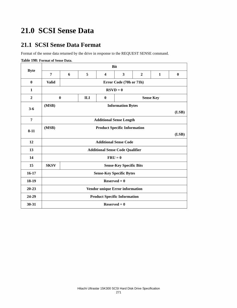
Hitachi Ultrastar 15K300 SCSI Hard Disk Drive Specification
271
21.0 SCSI Sense Data
21.1 SCSI Sense Data FormatFormat of the sense data returned by the drive in response to the REQUEST SENSE command.
Table 198: Format of Sense Data.
ByteBit
7 6 5 4 3 2 1 0
0 Valid Error Code (70h or 71h)
1 RSVD = 0
2 0 ILI 0 Sense Key
3-6(MSB) Information Bytes
(LSB)
7 Additional Sense Length
8-11(MSB) Product Specific Information
(LSB)
12 Additional Sense Code
13 Additional Sense Code Qualifier
14 FRU = 0
15 SKSV Sense-Key Specific Bits
16-17 Sense-Key Specific Bytes
18-19 Reserved = 0
20-23 Vendor unique Error information
24-29 Product Specific Information
30-31 Reserved = 0

Hitachi Ultrastar 15K300 SCSI Hard Disk Drive Specification
272
21.2 Sense Data Description
21.2.1 Valid (Bit 7 of byte 0)0 The Information Bytes (byte 3 through 6) are not defined.
1 The Information Bytes (byte 3 through 6) contain a valid logical block address.
21.2.2 Error Code (Bit 6 - 0 of byte 0)70h Current Error. This indicates an error for the current command.
71h Deferred Error. This indicates that the error is for a previous command that has already returned a good sta-tus. Such commands are associated with the immediate bit or write caching. Format unit (04h) command is an example of a command that may return a deferred error.
21.2.3 ILI: Incorrect Length Indicator (Bit 5 of byte 2)The ILI bit is valid for the Read Long (3Eh) command and Write Long (3Fh) command only. ILI set to one and Valid Bit set to one indicates that the requested logical block length does not match the logical block length of the data on the medium for a Read Long or Write Long command. The Information field contains residue information about the error. ILI set to zero indi-cates there is no incorrect length condition.
0 No Incorrect Length condition.
1 Incorrect Length Indicated.
Valid ILI Command = Read Long or Write Long? Description
x 0 x No incorrect length condition
1 1 yes Requested Logical block Length does not match the logical block length of the data on the disk
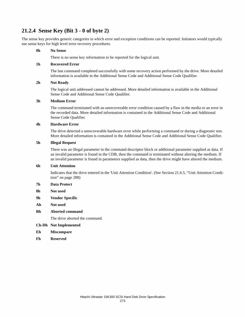
Hitachi Ultrastar 15K300 SCSI Hard Disk Drive Specification
273
21.2.4 Sense Key (Bit 3 - 0 of byte 2)The sense key provides generic categories in which error and exception conditions can be reported. Initiators would typically use sense keys for high level error recovery procedures.
0h No Sense
There is no sense key information to be reported for the logical unit.
1h Recovered Error
The last command completed successfully with some recovery action performed by the drive. More detailed information is available in the Additional Sense Code and Additional Sense Code Qualifier.
2h Not Ready
The logical unit addressed cannot be addressed. More detailed information is available in the Additional Sense Code and Additional Sense Code Qualifier.
3h Medium Error
The command terminated with an unrecoverable error condition caused by a flaw in the media or an error in the recorded data. More detailed information is contained in the Additional Sense Code and Additional Sense Code Qualifier.
4h Hardware Error
The drive detected a unrecoverable hardware error while performing a command or during a diagnostic test. More detailed information is contained in the Additional Sense Code and Additional Sense Code Qualifier.
5h Illegal Request
There was an illegal parameter in the command descriptor block or additional parameter supplied as data. If an invalid parameter is found in the CDB, then the command is terminated without altering the medium. If an invalid parameter is found in parameters supplied as data, then the drive might have altered the medium.
6h Unit Attention
Indicates that the drive entered in the 'Unit Attention Condition'. (See Section 21.6.5, “Unit Attention Condi-tion” on page 288)
7h Data Protect
8h Not used
9h Vendor Specific
Ah Not used
Bh Aborted command
The drive aborted the command.
Ch-Dh Not Implemented
Eh Miscompare
Fh Reserved

Hitachi Ultrastar 15K300 SCSI Hard Disk Drive Specification
274
21.2.5 Information Bytes (Byte 3 through 6)This field is only valid when Valid Bit is one.
• ILI = 0: This field contains the unsigned LBA associated with the sense key. The LBA reported will be within the LBA range of the command as defined in the CDB.
Note: An LBA other than the command LBA may be reported on the Reassign Block (07h) command.
• ILI = 1: This field contains the difference (residue) of the requested length in bytes. Negative values are indicated by two's complement notation.
21.2.6 Additional Sense Length (Byte 7)Indicates the remaining number of bytes in the sense data. (It is always set to 18h.)
21.2.7 Command Specific Information (Byte 8 through 11)The values in this field vary with products. Please see the individual product specification for more details.
Valid ILI Description
0 x 0x00000000 - (not used/invalid)
1 0 LBA
1 1 Residue of the requested length in bytes
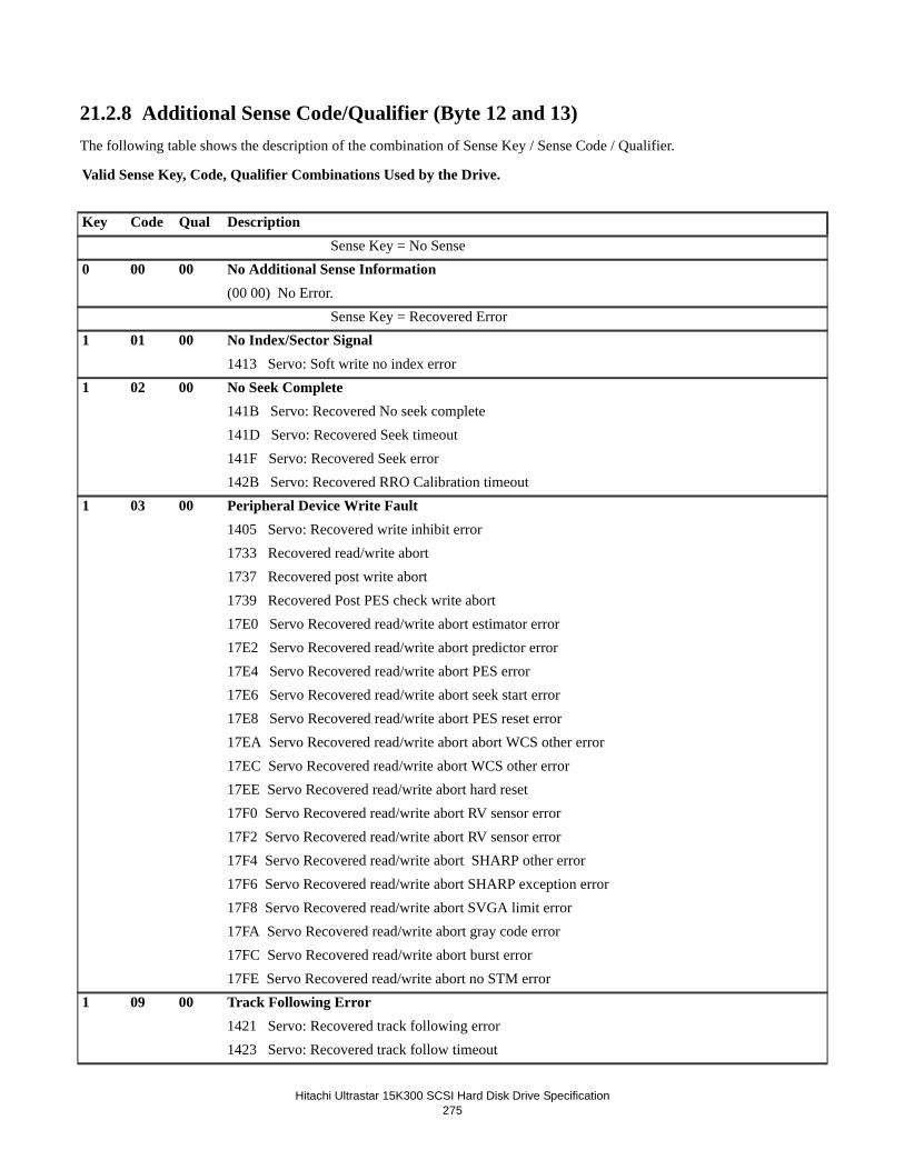
Hitachi Ultrastar 15K300 SCSI Hard Disk Drive Specification
275
21.2.8 Additional Sense Code/Qualifier (Byte 12 and 13)The following table shows the description of the combination of Sense Key / Sense Code / Qualifier.
Valid Sense Key, Code, Qualifier Combinations Used by the Drive.
Key Code Qual Description Sense Key = No Sense
0 00 00 No Additional Sense Information(00 00) No Error. Sense Key = Recovered Error
1 01 00 No Index/Sector Signal1413 Servo: Soft write no index error
1 02 00 No Seek Complete141B Servo: Recovered No seek complete141D Servo: Recovered Seek timeout141F Servo: Recovered Seek error142B Servo: Recovered RRO Calibration timeout
1 03 00 Peripheral Device Write Fault1405 Servo: Recovered write inhibit error1733 Recovered read/write abort1737 Recovered post write abort1739 Recovered Post PES check write abort17E0 Servo Recovered read/write abort estimator error17E2 Servo Recovered read/write abort predictor error17E4 Servo Recovered read/write abort PES error17E6 Servo Recovered read/write abort seek start error17E8 Servo Recovered read/write abort PES reset error17EA Servo Recovered read/write abort abort WCS other error17EC Servo Recovered read/write abort WCS other error17EE Servo Recovered read/write abort hard reset17F0 Servo Recovered read/write abort RV sensor error17F2 Servo Recovered read/write abort RV sensor error17F4 Servo Recovered read/write abort SHARP other error17F6 Servo Recovered read/write abort SHARP exception error17F8 Servo Recovered read/write abort SVGA limit error17FA Servo Recovered read/write abort gray code error17FC Servo Recovered read/write abort burst error17FE Servo Recovered read/write abort no STM error
1 09 00 Track Following Error1421 Servo: Recovered track following error1423 Servo: Recovered track follow timeout

Hitachi Ultrastar 15K300 SCSI Hard Disk Drive Specification
276
1 0B 01 Temperature Warning ErrorxA02 Temperature Warning
1 0B 03 Background Selftest Failure WarningxA03 Background selftest failure warning
1 0B 04 Background Pre-Scan Failure WarningxA04 Background pre-scan failure warning
0 0B 05 Background Media Scan Failure WarningxA05 Background media scan failure warning
1 0C 01 Recovered Write Error with Auto Reallocation - Auto ReallocatedD703 Auto-reallocated due to write error
1 0C 03 Recovered Write Error - Recommend Reassignment1704 Recommend reassign due to write error
1 15 00 Random Positioning Error1714 Recovered sector overflow173D Recovered sector miss1770 Recovered SID timeout17B2 Recovered abort window error
1 16 00 Data Synchronization Mark Error173B Recovered data address mark error
1 16 01 Data Sync Error - Data RewrittenE70E Recovered Data Address Mark error - rewritten
1 16 02 Data Sync Error - Recommend RewriteE70F Recovered Data Address Mark error - recommend rewrite
1 16 03 Data Sync Error - Auto ReallocatedD710 Recovered Data Address Mark error - reassigned
1 16 04 Data Sync Error - Recommend ReassignmentE711 Recovered Data Address Mark error - recommend reassign
1 17 01 Recovered Data with Retries1722 Recovered small thermal asperity172C Recovered media error172E Recovered media error (off-line correction discarded)
1 17 06 Recovered Data Without ECC - Data Auto-ReallocatedE705 Media error with OTF correction - reassignedD72B Recovered thermal asperity - reassigned
1 17 07 Recovered Data Without ECC - Recommend ReassignmentE706 Media error with OTF correction - recommend reassignE72A Recovered thermal asperity - recommend reassign
1 17 08 Recovered Data Without ECC - Recommend RewriteE707 Media error with OTF correction - recommend rewriteE729 Recovered thermal asperity - recommend rewrite

Hitachi Ultrastar 15K300 SCSI Hard Disk Drive Specification
277
1 17 09 Recovered Data Without ECC - Data RewrittenD708 Media error with OTF correction - rewrittenE728 Recovered thermal asperity - rewritten
1 18 00 Recovered Data With ECC1709 Media error with offline correction
1 18 02 Recovered Data - Data Auto-ReallocatedD70A Media error with offline correction and reassignD724 Recovered thermal asperity with offline correction - reassigned
1 18 05 Recovered Data - Recommend ReassignmentE70B Media error with offline correction and recommend reassignE725 Recovered thermal asperity with offline correction - recommend reassign
1 18 06 Recovered Data With ECC - Recommend RewriteE70C Media error with offline correction - recommend rewriteE726 Recovered thermal asperity with offline correction - recommend rewrite
1 18 07 Recovered Data With ECC - Data RewrittenE70D Media error with offline correction - rewrittenE727 Recovered thermal asperity with offline correction - rewritten
1 1C 00 Defect List Format Not Supported1746 Defect list format not supported
1 1C 01 Primary Defect List Not Found. Requested Format Not Supported1747 Primary defect list not found (Read Defect Data only)
1 1C 02 Grown Defect List Not Found. Requested Format Not Supported1748 Grown defect list not found (Read Defect Data only)
1 1F 00 Partial Defect List Transfer1749 Partial defect list transferred (Defect list longer than 64KB, 64 KB of data returned - Read Defect Data only)
1 44 00 Internal Target FailureF123 Invalid request to enter sleep modeF128 DRAM test in progressF129 DRAM test completeF12A DRAM test errorF132 GEM FH track read error1201 Error in UEC class1202 Error in UEC cause1301 Motor: Recovered internal error1303 Motor: Recovered Open Loop Commutation failure1305 Motor: Recovered No feedback detected1307 Motor: Recovered Settle timeout1309 Motor: Recovered Gross speed error130B Motor: Recovered 12V OK error

Hitachi Ultrastar 15K300 SCSI Hard Disk Drive Specification
278
130D Motor: Recovered Speed error1311 Motor: Recovered Internal 12V not OK timeout1313 Motor: Recovered Iductive Sense measurement timeout1315 Motor: Recovered Spin Sense speed error1319 Motor: Recovered Target speed error131B Motor: Recovered Power driver version error131D Motor: Recovered Over current error1321 Motor: Recovered Negative regulator fault1323 Motor: Recovered Module overtemp error1325 Motor: Recovered 12V or 5V OK error1327 Motor: Recovered unknown error1401 Servo: Recovered Requested rezero head does not exist1403 Servo: Recovered Back EMF movement in progress1405 Servo: Recovered Back EMF timeout error1407 Servo: Recovered ADC conversion timeout1409 Servo: Recovered Load/unload calibration error140B Servo: Recovered Invalid 5 volts140D Servo: Recovered Invalid 12 volts140F Servo: Recovered Invalid harmonic requested1411 Servo: Recovered Gain BEMF Calibration error1413 Servo: Recovered VOFF BEMF calibration error1415 Servo: Recovered Invalid temperature1417 Servo: Recovered Truncated rezero1419 Servo: Recovered Heads not loaded1425 Servo: Recovered KT Seek out of range1427 Servo: Recovered DAC Offset calibration error1429 Servo: Recovered Load speed error142D Servo: Recovered ADC Calibration error142F Servo: Recovered ADC Offset error1431 Servo: Recovered ADC Limit error1433 Servo: Recovered Balancer Resistance error1435 Servo: Recovered Balancer Resistance Limit error1437 Servo: Recovered First Cylinder error1439 Servo: Recovered Valid Cylinder error143B Servo: Recovered ADC Saturation error143D Servo: Recovered Latch Break timeout143F Servo: Recovered MR Resistance out of range error1441 Servo: Recovered VCM Retract error1443 Servo: Recovered Load Retry error1445 Servo: Recovered DFT Sharp error

Hitachi Ultrastar 15K300 SCSI Hard Disk Drive Specification
279
1447 Servo: Recovered Load/Unload state error1606 Recovered data with PPM or precomp load1608 Recovered data with TA (Thermal Asperity) detection160A Recovered data with SMM or VM or DDF160C Recovered data with pre-PPM or FH (Fly Height) detection160E Recovered data with write or pre-TA detection1610 Recovered data with pre-SMM or VM or STM or DDF1612 Recovered data with NRZ parity error1614 Recovered parity PP correction or STW1616 Recovered channel error1618 Recovered AE thermal asperity161A Recovered AE open MR element error161C Recovered AE IC over temperature error161E Recovered AE IP clock count error1620 Recovered AE write data BLS error1624 Recovered AE invalid head address error1626 Recovered AE power supply error162A Recovered AE write transition error162C Recovered AE no write head current error162E Recovered Channel Pre-TA error1630 Recovered Channel write or NRZ parity error1632 Recovered Channel write synth unlock error1634 Recovered AE Short write read head error1636 Recovered AE Short write head error1638 Recovered AE Non-selected write head error163C Recovered AE IH open short error163E Recovered AE IH delay error1640 Recovered Channel coarse tune timeout error1642 Recovered AE Readback error1712 Recovered ECC error1716 Recovered overrun171A Recovered ECC overrun171C Recovered DRAM CRC error171E Recovered ID Parity error1731 Recovered write fault1759 Unknown recovered error1792 Recovered Current pointer error1798 Recovered ID not found error179C Recovered Channel write or NRZ parity error17B4 Recovered Shock sensor error

Hitachi Ultrastar 15K300 SCSI Hard Disk Drive Specification
280
17B8 Recovered Reference tag error17BA Recovered Application tag error17BC Recovered Guard check error17BE Recovered Channel write synthesis unlock error17C0 Recovered End sector check error17C2 Recovered Read CRC error17C4 Recovered DRAM ECC error17C6 Recovered DRAM ECC LBA error17C8 Recovered DRAM Write error
1 44 0B Vendor Unique - Internal Target Failure130F Motor: Recovered Spindle Current error1317 Motor: Recovered Spin Sense timeout131F Motor: Recovered System clock watchdog error1329 Motor: Recovered VCM DAC watchdog error
1 5D 10 Predictive Failure Analysis Threshold ReachedxAFE SMART: Extreme over-temperature warning
1 5D 50 Predictive Failure Analysis Threshold ReachedxA50 SMART: Load/unload cycle count warning
1 5D 5B Predictive Failure Analysis Threshold ReachedxA5B SMART: Spin-up retry count warning
1 5D 62 Predictive Failure Analysis Threshold ReachedxA32 SMART: Read error rate warningxA4A SMART: Write error rate warning
1 5D 63 Predictive Failure Analysis Threshold ReachedxA43 SMART: Seek error rate warning
1 5D 64 Predictive Failure Analysis Threshold ReachedxA14 SMART: Spare sector availability warning
1 5D 66 Predictive Failure Analysis Threshold ReachedxA56 SMART: Spin-up time warning
1 5D FF Predictive Failure Analysis Threshold ReachedxAFF SMART: Test warning
1 81 00 Vendor Unique - Internal Logic Error1601 Channel/AE internal logic error1718 Recovered Abort immediate error Sense Key = Not Ready
2 04 00 Logical Unit Not Ready - Start Spindle Motor Fail1501 Logical unit not ready
2 04 01 Logical Unit Is In The Process of Becoming Ready1502 Logical unit becoming ready
2 04 02 Logical Unit Not Ready, initializing command required

Hitachi Ultrastar 15K300 SCSI Hard Disk Drive Specification
281
F124 Bring-up error1503 Logical unit not ready - initializing command required
2 04 03 Logical Unit Not Ready, Manual Intervention Required1572 Not ready - manual intervention required1573 Commands cleared due to power failure event (SAS)
2 04 04 Logical Unit Not Ready, Format In Progress1504 Not ready - format in progress
2 04 09 Not Ready - Self-test In Progress1505 Not ready - self-test in progress
2 04 11 Not Ready - Notify (Enable Spin-up) Required1553 Not ready - Notify (Enable Spin-up) required (SAS only)
2 04 F0 Vendor Unique - Logical Unit Not ReadyF133 BATS error: Vendor ID mismatch
2 31 00 Medium Format Corrupted - Reassign Failed1506 Reassign failed
2 31 01 Format Command Failed1507 Format failed Sense Key = Medium Error
3 03 00 Medium Error - Write FaultF734 Unrecovered read/write abortF738 Unrecovered post write abortF73A Unrecovered Post PES check write abortF7E1 Servo Unrecovered read/write abort estimator errorF7E3 Servo Unrecovered read/write abort predictor errorF7E5 Servo Unrecovered read/write abort PES errorF7E7 Servo Unrecovered read/write abort seek start errorF7E9 Servo Unrecovered read/write abort PES reset errorF7EB Servo Unrecovered read/write abort SID unlock errorF7ED Servo Unrecovered read/write abort WCS other errorF7EF Servo Unrecovered read/write abort hard resetF7F1 Servo Unrecovered read/write abort RV sensor errorF7F3 Servo Unrecovered read/write abort RV sensor errorF7F5 Servo Unrecovered read/write abort SHARP other errorF7F7 Servo Unrecovered read/write abort SHARP exception errorF7F9 Servo Unrecovered read/write abort SVGA limit errorF7FB Servo Unrecovered read/write abort gray code errorF7FD Servo Unrecovered read/write abort burst errorF7FF Servo Unrecovered read/write abort no STM error
3 11 00 Unrecovered Read ErrorF702 Too many notches

Hitachi Ultrastar 15K300 SCSI Hard Disk Drive Specification
282
F723 Unrecovered small thermal asperityF702 Too many notchesF72D Unrecovered media errorF72F Unrecovered media error (off-line correction discarded)F753 G-list full (Format command)F754 G-list full (2) (Format command)F755 Pointer repeat size errorF756 DST slot size errorF757 P-list fullF758 Spare list full
3 15 00 Random Positioning ErrorF715 Unrecovered sector overflowF73E Unrecovered sector missF771 Unrecovered SID timeoutF7B3 Unrecovered abort window error
3 16 00 Data Synchronization Mark ErrorF73C Unrecovered data address mark error
3 19 02 Defect List Error in Primary ListF74B Primary defect list error
3 19 03 Defect List Error in Grown ListF74C Grown defect list error
3 31 00 Medium Format Corrupted Reassign FailedF701 Format corrupted
3 81 00 Vendor Unique - Internal Logic ErrorF719 Recovered Abort immediate errorF75B Too many sectors Sense Key = Hardware Error
4 02 00 No Seek CompleteF41C Servo: Unrecovered No seek completeF41E Servo: Unrecovered Seek timeoutF420 Servo: Unrecovered Seek errorF42C Servo: Unrecovered RRO Calibration timeout
4 09 00 Track Following ErrorF422 Servo: Unrecovered track following errorF424 Servo: Unrecovered track follow timeout
4 31 00 Medium Format Corrupted - Reassign FailedF204 Reassign reserved area media error
4 32 00 No Defect Spare Location AvailableF205 G-list full - can't reassign any more sectorsF206 No spares available
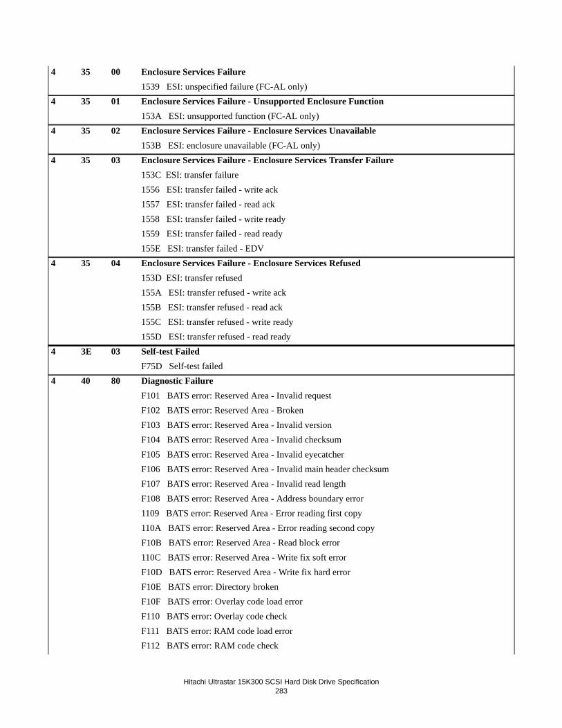
Hitachi Ultrastar 15K300 SCSI Hard Disk Drive Specification
283
4 35 00 Enclosure Services Failure1539 ESI: unspecified failure (FC-AL only)
4 35 01 Enclosure Services Failure - Unsupported Enclosure Function153A ESI: unsupported function (FC-AL only)
4 35 02 Enclosure Services Failure - Enclosure Services Unavailable153B ESI: enclosure unavailable (FC-AL only)
4 35 03 Enclosure Services Failure - Enclosure Services Transfer Failure153C ESI: transfer failure1556 ESI: transfer failed - write ack1557 ESI: transfer failed - read ack1558 ESI: transfer failed - write ready1559 ESI: transfer failed - read ready155E ESI: transfer failed - EDV
4 35 04 Enclosure Services Failure - Enclosure Services Refused153D ESI: transfer refused155A ESI: transfer refused - write ack155B ESI: transfer refused - read ack155C ESI: transfer refused - write ready155D ESI: transfer refused - read ready
4 3E 03 Self-test FailedF75D Self-test failed
4 40 80 Diagnostic FailureF101 BATS error: Reserved Area - Invalid requestF102 BATS error: Reserved Area - BrokenF103 BATS error: Reserved Area - Invalid versionF104 BATS error: Reserved Area - Invalid checksumF105 BATS error: Reserved Area - Invalid eyecatcherF106 BATS error: Reserved Area - Invalid main header checksumF107 BATS error: Reserved Area - Invalid read lengthF108 BATS error: Reserved Area - Address boundary error1109 BATS error: Reserved Area - Error reading first copy110A BATS error: Reserved Area - Error reading second copyF10B BATS error: Reserved Area - Read block error110C BATS error: Reserved Area - Write fix soft errorF10D BATS error: Reserved Area - Write fix hard errorF10E BATS error: Directory brokenF10F BATS error: Overlay code load errorF110 BATS error: Overlay code checkF111 BATS error: RAM code load errorF112 BATS error: RAM code check

Hitachi Ultrastar 15K300 SCSI Hard Disk Drive Specification
284
F113 BATS error: Config invalidF114 BATS error: Log manager invalidF115 BATS error: Media tables invalidF116 BATS error: Logical-to-physical invalidF117 BATS error: Defect manager invalidF11D Incorrect Disk CodeF11F RPO SID invalidF120 BATS error: Code compatibility failureF121 BATS error: Code download in progressF122 BATS error: Performance data read errorF125 BATS error: Invalid RID/FIDF126 BATS error: Code checksum errorF127 BATS error: Invalid headerF12B BATS error: Reserved area - invalid modelF12C BATS error: Invalid code sizeF12D Format Reserved: FAT size exceededF12E Format Reserved: Insufficient DIRS goodF12F Format Reserved: Insufficient FATS goodF130 Incorrect Customer codeF131 Flash timeout
4 40 90 Diagnostic FailureF118 BATS#2 error: Seek test error
4 40 A0 Diagnostic FailureF119 BATS#2 error: Read/write test errorF11A BATS#2 error: ECC test errorF11B BATS#2 error: CRC test errorF11C BATS#2 error: XOR test error
4 44 00 Internal Target FailureF203 Internal target failureF207 AHB Access ErrorF302 Motor: Unrecovered internal errorF304 Motor: Unrecovered Open Loop Commutation errorF306 Motor: Unrecovered No feedback detected errorF308 Motor: Unrecovered Settle timeoutF30A Motor: Unrecovered Gross speed errorF30C Motor: Unrecovered 12V OK errorF30E Motor: Unrecovered Speed errorF312 Motor: Unrecovered internal 12V not OK timeoutF446 Servo: Unrecovered DFT Sharp errorF448 Servo: Unrecovered Load/Unload state error

Hitachi Ultrastar 15K300 SCSI Hard Disk Drive Specification
285
1449 Servo: Recovered TFCR out-of-range errorF44A Servo: Unrecovered TFCR out-of-range errorF314 Motor: Unrecovered Inductive Sense measurment timeoutF316 Motor: Unrecovered Spin Sense speed errorF31A Motor: Unrecovered Target speed errorF31C Motor: Unrecovered Power driver version errorF31E Motor: Unrecovered Over current errorF322 Motor Unrecovered Negative regulator faultF324 Motor Unrecovered Module overtemp errorF326 Motor Unrecovered 12V or 5V OK errorF328 Motor: Unrecovered unkown errorF402 Servo: Unrecovered Requested re zero head does not existF404 Servo: Unrecovered Back EMF movement in progressF406 Servo: Unrecovered Back EMF timeout errorF408 Servo: Unrecovered ADC conversion timeoutF40A Servo: Unrecovered Load/unload calibration errorF40C Servo: Unrecovered Invalid 5 voltsF40E Servo: Unrecovered Invalid 12 voltsF410 Servo: Unrecovered Invalid harmonic requestedF412 Servo: Unrecovered Gain BEMF Calibration errorF414 Servo: Unrecovered VOFF BEMF calibration errorF416 Servo: Unrecovered Invalid temperatureF418 Servo: Unrecovered Truncated rezeroF41A Servo: Unrecovered Heads not loadedF426 Servo: Unrecovered KT Seek out of rangeF428 Servo: Unrecovered DAC Offset calibration errorF42A Servo: Unrecovered Load speed errorF42E Servo: Unrecovered ADC Calibration errorF430 Servo: Unrecovered ADC Offset errorF432 Servo: Unrecovered ADC Limit errorF434 Servo: Unrecovered Balancer Resistance errorF436 Servo: Unrecovered Balancer Resistance Limit errorF438 Servo: Unrecovered First Cylinder errorF43A Servo: Unrecovered Valid Cylinder errorF43C Servo: Unrecovered ADC Saturation errorF43E Servo: Unrecovered Latch Break timeoutF440 Servo: Unrecovered MR Resistance out of range errorF442 Servo: Servo: Unrecovered VCM Retract errorF444 Servo: Unrecovered Load Retry errorF446 Servo Unrecovered DFT Sharp error

Hitachi Ultrastar 15K300 SCSI Hard Disk Drive Specification
286
F448 Servo Unrecovered Load/Unload state errorF44A Servo Unrecovered TCFR out-of-range errorF603 Channel/AE target failureF604 Channel/AE calibration errorF607 Unrecovered data with PPM or precomp loadF609 Unrecovered data with TA detectionF60B Unrecovered with SMM or VM or DDFF60D Unrecovered data pre-PPM or FH detectionF60F Unrecovered data write or pre-TA detectionF611 Unrecovered data with pre-SMM or VM or STM or DDFF613 Unrecovered data with NRZ parity errorF615 Unrecovered parity PP correction or STWF617 Unrecovered channel errorF619 Unrecovered AE thermal asperity foundF61B Unrecovered AE open MR element errorF61D Unrecovered AE IC over temperature errorF61F Unrecovered AE IP clock count errorF621 Unrecovered AE high MR current errorF623 Unrecovered AE write data BLS errorF625 Unrecovered AE invalud head address errorF627 Unrecovered AE power supply errorF629 Unrecovered AE open write head errorF62B Unrecovered AE write transition errorF62D Unrecovered AE no write head current error F62F Unrecovered Channel Pre-TA errorF631 Unrecovered Channel write or NRZ parity errorF633 Unrecovered Channel write synch unlock errorF635 Unrecovered AE Short write read head errorF637 Unrecovered AE Short write head errorF639 Unrecovered AE Non-selected write head errorF63B Unrecovered AE Write current in read errorF63D Unrecovered AE IH open short errorF63F Unrecovered AE IH delay errorF641 Unrecovered Channel coarse tune timeout errorF643 Unrecovered AE Readback errorF645 Unrecovered Channel coarse tune timeout errorF713 Unrecovered ECC errorF717 Unrecovered overrunF71B Unrecovered ECC overrunF71D Unrecovered DRAM CRC error

Hitachi Ultrastar 15K300 SCSI Hard Disk Drive Specification
287
F71F Unrecovered ID Parity errorF732 Unrecovered Write FaultF75A Unknown unrecovered errorF799 Unrecovered ID not found errorF7B5 Unrecovered Shock sensor errorF7B9 Unrecovered Reference tag errorF7BB Unrecovered Application tag errorF7BD Unrecovered Channel write synthesis unlock errorF7C1 Unrecovered End sector check errorF7C3 Unrecovered Read CRC errorF7C5 Unrecovered DRAM ECC errorF7C7 Unrecovered DRAM ECC LBA errorF7C9 Unrecovered DRAM ECC Write errorFCxx Unable to read RID or FID number xx
4 44 0B Vendor Unique - Internal Target FailureF310 Motor: Unrecovered Spindle Current errorF318 Motor: Unrecovered Spin Sense timeoutF320 Motor: Unrecovered System clock watchdog errorF32A Motor: Unrecovered VCM DAC watchdog error
4 44 F2 Vendor Unique - Internal Target FailureF134 Head Health Check data compare error
4 44 F6 Vendor Unique - Internal Target FailureF135 Head Health Check unrecovered media error
4 81 00 Vendor Unique - Internal Logic ErrorF602 Channel/AE hard logic errorF56E Log dump data corruptF56F Log dump data memory error Sense Key = Illegal Request
5 1A 00 Parameter List Length Error1509 Parameter list length error
5 20 00 Invalid Command Operation Code150A Invalid opcode in CDB
5 21 00 Logical Block Address out of Range150B LBA out of range
5 24 00 Invalid Field in CDB150C Illegal request - invalid field in CDB1542 SPC buffer not allocated
5 24 F3 Vendor Unique - Illegal Request1545 Formatted without P-List
5 25 00 Logical Unit Not Supported

Hitachi Ultrastar 15K300 SCSI Hard Disk Drive Specification
288
150D Invalid LUN5 26 00 Invalid Field in Parameter List
150E Illegal request - invalid field in parameter list150F Saved parameter not supported1510 Unsupported log page
5 26 04 Invalid Release of Active Persistent Reservation1540 Invalid release of persistent reservation
5 35 01 Unsupported Enclosure Function1511 Unsupported enclosure services function (FC-AL only)
5 49 00 Invalid Message Error1512 Invalid message (SCSI only)
5 55 00 System Buffer Full1513 System buffer full
5 55 04 Insufficient Registration Resources1567 Insufficient registration resources Sense Key = Unit Attention
6 28 00 Not Ready To Ready Transition (Format completed)1514 Not ready to read transition
6 29 00 Unit Attention - Login Reset1515 Login reset (FC-AL only)
6 29 01 Unit Attention - POR Occurred1516 Power on reset
6 29 02 Unit Attention - SCSI Bus Reset Occurred1517 SCSI bus reset (SCSI), LIP Reset (FC-AL), SAS Hard Reset (SAS)
6 29 03 Unit Attention - Bus Device Reset Occurred1518 Bus device reset (SCSI only), Target Reset (FC-AL), LUN Reset (SAS)
6 29 04 Unit Attention - Self Initiated Reset Occurred1519 Self initiated reset
6 29 05 Transceiver Changed to SE151A Tranceiver changed to single-ended (SCSI only)1548 Hard Reset received
6 29 06 Transceiver Changed to LVD151B Tranceiver changed to LVD (SCSI only)
6 29 07 I_T Nexus Loss Occurred1554 I_T Nexus Loss Occurred (SAS only)
6 2A 01 Mode Parameters Changed151C Mode parameters changed
6 2A 02 Log Parameters Changed151D Log parameters changed
6 2A 03 Reservations Preempted

Hitachi Ultrastar 15K300 SCSI Hard Disk Drive Specification
289
151E Reservations pre-empted6 2A 04 Reservations Released
151F Reservations released6 2A 05 Registrations Released
1520 Registrations pre-empted6 2F 00 Commands Cleared by Another Initiator
1521 Commands cleared by another initiator6 2F 01 Commands Cleared by Power Loss Notification
1573 Commands cleared due to power failure event (SAS)6 3F 01 Microcode has been changed
1522 Microcode changed6 3F 03 Inquiry Parameters Changed
1523 Inquiry parameters changed6 3F 05 Device Identifier Changed
1537 Device identifier changed6 5D 00 Predictive Failure Analysis Threshold Reached
1524 PFA Threshold reached6 5D FF Predictive Failure Analysis Threshold Reached
1525 PFA Test warning Sense Key = Aborted Command
B 1B 00 Synchronous Data Transfer Error1527 Synchronous data transfer error (SCSI only)1528 ACK synchronization error (SCSI only)
B 0E 00 Information Unit Too Long1562 Information unit too long.
B 25 00 Logical Unit Not Supported1529 Unsupported LUN (SCSI only)
B 3F 0F Aborted Command - Echo Buffer Overwritten1544 Echo buffer overwritten
B 43 00 Message Error152A Message reject error (SCSI only)152C Message parity error rcvd when no message sent by target (SCSI only)
B 44 00 Internal Target Failure152D Buffer CRC error on read152E Internal target failure - Host Interface154A Xfer Ready credit exceeded (FC-AL only)154B Xfer length error (FC-AL only)1568 End-to-End Data Protection Guard check1569 End-to-End Data Protection Application Tag check156A End-to-End Data Reference Tag check

Hitachi Ultrastar 15K300 SCSI Hard Disk Drive Specification
290
156B ECC error in DRAM customer data area156C Uncorrectable DRAM ECC error1570 Host interface CRC errorF645 Unrecovered Channel coarse tune timeoutF75C Internal media access timeoutF761 Read/write command timeoutF772 DASH starting timeoutF773 ID table timeoutF774 Servo timeoutF775 Buffers timeoutF776 DASH done timeoutF777 DASH unknown timeoutF77A Unrecovered Channel SBW timeoutF77D Recovery timeoutF7B1 Overall command timeoutF7D0 Pre-load timeout17E0 Servo: Recovered read/write abort estimator errorF7E1 Servo: Unrecovered read/write abort estimator error17E2 Servo: Recovered read/write abort predictor errorF7E3 Servo: Unrecovered read/write abort predictor error17E4 Servo: Recovered read/write abort PES errorF7E5 Servo: Unrecovered read/write abort PES error17E6 Servoe: Recovered read/write abort seek start errorF7E7 Servo: Unrecovered read/write abort seek start error17E8 Servo: Recovered read/write abort PES reset errorF7E9 Servo: Recovered read/write abort PES reset error17EA Servo: Recovered read/write abort SID unlock errorF7EB Servo: Unrecovered read/write abort SID unlock error17EC Servo: Recovered read/write abort WCS other errorF7ED Servo: Unrecovered read/write abort WCS other error17EE Servo: Recovered read/write abort hard resetF7EF Servo: Unrecovered read/write abort hard reset17F0 Servo: Recovered read/write abort RV sensor errorF7F1 Servo: Unrecovered read/write abort RV sensor error17F2 Servo: Recovered read/write abort RV sensor errorF7F3 Servo: Unrecovered read/write abort RV sensor error17F4 Servo: Recovered read/write abort SHARP other errorF7F5 Servo: Unrecovered read/write abort SHARP other error17F6 Servo: Recovered read/write abort SHARP exception errorF7F7 Servo: Unrecovered read/write abort SHARP exception error

Hitachi Ultrastar 15K300 SCSI Hard Disk Drive Specification
291
17F8 Servo: Recovered read/write abort SVGA limit errorF7F9 Servo: Unrecovered read/write abort SVGA limit error17FA Servo: Recovered read/write abort gray code errorF7FB Servo: Unrecovered read/write abort gray code error17FC Servo: Recovered read/write abort burst errorF7FD Servo: Unrecovered read/write abort burst error17FE Servo: Recovered read/write abort no STM errorF7FF Servo: Unrecovered read/write abort no STM error
B 45 00 Select or Reselect Failure152F Selection reselection error (SCSI only)
B 47 00 SCSI Parity Error1530 Message parity error - initiator (SCSI only)1531 Message parity error - target (SCSI only)
B 47 03 Information Unit iuCRC Error Detected1543 IU SCSI CRC error
B 48 00 Initiator Detected Error Message Received1532 Initiator detected error message received (SCSI only)
B 49 00 Invalid Message Error152B Attention dropped too late (SCSI only)1533 Inappropriate or illegal message (SCSI only)
B 4B 00 Data Phase Error153E Data phase error
B 4B 01 Invaled Target Port Transfer Tag Received1561 Information unit too short (SAS only)
B 4B 02 Too Much Write Data1560 Too much write data (SAS only)
B 4B 03 ACK/NAK Timeout1551 ACK/NAK Timeout (SAS only)
B 4B 04 NAK Received1550 NAK Received (SAS only)
B 4B 05 Data Offset Error1552 Bad parameter offset (SAS only)
B 4B 06 Initiator Response Timeout1555 Initiator response timeout (SAS only)
B 0E 00 Information Unit Too Long1562 Information unit too long.
B 4E 00 Overlapped Commands Attempted1534 Overlapped command attempted
B 4F 00 Command Aborted Due To Loop Initialization153F Abort by LIP (FC-AL only), Abort by OOB (SAS)
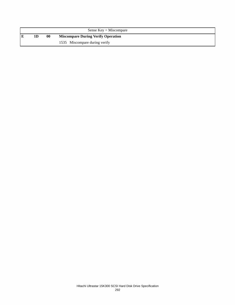
Hitachi Ultrastar 15K300 SCSI Hard Disk Drive Specification
292
Sense Key = MiscompareE 1D 00 Miscompare During Verify Operation
1535 Miscompare during verify

Hitachi Ultrastar 15K300 SCSI Hard Disk Drive Specification
293
21.2.9 RU: Field Replaceable Unit (Byte 14)The FRU (Field Replaceable Unit) field value will always be zero.
21.2.10 Sense Key Specific (Byte 15 through 17)The definition of this field is determined by the value of the sense key field.
21.2.10.1 Sense Key Specific - Illegal Request (Sense Key = 5h)Error field pointer is returned.
Table 199: Field Pointer Bytes
SKSV Sense-key specific valid
0 Sense-key specific field is not valid.
1 Sense-key specific field is valid.
C/D Command/Data
0 Indicates that the illegal parameter was in the data parameters sent by the initiator during DATA OUT phase
1 Indicates that the illegal parameter was in the command descriptor block.
BPV Bit Pointer Valid
0 Bit pointer field is not valid.
1 Bit pointer field is significant.
Bit Pointer Indicates which bit of the byte number reported in Field Pointer is the bit in error. When a multiple bit field is in error, the pointer points to the most significant bit of the field.
Field Pointer Indicates which bytes of the command descriptor block or of the parameter data were in error. Bytes are numbered starting from zero, as shown in the tables describing the commands and parameters. When a mul-tiple byte field id is in error, the pointer points to the most significant byte of that field.
ByteBit
7 6 5 4 3 2 1 0
15 SKSV C/D Reserved BPV Bit Pointer
16
17
(MSB) Field Pointer
(LSB)

Hitachi Ultrastar 15K300 SCSI Hard Disk Drive Specification
294
21.2.10.2 Sense Key Specific - Recovered (Sense Key = 1h) or Medium (Sense Key = 3h) or Hard-ware (Sense Key =4h)
Hardware (Sense Key = 4h) or Medium Error (Sense Key = 3h)
Actual Retry Count is reported.
Table 200: Actual Retry Count
SKSV Sense-key specific valid
0 Actual Retry Count is not valid.
1 Actual Retry Count is valid.
Actual Retry Count Number of retry steps used in attempting to recover from the error condition.
The content of these two bytes indicates:
0x04nn - nn recovery steps were used in the 'Minus Mod' branch of the recovery process,
0x02nn - nn recovery steps were used in the 'TA' branch of the recovery process,
0x01nn - nn recovery steps were used in the 'Sync Byte' branch of the recovery process.
Secondary Step Secondary error recovery step (valid for servo errors only).
ERP Type Error recovery table branch for this error. Valid values are shown in the table below.
21.2.10.3 Sense Key Specific - Not Ready (Sense key = 2h)These fields are defined for the Format unit (04h) command with the Immediate bit set to one and the Send Diagnostic (1Dh) command with Background self-test function.
ByteBit
7 6 5 4 3 2 1 0
15 SKSV Reserved
16 Secondary Step ERP Type
17 Actual Retry Count
Recovery Type ERP TypeRead 0x00Verify 0x01Write 0x02Seek 0x03Read, Sync Byte branch 0x04Read, Thermal Asperity branch 0x05Read, Minus Mod branch 0x06Verify, Sync Byte branch 0x07Verify, Thermal Asperity branch 0x08Verify, Minus Mod branch 0x09

Hitachi Ultrastar 15K300 SCSI Hard Disk Drive Specification
295
Progress indication is returned.
Table 201: Progress Indication
SKSV Sense-key specific valid
0 Progress Indication is not valid.
1 Progress Indication is valid.
Progress Indication Indicates a percent complete in which the returned value is the numerator that has 10000h as its denominator.
21.2.11 Reserved (Byte 18 through 19)Reserved fields are filled with zero.
21.2.12 Vendor unique error information (Byte 20 through 23)This field gives detailed information about the error. It contains a unique code which describes where the error was detected and which piece of hardware or microcode detected the error depending on current operation.
21.2.13 Physical Error Record (Byte 24 thru 29)• ILI = 1 - This field contains zeros.
• ILI = 0 - These bytes contain the physical location of the error in cylinder, head, and sector. Bytes 24, 25, and 26 are cylinder high, middle and low bytes respectively, of the cylinder number. Byte 27 is the head number. Bytes 28 and 29 are the high and low bytes, respectively of the sector number.
If the head is undetermined, bytes 24, 25, and 26 are set to 0FFFFFFh. If the head number is undetermined, byte 27 is set to 0FFh. If cylinder, head, and sector have no relevance the error, bytes 24 through 29 will all be set to 0FFFFFFFFFFFFh for Valid = 0 and ILI = 0. This Physical Error Record field is valid for Sense Key 1, 3, and 4 only.
21.2.14 Reserved (Byte 30 through 31)Reserved fields are filled with zero.
ByteBit
7 6 5 4 3 2 1 0
15 SKSV Reserved
16
17
(MSB) Progress Indication
(LSB)
Valid ILI Description
1 0 Cylinder Number (bytes 24-26)Head number (byte 27)Sector Number (bytes 28-29)
1 1 0x000000000000
0 x 0x000000000000 - (not used/invalid)

Hitachi Ultrastar 15K300 SCSI Hard Disk Drive Specification
296

Hitachi Ultrastar 15K300 SCSI Hard Disk Drive Specification297
22.0 Appendix. UEC listFollowing is the list of Unit Error Codes and associated descriptions. The Unit Error Codes are returned by the target in sense data bytes 20-21.
The list of Unit Error Codes and descriptions does not have a direct correlation to the error descriptions and Sense Key/Code/Qualifier descriptions in Section 21.0, “SCSI Sense Data” on page 271. These codes are used internally by Hitachi and may change without notice.
How to find a specific UECThe first hex digit of the UEC indicates the error severity, e.g. Fxxx codes are for hard/unrecoverable errors, 1xxx codes are for soft/recoverable errors, etc. The second hex digit indicates the grouping, e.g. interface, media, servo, etc. types of errors. The table is sorted without regard to the first hex digit; instead, sorting is by the least significant three hex digits. Unit Error Codes list.
Table 202: Unit Error Codes list
UEC Description---- ---------------------------------------------------------0000 No errorF101 BATS error: Reserved Area - Invalid requestF102 BATS error: Reserved Area - BrokenF103 BATS error: Reserved Area - Invalid versionF104 BATS error: Reserved Area - Invalid checksumF105 BATS error: Reserved Area - Invalid eyecatcherF106 BATS error: Reserved Area - Invalid main header checksumF107 BATS error: Reserved Area - Invalid read lengthF108 BATS error: Reserved Area - Address boundary error1109 BATS error: Reserved Area - Error reading first copy110A BATS error: Reserved Area - Error reading second copyF10B BATS error: Reserved Area - Read block error110C BATS error: Reserved Area - Write fix soft errorF10D BATS error: Reserved Area - Write fix hard errorF10E BATS error: Directory brokenF10F BATS error: Overlay code load errorF110 BATS error: Overlay code checkF111 BATS error: RAM code load errorF112 BATS error: RAM code checkF113 BATS error: Config invalidF114 BATS error: Log manager invalidF115 BATS error: Media tables invalidF116 BATS error: Logical-to-physical invalidF117 BATS error: Defect manager invalidF118 BATS#2 error: Seek test errorF119 BATS#2 error: Read/write test error

Hitachi Ultrastar 15K300 SCSI Hard Disk Drive Specification298
F11A BATS#2 error: ECC test errorF11B BATS#2 error: CRC test errorF11C BATS#2 error: XOR test errorF11D Incorrect Disk CodeF11F RPO SID invalidF120 BATS error: Code Compatibility FailureF121 BATS error: Code download in progressF122 BATS error: Performance data read errorF123 Invalid request to enter sleep modeF124 Bring-up errorF125 BATS error: Invalid RID/FIDF126 BATS error: Code checksum errorF127 BATS error: Invalid headerF128 DRAM test in progressF129 DRAM test completeF12A DRAM test errorF12B BATS error: Reserved area - invalid modelF12C BATS error: Invalid code sizeF130 Incorrect Customer CodeF131 Flash timeoutF132 GEM FH track read errorF133 BATS error: Vendor ID mismatchF134 Head Health Check data compare errorF135 Head Health Check unrecovered media errorF136 BATS#2 error: End-To-End Data Protection error
1201 Error in UEC class1202 Error in UEC causeF203 Internal target failureF204 Reassign reserved area media errorF205 G-list full - can't reassign any more sectorsF206 No spares availableF207 AHB Access Error
1301 Motor: Recovered internal errorF302 Motor: Unrecovered internal error1303 Motor: Recovered Open Loop Commutation failureF304 Motor: Unrecovered Open Loop Commutation failure1305 Motor: Recovered No feedback detected errorF306 Motor: Unrecovered No feedback detected error1307 Motor: Recovered Settle timeout
UEC Description

Hitachi Ultrastar 15K300 SCSI Hard Disk Drive Specification299
F308 Motor: Unrecovered Settle timeout1309 Motor: Recovered Gross speed errorF30A Motor: Unrecovered Gross speed error130B Motor: Recovered 12V OK errorF30C Motor: Unrecovered 12V OK error130D Motor: Recovered Speed errorF30E Motor: Unrecovered Speed error130F Motor: Recovered Spindle Current errorF310 Motor: Unrecovered Spindle Current error1311 Moto: Recovered Internal 12V not OK timeoutF312 Motor: Unrecovered Internal 12V not OK timeout1313 Motor: Recovered Inductive Sense measurement timeoutF314 Motor: Unrecovered Inductive Sense speed errorF315 Motor: Recovered Spin Sense speed errorF316 Motor: Unrecovered Spin Sense speed error1317 Motor: Recovered Spin Sense timeoutF318 Motor: Unrecovered Spin Sense timeout1319 Motor: Recovered Target speed errorF31A Motor: Unrecovered Target speed error131B Motor: Recovered Power driver version errorF31C Motor: Unrecovered Power driver version error131D Motor: Recovered Over current errorF31E Motor: Unrecovered Over current error131F Motor: Recovered System clock watchdog errorF320 Motor: Unrecovered System clock watchdog error1321 Motor: Recovered Negative regulator faultF322 Motor: Unrecovered Negative regulator fault1323 Motor: Recovered Module overtemp errorF324 Motor: Unrecovered Module overtemp error1325 Motor: Recovered 12V or 5V OK errorF326 Motor: Unrecovered 12V or 5V OK error1327 Motor: Recovered unknown errorF328 Motor: Unrecovered unknown error1329 Motor: Recovered VCM DAC watchdog errorF32A Motor: Unrecovered VCM DAC watchdog error
1401 Servo: Recovered Requested rezero head does not existF402 Servo: Unrecovered Requested rezero head does not exist1403 Servo: Recovered Back EMF movement in progressF404 Servo: Unrecovered Back EMF movement in progress1405 Servo: Recovered Back EMF timeout error
UEC Description

Hitachi Ultrastar 15K300 SCSI Hard Disk Drive Specification300
F406 Servo: Unrecovered Back EMF timeout error1407 Servo: Recovered ADC conversion timeoutF408 Servo: Unrecovered ADC conversion timeout1409 Servo: Recovered Load/unload calibration errorF40A Servo: Unrecovered Load/unload calibration error140B Servo: Recovered Invalid 5 voltsF40C Servo: Unrecovered Invalid 5 volts140D Servo: Recovered Invalid 12 voltsF40E Servo: Unrecovered Invalid 12 volts140F Servo: Recovered Invalid harmonic requestedF410 Servo: Unrecovered Invalid harmonic requested1411 Servo: Recovered Gain BEMF Calibration errorF412 Servo: Unrecovered Gain BEMF Calibration error1413 Servo: Recovered VOFF BEMF calibration errorF414 Servo: Unrecovered VOFF BEMF calibration error1415 Servo: Recovered Invalid temperatureF416 Servo: Unrecovered Invalid temperature1417 Servo: Recovered Truncated rezeroF418 Servo: Unrecovered Truncated rezero1419 Servo: Recovered Heads not loadedF41A Servo: Unrecovered Heads not loaded141B Servo: Recovered No seek completeF41C Servo: Unrecovered No seek complete141D Servo: Recovered Seek timeoutF41E Servo: Unrecovered Seek timeout141F Servo: Recovered Seek errorF420 Servo: Unrecovered Seek error1421 Servo: Recovered Track following errorF422 Servo: Unrecovered Track following error1423 Servo: Recovered Track follow timeoutF424 Servo: Unrecovered Track follow timeout1425 Servo: Recovered KT Seek out of rangeF426 Servo: Unrecovered KT Seek out of range1427 Servo: Recovered DAC Offset calibration errorF428 Servo: Unrecovered DAC Offset calibration error1429 Servo: Recovered Load speed errorF42A Servo: Unrecovered Load speed error142B Servo: Recovered RRO Calibration timeoutF42C Servo: Unrecovered RRO Calibration timeout142D Servo: Recovered ADC Calibration errorF42E Servo: Unrecovered ADC Calibration error
UEC Description

Hitachi Ultrastar 15K300 SCSI Hard Disk Drive Specification301
142F Servo: Recovered ADC Offset errorF430 Servo: Unrecovered ADC Offset error1431 Servo: Recovered ADC Limit errorF432 Servo: Unrecovered ADC Limit error1433 Servo: Recovered Balancer Resistance errorF434 Servo: Unrecovered Balancer Resistance error1435 Servo: Recovered Balancer Resistance Limit errorF436 Servo: Unrecovered Balancer Resistance Limit error1437 Servo: Recovered First Cylinder errorF438 Servo: Unrecovered First Cylinder error1439 Servo: Recovered Valid Cylinder errorF43A Servo: Unrecovered Valid Cylinder error143B Servo: Recovered ADC Saturation errorF43C Servo: Unrecovered ADC Saturation error143D Servo: Recovered Latch Break timeoutF43E Servo: Unrecovered Latch Break timeout143F Servo: Recovered MR Resistance out of range errorF440 Servo: Unrecovered MR Resistance out of range error1441 Servo: Recovered VCM Retract errorF442 Servo: Unrecovered VCM Retract error1443 Servo: Recovered Load Retry errorF444 Servo: Unrecovered Load Retry error1445 Servo: Recovered DFT Sharp errorF446 Servo: Unrecovered DFT Sharp error1447 Servo: Recovered Load/Unload state errorF448 Servo: Unrecovered Load/Unload state error1449 Servo: Recovered TFCR out-of-range errorF44A Servo: Unrecovered TFCR out-of-range error
1501 Logical unit not ready1502 Logical unit becoming ready1503 Logical unit not ready - initializing command required1504 Not ready - format in progress1505 Not ready - self-test in progress1506 Reassign failed1507 Format failed1509 Parameter list length error150A Invalid opcode in CDB150B LBA out of range150C Illegal request - invalid field in CDB150D Invalid LUN
UEC Description

Hitachi Ultrastar 15K300 SCSI Hard Disk Drive Specification302
150E Illegal request - invalid field in parameter list150F Saved parameter not supported1510 Unsupported log page1511 Unsupported enclosure services function (FC-AL only)1512 Invalid message (SCSI only)1513 System buffer full1514 Not ready to ready transition1515 Login reset (FC-AL only)1516 Power on reset1517 SCSI bus reset (SCSI), LIP reset (FC-AL), SAS Hard Reset (SAS)1518 Bus device reset (SCSI), Target Reset (FC-AL), LUN Reset (SAS)1519 Self initiated reset151A Tranceiver changed to single-ended (SCSI only)151B Tranceiver changed to LVD (SCSI only)151C Mode parameters changed151D Log parameters changed151E Reservations pre-empted151F Reservations released1520 Registrations pre-empted1521 Commands cleared by another initiator1522 Microcode changed1523 Inquiry parameters changed1524 PFA threshold reached1525 PFA test warning1527 Synchronous data transfer error (SCSI only)1528 ACK synchronization error (SCSI only)1529 Unsupported LUN (SCSI only)152A Message reject error (SCSI only)152B Attention dropped too late (SCSI only)152C Message parity error rcvd when no message sent by target (SCSI only)152D Buffer CRC error on read152E Internal target failure152F Selection reselection error (SCSI only)1530 Message parity error - initiator (SCSI only)1531 Message parity error - target (SCSI only)1532 Initiator detected error message received (SCSI only)1533 Inappropriate or illegal message (SCSI only)1534 Overlapped command attempted1535 Miscompare during verify1536 Reservation conflict1537 Device identifier changed
UEC Description

Hitachi Ultrastar 15K300 SCSI Hard Disk Drive Specification303
1539 ESI: unspecified failure (FC-AL only)153A ESI: unsupported function (FC-AL only)153B ESI: enclosure unavailable (FC-AL only)153C ESI: transfer failure (FC-AL only)153D ESI: tranfer refused (FC-AL only)153E Data phase error153F Abort by LIP (FC-AL), Abort by OOB (SAS)1540 Invalid release of persistent reservation1541 Low power condition on1542 SPC buffer not allocated1543 IU SCSI CRC error1544 Echo buffer overwritten1545 Formatted with No P-List1548 Hard Reset received154A Xfer Ready credit exceeded (FC-AL only)154B Transfer length error (FC-AL only)1550 NAK rcvd (SAS)1551 ACK NAK Timeout (SAS)1552 Bad parameter offset (SAS)1553 LUN Not ready, Notify (Enable Spinup) required (SAS)1554 I_T_Nexus Loss Occurred (SAS)1555 Initiator Response Timeout (SAS)1556 ESI transfer failed - write ack (FC-AL)1557 ESI transfer failed - read ack (FC-AL)1558 ESI transfer failed - write ready (FC-AL)1559 ESI transfer failed - read ready (FC-AL)155A ESI transfer refused - write ack (FC-AL)155B ESI transfer refused - read ack (FC-AL)155C ESI transfer refused - write ready (FC-AL)155D ESI transfer refused - read ready (FC-AL)155E ESI transfer failed - EDV (FC-AL)1560 Too much write data (SAS)1561 Information unit too short (SAS)1562 Information unit too long (SAS)1567 Insufficient registration resources1568 End-to-End Data Protection Guard check1569 End-to-End Data Protection Application Tag check156A End-to-End Data Protection Reference Tag check156B ECC error in DRAM customer data area156C Uncorrectable DRAM ECC errorF56C Log dump data corrupt
UEC Description

Hitachi Ultrastar 15K300 SCSI Hard Disk Drive Specification304
F56F Log dump data memory error1570 Host interface CRC error1572 LUN not ready; manual intervention required1573 Commands cleared due to power failure event (SAS)
1601 Channel/AE internal logic errorF602 Channel/AE hard logic errorF603 Channel/AE target failureF604 Channel/AE calibration error1606 Recovered data with PPM or precomp loadF607 Unrecovered data with PPM or precomp load1608 Recovered data with TA (Thermal Asperity) detectionF609 Unrecovered data with TA detection160A Recovered data with SMM or VM or DDFF60B Unrecovered data with SMM or VM or DDF160C Recovered data with pre-PPM or FH (Fly Height) detectionF60D Unrecovered data with pre-PPM or FH detection160E Recovered data with write or pre-TA detectionF60F Unrecovered data with write or pre-TA detection1610 Recovered data with pre-SMM or VM or STM or DDFF611 Unrecovered data with pre-SMM or VM or STM or DDF1612 Recovered data with NRZ parity errorF613 Unrecovered data with NRZ parity error1614 Recovered parity PP correction or STWF615 Unrecovered parity PP correction or STW1616 Recovered channel errorF617 Unrecovered channel error1618 Recovered AE thermal asperity foundF619 Unrecovered AE thermal asperity found161A Recovered AE open MR element errorF61B Unrecovered AE open MR element error161C Recovered AE IC over temperature errorF61D Unrecovered AE IC over temperature error161E Recovered AE IP clock count errorF61F Unrecovered AE IP clock count error1620 Recovered AE high MR current errorF621 Unrecovered AE high MR current error1622 Recovered AE write data BLS errorF623 Unrecovered AE write data BLS error1624 Recovered AE invalid head address errorF625 Unrecovered AE invalid head address error
UEC Description

Hitachi Ultrastar 15K300 SCSI Hard Disk Drive Specification305
1626 Recovered AE power supply errorF627 Unrecovered AE power supply errorF629 Unrecovered AE open write head error162A Recovered AE write transition errorF62B Unrecovered AE write transition error162C Recovered AE no write head current errorF62D Unrecovered AE no write head current error162E Recovered Channel Pre-TA errorF62F Unrecovered Channel Pre-TA error1630 Recovered Channel write or NRZ parity errorF631 Unrecovered Channel write or NRZ parity error1632 Recovered Channel Write Synth Unlock errorF633 Unrecovered Channel Write Synth Unlock error1634 Recovered AE Short write read head errorF635 Unrecovered AE Short write read head error1636 Recovered AE Short write head errorF637 Unrecovered AE Short write head error1638 Recovered AE Non-selected write head errorF639 Unrecovered AE Non-selected write head error163A Recovered AE Write current in read errorF63B Unrecovered AE Write current in read error163C Recovered AE IH Open short errorF63D Unrecovered AE IH Open short error163E Recovered AE IH Deleay errorF63F Unrecovered AE IH Deleay error1640 Recovered AE Write head encode errorF641 Unrecovered AE Write head encode error1642 Recovered AE Readback errorF643 Unrecovered AE Readback error1644 Recovered Channel coarse tune timeoutF645 Unrecovered Channel coarse tune timeout
F701 Format corruptedF702 Too many notchesD703 Auto-reallocated due to write error1704 Recommend reassign due to write errorE705 Media error with OTF correction - reassignedE706 Media error with OTF correction - recommend reassignE707 Media error with OTF correction - recommend rewriteD708 Media error with OTF correction - rewritten1709 Media error with offline correction
UEC Description

Hitachi Ultrastar 15K300 SCSI Hard Disk Drive Specification306
D70A Media error with offline correction - reassignedE70B Media error with offline correction - recommend reassignE70C Media error with offline correction - recommend rewriteE70D Media error with offline correction - rewrittenE70E Recovered Data Address Mark error - rewrittenE70F Recovered Data Address Mark error - recommend rewriteD710 Recovered Data Address Mark error - reassignedE711 Recovered Data Address Mark error - recommend reassign1712 Recovered ECC errorF713 Unrecovered ECC error1714 Recovered sector overflowF715 Unrecovered sector overflow1716 Recovered overrunF717 Unrecovered overrun1718 Recovered abort immediateF719 Unrecovered abort immediate171A Recovered ECC overrunF71B Unrecovered ECC overrun17B8 Recovered Reference tag error171C Recovered DRAM CRC errorF71D Unrecovered DRAM CRC error171E Recovered ID Parity errorF71F Unrecovered ID Parity error1720 Recovered sudden deathF721 Unrecovered sudden death1722 Recovered small thermal asperityF723 Unrecovered small thermal asperityD724 Recovered thermal asperity w/offline correction - reassignedE725 Recovered thermal asperity w/offline correction - recommend reassignE726 Recovered thermal asperity w/offline correction - recommend rewriteE727 Recovered thermal asperity w/offline correction - rewrittenE728 Recovered thermal asperity - rewrittenE729 Recovered thermal asperity - recommend rewriteE72A Recovered thermal asperity - recommend reassignD72B Recovered thermal asperity - reassigned172C Recovered media errorF72D Unrecovered media error172E Recovered media error (off-line correction discarded)F72F Unrecovered media error (off-line correction discarded)1731 Recovered Write FaultF732 Unrecovered Write Fault
UEC Description

Hitachi Ultrastar 15K300 SCSI Hard Disk Drive Specification307
1733 Recovered read/write abortF734 Unrecovered read/write abort1737 Recovered post write abortF738 Unrecovered post write abort1739 Recovered Post PES check write abortF73A Unrecovered Post PES check write abort173B Recovered data address mark errorF73C Unrecovered data address mark error173D Recovered sector missF73E Unrecovered sector miss1746 Defect list format not supported1747 Primary defect list not found1748 Grown defect list not found1749 Partial defect list transferredF74B Primary defect list errorF74C Grown defect list errorF74D Too many headsF74E Skew table size errorF74F Too many zonesF750 Too many SIDsF751 Alternate track table fullF752 Drive capacity too smallF753 G-list full (Format command)F754 G-list full (2) (Format command)F755 Pointer repeat size errorF756 DST slot size errorF757 P-list fullF758 Spare list full1759 Unknown recovered errorF75A Unknown unrecovered errorF75B Too many sectorsF75C Internal media access timeoutF75D Selftest failedF75E Max servo cylinder too smallF761 Read/write command timeout1770 Recovered SID timeoutF771 Unrecovered SID timeoutF772 DASH starting timeoutF773 ID table timeoutF774 Servo timeoutF775 Buffers timeout
UEC Description

Hitachi Ultrastar 15K300 SCSI Hard Disk Drive Specification308
F776 DASH done timeoutF777 DASH unknown timeoutF77A Unrecovered channel SBW timeoutF77D Recovery timeout1792 Recovered Current pointer error1794 Recovered Drive DMA timeout errorF795 Unrecovered Drive DMA timeout error1798 Recovered ID not found errorF799 Unrecovered ID not found errorF7B1 Overall Command Timeout17B2 Recovered abort window errorF7B3 Unrecovered abort window error17B4 Recovered shock sensor errorF7B5 Unrecovered shock sensor errorF7B9 Unrecovered Reference tag error17B8 Recovered Reference tag error17BA Recovered Application tag errorF7BB Unrecovered Application tag error17BC Recovered Guard check errorF7BD Unrecovered Guard check error17BE Recovered Channel write synthesis unlock errorF7BF Unrecovered Channel write synthesis unlock error17C0 Recovered End sector check errorF7C1 Unrecovered End sector check error17C2 Recovered Read CRC errorF7C3 Unrecovered Read CRC error17C4 Recovered DRAM ECC errorF7C5 Unrecovered DRAM ECC error17C6 Recovered DRAM ECC LBA errorF7C7 Unrecovered DRAM ECC LBA error17C8 Recovered DRAM ECC Write errorF7C9 Unrecovered DRAM ECC Write errorF7D0 Pre-load timeout17E0 Servo Recovered read/write abort estimator errorF7E1 Servo Unrecovered read/write abort estimator error17E2 Servo Recovered read/write abort predictor errorF7E3 Servo Unrecovered read/write abort predictor error17E4 Servo Recovered read/write abort PES errorF7E5 Servo Unrecovered read/write abort PES error17E6 Servo Recovered read/write abort seek start errorF7E7 Servo Unrecovered read/write abort seek start error
UEC Description

Hitachi Ultrastar 15K300 SCSI Hard Disk Drive Specification309
17E8 Servo Recovered read/write abort PES reset errorF7E9 Servo Recovered read/write abort PES reset error17EA Servo Recovered read/write abort SID unlock errorF7EB Servo Unrecovered read/write abort SID unlock error17EC Servo Recovered read/write abort WCS other errorF7ED Servo Unrecovered read/write abort WCS other error17EE Servo Recovered read/write abort hard resetF7EF Servo Unrecovered read/write abort hard reset17F0 Servo Recovered read/write abort RV sensor errorF7F1 Servo Unrecovered read/write abort RV sensor error17F2 Servo Recovered read/write abort RV sensor errorF7F3 Servo Unrecovered read/write abort RV sensor error17F4 Servo Recovered read/write abort SHARP other errorF7F5 Servo Unrecovered read/write abort SHARP other error17F6 Servo Recovered read/write abort SHARP exception errorF7F7 Servo Unrecovered read/write abort SHARP exception error17F8 Servo Recovered read/write abort SVGA limit errorF7F9 Servo Unrecovered read/write abort SVGA limit error17FA Servo Recovered read/write abort gray code errorF7FB Servo Unrecovered read/write abort gray code error17FC Servo Recovered read/write abort burst errorF7FD Servo Unrecovered read/write abort burst error17FE Servo Recovered read/write abort no STM errorF7FF Servo Unrecovered read/write abort no STM error
1A02 SMART: Temperature warning (no sense)2A02 SMART: Temperature warning (recovered sense)3A02 SMART: Temperature warning (unit attn sense)1A03 SMART: Background selftest warning (no sense)2A03 SMART: Background selftest warning (recovered sense)
UEC Description

Hitachi Ultrastar 15K300 SCSI Hard Disk Drive Specification310
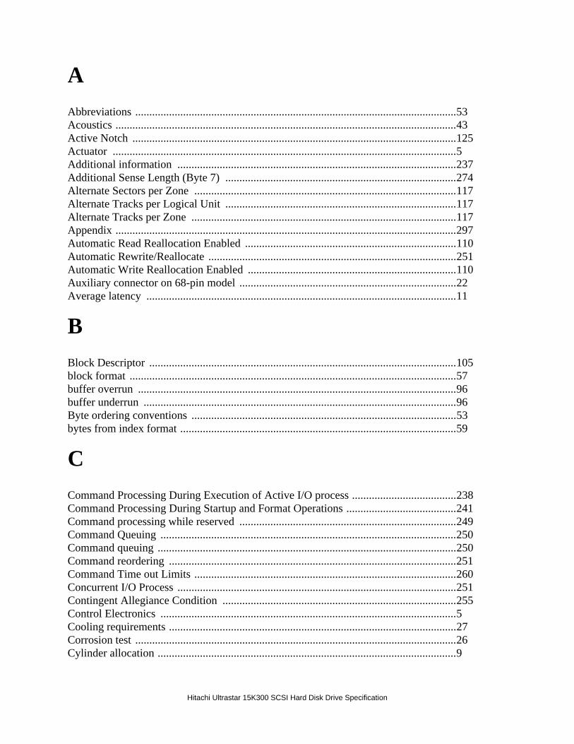
Hitachi Ultrastar 15K300 SCSI Hard Disk Drive Specification
AAbbreviations ..................................................................................................................53Acoustics .........................................................................................................................43Active Notch ...................................................................................................................125Actuator ..........................................................................................................................5Additional information ...................................................................................................237Additional Sense Length (Byte 7) ..................................................................................274Alternate Sectors per Zone .............................................................................................117Alternate Tracks per Logical Unit ..................................................................................117Alternate Tracks per Zone ..............................................................................................117Appendix .........................................................................................................................297Automatic Read Reallocation Enabled ...........................................................................110Automatic Rewrite/Reallocate ........................................................................................251Automatic Write Reallocation Enabled ..........................................................................110Auxiliary connector on 68-pin model .............................................................................22Average latency ..............................................................................................................11
BBlock Descriptor .............................................................................................................105block format ....................................................................................................................57buffer overrun .................................................................................................................96buffer underrun ...............................................................................................................96Byte ordering conventions ..............................................................................................53bytes from index format ..................................................................................................59
CCommand Processing During Execution of Active I/O process .....................................238Command Processing During Startup and Format Operations .......................................241Command processing while reserved .............................................................................249Command Queuing .........................................................................................................250Command queuing ..........................................................................................................250Command reordering ......................................................................................................251Command Time out Limits .............................................................................................260Concurrent I/O Process ...................................................................................................251Contingent Allegiance Condition ...................................................................................255Control Electronics .........................................................................................................5Cooling requirements ......................................................................................................27Corrosion test ..................................................................................................................26Cylinder allocation ..........................................................................................................9

HItachi Ultrastar 15K300 SCSI Hard Disk Drive Specification
DData Error Logging .........................................................................................................264Data Integrity ..................................................................................................................15data phase save data pointer (DPSDP) ...........................................................................108Data reliability ................................................................................................................33Data sheet ........................................................................................................................7Data transfer speed ..........................................................................................................12DC power requirements ..................................................................................................29Defect Descriptor ............................................................................................................57defect descriptor ..............................................................................................................57defect list .........................................................................................................................56Deferred Error Condition ................................................................................................241Degraded Mode ...............................................................................................................242, 266device cache fast writes ..................................................................................................97device cache partial read hits ..........................................................................................97device cache write hits ....................................................................................................97Diagnostics ......................................................................................................................256Disable Block Descriptor ................................................................................................102Download Microcode and Save (Mode 0101b) ..............................................................212Drive characteristics .......................................................................................................7Drive mounting ...............................................................................................................40Drive ready time .............................................................................................................12
EElectrical interface specification .....................................................................................19Electromagnetic Compatibility .......................................................................................47enclosure services ...........................................................................................................254Environment ....................................................................................................................25Equipment errors .............................................................................................................33Error Recovery Procedure ...............................................................................................15
FFailure prediction (PFA/S.M.A.R.T) ..............................................................................33Fixed-disk Subsystem Description .................................................................................5FORMAT UNIT .............................................................................................................54format unit .......................................................................................................................54Formatted capacity ..........................................................................................................7Full stroke seek time .......................................................................................................10

Hitachi Ultrastar 15K300 SCSI Hard Disk Drive Specification
GGeneral ............................................................................................................................1Glossary ..........................................................................................................................1Grown Defect List (Glist) ...............................................................................................160
HHead Disk Assembly ......................................................................................................5Heads unload and actuator lock ......................................................................................40
IIdentification ...................................................................................................................45Idle Time Function ..........................................................................................................260Incorrect Initiator Connection .........................................................................................238Incorrect Length Indicator (Bit 5 of byte 2) ....................................................................272Interface connector ..........................................................................................................37Internal Error Condition ..................................................................................................241Invalid LUN in Identify Message ...................................................................................237
LLabels ..............................................................................................................................45Log Page Parameters ......................................................................................................76LOG SELECT .................................................................................................................72LOG SELECT (4C) ........................................................................................................72LOG SENSE ...................................................................................................................75LOG SENSE (4D) ..........................................................................................................75Logical Block Cache Segment Size ................................................................................122
MMaximum Burst Size ......................................................................................................116Maximum Pre-fetch ........................................................................................................122Maximum Pre-fetch Ceiling ...........................................................................................122Mechanical dimensions ...................................................................................................35Mechanical positioning ...................................................................................................10Mechanical specifications ...............................................................................................35Merge G-List into P-List .................................................................................................107Minimum Pre-fetch .........................................................................................................122

HItachi Ultrastar 15K300 SCSI Hard Disk Drive Specification
MODE SELECT .............................................................................................................100, 101MODE SELECT (15) .....................................................................................................100MODE SELECT (55) .....................................................................................................101MODE SENSE (1A) .......................................................................................................102MODE SENSE (5A) .......................................................................................................137Mounting positions and tappings ....................................................................................38Multiple Initiator Environment .......................................................................................255multiple initiator systems ................................................................................................254
NNon-arbitrating systems ..................................................................................................254Non-operating shock .......................................................................................................42
OOperating conditions .......................................................................................................25Operating shock ..............................................................................................................41Operating vibration .........................................................................................................41Option jumper block .......................................................................................................22Outline ............................................................................................................................35Outline of the drive .........................................................................................................3overrun counter ...............................................................................................................96
PPackaging ........................................................................................................................26Page Code Valid .............................................................................................................169Page Format ....................................................................................................................187Parameter data for Read Keys .........................................................................................140Parameter data for Read Reservations ............................................................................141Parameter list ..................................................................................................................144Performance characteristics ............................................................................................9Persistent Reservation .....................................................................................................139PERSISTENT RESERVE IN (5E) .................................................................................139PERSISTENT RESERVE OUT .....................................................................................142, 146PERSISTENT RESERVE OUT (5F) .............................................................................142, 146Persistent Reserve Out Parameter list .............................................................................144Physical format ...............................................................................................................17physical sector format .....................................................................................................60Physical Sector Format (101b) .......................................................................................163Post Error ........................................................................................................................111Power connector .............................................................................................................19

Hitachi Ultrastar 15K300 SCSI Hard Disk Drive Specification
Power consumption efficiency index ..............................................................................32Power supply current, average, and peak ........................................................................30Predictive Failure Analysis .............................................................................................270PRE-FETCH ...................................................................................................................147Preventive maintenance ..................................................................................................33Primary Defect List .........................................................................................................160Priority Commands .........................................................................................................249Priority commands ..........................................................................................................249
RRandom vibration ...........................................................................................................41READ (10) - (28) ............................................................................................................149Read Ahead .....................................................................................................................254READ BUFFER (3C) .....................................................................................................153Read Buffer Full Ratio ....................................................................................................115Read Cache Disable ........................................................................................................122READ CAPACITY .........................................................................................................157READ CAPACITY command ........................................................................................157Read Continuous .............................................................................................................110READ DEFECT DATA (37) ..........................................................................................160READ DEFECT DATA (B7) .........................................................................................164READ LONG command .................................................................................................166Read Retry Count ............................................................................................................111REASSIGN BLOCKS (07) ............................................................................................167Reassigned format (Glist) ...............................................................................................17RECEIVE DIAGNOSTICS (1C) ....................................................................................169Recommended Initiator ERP ..........................................................................................262RELEASE (17) ...............................................................................................................172RELEASE (57) ...............................................................................................................173Reliability ........................................................................................................................33REPORT LUNS (A0) .....................................................................................................176Report Recovered Non Data Errors ................................................................................108REQUEST SENSE (03) ..................................................................................................182Reselection Timeout .......................................................................................................254RESERVE (16) ...............................................................................................................183RESERVE (56) ...............................................................................................................184Reserved Area .................................................................................................................170Reset ................................................................................................................................255Reset condition ...............................................................................................................255REZERO UNIT (01) .......................................................................................................185Ripple voltage .................................................................................................................32

HItachi Ultrastar 15K300 SCSI Hard Disk Drive Specification
SSafety ..............................................................................................................................49SCSI Command Set ........................................................................................................51SCSI Control Byte ..........................................................................................................53SCSI Message System ....................................................................................................219SCSI Protocol .................................................................................................................237SCSI Sense Data .............................................................................................................271SCSI Sense Data Format .................................................................................................271SCSI Status Byte .............................................................................................................217SCSI Status Byte Reporting ............................................................................................237Sectors per Track ............................................................................................................118SEEK (10) - (2B) ............................................................................................................186SEEK (6) - (0B) ..............................................................................................................186seek counter ....................................................................................................................95Seek errors ......................................................................................................................33seeks ................................................................................................................................96Segmented Caching ........................................................................................................254Selection without ATN ...................................................................................................255SEND DIAGNOSTIC (1D) ............................................................................................187sense data ........................................................................................................................254Sense Data Description ...................................................................................................272Sense Key (Bit 3 - 0 of byte 2) .......................................................................................273Service Action .................................................................................................................139, 143Shipped format (Plist) .....................................................................................................17Shipping conditions ........................................................................................................25Single Initiator Selection ................................................................................................254Size Enable .....................................................................................................................121Sound power levels .........................................................................................................43Spindle stop time ............................................................................................................12START STOP UNIT (1B) ..............................................................................................192Start/stop cycles ..............................................................................................................33Storage requirements ......................................................................................................26Storage time ....................................................................................................................26Summary .........................................................................................................................145Supported Messages .......................................................................................................220Supported messages ........................................................................................................220SYNCHRONIZE CACHE (35) ......................................................................................193
TTagged Queuing ..............................................................................................................250Temperature and humidity ..............................................................................................25Temperature Threshold ...................................................................................................108

Hitachi Ultrastar 15K300 SCSI Hard Disk Drive Specification
Temperature warning ......................................................................................................33TEST UNIT READY (00) ..............................................................................................195Throughput ......................................................................................................................13Track Skew Factor ..........................................................................................................118Tracks per Zone ..............................................................................................................118Transfer Block ................................................................................................................110Type ................................................................................................................................143
UUEC list ...........................................................................................................................297UL and CSA standard conformity ..................................................................................49underrun counter .............................................................................................................96Unit Attention Condition ................................................................................................268unit attention condition ...................................................................................................240Untagged Queuing ..........................................................................................................250
VVerify ..............................................................................................................................270VERIFY (2F) ..................................................................................................................196Vibration and shock ........................................................................................................41
WWRITE (10) - (2A) .........................................................................................................202WRITE (6) - (0A) ...........................................................................................................201WRITE AND VERIFY (2E) ...........................................................................................207, 209WRITE BUFFER (3B) ...................................................................................................213Write Buffer Empty Ratio ...............................................................................................115Write Cache ....................................................................................................................251Write Cache Enable ........................................................................................................121WRITE LONG (3F) ........................................................................................................214Write Retention Priority ..................................................................................................122Write Retry Count ...........................................................................................................111WRITE SAME (41) ........................................................................................................215
Zzero seeks ........................................................................................................................96

HItachi Ultrastar 15K300 SCSI Hard Disk Drive Specification
© Copyright Hitachi Global Storage Technologies
Hitachi Global Storage Technologies5600 Cottle RoadSan Jose, CA 95193Produced in the United States
04/07
All rights reserved Ultrastar™ is a trademark ofHitachi Global Storage Technologies.
Microsoft, Windows XP, and Windows are trademarks of Microsoft Corporation in the United States, other countries, or both.
Other product names are trademarks or registered trade-marks of their respective companies. References in this publication to Hitachi Global Storage Technologies products, programs or services do not imply that Hitachi Global Storage Technologies intends to make these available in all countries in which Hitachi Global Storage Technologies operates.
Product information is provided for information pur-poses only and does not constitute a warranty. Information is true as of the date of publication and is subject to change. Actual results may vary. This publication is for general guidance only. Photo-graphs may show design models.
09 April 2007