Embed Size (px)
DESCRIPTION
training notes
Citation preview

Handover in WCDMA

Page 2
Course Contents
Chapter 1 Overview
Chapter 2 Handover parameters
Chapter 3 Handover procedure

Page 3
Introduction
Handover is the most important part of mobility management .
The purpose of handover is that a UE in CELL_DCH state is
served continuously as it moves.
There are
• Intra-frequency handovers,
• Inter-frequency handovers,
• Inter-system , a.k.a. Inter-Radio Access Technology (RAT),
handovers.

Page 4
Intra-Frequency Handovers
Softer handover
Handover between two sectors of the same NodeB (handled by NodeB itself)
Maximum Ratio Combining (MRC) occurs in both the UL and DL
Soft handover (SHO)
Handover between two sectors of the different NodeBs (handled by RNC)
MS is simultaneously connected to multiple cells from different Node Bs
DL: MRC by UE & UL: Frame Selection Combining by RNC.
Hard handover
Occurs when
• inter-RNC SHO is not possible (Iur not supported or Iur congestion)
• Some high speed data service is required/requested, e.g. HSPA
Decision procedure is the same as SHO (i.e. RNC controlled)
Causes temporary disconnection of the user
Handover types

Page 5
Handover types
Inter-Frequency Handover
Can be intra-NodeB, intra-RNC, inter-RNC,
Decision algorithm is located in and performed by RNC.
Inter-RAT Handover
Handovers between GSM and WCDMA

Page 6
Comparison between Soft and Softer
Handovers
Page 7
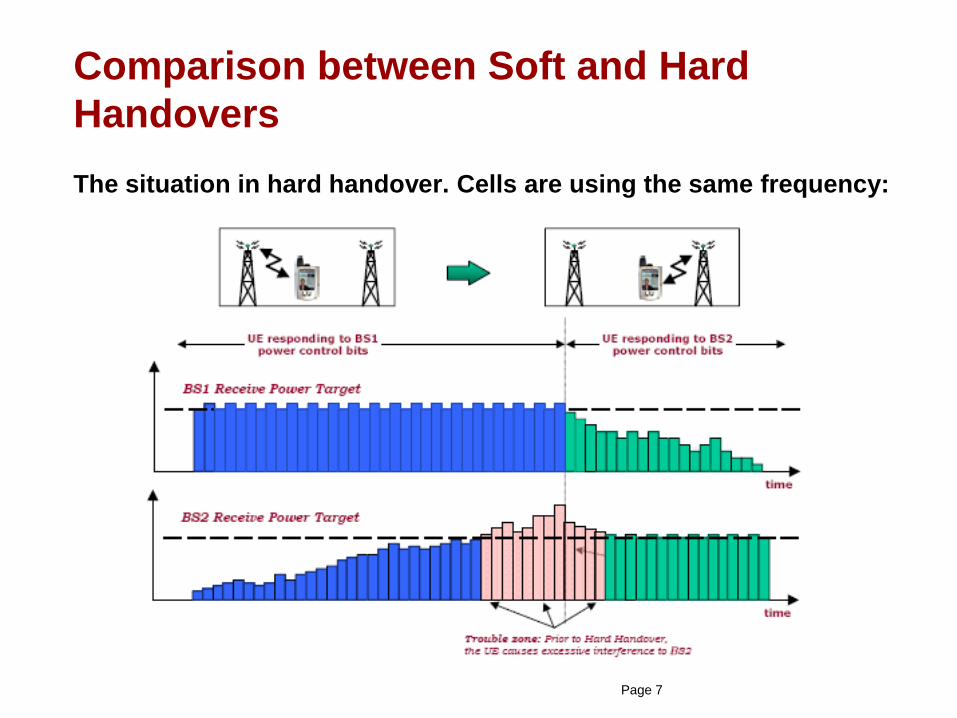
Comparison between Soft and Hard
Handovers
The situation in hard handover. Cells are using the same frequency:

Page 8
Comparison between Soft and Hard
Handovers (cont.)
The situation in soft handover. Cells are using the same frequency:

Page 9
Comparison between Soft and Hard
Handovers (cont.)
Item Soft Handover Hard Handover
The number of cells in
the active set
Several (normally
up to 3, but max.
could be 6)
Only one
Interruption during
handover
No Yes
The frequencies of
cells
Only happens in
Intra-frequency
cells
Can happen in Intra-
frequency cells or Inter-
frequency cells
Utilization of downlink
and transmission
resources
Occupies more
resources
Occupies less resources

Page 10
Comparison between Soft and Hard
Handovers (cont.)
Soft handover scenario Hard handover scenario

Page 11
Comparison between Soft and Hard
Handovers (cont.)
Controlling RNC (C-RNC): A role an RNC can take with respect to a specific
set of Node B's.
There is only one Controlling RNC for any Node B.
The Controlling RNC has the overall control of the logical resources of its
Node B's.

Page 12
Comparison between Soft and Hard
Handovers (cont.)
Serving RNC (S-RNC): A role an RNC can take with respect to a specific
connection between an UE and UTRAN.
There is one Serving RNC for each UE that has a connection to UTRAN.
The Serving RNC is in charge of the radio connection between a UE and the
UTRAN.
The Serving RNC terminates the Iu for this UE.

Page 13
Comparison between Soft and Hard
Handovers (cont.)
Drift RNC (D-RNC): A role an RNC can take with respect to a serving RNC.
It provides macro-diversity combining and splitting.
There could be more than one Drift RNC for a UE.
It performs transparent routing of data on Iub and Iur interfaces.

Maximum Ratio Combination
Page 14
• Each signal reception branch is multiplied by a weight factor that is
proportional to the signal amplitude.
• Branches with a stronger signal are further amplified, while weak
signals are attenuated.

Frame Selection Combination
Page 15
• Decodes the signal received by each cell individually and selects only
one of the correctly decoded blocks for further processing by higher
layers.
• Compared to Frame selection combination, Maximum ratio
combination provides both diversity and power gain.
• Maximum ratio combination has a gain of 2-3 dB relative to Frame
selection combination.

Frame Selection Combination (cont.)
Page 16

Page 17
Three Steps of Handover
Decision
Execute
Measurement
Measurement PhaseMeasurement control vs. Measurement report messagesMeasurement execution and the result processingMainly accomplished by UE
Decision PhaseBased on Measurement reports from UEConsiders distribution ofresourcesMainly accomplished by RRM in RNC
Execution PhaseBased on signalingShould support rollback in case of failureMeasurement control refresh

Measurement Control vs. Message Report
Page 18
Measurement Control: From network to UE
Measurement Report: From UE to network

Measurement Control vs. Message Report
(cont.)
Page 19
Intra-frequency soft(er) handover

Measurement Control vs. Message Report
(cont.)
Page 20
Hard handover (intra-frequency or inter-frequency)

Page 21
Course Contents
Chapter 1 Overview
Chapter 2 Handover parameters
Chapter 3 Handover procedure

Page 22
Chapter 2 Handover parameters
2.1 Intra-frequency handover
2.2 inter-frequency handover
2.3 inter-system handover

Page 23
Intra-frequency Measurement Events
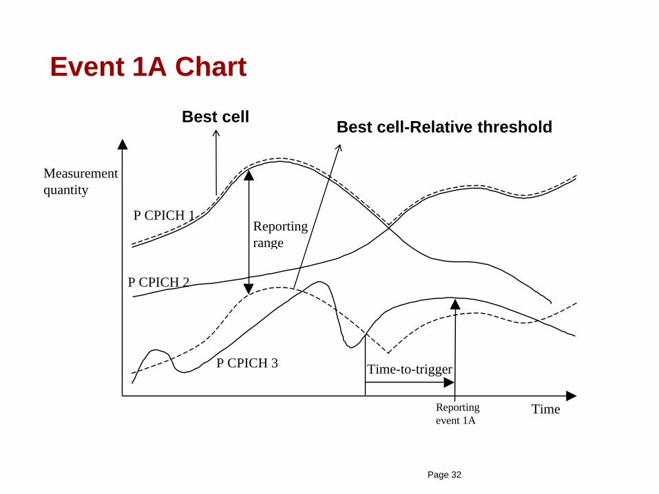
Event 1A,A primary pilot channel enters the reporting range. When
the active set of UE is full, UE stops reporting 1A event;
Event 1B,A primary pilot channel leaves the reporting range;
Event 1C,A primary pilot channel out of active set is better
than a primary pilot channel in the active set;
Event 1D,The best cell in the active set changes;
Event 1F , A primary pilot in the active set becomes worse than an
absolute threshold

Page 24
Measurement parameters
Report range or relative threshold: As higher it is, it is easier to
trigger a particular event or vice-versa.
Hysteresis: Related to slow-fading characteristics. The greater it
is, the less ping-pong effect and misjudgement can be caused.
However, this would bring a delay for triggering the event.
Time to Trigger: Also related to slow-fading characteristics. Has
similar characteristics as hysteresis.

Page 25
Measurement parameters (cont.)
Cell-individual Offsets: used as an offset to control promoting or
avoiding handover to a particular cell.
Layer3 filter coefficient: controls the impact of each cell in the
active set on the triggering decision.
The greater it is, the higher the soft handover relative threshold.
When equal to 0, only the best cell in the active set could impact
on the decision.

Page 26
Measurement parameters (cont.)
Condition for measurement reporting:
• Periodic Reporting,
• Event Reporting.
Metric to be measured:
• CPICH Ec/No,
• CPICH RSCP.

Page 27
Measurement parameters (cont.)
Measurement parameters and conditions are transferred within
Measurement Control messages:

Page 28
Measurement parameters (cont.)
Measurement parameters and conditions are transferred within
Measurement Control messages:

Page 29
Measurement parameters (cont.)
Measurement parameters and conditions are transferred within
Measurement Control messages:

Page 30
Triggering of Event 1A
Event 1A,A primary pilot channel enters the reporting range. When
the active set of UE is full, UE stops reporting 1A event.

Page 31
Triggering of Event 1A (cont.)
From UE point of view, WCDMA cells are divided into
• Active Set cells: Cells with which there is a radio link established
through soft(er) handover,
• Monitored Set cells: Neighbours of the cells in the active set. They
could be intra-frequency, inter-frequency and/or inter-system,
• Detected Set cells: Other cells than the above that are detected.
Unless implemented otherwise, total number of cells is limited to 32
for each set.
Page 32
Event 1A Chart
Reporting
event 1A
Measurement
quantity
Time
Time-to-trigger
P CPICH 1Reporting
range
P CPICH 2
P CPICH 3
Best cellBest cell-Relative threshold

Event 1A from TEMS
Page 33

Page 34
Triggering of Event 1B
Event 1B,A primary pilot channel leaves the reporting range.

Page 35
Event 1B Chart
Best cellBest cell-Relative threshold

Event 1B from TEMS
Page 36

Page 37
Impact of Parameters for Events 1A and 1B
Report Range or Relative threshold• Set values for Events 1A and 1B separately,
• 1A < 1B,which makes deleting RL is more difficult, and it can avoid
ping-pong handover,
• Usually 1A: 3dB; 1B: 6dB,
• Relative thresholds are set separately for CS and PS services!
Time to trigger• Value for each event can be set separately,
• Usually, 1B>1A,which makes deleting RL is more difficult, and it can
avoid ping-pong handover,
• Usually, 1A: 320ms, 1B: 640ms.
Layer 3 filter coefficient• Only one value for all intra-frequency measurements,
• Sensitive to the delay of event trigger and ping-pong handover,
• Usually:3

Page 38
Triggering of Event 1C
Event 1C,A primary pilot channel out of active set is better
than a primary pilot channel in the active set;
It can only be triggered if the active set is full. Otherwise, Event 1A
is triggered!

Page 39
Event 1C Chart
Reporting
event 1C
Reporting
event 1C
Measurement
quantity
Time
P CPICH 2
P CPICH 1
P CPICH 3
P CPICH 4

Event 1C from TEMS
Page 40

Page 41
Triggering of Event 1D
Event 1D,The best cell in the active set changes;

Page 42
Event 1D Chart
Reporting
event 1D
Measurement
quantity
Time
P CPICH 2
P CPICH 1
P CPICH3

Event 1D from TEMS
Page 43

Page 44
Triggering of Event 1F
Event 1F,A primary pilot in the active set becomes worse than an
absolute threshold;
If there is no more primary pilot left in the active set, RNC may
decide for a blind handover of UE to an inter-frequency cell, if
available.

Page 45
Chapter 2 Handover parameters
2.1 Intra-frequency handover
2.2 inter-frequency handover
2.3 inter-system handover

Page 46
Inter-frequency handover overviewInter-frequency handover can be triggered based on
• Coverage: for continuity of calls while avoiding drops.
• Load and/or service: for balancing the traffic between the
cells and moving certain users/applications to the other
carrier in case required, e.g. UMTS carrier vs. HSPA carrier.
• Speed: In what so called Hierarchical Cell Structure (HCS),
cells are divided into macro and micro cells. Those users
with higher speeds stay at macro cells whereas those with
lower speed are served by micro cells.

Page 47
Inter-frequency Measurement Events

Page 48
Triggering of Event 2D
Event 2D,When the current signal quality is lower than the preset
threshold, the system enables compressed mode and starts inter-
frequency measurement

Event 2D from TEMS
Page 49

Page 50
After Event 2D
After receiving event 2D, the RNC would perform either
• Periodical measurement reporting, or,
• Event 2B triggered measurement reporting,
depending on if inter-frequency measurement reporting mode is
chosen as periodical or event based.
Inter-frequency handover mode will continue till event 2F is received
or inter-frequency measurement timer expires!

Page 51
After Event 2D (cont.)
Periodical measurement reporting is more recommended than to
event triggered measurement reporting.
It leads to a higher handover success ratio since even if handover
fails, RNC tries handover to the same cell upon reception of a
periodical report from UE.
RNC makes the handover decision based on the periodic
measurement reports provided by UE.

Compressed Mode
Page 52
UE cannot operate on two different frequencies at the same time.
Compressed mode is required to be able to match with the
frequency of a cell that uses another frequency than the one
currently used by the serving cell.
There are two possible ways of moving to compressed mode:
• Spreading factor reduction, i.e. SF/2,
• Higher layer scheduling.

Periodical Measurement
Page 53
Inter-frequency handover based on periodical measurement
requires holding following conditions during hard handover trigger
delay time:
1.CPICH RSCP and Ec/No of the inter-frequency cell should be
higher than the corresponding minimum access thresholds,
2.

Periodical Measurement (cont.)
Page 54
Inter-frequency handover based on periodical measurement
is stopped if:
1.Either CPICH RSCP or Ec/No of the inter-frequency cell falls
below the corresponding minimum access threshold,
2.The following condition is no longer satisfied:

Page 55
Triggering of Event 2F
Event 2F,When the current signal quality is higher than the preset
threshold, the system disables compressed mode and stops inter-
frequency measurement

Event 2F from TEMS
Page 56

Page 57
Triggering of Event 2B
Event 2B,When the current signal quality is lower than the preset
threshold and the signal quality of an inter-frequency neighbouring
cell is also higher than the preset threshold, the system triggers an
inter-frequency handover based on coverage.

Page 58
Triggering of Event 2C
Event 2C,The estimated quality of an inter-frequency cell is higher
than the preset threshold.

Page 59
Chapter 2 Handover parameters
2.1 Intra-frequency handover
2.2 inter-frequency handover
2.3 inter-system handover

Page 60
Inter-system handover overviewApplication scenario: WCDMA <-> GSM
• Different radio access technology is used after handover,
• From WCDMA to GSM, UE switches to compressed mode to be
able to perform measurement process in GSM.
Advantages
• For coverage, it can solve the problems from one system to another
system,
• For capacity, it can enhance the utilizing efficiency of equipments in
terms of load (GSM->WCDMA).
Disadvantages
• The flow is complicated, and it demands higher compatibility for
equipments,
• Demands more complicated UE.

Page 61
Inter-system handover overview (cont.)
When UE is in CELL-DCH state, moving between these two
technologies is called as handover for CS services whereas as
cell reselection for PS services.
WCDMA to GSM Handover could be based on:
• Coverage: When CPICH RSCP or CPICH Ec/No of the serving
cell is lower than a threshold while RSSI of the GSM neighbour
cell is higher than the corresponding threshold,
• Load: The load of serving cell is higher than a threshold,
• Service: When requested service could be supplied by GSM
network.

Page 62
Inter-system handover overview (cont.)
If handover is based on coverage, then it is either periodical or
based on Event 3A reporting.
However, if handover is based on load or service, then it is based
on Event 3C reporting.
Confirmation of BSIC of the GSM cell is optional. However, it would
make handover more reliable.

Periodical Measurement
Page 63
Inter-system handover based on periodical measurement
requires holding of following condition during handover trigger
delay time:

Page 64
Event reporting
Event 2D: initiate GSM measurement.
Event 2F: stop GSM measurement.
Event 3A : The estimated quality of the used UTRAN frequency is lower
than a certain threshold, and that of the other system is higher than a
certain threshold.
Event 3C: The estimated quality value of the other system is higher
than an absolute threshold.
Inter-system handover decision

Page 65
Triggering of Event 2D
Event 2D,When the current signal quality is lower than the preset
threshold, the system enables compressed mode and starts
measuring inter-system cells:

Event 2D from TEMS
Page 66

Page 67
After Event 2D
After receiving event 2D, the RNC would perform either
• Periodical measurement reporting or
• Event 3A triggered measurement reporting
depending on if inter-system measurement reporting mode is
chosen as periodical or event based.
Inter-frequency handover mode will continue till event 2F is received
or inter-frequency measurement timer expires!

Page 68
Triggering of Event 3A
Event 3A :The estimated quality value of the used UTRAN
frequency is lower than a certain threshold, and that of the other
system is higher than a certain threshold.

Event 3A from TEMS
Page 69

Page 70
Triggering of Event 3C
Event 3C : The estimated quality value of the other system is higher
than a absolute threshold.

Page 71
Course Contents
Chapter 1 Overview
Chapter 2 Handover parameters
Chapter 3 Handover procedure

Page 72
Chapter 3 Handover procedure
3.1 Intra-frequency handover
3.2 inter-frequency handover
3.3 inter-system handover

Page 73
Signaling Flow for Soft Handover (add RL)

Page 74
Signaling Flow for Soft Handover (del RL)
Page 75
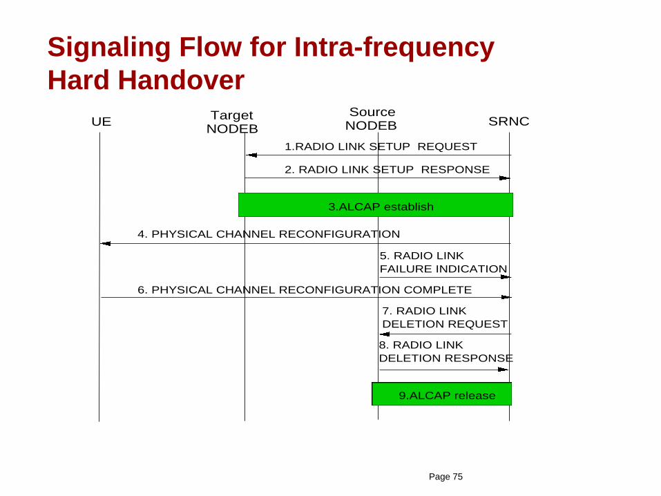
Signaling Flow for Intra-frequency
Hard Handover
UE
1.RADIO LINK SETUP REQUEST
Target NODEB
Source NODEB SRNC
2. RADIO LINK SETUP RESPONSE
3.ALCAP establish
4. PHYSICAL CHANNEL RECONFIGURATION
5. RADIO LINK
FAILURE INDICATION
6. PHYSICAL CHANNEL RECONFIGURATION COMPLETE
7. RADIO LINK
DELETION REQUEST
8. RADIO LINK
DELETION RESPONSE
9.ALCAP release

Page 76
Chapter 3 Handover procedure
3.1 Intra-frequency handover
3.2 inter-frequency handover
3.3 inter-system handover

Page 77
Signaling Flow for Inter-frequency
Hard Handover (same RNC)UE
1.RADIO LINK SETUP REQUEST
Target NODEB
Source NODEB SRNC
2. RADIO LINK SETUP RESPONSE
3.ALCAP established
4. PHYSICAL CHANNEL RECONFIGURATION
5. RADIO LINK
FAILURE INDICATION
6. PHYSICAL CHANNEL RECONFIGURATION COMPLETE
7. RADIO LINK
DELETION REQUEST
8. RADIO LINK
DELETION RESPONSE
9.ALCAP released

Page 78
Signaling Flow for Inter-frequency
Hard Handover (different RNC)

Page 79
Chapter 3 Handover procedure
3.1 Intra-frequency handover
3.2 inter-frequency handover
3.3 inter-system handover

Page 80
Signaling Flow for WCDMA to GSM
Handover in CS Domain
1. Relocation
Required 2. Prepare
Handover 3. Handover
Request
4. Handover
Request Ack
12. Iu Release
Command
13. Iu Release
Complete 14. Send End
Signal Response
5. Prepare
Handover
Response
6. Relocation
Command
7. DCCH : Handover
from UTRAN Command
8. Handover
Detect
9. Handover Complete
10. Handover
Complete 11. Send
End
Signal
Request
UE Node B SRNC CN MSC BSC

Page 81
Signaling Flow for WCDMA to GSM
Handover in PS Domain

GSM -> WCDMA Handover and Cell
Reselection
Page 82
In Motorola BSS, GSM -> WCDMA Inter-RAT Handover and Cell-Reselection
functionalities are controlled by the features:
• GSM BSS Inter-RAT Handover
• FR 22879 Enhanced 2G-3G Handovers and Cell Reselection

GSM -> WCDMA Handover and Cell
Reselection (cont.)
Page 83
GSM BSS Inter-RAT Handover feature enables a multi-RAT MS:
– to perform cell reselection from GSM to WCDMA while in idle mode,
– to perform handover from a WCDMA cell to a GSM cell while in
dedicated mode.

GSM -> WCDMA Handover and Cell
Reselection (cont.)
Page 84
FR 22879 Enhanced 2G-3G Handovers and Cell Reselection feature provides
a multi-RAT MS:
– to perform handovers while in dedicated mode from a GSM cell to a
WCDMA cell,
– idle mode cell reselection functionality by providing blind search
support.
For this purpose, WCDMA frequencies are broadcast in the System
Information messages.

GSM -> WCDMA Handover and Cell
Reselection (cont.)
Page 85
On the other hand, MSC may trigger service-based handovers to WCDMA in
case requested service is not available in GSM.
To enable Inter-RAT Handover and Cell-Reselection between
a GSM and WCDMA cell, they should be defined as neighbours.
Depending on if a WCDMA cell is defined as BCCH and/or SACCH
neighbor during neighbor addition with add_neighbour command,
umts_ba_type parameter gets a value.

GSM -> WCDMA Handover and Cell
Reselection (cont.)
Page 86
• inter_rat_enabled: It can have values from 0 to 7, where setting of 7
allows idle and bi-directional dedicated handovers and cell reselections. In
fact, setting 0 to 3 for this parameter require the first feature enabled,
whereas 4 to 7 require the second feature enabled.
• blind_search_preference: decides for if blind search is to be performed
in the idle mode or not. If it is set, it reduces SI messages in DL, but
increases the time to synchronize with WCDMA cells.
• qsearch_i: it controls the RXLEV of the serving cell in the idle mode, i.e.
BCCH level, below or above which measurements on WCDMA neighbour
cells are triggered.
BSS-CELL Parameters

GSM -> WCDMA Handover and Cell
Reselection (cont.)
Page 87
• qsearch_c: it determines the RXLEV of the serving cell in the dedicated
mode, i.e. SACCH level, below or above which measurements on WCDMA
neighbour cells are triggered.
• qsearch_c_initial: till a valid qsearch_c is available, MS will use
qsearch_c_initial value. When it is equal to 0, it means to use qsearch_c
equal to qsearch_i.
• fdd_rep_quant: it decides for if the signal level or quality of a WCDMA
neighbor would be considered for handover.
BSS-CELL Parameters (cont.)

GSM -> WCDMA Handover and Cell
Reselection (cont.)
Page 88
• fdd_qoffset: minimum threshold in idle mode for RSCP measurements.
• fdd_qmin: minimum threshold in idle mode for Ec/No measurements.
• umts_cpich_ec_no_min: minimum threshold in dedicated mode for
Ec/No measurements.
• umts_cpich_rscp_min: minimum threshold in dedicated mode for RSCP
measurements.
BSS-CELL Parameters (cont.)

GSM -> WCDMA Handover and Cell
Reselection (cont.)
Page 89
• umts_ncell_avg_period: it sets the period of SACCH multiframes for the
averaging of WCDMA neighbour cell measurements.
• umts_meas_margin: is defined per neighbour to promote or avoid
handovers and cell reselections to a particular cell.
• umts_band_preferred: decides for the selection of a neighbor based on
its radio access technology if both GSM and WCDMA qualify.
BSS-CELL Parameters (cont.)

GSM -> WCDMA Handover and Cell
Reselection (cont.)
Page 90
• Service Handover: Normally this parameter belongs to MSC. It controls
handovers mandated by the MSC based on service. For example, it is
possible to handover all CS calls from WCDMA to GSM upon call setup. It
can be overwritten by umts_band_preferred parameter.
• inter_cell_handover: Setting this parameter as 3 avoids sending
handover required message from a BSC. It is very useful for test purposes.
• 3G_search_prio: It enables/disables BSIC decoding. Moreover, it works
with Service Handover. For restrictions on access to WCDMA, it is
disabled, set to 0.
BSS-CELL Parameters (cont.)

GSM -> WCDMA Handover and Cell
Reselection (cont.)
Page 91
• umts_ba_type: It takes a value following the parameter combination for
add_neighbour command in terms of UTRAN_BCCH and UTRAN_SACCH
neighbourhood. It is not possible to set this parameter manually. It is rather
the consequence of add_neighbour command.
• service_band_reporting: specifies the number of cells to be reported
from the GSM frequency band.
• fdd_multirat_reporting: determines the number of cells to be reported
from the WCDMA frequency band in the measurement report.
BSS-CELL Parameters (cont.)

GSM -> WCDMA Handover and Cell
Reselection (cont.)
Page 92
When a multi-RAT MS is in idle mode, these parameters are broadcast from
BSS via System Information Type 2quater.
System Information Type 2quater message includes
• 3G neighbor cells,
• qsearch_i,
• qsearch_c_initial,
• fdd_qoffset,
• fdd_rep_quant,
• fdd_multirat_reporting,
• fdd_qmin.

GSM -> WCDMA Handover and Cell
Reselection (cont.)
Page 93

GSM -> WCDMA Handover and Cell
Reselection (cont.)
Page 94
The concept of blind search in the idle mode enables BSS to broadcast
only WCDMA ARFCN information within the System Information Type
2quater message.
Although it reduces the amount of information within the System
Information Type 2quater message, it would increase the delay for MS to
perform cell reselection in the idle mode.

GSM -> WCDMA Handover and Cell
Reselection (cont.)
Page 95
In order for a reselection to a WCDMA cell,
• CPICH RSCP of this cell should be greater than the sum of receive level of
serving GSM cell and all of the six strongest GSM neighbor cells by a
margin of fdd_qoffset for 5 seconds.
• Ec/No value of WCDMA cell should be greater than or equal to the value
of fdd_qmin.
This phenomenon also applies for cell-reselections in packet-dedicated
mode.

GSM -> WCDMA Handover and Cell
Reselection (cont.)
Page 96
While moving to circuit-dedicated mode, MS communicates its Inter-
RAT capabilities to BSS within Classmark Change and UMTS Classmark
Change messages.

GSM -> WCDMA Handover and Cell
Reselection (cont.)
Page 97
Upon reception of Classmark Change and UMTS Classmark
Change messages, BSS starts sending Measurement Information
messages to the MS.
These messages include
• 3G neighbor cell description,
• qsearch_c,
• 3g_search_prio,
• fdd_rep_quant ,
• fdd_multirat_reporting,
values.

GSM -> WCDMA Handover and Cell
Reselection (cont.)
Page 98
GSM -> WCDMA Handover and Cell
Reselection (cont.)
Page 99
Upon reception of Measurement Information messages, measurements from
UTRAN neighbours are included in the list of MS measurements from 6 best
cells within Measurement Report and sent on the SACCH.
Based on the value of fdd_rep_quant parameter, MS reports
• RSCP, or
• Ec/No.

GSM -> WCDMA Handover and Cell
Reselection (cont.)
Page 100

GSM -> WCDMA Handover and Cell
Reselection (cont.)
Page 101
MS reported levels received within Measurement Report are averaged for
umts_ncell_avg_period.
If averaged value is higher than the minimum threshold
• utran_cpich_rscp_min, when fdd_rep_quant=0
• utran_cpich_ec_no_min, when fdd_rep_quant_min=1
plus the margin (utran_meas_margin), then reported 3G neighbor is qualified
for the handover and Handover Required message is sent from BSS to
MSC.

GSM -> WCDMA Handover and Cell
Reselection (cont.)
Page 102
Statistics and counters