Embed Size (px)
Citation preview
H A N D H E L D P R O D U C T S
Dolphin 7200 Handheld Computer and HomeBase™ User’s Guide
7200/UG Rev. E

Copyright
Copyright © October 2002 Hand Held Products. All rights reserved.
Portions of the software described in this document copyright © Microsoft Corporation. All Rights Reserved.
Information in this document is subject to change without notice. The software described in this document is furnished under a license agreement. The software may be used or copied only in accordance with the terms of this agreement. No part of this publication may be reproduced, stored in a retrieval system, or transmitted in any form or any means electronic or mechanical, including photocopying and recording for any purpose other than the purchaser's personal use without written permission of Hand Held Products.
Trademarks
Microsoft, Windows 3.11, Windows 95, Windows 2000, and Windows NT and Excel are trademarks or registered trademarks of Microsoft Corporation. RF Simplicity, Dolphin, Dolphin RF and HomeBase are trademarks or registered trademarks of Hand Held Products. iButton is a trademark of Dallas Semiconductor. Other product names mentioned in this document may be trademarks or registered trademarks of their respective companies and are hereby acknowledged.
Printed in U.S.A
Contacting Hand Held Products
Offices Serving North America
Skaneateles Falls, NY Tel: (800) 782-4263 Fax: (315) 685-3172 Charlotte, NC Tel: (800) 782-4263 Fax: (704) 998-3997
Offices Serving Europe, Middle East, and Africa
Europe Tel: Int+31 (0) 40 29 01 600 Fax: Int+31 (0) 40 24 25 672 United Kingdom Tel: Int +44 (0) 1 925 240055 Fax: Int +44 (0) 1 925 631280 France Tel: Int +33(0) 1 461 04111 Fax: Int +33(0) 1 461 04120 Germany Tel: Int +49 (0) 7 447 151377 Fax: Int +49 (0) 7 447 151378
Offices Serving Asia and the Pacific Rim
Hong Kong Tel: Int +852 2511 3050/2511 3132 Fax: Int +852 2511 3557 Japan Tel: Int +813 52127392 Fax: Int +813 32617372
Offices Serving Latin America
Naples, Florida Tel: (239) 263-7600 Fax: (239) 263-9689

Table of ContentsBefore You Begin................................................................................ 7
Welcome................................................................................................................7 Safety.....................................................................................................................8
Required Safety Labels .............................................................................................................. 8 RF Energy ................................................................................................................................ 10 Statement of Agency Compliance ............................................................................................ 10 FCC Class A Compliance Statement ........................................................................................ 10 Canadian Notice ....................................................................................................................... 11 CDRH Laser Safety Statement: 7200 Batch and RF Laser Models.......................................... 11 EN 60825-1 Laser Safety Statement ........................................................................................ 11 R&TTE Directive: 7200 802.11 Model ................................................................................... 11 Interference .............................................................................................................................. 13 Batteries ................................................................................................................................... 14 Care and Cleaning of the Dolphin ............................................................................................ 14
Chapter 1 Getting Started .............................................................. 15
About the Dolphin 7200 Handheld Computer ....................................................16 Accessories for the Dolphin ..................................................................................................... 16 Dolphin 7200 Models and Options .......................................................................................... 17 Bar Code Symbologies Supported............................................................................................ 18
Using Dolphin for the First Time........................................................................19 1 Checking Your Package ....................................................................................................... 19 2 Charging the Battery ............................................................................................................ 21 3 Turning the Dolphin On And Off ......................................................................................... 23 4 Setting the Date and Time .................................................................................................... 23
Chapter 2 Dolphin Basics ............................................................... 25
System Features...................................................................................................26 CPU.......................................................................................................................................... 26 Disk Drives............................................................................................................................... 26
Front Panel Physical Features .............................................................................26 Light Emitting Diodes (LED)................................................................................................... 26 Liquid Crystal Display (LCD).................................................................................................. 27 Speaker..................................................................................................................................... 27 RF Antenna .............................................................................................................................. 27
Using the Alphanumeric Keypad ........................................................................28 Key Combinations For Keypad Functions and Special Characters .......................................... 29
Using the Numeric Keypad .................................................................................30 Key Combinations For Keypad Functions and Special Characters .......................................... 31 Entering Alpha and Special Characters .................................................................................... 31
Display Symbols..................................................................................................32 Battery Charge.......................................................................................................................... 32 Keyboard Mode........................................................................................................................ 32
Back Panel Features ............................................................................................34 Laser Engine............................................................................................................................. 35 Image Engine............................................................................................................................ 35 Lanyard Eyelet for Optional Wrist Strap.................................................................................. 35
Battery Well ............................................................................................................................. 35 Reset Switch............................................................................................................................. 35
Maintaining the Dolphin’s Batteries ...................................................................36 Internal NiMH Backup Battery ................................................................................................ 36 NiMH Battery Pack................................................................................................................. 37 Storing Batteries....................................................................................................................... 38
Chapter 3 Dolphin® 7200 RF Handheld Computer................... 39
About the Dolphin 7200 RF Handheld Computer ..............................................40 802.11b-Compliant Dolphin 7200 RF Terminal ...................................................................... 40 Configuring Your 802.11b- Compliant Dolphin 7200 RF Terminal ........................................ 41 WLIF™-Compliant Dolphin 7200 RF Terminal...................................................................... 53 Dolphin 7200 RF Peripherals ................................................................................................... 56 Host Connectivity..................................................................................................................... 56 Terminal Emulation Keyboard Overlays.................................................................................. 59
Chapter 4 Dolphin® 7200 with iButton Reader Handheld Computer........................................................................................... 61
About Dolphin with iButton Reader Handheld Computer..................................62 What is an iButton? .............................................................................................62 Working with iButtons ........................................................................................63
IButtons supported by Dolphin with iButton Reader ............................................................... 63 Developing Applications with Dolphin with iButton Reader ................................................... 64
Chapter 5 Dolphin® 7200 RS-232 Handheld Computer..... 65
About Dolphin 7200 RS-232 Hand Held Computer ...........................................66 Charging The Battery Through The RS-232 Port ...............................................68 Sending and Receiving Data ...............................................................................68
Chapter 6 Dolphin® 7200 2D Terminal........................................ 69
About the Dolphin 7200 2D Hand Held Computer.............................................70 Supported Symbologies............................................................................................................ 70
Capturing Images ................................................................................................72 Lighting Conditions.................................................................................................................. 72
Dolphin 7200 2D Demo Software.......................................................................73 Installing the Dolphin 7200 Demo Applications.................................................73
Chapter 7 Using the Dolphin® 7200 HomeBase .......................... 80
Hub of the System ...............................................................................................81 Dolphin 7200 HomeBase Parts and Functions....................................................82
Charging Batteries In The Dolphin 7200 HomeBase ............................................................... 85 Setting Up For Communications.........................................................................87 Setting up the Dolphin HomeBase ......................................................................87
Configuring a Single Dolphin 7200 HomeBase ....................................................................... 90 Creating a Dolphin 7200 HomeBase Network ......................................................................... 91
Communicating with the Dolphin Terminal .......................................................95
Chapter 8 Using the Dolphin® 7200 Compact HomeBase.......... 96
Hub of the System ...............................................................................................97 Dolphin 7200 Compact HomeBase Parts and Functions ....................................98
Powering the Dolphin Terminal ............................................................................................. 100 Mounting the Dolphin 7200 Compact HomeBase.................................................................. 102
Setting Up For Communications.......................................................................104 Setting up the Dolphin Compact HomeBase.....................................................104 Communicating with the Dolphin Terminal .....................................................106
Chapter 9 Learning About the Dolphin OS and Development System Software ............................................................................. 107
Dolphin OS and Development System..............................................................108 Installation.............................................................................................................................. 108 Help File, Document and Utility Icons................................................................................... 110
Dolphin HHP Demo Program ...........................................................................111 Scanning A Barcode............................................................................................................... 117
Dolphin Utilities................................................................................................118 Dolphin Application Development ...................................................................123
Compiling Applications for the Dolphin ................................................................................ 123 Sample Applications............................................................................................................... 124 Building the Samples.............................................................................................................. 124 Compiling the Sample Programs............................................................................................ 125
Transferring Files to or from Dolphin...............................................................126 Using the YX.EXE Utility...................................................................................................... 126 Using the Dolphin File Transfer Program .............................................................................. 126
Dolphin EVS Engine.........................................................................................129 Dolphin ROM Image and Boot Loader .............................................................130
Upgrading the Dolphin ROM Image ...................................................................................... 130 Upgrading the Dolphin Boot Loader...................................................................................... 131
Chapter 10 Troubleshooting and Warranty Information Dolphin® 7200 Terminal ............................................................... 132
Just In Case........................................................................................................133 Before Calling For Application Support ...........................................................133 Troubleshooting the Dolphin Terminal and HomeBase....................................133 Warranty Information........................................................................................140
Who Is Covered By The Warranty......................................................................................... 140 Limited Warranty ................................................................................................................... 140 How Problems Should Be Handled........................................................................................ 142 Return Information ................................................................................................................. 142 How To Extend Your Warranty ............................................................................................. 144
Application Support ..........................................................................................144 Appendix A Dolphin 7200 Terminal Specifications.......................................145 Appendix B Bar Code Samples.......................................................................158 Appendix C Dolphin 7200 2D Decoding Demo Menu Layout.......................159

Appendix D Dolphin 7200 Scan Maps ...........................................................164 Appendix E IQ Imaging Test Target ...............................................................166 Appendix F GS-DOS Commands ...................................................................167 Appendix G Declarations of Conformity .......................................................176
7
Before You Begin
Welcome ongratulations on the purchase of your new Dolphin 7200 handheld computer. You have made a wise choice in selecting the Dolphin 7200, a device known worldwide for its ergonomic shape, light weight, versatility and single-handed data collection features.
The patented shape allows true, one-handed operation and fits either hand comfortably. Built to last, the Dolphin’s ruggedly built case houses a 386 microprocessor and DOS operating system that is easily programmable with standard programming tools like Microsoft Visual C/C++, Borland C/C++, Visual Basic or RF Simplicity.
Dolphin is one of the most durable devices available, and is designed to withstand repeated five-foot drops onto a concrete floor. It also resists extreme temperatures, humidity levels and dust conditions.
The Dolphin’s basic features include long-lasting Nickel Metal Hydride (NiMH) batteries, a large, easy-to-read 8 line x 20 character backlit display that can display text or graphics, a natural scan and viewing angle, and two keypad options. The multiple configurations available for the Dolphin 7200 make it one of the most versatile terminals in the automatic data collection industry. The terminal may be equipped with a scan engine capable of reading all standard bar code symbologies. Dolphin 7200 is also available with the IMAGETEAM ™ 4250 Image Engine, a low power, high-resolution digital image engine for omni-directional and auto-discrimination reading and decoding of linear barcodes, stacked linear (PDF417) and 2D matrix codes. The image engine functions like a digital camera and also provides OCR (Optical Character Recognition) functionality. Dolphin hand held computer also is available with an iButton reader. The Dolphin 7200 RS-232 terminal features a micro-DB9 RS-232 for serial data input/output and charging in addition to the infrared port. The Dolphin Wand product package is a non-scan Dolphin 7200 RS-232 and a SCANTEAM 6180 bar code wand reader/decoder. The Dolphin 7200 RF terminal may be equipped with an 802.11b or WLIF 2.4 GHz radio for real-time data collection applications.
Load up the Dolphin with your custom software application and the ultimate data collection solution for your business fits in the palm of your hand.
C

8
Safety The Dolphin 7200 handheld computer/bar code scanner meets or exceeds the requirements of all applicable standards organizations for safe operation. However, as with any electrical equipment, the best way to ensure safe operation is to know the possible risks.
The following safety guidelines are designed to protect both you and others around you. Please read them carefully before using your Dolphin.
Required Safety Labels
Dolphin 7200 hand held computers use a low power Visible Laser to scan bar codes. Short-term exposure to CDRH Class II laser light is not known to be harmful. As with any bright light source, such as the sun, you should avoid direct eye exposure. The following are required safety labels, as they should appear on the back panel of the Dolphin:
Figure 1 Required Safety Labels for Dolphin 7200 laser-equipped batch terminals
9
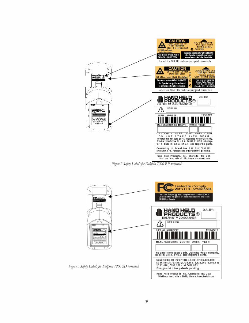
Figure 2 Safety Labels for Dolphin 7200 RF terminals
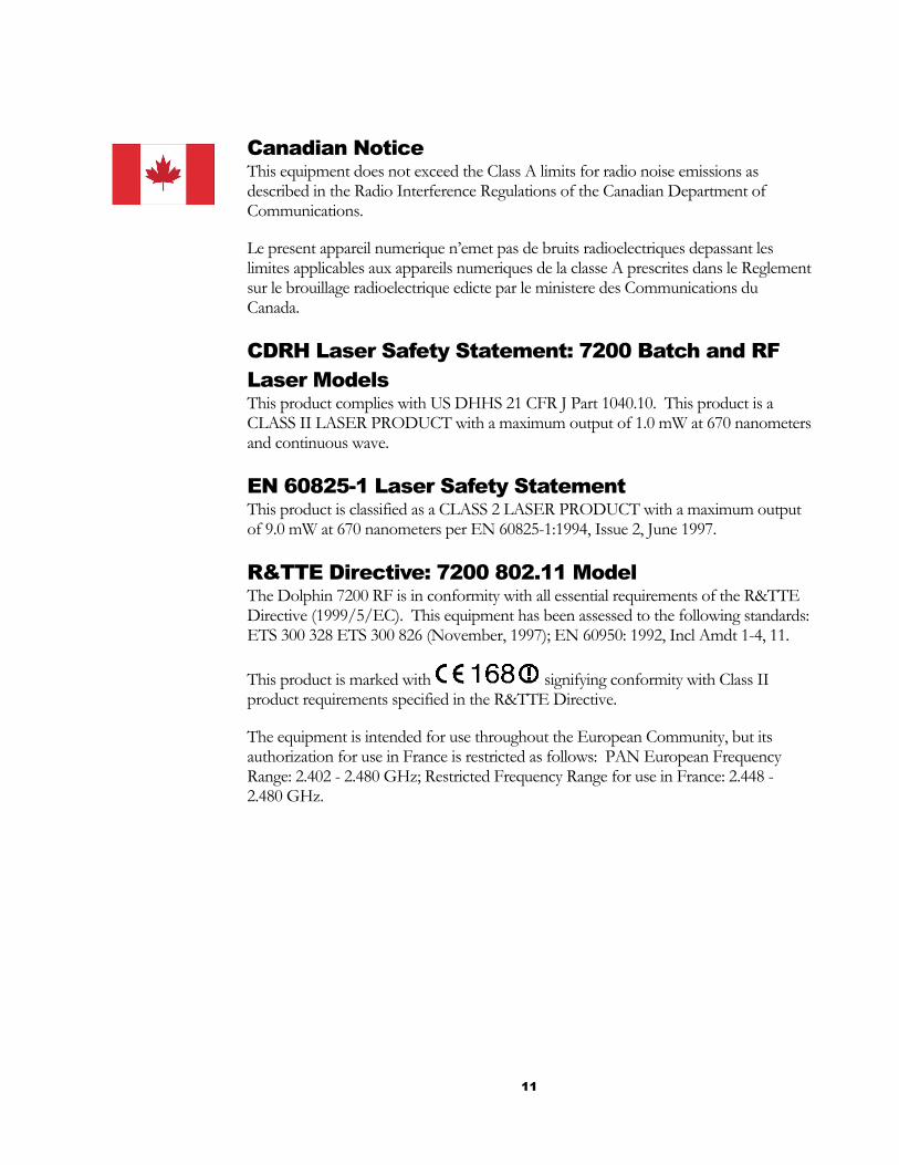
Figure 3 Safety Labels for Dolphin 7200 2D terminals
Label for 802.11b radio-equipped terminals
Label for WLIF radio-equipped terminals

10
RF Energy The Dolphin 7200 RF™ terminal is designed to comply with the most current applicable standards on safe levels of RF energy developed by the Institute of Electrical and Electronics Engineers (IEEE) and the American National Standards Institute (ANSI) and has been recommended for adoption by the Federal Communications Commission (FCC). In addition, the Dolphin RF complies with the specifications for an intentional radiator in Subpart C of Part 15 of the FCC’s code of federal regulations. The Dolphin RF also complies with the European specifications ETS 300328 (Type Test of Radio LAN to European standards) and ETS 300826 (EMC Testing of radio equipment).
Statement of Agency Compliance The Dolphin Batch and Dolphin RF terminals both comply with part 15 of the FCC Rules. Operation is subject to the following two conditions:
1. Devices may not cause harmful interference.
2. Devices must accept any interference received, including interference that may cause undesired operation.
FCC Class A Compliance Statement This equipment has been tested and found to comply with the limits for a Class A digital device pursuant to part 15 of the FCC Rules. These limits are designed to provide reasonable protection against harmful interference in a residential installation. This equipment generates, uses, and can radiate radio frequency energy and, if not installed and used in accordance with the instructions, may cause harmful interference to radio communications. However, there is no guarantee that interference will not occur in a particular installation. If this equipment does cause harmful interference to radio or television reception, which can be determined by turning the equipment off and on, the user is encouraged to try to correct the interference by one or more of the following measures:
• Reorient or relocate the receiving antenna. • Increase the separation between the equipment and receiver. • Connect the equipment into an outlet on a circuit different from that to which
the receiver is connected. • Consult the dealer or an experienced radio or television technician for help.
Caution: Any changes or modifications made to this device that are not expressly approved by Hand Held Products may void the user’s authority to operate the equipment.
11
Canadian Notice This equipment does not exceed the Class A limits for radio noise emissions as described in the Radio Interference Regulations of the Canadian Department of Communications.
Le present appareil numerique n’emet pas de bruits radioelectriques depassant les limites applicables aux appareils numeriques de la classe A prescrites dans le Reglement sur le brouillage radioelectrique edicte par le ministere des Communications du Canada.
CDRH Laser Safety Statement: 7200 Batch and RF Laser Models This product complies with US DHHS 21 CFR J Part 1040.10. This product is a CLASS II LASER PRODUCT with a maximum output of 1.0 mW at 670 nanometers and continuous wave.
EN 60825-1 Laser Safety Statement This product is classified as a CLASS 2 LASER PRODUCT with a maximum output of 9.0 mW at 670 nanometers per EN 60825-1:1994, Issue 2, June 1997.
R&TTE Directive: 7200 802.11 Model The Dolphin 7200 RF is in conformity with all essential requirements of the R&TTE Directive (1999/5/EC). This equipment has been assessed to the following standards: ETS 300 328 ETS 300 826 (November, 1997); EN 60950: 1992, Incl Amdt 1-4, 11.
This product is marked with signifying conformity with Class II product requirements specified in the R&TTE Directive.
The equipment is intended for use throughout the European Community, but its authorization for use in France is restricted as follows: PAN European Frequency Range: 2.402 - 2.480 GHz; Restricted Frequency Range for use in France: 2.448 - 2.480 GHz.
12
R&TTE Directive: 7200 Proxim Model
The Dolphin 7200 RF is in conformity with all essential requirements of the R&TTE Directive (1999/5/EC). This equipment has been assessed to the following standards: ETS 300 328 ETS 300 826 (November, 1997); EN 60950: 1992, Incl Amdt 1-4, 11.
This product is marked with signifying conformity with Class II product requirements specified in the R&TTE Directive.
The equipment is intended for use throughout the European Community, but its authorization for use in France is restricted as follows: PAN European Frequency Range: 2.402 - 2.480 GHz; Restricted Frequency Range for use in France: 2.448 - 2.480 GHz.

13
Regulatory and Safety Agency Approvals
Parameter Specification
U.S.A. Canada Europe Others
FCC Part 15, Class A IEC 0003 EN 55022 (CISPR22) Class A ETS 300 826 Type Certified EMC 89/336/EEC EN 50082-1:1997, EN55024
RF Approvals U.S.A. Canada Europe
FCC Part 15.247 Certified RSS 210 Certified ETS 300 328 Certified
The CE mark on the product indicates that the system has been tested to and conforms with the provisions noted within the 89/336/EEC Electromagnetic Compatibility Directive and the 73/23/EEC Low Voltage Directive.
For further information please contact, Hand Held Products (UK) Ltd. 1st Floor Dallam Court Dallam Lane Warrington, Cheshire WA2 7LT England Hand Held Products shall not be liable for use of our product with equipment (i.e., power supplies, personal computers, etc.) that is not CE marked and does not comply with the Low Voltage Directive.
Interference
Pacemakers, Hearing Aids and Other Electrically Powered Devices Most manufacturers of medical devices adhere to the IEC 601-1-2 standard. This standard requires devices to operate properly in an EM Field with a strength of 3V/m over a frequency range of 26 to 1000MHz.
The maximum allowable field strength emitted by the Dolphin is 0.3V/m according to Subpart B of Part 1 of the FCC rules. Therefore, the Dolphin RF will have no effect on medical devices that meet the IEC specification.

14
Microwaves The radio in the Dolphin RF terminal operates on the same frequency band as a microwave oven. Therefore, if you use a microwave within range of the Dolphin RF terminal you may notice performance degradation in your wireless network. However, both your microwave and your wireless network will continue to function.
The Dolphin Batch terminal does not contain a radio, and therefore, is not affected by microwave ovens.
Batteries • Use only the battery supplied with your Dolphin or a replacement battery
supplied, recommended, or approved by HHP.
• Replace a defective battery immediately as it could damage the Dolphin terminal.
• Never throw a used battery in the trash. It contains heavy metals and should be recycled according to local guidelines.
• Don’t short-circuit a battery or throw it into a fire. It can explode and cause severe personal injury.
• Excessive discharge damages a battery. Recharge the battery when your Dolphin indicates low battery power.
• Although your battery can be recharged many times, it will eventually be depleted. Replace it after the recommended usage period (about 500 charge cycles for the 1500 mAh NiMH battery) or if the battery does not hold a charge.
• If you are not sure the battery or charger is working properly, please send it to HHP or an authorized HHP service center, for inspection.
The Dolphin handheld computer/bar code scanner meets or exceeds all applicable standards and has been manufactured to the highest level of quality.
Care and Cleaning of the Dolphin When needed, clean the laser engine window and the LCD display with a clean non-abrasive, lint-free cloth.

15
Chapter 1 Getting Started Summarizes the Dolphin’s features, functions and accessories and getting it started for the first time.
C H A P T E R 1 G E T T I N G S T A R T E D
16
About the Dolphin 7200 Handheld Computer The Dolphin is a handheld computer and imager/bar code scanner designed for easy, single-handed data collection. It has a 386 33 MHz microprocessor that runs with GS-DOS and is PC-compatible.
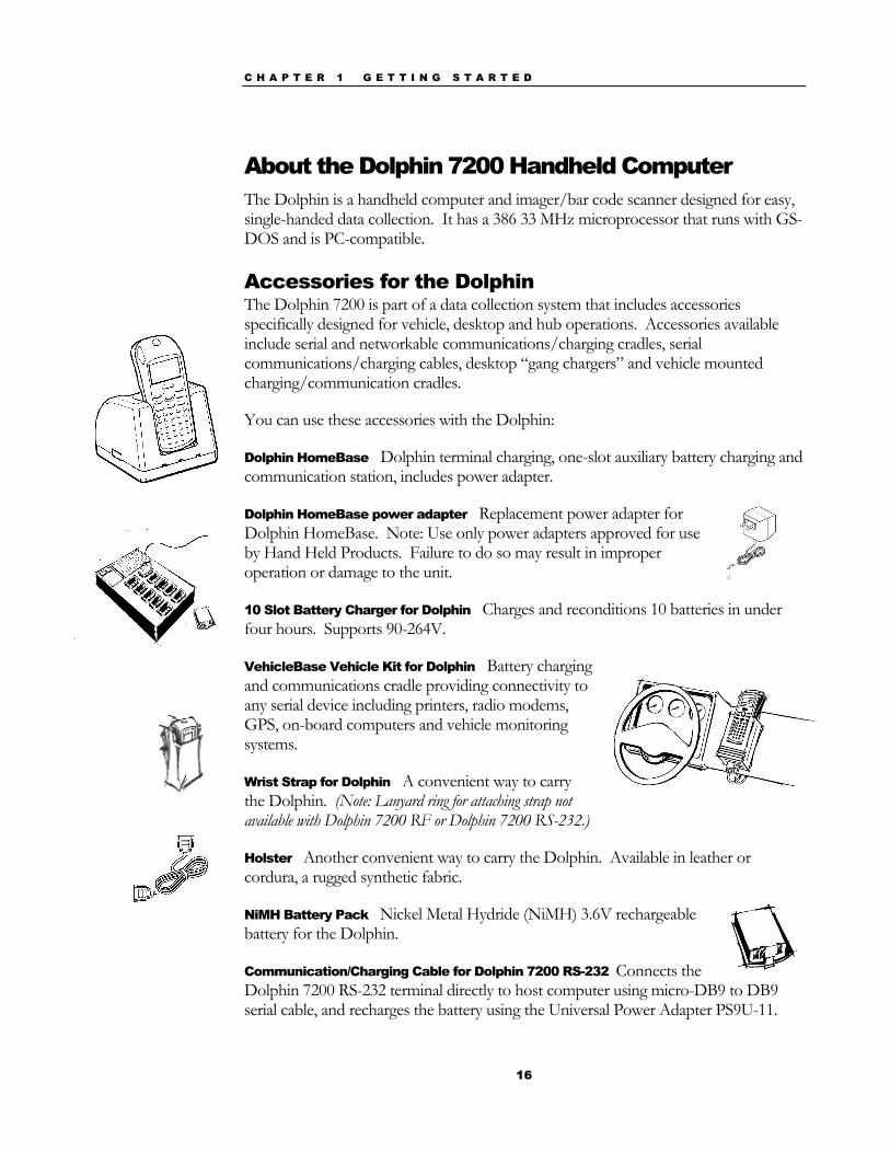
Accessories for the Dolphin The Dolphin 7200 is part of a data collection system that includes accessories specifically designed for vehicle, desktop and hub operations. Accessories available include serial and networkable communications/charging cradles, serial communications/charging cables, desktop “gang chargers” and vehicle mounted charging/communication cradles.
You can use these accessories with the Dolphin:
Dolphin HomeBase Dolphin terminal charging, one-slot auxiliary battery charging and communication station, includes power adapter.
Dolphin HomeBase power adapter Replacement power adapter for Dolphin HomeBase. Note: Use only power adapters approved for use by Hand Held Products. Failure to do so may result in improper operation or damage to the unit.
10 Slot Battery Charger for Dolphin Charges and reconditions 10 batteries in under four hours. Supports 90-264V.
VehicleBase Vehicle Kit for Dolphin Battery charging and communications cradle providing connectivity to any serial device including printers, radio modems, GPS, on-board computers and vehicle monitoring systems.
Wrist Strap for Dolphin A convenient way to carry the Dolphin. (Note: Lanyard ring for attaching strap not available with Dolphin 7200 RF or Dolphin 7200 RS-232.)
Holster Another convenient way to carry the Dolphin. Available in leather or cordura, a rugged synthetic fabric.
NiMH Battery Pack Nickel Metal Hydride (NiMH) 3.6V rechargeable battery for the Dolphin.
Communication/Charging Cable for Dolphin 7200 RS-232 Connects the Dolphin 7200 RS-232 terminal directly to host computer using micro-DB9 to DB9 serial cable, and recharges the battery using the Universal Power Adapter PS9U-11.

C H A P T E R 1 G E T T I N G S T A R T E D
17
SCANTEAM 6180 Bar Code Wand Reader/Decoder connects to the Dolphin 7200 through the terminal’s Micro-DB9 RS-232 port. For use only with non-scan Dolphin 7200 RS-232 terminal as part of Dolphin 7200 Wand product package.
6’ RS-232 Serial Cable Connects HomeBase to your desktop PC.
Contact your Value-Added Reseller for more information. For details about how to install or use any of these accessories, refer to the documentation provided with the product.
Dolphin 7200 Models and Options Hand Held Product’s family of Dolphin 7200 handheld portable data collection terminals includes these models:
The Dolphin® 7200 Batch terminal is a DOS programmable handheld computer/bar code scanner with a unique, ergonomic shape designed for single-handed use. The basic terminal has 2MB RAM and 8MB FLASH EEPROM memory. It also features an IrDA infrared transceiver for data communications.
The Dolphin® 7200 with iButton Reader handheld computer integrates the basic functionality of the Dolphin Batch terminal with iButton™ technology that allows the terminal to read and write data from and to iButtons. The iButton reader is a function and feature extension of the Batch terminal.
The Dolphin® 7200 RF terminal integrates the basic functionality of the Batch terminal with a 2.4GHz RF interface that allows the terminal to communicate with a host computer via a wireless local area network (WLAN). There are two options for this terminal: an 802.11b direct sequence spread spectrum radio or a WLIF frequency hopping spread spectrum radio.
The Dolphin® 7200 RS-232 terminal is identical to the Dolphin 7200 Batch terminal except that it features a micro-DB9 RS-232 port for serial data input/output and charging.
The Dolphin® 7200 Wand is a product package consisting of a non-scan Dolphin 7200 RS-232 terminal loaded with factory-installed drivers and a SCANTEAM® 6180 bar code wand reader/decoder.
The Dolphin® 7200 2D terminal uses IQ Imaging™, a suite of features that offer increased productivity when reading all major linear, stacked linear (PDF417), and matrix bar code symbologies, OCR fonts, and performing image capture. It features the IMAGETEAM™ 4250 Image Engine, a low power, high-resolution digital image engine for omni-directional and auto-discrimination reading and decoding.
N O T E
Use your Dolphin only with accessories supplied,
recommended or approved by Hand Held Products, Inc. Use of
non-approved accessories can be dangerous and will invalidate any warranty or
liability claims.
C H A P T E R 1 G E T T I N G S T A R T E D
18
These following options are available for the Dolphin 7200 terminal:
.
Dolphin Batch Dolphin RF
36-key alphanumeric keypad or 20-key numeric keypad with shifted alpha characters
36-key alphanumeric keypad or 20-key numeric keypad with shifted alpha characters
Standard High Performance, Long-Range or High Density scan engines
Standard High Performance, Long-Range or High Density scan engines
2 MB RAM with 8 MB non-volatile FLASH memory (expandable to 16 MB on Dolphin 7200 Batch only)
2 MB RAM with 8 MB non-volatile FLASH memory
No scan engine (manual entry only) No scan engine (manual entry only)
iButton reader Terminal emulation software and keypad overlays for IBM 3270, IBM 5250 and DEC VT220 emulation.
Integrated image engine 802.11b direct sequence spread spectrum radio or WLIF frequency hopping spread spectrum radio
Micro-DB9 RS-232 serial port
Bar Code Symbologies Supported The Dolphin 7200 series of terminals supports the following 1D linear codes: Code 3 of 9, Interleaved 2 of 5, Code 11, MSI, UPC A, UPC EO, UPC EI, EAN/EAN13, Codabar, Code 128, Code 93, UPC The Dolphin 7200 Wand (Non-scan Dolphin 7200 RS-232 and a SCANTEAM 6180 bar code wand reader/decoder) product package supports the following 1D linear codes: Code 39, Interleaved 2 of 5, Code 2 of 5, UPC-E/A, MSI, EAN/JAN, Codabar, Code 128, Code 11 and Code 93. In addition, the Dolphin 7200 2D terminal supports the following: 2D codes: PDF417, microPDF, Maxicode, Datamatrix, Aztec, QR Code, Code 49 Composite codes: RSS-14, CODABLOCK, AZTEC MESA
C H A P T E R 1 G E T T I N G S T A R T E D
19
OCR codes (Optical Character Recognition): OCR A and OCR B Postal Codes: Postnet and most international 4 state codes, PLANET CODE, BPO 4 STATE, CANADIAN 4 STATE, DUTCH POSTAL, AUSTRALIAN 4 STATE, JAPANESE POSTAL
Using Dolphin for the First Time This section will show you how to:
1. Be sure that you’ve received all items included with your Dolphin order
2. Charge the battery
3. Turn the Dolphin on and off
4. Set the date and time
1 Checking Your Package If you ordered a Dolphin 7200 Batch, iButton, 2D or RF terminal, inspect the package to see that the following standard items and accessories (if ordered) are included:
• Dolphin 7200 hand held computer
• Battery (1500 mAh, Nickel Metal Hydride (NiMH)
• Dolphin 7200 HomeBase
• AC-DC Power Adapter for Dolphin HomeBase
If you ordered a Dolphin 7200 RS-232 terminal, inspect the package to see that the following standard items and accessories (if ordered) are included:
• Dolphin 7200 RS-232 hand held computer
• Battery (1500 mAh, Nickel Metal Hydride (NiMH)
• Dolphin 7200 RS-232 Communication/Charging Cable
• AC-DC Universal Power Adapter
N O T E
Be sure to keep the original carton and
packaging in the event that the Dolphin
terminal or Dolphin HomeBase™ should
need to be returned for service.
N O T E
Be sure to keep the original carton and
packaging in the event that the Dolphin
terminal or Dolphin HomeBase™ should
need to be returned for service.
C H A P T E R 1 G E T T I N G S T A R T E D
20
If you ordered a Dolphin 7200 Wand (non-scan Dolphin 7200 RS-232 terminal and SCANTEAM 6180 bar code wand reader/decoder), inspect the package to see that the following standard items and accessories (if ordered) are included:
• Dolphin 7200 RS-232 non-scan hand held computer
• SCANTEAM 6180 bar code wand reader/decoder
• Battery (1500 mAh, Nickel Metal Hydride (NiMH)
• Dolphin 7200 RS-232 Communication/Charging Cable
• AC-DC Universal Power Adapter
N O T E
Be sure to keep the original carton and
packaging in the event that the Dolphin
terminal or Dolphin HomeBase™ should
need to be returned for service.
C H A P T E R 1 G E T T I N G S T A R T E D
21
2 Charging the Battery
CAUTION: Use only 3.6V battery packs provided by Hand Held Products. The use of any other battery pack in the Dolphin terminal will void your warranty and may result in damage to the Dolphin terminal or battery.
The terminal’s NiMH battery is not conditioned at the factory and is shipped discharged of all power and inserted in the Dolphin terminal. For maximum battery life, Hand Held Products recommends that you deep-cycle the battery twice before initial use.
WARNING: Although the Dolphin 7200 terminal is received with the battery inserted, it is NOT ready for charging and/or deep-cycling. Remove the plastic insulator located between the terminal and battery connectors. Failure to remove the insulator may result in damages to the terminal.
To deep-cycle, insert the battery into the HomeBase auxiliary battery well. Then, push and hold the Service Aux Batt button for at least four seconds.
You may also use the CycleBat software utility to deep-cycle the battery. This utility is available for download from the Partners Area of http://www.hhp.com/.
If you have a Dolphin 7200 RS-232 terminal and are using the communication/charging cable instead of a HomeBase to charge the battery, charge the terminal for 24 hours before initial use.
After deep cycling the battery, you may charge the battery using one of these methods:
• Place the battery in the auxiliary battery well on the Dolphin HomeBase™. Time to Charge: 3 hours
• Place the battery in the 10-slot Dolphin multiple battery charger. Time to Charge: 3 hours
• Install the battery in the Dolphin, place the Dolphin in the HomeBase and connect the HomeBase to an external power source. Time to Charge: 5 ½ hours
• Plug the micro-DB9 end of the communication/charging cable into Dolphin 7200 RS-232 terminal’s RS-232 port and connect to an external power source. Time to Charge: 5 ½ hours
N O T E
For maximum battery life, Hand
Held Products recommends that you deep-cycle
(service) the battery twice before initial
use and then, once a month thereafter.
C H A P T E R 1 G E T T I N G S T A R T E D
22
For help, see the chapter on the Dolphin. To learn more about managing the terminal’s battery power, see “Maintaining the Dolphin’s Batteries” in Chapter 2.
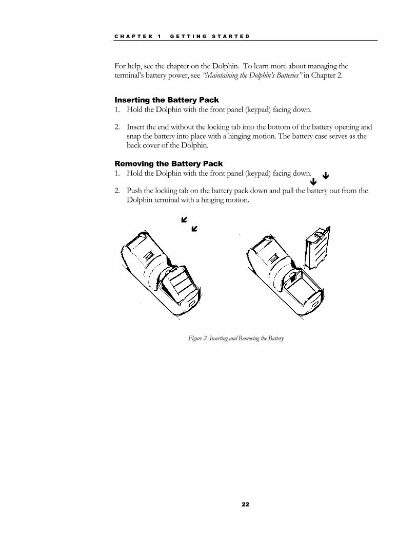
Inserting the Battery Pack 1. Hold the Dolphin with the front panel (keypad) facing down.
2. Insert the end without the locking tab into the bottom of the battery opening and snap the battery into place with a hinging motion. The battery case serves as the back cover of the Dolphin.
Removing the Battery Pack 1. Hold the Dolphin with the front panel (keypad) facing down.
2. Push the locking tab on the battery pack down and pull the battery out from the Dolphin terminal with a hinging motion.
Figure 2 Inserting and Removing the Battery

C H A P T E R 1 G E T T I N G S T A R T E D
23
3 Turning the Dolphin On And Off Turning On the Dolphin 1. Install the charged battery pack in the Dolphin.
2. Hold the Dolphin in the palm of your hand so that you can press the ON/SCAN key easily with your thumb.
3. Press the ON/SCAN key to turn the Dolphin on. Your Dolphin will boot up just like a desktop PC and the title screen for the HHP Demo Application will appear on the display.
If the title screen does not appear on the display of your Dolphin, the HHP Demo Application has been removed from your terminal. Therefore, you will see a DOS prompt on the screen. Example: C:\ or A:\ .
Note: If using the Dolphin for first time or if the terminal has been without a battery pack for more than 30 minutes and you are now inserting a battery, you may receive a CMOS error when the terminal boots up. Don’t worry, the terminal is OK. This simply means that the internal back-up battery needs to be recharged and the date and time need to be reset. To recharge the internal backup battery and reset the date and time, insert a fully charged battery in the Dolphin and then use the DOS date and time function to set the correct date and time. The internal back-up battery requires a minimum of 5 hours of charging time in order to perform and maintain the system as described on page 30.
Turning the Dolphin Off The Dolphin is never actually turned off. To conserve power, the Dolphin goes into “sleep mode” when it is inactive for a programmed period of time as defined by your application. The screen is blank when the Dolphin is in “sleep mode.”
4 Setting the Date and Time Use the DOS date and time function to set the correct date and time for your Dolphin terminal.
To set the date on an alphanumeric Dolphin:
1. Enter <DATE> at the Dolphin’s DOS prompt.
2. Press NUM LOCK to put the Dolphin in numeric mode.
3. Enter the new date <mm-dd-yyyy>.
4. Press <ENTER>.
C H A P T E R 1 G E T T I N G S T A R T E D
24
To set the date on a numeric Dolphin:
1. Press <SHIFT> to put the Dolphin in alpha mode.
2. Enter <DATE> at the Dolphin’s DOS prompt. See the section called Using the Numeric Keypad in Chapter 2 for more information.
3. Press <SHIFT> to put the Dolphin back in numeric mode.
4. Enter the new date <mm-dd-yy>.
5. Press <ENTER>.
To enter the new time, enter <TIME> at the Dolphin’s DOS prompt instead of <DATE> and follow the directions for the Dolphin model you are using.

25
Chapter 2 Dolphin Basics
Describes system features and explains how to use the Dolphin’s keypad, display, batteries, drives and scanner.
C H A P T E R 2 D O L P H I N B A S I C S
26
System Features
CPU The Dolphin’s computing power is provided by a highly integrated AMD ELAN SC310 386SX 33 MHz microprocessor.
Disk Drives The Dolphin contains two disk drives that provide storage for system files, applications, and data. A third drive is also present if you purchase the FLASH expansion option.
Drive A Drive A contains a 120K executable FLASH EEPROM to store system utilities and to initialize the boot process. This drive is read-only and is not usable by the developer/end-user.
Drive C Drive C is an 8MB FLASH virtual hard drive used for program and data storage.
Drive D If you add the expanded memory module to your Dolphin Batch terminal, it will appear as Drive D. Eight (8)MB of additional FLASH memory can be added via the FLASH expansion module. Note: This option is only available for the Dolphin batch and Dolphn iButton terminals.
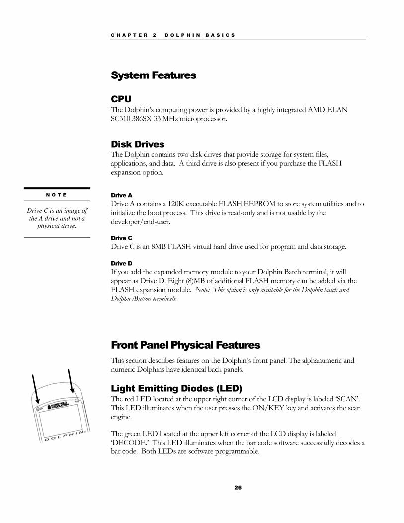
Front Panel Physical Features This section describes features on the Dolphin’s front panel. The alphanumeric and numeric Dolphins have identical back panels.
Light Emitting Diodes (LED) The red LED located at the upper right corner of the LCD display is labeled ‘SCAN’. This LED illuminates when the user presses the ON/KEY key and activates the scan engine.
The green LED located at the upper left corner of the LCD display is labeled ‘DECODE.’ This LED illuminates when the bar code software successfully decodes a bar code. Both LEDs are software programmable.
N O T E
Drive C is an image of the A drive and not a
physical drive.
C H A P T E R 2 D O L P H I N B A S I C S
27
Liquid Crystal Display (LCD) The alphanumeric, scrollable LCD consists of nine rows with 20 character positions per row and 119 x 73 graphics pixels, which are software addressable. The electroluminescent backlight allows you to view the display in low light conditions. To conserve power, the backlight is automatically turned off after 30 seconds. The on/off function and contrast is software programmable.
Note: The ninth row is used for system icons and application-defined icons.
Speaker The Dolphin Batch terminal’s internal speaker emits a sound level of 80dB at 10 cm. The sound level for the Dolphin RF terminal’s external speaker is 90dB at 10 cm.
RF Antenna The Dolphin RF terminal’s 1.36 inch (34.5 mm) antenna is a unity gain, helically-loaded, monopole antenna.
C H A P T E R 2 D O L P H I N B A S I C S
28
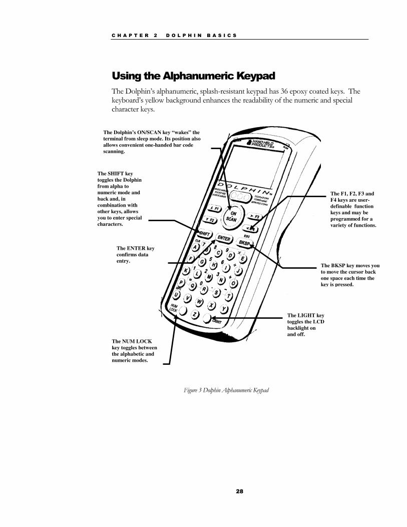
Using the Alphanumeric Keypad The Dolphin’s alphanumeric, splash-resistant keypad has 36 epoxy coated keys. The keyboard’s yellow background enhances the readability of the numeric and special character keys.
Figure 3 Dolphin Alphanumeric Keypad
The Dolphin’s ON/SCAN key “wakes” the terminal from sleep mode. Its position also allows convenient one-handed bar code scanning.
The ENTER key confirms data entry.
The SHIFT key toggles the Dolphin from alpha to numeric mode and back and, in combination with other keys, allows you to enter special characters.
The NUM LOCK key toggles between the alphabetic and numeric modes.
The BKSP key moves you to move the cursor back one space each time the key is pressed.
The LIGHT key toggles the LCD backlight on and off.
The F1, F2, F3 and F4 keys are user-definable function keys and may be programmed for a variety of functions.
C H A P T E R 2 D O L P H I N B A S I C S
29
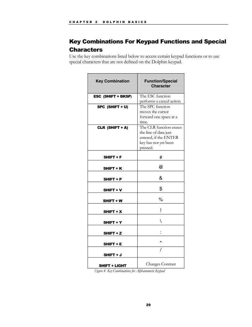
Key Combinations For Keypad Functions and Special Characters Use the key combinations listed below to access certain keypad functions or to use special characters that are not defined on the Dolphin keypad.
Key Combination
Function/Special
Character
ESC (SHIFT + BKSP) The ESC function performs a cancel action.
SPC (SHIFT + U) The SPC function moves the cursor forward one space at a time.
CLR (SHIFT + A) The CLR function erases the line of data just entered, if the ENTER key has not yet been pressed.
SHIFT + F
#
SHIFT + K
@
SHIFT + P
&
SHIFT + V
$
SHIFT + W
%
SHIFT + X
!
SHIFT + Y
\
SHIFT + Z
:
SHIFT + E
*
SHIFT + J /
SHIFT + LIGHT
Changes Contrast
Figure 4 Key Combinations for Alphanumeric Keypad
C H A P T E R 2 D O L P H I N B A S I C S
30
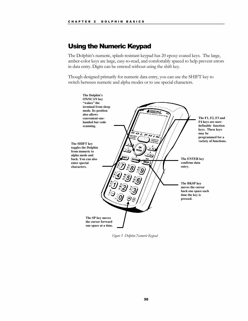
Using the Numeric Keypad The Dolphin’s numeric, splash-resistant keypad has 20 epoxy coated keys. The large, amber-color keys are large, easy-to-read, and comfortably spaced to help prevent errors in data entry. Digits can be entered without using the shift key.
Though designed primarily for numeric data entry, you can use the SHIFT key to switch between numeric and alpha modes or to use special characters.
Figure 5 Dolphin Numeric Keypad
The Dolphin’s ON/SCAN key “wakes” the terminal from sleep mode. Its position also allows convenient one-handed bar code scanning.
The ENTER key confirms data entry.
The SHIFT key toggles the Dolphin from numeric to alpha mode and back. You can also enter special characters.
The BKSP key moves the cursor back one space each time the key is pressed.
The SP key moves the cursor forward one space at a time.
The F1, F2, F3 and F4 keys are user-definable function keys. These keys may be programmed for a variety of functions.
C H A P T E R 2 D O L P H I N B A S I C S
31
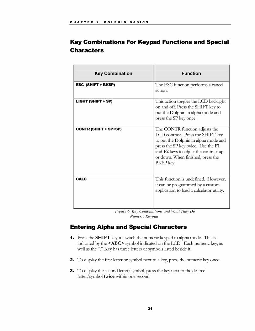
Key Combinations For Keypad Functions and Special Characters
Key Combination
Function
ESC (SHIFT + BKSP) The ESC function performs a cancel
action.
LIGHT (SHIFT + SP) This action toggles the LCD backlight on and off. Press the SHIFT key to put the Dolphin in alpha mode and press the SP key once.
CONTR (SHIFT + SP+SP) The CONTR function adjusts the LCD contrast. Press the SHIFT key to put the Dolphin in alpha mode and press the SP key twice. Use the F1 and F2 keys to adjust the contrast up or down. When finished, press the BKSP key.
CALC This function is undefined. However, it can be programmed by a custom application to load a calculator utility.
Figure 6 Key Combinations and What They Do Numeric Keypad
Entering Alpha and Special Characters
1. Press the SHIFT key to switch the numeric keypad to alpha mode. This is indicated by the <ABC> symbol indicated on the LCD. Each numeric key, as well as the “.” Key has three letters or symbols listed beside it.
2. To display the first letter or symbol next to a key, press the numeric key once.
3. To display the second letter/symbol, press the key next to the desired letter/symbol twice within one second.
C H A P T E R 2 D O L P H I N B A S I C S
32
4. To display the third letter/symbol, press the key next to the desired letter/symbol three times within one second.
For example, to enter a letter “G” into the Dolphin terminal, press the SHIFT key to put the Dolphin in alpha mode. Press the “9” key once and the letter “G” will be entered.
To enter a “T” into the Dolphin terminal, press the SHIFT key to put the Dolphin in alpha mode. Press the “1” key twice and the letter “T” will be entered.
Display Symbols Here is a list of the symbols that can appear on the LCD display of your Dolphin and their meanings.
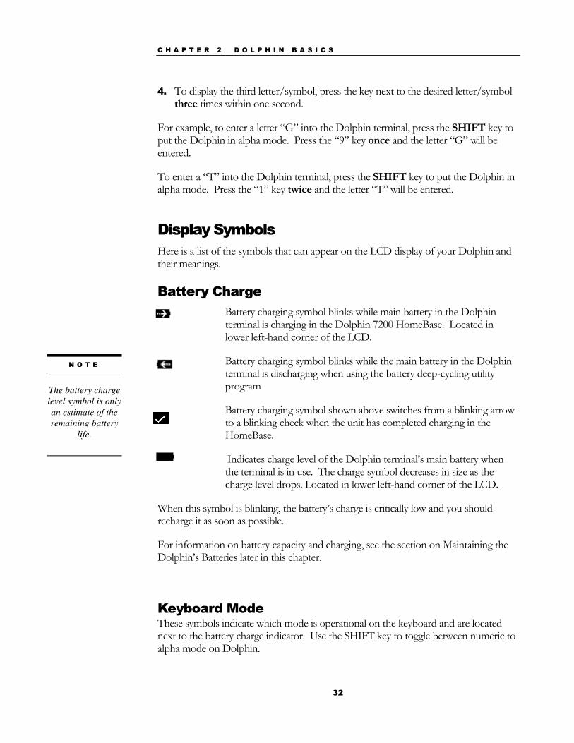
Battery Charge Battery charging symbol blinks while main battery in the Dolphin
terminal is charging in the Dolphin 7200 HomeBase. Located in lower left-hand corner of the LCD.
Battery charging symbol blinks while the main battery in the Dolphin terminal is discharging when using the battery deep-cycling utility program
Battery charging symbol shown above switches from a blinking arrow to a blinking check when the unit has completed charging in the HomeBase.
Indicates charge level of the Dolphin terminal’s main battery when the terminal is in use. The charge symbol decreases in size as the charge level drops. Located in lower left-hand corner of the LCD.
When this symbol is blinking, the battery’s charge is critically low and you should recharge it as soon as possible.
For information on battery capacity and charging, see the section on Maintaining the Dolphin’s Batteries later in this chapter.
Keyboard Mode These symbols indicate which mode is operational on the keyboard and are located next to the battery charge indicator. Use the SHIFT key to toggle between numeric to alpha mode on Dolphin.
N O T E
The battery charge level symbol is only an estimate of the remaining battery
life.

C H A P T E R 2 D O L P H I N B A S I C S
33
Alpha mode -- alphabetic characters are active
Numeric mode -- numeric characters are active
C H A P T E R 2 D O L P H I N B A S I C S
34
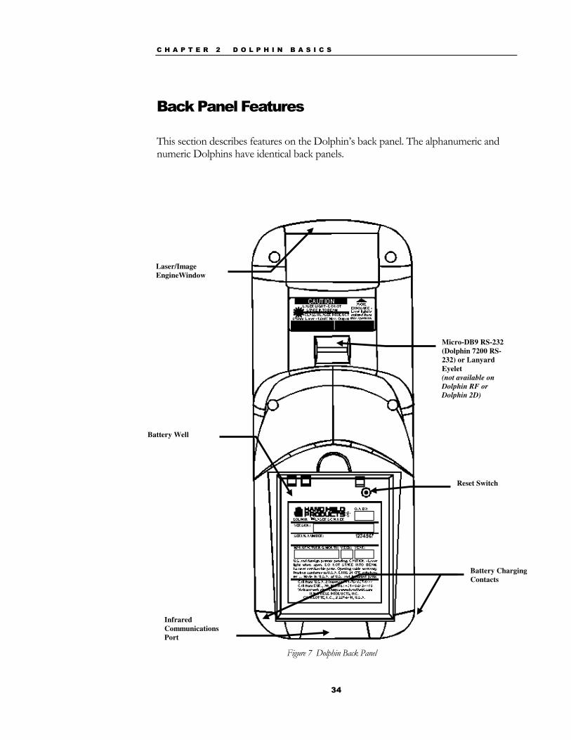
Back Panel Features This section describes features on the Dolphin’s back panel. The alphanumeric and numeric Dolphins have identical back panels.
Laser/Image EngineWindow
Micro-DB9 RS-232 (Dolphin 7200 RS-232) or Lanyard Eyelet (not available on Dolphin RF or Dolphin 2D)
Reset Switch
Battery Well
Battery Charging Contacts
Infrared Communications Port
Figure 7 Dolphin Back Panel
C H A P T E R 2 D O L P H I N B A S I C S
35
Laser Engine The Dolphin 7200 is currently available with four scanning options:
• Standard range • Long range • High density scanning • No scan engine
The laser engine converts reflected light into a digital pattern that represents the bar code data. A clear window covers the laser engine to protect it from dust and dirt.
Image Engine The Dolphin 7200 2D terminal is available with the following imaging options:
• Standard image engine: scans 2 to 9 in. (5 to 23 cm) • High-Density: scans 2 to 4 in. (5 to 12 cm) • LX image engine: scans 2 to 15 in. (5 to 38 cm) on low density bar codes
Lanyard Eyelet for Optional Wrist Strap This feature allows a strap to be attached to the Dolphin terminal so that it can be conveniently secured around the wrist or hooked on to a belt. Not available on the Dolphin 7200 RF, the Dolphin 7200 2D or the Dolphin 7200 RS-232 terminals.
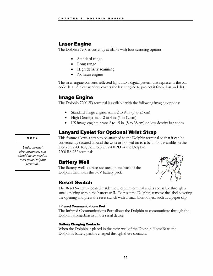
Battery Well The Battery Well is a recessed area on the back of the Dolphin that holds the 3.6V battery pack.
Reset Switch The Reset Switch is located inside the Dolphin terminal and is accessible through a small opening within the battery well. To reset the Dolphin, remove the label covering the opening and press the reset switch with a small blunt object such as a paper clip.
Infrared Communications Port The Infrared Communications Port allows the Dolphin to communicate through the Dolphin HomeBase to a host serial device.
Battery Charging Contacts When the Dolphin is placed in the main well of the Dolphin HomeBase, the Dolphin’s battery pack is charged through these contacts.
N O T E
Under normal
circumstances, you should never need to reset your Dolphin
terminal.
C H A P T E R 2 D O L P H I N B A S I C S
36
Maintaining the Dolphin’s Batteries CAUTION: Use only the 3.6V battery packs provided by Hand Held Products. The use of any other battery pack in the Dolphin 7200 terminal will void your warranty and may result in damage to the Dolphin terminal or battery.
There are two batteries in the Dolphin:
Internal NiMH Backup Battery Located inside the Dolphin, this battery backs up the RAM and clock when the NiMH main battery is discharged or removed from the terminal.
NiMH Battery Pack The battery pack is the primary power source for operating the Dolphin.
Internal NiMH Backup Battery The Dolphin’s internal backup battery prevents the terminal from being reset if you need to remove and replace the main battery pack. The battery retains RAM data and allows the real-time clock to remain operational for up to 30 minutes when the battery pack is removed. If the internal back-up battery becomes discharged of power, it requires a minimum of 5 hours of charging time in order to perform and maintain the system as described above.
The internal backup battery is charged by the Dolphin’s main battery pack. If the terminal is left without the main battery pack for more than 30 minutes, the internal backup battery needs to be recharged.
Note: Data and programs on Drives C and D remain safe even if the internal backup battery fails. However, you must reset the real-time clock using the DOS Time and Date function.
Follow these guidelines to maximize the life of the Dolphin’s backup battery:
• Keep a charged NiMH battery pack in the Dolphin. The internal battery will prematurely discharge if there is not at least a partially charged battery in the terminal.
• Put the Dolphin in the HomeBase when the terminal is not in use.
N O T E
Return the Dolphin to an authorized service
center when the internal battery needs
to be replaced.
N O T E
Never insert the Dolphin into the
HomeBase without the NiMH main battery pack
inserted.
C H A P T E R 2 D O L P H I N B A S I C S
37
NiMH Battery Pack The 3.6V, 1500 mAh Nickel-Metal-Hydride (NiMH) battery pack is the primary power source for the Dolphin. Other Nickel-Metal-Hydride batteries may be approved by Hand Held Products, Inc. to work with your Dolphin. Contact Hand Held for more information.
The 1500 mAh NiMH battery is designed to operate in temperature range of –10 to 50 °C (14 to 122° F). For maximum performance, charge the batteries between 10 and 35 °C (50 and 95° F).
WARNING: Although the Dolphin 7200 terminal is received with the battery inserted, it is NOT ready for charging and/or deep-cycling. Remove the plastic insulator located between the terminal and battery connectors. Failure to remove the insulator may result in damages to the terminal.
Performance specifications for a fully charged 1500 mAh NiMH battery (using power management function calls within application):
Up to 20 hours of usage in a Dolphin Batch terminal with a full battery charge
Up to 10 hours of usage in a Dolphin RF terminal with a full battery charge
Up to 20 hours of usage in a Dolphin 2D terminal with a full battery charge
Keep a charged battery pack in the Dolphin at all times to conserve the internal back-up battery. When you remove a battery pack, insert another battery pack in the Dolphin. The internal battery will prematurely discharge if there is not at least a partially charged battery in the terminal.
Servicing the Battery Pack For maximum battery life, Hand Held Products recommends that you deep-cycle the battery twice before initial use. It is also recommended that you service, or calibrate the battery once per month. To deep cycle, insert the battery into the HomeBase auxiliary battery well. Then, push and hold the Service Aux Batt button for at least 4 seconds. For more information, see the section on the Service Aux Batt feature of the HomeBase in Chapter 7.
You may also deep cycle the battery using the CycleBat battery utility conditioning software which is available from the Partners area of the Hand Held Products website, http://www.hhp.com/. More information on this utility is available from the help file that comes with the software.
N O T E
Keep a charged
battery pack in the Dolphin at all times to conserve the internal
back-up battery.
N O T E
For maximum battery life, Hand Held
Products recommends that you deep-cycle (service) the battery
twice before initial use and then, once a month
thereafter.

C H A P T E R 2 D O L P H I N B A S I C S
38
Charging the Battery Pack You can recharge an individual battery pack using the auxiliary battery well of the Dolphin HomeBase, or the Dolphin 10-Slot Multiple Battery Charger. Both accessories use a charging method that senses when the battery pack is fully charged and then drops to a trickle charge to keep the battery pack at full capacity.
For more details, see the section on Charging Batteries in the HomeBase in Chapter 7.
Storing Batteries To maintain top performance from batteries, follow the guidelines below when storing them:
• Avoid storing batteries outside of the specified range of -4 to 104° F (-20 to 40°C) or in extremely high humidity.
• For prolonged storage, do not keep batteries stored in the terminal. • During long-term storage, battery deactivation may tend to occur which
may cause charging to stop early during recharging after storage. Charging and discharging the battery several times can handle this issue. Also, the first charging after prolonged storage may yield a lower than normal capacity. While this will vary depending on the storage conditions, charging and discharging the battery several times will almost completely restore capacity.

39
Chapter 3 Dolphin® 7200 RF Handheld Computer
C H A P T E R 3 D O L P H I N 7 2 0 0 R F H A N D H E L D C O M P U T E R
40
About the Dolphin 7200 RF Handheld Computer The Dolphin 7200 RF® terminal integrates the basic functionality of the Batch terminal with an 802.11b or a WLIF™ interface that allows the terminal to communicate with a host computer via a wireless local area network (WLAN). Both radio options operate in the 2.4 GHz frequency band. Terminal emulation software and keypad overlays for IBM 3270, IBM 5250 and DEC VT100/220 emulation are available for both radio options. The terminal’s DOS compatible 386 microprocessor is easy to program and developers can create wireless applications linked to a host PC, using RF Simplicity® and MS Visual Basic™.
Refer to Chapters 1 and 2 in this manual for more on basic operation of the Dolphin terminal and accessories available.
802.11b-Compliant Dolphin 7200 RF Terminal The 802.11b-compliant Dolphin 7200 RF incorporates a Cisco® 802.11b Micro-ISA radio. The radio uses direct sequence spread spectrum (DSSS) technology, which spreads its signal continuously over a wide frequency band, and provides an Ethernet-like data rate of up to 11 megabits per second. The radio may also provide up to 128-bit Wired Equivalent Privacy (WEP) encryption. WEP is used to encrypt and decrypt data signals transmitted between Wireless LAN (WLAN) devices. It is an optional security encryption mechanism defined within the 802.11 standard that makes a wireless LAN link as secure as a traditional wired link. The optional WEP security mechanism is available with 128-bit or 40-bit encryption.
Dolphin 7200 RF is interoperable with other 802.11b compliant products to allow network expansion as needed. It can be connected to other devices, such as printers and PCs via PC-card adapters.
C H A P T E R 3 D O L P H I N 7 2 0 0 R F H A N D H E L D C O M P U T E R
41
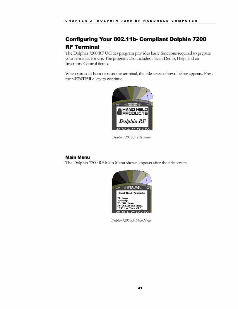
Configuring Your 802.11b- Compliant Dolphin 7200 RF Terminal The Dolphin 7200 RF Utilities program provides basic functions required to prepare your terminals for use. The program also includes a Scan Demo, Help, and an Inventory Control demo.
When you cold-boot or reset the terminal, the title screen shown below appears. Press the <ENTER> key to continue.
Dolphin 7200 RF Title Screen
Main Menu The Dolphin 7200 RF Main Menu shown appears after the title screen:
Dolphin 7200 RF Main Menu
C H A P T E R 3 D O L P H I N 7 2 0 0 R F H A N D H E L D C O M P U T E R
42
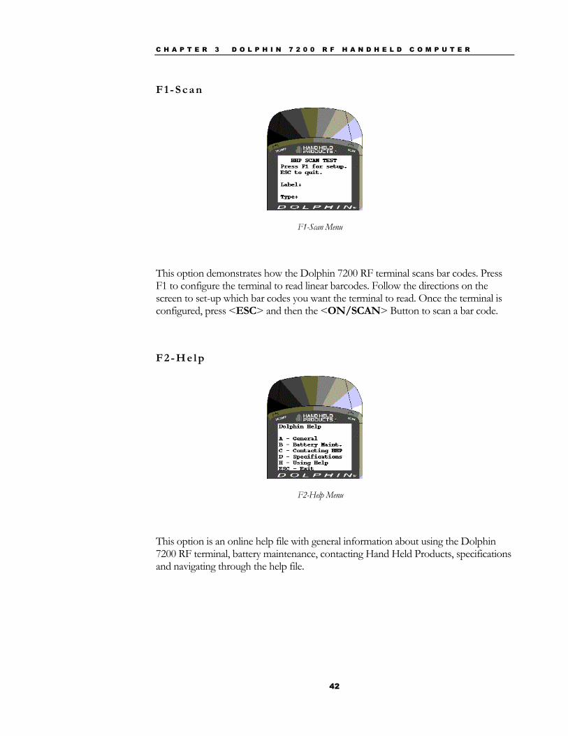
F 1 - S c a n
F1-Scan Menu
This option demonstrates how the Dolphin 7200 RF terminal scans bar codes. Press F1 to configure the terminal to read linear barcodes. Follow the directions on the screen to set-up which bar codes you want the terminal to read. Once the terminal is configured, press <ESC> and then the <ON/SCAN> Button to scan a bar code.
F 2 - H e l p
F2-Help Menu
This option is an online help file with general information about using the Dolphin 7200 RF terminal, battery maintenance, contacting Hand Held Products, specifications and navigating through the help file.

C H A P T E R 3 D O L P H I N 7 2 0 0 R F H A N D H E L D C O M P U T E R
43
F 3 - H H P D e m o
F3-HHP Demo
The HHP Demo is a sample inventory control program.
F 4 - U t i l i t i e s M e n u
F4-Utility Menu
C H A P T E R 3 D O L P H I N 7 2 0 0 R F H A N D H E L D C O M P U T E R
44
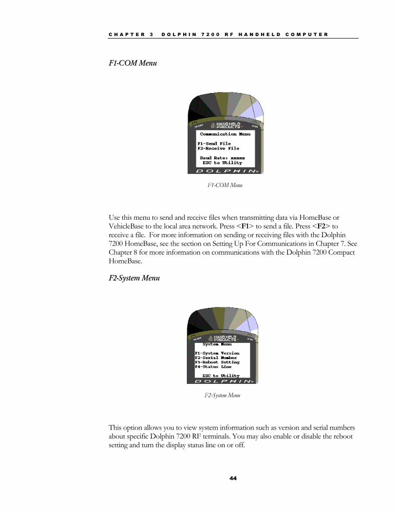
F1-COM Menu
F1-COM Menu
Use this menu to send and receive files when transmitting data via HomeBase or VehicleBase to the local area network. Press <F1> to send a file. Press <F2> to receive a file. For more information on sending or receiving files with the Dolphin 7200 HomeBase, see the section on Setting Up For Communications in Chapter 7. See Chapter 8 for more information on communications with the Dolphin 7200 Compact HomeBase.
F2-System Menu
F2-System Menu
This option allows you to view system information such as version and serial numbers about specific Dolphin 7200 RF terminals. You may also enable or disable the reboot setting and turn the display status line on or off.
C H A P T E R 3 D O L P H I N 7 2 0 0 R F H A N D H E L D C O M P U T E R
45
F3-DOS Prompt
Press <F3> to exit to the DOS prompt.
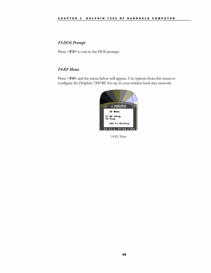
F4-RF Menu
Press <F4> and the menu below will appear. Use options from this menu to configure the Dolphin 7200 RF for use in your wireless local area network.
F4-RF Menu
C H A P T E R 3 D O L P H I N 7 2 0 0 R F H A N D H E L D C O M P U T E R
46
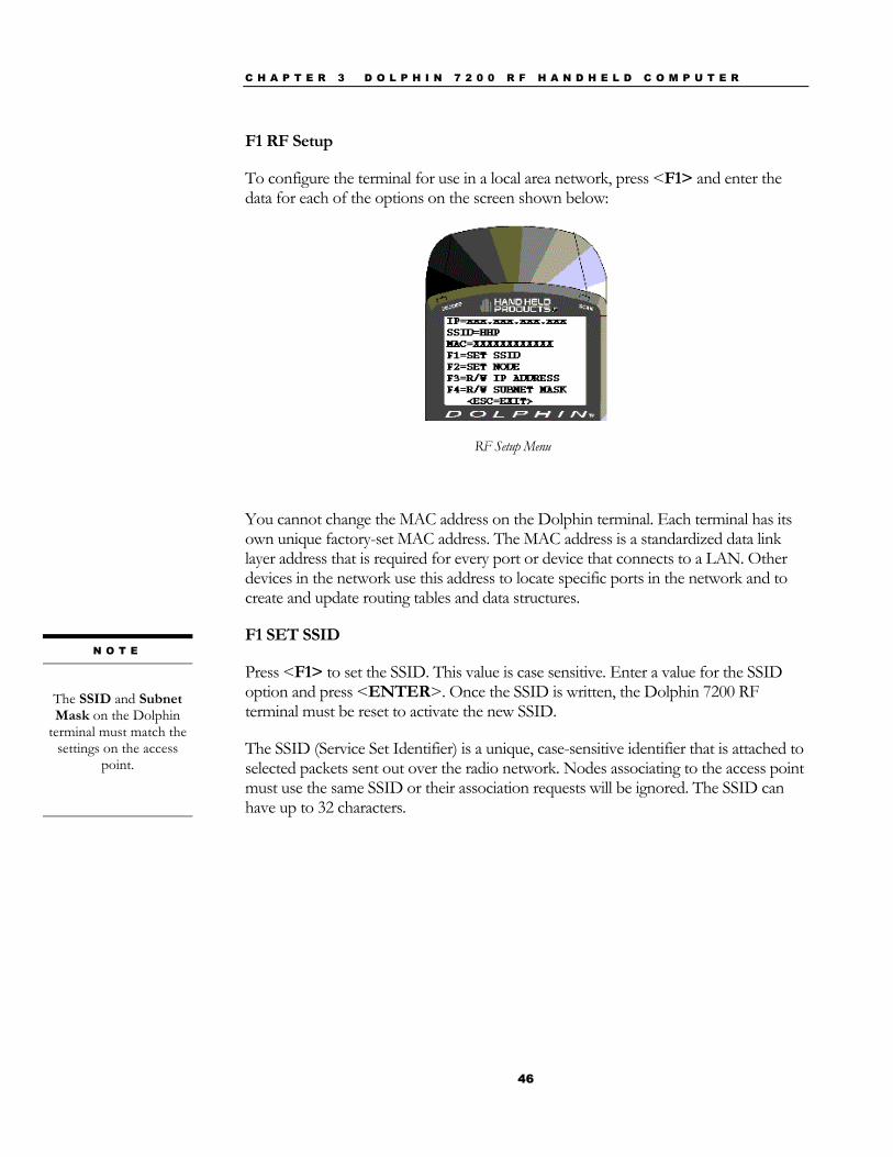
F1 RF Setup
To configure the terminal for use in a local area network, press <F1> and enter the data for each of the options on the screen shown below:
RF Setup Menu
You cannot change the MAC address on the Dolphin terminal. Each terminal has its own unique factory-set MAC address. The MAC address is a standardized data link layer address that is required for every port or device that connects to a LAN. Other devices in the network use this address to locate specific ports in the network and to create and update routing tables and data structures.
F1 SET SSID
Press <F1> to set the SSID. This value is case sensitive. Enter a value for the SSID option and press <ENTER>. Once the SSID is written, the Dolphin 7200 RF terminal must be reset to activate the new SSID.
The SSID (Service Set Identifier) is a unique, case-sensitive identifier that is attached to selected packets sent out over the radio network. Nodes associating to the access point must use the same SSID or their association requests will be ignored. The SSID can have up to 32 characters.
N O T E
The SSID and Subnet Mask on the Dolphin
terminal must match the settings on the access
point.
C H A P T E R 3 D O L P H I N 7 2 0 0 R F H A N D H E L D C O M P U T E R
47
F2 SET NODE
Press F2 to set a system name for the Dolphin 7200 RF terminal. Enter a value for the NODE option and press <ENTER>. Once the NODE is written, the Dolphin 7200 RF terminal must be reset to activate the new NODE. The name should describe the location or principal users of the Access Point.
F3 R/W IP ADDRESS
Press F3 to enter the IP address. Enter a value for the IP Address option and press <ENTER>. Once the IP Address is written, the Dolphin 7200 RF terminal must be reset to activate the new IP Address.
The IP address is a 32-bit address assigned to hosts using TCP/IP. An IP address belongs to one of five classes (A, B, C, D, or E) and is written as four octets separated by periods (dotted decimal format). Each address consists of a network number, an optional sub network number, and a host number.
F4 R/W SUBNET MASK
Press F4 to enter the Subnet Mask. Enter a value for the Subnet Mask option and press <ENTER>. Once the Subnet Mask Address is written, the Dolphin 7200 RF terminal must be reset to activate the new Subnet Mask.
The Subnet Mask is the portion of an IP address that is specified as the sub network by the subnet mask.
N O T E
Reset the Dolphin
terminal by pressing and releasing the
<SHIFT>, <ON/SCAN>
and <BKSP> keys. All three keys must be held down and released
at the same time.
N O T E
The Dolphin need not
be reset after each configuration change, but can be done once
all configurations changes have been
made.

C H A P T E R 3 D O L P H I N 7 2 0 0 R F H A N D H E L D C O M P U T E R
48
Setting WEP Modes And Keys On The 802.11b Radio Card
This section describes how to set WEP (Wired Equivalent Privacy) modes and keys on the Cisco® 802.11b radio card.
WEP is used to encrypt and decrypt data signals transmitted between Wireless LAN (WLAN) devices. WEP is an optional IEEE 802.11 feature used to provide data confidentiality that is equivalent to the confidentiality of a wired LAN that does not employ crypto techniques to enhance privacy. WEP makes a wireless LAN link as secure as a wired link.
The wep.bat utility is used to set WEP modes and keys for the Cisco® 802.11b radio card. The wep.bat file uses three files:
wepdos.exe – an executable file that configures WEP values for the Cisco radio
keys.exe – an executable file that calls the functions for setting WEP values
cscpkt.ini – a configuration file for the Cisco radio
All four files are located in the Dolphin c:\rf directory that is part of the stackcsc.exe file.
If the user will be setting WEP keys using the batch mode, the user must create a keys.txt file using a text editor such as Notepad and then copy it to the c:\rf directory. This file will contain the encryption keys used when operating in WEP mode. For obvious security reasons, this file will be automatically deleted upon running the wep.bat utility. HHP recommends that you verify that the keys.txt file has been deleted.
Refer to the Cisco documentation for complete descriptions of the various WEP modes. The current radio card may not support some modes.
C H A P T E R 3 D O L P H I N 7 2 0 0 R F H A N D H E L D C O M P U T E R
49
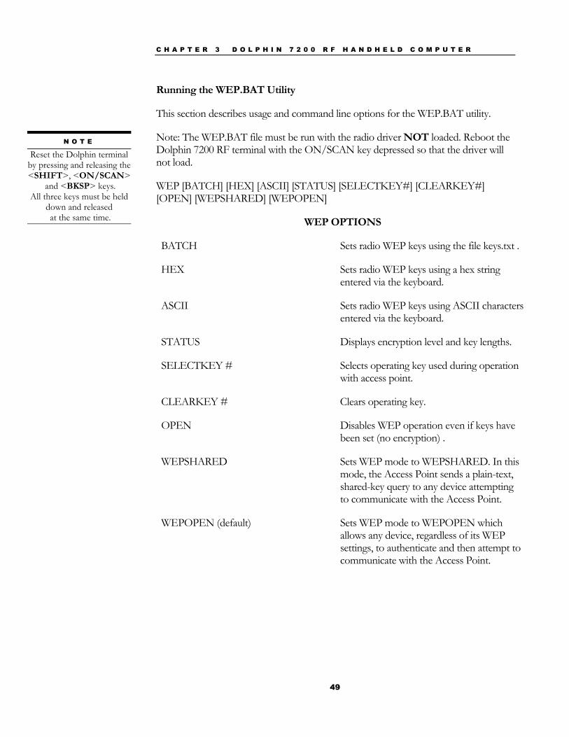
Running the WEP.BAT Utility
This section describes usage and command line options for the WEP.BAT utility.
Note: The WEP.BAT file must be run with the radio driver NOT loaded. Reboot the Dolphin 7200 RF terminal with the ON/SCAN key depressed so that the driver will not load.
WEP [BATCH] [HEX] [ASCII] [STATUS] [SELECTKEY#] [CLEARKEY#] [OPEN] [WEPSHARED] [WEPOPEN]
WEP OPTIONS
BATCH Sets radio WEP keys using the file keys.txt .
HEX Sets radio WEP keys using a hex string entered via the keyboard.
ASCII Sets radio WEP keys using ASCII characters entered via the keyboard.
STATUS Displays encryption level and key lengths.
SELECTKEY # Selects operating key used during operation with access point.
CLEARKEY # Clears operating key.
OPEN Disables WEP operation even if keys have been set (no encryption) .
WEPSHARED Sets WEP mode to WEPSHARED. In this mode, the Access Point sends a plain-text, shared-key query to any device attempting to communicate with the Access Point.
WEPOPEN (default) Sets WEP mode to WEPOPEN which allows any device, regardless of its WEP settings, to authenticate and then attempt to communicate with the Access Point.
N O T E
Reset the Dolphin terminal by pressing and releasing the <SHIFT>, <ON/SCAN>
and <BKSP> keys. All three keys must be held
down and released at the same time.
C H A P T E R 3 D O L P H I N 7 2 0 0 R F H A N D H E L D C O M P U T E R
50
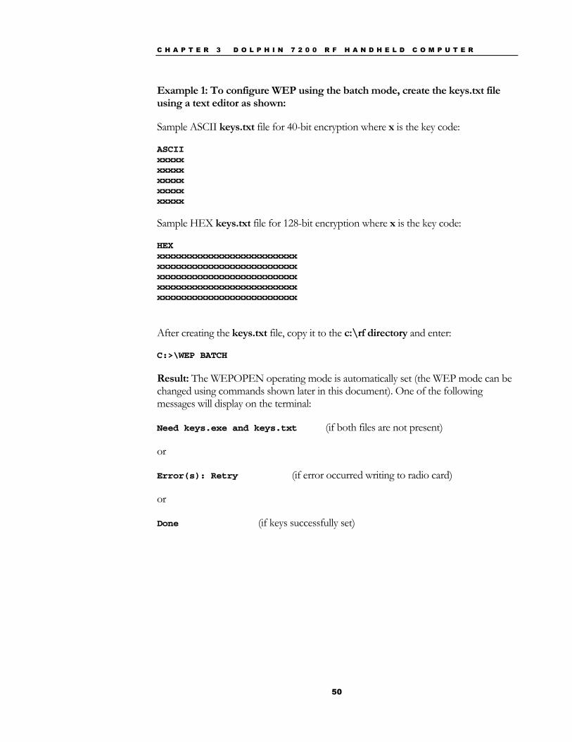
Example 1: To configure WEP using the batch mode, create the keys.txt file using a text editor as shown:
Sample ASCII keys.txt file for 40-bit encryption where x is the key code:
ASCII xxxxx xxxxx xxxxx xxxxx xxxxx
Sample HEX keys.txt file for 128-bit encryption where x is the key code:
HEX xxxxxxxxxxxxxxxxxxxxxxxxxx xxxxxxxxxxxxxxxxxxxxxxxxxx xxxxxxxxxxxxxxxxxxxxxxxxxx xxxxxxxxxxxxxxxxxxxxxxxxxx xxxxxxxxxxxxxxxxxxxxxxxxxx
After creating the keys.txt file, copy it to the c:\rf directory and enter:
C:>\WEP BATCH
Result: The WEPOPEN operating mode is automatically set (the WEP mode can be changed using commands shown later in this document). One of the following messages will display on the terminal:
Need keys.exe and keys.txt (if both files are not present)
or
Error(s): Retry (if error occurred writing to radio card)
or
Done (if keys successfully set)
C H A P T E R 3 D O L P H I N 7 2 0 0 R F H A N D H E L D C O M P U T E R
51
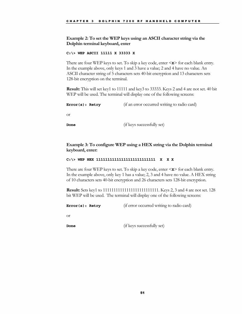
Example 2: To set the WEP keys using an ASCII character string via the Dolphin terminal keyboard, enter
C:\> WEP ASCII 11111 X 33333 X
There are four WEP keys to set. To skip a key code, enter <X> for each blank entry. In the example above, only keys 1 and 3 have a value; 2 and 4 have no value. An ASCII character string of 5 characters sets 40-bit encryption and 13 characters sets 128-bit encryption on the terminal.
Result: This will set key1 to 11111 and key3 to 33333. Keys 2 and 4 are not set. 40 bit WEP will be used. The terminal will display one of the following screens:
Error(s): Retry (if an error occurred writing to radio card)
or
Done (if keys successfully set)
Example 3: To configure WEP using a HEX string via the Dolphin terminal keyboard, enter:
C:\> WEP HEX 11111111111111111111111111 X X X
There are four WEP keys to set. To skip a key code, enter <X> for each blank entry. In the example above, only key 1 has a value; 2, 3 and 4 have no value. A HEX string of 10 characters sets 40-bit encryption and 26 characters sets 128-bit encryption.
Result: Sets key1 to 11111111111111111111111111. Keys 2, 3 and 4 are not set. 128 bit WEP will be used. The terminal will display one of the following screens:
Error(s): Retry (if error occurred writing to radio card)
or
Done (if keys successfully set)
C H A P T E R 3 D O L P H I N 7 2 0 0 R F H A N D H E L D C O M P U T E R
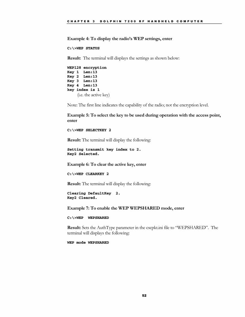
52
Example 4: To display the radio’s WEP settings, enter
C:\>WEP STATUS
Result: The terminal will displays the settings as shown below:
WEP128 encryption Key 1 Len:13 Key 2 Len:13 Key 3 Len:13 Key 4 Len:13 key index is 1
(i.e. the active key)
Note: The first line indicates the capability of the radio; not the encryption level.
Example 5: To select the key to be used during operation with the access point, enter
C:\>WEP SELECTKEY 2
Result: The terminal will display the following:
Setting transmit key index to 2. Key2 Selected.
Example 6: To clear the active key, enter
C:\>WEP CLEARKEY 2
Result: The terminal will display the following:
Clearing DefaultKey 2. Key2 Cleared.
Example 7: To enable the WEP WEPSHARED mode, enter
C:\>WEP WEPSHARED
Result: Sets the AuthType parameter in the cscpkt.ini file to “WEPSHARED”. The terminal will displays the following:
WEP mode WEPSHARED
C H A P T E R 3 D O L P H I N 7 2 0 0 R F H A N D H E L D C O M P U T E R
53
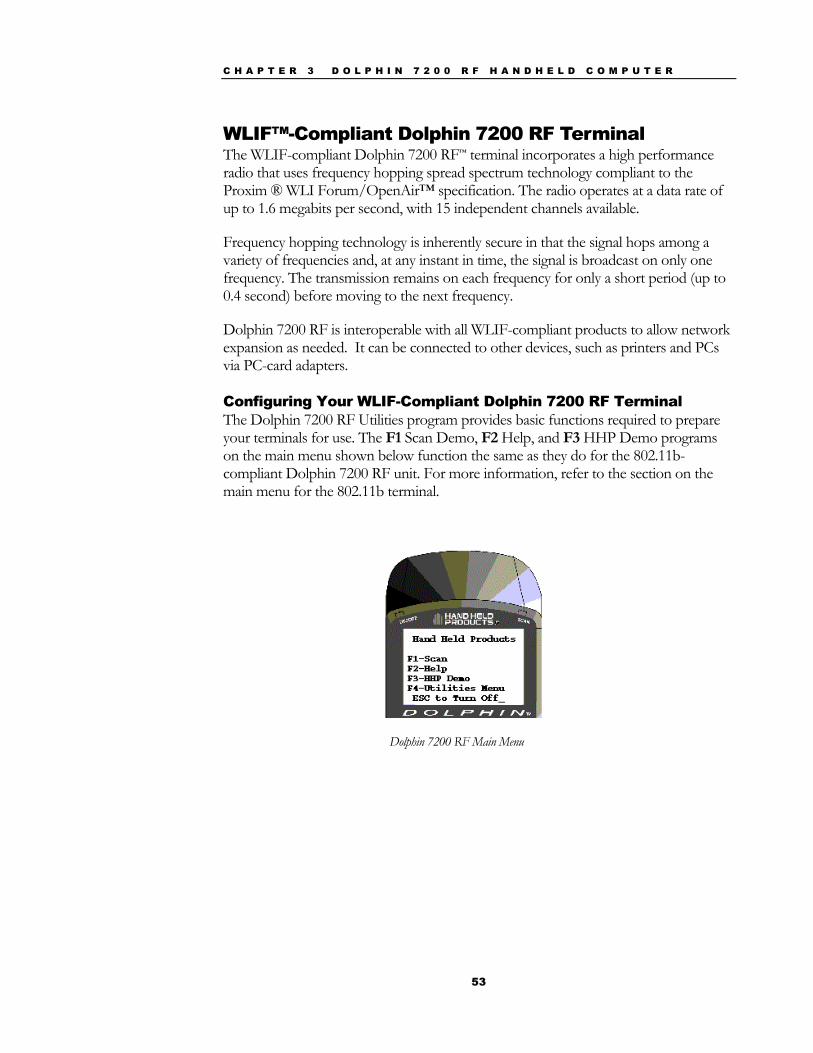
WLIF™-Compliant Dolphin 7200 RF Terminal The WLIF-compliant Dolphin 7200 RF™ terminal incorporates a high performance radio that uses frequency hopping spread spectrum technology compliant to the Proxim ® WLI Forum/OpenAir™ specification. The radio operates at a data rate of up to 1.6 megabits per second, with 15 independent channels available.
Frequency hopping technology is inherently secure in that the signal hops among a variety of frequencies and, at any instant in time, the signal is broadcast on only one frequency. The transmission remains on each frequency for only a short period (up to 0.4 second) before moving to the next frequency.
Dolphin 7200 RF is interoperable with all WLIF-compliant products to allow network expansion as needed. It can be connected to other devices, such as printers and PCs via PC-card adapters.
Configuring Your WLIF-Compliant Dolphin 7200 RF Terminal The Dolphin 7200 RF Utilities program provides basic functions required to prepare your terminals for use. The F1 Scan Demo, F2 Help, and F3 HHP Demo programs on the main menu shown below function the same as they do for the 802.11b-compliant Dolphin 7200 RF unit. For more information, refer to the section on the main menu for the 802.11b terminal.
Dolphin 7200 RF Main Menu
C H A P T E R 3 D O L P H I N 7 2 0 0 R F H A N D H E L D C O M P U T E R
54
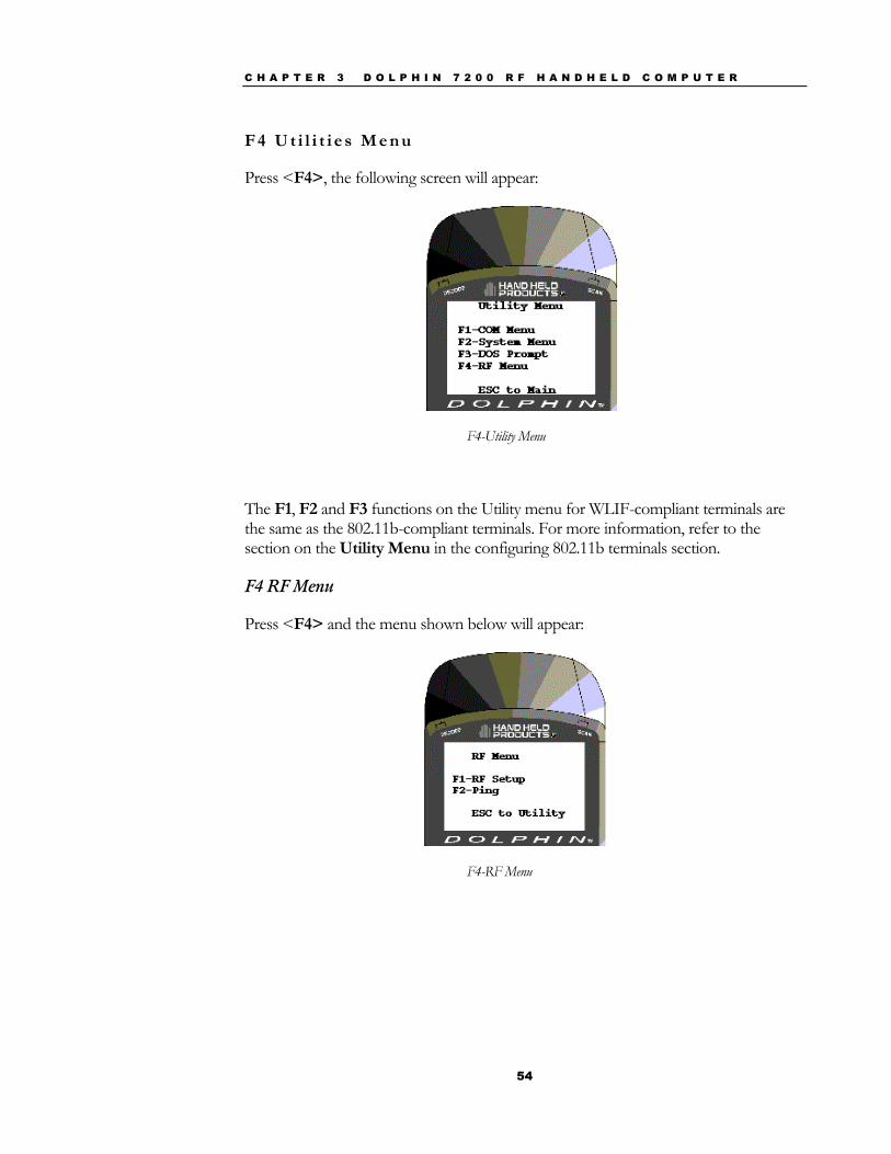
F 4 U t i l i t i e s M e n u
Press <F4>, the following screen will appear:
F4-Utility Menu
The F1, F2 and F3 functions on the Utility menu for WLIF-compliant terminals are the same as the 802.11b-compliant terminals. For more information, refer to the section on the Utility Menu in the configuring 802.11b terminals section.
F4 RF Menu
Press <F4> and the menu shown below will appear:
F4-RF Menu
C H A P T E R 3 D O L P H I N 7 2 0 0 R F H A N D H E L D C O M P U T E R
55
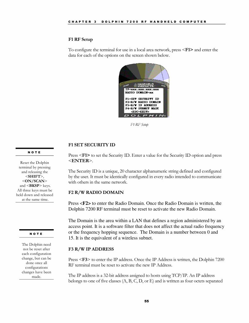
F1 RF Setup
To configure the terminal for use in a local area network, press <F1> and enter the data for each of the options on the screen shown below.
F1-RF Setup
F1 SET SECURITY ID
Press <F1> to set the Security ID. Enter a value for the Security ID option and press <ENTER>.
The Security ID is a unique, 20 character alphanumeric string defined and configured by the user. It must be identically configured in every radio intended to communicate with others in the same network.
F2 R/W RADIO DOMAIN
Press <F2> to enter the Radio Domain. Once the Radio Domain is written, the Dolphin 7200 RF terminal must be reset to activate the new Radio Domain. The Domain is the area within a LAN that defines a region administered by an access point. It is a software filter that does not affect the actual radio frequency or the frequency hopping sequence. The Domain is a number between 0 and 15. It is the equivalent of a wireless subnet. F3 R/W IP ADDRESS
Press <F3> to enter the IP address. Once the IP Address is written, the Dolphin 7200 RF terminal must be reset to activate the new IP Address.
The IP address is a 32-bit address assigned to hosts using TCP/IP. An IP address belongs to one of five classes (A, B, C, D, or E) and is written as four octets separated
N O T E
Reset the Dolphin
terminal by pressing and releasing the
<SHIFT>, <ON/SCAN>
and <BKSP> keys. All three keys must be held down and released
at the same time.
N O T E
The Dolphin need not be reset after
each configuration change, but can be
done once all configurations
changes have been made.
C H A P T E R 3 D O L P H I N 7 2 0 0 R F H A N D H E L D C O M P U T E R
56
by periods (dotted decimal format). Each address consists of a network number, an optional sub network number, and a host number.
F4 R/W SUBNET MASK
Press <F4> to enter the Subnet Mask. Once the Subnet Mask is written, the Dolphin 7200 RF terminal must be reset to activate the new Subnet Mask.
The Subnet Mask is the portion of an IP address that is specified as the sub network by the subnet mask.
Dolphin 7200 RF Peripherals Peripherals for building wireless networks using Dolphin 7200 RF terminals include PC cards, access points, and antennas. Peripherals available for 802.11b Direct Sequence radio networks are Wi-Fi™ certified; peripherals for Frequency Hopping radio networks are OpenAir® compliant.
PC Cards PC cards provide devices such has laptop and desktop computers with wireless connectivity to the RF network.
Access Points Access Points link a wired network to a wireless Dolphin 7200 RF handheld computer network.
There are a wide range of mounting brackets and antenna cabling options available to provide wireless coverage for a customer’s entire facility. Access points can be easily configured and managed from a server or using a web browser or telnet session.
See your Access Point user’s guide for more information.
Antennas Various antenna options are available to extend the range of access points in your 802.11b or WLIF wireless network. Antennas available include:
• Omnidirectional • Patch • Yagi
Host Connectivity HHP offers several host connectivity options for Dolphin 7200 RF wireless LAN solutions. Direct Connect TN Client software is a thick-client solution that connects Dolphin 7200 RF™ computers directly to host applications via TN3270, TN5250 or TNVT terminal emulation using industry-standard TCP/IP protocol. Another option
N O T E
The Security ID, Radio
Domain and Subnet Mask on the Dolphin terminal
must match the settings on the access point.
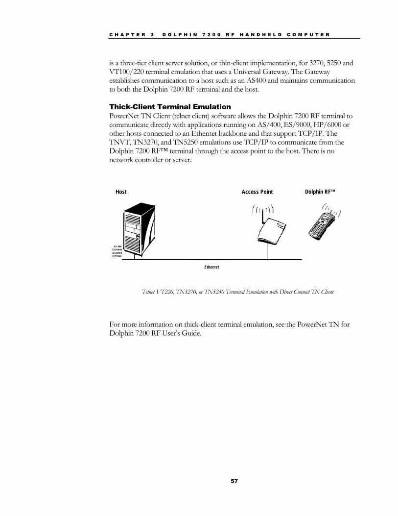
C H A P T E R 3 D O L P H I N 7 2 0 0 R F H A N D H E L D C O M P U T E R
57
is a three-tier client server solution, or thin-client implementation, for 3270, 5250 and VT100/220 terminal emulation that uses a Universal Gateway. The Gateway establishes communication to a host such as an AS400 and maintains communication to both the Dolphin 7200 RF terminal and the host.
Thick-Client Terminal Emulation PowerNet TN Client (telnet client) software allows the Dolphin 7200 RF terminal to communicate directly with applications running on AS/400, ES/9000, HP/6000 or other hosts connected to an Ethernet backbone and that support TCP/IP. The TNVT, TN3270, and TN5250 emulations use TCP/IP to communicate from the Dolphin 7200 RF™ terminal through the access point to the host. There is no network controller or server.
Host
Ethernet
Access Point Dolphin RF™
AS 400ES/9000RS/8000HP9000
Telnet VT220, TN3270, or TN5250 Terminal Emulation with Direct Connect TN Client
For more information on thick-client terminal emulation, see the PowerNet TN for Dolphin 7200 RF User’s Guide.
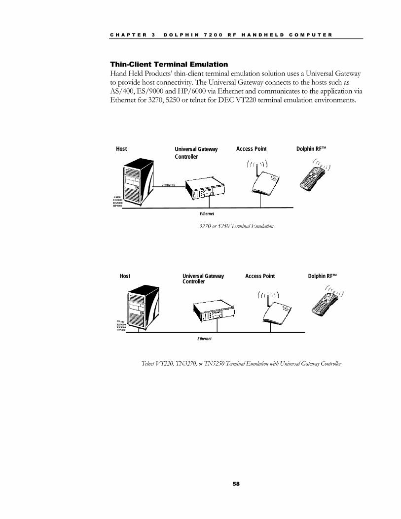
C H A P T E R 3 D O L P H I N 7 2 0 0 R F H A N D H E L D C O M P U T E R
58
Thin-Client Terminal Emulation Hand Held Products’ thin-client terminal emulation solution uses a Universal Gateway to provide host connectivity. The Universal Gateway connects to the hosts such as AS/400, ES/9000 and HP/6000 via Ethernet and communicates to the application via Ethernet for 3270, 5250 or telnet for DEC VT220 terminal emulation environments.
3270 or 5250 Terminal Emulation
Host Universal GatewayController
Ethernet
Access Point Dolphin RF™
AS 400ES/9000RS/8000HP9000
Telnet VT220, TN3270, or TN5250 Terminal Emulation with Universal Gateway Controller
Host Universal GatewayController
Ethernet
Access Point Dolphin RF™
AS 400ES/9000RS/8000HP9000
v.23/v.35
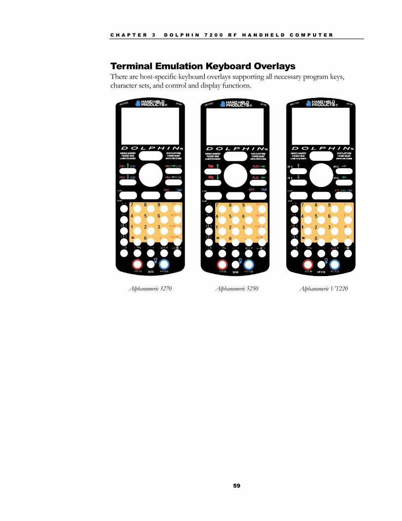
C H A P T E R 3 D O L P H I N 7 2 0 0 R F H A N D H E L D C O M P U T E R
59
Terminal Emulation Keyboard Overlays There are host-specific keyboard overlays supporting all necessary program keys, character sets, and control and display functions.
Alphanumeric 3270
Alphanumeric 5250
Alphanumeric VT220
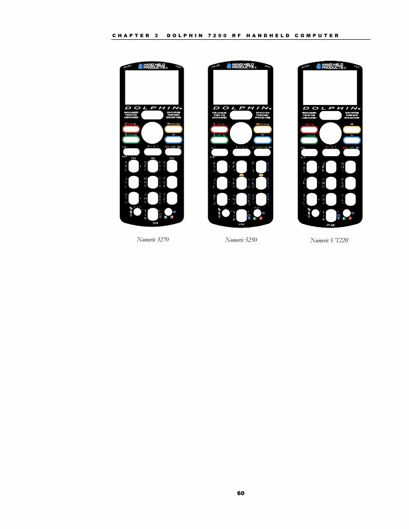
C H A P T E R 3 D O L P H I N 7 2 0 0 R F H A N D H E L D C O M P U T E R
60
Numeric 3270
Numeric 5250
Numeric VT220
61
Chapter 4 Dolphin® 7200 with iButton Reader Handheld Computer Describes the iButton reader and how to use it.
C H A P T E R 4 A B O U T T H E D O L P H I N 7 2 0 0 W I T H I B U T T O N R E A D E R H A N D H E L D C O M P U T E R
62
About Dolphin with iButton Reader Handheld Computer The Dolphin with iButton Reader handheld computer integrates the basic functionality of the Dolphin Batch terminal with iButton™ technology that allows the terminal to read and write data from and to iButtons.
The iButton reader is a function and feature extension of the Batch terminal. Like the batch versions, Dolphin iB can be equipped with up to 8 Mb of flash memory and will support all scan engine versions available for the Dolphin platform. Refer to Chapters 1 and 2 in this manual for more on basic operation of the Dolphin terminal and accessories available.
What is an iButton? iButton technology was developed by Dallas Semiconductor. The iButton is a 16mm computer chip housed in a stainless steel can. The iButton can be worn by a person or attached to an object for up-to-date information at the point of use.
There are a variety of buttons with different features. Each starts with a guaranteed-unique registration number engraved in the silicon. Some buttons add computer memory to store typed text; information can be updated as often as needed with a simple, momentary contact.
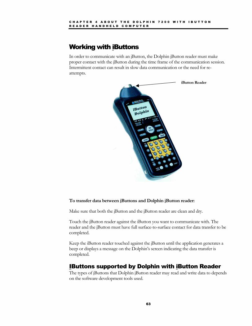
C H A P T E R 4 A B O U T T H E D O L P H I N 7 2 0 0 W I T H I B U T T O N R E A D E R H A N D H E L D C O M P U T E R
63
Working with iButtons In order to communicate with an iButton, the Dolphin iButton reader must make proper contact with the iButton during the time frame of the communication session. Intermittent contact can result in slow data communication or the need for re-attempts.
To transfer data between iButtons and Dolphin iButton reader:
Make sure that both the iButton and the iButton reader are clean and dry.
Touch the iButton reader against the iButton you want to communicate with. The reader and the iButton must have full surface-to-surface contact for data transfer to be completed.
Keep the iButton reader touched against the iButton until the application generates a beep or displays a message on the Dolphin’s screen indicating the data transfer is completed.
IButtons supported by Dolphin with iButton Reader The types of iButtons that Dolphin iButton reader may read and write data to depends on the software development tools used.
iButton Reader
C H A P T E R 4 A B O U T T H E D O L P H I N 7 2 0 0 W I T H I B U T T O N R E A D E R H A N D H E L D C O M P U T E R
64
Read/write iButton types that Dolphin iButton reader can read/write to include:
• DS 197X range EEPROM Devices
• DS 199X range NVRAM devices (with the exception of DS1990A, which is read only)
• DS 1954 Crypto iButton
• DS 1963 Monetary iButton
• DS 1921 Thermochron iButton
Compatible read-only iButton types that Dolphin iButton reader can read include:
• DS 1990A Serial number iButton
• DS 1920 Temperature iButton
Compatible read/write iButtons that the Dolphin iButton reader can read include:
• DS 198X EPROM devices
Developing Applications with Dolphin with iButton Reader Hand Held Products has a Software Developer’s Kit (SDK) that includes the following: 1. API for iButton functions that support the most commonly used iButton types
and concern file handling and data manipulation of iButton specific features. May be used in conjunction with Dolphin Development System.
2. Demo software and source code examples
Note: In addition, developers need the MicroSoft C/C++ or Borland C/C++ compiler.
65
Chapter 5 Dolphin® 7200 RS-232 Handheld Computer
C H A P T E R 5 D O L P H I N 7 2 0 0 R S - 2 3 2 H A N D H E L D C O M P U T E R
66
About Dolphin 7200 RS-232 Hand Held Computer The Dolphin® 7200 hand held computer with a Micro-DB9 RS-232 port is a compact, high performance data collection terminal with standard connectivity at a low cost. Capable of reading all popular linear barcodes, the Dolphin 7200 terminal fits into an array of environments.
Through the terminal’s micro-DB9 RS-232 port, the Dolphin 7200 can be connected to a host computer to send and receive data. The terminal’s battery can be recharged through the RS-232 port using the Dolphin 7200 communication/charging cable and a power adapter or the Dolphin HomeBase™ charging/communications cradle.
The Dolphin 7200 can connect to self-powered, RS-232-compliant peripherals, such as external modems and printers, GPS receivers, electronic scales, and various input devices via the micro-DB9 RS-232 port. Wireless IrDA connectivity remains available, allowing users to connect with IrDA-compliant printers through the IR port.
Dolphin 7200 Wand The Dolphin 7200 Wand is two-product package featuring a special configuration of the Dolphin 7200 RS-232 and a SCANTEAM 6180 bar code wand reader/decoder. The Dolphin 7200 RS-232 terminal featured in the wand package is a non-scan unit and has a special micro-DB-9 connector that provides power for the wand scanner. Therefore, the wand scanner will only work with this configuration of the Dolphin 7200 RS-232 terminal.
For programming/configuring the wand, refer to the SCANTEAM® 6180 Programming Menu and SCANTEAM Technical Menu.
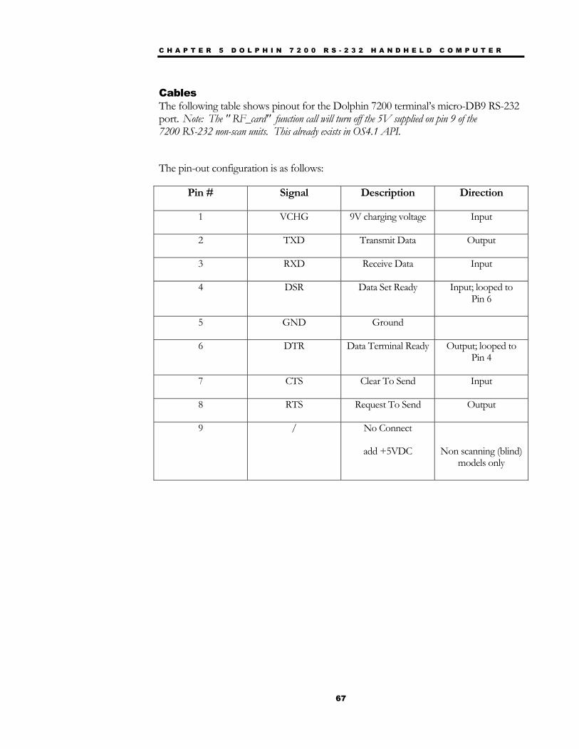
C H A P T E R 5 D O L P H I N 7 2 0 0 R S - 2 3 2 H A N D H E L D C O M P U T E R
67
Cables The following table shows pinout for the Dolphin 7200 terminal’s micro-DB9 RS-232 port. Note: The " RF_card" function call will turn off the 5V supplied on pin 9 of the 7200 RS-232 non-scan units. This already exists in OS4.1 API.
The pin-out configuration is as follows:
Pin # Signal Description Direction
1 VCHG 9V charging voltage Input
2 TXD Transmit Data Output
3 RXD Receive Data Input
4 DSR Data Set Ready Input; looped to Pin 6
5 GND Ground
6 DTR Data Terminal Ready Output; looped to Pin 4
7 CTS Clear To Send Input
8 RTS Request To Send Output
9 / No Connect
add +5VDC
Non scanning (blind) models only
C H A P T E R 5 D O L P H I N 7 2 0 0 R S - 2 3 2 H A N D H E L D C O M P U T E R
68
Charging The Battery Through The RS-232 Port Before initial use, the Dolphin 7200 RS-232 terminal should be charged for 24 hours. Follow these steps to charge the Dolphin 7200 RS-232 terminal using the RS-232 port:
1. Plug the adapter into electrical outlet.
2. Insert a battery pack into the battery well of the terminal.
3. Insert the micro-DB-9 RS-232 connector on the communication/charging cable into the micro-DB-9 port on the back of the Dolphin 7200 RS-232 terminal.
4. Connect the Universal Power Charging Adapter (Part #PS9U-11) into the adapter end of the communication/charging cable. Note: The charging adapter is a regulated 9V power supply and, due to the different connector, cannot be used with the HomeBase.
For more on maintaining the batteries, see the section on Maintaining Batteries in Chapter 2.
Sending and Receiving Data The Dolphin 7200 RS-232 terminal can be connected to a host computer to send and receive data via the micro-DB9 RS-232 port using the YX.EXE Utility or the Dolphin File Transfer Program.
Follow these steps to set up the terminal for sending and receiving data:
1. Insert a battery pack into the battery well of the terminal.
2. Insert the micro-DB-9 RS-232 connector to the Dolphin communication (only) cable into the micro-DB-9 port on the back of the Dolphin 7200 RS-232 terminal.
3. Connect the DB-9 connector to your PC’s serial port.
4. Run the YX.EXE utility or the Dolphin File Transfer Program.
For more on sending and receiving data using YX.EXE and the Dolphin File Transfer Program, see the section on Transferring Files to or From Dolphin in Chapter 9.
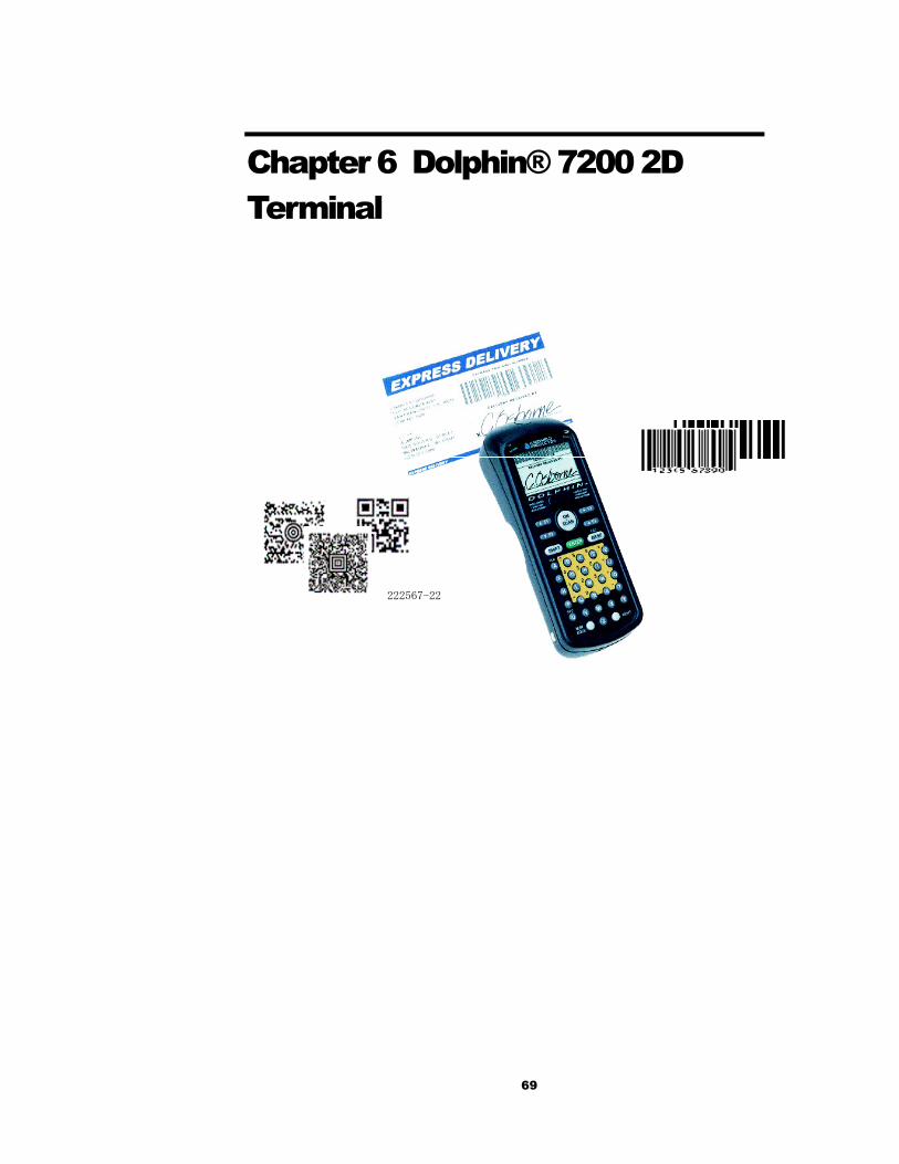
69
Chapter 6 Dolphin® 7200 2D Terminal
222567-22

C H A P T E R 6 D O L P H I N 7 2 0 0 2 D H A N D H E L D C O M P U T E R
70
About the Dolphin 7200 2D Hand Held Computer The Dolphin® 7200 2D hand held computer features the IMAGETEAM ™ 4250 Image Engine, a low power, high-resolution digital image engine for omni-directional and auto-discrimination reading and decoding of linear barcodes, stacked linear (PDF417) and 2D matrix codes. The image engine functions like a digital camera and also provides OCR (Optical Character Recognition) functionality.
The terminal is available in several configurations with alphanumeric and numeric keyboard options. These configurations include the standard range (LR), long range (LX), and high-density (HD) engines with 2MB RAM and 8MB non-volatile FLASH memory.
The 2D terminal has image lift capabilities for signature capture and proof of delivery applications. Images taken with the unit can be compressed and stored using industry-standard data compression technologies. The device provides the flexibility to store either images that contain grayscale information or black and white only information. Images can be downloaded via HomeBase™ or VehicleBase™ communication cradles and then transmitted via one of many wired or wireless options.
The terminal is also able to decode barcode symbologies and capture images in dim lighting conditions or complete darkness.
Supported Symbologies 1D linear codes: Code 3 of 9, Interleaved 2 of 5, TLC Code 39, Code 11, MSI, UPC A, UPC EO, UPC EI, EAN/EAN13, Codabar, Code 128, Code 93, UPC 2D codes: PDF417, microPDF, Maxicode, Datamatrix, Aztec, QR Code, Code 49 Composite codes: RSS-14, CODABLOCK, AZTEC MESA OCR codes (Optical Character Recognition): OCR A and OCR B Postal Codes: Postnet and most international 4 state codes, PLANET CODE, BPO 4 STATE, CANADIAN 4 STATE, DUTCH POSTAL, AUSTRALIAN 4 STATE, JAPANESE POSTAL For other supported symbologies, please see the IMAGETEAM ™ 4250 User’s Guide.
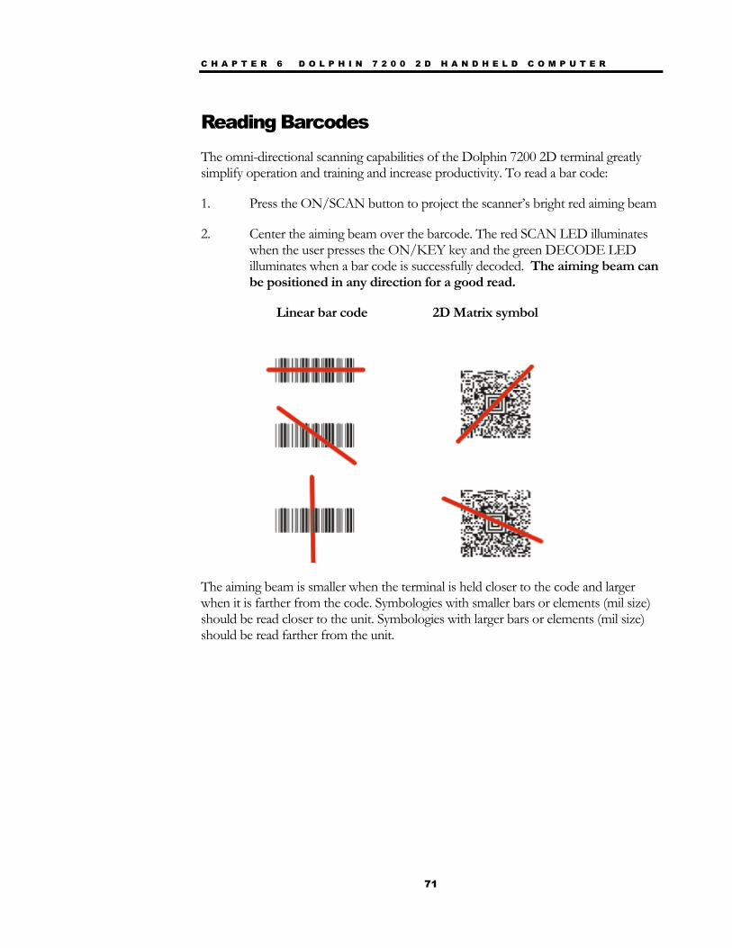
C H A P T E R 6 D O L P H I N 7 2 0 0 2 D H A N D H E L D C O M P U T E R
71
Reading Barcodes The omni-directional scanning capabilities of the Dolphin 7200 2D terminal greatly simplify operation and training and increase productivity. To read a bar code:
1. Press the ON/SCAN button to project the scanner’s bright red aiming beam
2. Center the aiming beam over the barcode. The red SCAN LED illuminates when the user presses the ON/KEY key and the green DECODE LED illuminates when a bar code is successfully decoded. The aiming beam can be positioned in any direction for a good read.
Linear bar code 2D Matrix symbol
The aiming beam is smaller when the terminal is held closer to the code and larger when it is farther from the code. Symbologies with smaller bars or elements (mil size) should be read closer to the unit. Symbologies with larger bars or elements (mil size) should be read farther from the unit.
C H A P T E R 6 D O L P H I N 7 2 0 0 2 D H A N D H E L D C O M P U T E R
72
Capturing Images
The image-capture process is a split-second operation for experienced users. By following the basic guidelines, new users can easily develop their own technique and, with practice, quickly learn to adapt it to different circumstances. The basic steps for acquiring images using the Dolphin 7200 2D terminal are:
1. To aim, hold the Dolphin terminal horizontally at a 45° angle approximately 2 to 9
inches (5 to 20 cm) away from the target. You may have to adjust the angle at which you hold the Dolphin if there is glare on the screen.
2. Press the ON/SCAN button to take an image. Use the live video image on the terminal screen as a guide for positioning and aiming the terminal at the target. You may find it helpful to start by moving the terminal further away and then in closer to the target. The active screen image will have a slightly degraded appearance compared to the captured image. This is normal.
3. Release the ON/SCAN button to capture the image when the desired image is displayed on the terminal screen. Hold the Dolphin terminal as still as possible when capturing the image.
The image quality and related file size is determined by the data compression method used by your software application. For highest quality, take grayscale images. When saved, the image will be saved in JPEG file format. The size of the file depends on the information content of the image and will be approximately 4-8 K.
Lighting Conditions The Dolphin 7200 2D terminal is designed to read bar codes and take images in dim light conditions. It is suggested that you turn on the unit’s electroluminescent display backlight when taking images in extreme low light conditions to help with aiming.

C H A P T E R 6 D O L P H I N 7 2 0 0 2 D H A N D H E L D C O M P U T E R
73
Dolphin 7200 2D Demo Software The Dolphin 7200 2D terminal demonstration software allows you to show terminal’s ability to do omni-directional decoding, image capture and I.Q. Imaging.
The Image Capture demo requires that you have a PC available with a program such as the Dolphin File Transfer utility that is capable of receiving files via Ymodem protocol, and a Dolphin home base connected to that PC.
For more information on using the Dolphin File Transfer Utility, see the section on Transferring Files To or From Dolphin in Chapter 9.
Installing the Dolphin 7200 Demo Applications The Dolphin 7200 2D terminal is shipped loaded with the demonstration software.
If the demo software has been removed from your terminal, follow these steps to re-install it:
1. Download the demonstration installation programs from the HHP website. www.handheld.com. The program is called DEMOS.EXE.
2. Use the Dolphin File Transfer utility to load DEMOS.EXE onto the Dolphin unit.
3. Run DEMOS.EXE once the program is loaded onto the Dolphin. It is a self-extracting Zip file that installs the demonstration applications. It will also offer to replace the Dolphin terminal’s AUTOEXEC.BAT file.
4. Start the demo program by typing DEMOSTART at the C:> prompt and then pressing <ENTER>. If you chose to let DEMOS.EXE overwrite the AUTOEXEC.BAT, perform a three-key reset (pressing and releasing the “SHIFT”, “ON/SCAN” and “BKSP” keys at the same time.) and the program will start.
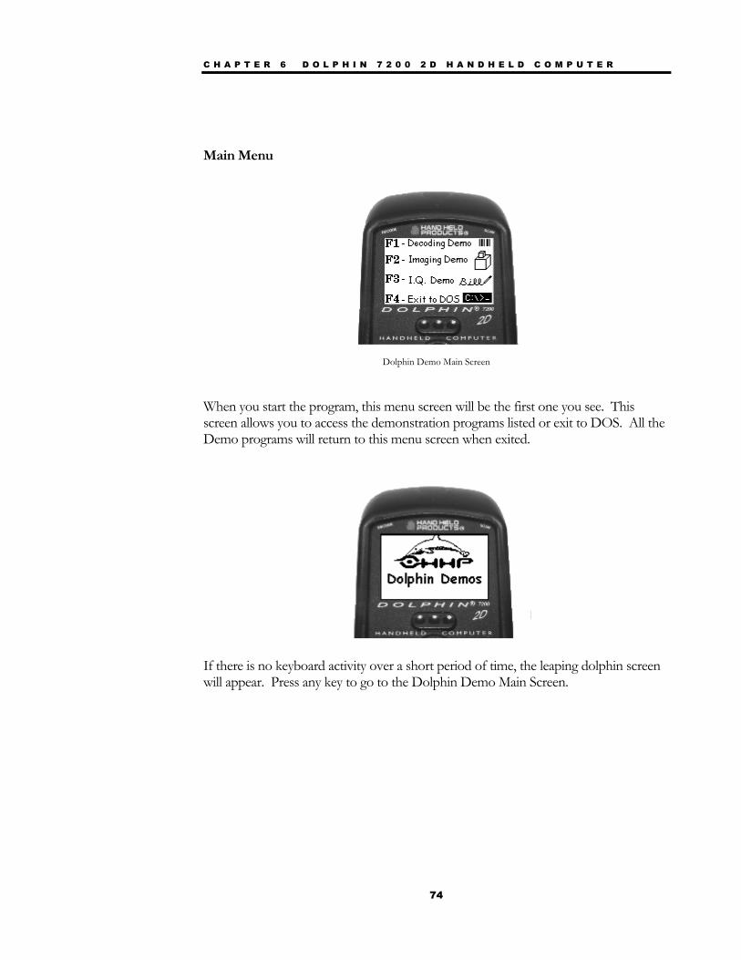
C H A P T E R 6 D O L P H I N 7 2 0 0 2 D H A N D H E L D C O M P U T E R
74
Main Menu
Dolphin Demo Main Screen
When you start the program, this menu screen will be the first one you see. This screen allows you to access the demonstration programs listed or exit to DOS. All the Demo programs will return to this menu screen when exited.
If there is no keyboard activity over a short period of time, the leaping dolphin screen will appear. Press any key to go to the Dolphin Demo Main Screen.
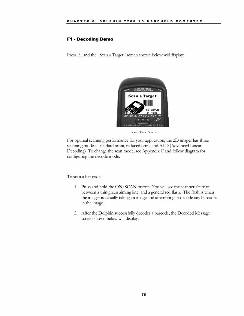
C H A P T E R 6 D O L P H I N 7 2 0 0 2 D H A N D H E L D C O M P U T E R
75
F1 - Decoding Demo
Press F1 and the “Scan a Target” screen shown below will display:
Scan a Target Screen
For optimal scanning performance for your application, the 2D imager has three scanning modes: standard omni, reduced omni and ALD (Advanced Linear Decoding) To change the scan mode, see Appendix C and follow diagram for configuring the decode mode.
To scan a bar code:
1. Press and hold the ON/SCAN button. You will see the scanner alternate between a thin green aiming line, and a general red flash. The flash is when the imager is actually taking an image and attempting to decode any barcodes in the image.
2. After the Dolphin successfully decodes a barcode, the Decoded Message screen shown below will display.
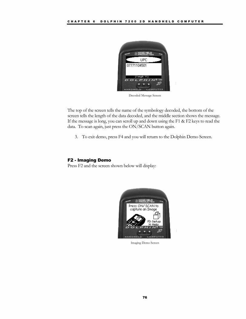
C H A P T E R 6 D O L P H I N 7 2 0 0 2 D H A N D H E L D C O M P U T E R
76
Decoded Message Screen
The top of the screen tells the name of the symbology decoded, the bottom of the screen tells the length of the data decoded, and the middle section shows the message. If the message is long, you can scroll up and down using the F1 & F2 keys to read the data. To scan again, just press the ON/SCAN button again.
3. To exit demo, press F4 and you will return to the Dolphin Demo Screen.
F2 - Imaging Demo Press F2 and the screen shown below will display:
Imaging Demo Screen
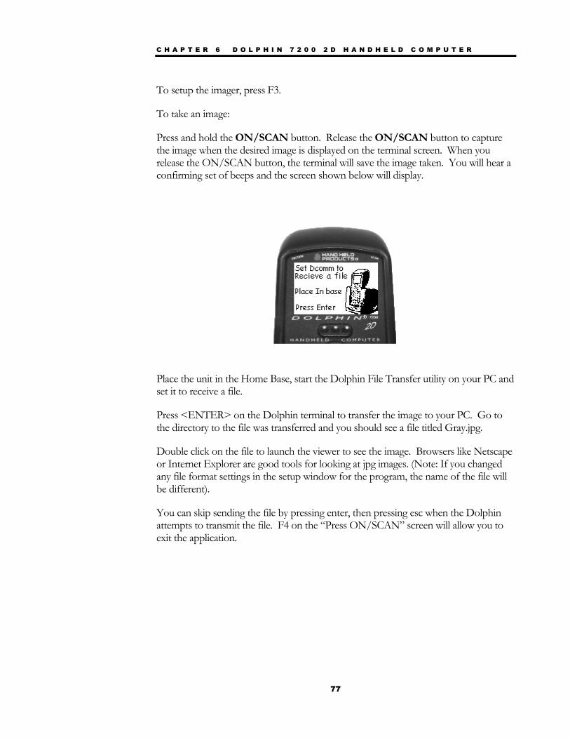
C H A P T E R 6 D O L P H I N 7 2 0 0 2 D H A N D H E L D C O M P U T E R
77
To setup the imager, press F3.
To take an image:
Press and hold the ON/SCAN button. Release the ON/SCAN button to capture the image when the desired image is displayed on the terminal screen. When you release the ON/SCAN button, the terminal will save the image taken. You will hear a confirming set of beeps and the screen shown below will display.
Place the unit in the Home Base, start the Dolphin File Transfer utility on your PC and set it to receive a file.
Press <ENTER> on the Dolphin terminal to transfer the image to your PC. Go to the directory to the file was transferred and you should see a file titled Gray.jpg.
Double click on the file to launch the viewer to see the image. Browsers like Netscape or Internet Explorer are good tools for looking at jpg images. (Note: If you changed any file format settings in the setup window for the program, the name of the file will be different).
You can skip sending the file by pressing enter, then pressing esc when the Dolphin attempts to transmit the file. F4 on the “Press ON/SCAN” screen will allow you to exit the application.
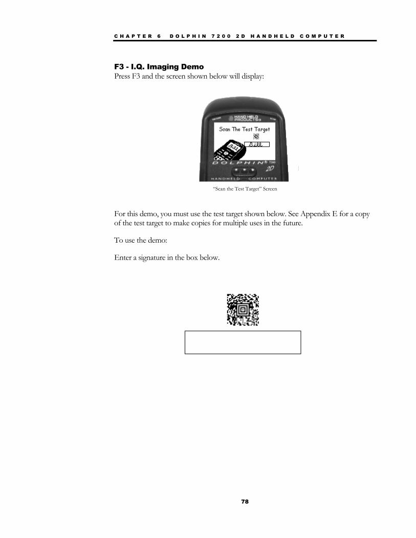
C H A P T E R 6 D O L P H I N 7 2 0 0 2 D H A N D H E L D C O M P U T E R
78
F3 - I.Q. Imaging Demo Press F3 and the screen shown below will display:
“Scan the Test Target” Screen
For this demo, you must use the test target shown below. See Appendix E for a copy of the test target to make copies for multiple uses in the future.
To use the demo:
Enter a signature in the box below.
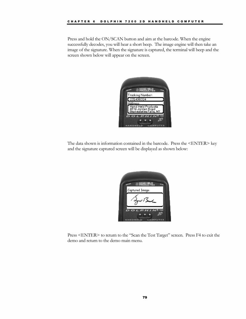
C H A P T E R 6 D O L P H I N 7 2 0 0 2 D H A N D H E L D C O M P U T E R
79
Press and hold the ON/SCAN button and aim at the barcode. When the engine successfully decodes, you will hear a short beep. The image engine will then take an image of the signature. When the signature is captured, the terminal will beep and the screen shown below will appear on the screen.
The data shown is information contained in the barcode. Press the <ENTER> key and the signature captured screen will be displayed as shown below:
Press <ENTER> to return to the “Scan the Test Target” screen. Press F4 to exit the demo and return to the demo main menu.

80
Chapter 7 Using the Dolphin® 7200 HomeBase Summarizes the features of the Dolphin 7200 HomeBase and explains how to use it.
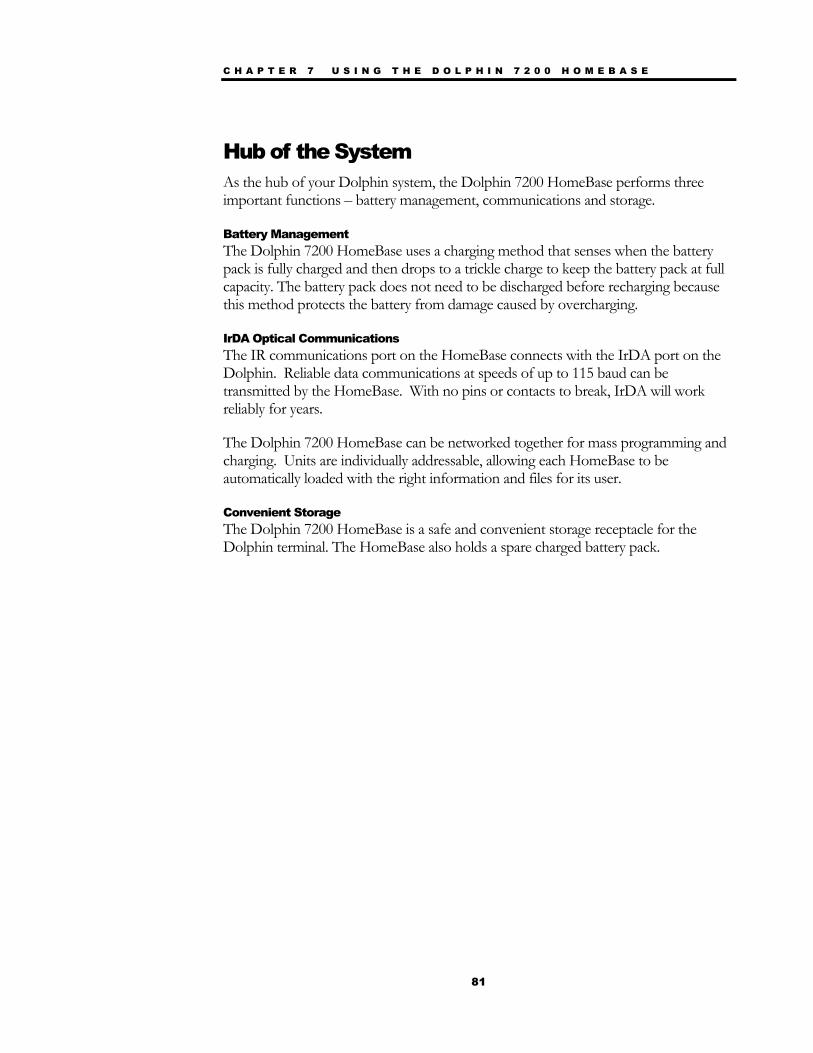
C H A P T E R 7 U S I N G T H E D O L P H I N 7 2 0 0 H O M E B A S E
81
Hub of the System As the hub of your Dolphin system, the Dolphin 7200 HomeBase performs three important functions – battery management, communications and storage.
Battery Management The Dolphin 7200 HomeBase uses a charging method that senses when the battery pack is fully charged and then drops to a trickle charge to keep the battery pack at full capacity. The battery pack does not need to be discharged before recharging because this method protects the battery from damage caused by overcharging.
IrDA Optical Communications The IR communications port on the HomeBase connects with the IrDA port on the Dolphin. Reliable data communications at speeds of up to 115 baud can be transmitted by the HomeBase. With no pins or contacts to break, IrDA will work reliably for years.
The Dolphin 7200 HomeBase can be networked together for mass programming and charging. Units are individually addressable, allowing each HomeBase to be automatically loaded with the right information and files for its user.
Convenient Storage The Dolphin 7200 HomeBase is a safe and convenient storage receptacle for the Dolphin terminal. The HomeBase also holds a spare charged battery pack.
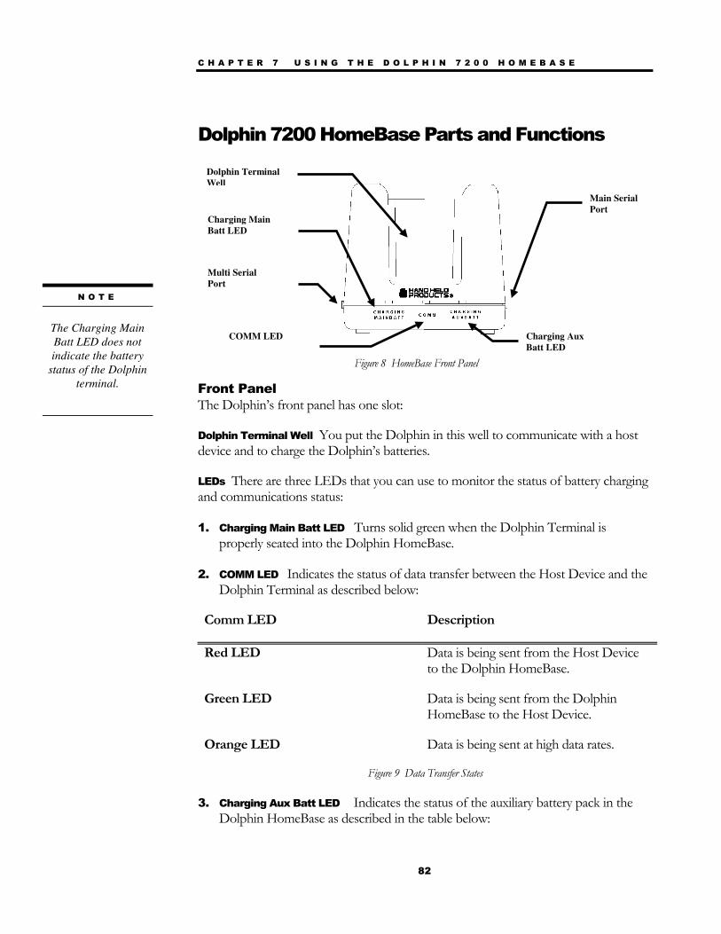
C H A P T E R 7 U S I N G T H E D O L P H I N 7 2 0 0 H O M E B A S E
82
Dolphin 7200 HomeBase Parts and Functions
Front Panel The Dolphin’s front panel has one slot:
Dolphin Terminal Well You put the Dolphin in this well to communicate with a host device and to charge the Dolphin’s batteries.
LEDs There are three LEDs that you can use to monitor the status of battery charging and communications status:
1. Charging Main Batt LED Turns solid green when the Dolphin Terminal is properly seated into the Dolphin HomeBase.
2. COMM LED Indicates the status of data transfer between the Host Device and the Dolphin Terminal as described below:
Comm LED Description
Red LED Data is being sent from the Host Device to the Dolphin HomeBase.
Green LED Data is being sent from the Dolphin HomeBase to the Host Device.
Orange LED Data is being sent at high data rates.
Figure 9 Data Transfer States
3. Charging Aux Batt LED Indicates the status of the auxiliary battery pack in the Dolphin HomeBase as described in the table below:
N O T E
The Charging Main Batt LED does not indicate the battery
status of the Dolphin terminal.
Dolphin Terminal Well
Main Serial Port
Charging Main Batt LED
COMM LED Charging Aux Batt LED
Figure 8 HomeBase Front Panel
Multi Serial Port
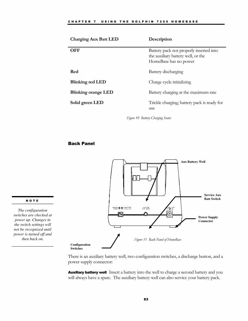
C H A P T E R 7 U S I N G T H E D O L P H I N 7 2 0 0 H O M E B A S E
83
Charging Aux Batt LED Description
OFF Battery pack not properly inserted into the auxiliary battery well, or the HomeBase has no power
Red Battery discharging
Blinking red LED Charge cycle initializing
Blinking orange LED Battery charging at the maximum rate
Solid green LED Trickle charging; battery pack is ready for use
Figure 10 Battery Charging States
Back Panel
There is an auxiliary battery well, two configuration switches, a discharge button, and a power supply connector:
Auxiliary battery well Insert a battery into the well to charge a second battery and you will always have a spare. The auxiliary battery well can also service your battery pack.
Aux Battery Well
Configuration Switches
Service Aux Batt Switch
Power Supply Connector
Figure 11 Back Panel of HomeBase
N O T E
The configuration
switches are checked at power up. Changes in the switch settings will not be recognized until power is turned off and
then back on.
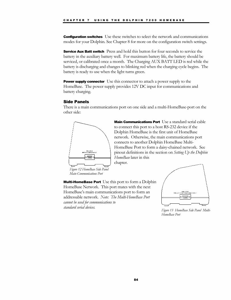
C H A P T E R 7 U S I N G T H E D O L P H I N 7 2 0 0 H O M E B A S E
84
Configuration switches Use these switches to select the network and communications modes for your Dolphin. See Chapter 8 for more on the configuration switch settings.
Service Aux Batt switch Press and hold this button for four seconds to service the battery in the auxiliary battery well. For maximum battery life, the battery should be serviced, or calibrated once a month. The Charging AUX BATT LED is red while the battery is discharging and changes to blinking red when the charging cycle begins. The battery is ready to use when the light turns green.
Power supply connector Use this connector to attach a power supply to the HomeBase. The power supply provides 12V DC input for communications and battery charging.
Side Panels There is a main communications port on one side and a multi-HomeBase-port on the other side:
Main Communications Port Use a standard serial cable to connect this port to a host RS-232 device if the Dolphin HomeBase is the first unit of HomeBase network. Otherwise, the main communications port connects to another Dolphin HomeBase Multi-HomeBase Port to form a daisy-chained network. See pinout definitions in the section on Setting Up the Dolphin HomeBase later in this chapter.
Multi-HomeBase Port Use this port to form a Dolphin HomeBase Network. This port mates with the next HomeBase’s main communications port to form an addressable network. Note: The Multi-HomeBase Port cannot be used for communications to standard serial devices.
Figure 12 HomeBase Side Panel Main Communications Port
Figure 13 HomeBase Side Panel Multi-HomeBase Port
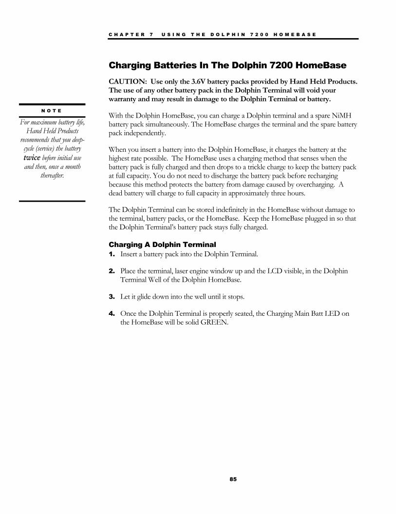
C H A P T E R 7 U S I N G T H E D O L P H I N 7 2 0 0 H O M E B A S E
85
Charging Batteries In The Dolphin 7200 HomeBase
CAUTION: Use only the 3.6V battery packs provided by Hand Held Products. The use of any other battery pack in the Dolphin Terminal will void your warranty and may result in damage to the Dolphin Terminal or battery.
With the Dolphin HomeBase, you can charge a Dolphin terminal and a spare NiMH battery pack simultaneously. The HomeBase charges the terminal and the spare battery pack independently.
When you insert a battery into the Dolphin HomeBase, it charges the battery at the highest rate possible. The HomeBase uses a charging method that senses when the battery pack is fully charged and then drops to a trickle charge to keep the battery pack at full capacity. You do not need to discharge the battery pack before recharging because this method protects the battery from damage caused by overcharging. A dead battery will charge to full capacity in approximately three hours.
The Dolphin Terminal can be stored indefinitely in the HomeBase without damage to the terminal, battery packs, or the HomeBase. Keep the HomeBase plugged in so that the Dolphin Terminal’s battery pack stays fully charged.
Charging A Dolphin Terminal 1. Insert a battery pack into the Dolphin Terminal.
2. Place the terminal, laser engine window up and the LCD visible, in the Dolphin Terminal Well of the Dolphin HomeBase.
3. Let it glide down into the well until it stops.
4. Once the Dolphin Terminal is properly seated, the Charging Main Batt LED on the HomeBase will be solid GREEN.
N O T E
For maximum battery life, Hand Held Products
recommends that you deep- cycle (service) the battery twice before initial use and then, once a month
thereafter.
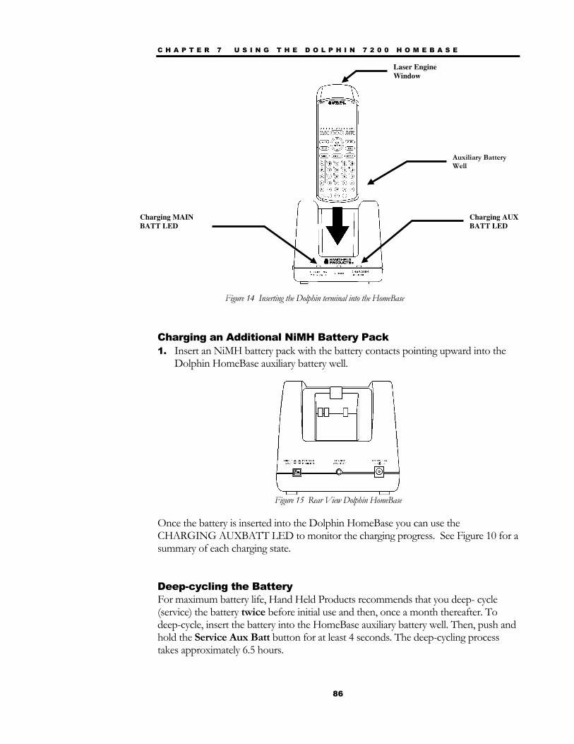
C H A P T E R 7 U S I N G T H E D O L P H I N 7 2 0 0 H O M E B A S E
86
Figure 14 Inserting the Dolphin terminal into the HomeBase
Charging an Additional NiMH Battery Pack 1. Insert an NiMH battery pack with the battery contacts pointing upward into the
Dolphin HomeBase auxiliary battery well.
Figure 15 Rear View Dolphin HomeBase
Once the battery is inserted into the Dolphin HomeBase you can use the CHARGING AUXBATT LED to monitor the charging progress. See Figure 10 for a summary of each charging state.
Deep-cycling the Battery For maximum battery life, Hand Held Products recommends that you deep- cycle (service) the battery twice before initial use and then, once a month thereafter. To deep-cycle, insert the battery into the HomeBase auxiliary battery well. Then, push and hold the Service Aux Batt button for at least 4 seconds. The deep-cycling process takes approximately 6.5 hours.
Charging MAIN BATT LED
Charging AUX BATT LED
Laser Engine Window
Auxiliary Battery Well
C H A P T E R 7 U S I N G T H E D O L P H I N 7 2 0 0 H O M E B A S E
87
The CHARGING AUXBATT LED is red while the battery is discharging and changes to blinking red when the charging cycle begins and orange when charging at the maximum rate. The battery is ready to use when the light turns green. See Figure 10 for more on the LED status.
Setting Up For Communications The Dolphin Terminal and Dolphin HomeBase support RS-232 communications through the RS-232 Main Communications Port located on the side of the Dolphin 7200 HomeBase. The HomeBase translates the RS-232 signals from the host computer into infrared signals to communicate with the Dolphin Terminal.
The HomeBase RS-232 interface allows the Dolphin Terminal to communicate to a personal computer, modem, or any standard RS-232 device using a standard serial cable and communications software.
Follow these steps to set up the Dolphin HomeBase and Dolphin Terminal for communications:
1. Set-up the Dolphin HomeBase.
2. Set-up the Dolphin Terminal.
3. Follow the data transfer sequence as described by your application.
Setting up the Dolphin HomeBase
Set the Dolphin HomeBase on any dry, stable surface such as a desktop. Before mounting the Dolphin HomeBase, check to ensure that all AC wall transformers have a nearby electrical outlet. Be sure to provide enough workspace with good lighting for the user to view and operate the Dolphin Terminal while it is in the HomeBase. Setting up the HomeBase involves three steps:
1. Connecting the cables
2. Setting the configuration switches
3. Setting the baud rate
Connecting the Cables Connect the HomeBase to the host computer or other device by plugging an RS-232 serial cable into the RS-232 Communications Port on the rear of the HomeBase. The

C H A P T E R 7 U S I N G T H E D O L P H I N 7 2 0 0 H O M E B A S E
88
wiring of your cable depends on whether the other device is set up as a DCE (Data Communications Equipment) or DTE (Data Terminal Equipment) device.
The HomeBase RS-232 Port is configured as a DCE device. To communicate with a DTE device such as a computer, use a standard (or straight-through) RS-232 cable. To communicate with a DCE device, use either a null modem adapter in line with a standard RS-232 cable, or a null-modem serial cable.
You can make your own cables by following the pin configuration in the chart below. To do so, you must determine if your host RS-232 device is 9-pin or 25-pin, and whether it is configured as a DCE or DTE device.
HomeBase /Host Port
(DCE)
IBM AT DB9 (DTE)
IBM XT DB25 (DTE)
Modem DB25 (DCE)
2 (RD) 2 3 2
3 (TD) 3 2 3
5 (SG) 5 7 7
4 (DTR) 4 20 6
6 (DSR) 6 6 20
7 (RTS) 7 4 5
8 (CTS) 8 5 4
Figure 16 Pin Configuration
With the Dolphin 7200 HomeBase, use the appropriate cable to connect each device to the Main Comm Port for a single Dolphin HomeBase or to the Multi-HomeBase Port if you are creating a Dolphin HomeBase network.
Connect the power supply to the Dolphin HomeBase. Plug the AC transformer into the Dolphin HomeBase 12 Volt DC power supply connector. The AC wall transformer provided can power only one Dolphin HomeBase.
Hand Held Products recommends that you leave the Dolphin HomeBase connected to its power source at all times, so that it is always ready to use.
Setting the Configuration Switches Use these switches to select the network and communications modes for your Dolphin HomeBase. If you are configuring the HomeBase for a single Dolphin Terminal, the switch must be in the ‘Single’ position for proper basic operation. The switch must be set to ‘Multi’ for proper network operation if you are creating a HomeBase network. The configuration switch must be in the program position to change the baud rate.
C H A P T E R 7 U S I N G T H E D O L P H I N 7 2 0 0 H O M E B A S E
89
Setting the Baud Rate You may use the HomeBase Configuration utility program to select the baud rate. The program can also be used to change the host system’s COM port and will run a diagnostic check for optimal communications. After changing the baud rate, you must power the HomeBase off and then on again. The program is one of the utility programs that come with the Dolphin OS and Development System. For more on HomeBase Configuration, see the chapter 9.
Modes of Operation Through the Command Mode, the host application software provides command instructions for configuring a single Dolphin HomeBase or a network of HomeBases for communications. Once configured, the HomeBase(s) is in Transparent Mode and ready for communications.
Command Mode You can configure a single Dolphin HomeBase or a whole network and select units for communications via the host application by entering the Command Mode. Data transmission is not possible while the Dolphin HomeBase network is in this mode. Go into Command Mode by entering an escape sequence that informs the HomeBase network that it will be receiving commands from the host device or application. The escape string is:
<ESC>HHP [>100ms<1s] Next Command
where <ESC> is an ASCII 27 character. The escape string should be followed by a >100ms<1second period of line silence. When sending commands, the escape string must precede the command string. The HomeBase automatically exits Command Mode after receiving each command.
Programming commands used for configuring single Dolphin HomeBases include Version Number and Baud Rate Selection. You configure HomeBase networks using the Baud Rate Selection, Address Assignment and Device Selection programming commands. See the sections on Configuring A Single Dolphin HomeBase and Creating a HomeBase Network for details.
Transparent Mode When the Dolphin HomeBase is selected by the host application and ready for communications, it is in Transparent Mode. In this mode, the HomeBase facilitates point-to-point communication between the host device and the Dolphin Terminal. Data sent through the RS-232 link is passed directly to and from the Dolphin Terminal via the Infrared Link between the terminal and the HomeBase.
C H A P T E R 7 U S I N G T H E D O L P H I N 7 2 0 0 H O M E B A S E
90
Configuring a Single Dolphin 7200 HomeBase
To prepare a single Dolphin HomeBase for communications, you must enter the Command Mode to configure the version number and select the baud rate.
Version Number To retrieve the version number for the Dolphin HomeBase:
1. Enter or send the escape and command strings: <ESC>HHP >100ms< 1s V
This command will return the version number but is not needed for communications.
Baud Rate Selection The Dolphin HomeBase baud rate is set to 57600 at the factory. Use the configuration switches on the HomeBase’s back panel to select the network and communications modes for your Dolphin. The following table outlines the configuration switch settings:
Switch Setting Function
1 SINGLE (UP) Single HomeBase only
2 FIXED BPS (DOWN)
Baud rate fixed at 9600
2 PROGRAM (UP) Baud rate can be programmed
Figure 17 Configuration Switch Settings on HomeBase for Single HomeBase
To ensure communications, leave Switch 2 in the ‘FIXED BPS’ position and configure your communications software for 9600 baud. When Switch 2 is in the ‘PROGRAM’ position, the baud rate can be changed using the following procedure or you may use the HomeBase Configuration Utility program.
1. Enter or send the escape and command strings:
<ESC>HHP >100ms< 1s Bn
where n is the ASCII number corresponding to the baud rate shown in the table below. For example, the string <ESC>HHPB6 (which consists of the escape string and the command B6) would set the baud rate for the network to 19200. No response will be transmitted back to the host after executing this function.
N O T E
The baud rate is stored
in Non-Volatile Memory and is retained even if the power is removed
from the network.
N O T E
The configuration
switches are checked at power up. Changes in the switch settings will not be recognized until power is
turned off and then back on.
C H A P T E R 7 U S I N G T H E D O L P H I N 7 2 0 0 H O M E B A S E
91
ASCII Value of “n”
Selected Baud Rate
ASCII Value of “n”
Selected Baud Rate
0 38400 6 19200 1 38400 7 38400 2 1200 8 57600 3 2400 9 115200 5 9600
Figure 18 Baud Rate per Value of n
Creating a Dolphin 7200 HomeBase Network
This information applies only to the Dolphin 7200 HomeBase. The Dolphin 7200 Compact HomeBase is not networkable. Each HomeBase must have its own AC power adapter connected to a standard AC electrical socket. The group can be placed on a table or desk, or rail-mounted using the mounting holes on the two outside Dolphin HomeBase units.
How to Daisy Chain the Dolphin HomeBases To form a HomeBase network, daisy chain the HomeBases together using one of the following methods:
• Align adjacent units so that the MULTI-HOMEBASE PORT of one unit will mate with the MAIN COMM PORT of the next unit until all HomeBases in the network are connected.
OR
• Use a RS-232 cable to connect the Multi-HomeBase Port on one terminal to the MAIN COMM PORT on the next terminal. Repeat this step to include each additional terminal in the chain. Connect the last terminal to the host computer and leave the last MULTI-HOMEBASE PORT open if it is not needed.
Programming Commands To configure a Dolphin HomeBase network, these attributes must be programmed: Address Assignment, Baud Rate Selection and Device Selection.
Address Assignment Use the Address Assignment command to establish unit IDs for each Dolphin HomeBase in your network. This must be done before a unit can be selected for communications. To establish an Address Assignment:
C H A P T E R 7 U S I N G T H E D O L P H I N 7 2 0 0 H O M E B A S E
92
1. Type or send the escape and command strings to set-up the configuration mode and establish the beginning unit ID number:
<ESC>HHP >100 ms< C >100 ms< 1s In
n is the number representing the first unit in the network
For example, the string <ESC>HHPCI0 would instruct the network to set up ID numbers for all the units in the network beginning at zero (0).
2. The first Dolphin HomeBase in the network receiving the command responds to the host with:
<SYN>
<SYN> indicates that the command was accepted
3. In sequence, each Dolphin HomeBase will determine its own ID number by adding one to the previous ID number.
4. When ID numbers are established for all HomeBases, the last HomeBase will return this response to the host:
<ACK>n
<ACK> indicates completion of ID configuration; n represents the ID number for the last unit in the network.
Programmer’s Note: When sending ID numbers to the Dolphin HomeBase, remember that numbers typed on the keyboard are ASCII numbers which will be converted to Hex when sent to the Dolphin HomeBase. For example, typing the command from the keyboard: <ESC>HHP >100ms< C >100ms< 1s I1
would instruct the network to set up ID numbers for each Dolphin HomeBase starting with the ASCII number 1. The first unit in the network would actually receive the number 31 Hex (since ASCII 1 is equal to 31 Hex) as the starting ID number. Each unit in the network would sequentially add one to this starting ID number to establish its own ID. So, for a network of 15 units, the final ID number would be set up as 3F Hex. When the final unit sends back an <ACK>3F, the host computer (which converts Hex data back to ASCII) will then display the ID number as “?” instead of 15 as you might expect. Baud Rate Selection The Dolphin HomeBase baud rate is preset to 57600 at the factory. Use the configuration switches on the back panel of the HomeBase to select the network and communications modes for your Dolphin. The following table outlines the configuration switch settings:
N O T E
The configuration
switches are checked at power up. Changes in the switch settings will not be recognized until power is
turned off and back on.
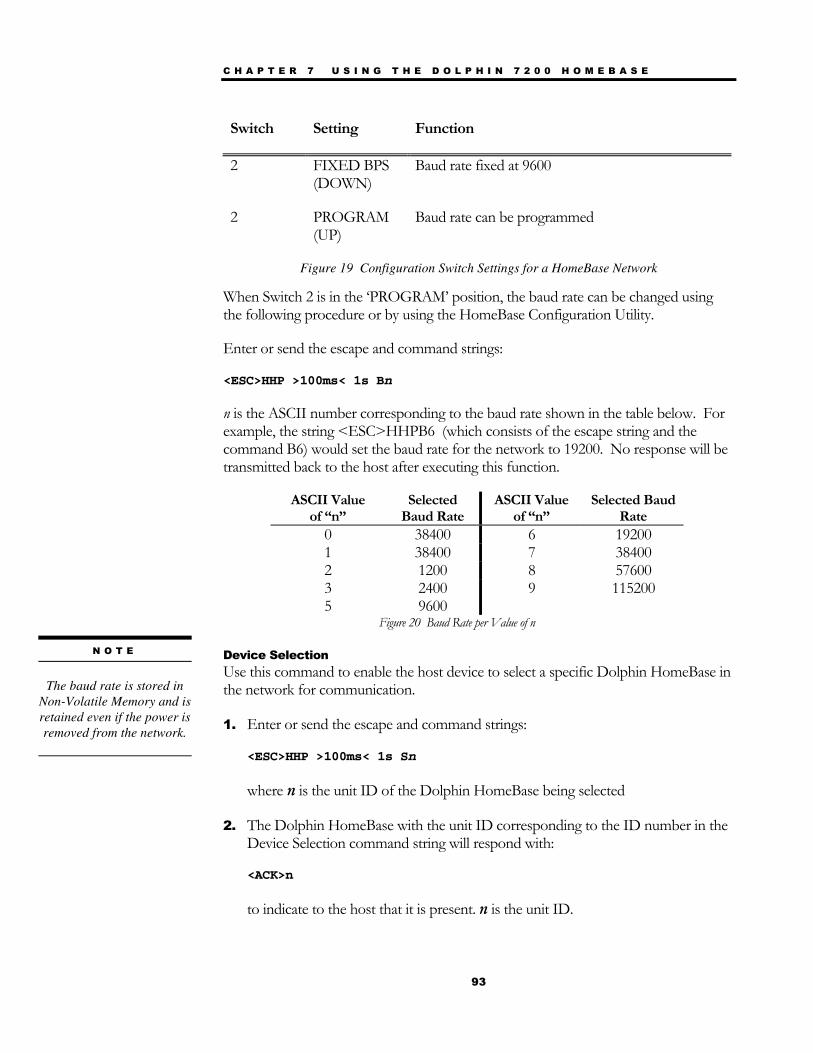
C H A P T E R 7 U S I N G T H E D O L P H I N 7 2 0 0 H O M E B A S E
93
Switch Setting Function
2 FIXED BPS (DOWN)
Baud rate fixed at 9600
2 PROGRAM (UP)
Baud rate can be programmed
Figure 19 Configuration Switch Settings for a HomeBase Network
When Switch 2 is in the ‘PROGRAM’ position, the baud rate can be changed using the following procedure or by using the HomeBase Configuration Utility.
Enter or send the escape and command strings:
<ESC>HHP >100ms< 1s Bn
n is the ASCII number corresponding to the baud rate shown in the table below. For example, the string <ESC>HHPB6 (which consists of the escape string and the command B6) would set the baud rate for the network to 19200. No response will be transmitted back to the host after executing this function.
ASCII Value of “n”
Selected Baud Rate
ASCII Value of “n”
Selected Baud Rate
0 38400 6 19200 1 38400 7 38400 2 1200 8 57600 3 2400 9 115200 5 9600
Figure 20 Baud Rate per Value of n
Device Selection Use this command to enable the host device to select a specific Dolphin HomeBase in the network for communication.
1. Enter or send the escape and command strings:
<ESC>HHP >100ms< 1s Sn
where n is the unit ID of the Dolphin HomeBase being selected
2. The Dolphin HomeBase with the unit ID corresponding to the ID number in the Device Selection command string will respond with:
<ACK>n
to indicate to the host that it is present. n is the unit ID.
N O T E
The baud rate is stored in
Non-Volatile Memory and is retained even if the power is removed from the network.

C H A P T E R 7 U S I N G T H E D O L P H I N 7 2 0 0 H O M E B A S E
94
When data transfer begins, the COMM LED on the Dolphin HomeBase will blink red and green. A unit remains selected until another unit in the network is selected. For example, the string <ESC>HHPS3 would select the unit with ID number 3 for communications. That unit would then send back an <ACK>3.
A selected unit in the Dolphin HomeBase network will assert the DSR signal of the HomeBase when a Dolphin terminal is present. The DSR signal can be used by the host application to determine if a Dolphin terminal is present and selected.
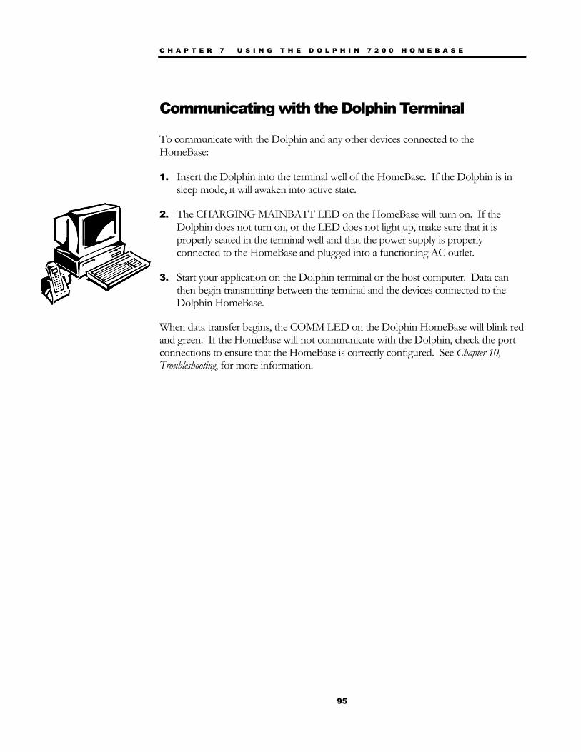
C H A P T E R 7 U S I N G T H E D O L P H I N 7 2 0 0 H O M E B A S E
95
Communicating with the Dolphin Terminal
To communicate with the Dolphin and any other devices connected to the HomeBase:
1. Insert the Dolphin into the terminal well of the HomeBase. If the Dolphin is in sleep mode, it will awaken into active state.
2. The CHARGING MAINBATT LED on the HomeBase will turn on. If the Dolphin does not turn on, or the LED does not light up, make sure that it is properly seated in the terminal well and that the power supply is properly connected to the HomeBase and plugged into a functioning AC outlet.
3. Start your application on the Dolphin terminal or the host computer. Data can then begin transmitting between the terminal and the devices connected to the Dolphin HomeBase.
When data transfer begins, the COMM LED on the Dolphin HomeBase will blink red and green. If the HomeBase will not communicate with the Dolphin, check the port connections to ensure that the HomeBase is correctly configured. See Chapter 10, Troubleshooting, for more information.

96
Chapter 8 Using the Dolphin® 7200 Compact HomeBase Summarizes the features of the Dolphin 7200 Compact HomeBase and explains how to use it.
C H A P T E R 8 U S I N G T H E D O L P H I N 7 2 0 0 C O M P A C T H O M E B A S E
97
Hub of the System As the hub of your Dolphin system, the Dolphin 7200 Compact HomeBase performs three important functions – battery management, communications and storage.
Battery Management The Dolphin 7200 Compact HomeBase uses a charging method that senses when the battery pack is fully charged and then drops to a trickle charge to keep the battery pack at full capacity. The battery pack does not need to be discharged before recharging because this method protects the battery from damage caused by overcharging.
The Dolphin 7200 Compact HomeBase provides power to the Dolphin terminal to enable the terminal to charge its battery.
IrDA Optical Communications The IR communications port on the Compact HomeBase connects with the IrDA port on the Dolphin. Reliable data communications at speeds of up to 115 baud can be transmitted by the HomeBase. With no pins or contacts to break, IrDA will work reliably for years.
The Dolphin 7200 Compact HomeBase is not networkable.
Convenient Storage The Dolphin 7200 Compact HomeBase is a safe and convenient storage receptacle for the Dolphin terminal.

C H A P T E R 8 U S I N G T H E D O L P H I N 7 2 0 0 C O M P A C T H O M E B A S E
98
Figure 16 Front View of HomeBase
Dolphin 7200 Compact HomeBase Parts and Functions Front Panel
The Compact HomeBase’s front panel has one slot:
Dolphin Terminal Well You put the Dolphin in this well to communicate with a host device and to charge the Dolphin’s batteries.
LEDs There are two LEDs on the front panel of the HomeBase
1. DOCK LED Turns solid green when the Dolphin Terminal is properly seated into the Dolphin HomeBase.
2. COMM LED Indicates the status of data transfer between the Host Device and the Dolphin Terminal as described below:
Comm LED Description
Red LED Data is being sent from the Host Device to the Dolphin HomeBase.
Green LED Data is being sent from the Dolphin HomeBase to the Host Device.
Orange LED Data is being sent at high data rates.
DOCK LED
COMM LED
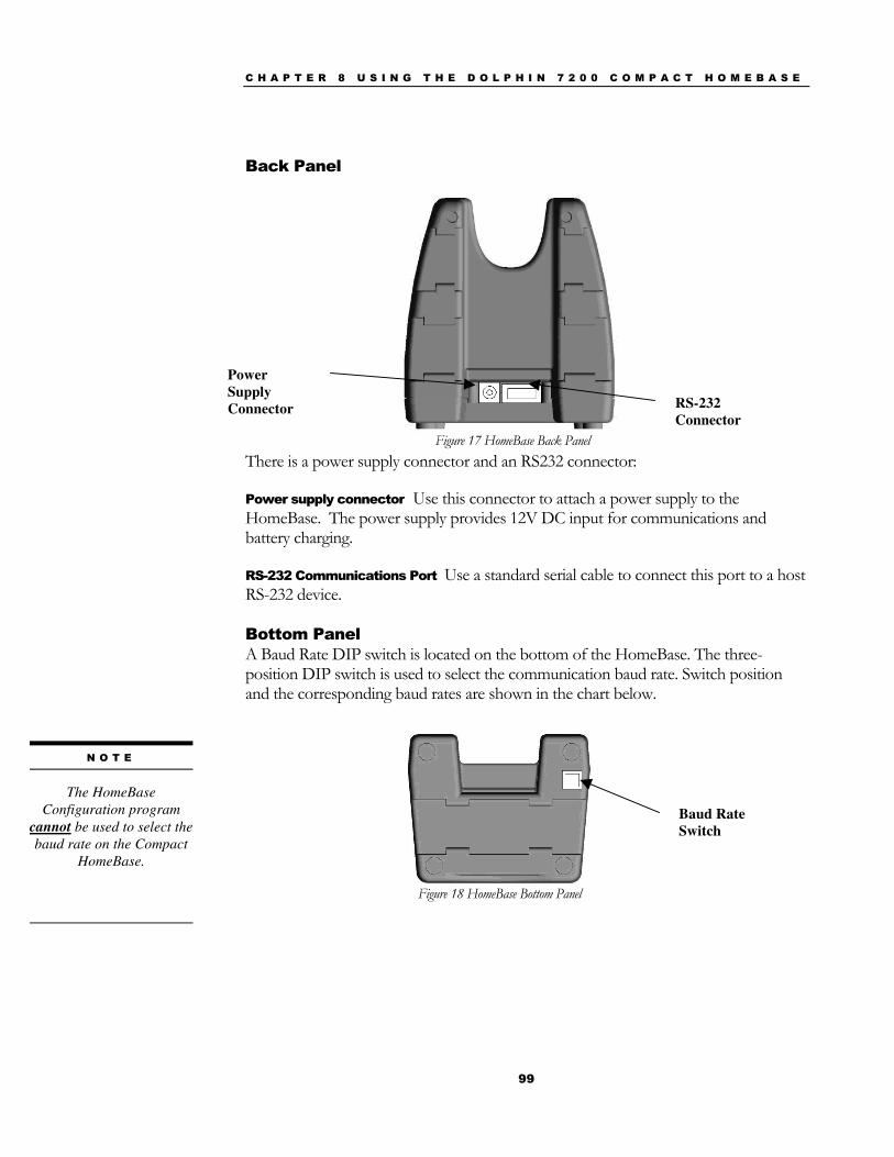
C H A P T E R 8 U S I N G T H E D O L P H I N 7 2 0 0 C O M P A C T H O M E B A S E
99
Back Panel
There is a power supply connector and an RS232 connector:
Power supply connector Use this connector to attach a power supply to the HomeBase. The power supply provides 12V DC input for communications and battery charging.
RS-232 Communications Port Use a standard serial cable to connect this port to a host RS-232 device.
Bottom Panel A Baud Rate DIP switch is located on the bottom of the HomeBase. The three-position DIP switch is used to select the communication baud rate. Switch position and the corresponding baud rates are shown in the chart below.
Figure 17 HomeBase Back Panel
Figure 18 HomeBase Bottom Panel
Baud Rate Switch
Power Supply Connector RS-232
Connector
N O T E
The HomeBase
Configuration program cannot be used to select the baud rate on the Compact
HomeBase.

C H A P T E R 8 U S I N G T H E D O L P H I N 7 2 0 0 C O M P A C T H O M E B A S E
100
Baud Rate Switch 1 Switch 2 Switch 3
115200 0 0 0
57600 1 0 0
19200 0 1 0
9600 1 1 0
38400 0 0 1
4800 1 0 1
2400 0 1 1
Note: The HomeBase Configuration program cannot be used to select the baud rate on the Compact HomeBase.
Powering the Dolphin Terminal When seated in the HomeBase, the Dolphin terminal receives the power it needs to charge the battery and to run its internal circuitry.
The Dolphin terminal can be stored indefinitely in the HomeBase without damage to the terminal or the HomeBase. Keep the HomeBase plugged in so that the Dolphin terminal’s battery pack stays fully charged.
Charging A Dolphin Terminal The HomeBase supplies charging power to the Dolphin terminal so that the terminal can monitor the charging of its battery pack. This charging method protects the battery from being damaged by overcharging. Therefore, the Dolphin terminal may be stored indefinitely in the HomeBase without damage to the terminal, the battery pack, or the HomeBase.
To charge a Dolphin terminal, follow these steps:
1. Insert a battery pack into the Dolphin terminal.
2. Place the terminal, laser engine window up and the LCD visible, in the Dolphin Terminal Well of the Dolphin HomeBase.
3. Let it glide down into the well until it stops.
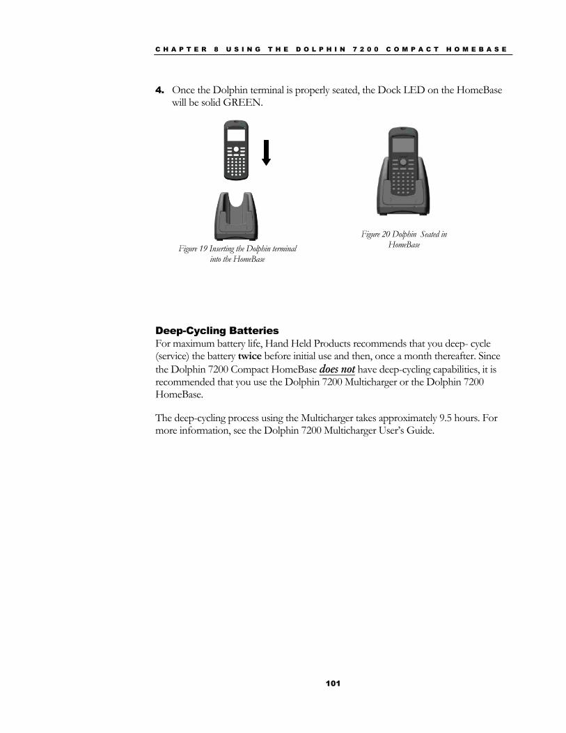
C H A P T E R 8 U S I N G T H E D O L P H I N 7 2 0 0 C O M P A C T H O M E B A S E
101
4. Once the Dolphin terminal is properly seated, the Dock LED on the HomeBase will be solid GREEN.
Deep-Cycling Batteries For maximum battery life, Hand Held Products recommends that you deep- cycle (service) the battery twice before initial use and then, once a month thereafter. Since the Dolphin 7200 Compact HomeBase does not have deep-cycling capabilities, it is recommended that you use the Dolphin 7200 Multicharger or the Dolphin 7200 HomeBase.
The deep-cycling process using the Multicharger takes approximately 9.5 hours. For more information, see the Dolphin 7200 Multicharger User’s Guide.
Figure 19 Inserting the Dolphin terminal
into the HomeBase
Figure 20 Dolphin Seated in HomeBase

C H A P T E R 8 U S I N G T H E D O L P H I N 7 2 0 0 C O M P A C T H O M E B A S E
102
Mounting the Dolphin 7200 Compact HomeBase
The Dolphin 7200 Compact HomeBase may be desk or wall-mounted for convenience and storage.
Desk Mounting: The Compact HomeBase has a DIN rail (7.5 X 35 mm) slot on the bottom to allow for secure desk attachment of the unit if desired (see figure 21).
Figure 21
Wall Mounting: The Compact HomeBase also has two DIN rail (7.5 X 35mm) slots on the back to allow for secure wall mounting of the unit if desired (see figure 22).
When using right-angle style RS232 connector cable, the DIN rails may be mounted directly to the wall. When using standard RS232 connector cables, it is recommended
Figure 22
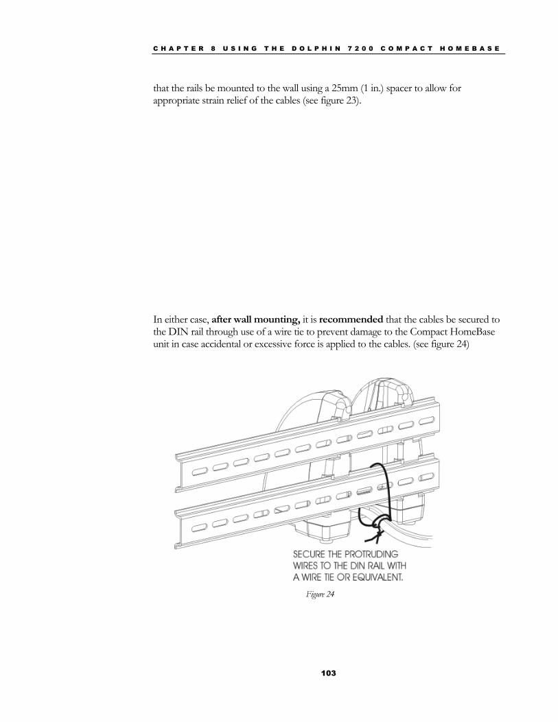
C H A P T E R 8 U S I N G T H E D O L P H I N 7 2 0 0 C O M P A C T H O M E B A S E
103
that the rails be mounted to the wall using a 25mm (1 in.) spacer to allow for appropriate strain relief of the cables (see figure 23).
In either case, after wall mounting, it is recommended that the cables be secured to the DIN rail through use of a wire tie to prevent damage to the Compact HomeBase unit in case accidental or excessive force is applied to the cables. (see figure 24)
Figure 24
C H A P T E R 8 U S I N G T H E D O L P H I N 7 2 0 0 C O M P A C T H O M E B A S E
104
Setting Up For Communications The Dolphin terminal and Dolphin Compact HomeBase support RS-232 communications through the RS-232 Main Communications Port on the back of the Dolphin 7200 Compact HomeBase. The HomeBase translates the RS-232 signals from the host computer into infrared signals to communicate with the Dolphin Terminal.
The HomeBase RS-232 interface allows the Dolphin terminal to communicate to a personal computer, modem, or any standard RS-232 device using a standard serial cable and communications software.
Follow these steps to set up the Dolphin HomeBase and Dolphin Terminal for communications:
1. Set up the Dolphin Compact HomeBase.
2. Set-up the Dolphin Terminal.
3. Follow the data transfer sequence as described by your application.
Setting up the Dolphin Compact HomeBase Set the Dolphin Compact HomeBase on any dry, stable surface such as a desktop. Before mounting the Compact HomeBase, check to ensure that all AC wall transformers have a nearby electrical outlet. Be sure to provide enough workspace with good lighting for the user to view and operate the Dolphin Terminal while it is in the HomeBase.
Connecting the Cables Connect the Compact HomeBase to the host computer or other device by plugging an RS-232 serial cable into the RS-232 Communications Port on the rear of the HomeBase. The wiring of your cable depends on whether the other device is set up as a DCE (Data Communications Equipment) or DTE (Data Terminal Equipment) device.
The HomeBase RS-232 Port is configured as a DCE device. To communicate with a DTE device such as a computer, use a standard (or straight-through) RS-232 cable. To communicate with a DCE device, use either a null modem adapter in line with a standard RS-232 cable, or a null-modem serial cable.
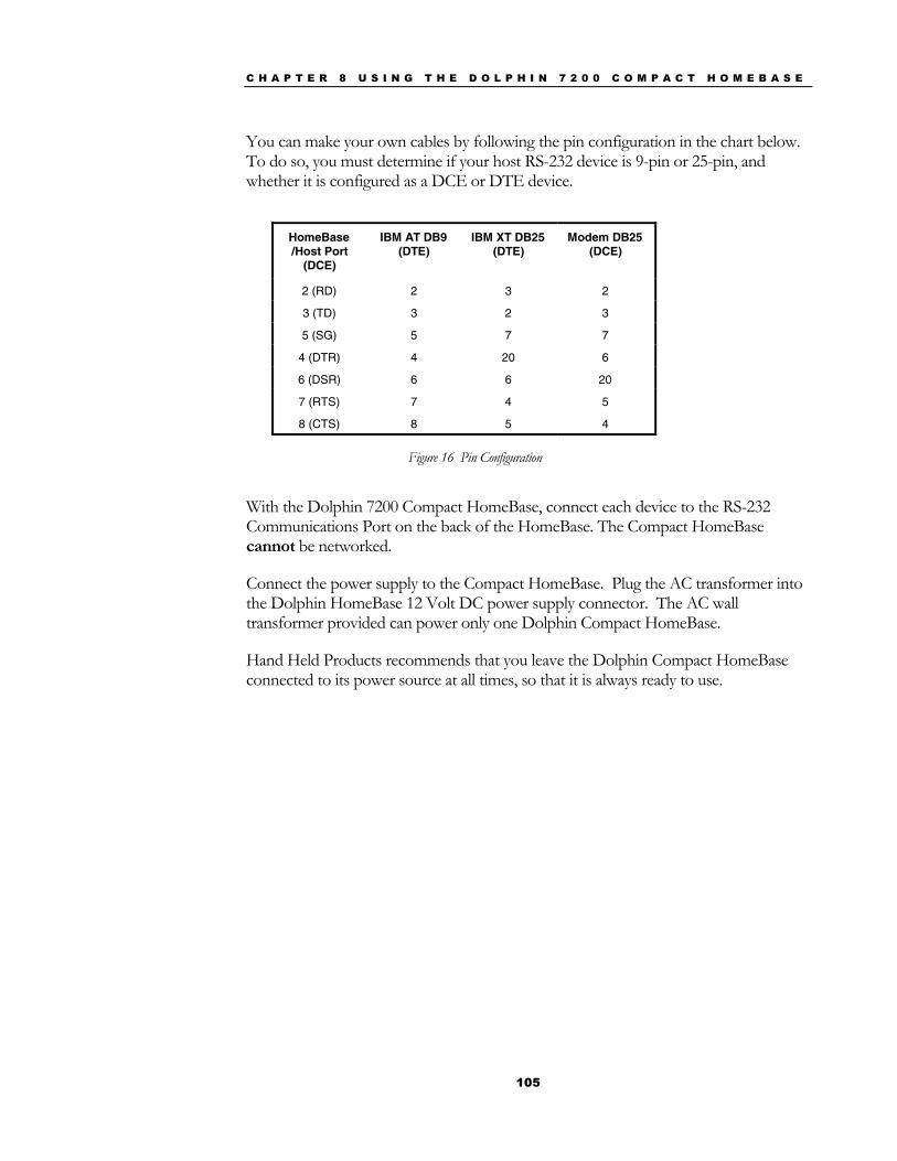
C H A P T E R 8 U S I N G T H E D O L P H I N 7 2 0 0 C O M P A C T H O M E B A S E
105
You can make your own cables by following the pin configuration in the chart below. To do so, you must determine if your host RS-232 device is 9-pin or 25-pin, and whether it is configured as a DCE or DTE device.
HomeBase /Host Port
(DCE)
IBM AT DB9 (DTE)
IBM XT DB25 (DTE)
Modem DB25 (DCE)
2 (RD) 2 3 2
3 (TD) 3 2 3
5 (SG) 5 7 7
4 (DTR) 4 20 6
6 (DSR) 6 6 20
7 (RTS) 7 4 5
8 (CTS) 8 5 4
Figure 16 Pin Configuration
With the Dolphin 7200 Compact HomeBase, connect each device to the RS-232 Communications Port on the back of the HomeBase. The Compact HomeBase cannot be networked.
Connect the power supply to the Compact HomeBase. Plug the AC transformer into the Dolphin HomeBase 12 Volt DC power supply connector. The AC wall transformer provided can power only one Dolphin Compact HomeBase.
Hand Held Products recommends that you leave the Dolphin Compact HomeBase connected to its power source at all times, so that it is always ready to use.

C H A P T E R 8 U S I N G T H E D O L P H I N 7 2 0 0 C O M P A C T H O M E B A S E
106
Communicating with the Dolphin Terminal
To communicate with the Dolphin and any other devices connected to the Compact HomeBase:
1. Insert the Dolphin into the terminal well of the HomeBase. If the Dolphin is in sleep mode, it will awaken into active state.
2. The CHARGING MAINBATT LED on the HomeBase will turn on. If the Dolphin does not turn on , or the LED does not light up, make sure that it is properly seated in the terminal well and that the power supply is properly connected to the HomeBase and plugged into a functioning AC outlet.
3. Start your application on the Dolphin terminal or the host computer. Data can then begin transmitting between the terminal and the devices connected to the Dolphin HomeBase.
When data transfer begins, the COMM LED on the Dolphin HomeBase will blink red and green. If the HomeBase will not communicate with the Dolphin, check the port connections to ensure that the HomeBase is correctly configured. See Chapter 10, Troubleshooting, for more information.

107
Chapter 9 Learning About the Dolphin OS and Development System Software Explains how to use and manage the software accompanying the Dolphin 7200 terminal.
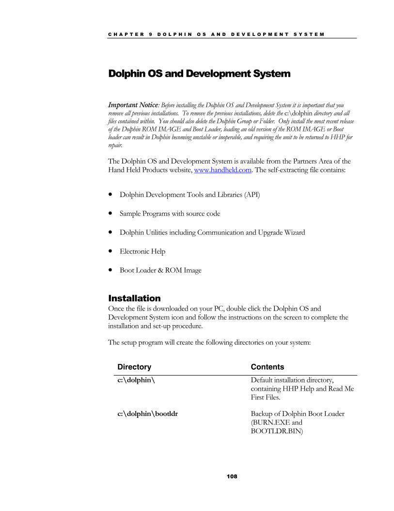
C H A P T E R 9 D O L P H I N O S A N D D E V E L O P M E N T S Y S T E M
108
Dolphin OS and Development System
Important Notice: Before installing the Dolphin OS and Development System it is important that you remove all previous installations. To remove the previous installations, delete the c:\dolphin directory and all files contained within. You should also delete the Dolphin Group or Folder. Only install the most recent release of the Dolphin ROM IMAGE and Boot Loader, loading an old version of the ROM IMAGE or Boot loader can result in Dolphin becoming unstable or inoperable, and requiring the unit to be returned to HHP for repair.
The Dolphin OS and Development System is available from the Partners Area of the Hand Held Products website, www.handheld.com. The self-extracting file contains:
• Dolphin Development Tools and Libraries (API)
• Sample Programs with source code
• Dolphin Utilities including Communication and Upgrade Wizard
• Electronic Help
• Boot Loader & ROM Image
Installation Once the file is downloaded on your PC, double click the Dolphin OS and Development System icon and follow the instructions on the screen to complete the installation and set-up procedure.
The setup program will create the following directories on your system:
Directory Contents c:\dolphin\ Default installation directory,
containing HHP Help and Read Me First Files.
c:\dolphin\bootldr Backup of Dolphin Boot Loader (BURN.EXE and BOOTLDR.BIN)
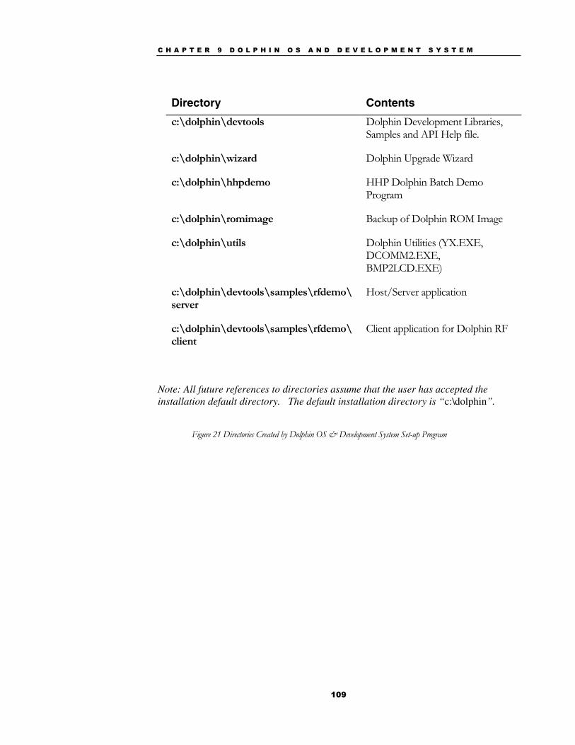
C H A P T E R 9 D O L P H I N O S A N D D E V E L O P M E N T S Y S T E M
109
Directory Contents c:\dolphin\devtools Dolphin Development Libraries,
Samples and API Help file.
c:\dolphin\wizard Dolphin Upgrade Wizard
c:\dolphin\hhpdemo HHP Dolphin Batch Demo Program
c:\dolphin\romimage Backup of Dolphin ROM Image
c:\dolphin\utils Dolphin Utilities (YX.EXE, DCOMM2.EXE, BMP2LCD.EXE)
c:\dolphin\devtools\samples\rfdemo\server
Host/Server application
c:\dolphin\devtools\samples\rfdemo\client
Client application for Dolphin RF
Note: All future references to directories assume that the user has accepted the installation default directory. The default installation directory is “c:\dolphin”.
Figure 21 Directories Created by Dolphin OS & Development System Set-up Program
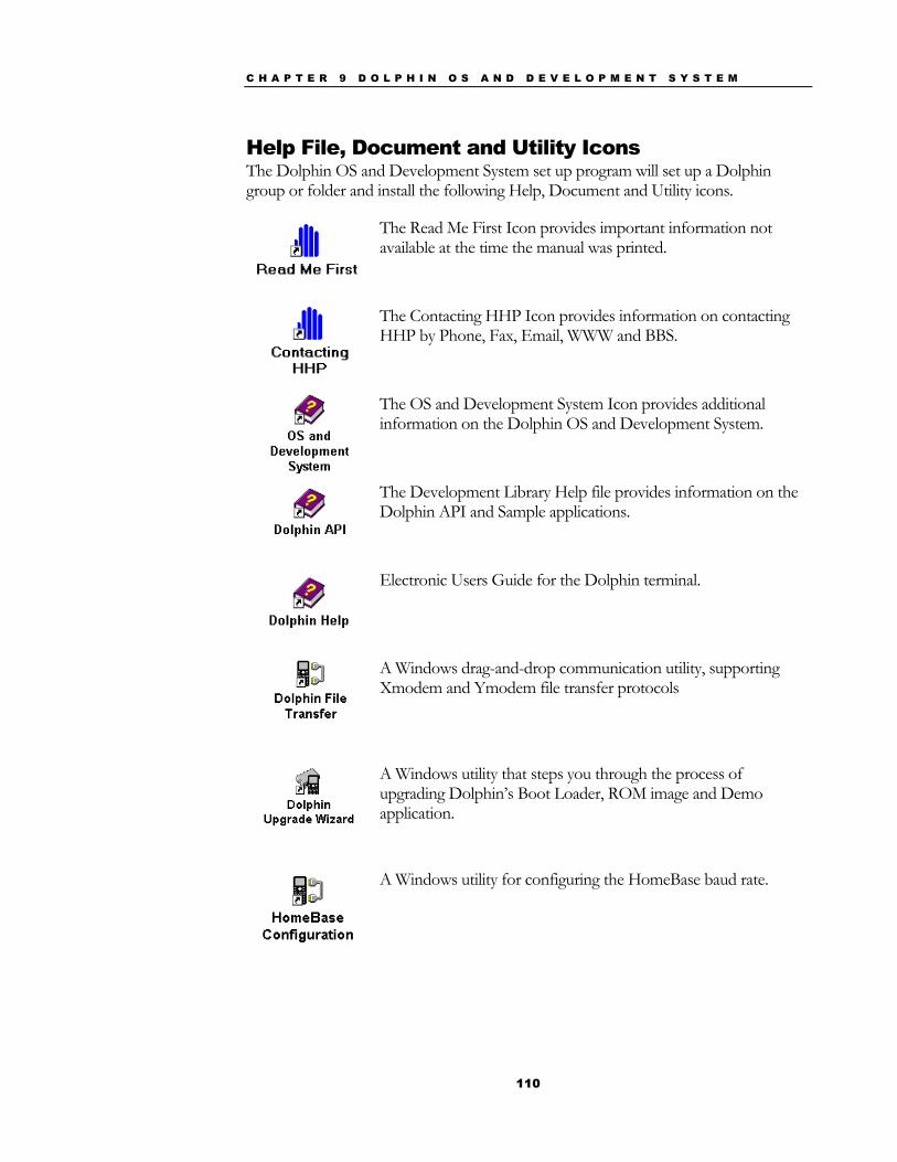
C H A P T E R 9 D O L P H I N O S A N D D E V E L O P M E N T S Y S T E M
110
Help File, Document and Utility Icons The Dolphin OS and Development System set up program will set up a Dolphin group or folder and install the following Help, Document and Utility icons.
The Read Me First Icon provides important information not available at the time the manual was printed.
The Contacting HHP Icon provides information on contacting HHP by Phone, Fax, Email, WWW and BBS.
The OS and Development System Icon provides additional information on the Dolphin OS and Development System.
The Development Library Help file provides information on the Dolphin API and Sample applications.
Electronic Users Guide for the Dolphin terminal.
A Windows drag-and-drop communication utility, supporting Xmodem and Ymodem file transfer protocols
A Windows utility that steps you through the process of upgrading Dolphin’s Boot Loader, ROM image and Demo application.
A Windows utility for configuring the HomeBase baud rate.
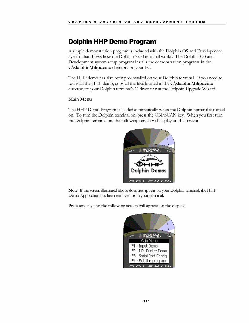
C H A P T E R 9 D O L P H I N O S A N D D E V E L O P M E N T S Y S T E M
111
Dolphin HHP Demo Program A simple demonstration program is included with the Dolphin OS and Development System that shows how the Dolphin 7200 terminal works. The Dolphin OS and Development system setup program installs the demonstration programs in the c:\dolphin\hhpdemo directory on your PC.
The HHP demo has also been pre-installed on your Dolphin terminal. If you need to re-install the HHP demo, copy all the files located in the c:\dolphin\hhpdemo directory to your Dolphin terminal’s C: drive or run the Dolphin Upgrade Wizard.
Main Menu
The HHP Demo Program is loaded automatically when the Dolphin terminal is turned on. To turn the Dolphin terminal on, press the ON/SCAN key. When you first turn the Dolphin terminal on, the following screen will display on the screen:
Note: If the screen illustrated above does not appear on your Dolphin terminal, the HHP Demo Application has been removed from your terminal.
Press any key and the following screen will appear on the display:
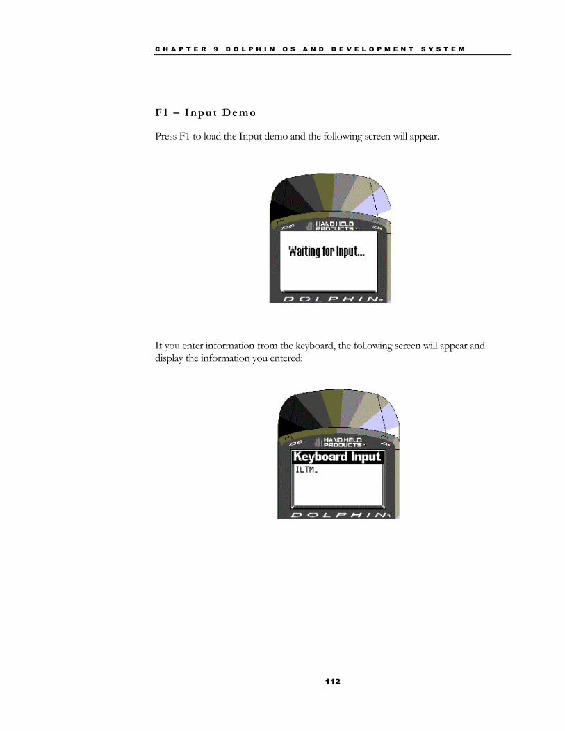
C H A P T E R 9 D O L P H I N O S A N D D E V E L O P M E N T S Y S T E M
112
F 1 – I n p u t D e m o
Press F1 to load the Input demo and the following screen will appear.
If you enter information from the keyboard, the following screen will appear and display the information you entered:
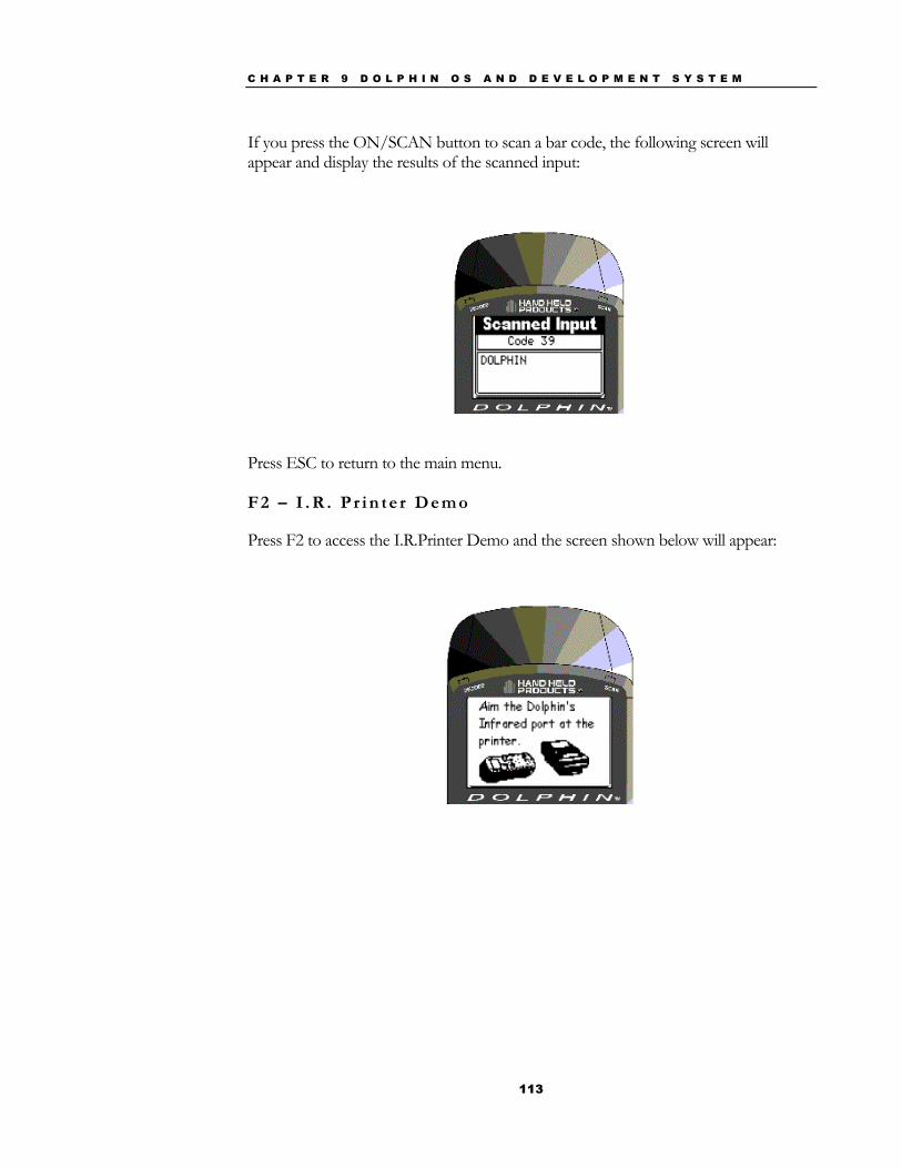
C H A P T E R 9 D O L P H I N O S A N D D E V E L O P M E N T S Y S T E M
113
If you press the ON/SCAN button to scan a bar code, the following screen will appear and display the results of the scanned input:
Press ESC to return to the main menu. F 2 – I . R . P r i n t e r D e m o
Press F2 to access the I.R.Printer Demo and the screen shown below will appear:
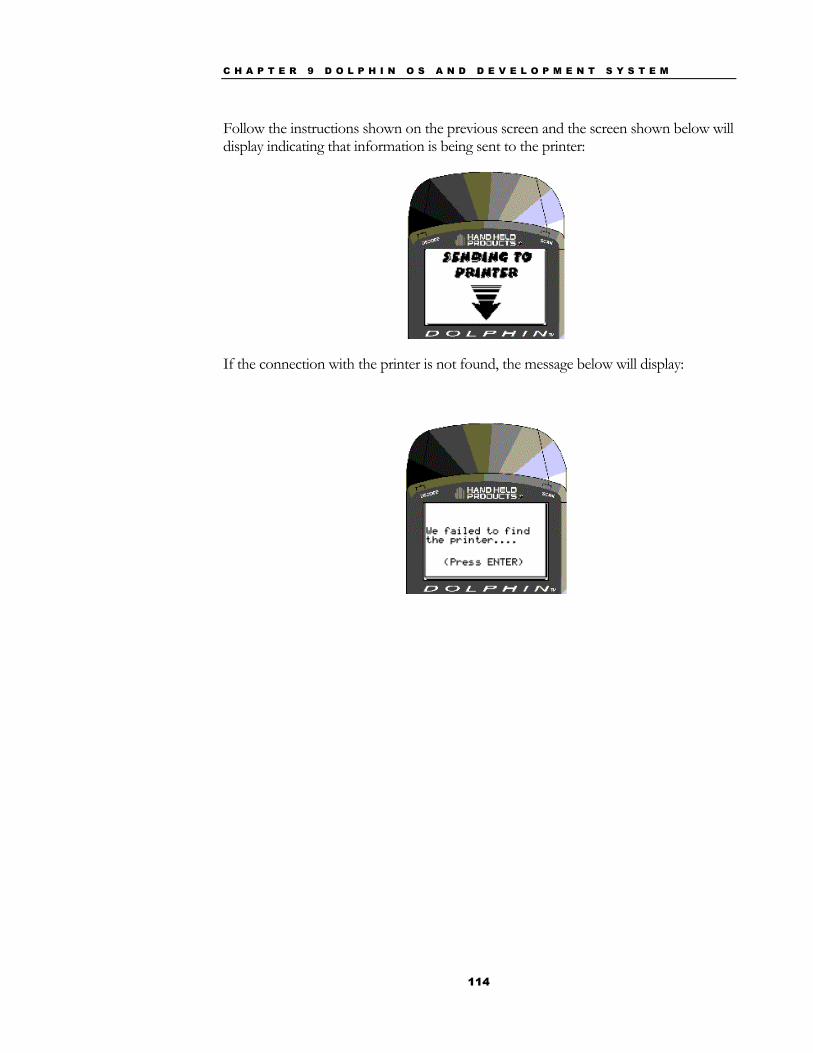
C H A P T E R 9 D O L P H I N O S A N D D E V E L O P M E N T S Y S T E M
114
Follow the instructions shown on the previous screen and the screen shown below will display indicating that information is being sent to the printer:
If the connection with the printer is not found, the message below will display:
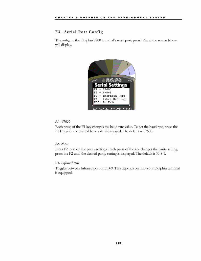
C H A P T E R 9 D O L P H I N O S A N D D E V E L O P M E N T S Y S T E M
115
F 3 – S e r i a l P o r t C o n f i g
To configure the Dolphin 7200 terminal’s serial port, press F3 and the screen below will display.
F1 – 57600
Each press of the F1 key changes the baud rate value. To set the baud rate, press the F1 key until the desired baud rate is displayed. The default is 57600.
F2– N-8-1
Press F2 to select the parity settings. Each press of the key changes the parity setting; press the F2 until the desired parity setting is displayed. The default is N-8-1.
F3– Infrared Port
Toggles between Infrared port or DB-9. This depends on how your Dolphin terminal is equipped.
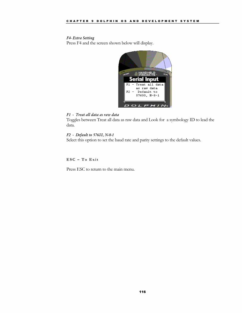
C H A P T E R 9 D O L P H I N O S A N D D E V E L O P M E N T S Y S T E M
116
F4- Extra Setting Press F4 and the screen shown below will display.
F1 - Treat all data as raw data Toggles between Treat all data as raw data and Look for a symbology ID to lead the data.
F2 - Default to 57600, N-8-1 Select this option to set the baud rate and parity settings to the default values.
E S C – T o E x i t
Press ESC to return to the main menu.

C H A P T E R 9 D O L P H I N O S A N D D E V E L O P M E N T S Y S T E M
117
Scanning A Barcode The Dolphin Terminal comes with demonstration software that allows you to scan barcodes immediately. A sample barcode is illustrated below for you to use for practice.
Hold the Dolphin terminal approximately 2 inches away from the sample barcode. Press the ON/SCAN key to begin scanning. Move the Dolphin terminal back and forward until the unit gets a good read. The Dolphin terminal will “beep,” and the laser will turn off when a good read is obtained. The decode LED will turn green The Dolphin terminal will show a translation of the sample barcode on the LCD window, which should appear similar to the following illustration.
HHP SCAN TEST Press F1 for setup ESC to quit
Label: DOLPHIN
Type:
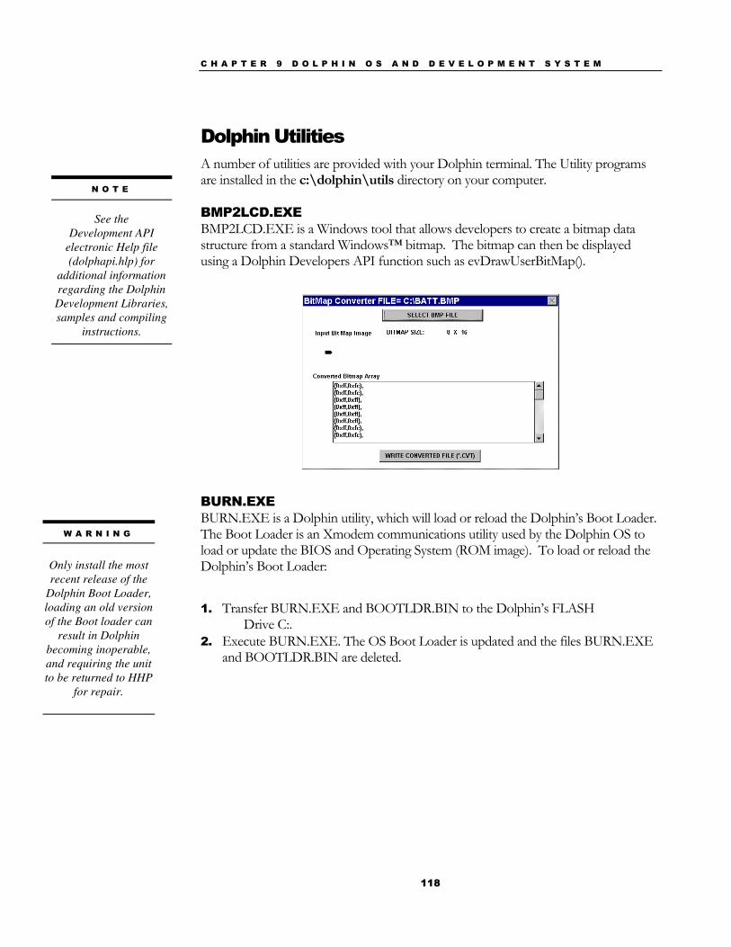
C H A P T E R 9 D O L P H I N O S A N D D E V E L O P M E N T S Y S T E M
118
Dolphin Utilities A number of utilities are provided with your Dolphin terminal. The Utility programs are installed in the c:\dolphin\utils directory on your computer.
BMP2LCD.EXE BMP2LCD.EXE is a Windows tool that allows developers to create a bitmap data structure from a standard Windows™ bitmap. The bitmap can then be displayed using a Dolphin Developers API function such as evDrawUserBitMap().
BURN.EXE BURN.EXE is a Dolphin utility, which will load or reload the Dolphin’s Boot Loader. The Boot Loader is an Xmodem communications utility used by the Dolphin OS to load or update the BIOS and Operating System (ROM image). To load or reload the Dolphin’s Boot Loader:
1. Transfer BURN.EXE and BOOTLDR.BIN to the Dolphin’s FLASH Drive C:.
2. Execute BURN.EXE. The OS Boot Loader is updated and the files BURN.EXE and BOOTLDR.BIN are deleted.
N O T E
See the Development API
electronic Help file (dolphapi.hlp) for
additional information regarding the Dolphin Development Libraries, samples and compiling
instructions.
W A R N I N G
Only install the most recent release of the
Dolphin Boot Loader, loading an old version of the Boot loader can
result in Dolphin becoming inoperable, and requiring the unit to be returned to HHP
for repair.
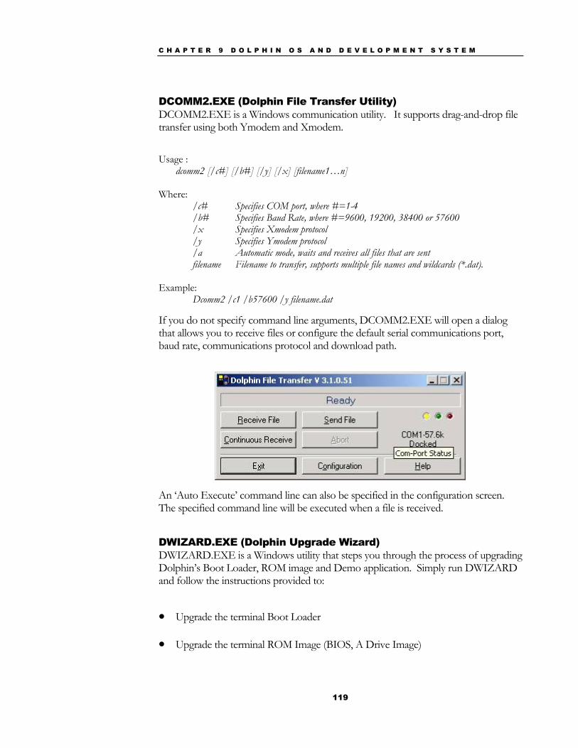
C H A P T E R 9 D O L P H I N O S A N D D E V E L O P M E N T S Y S T E M
119
DCOMM2.EXE (Dolphin File Transfer Utility) DCOMM2.EXE is a Windows communication utility. It supports drag-and-drop file transfer using both Ymodem and Xmodem.
Usage :
dcomm2 [/c#] [/b#] [/y] [/x] [filename1…n] Where:
/c# Specifies COM port, where #=1-4 /b# Specifies Baud Rate, where #=9600, 19200, 38400 or 57600 /x Specifies Xmodem protocol /y Specifies Ymodem protocol /a Automatic mode, waits and receives all files that are sent filename Filename to transfer, supports multiple file names and wildcards (*.dat).
Example: Dcomm2 /c1 /b57600 /y filename.dat If you do not specify command line arguments, DCOMM2.EXE will open a dialog that allows you to receive files or configure the default serial communications port, baud rate, communications protocol and download path.
An ‘Auto Execute’ command line can also be specified in the configuration screen. The specified command line will be executed when a file is received.
DWIZARD.EXE (Dolphin Upgrade Wizard) DWIZARD.EXE is a Windows utility that steps you through the process of upgrading Dolphin’s Boot Loader, ROM image and Demo application. Simply run DWIZARD and follow the instructions provided to:
• Upgrade the terminal Boot Loader
• Upgrade the terminal ROM Image (BIOS, A Drive Image)
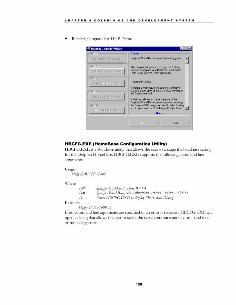
C H A P T E R 9 D O L P H I N O S A N D D E V E L O P M E N T S Y S T E M
120
• Reinstall/Upgrade the HHP Demo
HBCFG.EXE (HomeBase Configuration Utility) HBCFG.EXE is a Windows utility that allows the user to change the baud rate setting for the Dolphin HomeBase. HBCFG.EXE supports the following command line arguments:
Usage: hbcfg [/c#] [/I] [/b#]
Where:
/c#: Specifies COM port, where #=1-4 /b#: Specifies Baud Rate, where #=9600, 19200, 38400 or 57600 /I: Forces HBCFG.EXE to display ‘Please wait Dialog’
Example: hbcfg /c1 /b57600 /I If no command line arguments are specified or an error is detected, HBCFG.EXE will open a dialog that allows the user to select the serial communications port, baud rate, or run a diagnostic.
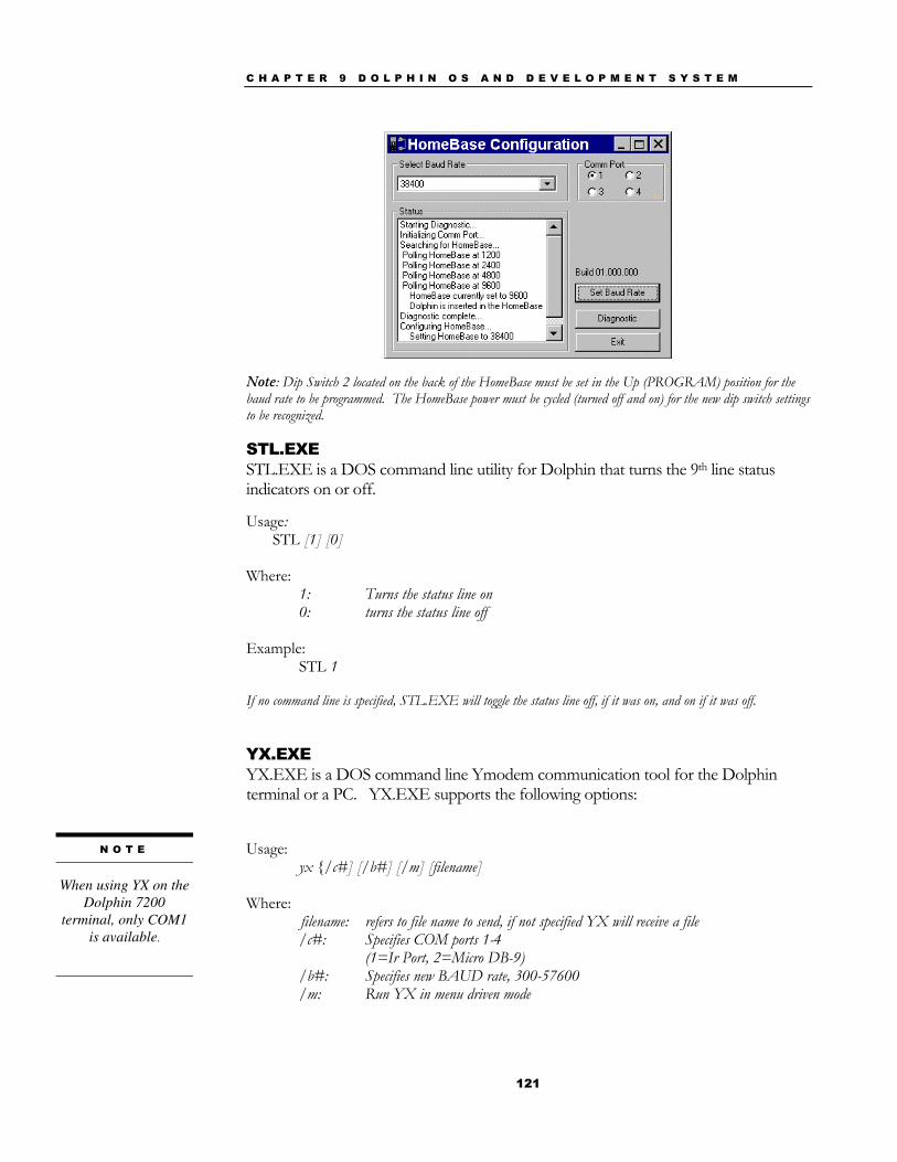
C H A P T E R 9 D O L P H I N O S A N D D E V E L O P M E N T S Y S T E M
121
Note: Dip Switch 2 located on the back of the HomeBase must be set in the Up (PROGRAM) position for the baud rate to be programmed. The HomeBase power must be cycled (turned off and on) for the new dip switch settings to be recognized.
STL.EXE STL.EXE is a DOS command line utility for Dolphin that turns the 9th line status indicators on or off. Usage:
STL [1] [0] Where:
1: Turns the status line on 0: turns the status line off
Example: STL 1 If no command line is specified, STL.EXE will toggle the status line off, if it was on, and on if it was off. YX.EXE YX.EXE is a DOS command line Ymodem communication tool for the Dolphin terminal or a PC. YX.EXE supports the following options:
Usage:
yx {/c#] [/b#] [/m] [filename] Where:
filename: refers to file name to send, if not specified YX will receive a file /c#: Specifies COM ports 1-4 (1=Ir Port, 2=Micro DB-9) /b#: Specifies new BAUD rate, 300-57600 /m: Run YX in menu driven mode
N O T E
When using YX on the
Dolphin 7200 terminal, only COM1
is available.
C H A P T E R 9 D O L P H I N O S A N D D E V E L O P M E N T S Y S T E M
122
Examples: yx /b57600 autoexec.bat yx yx /m yx /c2 The default baud rate for the YX.EXE utility is 57600. For your convenience, batch files are included on the Dolphin terminal to make sending data at a higher baud rate easier.
To send at 38400, enter <YF> instead of YX/b38400.
To send at 57600, enter <YFF> instead of YX/b57600.
ZZZ.EXE ZZZ.EXE is a DOS command line utility for Dolphin that places the terminal into sleep mode.
Note – The terminal can not be placed in sleep mode while it is in the HomeBase. While in a HomeBase, the terminal must be on so it can monitor the battery status.
C H A P T E R 9 D O L P H I N O S A N D D E V E L O P M E N T S Y S T E M
123
The following Utilities are included in the Dolphin ROM image and are automatically loaded when the terminal boots. They are NOT included on the Dolphin OS and Development System Disk.
Utility Description
EVS.EXE Enhanced Video System (EVS) is a TSR that traps standard video BIOS (INT 10H) calls, and overlays hardware-specific support for the Dolphin’s LCD. In addition, EVS provides application and system level Status line support.
POWERMON.EXE POWERMON.EXE is a TSR that monitors battery status and power usage. POWERMON.EXE is automatically loaded when the terminal boots.
Dolphin Application Development
Compiling Applications for the Dolphin Dolphin application development is straightforward. Since Dolphin is DOS-compatible, most of the application can be tested on a desktop computer.
Although Dolphin is DOS-compatible, it provides many unique features that are not built into most PCs. For example, it has an integrated bar code scanner. The Dolphin libraries provide an API that allows an application to use these features. There are four libraries provided for linking into applications:
• dolphins.lib for small memory models
• dolphinm.lib for medium memory models
• dolphinc.lib for compact memory models
• dolphinl.lib for large memory models
The header file, dolphin.h, in the c:\dolphin\devtools\ directory contains useful declarations for using these libraries.
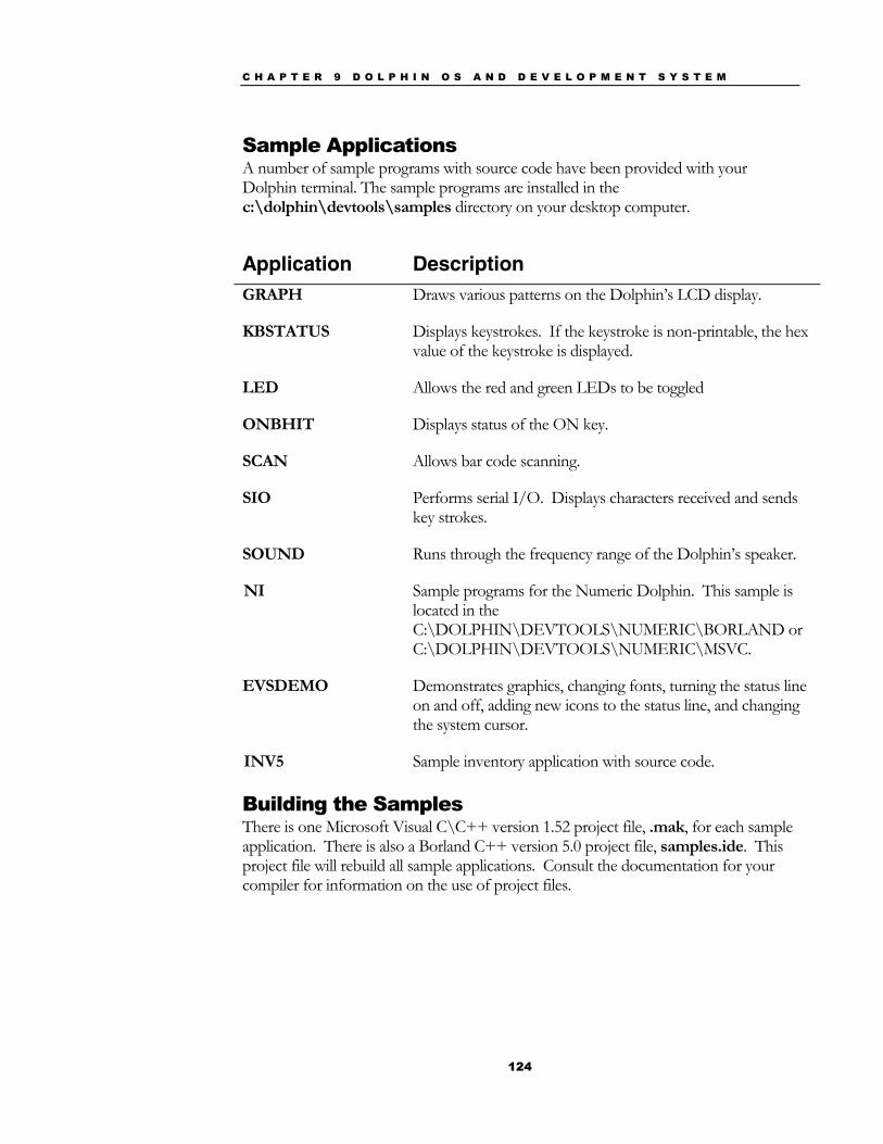
C H A P T E R 9 D O L P H I N O S A N D D E V E L O P M E N T S Y S T E M
124
Sample Applications A number of sample programs with source code have been provided with your Dolphin terminal. The sample programs are installed in the c:\dolphin\devtools\samples directory on your desktop computer.
Application Description GRAPH Draws various patterns on the Dolphin’s LCD display.
KBSTATUS Displays keystrokes. If the keystroke is non-printable, the hex value of the keystroke is displayed.
LED Allows the red and green LEDs to be toggled
ONBHIT Displays status of the ON key.
SCAN Allows bar code scanning.
SIO Performs serial I/O. Displays characters received and sends key strokes.
SOUND Runs through the frequency range of the Dolphin’s speaker.
NI Sample programs for the Numeric Dolphin. This sample is located in the C:\DOLPHIN\DEVTOOLS\NUMERIC\BORLAND or C:\DOLPHIN\DEVTOOLS\NUMERIC\MSVC.
EVSDEMO Demonstrates graphics, changing fonts, turning the status line on and off, adding new icons to the status line, and changing the system cursor.
INV5 Sample inventory application with source code.
Building the Samples There is one Microsoft Visual C\C++ version 1.52 project file, .mak, for each sample application. There is also a Borland C++ version 5.0 project file, samples.ide. This project file will rebuild all sample applications. Consult the documentation for your compiler for information on the use of project files.
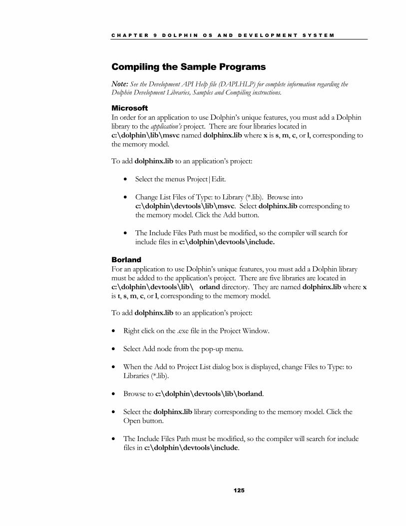
C H A P T E R 9 D O L P H I N O S A N D D E V E L O P M E N T S Y S T E M
125
Compiling the Sample Programs
Note: See the Development API Help file (DAPI.HLP) for complete information regarding the Dolphin Development Libraries, Samples and Compiling instructions.
Microsoft In order for an application to use Dolphin’s unique features, you must add a Dolphin library to the application’s project. There are four libraries located in c:\dolphin\lib\msvc named dolphinx.lib where x is s, m, c, or l, corresponding to the memory model.
To add dolphinx.lib to an application’s project:
• Select the menus Project|Edit.
• Change List Files of Type: to Library (*.lib). Browse into c:\dolphin\devtools\lib\msvc. Select dolphinx.lib corresponding to the memory model. Click the Add button.
• The Include Files Path must be modified, so the compiler will search for include files in c:\dolphin\devtools\include.
Borland For an application to use Dolphin’s unique features, you must add a Dolphin library must be added to the application’s project. There are five libraries are located in c:\dolphin\devtools\lib\�orland directory. They are named dolphinx.lib where x is t, s, m, c, or l, corresponding to the memory model.
To add dolphinx.lib to an application’s project:
• Right click on the .exe file in the Project Window.
• Select Add node from the pop-up menu.
• When the Add to Project List dialog box is displayed, change Files to Type: to Libraries (*.lib).
• Browse to c:\dolphin\devtools\lib\borland.
• Select the dolphinx.lib library corresponding to the memory model. Click the Open button.
• The Include Files Path must be modified, so the compiler will search for include files in c:\dolphin\devtools\include.

C H A P T E R 9 D O L P H I N O S A N D D E V E L O P M E N T S Y S T E M
126
Transferring Files to or from Dolphin Transferring files between your Dolphin terminal and a desktop PC is easy with the YX.EXE utility or the Dolphin File Transfer program.
Using the YX.EXE Utility The YX.EXE utility, installed in the directory c:\dolphin\utils, performs RS-232 file transfers using Ymodem batch protocol. In addition, YX.EXE is preloaded on the Dolphin’s A drive. This program can be run by entering commands at the DOS prompt or by accessing a menu.
YX.EXE supports the following options:
Usage : yx [/b#] [/m] [filename] [com port]
Where:
filename: refers to file name to send, if not specified YX will receive a file /b#: Specifies new BAUD rate, 300-57600 /m: Run YX in menu driven mode /c#: Specifies COM ports 1-9 (1=Ir Port, 2=Micro DB-9)
Examples: yx /b57600 autoexec.bat yx yx /m yx/c2
The default baud rate for the YX.EXE utility is 57600. For your convenience, batch files are included on the Dolphin terminal to make sending data at a higher baud rate easier.
To send at 38400, enter <YF> instead of YX /b38400.
To send at 57600, enter <YFF> instead of YX /b57600.
Using the Dolphin File Transfer Program Open the Dolphin program group in Windows Explorer and copy the Dolphin File Transfer shortcut to your PC’s desktop. Putting the shortcut on your desktop simplifies the file transfer process.
N O T E
When using YX on the Dolphin 7200 with Ir Only terminal, only COM1 is available.
C H A P T E R 9 D O L P H I N O S A N D D E V E L O P M E N T S Y S T E M
127
Sending a File to the Dolphin 1. Open the Dolphin File Transfer Program Configuration dialog box. Check to
make sure the baud rate is set at 57600. This is the default for YX.EXE. Close the Configuration dialog box and exit the Dolphin File Transfer program. To change the baud rate, see the section on “Sending Files at a Higher Rate” on the next page.
2. Open Windows Explorer. Resize and move the window so that you can see both Explorer and the Dolphin File Transfer shortcut on your desktop.
3. In Windows Explorer, select the file to be transferred and, while holding down the left mouse button, drag and drop the file on the Dolphin File Transfer shortcut on the desktop. This opens the Dolphin File Transfer program.
4. At the Dolphin’s C: prompt, enter <YX>.
5. Press <ENTER> on the Dolphin terminal to begin the file transfer. The COMM LED on the Dolphin HomeBase will blink red and green during the transfer. You can also view the progress of the file transfer on the Dolphin screen and Dolphin File Transfer program window.
Sending a File From Dolphin to Your PC 1. Double-click on the Dolphin File Transfer shortcut to open the program.
2. Open the Configuration dialog box. Check to make ensure the baud rate is set at 57600.
3. At the Dolphin’s C: prompt, enter <YX> [Filename].
4. Click on the Receive File button.
5. Press <ENTER> on the Dolphin terminal to begin the file transfer. The COMM LED on the Dolphin HomeBase will blink red and green during the transfer. You can also view the progress of the file transfer on the Dolphin screen and in the Dolphin File Transfer program window.
Sending Files At A Higher Rate A batch file containing command lines for sending and receiving files at higher baud rates is also loaded on the Dolphin terminal. To send at a higher rate, the Dolphin HomeBase must be programmed at the higher baud rate. Configuration Switch 2 should be in the down position. Refer to the section on Baud Rate Selection in Configuring a Single Dolphin HomeBase or Creating a HomeBase Network later in this chapter.
• To send at 38400 baud rate, enter <YF> at the DOS prompt instead of <YX>.
N O T E
The configuration switches are checked
at power up. Changes in the
switch settings will not be recognized
until power is cycled.

C H A P T E R 9 D O L P H I N O S A N D D E V E L O P M E N T S Y S T E M
128
• To send at 57600 baud rate, enter <YFF> at the DOS prompt.
Using the Dolphin File Transfer Program and YX in Menu Mode You can also use YX in menu mode to send and receive files from the Dolphin to your PC and vice versa with the Dolphin File Transfer program and YX.EXE on the PC.
Sending Files to the Dolphin
To use a menu for sending files to the Dolphin, follow these steps:
1. Open the Configuration dialog box. Check to make sure the baud rate is set at 57600. This is the default for YX.EXE.
2. Enter <YX /M> at the Dolphin terminal’s DOS prompt.
3. Press <ENTER> and the menu below will appear on your Dolphin terminal’s screen:
4. In Windows Explorer, select the file to be transferred and, while holding down the left mouse button, drag and drop the file on the Dolphin File Transfer shortcut on the desktop. This opens the Dolphin File Transfer program.
5. Press <F2> to begin the file transfer. If you are using a HomeBase to transfer files, the COMM LED will blink red and green during the transfer. You can also view the progress of the file transfer on the Dolphin screen and status bar in the Dolphin File Transfer program window.
Sending Files From the Dolphin To Your PC
Port = 1 Baud Rate = 9600 F1 – Send File F2 - Receive File F3 - Set Baud Rate F4 - Choose Port Q - Quit
N O T E
When using the menu, press <F3> to change to a higher baud rate.
If you are using a HomeBase to transfer
files, be sure to set Configuration Switch 2 on the
HomeBase in the up position.
C H A P T E R 9 D O L P H I N O S A N D D E V E L O P M E N T S Y S T E M
129
1. Double-click on the Dolphin File Transfer shortcut to open the program.
2. Open the Configuration dialog box. Check to make sure the baud rate is set at 57600.
3. Enter <YX /M> at the Dolphin terminal’s DOS prompt.
4. Press <ENTER> and the menu below will appear on your Dolphin terminal’s screen:
5. Click on the Receive File button.
6. Press <F1> on your Dolphin terminal and then enter the name of the file. Press <ENTER>. If you are using a HomeBase to transfer files, the COMM LED on the Dolphin HomeBase will blink red and green during the transfer. You can also view the progress of the file transfer on the Dolphin screen and status bar in the Dolphin File Transfer program window.
Dolphin EVS Engine The EVS engine provides bit-mapped graphics support for the Dolphin LCD. EVS is the primary interface between an application and BIOS graphics functions. The EVS engine consists of three basic parts:
1. A TSR (EVS.EXE) that traps standard video BIOS (INT 10H) calls, and overlays hardware specific support for the Dolphin LCD.
2. A set of API routines that allow easy access to the EVS specific routines. These functions have been merged into the standard Dolphin Development API and are documented in the Dolphin API Help file (DAPI.HLP).
3. Application and system level Status line support.
The EVS engine eliminates the need for an application to directly access the hardware layer. The EVS engine maintains an image of the display in memory (118 pixels wide by 73 pixels tall). All application screen access (read/write) is filtered so as to write to the display image rather to the hardware. The EVS engine then updates the hardware (e.g. writes to the display) as necessary. This process allows for support of a single display plane that combines graphics and text.
For more on the Dolphin EVS Engine, see the Dolphin OS and Development System electronic help file.

C H A P T E R 9 D O L P H I N O S A N D D E V E L O P M E N T S Y S T E M
130
Dolphin ROM Image and Boot Loader Upgrading the Dolphin ROM Image Important Notice: Before installing the Dolphin OS and Development System, you must remove all previous installations. To do this, delete the C:\DOLPHIN directory and all files contained within as well as the Dolphin Group or Folder. Only install the most recent release of the Dolphin ROM IMAGE and Boot Loader. Loading an old version of the ROM IMAGE or Boot Loader can make the Dolphin unstable or inoperable, and requiring you to return the unit to HHP for repair.
The Dolphin terminal has a Boot Loader incorporated that allows the developer to upgrade or reload the ROM IMAGE.
Follow these steps to manually reload the ROM IMAGE and Operating System from DOS:
1. Verify that Configuration Switch 2 on the back of the Dolphin HomeBase is set to “Fixed BPS” and Switch 1 is set to “Single”. Power must be turned off and then on to accept the new dip switch settings.
2. Make sure the serial cable is properly installed and power is properly connected to the HomeBase. Make sure no other communications programs are running on the PC.
3. Start the Dolphin Boot Loader. Hold down the “7” and “9” keys with one hand. With your other hand, press and release the “ON/SCAN”, “SHIFT” and “BKSP” keys. Release the “7” and “9” keys. You should see the screen below. If not, repeat step three.
4. Press “3” to select Baud rate. Press “1” to set baud rate to 57600.
SYS Utilities X.XX 1) Download 2) Launch Bios 3) Set Baud Rate Baud: 57600
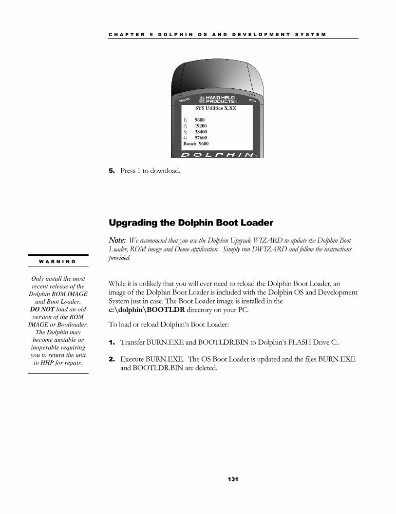
C H A P T E R 9 D O L P H I N O S A N D D E V E L O P M E N T S Y S T E M
131
5. Press 1 to download.
Upgrading the Dolphin Boot Loader Note: We recommend that you use the Dolphin Upgrade WIZARD to update the Dolphin Boot Loader, ROM image and Demo application. Simply run DWIZARD and follow the instructions provided.
While it is unlikely that you will ever need to reload the Dolphin Boot Loader, an image of the Dolphin Boot Loader is included with the Dolphin OS and Development System just in case. The Boot Loader image is installed in the c:\dolphin\BOOTLDR directory on your PC. To load or reload Dolphin’s Boot Loader: 1. Transfer BURN.EXE and BOOTLDR.BIN to Dolphin’s FLASH Drive C:.
2. Execute BURN.EXE. The OS Boot Loader is updated and the files BURN.EXE and BOOTLDR.BIN are deleted.
W A R N I N G
Only install the most recent release of the
Dolphin ROM IMAGE and Boot Loader.
DO NOT load an old version of the ROM
IMAGE or Bootloader. The Dolphin may
become unstable or inoperable requiring you to return the unit
to HHP for repair.
SYS Utilities X.XX 1) 9600 2) 19200 3) 38400 4) 57600 Baud: 9600
132
Chapter 10 Troubleshooting and Warranty Information Dolphin® 7200 Terminal Describes troubleshooting tips, solutions for problems you may encounter with the Dolphin 7200 terminal or HomeBase and warranty information.
C H A P T E R 1 0 T R O U B L E S H O O T I N G A N D W A R R A N T Y I N F O R M A T I O N F O R D O L P H I N 7 2 0 0 T E R M I N A L
133
Just In Case The Dolphin 7200 terminal and Dolphin HomeBase are both designed to provide years of trouble-free use. Both products are covered by a one-year limited warranty. This chapter includes troubleshooting tips, warranty information, describes how to obtain technical support.
Before Calling For Application Support If you have problems with either the Dolphin terminal or HomeBase, review the list of symptoms and solutions included in this chapter. If the problem isn’t listed in this chapter, contact your Reseller or Hand Held Products’ Application Support Department for assistance.
Troubleshooting the Dolphin Terminal and HomeBase This table describes some of the common problems/symptoms and solutions that you could encounter while using your Dolphin terminal or Dolphin HomeBase. If you need further assistance with troubleshooting your terminal, contact your HHP Authorized Reseller.
If You Have This Problem/Symptom
Try This:
The display is blank, the Dolphin terminal will not turn on.
Is the battery is low? Recharge or replace it with a known good battery. Reset the Dolphin terminal.
When booting up the Dolphin, I see the message ‘CMOS MEM size wrong’ for a second or two and the unit continues to boot. Is there something wrong with my unit?
When the Dolphin’s internal NiMH battery is not charged or run down, this message will display and the terminal’s settings are reset to their default values. This includes the date and time which is reset to January 1, 1980 and 12:00 AM. The terminal is fine. You simply need to recharge the internal battery and reset the Dolphin’s date and time. To do this, insert a fully charged battery in the Dolphin and then use the DOS Date and Time function to set the correct date and time. The internal back-up battery requires a minimum of 5 hours of charging time in order to perform and maintain the system as described in Chapter 2 of this manual.
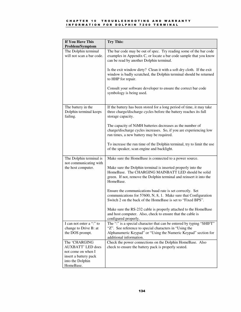
C H A P T E R 1 0 T R O U B L E S H O O T I N G A N D W A R R A N T Y I N F O R M A T I O N F O R D O L P H I N 7 2 0 0 T E R M I N A L
134
If You Have This Problem/Symptom
Try This:
The Dolphin terminal will not scan a bar code.
The bar code may be out of spec. Try reading some of the bar code examples in Appendix C, or locate a bar code sample that you know can be read by another Dolphin terminal. Is the exit window dirty? Clean it with a soft dry cloth. If the exit window is badly scratched, the Dolphin terminal should be returned to HHP for repair. Consult your software developer to ensure the correct bar code symbology is being used.
The battery in the Dolphin terminal keeps failing.
If the battery has been stored for a long period of time, it may take three charge/discharge cycles before the battery reaches its full storage capacity. The capacity of NiMH batteries decreases as the number of charge/discharge cycles increases. So, if you are experiencing low run times, a new battery may be required. To increase the run time of the Dolphin terminal, try to limit the use of the speaker, scan engine and backlight.
The Dolphin terminal is not communicating with the host computer.
Make sure the HomeBase is connected to a power source. Make sure the Dolphin terminal is inserted properly into the HomeBase. The CHARGING MAINBATT LED should be solid green. If not, remove the Dolphin terminal and reinsert it into the HomeBase. Ensure the communications baud rate is set correctly. Set communications for 57600, N, 8, 1. Make sure that Configuration Switch 2 on the back of the HomeBase is set to “Fixed BPS”. Make sure the RS-232 cable is properly attached to the HomeBase and host computer. Also, check to ensure that the cable is configured properly.
I can not enter a “:” to change to Drive B: at the DOS prompt.
The “:” is a special character that can be entered by typing “SHIFT” “Z”. See reference to special characters in “Using the Alphanumeric Keypad” or “Using the Numeric Keypad” section for additional information.
The ‘CHARGING AUXBATT’ LED does not come on when I insert a battery pack into the Dolphin HomeBase.
Check the power connections on the Dolphin HomeBase. Also check to ensure the battery pack is properly seated.
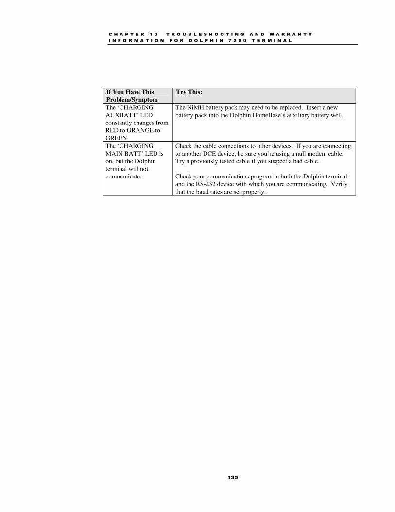
C H A P T E R 1 0 T R O U B L E S H O O T I N G A N D W A R R A N T Y I N F O R M A T I O N F O R D O L P H I N 7 2 0 0 T E R M I N A L
135
If You Have This Problem/Symptom
Try This:
The ‘CHARGING AUXBATT’ LED constantly changes from RED to ORANGE to GREEN.
The NiMH battery pack may need to be replaced. Insert a new battery pack into the Dolphin HomeBase’s auxiliary battery well.
The ‘CHARGING MAIN BATT’ LED is on, but the Dolphin terminal will not communicate.
Check the cable connections to other devices. If you are connecting to another DCE device, be sure you’re using a null modem cable. Try a previously tested cable if you suspect a bad cable. Check your communications program in both the Dolphin terminal and the RS-232 device with which you are communicating. Verify that the baud rates are set properly.
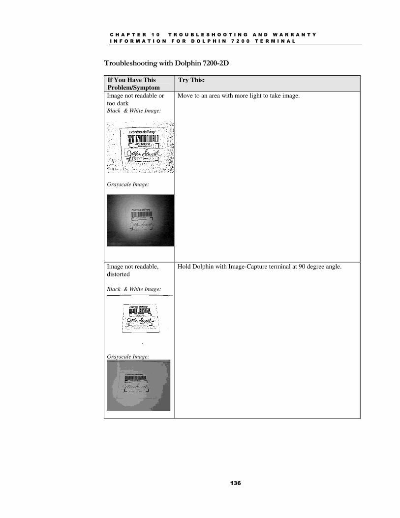
C H A P T E R 1 0 T R O U B L E S H O O T I N G A N D W A R R A N T Y I N F O R M A T I O N F O R D O L P H I N 7 2 0 0 T E R M I N A L
136
Troubleshooting with Dolphin 7200-2D
If You Have This Problem/Symptom
Try This:
Image not readable or too dark Black & White Image:
Grayscale Image:
Move to an area with more light to take image.
Image not readable, distorted Black & White Image:
Grayscale Image:
Hold Dolphin with Image-Capture terminal at 90 degree angle.

C H A P T E R 1 0 T R O U B L E S H O O T I N G A N D W A R R A N T Y I N F O R M A T I O N F O R D O L P H I N 7 2 0 0 T E R M I N A L
137
If You Have This Problem/Symptom
Try This:
Image not readable, cut off Black and White Image: Grayscale Image:
You are holding terminal too close to subject. Hold the terminal at a 90 degree angle and move it further away from the subject.
Image not readable, dirty lens Black and White Image:
Grayscale Image:
Wipe lens with clean, lint free cloth.

C H A P T E R 1 0 T R O U B L E S H O O T I N G A N D W A R R A N T Y I N F O R M A T I O N F O R D O L P H I N 7 2 0 0 T E R M I N A L
138
If You Have This Problem/Symptom
Try This:
Image not readable; too small. Black and White Image:
Grayscale Image:
You are holding the terminal too far away from the subject. Hold the terminal at a 90 degree angle and move it closer to the subject.
Image not readable due to reflection Black and White Image:
Grayscale Image:
Adjust the angle at which you are holding the Dolphin terminal to avoid a reflection.
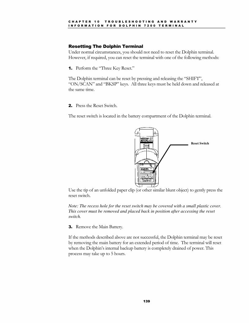
C H A P T E R 1 0 T R O U B L E S H O O T I N G A N D W A R R A N T Y I N F O R M A T I O N F O R D O L P H I N 7 2 0 0 T E R M I N A L
139
Resetting The Dolphin Terminal Under normal circumstances, you should not need to reset the Dolphin terminal. However, if required, you can reset the terminal with one of the following methods:
1. Perform the “Three Key Reset.”
The Dolphin terminal can be reset by pressing and releasing the “SHIFT”, “ON/SCAN” and “BKSP” keys. All three keys must be held down and released at the same time.
2. Press the Reset Switch.
The reset switch is located in the battery compartment of the Dolphin terminal.
Use the tip of an unfolded paper clip (or other similar blunt object) to gently press the reset switch.
Note: The recess hole for the reset switch may be covered with a small plastic cover. This cover must be removed and placed back in position after accessing the reset switch. 3. Remove the Main Battery.
If the methods described above are not successful, the Dolphin terminal may be reset by removing the main battery for an extended period of time. The terminal will reset when the Dolphin’s internal backup battery is completely drained of power. This process may take up to 5 hours.
Reset Switch

C H A P T E R 1 0 T R O U B L E S H O O T I N G A N D W A R R A N T Y I N F O R M A T I O N F O R D O L P H I N 7 2 0 0 T E R M I N A L
140
Warranty Information
Who Is Covered By The Warranty
Limited Warranty Welch Allyn Data Collection, Inc., d/b/a Hand Held Products ("HHP") warrants its products to be free from defects in materials and workmanship and to conform to HHP’s published specifications applicable to the products purchased at the time of shipment. This warranty does not cover any HHP product which is (i) improperly installed or used; (ii) damaged by accident or negligence, including failure to follow the proper maintenance, service, and cleaning schedule; or (iii) damaged as a result of (A) modification or alteration by the purchaser or other party, (B) excessive voltage or current supplied to or drawn from the interface connections, (C) static electricity or electro-static discharge, (D) operation under conditions beyond the specified operating parameters, or (E) repair or service of the product by anyone other than HHP or its authorized representatives.
This warranty shall extend from the time of shipment for the duration published by HHP for the product at the time of purchase ("Warranty Period"). Any defective product must be returned (at purchaser’s expense) during the Warranty Period to HHP’s factory or authorized service center for inspection. No product will be accepted by HHP without a Return Materials Authorization, which may be obtained by contacting HHP. In the event that the product is returned to HHP or its authorized service center within the Warranty Period and HHP determines to its satisfaction that the product is defective due to defects in materials or workmanship, HHP, at its sole option, will either repair or replace the product without charge, except for return shipping to HHP.
EXCEPT AS MAY BE OTHERWISE PROVIDED BY APPLICABLE LAW, THE FOREGOING WARRANTY IS IN LIEU OF ALL OTHER COVENANTS OR WARRANTIES, EITHER EXPRESSED OR IMPLIED, ORAL OR WRITTEN, INCLUDING, WITHOUT LIMITATION, ANY IMPLIED WARRANTIES OF MERCHANTABILITY OR FITNESS FOR A PARTICULAR PURPOSE.
HHP’S RESPONSIBILITY AND PURCHASER’S EXCLUSIVE REMEDY UNDER THIS WARRANTY IS LIMITED TO THE REPAIR OR REPLACEMENT OF THE DEFECTIVE PRODUCT. IN NO EVENT SHALL HHP BE LIABLE FOR INDIRECT, INCIDENTAL, OR CONSEQUENTIAL DAMAGES, AND, IN NO EVENT, SHALL ANY LIABILITY OF HHP ARISING IN CONNECTION WITH ANY PRODUCT SOLD HEREUNDER
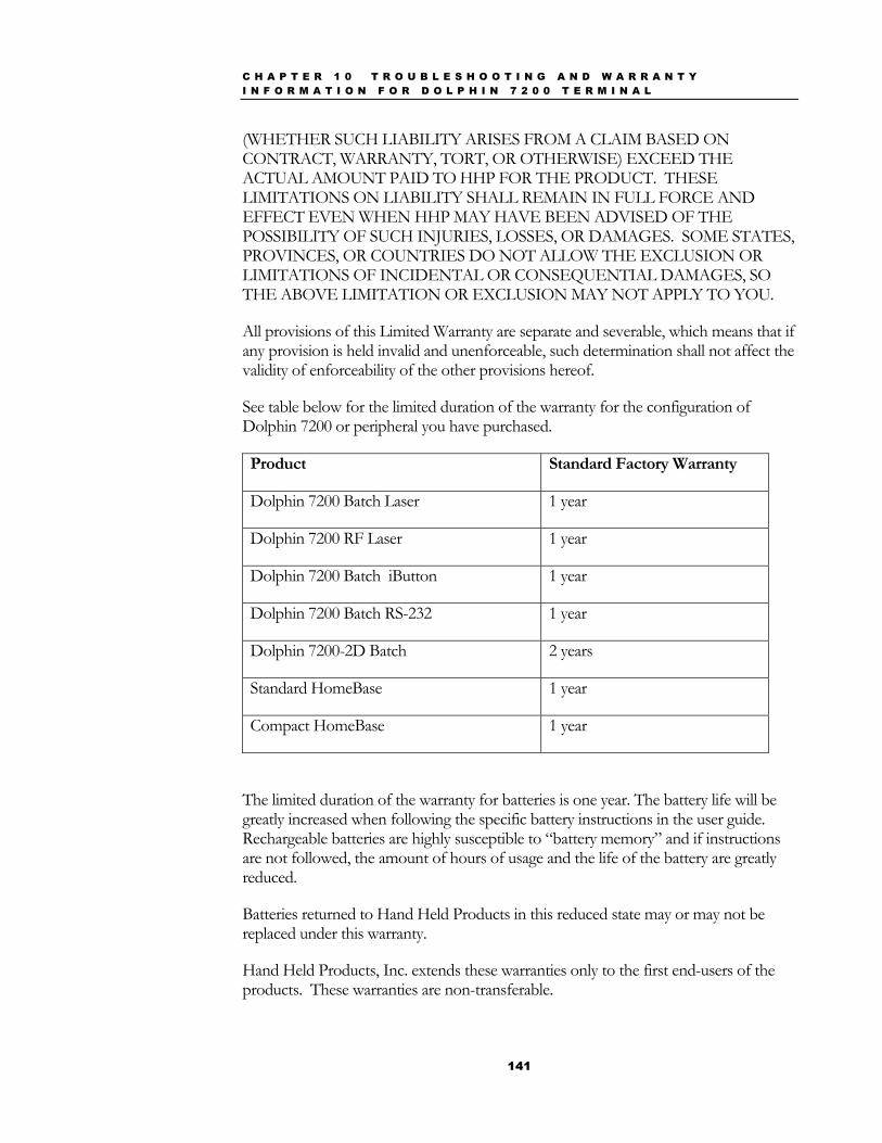
C H A P T E R 1 0 T R O U B L E S H O O T I N G A N D W A R R A N T Y I N F O R M A T I O N F O R D O L P H I N 7 2 0 0 T E R M I N A L
141
(WHETHER SUCH LIABILITY ARISES FROM A CLAIM BASED ON CONTRACT, WARRANTY, TORT, OR OTHERWISE) EXCEED THE ACTUAL AMOUNT PAID TO HHP FOR THE PRODUCT. THESE LIMITATIONS ON LIABILITY SHALL REMAIN IN FULL FORCE AND EFFECT EVEN WHEN HHP MAY HAVE BEEN ADVISED OF THE POSSIBILITY OF SUCH INJURIES, LOSSES, OR DAMAGES. SOME STATES, PROVINCES, OR COUNTRIES DO NOT ALLOW THE EXCLUSION OR LIMITATIONS OF INCIDENTAL OR CONSEQUENTIAL DAMAGES, SO THE ABOVE LIMITATION OR EXCLUSION MAY NOT APPLY TO YOU.
All provisions of this Limited Warranty are separate and severable, which means that if any provision is held invalid and unenforceable, such determination shall not affect the validity of enforceability of the other provisions hereof.
See table below for the limited duration of the warranty for the configuration of Dolphin 7200 or peripheral you have purchased.
Product Standard Factory Warranty
Dolphin 7200 Batch Laser 1 year
Dolphin 7200 RF Laser 1 year
Dolphin 7200 Batch iButton 1 year
Dolphin 7200 Batch RS-232 1 year
Dolphin 7200-2D Batch 2 years
Standard HomeBase 1 year
Compact HomeBase 1 year
The limited duration of the warranty for batteries is one year. The battery life will be greatly increased when following the specific battery instructions in the user guide. Rechargeable batteries are highly susceptible to “battery memory” and if instructions are not followed, the amount of hours of usage and the life of the battery are greatly reduced.
Batteries returned to Hand Held Products in this reduced state may or may not be replaced under this warranty.
Hand Held Products, Inc. extends these warranties only to the first end-users of the products. These warranties are non-transferable.
C H A P T E R 1 0 T R O U B L E S H O O T I N G A N D W A R R A N T Y I N F O R M A T I O N F O R D O L P H I N 7 2 0 0 T E R M I N A L
142
How Problems Should Be Handled Should the Dolphin terminal or HomeBase prove to be defective within the warranty period, return the product, as described in the RMA procedures below, and we will, at our option, repair or replace the product, to whatever extent HHP deems necessary to restore the product to proper operating condition, without any charge to you.
Return Information If you purchased the product from an Authorized Hand Held Products Reseller, contact the Reseller with the unit’s serial number. Your Reseller will contact Hand Held, on your behalf, to arrange for the unit to be serviced.
If you purchased the product directly from Hand Held, or have been instructed by your Reseller to contact Hand Held directly, call the Customer Services Department in your area to request a Repair Maintenance Authorization (RMA) number. Note: An RMA number is not needed for service at the Europe, the Middle East, Africa or United Kingdom repair facilities.
North America:
(TEL) 1-(800)-782-4263
(FAX)+1-(704)-566-9904
Latin America
(TEL)+1-(941)-263-7600
(FAX)+1-(941)-263-9689
Europe, Middle East and Africa:
(TEL)+31-40 24 24 486
(FAX)+31-40 24 25 672
The United Kingdom:
(TEL)+44 (0) 1925 240 055
(FAX)+44 (0) 1925 245 225
Asia Pacific
(TEL) +852 2511 3050
(FAX) +852 2511 3557
N O T E
You must have an RMA number to
receive service on your product at
the repair facility for North and
South, Asia and the Pacific Rim.
C H A P T E R 1 0 T R O U B L E S H O O T I N G A N D W A R R A N T Y I N F O R M A T I O N F O R D O L P H I N 7 2 0 0 T E R M I N A L
143
You must have an RMA number to receive service from the repair facility for North and South America, Asia and the Pacific Rim. Failure to obtain an RMA number before shipping your product to this repair facility may result in the product being returned without being serviced. RMA numbers are valid for 30 days within the United States and 60 days Internationally.
When calling for service at any of our repair facilities, please be prepared to give the following information:
• Product’s type and serial number
• Brief description of problem
• Dated Proof-of-Purchase
Place the product in its original packaging with a copy of your original invoice and ship the product prepaid to the appropriate address below:
North and South America, Asia, Pacific Rim
Hand Held Products Product Service Department
7510 East Independence Blvd., #100 Charlotte, NC 28227-9411
RMA Number:__________________________
Europe, Middle East and Africa :
HHP Product Service Department Hondsruglaan 87D
5628 DB Eindhoven The Netherlands
The United Kingdom :
HHP Product Service Department 1st Floor
Dallam Court Dallam Lane
Warrington, Cheshire WA2 7LT United Kingdom
If your equipment is still covered under the initial end-user’s product warranty, please notify the Customer Services Representative when you call. Please include a copy of
C H A P T E R 1 0 T R O U B L E S H O O T I N G A N D W A R R A N T Y I N F O R M A T I O N F O R D O L P H I N 7 2 0 0 T E R M I N A L
144
the original invoice in the package to avoid possible service delays. For your protection, we recommend you insure any equipment being sent to HHP.
After repair or replacement of the equipment, Hand Held Products will ship the product, at our cost, to your location. Non-warranty repairs will be returned, at the customer’s expense, unless otherwise requested. Units currently under a service agreement will be shipped per the service agreement.
Please make note of the RMA number (if required) before shipping and the product’s serial number for future reference.
How To Extend Your Warranty Hand Held Products offers a variety of service plans on our hardware products. These agreements offer continued coverage for your equipment after the initial warranty expires. For more information, contact your Hand Held sales representative, customer account representative or the Product Service Marketing Manager or your Authorized Reseller.
Application Support If you have a question or problem with your Dolphin terminal or Dolphin HomeBase, you can get technical assistance from Hand Held’s Application Support department.
Application Support – North and South America, Asia and Pacific Rim:
(TEL) 1-(800) 782-4263 (FAX) 1-(704) 532-4191 8:30 a.m. and 5:30 p.m., Eastern Time, Monday through Friday Application Support – Europe, Middle East and Africa : (TEL)+31-40 24 24 486 (FAX)+31-40 24 25 672 9 a.m. – 5 p.m., Central European Time, Monday through Friday Application Support – The United Kingdom : (TEL) : INT+ 44 1925 240055 (FAX) : INT+ 44 1925 631280 9 a.m. – 5:30 p.m., UK Time, Monday through Friday
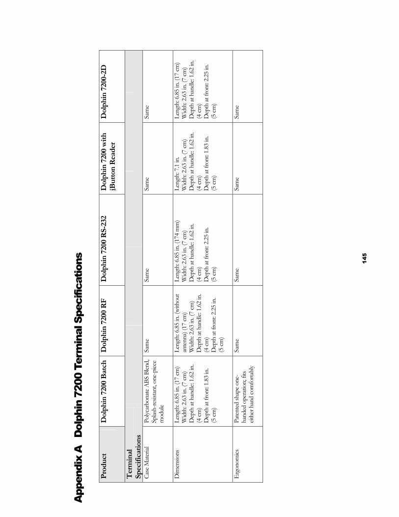
145
App
endi
x A
D
olph
in 7
200
Term
inal
Spe
cific
atio
ns
Pr
oduc
t D
olph
in 7
200
Batc
h
Dol
phin
720
0 R
F D
olph
in 7
200
RS-
232
Dol
phin
720
0 w
ith
iBut
ton
Rea
der
Dol
phin
720
0-2D
Ter
min
al
Spec
ifica
tions
Case
Mat
erial
Po
lycar
bona
te A
BS B
lend,
Sp
lash-
resis
tant
, one
-piec
e m
odul
e
Sam
e
Sa
me
Sam
e Sa
me
Dim
ensio
ns
Leng
th: 6
.85 in
. (17
cm)
Wid
th: 2
.63 in
. (7
cm)
Dep
th at
han
dle:
1.62
in.
(4 cm
) D
epth
at fr
ont:
1.83
in.
(5 cm
)
Leng
th: 6
.85 in
. (wi
thou
t an
tenn
a) (1
7 cm
) W
idth
: 2.63
in. (
7 cm
) D
epth
at h
andl
e: 1.6
2 in
.
(4
cm)
Dep
th at
fron
t: 2.2
5 in
.
(5 cm
)
Leng
th: 6
.85 in
. (17
4 m
m)
Wid
th: 2
.63 in
. (7
cm)
Dep
th at
han
dle:
1.62
in.
(4 cm
) D
epth
at fr
ont:
2.25
in.
(5 cm
)
Leng
th: 7
.1 in
. W
idth
: 2.63
in. (
7 cm
) D
epth
at h
andl
e: 1.6
2 in
. (4
cm)
Dep
th at
fron
t: 1.8
3 in
.
(5 cm
)
Leng
th: 6
.85 in
. (17
cm)
Wid
th: 2
.63 in
. (7
cm)
Dep
th at
han
dle:
1.62
in.
(4 cm
) D
epth
at fr
ont:
2.25
in.
(5 cm
)
Ergo
nom
ics
Pate
nted
shap
e one
-ha
nded
ope
ratio
n; fi
ts eit
her h
and
com
forta
bly
Sam
e
Sa
me
Sam
e Sa
me
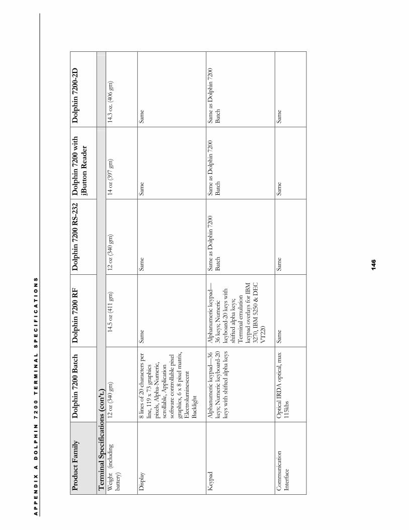
AP
PE
ND
IX
A
D
OL
PH
IN
7
20
0
TE
RM
IN
AL
S
PE
CI
FI
CA
TI
ON
S
14
6
Pr
oduc
t Fam
ily
Dol
phin
720
0 Ba
tch
Dol
phin
720
0 R
F D
olph
in 7
200
RS-
232
Dol
phin
720
0 w
ith
iBut
ton
Rea
der
Dol
phin
720
0-2D
Ter
min
al S
peci
ficat
ions
(con
’t.)
W
eight
(in
cludi
ng
batte
ry)
12 o
z (34
0 gm
)
14.5
oz (
411
gm)
12 o
z (34
0 gm
) 14
oz (
397
gm)
14.3
oz. (
406
gm)
Disp
lay
8 lin
es o
f 20
char
acte
rs p
er
line,
119
x 73
gra
phics
pi
xels,
Alp
ha-N
umer
ic,
scro
llabl
e, A
pplic
atio
n so
ftwar
e con
trolla
ble p
ixel
grap
hics
, 6 x
8 p
ixel m
atrix
, El
ectro
lum
ines
cent
Ba
cklig
ht
Sam
e
Sam
e Sa
me
Sam
e
Key
pad
Alp
hanu
mer
ic ke
ypad
—36
ke
ys; N
umer
ic ke
yboa
rd-2
0 ke
ys w
ith sh
ifted
alph
a key
s
Alp
hanu
mer
ic ke
ypad
—36
key
s; N
umer
ic ke
yboa
rd-2
0 ke
ys w
ith
shift
ed al
pha k
eys;
Term
inal
emul
atio
n ke
ypad
ove
rlays
for I
BM
3270
, IBM
525
0 &
DEC
V
T220
Sam
e as D
olph
in 7
200
Batc
h Sa
me a
s Dol
phin
720
0 Ba
tch
Sam
e as D
olph
in 7
200
Batc
h
Com
mun
icatio
n
Inte
rface
O
ptica
l IRD
A o
ptica
l, max
11
5kbs
Sa
me
Sam
e
Sam
e
Sam
e
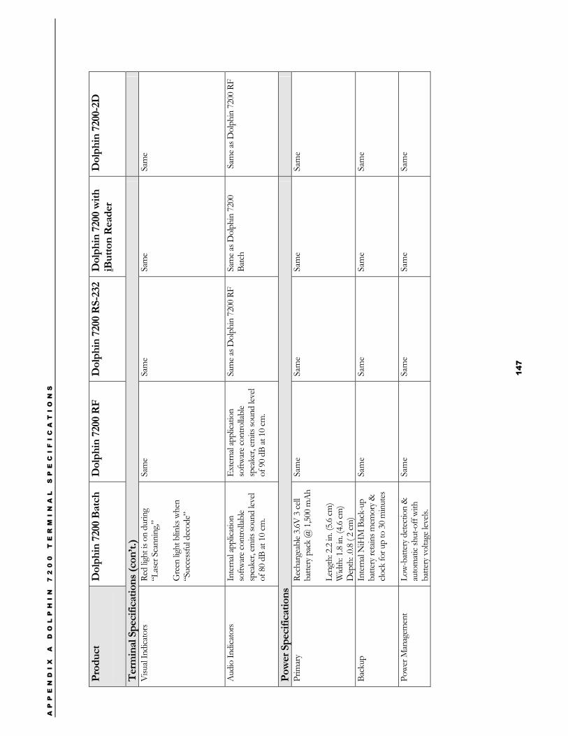
AP
PE
ND
IX
A
D
OL
PH
IN
7
20
0
TE
RM
IN
AL
S
PE
CI
FI
CA
TI
ON
S
14
7
Prod
uct
Dol
phin
720
0 Ba
tch
Dol
phin
720
0 R
F D
olph
in 7
200
RS-
232
Dol
phin
720
0 w
ith
iBut
ton
Rea
der
Dol
phin
720
0-2D
Ter
min
al S
peci
ficat
ions
(con
’t.)
V
isual
Indi
cato
rs
Red
light
is o
n du
ring
“Las
er S
cann
ing,”
Gre
en lig
ht b
links
whe
n “S
ucce
ssfu
l dec
ode”
Sam
e
Sam
e
Sam
e
Sam
e
Aud
io In
dica
tors
In
tern
al ap
plica
tion
softw
are c
ontro
llabl
e sp
eake
r, em
its so
und
level
of 8
0 dB
at 1
0 cm
.
Exte
rnal
appl
icatio
n so
ftwar
e con
trolla
ble
spea
ker,
emits
soun
d lev
el of
90
dB at
10
cm.
Sam
e as D
olph
in 7
200
RF
Sa
me a
s Dol
phin
720
0 Ba
tch
Sam
e as D
olph
in 7
200
RF
Pow
er S
peci
ficat
ions
Prim
ary
Rech
arge
able
3.6V
3 ce
ll ba
ttery
pac
k @
1,50
0 m
Ah
Leng
th: 2
.2 in
. (5.6
cm)
Wid
th: 1
.8 in
. (4.6
cm)
Dep
th: .0
.8 ( 2
cm)
Sam
e Sa
me
Sam
e Sa
me
Back
up
Inte
rnal
NiH
M B
ack-
up
batte
ry re
tain
s mem
ory &
clo
ck fo
r up
to 3
0 m
inut
es
Sam
e Sa
me
Sam
e Sa
me
Powe
r Man
agem
ent
Low-
batte
ry d
etec
tion
&
auto
mat
ic sh
ut-o
ff wi
th
batte
ry v
olta
ge le
vels.
Sam
e Sa
me
Sam
e Sa
me
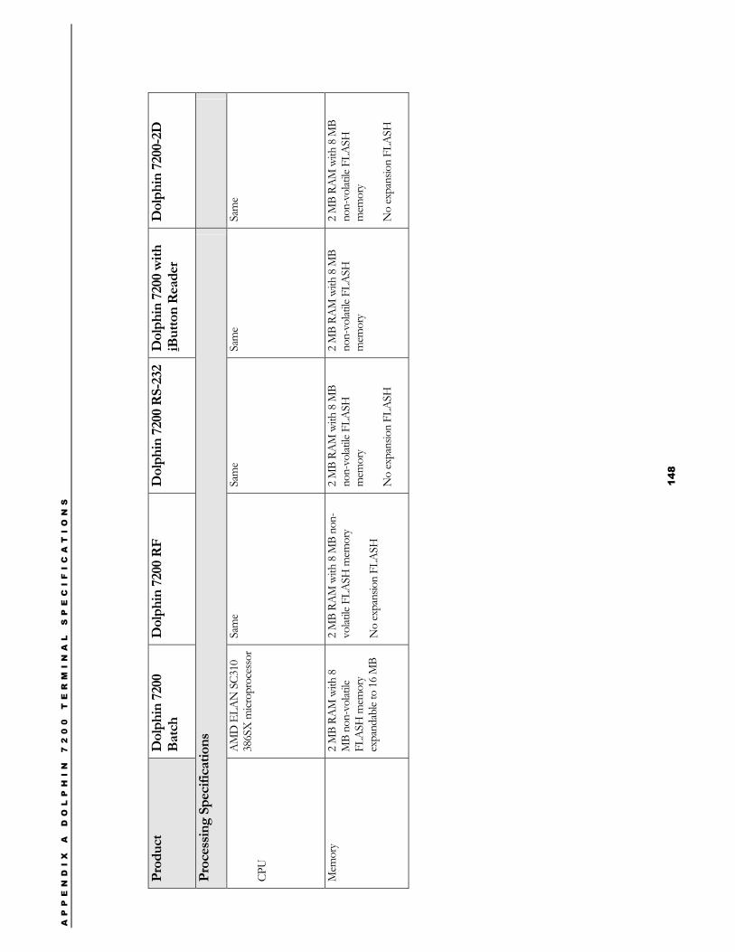
AP
PE
ND
IX
A
D
OL
PH
IN
7
20
0
TE
RM
IN
AL
S
PE
CI
FI
CA
TI
ON
S
14
8
Pr
oduc
t D
olph
in 7
200
Batc
h
Dol
phin
720
0 R
F D
olph
in 7
200
RS-
232
Dol
phin
720
0 w
ith
iBut
ton
Rea
der
Dol
phin
720
0-2D
Proc
essin
g Sp
ecifi
catio
ns
CPU
AM
D E
LAN
SC3
10
386S
X m
icrop
roce
ssor
Sam
e Sa
me
Sam
e Sa
me
Mem
ory
2 M
B RA
M w
ith 8
M
B no
n-vo
latile
FL
ASH
mem
ory
expa
ndab
le to
16
MB
2 M
B RA
M w
ith 8
MB
non-
volat
ile F
LASH
mem
ory
No
expa
nsio
n FL
ASH
2 M
B RA
M w
ith 8
MB
non-
volat
ile F
LASH
m
emor
y
No
expa
nsio
n FL
ASH
2 M
B RA
M w
ith 8
MB
non-
volat
ile F
LASH
m
emor
y
2 M
B RA
M w
ith 8
MB
non-
volat
ile F
LASH
m
emor
y
No
expa
nsio
n FL
ASH
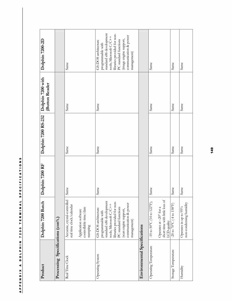
AP
PE
ND
IX
A
D
OL
PH
IN
7
20
0
TE
RM
IN
AL
S
PE
CI
FI
CA
TI
ON
S
14
9
Pr
oduc
t D
olph
in 7
200
Batc
h D
olph
in 7
200
RF
Dol
phin
720
0 R
S-23
2 D
olph
in 7
200
with
iB
utto
n R
eade
r D
olph
in 7
200-
2D
Proc
essin
g S
peci
ficat
ions
(con
’t.)
Real
Tim
e Clo
ck
Acc
urat
e, cr
ysta
l-con
trolle
d re
al tim
e clo
ck/c
alend
ar
App
licat
ion
softw
are
cont
rolla
ble t
ime/
date
sta
mpi
ng
Sam
e
Sam
e
Sam
e
Sam
e
Ope
ratin
g Sy
stem
G
S-D
OS
arch
itect
ure
prog
ram
mab
le wi
th
stand
ard
x86
deve
lopm
ent
tool
s; M
icros
oft C
/C++
lib
rarie
s pro
vide
d fo
r non
-PC
stan
dard
func
tions
(sc
an en
gine s
uppo
rt,
com
mun
icatio
n &
pow
er
man
agem
ent)
Sam
e
Sam
e Sa
me
GS-
DO
S ar
chite
ctur
e pr
ogra
mm
able
with
sta
ndar
d x8
6 de
velo
pmen
t to
ols;
Micr
osof
t C/C
++
libra
ries p
rovi
ded
for n
on-
PC st
anda
rd fu
nctio
ns
(imag
e eng
ine s
uppo
rt,
com
mun
icatio
n &
pow
er
man
agem
ent)
Env
ironm
enta
l Spe
cific
atio
ns
Ope
ratin
g Te
mpe
ratu
re
-10
to 5
0°C
(14
to 1
22°F
);
Ope
rate
s at –
20° f
or a
shor
t tim
e with
little
loss
of
LCD
qua
lity
Sam
e Sa
me
Sam
e Sa
me
Stor
age T
empe
ratu
re
-20
to 7
0°C
(-4 to
158
°F)
Sam
e Sa
me
Sam
e Sa
me
Hum
idity
O
pera
tes i
n up
to 9
5%
non-
cond
ensin
g hu
mid
ity
Sam
e Sa
me
Sam
e Sa
me
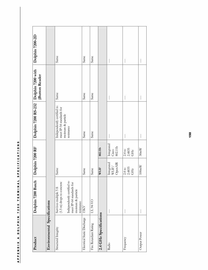
AP
PE
ND
IX
A
D
OL
PH
IN
7
20
0
TE
RM
IN
AL
S
PE
CI
FI
CA
TI
ON
S
15
0
Prod
uct
Dol
phin
720
0 Ba
tch
Dol
phin
720
0 R
F D
olph
in 7
200
RS-
232
Dol
phin
720
0 w
ith
iBut
ton
Rea
der
Dol
phin
720
0-2D
Env
ironm
enta
l Sp
ecifi
catio
ns
Stru
ctur
al In
tegr
ity
Surv
ives
mul
tiple
5 ft
(1
.5 m
) dro
ps to
conc
rete
In
depe
nden
tly ce
rtifie
d to
m
eet I
P-64
stan
dard
s for
m
oistu
re &
par
ticle
resis
tanc
e
Sam
e
In
depe
nden
tly ce
rtifie
d to
m
eet I
P-54
stan
dard
s for
m
oistu
re &
par
ticle
resis
tanc
e
Sam
e Sa
me
Elec
trica
l Sta
tic D
ischa
rge
15K
V
Sam
e Sa
me
Sam
e Sa
me
Fire
Ret
arda
nt R
atin
g U
L 94
-VO
Sa
me
Sam
e Sa
me
Sam
e
2.4
GH
z Sp
ecifi
catio
ns
WLI
F 80
2.11
b
Radi
o ---
- In
tegr
ated
W
LIF/
O
penA
IR
Inte
grat
ed
Cisc
o 80
2.11b
----
----
----
Freq
uenc
y ---
- 2.4
to
2.483
5 G
Hz
2.4 to
2.4
835
GH
z
----
----
----
Out
put P
ower
---
- 10
0mW
30
mW
---
- ---
- ---
-
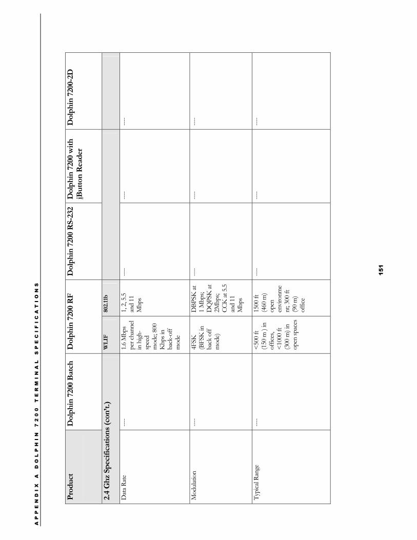
AP
PE
ND
IX
A
D
OL
PH
IN
7
20
0
TE
RM
IN
AL
S
PE
CI
FI
CA
TI
ON
S
15
1
Prod
uct
Dol
phin
720
0 Ba
tch
Dol
phin
720
0 R
F D
olph
in 7
200
RS-
232
Dol
phin
720
0 w
ith
iBut
ton
Rea
der
Dol
phin
720
0-2D
2.4
Ghz
Spe
cific
atio
ns (c
on’t.
) W
LIF
802.
11b
Dat
a Rat
e ---
- 1.6
Mbp
s pe
r cha
nnel
in h
igh-
spee
d m
ode;
800
Kbp
s in
back
-off
mod
e
1, 2,
5.5
and
11
Mbp
s
----
----
----
Mod
ulat
ion
----
4FSK
(B
FSK
in
back
off
mod
e)
DBP
SK at
1
Mbp
s; D
QPS
K at
2M
bps;
CCK
at 5
.5 an
d 11
M
bps
----
----
----
Typi
cal R
ange
----
<500
ft
(150
m )
in
offic
es,
<100
0 ft
(300
m) i
n op
en sp
aces
1500
ft
(460
m)
open
en
viro
nme
nt; 3
00 ft
(9
0 m
) of
fice
----
----
----
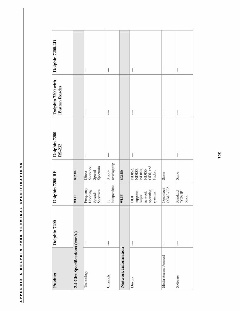
AP
PE
ND
IX
A
D
OL
PH
IN
7
20
0
TE
RM
IN
AL
S
PE
CI
FI
CA
TI
ON
S
15
2
Pr
oduc
t D
olph
in 7
200
D
olph
in 7
200
RF
Dol
phin
720
0
R
S-23
2 D
olph
in 7
200
with
iB
utto
n R
eade
r D
olph
in 7
200-
2D
2.4
Ghz
Spe
cific
atio
ns (c
on’t.
) W
LIF
802.
11b
Tech
nolo
gy
----
Freq
uenc
y H
oppi
ng
Spre
ad-
Spec
trum
Dire
ct
Sequ
ence
Sp
read
Sp
ectru
m
----
----
----
Chan
nels
----
15
inde
pend
ent
3 no
n-ov
erlap
ping
---
- ---
- ---
-
Net
wor
k In
form
atio
n W
LIF
802.
11b
Driv
ers
----
OD
I su
ppor
ts m
ajor
netw
ork
oper
atin
g sy
stem
s
ND
IS2,
ND
IS3,
ND
IS4,
ND
IS5
OD
I, an
d Pa
cket
----
----
----
Med
ia A
cces
s Pro
toco
l ---
- O
ptim
ized
CSM
A/C
A
Sam
e ---
- ---
- ---
-
Softw
are
----
Stan
dard
TC
P/IP
St
ack
Sam
e ---
- ---
- ---
-
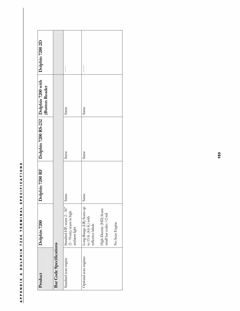
AP
PE
ND
IX
A
D
OL
PH
IN
7
20
0
TE
RM
IN
AL
S
PE
CI
FI
CA
TI
ON
S
15
3
Prod
uct
Dol
phin
720
0
Dol
phin
720
0 R
F D
olph
in 7
200
RS-
232
D
olph
in 7
200
with
iB
utto
n R
eade
r D
olph
in 7
200
2D
Bar C
ode
Spec
ifica
tions
Stan
dard
scan
engin
e St
anda
rd H
P, sc
ans 2
- 36
" (5
- 91
cm);
scan
s in
high
am
bien
t ligh
t
Sam
e Sa
me
Sam
e ---
----
Opt
iona
l sca
n en
gines
Long
-Ran
ge (L
R) S
cans
up
to 1
5 ft.
(4.6
ft.) w
ith
refle
ctiv
e lab
els
High
-Den
sity (
HD
) Sca
ns
small
bar
code
s >2
mil
No
Scan
Eng
ine
Sam
e Sa
me
Sam
e ---
-----
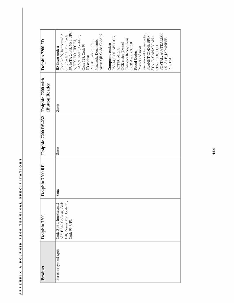
AP
PE
ND
IX
A
D
OL
PH
IN
7
20
0
TE
RM
IN
AL
S
PE
CI
FI
CA
TI
ON
S
15
4
Pr
oduc
t D
olph
in 7
200
D
olph
in 7
200
RF
Dol
phin
720
0 R
S-23
2
Dol
phin
720
0 w
ith
iBut
ton
Rea
der
Dol
phin
720
0 2D
Bar c
ode s
ymbo
l typ
es
Code
3 o
f 9, I
nter
leave
d 2
of 5
, EA
N, C
odab
ar, C
ode
128,
Ples
sey M
SI, C
ode 1
1, Co
de 9
3, U
PC
Sam
e Sa
me
Sam
e 1D
line
ar c
odes
: Co
de 3
of 9
, Int
erlea
ved
2 of
5, C
ode 1
1, TL
C Co
de
39, I
ATA
2 o
f 5, M
SI, U
PC
A, U
PC E
O, U
PC E
I, EA
N/E
AN
13, C
odab
ar,
Code
128
, Cod
e 93
2D c
odes
: PD
F417
, micr
oPD
F,
Max
icode
, Dat
amat
rix,
Azt
ec, Q
R Co
de, C
ode 4
9
Com
posit
e co
des:
RSS-
14, C
OD
ABL
OCK
, A
ZTEC
MES
A
OCR
code
s (O
ptica
l Ch
arac
ter R
ecog
nitio
n):
OCR
A an
d O
CR B
Po
stal
Cod
es:
Postn
et an
d m
ost
inte
rnat
iona
l 4 st
ate c
odes
, PL
AN
ET C
OD
E, B
PO 4
ST
ATE
, CA
NA
DIA
N 4
ST
ATE
, DU
TCH
PO
STA
L, A
UST
RALI
AN
4
STA
TE, J
APA
NES
E PO
STA
L
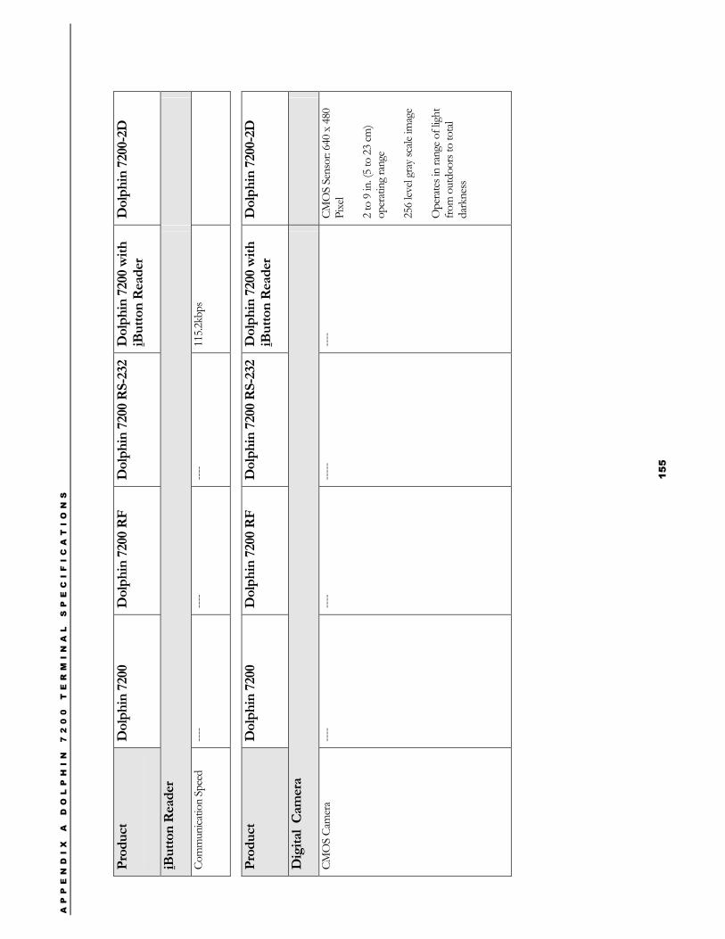
AP
PE
ND
IX
A
D
OL
PH
IN
7
20
0
TE
RM
IN
AL
S
PE
CI
FI
CA
TI
ON
S
15
5
Prod
uct
Dol
phin
720
0
Dol
phin
720
0 R
F D
olph
in 7
200
RS-
232
Dol
phin
720
0 w
ith
iBut
ton
Rea
der
Dol
phin
720
0-2D
iBut
ton
Rea
der
Com
mun
icatio
n Sp
eed
----
----
----
115.2
kbps
Pr
oduc
t D
olph
in 7
200
D
olph
in 7
200
RF
Dol
phin
720
0 R
S-23
2 D
olph
in 7
200
with
iB
utto
n R
eade
r D
olph
in 7
200-
2D
Dig
ital
Cam
era
CMO
S Ca
mer
a ---
- ---
- ---
-- ---
- CM
OS
Sens
or: 6
40 x
480
Pi
xel
2 to
9 in
. (5
to 2
3 cm
) op
erat
ing
rang
e
256
level
gray
scale
imag
e
Ope
rate
s in
rang
e of l
ight
from
out
door
s to
tota
l da
rkne
ss
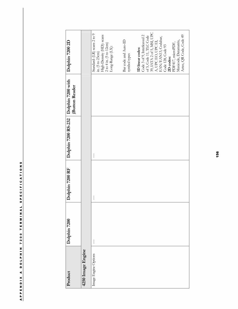
AP
PE
ND
IX
A
D
OL
PH
IN
7
20
0
TE
RM
IN
AL
S
PE
CI
FI
CA
TI
ON
S
15
6
Pr
oduc
t D
olph
in 7
200
D
olph
in 7
200
RF
Dol
phin
720
0 R
S-23
2 D
olph
in 7
200
with
iB
utto
n R
eade
r D
olph
in 7
200
2D
4250
Imag
e E
ngin
e
Imag
e Eng
ine O
ptio
ns
----
----
----
St
anda
rd: (
LR) s
cans
2 to
9
in. (
5 to
23c
m)
High
-Den
sity (
HD
): sc
ans
2 to
4 in
. (5
to 1
2cm
) Lo
ng-R
ange
(LX
):
Bar c
ode a
nd A
uto-
ID
sym
bol t
ypes
1D
line
ar c
odes
: Co
de 3
of 9
, Int
erlea
ved
2 of
5, C
ode 1
1, TL
C Co
de
39, I
ATA
2 o
f 5, M
SI, U
PC
A, U
PC E
O, U
PC E
I, EA
N/E
AN
13, C
odab
ar,
Code
128
, Cod
e 93
2D c
odes
: PD
F417
, micr
oPD
F,
Max
icode
, Dat
amat
rix,
Azt
ec, Q
R Co
de, C
ode 4
9
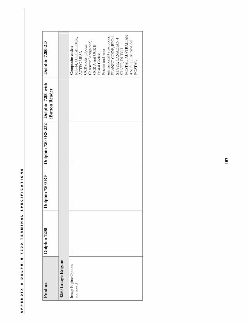
AP
PE
ND
IX
A
D
OL
PH
IN
7
20
0
TE
RM
IN
AL
S
PE
CI
FI
CA
TI
ON
S
15
7
Pr
oduc
t D
olph
in 7
200
D
olph
in 7
200
RF
Dol
phin
720
0 R
S-23
2 D
olph
in 7
200
with
iB
utto
n R
eade
r D
olph
in 7
200-
2D
4250
Imag
e E
ngin
e
Imag
e Eng
ine O
ptio
ns
cont
inue
d ---
--
----
----
----
Com
posit
e co
des:
RSS-
14, C
OD
ABL
OCK
, A
ZTEC
MES
A
OCR
code
s (O
ptica
l Ch
arac
ter R
ecog
nitio
n):
OCR
A an
d O
CR B
Po
stal
Cod
es:
Postn
et an
d m
ost
inte
rnat
iona
l 4 st
ate c
odes
, PL
AN
ET C
OD
E, B
PO 4
ST
ATE
, CA
NA
DIA
N 4
ST
ATE
, DU
TCH
PO
STA
L, A
UST
RALI
AN
4
STA
TE, J
APA
NES
E PO
STA
L
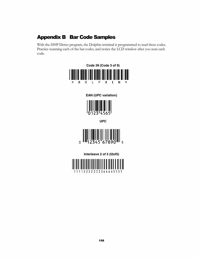
158
Appendix B Bar Code Samples With the HHP Demo program, the Dolphin terminal is programmed to read these codes. Practice scanning each of the bar codes, and notice the LCD window after you scan each code.
Code 39 (Code 3 of 9)
EAN (UPC variation)
UPC
Interleave 2 of 5 (I2of5)

159
Appendix C Dolphin 7200 2D Decoding Demo Menu Layout
The flow diagram above shows the layout of the menus available in the 2D Decoding Demo. Shown below are screen shots of the different menus listed above.
Example: Selecting ALD decoding mode.
Press F3 to get main menu screen
Press F3 to set a decoding option
Press F1 to select the desired decoding mode
Press F3 to select ALD Mode
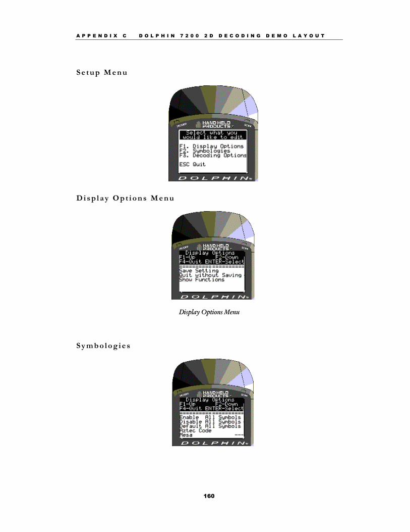
A P P E N D I X C D O L P H I N 7 2 0 0 2 D D E C O D I N G D E M O L A Y O U T
160
S e t u p M e n u
D i s p l a y O p t i o n s M e n u
Display Options Menu
S y m b o l o g i e s
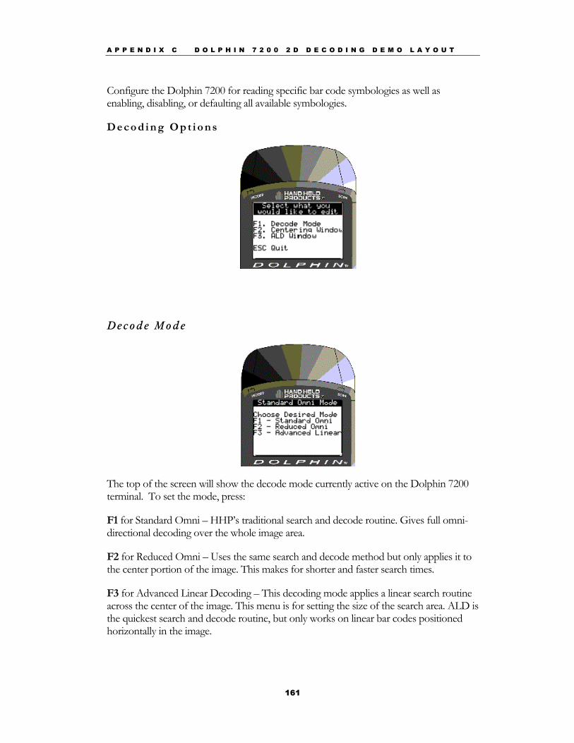
A P P E N D I X C D O L P H I N 7 2 0 0 2 D D E C O D I N G D E M O L A Y O U T
161
Configure the Dolphin 7200 for reading specific bar code symbologies as well as enabling, disabling, or defaulting all available symbologies.
D e c o d i n g O p t i o n s
Decode M o de
The top of the screen will show the decode mode currently active on the Dolphin 7200 terminal. To set the mode, press:
F1 for Standard Omni – HHP’s traditional search and decode routine. Gives full omni-directional decoding over the whole image area.
F2 for Reduced Omni – Uses the same search and decode method but only applies it to the center portion of the image. This makes for shorter and faster search times.
F3 for Advanced Linear Decoding – This decoding mode applies a linear search routine across the center of the image. This menu is for setting the size of the search area. ALD is the quickest search and decode routine, but only works on linear bar codes positioned horizontally in the image.
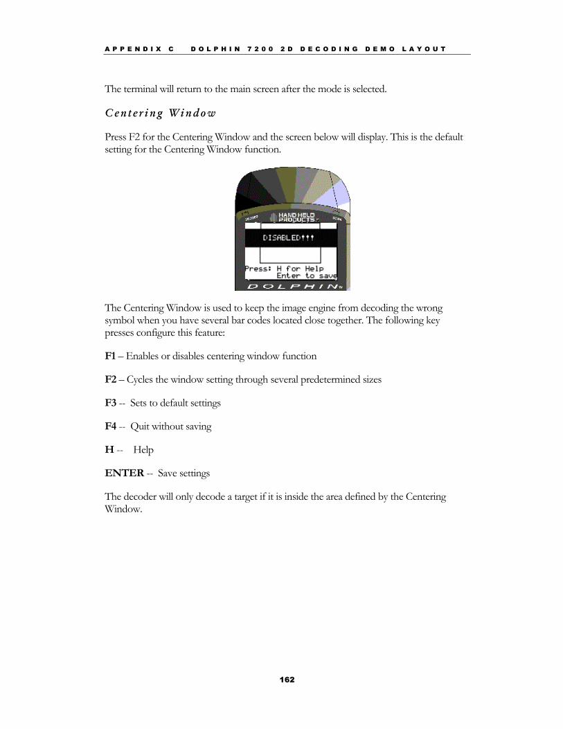
A P P E N D I X C D O L P H I N 7 2 0 0 2 D D E C O D I N G D E M O L A Y O U T
162
The terminal will return to the main screen after the mode is selected.
C ente r ing W indow
Press F2 for the Centering Window and the screen below will display. This is the default setting for the Centering Window function.
The Centering Window is used to keep the image engine from decoding the wrong symbol when you have several bar codes located close together. The following key presses configure this feature:
F1 – Enables or disables centering window function
F2 – Cycles the window setting through several predetermined sizes
F3 -- Sets to default settings
F4 -- Quit without saving
H -- Help
ENTER -- Save settings
The decoder will only decode a target if it is inside the area defined by the Centering Window.
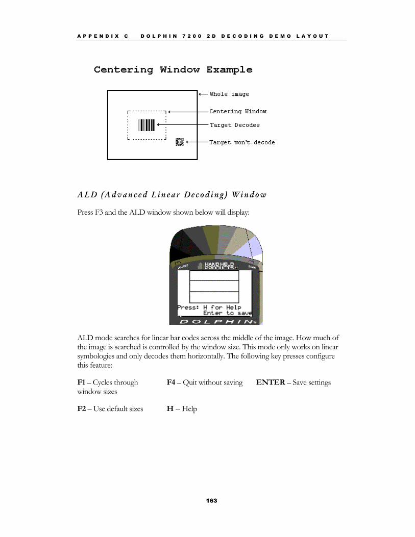
A P P E N D I X C D O L P H I N 7 2 0 0 2 D D E C O D I N G D E M O L A Y O U T
163
A L D (A dva nced L inea r Decod ing ) W indow
Press F3 and the ALD window shown below will display:
ALD mode searches for linear bar codes across the middle of the image. How much of the image is searched is controlled by the window size. This mode only works on linear symbologies and only decodes them horizontally. The following key presses configure this feature:
F1 – Cycles through window sizes
F4 – Quit without saving ENTER – Save settings
F2 – Use default sizes H -- Help
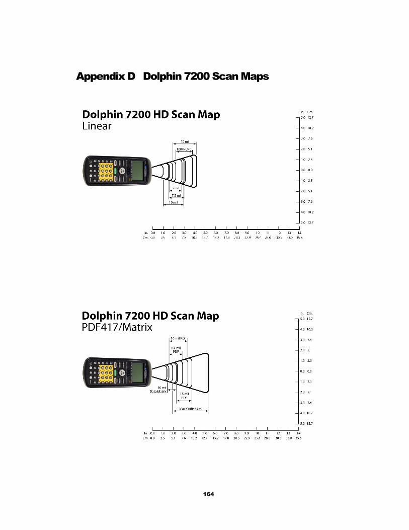
164
Appendix D Dolphin 7200 Scan Maps
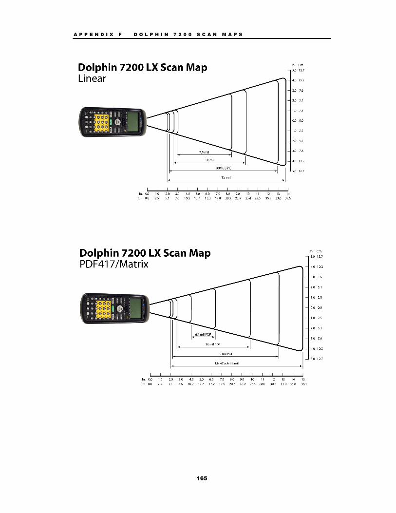
A P P E N D I X F D O L P H I N 7 2 0 0 S C A N M A P S
165
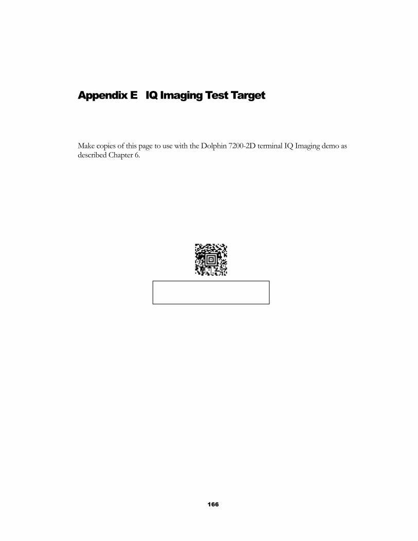
166
Appendix E IQ Imaging Test Target
Make copies of this page to use with the Dolphin 7200-2D terminal IQ Imaging demo as described Chapter 6.

167
Appendix F GS-DOS Commands The Dolphin terminal ships with General Software DOS (GS-DOS). GS-DOS is compatible with Microsoft DOS (MS-DOS) and is optimized to run in a very small amount of memory.
The following is a list of internal commands supported by GS-DOS:
HELP BREAK CALL
CD (CHDIR) CLS COPY
CTTY DATE DEL (ERASE)
DELAY DIR ECHO
EXIT FOR GOTO
IFMD (MKDIR) PATH PAUSE
PROMPT RD (RMDIR) REM
REBOOT REN SHIFT
SET SWITCH SYNC
TIME TRUENAME TYPE
VER VERIFY VOL
The following section describe the internal GS DOS commands in detail.
Warning: The command line functions are intended for developers only. Some commands may produce undesirable results or may not function at all. In addition, the LCD may not display the command results properly.

A P P E N D I X F G S D O S C O M M A N D S
168
HELP
The HELP command displays a list of the commands that are supported by the command interpreter.
Syntax: HELP
BREAK
The BREAK command changes or displays how GS DOS handles break-ins by the user with ^C and CTL-BRK key sequences. If BREAK is ON, then GS DOS will break out of a running program or batch file when the ^C or CTL-BRK keys are pressed. If BREAK is OFF, then GS DOS will not break out, but will instead pass the keys pressed to the program.
Syntax: BREAK [ONlOFF]
CALL
The CALL command executes a pre-recorded list of commands as a subroutine.
Syntax: Call [d:] [pathname] [parameter1] [parameter2] [… ]
CD (CHDIR)
The CD command displays the current directory of the specified drive, or can change the current directory of the specified drive. If no drive is specified, then the default drive is used.
Syntax: CD [drive:][pathname]
CLS
The CLS command clears the terminal's screen and resets the cursor position to the upper-left hand corner of the screen. The next prompt is issued on the top line of the screen.
Syntax: CLS
COPY
The COPY command copies one or more files to a new destination. If the destination path names a file, then all of the source files are written to the target file, concatenated together.
Syntax: COPY [drive:]pathname [drive:]pathname
A P P E N D I X F G S D O S C O M M A N D S
169
CTTY
The CTTY command changes the default console device
Syntax: CTTY device
Note: This command is not supported the Dolphin Terminal.
DATE
The DATE command displays the current date (month, day, date, and year) on the screen. If a user specifies a new date on the command line, then DATE will change the date to the one specified. This command updates the battery-maintained clock so that the new date will be remembered across power-downs.
Syntax: DATE [mon-dd-yyyy]
DEL (ERASE or ERA)
The DEL command deletes one or more files from a file system on a specific drive. If the specified path is a directory, all files in that directory will be deleted. If the path contains wildcards, then all files that match the wildcard specification will be deleted.
Syntax: DEL [drive:]pathname
DELAY
The DELAY command delays a batch file for a specified amount of time.
Syntax: DELAY seconds
DIR
The DIR command displays the files and sub-directories in a directory on the specified drive. If the drive is not specified, then the default drive is assumed. DIR uses the path operand to determine which files to list. If the path is not specified, then the current directory is assumed. If the specified path is a directory name, then all files in that directory are listed. If the specified path is a wildcard filename, then all files matching the path specification are listed.
Syntax: DIR [drive:][path] [wildcard-filename]
A P P E N D I X F G S D O S C O M M A N D S
170
ECHO
The ECHO command has two functions; namely, control of the ECHO flag, and displaying messages in batch files. ECHO mode controls the command processor's echoing of commands in batch files. If ECHO mode is on, then commands read from batch files are automatically echoed to the screen before they are executed. If ECHO mode is off, then commands are not echoed as they are executed. To display the current ECHO flag status, use the ECHO command without any parameters. To display a message from a batch file, use the ECHO command with a non-empty string to be displayed. The special form of the ECHO command with a period (“.”) immediately following the word ECHO (no intervening space) causes a blank line to be echoed.
Syntax: ECHO [ONlOFFlstring]
EXIT
The EXIT command terminates the current command shell and reverts control to the previous shell, provided that the current command shell is not the first one loaded in the system. The very first shell cannot be terminated with EXIT. If executed from a batch file, EXIT will terminate the batch file in a controlled manner causing control to be transferred to the keyboard user.
Syntax: EXIT
GOTO
The GOTO command causes the command processor to start executing commands that follow the specified label, in the current batch file. Labels can be inserted anywhere in batch files, and take the following form: “: label”.
Syntax: GOTO label
IF
The IF command causes a command to be executed if (or if NOT) a condition is TRUE.
Syntax: IF [NOT] ERRORLEVEL n statement
IF [NOT] EXIST filename statement
A P P E N D I X F G S D O S C O M M A N D S
171
MD (MKDIR)
The MD command creates a subdirectory in the root directory or a subdirectory. By using the MKDIR command, tree-structured file systems can be created. If a drive is specified, then the directory is created on the specified drive. Otherwise, it is created on the default drive.
Syntax: MD [drive:]path
PATH
The PATH command displays or changes the current search path that is used by the command processor, COMMAND.COM, to locate user programs and batch files. If no pathlist parameter is specified, then the current path is displayed. If a pathlist parameter is specified, then the path will be changed to the one specified.
Syntax: PATH [pathl[;path2][;path3][;...]
PAUSE
The PAUSE command is typically used in batch files to suspend execution of the batch file, print a message on the screen, and wait for the user to press a key after some action has been performed. PAUSE displays the following message on the screen before accepting a keypress from the user, “Strike any key when ready”.
Syntax: PAUSE
PROMPT
The PROMPT command maintains the PROMPT environment variable that is used by COMMAND.COM to display something before the user is asked to type-in a command.
The default PROMPT variable is $n$g. This has the effect of showing the current drive letter followed by a "greater-than" sign:
Syntax: PROMPT string
A P P E N D I X F G S D O S C O M M A N D S
172
RD (RMDIR)
The RD command removes a subdirectory from a root directory or of a subdirectory. This command can only be used to delete directories, and cannot be used to delete files, even if they are inside the directory to be removed. Conversely, the DEL command cannot delete directories; only the files they contain. If a drive is specified, then the directory on the specified drive is removed. Otherwise, the default drive is assumed.
Syntax: RD [drive:]path
REM
The REM command provides a simple way of entering a free-form comment in a batch file. The line starting with REM has no effect on the execution of the batch file.
Syntax: REM any comment
REBOOT
The REBOOT command will reset the terminal.
Syntax: REBOOT
REN
The REN command renames a file or group of files. Files cannot be moved in the directory structure with this command; instead, only their filenames are altered within the directory in which they reside. Wildcards may be used in the second pathname to indicate that the characters in that component of the first filename are to be kept as-is.
Syntax: REN [drive:][path]filespec filespec
A P P E N D I X F G S D O S C O M M A N D S
173
SHIFT
The SHIFT command allows access to multiple batch file arguments. The command shifts the contents of the 9 batch file arguments so that %2 is copies into %1, %3 is copies into %2 and so on.
Syntax: SHIFT
SET
The SET command displays the entire environment space (one variable per line), or changes the assignment of one variable in the environment space. If no operands are specified, then the SET command simply displays all of the environment variables in the environment space. If a variable name and an equal sign is given, but no string is specified, then the variable name is removed from the environment space. If the string is specified, then the previous definition of the variable is deleted, and the new one is installed in the environment.
Syntax: SET [keyword=[string]]
SHIFT
Displays or changes the optional switch character.
Syntax: SWITCH [character]
A P P E N D I X F G S D O S C O M M A N D S
174
SYNC
The SYNC command provides a synchronization checkpoint feature that enables a batch file to flush the file system's buffers to disk before doing something that might otherwise cause a disorderly shutdown
Syntax: SYNC
TIME
The TIME command displays or changes the system time. If no parameter is specified, then the current system time is displayed, and the user is queried for the new system time. If the user just presses the ENTER key, the system time is not changed. If the user enters a new time, then the system's real-time-clock is updated.
Syntax: TIME [hh:mm:ss[.hh]]
TRUENAME
The TRUENAME command displays the true name and path of a file.
Syntax: TRUENAME file
TYPE
The TYPE command copies the contents of the specified file to standard output (usually, the screen). If the drive letter is not specified, then the default drive is assumed.
Syntax: TYPE [drive:][path]filespec
VER
The VER command displays the MS-DOS emulation version number, as well as the version of the Embedded DOS-ROM operating system that is running.
Syntax: VER
VERIFY
A P P E N D I X F G S D O S C O M M A N D S
175
The VERIFY command changes or displays how GS DOS handles I/O to disk files and directory structures. If VERIFY is ON, then Embedded DOS-ROM verifies immediately that disk I/O is completed successfully before telling the user that it was. This is accomplished by writing data directly to disk, without temporarily storing it in a file system or disk driver cache. If VERIFY is OFF, then GS DOS caches writes to files and defers the actual writing to disk, enabling multiple writes to the same sectors to be served much faster. The cache is automatically written to disk in the background during "dead time", when the disk is not busy. This is accomplished with the multitasking threads and semaphores that the GS DOS kernel supports.
Syntax: VERIFY [ONIOFF]
VOL
The VOL command displays the volume label of a diskette or a hard disk. VOL does not allow the user to change the volume label. If the drive letter is not specified, then the default drive is assumed.
Syntax: VOL [drive:]
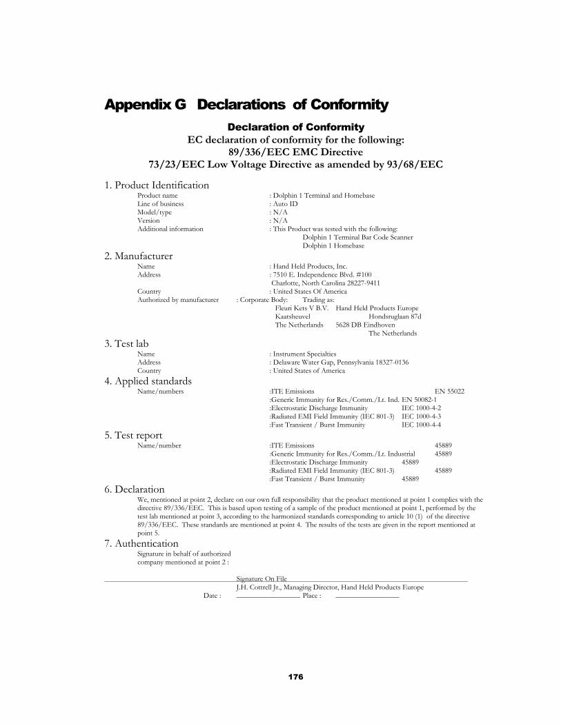
176
Appendix G Declarations of Conformity Declaration of Conformity
EC declaration of conformity for the following: 89/336/EEC EMC Directive
73/23/EEC Low Voltage Directive as amended by 93/68/EEC 1. Product Identification Product name : Dolphin 1 Terminal and Homebase Line of business : Auto ID Model/type : N/A Version : N/A Additional information : This Product was tested with the following: Dolphin 1 Terminal Bar Code Scanner Dolphin 1 Homebase 2. Manufacturer Name : Hand Held Products, Inc. Address : 7510 E. Independence Blvd. #100 Charlotte, North Carolina 28227-9411 Country : United States Of America Authorized by manufacturer : Corporate Body: Trading as: Fleuri Kets V B.V. Hand Held Products Europe Kaatsheuvel Hondsruglaan 87d The Netherlands 5628 DB Eindhoven The Netherlands 3. Test lab Name : Instrument Specialties Address : Delaware Water Gap, Pennsylvania 18327-0136 Country : United States of America 4. Applied standards Name/numbers :ITE Emissions EN 55022 :Generic Immunity for Res./Comm./Lt. Ind. EN 50082-1 :Electrostatic Discharge Immunity IEC 1000-4-2 :Radiated EMI Field Immunity (IEC 801-3) IEC 1000-4-3 :Fast Transient / Burst Immunity IEC 1000-4-4 5. Test report Name/number :ITE Emissions 45889 :Generic Immunity for Res./Comm./Lt. Industrial 45889 :Electrostatic Discharge Immunity 45889 :Radiated EMI Field Immunity (IEC 801-3) 45889 :Fast Transient / Burst Immunity 45889 6. Declaration We, mentioned at point 2, declare on our own full responsibility that the product mentioned at point 1 complies with the
directive 89/336/EEC. This is based upon testing of a sample of the product mentioned at point 1, performed by the test lab mentioned at point 3, according to the harmonized standards corresponding to article 10 (1) of the directive 89/336/EEC. These standards are mentioned at point 4. The results of the tests are given in the report mentioned at point 5.
7. Authentication Signature in behalf of authorized company mentioned at point 2 : Signature On File J.H. Cottrell Jr., Managing Director, Hand Held Products Europe Date : _________________ Place : _________________

177
Declaration of Conformity EC declaration of conformity for the following:
89/336/EEC EMC Directive 73/23/EEC Low Voltage Directive as amended by 93/68/EEC
1. Product Identification
Product Name : Dolphin RF 2.4 GHz Portable Data Collection Terminal Line of Business : Auto ID Model/Type : N/A Version : N/A Additional Information : This product was tested with the following: Dolphin I Homebase.
2. Manufacturer Name : Hand Held Products. Inc. Address : 7510 East Independence Blvd. Charlotte, North Carolina 28227-9411 Country : United States of America Authorized by Manufacturer : Corporate Body: Trading As:
Fleuri Kets V B.V. Hand Held Products Europe Kaatsheuvel Hondsruglaan 87d The Netherlands 5628 DB Eindhoven The Netherlands
3. Test Labs Name : Teleficaton BV Address : Utrechtseweg 310 Country : The Netherlands Name : SGS US Testing Company Inc Address : 291 Fairfield Avenue Country : Fairfield, NJ 07004 USA
4. Applied Standards
Name/Numbers : ITE Emissions EN 55022:1995 : Electromagnetic Immunity for Res,/Comm./Lt. Industrial ETS 300 826:1997 Including: : Electrostatic Discharge Immunity EN 61000-4-2:1995
: Radiated EMI Field Immunity EN 61000-4-3:1996 : Fast Transient / Burst Immunity EN 61000-4-4:1995 : Conducted RF Immunity EN 61000-4-6:1996 : Safety of Information Technology Equipment, Including Electrical Business Equipment (LVD) EN 60950:1992
Page 1 of 2 Revision C
178
Declaration of Conformity EC declaration of conformity for the following:
89/336/EEC EMC Directive 73/23/EEC Low Voltage Directive as amended by 93/68/EEC
5. Test Report
Name/Number : Telefication : ITE Emissions 98302120
: Electromagnetic Immunity for Res./ Comm,/Lt. Ind. (as listed above): 98302120 : SGS
: LVD Compliance U0212
6. Type Approval Certifications Country/Approval Number
: FCC/USA : HD5RFDolphin-1 : Canada : 16931021078A : Netherlands, UK, Austria : NL98062970 : Germany : D800372K : Switzerland : 98.0517.L.P : Denmark : CEPT/RLAN/DK/9817 : Norway : CEPT/RLAN N NO98000529-R : Sweden : Ue980117 : Belgium : RTT/RL/X070 : Italy : DGPGF/4/2/334473/2590/061098 : Hungary : 1705-2/99 : Greece : CEPT-RLAN-GR.YME TA 164 : Ireland : IRL TRA 24/5/242/1 : Spain : E/D.G.Tel./08/99/0221 : France : 980321PPO
7. Declaration
We, mentioned at point 2, declare on our own full responsibility that the product mentioned at point 1 complies with the directive 89/336/EEC and 73/23/EEC as amended by 93/68/EEC. This based upon testing of a sample of the product mentioned at point 1, performed by the test labs mentioned at point 3, according to the harmonized standards corresponding to article 10 (1) of the directive 89/336/EEC and to 73/23/EEC as amended by 93/68/EEC. These standards are mentioned at point 4. The results of the tests are given in the reports mentioned at point 5.
8. Authentication Signature on behalf of authorized Company mentioned at point 2:
Signature on file J.H. Cottrell Jr., Managing Director, Hand Held Products, Europe Date : October 27th , 1998 Place: North Carolina, USA
Page 2 of 2 Revision C

179