Embed Size (px)
Citation preview

LNG as Fuel –
Bunkering, Storage and
Processing
STG International
Conference
“Ship Efficiency”
Hamburg,
26/27-September-2011
Carriers &
Offshore Units
Jürgen Harperscheidt
Sales Manager
CONTENT
TGE Company Profile
Small LNG carriers
Bunkering
LNG fuel tanks
LNG fuel gas systems
Conclusions
2
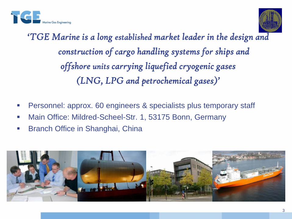
‘TGE Marine is a long established market leader in the design and
construction of cargo handling systems for ships and
offshore units carrying liquefied cryogenic gases
(LNG, LPG and petrochemical gases)’
Personnel: approx. 60 engineers & specialists plus temporary staff
Main Office: Mildred-Scheel-Str. 1, 53175 Bonn, Germany
Branch Office in Shanghai, China
3
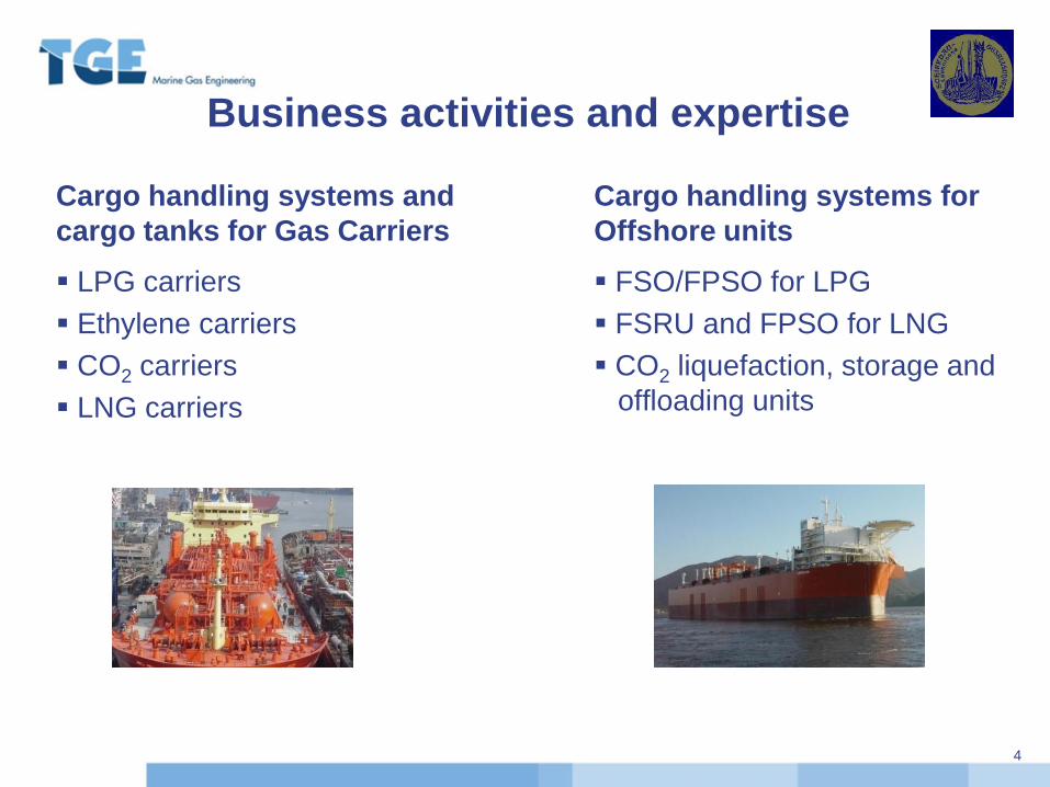
Business activities and expertise
Cargo handling systems and
cargo tanks for Gas Carriers
LPG carriers
Ethylene carriers
CO2 carriers
LNG carriers
Cargo handling systems for
Offshore units
FSO/FPSO for LPG
FSRU and FPSO for LNG
CO2 liquefaction, storage and
offloading units
4
5
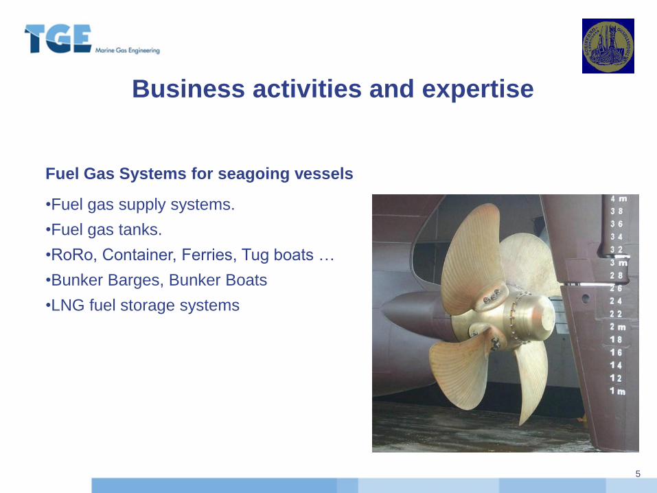
Fuel Gas Systems for seagoing vessels
•Fuel gas supply systems.
•Fuel gas tanks.
•RoRo, Container, Ferries, Tug boats …
•Bunker Barges, Bunker Boats
•LNG fuel storage systems
Business activities and expertise
CONTENT
TGE Company Profile
Small LNG carriers
Bunkering
LNG fuel tanks
LNG fuel gas systems
Conclusions
6
7
Upcoming regulation on SOx, NOx, PM and CO2 emissions require
adequate changes in ship propulsion. LNG as fuel is one solution to
cover all mentioned pollutants. The same is valid for energy supply in
some remote areas that could be done by LNG.
Available Infrastructure
Large scale terminals and shipping
Regional LNG distribution networks (Norway)
Few number of small LNG Carriers
Missing Infrastructure
Satellite terminals close to bunkering locations
LNG feeder ships with sufficient capacity
Bunker ships/barges/vessels
Current Situation
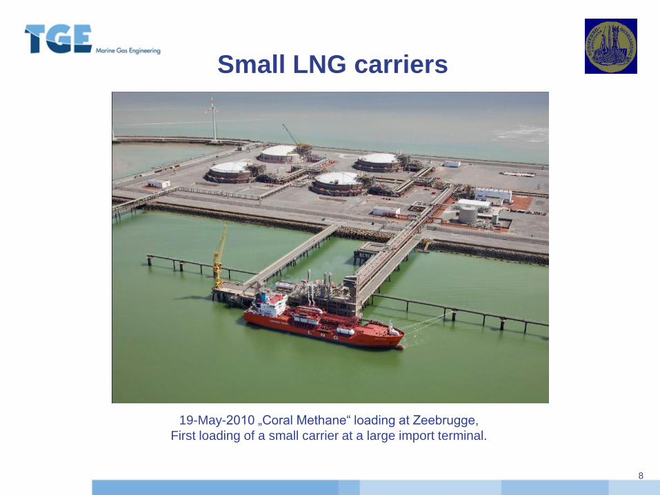
Small LNG carriers
19-May-2010 „Coral Methane“ loading at Zeebrugge,
First loading of a small carrier at a large import terminal.
8
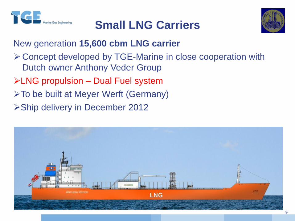
New generation 15,600 cbm LNG carrier
Concept developed by TGE-Marine in close cooperation with
Dutch owner Anthony Veder Group
LNG propulsion – Dual Fuel system
To be built at Meyer Werft (Germany)
Ship delivery in December 2012
Small LNG Carriers
9
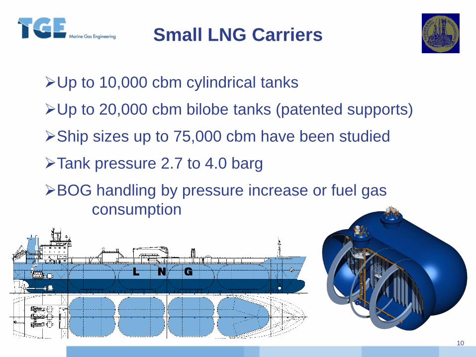
Up to 10,000 cbm cylindrical tanks
Up to 20,000 cbm bilobe tanks (patented supports)
Ship sizes up to 75,000 cbm have been studied
Tank pressure 2.7 to 4.0 barg
BOG handling by pressure increase or fuel gas
consumption
Small LNG Carriers
10
CONTENT
TGE Company Profile
Small LNG carriers
Bunkering
LNG fuel tanks
LNG fuel gas systems
Conclusions
11
Bunkering
Requirements for future operations:
• High loading rates due to tight time schedule
• Large total amount of LNG for larger vessels
• Safe but easy handling of heavy equipment
• Dry-break emergency couplings
• Bunkering during cargo operations
• data/ESD connection
• avoid spool pieces/reducers
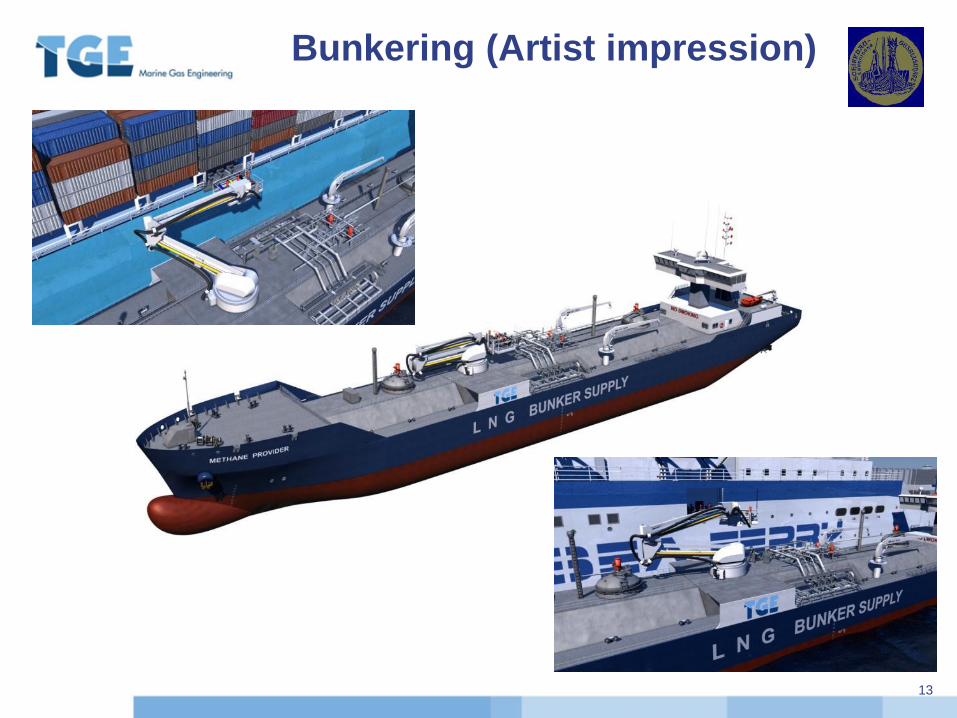
This will only be possible with bunker vessels (small
LNG carriers as above) coming alongside
Regulations and standards for the bunker interface
and related operations are under preparation by
several international working groups
12
13
Bunkering (Artist impression)
CONTENT
TGE Company Profile
Small LNG carriers
Bunkering
LNG fuel tanks
LNG fuel gas systems
Conclusions
14
15
LNG fuel tanks
All independent types (A, B and C acc. to IMO IGC)
possible following IGF guideline. BLG 15 also
deleted restriction on membrane tanks
Type A and B and membrane with low pressure,
therefore BOG problem to be solved
Secondary Barrier required for membrane as well
as type A and B tanks
Type C preferred solution due to high design
pressure 4 to 10 barg
High operation flexibility regarding loading and
BOG pressure increase
Disadvantages: Tank shape resulting in bad volume
efficiency (factor 3 to 4), filling limits
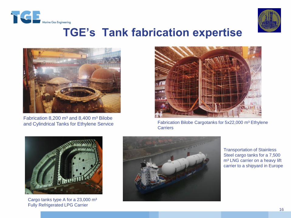
TGE’s Tank fabrication expertise
Fabrication 8,200 m³ and 8,400 m³ Bilobe
and Cylindrical Tanks for Ethylene Service Fabrication Bilobe Cargotanks for 5x22,000 m³ Ethylene
Carriers
Cargo tanks type A for a 23,000 m³
Fully Refrigerated LPG Carrier
Transportation of Stainless
Steel cargo tanks for a 7,500
m³ LNG carrier on a heavy lift
carrier to a shipyard in Europe
16
Tank Insulation
Vacuum insulation for small cylindrical tanks
PS or PU preformed slabs covered by steel sheets,
allow for conical and bilobe shapes
PU foam covered by polymeric protection layer
Special panels for increased insulation efficiency
Choice depending on requirements
(operation/consumption schedule, possible tank
shape)
17
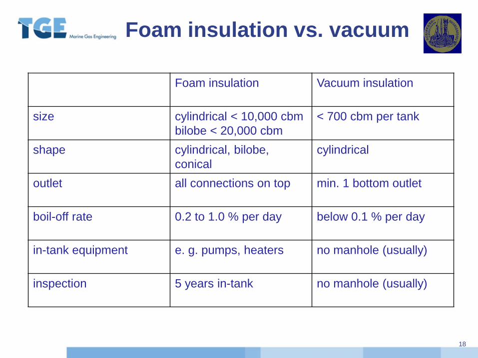
18
Foam insulation Vacuum insulation
size cylindrical < 10,000 cbm
bilobe < 20,000 cbm
< 700 cbm per tank
shape cylindrical, bilobe,
conical
cylindrical
outlet all connections on top min. 1 bottom outlet
boil-off rate 0.2 to 1.0 % per day below 0.1 % per day
in-tank equipment e. g. pumps, heaters no manhole (usually)
inspection 5 years in-tank no manhole (usually)
Foam insulation vs. vacuum
CONTENT
TGE Company Profile
Small LNG carriers
Bunkering
LNG fuel tanks
LNG fuel gas systems
Conclusions
19
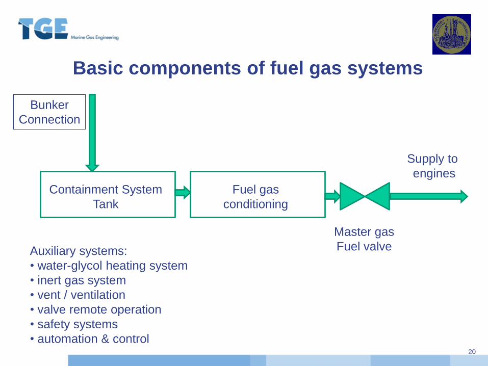
Basic components of fuel gas systems
Containment System
Tank
Bunker
Connection
Supply to
engines
Master gas
Fuel valve
Fuel gas
conditioning
Auxiliary systems:
• water-glycol heating system
• inert gas system
• vent / ventilation
• valve remote operation
• safety systems
• automation & control
20
21
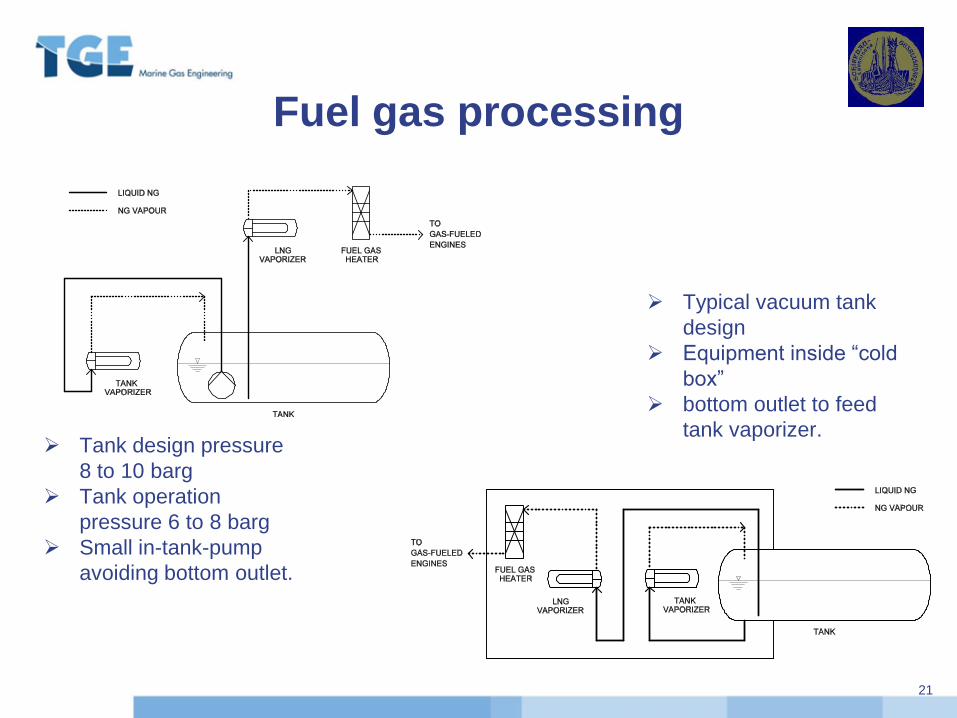
Fuel gas processing
Tank design pressure
8 to 10 barg
Tank operation
pressure 6 to 8 barg
Small in-tank-pump
avoiding bottom outlet.
Typical vacuum tank
design
Equipment inside “cold
box”
bottom outlet to feed
tank vaporizer.
22
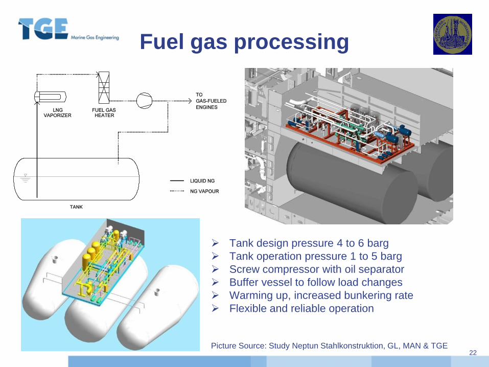
Fuel gas processing
Tank design pressure 4 to 6 barg
Tank operation pressure 1 to 5 barg
Screw compressor with oil separator
Buffer vessel to follow load changes
Warming up, increased bunkering rate
Flexible and reliable operation
Picture Source: Study Neptun Stahlkonstruktion, GL, MAN & TGE
23
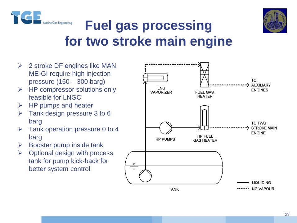
Fuel gas processing
for two stroke main engine
2 stroke DF engines like MAN
ME-GI require high injection
pressure (150 – 300 barg)
HP compressor solutions only
feasible for LNGC
HP pumps and heater
Tank design pressure 3 to 6
barg
Tank operation pressure 0 to 4
barg
Booster pump inside tank
Optional design with process
tank for pump kick-back for
better system control
CONTENT
TGE Company Profile
Small LNG carriers
Bunkering
LNG fuel tanks
LNG fuel gas systems
Conclusions
24
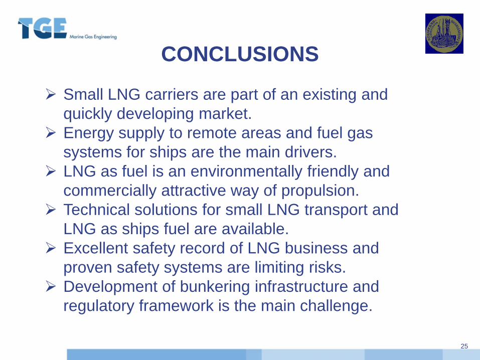
CONCLUSIONS
Small LNG carriers are part of an existing and
quickly developing market.
Energy supply to remote areas and fuel gas
systems for ships are the main drivers.
LNG as fuel is an environmentally friendly and
commercially attractive way of propulsion.
Technical solutions for small LNG transport and
LNG as ships fuel are available.
Excellent safety record of LNG business and
proven safety systems are limiting risks.
Development of bunkering infrastructure and
regulatory framework is the main challenge.
25


![VALVES & CONTROLS...Differential pressure across the valve, equal to absolute pressure inside the pressure vessel minus atmospheric pressure (14.7 psi [1.01 barg] at sea level). Relief](https://img.dokumen.tips/doc/110x75/5e95fe0610fc8f6072670ecc/valves-controls-differential-pressure-across-the-valve-equal-to-absolute.jpg)


![¹´탈로그] 25P... · DN150 25P 0.2 2.1 barg 1.4 7.0 barg 5.6 14.0 barg (25PE : 5.6 14 barg, 2000 ASTM A126 B ASTM A216](https://img.dokumen.tips/doc/110x75/5b6b34307f8b9a422e8d214f/-25p-dn150-25p-02-21-barg-14-70-barg-56-140-barg-25pe.jpg)