Embed Size (px)
Citation preview
HALFEN HTA, HTA-CE, HZA, HZA Dynagrip INST_HTA 03/15
Assembly Instructions • Montageanleitung • Montagehandleiding • Instrukcja montażu • Montážní návod
Cast-in channelsHalfenschienenHalfenrailKotwy szynoweProfi ly Halfen

Čes
ky
General Certifi cates of Approval by DIBt Berlin:
HALFEN Cast-in channels HTA and HZA
2.1
1.1
1.2 Note: The HTA-CE channels also fulfi l all the requirements stipulated in the German Approval No. Z-21.4-34 for HTA channels and can therefore be used accor-dingly.
Type identifi cation: on the inside of the profi le back. Additionally on the side of the profi le (partly for
types with Combi Strip Filler).
Select HALFEN Cast-in channel acc. to the design documents.
HTA HZA HZADYNAGRIP41/22
Z-21.4-34 Z-21.4-145 Z-21.4-1691
Anchor
Nailing hole
Combi strip fi ller
HALFEN Cast-in channels HTA-CE
Dimensioning acc. to CEN/TS 1992-4: 2009 applying to European Technical Approval ETA-09/0339
HALFEN Channels are supplied with a Combi strip fi ller and with punched holes for nailing to the formwork. Possibly overlapping Combi strip fi ller has to be cut fl ush at the channel end. When fi xing to the formwork, make sure that the type of HALFEN Channel (profi le, material, length) and its position is in accordance with the drawing. Fix channels securely so that they will not be displaced during the pou-ring of the concrete and remain fl ush with the surface of the formwork. If no formwork is available to nail, choose other fi xing method.
432-CPD-8394-01
2. Preparations
1. Type identifi cation/ General information
!
To avoid any rust contamination on stainless steel HALFEN Channels: Remove steel packing ribbons immediately. Store separately with suffi cient distance to other metals. Avoid damage of surface and contami-nation due to contact with carbon steel. Dry, roofed and well ventilated storage is recom-mended.
2.1
© 2015 HALFEN · INST_HTA 03/15 · www.halfen.com2
HALFEN HTA, HTA-CE, HZA, HZA Dynagrip Assembly InstructionsD
euts
chEn
glis
hN
eder
land
sPo
lski

Čes
ky
25 mm 25mm
3.1
≤200(250)mm ≤200(250)mm ≤200(250)mm
25 mm
3.2
25-35 mm
≤200(250)mm
MD
[mm]
3.3.1
3.3
3.3.3
3.3.2
3. HALFEN Channels - short lengths and channels cut to length
3.1
3.2
3.3
3.3.1
3.3.2
3.3.3
A range of diff erent short lengths is supplied.
HALFEN Channels can also be cut to length on site. At both ends of the cut piece a projection of 25 - 35 mm must remain between the fi rst/last an-chor and the end of the channel piece. HALFEN Channels must have at least 2 anchors.
HALFEN Cast-in channels with site applied end anchorsANK-E End anchors are offi cially approved under approval no. Z-21.4-34 DIBt Germany. They are not part of the European Technical Approval ETA-09/0339. ANK-E are not included in the delivery of HALFEN Channels. Please order separately in same material and fi nish as HALFEN channel.
Cut the HALFEN Channel as required. The cut section must be perpendicular to the channel axis. Maximum and minimum projections ”e” at the ends of HALFEN Channel are 175/225 and 35 mm.
Select the type of ANK-E End anchor to fi t to the HALFEN Channel according table below. Push the clamping element on the channel back until it comes to full stop; press in the foam fi ller when necessary.
Pull tight the hex head bolt to the torque indicated in the table below.
≥ 2 anchors!
≥ 2 anchors!
35 ≤ e ≤ 175(225)
35 ≤ e ≤ 175(225)
Site-applied HALFEN ANK-E End Anchor
Requested length, ready for use
175 mm for profi le 28/15, 38/17; 225 mm for profi le 40/22, 40/25 und 41/22
End Anchor selection
Short lengths HZA 41/22 may only be used with not more than 1 end anchor. Not part of the General Certifi cate of Approval No. Z-21.4-145.
HALFEN Channel End anchor Thread Tightening torque Tinst [Nm]
HTA 28/15 ANK - E1 M 8 10
HTA 38/17 ANK - E2 M 10 20
HTA 40/22 ANK - E2 M 10 20
HTA 40/25 ANK - E2 M 10 20
HZA 41/22 ANK - E2 M 10 20
© 2015 HALFEN · INST_HTA 03/15 · www.halfen.com 3
HALFEN HTA, HTA-CE, HZA, HZA Dynagrip Assembly Instructions
Deu
tsch
Engl
ish
Ned
erla
nds
Pols
ki
Čes
ky
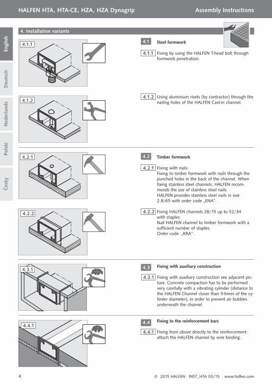
4. Installation variants
4.1.1 Fixing by using the HALFEN T-head bolt through formwork penetration.
4.1.2 Using aluminium rivets (by contractor) through the nailing holes of the HALFEN Cast-in channel.
4.2.1 Fixing with nails: Fixing to timber formwork with nails through the punched holes in the back of the channel. When fi xing stainless steel channels, HALFEN recom-mends the use of stainless steel nails. HALFEN provides stainless steel nails in size 2.8/65 with order code „ENA“.
Steel formwork
Timber formwork
4.2.2 Fixing HALFEN channels 28/15 up to 52/34 with staples: Nail HALFEN channel to timber formwork with a suffi cient number of staples. Order code: „KRA“.
4.3.1 Fixing with auxiliary construction see adjacent pic-ture. Concrete compaction has to be performed very carefully with a vibrating cylinder (distance to the HALFEN Channel closer than 5-times of the cy-linder diameter), in order to prevent air bubbles underneath the channel.
4.4.1 Fixing from above directly to the reinforcement:attach the HALFEN channel by wire binding.
Fixing with auxiliary construction
Fixing to the reinforcement bars
4.1.1
4.1.2
4.2.1
4.2.2
4.4.1
4.3.1
4.1
4.2
4.3
4.4
© 2015 HALFEN · INST_HTA 03/15 · www.halfen.com4
HALFEN HTA, HTA-CE, HZA, HZA Dynagrip Assembly InstructionsD
euts
chEn
glis
hN
eder
land
sPo
lski

Čes
ky
Accurate concrete compaction in the area of the HALFEN Channel is required!
Installation by placing the channel after casting in the wet concrete is not recommended! If this kind of installation cannot be avoided, very careful concrete compaction after placement of the channel is essential (minimum 10 seconds for short channels or 20 seconds per meter for long channels on either side with a vibrating cylinder or 10 seconds total with a vibrating table).
For appropriate application of HALFEN T-head bolts see bolt instructions HS/HSR/HZS!
Filling removal
Application of T-head bolts
4.4.2 Fixing from above to the reinforcement, using HALFEN ChanClip
Attach the HALFEN ChanClip to the HALFEN Channel, the ribbed pin of the ChanClip must be pushed into one of the nail holes in the HALFEN Channel. At least 2 ChanClips per channel are required.
Snap in auxiliary bars diam. 8 or 10 mm (rebars B500 B, by contractor) at the required position into the ChanClip. Apply the HALFEN Channel mounted with the ChanClip and the auxiliary bars to the reinforcement.
Check the appropriate height and attach the bars by wire binding.
HALFEN ChanClip
Catch the combi strip fi ller at one end and pull it out by hand with the simultaneously aid of a tool, e.g. screwdri-ver.
5. After concreting and striking the formwork
5.1
5.2
4.4.2
5.1
© 2015 HALFEN · INST_HTA 03/15 · www.halfen.com 5
HALFEN HTA, HTA-CE, HZA, HZA Dynagrip Assembly Instructions
Deu
tsch
Engl
ish
Ned
erla
nds
Pols
ki
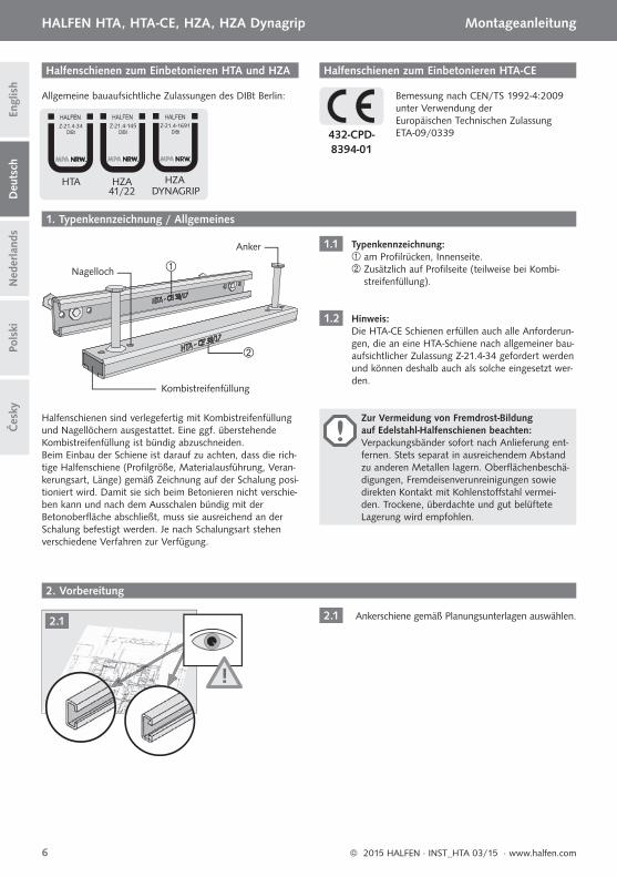
Allgemeine bauaufsichtliche Zulassungen des DIBt Berlin:
Halfenschienen zum Einbetonieren HTA und HZA
2.1
1.1
1.2
Typenkennzeichnung: am Profi lrücken, Innenseite. Zusätzlich auf Profi lseite (teilweise bei Kombi-
streifenfüllung).
Hinweis: Die HTA-CE Schienen erfüllen auch alle Anforderun-gen, die an eine HTA-Schiene nach allgemeiner bau-aufsichtlicher Zulassung Z-21.4-34 gefordert werden und können deshalb auch als solche eingesetzt wer-den.
Ankerschiene gemäß Planungsunterlagen auswählen.
HTA HZA HZADYNAGRIP41/22
Z-21.4-34 Z-21.4-145 Z-21.4-1691
Anker
Nagelloch
Kombistreifenfüllung
Halfenschienen zum Einbetonieren HTA-CE
Bemessung nach CEN/TS 1992-4:2009 unter Verwendung der Europäischen Technischen Zulassung ETA-09/0339
Halfenschienen sind verlegefertig mit Kombistreifenfüllung und Nagellöchern ausgestattet. Eine ggf. überstehende Kombistreifenfüllung ist bündig abzuschneiden. Beim Einbau der Schiene ist darauf zu achten, dass die rich-tige Halfenschiene (Profi lgröße, Materialausführung, Veran-kerungsart, Länge) gemäß Zeichnung auf der Schalung posi-tioniert wird. Damit sie sich beim Betonieren nicht verschie-ben kann und nach dem Ausschalen bündig mit der Betonoberfl äche abschließt, muss sie ausreichend an der Schalung befestigt werden. Je nach Schalungsart stehen verschiedene Verfahren zur Verfügung.
432-CPD-8394-01
2. Vorbereitung
1. Typenkennzeichnung / Allgemeines
!
Zur Vermeidung von Fremdrost-Bildung auf Edelstahl-Halfenschienen beachten: Verpackungsbänder sofort nach Anlieferung ent-fernen. Stets separat in ausreichendem Abstand zu anderen Metallen lagern. Oberfl ächenbeschä-digungen, Fremdeisenverunreinigungen sowie direkten Kontakt mit Kohlenstoff stahl vermei-den. Trockene, überdachte und gut belüftete Lagerung wird empfohlen.
2.1
© 2015 HALFEN · INST_HTA 03/15 · www.halfen.com6
HALFEN HTA, HTA-CE, HZA, HZA Dynagrip Montageanleitung Č
esky
Deu
tsch
Engl
ish
Ned
erla
nds
Pols
ki
25 mm 25mm
3.1
≤200(250)mm ≤200(250)mm ≤200(250)mm
25 mm
3.2
25-35 mm
≤200(250)mm
MD
[mm]
3.3.1
3.3
3.3.3
3.3.2
3. Halfenschienen - Kurzstücke und Zuschnitte nach Maß
3.1
3.2
3.3
3.3.1
3.3.2
3.3.3
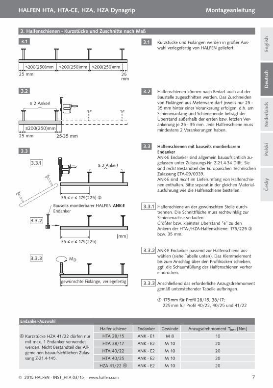
Kurzstücke und Fixlängen werden in großer Aus-wahl verlegefertig von HALFEN geliefert.
Halfenschienen können nach Bedarf auch auf der Baustelle zugeschnitten werden. Das Zuschneiden von Fixlängen aus Meterware darf jeweils nur 25 - 35 mm hinter einer Verankerung erfolgen, d.h. am Schienenanfang und Schienenende beträgt der Überstand außerhalb der ersten bzw. letzten Ver-ankerung je 25 - 35 mm. Jede Halfenschiene muss mindestens 2 Verankerungen haben.
Halfenschienen mit bauseits montierbarem EndankerANK-E Endanker sind allgemein bauaufsichtlich zu-gelassen unter Zulassungs-Nr. Z-21.4-34 DIBt. Sie sind nicht Bestandteil der Europäischen Technischen Zulassung ETA-09/0339. ANK-E sind nicht im Lieferumfang von Halfenschie-nen enthalten. Bitte separat in der gleichen Material-ausführung wie die Halfenschiene bestellen.
Halfenschiene an der gewünschten Stelle durch-trennen. Die Schnittfl äche muss rechtwinklig zur Schienenachse verlaufen. Größter bzw. kleinster Überstand ”e” zu den Ankern der HTA-/HZA-Halfenschiene: 175/225 bzw. 35 mm.
ANK-E Endanker passend zur Halfenschiene aus-wählen (siehe Tabelle unten). Das Klemmelement bis zum Anschlag über den Profi lrücken schieben, ggf. die Schaumfüllung der Halfenschienen vorher eindrücken.
Anschließend das erforderliche Anzugsdrehmoment gemäß untenstehender Tabelle aufbringen.
≥ 2 Anker!
≥ 2 Anker!
35 ≤ e ≤ 175(225)
35 ≤ e ≤ 175(225)
Bauseits montierbarer HALFEN ANK-E Endanker
gewünschte Fixlänge, verlegefertig
175 mm für Profi l 28/15, 38/17; 225 mm für Profi l 40/22, 40/25 und 41/22
Endanker-Auswahl
Kurzstücke HZA 41/22 dürfen nur mit max. 1 Endanker verwendet werden. Nicht Bestandteil der All-gemeinen bauaufsichtlichen Zulas-sung Z-21.4-145.
Halfenschiene Endanker Gewinde Anzugsdrehmoment Tinst [Nm]
HTA 28/15 ANK - E1 M 8 10
HTA 38/17 ANK - E2 M 10 20
HTA 40/22 ANK - E2 M 10 20
HTA 40/25 ANK - E2 M 10 20
HZA 41/22 ANK - E2 M 10 20
© 2015 HALFEN · INST_HTA 03/15 · www.halfen.com 7
HALFEN HTA, HTA-CE, HZA, HZA Dynagrip Montageanleitung
Čes
kyD
euts
chEn
glis
hN
eder
land
sPo
lski
4. Einbauvarianten
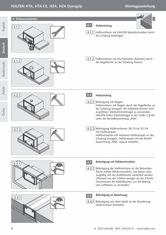
4.1.1 Halfenschiene mit HALFEN Spezialschrauben durch die Schalung befestigen.
4.1.2 Halfenschiene mit Alu-Popnieten (bauseits) durch die Nagellöcher an der Schalung fi xieren.
4.2.1 Befestigung mit Nägeln: Halfenschiene mit Nägeln durch die Nagellöcher an der Schalung annageln. Bei Edelstahlschienen wird empfohlen, Edelstahl-Drahtnägel zu verwenden. HALFEN liefert Edelstahlnägel in der Größe 2,8/65 unter der Bestellbezeichnung „ENA“.
Stahlschalung
Holzschalung
4.2.2 Befestigung Halfenschienen 28/15 bis 52/34 mit Heftkrampen: Halfenschienen mit mehreren Heftkrampen an der Schalung annageln. Heftkrampen mit der Bestell-bezeichnung „KRA“ separat bestellen.
4.3.1 Befestigung der Halfenschiene an der Betonober-fl äche mittels Hilfskonstruktion. Der Beton muss sorgfältig mit der Rüttelfl asche verdichtet werden (Abstand von der Schiene weniger als der 5-fache Durchmesser der Rüttelfl asche), um die Bildung von Luftblasen zu vermeiden.
4.4.1 Befestigung von oben direkt an der Bewehrung: Halfenschiene feströdeln.
Befestigung mit Hilfskonstruktion
Befestigung an Bewehrung
4.1.1
4.1.2
4.2.1
4.2.2
4.4.1
4.3.1
4.1
4.2
4.3
4.4
© 2015 HALFEN · INST_HTA 03/15 · www.halfen.com8
HALFEN HTA, HTA-CE, HZA, HZA Dynagrip Montageanleitung Č
esky
Deu
tsch
Engl
ish
Ned
erla
nds
Pols
ki

Im Bereich der Halfenschiene ist sorgfältige Betonverdichtung erforderlich!
Für korrekte Montage der Halfenschrau-ben die Montageanleitungen HS/HSR oder HZS beachten!
Einbau durch Eindrücken der Halfenschiene in den Frischbeton nach dem Betonieren wird nicht empfohlen!Falls diese Einbauart unvermeidlich ist, ist äußerst sorgfältiges Betonverdichten erforderlich (mind. 10 Sekunden für Kurzstücke oder 20 Sekunden pro Meter für längere Schienen auf beiden Seiten mit einer Rüttelfl asche oder 10 Sekunden insgesamt mit einer Rüttelplatte).
Entfernen der Füllung
Montieren der Schrauben
4.4.2 Befestigung von oben an der Bewehrung mit HALFEN ChanClip
HALFEN ChanClip aufstecken, dabei den profi -lierten Dorn des ChanClip durch eines der Na-gellöcher der Schiene drücken. Pro Halfenschie-ne sind mindestens 2 ChanClips erforderlich.
Hilfsstäbe Ø 8 oder 10 mm (bauseitige Beton-stähle B500 B) an gewünschter Position in den ChanClip einklicken.
Schiene mit ChanClip und Hilfsstäben auf die Be-wehrung aufsetzen, Höhe prüfen und feströdeln.
HALFEN ChanClip
Kombistreifenfüllung von Hand herausziehen und evtl. gleichzeitig mit Hilfswerkzeug (z.B. Schraubendreher) heraushebeln.
5. Nach dem Betoniervorgang und Ausschalen
5.1
5.2
4.4.2
5.1
© 2015 HALFEN · INST_HTA 03/15 · www.halfen.com 9
HALFEN HTA, HTA-CE, HZA, HZA Dynagrip Montageanleitung
Čes
kyD
euts
chEn
glis
hN
eder
land
sPo
lski
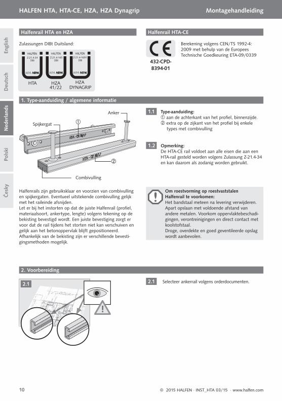
Zulassungen DIBt Duitsland:
Halfenrail HTA en HZA
2.1
1.1
1.2
Type-aanduiding: aan de achterkant van het profi el, binnenzijde. extra op de zijkant van het profi el bij enkele types met combivulling
Opmerking: De HTA-CE rail voldoet aan alle eisen die aan een HTA-rail gesteld worden volgens Zulassung Z-21.4-34 en kan daarom als zodanig worden gebruikt.
Selecteer ankerrail volgens orderdocumenten.
HTA HZA HZADYNAGRIP41/22
Z-21.4-34 Z-21.4-145 Z-21.4-1691
Anker
Spijkergat
Combivulling
Halfenrail HTA-CE
Berekening volgens CEN/TS 1992-4: 2009 met behulp van de Europees Technische Goedkeuring ETA-09/0339
Halfenrails zijn gebruiksklaar en voorzien van combivulling en spijkergaten. Eventueel uitstekende combivulling gelijk met het raileinde afsnijden. Let er bij het instorten op dat de juiste Halfenrail (profi el, materiaalsoort, ankertype, lengte) volgens tekening op de bekisting bevestigd wordt. Een juiste bevestiging zorgt er voor dat de rail tijdens het storten niet kan verschuiven en gelijk aan het betonoppervlak blijft gepositioneerd. Afhankelijk van de bekisting zijn er verschillende bevesti-gingsmethoden mogelijk.
432-CPD-8394-01
2. Voorbereiding
1. Type-aanduiding / algemene informatie
!
Om roestvorming op roestvaststalen Halfenrail te voorkomen: Het bandstaal meteen na levering verwijderen. Apart opslaan met voldoende afstand van andere metalen. Voorkom oppervlaktebeschadi-gingen, verontreinigingen en direct contact met koolstofstaal. Droge, overdekte en goed geventileerde opslag wordt aanbevolen.
2.1
© 2015 HALFEN · INST_HTA 03/15 · www.halfen.com10
HALFEN HTA, HTA-CE, HZA, HZA Dynagrip Montagehandleiding Č
esky
Deu
tsch
Engl
ish
Ned
erla
nds
Pols
ki
25 mm 25mm
3.1
≤200(250)mm ≤200(250)mm ≤200(250)mm
25 mm
3.2
25-35 mm
≤200(250)mm
MD
[mm]
3.3.1
3.3
3.3.3
3.3.2
3. Halfenrail - maatstukken
3.1
3.2
3.3
3.3.1
3.3.2
3.3.3
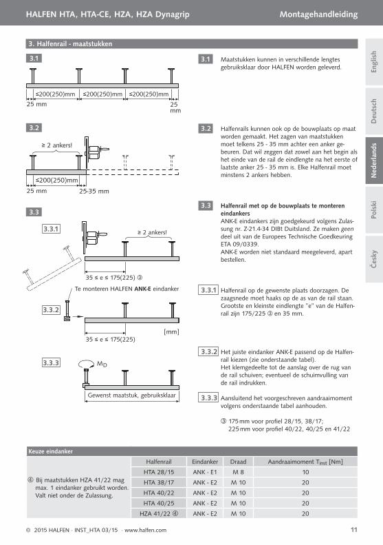
Maatstukken kunnen in verschillende lengtes gebruiksklaar door HALFEN worden geleverd.
Halfenrails kunnen ook op de bouwplaats op maat worden gemaakt. Het zagen van maatstukken moet telkens 25 - 35 mm achter een anker ge-beuren. Dat wil zeggen dat zowel aan het begin als het einde van de rail de eindlengte na het eerste of laatste anker 25 - 35 mm is. Elke Halfenrail moet minstens 2 ankers hebben.
Halfenrail met op de bouwplaats te monteren eindankersANK-E eindankers zijn goedgekeurd volgens Zulas-sung nr. Z-21.4-34 DIBt Duitsland. Ze maken geen deel uit van de Europees Technische Goedkeuring ETA 09/0339.ANK-E worden niet standaard meegeleverd, apart bestellen.
Halfenrail op de gewenste plaats doorzagen. De zaagsnede moet haaks op de as van de rail staan.Grootste en kleinste eindlengte ”e” van de Halfen-rail zijn 175/225 en 35 mm.
Het juiste eindanker ANK-E passend op de Halfen-rail kiezen (zie onderstaande tabel). Het klemgedeelte tot de aanslag over de rug van de rail schuiven; eventueel de schuimvulling van de rail indrukken.
Aansluitend het voorgeschreven aandraaimoment volgens onderstaande tabel aanhouden.
≥ 2 ankers!
≥ 2 ankers!
35 ≤ e ≤ 175(225)
35 ≤ e ≤ 175(225)
Te monteren HALFEN ANK-E eindanker
Gewenst maatstuk, gebruiksklaar
175 mm voor profi el 28/15, 38/17; 225 mm voor profi el 40/22, 40/25 en 41/22
Keuze eindanker
Bij maatstukken HZA 41/22 mag max. 1 eindanker gebruikt worden. Valt niet onder de Zulassung.
Halfenrail Eindanker Draad Aandraaimoment Tinst [Nm]
HTA 28/15 ANK - E1 M 8 10
HTA 38/17 ANK - E2 M 10 20
HTA 40/22 ANK - E2 M 10 20
HTA 40/25 ANK - E2 M 10 20
HZA 41/22 ANK - E2 M 10 20
© 2015 HALFEN · INST_HTA 03/15 · www.halfen.com 11
HALFEN HTA, HTA-CE, HZA, HZA Dynagrip Montagehandleiding
Čes
kyD
euts
chEn
glis
hN
eder
land
sPo
lski
4. Inbouwopties
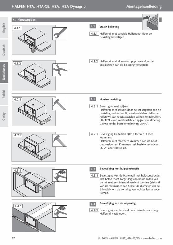
4.1.1 Halfenrail met speciale Halfenbout door de bekisting bevestigen.
4.1.2 Halfenrail met aluminium popnagels door de spijkergaten aan de bekisting vastzetten.
4.2.1 Bevestiging met spijkers:Halfenrail met spijkers door de spijkergaten aan de bekisting vastzetten. Bij roestvaststalen Halfenrail raden wij aan roestvaststalen spijkers te gebruiken. HALFEN levert roestvaststalen spijkers in afmeting 2,8/65 onder bestelomschrijving „ENA“.
Stalen bekisting
Houten bekisting
4.2.2 Bevestiging Halfenrail 28/15 tot 52/34 met krammen:Halfenrail met meerdere krammen aan de bekis-ting vastzetten. Krammen met bestelomschrijving „KRA“ apart bestellen.
4.3.1 Bevestiging van de Halfenrail met hulpconstructie. Het beton moet zorgvuldig aan beide zijden van de rail met een trilnaald verdicht worden (afstand van de rail minder dan 5 keer de diameter van de trilnaald), om de vorming van luchtbellen te voor-komen.
4.4.1 Bevestiging van bovenaf direct aan de wapening: Halfenrail vastbinden.
Bevestiging met hulpconstructie
Bevestiging aan de wapening
4.1.1
4.1.2
4.2.1
4.2.2
4.4.1
4.3.1
4.1
4.2
4.3
4.4
© 2015 HALFEN · INST_HTA 03/15 · www.halfen.com12
HALFEN HTA, HTA-CE, HZA, HZA Dynagrip Montagehandleiding Č
esky
Deu
tsch
Engl
ish
Ned
erla
nds
Pols
ki
In het gebied van de Halfenrail is zorgvuldige betonverdichting noodzakelijk!
Voor correcte montage van de Halfenbou-ten montagehandleiding HS/HSR of HZS raadplegen!
Montage door indrukken van de Halfenrail in de vochtige beton na instorten wordt niet aanbevolen!Indien deze vorm van monteren onvermijdelijk is, is uiterst zorgvuldig verdichten van de beton noodzakelijk (min. 10 seconden voor kortstukken of 20 seconden per meter voor lange rails aan beide zijden met een trilnaald of 10 seconden totaal met een plaat).
Verwijderen van de vulling
Montage van de Halfenbouten
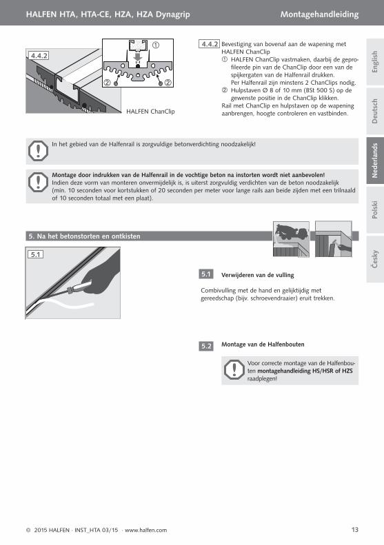
4.4.2 Bevestiging van bovenaf aan de wapening met HALFEN ChanClip
HALFEN ChanClip vastmaken, daarbij de gepro-fi leerde pin van de ChanClip door een van de spijkergaten van de Halfenrail drukken. Per Halfenrail zijn minstens 2 ChanClips nodig.
Hulpstaven Ø 8 of 10 mm (BSt 500 S) op de gewenste positie in de ChanClip klikken.
Rail met ChanClip en hulpstaven op de wapening aanbrengen, hoogte controleren en vastbinden. HALFEN ChanClip
Combivulling met de hand en gelijktijdig met gereedschap (bijv. schroevendraaier) eruit trekken.
5. Na het betonstorten en ontkisten
5.1
5.2
4.4.2
5.1
© 2015 HALFEN · INST_HTA 03/15 · www.halfen.com 13
HALFEN HTA, HTA-CE, HZA, HZA Dynagrip Montagehandleiding
Čes
kyD
euts
chEn
glis
hN
eder
land
sPo
lski
Dla uniknięcia tworzenia się na szynach ze stali nierdzewnej zanieczyszczeń, należy niezwłocznie po dostarczeniu, usunąć taśmy do transportu. Szyny magazynować osobno, w wystarczającej odległości od innych wyrobów metalowych. Należy unikać bezpośredniego kon-taktu z elementami ze stali czarnej. Zalecane jest magazynowanie szyn w suchych, dobrze wentylowanych zadaszonych pomieszczeniach.
Aprobaty Techniczne: AT-15-8539/2010, AT-15-7791/2012
Kotwy szynowe HTA i HZA do wbetonowania
2.1
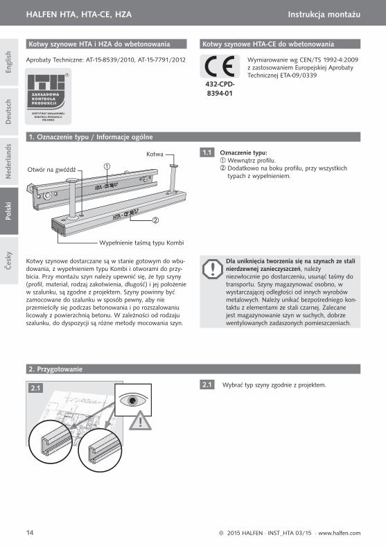
1.1 Oznaczenie typu: Wewnątrz profi lu. Dodatkowo na boku profi lu, przy wszystkich
typach z wypełnieniem.
Wybrać typ szyny zgodnie z projektem.
Kotwa
Otwór na gwóźdź
Wypełnienie taśmą typu Kombi
Kotwy szynowe HTA-CE do wbetonowania
Wymiarowanie wg CEN/TS 1992-4:2009 z zastosowaniem Europejskiej Aprobaty Technicznej ETA-09/0339
Kotwy szynowe dostarczane są w stanie gotowym do wbu-dowania, z wypełnieniem typu Kombi i otworami do przy-bicia. Przy montażu szyn należy upewnić się, że typ szyny (profi l, materiał, rodzaj zakotwienia, długość) i jej położenie w szalunku, są zgodne z projektem. Szyny powinny być zamocowane do szalunku w sposób pewny, aby nie przemieściły się podczas betonowania i po rozszalowaniu licowały z powierzchnią betonu. W zależności od rodzaju szalunku, do dyspozycji są różne metody mocowania szyn.
432-CPD-8394-01
2. Przygotowanie
1. Oznaczenie typu / Informacje ogólne
!
2.1
CERTYFIKAT ZAKŁADOWEJKONTROLI PRODUKCJI
ITB-0308/Z
© 2015 HALFEN · INST_HTA 03/15 · www.halfen.com14
HALFEN HTA, HTA-CE, HZA Instrukcja montażu Č
esky
Deu
tsch
Engl
ish
Ned
erla
nds
Pols
ki
25 mm 25mm
3.1
≤200(250)mm ≤200(250)mm ≤200(250)mm
25 mm
3.2
25-35 mm
≤200(250)mm
MD
[mm]
3.3.1
3.3
3.3.3
3.3.2
3. Kotwy szynowe – krótkie odcinki i docinanie na budowie
3.1
3.2
3.3
3.3.1
3.3.2
3.3.3
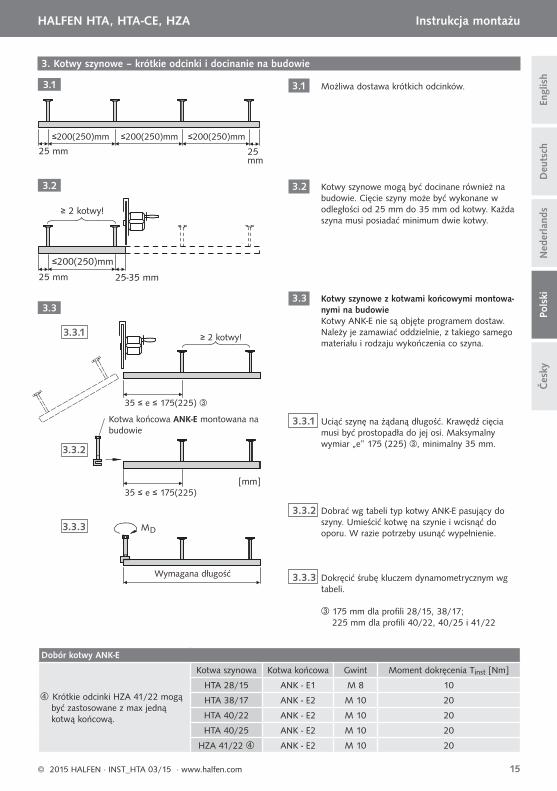
Możliwa dostawa krótkich odcinków.
Kotwy szynowe mogą być docinane również na budowie. Cięcie szyny może być wykonane w odległości od 25 mm do 35 mm od kotwy. Każda szyna musi posiadać minimum dwie kotwy.
Kotwy szynowe z kotwami końcowymi montowa-nymi na budowieKotwy ANK-E nie są objęte programem dostaw. Należy je zamawiać oddzielnie, z takiego samego materiału i rodzaju wykończenia co szyna.
Uciąć szynę na żądaną długość. Krawędź cięcia musi być prostopadła do jej osi. Maksymalny wymiar „e” 175 (225) , minimalny 35 mm.
Dobrać wg tabeli typ kotwy ANK-E pasujący do szyny. Umieścić kotwę na szynie i wcisnąć do oporu. W razie potrzeby usunąć wypełnienie.
Dokręcić śrubę kluczem dynamometrycznym wg tabeli.
≥ 2 kotwy!
≥ 2 kotwy!
35 ≤ e ≤ 175(225)
35 ≤ e ≤ 175(225)
175 mm dla profi li 28/15, 38/17; 225 mm dla profi li 40/22, 40/25 i 41/22
Dobór kotwy ANK-E
Krótkie odcinki HZA 41/22 mogą być zastosowane z max jedną kotwą końcową.
Kotwa szynowa Kotwa końcowa Gwint Moment dokręcenia Tinst [Nm]
HTA 28/15 ANK - E1 M 8 10
HTA 38/17 ANK - E2 M 10 20
HTA 40/22 ANK - E2 M 10 20
HTA 40/25 ANK - E2 M 10 20
HZA 41/22 ANK - E2 M 10 20
Kotwa końcowa ANK-E montowana na budowie
Wymagana długość
© 2015 HALFEN · INST_HTA 03/15 · www.halfen.com 15
HALFEN HTA, HTA-CE, HZA Instrukcja montażu
Čes
kyD
euts
chEn
glis
hN
eder
land
sPo
lski
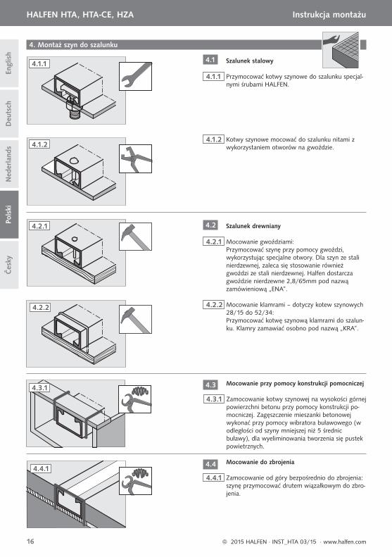
4. Montaż szyn do szalunku
4.1.1 Przymocować kotwy szynowe do szalunku specjal-nymi śrubami HALFEN.
4.1.2 Kotwy szynowe mocować do szalunku nitami z wykorzystaniem otworów na gwoździe.
4.2.1 Mocowanie gwoździami:Przymocować szynę przy pomocy gwoździ, wykorzystując specjalne otwory. Dla szyn ze stali nierdzewnej, zaleca się stosowanie również gwoździ ze stali nierdzewnej. Halfen dostarcza gwoździe nierdzewne 2,8/65mm pod nazwą zamówieniową „ENA”.
Szalunek stalowy
Szalunek drewniany
4.2.2 Mocowanie klamrami – dotyczy kotew szynowych 28/15 do 52/34:Przymocować kotwę szynową klamrami do szalun-ku. Klamry zamawiać osobno pod nazwą „KRA”.
4.3.1 Zamocowanie kotwy szynowej na wysokości górnej powierzchni betonu przy pomocy konstrukcji po-mocniczej. Zagęszczenie mieszanki betonowej wykonać przy pomocy wibratora buławowego (w odległości od szyny mniejszej niż 5 średnic buławy), dla wyeliminowania tworzenia się pustek powietrznych.
4.4.1 Zamocowanie od góry bezpośrednio do zbrojenia: szynę przymocować drutem wiązałkowym do zbro-jenia.
Mocowanie przy pomocy konstrukcji pomocniczej
Mocowanie do zbrojenia
4.1.1
4.1.2
4.2.1
4.2.2
4.4.1
4.3.1
4.1
4.2
4.3
4.4
© 2015 HALFEN · INST_HTA 03/15 · www.halfen.com16
HALFEN HTA, HTA-CE, HZA Instrukcja montażu Č
esky
Deu
tsch
Engl
ish
Ned
erla
nds
Pols
ki
Należy zwrócić uwagę na odpowiednie zagęszczenie mieszanki betonowej w pobliżu szyny!
Montaż śrub specjalnych HALFEN przeprowadzić wg Instrukcji montażu HS/HSR lub HZS.
Montaż poprzez wciśnięcie szyny w świeżą mieszankę betonową nie jest zalecany!Jeśli nie można uniknąć tego rodzaju montażu, należy zwrócić szczególną uwagę na zagęszczenie mieszanki beto-nowej (przy użyciu wibratora buławowego – zagęszczać min. 10s przy krótkich odcinkach oraz 20s na metr długości po obu stronach dla dłuższych szyn lub 10s na stole wibracyjnym).
Usunięcie wypełnienia
Montaż śrub
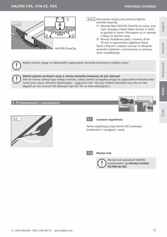
4.4.2 Mocowanie od góry przy pomocy klipsów HALFEN ChanClip
Nasunąć klips HALFEN ChanClip na szynę, przy czym wystający trzpień klipsa wsunąć w otwór na gwózdź w szynie. Wymagane są co najmniej 2 klipsy na odcinek szyny.
Wsunąć dodatkowe pręty o średnicy 8 lub 10 mm w odpowiednie wgłębienie klipsa.
Szynę z klipsami i prętami nasunąć na zbrojenie, sprawdzić położenie i przymocować za pomocą drutu wiązałkowego.
HALFEN ChanClip
Taśmę wypełniającą typu Kombi (KF) podważyć śrubokrętem i wyciągnąć z szyny.
5. Po betonowaniu i rozszalowaniu
5.1
5.2
4.4.2
5.1
© 2015 HALFEN · INST_HTA 03/15 · www.halfen.com 17
HALFEN HTA, HTA-CE, HZA Instrukcja montażu
Čes
kyD
euts
chEn
glis
hN
eder
land
sPo
lski
Všeobecné povolení stavebního dozoru vystavené DIBt (Německý ústav stavební techniky) Berlín
Profi ly Halfen k zabetonování HTA a HZA
2.1
1.1
1.2
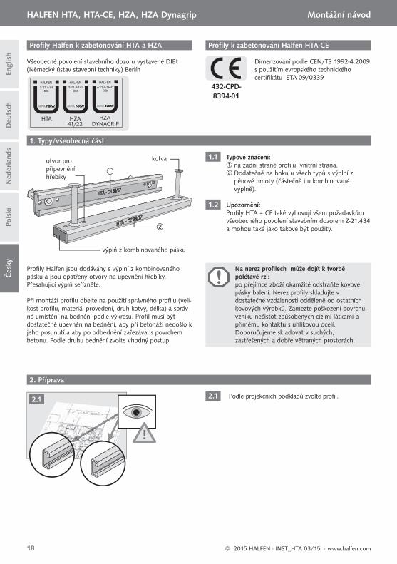
Typové značení: na zadní straně profi lu, vnitřní strana. Dodatečně na boku u všech typů s výplní z
pěnové hmoty (částečně i u kombinované výplně).
Upozornění: Profi ly HTA – CE také vyhovují všem požadavkům všeobecného povolení stavebním dozorem Z-21.434 a mohou také jako takové být použity.
Podle projekčních podkladů zvolte profi l.
HTA HZA HZADYNAGRIP41/22
Z-21.4-34 Z-21.4-145 Z-21.4-1691
kotvaotvor pro připevnění hřebíky
výplň z kombinovaného pásku
Profi ly k zabetonování Halfen HTA-CE
Dimenzování podle CEN/TS 1992-4:2009 s použitím evropského technického certifi kátu ETA-09/0339
Profi ly Halfen jsou dodávány s výplní z kombinovaného pásku a jsou opatřeny otvory na upevnění hřebíky. Přesahující výplň seřízněte.
Při montáži profi lu dbejte na použití správného profi lu (veli-kost profi lu, materiál provedení, druh kotvy, délka) a správ-né umístění na bednění podle výkresu. Profi l musí být dostatečně upevněn na bednění, aby při betonáži nedošlo k jeho posunutí a aby po odbednění zařezával s povrchem betonu. Podle druhu bednění zvolte vhodný postup.
432-CPD-8394-01
2. Příprava
1. Typy/všeobecná část
!
Na nerez profi lech může dojít k tvorbě polétavé rzi: po přejímce zboží okamžitě odstraňte kovové pásky balení. Nerez profi ly skladujte v dostatečné vzdálenosti odděleně od ostatních kovových výrobků. Zamezte poškození povrchu, vzniku nečistot způsobených cizími látkami a přímému kontaktu s uhlíkovou ocelí. Doporučujeme skladovat v suchých, zastřešených a dobře větraných prostorách.
2.1
© 2015 HALFEN · INST_HTA 03/15 · www.halfen.com18
Čes
kyD
euts
chEn
glis
hN
eder
land
sPo
lski
HALFEN HTA, HTA-CE, HZA, HZA Dynagrip Montážní návod
25 mm 25mm
3.1
≤200(250)mm ≤200(250)mm ≤200(250)mm
25 mm
3.2
25-35 mm
≤200(250)mm
MD
[mm]
3.3.1
3.3
3.3.3
3.3.2
3. Profi ly Halfen – krátké kusy a přířezy na míru
3.1
3.2
3.3
3.3.1
3.3.2
3.3.3
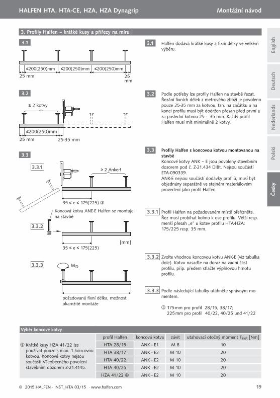
Halfen dodává krátké kusy a fi xní délky ve velkém výběru.
Podle potřeby lze profi ly Halfen na stavbě řezat. Řezání fi xních délek z metrového zboží je povoleno pouze 25-35 mm za kotvou, tzn. na začátku a na konci profi lu musí být dodržen přesah před první a za poslední kotvou 25 - 35 mm. Každý profi l Halfen musí mít minimálně 2 kotvy.
Profi ly Halfen s koncovou kotvou montovanou na stavběKoncové kotvy ANK – E jsou povoleny stavebním dozorem pod č. Z-21.434 DIBt. Nejsou součástí ETA-090339.ANK-E nejsou součástí dodávky profi lů, musí být objednány separátně ve stejném materiálovém provedení jako profi l Halfen.
Profi l Halfen na požadovaném místě přeřízněte. Řez musí probíhat kolmo k ose profi lu. Větší resp. menší přesah „e“ u kotev profi lu HTA-HZA: 175/225 resp. 35 mm.
Zvolte vhodnou koncovou kotvu ANK-E (viz tabulka dole). Kotvu nasaďte na doraz na zadní část profi lu, příp. předem stlačte výplňovou hmotu profi lu.
Podle následující tabulky utáhněte správným mo-mentem.
≥ 2 kotvy
≥ 2 Anker!
35 ≤ e ≤ 175(225)
35 ≤ e ≤ 175(225)
Koncová kotva ANE-E Halfen se montuje na stavbě
požadovaná fi xní délka, možnost okamžité montáže
175 mm pro profi l 28/15, 38/17; 225 mm pro profi l 40/22, 40/25 und 41/22
Výběr koncové kotvy
Krátké kusy HZA 41/22 lze používat pouze s max. 1 koncovou kotvou. Koncové kotvy nejsou součástí Všeobecného povolení stavebním dozorem Z-21.4145.
profi l Halfen koncová kotva závit utahovací otočný moment Tinst [Nm]
HTA 28/15 ANK - E1 M 8 10
HTA 38/17 ANK - E2 M 10 20
HTA 40/22 ANK - E2 M 10 20
HTA 40/25 ANK - E2 M 10 20
HZA 41/22 ANK - E2 M 10 20
© 2015 HALFEN · INST_HTA 03/15 · www.halfen.com 19
Čes
kyD
euts
chEn
glis
hN
eder
land
sPo
lski
HALFEN HTA, HTA-CE, HZA, HZA Dynagrip Montážní návod
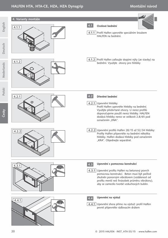
4. Varianty montáže
4.1.1 Profi l Halfen upevněte speciálním šroubem HALFEN na bednění.
4.1.2 Profi l Halfen zafi xujte slepými nýty (ze stavby) na bednění. Využijte otvory pro hřebíky
4.2.1 Upevnění hřebíky: Profi l Halfen upevněte hřebíky na bednění. Využijte předvrtané otvory. U nerez profi lů doporučujeme použít nerez hřebíky. HALFEN dodává hřebíky nerez ve velikosti 2,8/65 pod označením „ENA“.
Ocelové bednění
Dřevěné bednění
4.2.2 Upevnění profi lů Halfen 28/15 až 52/34 hřebíky: Profi ly Halfen připevněte na bednění několika hřebíky. Halfen dodává hřebíky pod označením „KRA”. Objednejte separátně.
4.3.1 Upevnění profi lu Halfen na betonový povrch pomocnou konstrukcí. Beton musí být pečlivě zhutněn ponorným vibrátorem (vzdálenost od profi lu menší než 5násobek průměru vibrátoru), aby se zamezilo tvorbě vzduchových bublin.
4.4.1 Upevnění shora přímo na výztuž: profi l Halfen pevně připevněte rádlovacím drátem
Upevnění s pomocnou konstrukcí
Upevnění na výztuž
4.1.1
4.1.2
4.2.1
4.2.2
4.4.1
4.3.1
4.1
4.2
4.3
4.4
© 2015 HALFEN · INST_HTA 03/15 · www.halfen.com20
Čes
kyD
euts
chEn
glis
hN
eder
land
sPo
lski
HALFEN HTA, HTA-CE, HZA, HZA Dynagrip Montážní návod
V oblasti profi lu Halfen dbejte na pečlivé zhutnění betonu!
Provádějte podle návodu pro montáž šroubů HS/HSR oder HZS Halfen!
Montáž profi lu pouhým zatlačením profi lu Halfen do čerstvého betonu po betonáži nedoporučujeme!Pokud nelze zvolit jiný způsob montáže, musí být beton velmi pečlivě zhutněn (min.10 sekund u krátkých kusů nebo 20 sekund na 1 metr u delších profi lů na obou stranách ponorným vibrátorem nebo 10 sekund vibrační deskou).
Odstraňte výplň
Montáž šroubů
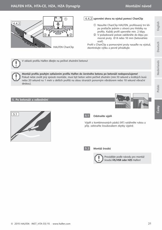
4.4.2 upevnění shora na výztuž pomocí ChanClip
Nasuňte ChanClip HALFEN, profi lovaný trn kli-pu protlačte jedním z otvorů pro hřebíky na profi lu. Každý profi l upevněte min. 2 klipy.
V požadované poloze zaklikněte do klipu po-mocné pruty Ø 8 nebo 10 mm (betonářská ocel).
Profi l s ChanClip a pomocnými pruty nasaďte na výztuž, zkontrolujte výšku a pevně přirádlujte. HALFEN ChanClip
Výplň z kombinovaných pásků (KF) vytáhněte rukou a příp. odstraňte šroubovákem zbytky výplně.
5. Po betonáži a odbednění
5.1
5.2
4.4.2
5.1
© 2015 HALFEN · INST_HTA 03/15 · www.halfen.com 21
Čes
kyD
euts
chEn
glis
hN
eder
land
sPo
lski
HALFEN HTA, HTA-CE, HZA, HZA Dynagrip Montážní návod
© 2015 HALFEN · INST_HTA 03/15 · www.halfen.com22
HALFEN HTA, HTA-CE, HZA, HZA Dynagrip D
euts
chN
eder
land
sPo
lski
Engl
ish

NOTES REGARDING THIS DOCUMENTTechnical and design changes reserved. The information in this publication is based on state-of-the-art technology at the time of publication. We reserve the right to make technical and design changes at any time. Halfen GmbH shall not accept liability for the accuracy of the information in this publication or for any printing errors.
The Quality Management System of Halfen GmbH is certifi ed for the locations in Germany, France, the Netherlands, Austria, Poland, Switzerland and the Czech Republic acc. to DIN EN ISO 9001:2008, Certifi cate No. QS-281 HH.
Furthermore HALFEN is represented with sales offi ces and distributors worldwide.
Austria HALFEN Gesellschaft m.b.H.Leonard-Bernstein-Str. 101220 Wien
Phone: +43 - 1 - 259 6770 E-Mail: offi [email protected]: www.halfen.at
Fax: +43 - 1 - 259 - 6770 99
Belgium /Luxembourg
HALFEN N.V.Borkelstraat 1312900 Schoten
Phone: +32 - 3 - 658 07 20E-Mail: [email protected]: www.halfen.be
Fax: +32 - 3 - 658 15 33
China HALFEN Construction Accessories Distribution Co.Ltd.Room 601 Tower D, Vantone CentreNo.A6 Chao Yang Men Wai StreetChaoyang District Beijing · P.R. China 100020
Phone: +86 - 10 5907 3200E-Mail: [email protected]: www.halfen.cn
Fax: +86 - 10 5907 3218
Czech Republic HALFEN s.r.o.Business Center ŠafránkovaŠafránkova 1238/1155 00 Praha 5
Phone: +420 - 311 - 690 060E-Mail: [email protected]: www.halfen-deha.cz
Fax: +420 - 235 - 314308
France HALFEN S.A.S.18, rue Goubet75019 Paris
Phone: +33 - 1 - 445231 00E-Mail: [email protected]: www.halfen.fr
Fax: +33 - 1 - 445231 52
Germany HALFEN Vertriebsgesellschaft mbHLiebigstr. 14 40764 Langenfeld
Phone: +49 - 2173 - 970 0E-Mail: [email protected]: www.halfen.de
Fax: +49 - 2173 - 970 225
Italy HALFEN S.r.l. Soc. UnipersonaleVia F.lli Bronzetti N° 2824124 Bergamo
Phone: +39 - 035 - 0760711E-Mail: [email protected]: www.halfen.it
Fax: +39 - 035 - 0760799
Netherlands HALFEN b.v.Oostermaat 37623 CS Borne
Phone: +31 - 74-267 14 49E-Mail: [email protected]: www.halfen.nl
Fax: +31 - 74-2 67 26 59
Norway HALFEN ASPostboks 20804095 Stavanger
Phone: +47 - 51 82 34 00E-Mail: [email protected]: www.halfen.no
Fax: +47 - 51 82 34 01
Poland HALFEN Sp. z o.o.Ul. Obornicka 28760-691 Poznan
Phone: +48 - 61 - 622 14 14E-Mail: [email protected]: www.halfen.pl
Fax: +48 - 61 - 622 14 15
Sweden Halfen ABVädursgatan 5412 50 Göteborg
Phone: +46 - 31 - 98 58 00E-Mail: [email protected]: www.halfen.se
Fax: +46 - 31 - 98 58 01
Switzerland HALFEN Swiss AGHertistrasse 25 8304 Wallisellen
Phone: +41 - 44 - 849 78 78E-Mail: [email protected]: www.halfen.ch
Fax: +41 - 44 - 849 78 79
United Kingdom /Ireland
HALFEN Ltd.A1/A2 Portland CloseHoughton Regis LU5 5AW
Phone: +44 - 1582 - 47 03 00E-Mail: [email protected]: www.halfen.co.uk
Fax: +44 - 1582 - 47 03 04
United States of America
HALFEN USA Inc.8521 FM 1976P.O. Box 547Converse, TX 78109
Phone: +1 800.423.91 40E-Mail: [email protected]: www.halfenusa.com
Fax: +1 877 . 683.4910
For countries not listed HALFEN International
HALFEN International GmbHLiebigstr. 14 40764 Langenfeld / Germany
Phone: +49 - 2173 - 970 - 0 E-Mail: [email protected]: www.halfen.com
Fax: +49 - 2173 - 970 - 849
CONTACT HALFEN WORLDWIDE
HALFEN is represented by subsidiar ies in the fol lowing 14 countr ies, please contact us:
Please contact us: www.halfen.com
© 2
015
HA
LFEN
Gm
bH, G
erm
any
appl
ies
also
to
copy
ing
in e
xtra
cts.
U -
101
- 03/
15
03/
1531
9