Embed Size (px)
Citation preview
GX Configurator-SC Version 2Operating Manual(Pre-defined protocol support function)
-SW2D5C-QSCU-E

A - 1 A - 1
• SAFETY PRECAUTIONS • (Always read these instructions before using this equipment.)
Before using this product, please read this manual and the relevant manuals introduced in this manual carefully and pay full attention to safety to handle the product correctly. The instructions given in this manual are concerned with this product. For the safety instructions of the programmable controller system, please read the CPU module user's manual. In this manual, the safety instructions are ranked as " ! WARNING" and " ! CAUTION".
Indicates that incorrect handling may cause hazardous conditions, resulting in death or severe injury. Indicates that incorrect handling may cause hazardous conditions, resulting in minor or moderate injury or property damage.
Note that the ! CAUTION level may lead to a serious consequence according to the circumstances. Always follow the instructions of both levels because they are important to personal safety. Please save this manual to make it accessible when required and always forward it to the end user. [Startup/Maintenance Precautions]
! CAUTION • Before starting online operations such as a communication test, consider the operation of the
connected device and fully ensure safety.
! WARNING
! CAUTION
A - 2 A - 2
• CONDITIONS OF USE FOR THE PRODUCT • (1) Mitsubishi programmable controller ("the PRODUCT") shall be used in conditions;
i) where any problem, fault or failure occurring in the PRODUCT, if any, shall not lead to any major or serious accident; and ii) where the backup and fail-safe function are systematically or automatically provided outside of the PRODUCT for the case of any problem, fault or failure occurring in the PRODUCT.
(2) The PRODUCT has been designed and manufactured for the purpose of being used in general industries. MITSUBISHI SHALL HAVE NO RESPONSIBILITY OR LIABILITY (INCLUDING, BUT NOT LIMITED TO ANY AND ALL RESPONSIBILITY OR LIABILITY BASED ON CONTRACT, WARRANTY, TORT, PRODUCT LIABILITY) FOR ANY INJURY OR DEATH TO PERSONS OR LOSS OR DAMAGE TO PROPERTY CAUSED BY the PRODUCT THAT ARE OPERATED OR USED IN APPLICATION NOT INTENDED OR EXCLUDED BY INSTRUCTIONS, PRECAUTIONS, OR WARNING CONTAINED IN MITSUBISHI'S USER, INSTRUCTION AND/OR SAFETY MANUALS, TECHNICAL BULLETINS AND GUIDELINES FOR the PRODUCT. ("Prohibited Application") Prohibited Applications include, but not limited to, the use of the PRODUCT in; Nuclear Power Plants and any other power plants operated by Power companies, and/or any other cases in which the public could be affected if any problem or fault occurs in the PRODUCT.
Railway companies or Public service purposes, and/or any other cases in which establishment of a special quality assurance system is required by the Purchaser or End User.
Aircraft or Aerospace, Medical applications, Train equipment, transport equipment such as Elevator and Escalator, Incineration and Fuel devices, Vehicles, Manned transportation, Equipment for Recreation and Amusement, and Safety devices, handling of Nuclear or Hazardous Materials or Chemicals, Mining and Drilling, and/or other applications where there is a significant risk of injury to the public or property.
Notwithstanding the above, restrictions Mitsubishi may in its sole discretion, authorize use of the PRODUCT in one or more of the Prohibited Applications, provided that the usage of the PRODUCT is limited only for the specific applications agreed to by Mitsubishi and provided further that no special quality assurance or fail-safe, redundant or other safety features which exceed the general specifications of the PRODUCTs are required. For details, please contact the Mitsubishi representative in your region.
A - 3 A - 3
REVISIONS
* The manual number is given on the bottom left of the back cover.
Print Date * Manual Number Revision Jun., 2009 SH (NA)-080850ENG-A First printing Jan., 2010 SH (NA)-080850ENG-B Model Addition
L02CPU, L26CPU-BT
Partial corrections
About Manuals, Generic Terms and Abbreviations Used in This Manual, Chapter 1, Section 1.1, Section 3.2, Section 4.1, Section 4.2, Section 8.3.3, Section 8.3.6, Section 9.1, Section 9.3.3, Section 10.1 to 10.3, Chapter 11, Section 11.1 to 11.3, Section 11.3.1, Section 11.3.2, Section 11.4, Chapter 13, Section 13.1 to 13.3, Section 13.4.1 to 13.4.3, Appendix 1, Appendix 2.1 to 2.3, Appendix 3, Appendix 4.1 to 4.4, Appendix 5
Partial additions
CONDITIONS OF USE FOR THE PRODUCT
Sep., 2010 SH (NA)-080850ENG-C Partial corrections
Generic Terms and Abbreviations Used in This Manual, Chapter 2, Section 3.2, Section 4.2, Section 9.3.3, Section 10.1
Partial additions
Section 3.3
Japanese Manual Version SH-080817-D
This manual confers no industrial property rights or any rights of any other kind, nor does it confer any patent licenses. Mitsubishi Electric Corporation cannot be held responsible for any problems involving industrial property rights which may occur as a result of using the contents noted in this manual.
© 2009 MITSUBISHI ELECTRIC CORPORATION
A - 4 A - 4
INTRODUCTION
Thank you for choosing the Mitsubishi MELSOFT series Integrated FA software. Read this manual and make sure you understand the functions and performance of MELSEC series programmable controller thoroughly in advance to ensure correct use. Please make this manual available to the end user.
CONTENTS
SAFETY PRECAUTIONS..............................................................................................................................A- 1 CONDITIONS OF USE FOR THE PRODUCT .............................................................................................A- 2 REVISIONS....................................................................................................................................................A- 3 INTRODUCTION............................................................................................................................................A- 4 CONTENTS....................................................................................................................................................A- 4 About Manuals ...............................................................................................................................................A- 7 How to Use This Manual................................................................................................................................A- 8 Generic Terms and Abbreviations Used in This Manual ..............................................................................A- 9
1. OVERVIEW 1- 1 to 1- 6
1.1 Features .................................................................................................................................................. 1- 3
2. OPERATING ENVIRONMENT 2- 1 to 2- 2
3. FUNCTION LIST 3- 1 to 3- 2
3.1 Function List ............................................................................................................................................ 3- 1 3.2 Applicable CPUs and Modules............................................................................................................... 3- 2 3.3 Applicable versions of relevant products...............................................................................................3- 3
4. PRE-DEFINED PROTOCOL SUPPORT FUNCTION OPERATING PROCEDURE 4- 1 to 4- 3
4.1 Procedure for Setting through Writing..................................................................................................... 4- 1 4.2 Procedure for Debugging......................................................................................................................... 4- 2
5. SCREEN DISPLAY 5- 1 to 5- 3
5.1 Screen Display ......................................................................................................................................... 5- 1 5.2 Menu List .................................................................................................................................................. 5- 2 5.3 Toolbar...................................................................................................................................................... 5- 3 5.4 Status Bar................................................................................................................................................. 5- 3
6. STARTING PRE-DEFINED PROTOCOL SUPPORT FUNCTION 6- 1 to 6- 2
7. ENDING OF PRE-DEFINED PROTOCOL SUPPORT FUNCTION 7- 1 to 7- 2
A - 5 A - 5
8. PROTOCOL SETTING FUNCTION 8- 1 to 8- 14
8.1 File Operation........................................................................................................................................... 8- 1 8.1.1 Creating new files.............................................................................................................................. 8- 1 8.1.2 Opening files...................................................................................................................................... 8- 2 8.1.3 Closing files ....................................................................................................................................... 8- 3 8.1.4 Saving files ........................................................................................................................................ 8- 3
8.2 Communication Type of Protocols .......................................................................................................... 8- 4 8.3 Protocol Edit Operation............................................................................................................................ 8- 5
8.3.1 Adding protocols................................................................................................................................ 8- 7 8.3.2 Changing to editable protocols ......................................................................................................... 8- 8 8.3.3 Protocol detailed setting.................................................................................................................... 8- 9 8.3.4 Setting send/receive parameters in a batch..................................................................................... 8-12 8.3.5 Deleting protocols/packets................................................................................................................ 8-13 8.3.6 Copying and pasting protocols/packets............................................................................................ 8-14
9. PACKET SETTING FUNCTION 9- 1 to 9- 39
9.1 Packet elements....................................................................................................................................... 9- 6 9.2 Packet Edit Operation .............................................................................................................................. 9-25
9.2.1 Adding new elements........................................................................................................................ 9-25 9.2.2 Changing element types ................................................................................................................... 9-26
9.3 Element Setting........................................................................................................................................ 9-27 9.3.1 Setting of Header/Static Data/Terminator ....................................................................................... 9-27 9.3.2 Setting of Length .............................................................................................................................. 9-29 9.3.3 Setting of Non-conversion variable................................................................................................... 9-30 9.3.4 Setting of Conversion variable.......................................................................................................... 9-33 9.3.5 Setting of Check code....................................................................................................................... 9-35 9.3.6 Setting of Non-verified reception ...................................................................................................... 9-36
9.4 Device Batch Setting................................................................................................................................ 9-37 9.5 Setting Device List ................................................................................................................................... 9-39
10. WRITING/READING DATA TO/FROM MODULE 10- 1 to 10- 6
10.1 Writing Data to Module ........................................................................................................................ 10- 1 10.2 Reading Data from Module.................................................................................................................. 10- 3 10.3 Verifying Data with Module .................................................................................................................. 10- 4
11. DEBUGGING SUPPORT FUNCTIONS 11- 1 to 11- 15
11.1 Selecting Module for Debugging ......................................................................................................... 11- 2 11.2 Protocol Execution Log Display........................................................................................................... 11- 3 11.3 Circuit Trace ......................................................................................................................................... 11- 6
11.3.1 Starting the circuit trace ................................................................................................................ 11- 6 11.3.2 Circuit trace option ........................................................................................................................ 11- 9 11.3.3 Opening the circuit trace file ......................................................................................................... 11-11 11.3.4 Saving the circuit trace file ............................................................................................................ 11-11
11.4 State Monitor ........................................................................................................................................ 11-12
A - 6 A - 6
12. PRINT 12- 1 to 12- 5
12.1 Start ...................................................................................................................................................... 12- 1 12.2 Print Examples ..................................................................................................................................... 12- 2
13. SETTINGS FOR Q SERIES C24N / L SERIES C24 MODULE 13- 1 to 13- 36
13.1 I/O Signals of Programmable Controller CPU .................................................................................... 13- 1 13.2 Pre-defined Protocol Ready (X1D)...................................................................................................... 13- 2 13.3 List of Applications and Assignments of Buffer Memory .................................................................... 13- 7 13.4 Dedicated Instruction ........................................................................................................................... 13-17
13.4.1 Dedicated instructions and available devices .............................................................................. 13-17 13.4.2 G(P). CPRTCL .............................................................................................................................. 13-18 13.4.3 Functional protocol........................................................................................................................ 13-25
13.5 Programming example......................................................................................................................... 13-27 13.5.1 System configuration/wiring example........................................................................................... 13-27 13.5.2 Communication data ..................................................................................................................... 13-28 13.5.3 Communication settings................................................................................................................ 13-29
APPENDICES App- 1 to App- 26
Appendix 1 Help Function..........................................................................................................................App- 1 Appendix 2 Operation Image of Each Communication Type of Protocol.................................................App- 2
Appendix 2.1 In case where communication type is ‘Send only’ ..........................................................App- 2 Appendix 2.2 In case where communication type is ‘Receive only’ .....................................................App- 3 Appendix 2.3 In case where communication type is ‘Send & receive’ .................................................App- 5
Appendix 3 Verification Operation of Receive Packet ..............................................................................App- 7 Appendix 4 Data Examples of Packet Elements.......................................................................................App- 8
Appendix 4.1 Length ..............................................................................................................................App- 8 Appendix 4.2 Non-conversion variable..................................................................................................App-10 Appendix 4.3 Conversion variable .........................................................................................................App-12 Appendix 4.4 Check code ......................................................................................................................App-15 Appendix 4.5 Non-verified reception......................................................................................................App-24
Appendix 5 Functions Modified from the Previous Version......................................................................App-25
INDEX Index- 1 to Index- 2
A - 7 A - 7
About Manuals
The following lists the manuals relevant to this software package. These manuals are separately available if necessary.
Related Manuals
Manual Name Manual Number (Model Code)
Q Corresponding Serial Communication Module User's Manual (Basic) Explains the outline, applicable system configuration, specifications, pre-operation procedure, basic data
communication method with the other device, maintenance, inspection, and troubleshooting for use of
the module.
(Sold separately)
SH-080006 (13JL86)
MELSEC-L Serial Communication Module User's Manual (Basic) Explains the specifications and usage of the module's special functions, the settings for use of the
special functions, and the method of data communication with the other device.
(Sold separately)
SH-080894ENG (13JZ40)
MELSEC-Q/L Communication Module User's Manual (Application) Explains the specifications and usage of the module's special functions, the settings for use of the
special functions, and the method of data communication with the other device.
(Sold separately)
SH-080007 (13JL87)
MELSEC-Q/L MELSEC Communication Protocol Reference Manual Explains how the other device performs read, write, etc. of PLC CPU data by making communication in
the MC protocol using the serial communication module/Ethernet module.
(Sold separately)
SH-080008 (13JF89)
GX Developer Version 8 Operating Manual (Startup) Explains the system configuration, installation method, and startup method of GX Developer.
(Sold separately)
SH-080372E (13JU40)
GX Developer Version 8 Operating Manual Explains the program creation method, printout method, monitor method, debugging method, etc. using
GX Developer.
(Sold separately)
SH-080373E (13JU41)
GX Developer Version 8 Operating Manual (Function Block) Explains the function block creation method, printout method, etc. using GX Developer.
(Sold separately)
SH-080376E (13JU44)
GX Configurator-SC Version 2 Operating Manual (Protocol FB support function) Explains the features, usage, and .setting method of each parameter of the protocol FB support function
which supports the creation of programs for data communication by modules.
(Sold separately)
SH-080393E (13JU46)
REMARK
The manuals are available separately in printed form as options. Please place an order with the manual number (model code) in the above table.
A - 8 A - 8
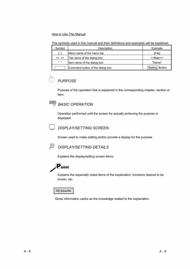
How to Use This Manual The symbols used in this manual and their definitions and examples will be explained.
Symbol Description Example
[ ] Menu name of the menu bar [File] << >> Tab name of the dialog box <<Main>>
" " Item name of the dialog box "Name"
Command button of the dialog box Setting Button
PURPOSE
Purpose of the operation that is explained in the corresponding chapter, section or item.
BASIC OPERATION
Operation performed until the screen for actually achieving the purpose is displayed.
DISPLAY/SETTING SCREEN
Screen used to make setting and/or provide a display for the purpose.
DISPLAY/SETTING DETAILS
Explains the display/setting screen items.
Explains the especially noted items of the explanation, functions desired to be known, etc.
REMARK
Gives information useful as the knowledge related to the explanation.
A - 9 A - 9
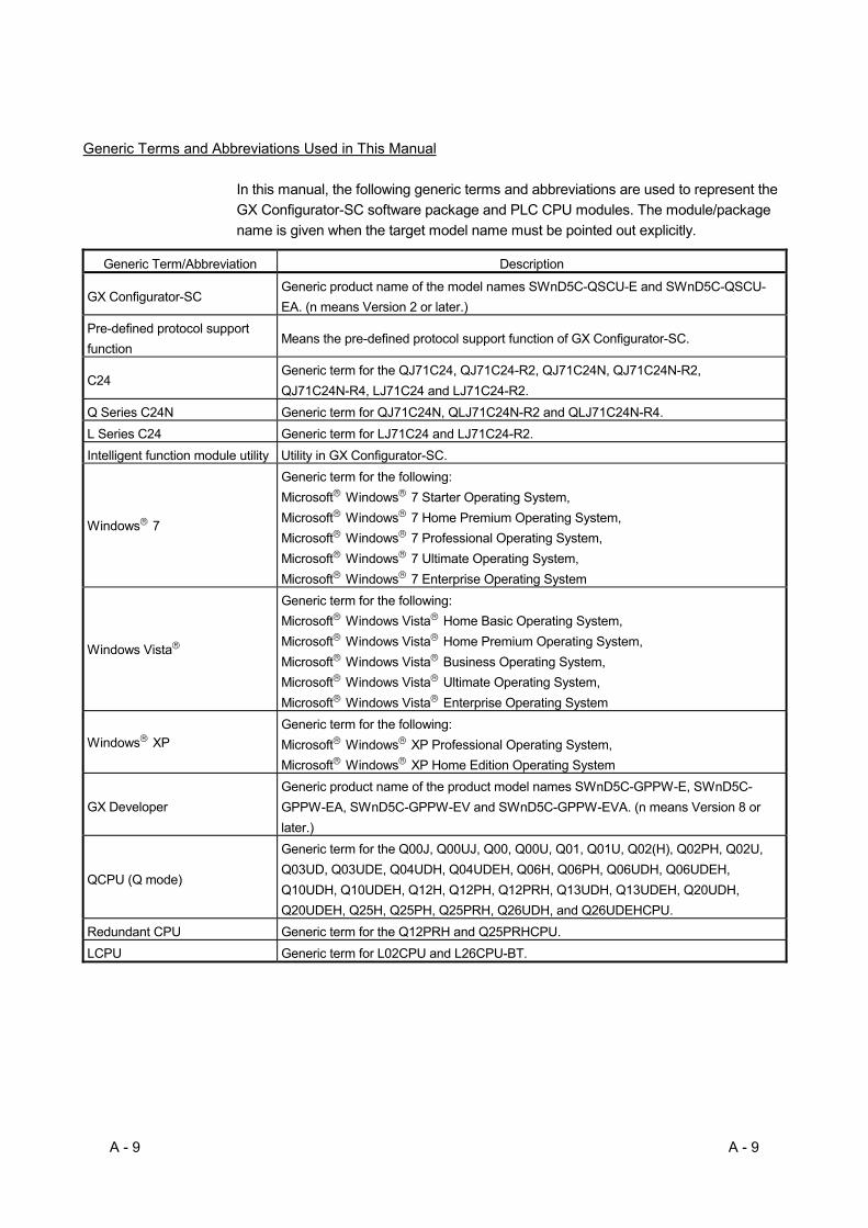
Generic Terms and Abbreviations Used in This Manual
In this manual, the following generic terms and abbreviations are used to represent the GX Configurator-SC software package and PLC CPU modules. The module/package name is given when the target model name must be pointed out explicitly.
Generic Term/Abbreviation Description
GX Configurator-SC Generic product name of the model names SWnD5C-QSCU-E and SWnD5C-QSCU-EA. (n means Version 2 or later.)
Pre-defined protocol support function
Means the pre-defined protocol support function of GX Configurator-SC.
C24 Generic term for the QJ71C24, QJ71C24-R2, QJ71C24N, QJ71C24N-R2, QJ71C24N-R4, LJ71C24 and LJ71C24-R2.
Q Series C24N Generic term for QJ71C24N, QLJ71C24N-R2 and QLJ71C24N-R4. L Series C24 Generic term for LJ71C24 and LJ71C24-R2. Intelligent function module utility Utility in GX Configurator-SC.
Windows R 7
Generic term for the following: Microsoft R Windows R 7 Starter Operating System, Microsoft R Windows R 7 Home Premium Operating System, Microsoft R Windows R 7 Professional Operating System, Microsoft R Windows R 7 Ultimate Operating System, Microsoft R Windows R 7 Enterprise Operating System
Windows Vista R
Generic term for the following: Microsoft R Windows Vista R Home Basic Operating System, Microsoft R Windows Vista R Home Premium Operating System, Microsoft R Windows Vista R Business Operating System, Microsoft R Windows Vista R Ultimate Operating System, Microsoft R Windows Vista R Enterprise Operating System
Windows R XP Generic term for the following: Microsoft R Windows R XP Professional Operating System, Microsoft R Windows R XP Home Edition Operating System
GX Developer Generic product name of the product model names SWnD5C-GPPW-E, SWnD5C-GPPW-EA, SWnD5C-GPPW-EV and SWnD5C-GPPW-EVA. (n means Version 8 or later.)
QCPU (Q mode)
Generic term for the Q00J, Q00UJ, Q00, Q00U, Q01, Q01U, Q02(H), Q02PH, Q02U, Q03UD, Q03UDE, Q04UDH, Q04UDEH, Q06H, Q06PH, Q06UDH, Q06UDEH, Q10UDH, Q10UDEH, Q12H, Q12PH, Q12PRH, Q13UDH, Q13UDEH, Q20UDH, Q20UDEH, Q25H, Q25PH, Q25PRH, Q26UDH, and Q26UDEHCPU.
Redundant CPU Generic term for the Q12PRH and Q25PRHCPU. LCPU Generic term for L02CPU and L26CPU-BT.

A - 10 A - 10
MEMO
1 - 1 1 - 1
MELSOFT1 OVERVIEW
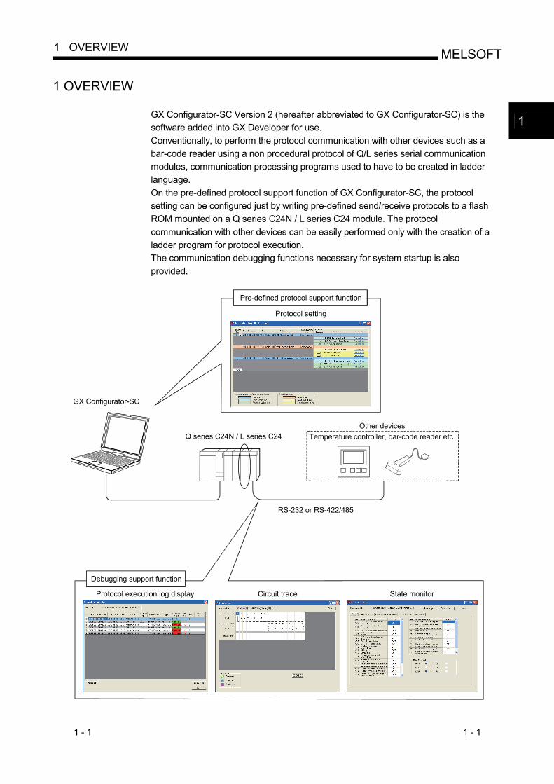
1 OVERVIEW
GX Configurator-SC Version 2 (hereafter abbreviated to GX Configurator-SC) is the software added into GX Developer for use. Conventionally, to perform the protocol communication with other devices such as a bar-code reader using a non procedural protocol of Q/L series serial communication modules, communication processing programs used to have to be created in ladder language. On the pre-defined protocol support function of GX Configurator-SC, the protocol setting can be configured just by writing pre-defined send/receive protocols to a flash ROM mounted on a Q series C24N / L series C24 module. The protocol communication with other devices can be easily performed only with the creation of a ladder program for protocol execution. The communication debugging functions necessary for system startup is also provided.
GX Configurator-SC
Pre-defined protocol support function
Debugging support function
Q series C24N / L series C24
RS-232 or RS-422/485
Protocol setting
Other devicesTemperature controller, bar-code reader etc.
Protocol execution log display Circuit trace State monitor
1
1 - 2 1 - 2
MELSOFT1 OVERVIEW
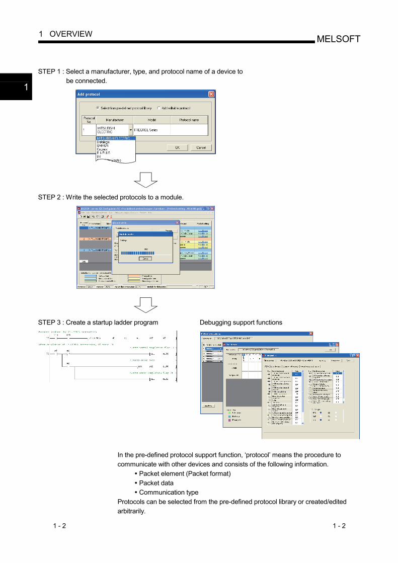
STEP 1 : Select a manufacturer, type, and protocol name of a device to
be connected.
STEP 2 : Write the selected protocols to a module.
STEP 3 : Create a startup ladder program
Debugging support functions
In the pre-defined protocol support function, ‘protocol’ means the procedure to communicate with other devices and consists of the following information.
Packet element (Packet format) Packet data Communication type
Protocols can be selected from the pre-defined protocol library or created/edited arbitrarily.
1
1 - 3 1 - 3
MELSOFT1 OVERVIEW
1.1 Features
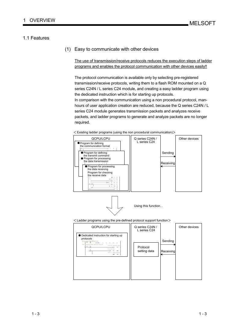
(1) Easy to communicate with other devices
The use of transmission/receive protocols reduces the execution steps of ladder programs and enables the protocol communication with other devices easily!!
The protocol communication is available only by selecting pre-registered transmission/receive protocols, writing them to a flash ROM mounted on a Q series C24N / L series C24 module, and creating a easy ladder program using the dedicated instruction which is for starting up protocols. In comparison with the communication using a non procedural protocol, man-hours of user application creation are reduced, because the Q series C24N / L series C24 module generates transmission packets and analyzes receive packets, and ladder programs to generate and analyze packets are no longer required.
Program for definingthe communication format
Program for definingthe transmit commandProgram for processingthe data transmission
QCPU/LCPU
QCPU/LCPU
Existing ladder programs (using the non procedural communication)
Q series C24N / L series C24
Sending
Receiving
Other devices
Using this function...
Ladder programs using the pre-defined protocol support function
Dedicated instruction for starting upprotocols
Q series C24N / L series C24
Protocolsetting data
Sending
Receiving
Other devices
Program for processingthe data receivingProgram for checkingthe receive data
1 - 4 1 - 4
MELSOFT1 OVERVIEW
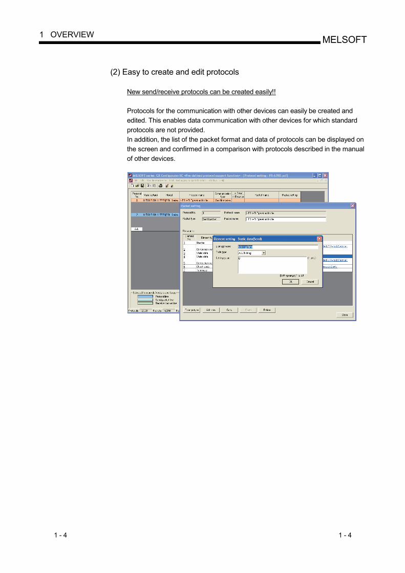
(2) Easy to create and edit protocols
New send/receive protocols can be created easily!!
Protocols for the communication with other devices can easily be created and edited. This enables data communication with other devices for which standard protocols are not provided. In addition, the list of the packet format and data of protocols can be displayed on the screen and confirmed in a comparison with protocols described in the manual of other devices.
1 - 5 1 - 5
MELSOFT1 OVERVIEW
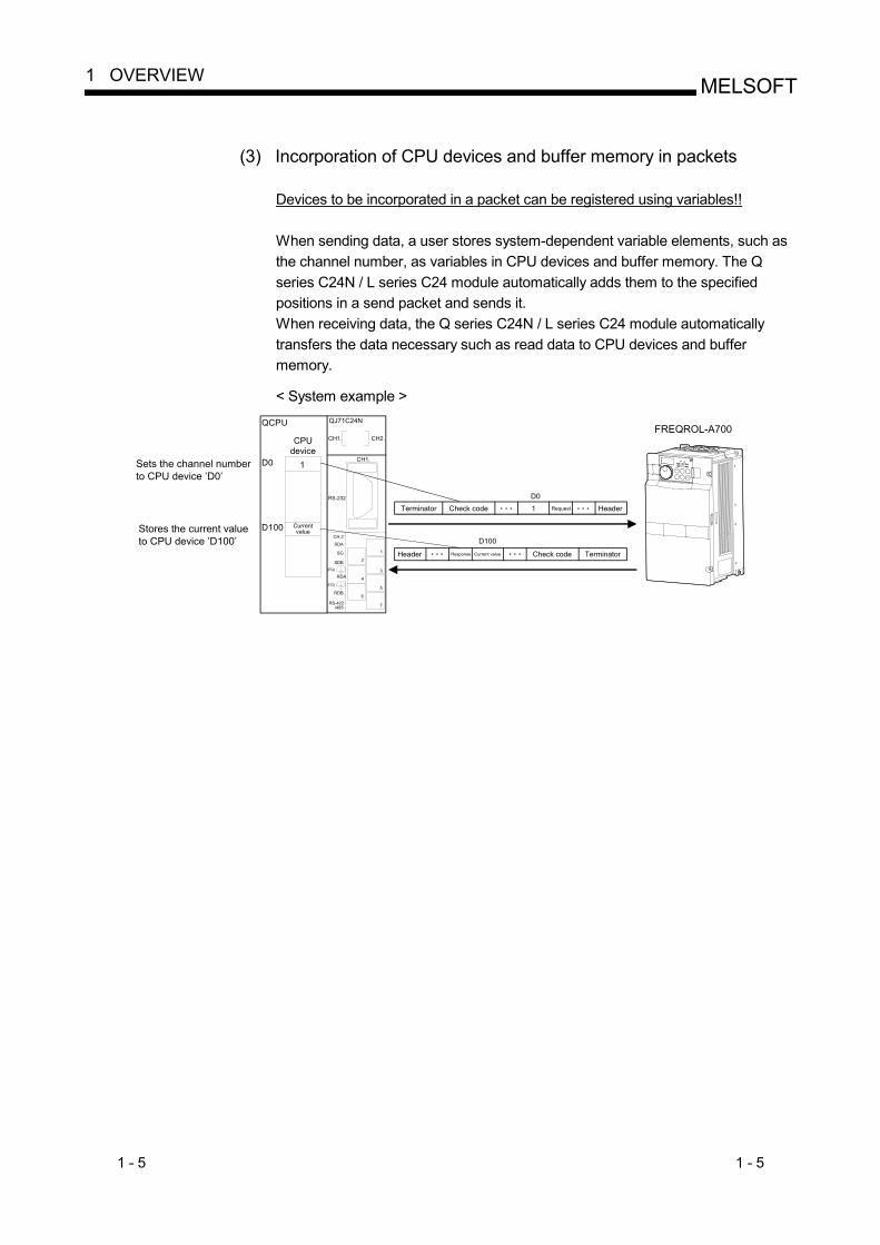
(3) Incorporation of CPU devices and buffer memory in packets
Devices to be incorporated in a packet can be registered using variables!!
When sending data, a user stores system-dependent variable elements, such as the channel number, as variables in CPU devices and buffer memory. The Q series C24N / L series C24 module automatically adds them to the specified positions in a send packet and sends it. When receiving data, the Q series C24N / L series C24 module automatically transfers the data necessary such as read data to CPU devices and buffer memory.
< System example >
RS-232
CH.2
SDA
SG
SDB(FG)
RDA
(FG)
RDB
RS-422 /485
CH1.
CH2.CH1.
2
1
3
4
5
6
7
QJ71C24NQCPU
D0
D100
Sets the channel numberto CPU device ’D0’
1
D0
D100
1
FREQROL-A700
Stores the current valueto CPU device ’D100’
CPUdevice
Currentvalue
Terminator Check code Request Header
Response Current valueHeader Check code Terminator
1 - 6 1 - 6
MELSOFT1 OVERVIEW
(4) Communication debugging support
Reduced debugging work for system construction!!
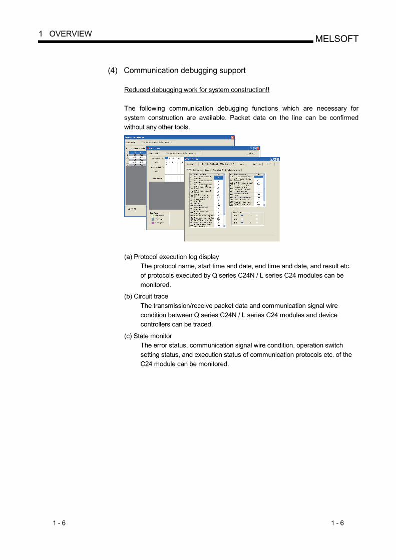
The following communication debugging functions which are necessary for system construction are available. Packet data on the line can be confirmed without any other tools.
(a) Protocol execution log display
The protocol name, start time and date, end time and date, and result etc. of protocols executed by Q series C24N / L series C24 modules can be monitored.
(b) Circuit trace The transmission/receive packet data and communication signal wire condition between Q series C24N / L series C24 modules and device controllers can be traced.
(c) State monitor The error status, communication signal wire condition, operation switch setting status, and execution status of communication protocols etc. of the C24 module can be monitored.
2 - 1 2 - 1
MELSOFT2 OPERATING ENVIRONMENT
2 OPERATING ENVIRONMENT
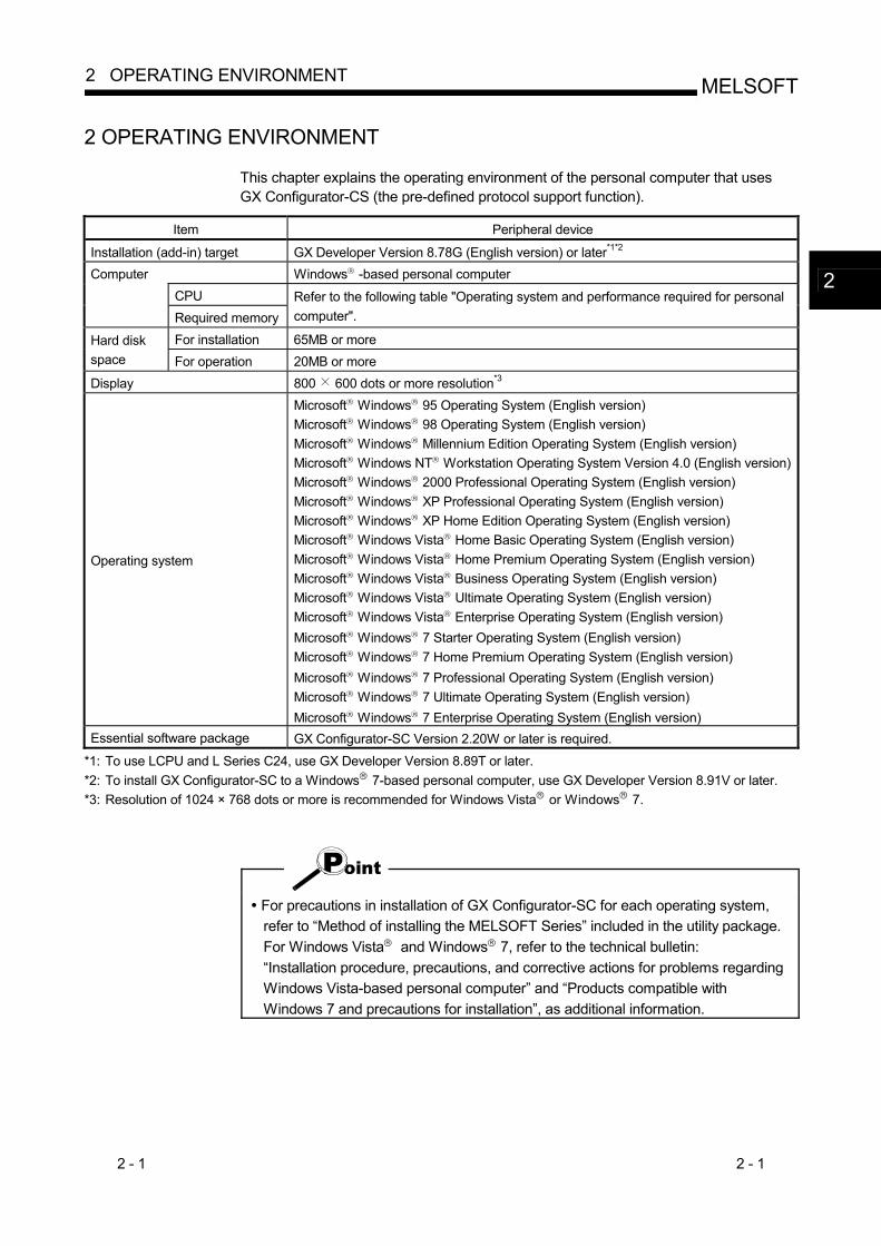
This chapter explains the operating environment of the personal computer that uses GX Configurator-CS (the pre-defined protocol support function).
Item Peripheral device
Installation (add-in) target GX Developer Version 8.78G (English version) or later*1*2 Computer Windows R -based personal computer
CPU Required memory
Refer to the following table "Operating system and performance required for personal computer".
For installation 65MB or more Hard disk space For operation 20MB or more Display 800 600 dots or more resolution*3
Operating system
Microsoft R Windows R 95 Operating System (English version) Microsoft R Windows R 98 Operating System (English version) Microsoft R Windows R Millennium Edition Operating System (English version) Microsoft R Windows NT R Workstation Operating System Version 4.0 (English version)Microsoft R Windows R 2000 Professional Operating System (English version) Microsoft R Windows R XP Professional Operating System (English version) Microsoft R Windows R XP Home Edition Operating System (English version) Microsoft R Windows Vista R Home Basic Operating System (English version) Microsoft R Windows Vista R Home Premium Operating System (English version) Microsoft R Windows Vista R Business Operating System (English version) Microsoft R Windows Vista R Ultimate Operating System (English version) Microsoft R Windows Vista R Enterprise Operating System (English version) Microsoft R Windows R 7 Starter Operating System (English version) Microsoft R Windows R 7 Home Premium Operating System (English version) Microsoft R Windows R 7 Professional Operating System (English version) Microsoft R Windows R 7 Ultimate Operating System (English version) Microsoft R Windows R 7 Enterprise Operating System (English version)
Essential software package GX Configurator-SC Version 2.20W or later is required.
*1: To use LCPU and L Series C24, use GX Developer Version 8.89T or later. *2: To install GX Configurator-SC to a Windows R 7-based personal computer, use GX Developer Version 8.91V or later. *3: Resolution of 1024 × 768 dots or more is recommended for Windows Vista R or Windows R 7.
For precautions in installation of GX Configurator-SC for each operating system, refer to “Method of installing the MELSOFT Series” included in the utility package. For Windows Vista R and Windows R 7, refer to the technical bulletin: “Installation procedure, precautions, and corrective actions for problems regarding Windows Vista-based personal computer” and “Products compatible with Windows 7 and precautions for installation”, as additional information.
2
2 - 2 2 - 2
MELSOFT2 OPERATING ENVIRONMENT
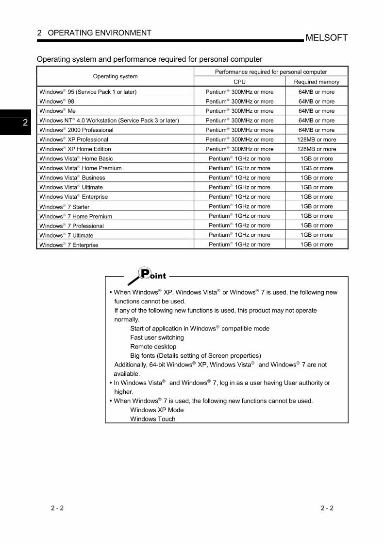
Operating system and performance required for personal computer Performance required for personal computer
Operating system CPU Required memory
Windows R 95 (Service Pack 1 or later) Pentium R 300MHz or more 64MB or more Windows R 98 Pentium R 300MHz or more 64MB or more Windows R Me Pentium R 300MHz or more 64MB or more Windows NT R 4.0 Workstation (Service Pack 3 or later) Pentium R 300MHz or more 64MB or more Windows R 2000 Professional Pentium R 300MHz or more 64MB or more Windows R XP Professional Pentium R 300MHz or more 128MB or more Windows R XP Home Edition Pentium R 300MHz or more 128MB or more Windows Vista R Home Basic Pentium R 1GHz or more 1GB or more Windows Vista R Home Premium Pentium R 1GHz or more 1GB or more Windows Vista R Business Pentium R 1GHz or more 1GB or more Windows Vista R Ultimate Pentium R 1GHz or more 1GB or more Windows Vista R Enterprise Pentium R 1GHz or more 1GB or more
Windows R 7 Starter Pentium R 1GHz or more 1GB or more
Windows R 7 Home Premium Pentium R 1GHz or more 1GB or more
Windows R 7 Professional Pentium R 1GHz or more 1GB or more
Windows R 7 Ultimate Pentium R 1GHz or more 1GB or more
Windows R 7 Enterprise Pentium R 1GHz or more 1GB or more
When Windows R XP, Windows Vista R or Windows R 7 is used, the following new functions cannot be used. If any of the following new functions is used, this product may not operate normally.
Start of application in Windows R compatible mode Fast user switching Remote desktop Big fonts (Details setting of Screen properties)
Additionally, 64-bit Windows R XP, Windows Vista R and Windows R 7 are not available. In Windows Vista R and Windows R 7, log in as a user having User authority or higher.
When Windows R 7 is used, the following new functions cannot be used. Windows XP Mode Windows Touch
2
3 - 1 3 - 1
MELSOFT3 FUNCTION LIST
3 FUNCTION LIST
This chapter explains the functions and menu of the pre-defined protocol support function.
3.1 Function List
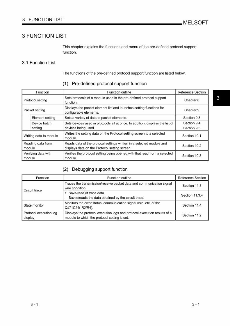
The functions of the pre-defined protocol support function are listed below. (1) Pre-defined protocol support function
Function Function outline Reference Section
Protocol setting Sets protocols of a module used in the pre-defined protocol support function.
Chapter 8
Packet setting Displays the packet element list and launches setting functions for configurable elements.
Chapter 9
Element setting Sets a variety of data to packet elements. Section 9.3
Device batch setting
Sets devices used in protocols all at once. In addition, displays the list of devices being used.
Section 9.4 Section 9.5
Writing data to module Writes the setting data on the Protocol setting screen to a selected module.
Section 10.1
Reading data from module
Reads data of the protocol settings written in a selected module and displays data on the Protocol setting screen.
Section 10.2
Verifying data with module
Verifies the protocol setting being opened with that read from a selected module.
Section 10.3
(2) Debugging support function
Function Function outline Reference Section
Traces the transmission/receive packet data and communication signal wire condition.
Section 11.3 Circuit trace
Save/read of trace data Saves/reads the data obtained by the circuit trace.
Section 11.3.4
State monitor Monitors the error status, communication signal wire, etc. of the QJ71C24(-R2/R4).
Section 11.4
Protocol execution log display
Displays the protocol execution logs and protocol execution results of a module to which the protocol setting is set.
Section 11.2
3
3 - 2 3 - 2
MELSOFT3 FUNCTION LIST
3.2 Applicable CPUs and Modules
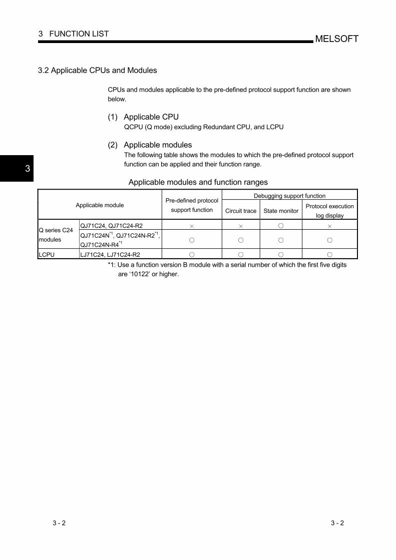
CPUs and modules applicable to the pre-defined protocol support function are shown below. (1) Applicable CPU
QCPU (Q mode) excluding Redundant CPU, and LCPU
(2) Applicable modules The following table shows the modules to which the pre-defined protocol support function can be applied and their function range.
Applicable modules and function ranges
Debugging support function Applicable module
Pre-defined protocol support function Circuit trace State monitor
Protocol execution log display
QJ71C24, QJ71C24-R2 Q series C24 modules QJ71C24N*1, QJ71C24N-R2*1,
QJ71C24N-R4*1
LCPU LJ71C24, LJ71C24-R2 *1: Use a function version B module with a serial number of which the first five digits
are ‘10122’ or higher.
3
3 - 3 3 - 3
MELSOFT3 FUNCTION LIST
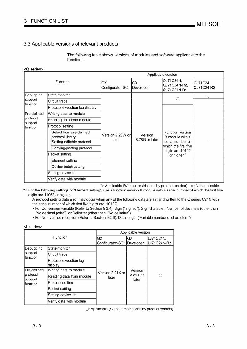
3.3 Applicable versions of relevant products
The following table shows versions of modules and software applicable to the functions.
<Q series> Applicable version
Function GX Configurator-SC
GX Developer
QJ71C24N, QJ71C24N-R2, QJ71C24N-R4
QJ71C24, QJ71C24-R2
State monitor Circuit trace
Debugging support function
Protocol execution log display
Writing data to module
Reading data from module
Protocol setting
Select from pre-defined protocol library Setting editable protocol
Copying/pasting protocol
Packet setting
Element setting
Device batch setting
Setting device list
Pre-defined protocol support function
Verify data with module
Version 2.20W or later
Version 8.78G or later
Function version B module with a serial number of
which the first five digits are 10122
or higher*1
: Applicable (Without restrictions by product version) : Not applicable *1: For the following settings of “Element setting”, use a function version B module with a serial number of which the first five
digits are 11062 or higher. A protocol setting data error may occur when any of the following data are set and written to the Q series C24N with the serial number of which first five digits are ‘10122’. For Conversion variable (Refer to Section 9.3.4): Sign (“Signed”), Sign character, Number of decimals (other than “No decimal point”), or Delimiter (other than “No delimiter”)
For Non-verified reception (Refer to Section 9.3.6): Data length (“variable number of characters”) <L series>
Applicable version Function GX
Configurator-SC GX Developer
LJ71C24N, LJ71C24N-R2
State monitor Circuit trace
Debugging support function
Protocol execution log display Writing data to module
Reading data from module
Protocol setting
Packet setting
Setting device list
Pre-defined protocol support function
Verify data with module
Version 2.21X or later
Version 8.89T or
later
: Applicable (Without restrictions by product version)

3 - 4 3 - 4
MELSOFT3 FUNCTION LIST
MEMO
4 - 1 4 - 1
MELSOFT
4 PRE-DEFINED PROTOCOL SUPPORT FUNCTION OPERATING PROCEDURE
4 PRE-DEFINED PROTOCOL SUPPORT FUNCTION OPERATING PROCEDURE
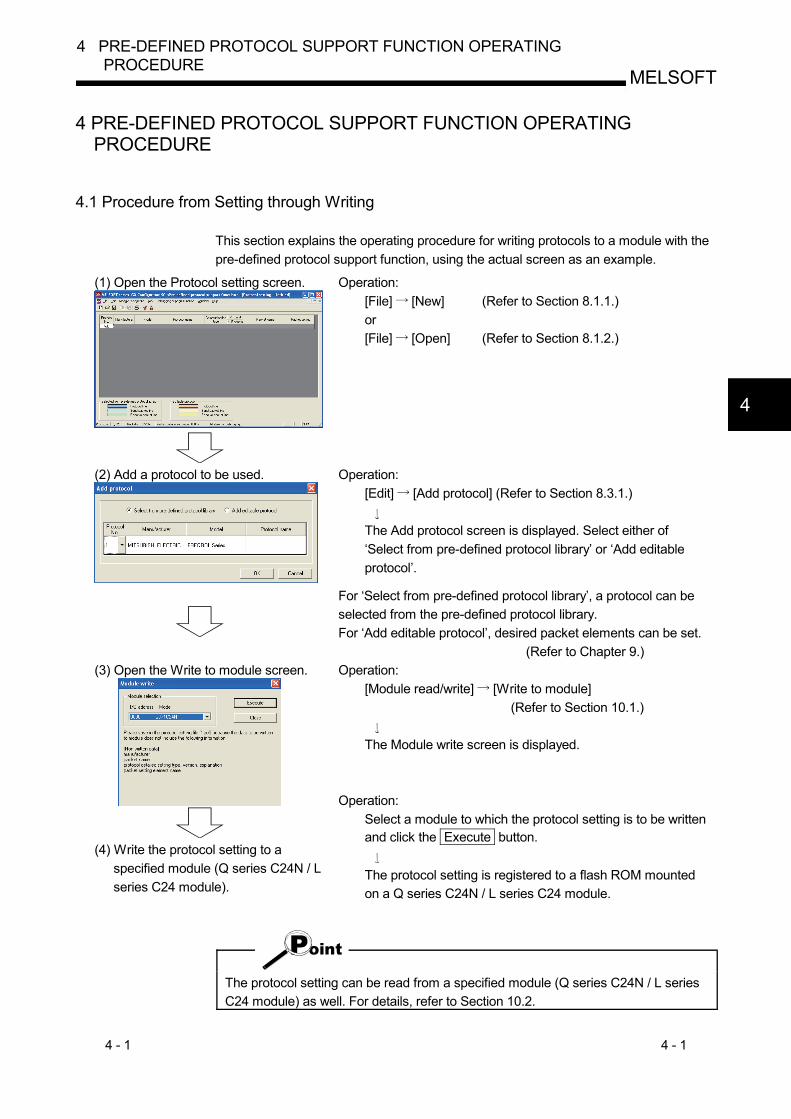
4.1 Procedure from Setting through Writing
This section explains the operating procedure for writing protocols to a module with the pre-defined protocol support function, using the actual screen as an example.
(1) Open the Protocol setting screen.
Operation: [File] [New] (Refer to Section 8.1.1.) or [File] [Open] (Refer to Section 8.1.2.)
(2) Add a protocol to be used.
Operation: [Edit] [Add protocol] (Refer to Section 8.3.1.)
The Add protocol screen is displayed. Select either of ‘Select from pre-defined protocol library’ or ‘Add editable protocol’.
For ‘Select from pre-defined protocol library’, a protocol can be selected from the pre-defined protocol library. For ‘Add editable protocol’, desired packet elements can be set. (Refer to Chapter 9.)
(3) Open the Write to module screen.
(4) Write the protocol setting to a
specified module (Q series C24N / L series C24 module).
Operation: [Module read/write] [Write to module] (Refer to Section 10.1.)
The Module write screen is displayed.
Operation:
Select a module to which the protocol setting is to be written and click the Execute button.
The protocol setting is registered to a flash ROM mounted on a Q series C24N / L series C24 module.
The protocol setting can be read from a specified module (Q series C24N / L series C24 module) as well. For details, refer to Section 10.2.
4
4 - 2 4 - 2
MELSOFT
4 PRE-DEFINED PROTOCOL SUPPORT FUNCTION OPERATING PROCEDURE
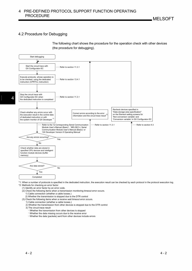
4.2 Procedure for Debugging
The following chart shows the procedure for the operation check with other devices (the procedure for debugging).
Check whether data are stored inspecified CPU devices and intelligent function module devices (buffermemory)
*1: When a number of protocols is specified in the dedicated instruction, the execution result can be checked by each protocol in the protocol execution log.*2: Methods for checking an error factor
(1) Identify an error factor by an error code.(2) Check the following items when a transmission monitoring timeout error occurs.
1) Cable connection (whether a cable looses.)2) Whether the transmission is stopped due to the DTR control
(3) Check the following items when a receive wait timeout error occurs.1) Cable connection (whether a cable looses.)2) Whether the transmission from other devices is stopped due to the DTR control 3) The circuit trace result
Whether the transmission from other devices is stoppedWhether the data missing occurs due to the receive errorWhether the data (packets) sent from other devices include errors
Start debugging
Start the circuit trace withGX Configurator-SC
Execute protocols, whose operation isto be checked, using the dedicated instruction (CPRTCL instruction)
Stop the circuit trace withGX Configurator-SC whenthe dedicated instruction is completed
*1
Check whether any errors occur withthe execution result in the control dataof dedicated instruction or withthe system monitor of GX Developer
Refer to the ’Q Corresponding Serial CommunicationModule User’s Manual (Basic)’ , ’MELSEC-L Serial Communication Module User’s Manual (Basic)’ or’GX Developer Version 8 Operating Manual’
Refer to section 11.3.1
Refer to section 13.4.1
Refer to section 11.3.1
Are any errors occurring?Yes
No
No
Yes
Are data stored?
Completed
Refer to section 11.3.1
Correct errors according to the errorinformation and the circuit trace result
Refer to section 9.3
Recheck devices specified in"Data storage area specification"on the Element setting screens for’Non-conversion variable’ and’Conversion variable’ in GX Configurator-SC
*2
4
4 - 3 4 - 3
MELSOFT
4 PRE-DEFINED PROTOCOL SUPPORT FUNCTION OPERATING PROCEDURE
MEMO

5 - 1 5 - 1
MELSOFT5 SCREEN DISPLAY
5 SCREEN DISPLAY
This chapter explains the screen display and names of the pre-defined protocol support function.
5.1 Screen Display
The basic screen display of the pre-defined protocol support function is shown below.
Status bar
Edit screen
Main menuToolbar
The following table indicates the names and functions.
Name Function
Main menu Select the menu item. Toolbar Click the selected button to execute the function.
Edit screen Protocol setting, the trace screen etc. are available.
Status bar Displays status of various items.
5
5 - 2 5 - 2
MELSOFT5 SCREEN DISPLAY
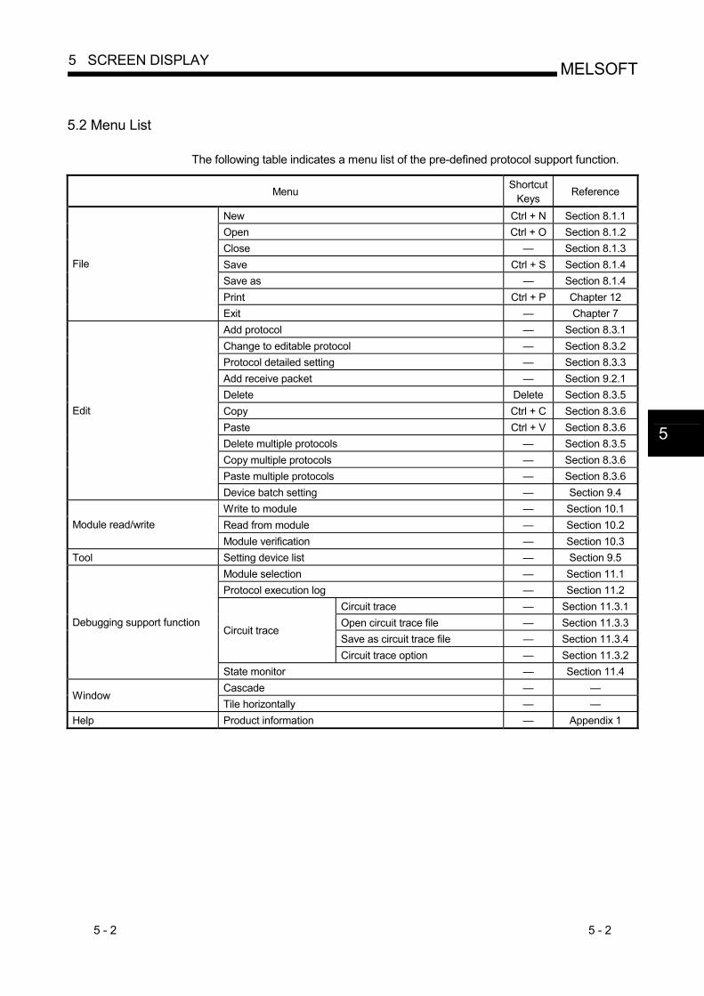
5.2 Menu List
The following table indicates a menu list of the pre-defined protocol support function.
Menu Shortcut
Keys Reference
New Ctrl + N Section 8.1.1 Open Ctrl + O Section 8.1.2 Close — Section 8.1.3 Save Ctrl + S Section 8.1.4 Save as — Section 8.1.4 Print Ctrl + P Chapter 12
File
Exit — Chapter 7 Add protocol — Section 8.3.1 Change to editable protocol — Section 8.3.2 Protocol detailed setting — Section 8.3.3 Add receive packet — Section 9.2.1 Delete Delete Section 8.3.5 Copy Ctrl + C Section 8.3.6 Paste Ctrl + V Section 8.3.6 Delete multiple protocols — Section 8.3.5 Copy multiple protocols — Section 8.3.6 Paste multiple protocols — Section 8.3.6
Edit
Device batch setting — Section 9.4 Write to module — Section 10.1 Read from module — Section 10.2 Module read/write Module verification — Section 10.3
Tool Setting device list — Section 9.5 Module selection — Section 11.1 Protocol execution log — Section 11.2
Circuit trace — Section 11.3.1 Open circuit trace file — Section 11.3.3 Save as circuit trace file — Section 11.3.4
Circuit trace
Circuit trace option — Section 11.3.2
Debugging support function
State monitor — Section 11.4 Cascade — —
Window Tile horizontally — —
Help Product information — Appendix 1
5
5 - 3 5 - 3
MELSOFT5 SCREEN DISPLAY
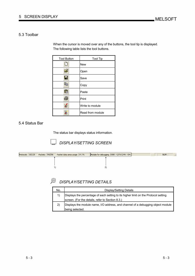
5.3 Toolbar
When the cursor is moved over any of the buttons, the tool tip is displayed. The following table lists the tool buttons.
Tool Button Tool Tip
New
Open
Save
Copy
Paste
Write to module
Read from module
5.4 Status Bar
The status bar displays status information.
DISPLAY/SETTING SCREEN
2)1)
DISPLAY/SETTING DETAILS No. Display/Setting Details
1) Displays the percentage of each setting to its higher limit on the Protocol setting screen. (For the details, refer to Section 8.3.)
2) Displays the module name, I/O address, and channel of a debugging object module being selected.
6 - 1 6 - 1
MELSOFT6 STARTING PRE-DEFINED PROTOCOL SUPPORT FUNCTION
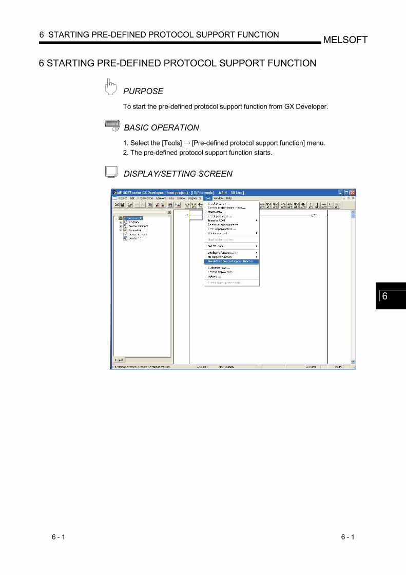
6 STARTING PRE-DEFINED PROTOCOL SUPPORT FUNCTION
PURPOSE To start the pre-defined protocol support function from GX Developer.
BASIC OPERATION 1. Select the [Tools] [Pre-defined protocol support function] menu. 2. The pre-defined protocol support function starts.
DISPLAY/SETTING SCREEN
6
6 - 2 6 - 2
MELSOFT6 STARTING PRE-DEFINED PROTOCOL SUPPORT FUNCTION
MEMO
6
7 - 1 7 - 1
MELSOFT7 ENDING OF PRE-DEFINED PROTOCOL SUPPORT FUNCTION
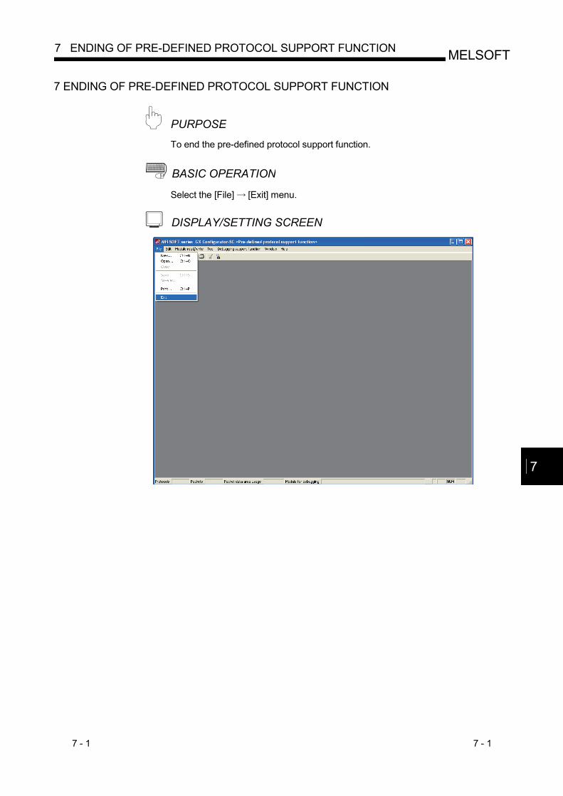
7 ENDING OF PRE-DEFINED PROTOCOL SUPPORT FUNCTION
PURPOSE To end the pre-defined protocol support function.
BASIC OPERATION Select the [File] [Exit] menu.
DISPLAY/SETTING SCREEN
7
7 - 2 7 - 2
MELSOFT7 ENDING OF PRE-DEFINED PROTOCOL SUPPORT FUNCTION
MEMO
7
8 - 1 8 - 1
MELSOFT8 PROTOCOL SETTING FUNCTION
8 PROTOCOL SETTING FUNCTION
The following lists File/Edit operations.
Function Function outline Reference
Creating new files Creates a new protocol setting file. Section 8.1.1 Opening files Opens an existing protocol setting file. Section 8.1.2 Closing files Closes a protocol setting file being open. Section 8.1.3 Saving files "Saves" or "Saves as" a protocol setting file being edited. Section 8.1.4 Adding protocols Adds a protocol. Section 8.3.1 Changing to editable protocols
Changes a protocol selected from the pre-defined protocol library to an editable one.
Section 8.3.2
Protocol detailed setting Configures the number of retries of a protocol and whether to clear OS area (receive data area) before protocol execution etc.
Section 8.3.3
Setting send/receive parameters in a batch
Configures all receive settings/send settings of the protocol detailed setting at once.
Section 8.3.4
Deleting protocols/packets Deletes a protocol/packet. Section 8.3.5 Copying and pasting protocols/packets
Copies and pastes a protocol/packet. Section 8.3.6
8.1 File Operation
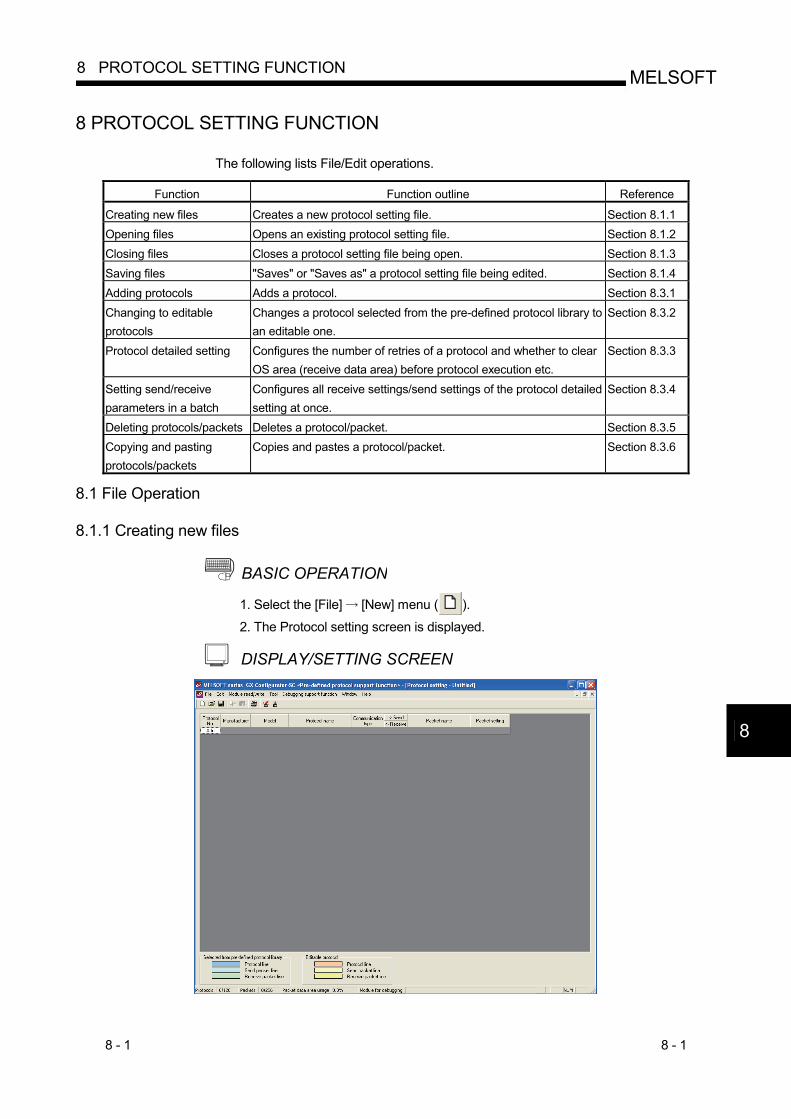
8.1.1 Creating new files
BASIC OPERATION 1. Select the [File] [New] menu ( ).
2. The Protocol setting screen is displayed.
DISPLAY/SETTING SCREEN
8
8 - 2 8 - 2
MELSOFT8 PROTOCOL SETTING FUNCTION
8.1.2 Opening files
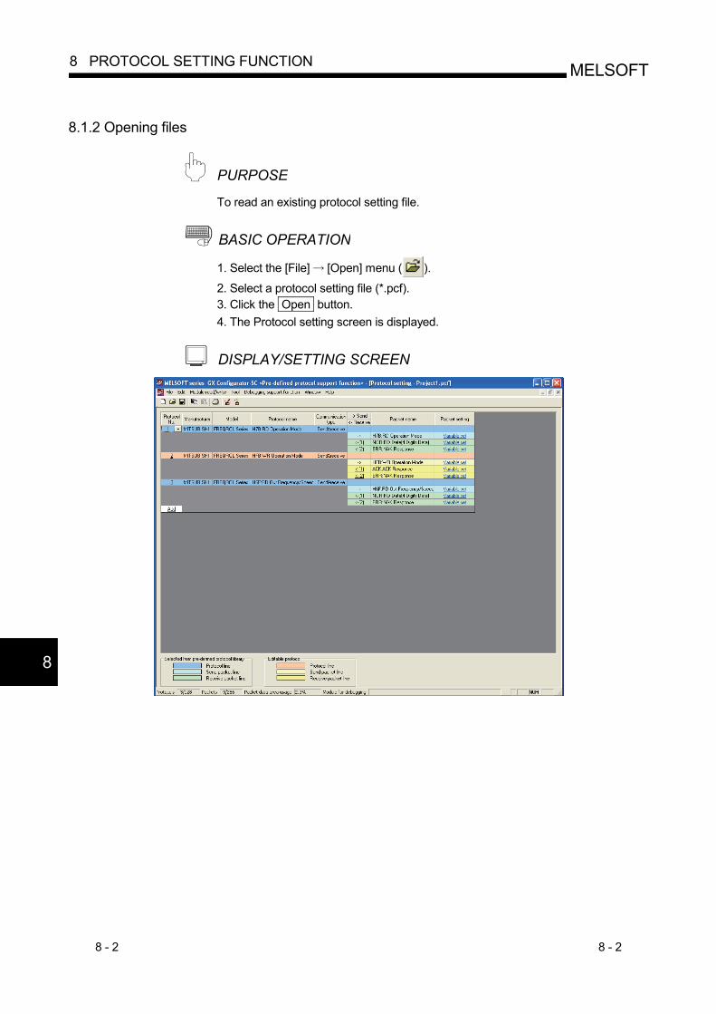
PURPOSE To read an existing protocol setting file.
BASIC OPERATION 1. Select the [File] [Open] menu ( ).
2. Select a protocol setting file (*.pcf). 3. Click the Open button. 4. The Protocol setting screen is displayed.
DISPLAY/SETTING SCREEN
8
8 - 3 8 - 3
MELSOFT8 PROTOCOL SETTING FUNCTION
8.1.3 Closing files
To close a protocol setting file being open.
BASIC OPERATION 1. Select the [File] [Close] menu. 2. If the setting has been changed, the confirmation message for saving a protocol
setting file is displayed. Click the Yes button to save and close the protocol setting file. Click the No button to close the protocol setting file without saving it.
8.1.4 Saving files
PURPOSE Save a protocol setting file being edited.
BASIC OPERATION (1) Saving a protocol setting file over the old one
1. Select the [File] [Save] menu ( ).
2. A protocol setting file being edited is saved over the old one. (2) Saving a protocol setting file with a name
1. Select the [File] [Save as] menu. 2. Set the "File path" and "File name". 3. Click the Save button. 4. A protocol setting file being edited is saved with a name.
PURPOSE
8 - 4 8 - 4
MELSOFT8 PROTOCOL SETTING FUNCTION
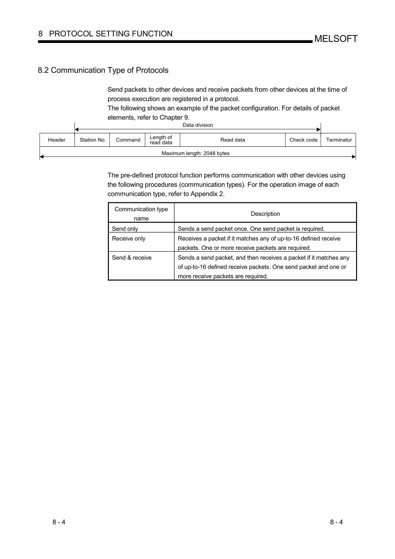
8.2 Communication Type of Protocols
Send packets to other devices and receive packets from other devices at the time of process execution are registered in a protocol. The following shows an example of the packet configuration. For details of packet elements, refer to Chapter 9.
Length ofread data Read dataHeader Station No. Command TerminatorCheck code
Data division
Maximum length: 2048 bytes
The pre-defined protocol function performs communication with other devices using the following procedures (communication types). For the operation image of each communication type, refer to Appendix 2.
Communication type
name Description
Send only Sends a send packet once. One send packet is required. Receive only Receives a packet if it matches any of up-to-16 defined receive
packets. One or more receive packets are required. Send & receive Sends a send packet, and then receives a packet if it matches any
of up-to-16 defined receive packets. One send packet and one or more receive packets are required.
8 - 5 8 - 5
MELSOFT8 PROTOCOL SETTING FUNCTION
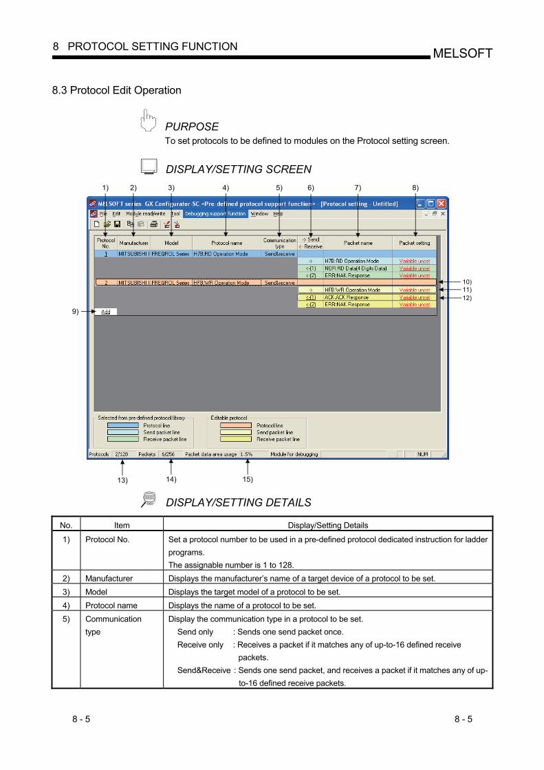
8.3 Protocol Edit Operation
PURPOSE To set protocols to be defined to modules on the Protocol setting screen.
DISPLAY/SETTING SCREEN 1) 2) 3) 5)4) 6) 7) 8)
9)
10)
13) 14) 15)
11)12)
DISPLAY/SETTING DETAILS No. Item Display/Setting Details
1) Protocol No. Set a protocol number to be used in a pre-defined protocol dedicated instruction for ladder programs. The assignable number is 1 to 128.
2) Manufacturer Displays the manufacturer’s name of a target device of a protocol to be set. 3) Model Displays the target model of a protocol to be set. 4) Protocol name Displays the name of a protocol to be set. 5) Communication
type Display the communication type in a protocol to be set.
Send only : Sends one send packet once. Receive only : Receives a packet if it matches any of up-to-16 defined receive
packets. Send&Receive : Sends one send packet, and receives a packet if it matches any of up-
to-16 defined receive packets.
8 - 6 8 - 6
MELSOFT8 PROTOCOL SETTING FUNCTION
No. Item Display/Setting Details
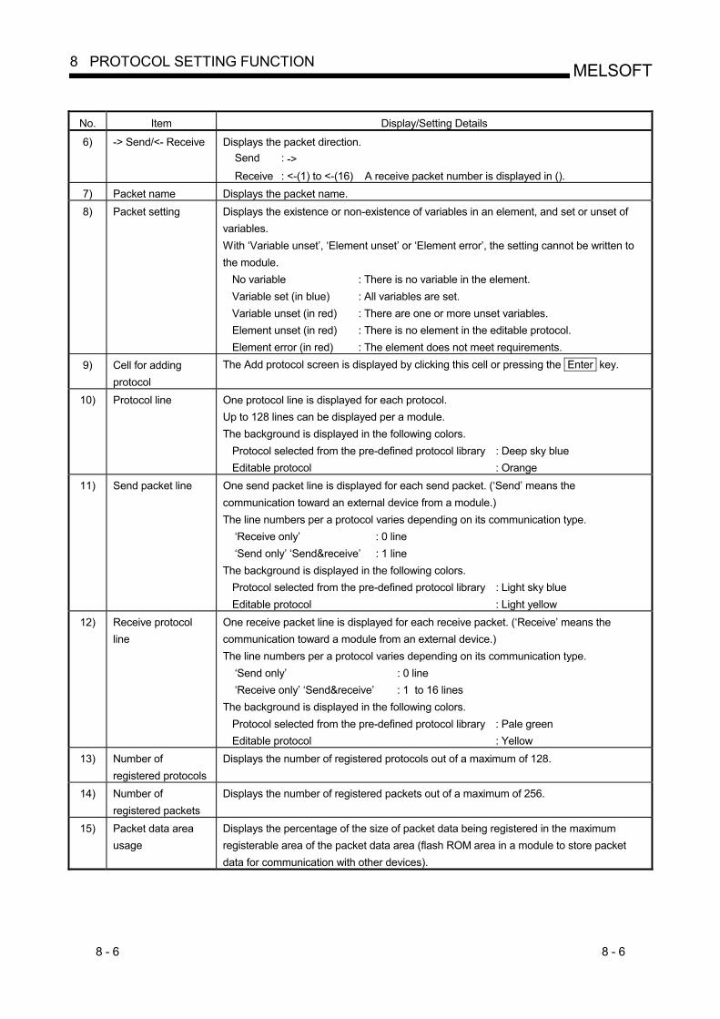
6) -> Send/<- Receive Displays the packet direction. Send : ->
Receive : <-(1) to <-(16) A receive packet number is displayed in (). 7) Packet name Displays the packet name. 8) Packet setting Displays the existence or non-existence of variables in an element, and set or unset of
variables. With ‘Variable unset’, ‘Element unset’ or ‘Element error’, the setting cannot be written to the module.
No variable : There is no variable in the element. Variable set (in blue) : All variables are set. Variable unset (in red) : There are one or more unset variables. Element unset (in red) : There is no element in the editable protocol. Element error (in red) : The element does not meet requirements.
9) Cell for adding protocol
The Add protocol screen is displayed by clicking this cell or pressing the Enter key.
10) Protocol line One protocol line is displayed for each protocol. Up to 128 lines can be displayed per a module. The background is displayed in the following colors.
Protocol selected from the pre-defined protocol library : Deep sky blue Editable protocol : Orange
11) Send packet line One send packet line is displayed for each send packet. (‘Send’ means the communication toward an external device from a module.) The line numbers per a protocol varies depending on its communication type.
‘Receive only’ : 0 line ‘Send only’ ‘Send&receive’ : 1 line
The background is displayed in the following colors. Protocol selected from the pre-defined protocol library : Light sky blue Editable protocol : Light yellow
12) Receive protocol line
One receive packet line is displayed for each receive packet. (‘Receive’ means the communication toward a module from an external device.) The line numbers per a protocol varies depending on its communication type.
‘Send only’ : 0 line ‘Receive only’ ‘Send&receive’ : 1 to 16 lines
The background is displayed in the following colors. Protocol selected from the pre-defined protocol library : Pale green Editable protocol : Yellow
13) Number of registered protocols
Displays the number of registered protocols out of a maximum of 128.
14) Number of registered packets
Displays the number of registered packets out of a maximum of 256.
15) Packet data area usage
Displays the percentage of the size of packet data being registered in the maximum registerable area of the packet data area (flash ROM area in a module to store packet data for communication with other devices).
8 - 7 8 - 7
MELSOFT8 PROTOCOL SETTING FUNCTION
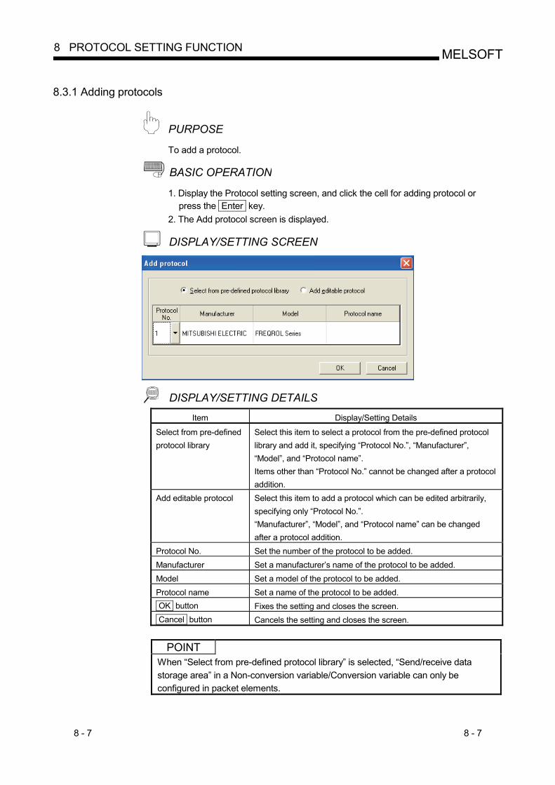
8.3.1 Adding protocols
PURPOSE To add a protocol.
BASIC OPERATION 1. Display the Protocol setting screen, and click the cell for adding protocol or
press the Enter key. 2. The Add protocol screen is displayed.
DISPLAY/SETTING SCREEN
DISPLAY/SETTING DETAILS Item Display/Setting Details
Select from pre-defined protocol library
Select this item to select a protocol from the pre-defined protocol library and add it, specifying “Protocol No.”, “Manufacturer”, “Model”, and “Protocol name”. Items other than “Protocol No.” cannot be changed after a protocol addition.
Add editable protocol Select this item to add a protocol which can be edited arbitrarily, specifying only “Protocol No.”. “Manufacturer”, “Model”, and “Protocol name” can be changed after a protocol addition.
Protocol No. Set the number of the protocol to be added. Manufacturer Set a manufacturer’s name of the protocol to be added. Model Set a model of the protocol to be added. Protocol name Set a name of the protocol to be added. OK button Fixes the setting and closes the screen. Cancel button Cancels the setting and closes the screen.
POINT
When “Select from pre-defined protocol library” is selected, “Send/receive data storage area” in a Non-conversion variable/Conversion variable can only be configured in packet elements.
8 - 8 8 - 8
MELSOFT8 PROTOCOL SETTING FUNCTION
8.3.2 Changing to editable protocols
PURPOSE To change a protocol selected from the pre-defined protocol library to an editable one.
BASIC OPERATION 1. Display the Protocol setting screen, and select a line of a protocol to be changed. 2. Select the [Edit] [Change to editable protocol] menu. 3. The confirmation message is displayed. Click the Yes button.
Once a protocol has been changed to an editable protocol, it cannot be restored.
8 - 9 8 - 9
MELSOFT8 PROTOCOL SETTING FUNCTION
8.3.3 Protocol detailed setting
PURPOSE To configure the number of retries of a protocol and whether to clear OS area (receive data area) before protocol execution etc.
BASIC OPERATION 1. Display the Protocol setting screen, and select a line of a protocol to be set. 2. Select the [Edit] [Protocol detailed setting] menu. 3. The Protocol detailed setting screen is displayed.
DISPLAY/SETTING SCREEN
8 - 10 8 - 10
MELSOFT8 PROTOCOL SETTING FUNCTION
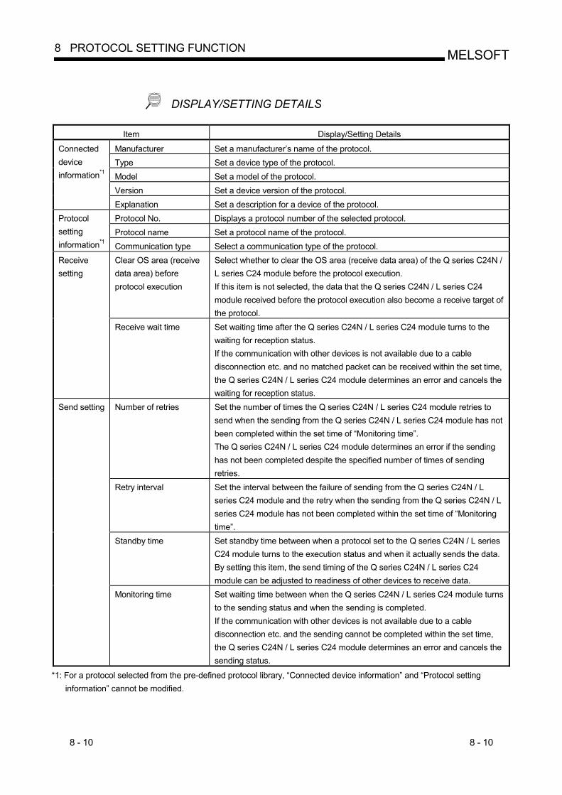
DISPLAY/SETTING DETAILS
Item Display/Setting Details
Manufacturer Set a manufacturer’s name of the protocol. Type Set a device type of the protocol. Model Set a model of the protocol. Version Set a device version of the protocol.
Connected device information*1
Explanation Set a description for a device of the protocol. Protocol No. Displays a protocol number of the selected protocol. Protocol name Set a protocol name of the protocol.
Protocol setting information*1 Communication type Select a communication type of the protocol.
Clear OS area (receive data area) before protocol execution
Select whether to clear the OS area (receive data area) of the Q series C24N / L series C24 module before the protocol execution. If this item is not selected, the data that the Q series C24N / L series C24 module received before the protocol execution also become a receive target of the protocol.
Receive setting
Receive wait time Set waiting time after the Q series C24N / L series C24 module turns to the waiting for reception status. If the communication with other devices is not available due to a cable disconnection etc. and no matched packet can be received within the set time, the Q series C24N / L series C24 module determines an error and cancels the waiting for reception status.
Number of retries Set the number of times the Q series C24N / L series C24 module retries to send when the sending from the Q series C24N / L series C24 module has not been completed within the set time of “Monitoring time”. The Q series C24N / L series C24 module determines an error if the sending has not been completed despite the specified number of times of sending retries.
Retry interval Set the interval between the failure of sending from the Q series C24N / L series C24 module and the retry when the sending from the Q series C24N / L series C24 module has not been completed within the set time of “Monitoring time”.
Standby time Set standby time between when a protocol set to the Q series C24N / L series C24 module turns to the execution status and when it actually sends the data. By setting this item, the send timing of the Q series C24N / L series C24 module can be adjusted to readiness of other devices to receive data.
Send setting
Monitoring time Set waiting time between when the Q series C24N / L series C24 module turns to the sending status and when the sending is completed. If the communication with other devices is not available due to a cable disconnection etc. and the sending cannot be completed within the set time, the Q series C24N / L series C24 module determines an error and cancels the sending status.
*1: For a protocol selected from the pre-defined protocol library, “Connected device information” and “Protocol setting information” cannot be modified.
8 - 11 8 - 11
MELSOFT8 PROTOCOL SETTING FUNCTION
Item Display/Setting Details
Communication parameter batch setting button
Displays the Communication parameter batch setting screen. For details, refer to Section 8.3.4.
OK button Fixes the setting and closes the screen. Cancel button Cancels the setting and closes the screen.
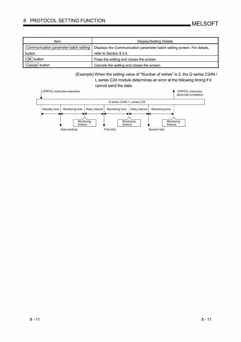
(Example) When the setting value of “Number of retries” is 2, the Q series C24N / L series C24 module determines an error at the following timing if it cannot send the data.
Standby time Monitoring time Retry interval Monitoring time Monitoring time
Monitoringtimeout
Q series C24N / L series C24
Monitoringtimeout
Monitoringtimeout
CPRTCL instructionabnormal completion
CPRTCL instruction execution
Data sending First retry Second retry
Retry interval
8 - 12 8 - 12
MELSOFT8 PROTOCOL SETTING FUNCTION
8.3.4 Setting send/receive parameters in a batch
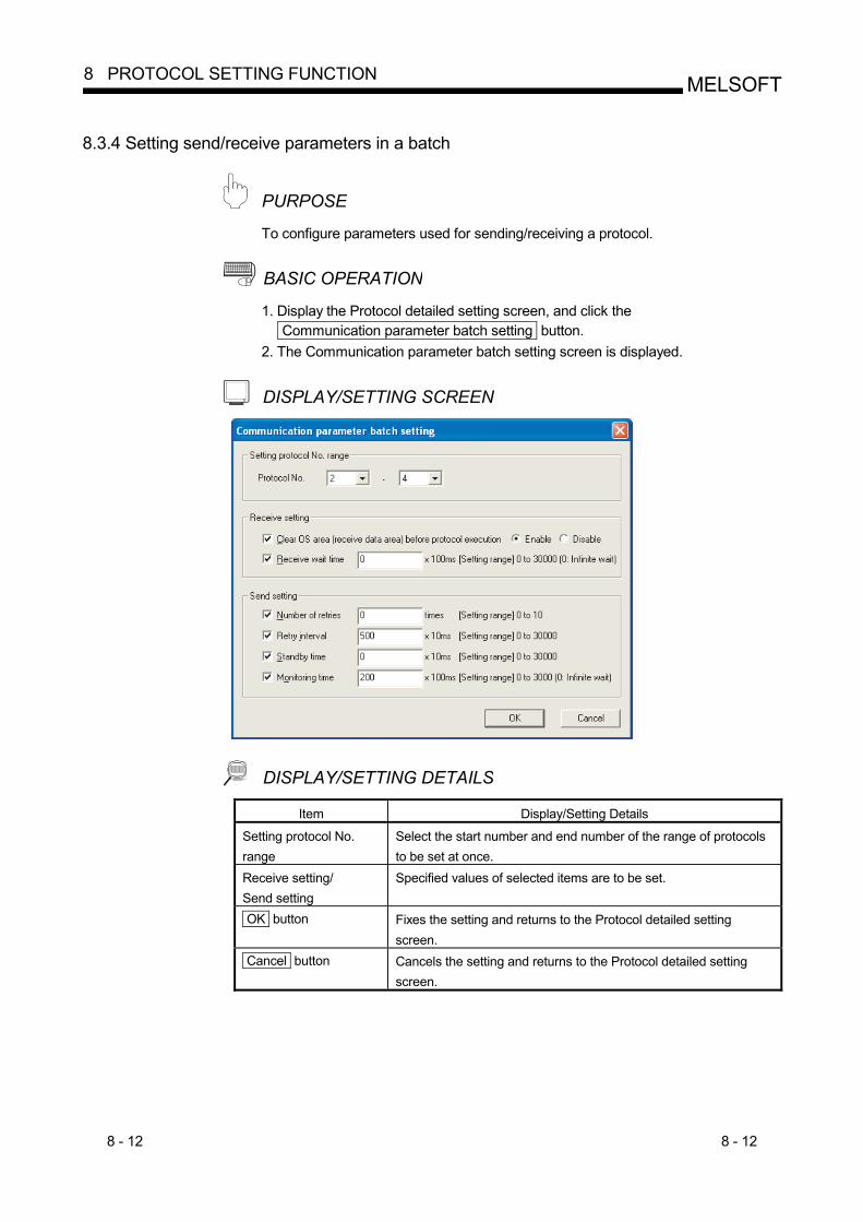
PURPOSE To configure parameters used for sending/receiving a protocol.
BASIC OPERATION 1. Display the Protocol detailed setting screen, and click the
Communication parameter batch setting button. 2. The Communication parameter batch setting screen is displayed.
DISPLAY/SETTING SCREEN
DISPLAY/SETTING DETAILS Item Display/Setting Details
Setting protocol No. range
Select the start number and end number of the range of protocols to be set at once.
Receive setting/ Send setting
Specified values of selected items are to be set.
OK button Fixes the setting and returns to the Protocol detailed setting screen.
Cancel button Cancels the setting and returns to the Protocol detailed setting screen.
8 - 13 8 - 13
MELSOFT8 PROTOCOL SETTING FUNCTION
8.3.5 Deleting protocols/packets
PURPOSE To delete a protocol/packet.
BASIC OPERATION 1. Display the Protocol setting screen, and select a line of a protocol/packet to be
deleted. 2. Select the [Edit] [Delete] menu, or press the Delete key. 3. The line of the protocol/packet is deleted.
To delete multiple protocols at once, select [Edit] [Delete multiple protocols] and specify the range.
A send packet cannot be deleted. A receive packet cannot be deleted when its communication type is “Send & receive” or “Receive only” and there is only one receive packet.
A packet in a protocol selected from the pre-defined protocol library cannot be deleted.
8 - 14 8 - 14
MELSOFT8 PROTOCOL SETTING FUNCTION
8.3.6 Copying and pasting protocols/packets
PURPOSE To copy and paste a protocol/packet.
BASIC OPERATION (1) Copying one by one
1. Display the Protocol setting screen and select a line of a protocol/packet to be copied.
2. Select the [Edit] [Copy] menu, or press the Ctrl + C key. 3. The line of the protocol/packet is copied. 4. Display the destination Protocol setting screen/Packet setting screen, and select
the destination line of a protocol/packet. 5. Select [Edit] [Paste] menu, or press the Ctrl + V key. 6. The selected line of the protocol/packet is overwritten.
(2) Copying more than one in a batch Batch copy is available for diverting multiple protocols/packets to another pre-defined protocol support function window at a time.
1. Display the Protocol setting screen of the copy source. 2. Select the [Edit] [Copy multiple protocols] menu. 3. Specify the range of the protocol numbers to copy in the Copy multiple protocols
screen. 4. Display the destination Protocol setting screen. 5. Select the [Edit] [Paste multiple protocols] menu. 6. Data in the protocol/packet lines of the protocol numbers of the copy source
range are overwritten. (The protocol numbers of the copy source and of the destination become the same.)
A send packet cannot be pasted to a receive packet, and a receive packet cannot be pasted to a send packet.
A packet cannot be pasted to a protocol selected from the pre-defined protocol library.
9 - 1 9 - 1
MELSOFT9 PACKET SETTING FUNCTION
9 PACKET SETTING FUNCTION
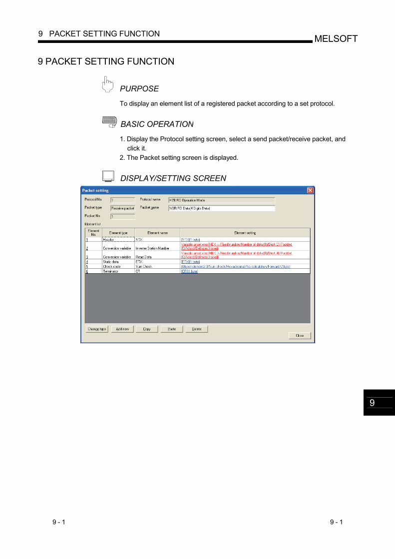
PURPOSE To display an element list of a registered packet according to a set protocol.
BASIC OPERATION 1. Display the Protocol setting screen, select a send packet/receive packet, and
click it. 2. The Packet setting screen is displayed.
DISPLAY/SETTING SCREEN
9
9 - 2 9 - 2
MELSOFT9 PACKET SETTING FUNCTION
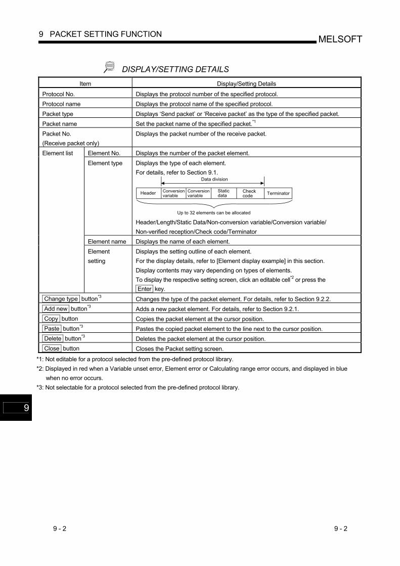
DISPLAY/SETTING DETAILS Item Display/Setting Details
Protocol No. Displays the protocol number of the specified protocol. Protocol name Displays the protocol name of the specified protocol. Packet type Displays ‘Send packet’ or ‘Receive packet’ as the type of the specified packet. Packet name Set the packet name of the specified packet.*1 Packet No. (Receive packet only)
Displays the packet number of the receive packet.
Element No. Displays the number of the packet element. Element type Displays the type of each element.
For details, refer to Section 9.1.
Header Conversionvariable
Staticdata
Checkcode Terminator
Data division
Up to 32 elements can be allocated
Conversionvariable
Header/Length/Static Data/Non-conversion variable/Conversion variable/ Non-verified reception/Check code/Terminator
Element name Displays the name of each element.
Element list
Element setting
Displays the setting outline of each element. For the display details, refer to [Element display example] in this section. Display contents may vary depending on types of elements. To display the respective setting screen, click an editable cell*2 or press the Enter key.
Change type button*3 Changes the type of the packet element. For details, refer to Section 9.2.2. Add new button*3 Adds a new packet element. For details, refer to Section 9.2.1. Copy button Copies the packet element at the cursor position. Paste button*3 Pastes the copied packet element to the line next to the cursor position. Delete button*3 Deletes the packet element at the cursor position. Close button Closes the Packet setting screen.
*1: Not editable for a protocol selected from the pre-defined protocol library. *2: Displayed in red when a Variable unset error, Element error or Calculating range error occurs, and displayed in blue
when no error occurs. *3: Not selectable for a protocol selected from the pre-defined protocol library.
9
9 - 3 9 - 3
MELSOFT9 PACKET SETTING FUNCTION
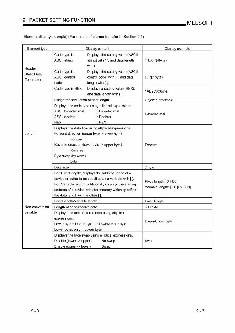
[Element display example] (For details of elements, refer to Section 9.1)
Element type Display content Display example
Code type is ASCII string
Displays the setting value (ASCII string) with “ ”, and data length with ( ).
“TEXT”(4byte)
Code type is ASCII control code
Displays the setting value (ASCII control code) with [ ], and data length with ( ).
[CR](1byte)
Header Static Data Terminator
Code type is HEX Displays a setting value (HEX), and data length with ( ).
1AB2C3(3byte)
Range for calculation of data length Object element3-8 Displays the code type using elliptical expressions. ASCII hexadecimal : Hexadecimal ASCII decimal : Decimal HEX : HEX
Hexadecimal
Displays the data flow using elliptical expressions. Forward direction (upper byte -> lower byte)
: Forward Reverse direction (lower byte -> upper byte) : Reverse Byte swap (by word) : byte
Forward
Length
Data size 2 byte For ‘Fixed length’, displays the address range of a device or buffer to be specified as a variable with [ ]. For ‘Variable length’, additionally displays the starting address of a device or buffer memory which specifies the data length with another [ ].
Fixed length: [D1-D2] Variable length: [D1] [D2-D11]
Fixed length/Variable length Fixed length Length of send/receive data 600 byte Displays the unit of stored data using elliptical expressions. Lower byte + Upper byte : Lower/Upper byte Lower bytes only : Lower byte
Lower/Upper byte
Non-conversion variable
Displays the byte swap using elliptical expressions. Disable (lower -> upper) : No swap Enable (upper -> lower) : Swap
Swap
9 - 4 9 - 4
MELSOFT9 PACKET SETTING FUNCTION
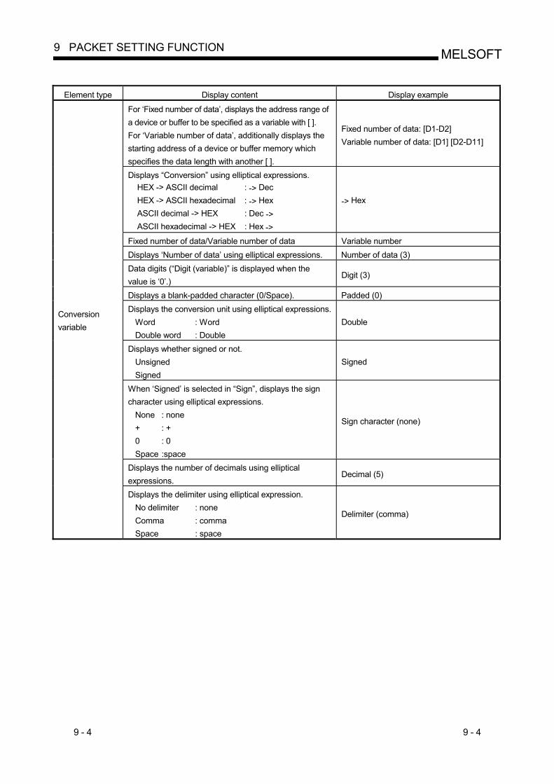
Element type Display content Display example
For ‘Fixed number of data’, displays the address range of a device or buffer to be specified as a variable with [ ]. For ‘Variable number of data’, additionally displays the starting address of a device or buffer memory which specifies the data length with another [ ].
Fixed number of data: [D1-D2] Variable number of data: [D1] [D2-D11]
Displays “Conversion” using elliptical expressions. HEX -> ASCII decimal : -> Dec HEX -> ASCII hexadecimal : -> Hex ASCII decimal -> HEX : Dec -> ASCII hexadecimal -> HEX : Hex ->
-> Hex
Fixed number of data/Variable number of data Variable number Displays ‘Number of data’ using elliptical expressions. Number of data (3) Data digits (“Digit (variable)” is displayed when the value is ‘0’.)
Digit (3)
Displays a blank-padded character (0/Space). Padded (0) Displays the conversion unit using elliptical expressions.
Word : Word Double word : Double
Double
Displays whether signed or not. Unsigned Signed
Signed
When ‘Signed’ is selected in “Sign”, displays the sign character using elliptical expressions.
None : none + : + 0 : 0 Space :space
Sign character (none)
Displays the number of decimals using elliptical expressions.
Decimal (5)
Conversion variable
Displays the delimiter using elliptical expression. No delimiter : none Comma : comma Space : space
Delimiter (comma)
9 - 5 9 - 5
MELSOFT9 PACKET SETTING FUNCTION
Element type Display content Display example
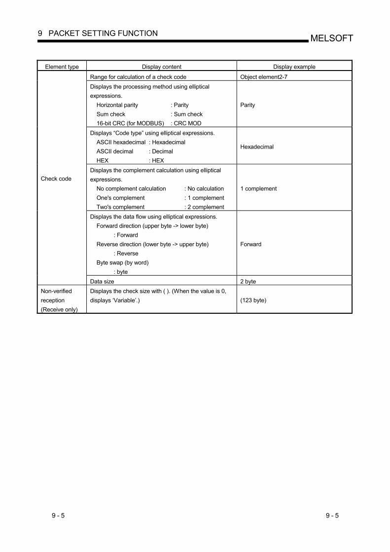
Range for calculation of a check code Object element2-7 Displays the processing method using elliptical expressions.
Horizontal parity : Parity Sum check : Sum check 16-bit CRC (for MODBUS) : CRC MOD
Parity
Displays “Code type” using elliptical expressions. ASCII hexadecimal : Hexadecimal ASCII decimal : Decimal HEX : HEX
Hexadecimal
Displays the complement calculation using elliptical expressions.
No complement calculation : No calculation One's complement : 1 complement Two's complement : 2 complement
1 complement
Displays the data flow using elliptical expressions. Forward direction (upper byte -> lower byte) : Forward Reverse direction (lower byte -> upper byte) : Reverse Byte swap (by word) : byte
Forward
Check code
Data size 2 byte Non-verified reception (Receive only)
Displays the check size with ( ). (When the value is 0, displays ‘Variable’.) (123 byte)
9 - 6 9 - 6
MELSOFT9 PACKET SETTING FUNCTION
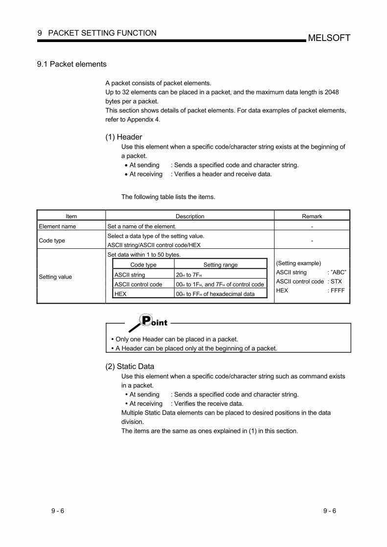
9.1 Packet elements
A packet consists of packet elements. Up to 32 elements can be placed in a packet, and the maximum data length is 2048 bytes per a packet. This section shows details of packet elements. For data examples of packet elements, refer to Appendix 4. (1) Header
Use this element when a specific code/character string exists at the beginning of a packet. • At sending : Sends a specified code and character string. • At receiving : Verifies a header and receive data.
The following table lists the items.
Item Description Remark
Element name Set a name of the element. -
Code type Select a data type of the setting value. ASCII string/ASCII control code/HEX
-
Set data within 1 to 50 bytes.
Code type Setting range
ASCII string 20H to 7FH ASCII control code 00H to 1FH, and 7FH of control code HEX 00H to FFH of hexadecimal data
Setting value
(Setting example) ASCII string : ”ABC” ASCII control code : STX HEX : FFFF
Only one Header can be placed in a packet. A Header can be placed only at the beginning of a packet.
(2) Static Data
Use this element when a specific code/character string such as command exists in a packet.
At sending : Sends a specified code and character string. At receiving : Verifies the receive data.
Multiple Static Data elements can be placed to desired positions in the data division. The items are the same as ones explained in (1) in this section.
9 - 7 9 - 7
MELSOFT9 PACKET SETTING FUNCTION
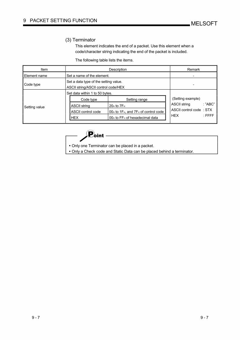
(3) Terminator
This element indicates the end of a packet. Use this element when a code/character string indicating the end of the packet is included.
The following table lists the items.
Item Description Remark
Element name Set a name of the element. -
Code type Set a data type of the setting value. ASCII string/ASCII control code/HEX
-
Set data within 1 to 50 bytes.
Code type Setting range
ASCII string 20H to 7FH ASCII control code 00H to 1FH, and 7FH of control code HEX 00H to FFH of hexadecimal data
Setting value
(Setting example) ASCII string : ”ABC” ASCII control code : STX HEX : FFFF
Only one Terminator can be placed in a packet. Only a Check code and Static Data can be placed behind a terminator.
9 - 8 9 - 8
MELSOFT9 PACKET SETTING FUNCTION
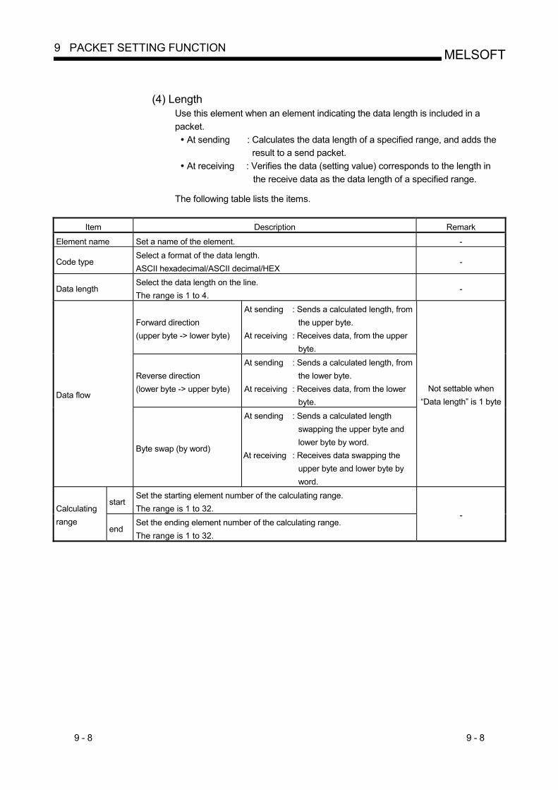
(4) Length
Use this element when an element indicating the data length is included in a packet.
At sending : Calculates the data length of a specified range, and adds the result to a send packet.
At receiving : Verifies the data (setting value) corresponds to the length in the receive data as the data length of a specified range.
The following table lists the items.
Item Description Remark
Element name Set a name of the element. -
Code type Select a format of the data length. ASCII hexadecimal/ASCII decimal/HEX
-
Data length Select the data length on the line. The range is 1 to 4.
-
Forward direction (upper byte -> lower byte)
At sending : Sends a calculated length, from the upper byte.
At receiving : Receives data, from the upper byte.
Reverse direction (lower byte -> upper byte)
At sending : Sends a calculated length, from the lower byte.
At receiving : Receives data, from the lower byte.
Data flow
Byte swap (by word)
At sending : Sends a calculated length swapping the upper byte and lower byte by word.
At receiving : Receives data swapping the upper byte and lower byte by word.
Not settable when “Data length” is 1 byte
start Set the starting element number of the calculating range. The range is 1 to 32. Calculating
range end
Set the ending element number of the calculating range. The range is 1 to 32.
-
9 - 9 9 - 9
MELSOFT9 PACKET SETTING FUNCTION
Only one Length can be placed in a packet. When there is no element other than a Length, an element error occurs. When the number of digits of calculation result is greater than that specified in “Data length”, digits greater than the specified digit are omitted (ignored). Example) When ‘2 bytes’ is specified in “Data length” and the calculation result is
‘123 bytes’, the data length is considered as ‘23’. When any of a Non-conversion variable (Variable length), Conversion variable (Variable number of data), Conversion variable (Fixed number of data/Variable number of digits*1), and Non-verified reception (Variable number of characters) is placed behind a Length and they are not included in the calculation range of the Length, place any of the following data immediate after the Non-conversion variable (Variable length), Conversion variable (Variable length) or Non-verified reception.
Static Data Terminator Check code + Static Data Check code + Terminator
When “Code type” is ‘ASCII hexadecimal’, a corresponding packet is regarded as a mismatch packet if a string except for ‘0’-‘9’ ‘A’-‘F’ ‘a’-‘f’ is received.
When “Code type” is ‘ASCII decimal’, a corresponding packet is regarded as a mismatch packet if a string except for ‘0’-‘9’ is received.
*1: Excluding a case where “Number of data” is ‘1’ and “Delimiter” is not ‘No delimiter’.
9 - 10 9 - 10
MELSOFT9 PACKET SETTING FUNCTION
(5) Non-conversion variable
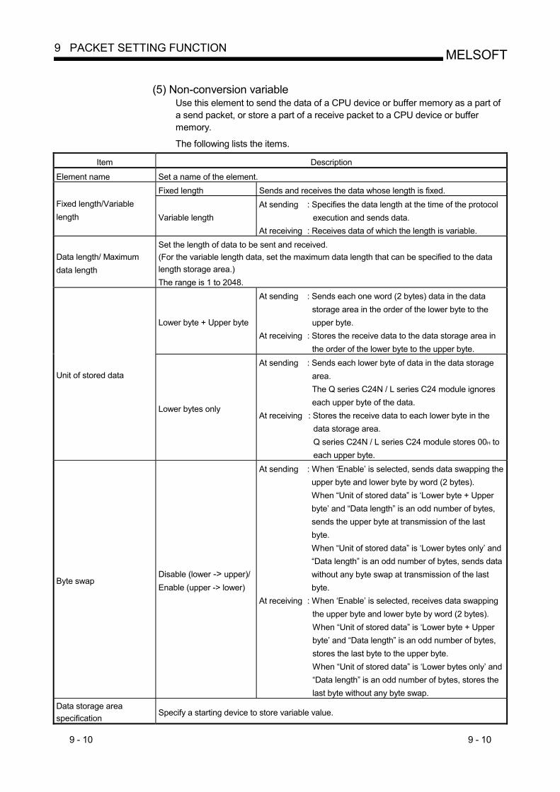
Use this element to send the data of a CPU device or buffer memory as a part of a send packet, or store a part of a receive packet to a CPU device or buffer memory. The following lists the items.
Item Description
Element name Set a name of the element. Fixed length Sends and receives the data whose length is fixed.
Fixed length/Variable length Variable length
At sending : Specifies the data length at the time of the protocol execution and sends data.
At receiving : Receives data of which the length is variable.
Data length/ Maximum data length
Set the length of data to be sent and received. (For the variable length data, set the maximum data length that can be specified to the data length storage area.) The range is 1 to 2048.
Lower byte + Upper byte
At sending : Sends each one word (2 bytes) data in the data storage area in the order of the lower byte to the upper byte.
At receiving : Stores the receive data to the data storage area in the order of the lower byte to the upper byte.
Unit of stored data
Lower bytes only
At sending : Sends each lower byte of data in the data storage area. The Q series C24N / L series C24 module ignores each upper byte of the data.
At receiving : Stores the receive data to each lower byte in the data storage area. Q series C24N / L series C24 module stores 00H to each upper byte.
Byte swap Disable (lower -> upper)/ Enable (upper -> lower)
At sending : When ‘Enable’ is selected, sends data swapping the upper byte and lower byte by word (2 bytes). When “Unit of stored data” is ‘Lower byte + Upper byte’ and “Data length” is an odd number of bytes, sends the upper byte at transmission of the last byte. When “Unit of stored data” is ‘Lower bytes only’ and “Data length” is an odd number of bytes, sends data without any byte swap at transmission of the last byte.
At receiving : When ‘Enable’ is selected, receives data swapping the upper byte and lower byte by word (2 bytes). When “Unit of stored data” is ‘Lower byte + Upper byte’ and “Data length” is an odd number of bytes, stores the last byte to the upper byte. When “Unit of stored data” is ‘Lower bytes only’ and “Data length” is an odd number of bytes, stores the last byte without any byte swap.
Data storage area specification
Specify a starting device to store variable value.
9 - 11 9 - 11
MELSOFT9 PACKET SETTING FUNCTION
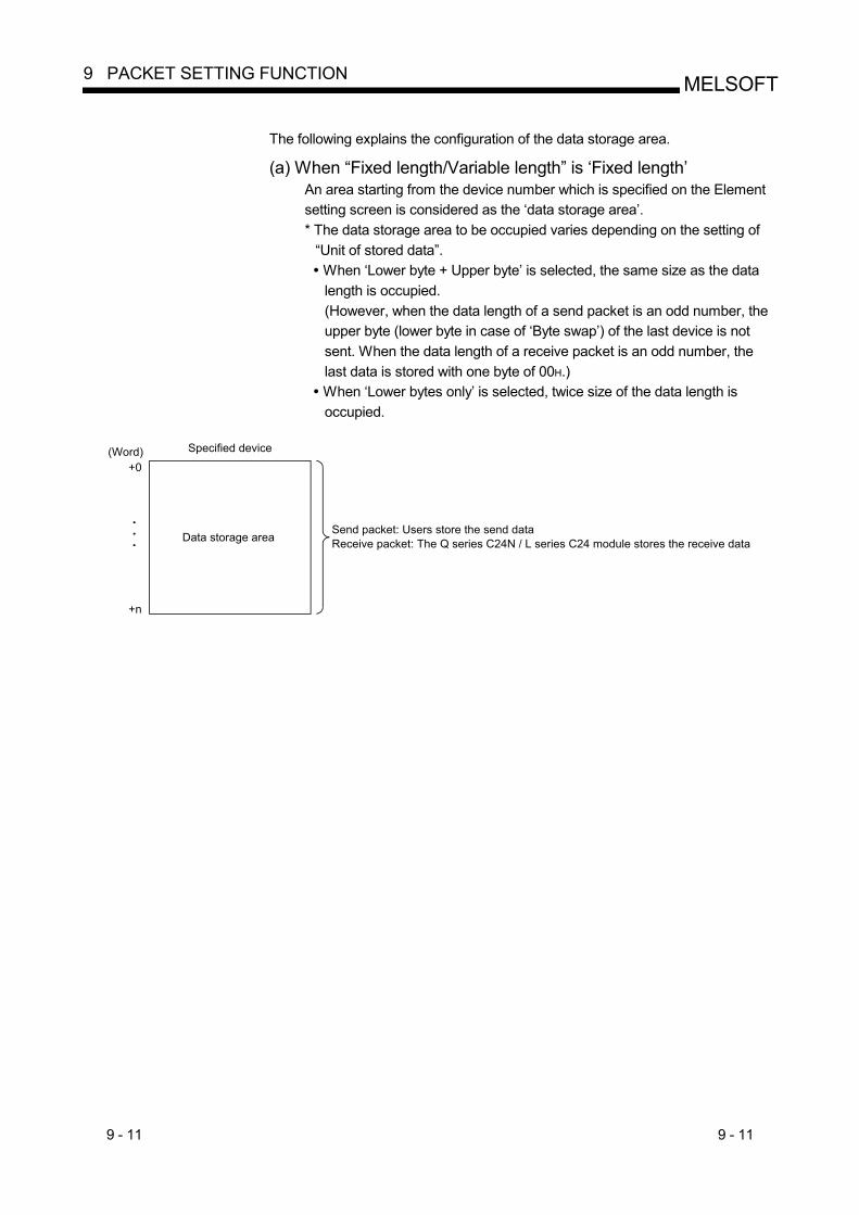
The following explains the configuration of the data storage area.
(a) When “Fixed length/Variable length” is ‘Fixed length’
An area starting from the device number which is specified on the Element setting screen is considered as the ‘data storage area’. * The data storage area to be occupied varies depending on the setting of
“Unit of stored data”. When ‘Lower byte + Upper byte’ is selected, the same size as the data length is occupied. (However, when the data length of a send packet is an odd number, the upper byte (lower byte in case of ‘Byte swap’) of the last device is not sent. When the data length of a receive packet is an odd number, the last data is stored with one byte of 00H.)
When ‘Lower bytes only’ is selected, twice size of the data length is occupied.
Specified device
Data storage area
(Word)+0
+n
Send packet: Users store the send dataReceive packet: The Q series C24N / L series C24 module stores the receive data
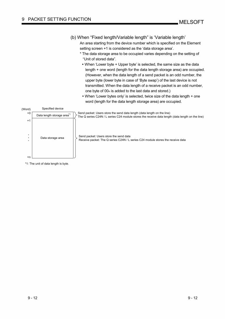
9 - 12 9 - 12
MELSOFT9 PACKET SETTING FUNCTION
(b) When “Fixed length/Variable length” is ‘Variable length’
An area starting from the device number which is specified on the Element setting screen +1 is considered as the ‘data storage area’. * The data storage area to be occupied varies depending on the setting of
“Unit of stored data”. When ‘Lower byte + Upper byte’ is selected, the same size as the data length + one word (length for the data length storage area) are occupied. (However, when the data length of a send packet is an odd number, the upper byte (lower byte in case of ‘Byte swap’) of the last device is not transmitted. When the data length of a receive packet is an odd number, one byte of 00H is added to the last data and stored.)
When ‘Lower bytes only’ is selected, twice size of the data length + one word (length for the data length storage area) are occupied.
+1
+n
Data length storage area*1 Send packet: Users store the send data length (data length on the line)The Q series C24N / L series C24 module stores the receive data length (data length on the line)
*1: The unit of data length is byte.
Data storage area Send packet: Users store the send dataReceive packet: The Q series C24N / L series C24 module stores the receive data
(Word)+0
Specified device
9 - 13 9 - 13
MELSOFT9 PACKET SETTING FUNCTION
When receiving variable length data whose length exceeds the “Maximum data length”, the Q series C24N / L series C24 module stores data as long as the maximum data length and omits the rest. (A protocol completes successfully.)
In receive packet data from other devices, the Q series C24N / L series C24 module needs to be able to discriminate data corresponding to a Non-conversion variable from those of a Terminator or a Static Data following a Non-conversion variable. The receive process may not be performed normally if they cannot be classed. (Example) When value of a Terminator or value of a Static Data following a Non-conversion variable is used in a Non-conversion variable, the Q series C24N / L series C24 module recognizes it as data of a Terminator or a Static Data following a Non-conversion variable and performs the verify/receive process.
Multiple Non-conversion variable (Fixed length) elements can be placed in a packet, and multiple Non-conversion variable (Variable length) elements can also be placed in a send packet. However, only one Non-conversion variable (Variable length) can be placed in a receive packet, and any of the following requirements need to be met. (a) Place any of the following data immediate after a Non-conversion variable
Static Data Terminator Check code + Static Data Check code + Terminator
(b) Place a Length before a Non-conversion variable and include the Non-conversion variable in the calculation range.
In addition, two or more of the following four elements cannot be placed in the same packet.
Conversion variable (Variable number of data) Conversion variable (Fixed number of data and Variable number of digits) (Excluding a case where “Number of data” is ‘1’ and “Delimiter” is not ‘No delimiter’.) Non-conversion variable (Variable length) Non-verified reception (Variable number of characters)
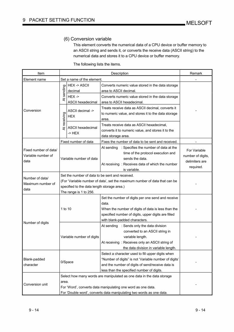
9 - 14 9 - 14
MELSOFT9 PACKET SETTING FUNCTION
(6) Conversion variable
This element converts the numerical data of a CPU device or buffer memory to an ASCII string and sends it, or converts the receive data (ASCII string) to the numerical data and stores it to a CPU device or buffer memory.
The following lists the items.
Item Description Remark
Element name Set a name of the element. - HEX -> ASCII decimal
Converts numeric value stored in the data storage area to ASCII decimal.
At s
endi
ng
HEX -> ASCII hexadecimal
Converts numeric value stored in the data storage area to ASCII hexadecimal.
ASCII decimal -> HEX
Treats receive data as ASCII decimal, converts it to numeric value, and stores it to the data storage area.
Conversion
At re
ceiv
ing
ASCII hexadecimal -> HEX
Treats receive data as ASCII hexadecimal, converts it to numeric value, and stores it to the data storage area.
-
Fixed number of data Fixes the number of data to be sent and received. -
Fixed number of data/ Variable number of data
Variable number of data
At sending : Specifies the number of data at the time of the protocol execution and sends the data.
At receiving : Receives data of which the number is variable.
For Variable number of digits,
delimiters are required.
Number of data/ Maximum number of data
Set the number of data to be sent and received. (For ‘Variable number of data’, set the maximum number of data that can be specified to the data length storage area.) The range is 1 to 256.
-
1 to 10
Set the number of digits per one send and receive data. When the number of digits of data is less than the specified number of digits, upper digits are filled with blank-padded characters.
-
Number of digits
Variable number of digits
At sending : Sends only the data division converted to an ASCII string in variable length.
At receiving : Receives only an ASCII string of the data division in variable length.
-
Blank-padded character
0/Space
Select a character used to fill upper digits when “Number of digits” is not ‘Variable number of digits’ and the number of digits of send/receive data is less than the specified number of digits.
-
Conversion unit
Select how many words are manipulated as one data in the data storage area. For ‘Word’, converts data manipulating one word as one data. For ‘Double word’, converts data manipulating two words as one data.
-
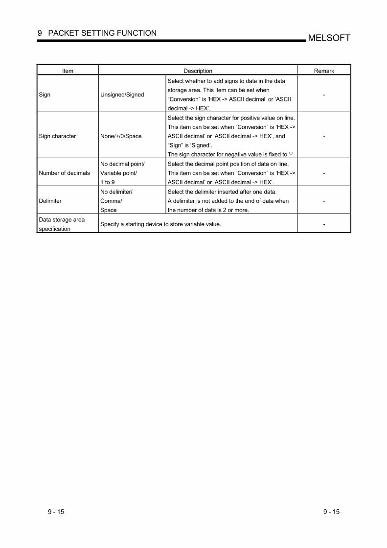
9 - 15 9 - 15
MELSOFT9 PACKET SETTING FUNCTION
Item Description Remark
Sign Unsigned/Signed
Select whether to add signs to date in the data storage area. This item can be set when “Conversion” is ‘HEX -> ASCII decimal’ or ‘ASCII decimal -> HEX’.
-
Sign character None/+/0/Space
Select the sign character for positive value on line. This item can be set when “Conversion” is ‘HEX -> ASCII decimal’ or ‘ASCII decimal -> HEX’, and “Sign” is ‘Signed’. The sign character for negative value is fixed to ‘-‘.
-
Number of decimals No decimal point/ Variable point/ 1 to 9
Select the decimal point position of data on line. This item can be set when “Conversion” is ‘HEX -> ASCII decimal’ or ‘ASCII decimal -> HEX’.
-
Delimiter No delimiter/ Comma/ Space
Select the delimiter inserted after one data. A delimiter is not added to the end of data when the number of data is 2 or more.
-
Data storage area specification
Specify a starting device to store variable value. -
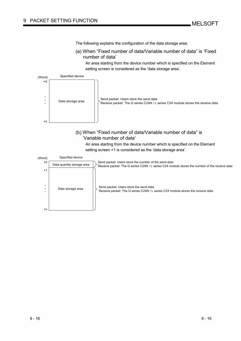
9 - 16 9 - 16
MELSOFT9 PACKET SETTING FUNCTION
The following explains the configuration of the data storage area.
(a) When “Fixed number of data/Variable number of data” is ‘Fixed
number of data’ An area starting from the device number which is specified on the Element setting screen is considered as the ‘data storage area’.
Specified device
Data storage area
(Word)+0
+n
Send packet: Users store the send dataReceive packet: The Q series C24N / L series C24 module stores the receive data
(b) When “Fixed number of data/Variable number of data” is ‘Variable number of data’
An area starting from the device number which is specified on the Element setting screen +1 is considered as the ‘data storage area’.
+1
+n
Data quantity storage areaSend packet: Users store the number of the send dataReceive packet: The Q series C24N / L series C24 module stores the number of the receive data
Data storage area Send packet: Users store the send dataReceive packet: The Q series C24N / L series C24 module stores the receive data
(Word)+0
Specified device
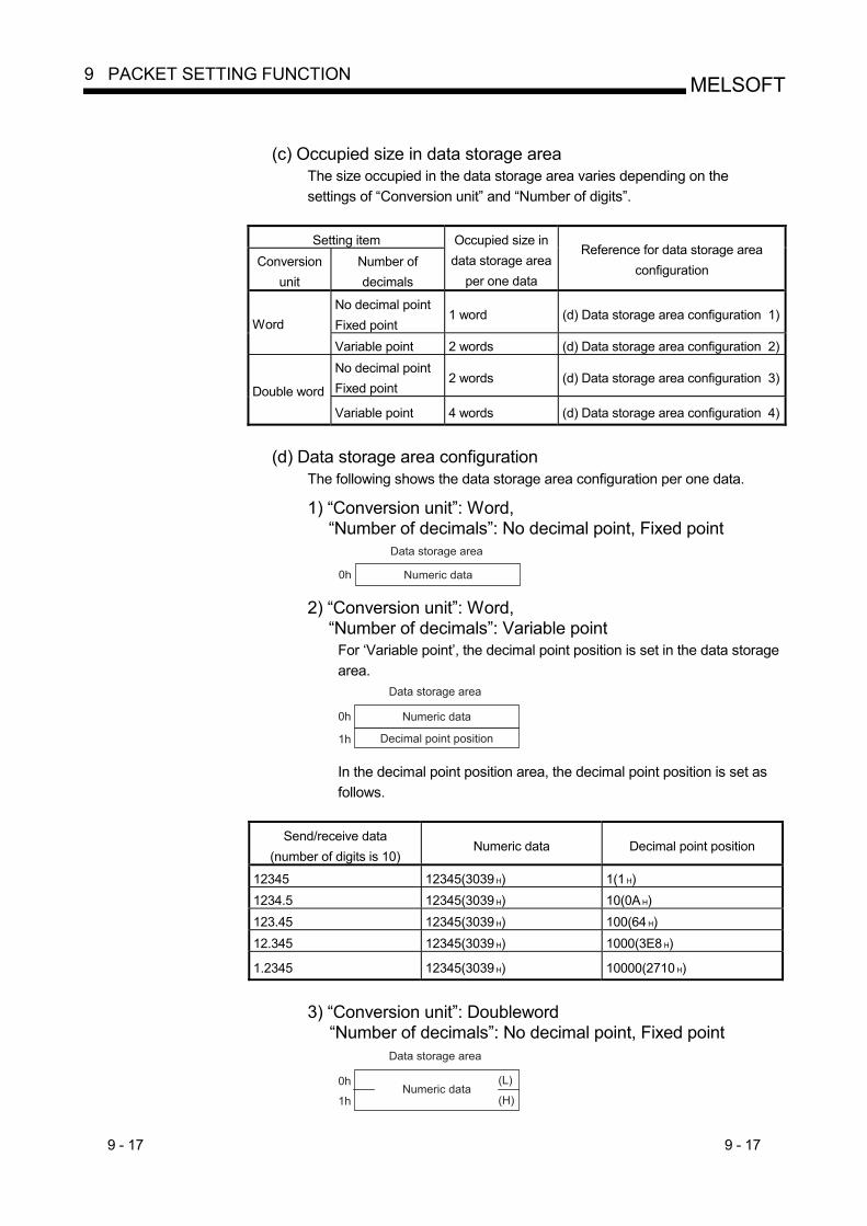
9 - 17 9 - 17
MELSOFT9 PACKET SETTING FUNCTION
(c) Occupied size in data storage area
The size occupied in the data storage area varies depending on the settings of “Conversion unit” and “Number of digits”. Setting item
Conversion unit
Number of decimals
Occupied size in data storage area
per one data
Reference for data storage area configuration
No decimal point Fixed point
1 word (d) Data storage area configuration 1)Word
Variable point 2 words (d) Data storage area configuration 2)No decimal point Fixed point
2 words (d) Data storage area configuration 3)Double word
Variable point 4 words (d) Data storage area configuration 4)
(d) Data storage area configuration
The following shows the data storage area configuration per one data.
1) “Conversion unit”: Word, “Number of decimals”: No decimal point, Fixed point
Data storage area
Numeric data0h 2) “Conversion unit”: Word,
“Number of decimals”: Variable point For ‘Variable point’, the decimal point position is set in the data storage area.
Data storage area
Numeric data
Decimal point position
0h
1h In the decimal point position area, the decimal point position is set as follows.
Send/receive data
(number of digits is 10) Numeric data Decimal point position
12345 12345(3039 H) 1(1 H) 1234.5 12345(3039 H) 10(0A H) 123.45 12345(3039 H) 100(64 H) 12.345 12345(3039 H) 1000(3E8 H)
1.2345 12345(3039 H) 10000(2710 H)
3) “Conversion unit”: Doubleword
“Number of decimals”: No decimal point, Fixed point Data storage area
Numeric data0h
1h
(L)
(H)
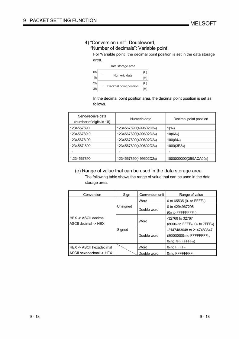
9 - 18 9 - 18
MELSOFT9 PACKET SETTING FUNCTION
4) “Conversion unit”: Doubleword,
“Number of decimals”: Variable point For ‘Variable point’, the decimal point position is set in the data storage area.
Data storage area
Numeric data
Decimal point position
(L)
(H)
(L)
(H)
0h
1h
2h
3h In the decimal point position area, the decimal point position is set as follows.
Send/receive data
(number of digits is 10) Numeric data Decimal point position
1234567890 1234567890(499602D2H) 1(1H) 123456789.0 1234567890(499602D2H) 10(0AH) 12345678.90 1234567890(499602D2H) 100(64H) 1234567.890 1234567890(499602D2H) 1000(3E8H) : : :
1.234567890 1234567890(499602D2H) 1000000000(3B9ACA00H)
(e) Range of value that can be used in the data storage area
The following table shows the range of value that can be used in the data storage area.
Conversion Sign Conversion unit Range of value
Word 0 to 65535 (0H to FFFFH) Unsigned
Double word 0 to 4294967295 (0H to FFFFFFFFH)
Word -32768 to 32767 (8000H to FFFFH, 0H to 7FFFH)
HEX -> ASCII decimal ASCII decimal -> HEX
Signed Double word
-2147483648 to 2147483647 (80000000H to FFFFFFFFH, 0H to 7FFFFFFFH)
Word 0H to FFFFH HEX -> ASCII hexadecimal ASCII hexadecimal -> HEX
Double word 0H to FFFFFFFFH
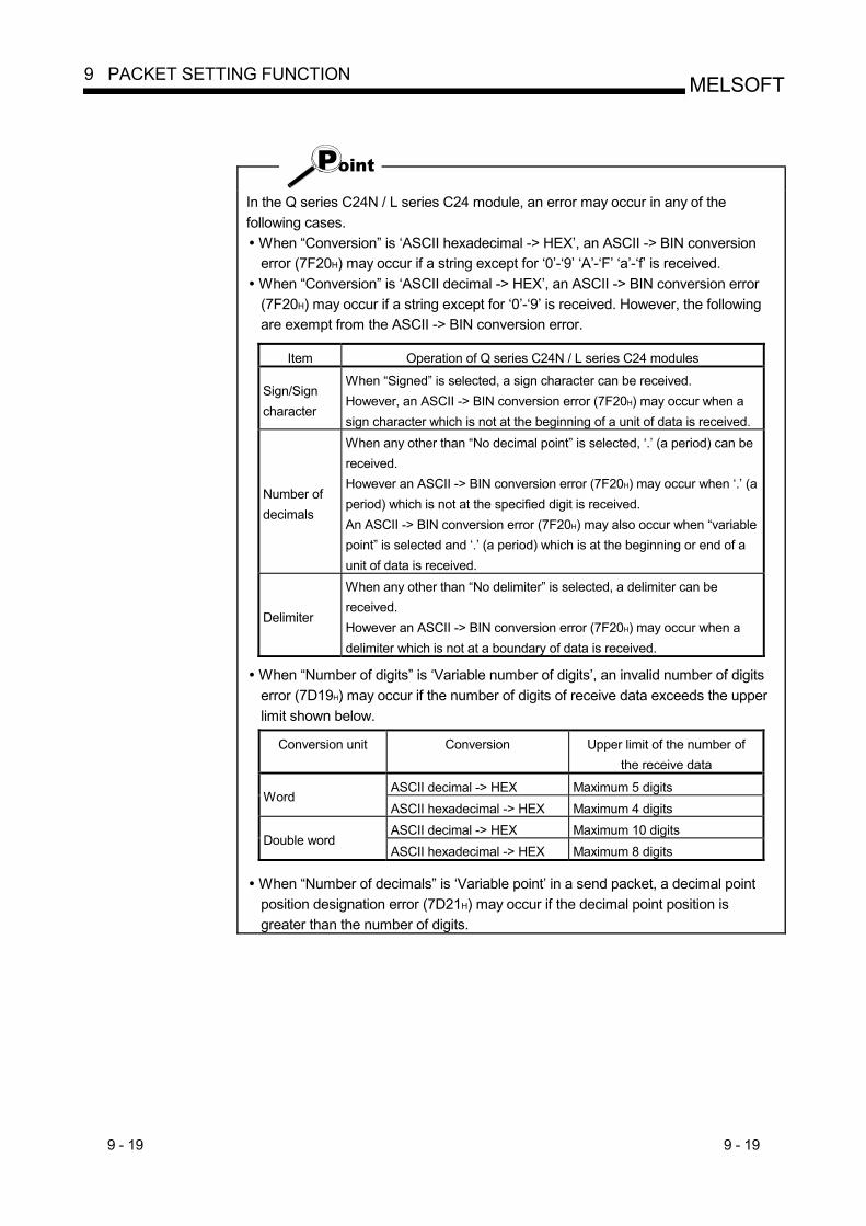
9 - 19 9 - 19
MELSOFT9 PACKET SETTING FUNCTION
In the Q series C24N / L series C24 module, an error may occur in any of the following cases.
When “Conversion” is ‘ASCII hexadecimal -> HEX’, an ASCII -> BIN conversion error (7F20H) may occur if a string except for ‘0’-‘9’ ‘A’-‘F’ ‘a’-‘f’ is received.
When “Conversion” is ‘ASCII decimal -> HEX’, an ASCII -> BIN conversion error (7F20H) may occur if a string except for ‘0’-‘9’ is received. However, the following are exempt from the ASCII -> BIN conversion error.
Item Operation of Q series C24N / L series C24 modules
Sign/Sign character
When “Signed” is selected, a sign character can be received. However, an ASCII -> BIN conversion error (7F20H) may occur when a sign character which is not at the beginning of a unit of data is received.
Number of decimals
When any other than “No decimal point” is selected, ‘.’ (a period) can be received. However an ASCII -> BIN conversion error (7F20H) may occur when ‘.’ (a period) which is not at the specified digit is received. An ASCII -> BIN conversion error (7F20H) may also occur when “variable point” is selected and ‘.’ (a period) which is at the beginning or end of a unit of data is received.
Delimiter
When any other than “No delimiter” is selected, a delimiter can be received. However an ASCII -> BIN conversion error (7F20H) may occur when a delimiter which is not at a boundary of data is received.
When “Number of digits” is ‘Variable number of digits’, an invalid number of digits error (7D19H) may occur if the number of digits of receive data exceeds the upper limit shown below.
Conversion unit Conversion Upper limit of the number of the receive data
ASCII decimal -> HEX Maximum 5 digits Word
ASCII hexadecimal -> HEX Maximum 4 digits ASCII decimal -> HEX Maximum 10 digits
Double word ASCII hexadecimal -> HEX Maximum 8 digits
When “Number of decimals” is ‘Variable point’ in a send packet, a decimal point position designation error (7D21H) may occur if the decimal point position is greater than the number of digits.
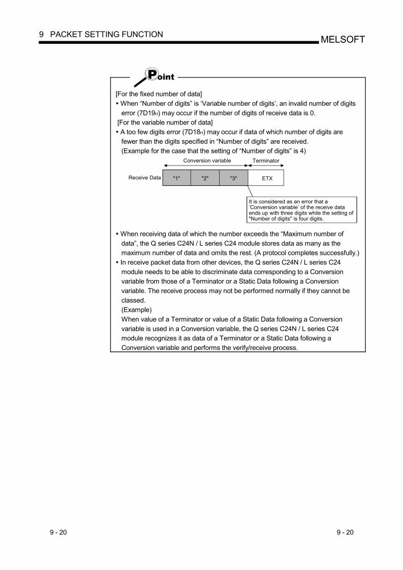
9 - 20 9 - 20
MELSOFT9 PACKET SETTING FUNCTION
[For the fixed number of data] When “Number of digits” is ‘Variable number of digits’, an invalid number of digits error (7D19H) may occur if the number of digits of receive data is 0.
[For the variable number of data] A too few digits error (7D18H) may occur if data of which number of digits are fewer than the digits specified in “Number of digits” are received. (Example for the case that the setting of “Number of digits” is 4)
Receive Data
Conversion variable Terminator
"1" "2" "3" ETX
It is considered as an error that a’Conversion variable’ of the receive dataends up with three digits while the setting of"Number of digits" is four digits.
When receiving data of which the number exceeds the “Maximum number of data”, the Q series C24N / L series C24 module stores data as many as the maximum number of data and omits the rest. (A protocol completes successfully.)
In receive packet data from other devices, the Q series C24N / L series C24 module needs to be able to discriminate data corresponding to a Conversion variable from those of a Terminator or a Static Data following a Conversion variable. The receive process may not be performed normally if they cannot be classed. (Example) When value of a Terminator or value of a Static Data following a Conversion variable is used in a Conversion variable, the Q series C24N / L series C24 module recognizes it as data of a Terminator or a Static Data following a Conversion variable and performs the verify/receive process.
9 - 21 9 - 21
MELSOFT9 PACKET SETTING FUNCTION
To place a Conversion variable in a packet, the following requirements need to be met. (1) To place Conversion variable in send packet
Multiple Conversion variable elements can be placed in one packet, and they can be placed in desired positions in the data division.
(2) To place Conversion variable in receive packet Multiple Conversion variable elements can be placed in one packet in cases other than [Variable number of data] and (a) - 1) of [Fixed number of data].
[Variable number of data] Only one Conversion variable can be placed in one packet, and any of the following 1) and 2) need to be met.
1) For discriminating the data length of a Conversion variable, any of the following items is placed immediate after the Conversion variable.
Static Data Terminator Check code + Static Data Check code + Terminator
2) A ‘Length’ is placed before a Conversion variable. (The Conversion variable needs to be included in the calculating range.)
[Fixed number of data] (a) Variable number of digits
1) When the number of data is 2 or more, or the number of data is 1 with no delimiter, only one Conversion variable can be placed in a packet and it needs to be placed in the order mentioned in [Variable number of data].
2) When a Conversion variable (the number of data is 1, with delimiter, and variable number of digits) and the following four elements are placed in the same packet, these four elements need to be placed behind the Conversion variable (the number of data is 1, with delimiter, and variable number of digits).
Conversion variable (variable number of data) Conversion variable (fixed number of data and variable number of digits)
(The case of (a) – 1. Excluding a case where “Number of data” is ‘1’ and “Delimiter” is not ‘No delimiter’.)
Non-conversion variable (variable length) Non-verified reception (variable number of characters)
Note that two or more of these four elements cannot be placed in the same packet.
(b) Fixed number of digits (1 to 10) 1) When a Conversion variable (variable decimal point) and the four elements
mentioned in (a) – 2), these elements need to be placed behind the Conversion variable (variable decimal point).
2) When a Conversion variable (unsigned) and the four elements mentioned in (a) – 2), these elements need to be placed behind the Conversion variable (unsigned).
9 - 22 9 - 22
MELSOFT9 PACKET SETTING FUNCTION
(7) Check code
Use this element when an element indicating check code data is included in a packet. The Q series C24N / L series C24 module automatically calculates a specified check code at timing of sending/receiving, and adds it to a send packet or detects an error of a receive packet.
The following table lists the items.
Item Description Remark
Element name Set a name of the element. -
Processing method Select a calculating method. Horizontal parity/Sum check/16-bit CRC (for MODBUS)
-
Code type ASCII hexadecimal ASCII decimal HEX
At sending : Select a format in which a calculated check code is sent.
At receiving : Select a format in which data are received.
Not settable when “Processing method”
is ‘16-bit CRC (for MODBUS)’
Data length Select the data length on the line (byte). The range is 1 to 4.
Not settable when “Processing method”
is ‘16-bit CRC (for MODBUS)’
Forward direction (Upper byte -> Lower byte)
At sending : Sends a calculated check code, from the upper byte.
At receiving : Manipulates receive data as a check code, from the upper byte.
Reverse direction (Lower byte -> Upper byte)
At sending : Sends a calculated check code, from the upper byte.
At receiving : Manipulates receive data as a check code, from the upper byte. Effective only if the data length is 2 to 4 (bytes).
Data flow
Byte swap (by word)
At sending : Sends a calculated check code swapping the upper byte and lower byte by word.
At receiving : Manipulates receive data as a check code swapping the upper byte and lower byte by word. Effective only if the data length is 4 bytes.
Not settable when “Processing method”
is ‘16-bit CRC (for MODBUS)’
Complement calculation
Select the complement calculation. No complement calculation/One’s complement/Two's complement
Not settable when “Processing method”
is ‘16-bit CRC (for MODBUS)’
start Select the starting element number of the calculating range. The range is 1 to 32. Calculating
range end
Select the ending element number of the calculating range. The range is 1 to 32.
-
9 - 23 9 - 23
MELSOFT9 PACKET SETTING FUNCTION
When “Code type” is ‘ASCII hexadecimal’, an ASCII -> BIN conversion error (7F20H) may occur if a string except for ‘0’-‘9’ ‘A’-‘F’ ‘a’-‘f’ is received.
When “Code type” is ‘ASCII decimal’, an ASCII -> BIN conversion error (7F20H) may occur if a string except for ‘0’-‘9’ is received.
Only one Check code can be placed in a packet. Packet elements placed behind a Check code cannot be included in the calculating range.
A Check code cannot be included in the calculated range. When a calculated check code (Sum check/Horizontal parity/16-bit CRC) does not match a received check code, a sum check error (7F24H) may occur.
One or more elements are required before a Check code.
9 - 24 9 - 24
MELSOFT9 PACKET SETTING FUNCTION
(8) Non-verified reception
Use this element when receive data include data not needed. The Q series C24N / L series C24 module skips characters as many as the specified number if a receive packet includes a Non-verified reception.
The following table lists the items.
Item Description Remark
Element name Set a name of the element. - 0 (variable number of characters)
Set this item when the number of characters not to be verified varies in each of communication.
Data length 1 to 2048 (specified number of characters)
Set the number of characters not to be verified.
-
When “Data length” is ‘0’, the following requirements need to be met. (1) Only one Non-verified reception can be placed in a packet. (2) Include a Non-verified reception in the calculating range of a Length.
Otherwise, place any of the following data immediate after a Non-verified reception.
Static Data Terminator Check code + Static Data Check code + Terminator
(3) Two or more of the following four elements cannot be placed in the same packet.
Conversion variable (Variable number of data) Conversion variable (Fixed number of data and Variable number of digits) (Excluding a case where “Number of data” is ‘1’ and “Delimiter” is not ‘No delimiter’.) Non-conversion variable (Variable length) Non-verified reception (Variable number of characters)
In receive packet data from other devices, the Q series C24N / L series C24 module needs to be able to discriminate data corresponding to a Non-verified reception from those of a Terminator or a Static Data following a Non-verified reception. The receive process may not be performed normally if they cannot be classed. (Example) When value of a Terminator or value of a Static Data following a Non-verified reception is used in a Non-verified reception, the Q series C24N / L series C24 module recognizes it as data of a Terminator or a Static Data following a Non-verified reception and performs the verify/receive process.
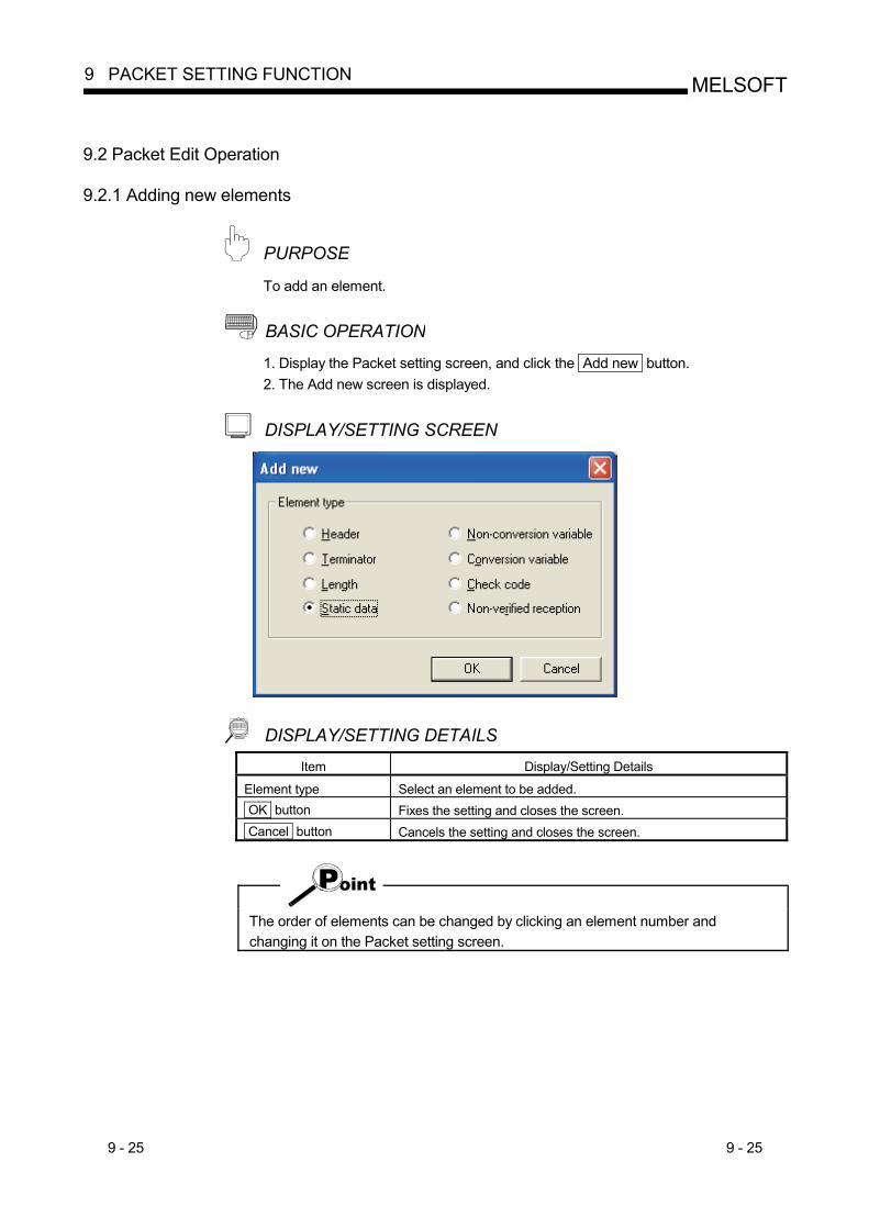
9 - 25 9 - 25
MELSOFT9 PACKET SETTING FUNCTION
9.2 Packet Edit Operation
9.2.1 Adding new elements
PURPOSE To add an element.
BASIC OPERATION 1. Display the Packet setting screen, and click the Add new button. 2. The Add new screen is displayed.
DISPLAY/SETTING SCREEN
DISPLAY/SETTING DETAILS Item Display/Setting Details
Element type Select an element to be added. OK button Fixes the setting and closes the screen. Cancel button Cancels the setting and closes the screen.
The order of elements can be changed by clicking an element number and changing it on the Packet setting screen.
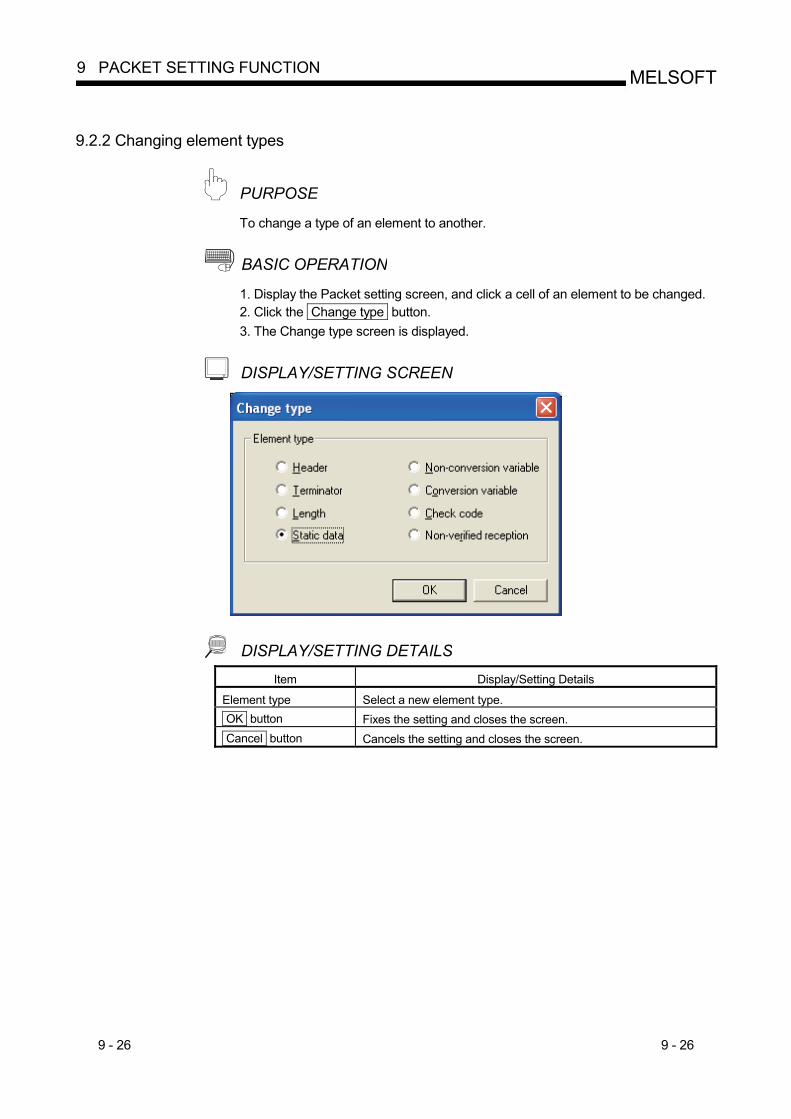
9 - 26 9 - 26
MELSOFT9 PACKET SETTING FUNCTION
9.2.2 Changing element types
PURPOSE To change a type of an element to another.
BASIC OPERATION 1. Display the Packet setting screen, and click a cell of an element to be changed. 2. Click the Change type button. 3. The Change type screen is displayed.
DISPLAY/SETTING SCREEN
DISPLAY/SETTING DETAILS Item Display/Setting Details
Element type Select a new element type. OK button Fixes the setting and closes the screen. Cancel button Cancels the setting and closes the screen.
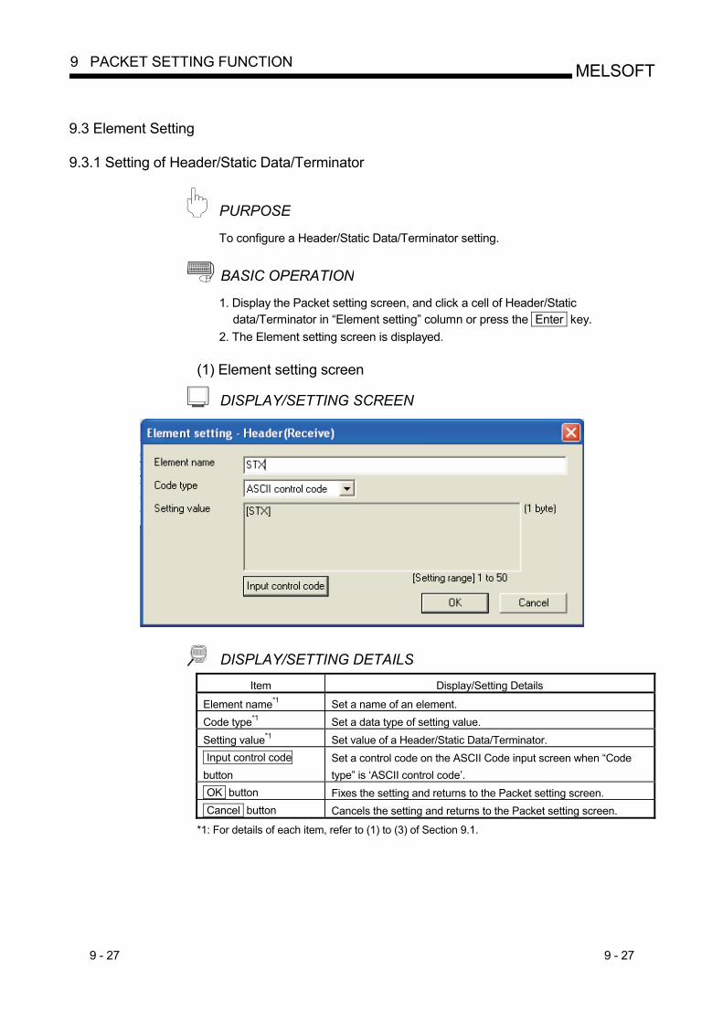
9 - 27 9 - 27
MELSOFT9 PACKET SETTING FUNCTION
9.3 Element Setting
9.3.1 Setting of Header/Static Data/Terminator
PURPOSE To configure a Header/Static Data/Terminator setting.
BASIC OPERATION 1. Display the Packet setting screen, and click a cell of Header/Static
data/Terminator in “Element setting” column or press the Enter key. 2. The Element setting screen is displayed.
(1) Element setting screen
DISPLAY/SETTING SCREEN
DISPLAY/SETTING DETAILS Item Display/Setting Details
Element name*1 Set a name of an element. Code type*1 Set a data type of setting value. Setting value*1 Set value of a Header/Static Data/Terminator. Input control code button
Set a control code on the ASCII Code input screen when “Code type” is ‘ASCII control code’.
OK button Fixes the setting and returns to the Packet setting screen. Cancel button Cancels the setting and returns to the Packet setting screen.
*1: For details of each item, refer to (1) to (3) of Section 9.1.
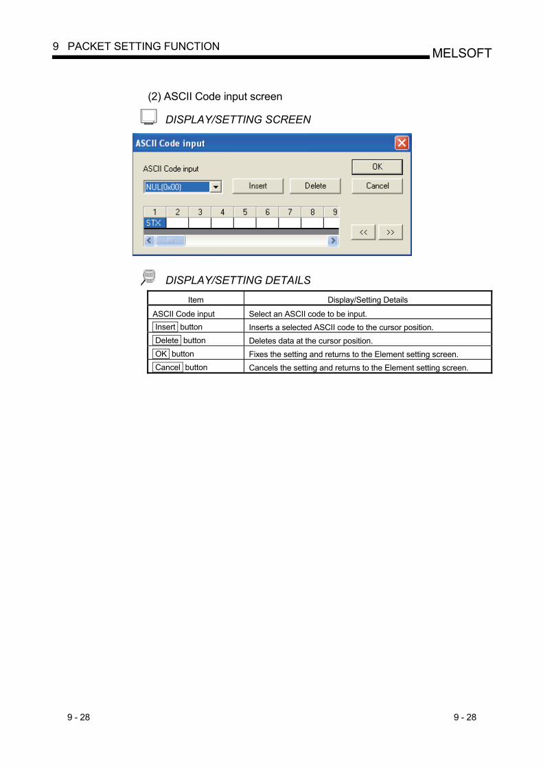
9 - 28 9 - 28
MELSOFT9 PACKET SETTING FUNCTION
(2) ASCII Code input screen
DISPLAY/SETTING SCREEN
DISPLAY/SETTING DETAILS Item Display/Setting Details
ASCII Code input Select an ASCII code to be input. Insert button Inserts a selected ASCII code to the cursor position. Delete button Deletes data at the cursor position. OK button Fixes the setting and returns to the Element setting screen. Cancel button Cancels the setting and returns to the Element setting screen.
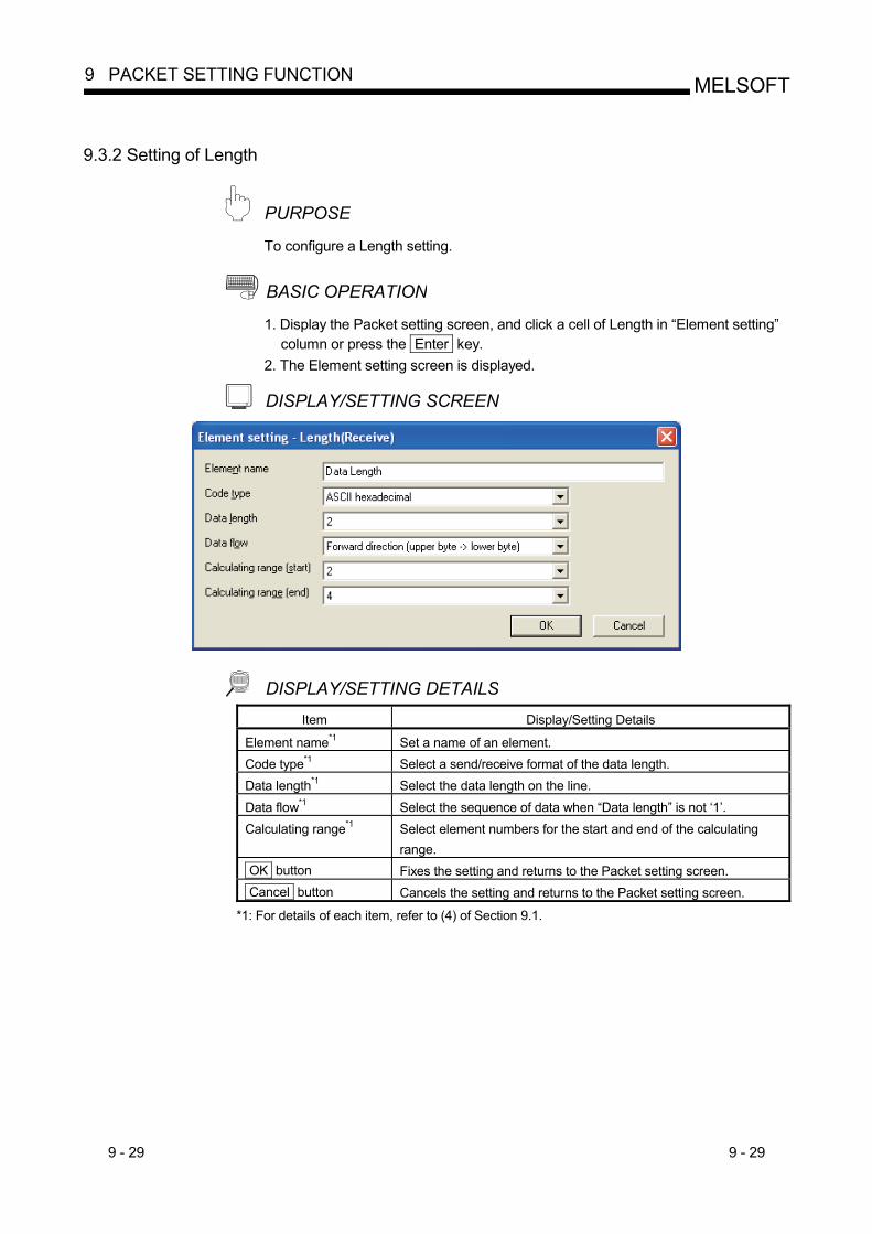
9 - 29 9 - 29
MELSOFT9 PACKET SETTING FUNCTION
9.3.2 Setting of Length
PURPOSE To configure a Length setting.
BASIC OPERATION 1. Display the Packet setting screen, and click a cell of Length in “Element setting”
column or press the Enter key. 2. The Element setting screen is displayed.
DISPLAY/SETTING SCREEN
DISPLAY/SETTING DETAILS Item Display/Setting Details
Element name*1 Set a name of an element. Code type*1 Select a send/receive format of the data length. Data length*1 Select the data length on the line. Data flow*1 Select the sequence of data when “Data length” is not ‘1’. Calculating range*1 Select element numbers for the start and end of the calculating
range. OK button Fixes the setting and returns to the Packet setting screen. Cancel button Cancels the setting and returns to the Packet setting screen.
*1: For details of each item, refer to (4) of Section 9.1.
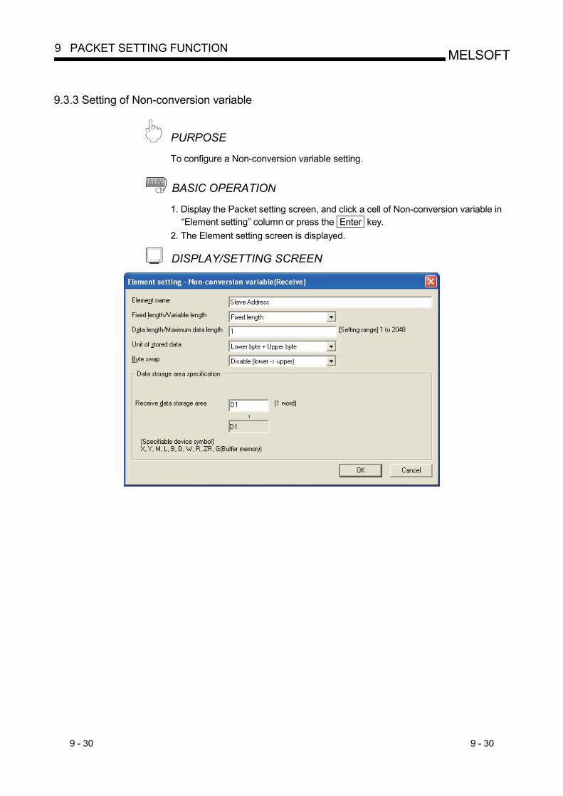
9 - 30 9 - 30
MELSOFT9 PACKET SETTING FUNCTION
9.3.3 Setting of Non-conversion variable
PURPOSE To configure a Non-conversion variable setting.
BASIC OPERATION 1. Display the Packet setting screen, and click a cell of Non-conversion variable in
“Element setting” column or press the Enter key. 2. The Element setting screen is displayed.
DISPLAY/SETTING SCREEN
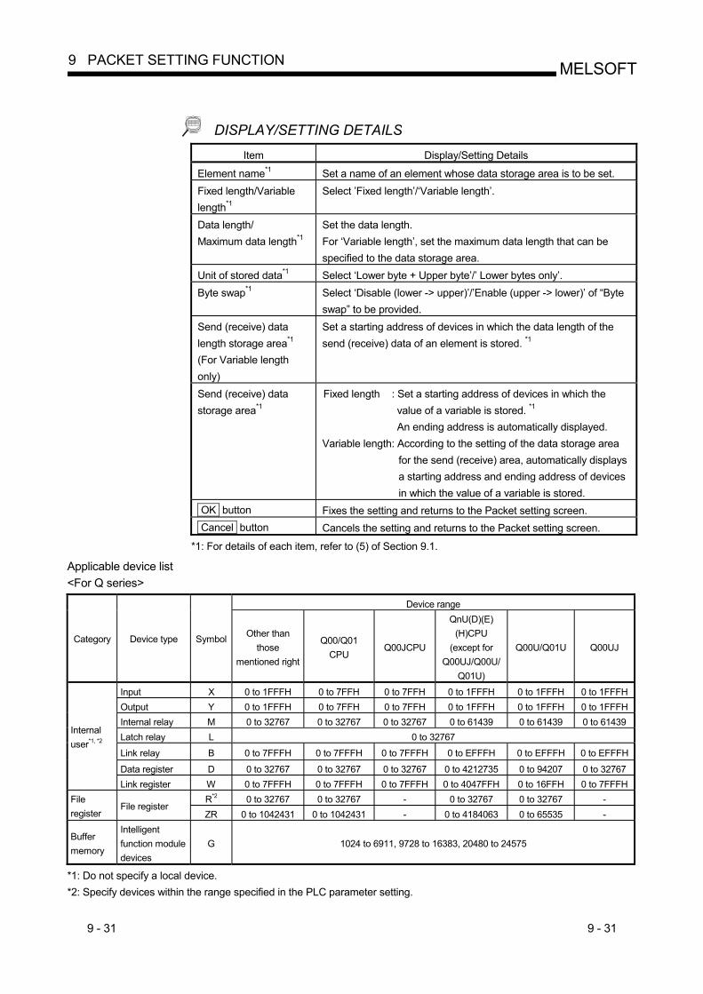
9 - 31 9 - 31
MELSOFT9 PACKET SETTING FUNCTION
DISPLAY/SETTING DETAILS Item Display/Setting Details
Element name*1 Set a name of an element whose data storage area is to be set. Fixed length/Variable length*1
Select ’Fixed length’/‘Variable length’.
Data length/ Maximum data length*1
Set the data length. For ‘Variable length’, set the maximum data length that can be specified to the data storage area.
Unit of stored data*1 Select ‘Lower byte + Upper byte’/’ Lower bytes only’. Byte swap*1 Select ‘Disable (lower -> upper)’/’Enable (upper -> lower)’ of “Byte
swap” to be provided. Send (receive) data length storage area*1 (For Variable length only)
Set a starting address of devices in which the data length of the send (receive) data of an element is stored. *1
Send (receive) data storage area*1
Fixed length : Set a starting address of devices in which the value of a variable is stored. *1 An ending address is automatically displayed.
Variable length: According to the setting of the data storage area for the send (receive) area, automatically displays a starting address and ending address of devices in which the value of a variable is stored.
OK button Fixes the setting and returns to the Packet setting screen. Cancel button Cancels the setting and returns to the Packet setting screen.
*1: For details of each item, refer to (5) of Section 9.1. Applicable device list <For Q series>
Device range
Category Device type Symbol Other than those
mentioned right
Q00/Q01 CPU
Q00JCPU
QnU(D)(E) (H)CPU
(except for Q00UJ/Q00U/
Q01U)
Q00U/Q01U Q00UJ
Input X 0 to 1FFFH 0 to 7FFH 0 to 7FFH 0 to 1FFFH 0 to 1FFFH 0 to 1FFFH Output Y 0 to 1FFFH 0 to 7FFH 0 to 7FFH 0 to 1FFFH 0 to 1FFFH 0 to 1FFFH Internal relay M 0 to 32767 0 to 32767 0 to 32767 0 to 61439 0 to 61439 0 to 61439 Latch relay L 0 to 32767
Link relay B 0 to 7FFFH 0 to 7FFFH 0 to 7FFFH 0 to EFFFH 0 to EFFFH 0 to EFFFH
Data register D 0 to 32767 0 to 32767 0 to 32767 0 to 4212735 0 to 94207 0 to 32767
Internal user*1, *2
Link register W 0 to 7FFFH 0 to 7FFFH 0 to 7FFFH 0 to 4047FFH 0 to 16FFH 0 to 7FFFH R*2 0 to 32767 0 to 32767 - 0 to 32767 0 to 32767 - File
register File register
ZR 0 to 1042431 0 to 1042431 - 0 to 4184063 0 to 65535 -
Buffer memory
Intelligent function module devices
G 1024 to 6911, 9728 to 16383, 20480 to 24575
*1: Do not specify a local device. *2: Specify devices within the range specified in the PLC parameter setting.
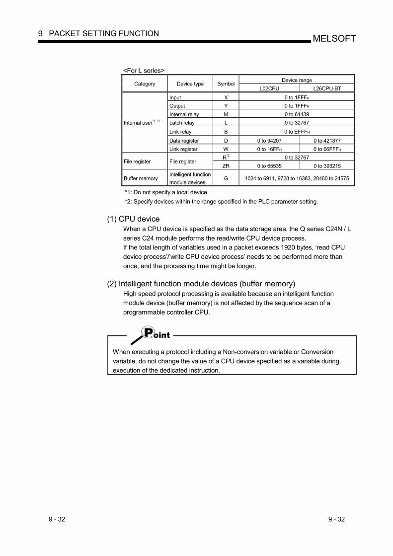
9 - 32 9 - 32
MELSOFT9 PACKET SETTING FUNCTION
<For L series>
Device range Category Device type Symbol
L02CPU L26CPU-BT
Input X 0 to 1FFFH Output Y 0 to 1FFFH Internal relay M 0 to 61439 Latch relay L 0 to 32767
Link relay B 0 to EFFFH
Data register D 0 to 94207 0 to 421877
Internal user*1, *2
Link register W 0 to 16FFH 0 to 66FFFH R*2 0 to 32767
File register File register ZR 0 to 65535 0 to 393215
Buffer memory Intelligent function module devices
G 1024 to 6911, 9728 to 16383, 20480 to 24575
*1: Do not specify a local device. *2: Specify devices within the range specified in the PLC parameter setting.
(1) CPU device
When a CPU device is specified as the data storage area, the Q series C24N / L series C24 module performs the read/write CPU device process. If the total length of variables used in a packet exceeds 1920 bytes, ‘read CPU device process’/’write CPU device process’ needs to be performed more than once, and the processing time might be longer.
(2) Intelligent function module devices (buffer memory) High speed protocol processing is available because an intelligent function module device (buffer memory) is not affected by the sequence scan of a programmable controller CPU.
When executing a protocol including a Non-conversion variable or Conversion variable, do not change the value of a CPU device specified as a variable during execution of the dedicated instruction.
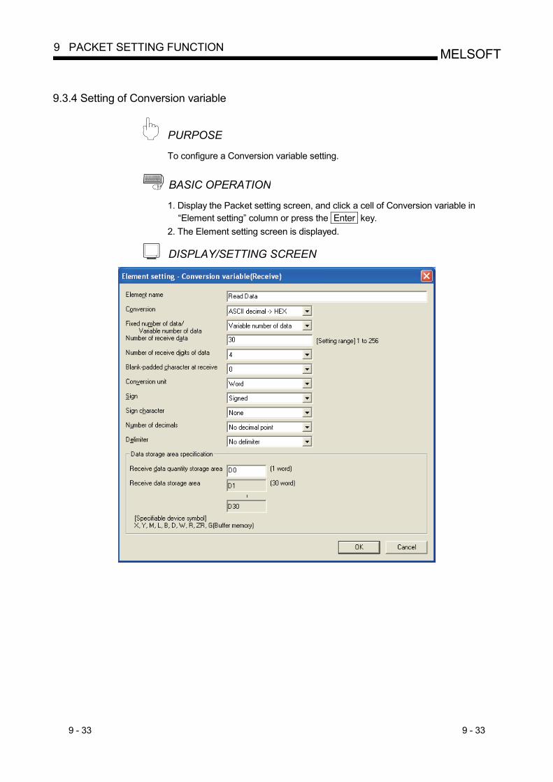
9 - 33 9 - 33
MELSOFT9 PACKET SETTING FUNCTION
9.3.4 Setting of Conversion variable
PURPOSE To configure a Conversion variable setting.
BASIC OPERATION 1. Display the Packet setting screen, and click a cell of Conversion variable in
“Element setting” column or press the Enter key. 2. The Element setting screen is displayed.
DISPLAY/SETTING SCREEN
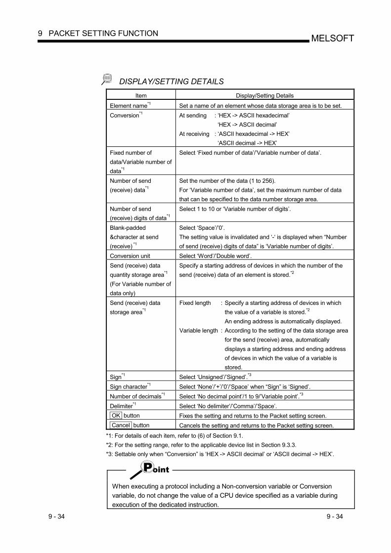
9 - 34 9 - 34
MELSOFT9 PACKET SETTING FUNCTION
DISPLAY/SETTING DETAILS Item Display/Setting Details
Element name*1 Set a name of an element whose data storage area is to be set. Conversion*1 At sending : ‘HEX -> ASCII hexadecimal’
‘HEX -> ASCII decimal’ At receiving : ‘ASCII hexadecimal -> HEX’
‘ASCII decimal -> HEX’ Fixed number of data/Variable number of data*1
Select ‘Fixed number of data’/’Variable number of data’.
Number of send (receive) data*1
Set the number of the data (1 to 256). For ‘Variable number of data’, set the maximum number of data that can be specified to the data number storage area.
Number of send (receive) digits of data*1
Select 1 to 10 or ‘Variable number of digits’.
Blank-padded &character at send (receive) *1
Select ‘Space’/’0’. The setting value is invalidated and ‘-‘ is displayed when “Number of send (receive) digits of data” is ‘Variable number of digits’.
Conversion unit Select ‘Word’/’Double word’. Send (receive) data quantity storage area*1 (For Variable number of data only)
Specify a starting address of devices in which the number of the send (receive) data of an element is stored.*2
Send (receive) data storage area*1
Fixed length : Specify a starting address of devices in which the value of a variable is stored.*2 An ending address is automatically displayed.
Variable length : According to the setting of the data storage area for the send (receive) area, automatically displays a starting address and ending address of devices in which the value of a variable is stored.
Sign*1 Select ‘Unsigned’/’Signed’.*3 Sign character*1 Select ‘None’/’+’/’0’/’Space’ when “Sign” is ‘Signed’. Number of decimals*1 Select ‘No decimal point’/1 to 9/’Variable point’.*3 Delimiter*1 Select ‘No delimiter’/’Comma’/’Space’. OK button Fixes the setting and returns to the Packet setting screen. Cancel button Cancels the setting and returns to the Packet setting screen.
*1: For details of each item, refer to (6) of Section 9.1. *2: For the setting range, refer to the applicable device list in Section 9.3.3. *3: Settable only when “Conversion” is ‘HEX -> ASCII decimal’ or ‘ASCII decimal -> HEX’.
When executing a protocol including a Non-conversion variable or Conversion variable, do not change the value of a CPU device specified as a variable during execution of the dedicated instruction.
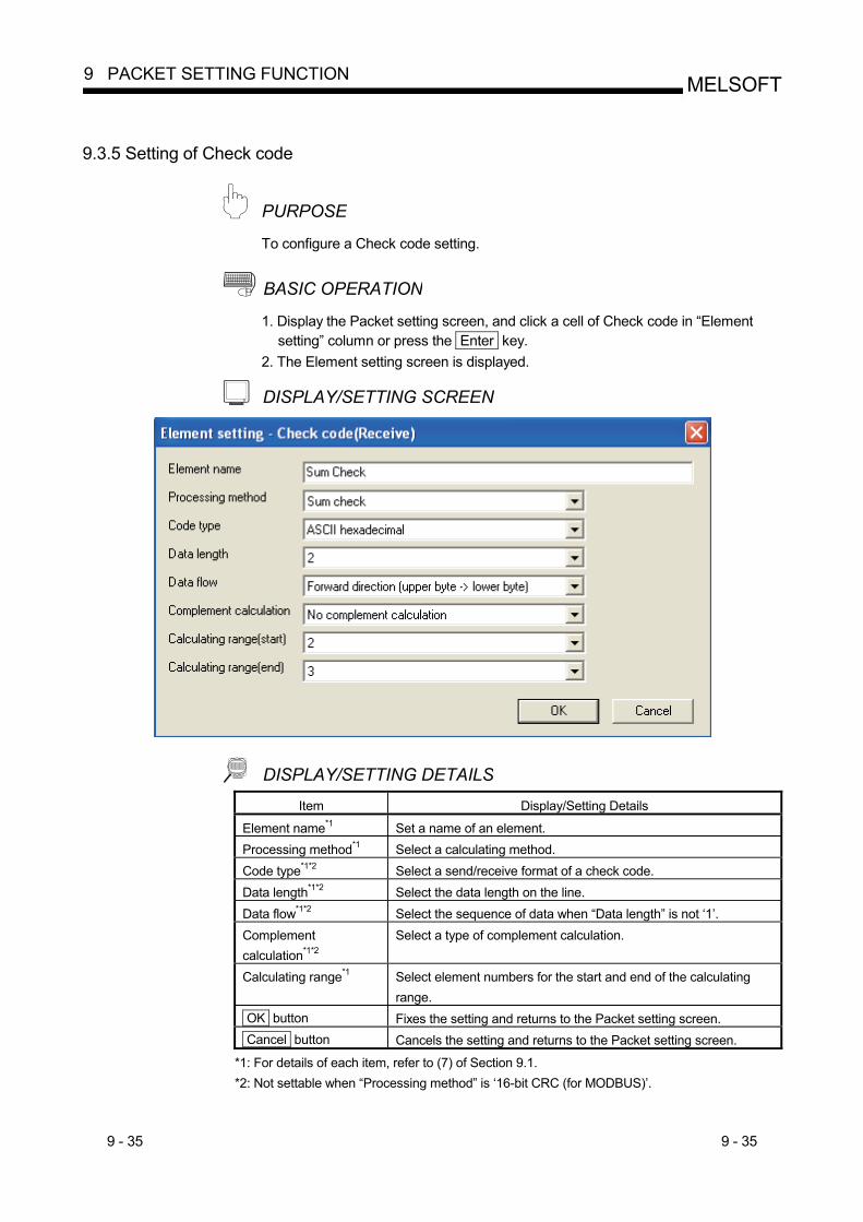
9 - 35 9 - 35
MELSOFT9 PACKET SETTING FUNCTION
9.3.5 Setting of Check code
PURPOSE To configure a Check code setting.
BASIC OPERATION 1. Display the Packet setting screen, and click a cell of Check code in “Element
setting” column or press the Enter key. 2. The Element setting screen is displayed.
DISPLAY/SETTING SCREEN
DISPLAY/SETTING DETAILS Item Display/Setting Details
Element name*1 Set a name of an element. Processing method*1 Select a calculating method. Code type*1*2 Select a send/receive format of a check code. Data length*1*2 Select the data length on the line. Data flow*1*2 Select the sequence of data when “Data length” is not ‘1’. Complement calculation*1*2
Select a type of complement calculation.
Calculating range*1 Select element numbers for the start and end of the calculating range.
OK button Fixes the setting and returns to the Packet setting screen. Cancel button Cancels the setting and returns to the Packet setting screen.
*1: For details of each item, refer to (7) of Section 9.1. *2: Not settable when “Processing method” is ‘16-bit CRC (for MODBUS)’.
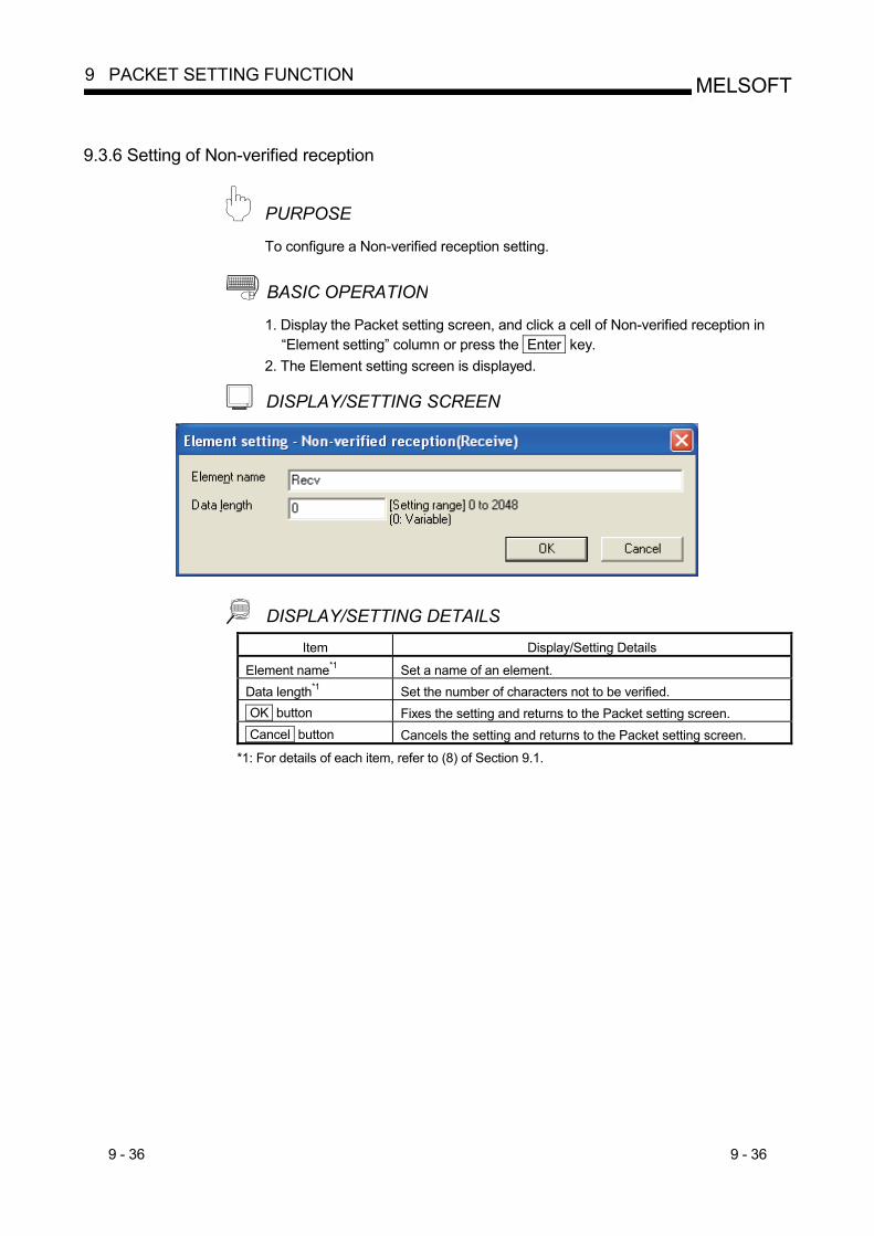
9 - 36 9 - 36
MELSOFT9 PACKET SETTING FUNCTION
9.3.6 Setting of Non-verified reception
PURPOSE To configure a Non-verified reception setting.
BASIC OPERATION 1. Display the Packet setting screen, and click a cell of Non-verified reception in
“Element setting” column or press the Enter key. 2. The Element setting screen is displayed.
DISPLAY/SETTING SCREEN
DISPLAY/SETTING DETAILS Item Display/Setting Details
Element name*1 Set a name of an element. Data length*1 Set the number of characters not to be verified. OK button Fixes the setting and returns to the Packet setting screen. Cancel button Cancels the setting and returns to the Packet setting screen.
*1: For details of each item, refer to (8) of Section 9.1.
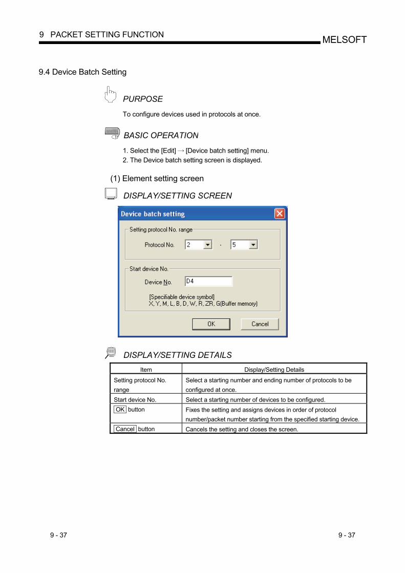
9 - 37 9 - 37
MELSOFT9 PACKET SETTING FUNCTION
9.4 Device Batch Setting
PURPOSE To configure devices used in protocols at once.
BASIC OPERATION 1. Select the [Edit] [Device batch setting] menu. 2. The Device batch setting screen is displayed.
(1) Element setting screen
DISPLAY/SETTING SCREEN
DISPLAY/SETTING DETAILS Item Display/Setting Details
Setting protocol No. range
Select a starting number and ending number of protocols to be configured at once.
Start device No. Select a starting number of devices to be configured. OK button Fixes the setting and assigns devices in order of protocol
number/packet number starting from the specified starting device. Cancel button Cancels the setting and closes the screen.
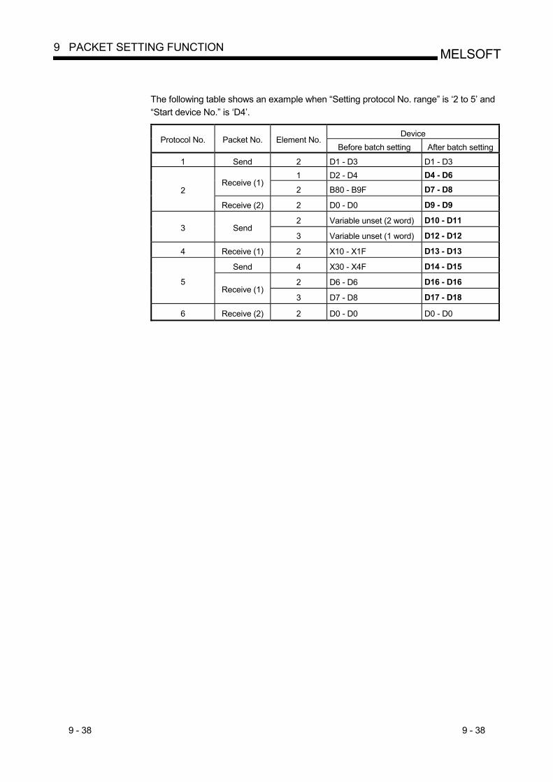
9 - 38 9 - 38
MELSOFT9 PACKET SETTING FUNCTION
The following table shows an example when “Setting protocol No. range” is ‘2 to 5’ and “Start device No.” is ‘D4’.
Device
Protocol No. Packet No. Element No. Before batch setting After batch setting
1 Send 2 D1 - D3 D1 - D3 1 D2 - D4 D4 - D6
Receive (1) 2 B80 - B9F D7 - D8 2
Receive (2) 2 D0 - D0 D9 - D9
2 Variable unset (2 word) D10 - D11 3 Send
3 Variable unset (1 word) D12 - D12
4 Receive (1) 2 X10 - X1F D13 - D13
Send 4 X30 - X4F D14 - D15
2 D6 - D6 D16 - D16 5 Receive (1)
3 D7 - D8 D17 - D18
6 Receive (2) 2 D0 - D0 D0 - D0
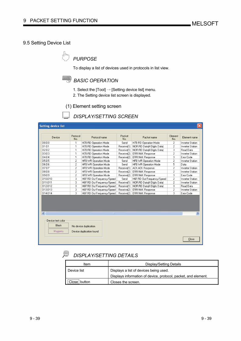
9 - 39 9 - 39
MELSOFT9 PACKET SETTING FUNCTION
9.5 Setting Device List
PURPOSE To display a list of devices used in protocols in list view.
BASIC OPERATION 1. Select the [Tool] [Setting device list] menu. 2. The Setting device list screen is displayed.
(1) Element setting screen
DISPLAY/SETTING SCREEN
DISPLAY/SETTING DETAILS Item Display/Setting Details
Device list Displays a list of devices being used. Displays information of device, protocol, packet, and element.
Close button Closes the screen.
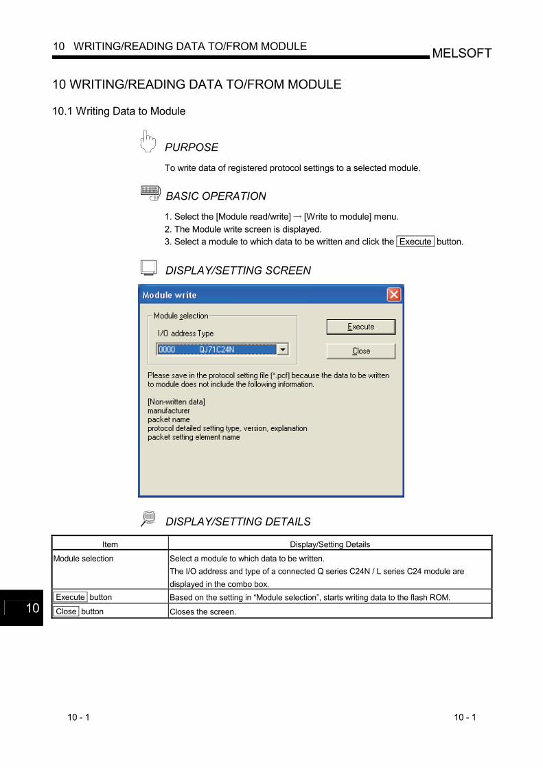
10 - 1 10 - 1
MELSOFT10 WRITING/READING DATA TO/FROM MODULE
10 WRITING/READING DATA TO/FROM MODULE
10.1 Writing Data to Module
PURPOSE To write data of registered protocol settings to a selected module.
BASIC OPERATION 1. Select the [Module read/write] [Write to module] menu. 2. The Module write screen is displayed. 3. Select a module to which data to be written and click the Execute button.
DISPLAY/SETTING SCREEN
DISPLAY/SETTING DETAILS Item Display/Setting Details
Module selection Select a module to which data to be written. The I/O address and type of a connected Q series C24N / L series C24 module are displayed in the combo box.
Execute button Based on the setting in “Module selection”, starts writing data to the flash ROM.
Close button Closes the screen.
10
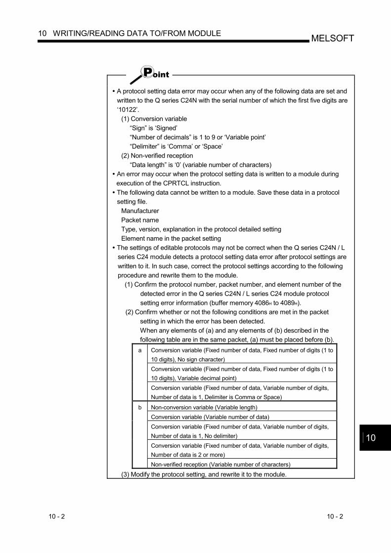
10 - 2 10 - 2
MELSOFT10 WRITING/READING DATA TO/FROM MODULE
A protocol setting data error may occur when any of the following data are set and written to the Q series C24N with the serial number of which the first five digits are ‘10122’.
(1) Conversion variable “Sign” is ‘Signed’ “Number of decimals” is 1 to 9 or ‘Variable point’ “Delimiter” is ‘Comma’ or ‘Space’
(2) Non-verified reception “Data length” is ‘0’ (variable number of characters)
An error may occur when the protocol setting data is written to a module during execution of the CPRTCL instruction. The following data cannot be written to a module. Save these data in a protocol setting file.
Manufacturer Packet name Type, version, explanation in the protocol detailed setting Element name in the packet setting
The settings of editable protocols may not be correct when the Q series C24N / L series C24 module detects a protocol setting data error after protocol settings are written to it. In such case, correct the protocol settings according to the following procedure and rewrite them to the module.
(1) Confirm the protocol number, packet number, and element number of the detected error in the Q series C24N / L series C24 module protocol setting error information (buffer memory 4086H to 4089H).
(2) Confirm whether or not the following conditions are met in the packet setting in which the error has been detected. When any elements of (a) and any elements of (b) described in the following table are in the same packet, (a) must be placed before (b).
Conversion variable (Fixed number of data, Fixed number of digits (1 to 10 digits), No sign character) Conversion variable (Fixed number of data, Fixed number of digits (1 to 10 digits), Variable decimal point)
a
Conversion variable (Fixed number of data, Variable number of digits, Number of data is 1, Delimiter is Comma or Space)
Non-conversion variable (Variable length) Conversion variable (Variable number of data) Conversion variable (Fixed number of data, Variable number of digits, Number of data is 1, No delimiter) Conversion variable (Fixed number of data, Variable number of digits, Number of data is 2 or more)
b
Non-verified reception (Variable number of characters)
(3) Modify the protocol setting, and rewrite it to the module.
10
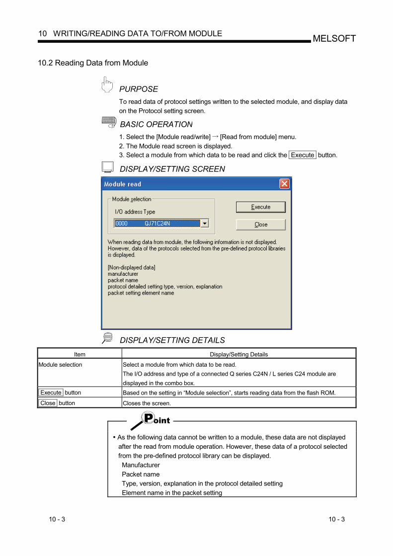
10 - 3 10 - 3
MELSOFT10 WRITING/READING DATA TO/FROM MODULE
10.2 Reading Data from Module
PURPOSE To read data of protocol settings written to the selected module, and display data on the Protocol setting screen. BASIC OPERATION 1. Select the [Module read/write] [Read from module] menu. 2. The Module read screen is displayed. 3. Select a module from which data to be read and click the Execute button. DISPLAY/SETTING SCREEN
DISPLAY/SETTING DETAILS
Item Display/Setting Details
Module selection Select a module from which data to be read. The I/O address and type of a connected Q series C24N / L series C24 module are displayed in the combo box.
Execute button Based on the setting in “Module selection”, starts reading data from the flash ROM.
Close button Closes the screen.
As the following data cannot be written to a module, these data are not displayed after the read from module operation. However, these data of a protocol selected from the pre-defined protocol library can be displayed. Manufacturer Packet name Type, version, explanation in the protocol detailed setting Element name in the packet setting
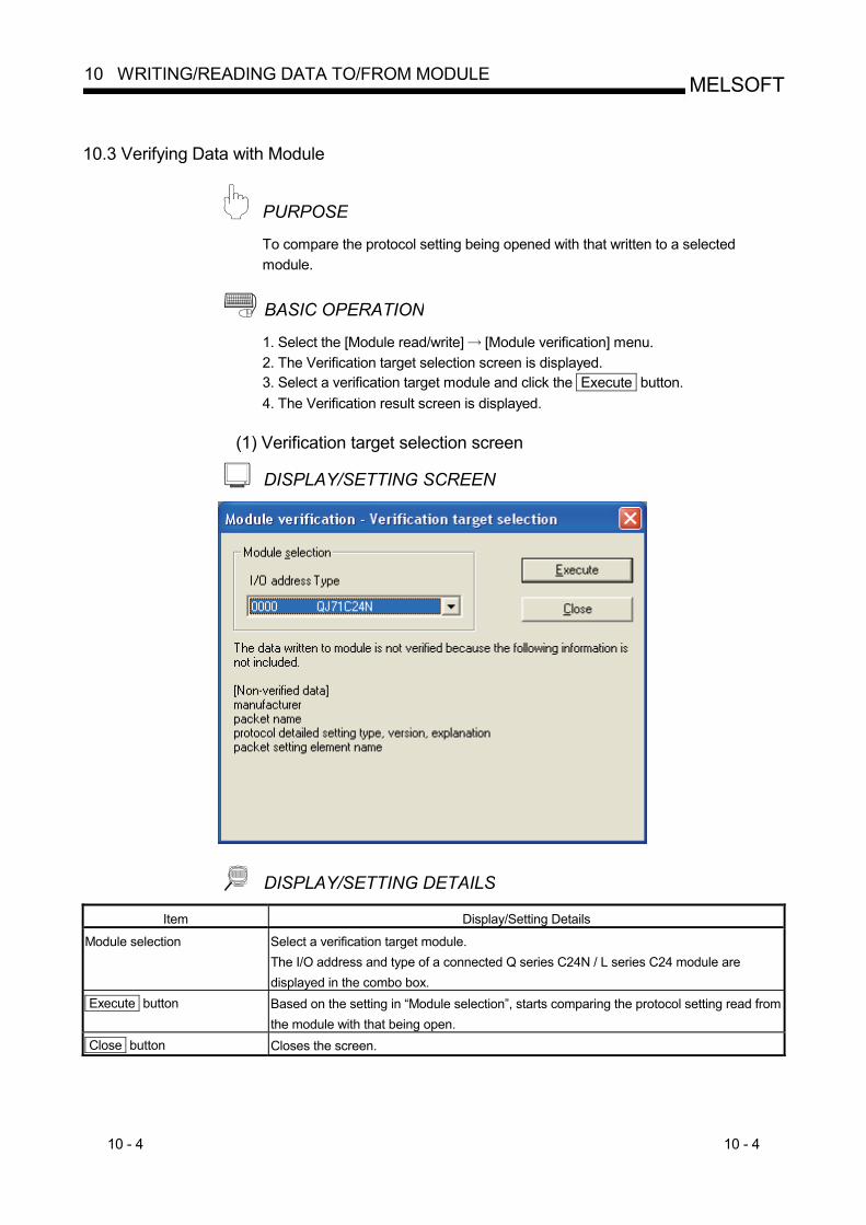
10 - 4 10 - 4
MELSOFT10 WRITING/READING DATA TO/FROM MODULE
10.3 Verifying Data with Module
PURPOSE To compare the protocol setting being opened with that written to a selected module.
BASIC OPERATION 1. Select the [Module read/write] [Module verification] menu. 2. The Verification target selection screen is displayed. 3. Select a verification target module and click the Execute button. 4. The Verification result screen is displayed.
(1) Verification target selection screen
DISPLAY/SETTING SCREEN
DISPLAY/SETTING DETAILS Item Display/Setting Details
Module selection Select a verification target module. The I/O address and type of a connected Q series C24N / L series C24 module are displayed in the combo box.
Execute button Based on the setting in “Module selection”, starts comparing the protocol setting read from the module with that being open.
Close button Closes the screen.
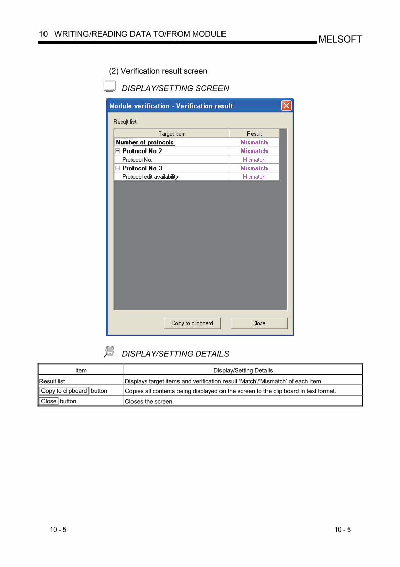
10 - 5 10 - 5
MELSOFT10 WRITING/READING DATA TO/FROM MODULE
(2) Verification result screen
DISPLAY/SETTING SCREEN
DISPLAY/SETTING DETAILS Item Display/Setting Details
Result list Displays target items and verification result ‘Match’/’Mismatch’ of each item. Copy to clipboard button Copies all contents being displayed on the screen to the clip board in text format.
Close button Closes the screen.
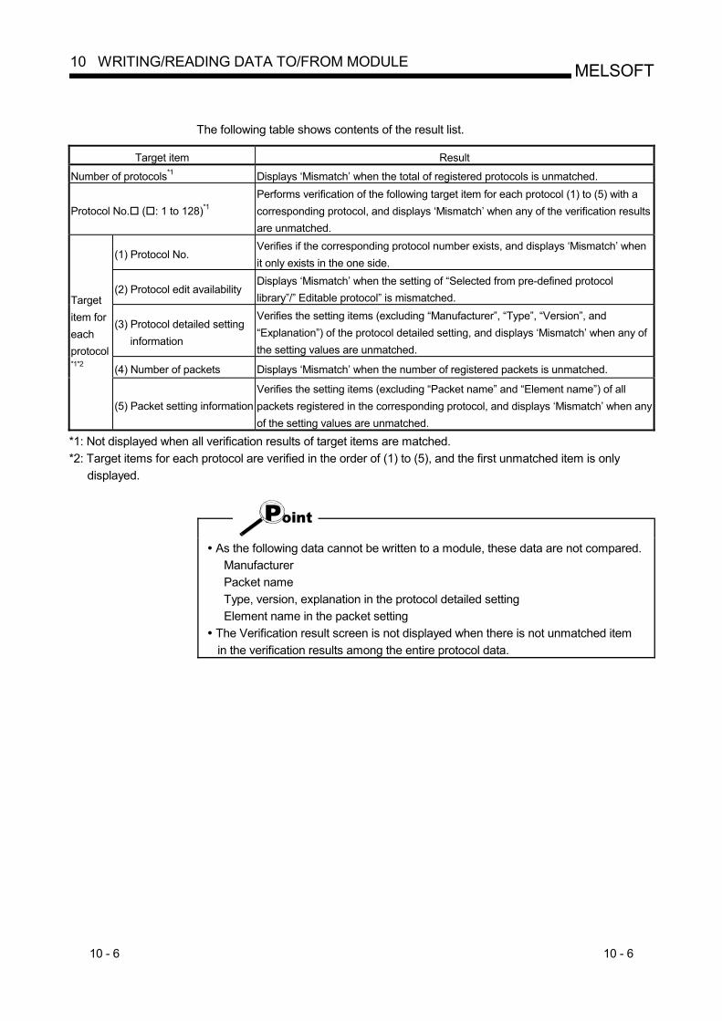
10 - 6 10 - 6
MELSOFT10 WRITING/READING DATA TO/FROM MODULE
The following table shows contents of the result list.
Target item Result
Number of protocols*1 Displays ‘Mismatch’ when the total of registered protocols is unmatched.
Protocol No. ( : 1 to 128)*1 Performs verification of the following target item for each protocol (1) to (5) with a corresponding protocol, and displays ‘Mismatch’ when any of the verification results are unmatched.
(1) Protocol No. Verifies if the corresponding protocol number exists, and displays ‘Mismatch’ when it only exists in the one side.
(2) Protocol edit availability Displays ‘Mismatch’ when the setting of “Selected from pre-defined protocol library”/” Editable protocol” is mismatched.
(3) Protocol detailed setting information
Verifies the setting items (excluding “Manufacturer”, “Type”, “Version”, and “Explanation”) of the protocol detailed setting, and displays ‘Mismatch’ when any of the setting values are unmatched.
(4) Number of packets Displays ‘Mismatch’ when the number of registered packets is unmatched.
Target item for each protocol*1*2
(5) Packet setting information Verifies the setting items (excluding “Packet name” and “Element name”) of all packets registered in the corresponding protocol, and displays ‘Mismatch’ when any of the setting values are unmatched.
*1: Not displayed when all verification results of target items are matched. *2: Target items for each protocol are verified in the order of (1) to (5), and the first unmatched item is only
displayed.
As the following data cannot be written to a module, these data are not compared.
Manufacturer Packet name Type, version, explanation in the protocol detailed setting Element name in the packet setting
The Verification result screen is not displayed when there is not unmatched item in the verification results among the entire protocol data.
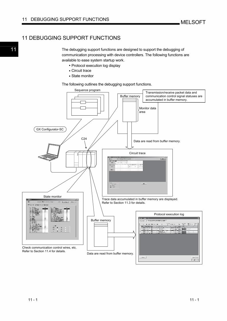
11 - 1 11 - 1
MELSOFT11 DEBUGGING SUPPORT FUNCTIONS
11 DEBUGGING SUPPORT FUNCTIONS
The debugging support functions are designed to support the debugging of communication processing with device controllers. The following functions are available to ease system startup work.
Protocol execution log display Circuit trace State monitor
The following outlines the debugging support functions.
Sequence program
Buffer memory
Monitor dataarea
Data are read from buffer memory.
Circuit trace
Trace data accumulated in buffer memory are displayed.Refer to Section 11.3 for details.
GX Configurator-SC
C24
State monitor
Check communication control wires, etc.Refer to Section 11.4 for details.
Transmission/receive packet data andcommunication control signal statuses areaccumulated in buffer memory.
Buffer memory
Protocol execution log
Data are read from buffer memory.
11
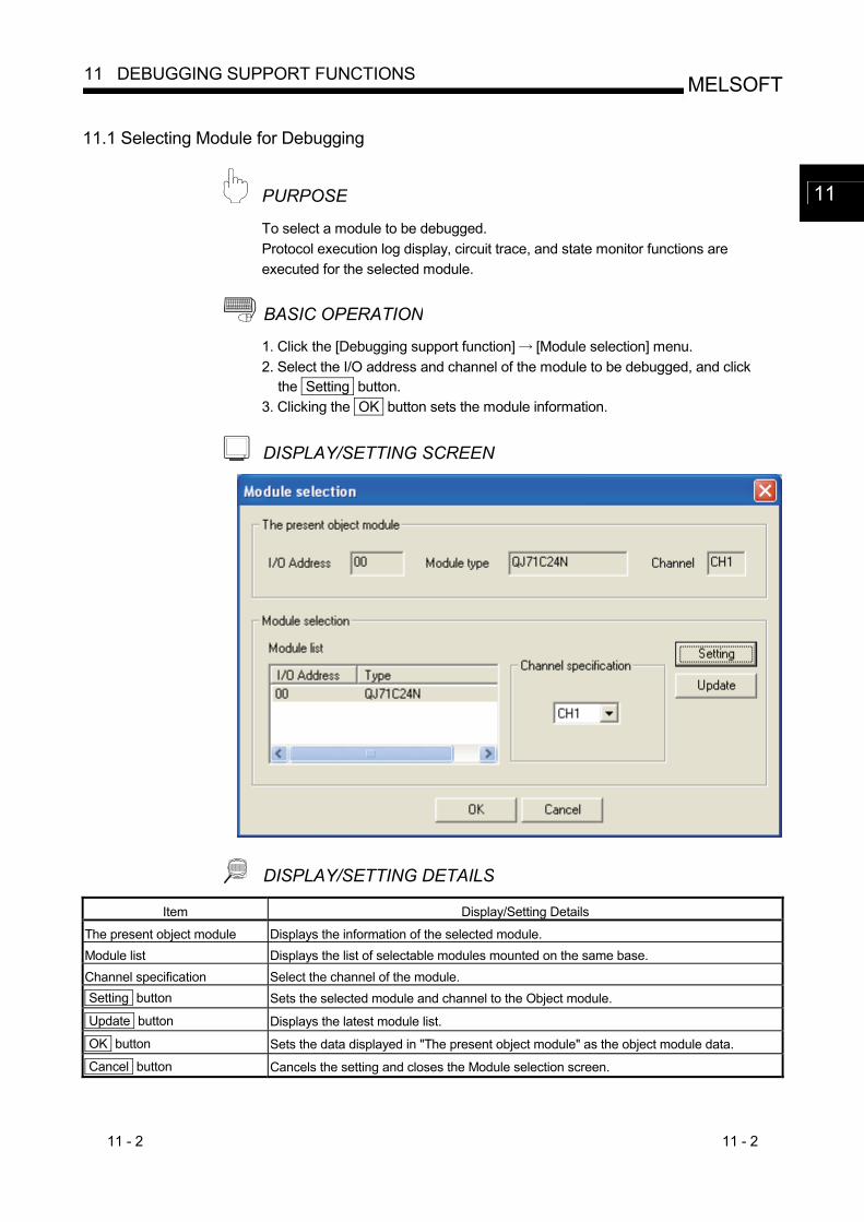
11 - 2 11 - 2
MELSOFT11 DEBUGGING SUPPORT FUNCTIONS
11.1 Selecting Module for Debugging
PURPOSE To select a module to be debugged. Protocol execution log display, circuit trace, and state monitor functions are executed for the selected module.
BASIC OPERATION 1. Click the [Debugging support function] [Module selection] menu. 2. Select the I/O address and channel of the module to be debugged, and click
the Setting button. 3. Clicking the OK button sets the module information.
DISPLAY/SETTING SCREEN
DISPLAY/SETTING DETAILS Item Display/Setting Details
The present object module Displays the information of the selected module. Module list Displays the list of selectable modules mounted on the same base. Channel specification Select the channel of the module. Setting button Sets the selected module and channel to the Object module.
Update button Displays the latest module list.
OK button Sets the data displayed in "The present object module" as the object module data.
Cancel button Cancels the setting and closes the Module selection screen.
11
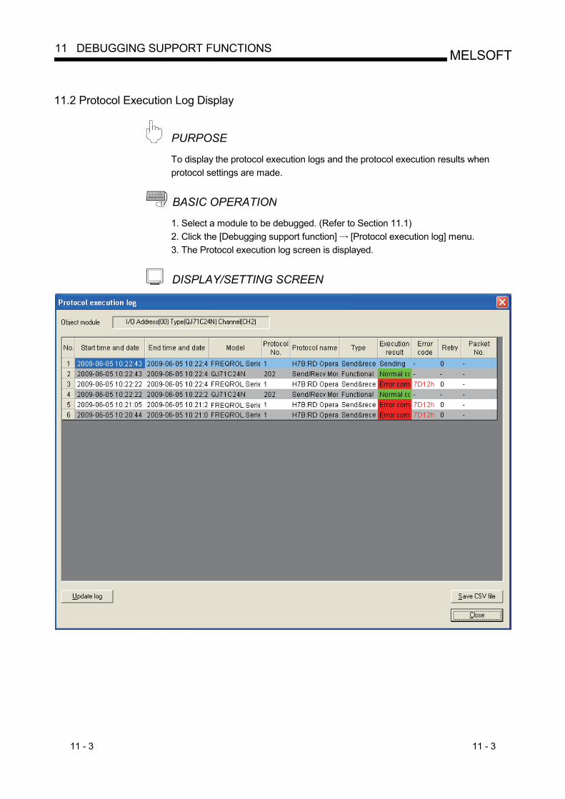
11 - 3 11 - 3
MELSOFT11 DEBUGGING SUPPORT FUNCTIONS
11.2 Protocol Execution Log Display
PURPOSE To display the protocol execution logs and the protocol execution results when protocol settings are made.
BASIC OPERATION 1. Select a module to be debugged. (Refer to Section 11.1) 2. Click the [Debugging support function] [Protocol execution log] menu. 3. The Protocol execution log screen is displayed.
DISPLAY/SETTING SCREEN
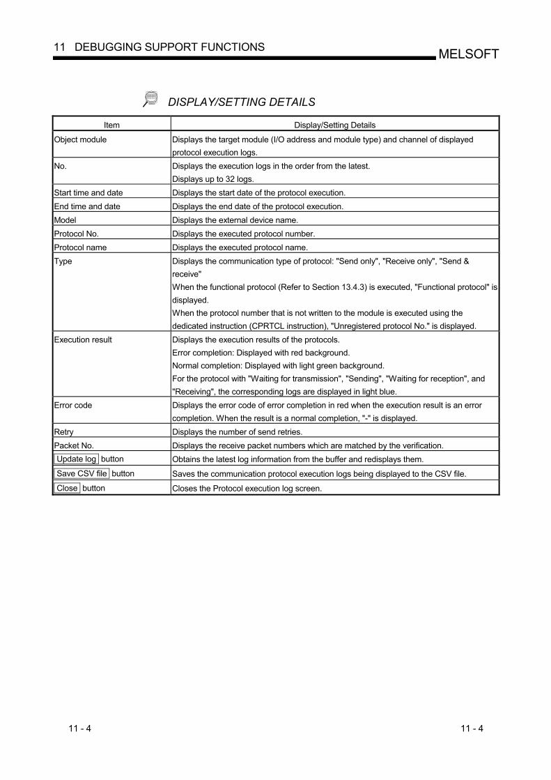
11 - 4 11 - 4
MELSOFT11 DEBUGGING SUPPORT FUNCTIONS
DISPLAY/SETTING DETAILS Item Display/Setting Details
Object module Displays the target module (I/O address and module type) and channel of displayed protocol execution logs.
No. Displays the execution logs in the order from the latest. Displays up to 32 logs.
Start time and date Displays the start date of the protocol execution. End time and date Displays the end date of the protocol execution. Model Displays the external device name. Protocol No. Displays the executed protocol number. Protocol name Displays the executed protocol name. Type Displays the communication type of protocol: "Send only", "Receive only", "Send &
receive" When the functional protocol (Refer to Section 13.4.3) is executed, "Functional protocol" is displayed. When the protocol number that is not written to the module is executed using the dedicated instruction (CPRTCL instruction), "Unregistered protocol No." is displayed.
Execution result Displays the execution results of the protocols. Error completion: Displayed with red background. Normal completion: Displayed with light green background. For the protocol with "Waiting for transmission", "Sending", "Waiting for reception", and "Receiving", the corresponding logs are displayed in light blue.
Error code Displays the error code of error completion in red when the execution result is an error completion. When the result is a normal completion, "-" is displayed.
Retry Displays the number of send retries. Packet No. Displays the receive packet numbers which are matched by the verification. Update log button Obtains the latest log information from the buffer and redisplays them.
Save CSV file button Saves the communication protocol execution logs being displayed to the CSV file.
Close button Closes the Protocol execution log screen.
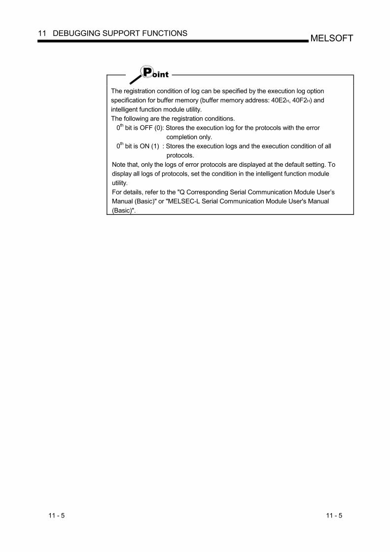
11 - 5 11 - 5
MELSOFT11 DEBUGGING SUPPORT FUNCTIONS
The registration condition of log can be specified by the execution log option specification for buffer memory (buffer memory address: 40E2H, 40F2H) and intelligent function module utility. The following are the registration conditions.
0th bit is OFF (0): Stores the execution log for the protocols with the error completion only.
0th bit is ON (1) : Stores the execution logs and the execution condition of all protocols.
Note that, only the logs of error protocols are displayed at the default setting. To display all logs of protocols, set the condition in the intelligent function module utility. For details, refer to the "Q Corresponding Serial Communication Module User’s Manual (Basic)" or "MELSEC-L Serial Communication Module User's Manual (Basic)".
11 - 6 11 - 6
MELSOFT11 DEBUGGING SUPPORT FUNCTIONS
11.3 Circuit Trace
PURPOSE To trace the communication data and communication control signals with device controller.
REMARK
The circuit trace function displays the data accumulated in the monitor buffer of a module.
11.3.1 Starting the circuit trace
PURPOSE To trace the communication data and communication control signal status, store the trace data in the monitor buffer.
BASIC OPERATION 1. Select a module to be debugged. (Refer to Section 11.1) 2. Select the [Debugging support function] [Circuit trace] [Circuit trace] menu. 3. Click the Start button to start trace. 4. When the monitor buffer becomes full or the Stop button is clicked, the trace
data are displayed. 5. Confirm the send/receive packets and communication control signals from the
displayed trace result.
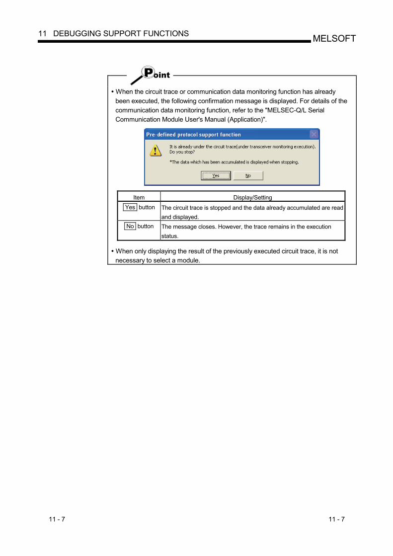
11 - 7 11 - 7
MELSOFT11 DEBUGGING SUPPORT FUNCTIONS
When the circuit trace or communication data monitoring function has already been executed, the following confirmation message is displayed. For details of the communication data monitoring function, refer to the "MELSEC-Q/L Serial Communication Module User's Manual (Application)".
Item Display/Setting
Yes button The circuit trace is stopped and the data already accumulated are read and displayed.
No button The message closes. However, the trace remains in the execution status.
When only displaying the result of the previously executed circuit trace, it is not necessary to select a module.
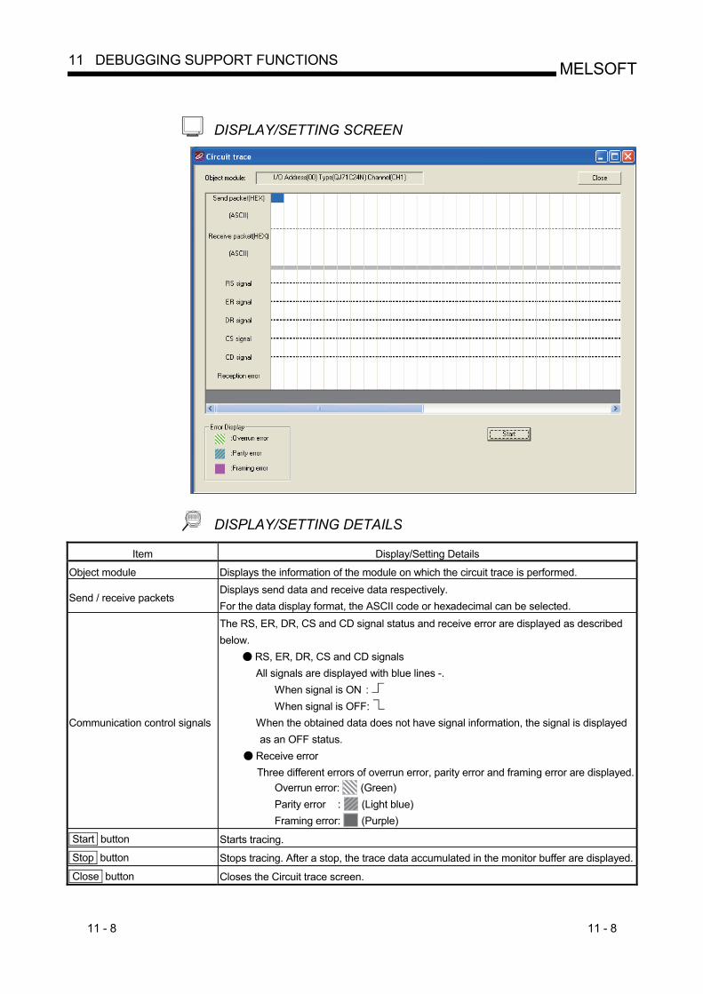
11 - 8 11 - 8
MELSOFT11 DEBUGGING SUPPORT FUNCTIONS
DISPLAY/SETTING SCREEN
DISPLAY/SETTING DETAILS Item Display/Setting Details
Object module Displays the information of the module on which the circuit trace is performed.
Send / receive packets Displays send data and receive data respectively. For the data display format, the ASCII code or hexadecimal can be selected.
Communication control signals
The RS, ER, DR, CS and CD signal status and receive error are displayed as described below.
RS, ER, DR, CS and CD signals All signals are displayed with blue lines -.
When signal is ON : When signal is OFF:
When the obtained data does not have signal information, the signal is displayed as an OFF status.
Receive error Three different errors of overrun error, parity error and framing error are displayed.
Overrun error: (Green) Parity error : (Light blue) Framing error: (Purple)
Start button Starts tracing.
Stop button Stops tracing. After a stop, the trace data accumulated in the monitor buffer are displayed.
Close button Closes the Circuit trace screen.
11 - 9 11 - 9
MELSOFT11 DEBUGGING SUPPORT FUNCTIONS
11.3.2 Circuit trace option
PURPOSE To set the monitor buffer area starting address and size of a module that stores the circuit trace data.
BASIC OPERATION 1. Select the [Debugging support function] [Circuit trace] [Circuit trace] menu
to display the Circuit trace screen. 2. Select the [Debugging support function] [Circuit trace] [Circuit trace option]
menu to display the Circuit trace option screen. 3. Set the "Monitor buffer starting address" and "Monitor buffer size", and click
the Write button.
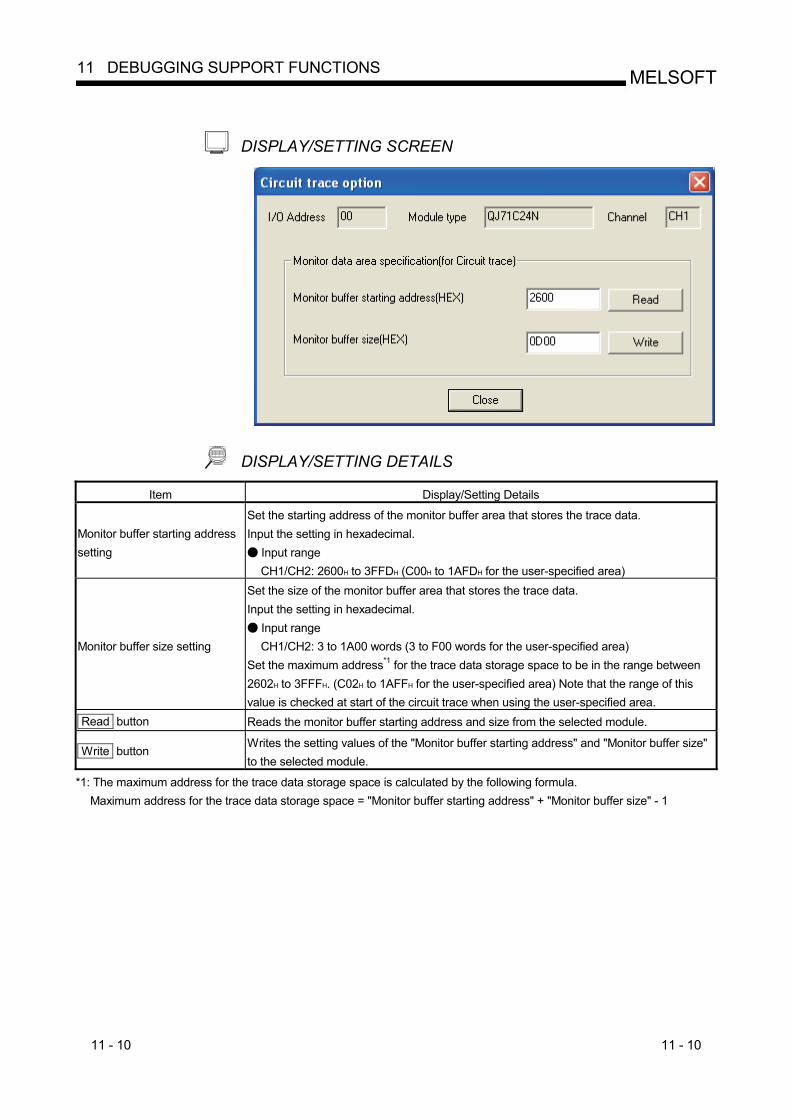
11 - 10 11 - 10
MELSOFT11 DEBUGGING SUPPORT FUNCTIONS
DISPLAY/SETTING SCREEN
DISPLAY/SETTING DETAILS Item Display/Setting Details
Monitor buffer starting address setting
Set the starting address of the monitor buffer area that stores the trace data. Input the setting in hexadecimal.
Input range CH1/CH2: 2600H to 3FFDH (C00H to 1AFDH for the user-specified area)
Monitor buffer size setting
Set the size of the monitor buffer area that stores the trace data. Input the setting in hexadecimal.
Input range CH1/CH2: 3 to 1A00 words (3 to F00 words for the user-specified area)
Set the maximum address*1 for the trace data storage space to be in the range between 2602H to 3FFFH. (C02H to 1AFFH for the user-specified area) Note that the range of this value is checked at start of the circuit trace when using the user-specified area.
Read button Reads the monitor buffer starting address and size from the selected module.
Write button Writes the setting values of the "Monitor buffer starting address" and "Monitor buffer size" to the selected module.
*1: The maximum address for the trace data storage space is calculated by the following formula. Maximum address for the trace data storage space = "Monitor buffer starting address" + "Monitor buffer size" - 1
11 - 11 11 - 11
MELSOFT11 DEBUGGING SUPPORT FUNCTIONS
11.3.3 Opening the circuit trace file
PURPOSE To read and display the trace data saved in the personal computer.
BASIC OPERATION Select the [Debugging support function] [Circuit trace] [Open circuit trace file] menu.
11.3.4 Saving the circuit trace file
PURPOSE To save the trace data obtained by the circuit trace to the personal computer.
BASIC OPERATION Select the [Debugging support function] [Circuit trace] [Save circuit trace file] menu.
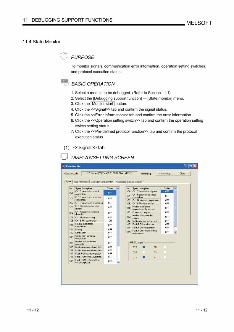
11 - 12 11 - 12
MELSOFT11 DEBUGGING SUPPORT FUNCTIONS
11.4 State Monitor
PURPOSE To monitor signals, communication error information, operation setting switches, and protocol execution status.
BASIC OPERATION 1. Select a module to be debugged. (Refer to Section 11.1) 2. Select the [Debugging support function] [State monitor] menu. 3. Click the Monitor start button. 4. Click the <<Signal>> tab and confirm the signal status. 5. Click the <<Error information>> tab and confirm the error information. 6. Click the <<Operation setting switch>> tab and confirm the operation setting
switch setting status. 7. Click the <<Pre-defined protocol function>> tab and confirm the protocol
execution status
(1) <<Signal>> tab
DISPLAY/SETTING SCREEN
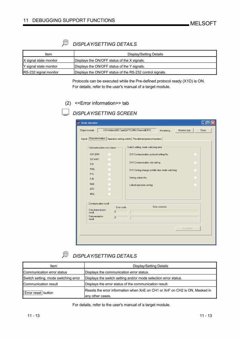
11 - 13 11 - 13
MELSOFT11 DEBUGGING SUPPORT FUNCTIONS
DISPLAY/SETTING DETAILS Item Display/Setting Details
X signal state monitor Displays the ON/OFF status of the X signals. Y signal state monitor Displays the ON/OFF status of the Y signals. RS-232 signal monitor Displays the ON/OFF status of the RS-232 control signals.
Protocols can be executed while the Pre-defined protocol ready (X1D) is ON. For details, refer to the user's manual of a target module.
(2) <<Error information>> tab
DISPLAY/SETTING SCREEN
DISPLAY/SETTING DETAILS Item Display/Setting Details
Communication error status Displays the communication error status. Switch setting, mode switching error Displays the switch setting and/or mode selection error status. Communication result Displays the error status of the communication result.
Error reset button Resets the error information when XnE on CH1 or XnF on CH2 is ON. Masked in any other cases.
For details, refer to the user's manual of a target module.
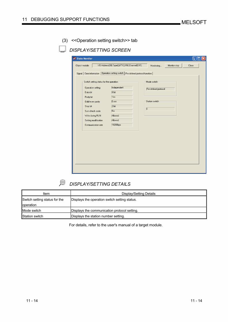
11 - 14 11 - 14
MELSOFT11 DEBUGGING SUPPORT FUNCTIONS
(3) <<Operation setting switch>> tab
DISPLAY/SETTING SCREEN
DISPLAY/SETTING DETAILS Item Display/Setting Details
Switch setting status for the operation
Displays the operation switch setting status.
Mode switch Displays the communication protocol setting. Station switch Displays the station number setting.
For details, refer to the user's manual of a target module.
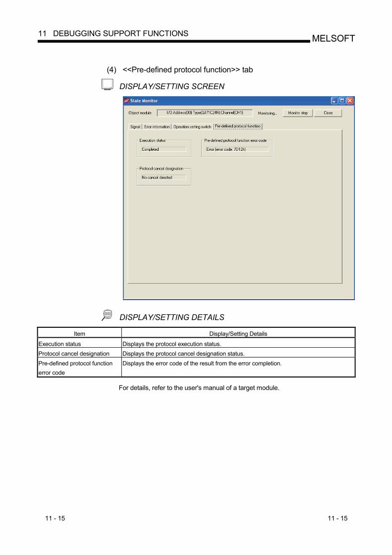
11 - 15 11 - 15
MELSOFT11 DEBUGGING SUPPORT FUNCTIONS
(4) <<Pre-defined protocol function>> tab
DISPLAY/SETTING SCREEN
DISPLAY/SETTING DETAILS Item Display/Setting Details
Execution status Displays the protocol execution status. Protocol cancel designation Displays the protocol cancel designation status. Pre-defined protocol function error code
Displays the error code of the result from the error completion.
For details, refer to the user's manual of a target module.
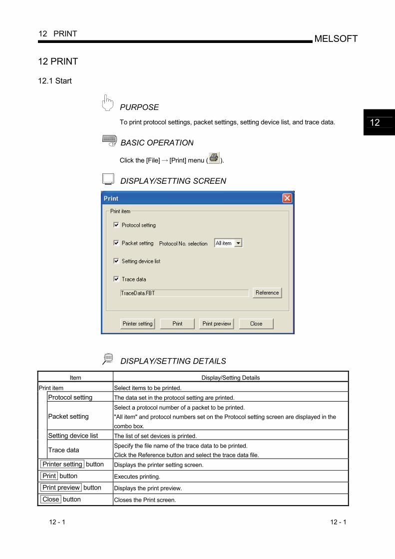
12 - 1 12 - 1
MELSOFT12 PRINT
12 PRINT
12.1 Start
PURPOSE To print protocol settings, packet settings, setting device list, and trace data.
BASIC OPERATION
Click the [File] [Print] menu ( ).
DISPLAY/SETTING SCREEN
DISPLAY/SETTING DETAILS Item Display/Setting Details
Print item Select items to be printed. Protocol setting The data set in the protocol setting are printed.
Packet setting Select a protocol number of a packet to be printed. "All item" and protocol numbers set on the Protocol setting screen are displayed in the combo box.
Setting device list The list of set devices is printed.
Trace data Specify the file name of the trace data to be printed. Click the Reference button and select the trace data file.
Printer setting button Displays the printer setting screen.
Print button Executes printing.
Print preview button Displays the print preview.
Close button Closes the Print screen.
12
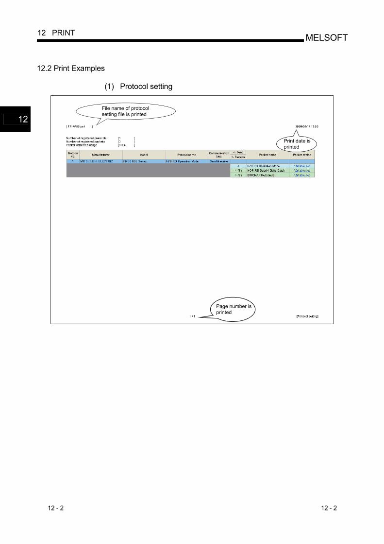
12 - 2 12 - 2
MELSOFT12 PRINT
12.2 Print Examples
(1) Protocol setting
File name of protocolsetting file is printed
Page number isprinted
Print date isprinted
12
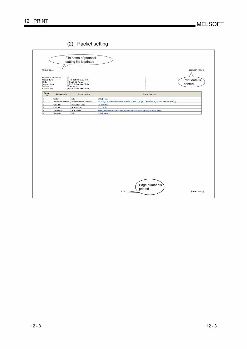
12 - 3 12 - 3
MELSOFT12 PRINT
(2) Packet setting
File name of protocolsetting file is printed
Page number isprinted
Print date isprinted
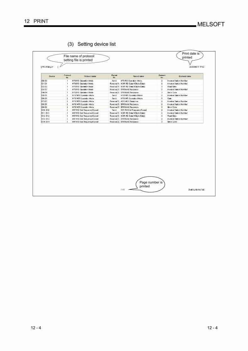
12 - 4 12 - 4
MELSOFT12 PRINT
(3) Setting device list
File name of protocolsetting file is printed
Page number isprinted
Print date isprinted
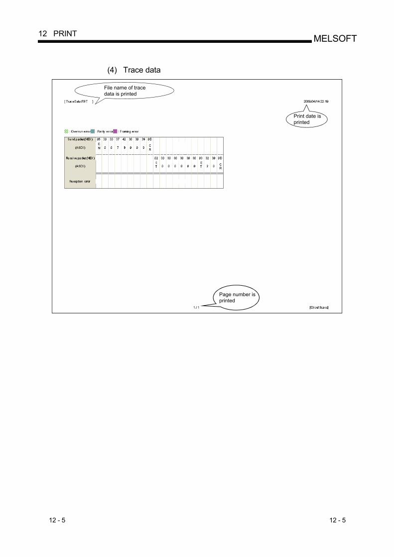
12 - 5 12 - 5
MELSOFT12 PRINT
(4) Trace data
File name of tracedata is printed
Page number isprinted
Print date isprinted
13 - 1 13 - 1
MELSOFT13 SETTINGS FOR Q SERIES C24N / L SERIES C24 MODULE
13 SETTINGS FOR Q SERIES C24N / L SERIES C24 MODULE
This chapter explains the specification overview of Q series C24N / L series C24 modules required when using the pre-defined protocol function. For the terms described in this chapter, refer to the "Q Corresponding Serial Communication Module User's Manual (Basic)" or "MELSEC-L Serial Communication Module User's Manual (Basic)".
13.1 I/O Signals of Programmable Controller CPU
This section explains the I/O signals of Q series C24N / L series C24 modules used for the pre-defined protocol. For the I/O signals not used in the pre-defined protocol communication, refer to the "Q Corresponding Serial Communication Module User's Manual (Basic)" or "MELSEC-L Serial Communication Module User's Manual (Basic)".
13
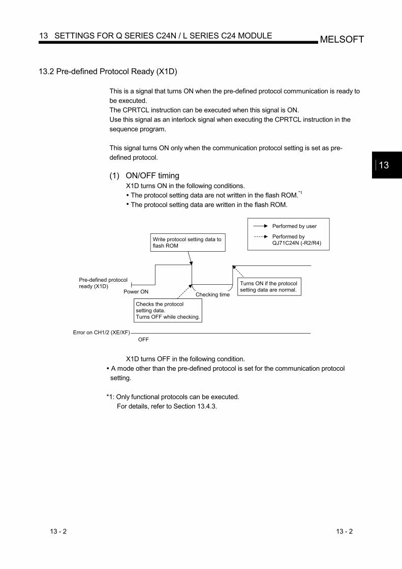
13 - 2 13 - 2
MELSOFT13 SETTINGS FOR Q SERIES C24N / L SERIES C24 MODULE
13.2 Pre-defined Protocol Ready (X1D)
This is a signal that turns ON when the pre-defined protocol communication is ready to be executed. The CPRTCL instruction can be executed when this signal is ON. Use this signal as an interlock signal when executing the CPRTCL instruction in the sequence program. This signal turns ON only when the communication protocol setting is set as pre-defined protocol. (1) ON/OFF timing
X1D turns ON in the following conditions. The protocol setting data are not written in the flash ROM.*1 The protocol setting data are written in the flash ROM.
Error on CH1/2 (XE/XF)OFF
Checks the protocolsetting data.Turns OFF while checking.
Turns ON if the protocolsetting data are normal.
Pre-defined protocolready (X1D)
Power ON
Write protocol setting data toflash ROM
Performed by user
Performed byQJ71C24N (-R2/R4)
Checking time
X1D turns OFF in the following condition. A mode other than the pre-defined protocol is set for the communication protocol setting.
*1: Only functional protocols can be executed.
For details, refer to Section 13.4.3.
13
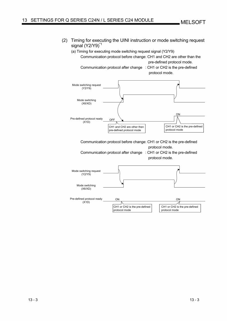
13 - 3 13 - 3
MELSOFT13 SETTINGS FOR Q SERIES C24N / L SERIES C24 MODULE
(2) Timing for executing the UINI instruction or mode switching request
signal (Y2/Y9)*1 (a) Timing for executing mode switching request signal (Y2/Y9)
Communication protocol before change: CH1 and CH2 are other than the pre-defined protocol mode.
Communication protocol after change : CH1 or CH2 is the pre-defined protocol mode.
Mode switching request(Y2/Y9)
Mode switching(X6/XD)
Pre-defined protocol ready(X1D)
CH1 and CH2 are other thenpre-defined protocol mode
CH1 or CH2 is the pre-definedprotocol mode
ON
OFF
Communication protocol before change: CH1 or CH2 is the pre-defined
protocol mode. Communication protocol after change : CH1 or CH2 is the pre-defined
protocol mode.
ON ON
Mode switching request(Y2/Y9)
Mode switching(X6/XD)
Pre-defined protocol ready(X1D)
CH1 or CH2 is the pre-definedprotocol mode
CH1 or CH2 is the pre-definedprotocol mode
13 - 4 13 - 4
MELSOFT13 SETTINGS FOR Q SERIES C24N / L SERIES C24 MODULE
Communication protocol before change: CH1 or CH2 is the pre-defined
protocol mode. Communication protocol after change : CH1 and CH2 are other than the
pre-defined protocol mode.
Mode switching request(Y2/Y9)
Mode switching(X6/XD)
Pre-defined protocol ready(X1D)
CH1 or CH2 is the pre-definedprotocol mode
OFF
ON
CH1 and CH2 are other then pre-definedprotocol mode
*1: Based on either following condition; the protocol setting data written to the flash
ROM are normal, or the protocol setting data are not written to the flash ROM.
13 - 5 13 - 5
MELSOFT13 SETTINGS FOR Q SERIES C24N / L SERIES C24 MODULE
(b) Timing for executing the UINI instruction
Communication protocol before change: CH1 and CH2 are other than the pre-defined protocol mode.
Communication protocol after change : CH1 or CH2 is the pre-defined protocol mode.
Sequence program
UINI instruction
Completion deviceOFF
Status indicationdevice at completion
ON
ON
Errorcompletion
NormalcompletionOne scan
UINI instruction execution
ENDprocessing
ENDprocessing
ENDprocessing
ENDprocessing
Setting processing
Mode switchingsignal (X6/XD)
ON
Communication disabledQ series C24N / L series C24
Pre-defined protocolready (X1D)
CH1 and CH2 are other thenpre-defined protocol mode
CH1 or CH2 is thepre-defined protocol mode
ON
OFF
OFF
OFF
Communication protocol before change: CH1 or CH2 is the pre-defined
protocol mode. Communication protocol after change : CH1 or CH2 is the pre-defined
protocol mode.
Sequence program
UINI instruction
Completion device OFF
Status indicationdevice at completion
Errorcompletion
NormalcompletionOne scan
UINI instruction execution
ENDprocessing
ENDprocessing
ENDprocessing
ENDprocessing
Setting processing
Mode switchingsignal (X6/XD)
Communication disabled
Q series C24N / L series C24
Pre-defined protocolready (X1D)
CH1 or CH2 is thepre-defined protocol mode
OFF
OFFON
ON ON
CH1 or CH2 is thepre-defined protocol mode
ON
ON
13 - 6 13 - 6
MELSOFT13 SETTINGS FOR Q SERIES C24N / L SERIES C24 MODULE
Communication protocol before change: CH1 or CH2 is the pre-defined
protocol mode. Communication protocol after change : CH1 and CH2 are other than the
pre-defined protocol mode.
Sequence program
UINI instruction
Completion device OFF
Status indicationdevice at completion
Errorcompletion
NormalcompletionOne scan
UINI instruction execution
ENDprocessing
ENDprocessing
ENDprocessing
ENDprocessing
Setting processing
Mode switchingsignal (X6/XD)
Communication disabled
Q series C24N / L series C24
Pre-defined protocolready (X1D)
OFF
OFFON
ON
ON
ON
OFFCH1 or CH2 is thepre-defined protocol mode
CH1 and CH2 are other then pre-defined protocol mode
13 - 7 13 - 7
MELSOFT13 SETTINGS FOR Q SERIES C24N / L SERIES C24 MODULE
13.3 List of Applications and Assignments of Buffer Memory
This section explains the buffer memory (masked areas in the table) used for the pre-defined protocol function. For the buffer memory that does not relate to the pre-defined protocol function, refer to the "Q Corresponding Serial Communication Module User's Manual (Basic)" or "MELSEC-L Serial Communication Module User's Manual (Basic)". (1) Configuration of the buffer memory
A buffer memory consists of a user area and a system area as shown below. (a) User area
1) This is the area where users write/read data. 2) The user area consists of areas for storing setting values for data
communication, for actual data communication, and for storing communication status and communication error information.
3) Data read/write to the user area should be performed following the instructions in the corresponding detailed reference page.
(b) System area This area is used by the Q series C24N / L series C24 module system.
(2) List of buffer memory assignments
A buffer memory is configured with 16 bits per address. Name, initial value, etc. of each address of the buffer memory is shown in the lists on the following pages.
1) Abbreviations in the Applicable protocol column MC : MC protocol Non : Non procedure protocol Bi : Bidirectional protocol Pre : Pre-defined protocol
2) Meaning of symbols shown in the Applicable protocol column The following symbols are assigned to protocols related to the setting values of a corresponding area and to areas used for controlled with user settings, and indicate what kind of access is allowed to the area in question. RW : Area where it is possible to read/write data from/to the
programmable controller CPU and the other device. R : Area where only reading is possible from the programmable
controller CPU and the other device. – : System area used by the system or area not used by the
corresponding protocol. 3) Meaning of symbols shown in the Registration allowed/not allowed
column Indicates whether or not it is possible to use a value in the corresponding area by registering it to the flash ROM of the Q series C24N / L series C24 module. Allowed : Area that can be registered and used. Not allowed : Area that cannot be registered.
13 - 8 13 - 8
MELSOFT13 SETTINGS FOR Q SERIES C24N / L SERIES C24 MODULE
IMPORTANT Do not write data in the "System area" of the buffer memory. If data are written to any of the system areas, the programmable controller system may malfunction. Some of the user areas are partially system areas. Care must be taken when reading/writing data from/to the buffer memory.
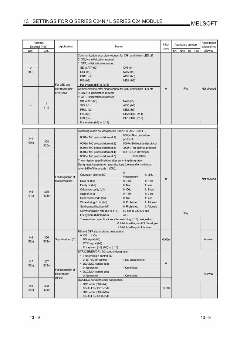
13 - 9 13 - 9
MELSOFT13 SETTINGS FOR Q SERIES C24N / L SERIES C24 MODULE
Address
Decimal (Hex) Applicable protocol
CH1 CH2 Application Name
Initial value
MC Non Bi Pre
Registration allowed/not
allowed Communication error clear request for CH1 and to turn LED off 0: ON, No initialization request 1: OFF, Initialization requested
SD WAIT (b0) C/N (b4) SIO (b1)) NAK (b5) PRO. (b2) ACK. (b6) P/S (b3) NEU. (b7)
0 (0H)
—
For system (b8) to (b15) Communication error clear request for CH2 and to turn LED off 0: ON, No initialization request 1: OFF, Initialization requested
SD WAIT (b0) NAK (b5) SIO (b1) ACK. (b6) PRO. (b2) NEU. (b7) P/S (b3) CH2 ERR. (b14) C/N (b4) CH1 ERR. (b15)
— 1
(1H)
For LED and communication error clear
For system (b8) to (b13)
0 RW Not allowed
Switching mode no. designation (0001H to 0007H, 00FFH)
0001H: MC protocol (format 1) 0006H: Non procedure protocol
0002H: MC protocol (format 2) 0007H: Bidirectional protocol 0003H: MC protocol (format 3) 0009H: Pre-defined protocol 0004H: MC protocol (format 4)
144 (90H)
304
(130H)
0005H: MC protocol (format 5) 00FFH: GX Developer
connection Transmission specifications after switching designation Designates transmission specifications (below) after switching when b15 of this area is 1 (ON).
Operation setting (b0) 0: Independent
1: Link
Data bit (b1) 0: 7 bit 1: 8 bit Parity bit (b2) 0: No 1: Yes Odd/even parity (b3) 0: Odd 1: Even Stop bit (b4) 0: 1 bit 1: 2 bit Sum check code (b5) 0: No 1: Yes Write during RUN (b6) 0: Prohibited 1: Allowed Setting modification (b7) 0: Prohibited 1: Allowed Communication rate (b8 to b11) 50 bps to 230400 bps For system (b12 to b14) All 0
145 (91H)
305 (131H)
For designation of mode switching
Transmission specifications after switching (b15) designation 0: Match settings in GX Developer 1: Match settings in this area
0 Not allowed
146 (92H)
306 (132H)
Signal setting (*1)
RS and DTR signal status designation 0: Off 1: On
RS signal (b0) DTR signal (b2) For system (b1), (b3) to (b15)
0005H Allowed
DTR/DSR(ER/DR), DC control designation
147 (93H)
307 (133H)
Transmission control (b0) 0: DTR/DSR control 1: DC code control
DC1/DC3 control (b8) 0: No control 1: Controlled
DC2/DC4 control (b9) 0: No control 1: Controlled
0
DC1/DC3(Xon/Xoff) code designation
148 (94H)
308 (134H)
For designation of transmission control
DC1 code (b0 to b7) 00H to FFH: DC1 code
DC3 code (b8 to b15) 00H to FFH: DC3 code
1311H
RW
Allowed
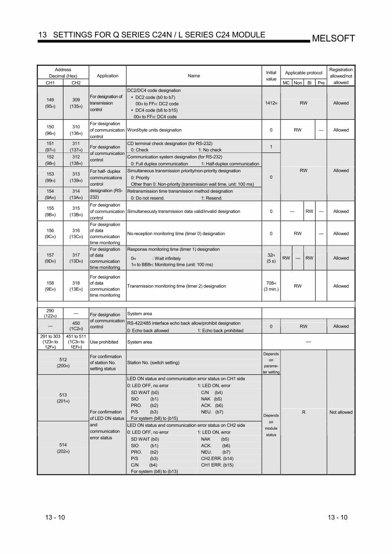
13 - 10 13 - 10
MELSOFT13 SETTINGS FOR Q SERIES C24N / L SERIES C24 MODULE
Address
Decimal (Hex) Applicable protocol
CH1 CH2 Application Name
Initial value
MC Non Bi Pre
Registration allowed/not
allowed DC2/DC4 code designation
149 (95H)
309 (135H)
For designation of transmission control
DC2 code (b0 to b7) 00H to FFH: DC2 code
DC4 code (b8 to b15) 00H to FFH: DC4 code
1412H RW Allowed
150 (96H)
310 (136H)
For designation of communication control
Word/byte units designation 0 RW — Allowed
151 (97H)
311 (137H)
CD terminal check designation (for RS-232) 0: Check 1: No check
1
Communication system designation (for RS-232) 152 (98H)
312 (138H)
For designation of communication control
0: Full duplex communication 1: Half-duplex communication Simultaneous transmission priority/non-priority designation
153 (99H)
313 (139H) 0: Priority
Other than 0: Non-priority (transmission wait time, unit: 100 ms) Retransmission time transmission method designation 154
(9AH) 314
(13AH)
For half- duplex communications control designation (RS-232) 0: Do not resend. 1: Resend.
0 RW Allowed
155 (9BH)
315 (13BH)
For designation of communication control
Simultaneously transmission data valid/invalid designation 0 — RW — Allowed
156 (9CH)
316 (13CH)
For designation of data communication time monitoring
No-reception monitoring time (timer 0) designation 0 RW — Allowed
Response monitoring time (timer 1) designation 157
(9DH) 317
(13DH)
For designation of data communication time monitoring
0H : Wait infinitely 1H to BB8H: Monitoring time (unit: 100 ms)
32H (5 s) RW — RW Allowed
158 (9EH)
318 (13EH)
For designation of data communication time monitoring
Transmission monitoring time (timer 2) designation 708H (3 min.)
RW Allowed
290
(122H) — System area
RS-422/485 interface echo back allow/prohibit designation — 450
(1C2H)
For designation of communication control
0: Echo back allowed 1: Echo back prohibited 0 RW Allowed
291 to 303 (123H to 12FH)
451 to 511 (1C3H to 1EFH)
Use prohibited System area —
512 (200H)
For confirmation of station No. setting status
Station No. (switch setting)
Depends on
parame-ter setting
LED ON status and communication error status on CH1 side 0: LED OFF, no error 1: LED ON, error
513 (201H)
SD WAIT (b0) SIO (b1) PRO. (b2) P/S (b3) For system (b8) to (b15)
C/N (b4) NAK (b5) ACK. (b6) NEU. (b7)
LED ON status and communication error status on CH2 side 0: LED OFF, no error 1: LED ON, error
514 (202H)
For confirmation of LED ON status and communication error status SD WAIT (b0)
SIO (b1) PRO. (b2) P/S (b3) C/N (b4) For system (b8) to (b13)
NAK (b5) ACK. (b6) NEU. (b7) CH2.ERR. (b14) CH1 ERR. (b15)
Depends on
module status
R Not allowed
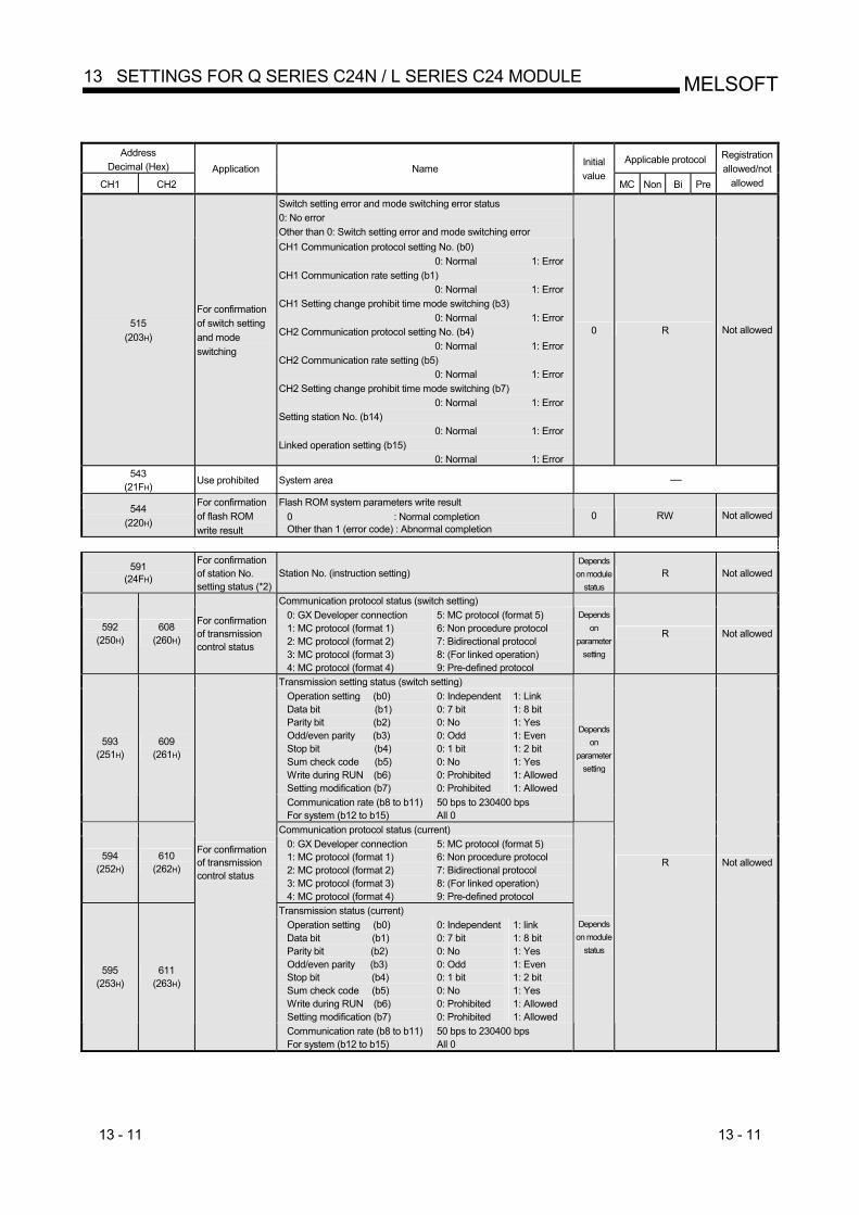
13 - 11 13 - 11
MELSOFT13 SETTINGS FOR Q SERIES C24N / L SERIES C24 MODULE
Address
Decimal (Hex) Applicable protocol
CH1 CH2 Application Name
Initial value
MC Non Bi Pre
Registration allowed/not
allowed
Switch setting error and mode switching error status 0: No error Other than 0: Switch setting error and mode switching error
515 (203H)
For confirmation of switch setting and mode switching
CH1 Communication protocol setting No. (b0) 0: Normal 1: Error
CH1 Communication rate setting (b1) 0: Normal 1: Error
CH1 Setting change prohibit time mode switching (b3) 0: Normal 1: Error
CH2 Communication protocol setting No. (b4) 0: Normal 1: Error
CH2 Communication rate setting (b5) 0: Normal 1: Error
CH2 Setting change prohibit time mode switching (b7) 0: Normal 1: Error
Setting station No. (b14) 0: Normal 1: Error
Linked operation setting (b15) 0: Normal 1: Error
0 R Not allowed
543 (21FH)
Use prohibited System area —
Flash ROM system parameters write result 544 (220H)
For confirmation of flash ROM write result
0 : Normal completion Other than 1 (error code) : Abnormal completion
0 RW Not allowed
591 (24FH)
For confirmation of station No. setting status (*2)
Station No. (instruction setting) Depends
on module status
R Not allowed
Communication protocol status (switch setting)
592 (250H)
608 (260H)
For confirmation of transmission control status
0: GX Developer connection 1: MC protocol (format 1) 2: MC protocol (format 2) 3: MC protocol (format 3) 4: MC protocol (format 4)
5: MC protocol (format 5) 6: Non procedure protocol 7: Bidirectional protocol 8: (For linked operation) 9: Pre-defined protocol
Depends on
parameter setting
R Not allowed
Transmission setting status (switch setting) Operation setting (b0) Data bit (b1) Parity bit (b2) Odd/even parity (b3) Stop bit (b4) Sum check code (b5) Write during RUN (b6) Setting modification (b7)
0: Independent 0: 7 bit 0: No 0: Odd 0: 1 bit 0: No 0: Prohibited 0: Prohibited
1: Link 1: 8 bit 1: Yes 1: Even 1: 2 bit 1: Yes 1: Allowed 1: Allowed
593 (251H)
609 (261H)
Communication rate (b8 to b11) For system (b12 to b15)
50 bps to 230400 bps All 0
Depends on
parameter setting
Communication protocol status (current)
594 (252H)
610 (262H)
0: GX Developer connection 1: MC protocol (format 1) 2: MC protocol (format 2) 3: MC protocol (format 3) 4: MC protocol (format 4)
5: MC protocol (format 5) 6: Non procedure protocol 7: Bidirectional protocol 8: (For linked operation) 9: Pre-defined protocol
Transmission status (current) Operation setting (b0) Data bit (b1) Parity bit (b2) Odd/even parity (b3) Stop bit (b4) Sum check code (b5) Write during RUN (b6) Setting modification (b7)
0: Independent 0: 7 bit 0: No 0: Odd 0: 1 bit 0: No 0: Prohibited 0: Prohibited
1: link 1: 8 bit 1: Yes 1: Even 1: 2 bit 1: Yes 1: Allowed 1: Allowed
595 (253H)
611 (263H)
For confirmation of transmission control status
Communication rate (b8 to b11) For system (b12 to b15)
50 bps to 230400 bps All 0
Depends on module
status
R Not allowed
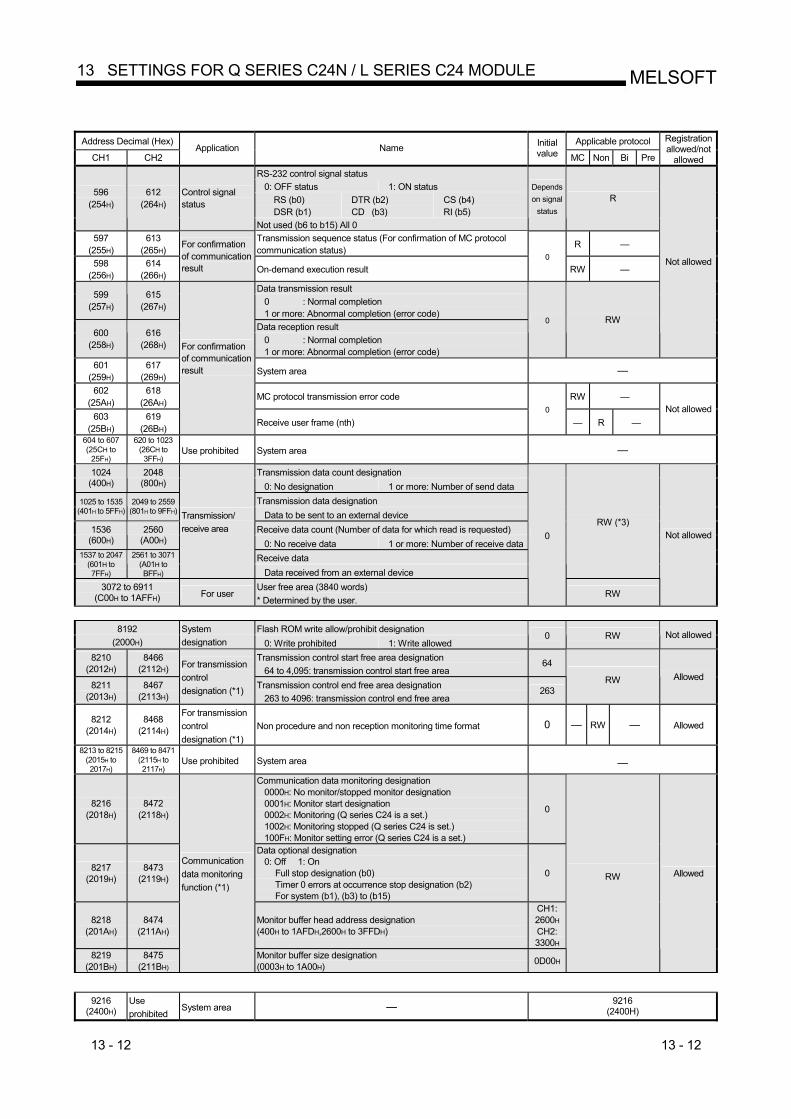
13 - 12 13 - 12
MELSOFT13 SETTINGS FOR Q SERIES C24N / L SERIES C24 MODULE
Address Decimal (Hex) Applicable protocol
CH1 CH2 Application Name Initial
value MC Non Bi Pre
Registration allowed/not
allowed RS-232 control signal status
0: OFF status 1: ON status RS (b0) DSR (b1)
DTR (b2) CD (b3)
CS (b4) RI (b5)
596 (254H)
612 (264H)
Control signal status
Not used (b6 to b15) All 0
Depends on signal
status R
597 (255H)
613 (265H)
Transmission sequence status (For confirmation of MC protocol communication status) R —
598 (256H)
614 (266H)
For confirmation of communication result On-demand execution result
0 RW —
Data transmission result 599 (257H)
615 (267H) 0 : Normal completion
1 or more: Abnormal completion (error code) Data reception result 600
(258H) 616
(268H) 0 : Normal completion 1 or more: Abnormal completion (error code)
0 RW
Not allowed
601 (259H)
617 (269H) System area —
602 (25AH)
618 (26AH) MC protocol transmission error code RW —
603 (25BH)
619 (26BH)
For confirmation of communication result
Receive user frame (nth) 0
— R — Not allowed
604 to 607 (25CH to
25FH)
620 to 1023 (26CH to
3FFH) Use prohibited System area —
Transmission data count designation 1024 (400H)
2048 (800H) 0: No designation 1 or more: Number of send data
Transmission data designation 1025 to 1535 (401H to 5FFH)
2049 to 2559 (801H to 9FFH) Data to be sent to an external device
Receive data count (Number of data for which read is requested) 1536 (600H)
2560 (A00H) 0: No receive data 1 or more: Number of receive data
Receive data 1537 to 2047 (601H to 7FFH)
2561 to 3071 (A01H to BFFH)
Transmission/ receive area
Data received from an external device
RW (*3)
3072 to 6911 (C00H to 1AFFH) For user
User free area (3840 words) * Determined by the user.
0
RW
Not allowed
Flash ROM write allow/prohibit designation 8192
(2000H) System designation 0: Write prohibited 1: Write allowed
0 RW Not allowed
8210 (2012H)
8466 (2112H)
Transmission control start free area designation 64 to 4,095: transmission control start free area
64
8211 (2013H)
8467 (2113H)
For transmission control designation (*1) Transmission control end free area designation
263 to 4096: transmission control end free area 263
RW Allowed
8212 (2014H)
8468 (2114H)
For transmission control designation (*1)
Non procedure and non reception monitoring time format 0 — RW — Allowed
8213 to 8215 (2015H to 2017H)
8469 to 8471 (2115H to 2117H)
Use prohibited System area —
8216 (2018H)
8472 (2118H)
Communication data monitoring designation 0000H: No monitor/stopped monitor designation 0001H: Monitor start designation 0002H: Monitoring (Q series C24 is a set.) 1002H: Monitoring stopped (Q series C24 is set.) 100FH: Monitor setting error (Q series C24 is a set.)
0
8217 (2019H)
8473 (2119H)
Data optional designation 0: Off 1: On
Full stop designation (b0) Timer 0 errors at occurrence stop designation (b2) For system (b1), (b3) to (b15)
0
8218 (201AH)
8474 (211AH)
Monitor buffer head address designation (400H to 1AFDH,2600H to 3FFDH)
CH1: 2600H
CH2: 3300H
8219 (201BH)
8475 (211BH)
Communication data monitoring function (*1)
Monitor buffer size designation (0003H to 1A00H) 0D00H
RW Allowed
9216
(2400H) Use prohibited
System area — 9216 (2400H)
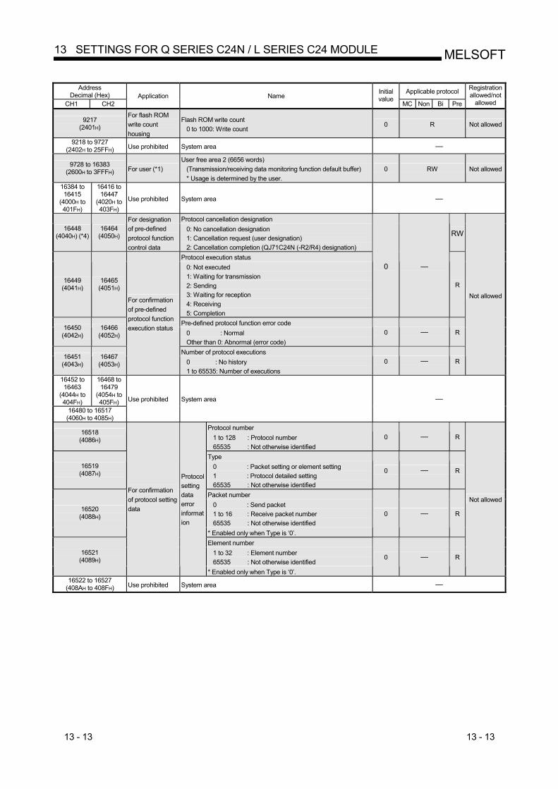
13 - 13 13 - 13
MELSOFT13 SETTINGS FOR Q SERIES C24N / L SERIES C24 MODULE
Address
Decimal (Hex) Applicable protocol
CH1 CH2 Application Name
Initial value
MC Non Bi Pre
Registration allowed/not
allowed
9217 (2401H)
For flash ROM write count housing
Flash ROM write count 0 to 1000: Write count
0 R Not allowed
9218 to 9727 (2402H to 25FFH) Use prohibited System area —
9728 to 16383 (2600H to 3FFFH) For user (*1)
User free area 2 (6656 words) (Transmission/receiving data monitoring function default buffer) * Usage is determined by the user.
0 RW Not allowed
16384 to 16415
(4000H to 401FH)
16416 to 16447
(4020H to 403FH)
Use prohibited System area —
Protocol cancellation designation 16448
(4040H) (*4) 16464
(4050H)
For designation of pre-defined protocol function control data
0: No cancellation designation 1: Cancellation request (user designation) 2: Cancellation completion (QJ71C24N (-R2/R4) designation)
RW
Protocol execution status
16449 (4041H)
16465 (4051H)
0: Not executed 1: Waiting for transmission 2: Sending 3: Waiting for reception 4: Receiving 5: Completion
0 —
R
Pre-defined protocol function error code 16450
(4042H) 16466
(4052H) 0 : Normal Other than 0: Abnormal (error code)
0 — R
Number of protocol executions 16451
(4043H) 16467
(4053H)
For confirmation of pre-defined protocol function execution status
0 : No history 1 to 65535: Number of executions
0 — R
Not allowed
16452 to 16463
(4044H to 404FH)
16468 to 16479
(4054H to 405FH)
16480 to 16517 (4060H to 4085H)
Use prohibited System area —
Protocol number 16518
(4086H) 1 to 128 : Protocol number 65535 : Not otherwise identified
0 — R
Type 16519
(4087H) 0 : Packet setting or element setting 1 : Protocol detailed setting 65535 : Not otherwise identified
0 — R
Packet number 0 : Send packet 1 to 16 : Receive packet number 65535 : Not otherwise identified
16520 (4088H)
* Enabled only when Type is ‘0’.
0 — R
Element number 1 to 32 : Element number 65535 : Not otherwise identified
16521 (4089H)
For confirmation of protocol setting data
Protocol setting data error information
* Enabled only when Type is ‘0’.
0 — R
Not allowed
16522 to 16527 (408AH to 408FH) Use prohibited System area —
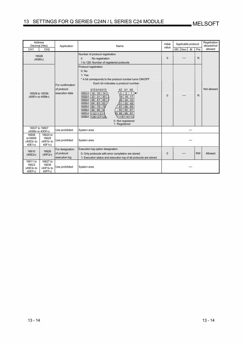
13 - 14 13 - 14
MELSOFT13 SETTINGS FOR Q SERIES C24N / L SERIES C24 MODULE
Address
Decimal (Hex) Applicable protocol
CH1 CH2 Application Name
Initial value
MC Non Bi Pre
Registration allowed/not
allowed Number of protocol registration 16528
(4090H) 0 : No registration 1 to 128: Number of registered protocols
0 — R
Protocol registration 0: No 1: Yes * A bit corresponds to the protocol number turns ON/OFF.
16529 to 16536 (4091H to 4098H)
For confirmation of protocol execution data 1234141516
29303132 17181945464748 333435
626364 495051787980 656667949596 818283
9798991001101111121131141151161261271284098H
4097H
4096H
4095H
4094H
4093H
4092H
4091H
b15 b14 b13 b2 b1 b0
Each bit indicates a protocol number.
0: Not registered1: Registered
0 — R
Not allowed
16537 to 16607 (4099H to 40DFH) Use prohibited System area —
16608 to16609
(40E0H to 40E1H)
16624 to 16625
(40F0H to 40F1H)
Use prohibited System area —
Execution log option designation 16610
(40E2H) 16626
(40F2H)
For designation of protocol execution log
0: Only protocols with error completion are stored. 1: Execution status and execution log of all protocols are stored.
0 — RW Allowed
16611 to 16623
(40E3H to 40EFH)
16627 to 16639
(40F3H to 40FFH)
Use prohibited System area —
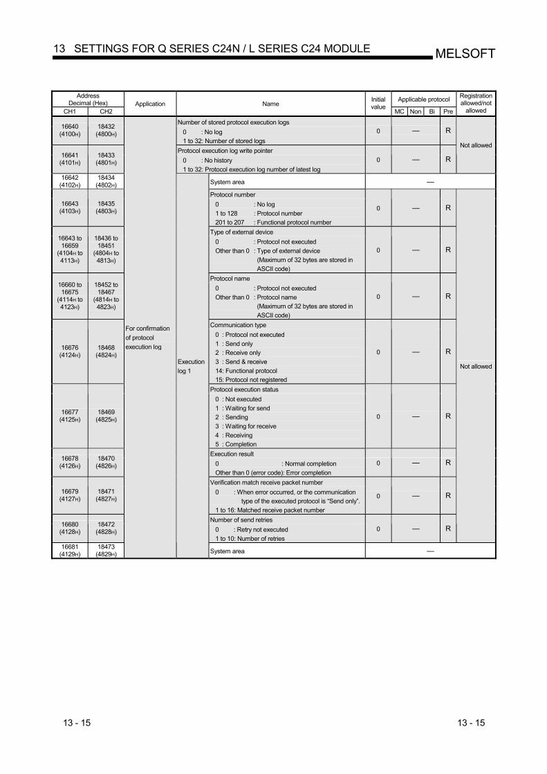
13 - 15 13 - 15
MELSOFT13 SETTINGS FOR Q SERIES C24N / L SERIES C24 MODULE
Address
Decimal (Hex) Applicable protocol
CH1 CH2 Application Name
Initial value
MC Non Bi Pre
Registration allowed/not
allowed Number of stored protocol execution logs 16640
(4100H) 18432
(4800H) 0 : No log 1 to 32: Number of stored logs
0 — R
Protocol execution log write pointer 16641
(4101H) 18433
(4801H) 0 : No history 1 to 32: Protocol execution log number of latest log
0 — R
Not allowed
16642 (4102H)
18434 (4802H) System area —
Protocol number 16643
(4103H) 18435
(4803H) 0 : No log 1 to 128 : Protocol number 201 to 207 : Functional protocol number
0 — R
Type of external device 16643 to 16659
(4104H to 4113H)
18436 to 18451
(4804H to 4813H)
0 : Protocol not executed Other than 0 : Type of external device (Maximum of 32 bytes are stored in
ASCII code)
0 — R
Protocol name 16660 to 16675
(4114H to 4123H)
18452 to 18467
(4814H to 4823H)
0 : Protocol not executed Other than 0 : Protocol name (Maximum of 32 bytes are stored in
ASCII code)
0 — R
Communication type
16676 (4124H)
18468 (4824H)
0 : Protocol not executed 1 : Send only 2 : Receive only 3 : Send & receive 14: Functional protocol 15: Protocol not registered
0 — R
Protocol execution status
16677 (4125H)
18469 (4825H)
0 : Not executed 1 : Waiting for send 2 : Sending 3 : Waiting for receive 4 : Receiving 5 : Completion
0 — R
Execution result 16678
(4126H) 18470
(4826H) 0 : Normal completion Other than 0 (error code): Error completion
0 — R
Verification match receive packet number 16679
(4127H) 18471
(4827H) 0 : When error occurred, or the communication
type of the executed protocol is “Send only”. 1 to 16: Matched receive packet number
0 — R
Number of send retries 16680
(4128H) 18472
(4828H) 0 : Retry not executed 1 to 10: Number of retries
0 — R
Not allowed
16681 (4129H)
18473 (4829H)
For confirmation of protocol execution log
Execution log 1
System area —
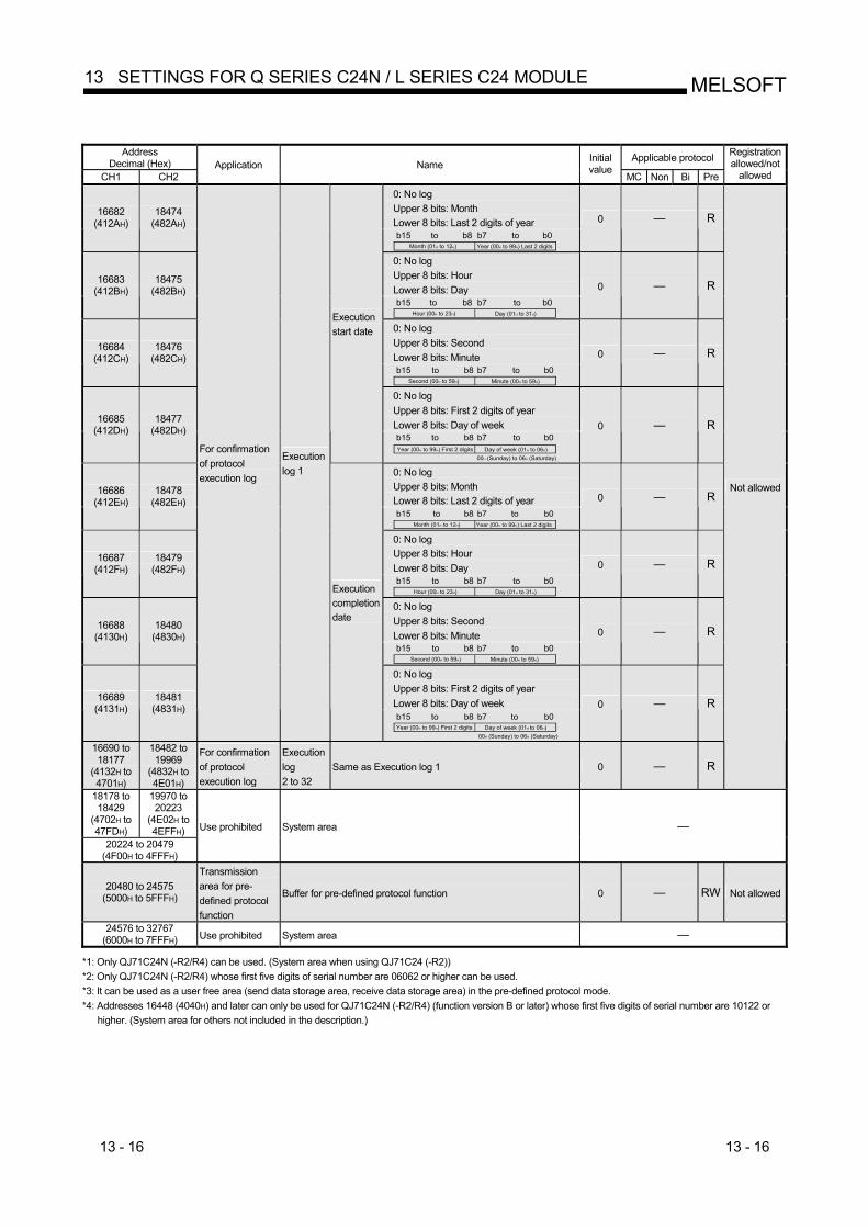
13 - 16 13 - 16
MELSOFT13 SETTINGS FOR Q SERIES C24N / L SERIES C24 MODULE
Address
Decimal (Hex) Applicable protocol
CH1 CH2 Application Name
Initial value
MC Non Bi Pre
Registration allowed/not
allowed 0: No log Upper 8 bits: Month Lower 8 bits: Last 2 digits of year
16682 (412AH)
18474 (482AH)
b15 b8 b7 b0Year (00H to 99H) Last 2 digits Month (01H to 12H)
toto
0 — R
0: No log Upper 8 bits: Hour Lower 8 bits: Day
16683 (412BH)
18475 (482BH)
b15 b8 b7 b0Day (01H to 31H) Hour (00H to 23H)
toto
0 — R
0: No log Upper 8 bits: Second Lower 8 bits: Minute
16684 (412CH)
18476 (482CH)
b15 b8 b7 b0Minute (00H to 59H) Second (00H to 59H)
toto
0 — R
0: No log Upper 8 bits: First 2 digits of year Lower 8 bits: Day of week 16685
(412DH) 18477
(482DH)
Execution start date
b15 b8 b7 b0Day of week (01H to 06H) Year (00H to 99H) First 2 digits
00H (Sunday) to 06H (Saturday)
toto
0 — R
0: No log Upper 8 bits: Month Lower 8 bits: Last 2 digits of year
16686 (412EH)
18478 (482EH)
b15 b8 b7 b0Year (00H to 99H) Last 2 digits Month (01H to 12H)
toto
0 — R
0: No log Upper 8 bits: Hour Lower 8 bits: Day
16687 (412FH)
18479 (482FH)
b15 b8 b7 b0Day (01H to 31H) Hour (00H to 23H)
toto
0 — R
0: No log Upper 8 bits: Second Lower 8 bits: Minute
16688 (4130H)
18480 (4830H)
b15 b8 b7 b0Minute (00H to 59H) Second (00H to 59H)
to to
0 — R
0: No log Upper 8 bits: First 2 digits of year Lower 8 bits: Day of week 16689
(4131H) 18481
(4831H)
For confirmation of protocol execution log
Execution log 1
Execution completion date
b15 b8 b7 b0Day of week (01H to 06H) Year (00H to 99H) First 2 digits
00H (Sunday) to 06H (Saturday)
to to
0 — R
16690 to 18177
(4132H to 4701H)
18482 to 19969
(4832H to 4E01H)
For confirmation of protocol execution log
Execution log 2 to 32
Same as Execution log 1 0 — R
Not allowed
18178 to 18429
(4702H to 47FDH)
19970 to 20223
(4E02H to 4EFFH)
20224 to 20479 (4F00H to 4FFFH)
Use prohibited System area —
20480 to 24575 (5000H to 5FFFH)
Transmission area for pre-defined protocol function
Buffer for pre-defined protocol function 0 — RW Not allowed
24576 to 32767 (6000H to 7FFFH) Use prohibited System area —
*1: Only QJ71C24N (-R2/R4) can be used. (System area when using QJ71C24 (-R2)) *2: Only QJ71C24N (-R2/R4) whose first five digits of serial number are 06062 or higher can be used. *3: It can be used as a user free area (send data storage area, receive data storage area) in the pre-defined protocol mode. *4: Addresses 16448 (4040H) and later can only be used for QJ71C24N (-R2/R4) (function version B or later) whose first five digits of serial number are 10122 or higher. (System area for others not included in the description.)
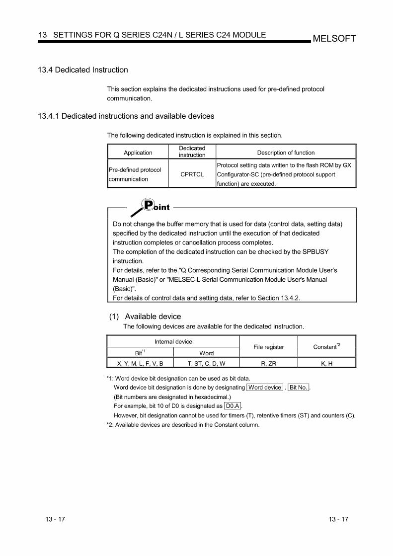
13 - 17 13 - 17
MELSOFT13 SETTINGS FOR Q SERIES C24N / L SERIES C24 MODULE
13.4 Dedicated Instruction
This section explains the dedicated instructions used for pre-defined protocol communication.
13.4.1 Dedicated instructions and available devices
The following dedicated instruction is explained in this section.
Application Dedicated instruction Description of function
Pre-defined protocol communication
CPRTCL Protocol setting data written to the flash ROM by GX Configurator-SC (pre-defined protocol support function) are executed.
Do not change the buffer memory that is used for data (control data, setting data) specified by the dedicated instruction until the execution of that dedicated instruction completes or cancellation process completes. The completion of the dedicated instruction can be checked by the SPBUSY instruction. For details, refer to the "Q Corresponding Serial Communication Module User’s Manual (Basic)" or "MELSEC-L Serial Communication Module User's Manual (Basic)". For details of control data and setting data, refer to Section 13.4.2.
(1) Available device
The following devices are available for the dedicated instruction.
Internal device
Bit*1 Word File register Constant*2
X, Y, M, L, F, V, B T, ST, C, D, W R, ZR K, H
*1: Word device bit designation can be used as bit data. Word device bit designation is done by designating Word device . Bit No. . (Bit numbers are designated in hexadecimal.) For example, bit 10 of D0 is designated as D0.A . However, bit designation cannot be used for timers (T), retentive timers (ST) and counters (C).
*2: Available devices are described in the Constant column.
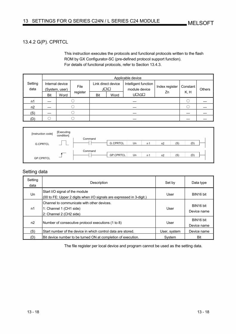
13 - 18 13 - 18
MELSOFT13 SETTINGS FOR Q SERIES C24N / L SERIES C24 MODULE
13.4.2 G(P). CPRTCL
This instruction executes the protocols and functional protocols written to the flash ROM by GX Configurator-SC (pre-defined protocol support function). For details of functional protocols, refer to Section 13.4.3.
Applicable device Internal device (System, user)
Link direct device J \
Setting data
Bit Word
File register
Bit Word
Intelligent function module device
U \G
Index register Zn
ConstantK, H
Others
n1 — — — n2 — — — (S) — — — — (D) — — —
Command
Command
[Instruction code]
G.CPRTCL
GP.CPRTCL
n 1 (S) (D) n2G.CPRTCL Un
n 1 (S) (D) n2GP.CPRTCL Un
[Executing condition]
Setting data
Setting data
Description Set by Data type
Un Start I/O signal of the module (00 to FE: Upper 2 digits when I/O signals are expressed in 3-digit.)
User BIN16 bit
n1 Channel to communicate with other devices. 1: Channel 1 (CH1 side) 2: Channel 2 (CH2 side)
User BIN16 bit
Device name
n2 Number of consecutive protocol executions (1 to 8) User BIN16 bit
Device name (S) Start number of the device in which control data are stored. User, system Device name (D) Bit device number to be turned ON at completion of execution. System Bit
The file register per local device and program cannot be used as the setting data.
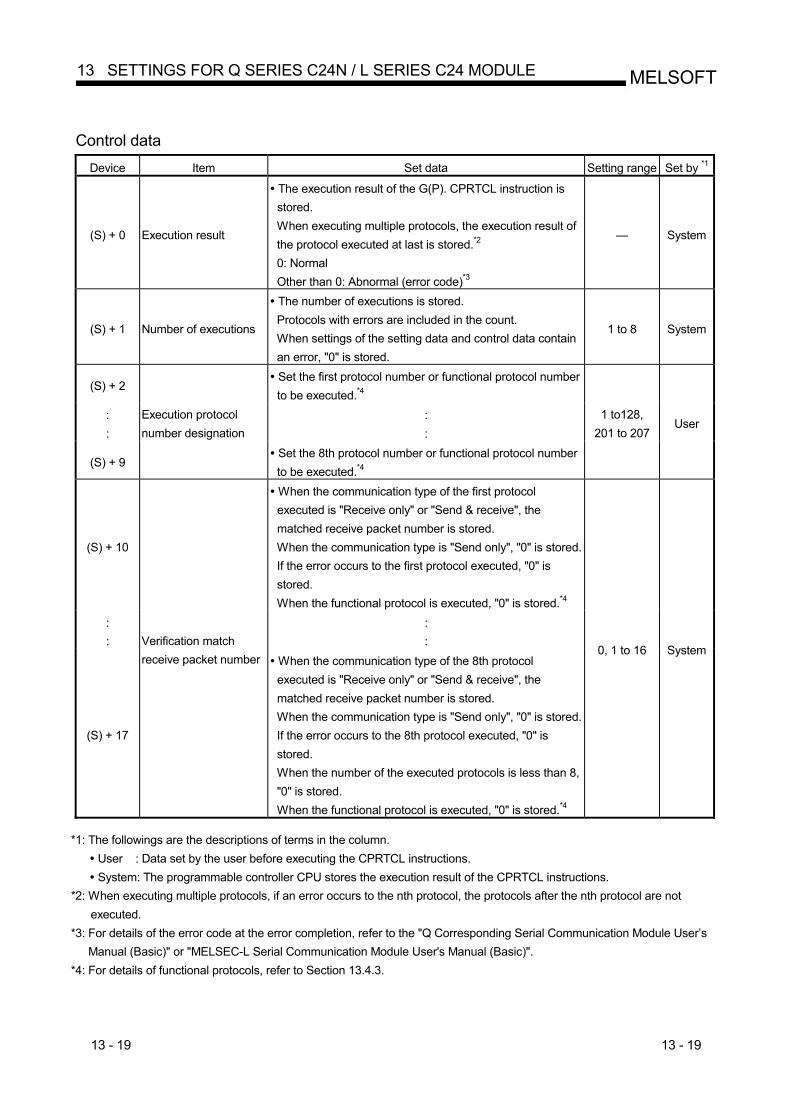
13 - 19 13 - 19
MELSOFT13 SETTINGS FOR Q SERIES C24N / L SERIES C24 MODULE
Control data
Device Item Set data Setting range Set by *1
(S) + 0 Execution result
The execution result of the G(P). CPRTCL instruction is stored. When executing multiple protocols, the execution result of the protocol executed at last is stored.*2 0: Normal Other than 0: Abnormal (error code)*3
— System
(S) + 1 Number of executions
The number of executions is stored. Protocols with errors are included in the count. When settings of the setting data and control data contain an error, "0" is stored.
1 to 8 System
(S) + 2 Set the first protocol number or functional protocol number to be executed.*4
: :
: :
(S) + 9
Execution protocol number designation
Set the 8th protocol number or functional protocol number to be executed.*4
1 to128, 201 to 207
User
(S) + 10
When the communication type of the first protocol executed is "Receive only" or "Send & receive", the matched receive packet number is stored. When the communication type is "Send only", "0" is stored. If the error occurs to the first protocol executed, "0" is stored. When the functional protocol is executed, "0" is stored.*4
: :
: :
(S) + 17
Verification match receive packet number When the communication type of the 8th protocol
executed is "Receive only" or "Send & receive", the matched receive packet number is stored. When the communication type is "Send only", "0" is stored. If the error occurs to the 8th protocol executed, "0" is stored. When the number of the executed protocols is less than 8, "0" is stored. When the functional protocol is executed, "0" is stored.*4
0, 1 to 16 System
*1: The followings are the descriptions of terms in the column.
User : Data set by the user before executing the CPRTCL instructions. System: The programmable controller CPU stores the execution result of the CPRTCL instructions.
*2: When executing multiple protocols, if an error occurs to the nth protocol, the protocols after the nth protocol are not executed.
*3: For details of the error code at the error completion, refer to the "Q Corresponding Serial Communication Module User’s Manual (Basic)" or "MELSEC-L Serial Communication Module User's Manual (Basic)".
*4: For details of functional protocols, refer to Section 13.4.3.
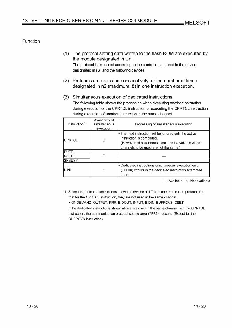
13 - 20 13 - 20
MELSOFT13 SETTINGS FOR Q SERIES C24N / L SERIES C24 MODULE
Function
(1) The protocol setting data written to the flash ROM are executed by the module designated in Un. The protocol is executed according to the control data stored in the device designated in (S) and the following devices.
(2) Protocols are executed consecutively for the number of times
designated in n2 (maximum: 8) in one instruction execution.
(3) Simultaneous execution of dedicated instructions The following table shows the processing when executing another instruction during execution of the CPRTCL instruction or executing the CPRTCL instruction during execution of another instruction in the same channel.
Instruction*1 Availability of simultaneous
execution Processing of simultaneous execution
CPRTCL
The next instruction will be ignored until the active instruction is completed. (However, simultaneous execution is available when channels to be used are not the same.)
PUTE GETE SPBUSY
⎯
UINI Dedicated instructions simultaneous execution error (7FF0H) occurs in the dedicated instruction attempted later.
: Available : Not available
*1: Since the dedicated instructions shown below use a different communication protocol from that for the CPRTCL instruction, they are not used in the same channel. ONDEMAND, OUTPUT, PRR, BIDOUT, INPUT, BIDIN, BUFRCVS, CSET
If the dedicated instructions shown above are used in the same channel with the CPRTCL instruction, the communication protocol setting error (7FF2H) occurs. (Except for the BUFRCVS instruction)
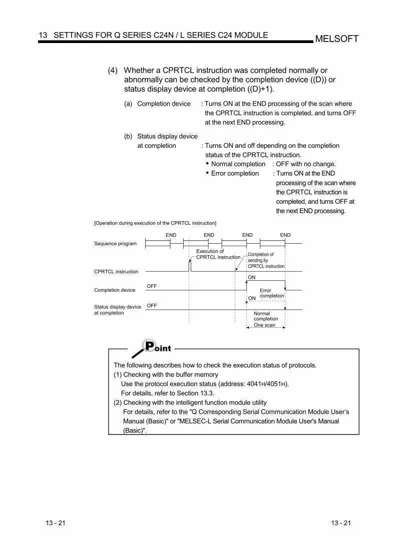
13 - 21 13 - 21
MELSOFT13 SETTINGS FOR Q SERIES C24N / L SERIES C24 MODULE
(4) Whether a CPRTCL instruction was completed normally or
abnormally can be checked by the completion device ((D)) or status display device at completion ((D)+1).
(a) Completion device : Turns ON at the END processing of the scan where
the CPRTCL instruction is completed, and turns OFF at the next END processing.
(b) Status display device
at completion : Turns ON and off depending on the completion status of the CPRTCL instruction. Normal completion : OFF with no change. Error completion : Turns ON at the END
processing of the scan where the CPRTCL instruction is completed, and turns OFF at the next END processing.
Sequence program
CPRTCL instruction
Completion device
Status display deviceat completion
Execution of CPRTCL instruction Completion of
sending byCPRTCL instruction
ON
ONErrorcompletion
NormalcompletionOne scan
OFF
ENDENDENDEND
[Operation during execution of the CPRTCL instruction]
OFF
The following describes how to check the execution status of protocols. (1) Checking with the buffer memory
Use the protocol execution status (address: 4041H/4051H). For details, refer to Section 13.3.
(2) Checking with the intelligent function module utility For details, refer to the "Q Corresponding Serial Communication Module User’s Manual (Basic)" or "MELSEC-L Serial Communication Module User's Manual (Basic)".
13 - 22 13 - 22
MELSOFT13 SETTINGS FOR Q SERIES C24N / L SERIES C24 MODULE
Error
(1) When a dedicated instruction is completed abnormally, the status display device at completion ((D)+1) turns ON and the error code is stored in the execution result ((S)+0). In case of operation errors, the error flag (SM0) turns ON and the error code is stored in the SD0. Refer to the following manuals according to the error code, and check and correct the error. <Error code> 4FFFH or less : QCPU (Q Mode) User's Manual (Hardware Design, Maintenance and Inspection) MELSEC-L CPU Module User's Manual
(Hardware Design, Maintenance and Inspection) 7000H or more : Q Corresponding Serial Communication Module User’s Manual
(Basic) MELSEC-L Serial Communication Module User's Manual
(Basic) Program example
For the program example of the CPRTCL instruction, refer to Section 13.5.3.
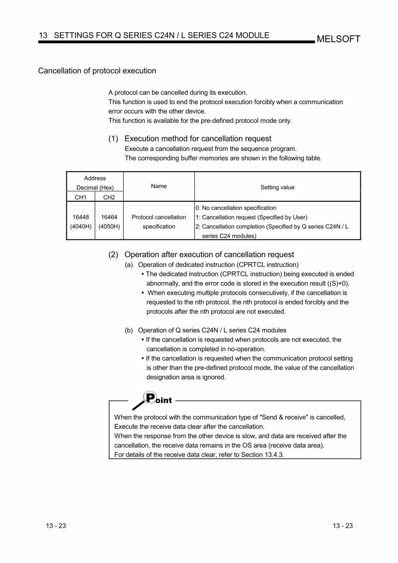
13 - 23 13 - 23
MELSOFT13 SETTINGS FOR Q SERIES C24N / L SERIES C24 MODULE
Cancellation of protocol execution
A protocol can be cancelled during its execution. This function is used to end the protocol execution forcibly when a communication error occurs with the other device. This function is available for the pre-defined protocol mode only.
(1) Execution method for cancellation request
Execute a cancellation request from the sequence program. The corresponding buffer memories are shown in the following table.
Address
Decimal (Hex) CH1 CH2
Name Setting value
16448 (4040H)
16464 (4050H)
Protocol cancellation specification
0: No cancellation specification 1: Cancellation request (Specified by User) 2: Cancellation completion (Specified by Q series C24N / L
series C24 modules)
(2) Operation after execution of cancellation request
(a) Operation of dedicated instruction (CPRTCL instruction) The dedicated instruction (CPRTCL instruction) being executed is ended abnormally, and the error code is stored in the execution result ((S)+0).
When executing multiple protocols consecutively, if the cancellation is requested to the nth protocol, the nth protocol is ended forcibly and the protocols after the nth protocol are not executed.
(b) Operation of Q series C24N / L series C24 modules
If the cancellation is requested when protocols are not executed, the cancellation is completed in no-operation.
If the cancellation is requested when the communication protocol setting is other than the pre-defined protocol mode, the value of the cancellation designation area is ignored.
When the protocol with the communication type of "Send & receive" is cancelled, Execute the receive data clear after the cancellation. When the response from the other device is slow, and data are received after the cancellation, the receive data remains in the OS area (receive data area). For details of the receive data clear, refer to Section 13.4.3.
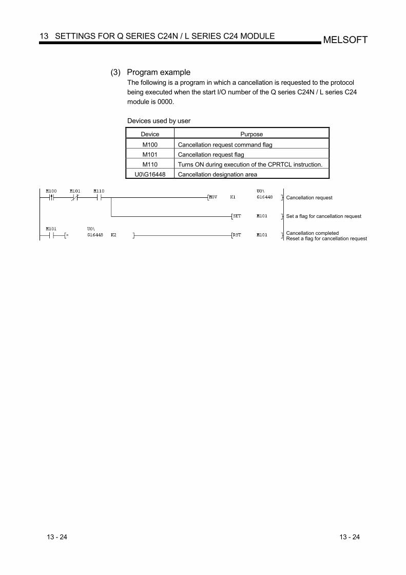
13 - 24 13 - 24
MELSOFT13 SETTINGS FOR Q SERIES C24N / L SERIES C24 MODULE
(3) Program example
The following is a program in which a cancellation is requested to the protocol being executed when the start I/O number of the Q series C24N / L series C24 module is 0000.
Devices used by user
Device Purpose
M100 Cancellation request command flag M101 Cancellation request flag M110 Turns ON during execution of the CPRTCL instruction.
U0\G16448 Cancellation designation area
Cancellation request
Set a flag for cancellation request
Cancellation completedReset a flag for cancellation request
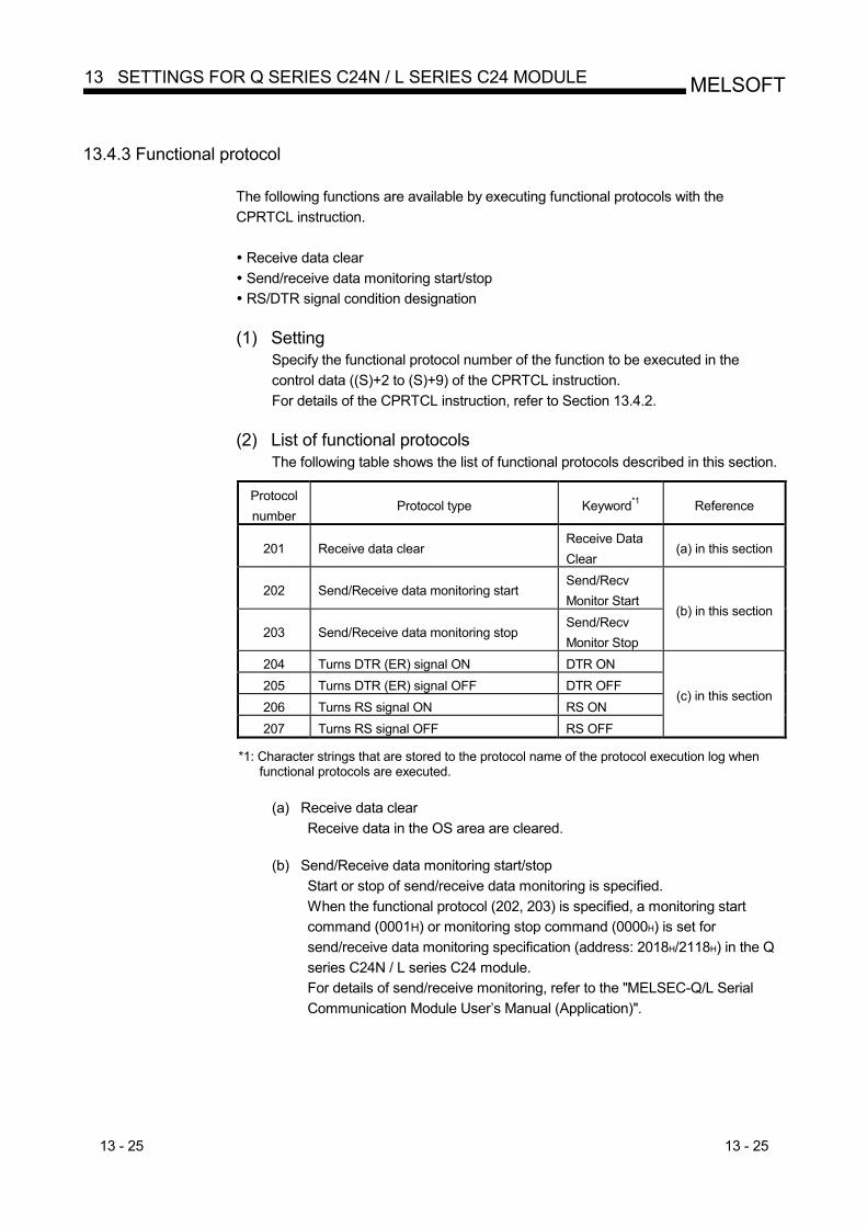
13 - 25 13 - 25
MELSOFT13 SETTINGS FOR Q SERIES C24N / L SERIES C24 MODULE
13.4.3 Functional protocol
The following functions are available by executing functional protocols with the CPRTCL instruction. Receive data clear Send/receive data monitoring start/stop RS/DTR signal condition designation
(1) Setting
Specify the functional protocol number of the function to be executed in the control data ((S)+2 to (S)+9) of the CPRTCL instruction. For details of the CPRTCL instruction, refer to Section 13.4.2.
(2) List of functional protocols
The following table shows the list of functional protocols described in this section.
Protocol number
Protocol type Keyword*1 Reference
201 Receive data clear Receive Data Clear
(a) in this section
202 Send/Receive data monitoring start Send/Recv Monitor Start
203 Send/Receive data monitoring stop Send/Recv Monitor Stop
(b) in this section
204 Turns DTR (ER) signal ON DTR ON 205 Turns DTR (ER) signal OFF DTR OFF 206 Turns RS signal ON RS ON 207 Turns RS signal OFF RS OFF
(c) in this section
*1: Character strings that are stored to the protocol name of the protocol execution log when
functional protocols are executed.
(a) Receive data clear Receive data in the OS area are cleared.
(b) Send/Receive data monitoring start/stop
Start or stop of send/receive data monitoring is specified. When the functional protocol (202, 203) is specified, a monitoring start command (0001H) or monitoring stop command (0000H) is set for send/receive data monitoring specification (address: 2018H/2118H) in the Q series C24N / L series C24 module. For details of send/receive monitoring, refer to the "MELSEC-Q/L Serial Communication Module User’s Manual (Application)".
13 - 26 13 - 26
MELSOFT13 SETTINGS FOR Q SERIES C24N / L SERIES C24 MODULE
(c) RS/DTR signal status specification
ON/OFF status of the RS/DTR signal is specified. When the functional protocol (204 to 207) is executed, corresponding bits of the RS/DTR signal status specification (address: 92H/132H) are turned ON/OFF in the Q series C24N / L series C24 module. For details of RS/DTR signal status specification, refer to the "Q Corresponding Serial Communication Module User’s Manual (Basic)" or "MELSEC-L Serial Communication Module User's Manual (Basic)".
13 - 27 13 - 27
MELSOFT13 SETTINGS FOR Q SERIES C24N / L SERIES C24 MODULE
13.5 Programming example
This section explains the programming examples and setting examples of the pre-defined protocol function. GX Developer and pre-defined protocol support function of GX Configurator-SC are used for settings. Serial communication module QJ71C24N and Mitsubishi inverter (FREQROL-A700, described as inverter or FR-A700 hereafter) as a connection target device are used in this setting example.
13.5.1 System configuration/wiring example
The system configuration and wiring example are as follows.
(1) System configuration example. QJ71C24N is mounted at the slot 0 on the base unit, and connected 1:1 with the other device through the RS-422/485 line using CH2. For details of system configuration, refer to the "Q Corresponding Serial Communication Module User’s Manual (Basic)".
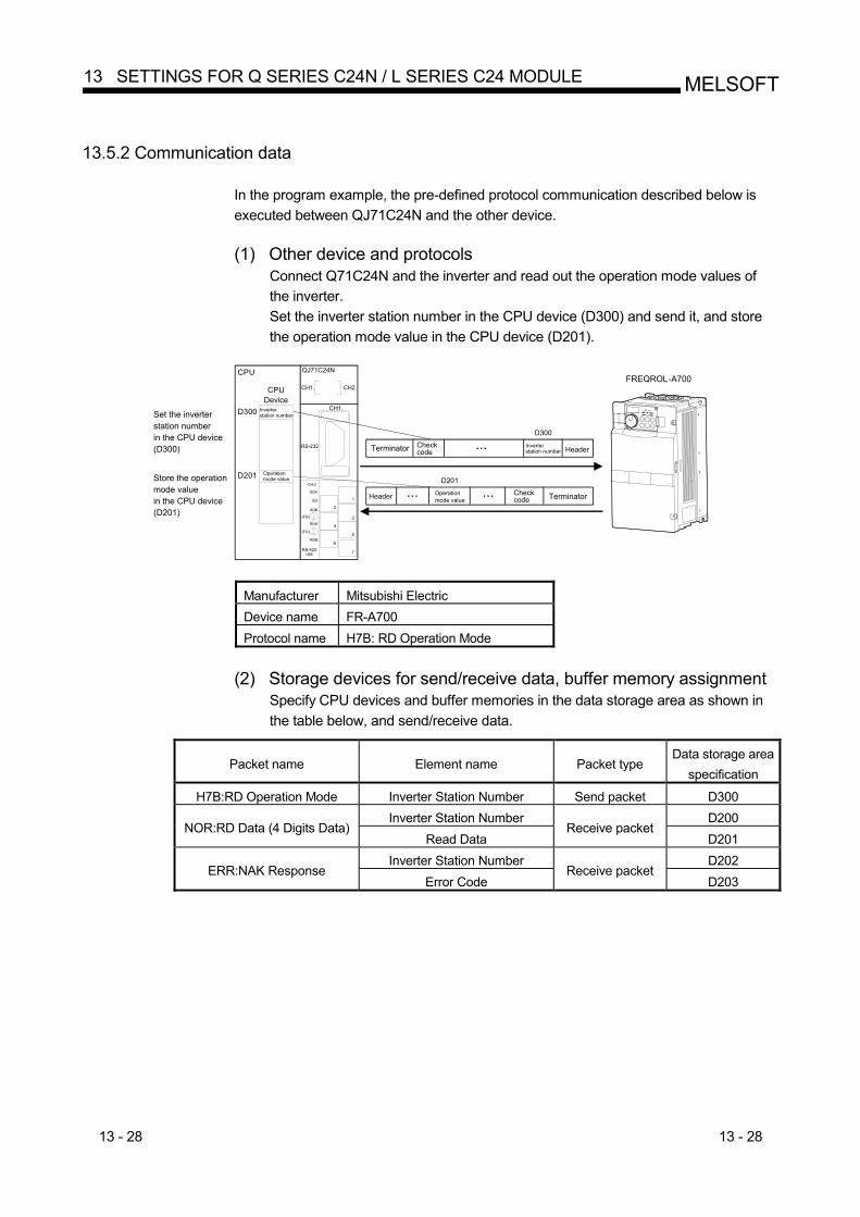
13 - 28 13 - 28
MELSOFT13 SETTINGS FOR Q SERIES C24N / L SERIES C24 MODULE
13.5.2 Communication data
In the program example, the pre-defined protocol communication described below is executed between QJ71C24N and the other device.
(1) Other device and protocols
Connect Q71C24N and the inverter and read out the operation mode values of the inverter. Set the inverter station number in the CPU device (D300) and send it, and store the operation mode value in the CPU device (D201).
RS-232
CH.2
SDA
SG
SDB
(FG)
RDA
(FG)
RDB
RS-422 /485
CH1.
CH2.CH1.
2
1
3
4
5
6
7
QJ71C24NCPU
D300
D201
Set the inverterstation numberin the CPU device(D300)
Operation mode value
Inverter station number
FREQROL-A700CPU
Device
Checkcode
D300
Inverterstation number
Header Checkcode
D201
Operationmode value
Store the operationmode valuein the CPU device(D201)
Terminator Header
Terminator
Manufacturer Mitsubishi Electric Device name FR-A700 Protocol name H7B: RD Operation Mode
(2) Storage devices for send/receive data, buffer memory assignment
Specify CPU devices and buffer memories in the data storage area as shown in the table below, and send/receive data.
Packet name Element name Packet type Data storage area
specification
H7B:RD Operation Mode Inverter Station Number Send packet D300 Inverter Station Number D200
NOR:RD Data (4 Digits Data) Read Data
Receive packet D201
Inverter Station Number D202 ERR:NAK Response
Error Code Receive packet
D203
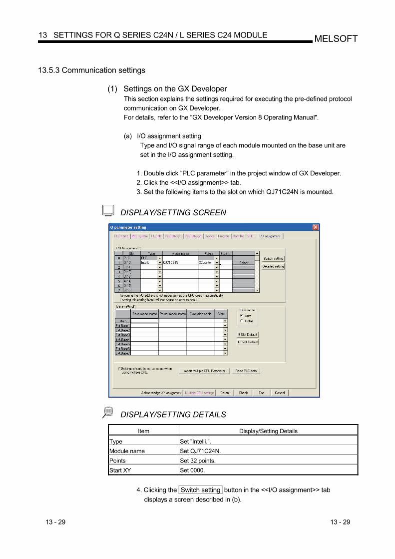
13 - 29 13 - 29
MELSOFT13 SETTINGS FOR Q SERIES C24N / L SERIES C24 MODULE
13.5.3 Communication settings
(1) Settings on the GX Developer This section explains the settings required for executing the pre-defined protocol communication on GX Developer. For details, refer to the "GX Developer Version 8 Operating Manual".
(a) I/O assignment setting
Type and I/O signal range of each module mounted on the base unit are set in the I/O assignment setting.
1. Double click "PLC parameter" in the project window of GX Developer. 2. Click the <<I/O assignment>> tab. 3. Set the following items to the slot on which QJ71C24N is mounted.
DISPLAY/SETTING SCREEN
DISPLAY/SETTING DETAILS Item Display/Setting Details
Type Set "Intelli.". Module name Set QJ71C24N. Points Set 32 points. Start XY Set 0000.
4. Clicking the Switch setting button in the <<I/O assignment>> tab
displays a screen described in (b).
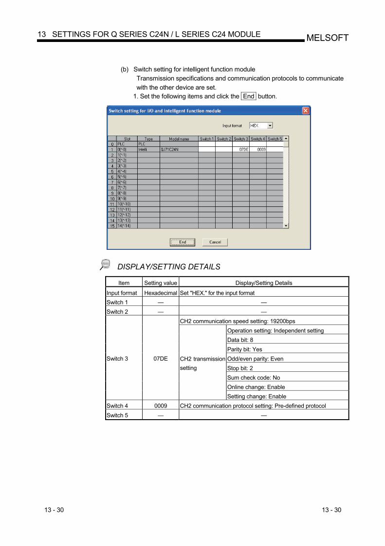
13 - 30 13 - 30
MELSOFT13 SETTINGS FOR Q SERIES C24N / L SERIES C24 MODULE
(b) Switch setting for intelligent function module
Transmission specifications and communication protocols to communicate with the other device are set.
1. Set the following items and click the End button.
DISPLAY/SETTING DETAILS Item Setting value Display/Setting Details
Input format Hexadecimal Set "HEX." for the input format Switch 1 — — Switch 2 — —
CH2 communication speed setting: 19200bps Operation setting: Independent setting Data bit: 8 Parity bit: Yes Odd/even parity: Even Stop bit: 2 Sum check code: No Online change: Enable
Switch 3 07DE CH2 transmission setting
Setting change: Enable Switch 4 0009 CH2 communication protocol setting: Pre-defined protocol Switch 5 — —
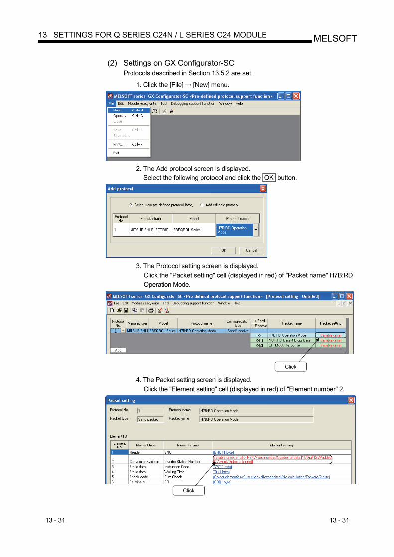
13 - 31 13 - 31
MELSOFT13 SETTINGS FOR Q SERIES C24N / L SERIES C24 MODULE
(2) Settings on GX Configurator-SC
Protocols described in Section 13.5.2 are set. 1. Click the [File] [New] menu.
2. The Add protocol screen is displayed.
Select the following protocol and click the OK button.
3. The Protocol setting screen is displayed.
Click the "Packet setting" cell (displayed in red) of "Packet name" H7B:RD Operation Mode.
Click 4. The Packet setting screen is displayed.
Click the "Element setting" cell (displayed in red) of "Element number" 2.
Click
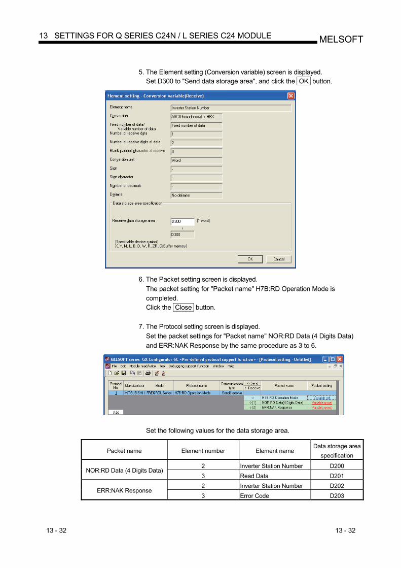
13 - 32 13 - 32
MELSOFT13 SETTINGS FOR Q SERIES C24N / L SERIES C24 MODULE
5. The Element setting (Conversion variable) screen is displayed.
Set D300 to "Send data storage area", and click the OK button.
6. The Packet setting screen is displayed.
The packet setting for "Packet name" H7B:RD Operation Mode is completed. Click the Close button.
7. The Protocol setting screen is displayed. Set the packet settings for "Packet name" NOR:RD Data (4 Digits Data) and ERR:NAK Response by the same procedure as 3 to 6.
Set the following values for the data storage area.
Packet name Element number Element name Data storage area
specification
2 Inverter Station Number D200 NOR:RD Data (4 Digits Data)
3 Read Data D201 2 Inverter Station Number D202
ERR:NAK Response 3 Error Code D203
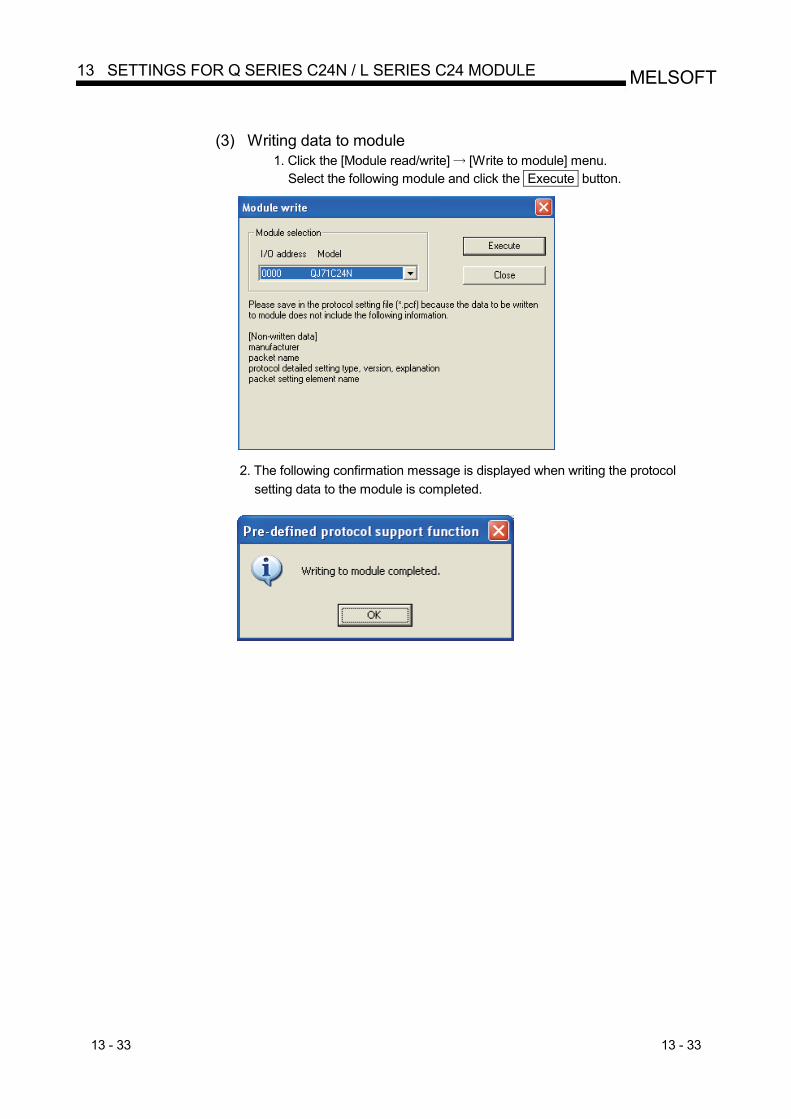
13 - 33 13 - 33
MELSOFT13 SETTINGS FOR Q SERIES C24N / L SERIES C24 MODULE
(3) Writing data to module
1. Click the [Module read/write] [Write to module] menu. Select the following module and click the Execute button.
2. The following confirmation message is displayed when writing the protocol
setting data to the module is completed.
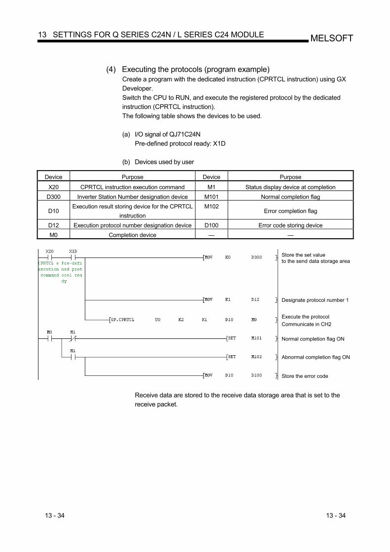
13 - 34 13 - 34
MELSOFT13 SETTINGS FOR Q SERIES C24N / L SERIES C24 MODULE
(4) Executing the protocols (program example)
Create a program with the dedicated instruction (CPRTCL instruction) using GX Developer. Switch the CPU to RUN, and execute the registered protocol by the dedicated instruction (CPRTCL instruction). The following table shows the devices to be used.
(a) I/O signal of QJ71C24N
Pre-defined protocol ready: X1D
(b) Devices used by user
Device Purpose Device Purpose
X20 CPRTCL instruction execution command M1 Status display device at completion D300 Inverter Station Number designation device M101 Normal completion flag
D10 Execution result storing device for the CPRTCL
instruction M102
Error completion flag
D12 Execution protocol number designation device D100 Error code storing device M0 Completion device — —
Store the set valueto the send data storage area
Designate protocol number 1
Execute the protocolCommunicate in CH2
Normal completion flag ON
Abnormal completion flag ON
Store the error code
Receive data are stored to the receive data storage area that is set to the receive packet.
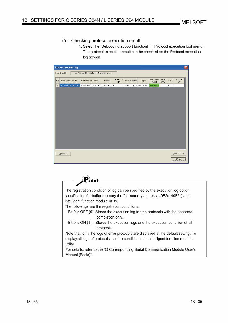
13 - 35 13 - 35
MELSOFT13 SETTINGS FOR Q SERIES C24N / L SERIES C24 MODULE
(5) Checking protocol execution result
1. Select the [Debugging support function] [Protocol execution log] menu. The protocol execution result can be checked on the Protocol execution log screen.
The registration condition of log can be specified by the execution log option specification for buffer memory (buffer memory address: 40E2H, 40F2H) and intelligent function module utility. The followings are the registration conditions.
Bit 0 is OFF (0): Stores the execution log for the protocols with the abnormal completion only.
Bit 0 is ON (1) : Stores the execution logs and the execution condition of all protocols.
Note that, only the logs of error protocols are displayed at the default setting. To display all logs of protocols, set the condition in the intelligent function module utility. For details, refer to the "Q Corresponding Serial Communication Module User’s Manual (Basic)".
13 - 36 13 - 36
MELSOFT13 SETTINGS FOR Q SERIES C24N / L SERIES C24 MODULE
MEMO
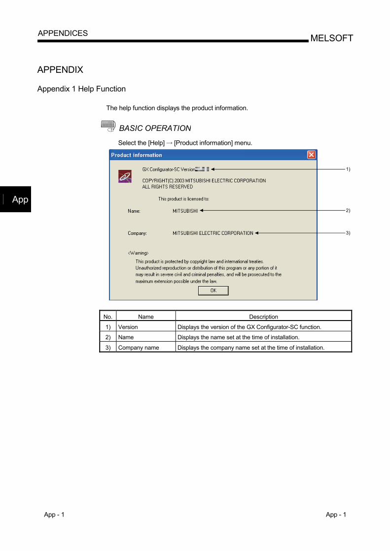
App - 1 App - 1
MELSOFTAPPENDICES
APPENDIX
Appendix 1 Help Function
The help function displays the product information.
BASIC OPERATION Select the [Help] [Product information] menu.
1)
2)
3)
No. Name Description
1) Version Displays the version of the GX Configurator-SC function.
2) Name Displays the name set at the time of installation.
3) Company name Displays the company name set at the time of installation.
App
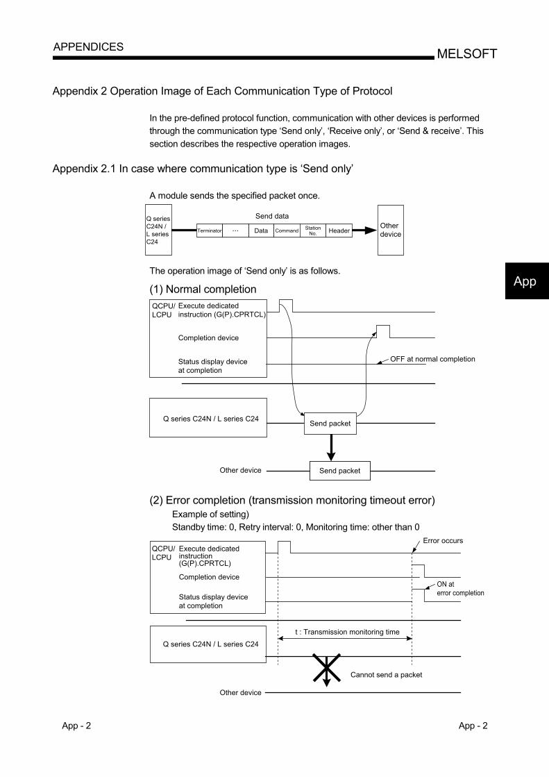
App - 2 App - 2
MELSOFTAPPENDICES
Appendix 2 Operation Image of Each Communication Type of Protocol
In the pre-defined protocol function, communication with other devices is performed through the communication type ‘Send only’, ‘Receive only’, or ‘Send & receive’. This section describes the respective operation images.
Appendix 2.1 In case where communication type is ‘Send only’
A module sends the specified packet once.
Q seriesC24N / L seriesC24
Terminator Data Command StationNo.
Send dataOtherdeviceHeader
The operation image of ‘Send only’ is as follows.
(1) Normal completion
Q series C24N / L series C24
Other device
Execute dedicatedinstruction (G(P).CPRTCL)
Completion device
Send packet
Send packet
Status display deviceat completion
OFF at normal completion
QCPU/LCPU
(2) Error completion (transmission monitoring timeout error) Example of setting) Standby time: 0, Retry interval: 0, Monitoring time: other than 0
Q series C24N / L series C24
Other device
Execute dedicatedinstruction(G(P).CPRTCL)
Completion device
Status display deviceat completion
t : Transmission monitoring time
Cannot send a packet
Error occurs
ON aterror completion
QCPU/LCPU
App
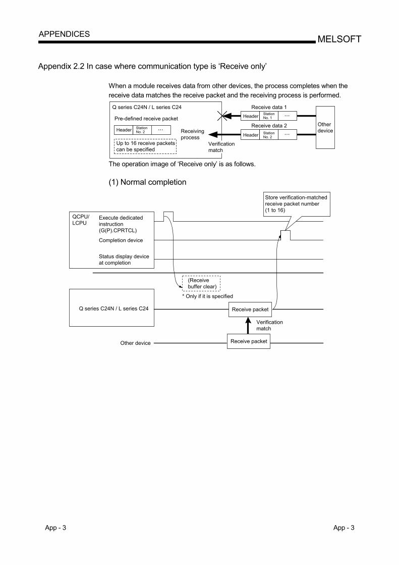
App - 3 App - 3
MELSOFTAPPENDICES
Appendix 2.2 In case where communication type is ‘Receive only’
When a module receives data from other devices, the process completes when the receive data matches the receive packet and the receiving process is performed.
Q series C24N / L series C24StationNo. 1
Receivingprocess
StationNo. 2
Up to 16 receive packetscan be specified
Receive data 2
Receive data 1Header
HeaderStationNo. 2Header
Otherdevice
Pre-defined receive packet
Verificationmatch
The operation image of ‘Receive only’ is as follows. (1) Normal completion
Q series C24N / L series C24
Other device
Execute dedicatedinstruction(G(P).CPRTCL)
Completion device
Receive packet
Receive packet
Status display deviceat completion
QCPU/LCPU
* Only if it is specified
Verificationmatch
Store verification-matchedreceive packet number(1 to 16)
(Receivebuffer clear)
App - 4 App - 4
MELSOFTAPPENDICES
(2) Error completion (receive wait timeout error)
Q series C24N / L series C24
QCPU/LCPU
Execute dedicatedinstruction(G(P).CPRTCL)
Completion device
Status display deviceat completion
t: Receive waiting time
ON at error completion
* Only if it is specified
(Receivebuffer clear)
Receive packetReceive packetOther device
Error occurs
Verificationmismatch
When variables are included in receive packet elements, variable parts are not verified.
With multiple receive packet specifications, receive data are verified with registered receive packet information starting from information of the first registered packet, in the registration order. Once the receive data match one of them, the receiving process is performed and the following verification is cancelled.
The number of a receive packet which is matched in the verification is stored in the control data of the dedicated instruction (CPRTCL instruction).
App - 5 App - 5
MELSOFTAPPENDICES
Appendix 2.3 In case where communication type is ‘Send & receive’
A module sends the specified packet once, and the execution status changes to Waiting for receive data status after the sending process completes normally. Then the module receives data from other devices, and the process completes when the receive data matches the receive packet and the receiving process is performed.
Q series C24N / L series C24
Receive data 1
Receivingprocess
Send data
Receive data 2
OtherdeviceStation
No. 1
StationNo. 2
Header
Header
Pre-defined receive packet
Up to 16 receive packetscan be specified
StationNo. 2Header
Terminator Data Command Station No. 1 Header
Verificationmatch
The operation image of ‘Send & receive’ is as follows. (1) Normal completion
Q series C24N / L series C24 Receive packet
Receive packet
OFF at normal completion
QCPU/LCPU
Verification match
Send packet
Send packet
Start waiting for receive data
Store verification-matchedreceive packet number(1 to 16)
Execute dedicated instruction (G(P).CPRTCL
Completion device
Status display device at completion
Other device
* Only if it is specified
(Receive buffer clear)
App - 6 App - 6
MELSOFTAPPENDICES
(2) Error completion (receive wait timeout error)
Q series C24N / L series C24
ON at error completion
Verificationmismatch
Error occurs
t: Receive waiting time
QCPU/LCPU
Execute dedicated instruction(G(P).CPRTCL
Completion device
Status display device at completion
Other device Send packet
Send packet
Receive packetReceive packet
* Only if it is specified
(Receive buffer clear)
When variables are included in receive packet elements, variable parts are not verified.
With multiple receive packet specifications, receive data are verified with registered receive packet information starting from information of the first registered packet, in the registration order. Once the receive data match one of them, the receiving process is performed and the following verification is cancelled.
The number of a receive packet that is matched in the verification is stored in the control data of the dedicated instruction (CPRTCL instruction).
App - 7 App - 7
MELSOFTAPPENDICES
Appendix 3 Verification Operation of Receive Packet
The following shows the Q series C24N / L series C24 module operation when data that are different from the specified receive packet are received. Receive data prior to the different data are discarded. Data are compared again from the start of the receive packet, and once the data are matched with the receive packet, the data receiving operation is processed.
STX
Specifiedreceive packet STX ’1’ ’2’ ’3’ ’4’ ’5’ ’6’ ETX
Receive data STX ’1’ ’2’ ’3’
Same Same Same Same Different
’1’ ’2’ ’3’ ’4’ ’5’ ’6’ ETX
Specifiedreceive packet
Receive data
STX ’1’ ’2’ ’3’ ’4’ ’5’ ’6’ ETX
STX ’1’ ’2’ ’3’ ’4’ ’5’ ’6’ ETX
Same Same Same Same Same Same Same Same
Discarded
Verification match
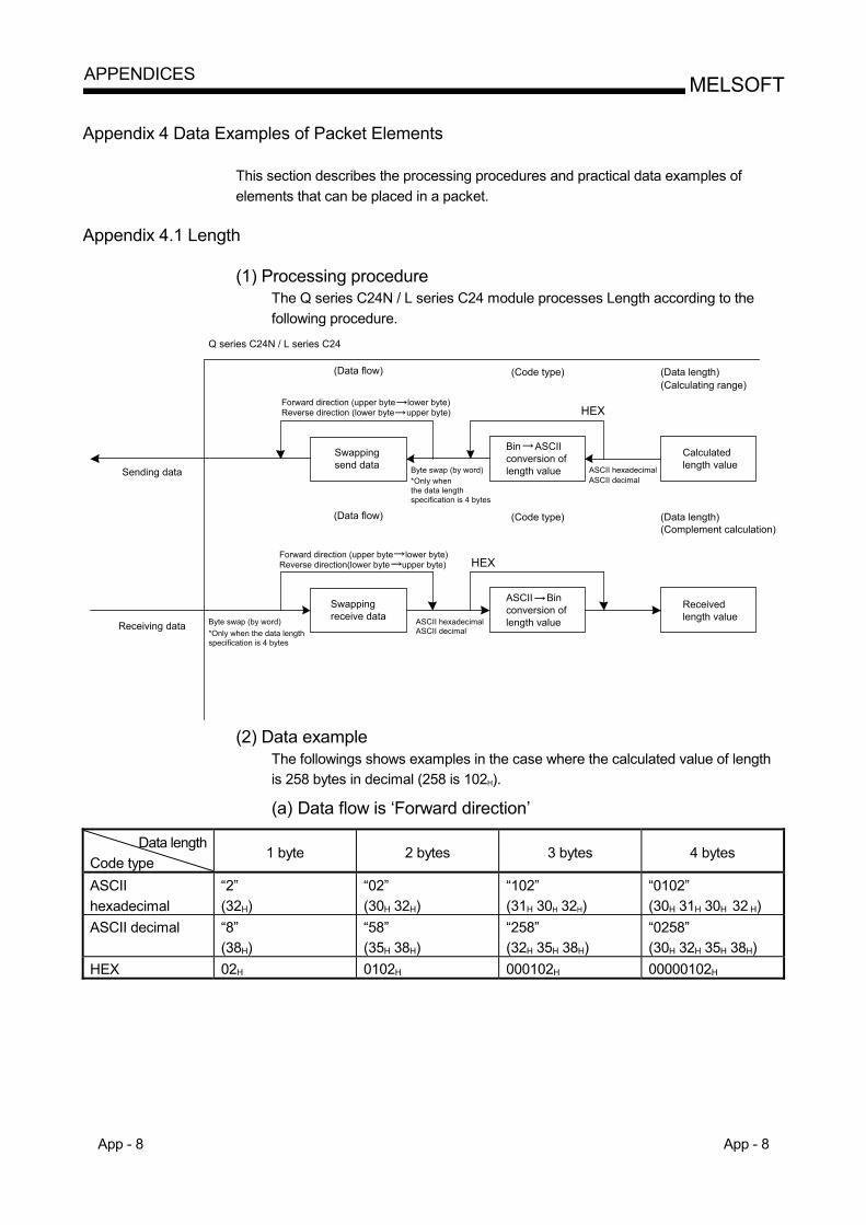
App - 8 App - 8
MELSOFTAPPENDICES
Appendix 4 Data Examples of Packet Elements
This section describes the processing procedures and practical data examples of elements that can be placed in a packet.
Appendix 4.1 Length
(1) Processing procedure The Q series C24N / L series C24 module processes Length according to the following procedure.
Receivedlength value
(Data flow)
(Data flow)
Sending data
Receiving data
Swappingsend data
Bin ASCIIconversion oflength value
Calculatedlength value
Swappingreceive data
ASCII Binconversion oflength value
Byte swap (by word)*Only whenthe data lengthspecification is 4 bytes
Byte swap (by word)*Only when the data lengthspecification is 4 bytes
ASCII hexadecimalASCII decimal
ASCII hexadecimalASCII decimal
Forward direction (upper byte lower byte)Reverse direction (lower byte upper byte)
Forward direction (upper byte lower byte)Reverse direction(lower byte upper byte)
Q series C24N / L series C24
(Code type) (Data length)(Calculating range)
(Code type) (Data length)(Complement calculation)
HEX
HEX
(2) Data example
The followings shows examples in the case where the calculated value of length is 258 bytes in decimal (258 is 102H).
(a) Data flow is ‘Forward direction’
Data length
Code type 1 byte 2 bytes 3 bytes 4 bytes
ASCII hexadecimal
“2” (32H)
“02” (30H 32H)
“102” (31H 30H 32H)
“0102” (30H 31H 30H 32 H)
ASCII decimal “8” (38H)
“58” (35H 38H)
“258” (32H 35H 38H)
“0258” (30H 32H 35H 38H)
HEX 02H 0102H 000102H 00000102H
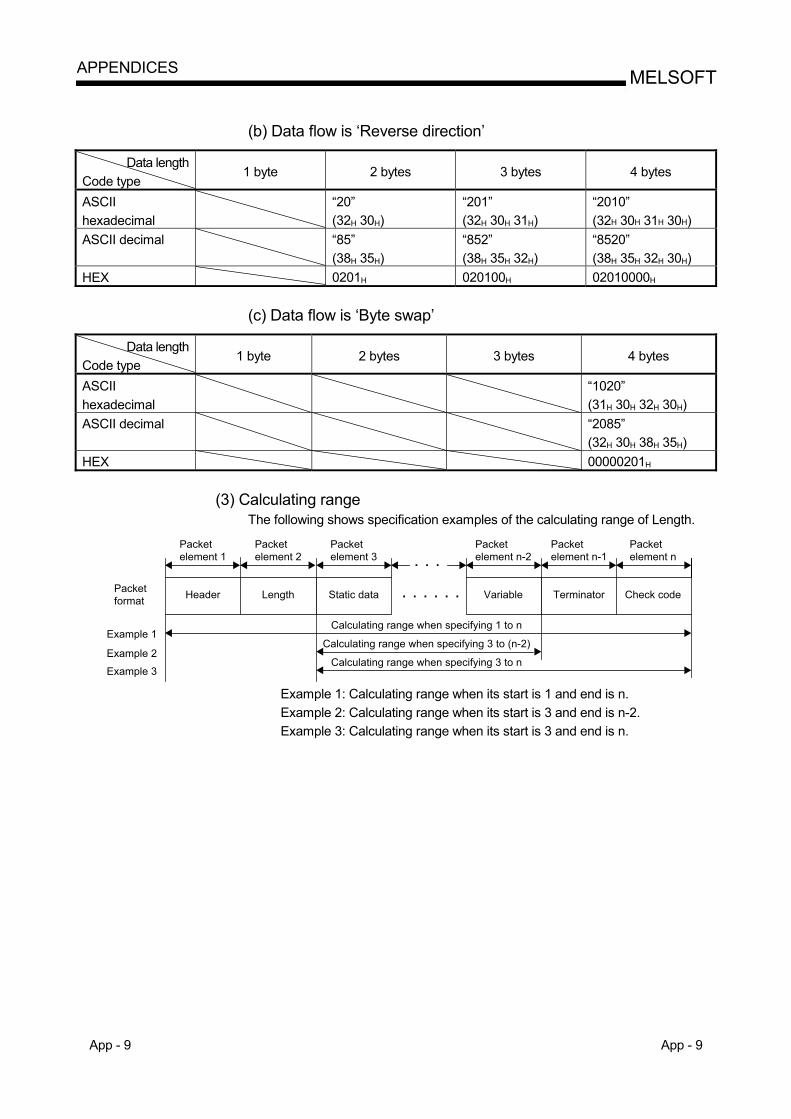
App - 9 App - 9
MELSOFTAPPENDICES
(b) Data flow is ‘Reverse direction’
Data length
Code type 1 byte 2 bytes 3 bytes 4 bytes
ASCII hexadecimal
“20” (32H 30H)
“201” (32H 30H 31H)
“2010” (32H 30H 31H 30H)
ASCII decimal “85” (38H 35H)
“852” (38H 35H 32H)
“8520” (38H 35H 32H 30H)
HEX 0201H 020100H 02010000H
(c) Data flow is ‘Byte swap’
Data length Code type
1 byte 2 bytes 3 bytes 4 bytes
ASCII hexadecimal
“1020” (31H 30H 32H 30H)
ASCII decimal “2085” (32H 30H 38H 35H)
HEX 00000201H
(3) Calculating range The following shows specification examples of the calculating range of Length.
TerminatorHeader Variable Check codeStatic data
Packetelement 1
Packetelement 3
Packetelement n
Packetelement n-1
Packetelement n-2
Packetformat
Calculating range when specifying 1 to n
Calculating range when specifying 3 to (n-2)
Calculating range when specifying 3 to n
Example 1
Example 2
Example 3
Length
Packetelement 2
Example 1: Calculating range when its start is 1 and end is n. Example 2: Calculating range when its start is 3 and end is n-2. Example 3: Calculating range when its start is 3 and end is n.
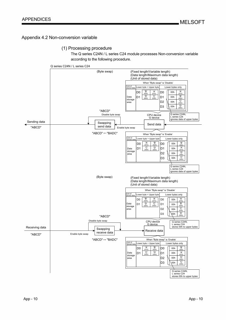
App - 10 App - 10
MELSOFTAPPENDICES
Appendix 4.2 Non-conversion variable
(1) Processing procedure The Q series C24N / L series C24 module processes Non-conversion variable according to the following procedure.
00hD0D1D2D3
D0D1 00h
00h
00h
Unit ofstored data
00hD0D1D2D3
D0D1 00h
00h
00h
Unit ofstored data
00hD0D1D2D3
D0D1 00h
00h
00h
Unit ofstored data
00hD0
D1
D2
D3
D0
D1 00h
00h
00h
Unit ofstored data
Sending data
"ABCD"
"ABCD"
Enable byte swap
Disable byte swap"ABCD"
(Byte swap) (Fixed length/Variable length)(Data length/Maximum data length)(Unit of stored data)
When "Byte swap" is ’Disable’
Lower byte + Upper byte Lower bytes only
Swappingsend data
(Byte swap)
Disable byte swap
Enable byte swap
Swappingreceive data
Receiving data
"ABCD"
Datastoragearea
Datastoragearea
Datastoragearea
’B’(42h)
’A’(41h)
’D’(44h)
’C’(43h)
CPU deviceG device
’A’(41h)
’B’(42h)’C’
(43h)
’D’(44h)
When "Byte swap" is ’Enable’
Lower byte + Upper byte Lower bytes only
’A’(41h)
’B’(42h)
’C’(43h)
’D’(44h)
’B’(42h)’A’
(41h)
’D’(44h)
’C’(43h)
When "Byte swap" is ’Disable’
Lower byte + Upper byte Lower bytes only
’B’(42h)
’D’(44h)
’A’(41h)’C’
(43h)
’A’(41h)’B’
(42h)
’C’(43h)
’D’(44h)
CPU deviceG device
When "Byte swap" is ’Enable’Lower byte + Upper byte Lower bytes only
’A’(41h)
’B’(42h)
’C’(43h)
’D’(44h)
Send data
Receive data
’B’(42h)
’A’(41h)
’D’(44h)’C’
(43h)
Q series C24N, L series C24ignores data of upper bytes
Q series C24N, L series C24ignores data of upper bytes
Q series C24N, L series C24stores 00h to upper bytes
Q series C24N, L series C24stores 00h to upper bytes
Q series C24N / L series C24
Datastoragearea
(Fixed length/Variable length)(Data length/Maximum data length)(Unit of stored data)
"ABCD" "BADC"
"ABCD" "BADC"
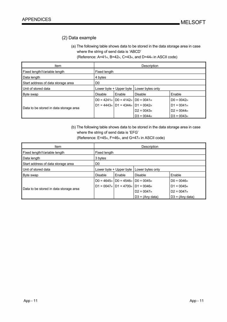
App - 11 App - 11
MELSOFTAPPENDICES
(2) Data example
(a) The following table shows data to be stored in the data storage area in case
where the string of send data is ‘ABCD’ (Reference: A=41H, B=42H, C=43H, and D=44H in ASCII code)
Item Description
Fixed length/Variable length Fixed length Data length 4 bytes Start address of data storage area D0 Unit of stored data Lower byte + Upper byte Lower bytes only Byte swap Disable Enable Disable Enable
Data to be stored in data storage area
D0 = 4241H
D1 = 4443H
D0 = 4142H
D1 = 4344H
D0 = 0041H D1 = 0042H D2 = 0043H D3 = 0044H
D0 = 0042H D1 = 0041H D2 = 0044H D3 = 0043H
(b) The following table shows data to be stored in the data storage area in case
where the string of send data is ‘EFG’ (Reference: E=45H, F=46H, and G=47H in ASCII code)
Item Description
Fixed length/Variable length Fixed length Data length 3 bytes Start address of data storage area D0 Unit of stored data Lower byte + Upper byte Lower bytes only Byte swap Disable Enable Disable Enable
Data to be stored in data storage area
D0 = 4645H
D1 = 0047H
D0 = 4546H
D1 = 4700H
D0 = 0045H D1 = 0046H D2 = 0047H D3 = (Any data)
D0 = 0046H D1 = 0045H D2 = 0047H D3 = (Any data)
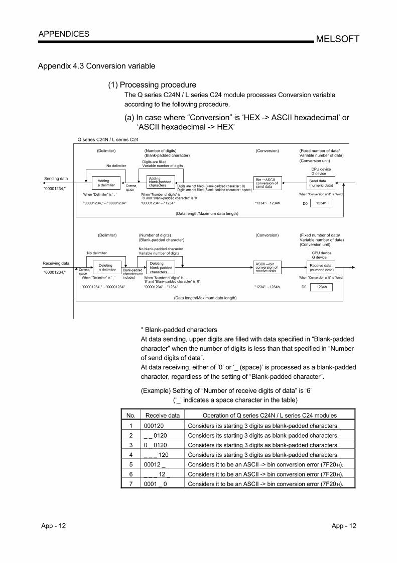
App - 12 App - 12
MELSOFTAPPENDICES
Appendix 4.3 Conversion variable
(1) Processing procedure The Q series C24N / L series C24 module processes Conversion variable according to the following procedure.
(a) In case where “Conversion” is ‘HEX -> ASCII hexadecimal’ or
‘ASCII hexadecimal -> HEX’
Digits are filledVariable number of digits
1234h
Sending data
Receiving data
"00001234,"
"00001234,"
Q series C24N / L series C24
(Delimiter) (Number of digits)(Blank-padded character)
(Conversion) (Fixed number of data/Variable number of data)(Conversion unit)
Addinga delimiter
When "Delimiter" is ’ , ’ When "Number of digits" is ’8’ and "Blank-padded character" is ’0’
Digits are not filled (Blank-padded character : 0)Digits are not filled (Blank-padded character : space)
(Data length/Maximum data length)
Send data(numeric data)
CPU deviceG device
D0
When "Conversion unit" is ’Word’
1234h
(Fixed number of data/Variable number of data)(Conversion unit)
(Conversion)(Delimiter) (Number of digits)(Blank-padded character)
No blank-padded characterVariable number of digitsNo delimiter
Comma,space
Comma,space
When "Delimiter" is ’ , ’
Blank-paddedcharacters areincluded When "Number of digits" is
’8’ and "Blank-padded character" is ’0’
Deletingblank-paddedcharacters
Deletinga delimiter
(Data length/Maximum data length)
D0
When "Conversion unit" is ’Word’
CPU deviceG device
Receive data(numeric data)
Addingblank-paddedcharacters
No delimiter
"00001234," "00001234" "00001234" "1234"
"00001234," "00001234" "00001234" "1234"
"1234" 1234h
"1234" 1234h
Bin ASCIIconversion ofsend data
ASCII binconversion ofreceive data
* Blank-padded characters At data sending, upper digits are filled with data specified in “Blank-padded character” when the number of digits is less than that specified in “Number of send digits of data”. At data receiving, either of ‘0’ or ‘_ (space)’ is processed as a blank-padded character, regardless of the setting of “Blank-padded character”.
(Example) Setting of “Number of receive digits of data” is ‘6’
(‘_’ indicates a space character in the table)
No. Receive data Operation of Q series C24N / L series C24 modules
1 000120 Considers its starting 3 digits as blank-padded characters. 2 _ _ 0120 Considers its starting 3 digits as blank-padded characters. 3 0 _ 0120 Considers its starting 3 digits as blank-padded characters. 4 _ _ _ 120 Considers its starting 3 digits as blank-padded characters. 5 00012 _ Considers it to be an ASCII -> bin conversion error (7F20 H). 6 _ _ _ 12 _ Considers it to be an ASCII -> bin conversion error (7F20 H). 7 0001 _ 0 Considers it to be an ASCII -> bin conversion error (7F20 H).
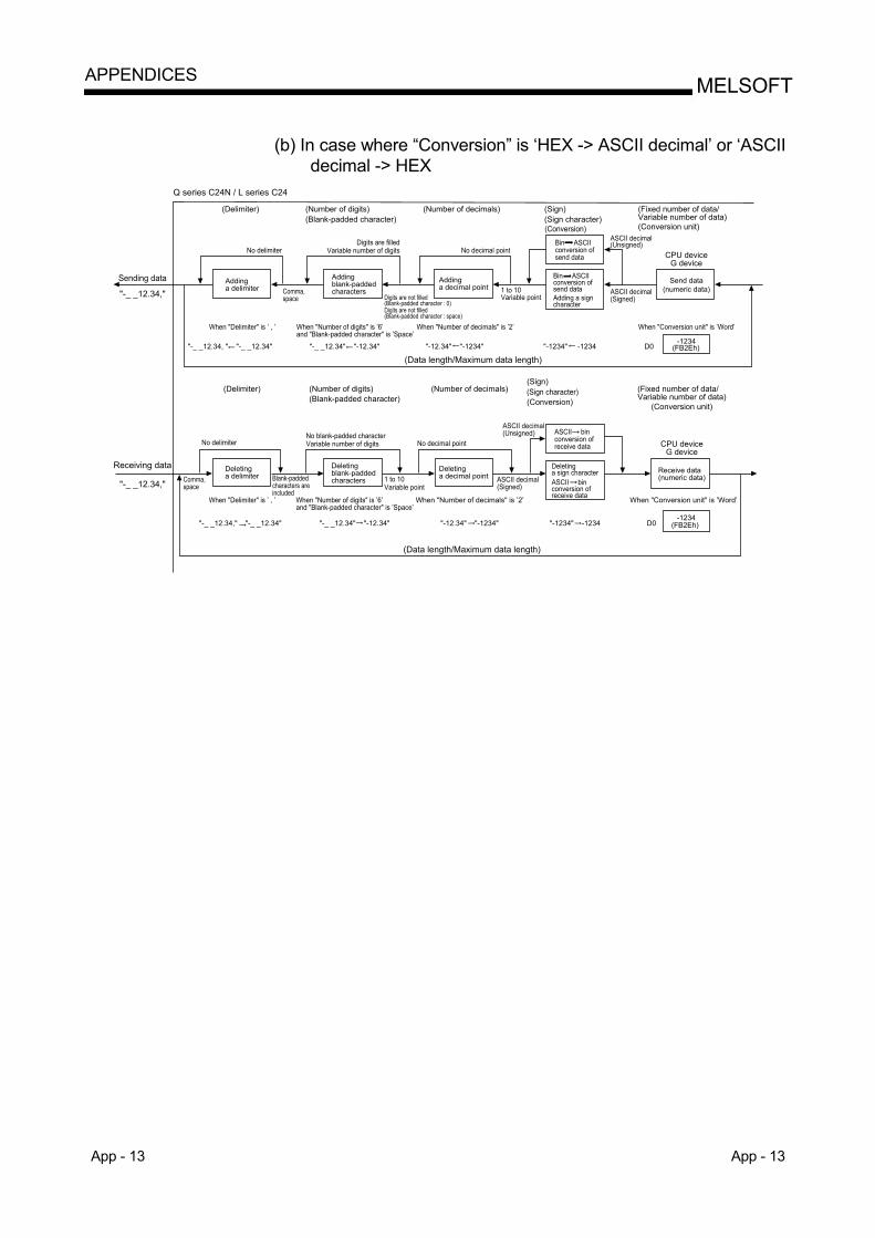
App - 13 App - 13
MELSOFTAPPENDICES
(b) In case where “Conversion” is ‘HEX -> ASCII decimal’ or ‘ASCII
decimal -> HEX
(Delimiter)
Sending data
"-_ _12.34,"
No delimiterDigits are filled
Variable number of digits No decimal pointASCII decimal(Unsigned)
CPU deviceG device
(Number of digits)(Blank-padded character)
(Number of decimals) (Sign)(Sign character)
(Fixed number of data/Variable number of data)(Conversion unit)
Q series C24N / L series C24
Addinga delimiter
When "Delimiter" is ’ , ’
"-_ _12.34, " "-_ _12.34"
Addingblank-paddedcharactersComma,
space
Bin ASCIIconversion ofsend data
Bin ASCIIconversion ofsend dataAdding a signcharacter
Send data(numeric data)
When "Number of digits" is ’6’and "Blank-padded character" is ’Space’
"-_ _12.34" "-12.34"
Digits are not filled(Blank-padded character : 0)
When "Number of decimals" is ’2’
"-12.34" "-1234" "-1234" -1234
ASCII decimal(Signed)
1 to 10Variable point
When "Conversion unit" is ’Word’
D0-1234
(FB2Eh)
Receiving data
"-_ _12.34,"
No delimiterNo blank-padded characterVariable number of digits No decimal point
When "Delimiter" is ’ , ’
Comma,space
Deletinga delimiter Blank-padded
characters areincluded
Deletingblank-paddedcharacters
Deletinga decimal point
Addinga decimal point
"-_ _12.34," "-_ _12.34" "-_ _12.34" "-12.34"
When "Number of decimals" is ’2’
1 to 10Variable point
"-12.34" "-1234"
ASCII decimal(Unsigned)
ASCII decimal(Signed)
ASCII binconversion ofreceive data
Deletinga sign characterASCII binconversion ofreceive data
CPU deviceG device
Receive data(numeric data)
When "Conversion unit" is ’Word’
D0-1234
(FB2Eh)"-1234" -1234
(Data length/Maximum data length)
(Data length/Maximum data length)
(Delimiter) (Number of digits) (Blank-padded character)
(Number of decimals)(Sign)
(Conversion)(Fixed number of data/Variable number of data)
(Conversion unit)
When "Number of digits" is ’6’and "Blank-padded character" is ’Space’
Digits are not filled(Blank-padded character : space)
(Sign character)
(Conversion)
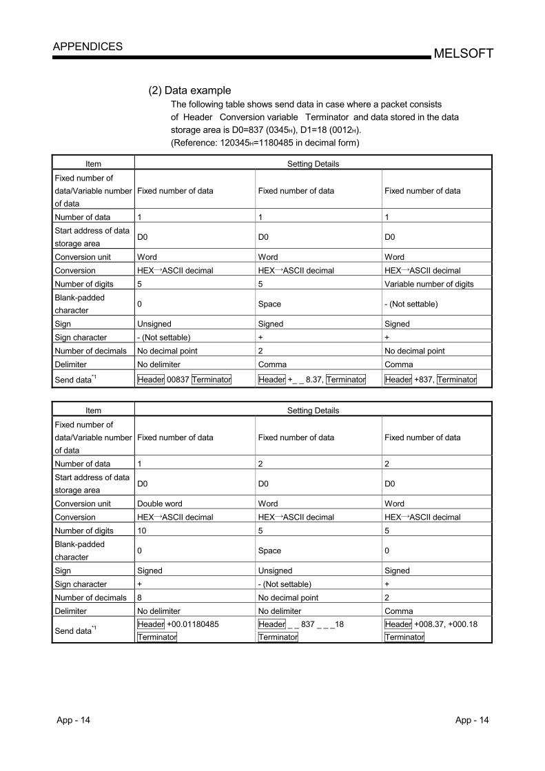
App - 14 App - 14
MELSOFTAPPENDICES
(2) Data example
The following table shows send data in case where a packet consists of Header Conversion variable Terminator and data stored in the data storage area is D0=837 (0345H), D1=18 (0012H). (Reference: 120345H=1180485 in decimal form)
Item Setting Details
Fixed number of data/Variable number of data
Fixed number of data Fixed number of data Fixed number of data
Number of data 1 1 1 Start address of data storage area
D0 D0 D0
Conversion unit Word Word Word Conversion HEX ASCII decimal HEX ASCII decimal HEX ASCII decimal Number of digits 5 5 Variable number of digits Blank-padded character
0 Space - (Not settable)
Sign Unsigned Signed Signed Sign character - (Not settable) + + Number of decimals No decimal point 2 No decimal point Delimiter No delimiter Comma Comma
Send data*1 Header 00837 Terminator Header +_ _ 8.37, Terminator Header +837, Terminator
Item Setting Details
Fixed number of data/Variable number of data
Fixed number of data Fixed number of data Fixed number of data
Number of data 1 2 2 Start address of data storage area
D0 D0 D0
Conversion unit Double word Word Word Conversion HEX ASCII decimal HEX ASCII decimal HEX ASCII decimal Number of digits 10 5 5 Blank-padded character
0 Space 0
Sign Signed Unsigned Signed Sign character + - (Not settable) + Number of decimals 8 No decimal point 2 Delimiter No delimiter No delimiter Comma
Send data*1 Header +00.01180485 Terminator
Header _ _ 837 _ _ _18 Terminator
Header +008.37, +000.18 Terminator
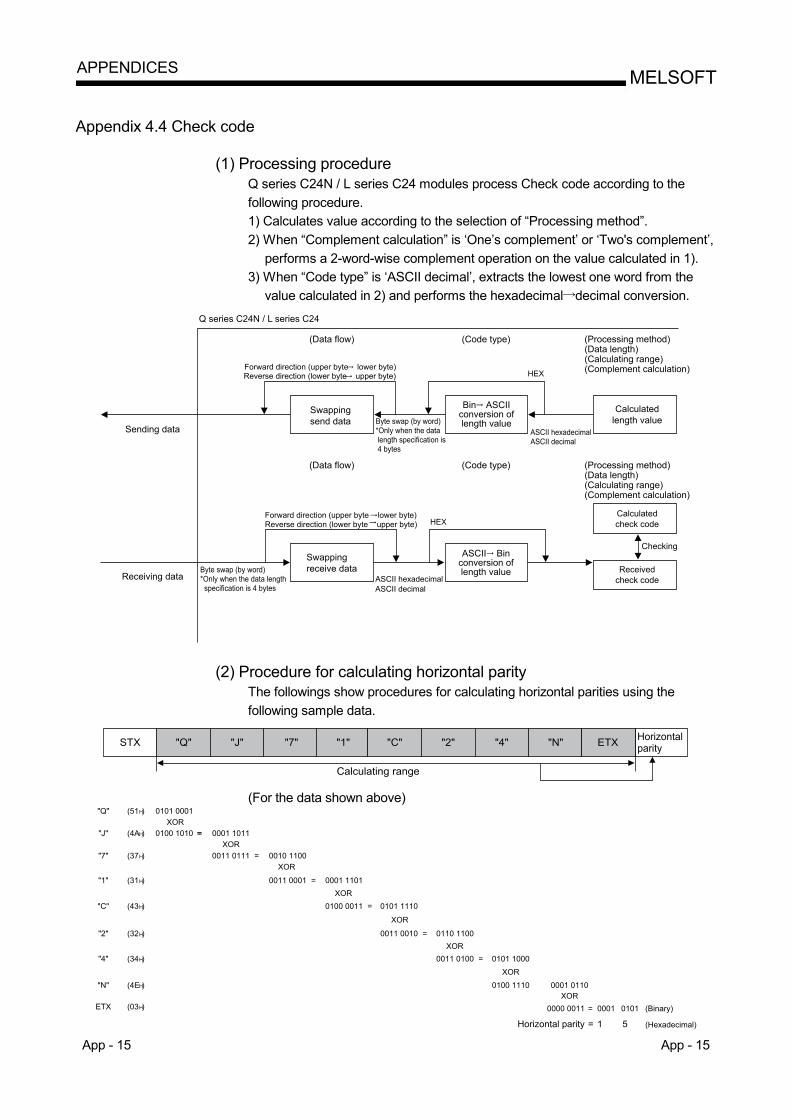
App - 15 App - 15
MELSOFTAPPENDICES
Appendix 4.4 Check code
(1) Processing procedure Q series C24N / L series C24 modules process Check code according to the following procedure. 1) Calculates value according to the selection of “Processing method”. 2) When “Complement calculation” is ‘One’s complement’ or ‘Two's complement’,
performs a 2-word-wise complement operation on the value calculated in 1). 3) When “Code type” is ‘ASCII decimal’, extracts the lowest one word from the
value calculated in 2) and performs the hexadecimal decimal conversion.
(Data flow)
(Data flow)
Sending data
Receiving data
Swappingsend data
Bin ASCIIconversion oflength value
Calculatedlength value
Swappingreceive data
ASCII Binconversion oflength value
Calculatedcheck code
Receivedcheck code
Byte swap (by word)*Only when the data length specification is 4 bytes
Byte swap (by word)*Only when the data length specification is 4 bytes
ASCII hexadecimal
ASCII hexadecimal
Forward direction (upper byte lower byte)
Forward direction (upper byte lower byte)Reverse direction (lower byte upper byte) HEX
Q series C24N / L series C24
(Code type) (Processing method)(Data length)(Calculating range)(Complement calculation)
(Code type) (Processing method)(Data length)(Calculating range)(Complement calculation)
Checking
Reverse direction (lower byte upper byte)
ASCII decimal
HEX
ASCII decimal
(2) Procedure for calculating horizontal parity The followings show procedures for calculating horizontal parities using the following sample data.
STX "J" "7" "1" "C" "2" "4" "N" ETX Horizontal
parity
Calculating range
"Q"
(For the data shown above)
"Q" (51H) 0101 0001XOR
"J" (4AH) 0100 1010 == 0001 1011XOR
"7" (37H) 0011 0111 = 0010 1100XOR
"1" (31H) 0011 0001 = 0001 1101XOR
"C" (43H) 0100 0011 = 0101 1110
XOR
"2" (32H) 0011 0010 = 0110 1100XOR
"4" (34H) 0011 0100 = 0101 1000
XOR
"N" (4EH) 0100 1110 0001 0110XOR
ETX (03H) 0000 0011 = 0101 (Binary)
(Hexadecimal)Horizontal parity 5
0001
1=
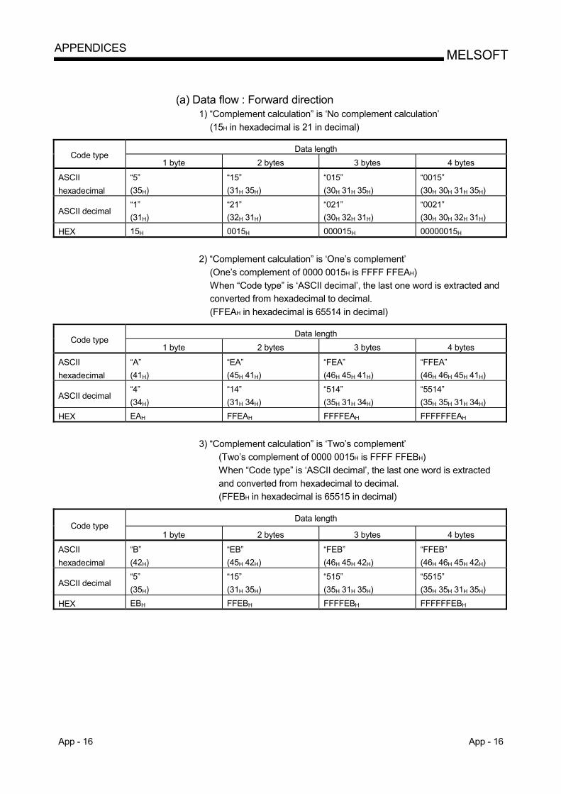
App - 16 App - 16
MELSOFTAPPENDICES
(a) Data flow : Forward direction
1) “Complement calculation” is ‘No complement calculation’ (15H in hexadecimal is 21 in decimal)
Data length
Code type 1 byte 2 bytes 3 bytes 4 bytes
ASCII hexadecimal
“5” (35H)
“15” (31H 35H)
“015” (30H 31H 35H)
“0015” (30H 30H 31H 35H)
ASCII decimal “1” (31H)
“21” (32H 31H)
“021” (30H 32H 31H)
“0021” (30H 30H 32H 31H)
HEX 15H 0015H 000015H 00000015H
2) “Complement calculation” is ‘One’s complement’
(One’s complement of 0000 0015H is FFFF FFEAH) When “Code type” is ‘ASCII decimal’, the last one word is extracted and converted from hexadecimal to decimal. (FFEAH in hexadecimal is 65514 in decimal)
Data length
Code type 1 byte 2 bytes 3 bytes 4 bytes
ASCII hexadecimal
“A” (41H)
“EA” (45H 41H)
“FEA” (46H 45H 41H)
“FFEA” (46H 46H 45H 41H)
ASCII decimal “4” (34H)
“14” (31H 34H)
“514” (35H 31H 34H)
“5514” (35H 35H 31H 34H)
HEX EAH FFEAH FFFFEAH FFFFFFEAH
3) “Complement calculation” is ‘Two’s complement’
(Two’s complement of 0000 0015H is FFFF FFEBH) When “Code type” is ‘ASCII decimal’, the last one word is extracted and converted from hexadecimal to decimal. (FFEBH in hexadecimal is 65515 in decimal)
Data length
Code type 1 byte 2 bytes 3 bytes 4 bytes
ASCII hexadecimal
“B” (42H)
“EB” (45H 42H)
“FEB” (46H 45H 42H)
“FFEB” (46H 46H 45H 42H)
ASCII decimal “5” (35H)
“15” (31H 35H)
“515” (35H 31H 35H)
“5515” (35H 35H 31H 35H)
HEX EBH FFEBH FFFFEBH FFFFFFEBH
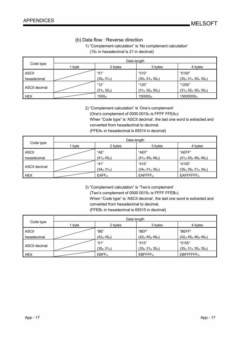
App - 17 App - 17
MELSOFTAPPENDICES
(b) Data flow : Reverse direction
1) “Complement calculation” is ‘No complement calculation’ (15H in hexadecimal is 21 in decimal)
Data length
Code type 1 byte 2 bytes 3 bytes 4 bytes
ASCII hexadecimal
“51” (35H 31H)
“510” (35H 31H 30H)
“5100” (35H 31H 30H 30H)
ASCII decimal “12”
(31H 32H) “120” (31H 32H 30H)
“1200” (31H 32H 30H 30H)
HEX 1500H 150000H 15000000H
2) “Complement calculation” is ‘One’s complement’
(One’s complement of 0000 0015H is FFFF FFEAH) When “Code type” is ‘ASCII decimal’, the last one word is extracted and converted from hexadecimal to decimal. (FFEAH in hexadecimal is 65514 in decimal)
Data length
Code type 1 byte 2 bytes 3 bytes 4 bytes
ASCII hexadecimal
“AE” (41H 45H)
“AEF” (41H 45H 46H)
“AEFF” (41H 45H 46H 46H)
ASCII decimal “41”
(34H 31H) “415” (34H 31H 35H)
“4155” (35H 35H 31H 34H)
HEX EAFFH EAFFFFH EAFFFFFFH
3) “Complement calculation” is ‘Two’s complement’
(Two’s complement of 0000 0015H is FFFF FFEBH) When “Code type” is ‘ASCII decimal’, the last one word is extracted and converted from hexadecimal to decimal. (FFEBH in hexadecimal is 65515 in decimal)
Data length
Code type 1 byte 2 bytes 3 bytes 4 bytes
ASCII hexadecimal
“BE” (42H 45H)
“BEF” (42H 45H 46H)
“BEFF” (42H 45H 46H 46H)
ASCII decimal “51”
(35H 31H) “515” (35H 31H 35H)
“5155” (35H 31H 35H 35H)
HEX EBFFH EBFFFFH EBFFFFFFH
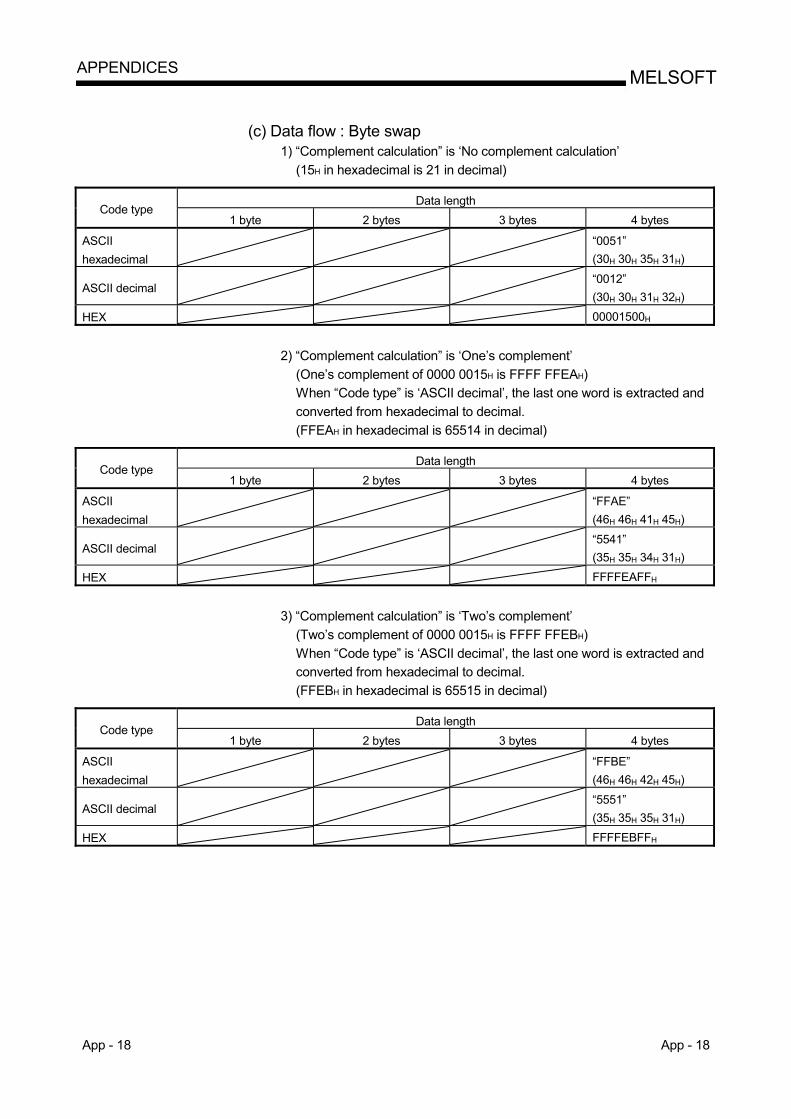
App - 18 App - 18
MELSOFTAPPENDICES
(c) Data flow : Byte swap
1) “Complement calculation” is ‘No complement calculation’ (15H in hexadecimal is 21 in decimal)
Data length
Code type 1 byte 2 bytes 3 bytes 4 bytes
ASCII hexadecimal
“0051” (30H 30H 35H 31H)
ASCII decimal “0012”
(30H 30H 31H 32H)
HEX 00001500H
2) “Complement calculation” is ‘One’s complement’
(One’s complement of 0000 0015H is FFFF FFEAH) When “Code type” is ‘ASCII decimal’, the last one word is extracted and converted from hexadecimal to decimal. (FFEAH in hexadecimal is 65514 in decimal)
Data length
Code type 1 byte 2 bytes 3 bytes 4 bytes
ASCII hexadecimal
“FFAE” (46H 46H 41H 45H)
ASCII decimal “5541”
(35H 35H 34H 31H)
HEX FFFFEAFFH
3) “Complement calculation” is ‘Two’s complement’
(Two’s complement of 0000 0015H is FFFF FFEBH) When “Code type” is ‘ASCII decimal’, the last one word is extracted and converted from hexadecimal to decimal. (FFEBH in hexadecimal is 65515 in decimal)
Data length
Code type 1 byte 2 bytes 3 bytes 4 bytes
ASCII hexadecimal
“FFBE” (46H 46H 42H 45H)
ASCII decimal “5551”
(35H 35H 35H 31H)
HEX FFFFEBFFH
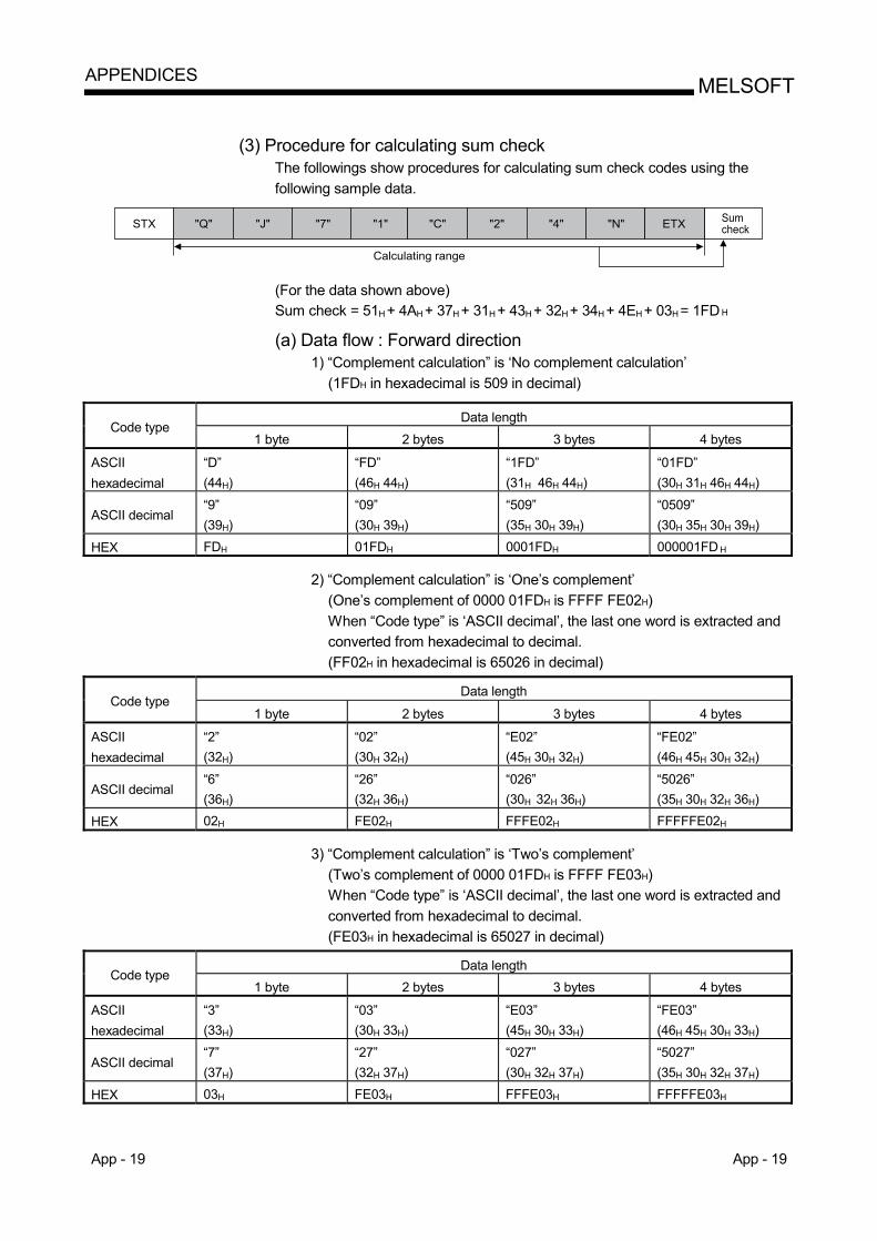
App - 19 App - 19
MELSOFTAPPENDICES
(3) Procedure for calculating sum check
The followings show procedures for calculating sum check codes using the following sample data.
STX "J" "7" "1" "C" "2" "4" "N" ETX
Calculating range
"Q" Sumcheck
(For the data shown above) Sum check = 51H + 4AH + 37H + 31H + 43H + 32H + 34H + 4EH + 03H = 1FD H
(a) Data flow : Forward direction
1) “Complement calculation” is ‘No complement calculation’ (1FDH in hexadecimal is 509 in decimal)
Data length
Code type 1 byte 2 bytes 3 bytes 4 bytes
ASCII hexadecimal
“D” (44H)
“FD” (46H 44H)
“1FD” (31H 46H 44H)
“01FD” (30H 31H 46H 44H)
ASCII decimal “9” (39H)
“09” (30H 39H)
“509” (35H 30H 39H)
“0509” (30H 35H 30H 39H)
HEX FDH 01FDH 0001FDH 000001FD H
2) “Complement calculation” is ‘One’s complement’ (One’s complement of 0000 01FDH is FFFF FE02H) When “Code type” is ‘ASCII decimal’, the last one word is extracted and converted from hexadecimal to decimal. (FF02H in hexadecimal is 65026 in decimal)
Data length Code type
1 byte 2 bytes 3 bytes 4 bytes
ASCII hexadecimal
“2” (32H)
“02” (30H 32H)
“E02” (45H 30H 32H)
“FE02” (46H 45H 30H 32H)
ASCII decimal “6” (36H)
“26” (32H 36H)
“026” (30H 32H 36H)
“5026” (35H 30H 32H 36H)
HEX 02H FE02H FFFE02H FFFFFE02H
3) “Complement calculation” is ‘Two’s complement’ (Two’s complement of 0000 01FDH is FFFF FE03H) When “Code type” is ‘ASCII decimal’, the last one word is extracted and converted from hexadecimal to decimal. (FE03H in hexadecimal is 65027 in decimal)
Data length Code type
1 byte 2 bytes 3 bytes 4 bytes
ASCII hexadecimal
“3” (33H)
“03” (30H 33H)
“E03” (45H 30H 33H)
“FE03” (46H 45H 30H 33H)
ASCII decimal “7” (37H)
“27” (32H 37H)
“027” (30H 32H 37H)
“5027” (35H 30H 32H 37H)
HEX 03H FE03H FFFE03H FFFFFE03H
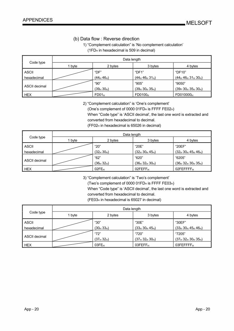
App - 20 App - 20
MELSOFTAPPENDICES
(b) Data flow : Reverse direction
1) “Complement calculation” is ‘No complement calculation’ (1FDH in hexadecimal is 509 in decimal)
Data length
Code type 1 byte 2 bytes 3 bytes 4 bytes
ASCII hexadecimal
“DF” (44H 46H)
“DF1” (44H 46H 31H)
“DF10” (44H 46H 31H 30H)
ASCII decimal “90”
(39H 30H) “905” (39H 30H 35H)
“9050” (39H 30H 35H 30H)
HEX FD01H FD0100H FD010000H
2) “Complement calculation” is ‘One’s complement’ (One’s complement of 0000 01FDH is FFFF FE02H) When “Code type” is ‘ASCII decimal’, the last one word is extracted and converted from hexadecimal to decimal. (FF02H in hexadecimal is 65026 in decimal)
Data length
Code type 1 byte 2 bytes 3 bytes 4 bytes
ASCII hexadecimal
“20” (32H 30H)
“20E” (32H 30H 45H)
“20EF” (32H 30H 45H 46H)
ASCII decimal “62”
(36H 32H) “620” (36H 32H 30H)
“6205” (36H 32H 30H 35H)
HEX 02FEH 02FEFFH 02FEFFFFH
3) “Complement calculation” is ‘Two’s complement’ (Two’s complement of 0000 01FDH is FFFF FE03H) When “Code type” is ‘ASCII decimal’, the last one word is extracted and converted from hexadecimal to decimal. (FE03H in hexadecimal is 65027 in decimal)
Data length
Code type 1 byte 2 bytes 3 bytes 4 bytes
ASCII hexadecimal
“30” (30H 33H)
“30E” (33H 30H 45H)
“30EF” (33H 30H 45H 46H)
ASCII decimal “72”
(37H 32H) “720” (37H 32H 30H)
“7205” (37H 32H 30H 35H)
HEX 03FEH 03FEFFH 03FEFFFFH
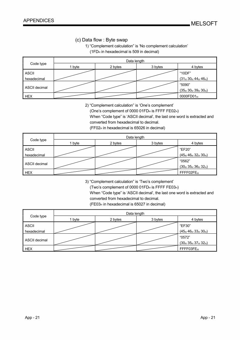
App - 21 App - 21
MELSOFTAPPENDICES
(c) Data flow : Byte swap
1) “Complement calculation” is ‘No complement calculation’ (1FDH in hexadecimal is 509 in decimal)
Data length
Code type 1 byte 2 bytes 3 bytes 4 bytes
ASCII hexadecimal
“10DF” (31H 30H 44H 46H)
ASCII decimal “5090”
(35H 30H 39H 30H)
HEX 0000FD01H
2) “Complement calculation” is ‘One’s complement’ (One’s complement of 0000 01FDH is FFFF FE02H) When “Code type” is ‘ASCII decimal’, the last one word is extracted and converted from hexadecimal to decimal. (FF02H in hexadecimal is 65026 in decimal)
Data length
Code type 1 byte 2 bytes 3 bytes 4 bytes
ASCII hexadecimal
“EF20” (45H 46H 32H 30H)
ASCII decimal “0562”
(30H 35H 36H 32H)
HEX FFFF02FEH
3) “Complement calculation” is ‘Two’s complement’ (Two’s complement of 0000 01FDH is FFFF FE03H) When “Code type” is ‘ASCII decimal’, the last one word is extracted and converted from hexadecimal to decimal. (FE03H in hexadecimal is 65027 in decimal)
Data length
Code type 1 byte 2 bytes 3 bytes 4 bytes
ASCII hexadecimal
“EF30” (45H 46H 33H 30H)
ASCII decimal “0572”
(30H 35H 37H 32H)
HEX FFFF03FEH
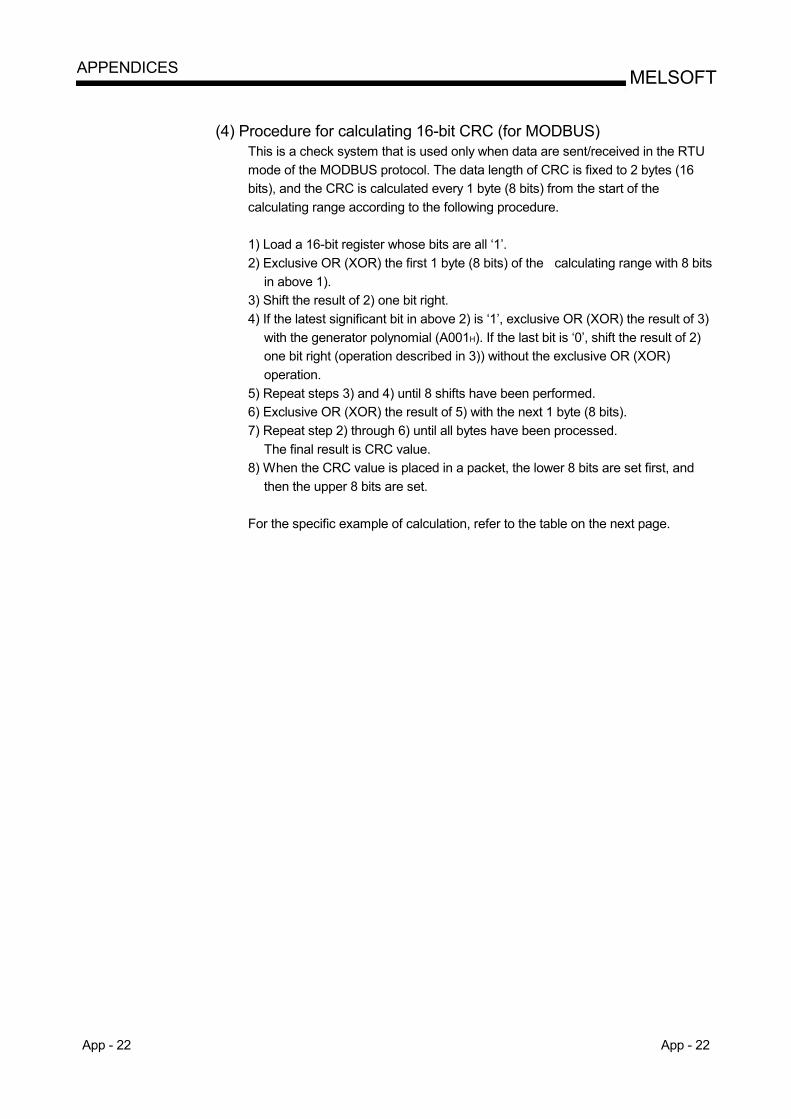
App - 22 App - 22
MELSOFTAPPENDICES
(4) Procedure for calculating 16-bit CRC (for MODBUS)
This is a check system that is used only when data are sent/received in the RTU mode of the MODBUS protocol. The data length of CRC is fixed to 2 bytes (16 bits), and the CRC is calculated every 1 byte (8 bits) from the start of the calculating range according to the following procedure. 1) Load a 16-bit register whose bits are all ‘1’. 2) Exclusive OR (XOR) the first 1 byte (8 bits) of the calculating range with 8 bits
in above 1). 3) Shift the result of 2) one bit right. 4) If the latest significant bit in above 2) is ‘1’, exclusive OR (XOR) the result of 3)
with the generator polynomial (A001H). If the last bit is ‘0’, shift the result of 2) one bit right (operation described in 3)) without the exclusive OR (XOR) operation.
5) Repeat steps 3) and 4) until 8 shifts have been performed. 6) Exclusive OR (XOR) the result of 5) with the next 1 byte (8 bits). 7) Repeat step 2) through 6) until all bytes have been processed.
The final result is CRC value. 8) When the CRC value is placed in a packet, the lower 8 bits are set first, and
then the upper 8 bits are set. For the specific example of calculation, refer to the table on the next page.
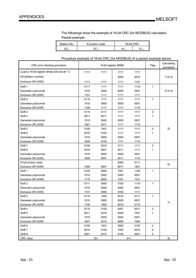
App - 23 App - 23
MELSOFTAPPENDICES
The followings show the example of 16-bit CRC (for MODBUS) calculation. Packet example:
Station No. Function code 16-bit CRC 02 H 07 H 41 H 12 H
Procedure example of 16-bit CRC (for MODBUS) of a packet example above:
CRC error checking procedure 16-bit register (MSB) Flag Calculating procedure
(Load a 16-bit register whose bits are all ‘1’) 1111 1111 1111 1111
02H(Station number) 0000 0010
Exclusive OR (XOR) 1111 1111 1111 1101
1) to 2)
Shift 1 0111 1111 1111 1110 1 Generator polynomial 1010 0000 0000 0001 Exclusive OR (XOR) 1101 1111 1111 1111
3) to 4)
Shift 2 0110 1111 1111 1111 1 Generator polynomial 1010 0000 0000 0001 Exclusive OR (XOR) 1100 1111 1111 1110 Shift 3 0110 0111 1111 1111 0 Shift 4 0011 0011 1111 1111 1 Generator polynomial 1010 0000 0000 0001 Exclusive OR (XOR) 1001 0011 1111 1110 Shift 5 0100 1001 1111 1111 0 Shift 6 0010 0100 1111 1111 1 Generator polynomial 1010 0000 0000 0001 Exclusive OR (XOR) 1000 0100 1111 1110 Shift 7 0100 0010 0111 1111 0 Shift 8 0010 0001 0011 1111 1 Generator polynomial 1010 0000 0000 0001 Exclusive OR (XOR) 1000 0001 0011 1110
5)
07H(Function code) 0000 0111 Exclusive OR (XOR) 1000 0001 0011 1001
6)
Shift 1 0100 0000 1001 1100 1 Generator polynomial 1010 0000 0000 0001 Exclusive OR (XOR) 1110 0000 1001 1101 Shift 2 0111 0000 0100 1110 1 Generator polynomial 1010 0000 0000 0001 Exclusive OR (XOR) 1101 0000 0100 1111 Shift 3 0110 1000 0010 0111 1 Generator polynomial 1010 0000 0000 0001 Exclusive OR (XOR) 1100 1000 0010 0110 Shift 4 0110 0100 0001 0011 0 Shift 5 0011 0010 0000 1001 1 Generator polynomial 1010 0000 0000 0001 Exclusive OR (XOR) 1001 0010 0000 1000 Shift 6 0100 1001 0000 0100 0 Shift 7 0010 0100 1000 0010 0 Shift 8 0001 0010 0100 0001 0
7)
CRC value 12H 41H 8)
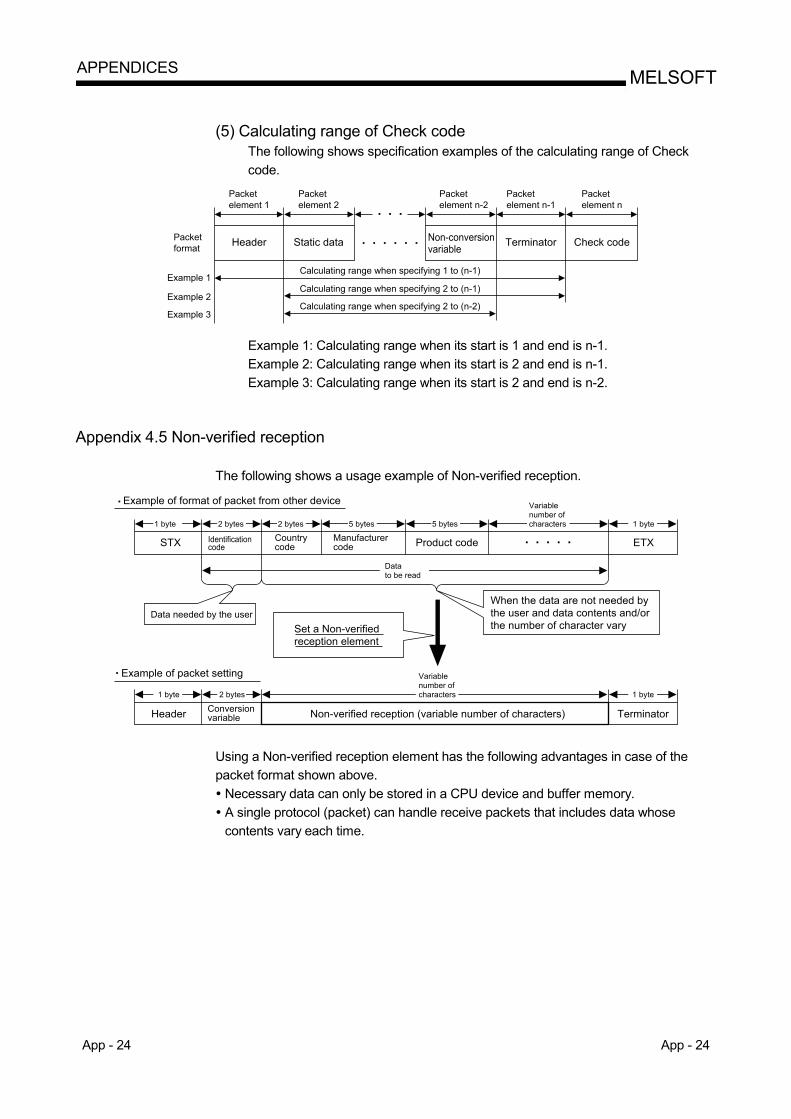
App - 24 App - 24
MELSOFTAPPENDICES
(5) Calculating range of Check code
The following shows specification examples of the calculating range of Check code.
Packetelement 1
Header Static data
Calculating range when specifying 1 to (n-1)Example 1
Packetformat
Example 2
Example 3
Calculating range when specifying 2 to (n-1)
Calculating range when specifying 2 to (n-2)
TerminatorNon-conversionvariable Check code
Packetelement 2
Packetelement n-2
Packetelement n-1
Packetelement n
Example 1: Calculating range when its start is 1 and end is n-1. Example 2: Calculating range when its start is 2 and end is n-1. Example 3: Calculating range when its start is 2 and end is n-2.
Appendix 4.5 Non-verified reception
The following shows a usage example of Non-verified reception.
1 byte
STX
Header Non-verified reception (variable number of characters) TerminatorConversionvariable
Data needed by the userSet a Non-verifiedreception element
When the data are not needed bythe user and data contents and/orthe number of character vary
Identificationcode
Countrycode
Manufacturercode Product code ETX
2 bytes
1 byte 2 bytes
2 bytes 5 bytes
Datato be read
5 bytes 1 byte
1 byte
Variablenumber ofcharacters
Variablenumber ofcharacters
Example of format of packet from other device
Example of packet setting
Using a Non-verified reception element has the following advantages in case of the packet format shown above. Necessary data can only be stored in a CPU device and buffer memory. A single protocol (packet) can handle receive packets that includes data whose contents vary each time.
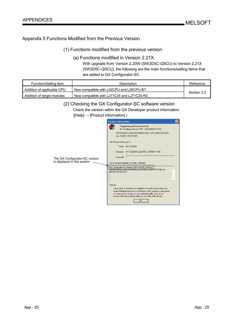
App - 25 App - 25
MELSOFTAPPENDICES
Appendix 5 Functions Modified from the Previous Version
(1) Functions modified from the previous version
(a) Functions modified in Version 2.21X With upgrade from Version 2.20W (SW2D5C-QSCU) to Version 2.21X (SW2D5C-QSCU), the following are the main functions/setting items that are added to GX Configurator-SC.
Function/Setting item Description Reference
Addition of applicable CPU Now compatible with L02CPU and L26CPU-BT.
Addition of target modules Now compatible with LJ71C24 and LJ71C24-R2. Section 3.2
(2) Checking the GX Configurator-SC software version
Check the version within the GX Developer product information. ([Help] [Product information] )
The GX Configurator-SC versionis displayed in this section.

App - 26 App - 26
MELSOFTAPPENDICES
MEMO
Index - 1 Index - 1
INDEX
[A]
Applicable CPU .............................................. 3- 2 Applicable module.......................................... 3- 2
[C] Circuit trace .................................................. 11- 6 Circuit trace option screen
Monitor buffer head address setting ....... 11-10 Monitor buffer size setting ....................... 11-10 Read......................................................... 11-10 Write......................................................... 11-10
Circuit trace screen Send/receive packets ............................... 11- 8 Communication control signals ................ 11- 8 Start........................................................... 11- 8
Communication type of protocol .................... 8- 4
[D] Data example of packet element ...............App- 8 Debugging support function......................... 11- 1 Dedicated instruction
G(P).CPRTCL.......................................... 13-18 Functional protocol .................................. 13-25
Device batch setting...................................... 9-35 Device list ...................................................... 9-29
[E] End.................................................................. 7- 1
[H] Help function...............................................App- 1
[I] I/O signal....................................................... 13- 1
[L] List of assignments of buffer memory ........ 13- 7
[M] Menu list ......................................................... 5- 2 Module verification ....................................... 10- 4
[O]
Opening circuit trace file ..............................11-11 Operating procedure
Procedure for setting through writing .........4- 1 Procedure for debugging ............................4- 2
[P]
Packet edit operation Deleting packet ..........................................8-12 Copying/pasting packet .............................8-13 Adding new element ..................................9-23 Changing element type..............................9-24
Packet element Header.........................................................9- 6 Static Data...................................................9- 6 Terminator ...................................................9- 7 Length..........................................................9- 8 Non-conversion variable ............................9-10 Conversion variable ...................................9-13 Check code ................................................9-20 Non-verified reception................................9-22
Packet element setting Header/Static Data/Terminator..................9-25 Length.........................................................9-27 Non-conversion variable ............................9-28 Conversion variable ...................................9-30 Check code ................................................9-33 Non-verified reception................................9-34
Pre-defined protocol ready (X1D) ................13- 2 Pre-defined protocol support function
Function list .................................................3- 1 Creating new file .........................................8- 1 Opening file .................................................8- 2 Closing file ...................................................8- 3 Saving file ....................................................8- 3 Adding protocol ...........................................8- 7 Changing to editable protocol.....................8- 7 Protocol detailed setting..............................8- 8 Setting send/receive parameter.................8-11 Deleting protocol ........................................8-12 Copying and pasting protocol ....................8-13
Print ...............................................................12- 1 Print example ................................................12- 2
ind
Index - 2 Index - 2
Programming example System configuration/wiring example ..... 13-27 Communication data ............................... 13-28 Communication setting............................ 13-29
Protocol........................................................... 1- 3 Protocol execution log display ....................... 1- 3
[R] Read from module........................................ 10- 3
[S] Saving circuit trace file ................................ 11-11 Screen display................................................ 5- 1 Selecting module for debugging
The present object module....................... 11- 2 Module list................................................. 11- 2 Channel specification ............................... 11- 2
Start ................................................................ 6- 1 State monitor ............................................... 11-12 State monitor <<Error information>> tab
Communication error status.................... 11-13 Switch setting, mode selection error....... 11-13 Communication result.............................. 11-13 Error reset ................................................ 11-13
State monitor <<Operation setting switch>> tab Switch setting status for the operation.... 11-14 Mode switch............................................. 11-14 Station switch........................................... 11-14
State monitor <<Pre-defined protocol function>> tab
Execution status ...................................... 11-15 Protocol cancel designation .................... 11-15 Pre-defined protocol function error code 11-15
State monitor <<Signal>> tab X signal state monitor.............................. 11-13 Y signal state monitor.............................. 11-13 RS-232 signal monitor............................. 11-13
Status bar ....................................................... 5- 3
[T] Tool button...................................................... 5- 3
[V] Verification operation of receive packet ....App- 7
[W] Write to module ............................................ 10- 1
ind

Microsoft, Windows, Windows NT, Windows Vista are registered trademarks of Microsoft Corporation in the United States and other countries. Pentium is a trademark of Intel Corporation in the United States and other countries. Ethernet is a trademark of Xerox Corporation. All other company names and product names used in this manual are trademarks or registered trademarks of their respective companies.
SH (NA)-080850ENG-C


SH(NA)-080850ENG-C(1009)MEEMODEL: GXCON-SC-O-PP-EMODEL CODE: 13JU66
Specifications subject to change without notice.
When exported from Japan, this manual does not require application to theMinistry of Economy, Trade and Industry for service transaction permission.
HEAD OFFICE : TOKYO BUILDING, 2-7-3 MARUNOUCHI, CHIYODA-KU, TOKYO 100-8310, JAPANNAGOYA WORKS : 1-14 , YADA-MINAMI 5-CHOME , HIGASHI-KU, NAGOYA , JAPAN