Embed Size (px)
Citation preview

Gutor SDC Rectifier/Battery Charger24 – 220 V; 25 – 1,200 AHigher ratings on request

*Data subject to change
Gutor SDC Technical dataRectifier Input
Voltage 3 x 380/400/415 V 3
Input voltage tolerance:DC in tolerancefor function(below -15% the battery might begin to discharge)
+/- 10%+15%/-25%
Frequency 50/60 Hz
Frequency tolerance +/- 8%
Power factor:at nominal line power and float voltageat -10% line power and float voltageat +10% line power and float voltage
~ 0.83~ 0.90~ 0.75
DC output
Voltage 24/48/110/125/220 VDC
Setting range:Float voltage at -10/+10% line power voltageFloat voltage at 0/+10% line power voltageBoost voltage at nominal line power voltageBattery operating range
100 – 120%100 – 130%100 – 130%150%
DC voltage tolerance +/- 1%
Dynamic behavior:10 –100% and 100 –10% load stepregulation time
maximum +/- 10% Vrms< 100 ms +/- 2%
DC ripple voltage
Standard with parallel battery capacity of 3x nominal current:Optional without batteryOptional without batteryOptional without battery (24/48 V)
≤ 2% rms≤ 1% rms≤ 2 mV (at 800 Hz, psophometric)
DC current according to type range
Setting range:Total output current limitationBattery current limitation
50 – 100%0 – 100%
DC current tolerance +/- 2%
Characteristic I-U according to DIN 41773
DC overcurrent capability 150% for 2s
General data
Ambient temperature range for storage from -20 to +70 °C
Ambient temperature range for operation from -10 to +40 °C
Altitude above sea level 1,000 m
Allowable air humidity <95% (non condensing)
Noise level standard n+1 fan system 55 – 65 dBA
Degree of protection IP20 according to IEC® 60529
Paint pearl light gray, RAL 9022 structure
Standards:SafetyEMCPerformance
IEC/EN 62040-1-2IEC 62040-2, EN 50091-2IEC/EN 62040-3, IEC 60146-1-1
Conformity CE-Label
Efficiency up to 94% depending on type
Cooling Natural convection up to 100 A/220 V and top forced-air ventilation with redundant n+1 monitored fans
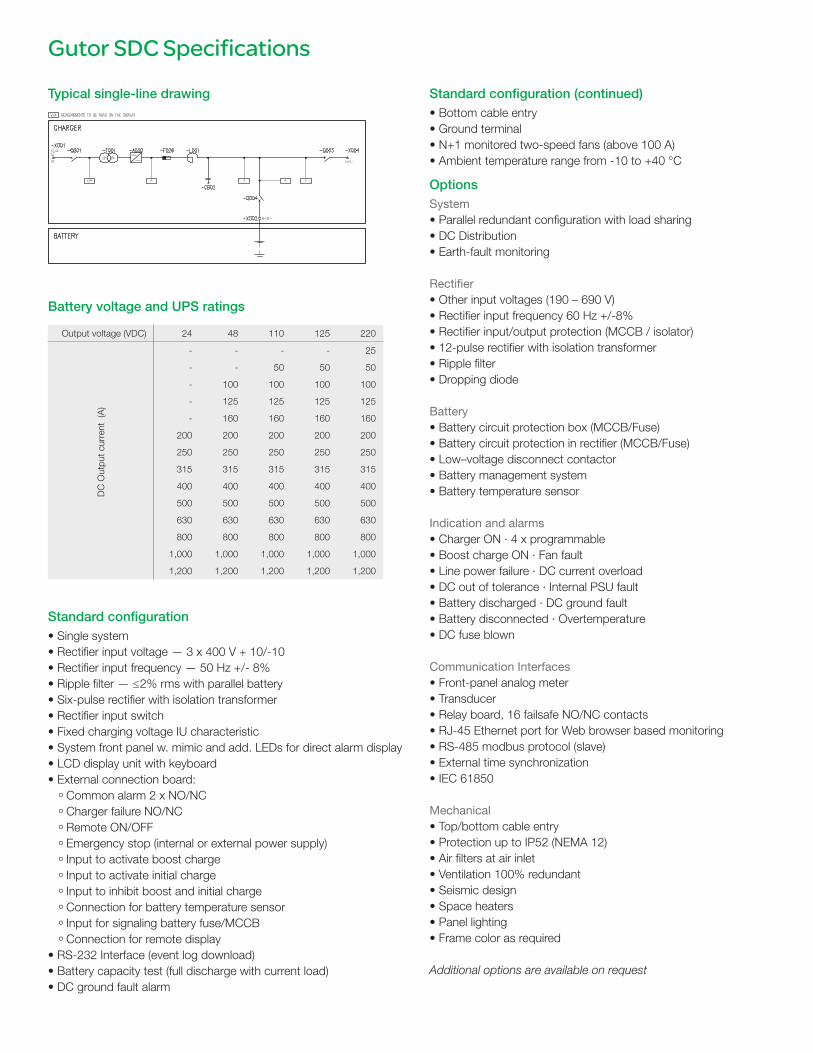
Output voltage (VDC) 24 48 110 125 220
- - - - 25
- - 50 50 50
DC
Out
put c
urre
nt (
A)
- 100 100 100 100
- 125 125 125 125
- 160 160 160 160
200 200 200 200 200
250 250 250 250 250
315 315 315 315 315
400 400 400 400 400
500 500 500 500 500
630 630 630 630 630
800 800 800 800 800
1,000 1,000 1,000 1,000 1,000
1,200 1,200 1,200 1,200 1,200
Gutor SDC Specifications
Typical single-line drawing
Battery voltage and UPS ratings
Standard configuration• Single system• Rectifier input voltage — 3 x 400 V + 10/-10• Rectifier input frequency — 50 Hz +/- 8%• Ripple filter — ≤ 2% rms with parallel battery• Six-pulse rectifier with isolation transformer• Rectifier input switch• Fixed charging voltage IU characteristic• System front panel w. mimic and add. LEDs for direct alarm display• LCD display unit with keyboard • External connection board:
º Common alarm 2 x NO/NC
º Charger failure NO/NC
º Remote ON/OFF
º Emergency stop (internal or external power supply)
º Input to activate boost charge
º Input to activate initial charge
º Input to inhibit boost and initial charge
º Connection for battery temperature sensor
º Input for signaling battery fuse/MCCB
º Connection for remote display • RS-232 Interface (event log download)• Battery capacity test (full discharge with current load)• DC ground fault alarm
Standard configuration (continued)• Bottom cable entry• Ground terminal • N+1 monitored two-speed fans (above 100 A)• Ambient temperature range from -10 to +40 °C
OptionsSystem• Parallel redundant configuration with load sharing• DC Distribution• Earth-fault monitoring
Rectifier• Other input voltages (190 – 690 V)• Rectifier input frequency 60 Hz +/-8%• Rectifier input/output protection (MCCB / isolator)• 12-pulse rectifier with isolation transformer• Ripple filter• Dropping diode
Battery• Battery circuit protection box (MCCB/Fuse)• Battery circuit protection in rectifier (MCCB/Fuse)• Low–voltage disconnect contactor• Battery management system • Battery temperature sensor
Indication and alarms• Charger ON · 4 x programmable• Boost charge ON · Fan fault• Line power failure · DC current overload• DC out of tolerance · Internal PSU fault• Battery discharged · DC ground fault• Battery disconnected · Overtemperature• DC fuse blown
Communication Interfaces • Front-panel analog meter• Transducer• Relay board, 16 failsafe NO/NC contacts• RJ-45 Ethernet port for Web browser based monitoring• RS-485 modbus protocol (slave)• External time synchronization• IEC 61850
Mechanical• Top/bottom cable entry• Protection up to IP52 (NEMA 12)• Air filters at air inlet• Ventilation 100% redundant• Seismic design• Space heaters• Panel lighting• Frame color as required
Additional options are available on request

Human-machine interface (front panel)
The front panel includes a comprehensive and flexible human-machine interface. It is divided into four sections:
1 The system panel shows the system’s current state of operation (i.e., which part of the system is currently supplying the load and which is in stand-by mode). LEDs also indicate possible faults.
2 Use the operations panel to turn the system on and off. The lamp-test button indicates whether all LED indication lights are functioning properly. To shut down the system, you have to press the ON and OFF buttons at the same time.
3 The display unit consists of a liquid crystal display, an alarm LED, an acoustic alarm, and a keypad. From here, the user can set operational parameters, obtain current measurement data, and access the event and alarm logs.
4 On the alarm indication panel, the respective LEDs light up to indicate a possible fault or after an alarm has occurred.
Operational parameters• Selectable second display language• Auto start• Charge mode (float/boost/initial)• Auto boost (charge)• Battery capacity test• Advanced battery monitor test (optional)• Set date/time
Indication and measurements• Operating mode (float/boost/initial)• DC total current• Battery voltage and current• AC rectifier line power voltage and current • Battery temperature (with optional sensor)• Time left in battery operation with current load (option only with advanced
battery monitoring)• Event log with date/time (operating mode changes and alarms)
1 2
3
4
Headquarters:Gutor Electronic LLC, Hardstrasse 72 – 74, 5430 Wettingen, SwitzerlandP +41 (0)56 437 34 34 | F +41 (0)56 437 34 44 | [email protected]
Malaysia production facilities:Gutor Electronic Asia Pacific Sdn.Bhd No.19, Jalan Juruukur U1/19, Seksyen U1, Hicom Glenmarie Ind Park, 40150 Shah Alam, Selangor Malaysia
Gutor North America:12121 Wickchester Lane Suite 400, Houston, Texas 77079, USAP +888-994-8867 | F +281-588-2199 | [email protected]
www.schneider-electric.com
©2014 Schneider Electric. All Rights Reserved. Schneider Electric and Gutor are trademarks owned by Schneider Electric Industries SAS or its affiliated companies. All other trademarks are the property of their respective owners. • 998-1218617_GMA-US