Embed Size (px)
Citation preview
Gutor PXC
10–80 kVA Parallel Redundant UPS System withCoupling Switches
Installation
10/2018
www.schneider-electric.com

Legal InformationThe Schneider Electric brand and any registered trademarks of Schneider ElectricIndustries SAS referred to in this guide are the sole property of Schneider Electric SAand its subsidiaries. They may not be used for any purpose without the owner'spermission, given in writing. This guide and its content are protected, within themeaning of the French intellectual property code (Code de la propriété intellectuellefrançais, referred to hereafter as "the Code"), under the laws of copyright coveringtexts, drawings and models, as well as by trademark law. You agree not to reproduce,other than for your own personal, noncommercial use as defined in the Code, all orpart of this guide on any medium whatsoever without Schneider Electric's permission,given in writing. You also agree not to establish any hypertext links to this guide or itscontent. Schneider Electric does not grant any right or license for the personal andnoncommercial use of the guide or its content, except for a non-exclusive license toconsult it on an "as is" basis, at your own risk. All other rights are reserved.
Electrical equipment should be installed, operated, serviced, and maintained only byqualified personnel. No responsibility is assumed by Schneider Electric for anyconsequences arising out of the use of this material.
As standards, specifications, and designs change from time to time, please ask forconfirmation of the information given in this publication.
10–80 kVA Parallel Redundant UPS System with CouplingSwitches
Table of Contents
Important Safety Instructions — SAVE THESEINSTRUCTIONS........................................................................................5
Electromagnetic Compatibility.....................................................................6Safety Precautions ....................................................................................6
Electrical Safety...................................................................................9Battery Safety....................................................................................10
Specifications ........................................................................................... 11Input Specifications.................................................................................. 11
Input Specifications for Systems without Transformer ........................... 11Input Specifications for Systems with Rectifier Input Transformer(T001)...............................................................................................12Input Specifications for Systems with Output Transformer(T401)...............................................................................................13Input Specifications for Systems with Rectifier Input Transformer(T001) and Inverter Output Transformer (T401) ....................................14
Bypass Specifications ..............................................................................15Bypass Specifications for Systems without Transformer........................15Bypass Specifications for Systems with Transformer (T501)..................16
Output Specifications ...............................................................................17Battery Specifications ..............................................................................19Required Upstream Protection..................................................................19Recommended Cable Sizes .....................................................................20Torque Specifications...............................................................................20Environment............................................................................................21
Heat Dissipation ................................................................................21UPS Weights and Dimensions ..................................................................22Battery Weights and Dimensions ..............................................................23Clearance ...............................................................................................24
System Overview .....................................................................................25
Installation Procedure for Bottom Cable Entry System......................27
Installation Procedure for Top Cable Entry System ............................29
Remove the Kick Plates..........................................................................31Mount the UPS System to the Floor......................................................32Prepare for Cables in Bottom Cable Entry System.............................35
Prepare for Cables in Top Cable Entry System...................................36
Connect the Power Cables on the 10-40 kVA ParallelRedundant System with Bottom Cable Entry.......................................38Connect the Power Cables on the 50–80 kVA ParallelRedundant System with Bottom Cable Entry.......................................40Connect the Power Cables on the 10-40 kVA ParallelRedundant System with Bottom Cable Entry and BypassTransformer ..............................................................................................42
990-6071-001 3
10–80 kVA Parallel Redundant UPS System with CouplingSwitches
Connect the Power Cables on the 50-80 kVA ParallelRedundant System with Bottom Cable Entry and BypassTransformer ..............................................................................................44Connect the Power Cables on the 10–80 kVA ParallelRedundant System with Top Cable Entry.............................................46Connect the Power Cables on the 10-40 kVA ParallelRedundant System with Top Cable Entry and BypassTransformer ..............................................................................................48Connect the Power Cables on the 50-80 kVA ParallelRedundant System with Top Cable Entry and BypassTransformer ..............................................................................................50Connect the Signal Cables .....................................................................52
Connect the Signal Cables for the Coupling Switches in ParallelRedundant Bottom Cable Entry System.....................................................56Connect the Signal Cables for the Coupling Switches in ParallelRedundant Top Cable Entry System..........................................................57
Reinstall the Kick Plates .........................................................................58
4 990-6071-001

Important Safety Instructions — SAVE THESEINSTRUCTIONS
10–80 kVA Parallel Redundant UPS System with CouplingSwitches
Important Safety Instructions — SAVE THESEINSTRUCTIONS
Read these instructions carefully and look at the equipment to become familiarwith it before trying to install, operate, service or maintain it. The following safetymessages may appear throughout this manual or on the equipment to warn ofpotential hazards or to call attention to information that clarifies or simplifies aprocedure.
The addition of this symbol to a “Danger” or “Warning” safetymessage indicates that an electrical hazard exists which will result inpersonal injury if the instructions are not followed.
This is the safety alert symbol. It is used to alert you to potentialpersonal injury hazards. Obey all safety messages with this symbolto avoid possible injury or death.
DANGERDANGER indicates a hazardous situation which, if not avoided, will result indeath or serious injury.
Failure to follow these instructions will result in death or serious injury.
WARNINGWARNING indicates a hazardous situation which, if not avoided, could resultin death or serious injury.
Failure to follow these instructions can result in death, serious injury, orequipment damage.
CAUTIONCAUTION indicates a hazardous situation which, if not avoided, could result inminor or moderate injury.
Failure to follow these instructions can result in injury or equipmentdamage.
NOTICENOTICE is used to address practices not related to physical injury. The safetyalert symbol shall not be used with this type of safety message.
Failure to follow these instructions can result in equipment damage.
Please NoteElectrical equipment should only be installed, operated, serviced, and maintainedby qualified personnel. No responsibility is assumed by Schneider Electric for anyconsequences arising out of the use of this material.
A qualified person is one who has skills and knowledge related to the construction,installation, and operation of electrical equipment and has received safety trainingto recognize and avoid the hazards involved.
990-6071-001 5
10–80 kVA Parallel Redundant UPS System with CouplingSwitches
Important Safety Instructions — SAVE THESEINSTRUCTIONS
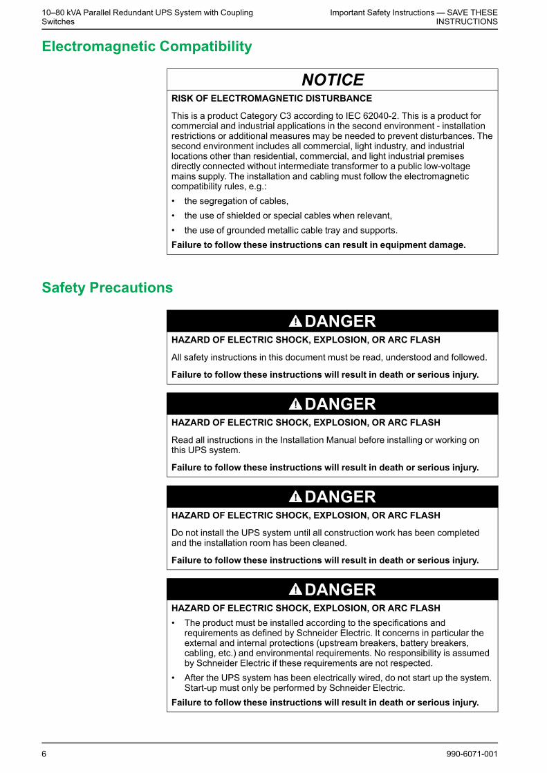
Electromagnetic Compatibility
NOTICERISK OF ELECTROMAGNETIC DISTURBANCE
This is a product Category C3 according to IEC 62040-2. This is a product forcommercial and industrial applications in the second environment - installationrestrictions or additional measures may be needed to prevent disturbances. Thesecond environment includes all commercial, light industry, and industriallocations other than residential, commercial, and light industrial premisesdirectly connected without intermediate transformer to a public low-voltagemains supply. The installation and cabling must follow the electromagneticcompatibility rules, e.g.:• the segregation of cables,• the use of shielded or special cables when relevant,• the use of grounded metallic cable tray and supports.Failure to follow these instructions can result in equipment damage.
Safety Precautions
DANGERHAZARD OF ELECTRIC SHOCK, EXPLOSION, OR ARC FLASH
All safety instructions in this document must be read, understood and followed.
Failure to follow these instructions will result in death or serious injury.
DANGERHAZARD OF ELECTRIC SHOCK, EXPLOSION, OR ARC FLASH
Read all instructions in the Installation Manual before installing or working onthis UPS system.
Failure to follow these instructions will result in death or serious injury.
DANGERHAZARD OF ELECTRIC SHOCK, EXPLOSION, OR ARC FLASH
Do not install the UPS system until all construction work has been completedand the installation room has been cleaned.
Failure to follow these instructions will result in death or serious injury.
DANGERHAZARD OF ELECTRIC SHOCK, EXPLOSION, OR ARC FLASH• The product must be installed according to the specifications and
requirements as defined by Schneider Electric. It concerns in particular theexternal and internal protections (upstream breakers, battery breakers,cabling, etc.) and environmental requirements. No responsibility is assumedby Schneider Electric if these requirements are not respected.
• After the UPS system has been electrically wired, do not start up the system.Start-up must only be performed by Schneider Electric.
Failure to follow these instructions will result in death or serious injury.
6 990-6071-001
Important Safety Instructions — SAVE THESEINSTRUCTIONS
10–80 kVA Parallel Redundant UPS System with CouplingSwitches
DANGERHAZARD OF ELECTRIC SHOCK, EXPLOSION, OR ARC FLASH
The UPS system must be installed according to local and national regulations.Install the UPS according to:• IEC 60364 (including 60364–4–41- protection against electric shock, 60364–
4–42 - protection against thermal effect, and 60364–4–43 - protectionagainst overcurrent), or
• NEC NFPA 70, or• Canadian Electrical Code (C22.1, Part 1)depending on which one of the standards apply in your local area.
Failure to follow these instructions will result in death or serious injury.
DANGERHAZARD OF ELECTRIC SHOCK, EXPLOSION, OR ARC FLASH• Install the UPS system in a temperature controlled indoor environment free
of conductive contaminants and humidity.• Install the UPS system on a non-flammable, level and solid surface (e.g.
concrete) that can support the weight of the system.Failure to follow these instructions will result in death or serious injury.
DANGERHAZARD OF ELECTRIC SHOCK, EXPLOSION, OR ARC FLASH
The UPS is not designed for and must therefore not be installed in the followingunusual operating environments:• Damaging fumes• Explosive mixtures of dust or gases, corrosive gases, or conductive or
radiant heat from other sources• Moisture, abrasive dust, steam or in an excessively damp environment• Fungus, insects, vermin• Salt-laden air or contaminated cooling refrigerant• Pollution degree higher than 2 according to IEC 60664-1• Exposure to abnormal vibrations, shocks, and tilting• Exposure to direct sunlight, heat sources, or strong electromagnetic fieldsFailure to follow these instructions will result in death or serious injury.
DANGERHAZARD OF ELECTRIC SHOCK, EXPLOSION, OR ARC FLASH
Do not drill or cut holes for cables or conduits with the gland plates installed anddo not drill or cut holes in close proximity to the UPS.
Failure to follow these instructions will result in death or serious injury.
WARNINGHAZARD OFARC FLASH
Do not make mechanical changes to the product (including removal of cabinetparts or drilling/cutting of holes) that are not described in the Installation Manual.
Failure to follow these instructions can result in death, serious injury, orequipment damage.
990-6071-001 7
10–80 kVA Parallel Redundant UPS System with CouplingSwitches
Important Safety Instructions — SAVE THESEINSTRUCTIONS
NOTICERISK OF OVERHEATING
Respect the space requirements around the UPS system and do not cover theproduct’s ventilation openings when the UPS system is in operation.
Failure to follow these instructions can result in equipment damage.
NOTICERISK OF EQUIPMENT DAMAGE
Do not connect the UPS output to regenerative load systems includingphotovoltaic systems and speed drives.
Failure to follow these instructions can result in equipment damage.
8 990-6071-001
Important Safety Instructions — SAVE THESEINSTRUCTIONS
10–80 kVA Parallel Redundant UPS System with CouplingSwitches
Electrical Safety
DANGERHAZARD OF ELECTRIC SHOCK, EXPLOSION OR ARC FLASH• Electrical equipment must be installed, operated, serviced, and maintained
only by qualified personnel.• The UPS system must be installed in a room with restricted access (qualified
personnel only).• Apply appropriate personal protective equipment (PPE) and follow safe
electrical work practices.• Turn off all power supplying the UPS system before working on or inside the
equipment.• Before working on the UPS system, check for hazardous voltage between all
terminals including the protective earth.• The UPS contains an internal energy source. Hazardous voltage can be
present even when disconnected from the utility/mains supply. Beforeinstalling or servicing the UPS system, ensure that the units are OFF andthat utility/mains and batteries are disconnected. Wait five minutes beforeopening the UPS to allow the capacitors to discharge.
• A disconnection device (e.g. disconnection circuit breaker or switch) must beinstalled to enable isolation of the system from upstream power sources inaccordance with local regulations. This disconnection device must be easilyaccessible and visible.
• The UPS must be properly earthed/grounded and due to a high leakagecurrent, the earthing/grounding conductor must be connected first.
Failure to follow these instructions will result in death or serious injury.
DANGERHAZARD OF ELECTRIC SHOCK, EXPLOSION, OR ARC FLASH
In systems where backfeed protection is not part of the standard design, anautomatic isolation device (backfeed protection option or other device meetingthe requirements of IEC/EN 62040–1 or UL1778 5th Edition – depending onwhich of the two standards apply to your local area) must be installed to preventhazardous voltage or energy at the input terminals of the isolation device. Thedevice must open within 15 seconds after the upstream power supply fails andmust be rated according to the specifications.
Failure to follow these instructions will result in death or serious injury.
When the UPS input is connected through external isolators that, when opened,isolate the neutral or when the automatic backfeed isolation is provided external tothe equipment or is connected to an IT power distribution system, a label must befitted at the UPS input terminals, and on all primary power isolators installedremote from the UPS area and on external access points between such isolatorsand the UPS, by the user, displaying the following text (or equivalent in a languagewhich is acceptable in the country in which the UPS system is installed):
DANGERHAZARD OF ELECTRIC SHOCK, EXPLOSION, OR ARC FLASH
Risk of Voltage Backfeed. Before working on this circuit: Isolate the UPS andcheck for hazardous voltage between all terminals including the protectiveearth.
Failure to follow these instructions will result in death or serious injury.
990-6071-001 9
10–80 kVA Parallel Redundant UPS System with CouplingSwitches
Important Safety Instructions — SAVE THESEINSTRUCTIONS
Battery Safety
DANGERHAZARD OF ELECTRIC SHOCK, EXPLOSION, OR ARC FLASH• Battery circuit breakers must be installed according to the specifications and
requirements as defined by Schneider Electric.• Servicing of batteries must only be performed or supervised by qualified
personnel knowledgeable of batteries and the required precautions. Keepunqualified personnel away from batteries.
• Disconnect charging source prior to connecting or disconnecting batteryterminals.
• Do not dispose of batteries in a fire as they can explode.• Do not open, alter, or mutilate batteries. Released electrolyte is harmful to
the skin and eyes. It may be toxic.Failure to follow these instructions will result in death or serious injury.
DANGERHAZARD OF ELECTRIC SHOCK, EXPLOSION, OR ARC FLASH
Batteries can present a risk of electric shock and high short-circuit current. Thefollowing precautions must be observed when working on batteries• Remove watches, rings, or other metal objects.• Use tools with insulated handles.• Wear protective glasses, gloves and boots.• Do not lay tools or metal parts on top of batteries.• Disconnect the charging source prior to connecting or disconnecting battery
terminals.• Determine if the battery is inadvertently grounded. If inadvertently grounded,
remove source from ground. Contact with any part of a grounded battery canresult in electric shock. The likelihood of such shock can be reduced if suchgrounds are removed during installation and maintenance (applicable toequipment and remote battery supplies not having a grounded supplycircuit).
Failure to follow these instructions will result in death or serious injury.
DANGERHAZARD OF ELECTRIC SHOCK, EXPLOSION, OR ARC FLASH
When replacing batteries, always replace with the same type and number ofbatteries or battery packs.
Failure to follow these instructions will result in death or serious injury.
NOTICERISK OF EQUIPMENT DAMAGE• Wait until the system is ready to be powered up before installing batteries in
the system. The time duration from battery installation until the UPS systemis powered up must not exceed 72 hours or 3 days.
• Batteries must not be stored more than six months due to the requirement ofrecharging. If the UPS system remains de-energized for a long period,Schneider Electric recommends that you energize the UPS system for aperiod of 24 hours at least once every month. This charges the batteries,thus avoiding irreversible damage.
Failure to follow these instructions can result in equipment damage.
10 990-6071-001
Specifications10–80 kVA Parallel Redundant UPS System with Coupling
Switches
Specifications
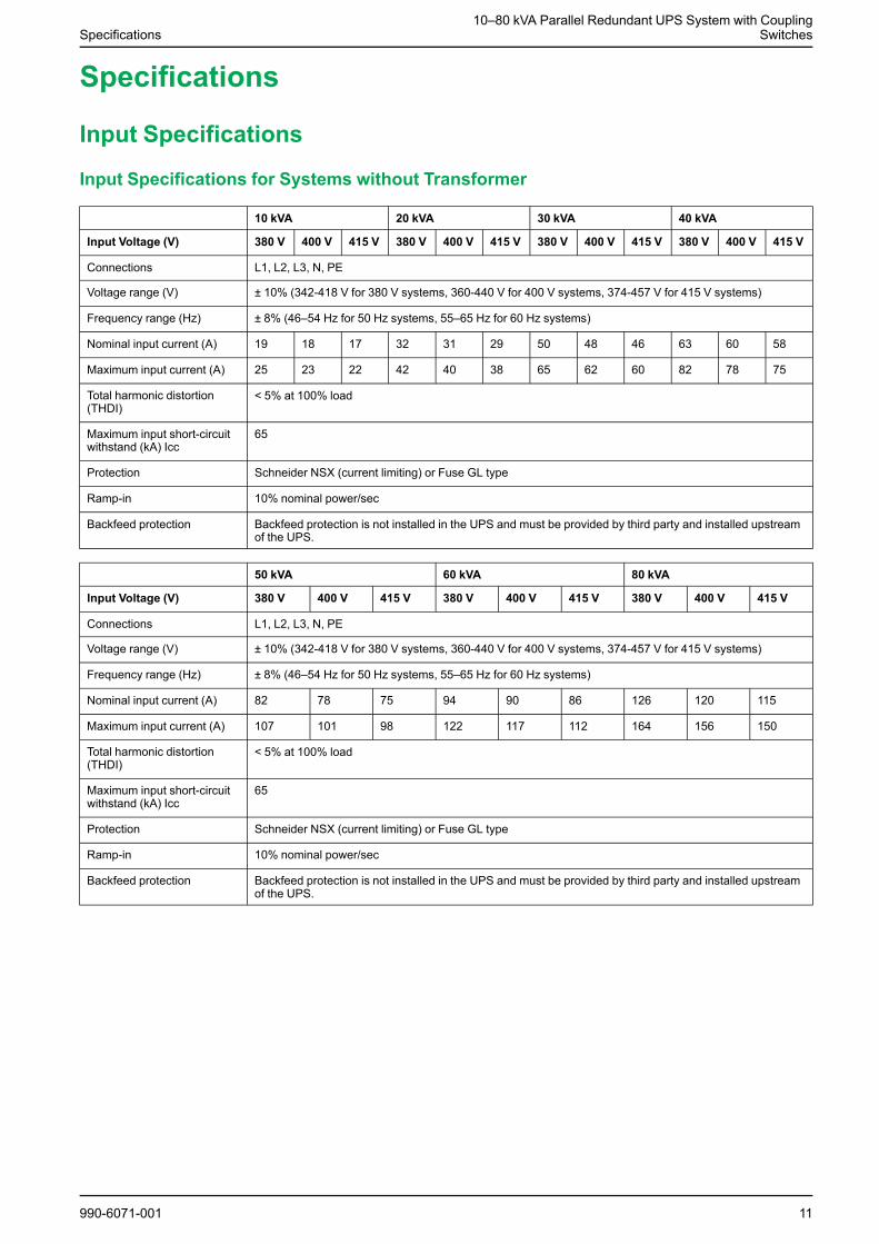
Input Specifications
Input Specifications for Systems without Transformer
10 kVA 20 kVA 30 kVA 40 kVA
Input Voltage (V) 380 V 400 V 415 V 380 V 400 V 415 V 380 V 400 V 415 V 380 V 400 V 415 V
Connections L1, L2, L3, N, PE
Voltage range (V) ± 10% (342-418 V for 380 V systems, 360-440 V for 400 V systems, 374-457 V for 415 V systems)
Frequency range (Hz) ± 8% (46–54 Hz for 50 Hz systems, 55–65 Hz for 60 Hz systems)
Nominal input current (A) 19 18 17 32 31 29 50 48 46 63 60 58
Maximum input current (A) 25 23 22 42 40 38 65 62 60 82 78 75
Total harmonic distortion(THDI)
< 5% at 100% load
Maximum input short-circuitwithstand (kA) Icc
65
Protection Schneider NSX (current limiting) or Fuse GL type
Ramp-in 10% nominal power/sec
Backfeed protection Backfeed protection is not installed in the UPS and must be provided by third party and installed upstreamof the UPS.
50 kVA 60 kVA 80 kVA
Input Voltage (V) 380 V 400 V 415 V 380 V 400 V 415 V 380 V 400 V 415 V
Connections L1, L2, L3, N, PE
Voltage range (V) ± 10% (342-418 V for 380 V systems, 360-440 V for 400 V systems, 374-457 V for 415 V systems)
Frequency range (Hz) ± 8% (46–54 Hz for 50 Hz systems, 55–65 Hz for 60 Hz systems)
Nominal input current (A) 82 78 75 94 90 86 126 120 115
Maximum input current (A) 107 101 98 122 117 112 164 156 150
Total harmonic distortion(THDI)
< 5% at 100% load
Maximum input short-circuitwithstand (kA) Icc
65
Protection Schneider NSX (current limiting) or Fuse GL type
Ramp-in 10% nominal power/sec
Backfeed protection Backfeed protection is not installed in the UPS and must be provided by third party and installed upstreamof the UPS.
990-6071-001 11
10–80 kVA Parallel Redundant UPS System with CouplingSwitches Specifications
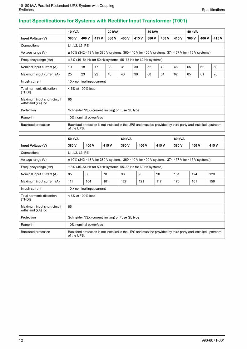
Input Specifications for Systems with Rectifier Input Transformer (T001)
10 kVA 20 kVA 30 kVA 40 kVA
Input Voltage (V) 380 V 400 V 415 V 380 V 400 V 415 V 380 V 400 V 415 V 380 V 400 V 415 V
Connections L1, L2, L3, PE
Voltage range (V) ± 10% (342-418 V for 380 V systems, 360-440 V for 400 V systems, 374-457 V for 415 V systems)
Frequency range (Hz) ± 8% (46–54 Hz for 50 Hz systems, 55–65 Hz for 60 Hz systems)
Nominal input current (A) 19 18 17 33 31 30 52 49 48 65 62 60
Maximum input current (A) 25 23 22 43 40 39 68 64 62 85 81 78
Inrush current 10 x nominal input current
Total harmonic distortion(THDI)
< 5% at 100% load
Maximum input short-circuitwithstand (kA) Icc
65
Protection Schneider NSX (current limiting) or Fuse GL type
Ramp-in 10% nominal power/sec
Backfeed protection Backfeed protection is not installed in the UPS and must be provided by third party and installed upstreamof the UPS.
50 kVA 60 kVA 80 kVA
Input Voltage (V) 380 V 400 V 415 V 380 V 400 V 415 V 380 V 400 V 415 V
Connections L1, L2, L3, PE
Voltage range (V) ± 10% (342-418 V for 380 V systems, 360-440 V for 400 V systems, 374-457 V for 415 V systems)
Frequency range (Hz) ± 8% (46–54 Hz for 50 Hz systems, 55–65 Hz for 60 Hz systems)
Nominal input current (A) 85 80 78 98 93 90 131 124 120
Maximum input current (A) 111 104 101 127 121 117 170 161 156
Inrush current 10 x nominal input current
Total harmonic distortion(THDI)
< 5% at 100% load
Maximum input short-circuitwithstand (kA) Icc
65
Protection Schneider NSX (current limiting) or Fuse GL type
Ramp-in 10% nominal power/sec
Backfeed protection Backfeed protection is not installed in the UPS and must be provided by third party and installed upstreamof the UPS.
12 990-6071-001
Specifications10–80 kVA Parallel Redundant UPS System with Coupling
Switches
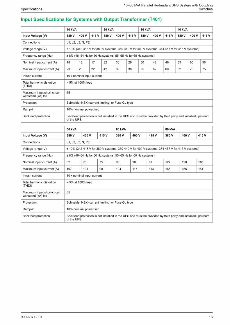
Input Specifications for Systems with Output Transformer (T401)
10 kVA 20 kVA 30 kVA 40 kVA
Input Voltage (V) 380 V 400 V 415 V 380 V 400 V 415 V 380 V 400 V 415 V 380 V 400 V 415 V
Connections L1, L2, L3, N, PE
Voltage range (V) ± 10% (342-418 V for 380 V systems, 360-440 V for 400 V systems, 374-457 V for 415 V systems)
Frequency range (Hz) ± 8% (46–54 Hz for 50 Hz systems, 55–65 Hz for 60 Hz systems)
Nominal input current (A) 18 18 17 32 30 29 50 48 46 63 60 58
Maximum input current (A) 23 23 22 42 39 38 65 62 60 82 78 75
Inrush current 10 x nominal input current
Total harmonic distortion(THDI)
< 5% at 100% load
Maximum input short-circuitwithstand (kA) Icc
65
Protection Schneider NSX (current limiting) or Fuse GL type
Ramp-in 10% nominal power/sec
Backfeed protection Backfeed protection is not installed in the UPS and must be provided by third party and installed upstreamof the UPS.
50 kVA 60 kVA 80 kVA
Input Voltage (V) 380 V 400 V 415 V 380 V 400 V 415 V 380 V 400 V 415 V
Connections L1, L2, L3, N, PE
Voltage range (V) ± 10% (342-418 V for 380 V systems, 360-440 V for 400 V systems, 374-457 V for 415 V systems)
Frequency range (Hz) ± 8% (46–54 Hz for 50 Hz systems, 55–65 Hz for 60 Hz systems)
Nominal input current (A) 82 78 75 95 90 87 127 120 116
Maximum input current (A) 107 101 98 124 117 113 165 156 151
Inrush current 10 x nominal input current
Total harmonic distortion(THDI)
< 5% at 100% load
Maximum input short-circuitwithstand (kA) Icc
65
Protection Schneider NSX (current limiting) or Fuse GL type
Ramp-in 10% nominal power/sec
Backfeed protection Backfeed protection is not installed in the UPS and must be provided by third party and installed upstreamof the UPS.
990-6071-001 13
10–80 kVA Parallel Redundant UPS System with CouplingSwitches Specifications
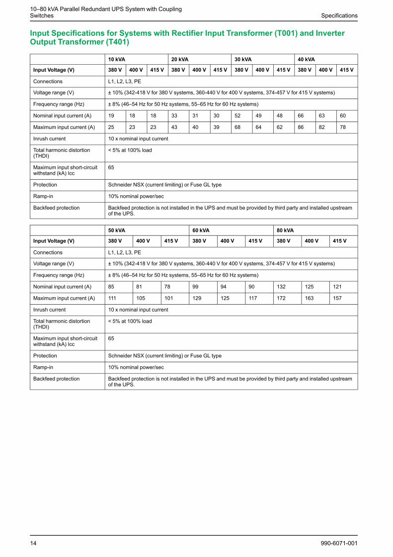
Input Specifications for Systems with Rectifier Input Transformer (T001) and InverterOutput Transformer (T401)
10 kVA 20 kVA 30 kVA 40 kVA
Input Voltage (V) 380 V 400 V 415 V 380 V 400 V 415 V 380 V 400 V 415 V 380 V 400 V 415 V
Connections L1, L2, L3, PE
Voltage range (V) ± 10% (342-418 V for 380 V systems, 360-440 V for 400 V systems, 374-457 V for 415 V systems)
Frequency range (Hz) ± 8% (46–54 Hz for 50 Hz systems, 55–65 Hz for 60 Hz systems)
Nominal input current (A) 19 18 18 33 31 30 52 49 48 66 63 60
Maximum input current (A) 25 23 23 43 40 39 68 64 62 86 82 78
Inrush current 10 x nominal input current
Total harmonic distortion(THDI)
< 5% at 100% load
Maximum input short-circuitwithstand (kA) Icc
65
Protection Schneider NSX (current limiting) or Fuse GL type
Ramp-in 10% nominal power/sec
Backfeed protection Backfeed protection is not installed in the UPS and must be provided by third party and installed upstreamof the UPS.
50 kVA 60 kVA 80 kVA
Input Voltage (V) 380 V 400 V 415 V 380 V 400 V 415 V 380 V 400 V 415 V
Connections L1, L2, L3, PE
Voltage range (V) ± 10% (342-418 V for 380 V systems, 360-440 V for 400 V systems, 374-457 V for 415 V systems)
Frequency range (Hz) ± 8% (46–54 Hz for 50 Hz systems, 55–65 Hz for 60 Hz systems)
Nominal input current (A) 85 81 78 99 94 90 132 125 121
Maximum input current (A) 111 105 101 129 125 117 172 163 157
Inrush current 10 x nominal input current
Total harmonic distortion(THDI)
< 5% at 100% load
Maximum input short-circuitwithstand (kA) Icc
65
Protection Schneider NSX (current limiting) or Fuse GL type
Ramp-in 10% nominal power/sec
Backfeed protection Backfeed protection is not installed in the UPS and must be provided by third party and installed upstreamof the UPS.
14 990-6071-001
Specifications10–80 kVA Parallel Redundant UPS System with Coupling
Switches
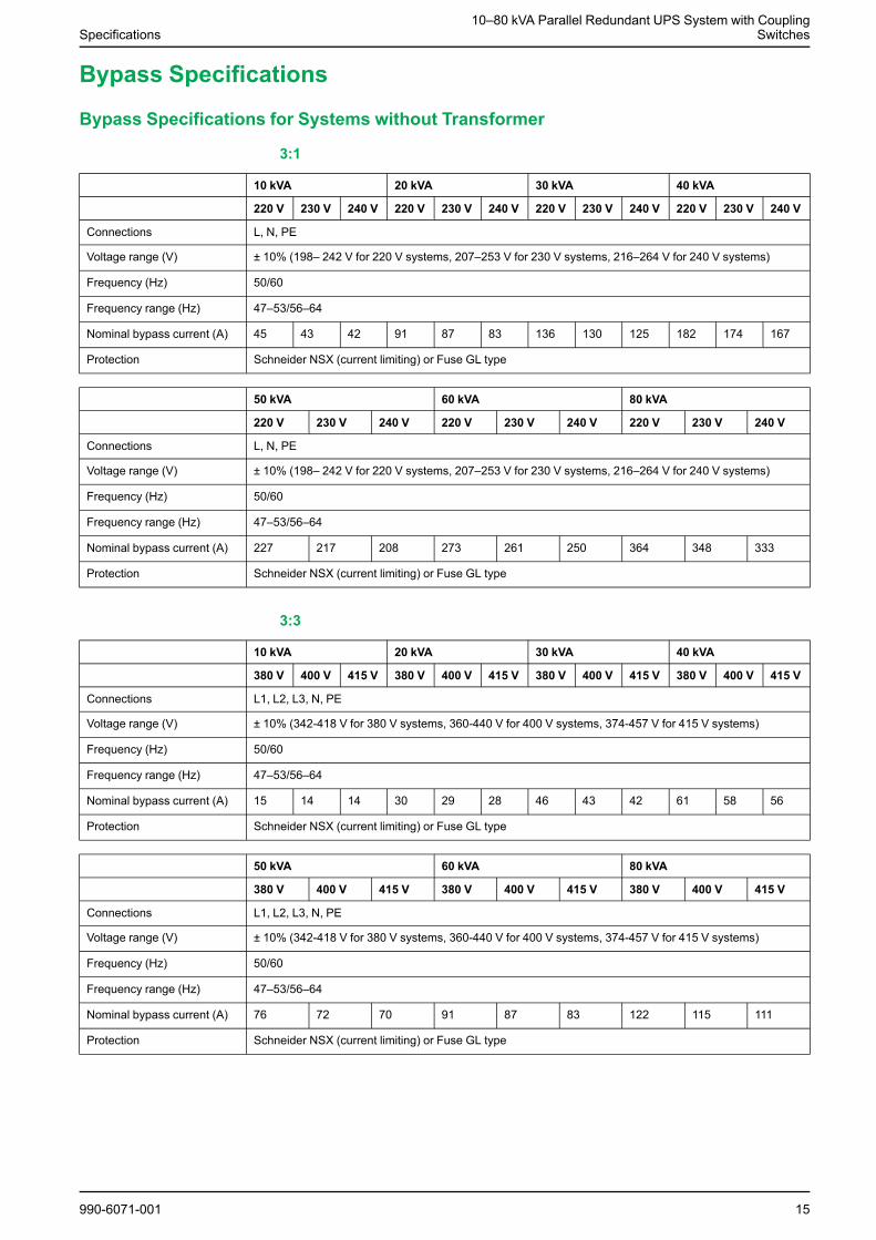
Bypass Specifications
Bypass Specifications for Systems without Transformer
3:1
10 kVA 20 kVA 30 kVA 40 kVA
220 V 230 V 240 V 220 V 230 V 240 V 220 V 230 V 240 V 220 V 230 V 240 V
Connections L, N, PE
Voltage range (V) ± 10% (198– 242 V for 220 V systems, 207–253 V for 230 V systems, 216–264 V for 240 V systems)
Frequency (Hz) 50/60
Frequency range (Hz) 47–53/56–64
Nominal bypass current (A) 45 43 42 91 87 83 136 130 125 182 174 167
Protection Schneider NSX (current limiting) or Fuse GL type
50 kVA 60 kVA 80 kVA
220 V 230 V 240 V 220 V 230 V 240 V 220 V 230 V 240 V
Connections L, N, PE
Voltage range (V) ± 10% (198– 242 V for 220 V systems, 207–253 V for 230 V systems, 216–264 V for 240 V systems)
Frequency (Hz) 50/60
Frequency range (Hz) 47–53/56–64
Nominal bypass current (A) 227 217 208 273 261 250 364 348 333
Protection Schneider NSX (current limiting) or Fuse GL type
3:3
10 kVA 20 kVA 30 kVA 40 kVA
380 V 400 V 415 V 380 V 400 V 415 V 380 V 400 V 415 V 380 V 400 V 415 V
Connections L1, L2, L3, N, PE
Voltage range (V) ± 10% (342-418 V for 380 V systems, 360-440 V for 400 V systems, 374-457 V for 415 V systems)
Frequency (Hz) 50/60
Frequency range (Hz) 47–53/56–64
Nominal bypass current (A) 15 14 14 30 29 28 46 43 42 61 58 56
Protection Schneider NSX (current limiting) or Fuse GL type
50 kVA 60 kVA 80 kVA
380 V 400 V 415 V 380 V 400 V 415 V 380 V 400 V 415 V
Connections L1, L2, L3, N, PE
Voltage range (V) ± 10% (342-418 V for 380 V systems, 360-440 V for 400 V systems, 374-457 V for 415 V systems)
Frequency (Hz) 50/60
Frequency range (Hz) 47–53/56–64
Nominal bypass current (A) 76 72 70 91 87 83 122 115 111
Protection Schneider NSX (current limiting) or Fuse GL type
990-6071-001 15
10–80 kVA Parallel Redundant UPS System with CouplingSwitches Specifications
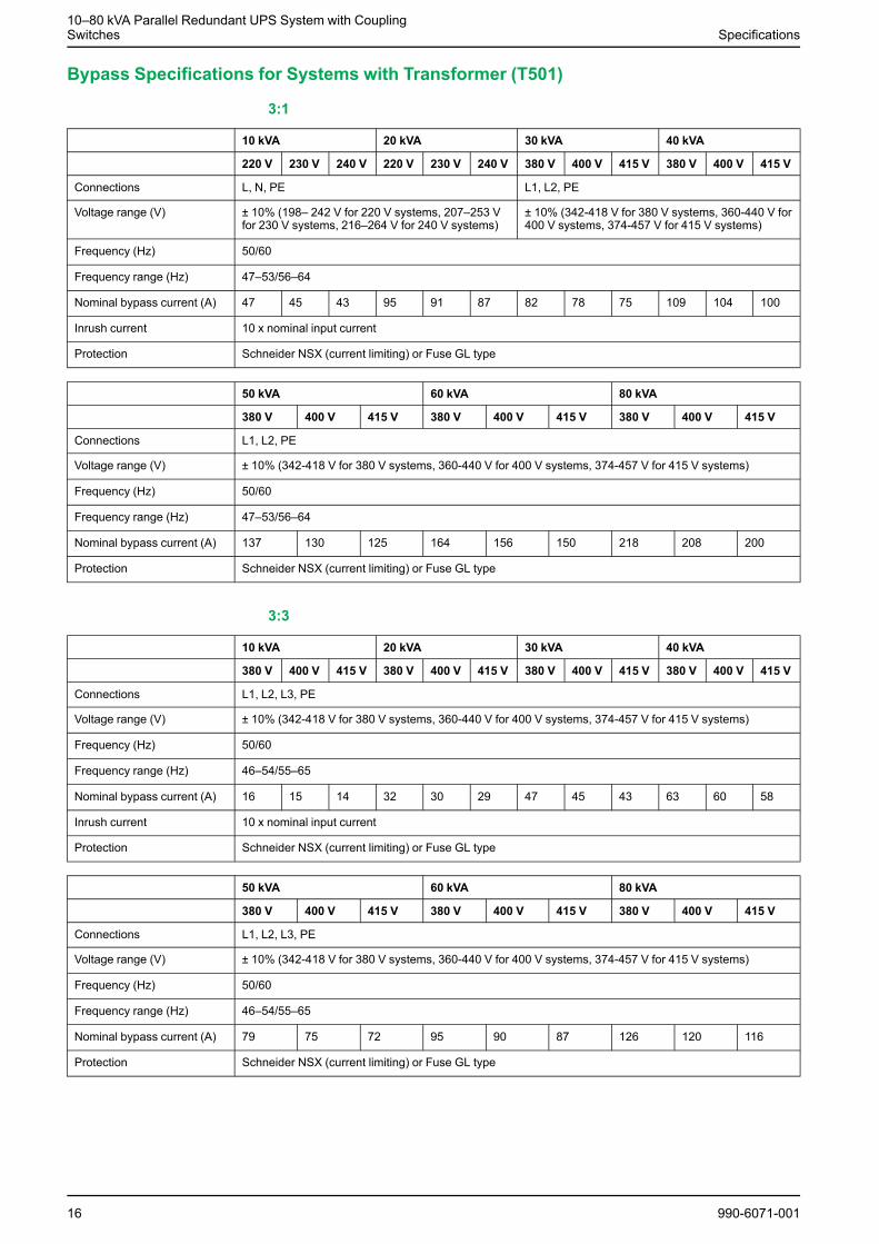
Bypass Specifications for Systems with Transformer (T501)
3:1
10 kVA 20 kVA 30 kVA 40 kVA
220 V 230 V 240 V 220 V 230 V 240 V 380 V 400 V 415 V 380 V 400 V 415 V
Connections L, N, PE L1, L2, PE
Voltage range (V) ± 10% (198– 242 V for 220 V systems, 207–253 Vfor 230 V systems, 216–264 V for 240 V systems)
± 10% (342-418 V for 380 V systems, 360-440 V for400 V systems, 374-457 V for 415 V systems)
Frequency (Hz) 50/60
Frequency range (Hz) 47–53/56–64
Nominal bypass current (A) 47 45 43 95 91 87 82 78 75 109 104 100
Inrush current 10 x nominal input current
Protection Schneider NSX (current limiting) or Fuse GL type
50 kVA 60 kVA 80 kVA
380 V 400 V 415 V 380 V 400 V 415 V 380 V 400 V 415 V
Connections L1, L2, PE
Voltage range (V) ± 10% (342-418 V for 380 V systems, 360-440 V for 400 V systems, 374-457 V for 415 V systems)
Frequency (Hz) 50/60
Frequency range (Hz) 47–53/56–64
Nominal bypass current (A) 137 130 125 164 156 150 218 208 200
Protection Schneider NSX (current limiting) or Fuse GL type
3:3
10 kVA 20 kVA 30 kVA 40 kVA
380 V 400 V 415 V 380 V 400 V 415 V 380 V 400 V 415 V 380 V 400 V 415 V
Connections L1, L2, L3, PE
Voltage range (V) ± 10% (342-418 V for 380 V systems, 360-440 V for 400 V systems, 374-457 V for 415 V systems)
Frequency (Hz) 50/60
Frequency range (Hz) 46–54/55–65
Nominal bypass current (A) 16 15 14 32 30 29 47 45 43 63 60 58
Inrush current 10 x nominal input current
Protection Schneider NSX (current limiting) or Fuse GL type
50 kVA 60 kVA 80 kVA
380 V 400 V 415 V 380 V 400 V 415 V 380 V 400 V 415 V
Connections L1, L2, L3, PE
Voltage range (V) ± 10% (342-418 V for 380 V systems, 360-440 V for 400 V systems, 374-457 V for 415 V systems)
Frequency (Hz) 50/60
Frequency range (Hz) 46–54/55–65
Nominal bypass current (A) 79 75 72 95 90 87 126 120 116
Protection Schneider NSX (current limiting) or Fuse GL type
16 990-6071-001
Specifications10–80 kVA Parallel Redundant UPS System with Coupling
Switches
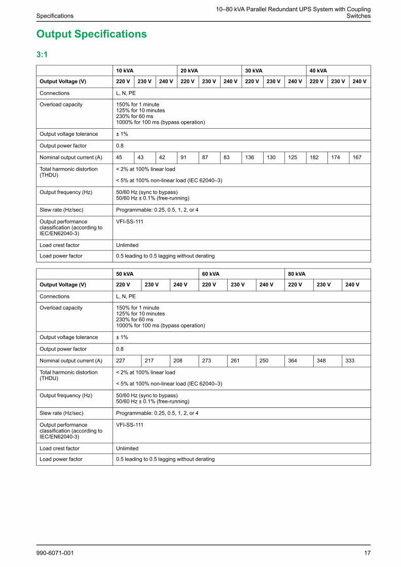
Output Specifications
3:1
10 kVA 20 kVA 30 kVA 40 kVA
Output Voltage (V) 220 V 230 V 240 V 220 V 230 V 240 V 220 V 230 V 240 V 220 V 230 V 240 V
Connections L, N, PE
Overload capacity 150% for 1 minute125% for 10 minutes230% for 60 ms1000% for 100 ms (bypass operation)
Output voltage tolerance ± 1%
Output power factor 0.8
Nominal output current (A) 45 43 42 91 87 83 136 130 125 182 174 167
Total harmonic distortion(THDU)
< 2% at 100% linear load
< 5% at 100% non-linear load (IEC 62040–3)
Output frequency (Hz) 50/60 Hz (sync to bypass)50/60 Hz ± 0.1% (free-running)
Slew rate (Hz/sec) Programmable: 0.25, 0.5, 1, 2, or 4
Output performanceclassification (according toIEC/EN62040-3)
VFI-SS-111
Load crest factor Unlimited
Load power factor 0.5 leading to 0.5 lagging without derating
50 kVA 60 kVA 80 kVA
Output Voltage (V) 220 V 230 V 240 V 220 V 230 V 240 V 220 V 230 V 240 V
Connections L, N, PE
Overload capacity 150% for 1 minute125% for 10 minutes230% for 60 ms1000% for 100 ms (bypass operation)
Output voltage tolerance ± 1%
Output power factor 0.8
Nominal output current (A) 227 217 208 273 261 250 364 348 333
Total harmonic distortion(THDU)
< 2% at 100% linear load
< 5% at 100% non-linear load (IEC 62040–3)
Output frequency (Hz) 50/60 Hz (sync to bypass)50/60 Hz ± 0.1% (free-running)
Slew rate (Hz/sec) Programmable: 0.25, 0.5, 1, 2, or 4
Output performanceclassification (according toIEC/EN62040-3)
VFI-SS-111
Load crest factor Unlimited
Load power factor 0.5 leading to 0.5 lagging without derating
990-6071-001 17
10–80 kVA Parallel Redundant UPS System with CouplingSwitches Specifications
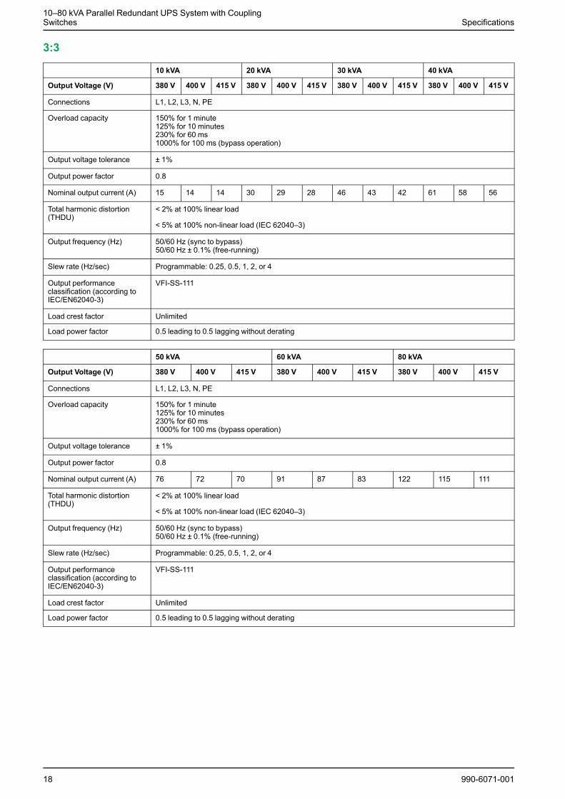
3:3
10 kVA 20 kVA 30 kVA 40 kVA
Output Voltage (V) 380 V 400 V 415 V 380 V 400 V 415 V 380 V 400 V 415 V 380 V 400 V 415 V
Connections L1, L2, L3, N, PE
Overload capacity 150% for 1 minute125% for 10 minutes230% for 60 ms1000% for 100 ms (bypass operation)
Output voltage tolerance ± 1%
Output power factor 0.8
Nominal output current (A) 15 14 14 30 29 28 46 43 42 61 58 56
Total harmonic distortion(THDU)
< 2% at 100% linear load
< 5% at 100% non-linear load (IEC 62040–3)
Output frequency (Hz) 50/60 Hz (sync to bypass)50/60 Hz ± 0.1% (free-running)
Slew rate (Hz/sec) Programmable: 0.25, 0.5, 1, 2, or 4
Output performanceclassification (according toIEC/EN62040-3)
VFI-SS-111
Load crest factor Unlimited
Load power factor 0.5 leading to 0.5 lagging without derating
50 kVA 60 kVA 80 kVA
Output Voltage (V) 380 V 400 V 415 V 380 V 400 V 415 V 380 V 400 V 415 V
Connections L1, L2, L3, N, PE
Overload capacity 150% for 1 minute125% for 10 minutes230% for 60 ms1000% for 100 ms (bypass operation)
Output voltage tolerance ± 1%
Output power factor 0.8
Nominal output current (A) 76 72 70 91 87 83 122 115 111
Total harmonic distortion(THDU)
< 2% at 100% linear load
< 5% at 100% non-linear load (IEC 62040–3)
Output frequency (Hz) 50/60 Hz (sync to bypass)50/60 Hz ± 0.1% (free-running)
Slew rate (Hz/sec) Programmable: 0.25, 0.5, 1, 2, or 4
Output performanceclassification (according toIEC/EN62040-3)
VFI-SS-111
Load crest factor Unlimited
Load power factor 0.5 leading to 0.5 lagging without derating
18 990-6071-001
Specifications10–80 kVA Parallel Redundant UPS System with Coupling
Switches
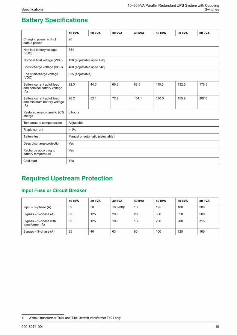
Battery Specifications
10 kVA 20 kVA 30 kVA 40 kVA 50 kVA 60 kVA 80 kVA
Charging power in % ofoutput power
20
Nominal battery voltage(VDC)
384
Nominal float voltage (VDC) 436 (adjustable up to 490)
Boost charge voltage (VDC) 480 (adjustable up to 540)
End of discharge voltage(VDC)
335 (adjustable)
Battery current at full loadand nominal battery voltage(A)
22.3 44.3 66.3 88.5 110.5 132.5 176.5
Battery current at full loadand minimum battery voltage(A)
26.2 52.1 77.9 104.1 130.0 155.9 207.6
Restored energy time to 90%charge
8 hours
Temperature compensation Adjustable
Ripple current < 1%
Battery test Manual or automatic (selectable)
Deep discharge protection Yes
Recharge according tobattery temperature
Yes
Cold start Yes
Required Upstream Protection
Input Fuse or Circuit Breaker
10 kVA 20 kVA 30 kVA 40 kVA 50 kVA 60 kVA 80 kVA
Input – 3–phase (A) 32 50 100 (80)1 100 125 160 200
Bypass – 1–phase (A) 63 125 200 250 300 350 500
Bypass – 1–phase withtransformer (A)
63 125 100 160 200 200 315
Bypass – 3–phase (A) 25 40 63 80 100 125 160
990-6071-001 19
1. Without transformer T001 and T401 or with transformer T401 only
10–80 kVA Parallel Redundant UPS System with CouplingSwitches Specifications
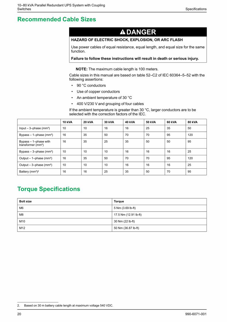
Recommended Cable Sizes
DANGERHAZARD OF ELECTRIC SHOCK, EXPLOSION, OR ARC FLASH
Use power cables of equal resistance, equal length, and equal size for the samefunction.
Failure to follow these instructions will result in death or serious injury.
NOTE: The maximum cable length is 100 meters.Cable sizes in this manual are based on table 52–C2 of IEC 60364–5–52 with thefollowing assertions:• 90 °C conductors• Use of copper conductors• An ambient temperature of 30 °C• 400 V/230 V and grouping of four cablesIf the ambient temperature is greater than 30 °C, larger conductors are to beselected with the correction factors of the IEC.
10 kVA 20 kVA 30 kVA 40 kVA 50 kVA 60 kVA 80 kVA
Input – 3–phase (mm²) 10 10 16 16 25 35 50
Bypass – 1–phase (mm²) 16 35 50 70 70 95 120
Bypass – 1–phase withtransformer (mm²)
16 35 25 35 50 50 95
Bypass – 3–phase (mm²) 10 10 10 16 16 16 25
Output – 1–phase (mm²) 16 35 50 70 70 95 120
Output – 3–phase (mm²) 10 10 10 16 16 16 25
Battery (mm²)2 16 16 25 35 50 70 95
Torque Specifications
Bolt size Torque
M6 5 Nm (3.69 lb-ft)
M8 17.5 Nm (12.91 lb-ft)
M10 30 Nm (22 lb-ft)
M12 50 Nm (36.87 lb-ft)
20 990-6071-001
2. Based on 30 m battery cable length at maximum voltage 540 VDC.
Specifications10–80 kVA Parallel Redundant UPS System with Coupling
Switches
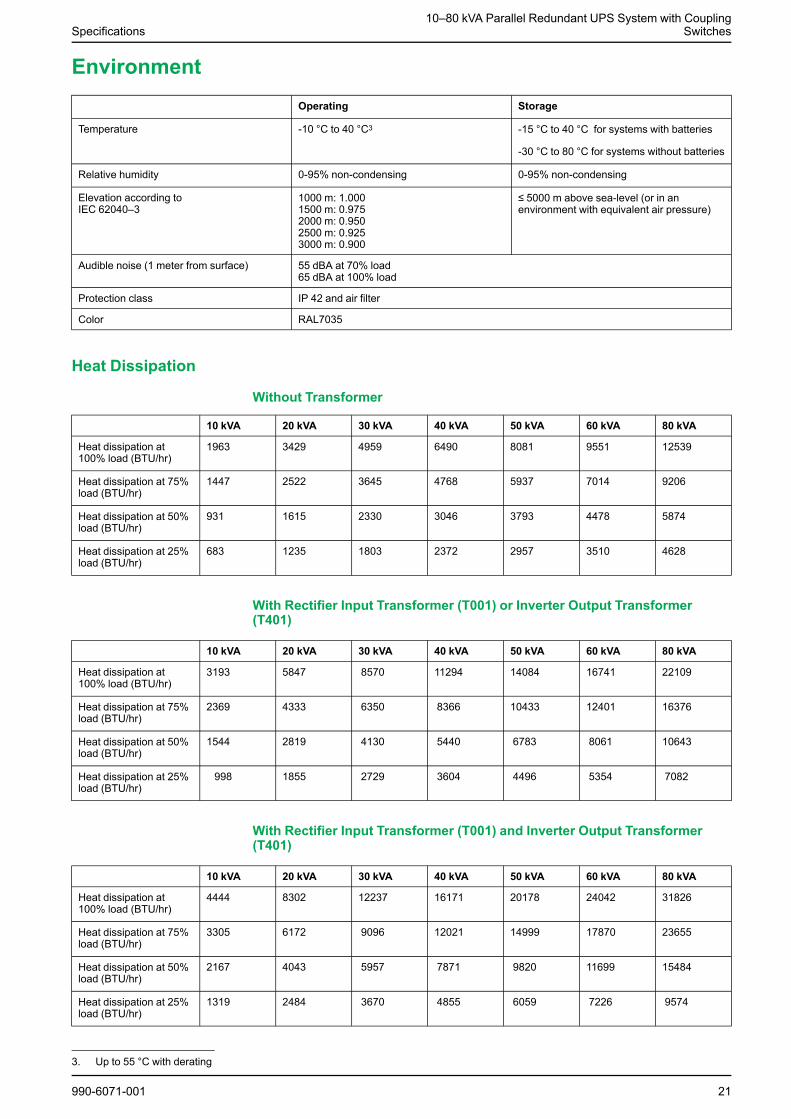
EnvironmentOperating Storage
Temperature -10 °C to 40 °C3 -15 °C to 40 °C for systems with batteries
-30 °C to 80 °C for systems without batteries
Relative humidity 0-95% non-condensing 0-95% non-condensing
Elevation according toIEC 62040–3
1000 m: 1.0001500 m: 0.9752000 m: 0.9502500 m: 0.9253000 m: 0.900
≤ 5000 m above sea-level (or in anenvironment with equivalent air pressure)
Audible noise (1 meter from surface) 55 dBA at 70% load65 dBA at 100% load
Protection class IP 42 and air filter
Color RAL7035
Heat Dissipation
Without Transformer
10 kVA 20 kVA 30 kVA 40 kVA 50 kVA 60 kVA 80 kVA
Heat dissipation at100% load (BTU/hr)
1963 3429 4959 6490 8081 9551 12539
Heat dissipation at 75%load (BTU/hr)
1447 2522 3645 4768 5937 7014 9206
Heat dissipation at 50%load (BTU/hr)
931 1615 2330 3046 3793 4478 5874
Heat dissipation at 25%load (BTU/hr)
683 1235 1803 2372 2957 3510 4628
With Rectifier Input Transformer (T001) or Inverter Output Transformer(T401)
10 kVA 20 kVA 30 kVA 40 kVA 50 kVA 60 kVA 80 kVA
Heat dissipation at100% load (BTU/hr)
3193 5847 8570 11294 14084 16741 22109
Heat dissipation at 75%load (BTU/hr)
2369 4333 6350 8366 10433 12401 16376
Heat dissipation at 50%load (BTU/hr)
1544 2819 4130 5440 6783 8061 10643
Heat dissipation at 25%load (BTU/hr)
998 1855 2729 3604 4496 5354 7082
With Rectifier Input Transformer (T001) and Inverter Output Transformer(T401)
10 kVA 20 kVA 30 kVA 40 kVA 50 kVA 60 kVA 80 kVA
Heat dissipation at100% load (BTU/hr)
4444 8302 12237 16171 20178 24042 31826
Heat dissipation at 75%load (BTU/hr)
3305 6172 9096 12021 14999 17870 23655
Heat dissipation at 50%load (BTU/hr)
2167 4043 5957 7871 9820 11699 15484
Heat dissipation at 25%load (BTU/hr)
1319 2484 3670 4855 6059 7226 9574
990-6071-001 21
3. Up to 55 °C with derating
10–80 kVA Parallel Redundant UPS System with CouplingSwitches Specifications
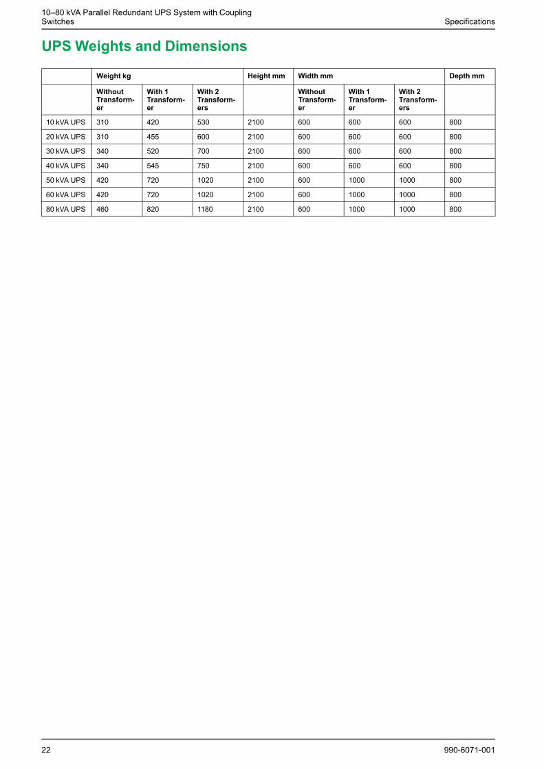
UPS Weights and Dimensions
Weight kg Height mm Width mm Depth mm
WithoutTransform-er
With 1Transform-er
With 2Transform-ers
WithoutTransform-er
With 1Transform-er
With 2Transform-ers
10 kVA UPS 310 420 530 2100 600 600 600 800
20 kVA UPS 310 455 600 2100 600 600 600 800
30 kVA UPS 340 520 700 2100 600 600 600 800
40 kVA UPS 340 545 750 2100 600 600 600 800
50 kVA UPS 420 720 1020 2100 600 1000 1000 800
60 kVA UPS 420 720 1020 2100 600 1000 1000 800
80 kVA UPS 460 820 1180 2100 600 1000 1000 800
22 990-6071-001
Specifications10–80 kVA Parallel Redundant UPS System with Coupling
Switches
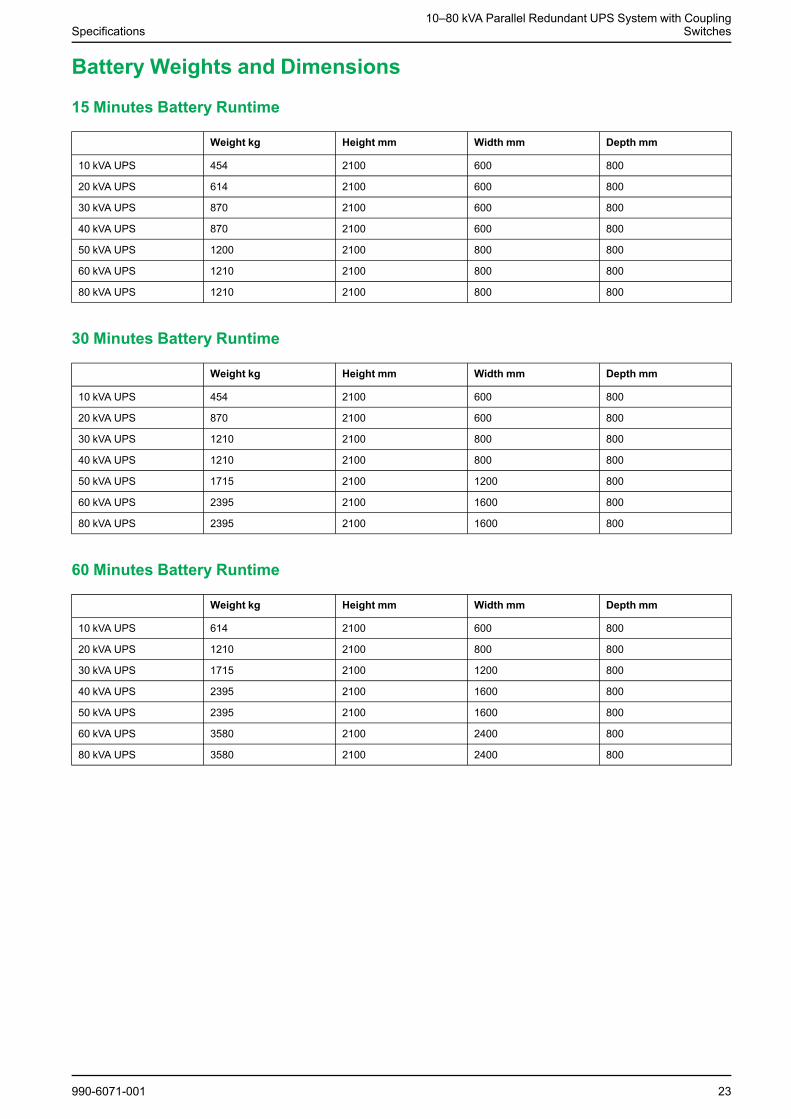
Battery Weights and Dimensions
15 Minutes Battery Runtime
Weight kg Height mm Width mm Depth mm
10 kVA UPS 454 2100 600 800
20 kVA UPS 614 2100 600 800
30 kVA UPS 870 2100 600 800
40 kVA UPS 870 2100 600 800
50 kVA UPS 1200 2100 800 800
60 kVA UPS 1210 2100 800 800
80 kVA UPS 1210 2100 800 800
30 Minutes Battery Runtime
Weight kg Height mm Width mm Depth mm
10 kVA UPS 454 2100 600 800
20 kVA UPS 870 2100 600 800
30 kVA UPS 1210 2100 800 800
40 kVA UPS 1210 2100 800 800
50 kVA UPS 1715 2100 1200 800
60 kVA UPS 2395 2100 1600 800
80 kVA UPS 2395 2100 1600 800
60 Minutes Battery Runtime
Weight kg Height mm Width mm Depth mm
10 kVA UPS 614 2100 600 800
20 kVA UPS 1210 2100 800 800
30 kVA UPS 1715 2100 1200 800
40 kVA UPS 2395 2100 1600 800
50 kVA UPS 2395 2100 1600 800
60 kVA UPS 3580 2100 2400 800
80 kVA UPS 3580 2100 2400 800
990-6071-001 23
10–80 kVA Parallel Redundant UPS System with CouplingSwitches Specifications
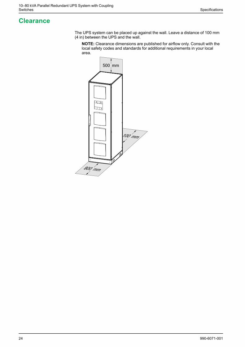
ClearanceThe UPS system can be placed up against the wall. Leave a distance of 100 mm(4 in) between the UPS and the wall.
NOTE: Clearance dimensions are published for airflow only. Consult with thelocal safety codes and standards for additional requirements in your localarea.
24 990-6071-001
System Overview10–80 kVA Parallel Redundant UPS System with Coupling
Switches
System Overview
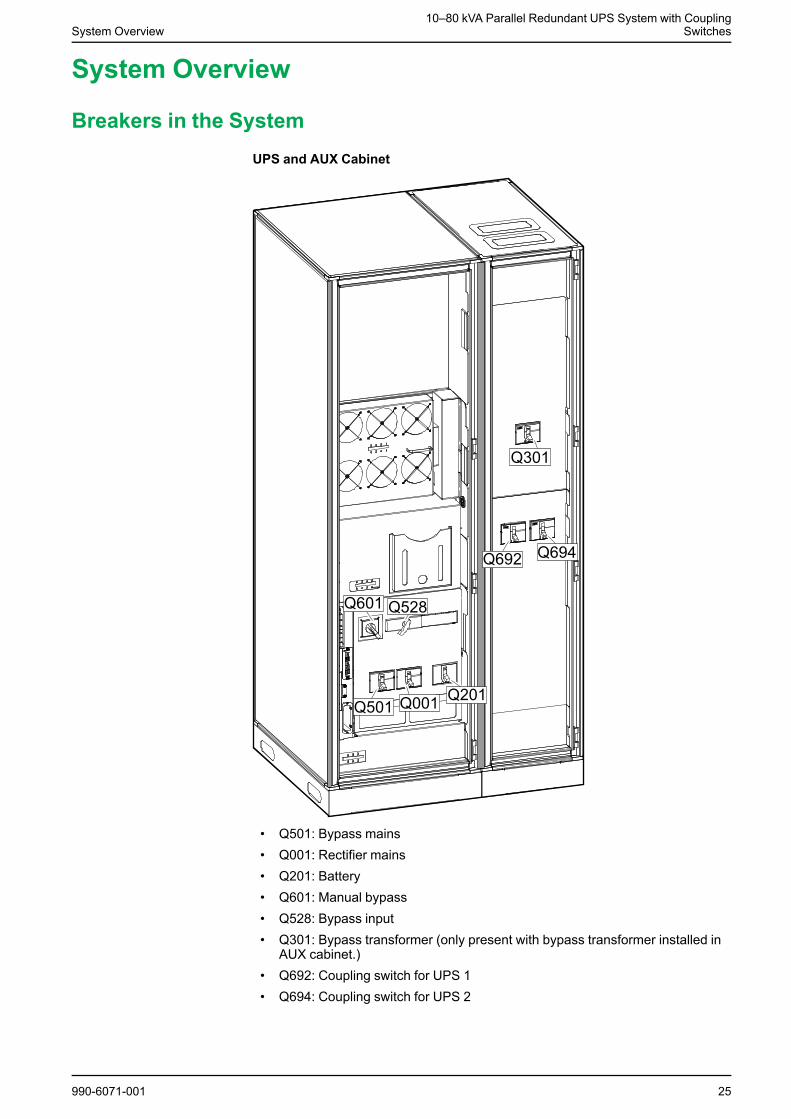
Breakers in the SystemUPS and AUX Cabinet
• Q501: Bypass mains• Q001: Rectifier mains• Q201: Battery• Q601: Manual bypass• Q528: Bypass input• Q301: Bypass transformer (only present with bypass transformer installed in
AUX cabinet.)• Q692: Coupling switch for UPS 1• Q694: Coupling switch for UPS 2
990-6071-001 25
10–80 kVA Parallel Redundant UPS System with CouplingSwitches System Overview
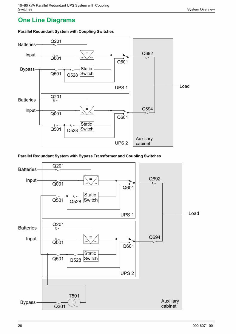
One Line DiagramsParallel Redundant System with Coupling Switches
Parallel Redundant System with Bypass Transformer and Coupling Switches
26 990-6071-001
Installation Procedure for Bottom Cable Entry System10–80 kVA Parallel Redundant UPS System with Coupling
Switches
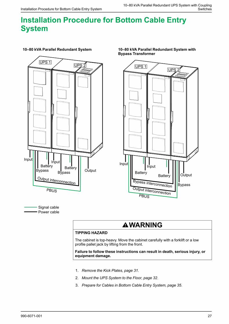
Installation Procedure for Bottom Cable EntrySystem
10–80 kVA Parallel Redundant System 10–80 kVA Parallel Redundant System withBypass Transformer
WARNINGTIPPING HAZARD
The cabinet is top-heavy. Move the cabinet carefully with a forklift or a lowprofile pallet jack by lifting from the front.
Failure to follow these instructions can result in death, serious injury, orequipment damage.
1. Remove the Kick Plates, page 31.
2. Mount the UPS System to the Floor, page 32.
3. Prepare for Cables in Bottom Cable Entry System, page 35.
990-6071-001 27

10–80 kVA Parallel Redundant UPS System with CouplingSwitches Installation Procedure for Bottom Cable Entry System
4. Follow one of the procedures:
– Connect the Power Cables on the 10-40 kVA Parallel Redundant Systemwith Bottom Cable Entry, page 38, or
– Connect the Power Cables on the 50–80 kVA Parallel Redundant Systemwith Bottom Cable Entry, page 40, or
– Connect the Power Cables on the 50-80 kVA Parallel Redundant Systemwith Bottom Cable Entry and Bypass Transformer, page 44, or
– Connect the Power Cables on the 10-40 kVA Parallel Redundant Systemwith Bottom Cable Entry and Bypass Transformer, page 42.
5. Connect the Signal Cables, page 52.
6. Connect the Signal Cables for the Coupling Switches in Parallel RedundantBottom Cable Entry System, page 56.
7. Reinstall the Kick Plates, page 58.
28 990-6071-001
Installation Procedure for Top Cable Entry System10–80 kVA Parallel Redundant UPS System with Coupling
Switches
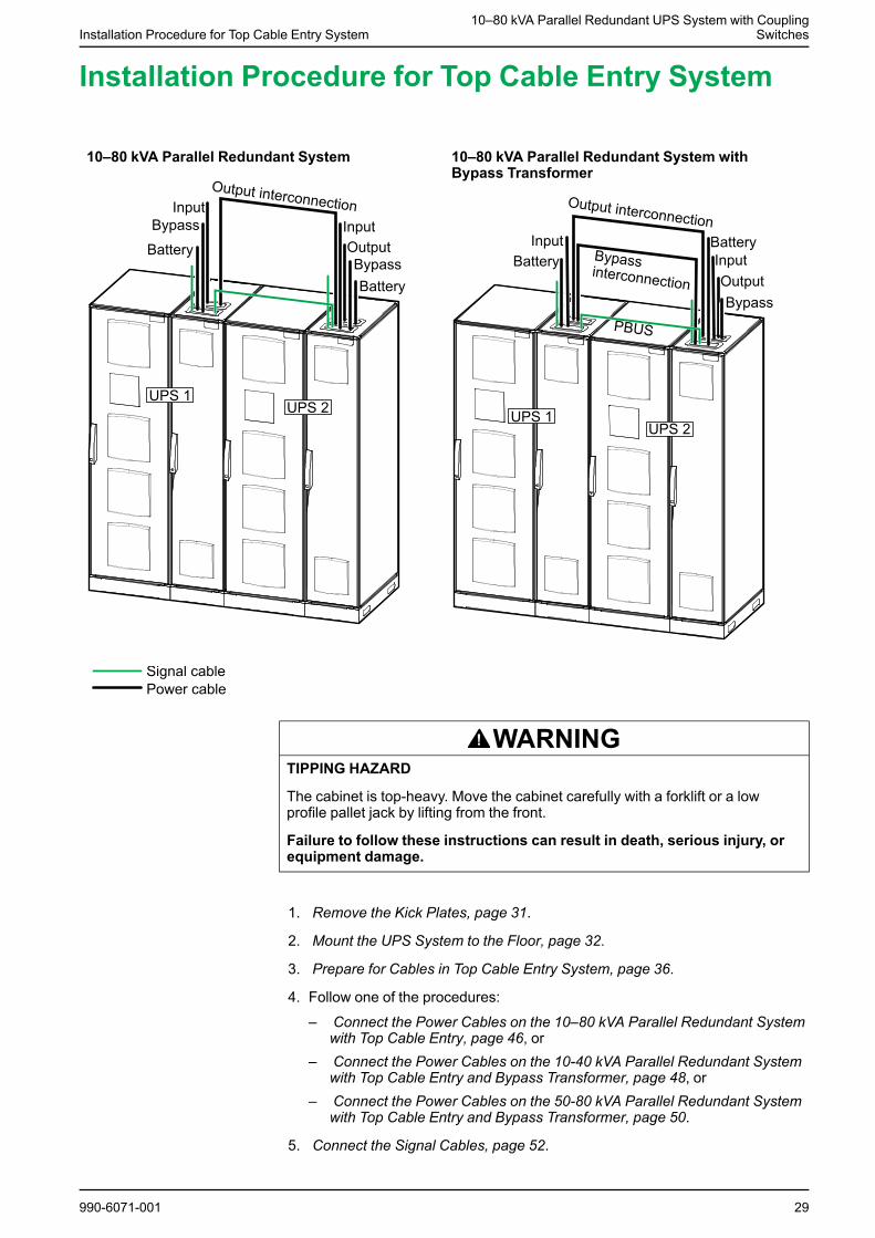
Installation Procedure for Top Cable Entry System
10–80 kVA Parallel Redundant System 10–80 kVA Parallel Redundant System withBypass Transformer
WARNINGTIPPING HAZARD
The cabinet is top-heavy. Move the cabinet carefully with a forklift or a lowprofile pallet jack by lifting from the front.
Failure to follow these instructions can result in death, serious injury, orequipment damage.
1. Remove the Kick Plates, page 31.
2. Mount the UPS System to the Floor, page 32.
3. Prepare for Cables in Top Cable Entry System, page 36.
4. Follow one of the procedures:
– Connect the Power Cables on the 10–80 kVA Parallel Redundant Systemwith Top Cable Entry, page 46, or
– Connect the Power Cables on the 10-40 kVA Parallel Redundant Systemwith Top Cable Entry and Bypass Transformer, page 48, or
– Connect the Power Cables on the 50-80 kVA Parallel Redundant Systemwith Top Cable Entry and Bypass Transformer, page 50.
5. Connect the Signal Cables, page 52.
990-6071-001 29

10–80 kVA Parallel Redundant UPS System with CouplingSwitches Installation Procedure for Top Cable Entry System
6. Connect the Signal Cables for the Coupling Switches in Parallel RedundantTop Cable Entry System, page 57.
7. Reinstall the Kick Plates, page 58.
30 990-6071-001
Remove the Kick Plates10–80 kVA Parallel Redundant UPS System with Coupling
Switches
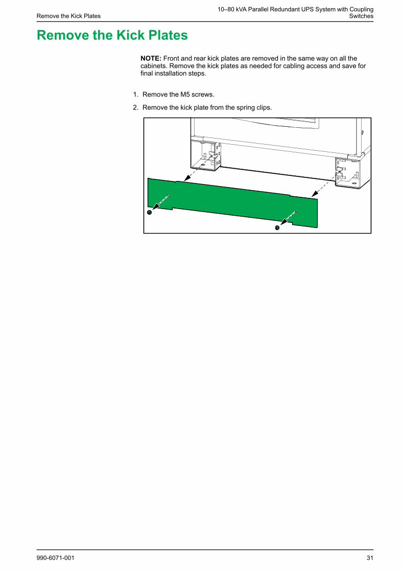
Remove the Kick PlatesNOTE: Front and rear kick plates are removed in the same way on all thecabinets. Remove the kick plates as needed for cabling access and save forfinal installation steps.
1. Remove the M5 screws.
2. Remove the kick plate from the spring clips.
990-6071-001 31
10–80 kVA Parallel Redundant UPS System with CouplingSwitches Mount the UPS System to the Floor
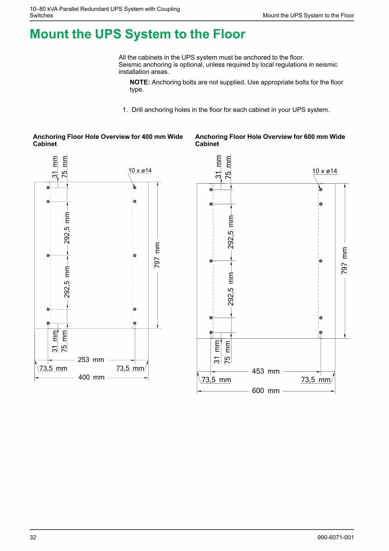
Mount the UPS System to the FloorAll the cabinets in the UPS system must be anchored to the floor.Seismic anchoring is optional, unless required by local regulations in seismicinstallation areas.
NOTE: Anchoring bolts are not supplied. Use appropriate bolts for the floortype.
1. Drill anchoring holes in the floor for each cabinet in your UPS system.
Anchoring Floor Hole Overview for 400 mmWideCabinet
Anchoring Floor Hole Overview for 600 mmWideCabinet
32 990-6071-001
Mount the UPS System to the Floor10–80 kVA Parallel Redundant UPS System with Coupling
Switches
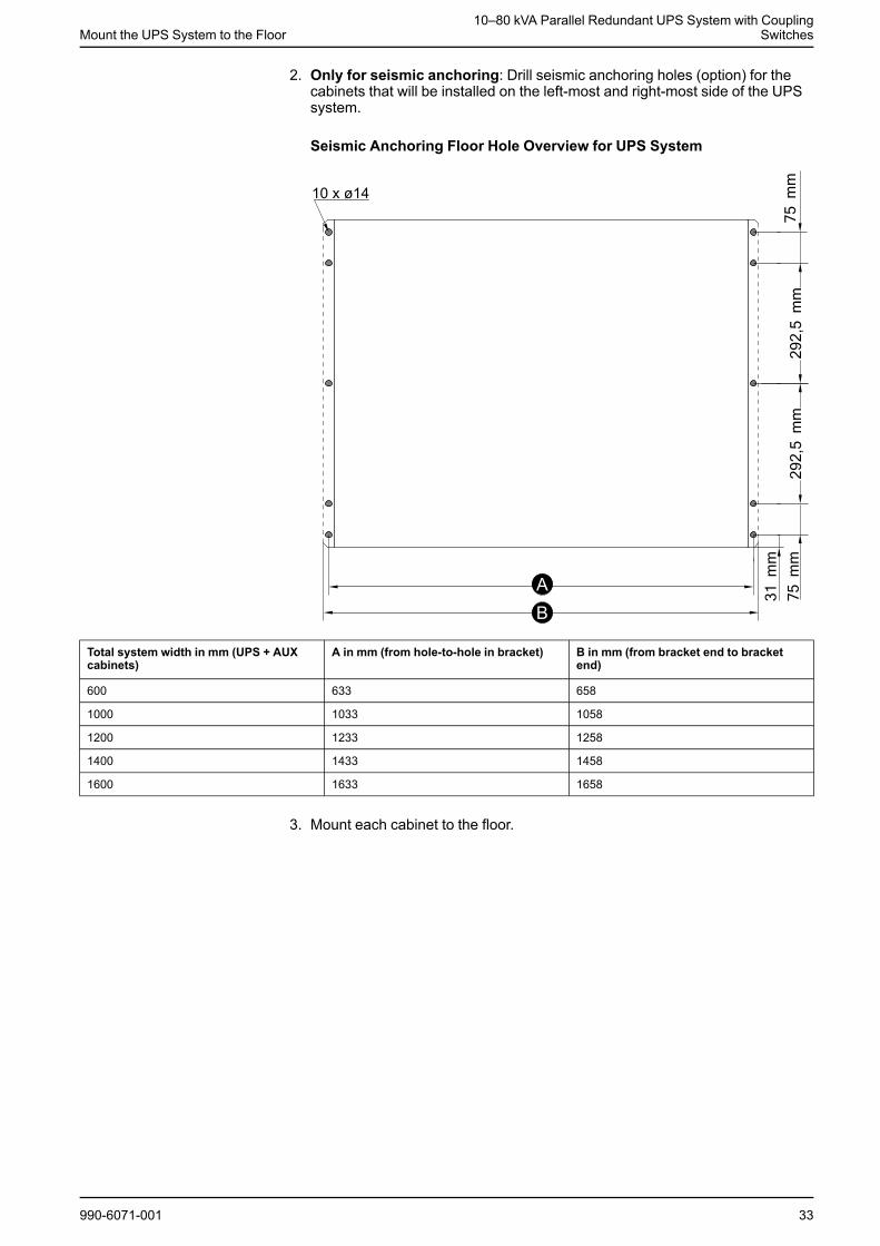
2. Only for seismic anchoring: Drill seismic anchoring holes (option) for thecabinets that will be installed on the left-most and right-most side of the UPSsystem.
Seismic Anchoring Floor Hole Overview for UPS System
Total system width in mm (UPS + AUXcabinets)
A in mm (from hole-to-hole in bracket) B in mm (from bracket end to bracketend)
600 633 658
1000 1033 1058
1200 1233 1258
1400 1433 1458
1600 1633 1658
3. Mount each cabinet to the floor.
990-6071-001 33
10–80 kVA Parallel Redundant UPS System with CouplingSwitches Mount the UPS System to the Floor
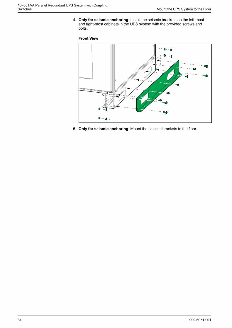
4. Only for seismic anchoring: Install the seismic brackets on the left-mostand right-most cabinets in the UPS system with the provided screws andbolts.
Front View
5. Only for seismic anchoring: Mount the seismic brackets to the floor.
34 990-6071-001
Prepare for Cables in Bottom Cable Entry System10–80 kVA Parallel Redundant UPS System with Coupling
Switches
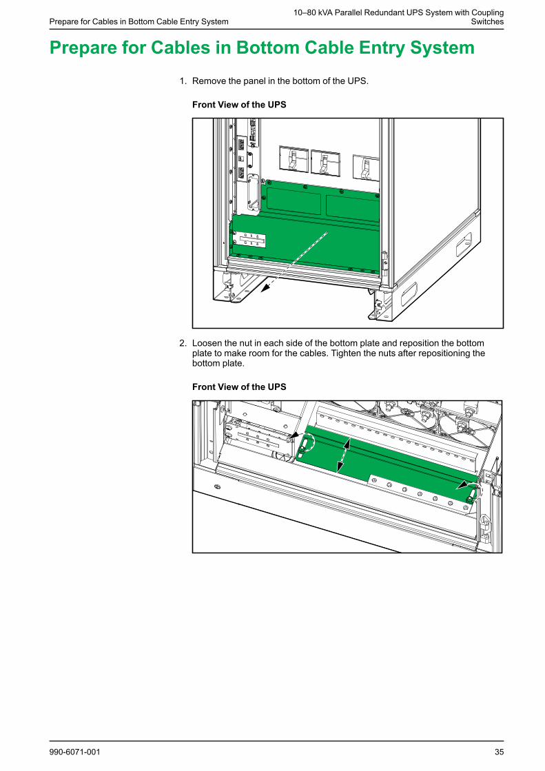
Prepare for Cables in Bottom Cable Entry System1. Remove the panel in the bottom of the UPS.
Front View of the UPS
2. Loosen the nut in each side of the bottom plate and reposition the bottomplate to make room for the cables. Tighten the nuts after repositioning thebottom plate.
Front View of the UPS
990-6071-001 35
10–80 kVA Parallel Redundant UPS System with CouplingSwitches Prepare for Cables in Top Cable Entry System
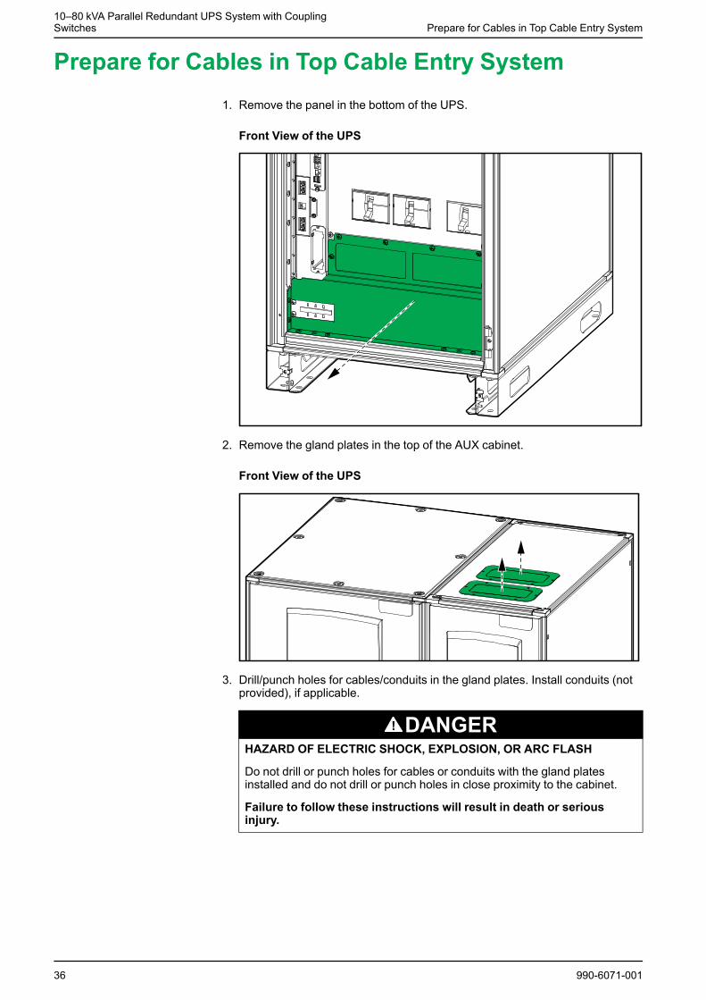
Prepare for Cables in Top Cable Entry System1. Remove the panel in the bottom of the UPS.
Front View of the UPS
2. Remove the gland plates in the top of the AUX cabinet.
Front View of the UPS
3. Drill/punch holes for cables/conduits in the gland plates. Install conduits (notprovided), if applicable.
DANGERHAZARD OF ELECTRIC SHOCK, EXPLOSION, OR ARC FLASH
Do not drill or punch holes for cables or conduits with the gland platesinstalled and do not drill or punch holes in close proximity to the cabinet.
Failure to follow these instructions will result in death or seriousinjury.
36 990-6071-001
Prepare for Cables in Top Cable Entry System10–80 kVA Parallel Redundant UPS System with Coupling
Switches
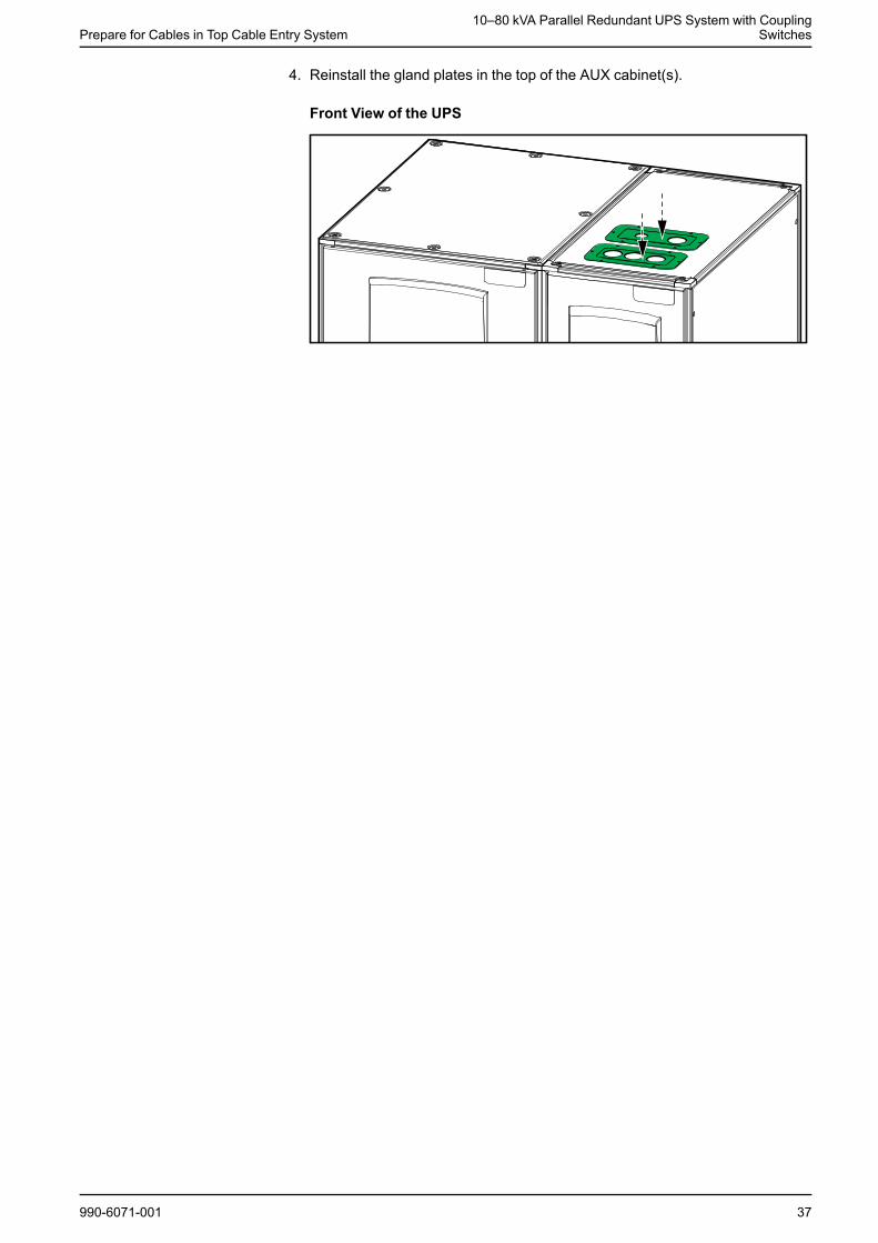
4. Reinstall the gland plates in the top of the AUX cabinet(s).
Front View of the UPS
990-6071-001 37
10–80 kVA Parallel Redundant UPS System with CouplingSwitches
Connect the Power Cables on the 10-40 kVA ParallelRedundant System with Bottom Cable Entry
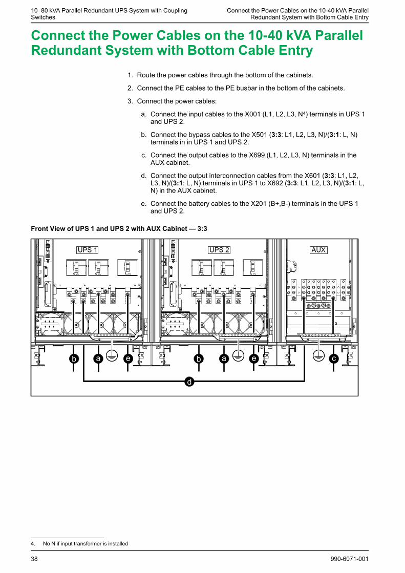
Connect the Power Cables on the 10-40 kVA ParallelRedundant System with Bottom Cable Entry
1. Route the power cables through the bottom of the cabinets.
2. Connect the PE cables to the PE busbar in the bottom of the cabinets.
3. Connect the power cables:
a. Connect the input cables to the X001 (L1, L2, L3, N4) terminals in UPS 1and UPS 2.
b. Connect the bypass cables to the X501 (3:3: L1, L2, L3, N)/(3:1: L, N)terminals in in UPS 1 and UPS 2.
c. Connect the output cables to the X699 (L1, L2, L3, N) terminals in theAUX cabinet.
d. Connect the output interconnection cables from the X601 (3:3: L1, L2,L3, N)/(3:1: L, N) terminals in UPS 1 to X692 (3:3: L1, L2, L3, N)/(3:1: L,N) in the AUX cabinet.
e. Connect the battery cables to the X201 (B+,B-) terminals in the UPS 1and UPS 2.
Front View of UPS 1 and UPS 2 with AUX Cabinet — 3:3
38 990-6071-001
4. No N if input transformer is installed
Connect the Power Cables on the 10-40 kVA ParallelRedundant System with Bottom Cable Entry
10–80 kVA Parallel Redundant UPS System with CouplingSwitches
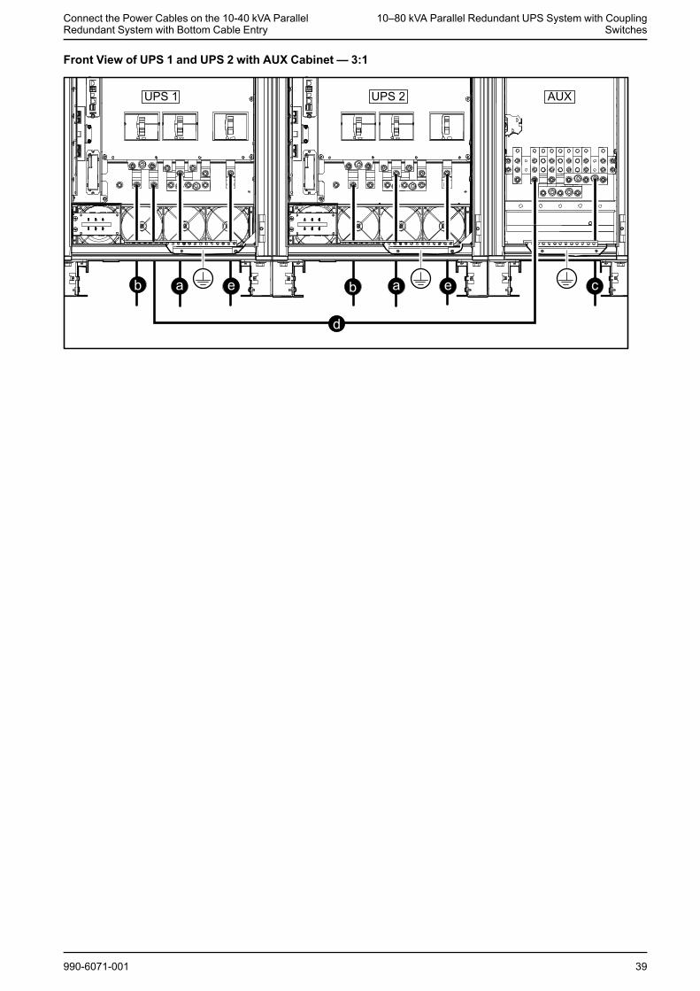
Front View of UPS 1 and UPS 2 with AUX Cabinet — 3:1
990-6071-001 39
10–80 kVA Parallel Redundant UPS System with CouplingSwitches
Connect the Power Cables on the 50–80 kVA ParallelRedundant System with Bottom Cable Entry
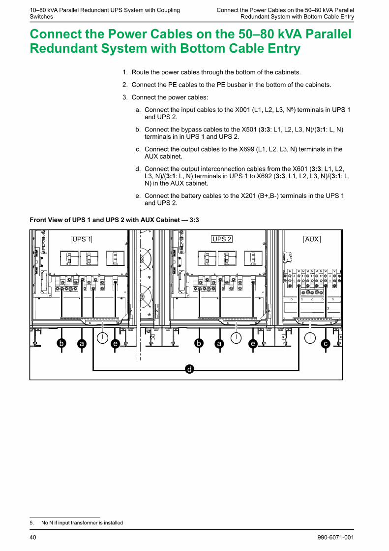
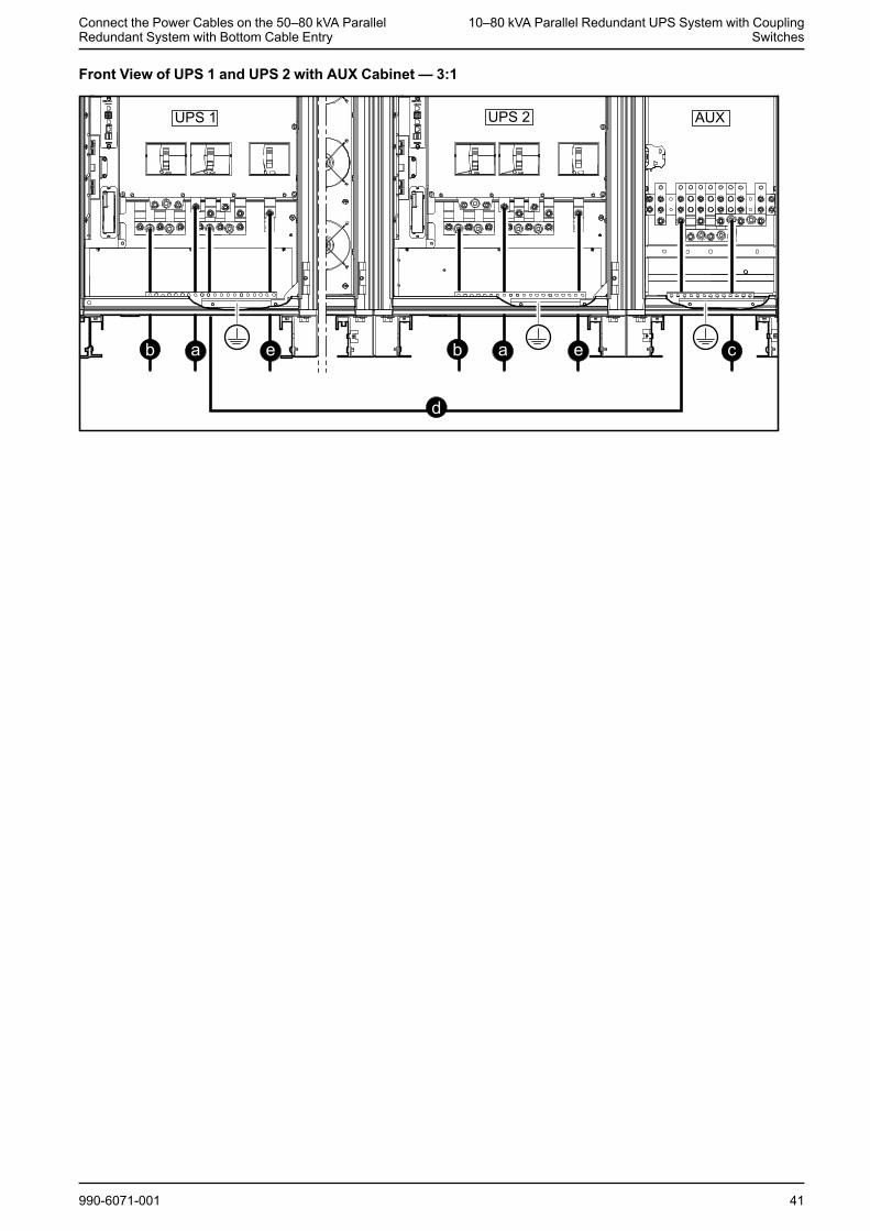
Connect the Power Cables on the 50–80 kVA ParallelRedundant System with Bottom Cable Entry
1. Route the power cables through the bottom of the cabinets.
2. Connect the PE cables to the PE busbar in the bottom of the cabinets.
3. Connect the power cables:
a. Connect the input cables to the X001 (L1, L2, L3, N5) terminals in UPS 1and UPS 2.
b. Connect the bypass cables to the X501 (3:3: L1, L2, L3, N)/(3:1: L, N)terminals in in UPS 1 and UPS 2.
c. Connect the output cables to the X699 (L1, L2, L3, N) terminals in theAUX cabinet.
d. Connect the output interconnection cables from the X601 (3:3: L1, L2,L3, N)/(3:1: L, N) terminals in UPS 1 to X692 (3:3: L1, L2, L3, N)/(3:1: L,N) in the AUX cabinet.
e. Connect the battery cables to the X201 (B+,B-) terminals in the UPS 1and UPS 2.
Front View of UPS 1 and UPS 2 with AUX Cabinet — 3:3
40 990-6071-001
5. No N if input transformer is installed
Connect the Power Cables on the 50–80 kVA ParallelRedundant System with Bottom Cable Entry
10–80 kVA Parallel Redundant UPS System with CouplingSwitches
Front View of UPS 1 and UPS 2 with AUX Cabinet — 3:1
990-6071-001 41
10–80 kVA Parallel Redundant UPS System with CouplingSwitches
Connect the Power Cables on the 10-40 kVA ParallelRedundant System with Bottom Cable Entry and Bypass
Transformer
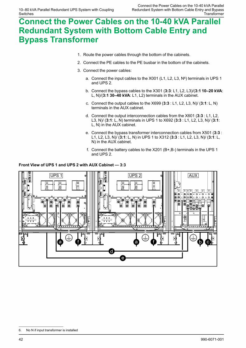
Connect the Power Cables on the 10-40 kVA ParallelRedundant System with Bottom Cable Entry andBypass Transformer
1. Route the power cables through the bottom of the cabinets.
2. Connect the PE cables to the PE busbar in the bottom of the cabinets.
3. Connect the power cables:
a. Connect the input cables to the X001 (L1, L2, L3, N6) terminals in UPS 1and UPS 2.
b. Connect the bypass cables to the X301 (3:3: L1, L2, L3)/(3:1 10–20 kVA:L, N)/(3:1 30–40 kVA: L1, L2) terminals in the AUX cabinet.
c. Connect the output cables to the X699 (3:3 : L1, L2, L3, N)/ (3:1: L, N)terminals in the AUX cabinet.
d. Connect the output interconnection cables from the X601 (3:3 : L1, L2,L3, N)/ (3:1: L, N) terminals in UPS 1 to X692 (3:3 : L1, L2, L3, N)/ (3:1:L, N) in the AUX cabinet.
e. Connect the bypass transformer interconnection cables from X501 (3:3 :L1, L2, L3, N)/ (3:1: L, N) in UPS 1 to X312 (3:3 : L1, L2, L3, N)/ (3:1: L,N) in the AUX cabinet.
f. Connect the battery cables to the X201 (B+,B-) terminals in the UPS 1and UPS 2.
Front View of UPS 1 and UPS 2 with AUX Cabinet — 3:3
42 990-6071-001
6. No N if input transformer is installed
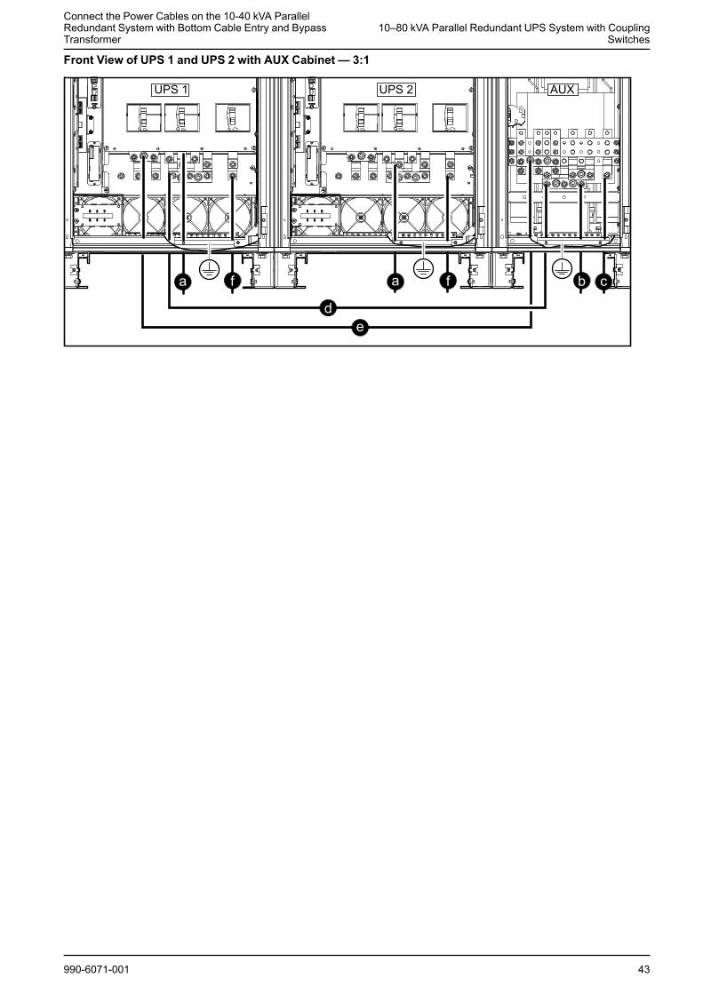
Connect the Power Cables on the 10-40 kVA ParallelRedundant System with Bottom Cable Entry and BypassTransformer
10–80 kVA Parallel Redundant UPS System with CouplingSwitches
Front View of UPS 1 and UPS 2 with AUX Cabinet — 3:1
990-6071-001 43
10–80 kVA Parallel Redundant UPS System with CouplingSwitches
Connect the Power Cables on the 50-80 kVA ParallelRedundant System with Bottom Cable Entry and Bypass
Transformer
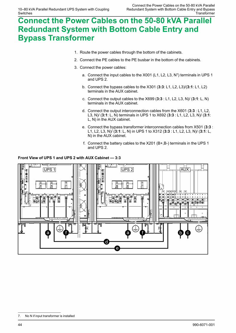
Connect the Power Cables on the 50-80 kVA ParallelRedundant System with Bottom Cable Entry andBypass Transformer
1. Route the power cables through the bottom of the cabinets.
2. Connect the PE cables to the PE busbar in the bottom of the cabinets.
3. Connect the power cables:
a. Connect the input cables to the X001 (L1, L2, L3, N7) terminals in UPS 1and UPS 2.
b. Connect the bypass cables to the X301 (3:3: L1, L2, L3)/(3:1: L1, L2)terminals in the AUX cabinet.
c. Connect the output cables to the X699 (3:3 : L1, L2, L3, N)/ (3:1: L, N)terminals in the AUX cabinet.
d. Connect the output interconnection cables from the X601 (3:3 : L1, L2,L3, N)/ (3:1: L, N) terminals in UPS 1 to X692 (3:3 : L1, L2, L3, N)/ (3:1:L, N) in the AUX cabinet.
e. Connect the bypass transformer interconnection cables from X501 (3:3 :L1, L2, L3, N)/ (3:1: L, N) in UPS 1 to X312 (3:3 : L1, L2, L3, N)/ (3:1: L,N) in the AUX cabinet.
f. Connect the battery cables to the X201 (B+,B-) terminals in the UPS 1and UPS 2.
Front View of UPS 1 and UPS 2 with AUX Cabinet — 3:3
44 990-6071-001
7. No N if input transformer is installed
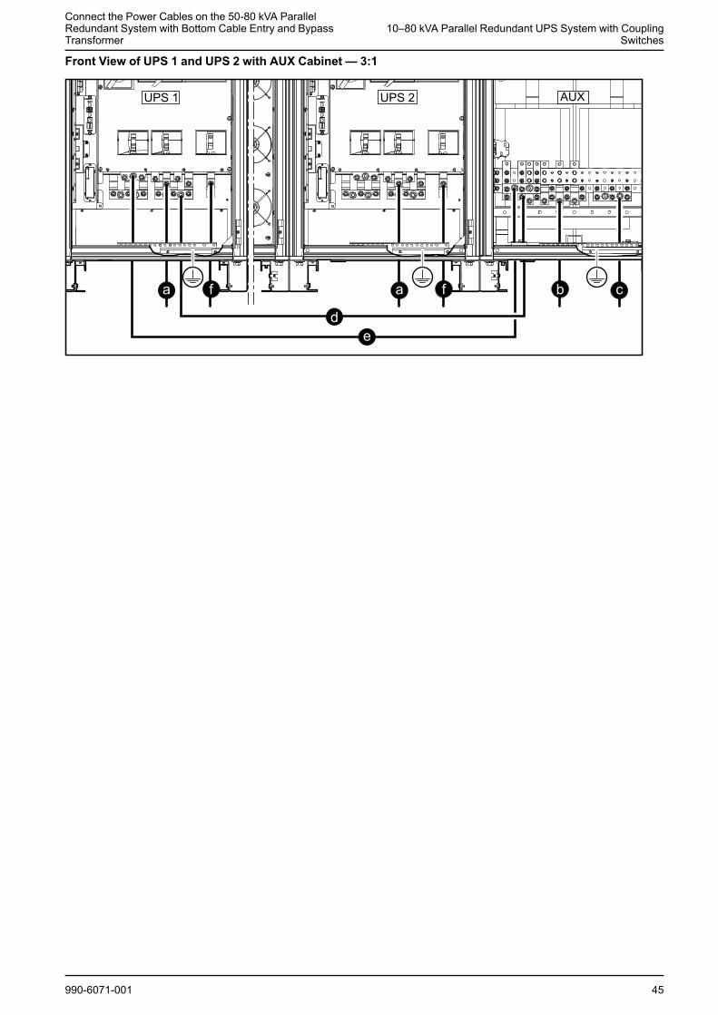
Connect the Power Cables on the 50-80 kVA ParallelRedundant System with Bottom Cable Entry and BypassTransformer
10–80 kVA Parallel Redundant UPS System with CouplingSwitches
Front View of UPS 1 and UPS 2 with AUX Cabinet — 3:1
990-6071-001 45
10–80 kVA Parallel Redundant UPS System with CouplingSwitches
Connect the Power Cables on the 10–80 kVA ParallelRedundant System with Top Cable Entry
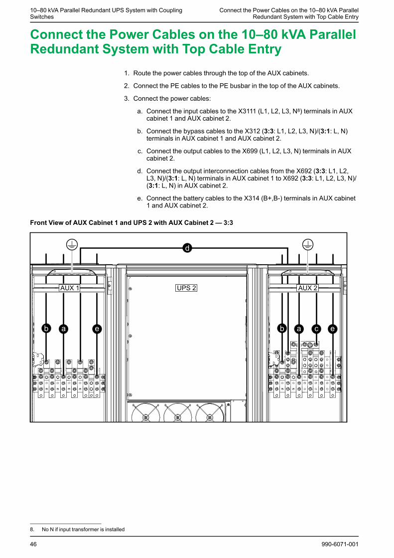
Connect the Power Cables on the 10–80 kVA ParallelRedundant System with Top Cable Entry
1. Route the power cables through the top of the AUX cabinets.
2. Connect the PE cables to the PE busbar in the top of the AUX cabinets.
3. Connect the power cables:
a. Connect the input cables to the X3111 (L1, L2, L3, N8) terminals in AUXcabinet 1 and AUX cabinet 2.
b. Connect the bypass cables to the X312 (3:3: L1, L2, L3, N)/(3:1: L, N)terminals in AUX cabinet 1 and AUX cabinet 2.
c. Connect the output cables to the X699 (L1, L2, L3, N) terminals in AUXcabinet 2.
d. Connect the output interconnection cables from the X692 (3:3: L1, L2,L3, N)/(3:1: L, N) terminals in AUX cabinet 1 to X692 (3:3: L1, L2, L3, N)/(3:1: L, N) in AUX cabinet 2.
e. Connect the battery cables to the X314 (B+,B-) terminals in AUX cabinet1 and AUX cabinet 2.
Front View of AUX Cabinet 1 and UPS 2 with AUX Cabinet 2 — 3:3
46 990-6071-001
8. No N if input transformer is installed
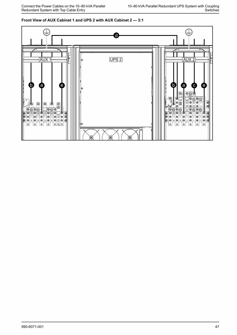
Connect the Power Cables on the 10–80 kVA ParallelRedundant System with Top Cable Entry
10–80 kVA Parallel Redundant UPS System with CouplingSwitches
Front View of AUX Cabinet 1 and UPS 2 with AUX Cabinet 2 — 3:1
990-6071-001 47
10–80 kVA Parallel Redundant UPS System with CouplingSwitches
Connect the Power Cables on the 10-40 kVA ParallelRedundant System with Top Cable Entry and Bypass
Transformer
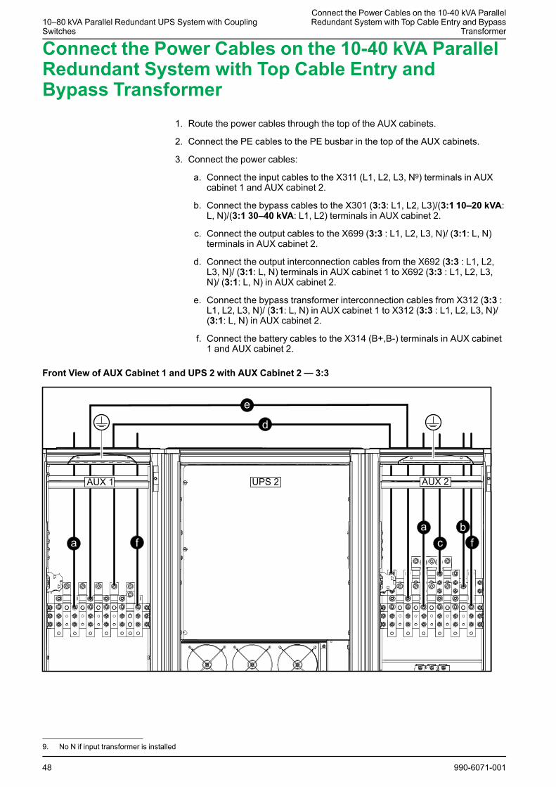
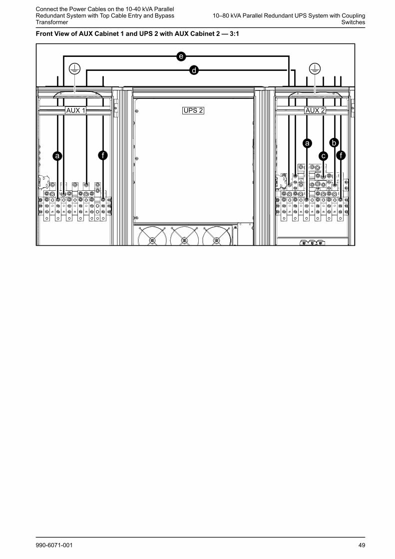
Connect the Power Cables on the 10-40 kVA ParallelRedundant System with Top Cable Entry andBypass Transformer
1. Route the power cables through the top of the AUX cabinets.
2. Connect the PE cables to the PE busbar in the top of the AUX cabinets.
3. Connect the power cables:
a. Connect the input cables to the X311 (L1, L2, L3, N9) terminals in AUXcabinet 1 and AUX cabinet 2.
b. Connect the bypass cables to the X301 (3:3: L1, L2, L3)/(3:1 10–20 kVA:L, N)/(3:1 30–40 kVA: L1, L2) terminals in AUX cabinet 2.
c. Connect the output cables to the X699 (3:3 : L1, L2, L3, N)/ (3:1: L, N)terminals in AUX cabinet 2.
d. Connect the output interconnection cables from the X692 (3:3 : L1, L2,L3, N)/ (3:1: L, N) terminals in AUX cabinet 1 to X692 (3:3 : L1, L2, L3,N)/ (3:1: L, N) in AUX cabinet 2.
e. Connect the bypass transformer interconnection cables from X312 (3:3 :L1, L2, L3, N)/ (3:1: L, N) in AUX cabinet 1 to X312 (3:3 : L1, L2, L3, N)/(3:1: L, N) in AUX cabinet 2.
f. Connect the battery cables to the X314 (B+,B-) terminals in AUX cabinet1 and AUX cabinet 2.
Front View of AUX Cabinet 1 and UPS 2 with AUX Cabinet 2 — 3:3
48 990-6071-001
9. No N if input transformer is installed
Connect the Power Cables on the 10-40 kVA ParallelRedundant System with Top Cable Entry and BypassTransformer
10–80 kVA Parallel Redundant UPS System with CouplingSwitches
Front View of AUX Cabinet 1 and UPS 2 with AUX Cabinet 2 — 3:1
990-6071-001 49
10–80 kVA Parallel Redundant UPS System with CouplingSwitches
Connect the Power Cables on the 50-80 kVA ParallelRedundant System with Top Cable Entry and Bypass
Transformer
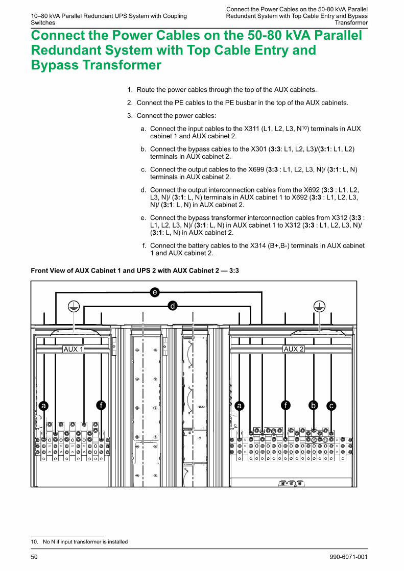
Connect the Power Cables on the 50-80 kVA ParallelRedundant System with Top Cable Entry andBypass Transformer
1. Route the power cables through the top of the AUX cabinets.
2. Connect the PE cables to the PE busbar in the top of the AUX cabinets.
3. Connect the power cables:
a. Connect the input cables to the X311 (L1, L2, L3, N10) terminals in AUXcabinet 1 and AUX cabinet 2.
b. Connect the bypass cables to the X301 (3:3: L1, L2, L3)/(3:1: L1, L2)terminals in AUX cabinet 2.
c. Connect the output cables to the X699 (3:3 : L1, L2, L3, N)/ (3:1: L, N)terminals in AUX cabinet 2.
d. Connect the output interconnection cables from the X692 (3:3 : L1, L2,L3, N)/ (3:1: L, N) terminals in AUX cabinet 1 to X692 (3:3 : L1, L2, L3,N)/ (3:1: L, N) in AUX cabinet 2.
e. Connect the bypass transformer interconnection cables from X312 (3:3 :L1, L2, L3, N)/ (3:1: L, N) in AUX cabinet 1 to X312 (3:3 : L1, L2, L3, N)/(3:1: L, N) in AUX cabinet 2.
f. Connect the battery cables to the X314 (B+,B-) terminals in AUX cabinet1 and AUX cabinet 2.
Front View of AUX Cabinet 1 and UPS 2 with AUX Cabinet 2 — 3:3
50 990-6071-001
10. No N if input transformer is installed
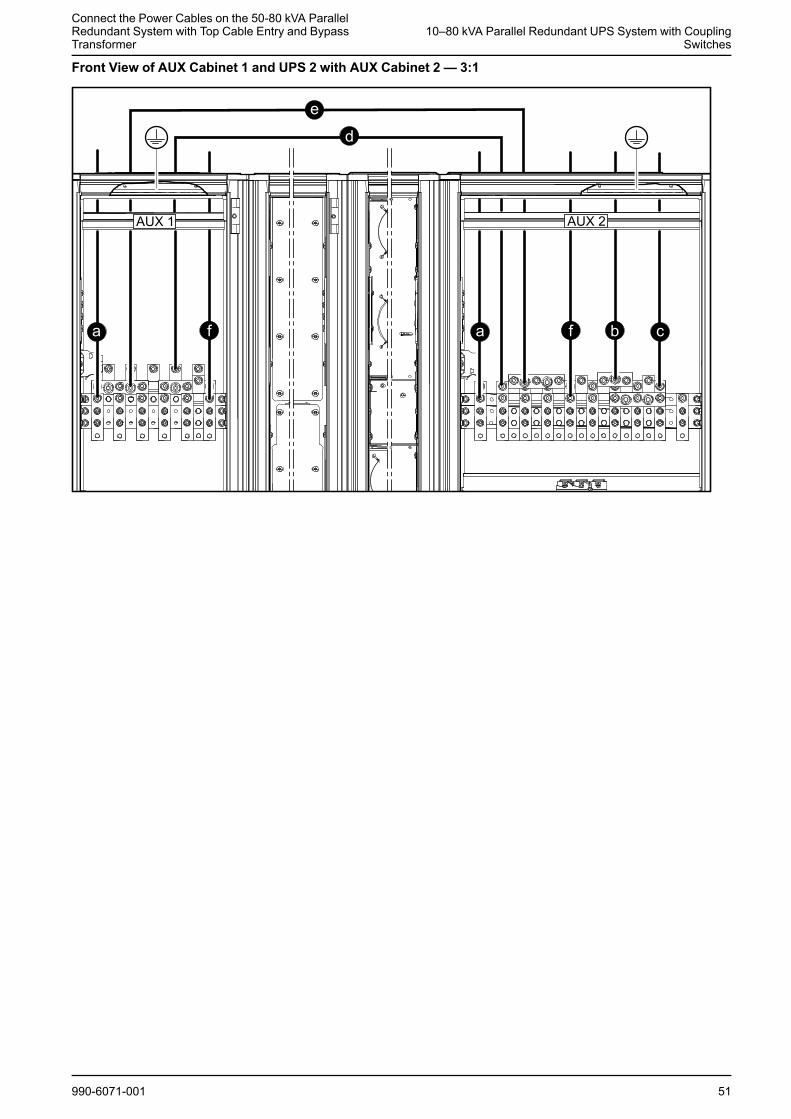
Connect the Power Cables on the 50-80 kVA ParallelRedundant System with Top Cable Entry and BypassTransformer
10–80 kVA Parallel Redundant UPS System with CouplingSwitches
Front View of AUX Cabinet 1 and UPS 2 with AUX Cabinet 2 — 3:1
990-6071-001 51
10–80 kVA Parallel Redundant UPS System with CouplingSwitches Connect the Signal Cables
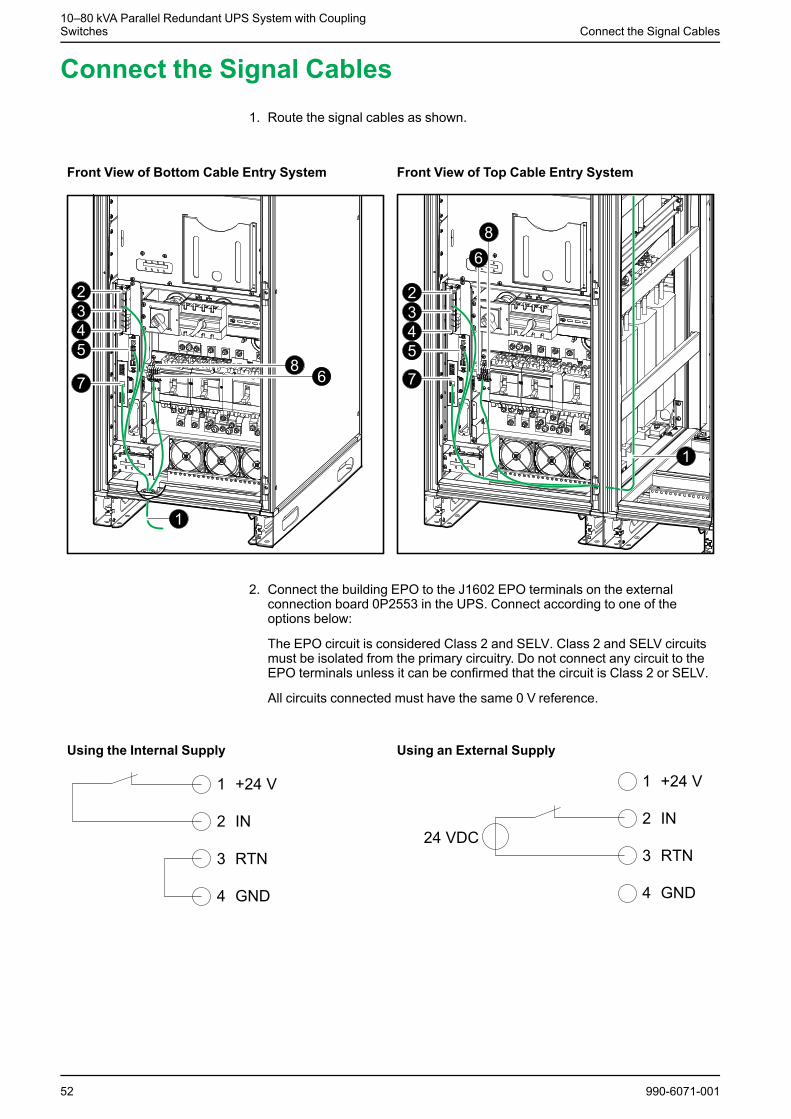
Connect the Signal Cables1. Route the signal cables as shown.
Front View of Bottom Cable Entry System Front View of Top Cable Entry System
2. Connect the building EPO to the J1602 EPO terminals on the externalconnection board 0P2553 in the UPS. Connect according to one of theoptions below:
The EPO circuit is considered Class 2 and SELV. Class 2 and SELV circuitsmust be isolated from the primary circuitry. Do not connect any circuit to theEPO terminals unless it can be confirmed that the circuit is Class 2 or SELV.
All circuits connected must have the same 0 V reference.
Using the Internal Supply Using an External Supply
52 990-6071-001
Connect the Signal Cables10–80 kVA Parallel Redundant UPS System with Coupling
Switches
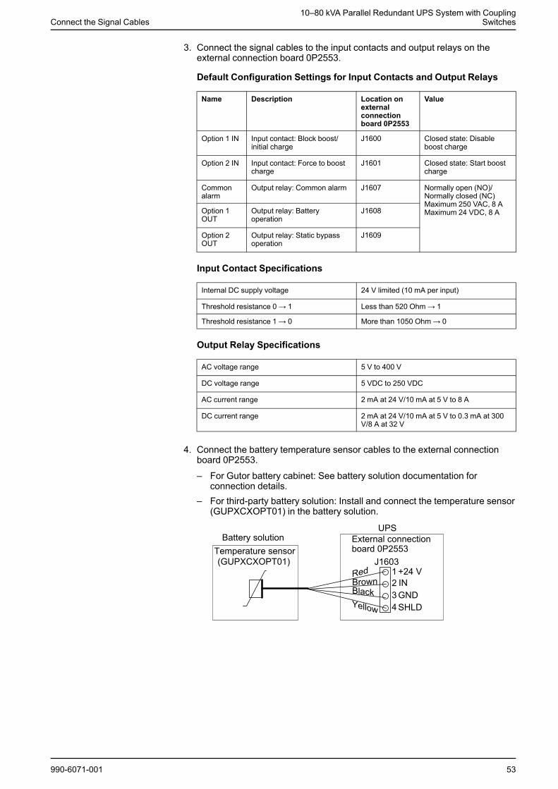
3. Connect the signal cables to the input contacts and output relays on theexternal connection board 0P2553.
Default Configuration Settings for Input Contacts and Output Relays
Name Description Location onexternalconnectionboard 0P2553
Value
Option 1 IN Input contact: Block boost/initial charge
J1600 Closed state: Disableboost charge
Option 2 IN Input contact: Force to boostcharge
J1601 Closed state: Start boostcharge
Commonalarm
Output relay: Common alarm J1607 Normally open (NO)/Normally closed (NC)Maximum 250 VAC, 8 AMaximum 24 VDC, 8 AOption 1
OUTOutput relay: Batteryoperation
J1608
Option 2OUT
Output relay: Static bypassoperation
J1609
Input Contact Specifications
Internal DC supply voltage 24 V limited (10 mA per input)
Threshold resistance 0 → 1 Less than 520 Ohm→ 1
Threshold resistance 1 → 0 More than 1050 Ohm→ 0
Output Relay Specifications
AC voltage range 5 V to 400 V
DC voltage range 5 VDC to 250 VDC
AC current range 2 mA at 24 V/10 mA at 5 V to 8 A
DC current range 2 mA at 24 V/10 mA at 5 V to 0.3 mA at 300V/8 A at 32 V
4. Connect the battery temperature sensor cables to the external connectionboard 0P2553.
– For Gutor battery cabinet: See battery solution documentation forconnection details.
– For third-party battery solution: Install and connect the temperature sensor(GUPXCXOPT01) in the battery solution.
990-6071-001 53
10–80 kVA Parallel Redundant UPS System with CouplingSwitches Connect the Signal Cables
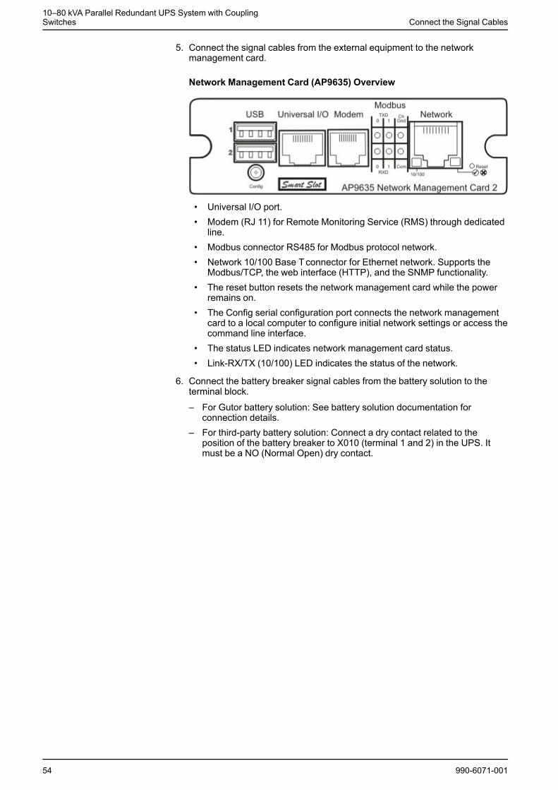
5. Connect the signal cables from the external equipment to the networkmanagement card.
Network Management Card (AP9635) Overview
• Universal I/O port.• Modem (RJ 11) for Remote Monitoring Service (RMS) through dedicated
line.• Modbus connector RS485 for Modbus protocol network.• Network 10/100 Base Tconnector for Ethernet network. Supports the
Modbus/TCP, the web interface (HTTP), and the SNMP functionality.• The reset button resets the network management card while the power
remains on.• The Config serial configuration port connects the network management
card to a local computer to configure initial network settings or access thecommand line interface.
• The status LED indicates network management card status.• Link-RX/TX (10/100) LED indicates the status of the network.
6. Connect the battery breaker signal cables from the battery solution to theterminal block.
– For Gutor battery solution: See battery solution documentation forconnection details.
– For third-party battery solution: Connect a dry contact related to theposition of the battery breaker to X010 (terminal 1 and 2) in the UPS. Itmust be a NO (Normal Open) dry contact.
54 990-6071-001
Connect the Signal Cables10–80 kVA Parallel Redundant UPS System with Coupling
Switches
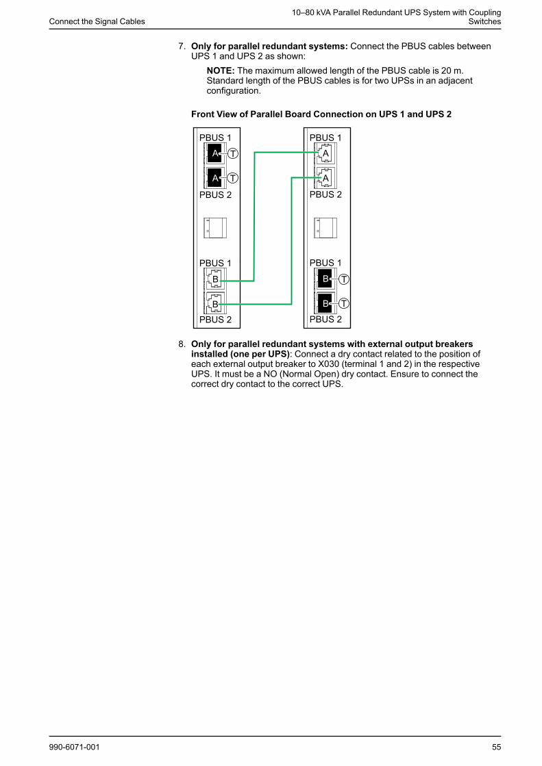
7. Only for parallel redundant systems: Connect the PBUS cables betweenUPS 1 and UPS 2 as shown:
NOTE: The maximum allowed length of the PBUS cable is 20 m.Standard length of the PBUS cables is for two UPSs in an adjacentconfiguration.
Front View of Parallel Board Connection on UPS 1 and UPS 2
8. Only for parallel redundant systems with external output breakersinstalled (one per UPS): Connect a dry contact related to the position ofeach external output breaker to X030 (terminal 1 and 2) in the respectiveUPS. It must be a NO (Normal Open) dry contact. Ensure to connect thecorrect dry contact to the correct UPS.
990-6071-001 55
10–80 kVA Parallel Redundant UPS System with CouplingSwitches Connect the Signal Cables
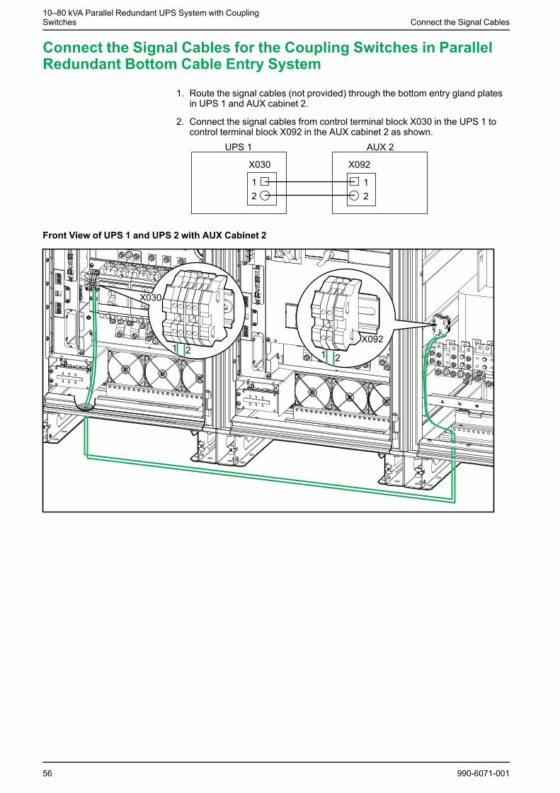
Connect the Signal Cables for the Coupling Switches in ParallelRedundant Bottom Cable Entry System
1. Route the signal cables (not provided) through the bottom entry gland platesin UPS 1 and AUX cabinet 2.
2. Connect the signal cables from control terminal block X030 in the UPS 1 tocontrol terminal block X092 in the AUX cabinet 2 as shown.
Front View of UPS 1 and UPS 2 with AUX Cabinet 2
56 990-6071-001
Connect the Signal Cables10–80 kVA Parallel Redundant UPS System with Coupling
Switches
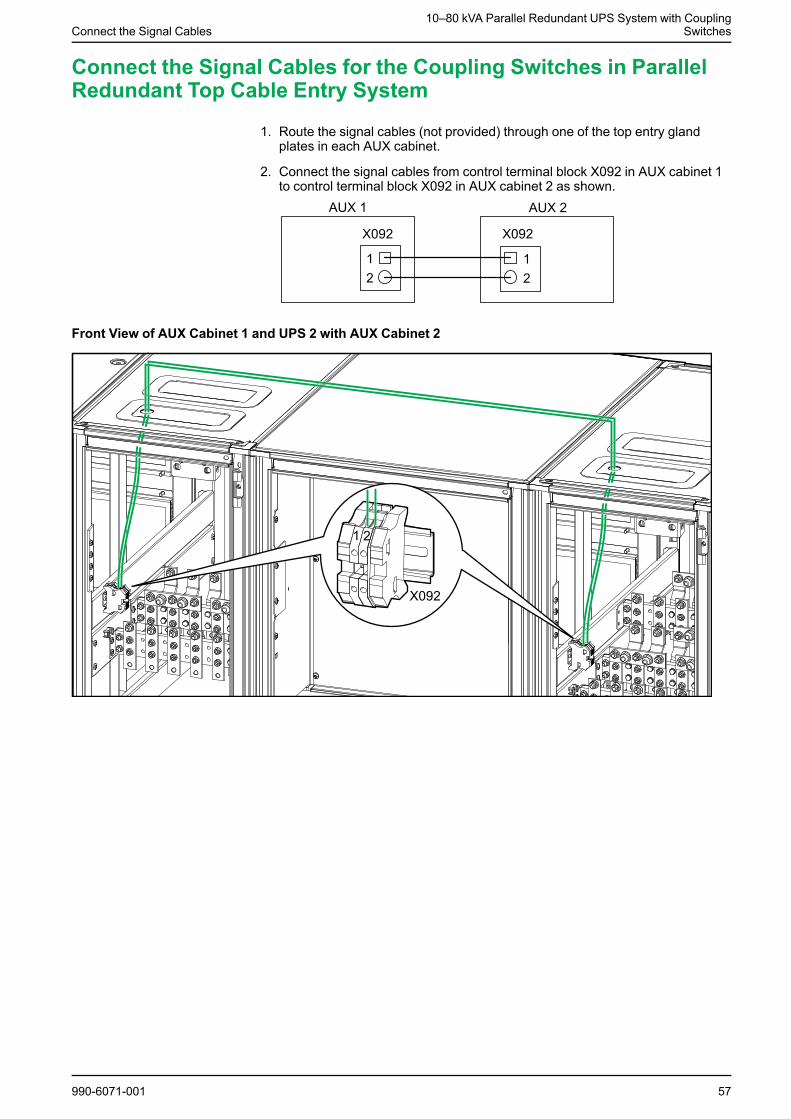
Connect the Signal Cables for the Coupling Switches in ParallelRedundant Top Cable Entry System
1. Route the signal cables (not provided) through one of the top entry glandplates in each AUX cabinet.
2. Connect the signal cables from control terminal block X092 in AUX cabinet 1to control terminal block X092 in AUX cabinet 2 as shown.
Front View of AUX Cabinet 1 and UPS 2 with AUX Cabinet 2
990-6071-001 57
10–80 kVA Parallel Redundant UPS System with CouplingSwitches Reinstall the Kick Plates
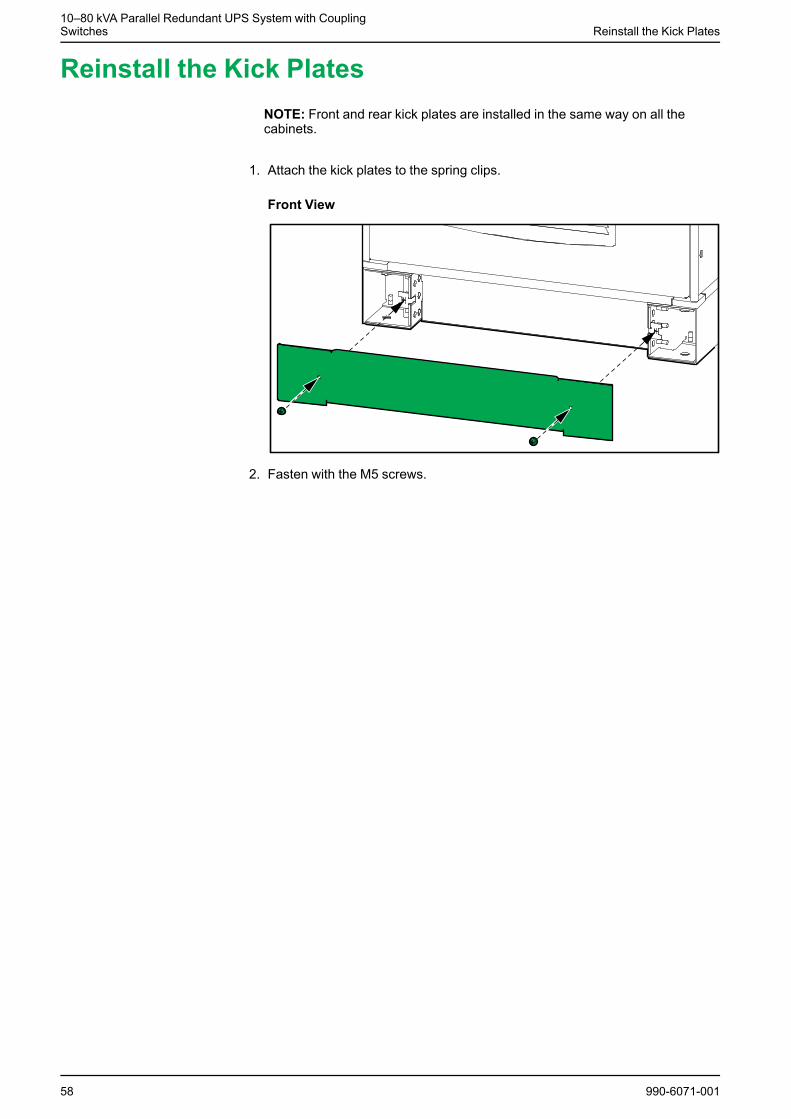
Reinstall the Kick PlatesNOTE: Front and rear kick plates are installed in the same way on all thecabinets.
1. Attach the kick plates to the spring clips.
Front View
2. Fasten with the M5 screws.
58 990-6071-001


Schneider Electric35 rue Joseph Monier92500 Rueil MalmaisonFrance
+ 33 (0) 1 41 29 70 00
*990-6071-001*As standards, specifications, and design change from time to time,please ask for confirmation of the information given in this publication.
© 2018 – 2018 Schneider Electric. All rights reserved.
990-6071-001