Embed Size (px)
Citation preview

© S
EP
TU
A/T
TP
S -
1 -
2004-0
4--
28 -
RE
L 5
71 1
.0.p
pt
RED 670Line Differential
Protection Terminal
Gustavo [email protected]
ABB Substation Automation Systems
Brazil
www.abb.com/substationautomation

Bertil Lundqvist 2005-09-07, slide 2
Features: RED670
Line differential terminal for:
All voltage levels
OH-lines
Cables
Double circuit lines
Series compensated lines
Single and two pole tripping
Optional protection functions
Digital communication between line ends
Route switched communication networks
Easy upgrading from 2 terminal to tapped line protection

Bertil Lundqvist 2005-09-07, slide 3
Line Differential Protection: RED670
Application Areas
Multi-terminal lines with communication to 4 remote line ends
Multi-terminal lines with transformers in the protected zone
Tapped lines
Tapped lines with transformers
Short lines
Long lines with charging current compensation
Bertil Lundqvist 2005-09-07, slide 4
PS
M
Remote communication module with 4 ports
Digital communication channels, 64 kbit/s, are required
Possibility for redundant channels (for 2 to 3 terminals)
Fibre optical module for dedicated fibres
C37.94 optical module
External G.703 converter (optical/electrical)
Two local analogue inputs for differential protection
Additional local inputs for complementary protection
Hardware Structure
CB3
CB2
CB1
No external summation
NU
M
IOM
BO
M PS
M
TR
M1
GS
M
AD
1
BIM
MIM
BIM
Bertil Lundqvist 2005-09-07, slide 5
> <
RED670
><
RED
670
External
Modem
21-216
PCM><
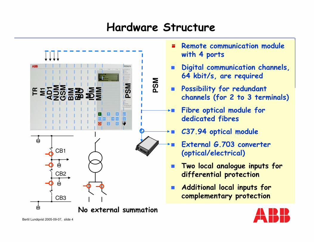
Optical/galvanic modem C37.94 protocol from RED 670G703 64 kbit or G703E1 2 Mbit from modem to PCM
< 10 m
Back-to-backC37.94 protocol
G703
Optical fibres
Three Communication Alternatives
RED
670PCM>
< C37.94 protocol from RED 670
Route switched systemsPCM with C37.94 interface
RED670
Optical fibres
Optical fibres
Bertil Lundqvist 2005-09-07, slide 6
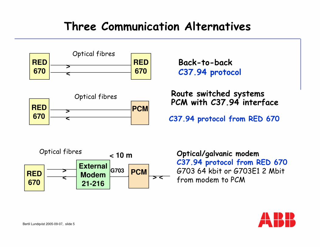
Route switched systems with REL 551/561
Tolerates different routes in forwardand reverse direction only during switching
< 0,2-0,5 ms difference continuous*
Maximum transmission time∆T < 15 ms
B
A C
*Depending on required sensitivity
EC
REL551/561
EC
REL551/561

Bertil Lundqvist 2005-09-07, slide 7
GPS system required for set up
GPS loss tolerated with:
Free-wheeling internal clocks
Fall back to the echo method
Maximum transmission timeTd < 40 ms
GPSclock
D
B
A C
GPSclock
GPSclock
GPSclock
Route switched systems with RED 670
Tolerates unspecified route
switching in telecommunication
systems (SDH/PDH)

Bertil Lundqvist 2005-09-07, slide 8
Excellent tripping time <25 ms
Completely phase segregated measurement
Extremely stable for external faults
Very good sensitivity for internal faults
Flexible communication configuration - back-to back systems
- route switched systems with fixed transmission time in both directions using echo-synchronisation
- telecommunication (SDH) systems with undefined route-switching using GPS synchronisation
Multifunction configuration
Main features for the differential protection

Bertil Lundqvist 2005-09-07, slide 9
Low CT requirements,
Allowed CT ratio difference < 30:1
Differential algorithm not dependent on the number of connected lines
Dual slope stabilisation
Minimum operate current 10-150%
Transfer trip can be sent to all terminals
Main features

Bertil Lundqvist 2005-09-07, slide 10
bias
Idiff
Normal condition
ΙΙΙΙ
Imin
Dual slope stabilisation
Bertil Lundqvist 2005-09-07, slide 11
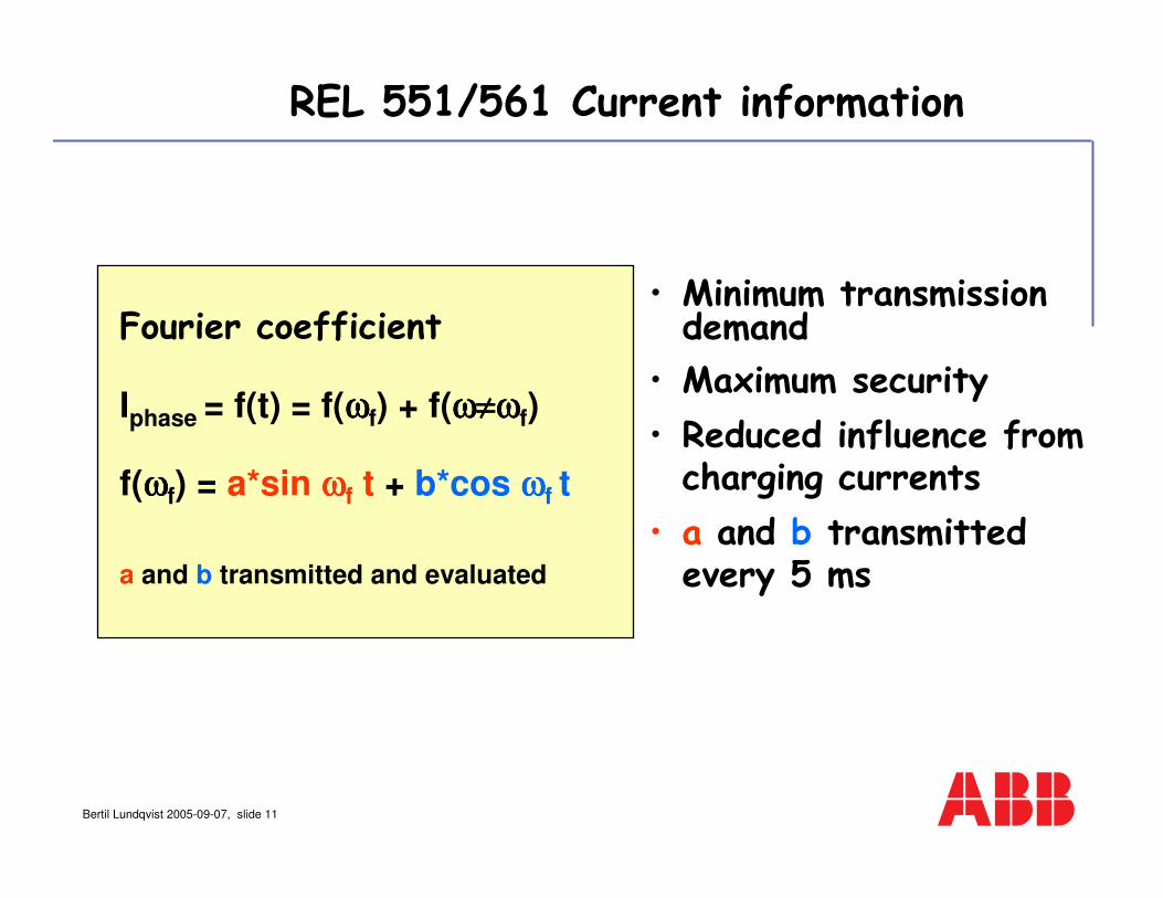
Fourier coefficient
Iphase = f(t) = f(ωωωωf) + f(ω≠ωω≠ωω≠ωω≠ωf)
f(ωωωωf) = a*sin ωωωωf t + b*cos ωωωωf t
a and b transmitted and evaluated
• Minimum transmission demand
• Maximum security
• Reduced influence from charging currents
• a and b transmitted every 5 ms
REL 551/561 Current information

Bertil Lundqvist 2005-09-07, slide 12
Evaluation every 5 ms
Trip at 2 or 3 “trip”evaluations out of 4 evaluations
a and b are transmitted together with check bits
”Moving
Window”
2/3 of 45 ms
T T 00 0 0 0 T 0 0 0 0 0
REL 551/561Trip Evaluation Logic
Bertil Lundqvist 2005-09-07, slide 13
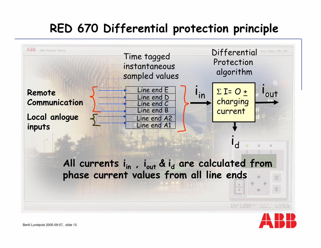
RED 670 Differential protection principle
Time taggedinstantaneoussampled values
Remote Communication
Local anlogueinputs
All currents iin , iout & id are calculated from phase current values from all line ends
DifferentialProtection algorithm
ioutiin
id
Line end A2Line end A1
Line end BLine end CLine end DLine end E Σ I= O +
charging current

Bertil Lundqvist 2005-09-07, slide 14
Time taggedinstantaneoussampled phase currents values
RED 670 Differential protection principle
Symmetricalcomponents
Fourierfilter
Remote Communication
Local anlogueinputs
Transformer inrush blocking- second harmonic- wave block- 5 th harmonic
Transformerinterturn fault-negative sequence2-20% of I base
Currentdifferential
BlockTripBlock
StartTrip
onoff

Bertil Lundqvist 2005-09-07, slide 15
Sampled values collected every 1 ms
Communication message sent every 5 ms
Each communication message contains 5 sets of sampled values
RED 670 Differential Trip Security
5 ms
0 T 00 0 0 0 0 0 T 0 0 0
Trip enabled with 5 consecutive sample sets calculated to trip
1 or 2 messages required depending on fault incidence point
12345
12
345
Bertil Lundqvist 2005-09-07, slide 16
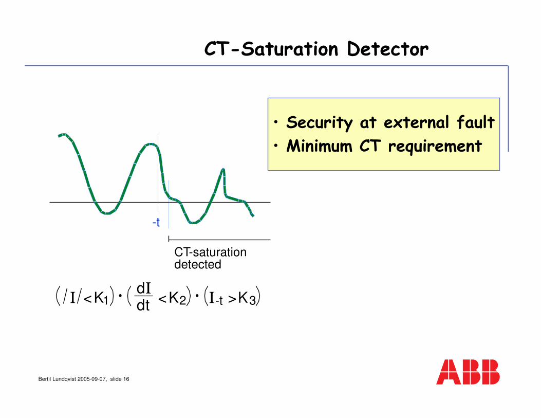
CT-Saturation Detector
CT-saturationdetected
Ι <K1dΙ
dt<K2 Ι-t >K3
-t
• Security at external fault
• Minimum CT requirement
Bertil Lundqvist 2005-09-07, slide 17
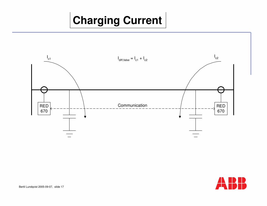
Charging Current
RED
670
RED
670
Communication
Ic1
Ic2I
diff,false = I
c1 + I
c2

Bertil Lundqvist 2005-09-07, slide 18
Charging Current Compensation
Continuous estimation of differential current at no-fault condition: Charging current
Pre-fault charging current estimation kept during faults
Subtraction of the false pre-fault differential currents
At low resistance faults the fault current is large: dominating over the charging current: Error in the charging current compensation has minor influence
At high resistive faults the voltage is maintained and the charging current is close to the non-faulted case

Bertil Lundqvist 2005-09-07, slide 19
Power transformers can be applied within the protected zone
Small power transformers without a line differential terminal
Time delayed differential function gives selective tripping for secondary side faults
Instantaneous differential function for faults on the line
Id> Id >
Id >
Id> Id >
Application examples

Bertil Lundqvist 2005-09-07, slide 20
CB 1Line 1 Line 2
CB 2
D
2-winding power transformer with connected small delta tertiary load. Two lines (cables).
Application examples tapped lines
CB 1Line 1
Line 2
CB 2
Passive load
2-winding power transformer on tapped line. Two lines (cables).
Two terminal applications

Bertil Lundqvist 2005-09-07, slide 21
Line 1CB 1 Line 3
CB 3
Line 2
CB 2
Line 4CB 3
Line 3
CB 2
Line 1
CB 1
Line 2
CB 2
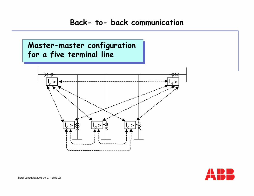
Three terminal application.3-winding power transformer with small delta tertiary. Three lines (cables).
Four terminal application.2-winding power transformer, small delta tertiary. Four lines (cables).
D
D
Application examples multicircuit lines
Bertil Lundqvist 2005-09-07, slide 22
Id >
Id > I
d > I
d >
Id >
Master-master configurationfor a five terminal line
Back- to- back communication
Bertil Lundqvist 2005-09-07, slide 23
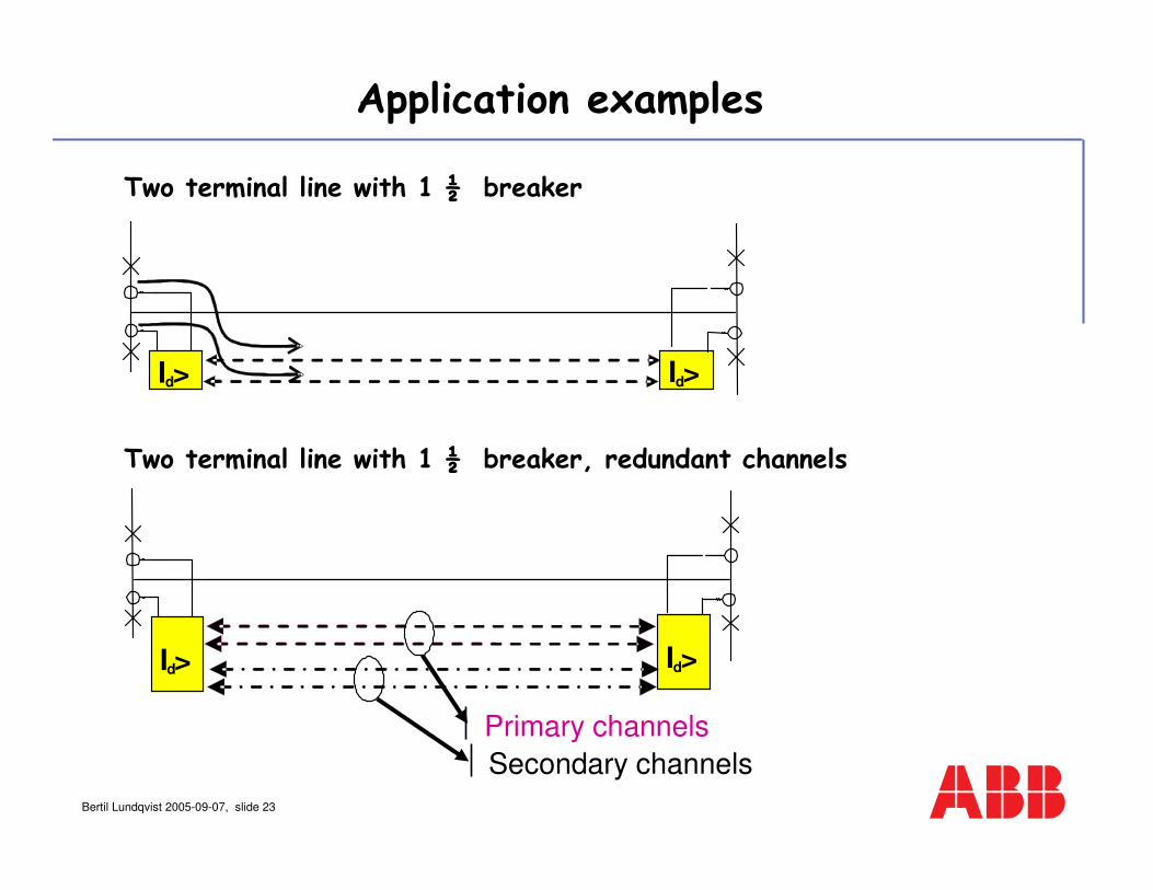
Id> Id>
Two terminal line with 1 ½ breaker
Two terminal line with 1 ½ breaker, redundant channels
Id>
Primary channels
Secondary channels
Id>
Application examples

Bertil Lundqvist 2005-09-07, slide 24
Id
>
Id
>
Id
>
Three terminal line with 1 ½ breaker
Application examples

Bertil Lundqvist 2005-09-07, slide 25
The Protected Circuit (Sydkratft’s 130 kV system)
CB 5
Sege, CurrentTerminal 1
Stjarneholm,
Current Terminal 5
CB 3
Fault:L1 - E
Rf = 50 Ω
CB 2 CB 4
Arrie, Current Terminal 2Svedala,
Current Terminal 4
3000/2 A
1500/2 A
CB 1
1000/2 A Trelleborg, Current Terminal 3
1200/2 A
12.9 km
4.8 km
15.5 km
22.0 km
2.9 km
1000/2 A
3.9 km
5-terminal application in Sweden
Bertil Lundqvist 2005-09-07, slide 26
B
H
BR
0 t
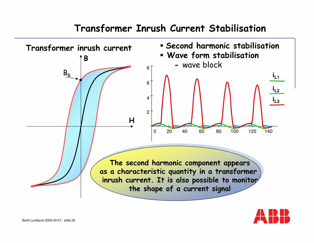
The second harmonic component appearsas a characteristic quantity in a transformer inrush current. It is also possible to monitor
the shape of a current signal
Second harmonic stabilisation Wave form stabilisation
- wave block
0 20 40 60 80 100 120 140
2
4
6
8
iL1
iL2
iL3
Transformer inrush current
Transformer Inrush Current Stabilisation

Bertil Lundqvist 2005-09-07, slide 27
Heavy internal fault
CT saturation will cause a second harmonic component in the secondary current
Second harmonic blocking normally causes delayed operation in
case of CT saturation
Transformer Inrush Current Stabilisation
Bertil Lundqvist 2005-09-07, slide 28
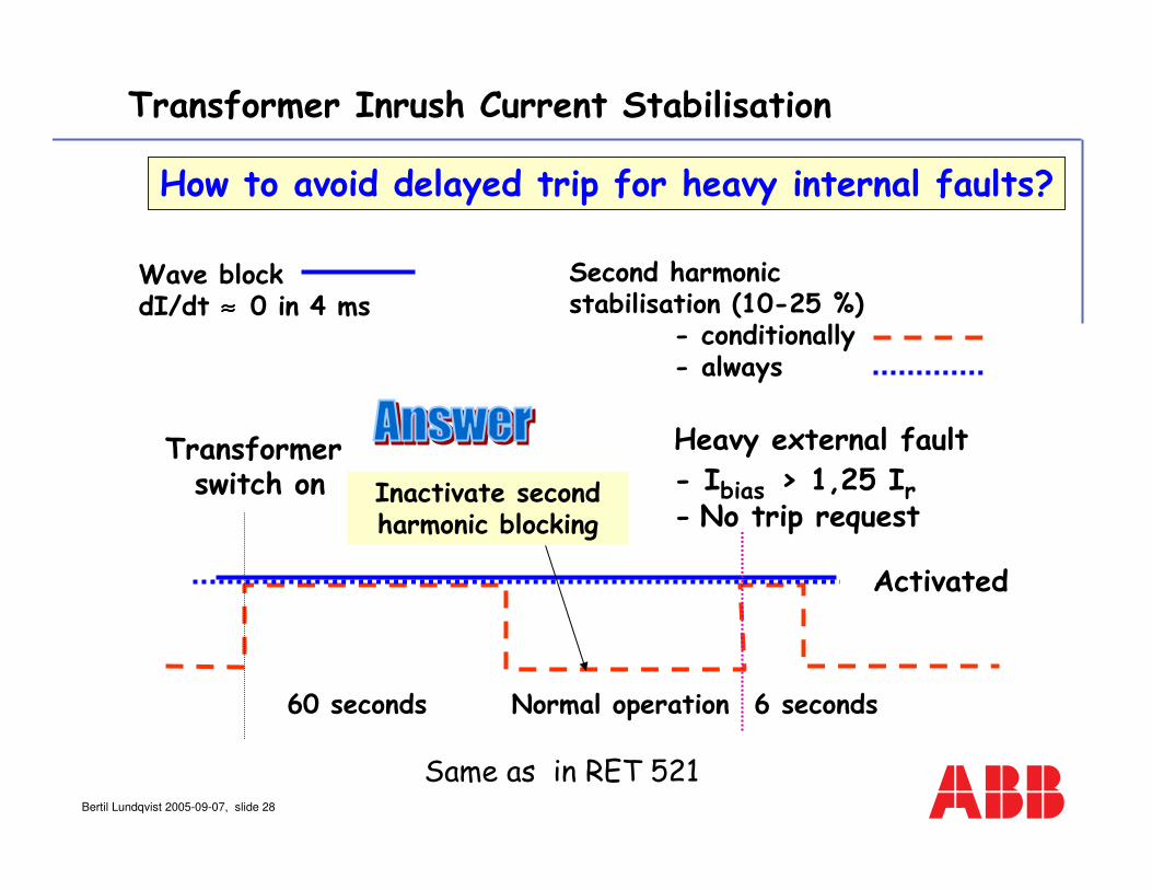
Second harmonicstabilisation (10-25 %)
- conditionally- always
Wave blockdI/dt ≈≈≈≈ 0 in 4 ms
Transformerswitch on
60 seconds 6 seconds
Heavy external fault- Ibias > 1,25 Ir- No trip request
Activated
How to avoid delayed trip for heavy internal faults?
Transformer Inrush Current Stabilisation
Inactivate second harmonic blocking
Normal operation
Same as in RET 521
Bertil Lundqvist 2005-09-07, slide 29
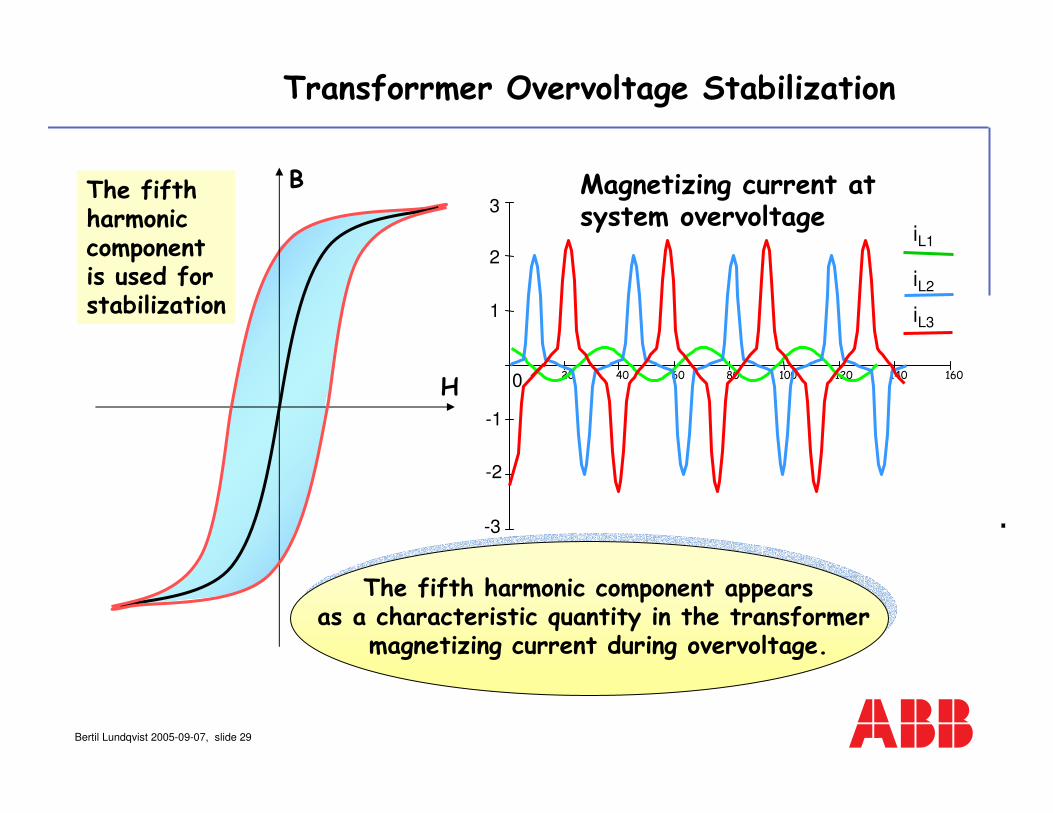
B
H
The fifth harmonic component appears as a characteristic quantity in the transformer
magnetizing current during overvoltage.
0 20 40 60 80 100 120 140 160
-3
-2
-1
1
2
3Magnetizing current at system overvoltage
iL1
iL2
iL3
Transforrmer Overvoltage Stabilization
The fifth harmonic componentis used for stabilization

Bertil Lundqvist 2005-09-07, slide 30
• Protection independent direct transfer trip
• Security achieved with bit check
• Separate transfer trip via the channel for the differential protection
• 8 transfer trip channels
Trip R
Trip S
Trip T
Comm.
Difff.etc..
Transfer trip.
Ι
U
Transfer trip
Bertil Lundqvist 2005-09-07, slide 31
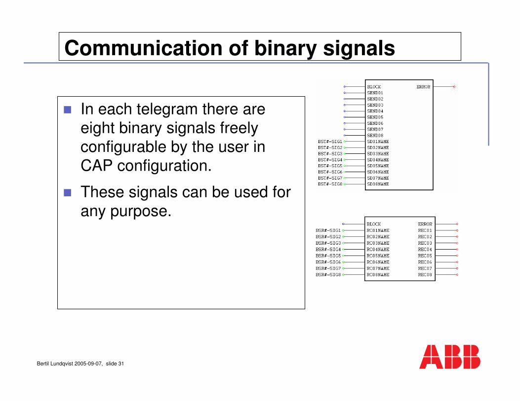
Communication of binary signals
In each telegram there are eight binary signals freely
configurable by the user in CAP configuration.
These signals can be used for any purpose.
Bertil Lundqvist 2005-09-07, slide 32
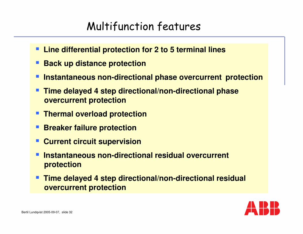
Line differential protection for 2 to 5 terminal lines
Back up distance protection
Instantaneous non-directional phase overcurrent protection
Time delayed 4 step directional/non-directional phaseovercurrent protection
Thermal overload protection
Breaker failure protection
Current circuit supervision
Instantaneous non-directional residual overcurrentprotection
Time delayed 4 step directional/non-directional residualovercurrent protection
Multifunction features
Bertil Lundqvist 2005-09-07, slide 33
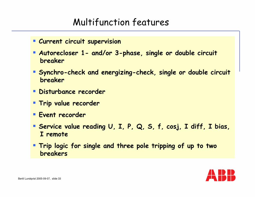
Current circuit supervision
Autorecloser 1- and/or 3-phase, single or double circuit breaker
Synchro-check and energizing-check, single or double circuit breaker
Disturbance recorder
Trip value recorder
Event recorder
Service value reading U, I, P, Q, S, f, cosj, I diff, I bias, I remote
Trip logic for single and three pole tripping of up to two breakers
Multifunction features
Bertil Lundqvist 2005-09-07, slide 34
A differential current does not always mean a fault, but -
Idiff
Line Differential Protection

Bertil Lundqvist 2005-09-07, slide 35