Embed Size (px)
Citation preview
Guidelines For Landscape Drip Irrigation
Systems
Prepared by the
Arizona Landscape Irrigation Guidelines Committee
July 2001
www.amwua.org
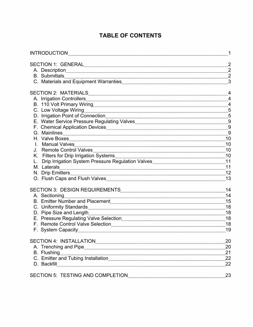
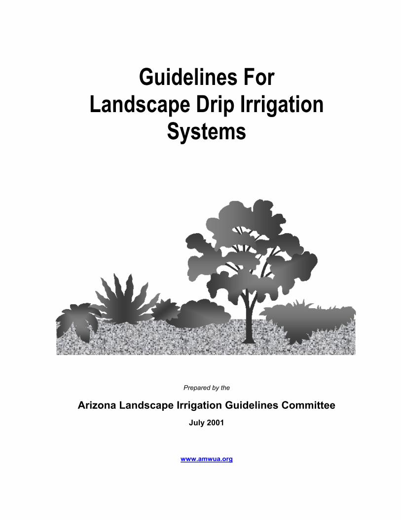
TABLE OF CONTENTS INTRODUCTION 1 SECTION 1: GENERAL 2
A. Description 2 B. Submittals 2 C. Materials and Equipment Warranties 3
SECTION 2: MATERIALS 4 A. Irrigation Controllers 4 B. 110 Volt Primary Wiring 4 C. Low Voltage Wiring 5 D. Irrigation Point of Connection 5 E. Water Service Pressure Regulating Valves 9 F. Chemical Application Devices 9 G. Mainlines 9 H. Valve Boxes 10 I. Manual Valves 10 J. Remote Control Valves 10 K. Filters for Drip Irrigation Systems 10 L. Drip Irrigation System Pressure Regulation Valves 11 M. Laterals 11 N. Drip Emitters 12 O. Flush Caps and Flush Valves 13
SECTION 3: DESIGN REQUIREMENTS 14 A. Sectioning 14 B. Emitter Number and Placement 15 C. Uniformity Standards 18 D. Pipe Size and Length 18 E. Pressure Regulating Valve Selection 18 F. Remote Control Valve Selection 18 F. System Capacity 19
SECTION 4: INSTALLATION 20 A. Trenching and Pipe 20 B. Flushing 21 C. Emitter and Tubing Installation 22 D. Backfill 22
SECTION 5: TESTING AND COMPLETION 23
SECTION 6: MAINTENANCE 24 A. Regular Maintenance 24 B. Semi-Annual Maintenance 26 C. Annual Maintenance 26
SECTION 7: REPAIR 27 SECTION 8: WATERING 28
A. Water Conservation 28 B. Watering Schedules 28 C. Water Requirements 29 D. Watering Frequency 29 E. Watering Time 29
SECTION 9: DEFINITIONS 30 SECTION 10: REFERENCES 32 APPENDIX A: STANDARD INSTALLATION DETAIL
FOR IRRIGATION CONTROLLERS 33 APPENDIX B: STANDARD INSTALLATION DETAILS
FOR LOW VOLTAGE WIRE SPLICES 34 Direct Bury Connector 34 Dry Splice Connector 34 Water-Proof Wire Nut 34
APPENDIX C: STANDARD INSTALLATION DETAILS AND EXAMPLES
FOR POINTS OF CONNECTION 35 Before Installation 35 After Installation 35
APPENDIX D: STANDARD INSTALLATION DETAILS
FOR BACKFLOW PREVENTION ASSEMBLIES 36 Atmospheric Vacuum Breaker 36 Pressure Vacuum Breaker 37 Reduced Pressure Principle Backflow Preventer 38
APPENDIX E: STANDARD INSTALLATION DETAILS
FOR VALVE BOXES, VALVES, FILTERS, AND PRESSURE REGULATORS 39 Valve Box 39 Valve, Filter, and Pressure Reducer 40
APPENDIX F: STANDARD INSTALLATION DETAILS
FOR FLUSH CAPS AND FLUSH VALVES 41
Flush Cap 41 Flush Valve 42
APPENDIX G: EMITTER PLACEMENT AND WETTING PATTERN EXAMPLES 43
Loop at Installation 43 Loop at Maturity 43
Wetting Pattern Examples 44 APPENDIX H: EMISSION UNIFORMITY 45 APPENDIX I: STANDARD INSTALLATION DETAILS AND EXAMPLES
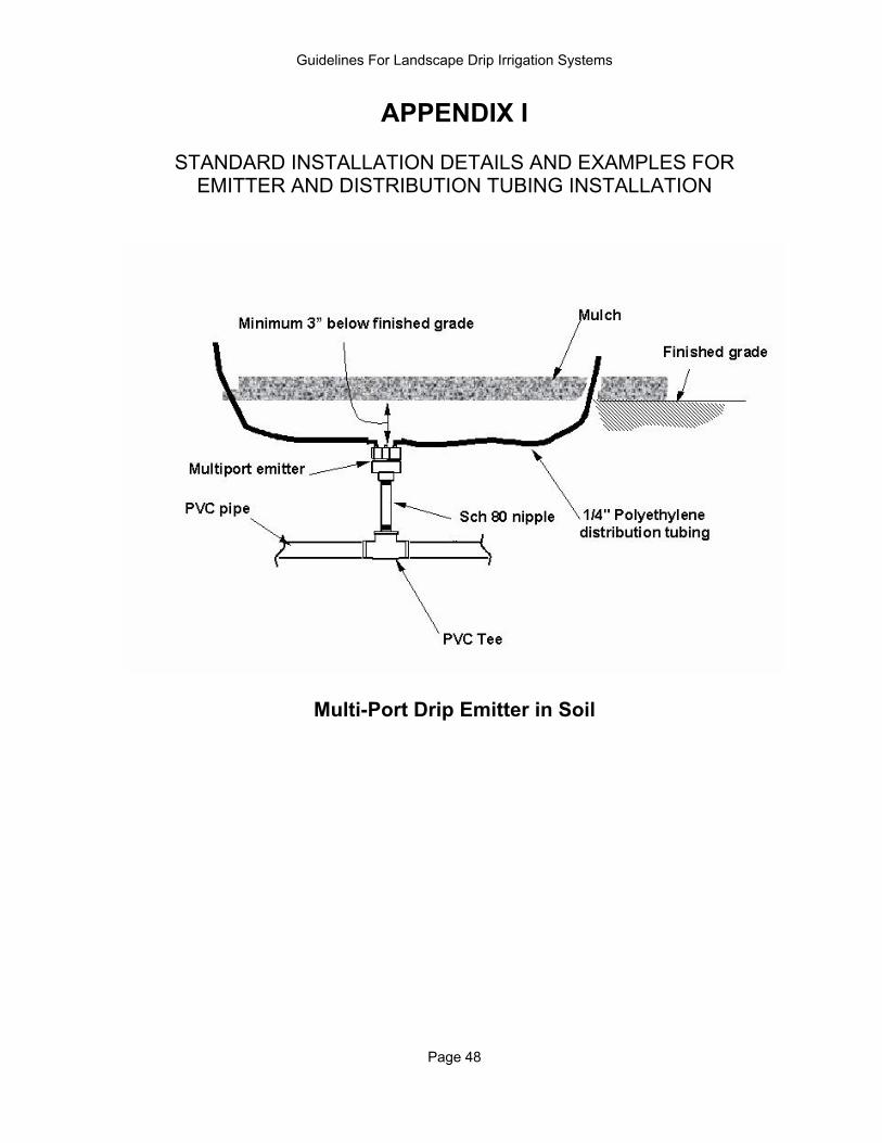
FOR EMITTER AND DISTRIBUTION TUBING INSTALLATION 47 Multi-Port Drip Emitter in Valve Box 47 Multi-Port Drip Emitter in Ground 48
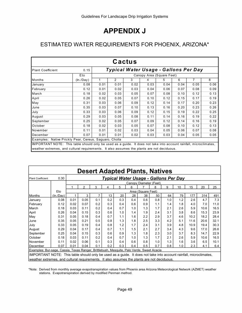
APPENDIX J: ESTIMATED WATER REQUIREMENTS 49
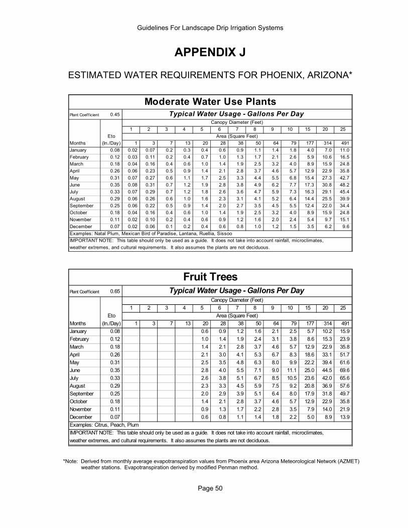
PHOENIX, ARIZONA Cactus 49 Desert Adapted Plants, Natives 49 Moderate Water Use Plants 50 Fruit Trees 50 High Water Use Plants 51 Very High Water Use Plants 51
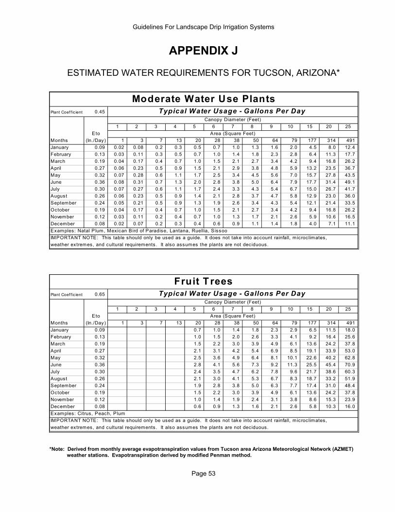
TUCSON, ARIZONA Cacti 52 Desert Adapted Plants, Natives 52 Moderate Water Use Plants 53 Fruit Trees 53 High Water Use Plants 54 Very High Water Use Plants 54
APPENDIX K: SUGGESTED WATERING FREQUENCIES 55 APPENDIX L: RECOMMENDED MAXIMUM WATERING TIME
TO PREVENT DEEP SEEPAGE 56 APPENDIX M: A SIMPLIFIED APPROACH FOR DETERMINING
LANDSCAPE WATERING SCHEDULES 57
APPENDIX N: IMPORTANT TELEPHONE NUMBERS 58
Guidelines For Landscape Drip Irrigation Systems
Page 1
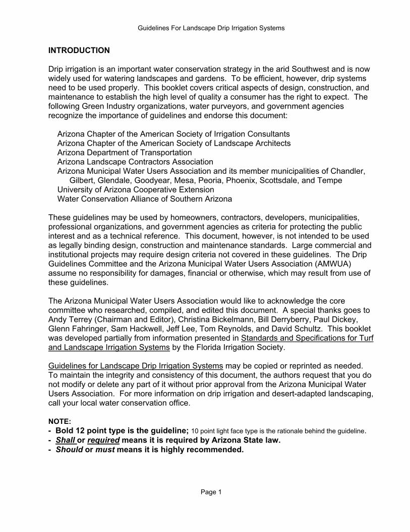
INTRODUCTION Drip irrigation is an important water conservation strategy in the arid Southwest and is now widely used for watering landscapes and gardens. To be efficient, however, drip systems need to be used properly. This booklet covers critical aspects of design, construction, and maintenance to establish the high level of quality a consumer has the right to expect. The following Green Industry organizations, water purveyors, and government agencies recognize the importance of guidelines and endorse this document:
Arizona Chapter of the American Society of Irrigation Consultants Arizona Chapter of the American Society of Landscape Architects Arizona Department of Transportation Arizona Landscape Contractors Association Arizona Municipal Water Users Association and its member municipalities of Chandler, Gilbert, Glendale, Goodyear, Mesa, Peoria, Phoenix, Scottsdale, and Tempe University of Arizona Cooperative Extension Water Conservation Alliance of Southern Arizona
These guidelines may be used by homeowners, contractors, developers, municipalities, professional organizations, and government agencies as criteria for protecting the public interest and as a technical reference. This document, however, is not intended to be used as legally binding design, construction and maintenance standards. Large commercial and institutional projects may require design criteria not covered in these guidelines. The Drip Guidelines Committee and the Arizona Municipal Water Users Association (AMWUA) assume no responsibility for damages, financial or otherwise, which may result from use of these guidelines. The Arizona Municipal Water Users Association would like to acknowledge the core committee who researched, compiled, and edited this document. A special thanks goes to Andy Terrey (Chairman and Editor), Christina Bickelmann, Bill Derryberry, Paul Dickey, Glenn Fahringer, Sam Hackwell, Jeff Lee, Tom Reynolds, and David Schultz. This booklet was developed partially from information presented in Standards and Specifications for Turf and Landscape Irrigation Systems by the Florida Irrigation Society. Guidelines for Landscape Drip Irrigation Systems may be copied or reprinted as needed. To maintain the integrity and consistency of this document, the authors request that you do not modify or delete any part of it without prior approval from the Arizona Municipal Water Users Association. For more information on drip irrigation and desert-adapted landscaping, call your local water conservation office. NOTE: - Bold 12 point type is the guideline; 10 point light face type is the rationale behind the guideline. - Shall or required means it is required by Arizona State law. - Should or must means it is highly recommended.
Guidelines For Landscape Drip Irrigation Systems
Page 2
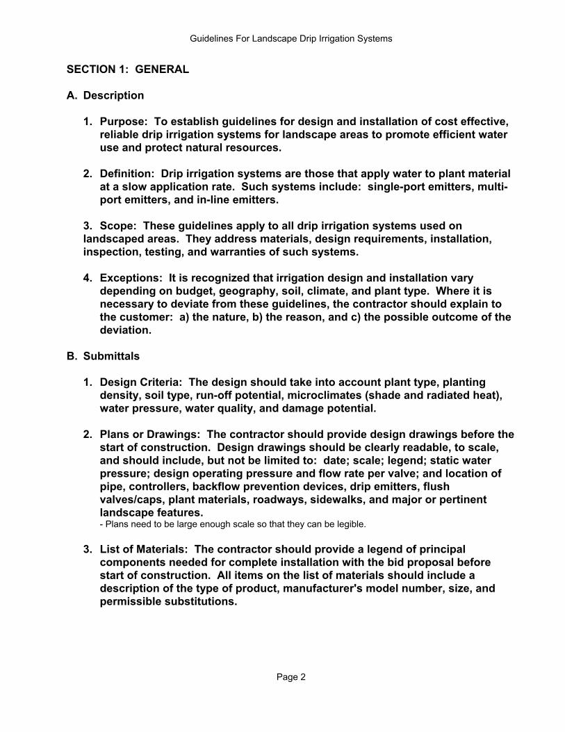
SECTION 1: GENERAL A. Description 1. Purpose: To establish guidelines for design and installation of cost effective, reliable drip irrigation systems for landscape areas to promote efficient water use and protect natural resources. 2. Definition: Drip irrigation systems are those that apply water to plant material at a slow application rate. Such systems include: single-port emitters, multi- port emitters, and in-line emitters. 3. Scope: These guidelines apply to all drip irrigation systems used on landscaped areas. They address materials, design requirements, installation, inspection, testing, and warranties of such systems. 4. Exceptions: It is recognized that irrigation design and installation vary depending on budget, geography, soil, climate, and plant type. Where it is necessary to deviate from these guidelines, the contractor should explain to the customer: a) the nature, b) the reason, and c) the possible outcome of the deviation. B. Submittals 1. Design Criteria: The design should take into account plant type, planting
density, soil type, run-off potential, microclimates (shade and radiated heat), water pressure, water quality, and damage potential.
2. Plans or Drawings: The contractor should provide design drawings before the
start of construction. Design drawings should be clearly readable, to scale, and should include, but not be limited to: date; scale; legend; static water pressure; design operating pressure and flow rate per valve; and location of pipe, controllers, backflow prevention devices, drip emitters, flush valves/caps, plant materials, roadways, sidewalks, and major or pertinent landscape features.
- Plans need to be large enough scale so that they can be legible. 3. List of Materials: The contractor should provide a legend of principal
components needed for complete installation with the bid proposal before start of construction. All items on the list of materials should include a description of the type of product, manufacturer's model number, size, and permissible substitutions.
Guidelines For Landscape Drip Irrigation Systems
Page 3
4. Instructions: The contractor should provide operating instructions and maintenance schedules for the system to the owner. The contractor should include estimated monthly water needs, a start-up watering schedule, and a typical watering schedule for the mature landscape based on a normal weather year according to seasonal weather changes. Irrigation schedules should include start times, watering days, and run time per station.
5. As-Built Drawings: The contractor should provide drawings and plans
corrected or amended to show all changes in the design. Notes on deviations should be included with the as-builts.
6. Construction Permits: Construction permits are required for installation of all
commercial irrigation systems. Some municipalities also require permits for residential irrigation systems. Permits specifically cover installation of backflow preventers and standard voltage electrical work. Specific local requirements must be verified before installation.
7. Testing and Inspection Certifications: Testing certifications per building code
for backflow preventers and standard voltage electrical work shall be obtained.
C. Materials and Equipment Warranties 1. Installation: The contractor should assume full responsibility for the proper
installation of the system. Irrigation system components should be specified and installed only within the capabilities and limitations stated by the manufacturer, these guidelines, and any applicable local codes.
2. Guarantees: The contractor should guarantee construction for one year from
date of completion. 3. Claims: The contractor should satisfy any guarantee claims within 15 days of
receipt of the claim.
Guidelines For Landscape Drip Irrigation Systems
Page 4
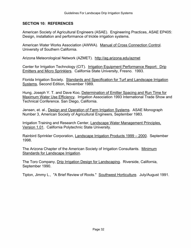
SECTION 2: MATERIALS A. Irrigation Controllers STANDARD DETAIL- APPENDIX A 1. All irrigation controllers shall be UL listed and properly grounded according to
manufacturers' recommendations and local electric codes. - Proper installation and grounding are essential to avoid electrocution. 2. The controller housing or enclosure should protect the controller from the
environment in which it is installed. - Weather exposure shortens controller life. 3. The controller should be capable of separate watering programs for each
significantly different hydrozone. - Different plant types require irrigation at different intervals. 4. The irrigation controller should include running increments of minutes and
hours. - Most drip systems require a cycle time of at least one hour. - Repeating cycles may serve as an alternative to longer run times. 5. Controllers used in areas where run-off can be a problem should be capable of
implementing a minimum of three start times per day. - Repeating cycles decreases run-off. 6. Additional equipment such as rain switches and soil moisture sensors can
provide additional water savings. 7. Electronic controllers should be installed at least 12 feet from motors, air
conditioners, or other electrical equipment that emit electromagnetic frequencies (EMFs).
- EMFs can cause the controller to malfunction. B. 110 Volt Primary Wiring 1. All primary wiring should be UL listed #12 gauge with #10 gauge ground.
- #12 gauge wire provides durability. Larger ground wire provides more safety for the user and the equipment.
2. All primary wiring installed below ground shall be installed in conduit per
electrical code. - Conduit helps prevent the wire from being accidentally severed. 3. All primary wiring installed above ground shall be installed in gray schedule
40, PVC electrical conduit, flexible metallic conduit, or electrical metallic conduit.
- 110 volt wiring must not be exposed to the elements or the user.
4. The controller should be connected to a dedicated electrical breaker. - Controllers on separate breakers have less chance of power failures.
Guidelines For Landscape Drip Irrigation Systems
Page 5
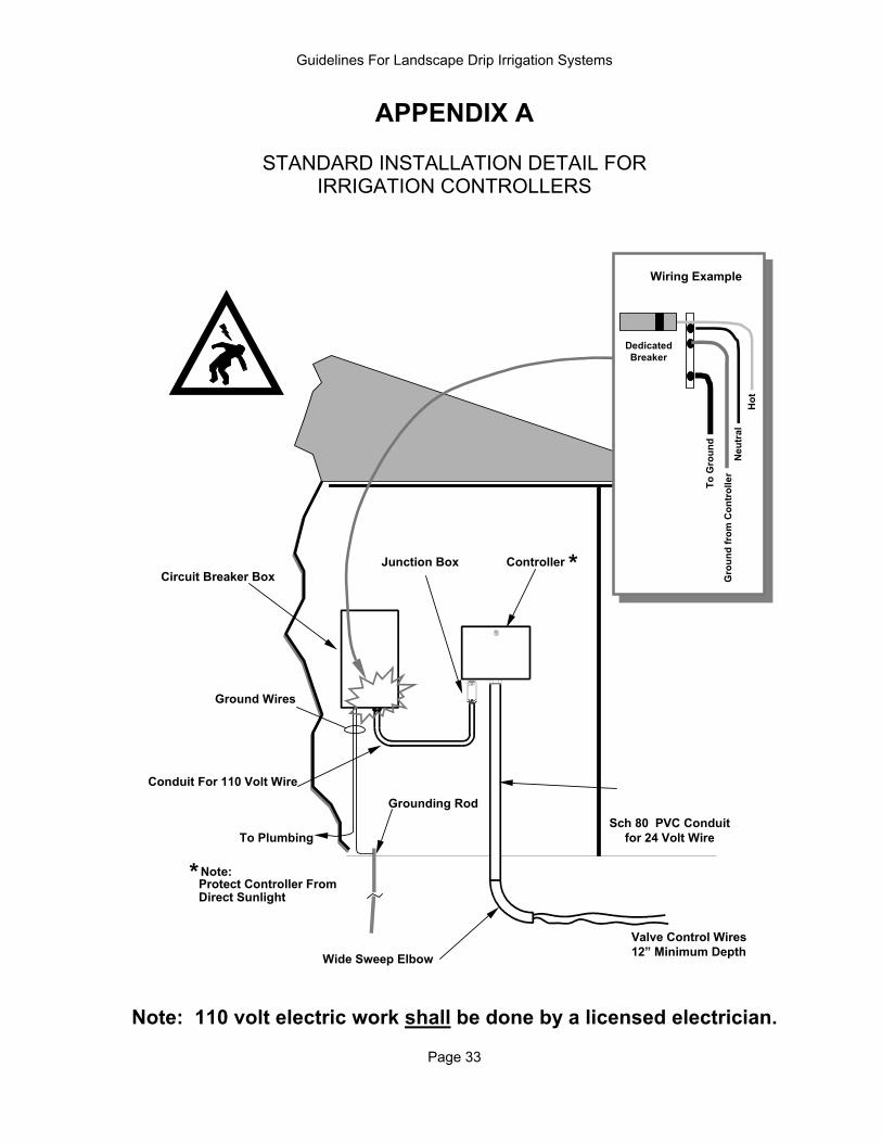
C. Low Voltage Wiring EXAMPLES - APPENDIX B 1. All low voltage wire that is directly buried must be UL listed, direct burial wire.
#16 gauge or thicker wire should be used, based on the length of the run electrical demand. Wire sizing should be based on electrical demand and length of run. #18 gauge wire is acceptable for residential installations where multi-strand wire cable is used and all valves are within 150 feet of the controller. - Smaller gauge, poorly insulated wire allows unidentifiable current leakage and early failure.
2. Connections are to be made waterproof with devices specifically designed for
direct burial. Splices should be placed in a valve box. - Poor splices are the cause of most troubleshooting expense. 3. Use expansion coils at wire connections. - Expansion coils allow for extra wire to make repairs. 4. Leave slack in wires at turns.
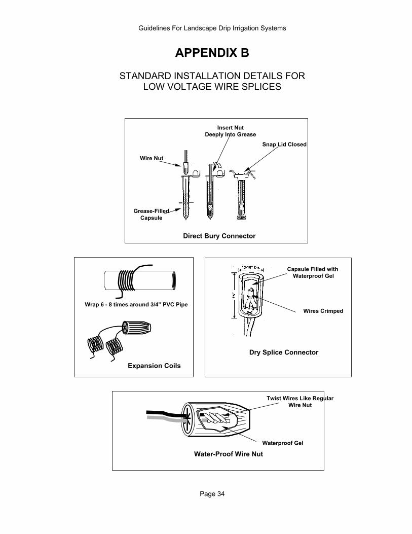
- Wires expand and contract with temperature. Extra wire in the corners keeps wire from fatiguing. D. Irrigation Points of Connection STANDARD DETAILS AND EXAMPLES - APPENDIX C 1. Water Source a. Where possible, the point of connection should be before the water line
enters the building.
b. The tap should be sized to meet the water demand of the irrigation system.
c. Tap size should be at least ¾” for residential installations. d. The water supply should not be down stream from any soft-water system. 2. Pipe Between Point of Connection and Backflow Preventer a. Type K copper pipe or schedule 40 PVC pipe should be used below ground
between the point of connection and the backflow preventer. - Galvanized pipe eventually corrodes and can clog emitters.
b. Pipes of dissimilar metals should be connected with a dielectric fitting. - Galvanized pipe will quickly deteriorate if connected to copper pipe.
c. A manual shut-off valve should be installed between the potable water supply and the backflow prevention unit. A ball valve is recommended. - A manual shut-off allows installation and repair without interrupting flow to the house. - A manual shut-off allows for winterizing the downstream components of the point of connection. - Ball valves must be opened and closed slowly.
Guidelines For Landscape Drip Irrigation Systems
Page 6
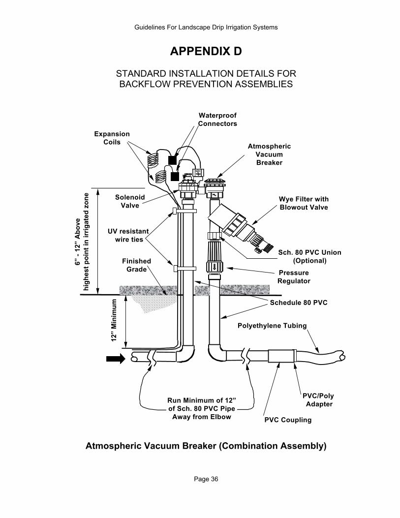
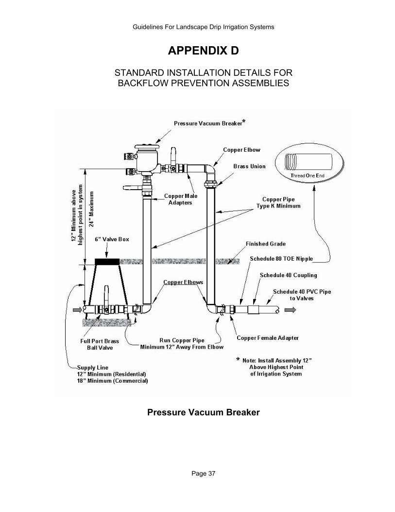
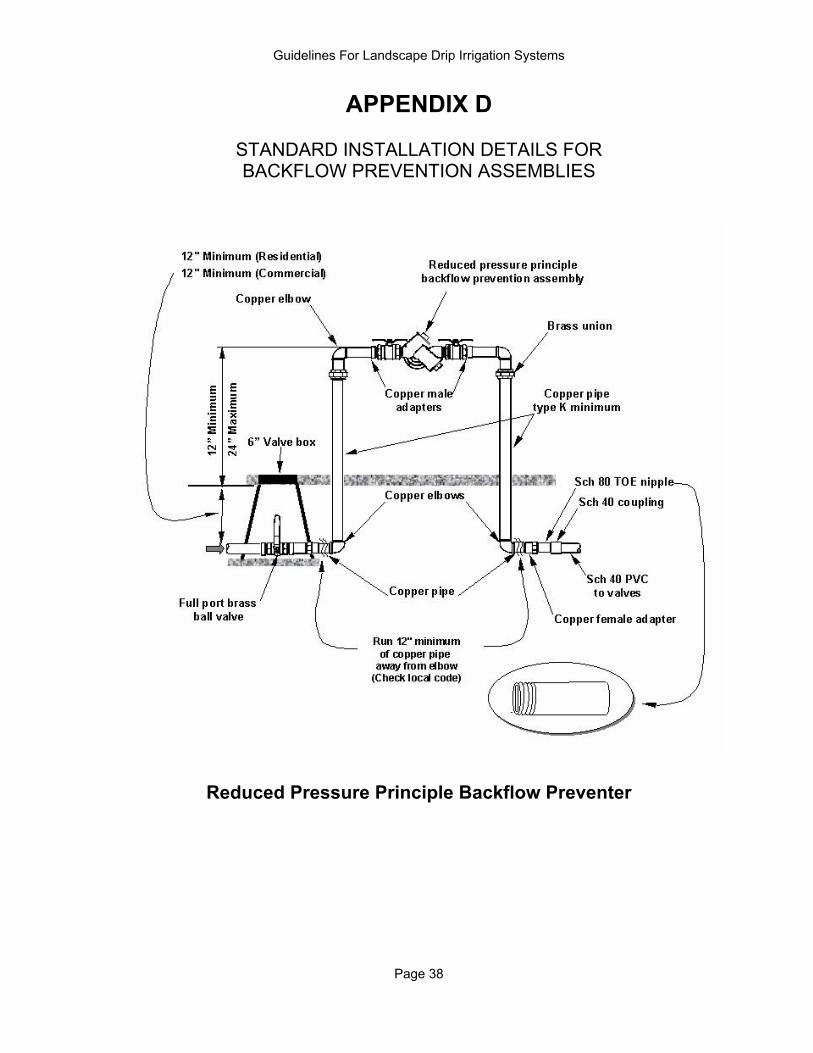
3. Backflow Prevention Assemblies STANDARD DETAILS- APPENDIX D
Provide backflow prevention assemblies at all connections with potable water supplies according to county, municipal, or other applicable codes. It is the responsibility of the designer to specify the assembly according to all applicable regulations. It is the contractor's responsibility to see that the assembly is installed properly and that it passes inspection. Three types of backflow preventers are approved by the AWWA:
a. Reduced Pressure Backflow Prevention Assembly (RP): Application:
1) Required when landscape area is serviced by more than one water source (multiple meters).
2) Required when fertilizer or chemical injectors are used. 3) Required when area being irrigated is higher than water source. 4) Commercial installations. Installation Requirements: 1) Irrigation valves shall be installed after the RP. 2) Shall be installed at least 12 inches above ground. 3) Fertilizer or chemical injectors, if used, shall be installed after the RP.
4) Shall be installed at least 12 inches away from walls. 5) Test ports shall be easily serviceable
Advantages: 1) Multiple control valves can be placed in an irrigation box(es), after the
assembly, anywhere in the landscape. 2) Assembly can be tested to make sure it is working properly. 3) Components of the irrigation system can be higher than the RP. Disadvantage: 1) Greater friction losses through an RP than other backflow prevention devices.
Guidelines For Landscape Drip Irrigation Systems
Page 7
b. Pressure Vacuum Breaker (PVB) Application: 1) Single water source to the property. 2) Area being irrigated is lower than the backflow prevention assembly. 3) Light commercial and residential installations. Installation Requirements: 1) Shall be installed 12 inches above the highest point on the system. 2) Shall be installed at least 12 inches away from walls. 3) Irrigation valves shall be installed after the assembly. Advantages: 1) Multiple control valves can be placed in an irrigation box(es), after the
assembly, anywhere in the landscape. 2) Assembly can be tested to make sure it is working properly. Disadvantages: 1) Does not protect against back pressure. c. Atmospheric Vacuum Breaker (AVB) Application: 1) Single water source serving the property. 2) Area being irrigated is lower than water source. 3) Residential installations. Installation Requirements: 1) Shall be installed after the irrigation valves. 2) Plastic AVBs and piping must be protected from the sun. 3) Shall be installed at least 6 inches above the highest point after the valve; 12
inches is preferred. 4) Shall be installed at least 12 inches away from walls. Advantages: 1) Easiest to install. Disadvantages: 1) Atmospheric Vacuum Breakers cannot be tested and give a false sense of
security. 2) For every control valve, an AVB is required. 3) Sun damages plastic valves.
Guidelines For Landscape Drip Irrigation Systems
Page 8
4. Above Ground Pipe and Fittings at the Point of Connection a. Type K copper pipe should be used for all PVB and RP installations. - Above ground components are exposed to the elements and are subject to abuse. - Galvanized pipe eventually corrodes and can clog emitters. - Unprotected PVC pipe deteriorates when exposed to sunlight. - Copper pipe installed in corrosive soils should be wrapped with PVC tape. b. Schedule 80 PVC pipe and fittings should be used for AVB installations in
residential settings. - Schedule 80 PVC pipe should still be protected from direct sunlight. c. At least one union shall be installed within at least one foot of the backflow
prevention assembly. - There shall be a nondestructive method for component replacement.
- The American Water Works Association standard requires backflow prevention devices to be installed with unions.
d. A manual shut-off should be installed between the potable water supply
and the backflow prevention unit. A ball valve is preferred. - A manual shut-off allows installation and repair without interrupting flow to the house. - A manual shut-off allows for winterizing the downstream components of the point of connection. - Ball valves must be opened and closed slowly.
5. Filters and Strainers at the Point of Connection (Optional) - Strainers are used to protect RP devices from malfunctioning. - Strainers are not intended for filtering water for the drip irrigation components. a. A strainer may be installed before the backflow prevention unit if the
following conditions are met: 1) The opening in the branch of the filter must have a threaded plug. 2) The filter should be rated at twice the static pressure. Brass housing
should be used. 3) Stainless steel mesh or disk filters should be used. 4) There must be a minimum 1-inch air gap between the filter plug and the
water ponding level below the backflow preventer. 5) A pressure reducer should be installed if the water pressure is greater
than 90 psi. - Filters placed ahead of backflow preventers protect the preventers, valves, and emitters from contamination.
b. Filters and strainers should be installed according to the manufacturers’
recommendations and in a way that allows easy servicing. c. Filters and strainers should have a minimum operating pressure of twice
the static water pressure. - Inadequately designed filters can rupture under high water pressure.
Guidelines For Landscape Drip Irrigation Systems
Page 9
E. Water Service Pressure Regulating Valves 1. An adjustable brass pressure reducing valve should be installed if the water
static water pressure is greater than 80 psi. 2. The pressure regulating valve should be installed at the point of connection
before the backflow preventer. 3. Pressure should be reduced to between 50 and 75 psi. - Reduced pressure is needed to protect the irrigation system. F. Chemical Application Devices (Optional) 1. If installed, chemical application devices should be located and sized
according to manufacturers' recommendations. 2. Injection systems shall be installed downstream from an approved reduced-
pressure-principle backflow preventer. - Chemical injection is a high health hazard requiring maximum protection. 3. A filter should be installed downstream of any application device. - Chemicals often coagulate and clog emitters. 4. Chemical application devices shall be installed in accordance with local health
and safety codes. G. Mainlines (Pipe located before the valves) 1. Transitions from copper to PVC should be made by placing a male PVC fitting
into a female copper adapter. -This method reduces the potential for failure of the female fitting. 2. Schedule 80 threaded fittings are recommended for connections between PVC
and copper pipe. -Threaded Schedule 40 PVC connections are vulnerable to breakage. 3. Schedule 40 PVC pipe should be used for all lines under constant pressure.
- Pipe must be thick enough to withstand water hammer and crushing from normal traffic wear. 4. Mainlines should be installed at least one foot deep. Apply at least two inches
of rock-free backfill around the entire pipe. - Rock can damage pipe. 5. PVC sleeves should be used in new installations where PVC pipe is run under
concrete slabs or asphalt driveways. Sleeves should be twice the pipe diameter.
- Weight of vehicles and damage pipe.

Guidelines For Landscape Drip Irrigation Systems
Page 10
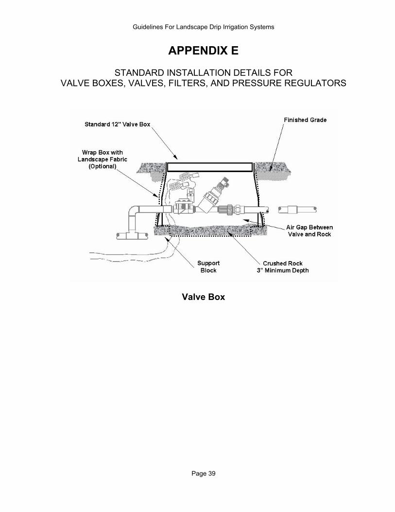
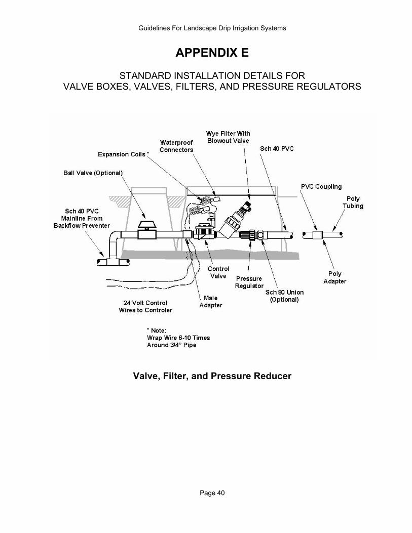
H. Valve Boxes STANDARD DETAIL- APPENDIX E 1. Valve boxes should be constructed to withstand traffic loads common to the
area in which they are installed. 2. Valve boxes should be large enough to allow maintenance of remote control
valves, filters, and pressure regulators without excavation. I. Manual Valves 1. Valves must have a pressure rating equal to or greater than the maximum
pressure of the system plus anticipated surge pressures, but not less than 100 psi.
- Valves rated at lesser working pressures will inevitably leak and fail. 2. Plastic valves should be protected from direct sunlight. Brass valves are
highly recommended for installations above ground. - Plastic deteriorates when exposed to direct sunlight. 3. Ball valves are recommended. - Ball valves must be turned off and on slowly. J. Remote Control Valves STANDARD DETAIL- APPENDIX E Control valves should be sized and selected based on the minimum and
maximum flow rate recommended by the manufacturer. - Some sprinkler valves do not function properly at low flows characteristic of drip irrigation systems.
K. Filters for Drip Irrigation Systems STANDARD DETAIL- APPENDIX E 1. Filters must be installed to prevent dirt and debris from clogging emitters. 2. A 150-200 mesh screen should be used unless otherwise allowed by the
manufacturer. 3. Filter screens should be stainless steel. - Disc filters may be used in place of screen filters. - Plastic fabric screens are not durable. 4. Filters and strainers should be installed according to the manufacturers’
recommendations and in a way that allows easy servicing. 5. Filters and strainers should have a minimum operating pressure of twice the
static water pressure. - Inadequately designed filters can rupture under high water pressure.
Guidelines For Landscape Drip Irrigation Systems
Page 11
L. Drip Irrigation System PRVs STANDARD DETAIL- APPENDIX E 1. Pressure for each valve section should be regulated to the manufacturer's
recommended range for the drip emitters. - High pressure causes tubing to leak and causes emitters to not work properly. 2. The pressure reducing valve should be sized for the design flow rate of the
irrigated zone. 3. Under most circumstances, install PRVs after the Remote Control Valves. - Remote control valves function better at higher pressures. 4. Installing a union or swivel connector at the PRV is recommended so that the
unit can be serviced or replaced without cutting into pipe. 5. PRVs can be placed in a separate valve box. - Separate valve boxes allow for easy access. M. Laterals (Pipe after valves) 1. PVC Pipe
a. Class 200 or heavier pipe should be used.
b. Pipe should be sized to limit flow velocity to 5 feet per second or less. - High velocity causes excessive friction losses. High velocity can damage equipment.
c. PVC sleeves should be used in new installations where PVC pipe is run
under concrete slabs or asphalt driveways. Sleeves should be twice the pipe diameter. - Weight of vehicles and damage pipe.
d. Schedule 40 PVC pipe should be used under roadways. - Weight of vehicles and damage pipe.
2. Polyethylene Tubing a. Half-inch polyethylene tubing (1/2"-3/4" nominal diameter) should only be
used downstream of remote control valves and pressure regulators. - Polyethylene fittings are not designed for high or sustained pressure. b. Polyethylene distribution “spaghetti” tubing (1/8"-1/4" nominal diameter)
should only be used between the half-inch polyethylene lateral and the plants.
Guidelines For Landscape Drip Irrigation Systems
Page 12
c. Vinyl tubing is not recommended. - Vinyl becomes soft and stretches when hot, thus causing the connection to leak or come apart. It becomes hard and brittle when cold. - Vinyl deteriorates with age.
d. Fittings should be specifically manufactured for the type and dimensions
of the polyethylene pipe used. - Tubing and fittings are not generally standardized between manufacturers. - Improperly sized fittings cause water leaks. e. PVC sleeves should be used in new installations where polyethylene is run
under concrete slabs or asphalt driveways. Sleeves should be twice the pipe diameter.
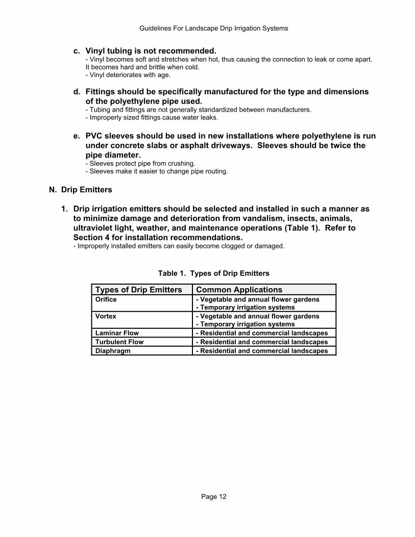
- Sleeves protect pipe from crushing. - Sleeves make it easier to change pipe routing. N. Drip Emitters 1. Drip irrigation emitters should be selected and installed in such a manner as
to minimize damage and deterioration from vandalism, insects, animals, ultraviolet light, weather, and maintenance operations (Table 1). Refer to Section 4 for installation recommendations.
- Improperly installed emitters can easily become clogged or damaged.
Table 1. Types of Drip Emitters
Types of Drip Emitters Common Applications Orifice - Vegetable and annual flower gardens
- Temporary irrigation systems Vortex - Vegetable and annual flower gardens
- Temporary irrigation systems Laminar Flow - Residential and commercial landscapes Turbulent Flow - Residential and commercial landscapes Diaphragm - Residential and commercial landscapes
Guidelines For Landscape Drip Irrigation Systems
Page 13
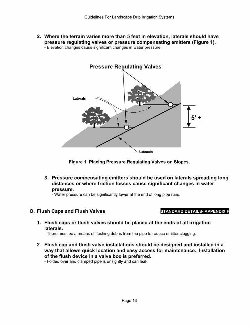
2. Where the terrain varies more than 5 feet in elevation, laterals should have
pressure regulating valves or pressure compensating emitters (Figure 1). - Elevation changes cause significant changes in water pressure.
5’ +
Pressure Regulating Valves
Submain
Laterals
Figure 1. Placing Pressure Regulating Valves on Slopes.
3. Pressure compensating emitters should be used on laterals spreading long distances or where friction losses cause significant changes in water pressure. - Water pressure can be significantly lower at the end of long pipe runs.
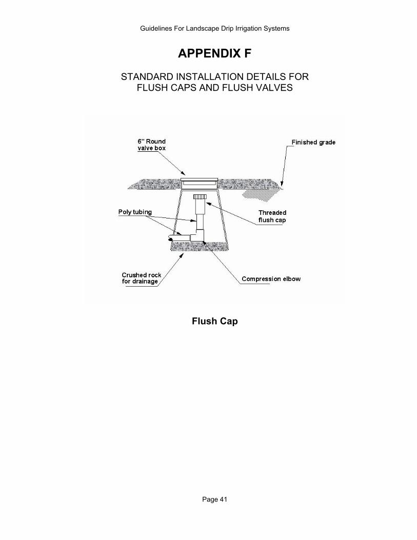
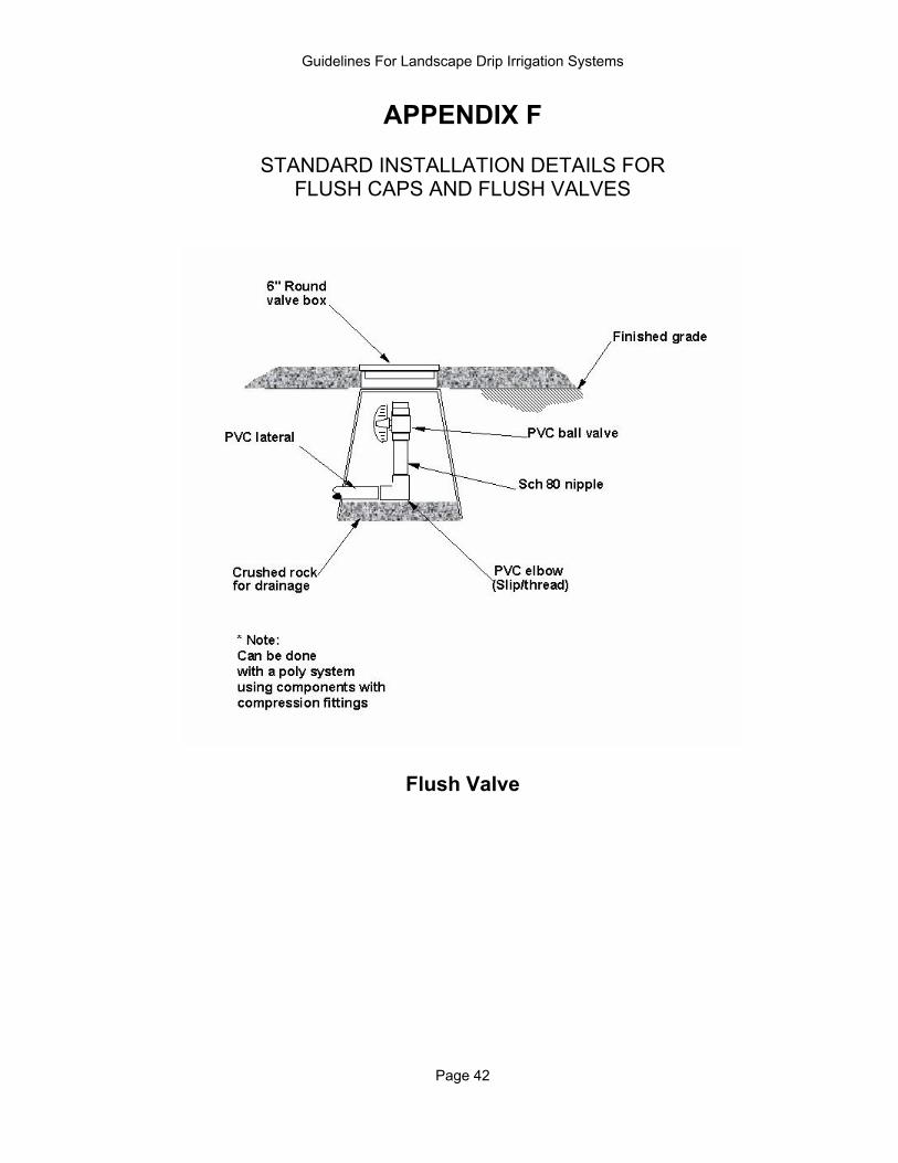
O. Flush Caps and Flush Valves STANDARD DETAILS- APPENDIX F 1. Flush caps or flush valves should be placed at the ends of all irrigation
laterals. - There must be a means of flushing debris from the pipe to reduce emitter clogging. 2. Flush cap and flush valve installations should be designed and installed in a
way that allows quick location and easy access for maintenance. Installation of the flush device in a valve box is preferred.
- Folded over and clamped pipe is unsightly and can leak.
Guidelines For Landscape Drip Irrigation Systems
Page 14
SECTION 3: DESIGN REQUIREMENTS A. Sectioning 1. Different irrigation methods must be separated. Sprinklers, bubblers,
microsprays, drip, and subsurface irrigation must be operated off of separate valves.
- Irrigation devices have different application rates. 2. Separate valves should be assigned to plant groups with widely different
watering needs (hydrozones). a. Separate desert-adapted plants from non-desert-adapted plants. - Refer to the Arizona Department of Water Resources Plant List for low-water-use species. b. Separate trees from shrubs and groundcovers.
- Shrubs and groundcovers under trees may be an exception in that the whole area is being watered at once.
c. Separate valves should be assigned to planting areas with widely different
sun exposures. Shaded areas are typically north and east exposures for a distance of 10'-15' for one story buildings and 20' - 30' for two story buildings.
- During the spring, fall, and winter, shaded areas use significantly less water. d. Separate valves should be assigned to planting areas near pavement,
reflected light, and south and west sun exposures. - Plants in hot, bright areas use significantly more water. 3. Other site-specific factors should be considered. a. Separate valves should be assigned to planting areas that have
significantly different soil types. - Different soil types have different water holding capacities. b. Separate valves should be assigned to plants in potting soil or in
containers. - Potting soil will dry out much quicker than native soil. - Plants in containers typically have restricted root systems and may need to be watered more frequently.
c. Separate valves should be assigned to plants on slopes. - Several short cycles may be required to avoid runoff. d. It may be more convenient to section landscape areas that are separated
(isolated) by walls, fences, roads, or driveways.
Guidelines For Landscape Drip Irrigation Systems
Page 15
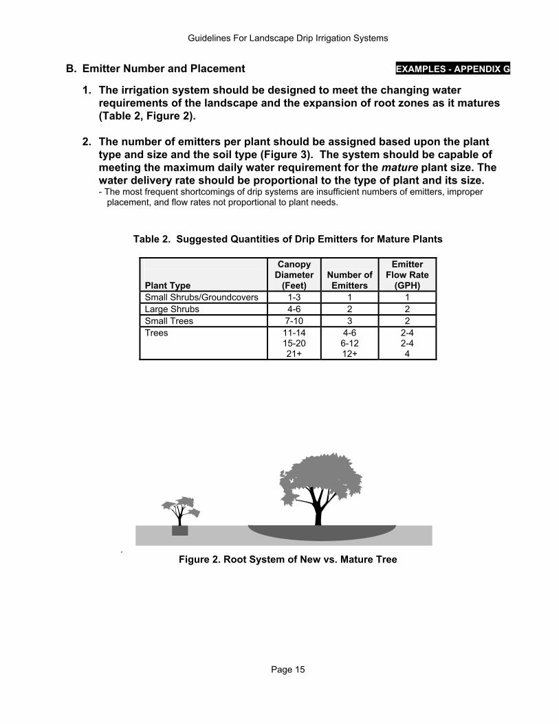
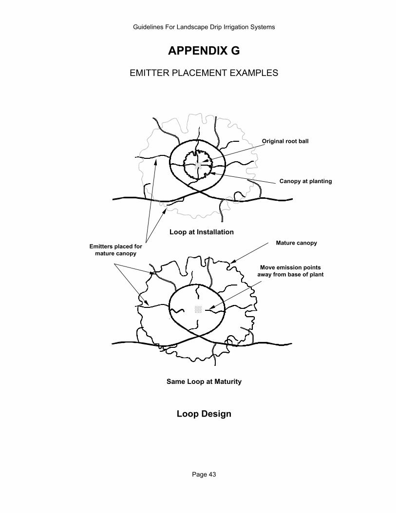
B. Emitter Number and Placement EXAMPLES - APPENDIX G 1. The irrigation system should be designed to meet the changing water
requirements of the landscape and the expansion of root zones as it matures (Table 2, Figure 2).
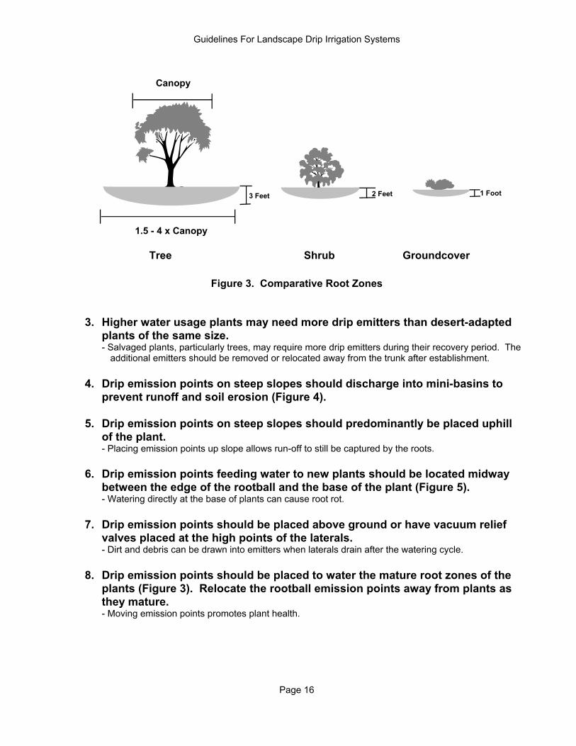
2. The number of emitters per plant should be assigned based upon the plant
type and size and the soil type (Figure 3). The system should be capable of meeting the maximum daily water requirement for the mature plant size. The water delivery rate should be proportional to the type of plant and its size. - The most frequent shortcomings of drip systems are insufficient numbers of emitters, improper
placement, and flow rates not proportional to plant needs.
Table 2. Suggested Quantities of Drip Emitters for Mature Plants
Plant Type
Canopy Diameter
(Feet)
Number of Emitters
Emitter Flow Rate
(GPH) Small Shrubs/Groundcovers 1-3 1 1 Large Shrubs 4-6 2 2 Small Trees 7-10 3 2 Trees
11-14 15-20 21+
4-6 6-12 12+
2-4 2-4 4
Figure 2. Root System of New vs. Mature Tree
Guidelines For Landscape Drip Irrigation Systems
Page 16
Canopy
1.5 - 4 x Canopy
3 Feet 2 Feet 1 Foot
Tree Shrub Groundcover
Figure 3. Comparative Root Zones 3. Higher water usage plants may need more drip emitters than desert-adapted
plants of the same size. - Salvaged plants, particularly trees, may require more drip emitters during their recovery period. The
additional emitters should be removed or relocated away from the trunk after establishment.
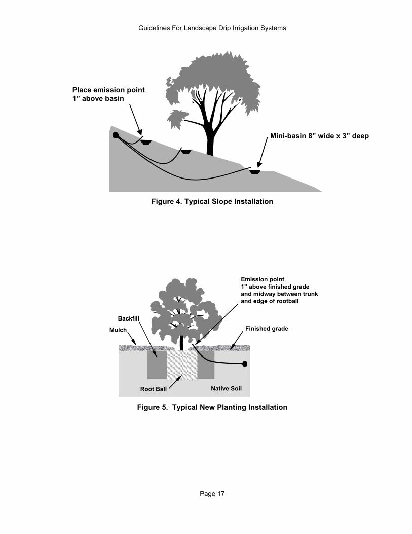
4. Drip emission points on steep slopes should discharge into mini-basins to prevent runoff and soil erosion (Figure 4).
5. Drip emission points on steep slopes should predominantly be placed uphill
of the plant. - Placing emission points up slope allows run-off to still be captured by the roots. 6. Drip emission points feeding water to new plants should be located midway
between the edge of the rootball and the base of the plant (Figure 5). - Watering directly at the base of plants can cause root rot. 7. Drip emission points should be placed above ground or have vacuum relief
valves placed at the high points of the laterals. - Dirt and debris can be drawn into emitters when laterals drain after the watering cycle.
8. Drip emission points should be placed to water the mature root zones of the
plants (Figure 3). Relocate the rootball emission points away from plants as they mature.
- Moving emission points promotes plant health.
Guidelines For Landscape Drip Irrigation Systems
Page 17
Mini-basin 8” wide x 3” deep
Place emission point1” above basin
Figure 4. Typical Slope Installation
Root Ball
Backfill
Native Soil
Emission point1” above finished gradeand midway between trunkand edge of rootball
Mulch Finished grade
Figure 5. Typical New Planting Installation
Guidelines For Landscape Drip Irrigation Systems
Page 18
C. Uniformity Standards Evaluation Technique - Appendix H Irrigation systems should be designed so that the drip emitters have an Emission Uniformity (relative flow rate between like emitters) of at least 80% at time of installation. To ensure good uniformity, use the following guidelines: 1. Where the terrain varies more than 5 feet in elevation, laterals should have
pressure regulating valves or pressure compensating emitters. - Elevation changes cause significant changes in water pressure. 2. Pressure should not vary more than 20% along lateral lines. - Water pressure can be significantly lower at the end of long pipe runs. - Water pressure can drop quickly if there is excessive flow in the lateral. 3. Systems that have hard water should not use orifice or vortex type emitters.
- Calcification, mineral buildup, and plugging can occur to a greater extent in emitters with rigid internal parts.
D. Pipe Size and Length 1. Pipe should be sized so there is no more than a 20% drop in water pressure
from the beginning to the end of the lateral. - Uniform pressure improves emission uniformity (water applied more evenly). 2. Pipe should be sized so the flow velocity within the pipe is less than 5 feet per
second (Table 3). - Excessive velocity can damage system.
- High velocity causes excessive friction loss. 3. Large commercial and institutional systems should be designed according to
standards and engineering practices specified by the American Society of Agricultural Engineers (ASAE).
E. Pressure Regulating Valve Selection Pressure regulating valves must be selected to meet the pressure and flow requirements of the irrigation zone it is watering. - Many valves operate correctly only within specific flow ranges. F. Remote Control Valve Selection 1. Remote control valves must be selected to meet the pressure and flow
requirements of the irrigation zone it is watering. - Many valves operate correctly only within specific flow ranges. 2. Special valves may be needed for dirty or non-potable water. - Bleed ports may get clogged by dirty water and cause the valve not to turn on or stay open.
Guidelines For Landscape Drip Irrigation Systems
Page 19
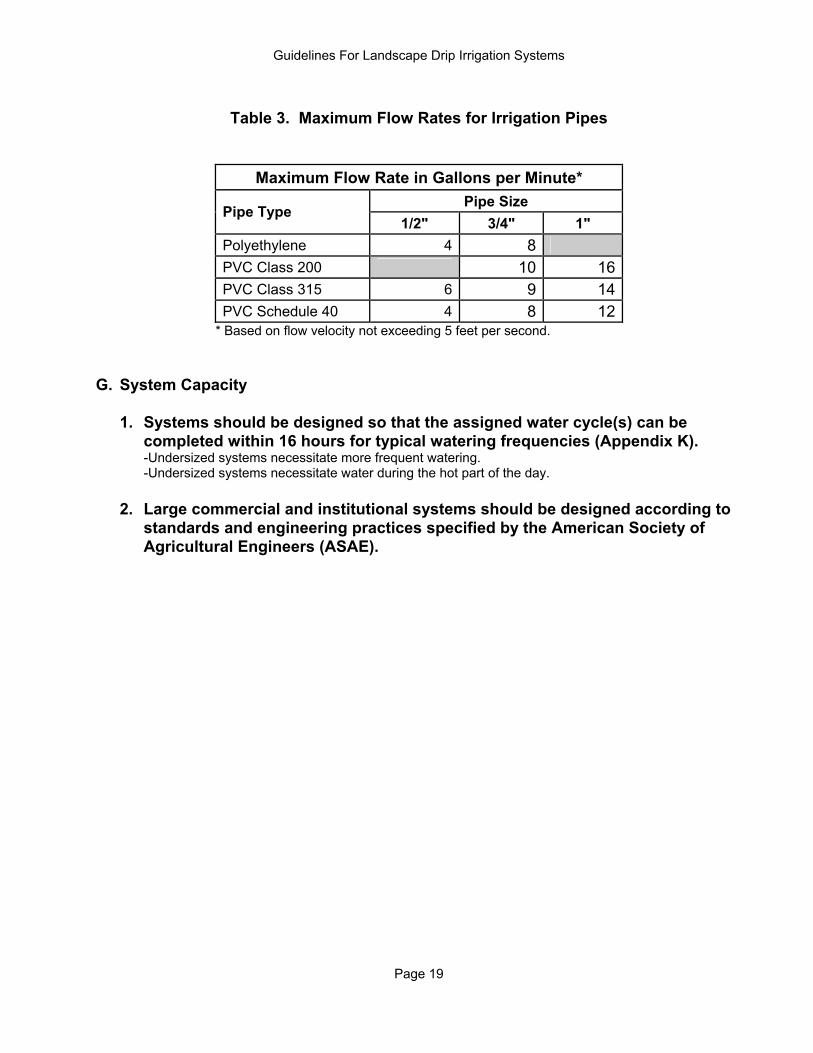
Table 3. Maximum Flow Rates for Irrigation Pipes
Maximum Flow Rate in Gallons per Minute* Pipe Size
Pipe Type 1/2" 3/4" 1"
Polyethylene 4 8 PVC Class 200 10 16 PVC Class 315 6 9 14 PVC Schedule 40 4 8 12
* Based on flow velocity not exceeding 5 feet per second. G. System Capacity
1. Systems should be designed so that the assigned water cycle(s) can be
completed within 16 hours for typical watering frequencies (Appendix K). -Undersized systems necessitate more frequent watering. -Undersized systems necessitate water during the hot part of the day. 2. Large commercial and institutional systems should be designed according to
standards and engineering practices specified by the American Society of Agricultural Engineers (ASAE).
Guidelines For Landscape Drip Irrigation Systems
Page 20
SECTION 4: INSTALLATION Blue Stake Phone Number - Appendix N A. Trenching and Pipe 1. All underground utilities must be located and marked before trenching. Blue
Stake should be called at least two days before digging. - Severing utility lines can cause property damage, personal injury, and even death. - Cutting into utilities necessitates needless repairs, for which you will be required to pay.
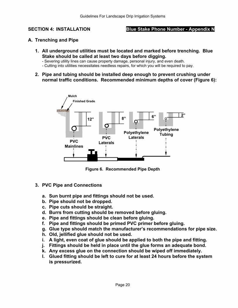
2. Pipe and tubing should be installed deep enough to prevent crushing under
normal traffic conditions. Recommended minimum depths of cover (Figure 6):
12” 8” 6” 2”
PVCMainlines
PVCLaterals
PolyethyleneLaterals
PolyethyleneTubing
Finished GradeMulch
Figure 6. Recommended Pipe Depth
3. PVC Pipe and Connections
a. Sun burnt pipe and fittings should not be used. b. Pipe should not be dropped. c. Pipe cuts should be straight. d. Burrs from cutting should be removed before gluing. e. Pipe and fittings should be clean before gluing. f. Pipe and fittings should be primed PVC primer before gluing. g. Glue type should match the manufacturer’s recommendations for pipe size. h. Old, jellified glue should not be used. i. A light, even coat of glue should be applied to both the pipe and fitting. j. Fittings should be held in place until the glue forms an adequate bond. k. Any excess glue on the connection should be wiped off immediately. l. Glued fitting should be left to cure for at least 24 hours before the system
is pressurized.
Guidelines For Landscape Drip Irrigation Systems
Page 21
4. Polyethylene Pipe and Connections a. Pipe cuts should be straight. b. Pipe and connectors should be matching sizes. - Match brand and size of piping and connectors to ensure proper fit. c. Pipe should not be inserted so deeply into the connector as to restrict flow
through the connection. d. Color coding pipe with spray paint to indicate plant hydrozone is highly
recommended. - Coloring pipe helps identify zones when making repairs. 5. Pressure Testing a. Before backfilling, all pipes and connections should be pressure tested for
leakage. b. Air must be bled out of the system before testing. c. Follow manufacturer’s recommendation for glue curing time before the
system is pressurized (usually 24 hours). B. Flushing 1. Flush backflow preventer before installing valves. 2. Flush valves before installing laterals. - Debris needs to be flushed out of the lines so the equipment does not clog.
3. Flush laterals before installing drip emitters.
Guidelines For Landscape Drip Irrigation Systems
Page 22
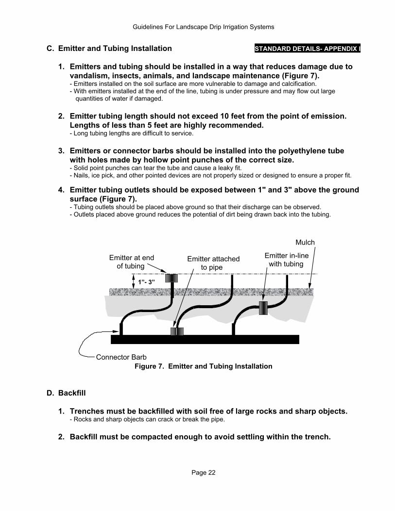
C. Emitter and Tubing Installation STANDARD DETAILS- APPENDIX I 1. Emitters and tubing should be installed in a way that reduces damage due to
vandalism, insects, animals, and landscape maintenance (Figure 7). - Emitters installed on the soil surface are more vulnerable to damage and calcification.
- With emitters installed at the end of the line, tubing is under pressure and may flow out large quantities of water if damaged.
2. Emitter tubing length should not exceed 10 feet from the point of emission.
Lengths of less than 5 feet are highly recommended. - Long tubing lengths are difficult to service. 3. Emitters or connector barbs should be installed into the polyethylene tube
with holes made by hollow point punches of the correct size. - Solid point punches can tear the tube and cause a leaky fit. - Nails, ice pick, and other pointed devices are not properly sized or designed to ensure a proper fit. 4. Emitter tubing outlets should be exposed between 1" and 3" above the ground
surface (Figure 7). - Tubing outlets should be placed above ground so that their discharge can be observed.
- Outlets placed above ground reduces the potential of dirt being drawn back into the tubing.
Emitter at endof tubing
Emitter attachedto pipe
Emitter in-linewith tubing
Connector Barb
1”- 3”
Mulch
Figure 7. Emitter and Tubing Installation
D. Backfill 1. Trenches must be backfilled with soil free of large rocks and sharp objects.
- Rocks and sharp objects can crack or break the pipe. 2. Backfill must be compacted enough to avoid settling within the trench.
Guidelines For Landscape Drip Irrigation Systems
Page 23
SECTION 5: TESTING AND COMPLETION A. At the completion of the project, the contractor should inspect for leaks in
irrigation pipes and connections, ensure that all emitters are operating at their proper flow rate, and ensure all trenches have been properly covered. The backflow preventer should be tested by a certified tester. Backflow preventer testing is mandatory for commercial installations.
B. Actual flow through each valve should be measured. Flow rates should be
written on the as-built map. - Knowledge of proper flow rates is very useful for evaluating how the system is performing later on.
C. The contractor should instruct the buyer on how to program the irrigation
controller and deliver the as-built map, equipment warranties, and operating instructions. Monthly watering schedules should also be supplied.
1. The contractor should provide irrigation controller instructions that
demonstrate the following:
a. Setting current day and time. b. Assigning irrigation schedules to hydrozones. c. Setting watering days.
d. Setting watering cycle start time. e. Setting watering run times.
f. How to adjust watering schedules with the seasons.
2. Legible as-built maps should be provided to the owner. At a minimum, the map should include:
a. Location of point of connection. b. Location of all valves and valve boxes.
c. Location of filters and pressure regulators. d. Location of all mainlines and laterals. e. Location of hydrozones and description of watering method (i.e. sprinklers,
bubblers, drip irrigation, subsurface drip irrigation).
3. A watering schedule for establishment, as well as for the mature landscape, should be provided. The schedule should include:
a. Which hydrozone (valve) is assigned to which watering schedule. b. Watering days. c. Watering cycle start time. d. Hydrozone watering time.
Guidelines For Landscape Drip Irrigation Systems
Page 24
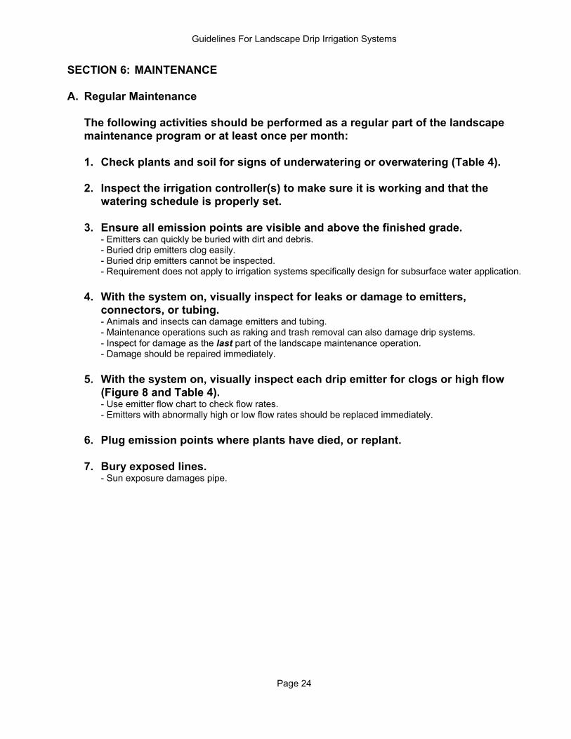
SECTION 6: MAINTENANCE A. Regular Maintenance The following activities should be performed as a regular part of the landscape
maintenance program or at least once per month:
1. Check plants and soil for signs of underwatering or overwatering (Table 4). 2. Inspect the irrigation controller(s) to make sure it is working and that the
watering schedule is properly set. 3. Ensure all emission points are visible and above the finished grade. - Emitters can quickly be buried with dirt and debris. - Buried drip emitters clog easily. - Buried drip emitters cannot be inspected.
- Requirement does not apply to irrigation systems specifically design for subsurface water application. 4. With the system on, visually inspect for leaks or damage to emitters,
connectors, or tubing. - Animals and insects can damage emitters and tubing. - Maintenance operations such as raking and trash removal can also damage drip systems. - Inspect for damage as the last part of the landscape maintenance operation. - Damage should be repaired immediately. 5. With the system on, visually inspect each drip emitter for clogs or high flow
(Figure 8 and Table 4). - Use emitter flow chart to check flow rates. - Emitters with abnormally high or low flow rates should be replaced immediately. 6. Plug emission points where plants have died, or replant. 7. Bury exposed lines. - Sun exposure damages pipe.
Guidelines For Landscape Drip Irrigation Systems
Page 25
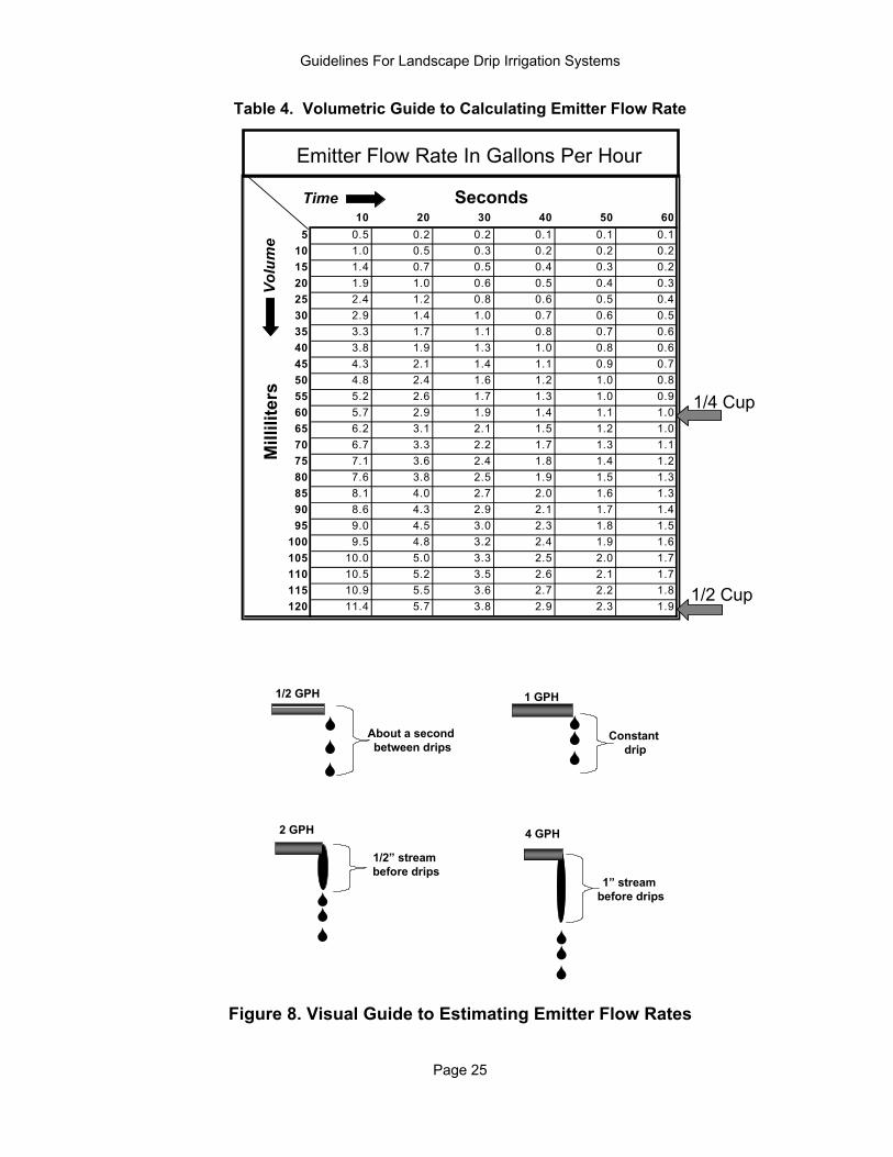
Table 4. Volumetric Guide to Calculating Emitter Flow Rate
10 20 30 40 50 605 0.5 0.2 0.2 0.1 0.1 0.1
10 1.0 0.5 0.3 0.2 0.2 0.215 1.4 0.7 0.5 0.4 0.3 0.220 1.9 1.0 0.6 0.5 0.4 0.325 2.4 1.2 0.8 0.6 0.5 0.430 2.9 1.4 1.0 0.7 0.6 0.535 3.3 1.7 1.1 0.8 0.7 0.640 3.8 1.9 1.3 1.0 0.8 0.645 4.3 2.1 1.4 1.1 0.9 0.750 4.8 2.4 1.6 1.2 1.0 0.855 5.2 2.6 1.7 1.3 1.0 0.960 5.7 2.9 1.9 1.4 1.1 1.065 6.2 3.1 2.1 1.5 1.2 1.070 6.7 3.3 2.2 1.7 1.3 1.175 7.1 3.6 2.4 1.8 1.4 1.280 7.6 3.8 2.5 1.9 1.5 1.385 8.1 4.0 2.7 2.0 1.6 1.390 8.6 4.3 2.9 2.1 1.7 1.495 9.0 4.5 3.0 2.3 1.8 1.5
100 9.5 4.8 3.2 2.4 1.9 1.6105 10.0 5.0 3.3 2.5 2.0 1.7110 10.5 5.2 3.5 2.6 2.1 1.7115 10.9 5.5 3.6 2.7 2.2 1.8120 11.4 5.7 3.8 2.9 2.3 1.9
Volu
me
Time Seconds
Mill
ilite
rs
Emitter Flow Rate In Gallons Per Hour
1/4 Cup
1/2 Cup
1/2 GPH
About a second between drips
1 GPH
Constant drip
2 GPH
1/2” stream before drips
4 GPH
1” stream before drips
Figure 8. Visual Guide to Estimating Emitter Flow Rates
Guidelines For Landscape Drip Irrigation Systems
Page 26
B. Semi-annual Maintenance The following maintenance activities should be performed at least twice per year: 1. Replace batteries in controllers (electronic models). - Controllers can lose the program or revert to default program if power is lost. 2. Ensure all flush valve/cap locations are visible. - Buried flush caps are difficult to find. 3. Ensure valve boxes are visible and can be opened. - Buried valve boxes are difficult to find. 4. Inspect valves, filters, and pressure regulators for damage or leaks. Remove
excess dirt and debris if present in valve box. Check wire splices. 5. Move drip emitters/emission points away from the bases of the plants. In
most cases, emission points should never be closer than one foot from the base of a mature plant. Most of the emission points should be located near the drip line (canopy edge) of the plant.
- Emitters located too close to the base of the plant are often difficult to inspect and repair. - Most of a plant’s water-absorbing roots are near the drip line. - Watering too close to the base of the plant can cause root rot. - Moving emitters away from the base of the plant promotes greater root structural support. C. Annual Maintenance The following maintenance activities should be performed at least once per year*: 1. Clean valve boxes of dirt and debris. 2. Flush filters. A hose can be attached to the flush cap to keep water out of the
valve box. - Debris can be drawn into the system if they are not flushed prior to opening the filter assembly. - Flushing and cleaning may need to be performed more often depending on water characteristics.
3. Inspect and clean filters. Damaged or torn filters should be replaced. - Torn and damaged filters allow debris to enter the system. 4. Flush laterals. - Dirt and debris are drawn into the line are pushed towards the end of the lateral.
- Flushing and cleaning may need to be performed more often depending on water characteristics. 5. Make sure plants have adequate numbers of drip emitters for their size. - Root zones expand as the plants grow.
6. Test PVB and RP backflow preventers (*Required for both commercial and residential system. Enforced for commercial systems). - Backflow prevention helps ensure a pure water supply.
Guidelines For Landscape Drip Irrigation Systems
Page 27
SECTION 7: REPAIR A. The contractor should notify the owner of any major repairs that need to be made. B. Repairs should be made immediately. C. The following procedures should be used for common types of repairs: 1. Clogged emitters a. Drip emitters that cannot be unplugged must be replaced. b. Flush tubing before the emitters are reattached. c. Replace damaged drip emitters with ones of appropriate type and flow rate
(Section 2. N.). d. Replaced and repaired drip emitters should be checked to verify they are
flowing at the proper rate. e. Emitter/tubing connections should be checked for leaks. 2. Malfunctioning (high flow, blown) emitters a. High flow rate drip emitters should be replaced with ones with proper flow
rates. b. Flush tubing before emitters are reattached. c. Replaced emitters should be checked to verify they are flowing at the
proper rate. d. Emitter/tubing connections should be checked for leaks. 3. Broken, torn, or crushed lines a. Dirt and debris should be cleared away from the damaged area before
making repairs. b. Lines should be flushed immediately after the repair is made. c. Repairs should be checked for leaks before backfilling. 4. Leaky emitter or connector barb connections
a. Damaged portion of tubing should be removed and replaced. b. Use goof plugs to seal holes in polyethylene pipe where connectors have
been removed. Tap new holes for the connectors. c. Flush tubing before the emitters are reattached. d. Connections should be checked to ensure they are secure (hold together). e. Repaired connections should be checked for leaks. f. Sections where large numbers of holes need to be tapped should be
replaced with new lateral tubing. 5. Damaged spaghetti distribution tubing a. Damaged tubing should be replaced. b. Clip off end of tubing before replacing emitter. c. Flush tubing before emitters are reattached. d. Tubing and all connections should be checked for leaks before it is buried.
Guidelines For Landscape Drip Irrigation Systems
Page 28
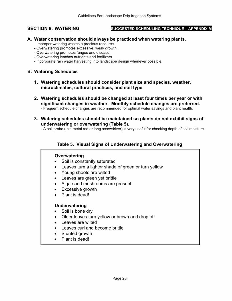
SECTION 8: WATERING SUGGESTED SCHEDULING TECHNIQUE – APPENDIX M A. Water conservation should always be practiced when watering plants. - Improper watering wastes a precious resource. - Overwatering promotes excessive, weak growth. - Overwatering promotes fungus and disease. - Overwatering leaches nutrients and fertilizers. - Incorporate rain water harvesting into landscape design whenever possible. B. Watering Schedules
1. Watering schedules should consider plant size and species, weather,
microclimates, cultural practices, and soil type. 2. Watering schedules should be changed at least four times per year or with
significant changes in weather. Monthly schedule changes are preferred. - Frequent schedule changes are recommended for optimal water savings and plant health.
3. Watering schedules should be maintained so plants do not exhibit signs of
underwatering or overwatering (Table 5). - A soil probe (thin metal rod or long screwdriver) is very useful for checking depth of soil moisture.
Table 5. Visual Signs of Underwatering and Overwatering Overwatering
• Soil is constantly saturated • Leaves turn a lighter shade of green or turn yellow • Young shoots are wilted • Leaves are green yet brittle • Algae and mushrooms are present • Excessive growth • Plant is dead!
Underwatering
• Soil is bone dry • Older leaves turn yellow or brown and drop off • Leaves are wilted • Leaves curl and become brittle • Stunted growth • Plant is dead!
Guidelines For Landscape Drip Irrigation Systems
Page 29
C. Water Requirements RECOMMENDATIONS – APPENDIX J 1. Water requirements should be calculated based upon plant size, plant type,
weather, and microclimates. 2. As plants grow, they should receive more water. - Plants have more leaf area as they grow. - Root zones expand as plants mature. 3. Desert-adapted plants should be watered less than non-desert-adapted plants
of the same size. - Desert plants have natural adaptations that allow them to use less water. D. Watering Frequency RECOMMENDATIONS – APPENDIX K 1. Desert-adapted plants should be watered less frequently than non-desert-
adapted plants of the same size. - Desert plants have natural adaptations that allow them to tolerate low soil moisture. - Desert-adapted plants continue to look good when non-adapted plants are water stressed.
2. Young and transplanted plants should be watered more frequently than
established plants. - Young and transplanted plants do not have established root systems. 3. Once established, smaller plants should be watered more frequently than
larger plants. - Generally, large plants, such as trees, have deeper, more expansive root systems than small plants.
E. Watering Time RECOMMENDATIONS – APPENDIX L
1. Watering times should take into account soil types and slopes. 2. Watering times should be long enough to replenish the entire depth of the root
zone (See figure 3 for typical root depths). 3. Watering times should be short enough to prevent seepage past the root
system. 4. Occasionally run the system with longer run times to leach salts past the root
zones. 5. Watering cycles should be no more than 16 hours per day.
6. Set watering schedule to avoid afternoon watering.
Guidelines For Landscape Drip Irrigation Systems
Page 30
SECTION 9: DEFINITIONS AVB: Atmospheric vacuum breaker. AWWA: American Water Works Association. Backflow: The reverse flow of water from an irrigation system into the potable water source by backpressure or back siphonage. Backflow Prevention Device/Assembly: A safety device used to prevent pollution or contamination of potable water due to backflow. Canopy Diameter: The greatest distance between opposite horizontal edges of the plant. Chemical Injection: The introduction of fertilizers, pesticides, herbicides, growth hormones, amino acids, vitamins, or acids into an irrigation system. Contractor: Any person who engages in the design, fabrication, and installation of an irrigation system on a contractual basis for monetary compensation. Controller: An irrigation timing mechanism. The controller signals the automatic control valves when to open and close on a preset program or based on sensor readings. Consumptive Use: The amount of water used by a plant. Demand depends primarily on plant type, stage of growth, and weather factors. Cycle: One complete run of a controller through all stations on a program. Dielectric: The electrochemical properties of a metal that are responsible for oxidation and reduction. Metals with dissimilar dielectric properties will corrode when in contact with each other. Direct Burial: Any electrical installation including wire and connections placed below the soil grade and not enclosed in waterproof conduit. Distribution Tubing: Small polyethylene tubing (approximately ¼” diameter) that is used to transmit water from emitters or polyethylene supply tubing to the point of emission. Drip Irrigation: The precise low-rate application of water to or beneath the soil surface at the plant root zone. Application normally occurs as discrete or continuous drops between 0.5 to 4 gallons per hour (gph). Emission Uniformity (EU): The comparison of the average flow of 25% of the emitters with the lowest flow rate to the average flow rate of the sample. Emitters: Devices used to control the application of irrigation water. Evapotranspiration (ET) : Water loss from soil and plant tissue. Filter: The assembly of components used to remove suspended solids from irrigation water by screening. Flush: The process of removing debris from the irrigation system by means of flowing water through the filter or the ends of pipes or tubes. Flush Cap/Valve: A device installed at the end of a lateral that can be opened to allow debris to be flushed out of the line. GPH: Gallons per hour. GPM: Gallons per minute.
Guidelines For Landscape Drip Irrigation Systems
Page 31
Hydrozone: A group of emitters that water an area with similar plant types, sun exposures, terrain, soil types, and microclimates. Irrigation: Application of water by artificial means. Landscape: Any area that is ornamentally planted including, but not limited to: turf, groundcover, flowers, shrubs, trees, and similar plant materials. Lateral: The water delivery pipeline that supplies water to the emitters from a remote control valve. Loam Soil: A soil containing less than 40% clay and more than 20% sand. Loam usually has a mixture of sand, silt, and clay. Mainline: A pipeline that carries water from the water source to the remote control valves. Mesh: The number of strands per inch in a filter. Micro Sprinklers: Emitters that apply water through a miniature rotating assembly or orifice. ml: Milliliter. Multi-Port Emitters: A manifold of two or more emitters encased in a single unit. Operating Pressure: The nominal or average pressure at which the components of an irrigation system operate. Potable Water: Water that is suitable for human consumption. PVB: Pressure Vacuum Breaker. PVC: Poly vinyl chloride. Remote Control Valve: A valve in an irrigation system activated automatically by a controller through hydraulic or electrical signal lines. Root Zone: The volume of soil in which a plant's roots are actively involved in water absorption. RP: Reduced pressure principle backflow preventer. Runoff: Any situation where the water application rate is greater than the soil infiltration rate causing water to move across the soil away from the intended point of application. Solvent Weld: A PVC pipe connection made by chemically melting one fitting into another. Submain: A pipeline between a remote control valve and a lateral. Supply Tubing: Polyethylene pipe that is typically ½” to ¾” in diameter. UL: Underwriters Laboratory. UV: Ultraviolet light. Vacuum Relief Valve: A valve designed to allow air into a pipe when it drains.
Guidelines For Landscape Drip Irrigation Systems
Page 32
SECTION 10: REFERENCES American Society of Agricultural Engineers (ASAE). Engineering Practices, ASAE EP405: Design, installation and performance of trickle irrigation systems. American Water Works Association (AWWA). Manual of Cross Connection Control. University of Southern California. Arizona Meteorological Network (AZMET). http://ag.arizona.edu/azmet Center for Irrigation Technology (CIT). Irrigation Equipment Performance Report: Drip Emitters and Micro Sprinklers. California State University, Fresno. 1993. Florida Irrigation Society. Standards and Specification for Turf and Landscape Irrigation Systems, Second Edition, November 1989. Hung, Joseph Y. T. and Dave Koo, Determination of Emitter Spacing and Run Time for Maximum Water Use Efficiency. Irrigation Association 1993 International Trade Show and Technical Conference. San Diego, California. Jensen, et. al., Design and Operation of Farm Irrigation Systems. ASAE Monograph Number 3, American Society of Agricultural Engineers, September 1983. Irrigation Training and Research Center, Landscape Water Management Principles, Version 1.01. California Polytechnic State University. Rainbird Sprinkler Corporation, Landscape Irrigation Products 1999 – 2000. September 1998. The Arizona Chapter of the American Society of Irrigation Consultants. Minimum Standards for Landscape Irrigation. The Toro Company, Drip Irrigation Design for Landscaping. Riverside, California, September 1990. Tipton, Jimmy L., "A Brief Review of Roots." Southwest Horticulture. July/August 1991.
Guidelines For Landscape Drip Irrigation Systems
Page 33
APPENDIX A
STANDARD INSTALLATION DETAIL FOR IRRIGATION CONTROLLERS
Junction Box Controller
Sch 80 PVC Conduitfor 24 Volt Wire
Valve Control Wires12” Minimum DepthWide Sweep Elbow
Conduit For 110 Volt Wire
Circuit Breaker Box
Note:Protect Controller FromDirect Sunlight
Grounding Rod
To Plumbing
Ground Wires
Hot
Neu
tral
Gro
und
from
Con
trol
ler
To G
roun
d
DedicatedBreaker
Wiring Example
*
*
Note: 110 volt electric work shall be done by a licensed electrician.
Guidelines For Landscape Drip Irrigation Systems
Page 34
APPENDIX B
STANDARD INSTALLATION DETAILS FOR LOW VOLTAGE WIRE SPLICES
Direct Bury Connector
Wire Nut
Grease-FilledCapsule
Insert NutDeeply Into Grease
Snap Lid Closed
Dry Splice Connector
Capsule Filled with Waterproof Gel
Wires Crimped
Waterproof Gel
Water-Proof Wire Nut
Twist Wires Like RegularWire Nut
Expansion Coils
Wrap 6 - 8 times around 3/4” PVC Pipe
Guidelines For Landscape Drip Irrigation Systems
Page 35
APPENDIX C
STANDARD INSTALLATION DETAILS AND EXAMPLES FOR POINTS OF CONNECTION
BeforeInstallation
Hose Bibb
House Shut Off Valve
Service Line From Meter
AfterInstallation
Irrigation Shut Off Valve
House Shut Off Valve
Backflow Preventer
Union
Hose Bibb
Mainline To Irrigation Valves
Service Line From Meter
Guidelines For Landscape Drip Irrigation Systems
Page 36
APPENDIX D
STANDARD INSTALLATION DETAILS FOR BACKFLOW PREVENTION ASSEMBLIES
PressureRegulator
Wye Filter withBlowout Valve
AtmosphericVacuumBreaker
Schedule 80 PVC
Polyethylene Tubing
PVC Coupling
PVC/Poly Adapter
WaterproofConnectors
ExpansionCoils
SolenoidValve
UV resistant wire ties
12”
Min
imum
6” -
12”
Abo
ve
high
est p
oint
in ir
rigat
ed z
one
Run Minimum of 12”of Sch. 80 PVC Pipe
Away from Elbow
FinishedGrade
Sch. 80 PVC Union(Optional)
Atmospheric Vacuum Breaker (Combination Assembly)
Guidelines For Landscape Drip Irrigation Systems
Page 37
APPENDIX D
STANDARD INSTALLATION DETAILS FOR BACKFLOW PREVENTION ASSEMBLIES
Pressure Vacuum Breaker
Guidelines For Landscape Drip Irrigation Systems
Page 38
APPENDIX D
STANDARD INSTALLATION DETAILS FOR BACKFLOW PREVENTION ASSEMBLIES
Reduced Pressure Principle Backflow Preventer
Guidelines For Landscape Drip Irrigation Systems
Page 39
APPENDIX E
STANDARD INSTALLATION DETAILS FOR VALVE BOXES, VALVES, FILTERS, AND PRESSURE REGULATORS
Valve Box
Guidelines For Landscape Drip Irrigation Systems
Page 40
APPENDIX E
STANDARD INSTALLATION DETAILS FOR VALVE BOXES, VALVES, FILTERS, AND PRESSURE REGULATORS
Valve, Filter, and Pressure Reducer
Guidelines For Landscape Drip Irrigation Systems
Page 41
APPENDIX F
STANDARD INSTALLATION DETAILS FOR FLUSH CAPS AND FLUSH VALVES
Flush Cap
Guidelines For Landscape Drip Irrigation Systems
Page 42
APPENDIX F
STANDARD INSTALLATION DETAILS FOR FLUSH CAPS AND FLUSH VALVES
Flush Valve
Guidelines For Landscape Drip Irrigation Systems
Page 43
APPENDIX G
EMITTER PLACEMENT EXAMPLES
Loop at Installation
Same Loop at Maturity
Original root ball
Canopy at planting
Emitters placed formature canopy
Move emission pointsaway from base of plant
Mature canopy
Loop Design
Guidelines For Landscape Drip Irrigation Systems
Page 44
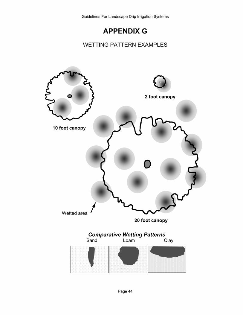
APPENDIX G
WETTING PATTERN EXAMPLES
.
2 foot canopy
.
10 foot canopy
20 foot canopy
Sand Loam ClayComparative Wetting Patterns
Wetted area
Guidelines For Landscape Drip Irrigation Systems
Page 45
APPENDIX H
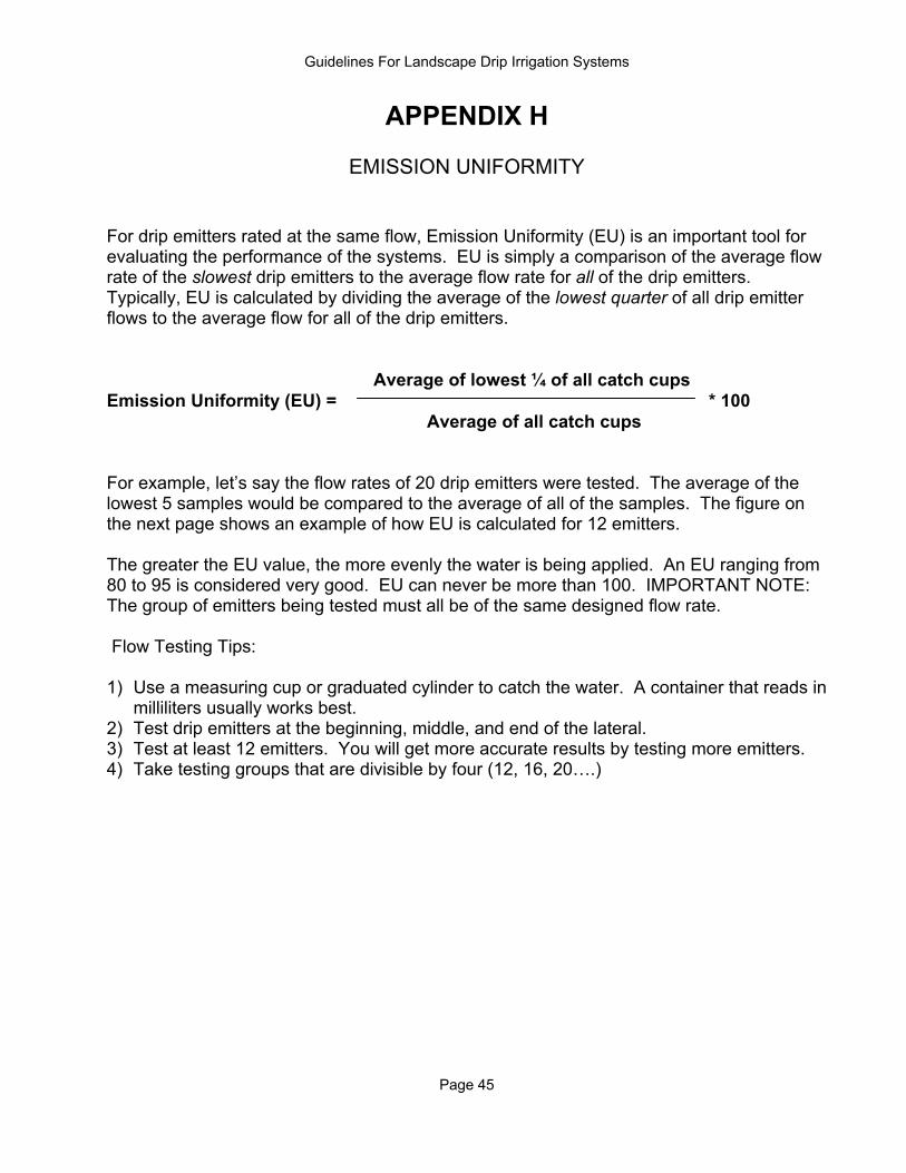
EMISSION UNIFORMITY For drip emitters rated at the same flow, Emission Uniformity (EU) is an important tool for evaluating the performance of the systems. EU is simply a comparison of the average flow rate of the slowest drip emitters to the average flow rate for all of the drip emitters. Typically, EU is calculated by dividing the average of the lowest quarter of all drip emitter flows to the average flow for all of the drip emitters. Average of lowest ¼ of all catch cups Emission Uniformity (EU) = * 100 Average of all catch cups For example, let’s say the flow rates of 20 drip emitters were tested. The average of the lowest 5 samples would be compared to the average of all of the samples. The figure on the next page shows an example of how EU is calculated for 12 emitters. The greater the EU value, the more evenly the water is being applied. An EU ranging from 80 to 95 is considered very good. EU can never be more than 100. IMPORTANT NOTE: The group of emitters being tested must all be of the same designed flow rate. Flow Testing Tips: 1) Use a measuring cup or graduated cylinder to catch the water. A container that reads in
milliliters usually works best. 2) Test drip emitters at the beginning, middle, and end of the lateral. 3) Test at least 12 emitters. You will get more accurate results by testing more emitters. 4) Take testing groups that are divisible by four (12, 16, 20….)
Guidelines For Landscape Drip Irrigation Systems
Page 46
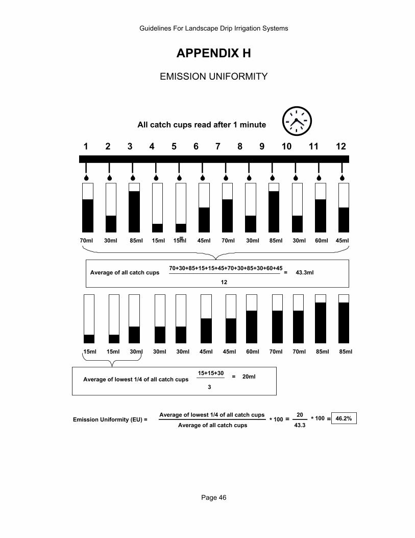
APPENDIX H
EMISSION UNIFORMITY
1 2 3 4 5 6 7 8 9 10 11 12
70ml 30ml 85ml 15ml 15ml 45ml 70ml 30ml 85ml 30ml 60ml 45ml
70+30+85+15+15+45+70+30+85+30+60+45
1243.3ml=
70ml30ml 85ml15ml 15ml 45ml 70ml30ml 85ml30ml 60ml45ml
Average of all catch cups
Average of lowest 1/4 of all catch cups15+15+30
3
= 20ml
Emission Uniformity (EU) =Average of all catch cups
Average of lowest 1/4 of all catch cups =
=
100*43.3
20 100* 46.2%=
All catch cups read after 1 minute
Guidelines For Landscape Drip Irrigation Systems
Page 47
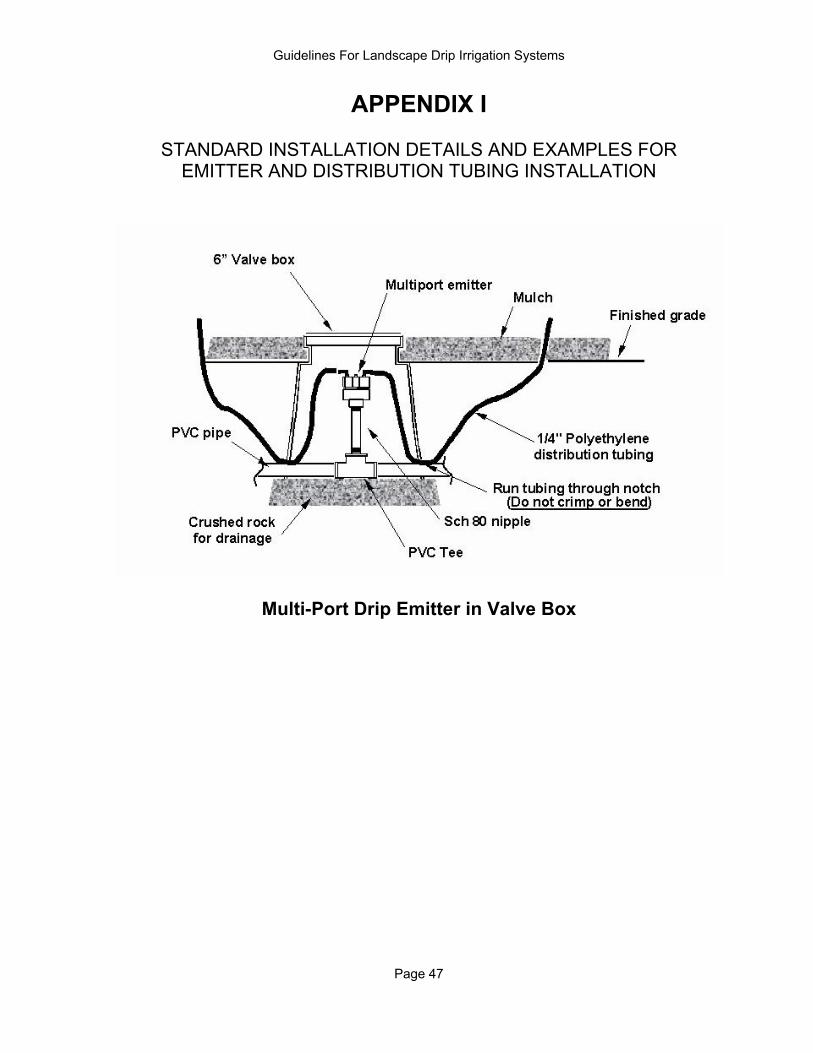
APPENDIX I
STANDARD INSTALLATION DETAILS AND EXAMPLES FOR EMITTER AND DISTRIBUTION TUBING INSTALLATION
Multi-Port Drip Emitter in Valve Box
Guidelines For Landscape Drip Irrigation Systems
Page 48
APPENDIX I
STANDARD INSTALLATION DETAILS AND EXAMPLES FOR EMITTER AND DISTRIBUTION TUBING INSTALLATION
Multi-Port Drip Emitter in Soil
Guidelines For Landscape Drip Irrigation Systems
Page 49
APPENDIX J
ESTIMATED WATER REQUIREMENTS FOR PHOENIX, ARIZONA*
Plant Coeffic ient 0.15 Eto
Months (In./Day) 1 2 3 4 5 6 7 8January 0.08 0.01 0.01 0.02 0.03 0.04 0.04 0.05 0.06 February 0.12 0.01 0.02 0.03 0.04 0.06 0.07 0.08 0.09 March 0.18 0.02 0.03 0.05 0.07 0.08 0.10 0.12 0.13 April 0.26 0.02 0.05 0.07 0.10 0.12 0.15 0.17 0.19 May 0.31 0.03 0.06 0.09 0.12 0.14 0.17 0.20 0.23 June 0.35 0.03 0.07 0.10 0.13 0.16 0.20 0.23 0.26 July 0.33 0.03 0.06 0.09 0.12 0.15 0.19 0.22 0.25 August 0.29 0.03 0.05 0.08 0.11 0.14 0.16 0.19 0.22 September 0.25 0.02 0.05 0.07 0.09 0.12 0.14 0.16 0.19 October 0.18 0.02 0.03 0.05 0.07 0.08 0.10 0.12 0.13 November 0.11 0.01 0.02 0.03 0.04 0.05 0.06 0.07 0.08 December 0.07 0.01 0.01 0.02 0.03 0.03 0.04 0.05 0.05 Examples: Native Prickly Pear, Cereus, Saguaro, ChollaIMPORTANT NOTE: This table should only be used as a guide. It does not take into account rainfall, m icroclimates, weather extremes, and cultural requirements. It also assumes the plants are not deciduous.
Canopy Area (Square Feet)Typical Water Usage - Gallons Per Day
Cactus
Plant Coefficient 0.30
1 2 3 4 5 6 7 8 9 10 15 20 25Eto
Months (In./Day) 1 3 7 13 20 28 38 50 64 79 177 314 491 January 0.08 0.01 0.05 0.1 0.2 0.3 0.4 0.6 0.8 1.0 1.2 2.6 4.7 7.3 February 0.12 0.02 0.07 0.2 0.3 0.4 0.6 0.9 1.1 1.4 1.8 4.0 7.0 11.0 March 0.18 0.03 0.11 0.2 0.4 0.7 1.0 1.3 1.7 2.1 2.6 5.9 10.6 16.5 April 0.26 0.04 0.15 0.3 0.6 1.0 1.4 1.9 2.4 3.1 3.8 8.6 15.3 23.9 May 0.31 0.05 0.18 0.4 0.7 1.1 1.6 2.2 2.9 3.7 4.6 10.2 18.2 28.4 June 0.35 0.05 0.21 0.5 0.8 1.3 1.8 2.5 3.3 4.2 5.1 11.6 20.6 32.1 July 0.33 0.05 0.19 0.4 0.8 1.2 1.7 2.4 3.1 3.9 4.8 10.9 19.4 30.3 August 0.29 0.04 0.17 0.4 0.7 1.1 1.5 2.1 2.7 3.4 4.3 9.6 17.0 26.6 September 0.25 0.04 0.15 0.3 0.6 0.9 1.3 1.8 2.3 3.0 3.7 8.3 14.7 22.9 October 0.18 0.03 0.11 0.2 0.4 0.7 1.0 1.3 1.7 2.1 2.6 5.9 10.6 16.5 November 0.11 0.02 0.06 0.1 0.3 0.4 0.6 0.8 1.0 1.3 1.6 3.6 6.5 10.1 December 0.07 0.01 0.04 0.1 0.2 0.3 0.4 0.5 0.7 0.8 1.0 2.3 4.1 6.4 Examples: Bur-sage, Cassia, Texas Ranger, Brittlebush, Mesquite, Palo Verde, Sweet Acacia IMPORTANT NOTE: This table should only be used as a guide. It does not take into account rainfall, microclimates, weather extremes, and cultural requirements. It also assumes the plants are not deciduous.
Typical Water Usage - Gallons Per DayCanopy Diameter (Feet)
Area (Square Feet)
Desert Adapted Plants, Natives
*Note: Derived from monthly average evapotranspiration values from Phoenix area Arizona Meteorological Network (AZMET) weather
stations. Evapotranspiration derived by modified Penman method.
Guidelines For Landscape Drip Irrigation Systems
Page 50
APPENDIX J
ESTIMATED WATER REQUIREMENTS FOR PHOENIX, ARIZONA*
Plant Coeff icient 0.45
1 2 3 4 5 6 7 8 9 10 15 20 25Eto
Months (In./Day) 1 3 7 13 20 28 38 50 64 79 177 314 491 January 0.08 0.02 0.07 0.2 0.3 0.4 0.6 0.9 1.1 1.4 1.8 4.0 7.0 11.0 February 0.12 0.03 0.11 0.2 0.4 0.7 1.0 1.3 1.7 2.1 2.6 5.9 10.6 16.5 March 0.18 0.04 0.16 0.4 0.6 1.0 1.4 1.9 2.5 3.2 4.0 8.9 15.9 24.8 April 0.26 0.06 0.23 0.5 0.9 1.4 2.1 2.8 3.7 4.6 5.7 12.9 22.9 35.8 May 0.31 0.07 0.27 0.6 1.1 1.7 2.5 3.3 4.4 5.5 6.8 15.4 27.3 42.7 June 0.35 0.08 0.31 0.7 1.2 1.9 2.8 3.8 4.9 6.2 7.7 17.3 30.8 48.2 July 0.33 0.07 0.29 0.7 1.2 1.8 2.6 3.6 4.7 5.9 7.3 16.3 29.1 45.4 August 0.29 0.06 0.26 0.6 1.0 1.6 2.3 3.1 4.1 5.2 6.4 14.4 25.5 39.9 September 0.25 0.06 0.22 0.5 0.9 1.4 2.0 2.7 3.5 4.5 5.5 12.4 22.0 34.4 October 0.18 0.04 0.16 0.4 0.6 1.0 1.4 1.9 2.5 3.2 4.0 8.9 15.9 24.8 November 0.11 0.02 0.10 0.2 0.4 0.6 0.9 1.2 1.6 2.0 2.4 5.4 9.7 15.1 December 0.07 0.02 0.06 0.1 0.2 0.4 0.6 0.8 1.0 1.2 1.5 3.5 6.2 9.6 Examples: Natal Plum, Mexican Bird of Paradise, Lantana, Ruellia, SissooIMPORTANT NOTE: This table should only be used as a guide. It does not take into account rainfall, microclimates, weather extremes, and cultural requirements. It also assumes the plants are not deciduous.
Typical Water Usage - Gallons Per DayCanopy Diameter (Feet)
Area (Square Feet)
Moderate Water Use Plants
Plant Coefficient 0.65
1 2 3 4 5 6 7 8 9 10 15 20 25Eto
Months (In./Day) 1 3 7 13 20 28 38 50 64 79 177 314 491 January 0.08 0.6 0.9 1.2 1.6 2.1 2.5 5.7 10.2 15.9 February 0.12 1.0 1.4 1.9 2.4 3.1 3.8 8.6 15.3 23.9 March 0.18 1.4 2.1 2.8 3.7 4.6 5.7 12.9 22.9 35.8 April 0.26 2.1 3.0 4.1 5.3 6.7 8.3 18.6 33.1 51.7 May 0.31 2.5 3.5 4.8 6.3 8.0 9.9 22.2 39.4 61.6 June 0.35 2.8 4.0 5.5 7.1 9.0 11.1 25.0 44.5 69.6 July 0.33 2.6 3.8 5.1 6.7 8.5 10.5 23.6 42.0 65.6 August 0.29 2.3 3.3 4.5 5.9 7.5 9.2 20.8 36.9 57.6 September 0.25 2.0 2.9 3.9 5.1 6.4 8.0 17.9 31.8 49.7 October 0.18 1.4 2.1 2.8 3.7 4.6 5.7 12.9 22.9 35.8 November 0.11 0.9 1.3 1.7 2.2 2.8 3.5 7.9 14.0 21.9 December 0.07 0.6 0.8 1.1 1.4 1.8 2.2 5.0 8.9 13.9 Examples: Citrus, Peach, PlumIMPORTANT NOTE: This table should only be used as a guide. It does not take into account rainfall, microclimates, weather extremes, and cultural requirements. It also assumes the plants are not deciduous.
Typical Water Usage - Gallons Per DayCanopy Diameter (Feet)
Area (Square Feet)
Fruit Trees
*Note: Derived from monthly average evapotranspiration values from Phoenix area Arizona Meteorological Network (AZMET) weather stations. Evapotranspiration derived by modified Penman method.

Guidelines For Landscape Drip Irrigation Systems
Page 51
APPENDIX J
ESTIMATED WATER REQUIREMENTS FOR PHOENIX, ARIZONA*
Plant Coef f ic ient 0.70
1 2 3 4 5 6 7 8 9 10 15 20 25Eto
Months (In./Day) 1 3 7 13 20 28 38 50 64 79 177 314 491 January 0.08 0.03 0.11 0.2 0.4 0.7 1.0 1.3 1.8 2.2 2.7 6.2 11.0 17.1 February 0.12 0.04 0.16 0.4 0.7 1.0 1.5 2.0 2.6 3.3 4.1 9.2 16.4 25.7 March 0.18 0.06 0.25 0.6 1.0 1.5 2.2 3.0 3.9 5.0 6.2 13.9 24.7 38.5 April 0.26 0.09 0.36 0.8 1.4 2.2 3.2 4.4 5.7 7.2 8.9 20.0 35.6 55.7 May 0.31 0.11 0.42 1.0 1.7 2.7 3.8 5.2 6.8 8.6 10.6 23.9 42.5 66.4 June 0.35 0.12 0.48 1.1 1.9 3.0 4.3 5.9 7.7 9.7 12.0 27.0 48.0 74.9 July 0.33 0.11 0.45 1.0 1.8 2.8 4.1 5.5 7.2 9.2 11.3 25.4 45.2 70.6 August 0.29 0.10 0.40 0.9 1.6 2.5 3.6 4.9 6.4 8.0 9.9 22.3 39.7 62.1 September 0.25 0.09 0.34 0.8 1.4 2.1 3.1 4.2 5.5 6.9 8.6 19.3 34.3 53.5 October 0.18 0.06 0.25 0.6 1.0 1.5 2.2 3.0 3.9 5.0 6.2 13.9 24.7 38.5 November 0.11 0.04 0.15 0.3 0.6 0.9 1.4 1.8 2.4 3.1 3.8 8.5 15.1 23.5 December 0.07 0.02 0.10 0.2 0.4 0.6 0.9 1.2 1.5 1.9 2.4 5.4 9.6 15.0 Examples: Hibiscus, Rose, Jasmine, Cottonwood, Ash, MulberryIMPORTANT NOTE: This table should only be used as a guide. It does not take into account rainfall, microclimates, weather extremes, and cultural requirements. It also assumes the plants are not deciduous.
Typical Water Usage - Gallons Per DayCanopy Diameter (Feet)
Area (Square Feet)
High Water Use Plants
Plant Coef f ic ient 0.85 Eto
Months (In./Day) 0.5 1 2 3 4 5 6 7 8 9 10 11 12 January 0.08 0.02 0.04 0.1 0.1 0.2 0.2 0.3 0.3 0.3 0.4 0.4 0.5 0.5 February 0.12 0.03 0.06 0.1 0.2 0.3 0.3 0.4 0.4 0.5 0.6 0.6 0.7 0.8 March 0.18 0.05 0.10 0.2 0.3 0.4 0.5 0.6 0.7 0.8 0.9 1.0 1.0 1.1 April 0.26 0.07 0.14 0.3 0.4 0.6 0.7 0.8 1.0 1.1 1.2 1.4 1.5 1.7 May 0.31 0.08 0.16 0.3 0.5 0.7 0.8 1.0 1.1 1.3 1.5 1.6 1.8 2.0 June 0.35 0.09 0.19 0.4 0.6 0.7 0.9 1.1 1.3 1.5 1.7 1.9 2.0 2.2 July 0.33 0.09 0.17 0.3 0.5 0.7 0.9 1.0 1.2 1.4 1.6 1.7 1.9 2.1 August 0.29 0.08 0.15 0.3 0.5 0.6 0.8 0.9 1.1 1.2 1.4 1.5 1.7 1.8 September 0.25 0.07 0.13 0.3 0.4 0.5 0.7 0.8 0.9 1.1 1.2 1.3 1.5 1.6 October 0.18 0.05 0.10 0.2 0.3 0.4 0.5 0.6 0.7 0.8 0.9 1.0 1.0 1.1 November 0.11 0.03 0.06 0.1 0.2 0.2 0.3 0.3 0.4 0.5 0.5 0.6 0.6 0.7 December 0.07 0.02 0.04 0.1 0.1 0.1 0.2 0.2 0.3 0.3 0.3 0.4 0.4 0.4 Examples: Annual Flowers, Garden VegetablesIMPORTANT NOTE: This table should only be used as a guide. It does not take into account rainfall, microclimates, weather extremes, and cultural requirements. It also assumes the plants are not deciduous.
Typical Water Usage - Gallons Per DayArea (Square Feet)
Very High Water Use Plants
*Note: Derived from monthly average evapotranspiration values from Phoenix area Arizona Meteorological Network (AZMET) weather stations. Evapotranspiration derived by modified Penman method.

Guidelines For Landscape Drip Irrigation Systems
Page 52
APPENDIX J
ESTIMATED WATER REQUIREMENTS FOR TUCSON, ARIZONA*
Plant Coeffic ient 0.15 Eto
Months (In./Day) 1 2 3 4 5 6 7 8January 0.09 0.01 0.02 0.03 0.03 0.04 0.05 0.06 0.07 February 0.13 0.01 0.02 0.04 0.05 0.06 0.07 0.08 0.10 March 0.19 0.02 0.04 0.05 0.07 0.09 0.11 0.12 0.14 April 0.27 0.02 0.05 0.07 0.10 0.12 0.15 0.17 0.20 May 0.32 0.03 0.06 0.09 0.12 0.15 0.18 0.21 0.24 June 0.36 0.03 0.07 0.10 0.13 0.17 0.20 0.23 0.27 July 0.30 0.03 0.06 0.09 0.11 0.14 0.17 0.20 0.23 August 0.26 0.02 0.05 0.07 0.10 0.12 0.15 0.17 0.20 September 0.24 0.02 0.05 0.07 0.09 0.11 0.14 0.16 0.18 October 0.19 0.02 0.04 0.05 0.07 0.09 0.11 0.12 0.14 November 0.12 0.01 0.02 0.03 0.04 0.06 0.07 0.08 0.09 December 0.08 0.01 0.02 0.02 0.03 0.04 0.05 0.05 0.06 Examples: Native Prick ly Pear, Cereus, Saguaro, ChollaIMPORTANT NOTE: This table should only be used as a guide. It does not take into account rainfall, microclimates, weather extremes, and cultural requirements. It also assumes the plants are not deciduous.
Typical Water Usage - Gallons Per Day Canopy Area (Square Feet)
Cactus
Plant Coef f ic ient 0.30
1 2 3 4 5 6 7 8 9 10 15 20 25Eto
Months (In./Day) 1 3 7 13 20 28 38 50 64 79 177 314 491 January 0.09 0.01 0.05 0.1 0.2 0.3 0.5 0.6 0.8 1.1 1.3 3.0 5.3 8.3 February 0.13 0.02 0.08 0.2 0.3 0.5 0.7 0.9 1.2 1.5 1.9 4.2 7.5 11.8 March 0.19 0.03 0.11 0.3 0.4 0.7 1.0 1.4 1.8 2.3 2.8 6.3 11.2 17.5 April 0.27 0.04 0.16 0.4 0.6 1.0 1.4 1.9 2.5 3.2 3.9 8.8 15.7 24.5 May 0.32 0.05 0.19 0.4 0.7 1.2 1.7 2.3 3.0 3.8 4.6 10.4 18.6 29.0 June 0.36 0.05 0.21 0.5 0.8 1.3 1.9 2.6 3.4 4.2 5.2 11.8 20.9 32.7 July 0.30 0.04 0.18 0.4 0.7 1.1 1.6 2.2 2.8 3.6 4.5 10.0 17.8 27.8 August 0.26 0.04 0.15 0.3 0.6 1.0 1.4 1.9 2.5 3.1 3.8 8.6 15.3 24.0 September 0.24 0.04 0.14 0.3 0.6 0.9 1.3 1.8 2.3 2.9 3.6 8.0 14.3 22.3 October 0.19 0.03 0.11 0.3 0.4 0.7 1.0 1.4 1.8 2.3 2.8 6.3 11.2 17.5 November 0.12 0.02 0.07 0.2 0.3 0.4 0.6 0.9 1.1 1.4 1.8 4.0 7.0 11.0 December 0.08 0.01 0.05 0.1 0.2 0.3 0.4 0.6 0.8 1.0 1.2 2.7 4.7 7.4 Examples: Bursage, Cassia, Texas Ranger, Brittle Bush, Mesquite, Palo Verde, Sweet Acacia IMPORTANT NOTE: This table should only be used as a guide. It does not take into account rainfall, microclimates, weather extremes, and cultural requirements. It also assumes the plants are not deciduous.
Desert Adapted Plants, NativesTypical Water Usage - Gallons Per Day
Canopy Diameter (Feet)
Area (Square Feet)
*Note: Derived from monthly average evapotranspiration values from Tucson area Arizona Meteorological Network (AZMET) weather stations. Evapotranspiration derived by modified Penman method.
Guidelines For Landscape Drip Irrigation Systems
Page 53
APPENDIX J
ESTIMATED WATER REQUIREMENTS FOR TUCSON, ARIZONA*
Plant Coef f ic ient 0.45
1 2 3 4 5 6 7 8 9 10 15 20 25Eto
Months (In./Day) 1 3 7 13 20 28 38 50 64 79 177 314 491 January 0.09 0.02 0.08 0.2 0.3 0.5 0.7 1.0 1.3 1.6 2.0 4.5 8.0 12.4 February 0.13 0.03 0.11 0.3 0.5 0.7 1.0 1.4 1.8 2.3 2.8 6.4 11.3 17.7 March 0.19 0.04 0.17 0.4 0.7 1.0 1.5 2.1 2.7 3.4 4.2 9.4 16.8 26.2 April 0.27 0.06 0.23 0.5 0.9 1.5 2.1 2.9 3.8 4.8 5.9 13.2 23.5 36.7 May 0.32 0.07 0.28 0.6 1.1 1.7 2.5 3.4 4.5 5.6 7.0 15.7 27.8 43.5 June 0.36 0.08 0.31 0.7 1.3 2.0 2.8 3.8 5.0 6.4 7.9 17.7 31.4 49.1 July 0.30 0.07 0.27 0.6 1.1 1.7 2.4 3.3 4.3 5.4 6.7 15.0 26.7 41.7 August 0.26 0.06 0.23 0.5 0.9 1.4 2.1 2.8 3.7 4.7 5.8 12.9 23.0 36.0 September 0.24 0.05 0.21 0.5 0.9 1.3 1.9 2.6 3.4 4.3 5.4 12.1 21.4 33.5 October 0.19 0.04 0.17 0.4 0.7 1.0 1.5 2.1 2.7 3.4 4.2 9.4 16.8 26.2 November 0.12 0.03 0.11 0.2 0.4 0.7 1.0 1.3 1.7 2.1 2.6 5.9 10.6 16.5 December 0.08 0.02 0.07 0.2 0.3 0.4 0.6 0.9 1.1 1.4 1.8 4.0 7.1 11.1 Examples: Natal P lum, Mexican Bird of Paradise, Lantana, Ruellia, S issooIMPORTANT NOTE: This table should only be used as a guide. It does not take into account rainfall, microclimates, weather extremes, and cultural requirements. It also assumes the plants are not deciduous.
Moderate Water Use PlantsTypical Water Usage - Gallons Per Day
Canopy Diameter (Feet)
Area (Square Feet)
Plant Coef f ic ient 0.65
1 2 3 4 5 6 7 8 9 10 15 20 25Eto
Months (In./Day) 1 3 7 13 20 28 38 50 64 79 177 314 491 January 0.09 0.7 1.0 1.4 1.8 2.3 2.9 6.5 11.5 18.0 February 0.13 1.0 1.5 2.0 2.6 3.3 4.1 9.2 16.4 25.6 March 0.19 1.5 2.2 3.0 3.9 4.9 6.1 13.6 24.2 37.8 April 0.27 2.1 3.1 4.2 5.4 6.9 8.5 19.1 33.9 53.0 May 0.32 2.5 3.6 4.9 6.4 8.1 10.1 22.6 40.2 62.8 June 0.36 2.8 4.1 5.6 7.3 9.2 11.3 25.5 45.4 70.9 July 0.30 2.4 3.5 4.7 6.2 7.8 9.6 21.7 38.6 60.3 August 0.26 2.1 3.0 4.1 5.3 6.7 8.3 18.7 33.2 51.9 September 0.24 1.9 2.8 3.8 5.0 6.3 7.7 17.4 31.0 48.4 October 0.19 1.5 2.2 3.0 3.9 4.9 6.1 13.6 24.2 37.8 November 0.12 1.0 1.4 1.9 2.4 3.1 3.8 8.6 15.3 23.9 December 0.08 0.6 0.9 1.3 1.6 2.1 2.6 5.8 10.3 16.0 Examples: Citrus, Peach, PlumIMPORTANT NOTE: This table should only be used as a guide. It does not take into account rainfall, microclimates, weather extremes, and cultural requirements. It also assumes the plants are not deciduous.
Fruit T reesTypical Water Usage - Gallons Per Day
Canopy Diameter (Feet)
Area (Square Feet)
*Note: Derived from monthly average evapotranspiration values from Tucson area Arizona Meteorological Network (AZMET) weather stations. Evapotranspiration derived by modified Penman method.
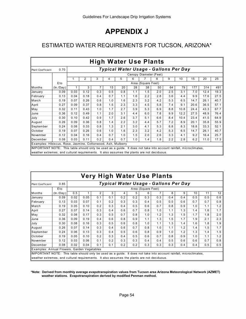
Guidelines For Landscape Drip Irrigation Systems
Page 54
APPENDIX J
ESTIMATED WATER REQUIREMENTS FOR TUCSON, ARIZONA*
Plant Coef f ic ient 0.70
1 2 3 4 5 6 7 8 9 10 15 20 25Eto
Months (In./Day) 1 3 7 13 20 28 38 50 64 79 177 314 491 January 0.09 0.03 0.12 0.3 0.5 0.8 1.1 1.5 2.0 2.5 3.1 7.0 12.4 19.3 February 0.13 0.04 0.18 0.4 0.7 1.1 1.6 2.2 2.8 3.6 4.4 9.9 17.6 27.5 March 0.19 0.07 0.26 0.6 1.0 1.6 2.3 3.2 4.2 5.3 6.5 14.7 26.1 40.7 April 0.27 0.09 0.37 0.8 1.5 2.3 3.3 4.5 5.8 7.4 9.1 20.6 36.5 57.1 May 0.32 0.11 0.43 1.0 1.7 2.7 3.9 5.3 6.9 8.8 10.8 24.4 43.3 67.7 June 0.36 0.12 0.49 1.1 2.0 3.1 4.4 6.0 7.8 9.9 12.2 27.5 48.9 76.4 July 0.30 0.10 0.42 0.9 1.7 2.6 3.7 5.1 6.6 8.4 10.4 23.4 41.5 64.9 August 0.26 0.09 0.36 0.8 1.4 2.2 3.2 4.4 5.7 7.2 8.9 20.1 35.8 55.9 September 0.24 0.08 0.33 0.8 1.3 2.1 3.0 4.1 5.3 6.8 8.3 18.8 33.3 52.1 October 0.19 0.07 0.26 0.6 1.0 1.6 2.3 3.2 4.2 5.3 6.5 14.7 26.1 40.7 November 0.12 0.04 0.16 0.4 0.7 1.0 1.5 2.0 2.6 3.3 4.1 9.2 16.4 25.7 December 0.08 0.03 0.11 0.2 0.4 0.7 1.0 1.4 1.8 2.2 2.8 6.2 11.0 17.3 Examples: Hibiscus, Rose, Jasmine, Cottonwood, Ash, MulberryIMPORTANT NOTE: This table should only be used as a guide. It does not take into account rainfall, microclimates, weather extremes, and cultural requirements. It also assumes the plants are not deciduous.
High Water Use PlantsTypical Water Usage - Gallons Per Day
Canopy Diameter (Feet)
Area (Square Feet)
Plant Coef f ic ient 0.85 Eto
Months (In./Day) 0.5 1 2 3 4 5 6 7 8 9 10 11 12 January 0.09 0.02 0.05 0.1 0.1 0.2 0.2 0.3 0.3 0.4 0.4 0.5 0.5 0.6 February 0.13 0.03 0.07 0.1 0.2 0.3 0.3 0.4 0.5 0.5 0.6 0.7 0.7 0.8 March 0.19 0.05 0.10 0.2 0.3 0.4 0.5 0.6 0.7 0.8 0.9 1.0 1.1 1.2 April 0.27 0.07 0.14 0.3 0.4 0.6 0.7 0.8 1.0 1.1 1.3 1.4 1.6 1.7 May 0.32 0.08 0.17 0.3 0.5 0.7 0.8 1.0 1.2 1.3 1.5 1.7 1.8 2.0 June 0.36 0.09 0.19 0.4 0.6 0.8 0.9 1.1 1.3 1.5 1.7 1.9 2.1 2.3 July 0.30 0.08 0.16 0.3 0.5 0.6 0.8 1.0 1.1 1.3 1.4 1.6 1.8 1.9 August 0.26 0.07 0.14 0.3 0.4 0.6 0.7 0.8 1.0 1.1 1.2 1.4 1.5 1.7 September 0.24 0.06 0.13 0.3 0.4 0.5 0.6 0.8 0.9 1.0 1.2 1.3 1.4 1.5 October 0.19 0.05 0.10 0.2 0.3 0.4 0.5 0.6 0.7 0.8 0.9 1.0 1.1 1.2 November 0.12 0.03 0.06 0.1 0.2 0.3 0.3 0.4 0.4 0.5 0.6 0.6 0.7 0.8 December 0.08 0.02 0.04 0.1 0.1 0.2 0.2 0.3 0.3 0.3 0.4 0.4 0.5 0.5 Examples: Annual Flowers, Garden VegetablesIMPORTANT NOTE: This table should only be used as a guide. It does not take into account rainfall, microclimates, weather extremes, and cultural requirements. It also assumes the plants are not deciduous.
Very High Water Use PlantsTypical Water Usage - Gallons Per Day
Area (Square Feet)
*Note: Derived from monthly average evapotranspiration values from Tucson area Arizona Meteorological Network (AZMET) weather stations. Evapotranspiration derived by modified Penman method.
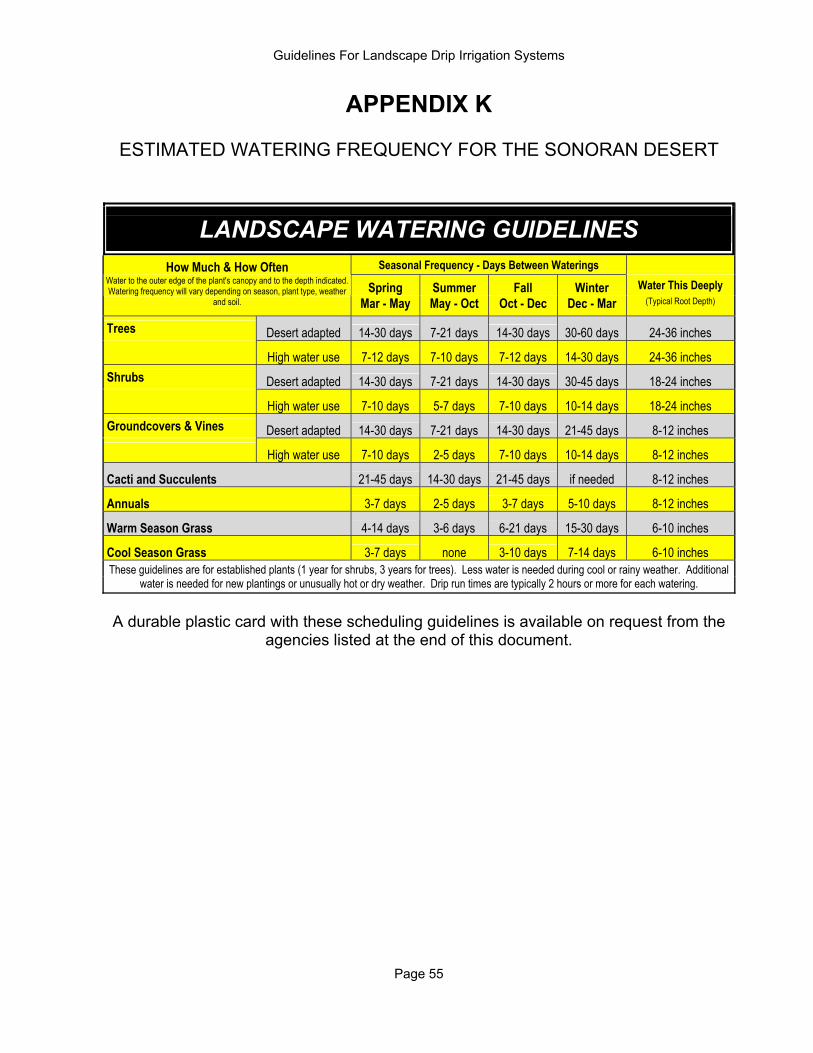
Guidelines For Landscape Drip Irrigation Systems
Page 55
APPENDIX K
ESTIMATED WATERING FREQUENCY FOR THE SONORAN DESERT
LANDSCAPE WATERING GUIDELINES
How Much & How Often Seasonal Frequency - Days Between Waterings
Spring Summer Fall Winter Water This Deeply Water to the outer edge of the plant's canopy and to the depth indicated. Watering frequency will vary depending on season, plant type, weather
and soil. Mar - May May - Oct Oct - Dec Dec - Mar (Typical Root Depth)
Trees Desert adapted 14-30 days 7-21 days 14-30 days 30-60 days 24-36 inches
High water use 7-12 days 7-10 days 7-12 days 14-30 days 24-36 inches Shrubs Desert adapted 14-30 days 7-21 days 14-30 days 30-45 days 18-24 inches
High water use 7-10 days 5-7 days 7-10 days 10-14 days 18-24 inches Groundcovers & Vines Desert adapted 14-30 days 7-21 days 14-30 days 21-45 days 8-12 inches High water use 7-10 days 2-5 days 7-10 days 10-14 days 8-12 inches
Cacti and Succulents 21-45 days 14-30 days 21-45 days if needed 8-12 inches
Annuals 3-7 days 2-5 days 3-7 days 5-10 days 8-12 inches
Warm Season Grass 4-14 days 3-6 days 6-21 days 15-30 days 6-10 inches
Cool Season Grass 3-7 days none 3-10 days 7-14 days 6-10 inches These guidelines are for established plants (1 year for shrubs, 3 years for trees). Less water is needed during cool or rainy weather. Additional
water is needed for new plantings or unusually hot or dry weather. Drip run times are typically 2 hours or more for each watering.
A durable plastic card with these scheduling guidelines is available on request from the
agencies listed at the end of this document.

Guidelines For Landscape Drip Irrigation Systems
Page 56
APPENDIX L
RECOMMENDED MAXIMUM WATERING TIME TO PREVENT DEEP SEEPAGE
Em itte rDepth Flow Ra te Sandy Sandy loam Loam Clay loam Silty clay Clay1 Foot 1 gph 1.4 2.3 3.8 5.1 10.3 7.2
Groundcover 2 gph 1.1 1.9 3.1 4.2 8.5 5.9Small shrubs 4 gph 0.9 1.5 2.6 3.5 7.0 4.8
2 Fee t 1 gph 4.2 6.8 11.5 15.4 31.1 21.6Shrubs 2 gph 3.4 5.6 9.5 12.6 25.5 17.7
Small trees 4 gph 2.8 4.6 7.8 10.4 20.9 14.53 Fee t 1 gph 7.9 13.0 22.0 29.3 59.1 41.0Trees 2 gph 6.5 10.7 18.0 24.1 48.5 33.7
4 gph 5.3 8.7 14.8 19.7 39.8 27.6
Watering Time in HoursSoil Type
Typical Phoenix and Tucson soils
Watering times are based on the volume of soil that can be saturated from 60% available moisture content. These values should only be used as guidelines for establishing maximum watering times to avoid seepage past the root zone. Perhaps the best technique for determining maximum run times is to physically measure depth of soil moisture with a soil probe or thin rod. In most desert soils, a probe easily penetrates through the saturated depth. The saturated depth, however, is about one-half the total depth the moisture will reach. For example, a saturated depth of six inches means 12 inches will eventually be moistened. Measure the saturated depth directly under the drip emitter to calculate the total depth of moisture in the soil. The system should not run any longer than it takes to moisten (not saturate) the root depth.
Saturated Depth
Moistened Depth
Probe
Drip systems should occasionally be run for longer periods to flush salts out of the root zone. To prevent salt buildup, a common practice is to water twice the normal watering time once or twice per year.
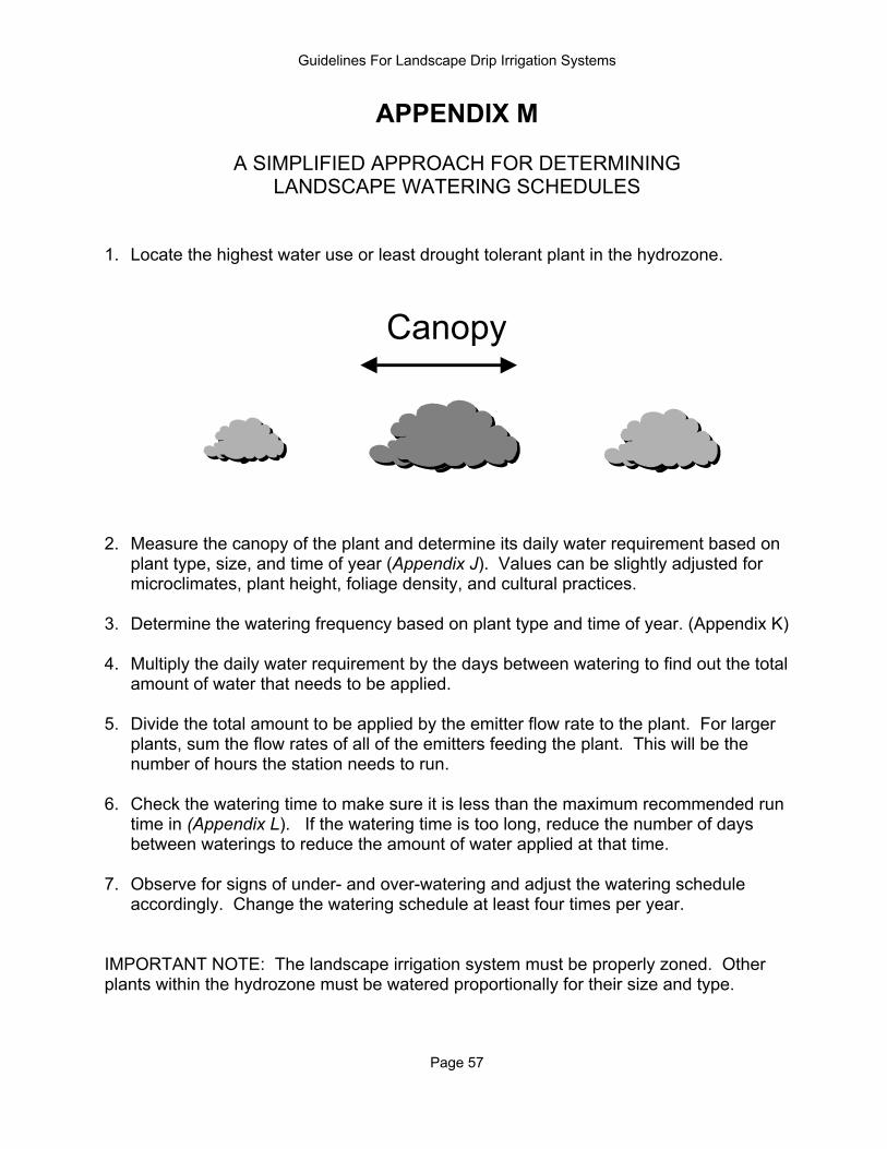
Guidelines For Landscape Drip Irrigation Systems
Page 57
APPENDIX M
A SIMPLIFIED APPROACH FOR DETERMINING LANDSCAPE WATERING SCHEDULES
1. Locate the highest water use or least drought tolerant plant in the hydrozone.
Canopy
2. Measure the canopy of the plant and determine its daily water requirement based on
plant type, size, and time of year (Appendix J). Values can be slightly adjusted for microclimates, plant height, foliage density, and cultural practices.
3. Determine the watering frequency based on plant type and time of year. (Appendix K) 4. Multiply the daily water requirement by the days between watering to find out the total
amount of water that needs to be applied. 5. Divide the total amount to be applied by the emitter flow rate to the plant. For larger
plants, sum the flow rates of all of the emitters feeding the plant. This will be the number of hours the station needs to run.
6. Check the watering time to make sure it is less than the maximum recommended run
time in (Appendix L). If the watering time is too long, reduce the number of days between waterings to reduce the amount of water applied at that time.
7. Observe for signs of under- and over-watering and adjust the watering schedule
accordingly. Change the watering schedule at least four times per year. IMPORTANT NOTE: The landscape irrigation system must be properly zoned. Other plants within the hydrozone must be watered proportionally for their size and type.
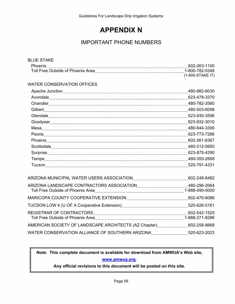
Guidelines For Landscape Drip Irrigation Systems
Page 58
APPENDIX N
IMPORTANT PHONE NUMBERS BLUE STAKE
Phoenix 602-263-1100 Toll Free Outside of Phoenix Area 1-800-782-5348 (1-800-STAKE IT)
WATER CONSERVATION OFFICES
Apache Junction 480-982-6030 Avondale 623-478-3370 Chandler 480-782-3580 Gilbert 480-503-6098 Glendale 623-930-3596 Goodyear 623-932-3010 Mesa 480-644-3306 Peoria 623-773-7286 Phoenix 602-261-8367 Scottsdale 480-312-5650 Surprise 623-875-4290 Tempe 480-350-2668 Tucson 520-791-4331
ARIZONA MUNICIPAL WATER USERS ASSOCIATION 602-248-8482
ARIZONA LANDSCAPE CONTRACTORS ASSOCIATION 480-296-2064 Toll Free Outside of Phoenix Area 1-888-490-0000
MARICOPA COUNTY COOPERATIVE EXTENSION 602-470-8086
TUCSON LOW 4 (U OF A Cooperative Extension) 520-626-5161
REGISTRAR OF CONTRACTORS 602-542-1525 Toll Free Outside of Phoenix Area 1-888-271-9286
AMERICAN SOCIETY OF LANDSCAPE ARCHITECTS (AZ Chapter) 602-258-8668
WATER CONSERVATION ALLIANCE OF SOUTHERN ARIZONA 520-623-2023
Note: This complete document is available for download from AMWUA’s Web site,
www.amwua.org.
Any official revisions to this document will be posted on this site.