Embed Size (px)
Citation preview

Guidelines for Earthquake-Resistant Construction of Non-Engineered Rural and Sub Urban Houses
in Pakistan
Prepared by:
Version 1 21 April 2006

Guidelines for Earthquake-Resistant Construction of Houses in Pakistan
2
With financial support
UN-HABITAT

Guidelines for Earthquake-Resistant Construction of Houses in Pakistan
i
PREFACE

Guidelines for Earthquake-Resistant Construction of Houses in Pakistan
ii
TABLE OF CONTENTS
PREFACE .................................................................................................................................................................... I
1 INTRODUCTION .............................................................................................................................................. 1
1.1 OBJECTIVES AND AIM ................................................................................................................................. 1
1.2 TARGET AUDIENCE ..................................................................................................................................... 2
1.3 SCOPE AND LIMITATION .............................................................................................................................. 3
2 BUILDING CONSTRUCTION PRACTICES IN PAKISTAN ..................................................................... 4
2.1 SEISMIC HAZARD AND RISK OF PAKISTAN................................................................................................... 4
2.2 PREVAILING BUILDING CONSTRUCTION PRACTICE ...................................................................................... 7
3 BASIC CONCEPTS OF EARTHQUAKE-RESISTANT CONSTRUCTION ........................................... 12
3.1 BASIC FACTORS CONTRIBUTING TO SEISMIC SAFETY OF BUILDINGS .......................................................... 12
3.2 EARTHQUAKE-RESISTING FEATURES FOR RURAL MASONRY HOUSES ...................................................... 12
3.3 APPROPRIATE CONSTRUCTION MATERIALS ............................................................................................... 13
4 SITE SELECTION .......................................................................................................................................... 14
4.1 CONSIDERATIONS FOR SITE SELECTION ...................................................................................................... 14
4.2 APPROPRIATE SITE FOR CONSTRUCTION .................................................................................................... 17
4.3 IMPROVEMENT OF SITE .............................................................................................................................. 17
4.4 IMPROVEMENT IN FOUNDATION ................................................................................................................. 20
5 APPROPRIATE CONFIGURATION ........................................................................................................... 21
5.1 PLAN SHAPE .............................................................................................................................................. 21
5.2 SHORT WALLS ........................................................................................................................................... 22
5.3 L-SHAPED BUILDING .................................................................................................................................. 22
5.4 BOX EFFECT .............................................................................................................................................. 23
5.5 CLOSE BUILDING ....................................................................................................................................... 23
6 STONE MASONRY HOUSE ......................................................................................................................... 24
6.1 DIFFERENT TYPES OF STONE MASONRY HOUSES ...................................................................................... 24

Guidelines for Earthquake-Resistant Construction of Houses in Pakistan
iii
6.2 MAIN FACTORS FOR ACHIEVING SEISMIC SAFETY IN STONE MASONRY HOUSES .......................................... 24
6.3 CONSTRUCTION OF STONE MASONRY HOUSE ........................................................................................... 25
7 TIMBER HOUSE ............................................................................................................................................ 42
7.1 DIFFERENT TYPES OF WOODEN WALL CONSTRUCTION .............................................................................. 42
7.2 JOINTS IN WOOD FRAMES .......................................................................................................................... 44
7.3 FOUNDATION OF WOODEN HOUSE ............................................................................................................ 44
8 BRICK AND BLOCK MASONRY HOUSE ................................................................................................. 47
8.1 MAIN FACTORS FOR ACHIEVING SEISMIC SAFETY IN BRICK / BLOCK MASONRY HOUSES ............................ 47
8.2 CONSTRUCTION OF BRICK MASONRY HOUSE IN MUD OR CEMENT MORTAR ............................................ 48
8.3 CONSTRUCTION OF BLOCK MASONRY BUILDINGS .................................................................................... 62
8.4 FLOOR/ROOF CONSTRUCTION FOR MASONRY HOUSES ............................................................................... 66
9 REINFORCED CONCRETE BUILDINGS .................................................................................................. 72
9.1 FOUNDATION ............................................................................................................................................. 72
9.2 BEAM ........................................................................................................................................................ 73
9.3 COLUMN .................................................................................................................................................... 75
9.4 BEAM COLUMN JOINT ............................................................................................................................... 76
9.5 RC SLAB ................................................................................................................................................... 77
9.6 QUALITY OF CONCRETE ............................................................................................................................. 78
10 REPAIR AND STRENGTHENING OF EXISTING BUILDINGS ............................................................ 80
10.1 ASSESSMENT OF BUILDING DAMAGE.......................................................................................................... 80
10.2 REPAIR AND STRENGTHENING ................................................................................................................... 81
REFERENCES .......................................................................................................................................................... 89

Guidelines for Earthquake-Resistant Construction of Houses in Pakistan
1
1 INTRODUCTION
An earthquake of Magnitude 7.6 hit northern areas of Pakistan particularly the states of Azad Jammu and Kashmir (AJK) and North West Frontier Province (NWFP) on 8 Oct. 2005. The earthquake shaking caused massive destruction to houses, public buildings and other critical structures in Pakistan. Reports confirm the death of more than 70,000 people and damage and destruction of more than 400,000 houses. Most of the damaged / destroyed houses were constructed with mud, stone or brick masonry in mud mortar with katcha roof or CGI sheet roofing. These buildings were damaged mainly due to poor quality of construction such as absence of through stones in stone masonry, no proper bonding between two orthogonal walls, lack of proper connection between floor / roof and the supporting walls; and because almost all of the buildings do not posses any earthquake-resistant elements in them. No earthquake risk was considered at all in design, construction and maintenance of these buildings.
After such a huge destruction, people and the authorities are now concerned about the reconstruction of houses. Even, some of the communities have already started reconstruction works on their own. This is now the right time to work towards promoting earthquake safer construction. Therefore, this guideline is prepared to provide required knowledge on earthquake-resistant construction of non-engineered rural and sub-urban houses and to facilitate concerned stakeholders on such construction practices.
1.1 OBJECTIVES AND AIM
The main objective of this guideline is to promote and facilitate earthquake-resistant construction practices in the rural and sub urban areas of Pakistan by providing necessary concept and know-how suitable for local construction workers and communities. Following are additional objectives of this guideline:
• Provide basic concepts as well as construction details for earthquake-resistant construction of mostly prevailing building typologies in rural and sub urban areas;
• Promote earthquake-resistant construction using locally available materials;
• Identify and promote local wisdom and indigenous knowledge for earthquake safer construction, if there is any;
• Provide technical reference to the technicians as well as to the authorities for promoting earthquake safer construction through training and awareness programs. It will give a basis for training and capacity buildings programs.

Guidelines for Earthquake-Resistant Construction of Houses in Pakistan
2
1.2 TARGET AUDIENCE
This publication is specifically designed for providing necessary technical guidance to the local construction workers and to the common people. It is expected that the “Urdu” version of this publication can easily be understood and used by these target groups. In addition, this guideline is also meant for providing technical reference to the technical professionals ranging from engineers, sub-engineers to the field technicians in design, construction as well as strengthening of earthquake damaged buildings. This will also provide a technical manual for training local construction workers, social mobilizers and even common people for the earthquake-resistant construction of houses. Following table summarizes the intended use of this guideline by different target audiences:
Table 1: Target Audience and Intended use of the Guideline
Target Audience Possible use of this guideline
Local construction workers (masons, carpenters, bar-benders)
• Technical manual for construction – “Urdu” version will be most appropriate for this target group
Local builders, petty contractors • Technical manual for construction – “Urdu” version will be most appropriate for this target group
Common people • Technical source book for construction - “Urdu” version will be most appropriate for this target group
Lead masons, master trainers • Training manual
Technical professionals (engineers, sub-engineers, technicians)
• Technical reference for design, construction and strengthening of non-engineered rural and sub-urban houses
• Training manual for conducting training programs targeting construction workers and common people
Trainers, Master trainers, social mobilizers
• Training manual
• Reference material for awareness programs, campaigns
The following key considerations formed the basis to design this work:
• Primary focus is community-initiated building • Focus is to follow simple methods/techniques to build earthquake resistant houses • Priority is on non-engineered construction practice

Guidelines for Earthquake-Resistant Construction of Houses in Pakistan
3
1.3 SCOPE AND LIMITATION
This Guideline focuses on earthquake safer construction of mostly prevailing non-engineered houses made with stone, brick and block in mud mortar or cement mortar and also tries to cover the RCC construction that are prevailing in rural and sub urban areas. This guideline is mainly for enhancing the seismic safety of residential houses and does not cover more important and public buildings like schools, health centers etc. It is advised to construct schools and other important buildings with higher level of seismic safety using the suitable standards for such structures. The guidelines suggest such strengthening schemes that deliberately minimize the use of more expensive materials in order to keep the cost of earthquake resistance to a minimum. Moreover, the advise and recommendations presented here can be used as good practice for other than residential houses also, although, special attention should be paid to the need of some variation in details that may be required by the importance of such buildings and specifics of the designs.
Further, this guideline is prepared for enhancing the seismic safety of non-engineered buildings located in the seismic prone areas. The concepts and construction details suggested in this guideline are meant for improving the seismic safety of such buildings which lie under the moderate to high seismic areas. In the areas where the seismicity is lower, some of the suggested measures could be omitted as mentioned in each of the corresponding sections. However, it is strongly advised that providing all the measures mentioned in this guideline will enhance seismic performance of buildings significantly.

Guidelines for Earthquake-Resistant Construction of Houses in Pakistan
4
2 BUILDING CONSTRUCTION PRACTICES IN PAKISTAN
2.1 SEISMIC HAZARD AND RISK OF PAKISTAN
Pakistan lies at the subduction zone of Indian Plate to the Eurasian Plate and houses Hindukush and Himalayan Range of mountains. The tectonic movement in the subduction zone is making the entire region including Pakistan seismically very active. Hence, Pakistan is an earthquake prone country, north and western belt of the country being highly seismic. Most earthquakes of the past are concentrated in these belts; one of the most notable earthquakes in the recent history is Quetta earthquake of 1935 which lies in the south-western part of the country. Figure 1 shows the seismicity of Pakistan.
Seismic Hazard map prepared by USGS (Figure 2) also suggests that the seismic hazard of north and eastern belts of Pakistan is very high as compared to its other parts. Figure 2 also shows the probable peak ground acceleration in different parts of the country.
Figure 1: Seismcity of Pakistan (earthquake records of 1990 – 2000) (Source: USGS)

Guidelines for Earthquake-Resistant Construction of Houses in Pakistan
5
The entire area of Pakistan is divided into four major zones from earthquake hazard point of view. This seismic zoning map of Pakistan is presented in Figure 3.
Figure 2: Seismic Hazard Map of Pakistan (Source: USGS)
(Peak Ground Acceleration (m/s2) with 10% Probability of Exceedance in 50 Years)
Pakistan
Afghanistan
India

Guidelines for Earthquake-Resistant Construction of Houses in Pakistan
6
Figure 3: Seismic Zoning Map of Pakistan (Source: Geological Survey of Pakistan)

Guidelines for Earthquake-Resistant Construction of Houses in Pakistan
7
2.2 PREVAILING BUILDING CONSTRUCTION PRACTICE
2.2.1 Main structural system / walling material
Following major types of construction are prevailing in rural and sub-urban areas of Pakistan:
A. Mud wall construction (earthen construction)
This type of construction mainly prevails in north and north-western rural areas. There are three major types of earthen construction: Hand packed mud wall, Sun dried brick (adobe) wall and Rammed earth wall construction. Seismic capacity of such houses being very low, earthen house is not recommended for highly seismic areas. Therefore these houses are not dealt in this guideline. However, the seismic performance of such houses can also be improved significantly by applying the earthquake-resistant techniques described in this guideline for other types of masonry houses.
B. Stone Masonry Wall
Figure 4: A typical mud wall house
Figure 5: Random rubble masonry house in mud mortar

Guidelines for Earthquake-Resistant Construction of Houses in Pakistan
8
C. Block wall construction
Figure 6: Dressed stone masonry in cement mortar
Figure 7: Block wall construction in cement mortar

Guidelines for Earthquake-Resistant Construction of Houses in Pakistan
9
D. Brick wall construction
E. Timber Building
(Timber frame with timber/stone/brick infill)
Figure 8: Brick wall construction in cement mortar
Figure 9: Timber House

Guidelines for Earthquake-Resistant Construction of Houses in Pakistan
10
F. RCC construction
2.2.2 Flooring / roofing system
A. Mud floor / roof over system of timber members
Figure 10: Atypical non-engineered RCC Frame building
Figure 11: A typical mud floor over timber members

Guidelines for Earthquake-Resistant Construction of Houses in Pakistan
11
B. CGI sheet roofing
C. Reinforced concrete/brick slab
Figure 12: CGI sheet roofing over timber structures
Figure 13: Concrete slab floor and roof

Guidelines for Earthquake-Resistant Construction of Houses in Pakistan
12
3 BASIC CONCEPTS OF EARTHQUAKE-RESISTANT CONSTRUCTION
3.1 BASIC FACTORS CONTRIBUTING TO SEISMIC SAFETY OF BUILDINGS
3.2 EARTHQUAKE-RESISTING FEATURES FOR RURAL MASONRY HOUSES
Following are the main elements to be incorporated in a house to make it stronger and more resistant to earthquakes:
1. Horizontal Bands at different levels
2. Corner strengthening with stitches
►Proper site selection: The proper site selection is very important for stable and disaster safe construction.
►Appropriate planning: The shape, size and proportion of a building is important for its seismic safety.
►Good foundation resting on a Firm Base: The quality of foundation and the base on which the foundation rests are equally important for the safety of a building.
►The building has to act as a single unit for a good earthquake resistance: This can be achieved by incorporating following elements in the construction of a building:
− Vertical reinforcement: − Horizontal bands well connected to the vertical reinforcements and embedded in masonry − Diagonal bracing (horizontal and vertical) − Lateral restraints
►Better bonding within masonry: The type and quality of bond within the walling units is the main contributor to the integrity and strength of the walls.
►Controlled size and location of openings: Large un-stiffened openings create soft story effect leading to a deformation of building during an earthquake. To prevent such effects the opening size and location has to be controlled.
►Light construction: The lighter structures absorbs less earthquake force and hence less effect. Lighter materials like timber, bamboo, straw is preferred provided they are available.
►Use of appropriate construction materials: Burn Brick, Boulder stone, quarry stone; cement or appropriate mud mortar, solid block, Stabilized soil blocks, treated wood.

Guidelines for Earthquake-Resistant Construction of Houses in Pakistan
13
3. Vertical Reinforcement
4. Tying floor/roof rigidly with lateral load resisting elements (walls / columns)
5. Diagonal Bracing
3.3 APPROPRIATE CONSTRUCTION MATERIALS
The following should be used as general guidelines for selecting appropriate construction materials for different building construction types. More detailed guidelines for selecting appropriate materials are given in the corresponding sections for different building construction types.
Brick: Over-burnt, under-burnt and deformed bricks should be avoided.
Boulder stone: Round boulders, unlike angular ones, do not provide uniform binding when used in wall construction, resulting in movement of individual boulders and ultimate failure of the wall during earthquake shaking. Therefore, round boulders should be avoided, or broken into angular pieces before being laid.
Quarry stones: Easily breakable soft stones should be avoided. Only solid and strong quarry stones with no obvious fractures should be used.
Mud Mortar: Mud for mortar should be free from organic materials. It should also be free from pebbles and other hard materials which will upset the mortar thickness. Dry mud should be thoroughly kneaded with water to prepare a dense paste. Property of mud is discussed in the following sections.
Wood: Wood is used in door/window, for corner strengthening, and also for the roof.. Treated wood should be preferred to the untreated ones.

Guidelines for Earthquake-Resistant Construction of Houses in Pakistan
14
4 SITE SELECTION
Site for building construction should be selected carefully. Site should be stable and safe enough to withstand the building load. Hazardous areas should be avoided for building construction to minimize risks against natural disasters. Site Investigations help in identifying existence of any potential hazard such as sliding, erosion, land subsidence or liquefaction. However, detail investigation of each site in rural and sub-urban areas is not feasible and affordable. Therefore, general site investigation is recommended and the local practice for addressing any local hazard should also be identified, judged and applied. Following points are considered to be helpful for selecting appropriate site for buildings construction.
4.1 CONSIDERATIONS FOR SITE SELECTION
4.1.1 Steep and unstable slopes
Building should not be constructed near or on steep and unstable slopes. Steep slopes made of soft or crumbly rock, clayey loam or deposits materials are not stable and may easily fall down during earthquake shaking or even in normal time or during rainfalls. Also, higher damages to buildings have been observed near or on steep slopes during earthquakes due to shaking amplification. Therefore, such steep slopes should be avoided.
4.1.2 Areas susceptible to landslides and rockfall
Landslides or rock fall areas should be avoided while selecting a site for building construction. In normal times, the slopes may look stable, but slope failure could be triggered by an earthquake. Landslides can completely wash out the building. Rock fall (Figure 8) can damage buildings partially or completely. However, building in these
Figure 14: Potential hazard at steep slopes (Source: Anti-seismic construction handbook, CRATerre)

Guidelines for Earthquake-Resistant Construction of Houses in Pakistan
15
areas can be constructed after providing proper precaution by retaining walls and green barriers. Simple indication of sustained stability of a slope is the existence of upright standing trees on it. Abnormally inclined trees on a slope indicate instability of the hill slope.
4.1.3 Filled area:
Building should not be constructed on un-compacted filled ground. In a filled ground, the bearing capacity of foundation sub-soil would be very low and settlement of foundation may occur. Also, foundation may be exposed in due course of time due to easy scouring of the filled up soil. If a building has to be constructed on a filled ground, its foundation should be deep enough so as to rest on firm ground surface below the fill.
4.1.4 River banks:
River banks are susceptible to frequent flooding (Figure 16), scouring and also susceptible to liquefaction during earthquakes. Buildings should be far enough from the
Figure 14: Potential landslide hazard (Source: CRA TERRE - Anti-seismic construction handbook)
Figure 15: A rock fall area

Guidelines for Earthquake-Resistant Construction of Houses in Pakistan
16
flooding zone of river. Construction in such areas should be undertaken only after carrying out necessary river protection works.
Figure 16: Flood Hazard due to proximity to River
4.1.5 Water logged area:
In water logged areas, building may face a variety of problems such as flooding, foundation settlement and liquefaction. Construction of buildings on loose sand and soft clay should be avoided. In case the building is to be constructed in a water logged area, sufficient drainage should be provided by constructing drainage-ditches; or the ground level of the building should be raised by making a plinth of compacted earth, or the house should be built on stilt.
4.1.6 Geological fault and Ruptured areas
Buildings should not be constructed within 500 m of the surface trace of an active fault or any ruptured areas in order to avoid fault-rupture hazard. The area on either side of the fault trace could be developed as recreational park, farm, orchard etc
4.1.7 Trees
Buildings should not be constructed close to any big tree. Roots of the tree may penetrate into the foundation and damage the whole building. Also, if a building is near to a big tree, there is a possibility of falling of the tree in strong winds and storms on the building.
Figure 17: Geological fault (Source: CRA TERRE - Anti-seismic construction handbook)

Guidelines for Earthquake-Resistant Construction of Houses in Pakistan
17
4.2 APPROPRIATE SITE FOR CONSTRUCTION
Considering above mentioned hazardous sites, a proper site for building construction will be of following features:
• Compact soil and stable ground • Nearly flat terrain or ground with low slopes • Far from river • Far from big trees • Far from geological fault and ruptured area • Far from unstable and steep slope • Far from landslide and rockfall
4.3 IMPROVEMENT OF SITE
Whenever it becomes necessary to construct building on a weak or inappropriate ground, it is advised to construct after the improvement of site. But in general, improving site is an expensive option and may not be feasible for residential building construction. Following are some methods to improve site for building construction:
4.3.1 Construction in damp or water-logged site
Since saturation of foundation soil is dangerous from liquefaction and landslide, the site should be kept well drained. A waterproof apron may be provided all round the building to prevent seepage of water under the foundations. Water drains should be constructed away from the buildings at the edges of the apron. In the area where it is impossible to avoid selection of a site with saturated soil, pile foundations going to depths of 8 to 10 m will generally be adequate.
4.3.2 Construction in sloping ground
Building should not be constructed on a steep slope ground. Building should be far enough from the toe of the slope as shown in the figure.
Figure 18: Preparing a site in sloping area

Guidelines for Earthquake-Resistant Construction of Houses in Pakistan
18
However, whenever it becomes unavoidable to construct a building on a steep sloping ground, stepped strip footing can be made for foundation as shown in the figure. The minimum depth of a foundation should be measured from the existing ground level on the filled part and from the finished ground level on the cut part, and this should not be less than 750 mm (2.5 ft). Each step should not be narrower than two times the wall thickness at the base of the superstructure, as shown in Figure 19.
4.3.3 Protection of Slopes
A. Retaining Wall
Providing retaining walls is a most commonly used solution for maintaining steeper slopes in position, providing them stability, and for preventing those from falling down Retaining walls are widely used in hilly areas. Commonly used material for constructing retaining walls is stone either in dry masonry or in cement mortar; RCC retaining walls being more modern and advanced form of retaining structure.
Retaining walls can be used to solve problems where there is limited right of way and confine ground slopes within practical limits and to stabilize steep cut and embankment slopes.
Distance of two walls
T
X = Minimum 2T or 3 ft whichever is more
H = Not more than 1 ft.
V = Not more than 3 ft. without provision of retaining wall
T = Thickness of wall
Floor finish + 1 ft.
Finished Ground Level +00
4 ft. (min.)
4 ft. (min.)
4 ft. (min.)
4 ft.
(min
.)ORIGINAL GROUND LEVEL
Distance of two walls
T
X = Minimum 2T or 3 ft whichever is more
H = Not more than 1 ft.
V = Not more than 3 ft. without provision of retaining wall
T = Thickness of wall
Floor finish + 1 ft.
Finished Ground Level +00
4 ft. (min.)
4 ft. (min.)
4 ft. (min.)
4 ft.
(min
.)ORIGINAL GROUND LEVEL
Figure 19: Foundations at different levels in sloping area

Guidelines for Earthquake-Resistant Construction of Houses in Pakistan
19
It is necessary to have a security space between the downstream retaining wall and the house and the retaining wall should not be used as the structural wall for a house. In ideal, the distance between retaining wall and the house wall should be equal to the height of the retaining wall.
B. Gabion Wall
Gabion walls are another common technology used for protection of steep slopes and also protection of river backs and embankments. A gabion is a heavy duty, galvanized steel welded wire or twisted wire mesh basket, in the shape of a box, which is divided by wire diaphragms into cells and filled with heavy material (typically rocks, or broken concrete) that cannot escape through the mesh openings. It generally is used as a construction block, becoming part of a larger unit of several gabions tied together to form a structure. Main features of the gabion as a construction material are:
• Good Strength • Permeability • Flexibility • Easy Installation • Durability • Low Cost • Aesthetics • Low Environmental Impact
These features are especially advantageous in constructing a range of retaining walls for general earth retention, bridge abutments (for short or light duty bridges), as well as wing walls and end protection for culvert structures.
Figure 21: Typical system of Gabion walls
Figure 20: Safe distance from retaining wall (= height of retaining wall)

Guidelines for Earthquake-Resistant Construction of Houses in Pakistan
20
4.4 IMPROVEMENT IN FOUNDATION
As stated, improvement of site is an expensive option. However, in place, improvement in foundation structure may be an optimal solution for common residential houses. Tying up whole foundation structure with a foundation band or a beam is one of the appropriate solutions. Normally, in foundation of residential buildings, no bands or beams with reinforcing bars are provided; and whenever there is ground shaking building may start disintegrating from the foundation or building may fall down when there is slight movement of the ground. But if foundation band is provided, this band will help the building to act as a one unit and prevent disintegrating. A typical layout of foundation band for isolated footing of frame structure is shown in the figure. A band similar to plinth or lintel band as will be discussed on the following chapters can be provided in strap footing of masonry structures.
Figure 22: Typical layout of foundation beam for frame structure (view inside ground)

Guidelines for Earthquake-Resistant Construction of Houses in Pakistan
21
5 APPROPRIATE CONFIGURATION
The behavior of a building during earthquakes depends not only on the strength and quality of different structural members but the behavior depends critically on its overall shape, size and geometry. Constructions with asymmetrical plan and elevation are more vulnerable to earthquake than those having symmetrical plans and elevation because of the fact that non-uniformity in building shape and geometry will lead to the unequal distribution of seismic forces in different parts and structural members of the building leading to the excessive forces in some critical locations only which will cause damage to that part only and finally collapse starting from that location. Hence, at the planning stage itself, good shape, and appropriate size and geometry should be chosen for ensured seismic safety of buildings. Following sections will describe appropriate configuration for buildings.
5.1 PLAN SHAPE
A regular shaped building like square, rectangular, or circular shaped building vibrates uniformly in all parts of the building. During the movement of non-uniform buildings, the corners get more stressed and may therefore be crushed. Therefore regular (uniform) shape for the building is commended. More complex shaped buildings can also be made simple by providing gaps at appropriate locations. Some complex shapes and their simplified solutions are shown below.
Figure 23: Plan shape of buildings

Guidelines for Earthquake-Resistant Construction of Houses in Pakistan
22
5.2 SHORT WALLS
Long and narrow buildings are usually weak due to its long length and can easily fall down during an earthquake. Therefore, if any long and narrow buildings are constructed, it should be divided into two or more blocks with sufficient gap between them. The individual length of separate blocks does not exceed three times its width. The foundation of these blocks may be connected to each other and separation can be made only in the superstructure.
5.3 L-SHAPED BUILDING
‘L’ shaped buildings are irregular and inappropriate. However, small projection can be allowed, if the projection is less than one-sixth of the width of the building.
Figure 24: Strengthening of long walls
Avoid Reinforcement of long wall
Figure 25: Effect on a L-shaped building

Guidelines for Earthquake-Resistant Construction of Houses in Pakistan
23
5.4 BOX EFFECT
One of the essential principal of earthquake-resistant construction is to use a compact, box-type layout. Furthermore, all the components of the building such as walls, floor and roof structure, should be well tied up with each other, so the building could act as a box during earthquake vibration.
Figure 26: Creating box effect in a building
5.5 CLOSE BUILDING
Building should not be constructed close to another building: there might be of possibility of falling of building during earthquake. The distance between two houses should be at least equal to two height of house.
Figure 27: Distance between two buildings
a) Hammering by one building to another
hh
b) Required distance between two buildings

Guidelines for Earthquake-Resistant Construction of Houses in Pakistan
24
6 STONE MASONRY HOUSE
6.1 DIFFERENT TYPES OF STONE MASONRY HOUSES
Different types of stone masonry walls available in Pakistan are as mentioned in the table below. The economy and the relative safety in these houses are also indicated. Appropriate stone masonry should be selected; however it is advised that in any case, if possible, masonry wall with higher level of safety should be chosen for making houses.
Table 4: Different types of stone walls
S. No. Stone Masonry Type Relative Safety
Relative Economy
1. Random Rubble Masonry in Mud Mortar 6 1
2. Coursed Rubble Masonry in Mud Mortar 5 2
3. Dressed Stone Masonry in Mud Mortar 4 5
4. Random Rubble Masonry in Cement Mortar 3 3
5. Coursed Rubble Masonry in Cement Mortar 2 4
6. Dressed Stone Masonry in Cement Mortar 1 6
6.2 MAIN FACTORS FOR ACHIEVING SEISMIC SAFETY IN STONE MASONRY HOUSES
Following are main factors for making a stone house stronger and safer against earthquakes:
1) Limited length and height of walls and appropriate thickness of walls
2) Appropriate size and location of openings
3) Good quality of construction
4) Seismic bands at plinth, sill, lintel and eaves level and at gable
5) Well strengthened corners and T-junctions with stitches and dowels
6) Vertical reinforcement at corners, junctions and sides of openings
7) Bracing of floor and roof structure made of wooden beams and rafters

Guidelines for Earthquake-Resistant Construction of Houses in Pakistan
25
6.3 CONSTRUCTION OF STONE MASONRY HOUSE
6.3.1 Foundation
Principles - The purpose of the foundations is to transfer the load of the construction onto the ground. The weight of the structure must be suited to the load capacity of the ground which must furthermore be stable. The structure must also be correctly joined and anchored to the foundations.
Width of foundation: Foundation of a building is the lower part of the building that is below the ground level. The foundation transfers the load of the building onto the soil below. Therefore the width of foundation should be sufficient enough so that the soil will be able to bear the weight of the building without excessive settlement.
Foundation width versus soil type: Foundation for stone masonry houses are constructed normally as strip footing as shown in the figure (Figure 28). The strip footing may be stepped. The depth and width of such strip footing depends on the number of stories and the type of ground. The minimum size of the footing for each classification of soil type should be as stated in Table 5. The construction details and dimensions of the strip footings should not be less than those illustrated in Figure 28. In the rocky ground, foundation may not be required; however it is recommended that all houses should rest on the foundation as suggested for better seismic performance.
Table 5: Width and Depth of Foundation for Stone House
Ground Type One Story only Two Story
Width Depth Width Depth
Rocky Ground Wall thickness or ≥ 1.5 ft
Below weathering surface ≈ 1.5 ft.
2 ft Below weathering surface ≈ 1.5 ft.
Medium to Hard soil 2.5 ft 2.5 ft 2.5 ft 2.5 ft
Soft Soil 2.5 ft 2.5 ft 3 ft 2.5 ft
In Rocky Ground - Weathered, jointed and fissured rock may be leveled by chiseling, in steps of about 150 mm and stepped strip footing built on it, with the foundation width of 600 mm for two storied houses. Boulder site may be leveled by removing small boulders but leaving large boulders in place. If the rock is massive, the surface should be roughened by chiseling and stepped-strip footing built on it. In all cases, the base concrete of sufficient thickness (with a minimum of 100 mm) should be used for leveling before starting the masonry.

Guidelines for Earthquake-Resistant Construction of Houses in Pakistan
26
In Soil Site - Use stepped-strip foundation with minimum depth of 750 mm below ground level and width of 700 mm (upto 2 storied houses). For each additional storey, increase width by 300 mm. The footing masonry should be brought in steps upto the plinth level.
Depth of foundation: The depth of foundation below existing ground level should be at least 50 cm for moderate temperature and it should be at least 70 cm where snowfall is common.
Materials of foundation: Stone is a good material for foundation, but burnt brick, or concrete block, using lime or cement mortar can also be some other suitable materials. Alternatively, it may be made in lean cement concrete or lime concrete (Figure 31). For concrete foundation, thickness of footing should be at least 6 inches (15 cm) and concrete
Figure 28: Stone masonry strip footing
Figure 29: Strip foundation for soil sites

Guidelines for Earthquake-Resistant Construction of Houses in Pakistan
27
should be well compacted. Providing reinforcing bars in the concrete footing as shown will help in improving the seismic performance significantly.
Whenever a house is being constructed in very soft soil, its foundation can be reinforced by wire mesh as shown below:
Use of Existing Old Foundation
If there is possibility of using existing old foundation, it will be economically feasible to use such existing foundation. Houses of pre-damage dimensions and heights could be built on existing foundation constructed in stone laid in compacted sand or mud mortar. However, the existing foundation need to be excavated foundation may be excavated to about 230 mm below ground level where base concrete of 150 mm thick in 1:4:8 mix is to be cast on the existing lower part of the footing (Figure 32).
Figure 32: Strip footing on existing foundation
Figure 30: Reinforcement of stone foundation by wire mesh
Figure 31: Concrete Foundation

Guidelines for Earthquake-Resistant Construction of Houses in Pakistan
28
6.3.2 Plinth Masonry
The plinth masonry should also be constructed using stone. Cement mortar or lime mortar is stronger than mud mortar in binding the stones or bricks in the wall together to resist earthquake forces.
Height of plinth: The height of the plinth should be above the flood water line or a minimum of 1 ft (30 cm) above ground level.
6.3.3 Waterproofing and Drainage
Water makes the foundation soil weak. In an area that experiences rainfall or snowfall, it is recommended to use a waterproofing layer at the plinth level before starting the construction of wall above the plinth and provide an apron and drain around the house to prevent runoff water that might wet walls or enter the foundation.
Apron and water drain: 90 to 120 cm wide aprons and a water drain should be constructed around the house to keep runoff water away from the walls and foundation. The walls can also be protected from rain by constructing roof projection and waterproof plastering on walls.
6.3.4 Treatment at plinth
Treatment at plinth level is necessary to prevent the raise of moisture from the soil below to the superstructure walls. Treatment at plinth can be done by providing a band of concrete or by providing timber bands. Concrete band with reinforcement bars inside (Figure 34) will help in improving the seismic performance significantly. In rocky ground area reinforcement band may not be necessary but in soil site area reinforcement band should be provided. However, it is recommended to provide reinforced concrete band in all the areas for better seismic capacity.
Figure 33: Drainage for protection of foundation
Guidelines for Earthquake-Resistant Construction of Houses in Pakistan
29
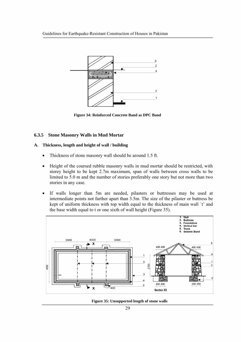
6.3.5 Stone Masonry Walls in Mud Mortar
A. Thickness, length and height of wall / building
• Thickness of stone masonry wall should be around 1.5 ft.
• Height of the coursed rubble masonry walls in mud mortar should be restricted, with storey height to be kept 2.7m maximum, span of walls between cross walls to be limited to 5.0 m and the number of stories preferably one story but not more than two stories in any case.
• If walls longer than 5m are needed, pilasters or buttresses may be used at intermediate points not farther apart than 3.5m. The size of the pilaster or buttress be kept of uniform thickness with top width equal to the thickness of main wall `t’ and the base width equal to t or one sixth of wall height (Figure 35).
Figure 34: Reinforced Concrete Band as DPC Band
Figure 35: Unsupported length of stone walls

Guidelines for Earthquake-Resistant Construction of Houses in Pakistan
30
B. Appropriate size and location of openings
For the stone masonry wall built in mud mortar, door and window openings may be located in the walls as follows:
• Total length of openings in a wall = 0.33 of wall length or one third (1/3) of the total wall length
• Distance of opening from inside corner: b5 > 2 ft. (600 mm)
• Pier width between consecutive openings > 2 ft. (600mm)
C. Good Quality of Stone masonry laying
• The thickness of walls should preferably be 1.5 ft (450mm). The stones of the inner and outer wythes should be interlocked with each other as far as possible.
• The masonry should preferably be brought to courses at not more than 2 ft. (600 mm) lift so as to achieve `coursed rubble masonry’.
• `Through’ stones of full length equal to wall thickness should be used in every 2 ft. (600 mm) lift at not more than 4 ft (1.2m) apart horizontally (Figure 37).
• In place of `through’ stones, `bonding elements’ of concrete bars of 50mm x 50mm section with an 8mm dia. rod placed centrally or solid concrete blocks of 150 x 150 x `wall thickness size’ may be used. (Figure 37). Alternatively, tree branches of 60 mm
Figure 36: Size and location of door and window openings

Guidelines for Earthquake-Resistant Construction of Houses in Pakistan
31
dia, or seasoned wooden battens of 50 mm x 50 mm size may be used as bonding element.
• Long stones of 2 ft (600 mm) length or solid concrete blocks of 150 x 150 x 600 mm size should be used at wall corners and T-junctions every 600 mm height to connect the perpendicular walls effectively (Figure 37 and 38). Alternatively, branches of 65 mm dia., or seasoned wooden batten of 60 mm x 60 mm size may be used.
• The mortar should be clay mud of good quality.
Figure 37: Layout of through stones in stone walls
Figure 38: Construction details of stone masonry wall

Guidelines for Earthquake-Resistant Construction of Houses in Pakistan
32
D. Horizontal seismic bands
To improve integrity, strength, and ductility of masonry house, its walls have to be reinforced horizontally and vertically. Vertical reinforcement helps to tie the walls to the foundation, and horizontal reinforcements help restrain out-of-plane bending and improve in-plane shear. Horizontal reinforcement helps to transmit the bending and inertia forces of transverse walls (out-of-plane) to the supporting shear walls (in-plane), as well as restraining the shear stresses between adjoining walls and minimizing vertical crack propagation. The horizontal and vertical reinforcement should be tied together and to the other structural elements (foundations, ring beam, roof). Placement of reinforcement must be carefully planned. Any ductile material such as bamboo, reeds, cane, vines, rope, timber, chicken wire, welded steel mesh, or steel bars can be used for reinforcement. Out of such strengthening measures horizontal seismic bands are discussed below.
A seismic band is a continuous beam that binds and reinforces orthogonal walls together. The seismic bands should be provided at the levels of plinth, lintel, floor and eaves. If possible, one seismic band should be provided at sill level also. The overall arrangement of seismic reinforcing of masonry buildings is shown in Figure 39. The seismic bands at various critical sections should be as follows:
1. Seismic bands at plinth, lintel, ceiling levels in buildings with flat roof will be provided in all internal and external walls continuously without break in all stories.
2. In case of sloping roofs, triangular gable walls must also be enclosed within eave level band and a band at the top of the gable wall.
3. The bands can be made of reinforced concrete sections as mentioned in the following section “stone masonry in cement mortar” or in case of stone masonry in mud mortar they could be of timber sections as described in the following paragraphs.
Figure 39: Overall arrangement of horizontal seismic bands

Guidelines for Earthquake-Resistant Construction of Houses in Pakistan
33
Plinth band: Plinth band is provided at the plinth level. If the plinth wall is constructed in stone or burnt-brick, it is advised to construct the plinth band in reinforced concrete. Plinth band is necessary if the foundation soil is soft. Such band may be avoided if the building is founded on hard soil. A separate damp proof course is not required if a plinth band is constructed.
Lintel band: Lintel band should be provided at the top level of doors and windows. It could be made of wood or reinforced concrete.
Details of horizontal seismic bands
A view of seismic band is shown in Figure 40. When constructing bands, special attention should be given to the connections, and L and T junctions (Figure 41). Diagonal struts help to stiffen the band at corners.
The horizontal could be in the following forms:
• Unfinished rough cut or sawn (5 cm x 12.5 cm in section) wood in single pieces provided with diagonal members for bracing at corners (Figure 41a).
• Unfinished circular sawn into halves (from 9 to 10 cm diameter log) or fully sawn wood (7.5 cm x 4 cm) in two pieces placed in parallel with halved joints at corners and junctions of walls. The longitudinal pieces will be braced by cross pieces (5 cm x 3 cm), or circular halves (6 cm diameter) with nailed joints.
• Alternatively, wooden ladder form can be used as seismic bands (Figure 41b).
In either case, the individual wooden pieces should be joined properly to make the band. The joints should have adequate overlapping with enough nails, or should be connected with iron-straps with sufficient nails/ screws to ensure the strength of the original wood at the joint. For enhancing durability, it is desirable to use seasoned wood. Chemical treatment against termite attack further enhances durability of the wood.
Figure 40: Isometric view of wooden seismic band in stone wall

Guidelines for Earthquake-Resistant Construction of Houses in Pakistan
34
E. Additional bands
Bands on pilasters and buttresses: Where pilasters or buttresses are used at corners and T-junctions (Figure 42), the seismic band should cover the buttresses as well.
Figure 42: Horizontal band on pillastered wall (Soruce: IAEE Guideline, 1986)
a) Rough cut lumber in single piece
b) Rough cut lumber in two parallel
Figure 41: Details of timber band

Guidelines for Earthquake-Resistant Construction of Houses in Pakistan
35
Sill band: In high seismic zone, a sill band is also advised. A sill band should be provided at window sill level going through all the walls except at the door locations. In case sill bands are found unaffordable, stitches should be provided at intermediate heights at spacing of 500 to 700 mm at L and T-junctions (Figure 43). It helps to prevent separation between orthogonal walls. These can be constructed of timber or even poly propylene bags or steel mesh.
Layout of wooden stitches for corner and Tee junctions ((adapted from IAEE, 1986)
Figure 43: Stitches at window sill level
F. Vertical reinforcement at corners, junctions and sides of openings
Vertical reinforcements should also be provided at each corners and T-junctions of the walls. For stone masonry in mud mortared houses, wooden planks of size 50 X 30 mm & 80 X 30 mm joined together by nails forming a L section is to be used and this vertical member is to be nailed to the wooden seismic bands at plinth, sill, lintel and eaves level (Figure 44). The vertical reinforcement is to be placed at all the corners of the rooms. Alternatively, steel reinforcing bars can also be provided as vertical reinforcement, which should be as described in the following section of “Stone Masonry in Cement Mortar”.

Guidelines for Earthquake-Resistant Construction of Houses in Pakistan
36
6.3.6 Stone Masonry Walls in Cement Mortar
A. Thickness, length and height of wall / building
• The height of the stone masonry walls in cement mortar should be restricted to two stories with flat roof or one story plus attic for pitched roof.
• The storey height to be kept 3.2m maximum, and span of walls between cross walls to be limited to 7.0m. If rooms longer than 7m are needed, buttresses may be used at intermediate points not farther apart than 5.0m. The size of the buttress be kept of uniform thickness with top width equal to the thickness of main wall and the base width equal to one sixth of wall height.
B. Appropriate size and location of openings
For stone masonry built in cement mortar and brought to courses, the door and window openings should be controlled as follows (Figure 45):
Ratio of total length of openings in a wall to length of the wall in a room should not exceed 0.5 in single storied, 0.42 in 2-storeyed and 0.33 in 3 storied buildings.
• Distance of opening from inside corner ≥ 450mm
Figure 44: Vertical reinforcement of stone wall with timber posts

Guidelines for Earthquake-Resistant Construction of Houses in Pakistan
37
• Pier width between consecutive openings ≥ 600mm
\
C. Good quality of stone masonry laying
• Mortar: The mortar in superstructure masonry should be cement-sand (1:6 in zones C & D and 1:4 zone AB). In the foundation masonry upto plinth, the mix 1:6 may be kept in all cases.
• Composite Mortar: In place of cement–sand 1:6 and 1:4 mortars, cement–lime–sand mortar may be used as 1:2:9 and 1:1:6 respectively.
• Wall Thickness: The wall thickness should not be larger than 380 mm (not more than 450 mm in any case) and the stones on the inner and outer wythes should be interlocked with each other as far as possible.
• Coursed: The masonry should preferably be brought to courses at not more than 600 mm lift.
• `Through’ Stone’: ‘Through’ stones of full length equal to wall thickness should be used in every 600 mm lift at not more than 1.2 m apart horizontally (Figure 46). In place of ‘through’ stones, ‘bonding elements’ of concrete bars of 50mm x 50mm section with an 8 mm dia rod placed centrally or solid concrete blocks of 150 x 150 x walls thickness, can also be used.
• Corner Stones: Long stones of 500-600mm length should be used at wall corners and T-junctions of walls. Alternatively use of 150 x 150 x (500 to 600) solid concrete blocks to connect the perpendicular walls effectively (Figure 46).
Figure 45: Appropriate size and layout of openings in stone house with cement mortar

Guidelines for Earthquake-Resistant Construction of Houses in Pakistan
38
D. Seismic bands at different locations
The overall arrangement of seismic bands will be same as that mentioned earlier in the stone masonry on mud mortar. However, in cement mortar building, the seismic bands should be reinforced concrete sections as shown in detail below:
For achieving good bond with masonry, the bands should be cast directly on the masonry and its top surface should be made rough. In the case of plinth and lintel band, stones may be cast in the concrete to project out of the concrete by 50 to 75mm.
Figure 46: Through stones and bond blocks for stone in cement walls
Figure 47: Section details of RCC band

Guidelines for Earthquake-Resistant Construction of Houses in Pakistan
39
Table 6: Size and no. of reinforcement bars in RC bands (for highly seismic areas)
Length of wall in room (m) Reinforcement bars (High Strength
Deformed Bars)
No. Diameter of bar
≤ 5 2 10 mm (3/8”)
6 2 12 mm (4/8”)
7 4 10 mm (3/8”)
E. Vertical reinforcement at corners, junctions and sides of openings
The vertical reinforcing of walls consists of a single high strength deformed (HSD) or `TOR' bar (See Table 7 for required diameters) located at each critical point as stated in 6.2.3.C.
Table 7: Size of vertical bars (for highly seismic areas)
No. of Stories Story Reinforcement bars (High Strength
Deformed Bars)
No. Diameter of bar
One 1 12 mm (4/8”)
Two Top 1 12 mm (4/8”)
Bottom 1 16 mm (5/8”)
Figure 48: RC Band Reinforcement detail at corners and junctions

Guidelines for Earthquake-Resistant Construction of Houses in Pakistan
40
The installation of a vertical bar in stone masonry can easily be effected by using a 75 mm diameter pipe casing around which the masonry is built to a height of 600 mm and 75 mm diameter. The pipe is kept loose by rotating it during masonry construction. Then the casing is raised up and the cavity filled around the bar with concrete (1:2:4) as shown in Figure 49. The concrete will not only provide a bond between the steel and the masonry, but it will also protect the bar from corrosion.
For installations of vertical bars in stone masonry, use of PVC casing pipe of 100mm external dia, 600-750 mm long is recommended around which masonry be built to height 450-600mm (Figure 49) and the pipe made loose by gently rotating. As the masonry hardens, the pipe is raised and the cavity filled with M20 concrete (nominal mix of 1:1.5:3) and fully compacted by rodding using 12mm dia and 600mm long bar.
Before casting the foundation, the vertical bars must be kept in correct in position horizontally and vertically. For this purpose tripods may be erected using bamboos or spare reinforcing bars (Figure 50).
Figure 49: Placing concrete around vertical bars in stone wall
Figure 50: Placement of vertical bars (keeping vertical)

Guidelines for Earthquake-Resistant Construction of Houses in Pakistan
41
Vertical Reinforcement at Jambs of Openings
The vertical bars are to be provided at the jambs of large openings in all buildings in higher seismic areas. However, in areas with seismicity, the openings can be boxed in R.C. with minimum 75 mm thickness and two reinforcing bars of 10 mm diameter (Figure 51).
6.3.7 Floor and Roof Construction
A floor / roof structure helps to tie up the walls together. The following general recommendations are given for enhancing seismic performance of the buildings.
• Roof/floor structure should be light.
• The floor joist, or roof beams or rafters should rest on a wall plate, preferably on the seismic bands at floor or eaves level. The joists and rafters should be well tied to the bands with nails or galvanized wire.
• Care should be taken to avoid placement of the floor joist, or roof beams or rafters just above door or window openings. Otherwise, the lintel band should be additionally reinforced as mentioned in Figure 71 in Chapter 8.
• The floor/ roof structure should be braced to improve integrity and stiffness.
• In high rainfall areas, large roof overhang should be provided to protect walls from wetting.
Figure 51: Strengthening masonry around window opening53

Guidelines for Earthquake-Resistant Construction of Houses in Pakistan
42
7 TIMBER HOUSE
Wooden construction has been regarded as one of the most suitable earthquake-resistant construction for residential houses since timber has higher strength per unit weight. However, its earthquake performance highly depends on the joints between different structural elements and the type and quality of infill between wooden elements. Hence, while constructing timber houses the joints should be made properly. Timber houses should be less than two storied.
7.1 DIFFERENT TYPES OF WOODEN WALL CONSTRUCTION
7.1.1 Stud Wall Construction
The stud-wall construction consists of timber studs and corner posts framed into sills, top plates and wall plates. Horizontal struts and diagonal braces are used to stiffen the frame against lateral loads due to earthquake and wind. The wall covering may consist of matting made from bamboo, reeds, and timber boarding or the like. Typical details of stud walls are shown in Figure 52. If the sheathing boards are properly nailed to the timber frame, the diagonal bracing may be omitted. The diagonal bracing may be framed into the verticals, or nailed to the surface. Other details are given below:
Figure 52: View of stud wall construction

Guidelines for Earthquake-Resistant Construction of Houses in Pakistan
43
7.1.2 Details of stud wall construction
Sill
The dimension of sill is kept 40 × 90, 90 × 90 (mm units) or larger. The sill is connected to the foundation by anchor bolts whose minimum diameter is 12 mm and length 35 cm. The anchor bolts are installed at both sides of joints of sills and at the maximum spacing is 2 m.
Studs
The minimum dimension of studs is 40 mm × 90 mm. If 90 mm × 90 mm studs are used the spacing may be doubled. Storey height should not be more than 2.70 m.
Top plates
The top of studs is connected to top plates whose dimension is not less than the dimension of the stud.
Bearing walls
Wall framing consisting of sills, studs and top plates should have diagonal braces, or sheathing boards so that the framings acts as bearing walls. In case no sheathing boards are attached, all studs should be connected to the adjacent studs by horizontal blockings at least every 1.5 m in height, Figure 53. The minimum dimension of braces is 20 mm × 60 mm. The brace is fastened at both ends and at middle portion by more than two nails whose minimum length is 50 mm to the framing members. The sheathing board is connected to the framing members by nails whose minimum length is 50 mm and maximum spacing is 150 mm at the fringe of the board and 300 mm at other parts.
7.1.3 Brick or Stone Nogged Timber Frame Construction
The brick nogged timber frame consists of intermediate verticals, columns, sills, wall plates, horizontal nogging members framed into each other. Diagonal braces may also be framed with the verticals or nailed or bolted on the faces. The space between framing members is filled with tight fitting brick or dressed stone masonry in stretcher bond.
Typical details of brick nogged timber frame construction are shown in Figure 53.

Guidelines for Earthquake-Resistant Construction of Houses in Pakistan
44
7.2 JOINTS IN WOOD FRAMES
The joints of structural members should be firmly connected by nails or bolts. The use of metal straps is strongly recommended at structurally important joints such as those of studs/columns with sill or wall plates and with horizontal nogging members.
7.3 FOUNDATION OF WOODEN HOUSE
The superstructure should be supported by concrete or masonry footings as shown in Figure 54. Openings for ventilation need be provided in continuous foundations. Some reinforcement as shown is also preferable in very soft soil areas and in areas where liquefaction is expected (Figure 55). On firm soil, isolated footings or boulders can also be used under the wood columns as shown in Figure 56.
Figure 53: Brick nogged timber frame construction

Guidelines for Earthquake-Resistant Construction of Houses in Pakistan
45
Figure 54: Foundation for timber construction

Guidelines for Earthquake-Resistant Construction of Houses in Pakistan
46
Figure 55: Foundation for timber construction in very weak soils
Figure 56: Wooden column footing

Guidelines for Earthquake-Resistant Construction of Houses in Pakistan
47
8 BRICK AND BLOCK MASONRY HOUSE
Relatively stronger houses can be achieved with bricks and blocks since these are regular rectangular masonry units which have relatively higher stability in it and quality control can also be achieved relatively easily.
Following are commonly available bricks and blocks in Pakistan:
1. Burnt Bricks of nominal size 230 x 110 x 70mm
2. Solid concrete blocks of nominal size 300 x 200 x 150mm.
3. Hollow concrete blocks of nominal size 300 x 200 x 150mm
8.1 MAIN FACTORS FOR ACHIEVING SEISMIC SAFETY IN BRICK / BLOCK MASONRY HOUSES
Following are the main factors for achieving increased earthquake safety in brick and block masonry houses:
1. Limited length and height of walls and appropriate thickness of walls
2. Appropriate size and location of openings
Figure 57: Different types of masonry units

Guidelines for Earthquake-Resistant Construction of Houses in Pakistan
48
3. Good quality of construction
4. Seismic bands at plinth, sill, lintel and eaves level and at gable
5. Well strengthened corners and T-junctions with stitches and dowels
6. Vertical reinforcement at corners, junctions and sides of openings
7. Bracing of floor and roof structure made of wooden beams and rafters
8.2 CONSTRUCTION OF BRICK MASONRY HOUSE IN MUD OR CEMENT MORTAR
Main features for making brick masonry buildings whether they are in mud mortar or are in cement mortar are same. However, relative seismic safety of these buildings differ, the cement mortared building being much safer one. Therefore, the permissible height of these two types of buildings as well as heights, thickness, length of individual walls differs. Following table gives the length and height of walls and the building:
Table 8: Thickness and height of brick masonry walls
Type of wall construction
Max. no. of stories
Story Min. Thickness of
wall (mm)
Height if individual wall (m)
Brick Masonry in Mud Mortar
2 Ground 350 3.2
First 350 3.0
Brick Masonry in Cement Mortar
3 Ground 350 3.2
First 230 3.0
Second 230 2.8
8.2.1 Foundation
Foundation for masonry building should be of strip footing as shown in Figure 58.

Guidelines for Earthquake-Resistant Construction of Houses in Pakistan
49
Figure 58: Foundation for one story building
Following size of foundation is recommended for different cases:
Table 9: Size of foundation footing
Type of Building For one story only
For Storied (or upto 3 storied for brick in
cement)
Width Height Width Height
Brick masonry in mud mortar
900 mm (3 ft)
800 mm (2.5 ft)
1000mm (3.3 ft)
1000mm (3.3 ft)
Brick Masonry in Cement mortar
900 mm (3 ft)
800 mm (2.5 ft)
900 mm (3 ft)
900 mm (3 ft)
All other construction details and treatment for brick masonry foundation are similar to those for foundation of stone masonry houses. Further, the foundation for brick masonry building may be of stone masonry footing as detailed in chapter 7.
Footing for Brick masonry in cement mortar
Footing for Brick masonry in mud mortar

Guidelines for Earthquake-Resistant Construction of Houses in Pakistan
50
8.2.2 Wall Construction
A. Length and Height of Walls
• When cement mortar is used with masonry units, the wall height from floor to ceiling should not exceed 15 times the wall thickness, and the length between cross-walls in a room should be less than 35 times the wall thickness but not larger than 8.0m.
• For houses, room height and length should preferably be restricted to 2.7m and 5.0m respectively in hilly areas and 3.2m and 6.0mm in plain areas.
• If above constraints are not met, either the wall thickness should be increased or appropriately designed intermediate columns, pilasters or buttresses should be provided to take care of the lateral seismic force.
B. Appropriate size and location of openings
Any opening in the wall should be small in size and centrally located. Following are the guidelines for size and position of openings (Figure 59).
• Openings are to be located away from inside corners by a clear distance equal to at least 1/4 of the height of the opening, but not less than 600 mm.
• The total length of openings in a wall are not to exceed 50 % of the length of the wall between consecutive cross-walls in single-story construction, 42 % in two-story construction, and 33 % in three-story buildings.
• The horizontal distance (pier width) between two openings is to be not less than one half of the height of the shorter opening, but not less than 600 mm.
• The vertical distance from one opening to another opening directly above it should not be less than 600 mm, nor less than one half the width of the smaller opening.
• When an opening does not comply with above, it should be boxed in reinforced jambs through the masonry as shown in Figure 60.
• If the vertical opening of the wall is more than 50 % of the wall height, vertical bars should be provided in the jambs.

Guidelines for Earthquake-Resistant Construction of Houses in Pakistan
51
Figure 59: Size and location of openings in brick wall with cement mortar
Figure 60: Strengthening of masonry around openings

Guidelines for Earthquake-Resistant Construction of Houses in Pakistan
52
If the wall is constructed with mud mortar the recommendation for openings is different than that with cement mortar. The openings should be as shown in Figure 61.
8.2.3 Good quality of construction
A. Good quality materials and brick laying
Good quality of materials and construction is the key to strength and durability of masonry as well as safer seismic performance. The following control measures will be significant for selection of good materials and good quality construction:
Bricks: The bricks should be of a standard rectangular shape, burnt red, hand-formed or machine-made. The higher the density and the strength, the better they will be. The standard brick size of 240 × 115 x 57 mm with 10 mm thick horizontal and vertical mortar joints is preferable. Tolerances of -10 mm on length, -5 mm on width and ± 3 mm on thickness are acceptable for the purpose of walls of the thickness specified in this Standard.
Figure 61: Openings in brick wall with mud mortar

Guidelines for Earthquake-Resistant Construction of Houses in Pakistan
53
Wall Thickness: A minimum thickness of one half-brick (115 mm) and a maximum thickness of one brick (240 mm) should be used for the walls constructed as non load-bearing walls in these buildings.
Mortar: Cement-sand mixes of 1:6 and 1:4 should be adopted for one-brick and half-brick thick walls, respectively. The addition of small quantities of freshly hydrated lime to the mortar in a lime-cement ratio of ¼:1 to ½:1 will increase its plasticity greatly without reducing its strength.
Plaster: All plasters should have a cement-sand mix not leaner than 1:6 on outside or inside faces. It should have a minimum 28 days cube crushing strength of 3 N/mm2. A minimum plaster thickness of 10 mm has to be adopted.
Once the good quality materials are selected, the quality of walls now depends on the quality of construction. The following control measures will be significant for good quality construction:
• All bricks to be laid should be soaked in water and all brick faces that are to be in contact with mortar should also be wetted; this can be achieved by spraying water;
• All courses of bricks should be laid level.
• Vertical joints should be broken between the consecutive courses by overlap of mud bricks. The joints should be fully filled with mortar.
• The joints between perpendicular walls should be made in such a way that through vertical joint is avoided. Layouts of alternate courses of bricks are shown in Figure 62 that avoid through vertical joints.
a) One block thick wall b) 1 brick and 1½ brick wall in Flemish Bond
Figure 62: Bonding between cross walls

Guidelines for Earthquake-Resistant Construction of Houses in Pakistan
54
• The cement mortar should be used within 60 minutes maximum after mixing of water in the mortar;
• All toothed joints, if any, should be fully filled with mortar while building the new masonry;
• The masonry should be cured by repeated sprinkling of water for at least for 7 days after the masonry is constructed using cement mortar.
B. Masonry Bond
In order to achieve the full strength of masonry, the usual bonds specified for masonry should be followed so that the vertical joints are broken properly from course to course.
Burnt bricks are normally used in English bond (Figure 63a) giving wall thickness of 100 - 114 mm for partition walls to be built in 1:4 cement-sand mortar; and 200 - 230 or 300 - 340 mm for load bearing walls.
For one storied lower cost houses, walls may be built using Rat-trap bond (Figure 63b) with Mortar of 1:4 mix. This will save about 25% of bricks and provide better thermal insulation also.
Figure 63: Bonds in brick masonry wall construction

Guidelines for Earthquake-Resistant Construction of Houses in Pakistan
55
C. Joints between orthogonal walls
For convenience of construction, builders prefer to make a toothed joint which is many times left hollow and weak. To obtain full bond it is necessary to make a sloping (stepped) joint by making the corners first to a height of 600 mm and then building the wall in between them (Figure 64). Otherwise, the toothed joint should be made in both the walls alternately in lifts of about 45 cm (Figure 65).
To further strengthen the connection between transverse walls, steel dowel bars as described in section 8.2.5 may be used at corners and T-junctions to enhance the box action of walls.
Figure 65: Alternate toothing joints in wall corners
Figure 64: Stepped joint construction

Guidelines for Earthquake-Resistant Construction of Houses in Pakistan
56
8.2.4 Horizontal seismic bands at different levels
A continuous band, also called 'ring beam' or ‘collar beam’ is a RC band or runner provided at different levels in all walls of the building for tying walls together to enhance box action. It improves horizontal bending resistance thereby preventing out-of-plane collapse of walls. It also helps to prevent shrinkage, temperature and settlement cracks. Bands at various levels are shown in Figure 66.
Plinth band: This is the band provided at plinth level which also acts as a damp proof course. This should be provided in cases where soil is soft or uneven in their properties.
Sill band: This band is provided just below the window openings. This becomes critical if the floor height is high.
Lintel band: This is the most important band and will incorporate in itself all door and window lintels. It must be provided in all stories of the building. Reinforcement required to span over openings should be in addition to band steel.
Floor and roof band: This band is required where timber or steel floor/roof structure has been used. It helps to integrate floor/roof structure with walls. Floor/roof structure should be tied with it for ensuring their stability during earthquake (Figure 67).
Gable band: Masonry gable walls must be enclosed in a band, the horizontal part will be continuous with the eave level band on longitudinal walls. The roof purlins should be tied up with sloping part of the band.
Figure 66: Bands at different levels

Guidelines for Earthquake-Resistant Construction of Houses in Pakistan
57
Section of bands or ring beam
The sectional view of horizontal seismic band is shown in Figure 68. The reinforcement of these bands may be kept as per Table 10. For longer spans, spans can be shortened by constructing intermediate columns or buttress. Thickness of band should be 75mm and 150 mm where two or four bars are used as longitudinal reinforcement respectively. The width of band should be kept equal to that of wall or otherwise designed. The steel bars are located close to the wall faces with 25 mm cover and full continuity is provided at junctions and corners.
Figure 68: Sectional views of horizontal RC seismic bands
Figure 66: Tying of floor beam or rafter with wall plate or floor band (Source: NSET, 2003)

Guidelines for Earthquake-Resistant Construction of Houses in Pakistan
58
Table 10: Requirement for steel in RC Band (for highly seismic areas)
Span of Walls (m) Reinforcement bars (High Strength
Deformed Bars)
No. Diameter of bar
≤ 5 m 2 10 mm (3/8”)
6 m 2 12 mm (4/8”)
Details
1. The width of the RC band ‘b’, Figure 69, is assumed to be same as the thickness of the wall. The minimum thickness of a load-bearing wall should be 230 mm. A cover of 25 mm from the face of wall should be maintained for all steel reinforcing.
2. The vertical thickness of the RC band may be kept to a minimum of 75 mm where two longitudinal bars are specified and to 150 mm where four longitudinal bars are specified.
3. The concrete mix is to be 1:2:4 by volume. Alternatively, it should have an M15 Grade cube crushing strength at 28 days.
4. The longitudinal bars should be held in position by steel stirrups 6 mm in diameter (or 5 mm diameter if Grade Fe550) spaced 150 mm apart.
Figure 69: RC Band Reinforcement details (sections and detail at corners and junctions)

Guidelines for Earthquake-Resistant Construction of Houses in Pakistan
59
In case of brick masonry in mud mortar the seismic bands could be of timber sections as mentioned in the construction of stone masonry buildings.
The lintel band can be avoided if the height of the wall is less than 2.5 m, however, in such cases; the individual lintels should be connected to the ceiling band at the levels of floor, eaves, or roof, as shown in Figure 70.
When individual lintels are provided above doors or windows, the bearing length of the lintel should not be less than 50cm in order to transfer the load to the wall without unduly stressing it.
Placement of floor/roof beam directly above the lintel should be avoided. If it is not possible, the lintel should be strengthened by providing an additional reinforcing lintel (Figure 71).
8.2.5 Well strengthened corners and T-junctions with stitches and dowels
As a supplement to the bands described above, steel dowel bars may be used at corners and T-junctions to integrate the box action of walls (Figure 72, 73 and 74). Dowels are placed in every fourth course or at about 50 cm intervals and taken into the walls to
Figure 71: Strengthening of Lintel Band (adapted from IAEE, 1986)
Figure 70: Connection of isolated lintel to eaves or roof level band

Guidelines for Earthquake-Resistant Construction of Houses in Pakistan
60
sufficient length so as to provide the full bond strength. Wooden dowels can also be used instead of steel. However, the dowels do not serve to reinforce the walls in horizontal bending except near the junctions.
Figure 73: Strengthening with dowel reinforcement and welded wire mesh
Figure72: Corner strengthening by dowel reinforcement

Guidelines for Earthquake-Resistant Construction of Houses in Pakistan
61
8.2.6 Vertical reinforcement at corners, junctions and sides of openings
Reinforcing bars have to be embedded in brick masonry at the corners of all the rooms and the side of the door openings for the increased seismic safety of houses. Window openings larger than 60 cm in width will also need such reinforcing bars. The diameter of the bar depends upon the number of stories of the house. The recommendations are same as given in the previous chapter on stone buildings.
Providing the vertical bars in the brickwork requires special techniques shown in Figure 75.
These vertical bars have to be started from the foundation concrete, will pass through all seismic bands where they will be tied to the band reinforcements using binding wire and embedded to the ceiling band/roof slab as the case may be using a 300 mm 90° bend. Sometimes the vertical bars will not be made in one full length. In that case the extension of the vertical reinforcement bars are required, an overlap of minimum of 50 times the bar diameter should be provided. The two overlapped reinforcement bars should be tied together by using the binding wires.
Figure 74: View of corner strengthening with dowel bars

Guidelines for Earthquake-Resistant Construction of Houses in Pakistan
62
8.3 CONSTRUCTION OF BLOCK MASONRY BUILDINGS
8.3.1 Types of concrete blocks
Two types of cement concrete blocks are commonly used:
1. Solid concrete blocks of nominal size 300 X 200 X 150 mm (actual size 290 X 190 X or 200 X 140 mm)
2. Hollow concrete blocks of nominal size 300 X 200 X 150 mm
Figure 75: Vertical reinforcement bars at corners and junctions
(a) – Hollow Concrete block (b) – Solid Concrete Block
Figure 76: Types of concrete blocks

Guidelines for Earthquake-Resistant Construction of Houses in Pakistan
63
A. Use of solid concrete block
1. Using the concrete blocks of 300 X 200 X 150 mm nominal size, non-load bearing walls of 150 mm thickness and bearing walls of 200 mm thickness could be built. The bearing surfaces of the blocks should be made rough by the casting procedure to develop good bond with the mortar. Alternatively, a frog could be created similar to that in the bricks (say 150 X 100 X 6 mm deep) so as to provide a shear key in the mortar joint.
2. Since unlike the bricks, breaking the blocks is not convenient, special L/2 and L/3 blocks (140 mm and 90 mm) should be cast and used to break the continuity of vertical joints (Figure 77).
3. Also, so as to fit the units without breaking, the size of doors, windows, built-in cupboard, open shelves, etc. and piers between them should be multiples of the modular dimensions of 100 mm.
Figure 77: Typical block layout for block wall construction

Guidelines for Earthquake-Resistant Construction of Houses in Pakistan
64
B. Use of hollow concrete block
Hollow blocks have larger breakage loss during transportation than the solid blocks. Hence a higher crushing strength on the solid portion of the hollow blocks is essential.
8.3.2 Construction of Block Masonry Walls
All the earthquake-resisting features for block masonry walls are same to those recommended for brick masonry buildings. However, there are some specific construction details for block masonry walls. These specific details are discussed here:
A. Horizontal Band in Hollow Concrete Block Masonry
U-shaped blocks should be used for construction of the horizontal bands at various levels of the storey as per the seismic requirements shown in Figure 78.
The amount of horizontal reinforcement may be taken as 25 % more than that given for brick wall construction and may be provided by using four bars and 6 mm diameter stirrups.
B. Vertical Reinforcement
Vertical Bars in Solid Concrete Block Walls
Since a cavity formation in solid block walls is not feasible, special concrete blocks with one hollow are cast and used at the bar-points. To avoid rising of the hollow blocks high for enclosing the bar in a hollow, slit is made in the wall of the hollow while casting the block.
Figure 78: Typical block layout for block wall construction

Guidelines for Earthquake-Resistant Construction of Houses in Pakistan
65
Vertical bars in Hollow Block Walls
Here cavities for locating the vertical bars are automatically available (Figure 80). Slit arrangement in the sides of the hollows for surrounding the bars will be required.
Figure 79: Corner solid block for placing vertical bar
Figure 80: Corner hollow block for placing vertical bar

Guidelines for Earthquake-Resistant Construction of Houses in Pakistan
66
8.4 FLOOR/ROOF CONSTRUCTION FOR MASONRY HOUSES
8.4.1 Flat floor / roof
A. Reinforced Concrete Slab floor / roof (rigid floor/roof)
RC slab construction is good from seismic point of view as it helps to improve integrity of building. RC slab should be constructed as described in the following chapter RCC framed construction.
B. Timber floor / roof (flexible)
Mud covering over a system of timber beams, joists is a common type of roof. However, such mud roofing is rarely used with brick or block wall construction. Whenever, it becomes necessary to construct mud floor/roof, the construction should be done as it is done for earthen construction. It will always be better to go for rigid type of floor / roof rather than the mud construction.
Use of Timber planks over a system of timber beams and joists is a common type of floor structure for masonry buildings. Timber joist have to be anchored into floor or roof bands by means of well distributed steel anchors as shown in Figure 81.
Different members of floor or roof structures should be well tied up with each other using nails and steel straps.
Wooden floors should be stiffened in their own plane. This can be achieved by one of the following means:-
• Two layers of planks: nailing planks perpendicular to first layer of planks as shown in Figure 82a.
Figure 81: Anchorage of timber joists in concrete band and timber wall plate

Guidelines for Earthquake-Resistant Construction of Houses in Pakistan
67
• RC topping: a cast-in-place RC topping, with a minimum thickness of 40 mm should be provided which is reinforced by 4.75 mm or 6 mm diameter bars placed at an interval of 200 mm in both directions. The reinforcement should be kept at mid height of topping as shown in Figure 82b. In such case, the ends of the reinforcement must be embedded into the RC floor or roof band.
Figure 82: Floor stiffening using two layers of planks and using RC toping
• Bracing: floors or flat roof can be stiffened by nailing diagonal wooden or steel straps or angles from underside of joist or rafter as shown in Figure 83.
8.4.2 Sloped roof with timber /steel structure and CGI sheet covering (flexible)
Pitched/sloped roofs may be trussed, with the top of the walls generally at one level - except for the masonry gables at the ends of the building. Alternatively, the longitudinal
a) Floor stiffening using two layers of planks
Figure 83: Floor stiffening using bracing
b) Floor stiffening using RC toping

Guidelines for Earthquake-Resistant Construction of Houses in Pakistan
68
and cross-walls may be raised to varying heights up to the roof slope and the rooms spanned by rafters and purlins. From a seismic design point of view, the trussed arrangement is preferable, particularly for school buildings.
A. Trussed Roof with cement wall construction
In trussed roofs, all trusses should be supported on the eave or roof-band. Where a trussed roof adjoins a masonry gable, the ends of the purlins should be carried on and secured to a plate securely bolted to the band at the top of gable-end masonry (Figure 84 and 85).
Figure 85: Details for fixing roof to wall
Figure 84: Roof fixing detail at gables for cement mortared wall

Guidelines for Earthquake-Resistant Construction of Houses in Pakistan
69
B. Slope roof for mud mortared wall
Various details of roofs for mud mortared walls are shown in the figures below:
Figure 86: Longitudinal wood as wall plate and ridge beam to support roof rafters
Figure 87: Roof support detail at lintel and wall

Guidelines for Earthquake-Resistant Construction of Houses in Pakistan
70
A-type truss are preferred to portal truss (Figure 89) to eliminate thrust on wall from roof.
Timber rafters or steel truss have to be anchored into roof bands by means of well distributed steel anchors as shown in Figure 90 or using wedges as shown in Figure 91.
Figure 88: Lintel and roof joint detail
Figure 89: Use of A-type truss

Guidelines for Earthquake-Resistant Construction of Houses in Pakistan
71
Roof truss and rafter should be braced by nailing or welding wooden members or steel straps/angles in horizontal as well as sloping planes of rafters as shown in Figure 92. Purlins should be well anchored into walls.
Figure 90: Anchorage of timber rafters into RC band using anchor bars
Figure 91: Anchorage of timber joists with wall using wedges
Figure 92: Roof bracing

Guidelines for Earthquake-Resistant Construction of Houses in Pakistan
72
9 REINFORCED CONCRETE BUILDINGS
With the spread of reinforced concrete construction to semi-urban and rural area in various countries, often buildings are constructed using reinforced concrete columns and beams, without proper engineering design, based on the experience of local masons and petty contractors. Use of isolated columns in parallel with load bearing walls for supporting long internal beams or those in verandahs and porches is becoming quite common. In most cases, such constructions suffer from deficiencies from the seismic view point since no consideration is given for the effect of seismic lateral loads and the connection details are usually such that no moment carrying capacity can be relied upon. Beams simply rest on top of columns and mostly held in position through friction.
The other serious deficiency is in concrete quality in respect of mixing, compacting and curing. The aim of this chapter is to provide working guidelines for such low-rise, (upto three stories) small buildings in RC frame constructions in which columns are supposed to resist vertical as well as horizontal seismic loads and the filler walls are assumed to be neither load bearing nor taking part in the lateral resistance of the building. Large halls for gymnasia, assembly halls, etc., having a floor area more than 60 m2 or beam spans more than 7 m must be designed by an engineer.
Hence this chapter discusses general requirements for construction of RC framed buildings. The reinforcement details prescribed should be observed in addition to that of reinforcement detail required for normal load.
9.1 FOUNDATION
If isolated footing is used as foundation, it is advised to connect them at foundation level or ground level or just below plinth level as shown in Figure 93. When a column terminates into a footing or a mat, special confining reinforcement should extend at least 300 mm into the footing or mat as shown in Figure 94. The spacing of confining reinforcement should not be more than 100 mm.
Figure 93: Tying of isolated footing
Figure 94: Special confining reinforcement

Guidelines for Earthquake-Resistant Construction of Houses in Pakistan
73
9.2 BEAM
9.2.1 Dimensions
• Beams should preferably have a width to depth ratio of more than 0.3.
• The width of the beam should not be less than 200 mm.
• The depth of the beam should preferably be not more than 1/4 of the clear span.
9.2.2 Longitudinal Reinforcement
• Top as well as bottom reinforcement should consist of at least two bars, of not less than 12 mm, throughout the member length.
• The tension steel in any face, at any section, should not be less than 0.3% (for concrete grade M15 or mix 1:2:4 and steel yield strength 415 MPa).
• The positive steel at a joint must be at least equal to half the negative steel at that section, subject to minimum of 0.2%.
• The maximum steel percentage on any face at any section should not exceed 2.5%.
• The steel provided at each of the top and bottom face of the member at any section along its length should at least equal to 1/4 of the maximum negative moment steel provided at the face of either joint.
• In an external joint, both the top and bottom bars of the beam should be provided with anchorage length, beyond the inner face of the column, equal to the development length in tension plus 10 times bar diameter minus allowance for 90 degree band (58xdiameter of bar for concrete grade M15 or mix 1:2:4) as shown in Figure 95.
• Splicing of bars by overlapping should be done using full development length (i.e. 56 x diameter of bar for concrete grade M15),
• Spliced length should be enclosed in stirrups spaced not more than 150 mm apart as shown in Figure 95.
• Not more than 50% of the bars should be spliced at any section. If the spacing between centers of splicing is more than 1.3 x lap length, staggered splicing should be considered.
• Splice position for bottom bars should be restricted to a region at least 2d (2x depth of beam) away from face of column but excluding the middle quarter length of effective span as shown in Figure 96.

Guidelines for Earthquake-Resistant Construction of Houses in Pakistan
74
• Top bars should be spliced in middle 1/3 of effective span as shown in Figure 96.
• All longitudinal bars of beam should pass through longitudinal bars of the column as shown in Figure 97.
9.2.3 Web Reinforcement
• Web reinforcement should consist of vertical stirrups. The closed stirrup should have a 1350hook as shown in Figure 98. The ends of the stirrup should be embedded in confined core as shown in Figure 98a. In compelling situation, it may also be made up of two pieces of reinforcement; a U stirrup with a 1350 hook and a 10 diameter extension at each end, embedded into confined core and a cross tie as shown in Figure 98b. A cross-tie is a bar having a 135º hook with a 10 diameter extension (but not <75 mm) at each ends. The hooks should engage peripheral longitudinal bars.
• The minimum diameter of stirrups should be 6mm. However, in beams with clear span exceeding 5m, the minimum bar diameter should be 8mm.
Figure 95: Anchorage beam bar
Figure 96: Lap splice in beam
Figure 97: Beam reinforcement details

Guidelines for Earthquake-Resistant Construction of Houses in Pakistan
75
• The spacing of stirrups over a length of 2d at either end of a beam should not exceed (a) d/4, and (b) 8 times diameter of smallest longitudinal bar. However, it need not be less than 100mm as shown in Figure 98. In rest of the length, stirrups should be provided at spacing not exceeding d/2.
9.3 COLUMN
9.3.1 Dimensions
The minimum dimension of the column should not be less than 200mm. However, in frames which have beams with centre to centre span exceeding 5m or columns of unsupported length exceeding 4m, the shortest dimension of the column should not be less than 300mm.
• The ratio of shortest cross sectional dimension to perpendicular dimension should preferably not be less than 0.4.
• Width of column should preferably be 75mm larger than the supported beam.
9.3.2 Longitudinal Reinforcement
Lap splices should be provided only in the central half of the unsupported member length as shown in Figure 56. It should be proportioned as a tension splice. (i.e. lap length should be 56φ for concrete mix 1:2:4 and high strength steel fy 415).
• Steel at any section should not be less than 0.8%.
Figure 98: Beam web reinforcement

Guidelines for Earthquake-Resistant Construction of Houses in Pakistan
76
• Bars less than 12 mm in diameter should not be used in column as longitudinal reinforcement.
• Closed hoops should be provided over the entire splice length at spacing not exceeding 150 mm or d/2, preferably 100 mm.
• Not more than 50% of bars should be spliced at any one section.
9.3.3 Web Reinforcement
• The stirrups should be closed type having a 135o hook with a 10-diameter extension (but not less than 75mm) at each end (Figure 100).
• The parallel legs of rectangular hoops should not be more than 300mm apart. If the length of any side of hoop exceeds 300mm, a cross-tie should be added (Figure 100).
• Alternatively, a pair of overlapping stirrups may be provided within the column (Figure 100)
9.4 BEAM COLUMN JOINT
9.4.1 Transverse Reinforcement
• In exterior columns stirrups as provided at the ends of column should also be provided through the beam-column joint (Figure 101)
Figure 99: Lap splice in column
Figure 100: Transverse reinforcement in column

Guidelines for Earthquake-Resistant Construction of Houses in Pakistan
77
• In interior beam-column joint which has beams framing into all vertical faces of it and where each beam width is at least 3/4 of the column width, stirrups may be provided at the spacing of 200 mm or d/2 whichever is less.
• Stirrups in the joint area may be provided as shown in Figures 102 and 103.
9.5 RC SLAB
RC slab construction is good from seismic point of view as it helps to improve integrity of building. The following types of floor and roof are recommended:
• Cast-in-place RC floors or roofs: Two–way floor or roof slab are preferred to one way.
Figure 102: Column and joint detailing
Figure 102: Hoop stirrups for joint
Figure 103: Stirrups for joint

Guidelines for Earthquake-Resistant Construction of Houses in Pakistan
78
• Floor or roof made of precast elements must be well connected to the tie-beam (seismic band) reinforcement. RC topping screed having minimum thickness of 40mm should be provided. A reinforcing mesh of 4.75mm or 6mm diameter bars at the 200 mm interval in both the orthogonal directions has to be placed at the mid-depth of topping as shown in Figure 104. These bars should be well integrated with tie beam.
• Span of cantilever structural elements, such as balconies and overhangs should be limited to 1.2 m as shown in Figure 105.
9.6 QUALITY OF CONCRETE
The concrete to be used in RCC construction should be good quality and also the method of construction should be good enough so that quality of building as a whole will be ensured. Following are the main factors to making good quality of concrete construction.
9.6.1 Concrete mix
In non-engineered reinforced concrete constructions, the proportions of concrete mix are usually kept 1:2:4 by volume of cement:sand:aggregate. The aggregate may be in the form of river shingle, or crushed stone, of maximum 20-mm size. It will be best to make the concrete mixture using whole bags of cement.
9.6.2 Mixing and placing of concrete
Where mixing is done manually without using a power driven mixer, it should be done on an impervious platform, say, using iron sheets or cemented floor.
For making a mix of 1:2:4,
Figure 104: Precast slab with RC topping
Figure 105: Cantilever slab

Guidelines for Earthquake-Resistant Construction of Houses in Pakistan
79
• Aggregates should first be measured and flattened on the platform,
• sand should be spread on the aggregate then, and finally
• cement poured at the top
The material should first be mixed thoroughly in dry state so as to obtain uniform color and then water added. The quantity of water should be enough to make a soft ball of the mixed concrete in hand. A little wetter mix is better for hand compaction and drier mix where vibrator is used for compaction. However, water should be as less as possible. Use concrete mortars or wall mortar within 45 minutes of mixing
9.6.3 Curing of concrete
Concrete work requires water-curing for a minimum of 14 days so as to gain its strength, otherwise the gain of strength is low and concrete becomes brittle.
Concrete slabs may be kept under water by ponding of water over it by making earthen barriers around the edges.
Columns should be kept covered with wet empty gunny bags. Keeping the side forms intact on the beam webs will prevent the evaporation of water from the concrete and help in curing.
Covering any concrete surface with polyethylene sheets after wetting the surface will help retain the moisture.
9.6.4 Construction joints
Where a joint is to be made, the surface of the concrete should be thoroughly cleaned and all laitance removed. The surface should be thoroughly wetted, and covered with a coat of neat cement slurry immediately before placing of new concrete. Construction joints in floors should be located near the middle of the spans of slabs, beams or girders, unless a beam intersects a girder at this point, in which case the joints in the girders should be offset a distance equal to twice the width of the beam. Provision of keys should be made for transfer of shear through the construction joint.

Guidelines for Earthquake-Resistant Construction of Houses in Pakistan
80
10 REPAIR AND STRENGTHENING OF EXISTING BUILDINGS
The retrofitting is the actions taken to upgrade the seismic resistance of an existing building so that it becomes safer under future earthquakes.
This can be in the form of providing seismic bands, eliminating sources of weakness or concentrations of large mass and openings in walls, adding shear walls or strong column points in walls, bracing roofs and floors to be able to act as horizontal diaphragms, adequately connecting roofs to walls and columns and also connecting between walls and foundations.
10.1 ASSESSMENT OF BUILDING DAMAGE
The assessment of building damage must be done before carrying out repairs or strengthening
Before commencing any repairs it is important to
• Determine the materials which have been used in the damaged building
• Carry out a detailed foundation check;
• Carry out a detailed structural assessment of the damaged building with particular attention to vulnerable elements of the structure.
This should be assessed by a qualified structural engineer. It should be noted that both nonstructural and structural repairs might be required to a building. The priority repairs should be to the structural components before embarking on any non- structural repairs (cracked slabs, falling plaster from walls and ceilings, rebuilding of parapets etc).
There is absolutely no point carrying out repairs to a building if the foundations have failed or the ground can no longer support the damaged building. Repairs to damaged foundations can be costly and difficult to instigate and hence a fine line may exist between demolishing the building or continuing with the repair.
Moreover, the site can become dangerous. In fact, earthquakes may cause failure of soft or loose ground whilst hillsides or sloping ground may become unstable. Whole towns and villages may be affected and although a building may appear safe for repair, near the foot of the slope or on it, further slope failures could be triggered by relatively small aftershocks or another future earthquake. Buildings in such terrain will require specialist advice of the stability of the whole area. No repairs to buildings should take place until this advice has been obtained

Guidelines for Earthquake-Resistant Construction of Houses in Pakistan
81
10.2 REPAIR AND STRENGTHENING
10.2.1 Foundations
One of the most frequent causes of deterioration of the walls of a house is their direct contact with the ground humid thus making them vulnerable in the event of an earthquake.
Example: ground sloping towards the wall, unstable and poor quality foundations and wall bases, prone to settling due to the effect of humidity and the inferior quality of the ground.
A. Alternative 1: Cleaning & Drainage
If after an earthquake the wall has cracks in certain sections and the adobe bricks are in a satisfactory state we must eliminate the earth which covers the wall base, and level out the ground a minimum of 10cm below the wall base.
Figure 106: Defects in foundation
Figure 107: Cleaning and drainage of foundation

Guidelines for Earthquake-Resistant Construction of Houses in Pakistan
82
B. Alternative 2: Demolition & Reconstruction
If after an earthquake the base of the wall has become loose, if there are cracks in the entire wall and sinking which make the wall unstable and dangerous we must then: Dismantle it after propping it up and build a new wall from the foundations.
10.2.2 Walls
After an earthquake, if a wall has become out of plumb by more than 2% per meter, then it will need to be dismantled or completely demolished since this deformation makes the wall lose its carrying capacity. To do this you will need to dismantle the wall after having checked the stability of the roof as described above.
Figure 108: Demolition and reconstruction of foundation
Figure 109: Deflection of existing walls

Guidelines for Earthquake-Resistant Construction of Houses in Pakistan
83
If the out of plumb is less than 1% and the walls do not show any signs of damage or diagonal cracks which cross it completely, the affected parts can be repaired.
A. Bricks walls
B. Gable wall
Cracks in gabled walls are frequent after earthquakes because generally they are free-standing without braces.
Figure 110: Damage in brick wall and improvement option
Figure 111: Crack in a gable wall

Guidelines for Earthquake-Resistant Construction of Houses in Pakistan
84
If during the assessment, it is observed that the gable is broken but stable and vertical, then we can repair and reinforce it with keys placed at right angles to the line of breakage. The details of such keys are as shown in Figure 112.
In the case of a bricks wall, to fit the keys it is advisable to drill the wall to make 5 cm diameter holes to fit the construction irons embedded in the cement mortar.
Figure 112: Strengthening of gable wall by providing keys
Figure 113: Making holes in a brick wall

Guidelines for Earthquake-Resistant Construction of Houses in Pakistan
85
Lightened Gable
If the earthquake has caused serious damage in the gabled wall and part of it has collapsed, then it is advisable to dismantle it and change it for a frame or a weatherboard which will be much lighter and more resistant in the event of an earthquake.
Using the "wattle and daub" technique consists of making a frame with cane, poles or made from a similar material, covered with clay mortar.
Figure 114 shows in detail the solution with cane or poles tied with galvanized wire and covered with earth mortar.
Figure 114: Making gable wall lighter using wattle and daub technique
C. Wall corner
Reinforcement with keys
Corner joints tend to be weak areas in the event of an earthquake, especially when they do not have correct bonding.
Figure 115: Cracks at corner

Guidelines for Earthquake-Resistant Construction of Houses in Pakistan
86
If the cracks are not serious and there is no loosening, then they can be repaired by fitting keys. It is advisable to fit them at 5 row intervals taking advantage of the mortar joints. Take great care when cutting the wall to fit the wooden parts which make up the key so as to cause as little damage as possible to the adobe. Afterwards cover any remaining spaces between the key and the wall with clay and straw mortar.
Figure 116: Corner strengthening with key
Dismantling and Reconstruction
When the walls have suffered greater damage, like collapsed sections, a more delicate operation is needed. First dismantle the wall in the form of a "staircase" on both sides, and then rebuild the wall with new bricks or stones. In order to avoid this happening again, fit supports at 4 row intervals (keys), these will be embedded in the wall. Another possibility is to rebuild with buttresses, in which case you will need to start from the foundations.
Figure 117: Dismantling damaged portion and reconstructing new wall

Guidelines for Earthquake-Resistant Construction of Houses in Pakistan
87
The figure below shows an alternative option to insert "keys". This solution uses wooden sticks or canes, and is equally efficient, in the event of an earthquake. Other materials and techniques can also be used: wood, bamboo or wire mesh with concrete.
10.2.3 Roof
After an earthquake, there may be cracks in the part which supports the load of the roof, mainly when the ring beam which distributes the load horizontally is missing. In such case, the cracked portion of wall can be replaced.
For this first of all, the roof structure above needs to be supported at the place where the replacement is being. Once the roof has been supported, the damaged adobes are eliminated and replaced. The topmost layer of the wall is removed and replaced with a ring beam or a wall plate (made from wood, cement, bamboo or a similar material). Afterwards the roof structure will return to its initial position.
There are two ways of fitting a ring beam:
1. Build a ring beam around the wall's entire perimeter if the wall is not gabled.
Figure 118: Corner strengthening with key
Figure 119: Cracks at the bottom of roof support

Guidelines for Earthquake-Resistant Construction of Houses in Pakistan
88
2. Or only on the parts which receive the roof, finishing at the ends with a key embedded in the gabled wall.
10.2.4 Floor bracing
In case of wooden or flexible floor, the rigidity of the floor should be increased. The rigidity of the floor can be increased by providing diagonal bracings.
Figure 120: Providing ring beams
Figure 121: Diagonal bracing of floor

Guidelines for Earthquake-Resistant Construction of Houses in Pakistan
89
REFERENCES 1. ADPC; Regional Workshop on Best Practices in Disaster Mitigation, Indonesia,
September 2002. 2. AKPBSP, BACIP; “Galvanized Wire-Mesh Wall Reinforcement Methodology”, “The
Development of the Wire-Mesh Knotting Equipment”, “BACIP Galvanized Wire-Mesh Wall Reinforcement”, “Development of the BACIP Wire-Mesh Knotting Equipment”, “BACIP, Insulation advice table”, Aga Khan Planning and Building Services, Pakistan (AKPBSP), Pakistan.
3. Arya, A. S. et al; Guidelines for Earthquake Resistant Non-Engineered Construction, International Association for Earthquake Engineering, 1986.
4. Arya, A. S.; Protection of Educational Buildings against Earthquakes, Education Building Report #13, UNESCO Principal Regional Office for Asia and the Pacific, Bangkok, Thailand, 1987.
5. Arya; Earthquake-Resistant Reconstruction and New Construction of Masonry Building in Jammu and Kashmir State, Prof. Anand S. Arya, National seismic Advisor, 2005
6. Coburn, A. and Spence, R.; Earthquake Protection, John Wiley and Sons. 7. CRA Terre; Anti-seismic Construction Handbook. 8. EERI; Annotated Slide Set: A visual presentation of EERI Slide Sets on CD, Earthquake
Engineering Research Institute (EERI). 9. IITK-BMTPC Earthquake Tip Series (www.nicee.org), Indian Institute of Technology,
Kanpur and Building Materials and Technology Promotion Council, New Delhi, India. 10. IS 13920-1993; Ductile Detailing of Reinforced Concrete Structures Subjected to
Seismic Forces – Code of Practice, Bureau of Indian Standards, New Delhi, India. 11. IS 1893-1984, Criteria for Earthquake Resistant Design of Buildings and Structures,
Bureau of Indian Standards, New Delhi, India. 12. IS 4326-1993; Earthquake Resistant Design and Construction of Buildings – Code of
Practice, Bureau of Indian Standards, New Delhi, India. 13. NBC 108-1994; Site Consideration, His Majesty’ Government of Nepal, Ministry of
Housing and Physical Planning, Department of Buildings, Nepal, 1995. 14. NBC 109-1994; Masonry: Unreinforced, His Majesty’ Government of Nepal, Ministry
of Housing and Physical Planning, Department of Buildings, Nepal, 1995. 15. NBC 201-1994; Mandatory Rules of Thumb: Reinforced Concrete Buildings with
Masonry Infill, His Majesty’ Government of Nepal, Ministry of Housing and Physical Planning, Department of Buildings, Nepal, 1995.
16. NBC 202-1994; Mandatory Rules of Thumb Reinforced Concrete Buildings without Masonry Infill, His Majesty’ Government of Nepal, Ministry of Housing and Physical Planning, Department of Buildings, Nepal, 1995.
17. NBC 202-1994; Mandatory Rules of Thumb: Load Bearing Masonry, His Majesty’ Government of Nepal, Ministry of Housing and Physical Planning, Department of Buildings, Nepal, 1995.

Guidelines for Earthquake-Resistant Construction of Houses in Pakistan
90
18. NBC 203-1994; Guidelines for Earthquake Resistant Building Construction: Low Strength Masonry, His Majesty’ Government of Nepal, Ministry of Housing and Physical Planning, Department of Buildings, Nepal, 1995.
19. NBC 204-1994; Guidelines for Earthquake Resistant Building Construction: Earthen Buildings (EB), His Majesty’ Government of Nepal, Ministry of Housing and Physical Planning, Department of Buildings, Nepal, 1995.
20. NSET; Earthquake Resistant Construction of Buildings Curriculum for Mason Training – Guidelines for Training Instructors, National Society for Earthquake Technology - Nepal; Asian Disaster Preparedness Centre, Kathmandu, February 2005.
21. NSET; Protection of Educational Buildings against Earthquakes: A Manual for Designers and Builders, National Society for Earthquake Technology – Nepal (NSET), Kathmandu, 2000.
22. The website of Earthquake Engineering Research Institute (EERI): www.eeri.org 23. The website of National Earthquake Information Center: www.neic.gov 24. The website of National Information Center for Earthquake Engineering (NICEE):
www.nicee.org 25. The website of United States Geological Survey (USGS): www.usgs.gov 26. UNCRD; Guidelines for Earthquake Resistant Design, Construction, and Retrofitting of
Buildings in Afghanistan, Ministry of Urban Development and Housing (MUDH), United Nations Centre for Regional Development (UNCRD), Afghanistan, June 2003.
27. UN-HABITAT; Guidelines for Earthquake Resistant Construction of Non-Engineered Rural and Suburban Houses in Afghanistan, Kabul, July, 2005
28. World of Natural Hazards, Munich Re Group, 2001.