Embed Size (px)
Citation preview

NORTHEAST
A Chapter of thePrecast/Prestressed Concrete Institute
Report Number PCINE-14-ABC
Guidelines For Accelerated Bridge Construction
Using Precast/Prestressed Concrete Elements Including Guideline Details
Date Issued August 27, 2014
PCI Northeast Bridge Technical Committee
Second Edition
Report No: PCINE-14-ABC
Copyright © 2014
By Precast/Prestressed Concrete Institute Northeast
Second Edition, first printing, 2014
All rights reserved. This guide or any part thereof may not be reproduced in any form without the written permission of the Precast/Prestressed Concrete Institute Northeast.
Printed in the U.S.A
Information contained in this work has been obtained from sources believed to be reliable. PCI Northeast or its memberships shall not be responsible for any errors, omissions, or damages arising out of this information. PCI Northeast has published this work with the understanding that PCI Northeast is supplying information only. PCI Northeast is not rendering engineering or other professional services through this guideline. If such services are required, please seek an appropriate professional.
ii NORTHEAST
A Chapter of thePrecast/Prestressed Concrete Institute
Report Number PCINE-14-ABC
Date Issued August 27, 2014
Guidelines For Accelerated Bridge Construction
FORWARD
This guideline has been developed for the purposes of promoting a greater degree of uniformity among owners, engi-neers, and industry of the Northeast, with respect to planning, designing, fabricating, and constructing highway bridges with the FHWA’s philosophy of accelerated bridge construction.
In response to needs determined by Northeast Transportation Agencies, and Prestressed Concrete Producers, the PCI Northeast Regional Bridge Technical Committee established a subcommittee comprised of a cross section of its members representing academia, transportation engineers, and producers to prepare this guide.
Contributors were Members of the PCI-NE Bridge Tech Committee that provided significant input for the preparation of the second edition of this manual:
Co-Editor: Rita Seraderian, PCI Northeast Executive Director (PCINE)
Co-Editor: Michael P. Culmo, CME Associates, Inc.
Jason Tremblay, New Hampshire DOT
Darren Conboy, Jacobs Engineering
Michael Twiss, New York State DOT
Scott Harrigan, The Fort Miller Co., Inc.
Vartan Sahakian, CH2M Hill
Joe Carrara, J. P. Carrara & Sons
Ernie Brod, J. P. Carrara & Sons
Ed Barwicki, Lin Associates
Eric Calderwood, Calderwood Engineering
Edmund Newton, Mass. Department of Transportation
iNORTHEAST
A Chapter of thePrecast/Prestressed Concrete Institute
Report Number PCINE-14-ABC
Date Issued August 27, 2014
Guidelines For Accelerated Bridge Construction
Forward i
Introduction iv
Section 1: Application Overview 5
1.1 When To Use Accelerated Construction 5
1.2 Rehabilitation Projects 5
1.3 Examples Of Prefabricated Elements 5
1.4 Architectural Treatments 5
Section 2: General Requirements 7
2.1 Partial Replacement Projects 7
2.2 Design 7
2.3 Geometric Configurations 72.3.1 Bridge Layout 72.3.2 Element Sizes And Shapes 7
2.4 Tolerances 7
2.5 Shipping And Handling 82.5.1 Lifting Devices 8
Section 3: Precast Elements 9
3.1 Foundation Elements 93.1.1 Piling 93.1.2 Footings 9
3.1.2.1 Construction On Bedrock 93.1.2.2 Construction On Soil 103.1.2.3 Construction On Piles 103.1.2.4 Leveling Devices 113.1.2.5 Grouting Under Footings 11
3.2 Substructure Elements 123.2.1 Retaining Wall Elements 12
3.2.1.1 Cantilever Walls 123.2.1.2 Soldier Pile Walls 133.2.1.3 Mechanically Stabilized Earth (Mse) 133.2.1.4 Concrete Modular Block Gravity Walls 133.2.1.5 Sheet Piling Wall 13
3.2.2 Columns 143.2.2.1 Column Shapes 14
3.2.3 Girder Support Elements 143.2.3.1 Pier Caps 143.2.3.2 Integral Abutment Pile Caps 15
3.2.3.3 Wall Caps 163.2.4 Approach Slabs 16
3.3 Superstructure Elements 173.3.1 Girders And Beams 17
3.3.1.1 Bulb Tee Girders (Nebt) & (Pcef) 173.3.1.2 Northeast Deck Bulb Tee 173.3.1.3 Northeast Extreme Tee (Next) Beam 183.3.1.4 Box Beam, Deck Beams, And Slabs 18
3.3.2 Full-Depth Deck Panels 193.3.3 Partial-Depth Deck Panels 20
3.4 Proprietary Bridge Systems 20
3.5 Bridge Railing And Parapets 20
Section 4: Joints 21
4.1 General 21
4.2 Layout Of Joints 21
4.3 Joint Width And Tolerance 214.3.1 Vertical Joints 224.3.2 Horizontal Joints 23
4.4 Structural Joints 244.4.1 Moment Connections 24
4.4.1.1 Embedded Mechanical Splicers 244.4.1.2 Cast-In-Place Closure Pours 254.4.1.3 Post Tensioning With Match-Cast Elements 25
4.4.2 Shear Connections 264.4.2.1 Vertical Grouted Keys In Wall Panels 264.4.2.2 Horizontal Joints In Wall Panels 264.4.2.3 Grouted Keys In Footings And Approach Slabs 264.4.2.4 Reinforced Dowels 27
4.4.3 Corrugated Metal Pipe Void Connections For Pile Connections 27
4.4.3.1 Corrugated Metal Pipe Void Connections For Wall Cap Connections 28
4.4.4 Deck Panel Connections 284.4.4.1 Panel To Panel Connections 284.4.4.2 Connections Of Full-Depth Deck Panels To Beams And Girders 29
4.4.5 Connections Between Adjacent Beams With Integral Full-Depth Decks 29
4.5 Non-Structural Joints 30
Contents
ii
Report Number PCINE-14-ABC
Date Issued August 27, 2014
NORTHEAST
A Chapter of thePrecast/Prestressed Concrete Institute
Guidelines For Accelerated Bridge Construction
Section 5: Grouting 31
5.1 Sub-Footings 31
5.2 Fill Under Spread Footings 31
5.3 Element To Element Grouting 325.3.1 Horizontal Surfaces 32
5.3.1.1 Recessed Key Connection 325.3.2 Vertical Joints 335.3.3 Mechanical Grouted Splices 34
5.4 Pile And Wall Caps 34
5.5 Post Tensioning Ducts 35
5.6 Blockouts For Anchoring Devices 36
Section 6: Seismic Considerations 37
6.1 General Criteria 37
6.2 Connection Of Superstructure To Substructure 376.2.1 Keeper Blocks 376.2.2 Pilasters/Cheekwalls 386.2.3 Abutment Backwall 386.2.4 Anchor Rods 386.2.5 Integral Connections 39
6.3 Column Connections 396.3.1 Column Base And Cap Connections 406.3.2 Splices Along Column Length 416.3.3 Confinement Reinforcement 41
6.4 Footings 416.4.1 Internal Reinforcement 416.4.2 Pile Connections 42
Section 7: Fabrication/Construction 43
7.1 Lifting Devices 437.1.1 Corrosion Protection 43
7.2 Equipment 437.2.1 Shipping And Handling 437.2.2 Slide-In Bridge Construction (SIBC) 43
7.3 Assembly Plan 44
7.4 Coordination 45
7.5 Tolerances 457.5.1 Fabrication Tolerance 46
7.5.1.1 Inserts, Voids, And Projecting Reinforcing 467.5.2 Erection Tolerances 46
7.5.2.1 Vertical Control In The Field 477.5.2.2 Horizontal Control In The Field 47
7.6 QA/QC 477.6.1 Repair Of Elements 487.6.2 Post Tensioning 487.6.3 Mechanical Grouted Splices 48
7.7 Backfill 487.7.1 Flowable Fill 497.7.2 Compacted Granular Fill 497.7.3 Foam Products 50
Section 8: References 51
Appendix A: Guide Details 53
Suggested Guide Details Precast Substructures 53
Suggested Guide Details Precast Approach Slabs 65
iii
Report Number PCINE-14-ABC
Date Issued August 27, 2014
NORTHEAST
A Chapter of thePrecast/Prestressed Concrete Institute
Guidelines For Accelerated Bridge Construction
Introduction
This guide is the second edition report developed by the PCI Northeast Bridge Technical Committee on the use of Precast/Prestressed Concrete Elements to accelerate the construction of bridge projects. The guide will assist designers in deter-mining which means and methods would be appropriate for considering accelerated construction techniques. This guide will offer solutions from deck replacement to total construction of a bridge.
Some of the considerations for accelerated construction are:• Improved work zone safety.• Minimizing traffic disruption during bridge construction.• Maintaining and/or improving construction quality.• Reducing life-cycle costs and environmental impacts.
Precast elements produced off site can be quickly assembled, and can reduce design time, cost, minimize forming, mini-mize lane closure time, and/or possibly the need for a temporary bridge.
The use of precast elements such as abutments, pier caps, pier columns, and precast footings can effectively minimize construction time, traffic disruption, and the impact of construction activities on the environment.
This guide is organized in the customary order of bridge construction; essentially from the ground up. The manual starts with general information that applies to the whole structure. Following this, the reader will find specific information regarding the different precast elements used in accelerated bridge construction. Joints and grouting considerations may then be reviewed as the structures design becomes more defined. The final step then becomes construction. The reader will find recommendations regarding fabrication and inspection of each element used in the structure. Therefore, the reader will find the guide is divided into the following seven sections:
1. Application Overview2. General Requirements3. Precast Elements4. Joints5. Grouting6. Seismic Considerations7. Fabrication/Construction
Details have been developed for the various elements described in this guideline. These can be found in Appendix A. Each detail has been numbered for easier cross-referencing. For example: See Detail 3 on Sheet SUB 4.
This guide is not intended as a stand-alone document and does not supersede the AASHTO specifications
iv NORTHEAST
A Chapter of thePrecast/Prestressed Concrete Institute
Report Number PCINE-14-ABC
Date Issued August 27, 2014
Guidelines For Accelerated Bridge Construction

Section 1: Application Overview
1.1 When To Use Accelerated Construction Accelerated construction techniques should be used where the benefits of accelerated construction have a positive effect on the construction costs and impacts of the project. In many cases accelerated construction tech-niques can reduce overall project costs. Bridge-specific costs on small, accelerated construction projects could be more than conventional construction for very rapid construction schedules (this is not necessarily the case with large scale projects). It is also anticipated that costs will come down as more accelerated projects are let. The savings in accelerated construction projects are found in other aspects of the project such as time, equipment use, and labor savings.
Decisions to use accelerated construction techniques should be made after considering the following issues:
• Temporary Roadways and Bridges• Reductions in Environmental Impacts• User Costs• Political Pressures• Long Detours
For additional guidance, refer to the Federal Highway Ad-ministration report titled “Decision-Making Framework for Prefabricated Bridge Elements and Systems (PBES), May 2006.” Several States have developed specific decision-making processes. Designers should check with the local DOT for guidance.
Accelerated construction should always be considered in cases where temporary bridges and roadways are antici-pated. This is especially true where a reasonable detour is available. It may be desirable to close a roadway com-pletely, build the bridge quickly, and live with a detour. In this case, the possible additional cost of the accelerated construction is far outweighed by the savings of not build-ing a temporary roadway. Recent accelerated construction projects have shown that commuters and businesses prefer a significant short-term impact over a long-term moderate impact.
For bridges over water courses, impacts to the environ-ment can be lessened by the elimination of a temporary bridge.
The cost of construction to highway users is significant. Savings to commuters are not typically reflected in con-struction budgets for highway projects; however there is a significant financial impact to the entire community due to travel delays. In many cases, the cost of accelerated construction techniques can be offset by reductions in user costs.
Often, the need for accelerated construction can be driven by political pressures. The impacts of construction on commuters and businesses in urban areas can be dev-astating. Accelerated construction can be used to limit the time frames for construction projects in these areas.
On some projects, the use of staging and temporary bridges is not feasible due to limited right of way and environmental issues. In these cases detours are the only option. Accelerated construction techniques should be considered if there are issues with traffic volumes on detours and access for emergency vehicles.
Though the intent of this manual is to provide informa-tion that applies to precast/prestressed elements used in bridge construction, using these elements in conjunction with non-precast elements is also encouraged. The de-signer may wish to use precast substructures with steel girders and precast deck panels, for example.
1.2 Rehabilitation ProjectsMany bridge rehabilitation projects may benefit from accelerated construction methods. This guide focuses on precast elements that could replace the entire bridge; however, portions of existing bridges can also be con-structed using these methods. The designer in these cases should balance the cost savings of not constructing new elements to the costs of rehabilitating existing ele-ments. Costs should include both financial resources and time.
1.3 Examples Of Prefabricated ElementsPrefabricated elements in accelerated bridge construc-tion are comprised of separately shipped pieces that are assembled in the field to form a larger structural element of the completed bridge. The figures 1.3-1, 1.3-2, 1.3-3 and 1.3-4 show typical substructure units constructed with precast concrete elements. Superstructure elements are included in this manual, but not in great detail. More information on superstructure elements can be found in other PCI Northeast documents (www.pcine.org).
1.4 Architectural TreatmentsAn accelerated construction environment does not preclude the idea of having an attractive bridge. In fact the very opposite is the reality. With some careful plan-ning, the resulting bridge can be built quickly and also be aesthetically pleasing.
In most cases, cost will not be a limiting factor. Precast el-ements allow for architectural enhancements at a relative-ly lower cost than cast-in-place concrete. All treatments
1-5NORTHEAST
A Chapter of thePrecast/Prestressed Concrete Institute
Report Number PCINE-14-ABC
Date Issued August 27, 2014
Guidelines For Accelerated Bridge Construction
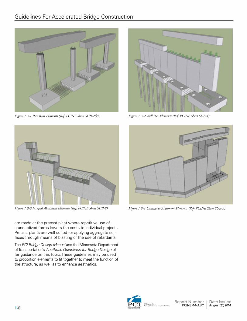
Figure 1.3-1 Pier Bent Elements (Ref: PCINE Sheet SUB-2&3)
Figure 1.3-3 Integral Abutment Elements (Ref: PCINE Sheet SUB-8) Figure 1.3-4 Cantilever Abutment Elements (Ref: PCINE Sheet SUB-9)
Figure 1.3-2 Wall Pier Elements (Ref: PCINE Sheet SUB-4)
are made at the precast plant where repetitive use of standardized forms lowers the costs to individual projects. Precast plants are well suited for applying aggregate sur-faces through means of blasting or the use of retardants.
The PCI Bridge Design Manual and the Minnesota Department of Transportation’s Aesthetic Guidelines for Bridge Design of-fer guidance on this topic. These guidelines may be used to proportion elements to fit together to meet the function of the structure, as well as to enhance aesthetics.
1-6 NORTHEAST
A Chapter of thePrecast/Prestressed Concrete Institute
Report Number PCINE-14-ABC
Date Issued August 27, 2014
Guidelines For Accelerated Bridge Construction
Section 2: General Requirements
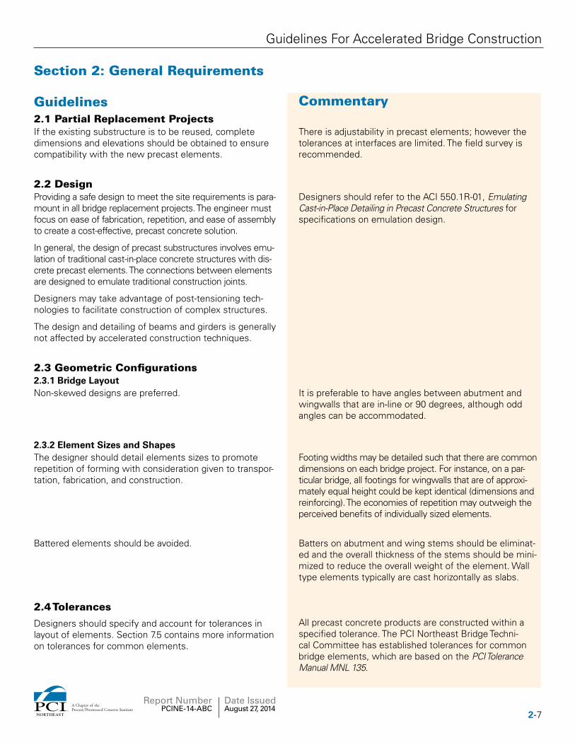
Guidelines Commentary2.1 Partial Replacement ProjectsIf the existing substructure is to be reused, complete dimensions and elevations should be obtained to ensure compatibility with the new precast elements.
There is adjustability in precast elements; however the tolerances at interfaces are limited. The field survey is recommended.
2.2 DesignProviding a safe design to meet the site requirements is para-mount in all bridge replacement projects. The engineer must focus on ease of fabrication, repetition, and ease of assembly to create a cost-effective, precast concrete solution.
In general, the design of precast substructures involves emu-lation of traditional cast-in-place concrete structures with dis-crete precast elements. The connections between elements are designed to emulate traditional construction joints.
Designers may take advantage of post-tensioning tech-nologies to facilitate construction of complex structures.
The design and detailing of beams and girders is generally not affected by accelerated construction techniques.
Designers should refer to the ACI 550.1R-01, Emulating Cast-in-Place Detailing in Precast Concrete Structures for specifications on emulation design.
2.3 Geometric Configurations2.3.1 Bridge LayoutNon-skewed designs are preferred. It is preferable to have angles between abutment and
wingwalls that are in-line or 90 degrees, although odd angles can be accommodated.
2.3.2 Element Sizes and ShapesThe designer should detail elements sizes to promote repetition of forming with consideration given to transpor-tation, fabrication, and construction.
Footing widths may be detailed such that there are common dimensions on each bridge project. For instance, on a par-ticular bridge, all footings for wingwalls that are of approxi-mately equal height could be kept identical (dimensions and reinforcing). The economies of repetition may outweigh the perceived benefits of individually sized elements.
Battered elements should be avoided. Batters on abutment and wing stems should be eliminat-ed and the overall thickness of the stems should be mini-mized to reduce the overall weight of the element. Wall type elements typically are cast horizontally as slabs.
2.4 Tolerances
Designers should specify and account for tolerances in layout of elements. Section 7.5 contains more information on tolerances for common elements.
All precast concrete products are constructed within a specified tolerance. The PCI Northeast Bridge Techni-cal Committee has established tolerances for common bridge elements, which are based on the PCI Tolerance Manual MNL 135.
2-7NORTHEAST
A Chapter of thePrecast/Prestressed Concrete Institute
Report Number PCINE-14-ABC
Date Issued August 27, 2014
Guidelines For Accelerated Bridge Construction
Erect and lay out elements based on common working lines. Base the layout of elements on dimensions measured from a common working line as opposed to nominal center-to-center spacing. The use of center-to-center spacing can result in loss of overall structure geometry due to cumulative erection tolerances (see the Typical Guideline Details for Precast Concrete Structures).
Nominal joint widths should be set based on the specified tolerances.
At a minimum, the joint width should account for the fabrication and erection tolerances of the elements. The PCI Northeast Bridge Technical Committee has estab-lished tolerances for common bridge joints based on this approach. See Sheets SUB 5, 6, and 10.
2.5 Shipping and Handling
The size of precast elements should be determined with consideration for shipping restrictions, equipment avail-ability, and site constraints.
The weight of precast substructure elements weighing on the order of 30 tons should be anticipated.
In special cases, very large pieces can be detailed; how-ever the shipping, handling, and installation costs should be considered.
It is possible to ship pieces in excess of 30 tons; howev-er the equipment required and limitation of local bridge capacities may restrict this. Off-loading of pieces can also be problematic. Larger pieces may be feasible if the pieces can be fabricated in close proximity to the bridge and shipped a short distance.
The designer should consider each state’s requirement for allowable shipping widths. The width of the element shall include all protrusions.
In general, elements should have a maximum width of 12 feet to avoid cost premiums typically associated with shipping of large elements over the road. Elements with widths in excess of 12 feet typically require special trucking permits, which can be supplied at a premium.
Precast elements shall be checked for stresses induced during handling and shipping. The design for handling is the responsibility of the fabricator. The PCI Design Hand-book, as well as lifting device manufacturer’s recommen-dations, should be specified as a reference for handling calculations. This requirement shall be included in the contract documents.
Reference: Latest edition of the PCI Design Handbook
2.5.1 Lifting Devices
The design and detailing of lifting devices is the respon-sibility of the fabricator. Lifting devices should be placed to avoid being visible once the precast element is placed. Lifting devices that are located in areas that will be vis-ible or exposed to the elements should be detailed with recessed pockets that can be patched after installation. The patching material should approximate the appearance of the surrounding concrete and provide corrosion protec-tion. See Section 7.1.
The designer should specify the level of corrosion pro-tection for lifting devices.
2-8 NORTHEAST
A Chapter of thePrecast/Prestressed Concrete Institute
Report Number PCINE-14-ABC
Date Issued August 27, 2014
Guidelines For Accelerated Bridge Construction
Section 3: Precast Elements
Guidelines Commentary
3.1 Foundation Elements
Foundation elements include piling, sheet piling, pile caps, and footings.
3.1.1 Piling
(Ref: PCINE Sheets SUB-7 & 8)
The designer may choose to use precast prestressed con-crete piles as an alternative to steel ‘H’-piles. Consult the project geotechnical report for specific limitations regard-ing the project site before selecting the pile type and size.
Practice has shown that a minimum of 14-inch prestressed pile sections has been successfully used in severe driv-ing conditions. For more information regarding precast/prestressed concrete piles, refer to the PCI Bridge Design Manual BM-20-04 chapter 20.
3.1.2 Footings
(Ref: PCINE Sheet SUB-7)
The transfer of footing loads to the underlying soils should be made via a filled gap below the footings (grout or flowable fill).
It is unreasonable to assume that proper interface can be achieved between compacted soil and a precast element. The unevenness of compacted soil combined with the toler-ances of precast will lead to point of localized support. An ef-fective means of providing this support is a grout-filled gap.
The most common standard finish on the underside of footings is a form finish. However, if greater coefficients of friction are required, several options are available to achieve the desired results. Costs of formwork and handling should be considered in determining the best approach.
Formliners and keyways are the most economical production practices. Sandblasting/ exposed aggregate finishes are also available; however, handling requirements may require rolling of panels. A rake finish with 1/4" amplitude is also an option but would require specialty forming and handling needs.
3.1.2.1 Construction on Bedrock
A more extensive soils boring program should precede con-struction of precast footings so that the degree of variation of top of rock elevations can be assessed prior to construction.
The uneven nature of construction of footings on bedrock may require preparation of the site prior to installation of precast footings. Over-blasting of rock by approximately 12" to provide room to prepare for a relatively level work area is recommended. This will facilitate the installation of grout or flowable fill under the footings. See Section 3.1.2.5.
Once the area is made roughly level, there are two recommended methods for preparing the area for installa-tion of precast footings. The first is to pour a low-strength concrete sub-footing that provides room for grouting. The second method is to provide small level concrete surfaces under the proposed leveling devices. See Section 3.1.2.4.
As with any construction on bedrock, large variations in rock elevations can affect the layout and design of precast substructure elements. It may be desirable to step footings where rock variations are significant. The contractor will also need this information to plan the work. Unknowns in rock elevations are always difficult to address. It is essential that most of this be addressed prior to construction on an accelerated project. The owner should balance the need for more borings with cost constraints.
The reason for over-blasting is to ensure that the removal of rock will be a one-time process, and the amount of post-blast clean-up removal will be kept to a minimum.
3-9NORTHEAST
A Chapter of thePrecast/Prestressed Concrete Institute
Report Number PCINE-14-ABC
Date Issued August 27, 2014
Guidelines For Accelerated Bridge Construction
The concrete sub-footing need not be high strength. The typical range of footing pressures are magnitudes less than the strength of the sub-footing concrete. The sub-footing concrete need not be formed. In most cases, the concrete can be cast against the footing excavation limits. Experience has shown that a low-strength concrete sub-footing does not slow construction and provides a very good work platform for installation of precast elements.
3.1.2.2 Construction on Soil
(Ref: PCINE Sheet SUB-7)
Prior to construction on soil, the area must be excavated and prepared as in normal cast-in-place construction.
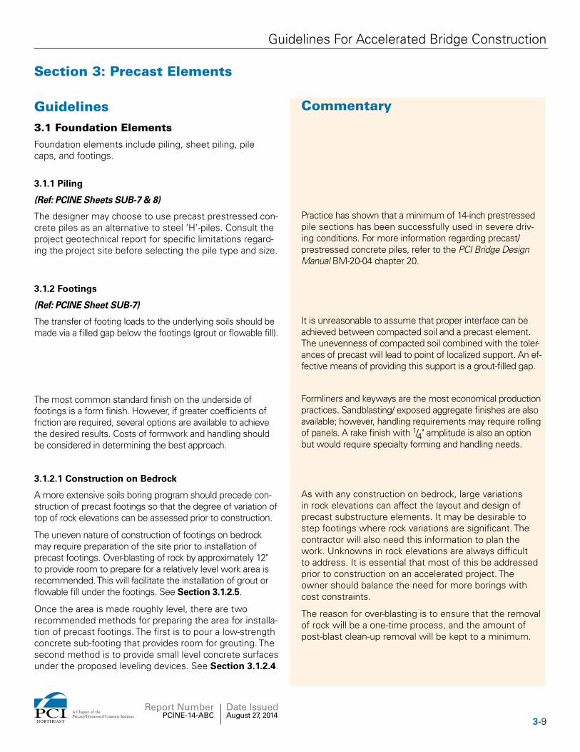
Once the area is prepared, there are two recommended methods for preparing the area for installation of precast footings. The first is to pour a low-strength concrete sub-footing to a level that is just below the proposed bottom of footing elevation as shown in Figure 3.1.2.2-1.
The second method is to provide small level areas un-der the proposed leveling devices. See Section 3.1.2.4. Temporary load distribution plates will be required under the leveling devices when a sub-footing is not used in order to spread the loads to the soil. This method is more cost effective, therefore it should be considered for most situations. Figure 3.1.2.2-1 Placing footing segment on a sub-footing.
3.1.2.3 Construction on Piles
(Ref: PCINE Sheets SUB-7 & 8)
Construction on piles will, in general, follow the guide-lines for construction on soil. A concrete sub-footing may be used, or the footing can be temporarily supported on load distribution plates on soil.
Provisions should be made in the footing design for concreting of the areas around the pile tops. Concrete is placed in the voids after setting of the pile cap footing or integral abutment cap.
Provide clearance around each pile to account for driving tolerances. See Notes 5 on Sheet SUB-1.
Designers should consider the use of cast-in-place con-crete footings for foundations with closely spaced piles and large foundations that lead to very heavy footing elements.
Typical state standards for pile installation tolerance are +6". This tolerance is normally too large for precast footings, since the voids in the footings need to be sized to accommodate the pile installation tolerance. In many cases, it is possible to install piles to a smaller toler-ance through the use of driving frames and templates. Tolerances of +3" have been attained without significant difficulty. Designers should consult with the project geo-technical engineer and the state agency prior to reducing the pile installation tolerance.
Closely spaced pile voids create difficulties with the spacing of reinforcing bars. In this case, the precast sub-structure stem can be set on temporary support struts, and the reinforcing bars can be projected into the footing pour, eliminating the need for connection hardware at the interface between the two elements. See Detail 6 on Sheet SUB-7.
3-10 NORTHEAST
A Chapter of thePrecast/Prestressed Concrete Institute
Report Number PCINE-14-ABC
Date Issued August 27, 2014
Guidelines For Accelerated Bridge Construction
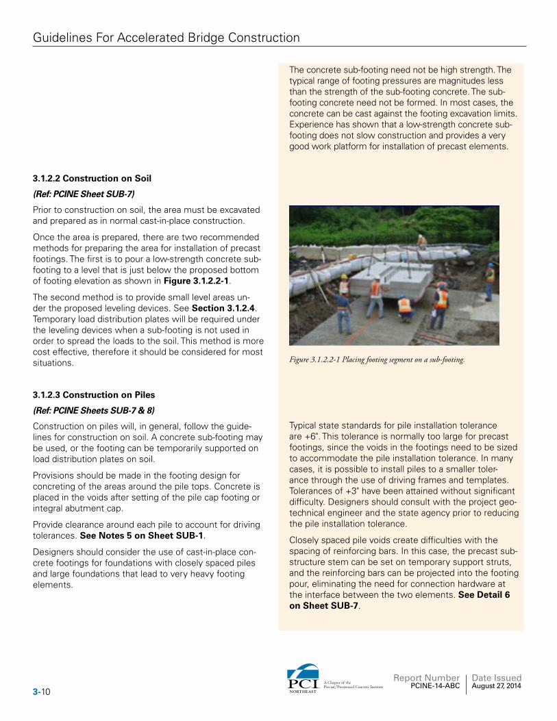
Construction of foundations in deep water can be facili-tated through the use of perched cast-in-place footings above the bottom of the body of water. Precast concrete elements can be used to form the footing and provide a dry work area for the footing installation.
Precast cofferdams are specialized structures that are specific to each project, which requires specialized design and detailing. Figure 3.1.2.3-1 shows a precast cofferdam that was used on the Providence River Bridge in Providence, R.I.
Figure 3.1.2.3-1 Precast Concrete Cofferdam.
3.1.2.4 Leveling Devices
(Ref: PCINE Sheet SUB-7)
Leveling devices are critical in maintaining proper vertical grade control on precast concrete substructures. Cast-in embedded leveling devices should be used to allow for adjustment of the footing grade and elevation during installation.
A minimum of four leveling devices should be specified for each spread footing element. Each device should be designed to support half the self-weight of the footing element.
The element should be leveled prior to release of the piece from the crane. A thorough greasing of the leveling device is recommended. See Detail 4 on Sheet SUB-7.
Once the installation of the element is complete, the leveling bolt may be left in place or backed out and the blockout filled with grout.
Experience has shown that these leveling devices pro-vide fast and easy grade adjustment at a minimal cost. The use of leveling shim packs is discouraged since there is no way to adjust the grades without removing the element.
During installation, there is a tendency for the piece to rock on the diagonal corner supports, therefore each device should be designed to support half the weight of the element.
The effort to adjust the leveling devices is greatly re-duced if the element is partially supported by the crane, or if it is greased.
3.1.2.5 Grouting Under Footings
(Ref: PCINE Sheet SUB-7)
The purpose of grouting under spread footings is to distribute the foundation pressures from the precast foot-ing to the underlying soil or rock. A gap that is grouted is required to achieve this. Exact grouting methods can be left up to the discretion of the general contractor. The plans and specifications should give certain guidelines on grouting procedures. See Section 5 for more information on grouting.
There are several methods that have been successfully used. The contractor should be allowed to use a method that best suits the experience of the workers and the available equipment.
3-11NORTHEAST
A Chapter of thePrecast/Prestressed Concrete Institute
Report Number PCINE-14-ABC
Date Issued August 27, 2014
Guidelines For Accelerated Bridge Construction
The strength of the grout is secondary to its ability to properly fill the gap under the footing. Flowable fill is another option for a fill material that can be used.
In most cases, the foundation bearing pressures are significantly less than the capacity of most grouts. A more cost-effective material for this situation is flowable fill (also referred to as controlled density fill). Flowable fill typically has strength that is sufficient to support most spread footings. It can be placed in small voids and has sufficient fluidity to spread under the footing between the fill ports.
The fill material should be placed in the void through ports cast in the footing. Attempting to flow the grout from one side to another is not recommended unless the footing is relatively narrow.
Placement may be accomplished by pumping or gravity feed through grout ports. The ports should be arranged so that the grouting operation progresses in a single general direction to avoid air pockets.
3.2 Substructure Elements
Substructure elements include wall segments, columns used in piers, approach slabs, and pier caps.
3.2.1 Retaining Wall Elements
There are several wall options available to designers for accelerated construction projects. Many States maintain approved proprietary precast concrete retaining wall systems. Another option is to use a precast concrete cantilever wall. The following options should be evaluated for each wall:
Designers should refer to each state’s specifications for a listing of the approved proprietary walls and for the proper methods for specifying them.
3.2.1.1 Cantilever Walls
(Ref: PCINE Sheet SUB-10)
Cantilever walls are concrete walls consisting of a con-crete footing combined with a concrete vertical wall ele-ment. The footing engages the backfill material to resist the overturning and sliding forces acting on the wall.
Cantilever retaining walls can be detailed using the techniques outlined in this guideline. The wall stems and footings can be made with precast concrete elements.
Cantilever wall footings can be placed on sub-soil (spread footing) or on piles.
See Detail 8 on Sheet SUB-10.
Often this type of wall will use the least amount of width (normal to wall face) when compared to other retaining wall systems.
3-12 NORTHEAST
A Chapter of thePrecast/Prestressed Concrete Institute
Report Number PCINE-14-ABC
Date Issued August 27, 2014
Guidelines For Accelerated Bridge Construction
3.2.1.2 Soldier Pile Walls
(Ref: PCINE Sheet SUB-10)
Soldier pile walls consist of vertical pile elements that are installed at regular intervals combined with prefabricated panels that are placed between the piles to retain the earth.
Soldier pile retaining walls can be detailed using the tech-niques outlined in this guideline for integral abutments. The wall stems can be made with precast concrete elements.
For tall walls, or walls that are built over shallow bedrock, the resistance of the vertical piles can be increased through the use of soil or rock anchors placed at regular intervals.
See Detail 9 on Sheet SUB-10.
Many contractors use temporary soldier pile walls for excavation support. In these cases, timber panels are typically used as lagging between the piles. Permanent soldier pile walls are made with precast concrete panels with the pile embedded in the precast element for long-term durability.
3.2.1.3 Mechanically Stabilized Earth (MSE)
Mechanically stabilized earth walls are designed based on the technique of engaging the soil mass behind the wall face through the use of layers of reinforcing strips or grids. Once engaged, the soil mass provides a gravity unit that can resist overturning and sliding. The reinforc-ing strips can be made of corrosion protected steel, or polymers.
A precast concrete facing element is typically used to retain the soil near the face of the wall.
Using MSE walls is an ideal solution for accelerated con-struction. The wall facing, reinforcing strips, and backfill can be constructed concurrently, which makes this wall type ideal for fill situations.
3.2.1.4 Concrete Modular Block Gravity Walls
Retaining walls can be constructed with precast concrete modular elements that are filled with compacted soil or crushed stone.
A precast concrete modular block gravity wall is another ideal solution for accelerated construction. The blocks in-terlock using keys cast into them. The dead weight of the blocking system along with the interlocking keys elimi-nates the need for mechanical connections between precast units.
Modular block walls are typically proprietary items. Refer to state-approved wall suppliers.
3.2.1.5 Sheet Piling Wall
Sheet piling retaining walls can be constructed using precast prestressed interlocking sheet elements that are placed in line to form a cantilever wall. The top of the wall is typically capped with cast-in-place concrete.
The sheets support the soil through cantilever action. For tall walls, soil anchors can be used to help resist the lateral soil forces.
These walls have been used in favorable soil conditions (sandy soils). Hydro-jetting is often used to facilitate sheet installation.
Details for sheet piling walls can be found at the Florida DOT website.
3-13NORTHEAST
A Chapter of thePrecast/Prestressed Concrete Institute
Report Number PCINE-14-ABC
Date Issued August 27, 2014
Guidelines For Accelerated Bridge Construction
3.2.2 Columns
3.2.2.1 Column Shapes
(Ref: PCINE Sheet SUB-5)
Rectangular, hexagonal, or octagonal columns are a preferred choice to facilitate fabrication.
Round columns are possible, but more difficult to fabri-cate. These will likely have to be poured vertically which may prove to be difficult in a precast plant. This will likely result in higher element prices.
Columns with at least one flat face can be poured on their sides. Several can be poured at the same time – side by side. This can enhance the efficiency and there-fore reduce the cost of the element.
Hexagonal and octagonal columns can be detailed with spiral reinforcement that mimics the behavior of round columns.
3.2.3 Girder Support Elements
Precast elements can be used to distribute girder loads to foundations. The most common elements are as follows:
3.2.3.1 Pier Caps
(Ref: PCINE Sheets SUB 2, 3 & 4)
A pier cap is a beam that spans the columns it is being set upon. The cap is connected to the columns by grouted mechanical splices.
PCI Northeast details are based on the use of grouted mechanical splices. Pier caps can also be connected using post-tensioning systems.
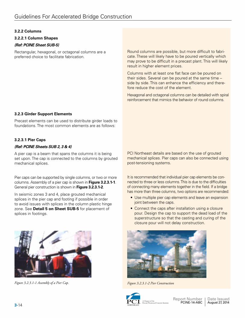
Pier caps can be supported by single columns, or two or more columns. Assembly of a pier cap is shown in Figure 3.2.3.1-1. General pier construction is shown in Figure 3.2.3.1-2.
In seismic zones 3 and 4, place grouted mechanical splices in the pier cap and footing if possible in order to avoid issues with splices in the column plastic hinge zone. See Detail 5 on Sheet SUB-5 for placement of splices in footings.
It is recommended that individual pier cap elements be con-nected to three or less columns. This is due to the difficulties of connecting many elements together in the field. If a bridge has more than three columns, two options are recommended:
• Use multiple pier cap elements and leave an expansion joint between the caps.
• Connect the caps after installation using a closure pour. Design the cap to support the dead load of the superstructure so that the casting and curing of the closure pour will not delay construction.
Figure 3.2.3.1-1 Assembly of a Pier Cap. Figure 3.2.3.1-2 Pier Construction
3-14 NORTHEAST
A Chapter of thePrecast/Prestressed Concrete Institute
Report Number PCINE-14-ABC
Date Issued August 27, 2014
Guidelines For Accelerated Bridge Construction
3.2.3.2 Integral Abutment Pile Caps
(Ref: PCINE Sheet SUB-8)
Pile caps are typically used in integral abutment bridges. There are two types of integral abutments: fully integral and semi-integral. Fully integral abutments provide a full moment connection to the superstructure while semi-integral abutments have a pinned connection to the superstructure allowing the superstructure to rotate. See individual state agency guidelines and details for the each state’s preferred approach.
The key feature of this method is the corrugations in the pipe. These corrugations are necessary to transfer the forces between the concrete cast within the pipe and the surrounding precast concrete. It is important to specify a pipe that has continuous and uniform corrugations along the entire length of the pipe so that the full concrete section can be engaged for shear transfer.
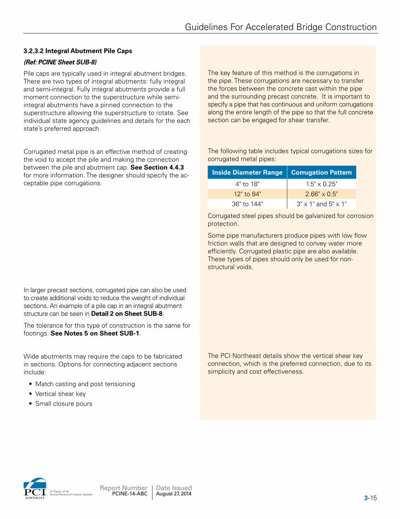
Corrugated metal pipe is an effective method of creating the void to accept the pile and making the connection between the pile and abutment cap. See Section 4.4.3 for more information. The designer should specify the ac-ceptable pipe corrugations.
The following table includes typical corrugations sizes for corrugated metal pipes:
Inside Diameter Range Corrugation Pattern
4" to 18" 1.5" x 0.25"
12" to 84" 2.66" x 0.5"
36" to 144" 3" x 1" and 5" x 1"
Corrugated steel pipes should be galvanized for corrosion protection.
Some pipe manufacturers produce pipes with low flow friction walls that are designed to convey water more efficiently. Corrugated plastic pipe are also available. These types of pipes should only be used for non- structural voids.
In larger precast sections, corrugated pipe can also be used to create additional voids to reduce the weight of individual sections. An example of a pile cap in an integral abutment structure can be seen in Detail 2 on Sheet SUB-8.
The tolerance for this type of construction is the same for footings. See Notes 5 on Sheet SUB-1.
Wide abutments may require the caps to be fabricated in sections. Options for connecting adjacent sections include:
• Match casting and post tensioning• Vertical shear key• Small closure pours
The PCI Northeast details show the vertical shear key connection, which is the preferred connection, due to its simplicity and cost effectiveness.
3-15NORTHEAST
A Chapter of thePrecast/Prestressed Concrete Institute
Report Number PCINE-14-ABC
Date Issued August 27, 2014
Guidelines For Accelerated Bridge Construction
3.2.3.3 Wall Caps
(Ref: PCINE Sheets SUB 4 & 9)
Precast caps should be used on top of wall stem ele-ments to simplify the detailing of the substructure.
Beam seats typically require complicated details in order to provide variable beam seat elevations. The use of a precast cap allows for the complex detailing to be limited to fewer elements as opposed to each wall stem ele-ment. Precast abutment caps can also be detailed to include integral backwalls and cheekwalls.
The connection of the wall stems to the caps can be done through the use of reinforcing bar dowels placed within a corrugated metal pipe void in each element. (See Detail 4 on Sheet SUB-6.)
Precast wall caps can be used on projects where the sub-structures are to be rehabilitated. The existing substructures can be removed to an elevation that is approximately 2 feet below the new beam seat. The new wall cap can then be connected through the use of grouted dowels.
3.2.4 Approach Slabs
(Ref: PCINE Sheets APP-1 through 5)
Approach slabs are designed to span between the bridge abutment and the approach fill. Details for approach slabs vary by agency. Precast approach slabs can be used and detailed to meet the specific requirements of each agency.
The purpose of approach slabs is to span over potential settlement of the soil directly behind the abutment. Most states set approach slabs at the surface of the roadway. Some states set the approach slabs below grade and fill on top of the slab with subbase and pave-ment. Buried approach slabs perform the same purpose as surface approach slabs, except that the slabs are bet-ter protected from deicing salts.
Various details have been developed by the PCI Northeast Bridge Technical Committee that depict various options that correspond to different state standards. The committee has also included details of precast barriers that are integral with the approach slab. Designers should select details that are consistent with the agency standards.
There are proprietary approach slab systems in the mar-ket that can be used.
Approach slabs need not be supported on the substrate over their entire length. The slab only needs to be sup-ported at the ends. The slab is normally supported by the abutment on one end and soil, or a sleeper slab at the far end. The area between the two supports need not be in contact with the ground.
The use of grouts under approach slabs is not required since the soil will most likely settle over time, leading to gaps. This is accounted for in the design of the approach slab. Flowable fill, which is less expensive than grout, can be used to seat the approach slab on the substrate at the ends, or if desired, along the entire approach slab.
3-16 NORTHEAST
A Chapter of thePrecast/Prestressed Concrete Institute
Report Number PCINE-14-ABC
Date Issued August 27, 2014
Guidelines For Accelerated Bridge Construction
3.3 Superstructure Elements
3.3.1 Girders and Beams
Girders or beams shall be designed and detailed according to conventional methodology. Refer to the PCI Bridge Design Manual, the AASHTO LRFD Bridge Design Specifications, and specific state agency standards.
3.3.1.1 Bulb Tee Girders (NEBT) & (PCEF)
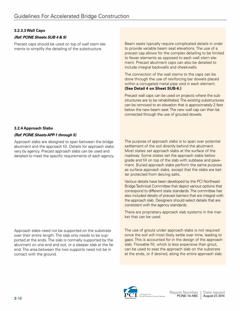
Figure 3.3.1.1-1 NEBT.
Bulb tee girders are precast/prestressed girders that are designed to be more efficient than traditional AASHTO I girders. It is a stringer bridge system with a concrete deck that is either cast-in-place or precast. It was devel-oped for bridge spans 80 feet and longer. The design of the girders could be simple span up to 160 feet or be spliced
to achieve spans up to 200 feet. Standard girders are available in depths of 39.4 inches (1000 mm) to 86.6 inches (2200 mm). Specialty girders can be fabricated beyond this limit. A typical NEBT Girder is shown in Figure 3.3.1.1-1.
The PCI Northeast Bridge Technical Committee devel-oped the Northeast Bulb Tee (NEBT) in 1995. This girder was developed as a metric section, which is the reason for the uneven girder depths. The girders are occasionally referred to with their metric depth designations.
Deeper girders can be considered on a case-by-case basis. Designers should contact fabricators to determine feasibility and shipping implications.
The PCEF (Prestressed Concrete Committee for Eco-nomic Fabrication) girder was developed by the mid-Atlantic states and is similar to the NEBT. The two are commonly interchanged with owner approval in the Northeast.
3.3.1.2 Northeast Deck Bulb Tee
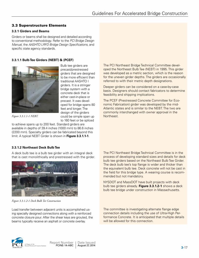
A deck bulb tee is a bulb tee girder with an integral deck that is cast monolithically and prestressed with the girder.
Figure 3.3.1.2-1 Deck Bulb Tee Construction
The PCI Northeast Bridge Technical Committee is in the process of developing standard sizes and details for deck bulb tee girders based on the Northeast Bulb Tee Girder. The deck bulb tee’s top flange is wider and thicker than the equivalent bulb tee. Deck concrete will not be cast in the field for this bridge type. A wearing course is recom-mended but not mandatory.
NYSDOT and MassDOT have built projects with deck bulb tee girders already. Figure 3.3.1.2-1 shows a deck bulb tee bridge under construction in Massachusetts.
Load transfer between adjacent units is accomplished us-ing specially designed connections along with a reinforced concrete closure pour. After the shear keys are grouted, the beams typically receive an asphalt or concrete overlay.
The committee is investigating alternate flange edge connection details including the use of Ultra-High Per-formance Concrete. It is anticipated that multiple details will be allowed for this connection.
3-17NORTHEAST
A Chapter of thePrecast/Prestressed Concrete Institute
Report Number PCINE-14-ABC
Date Issued August 27, 2014
Guidelines For Accelerated Bridge Construction
For more information on the design and construction of deck bulb tee beams refer to NCHRP 12-69 Final Project Report, “Guidelines For Design And Construction Of Decked Precast, Prestressed Concrete Girder Bridges.”
3.3.1.3 Northeast Extreme Tee (NEXT) Beam
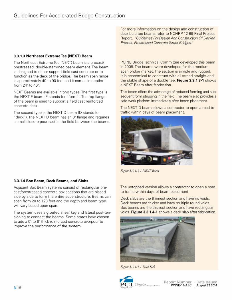
The Northeast Extreme Tee (NEXT) beam is a precast/prestressed, double-stemmed beam element. The beam is designed to either support field cast concrete or to function as the deck of the bridge. The beam span range is approximately 40 to 90 feet and it comes in depths from 24" to 40".
NEXT Beams are available in two types. The first type is the NEXT F beam (F stands for “form”). The top flange of the beam is used to support a field cast reinforced concrete deck.
The second type is the NEXT D beam (D stands for “deck”). The NEXT D beam has an 8" flange and requires a small closure pour cast in the field between the beams.
PCINE Bridge Technical Committee developed this beam in 2008. The beams were developed for the medium-span bridge market. The section is simple and rugged. It is economical to construct with all strand straight and the stable shape of a double tee. Figure 3.3.1.3-1 shows a NEXT Beam after fabrication.
This beam offers the advantage of reduced forming and sub-sequent form stripping in the field. The beam also provides a safe work platform immediately after beam placement.
The NEXT D beam allows a contractor to open a road to traffic within days of beam placement.
Figure 3.3.1.3-1 NEXT Beam
3.3.1.4 Box Beam, Deck Beams, and Slabs
Adjacent Box Beam systems consist of rectangular pre-cast/prestressed concrete box sections that are placed side by side to form the entire superstructure. Beams can span from 20 to 120 feet and the depth and beam type will vary based upon span.
The system uses a grouted shear key and lateral post-ten-sioning to connect the beams. Some states have chosen to add a 5" to 6" thick reinforced concrete overpour to improve the performance of the system.
The untopped version allows a contractor to open a road to traffic within days of beam placement.
Deck slabs are the thinnest section and have no voids. Deck beams are thicker and have multiple round voids. Box beams are the thickest section and have rectangular voids. Figure 3.3.1.4-1 shows a deck slab after fabrication.
Figure 3.3.1.4-1 Deck Slab
3-18 NORTHEAST
A Chapter of thePrecast/Prestressed Concrete Institute
Report Number PCINE-14-ABC
Date Issued August 27, 2014
Guidelines For Accelerated Bridge Construction
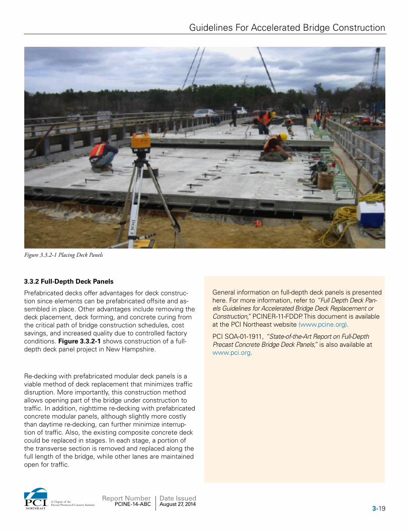
Figure 3.3.2-1 Placing Deck Panels
3.3.2 Full-Depth Deck Panels
Prefabricated decks offer advantages for deck construc-tion since elements can be prefabricated offsite and as-sembled in place. Other advantages include removing the deck placement, deck forming, and concrete curing from the critical path of bridge construction schedules, cost savings, and increased quality due to controlled factory conditions. Figure 3.3.2-1 shows construction of a full-depth deck panel project in New Hampshire.
General information on full-depth deck panels is presented here. For more information, refer to “Full Depth Deck Pan-els Guidelines for Accelerated Bridge Deck Replacement or Construction,” PCINER-11-FDDP. This document is available at the PCI Northeast website (www.pcine.org).
PCI SOA-01-1911, “State-of-the-Art Report on Full-Depth Precast Concrete Bridge Deck Panels,” is also available at www.pci.org.
Re-decking with prefabricated modular deck panels is a viable method of deck replacement that minimizes traffic disruption. More importantly, this construction method allows opening part of the bridge under construction to traffic. In addition, nighttime re-decking with prefabricated concrete modular panels, although slightly more costly than daytime re-decking, can further minimize interrup-tion of traffic. Also, the existing composite concrete deck could be replaced in stages. In each stage, a portion of the transverse section is removed and replaced along the full length of the bridge, while other lanes are maintained open for traffic.
3-19NORTHEAST
A Chapter of thePrecast/Prestressed Concrete Institute
Report Number PCINE-14-ABC
Date Issued August 27, 2014
Guidelines For Accelerated Bridge Construction
3.3.3 Partial-Depth Deck Panels
In situations where a cast-in-place deck will be neces-sary, precast partial-depth deck concrete panels may be used to save time during construction. These panels do not require the extensive shoring and carpentry that conventional wood forms require, nor do they need to be removed once the deck has cured.
General information on partial depth deck panels is pre-sented here. For more information, refer to “Precast Deck Panel Guidelines,” PCINER-01-PDPG. This document is available at the PCI Northeast website (www.pcine.org).
3.4 Proprietary Bridge SystemsThe use of proprietary bridge systems can be considered with approval from the bridge agency.
3.5 Bridge Railing And Parapets
The designer should use parapet and/or rail systems that meet the owner agency’s requirements. The FHWA and the AASHTO LRFD Bridge Design Specifications require that railing and parapet systems be crash tested.
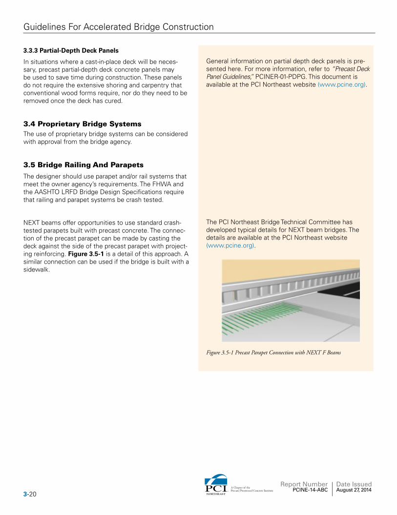
NEXT beams offer opportunities to use standard crash-tested parapets built with precast concrete. The connec-tion of the precast parapet can be made by casting the deck against the side of the precast parapet with project-ing reinforcing. Figure 3.5-1 is a detail of this approach. A similar connection can be used if the bridge is built with a sidewalk.
The PCI Northeast Bridge Technical Committee has developed typical details for NEXT beam bridges. The details are available at the PCI Northeast website (www.pcine.org).
Figure 3.5-1 Precast Parapet Connection with NEXT F Beams
3-20 NORTHEAST
A Chapter of thePrecast/Prestressed Concrete Institute
Report Number PCINE-14-ABC
Date Issued August 27, 2014
Guidelines For Accelerated Bridge Construction
Section 4: Joints
Guidelines Commentary
4.1 General
Joints fall under two categories. The first are structural connections that transmit moment, axial, or shear forces between elements. The second are non-structural con-nections that may be used for thermal movements or to separate discrete portions of the structure (e.g., abutment to wingwall joint).
4.2 Layout of Joints
In general, the designer should show proposed layout plans of all joints that form connections in the structure. This layout plan will be used as a guide to determine sizes of elements and general construction sequencing.
Full-height elements with vertical joints are typically pre-ferred over elements that are “stacked” with horizontal joints. However, horizontal joints may be incorporated in a design if the weight or size of the pieces is excessive.
The designer should include contract provisions that allow different joint configurations within contract defined boundary conditions.
Locations and configuration of joints should be the con-tractor’s option based on boundary conditions set by the designer.
Examples of boundary conditions are as follows:• The designer may specify that a vertical joint be
placed away from bearing locations.• The designer may specify a minimum width of ele-
ments.• Stage construction joint locations may need to be
specific.
4.3 Joint Width and Tolerance
(Ref: PCINE Sheets SUB-6 & 10)
The width of joints is set based on several factors:
1. The tolerance of the two joined elements,2. The erection tolerance of the two joined elements.3. The minimum joint width required to insert the filler
material.Knowing these values, the design engineer can specify a joint width and a joint width tolerance. The following sec-tions contain recommended equations for use in deter-mining joint widths.
4-21NORTHEAST
A Chapter of thePrecast/Prestressed Concrete Institute
Report Number PCINE-14-ABC
Date Issued August 27, 2014
Guidelines For Accelerated Bridge Construction
4.3.1 Vertical Joints
(Ref: PCINE Sheet SUB-10)
The width of vertical joints needs to account for the following:1. The possibility that one or both of the adjacent
elements will be fabricated wider or longer than detailed, but within the specified element tolerance.
2. The possibility that one or both of the adjacent ele-ments will be erected closer together than detailed but within the specified erection tolerance.
3. The minimum width of the joint must accommo-date the joint filler material after all tolerances are accounted for.
Based on this, the minimum required joint width specified on the plans would be the absolute minimum tolerable joint width plus the half the width tolerance of the two adjacent elements plus the erection tolerance of the two adjoining elements.
The equation for the specified vertical joint width would be:
Wj = Wmin + 1/2*(wtl + wtr) + (ehtl + ehtr)
Where: Wj = specified joint widthWmin = minimum tolerable joint widthwtl = width tolerance of left elementwtr = width tolerance of right element ehtl = horizontal erection tolerance of left elementehtr = horizontal erection tolerance of right element
Using the same logic, the joint width tolerance would be the half the width tolerance of the two adjacent elements plus the erection tolerance of the two adjoining elements.
Tjw = Joint width tolerance
= ± (1/2*(wtl + wtr) + (ehtl + ehtr))
Using these equations, the joint width shown on the plans should be the specified joint width ± the joint width tolerance. For example: 11/2" ± 3/4".
Half of the width tolerance is used for each element assuming that the over width would be taken up half on each side of the element.
The PCI Northeast Bridge Technical Committee has developed recommended element fabrication tolerances and element erection tolerances. The committee has also developed details for typical joints based on these equations. See Sheet SUB-10.
4-22 NORTHEAST
A Chapter of thePrecast/Prestressed Concrete Institute
Report Number PCINE-14-ABC
Date Issued August 27, 2014
Guidelines For Accelerated Bridge Construction
4.3.2 Horizontal Joints
(Ref: PCINE Sheet SUB-6)
The width of horizontal joints is slightly different than ver-tical joints. Unlike horizontal layout measurements, verti-cal layout is not normally based on offsets from working lines. This is due to the fact that most bridge structures are made up of only a few stacked elements. The more common way to specify vertical layout is to specify the top elevation of the element within a specified elevation tolerance. When the element is set, the top of the up-per element will be checked for elevation. The thickness (width) of the lower connection is adjusted to accommo-date the elevation tolerance of the lower element and the height of the upper element.
The thickness (width) of horizontal joints needs to account for the following:
1. The possibility that upper elements will be fabri-cated taller than detailed, but within the specified element tolerance.
2. The possibility that the lower element will be erected too high but within the specified elevation tolerance.
3. The possibility that the upper element will be erected too high but within the specified elevation tolerance.
4. The minimum thickness (width) of the joint must accommodate the joint filler material after all toler-ances are accounted for.
Based on this, the minimum required joint width specified on the plans would be the absolute minimum tolerable joint width plus the total height tolerance of the upper element plus the vertical erection tolerance of the up-per element. The total height tolerance is used since the lower joint will be required to accommodate the entire over-height tolerance of the upper element.
The equation for the specified horizontal joint thickness would be:
Tj = Tmin + htu + evtl + evtu
Where:
Tj = specified joint thicknessTmin = minimum tolerable joint thicknesshtu = height tolerance of upper elementevtl = vertical erection tolerance of lower elementevtu = vertical erection tolerance of upper element
Elevation check should be specified and measured at the center of the connection, not necessarily all areas of the top surface. For instance, if a footing is to support a col-umn, the elevation tolerance only needs to be checked at the center of the column, not the corners of the footing.
The PCI Northeast Bridge Technical Committee has developed recommended element fabrication tolerances and element erection tolerances. The committee has also developed details for typical joints based on these equations (see Sheet SUB-6).
4-23NORTHEAST
A Chapter of thePrecast/Prestressed Concrete Institute
Report Number PCINE-14-ABC
Date Issued August 27, 2014
Guidelines For Accelerated Bridge Construction
Using the same logic, the joint thickness tolerance would be the height tolerance of the upper elements plus the vertical erection tolerance of the two adjoining elements.
Tjt = Joint thickness tolerance
= + (htu + evtl + evtu)
Using these equations, the joint width shown on the plans should be the specified joint width ± the joint width tolerance. For example: 11/2" ± 3/4".
4.4 Structural Joints
4.4.1 Moment Connections
Elements can be connected with a joint that can transmit moment and shear using the following methods:
4.4.1.1 Embedded Mechanical Splicers
(Ref: PCINE Sheet SUB-5)
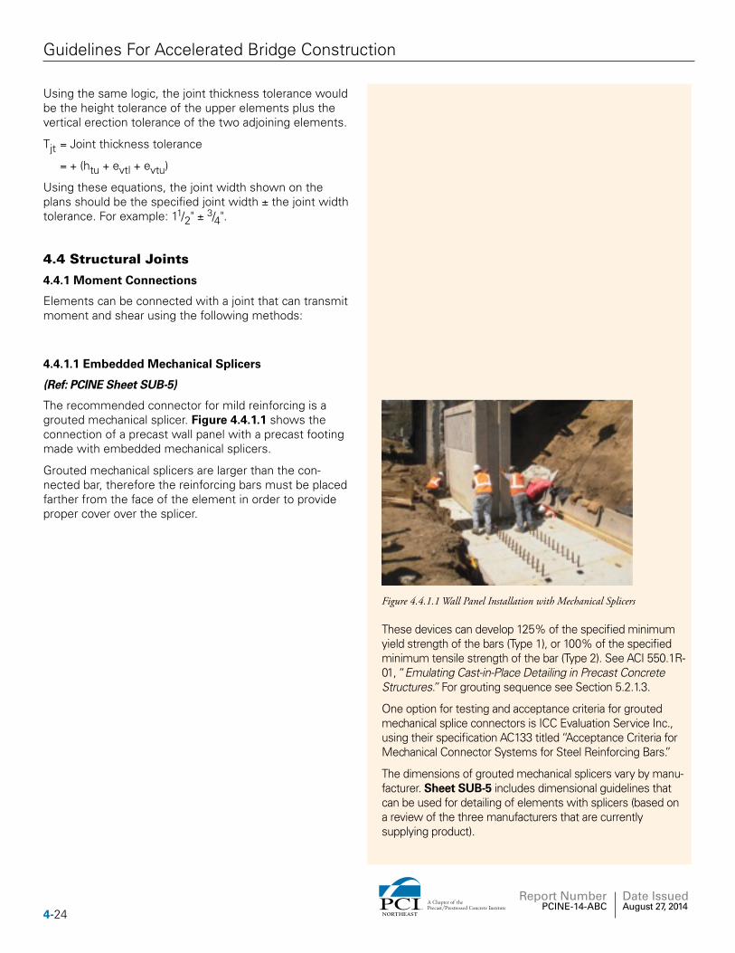
The recommended connector for mild reinforcing is a grouted mechanical splicer. Figure 4.4.1.1 shows the connection of a precast wall panel with a precast footing made with embedded mechanical splicers.
Grouted mechanical splicers are larger than the con-nected bar, therefore the reinforcing bars must be placed farther from the face of the element in order to provide proper cover over the splicer.
Figure 4.4.1.1 Wall Panel Installation with Mechanical Splicers
These devices can develop 125% of the specified minimum yield strength of the bars (Type 1), or 100% of the specified minimum tensile strength of the bar (Type 2). See ACI 550.1R-01, “Emulating Cast-in-Place Detailing in Precast Concrete Structures.” For grouting sequence see Section 5.2.1.3.
One option for testing and acceptance criteria for grouted mechanical splice connectors is ICC Evaluation Service Inc., using their specification AC133 titled “Acceptance Criteria for Mechanical Connector Systems for Steel Reinforcing Bars.”
The dimensions of grouted mechanical splicers vary by manu-facturer. Sheet SUB-5 includes dimensional guidelines that can be used for detailing of elements with splicers (based on a review of the three manufacturers that are currently supplying product).
4-24 NORTHEAST
A Chapter of thePrecast/Prestressed Concrete Institute
Report Number PCINE-14-ABC
Date Issued August 27, 2014
Guidelines For Accelerated Bridge Construction
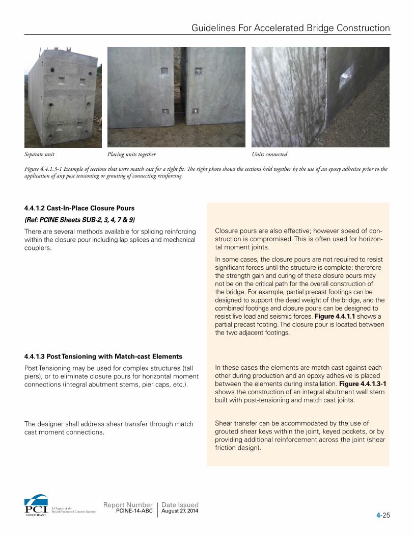
Separate unit
Figure 4.4.1.3-1 Example of sections that were match cast for a tight fit. The right photo shows the sections held together by the use of an epoxy adhesive prior to the application of any post tensioning or grouting of connecting reinforcing.
Placing units together Units connected
4.4.1.2 Cast-In-Place Closure Pours
(Ref: PCINE Sheets SUB-2, 3, 4, 7 & 9)
There are several methods available for splicing reinforcing within the closure pour including lap splices and mechanical couplers.
Closure pours are also effective; however speed of con-struction is compromised. This is often used for horizon-tal moment joints.
In some cases, the closure pours are not required to resist significant forces until the structure is complete; therefore the strength gain and curing of these closure pours may not be on the critical path for the overall construction of the bridge. For example, partial precast footings can be designed to support the dead weight of the bridge, and the combined footings and closure pours can be designed to resist live load and seismic forces. Figure 4.4.1.1 shows a partial precast footing. The closure pour is located between the two adjacent footings.
4.4.1.3 Post Tensioning with Match-cast Elements
Post Tensioning may be used for complex structures (tall piers), or to eliminate closure pours for horizontal moment connections (integral abutment stems, pier caps, etc.).
In these cases the elements are match cast against each other during production and an epoxy adhesive is placed between the elements during installation. Figure 4.4.1.3-1 shows the construction of an integral abutment wall stem built with post-tensioning and match cast joints.
The designer shall address shear transfer through match cast moment connections.
Shear transfer can be accommodated by the use of grouted shear keys within the joint, keyed pockets, or by providing additional reinforcement across the joint (shear friction design).
4-25NORTHEAST
A Chapter of thePrecast/Prestressed Concrete Institute
Report Number PCINE-14-ABC
Date Issued August 27, 2014
Guidelines For Accelerated Bridge Construction
4.4.2 Shear Connections
Certain elements may need to be connected with a joint that only transmits shear using the following methods:
4.4.2.1 Vertical Grouted Keys in Wall Panels
(Ref: PCINE Sheet SUB-10)
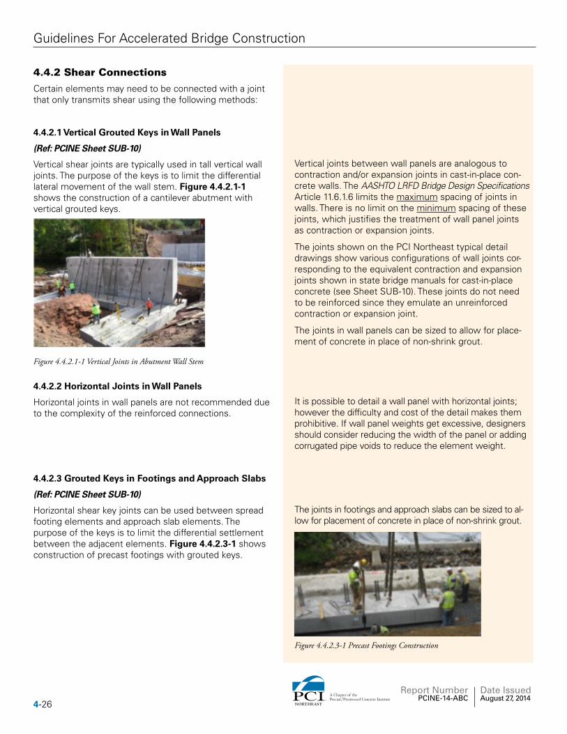
Vertical shear joints are typically used in tall vertical wall joints. The purpose of the keys is to limit the differential lateral movement of the wall stem. Figure 4.4.2.1-1 shows the construction of a cantilever abutment with vertical grouted keys.
Figure 4.4.2.1-1 Vertical Joints in Abutment Wall Stem
Vertical joints between wall panels are analogous to contraction and/or expansion joints in cast-in-place con-crete walls. The AASHTO LRFD Bridge Design Specifications Article 11.6.1.6 limits the maximum spacing of joints in walls. There is no limit on the minimum spacing of these joints, which justifies the treatment of wall panel joints as contraction or expansion joints.
The joints shown on the PCI Northeast typical detail drawings show various configurations of wall joints cor-responding to the equivalent contraction and expansion joints shown in state bridge manuals for cast-in-place concrete (see Sheet SUB-10). These joints do not need to be reinforced since they emulate an unreinforced contraction or expansion joint.
The joints in wall panels can be sized to allow for place-ment of concrete in place of non-shrink grout.
4.4.2.2 Horizontal Joints in Wall Panels
Horizontal joints in wall panels are not recommended due to the complexity of the reinforced connections.
It is possible to detail a wall panel with horizontal joints; however the difficulty and cost of the detail makes them prohibitive. If wall panel weights get excessive, designers should consider reducing the width of the panel or adding corrugated pipe voids to reduce the element weight.
4.4.2.3 Grouted Keys in Footings and Approach Slabs
(Ref: PCINE Sheet SUB-10)
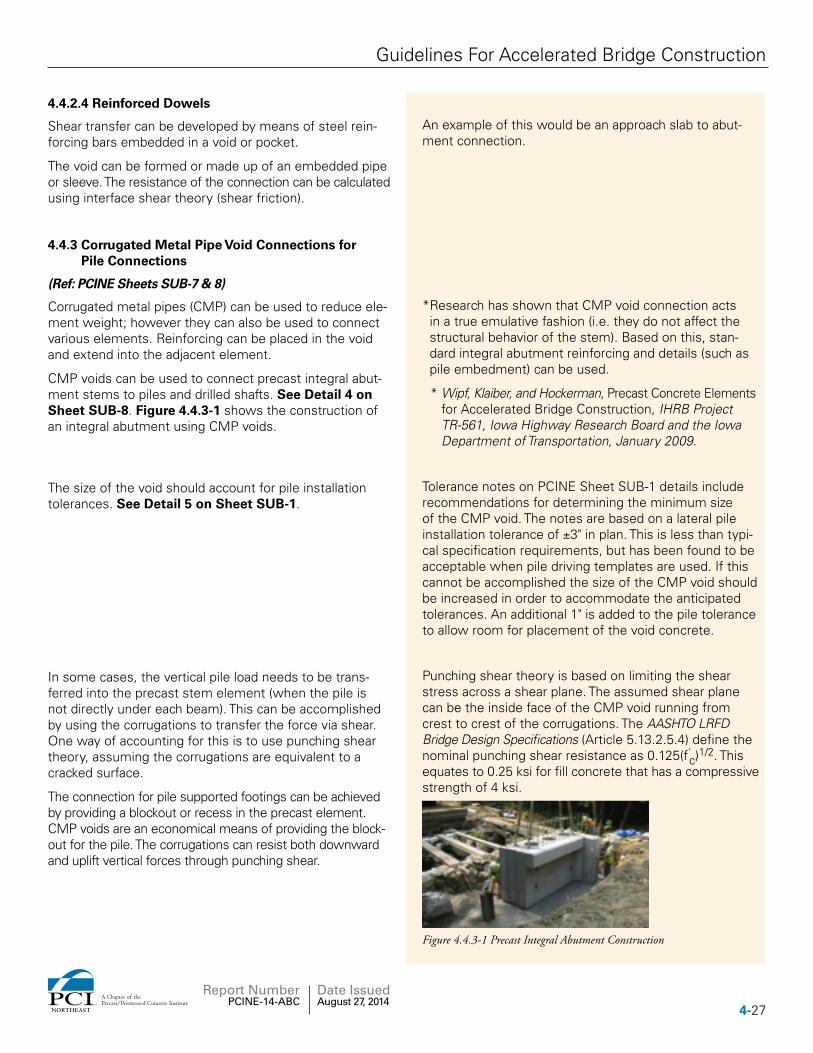
Horizontal shear key joints can be used between spread footing elements and approach slab elements. The purpose of the keys is to limit the differential settlement between the adjacent elements. Figure 4.4.2.3-1 shows construction of precast footings with grouted keys.
The joints in footings and approach slabs can be sized to al-low for placement of concrete in place of non-shrink grout.
Figure 4.4.2.3-1 Precast Footings Construction
4-26 NORTHEAST
A Chapter of thePrecast/Prestressed Concrete Institute
Report Number PCINE-14-ABC
Date Issued August 27, 2014
Guidelines For Accelerated Bridge Construction
4.4.2.4 Reinforced Dowels
Shear transfer can be developed by means of steel rein-forcing bars embedded in a void or pocket.
The void can be formed or made up of an embedded pipe or sleeve. The resistance of the connection can be calculated using interface shear theory (shear friction).
An example of this would be an approach slab to abut-ment connection.
4.4.3 Corrugated Metal Pipe Void Connections for Pile Connections
(Ref: PCINE Sheets SUB-7 & 8)
Corrugated metal pipes (CMP) can be used to reduce ele-ment weight; however they can also be used to connect various elements. Reinforcing can be placed in the void and extend into the adjacent element.
CMP voids can be used to connect precast integral abut-ment stems to piles and drilled shafts. See Detail 4 on Sheet SUB-8. Figure 4.4.3-1 shows the construction of an integral abutment using CMP voids.
* Research has shown that CMP void connection acts in a true emulative fashion (i.e. they do not affect the structural behavior of the stem). Based on this, stan-dard integral abutment reinforcing and details (such as pile embedment) can be used.
* Wipf, Klaiber, and Hockerman, Precast Concrete Elements for Accelerated Bridge Construction, IHRB Project TR-561, Iowa Highway Research Board and the Iowa Department of Transportation, January 2009.
The size of the void should account for pile installation tolerances. See Detail 5 on Sheet SUB-1.
Tolerance notes on PCINE Sheet SUB-1 details include recommendations for determining the minimum size of the CMP void. The notes are based on a lateral pile installation tolerance of ±3" in plan. This is less than typi-cal specification requirements, but has been found to be acceptable when pile driving templates are used. If this cannot be accomplished the size of the CMP void should be increased in order to accommodate the anticipated tolerances. An additional 1" is added to the pile tolerance to allow room for placement of the void concrete.
In some cases, the vertical pile load needs to be trans-ferred into the precast stem element (when the pile is not directly under each beam). This can be accomplished by using the corrugations to transfer the force via shear. One way of accounting for this is to use punching shear theory, assuming the corrugations are equivalent to a cracked surface.
The connection for pile supported footings can be achieved by providing a blockout or recess in the precast element. CMP voids are an economical means of providing the block-out for the pile. The corrugations can resist both downward and uplift vertical forces through punching shear.
Punching shear theory is based on limiting the shear stress across a shear plane. The assumed shear plane can be the inside face of the CMP void running from crest to crest of the corrugations. The AASHTO LRFD Bridge Design Specifications (Article 5.13.2.5.4) define the nominal punching shear resistance as 0.125(f'c)1/2. This equates to 0.25 ksi for fill concrete that has a compressive strength of 4 ksi.
Figure 4.4.3-1 Precast Integral Abutment Construction
4-27NORTHEAST
A Chapter of thePrecast/Prestressed Concrete Institute
Report Number PCINE-14-ABC
Date Issued August 27, 2014
Guidelines For Accelerated Bridge Construction
4.4.3.1 Corrugated Metal Pipe Void Connections for Wall Cap Connections
(Ref: PCINE Sheet SUB-6)
Corrugated metal pipe voids can be used to provide nominal capacity moment and shear connections be-tween wall panels and a precast concrete cap. This can be accomplished by placing reinforcing bars within the void concrete at the interface area between the two elements.
This connection is easier and less costly when compared to a connection made with grouted mechanical splicers. CMP voids allow for larger element and installation toler-ances in the wall panels.
The design of the connection can be made using standard reinforced concrete bending and shear theory.
4.4.4 Deck Panel Connections
Connections of full-depth deck panels are generally split into two categories; connections between adjoining pan-els, and connections of panels to the beams and girders. These are described below:
The PCI Northeast Bridge Technical Committee has pub-lished details and guidelines for the design and detailing of full-depth deck panels (PCINER-11-FDDP, 2nd Edition, 2011). The document includes information on joints and connections. The following sections outline the typical types of connections used in deck panel bridges.
4.4.4.1 Panel to Panel Connections
There are two categories of deck panel connections. Lon-gitudinal joints typically run parallel to the beam framing. Transverse joints typically run perpendicular to the beam framing, or along the bridge skew.
Longitudinal joints are necessary to accommodate a change in the cross slope, or when the panel installation is phased. Since this connection is typically made in the direction of the primary forces (i.e., the design reinforcing is perpendicular to the beams), the joint is designed to re-sist these applied forces. These connections are typically field cast closure pours between the panels. Mild rein-forcing is extended from ends of each panel and a cast-in-place pour made to connect the panels. It is important to properly develop the projecting reinforcing in the closure pour area. This can be done with lapped bars, hooked bars, or headed reinforcing bars.
Some state agencies have tested and used ultra-high performance concrete (UHPC) joints. The UHPC joints typically consist of straight or hooked reinforcing bars extending a short distance from the face of the panels into the UHPC to make the cast-in-place closure pour.
Transverse connections are necessary to provide continuous action between panels. The joint should be capable of trans-ferring shear and bending moment between adjacent panels. The AASHTO LRFD Bridge Design Specifications recom-mends the use of grouted shear keys that are subsequently post tensioned longitudinally between end closure pours.
The AASHTO LRFD Bridge Design Specifications Section 9.7.5 recommends that the minimum average effective prestress force not be less than 250 psi (applied to the contact area of the joint).
The most common details make use of full depth female-to-female type joints. The joint has a wider opening at the top and nearly closed at the bottom with a polyethylene backer rod to form the bottom of the shear key. The joints are post tensioned longitudinally at mid depth.
4-28 NORTHEAST
A Chapter of thePrecast/Prestressed Concrete Institute
Report Number PCINE-14-ABC
Date Issued August 27, 2014
Guidelines For Accelerated Bridge Construction
4.4.4.2 Connections of Full-Depth Deck Panels to Beams and Girders
Almost all bridges are designed for composite action be-tween the beam and the deck. For full-depth deck panels, composite action is achieved by incorporating welded shear studs (steel beams) or projecting reinforcing (con-crete beams) into blockouts or shear pockets detailed into the precast panels.
4.4.5 Connections between Adjacent Beams with Integral Full-Depth Decks
NEXT-D beams and deck bulb tee beams include full-depth integral decks. These beams require a connection between the adjacent deck flanges. This connection needs to be designed to resist the bending and shear forces that are generated by truck wheel loads.
The design of the connection can be based on the same design principles as a cast-in-place concrete deck. The most common design method is the “strip method” as defined in the AASHTO LRFD Bridge Design Specifications (Article 4.6.2.1).
The deck flange connection is normally made using a grouted or concreted closure pour that includes reinforc-ing steel.
There are various methods to detail a closure pour be-tween adjacent beams. Each method makes use of rein-forcing steel combined with either grout or concrete that resists the forces acting on the deck at the connection. Several different closure pour connection details have been developed and implemented in the United States. Some connections are based on normal reinforcing bar development equations that are included in the AASHTO LRFD Bridge Design Specifications. These include:
1. Lapped reinforcing bars with concrete – This connec-tion uses standard lapped bar details. The concrete can be normal concrete or high early strength con-crete depending on the schedule for the project.
2. Hooked reinforcing bars with concrete – This connection is similar to the lapped reinforcing bar detail except standard hooked bars are used to reduce the width of the closure pour.
Other connections are based on recent research that was based on reducing the width of the closure pour joint. These include:
1. Headed and hooked reinforcing bars with high-strength grout or high-strength concrete: Research has shown that headed and hooked reinforcing steel bar splices can be developed in high-strength concrete joints by using short non-contact lap splic-es (Cast-in-Place Concrete Connections for Precast Deck Systems, NCHRP Web only Document 173 (Final Report for Project 10-71), National Cooperative Highway Research Program, 2011).
4-29NORTHEAST
A Chapter of thePrecast/Prestressed Concrete Institute
Report Number PCINE-14-ABC
Date Issued August 27, 2014
Guidelines For Accelerated Bridge Construction
2. Straight and hooked reinforcing bars with Ultra-High Performance Concrete (UHPC): Initial research has shown that reinforcing bars can be connected using short lap splices of hooked and straight bars placed in UHPC joints (Behavior of Field-Cast Ultra-High Perfor-mance Concrete Bridge Deck Connections Under Cy-clic and Static Structural Loading, U.S. Department of Transportation, Federal Highway Administration, FHWA Publication No. FHWA-HRT-11-023).
4.5 Non-Structural Joints
Typical non-structural joints include expansion joints and contraction joints. These are joints that do not have reinforc-ing passing through them and are not counted on to transfer forces across the joint. Figure 4.4.2.1-1 shows construction of a precast abutment with vertical contraction joints.
Examples of non-structural joints include retaining wall expansion and contraction joints, joints between differ-ent substructure units (abutment to wingwall interface), and joints in long pier bents (where effects of thermal movement can cause large internal frame forces).
In most cases, these joints should be sealed to prevent moisture from penetrating the area between elements where freezing action could spall the adjacent elements. In some cases, the joints can be left open.
Non-structural joints may also be desirable between substructure sections that may potentially experience differential settlement. An example of this would be the interface between a pile supported integral abutment and a long u-shaped wingwall supported on spread footings.
Sealing of the joint can be accomplished by injecting a foam sealant in the opening. The rear face of the wall may be sealed with a membrane sheet, however foam fill is recommended near the ground line or water line. Grouting is also an acceptable option. See Section 5.3.
4-30 NORTHEAST
A Chapter of thePrecast/Prestressed Concrete Institute
Report Number PCINE-14-ABC
Date Issued August 27, 2014
Guidelines For Accelerated Bridge Construction
Section 5: Grouting
Guidelines Commentary5.1 Sub-Footings
Cast-in-place (CIP) concrete sub-footing may be used for construction on uneven surfaces, such as bedrock. Sub-footings are used to provide a relatively flat work surface for the placement of precast footings. Individual sub-footings may be used at each leveling screw location as opposed to a continuous full width sub-footing.
The sides of the sub-footing pours need not be formed. The concrete may be cast against the excavation.
The sub-footing material should be designed to support the loads of the leveling screws. Steel plates can be used to accommodate the leveling screw point loads.
See Detail 4 on Sheet SUB-7 for a suggested Leveling Screw Detail.
5.2 Fill under Spread footings
(Ref: PCINE Sheet SUB-7)
The area below a precast footing needs to be filled with a material that can transfer the footing bearing pressures to the sub-grade below. Bearing pressures under footings are relatively low, in the range of 25 psi to 75 psi. It is recommended that flowable fill be placed under footings, which is a relatively low strength mix of sand, water and cement that can fill the void below the footing, while providing adequate strength. Grouts can be used if high early strength gain is required; however the cost is higher than flowable fill.
The bearing pressure noted corresponds to roughly 4 ksf to 11 ksf.
Placement of the fill material can be accomplished by pumping or pouring into spaced vertical holes within the precast footing starting from the center and working toward the extremities.
After the fill material has reached a compressive strength that is sufficient to support the footing, the leveling screws, if used can be removed and the fill holes can be grouted.
See Section 3.1.2.5 for more information on grouting under footings.
It is recommended that the spacing of the holes be no greater than 6 feet. If pressure grouting is the chosen method of filling this void, the operation must be moni-tored to ensure the footing is not lifted. A dam around the perimeter of the footing should be used to create a hydraulic head which will facilitate the flow of grout and retain the fill material.
5-31NORTHEAST
A Chapter of thePrecast/Prestressed Concrete Institute
Report Number PCINE-14-ABC
Date Issued August 27, 2014
Guidelines For Accelerated Bridge Construction
5.3 Element to Element grouting
It is the contractor’s responsibility to determine the specific type of grout to be used in each joint, and the methods of installation based on the notes on the plans and in the specifications.
The assembly plan developed by the contractor should specify the type of grout and method of installation for each joint. See Section 7.3.
A prepackaged, shrinkage-compensating, flowable grout is recommended for most connections. The strength of the grout should be equal to or greater than the strength of the joined elements.
The designer should include a note on the plans or in the specifications describing the required properties of the grout in each connection.
5.3.1 Horizontal Surfaces
5.3.1.1 Recessed Key Connection
(Ref: PCINE Sheet SUB-5, 9 & 10)
This joint is typically found at the stem/footing joint in abutments. Use of a recessed key will improve the shear capacity and will create adequate head to help push a flowable grout through the joint minimizing the need to pump the grout into place. Detail 4 on Sheet SUB-9 shows an example of the recessed key.
The grout within this joint must transfer the compressive load of the stem-to-footing moment couple in resisting overturning loads in the connection. Grout also can pro-vide some measure of corrosion protection for the con-nections within the joint. This joint is typically found in horizontal connections between elements where there is significant load transfer. This grout may take many forms including prepackaged grout, dry pack, pre-placed prepackaged mortar (buttered), or grout placed under pressure.
The use of prepackaged grout is recommended. The compressive strength of the grout should meet or ex-ceed the strength of the concrete in the wall and footing.
The recommended grouting procedure for recessed key connections is as follows (see Detail 6 on Sheet SUB-5):
Step 1: Fill the key to just below the lower port of the grouted mechanical splice. A recessed keyway or grout dam may be used to create a hydraulic head for grout flow. The grout may be installed by pouring the grout into the keyway slot or behind the grout dam until the inlet side will accept no more grout. This procedure should be started at the end of the joint and proceed continuously along the joint.
Filling this joint from both sides and both ends simul-taneously will increase the chance for a void within the key. Pumping the grout into place should be encouraged as it supplies a continuous flow of grout making it easier to maintain a continuous flow through the key.
The grout placed in step 1 shall be kept out of the me-chanical splice by the use of a washer or stopper that is supplied by the mechanical splice manufacturer.
Washers placed over the rebar extensions provide the seal to keep the mechanical splice free of step 1 grout.
5-32 NORTHEAST
A Chapter of thePrecast/Prestressed Concrete Institute
Report Number PCINE-14-ABC
Date Issued August 27, 2014
Guidelines For Accelerated Bridge Construction
Step 2: Grout the mechanical splice per manufacturer’s recommendations.
Step 3: Fill the remainder of the key.
The recommended grouting procedure for non- recessed key connections is shown on Detail 5 on Sheet SUB-5.
This connection does not use a key. If shear and/or com-pression transfer is required through the grout. The grout should be a non-shrink material.
The grout placed within this type of joint should also pro-vide protection from the elements and as such, if the joint is open to the weather, water shedding detailing should be employed.
Other methods of grouting have been used successfully. The project specifications should allow for contractor alternate grouting procedures. The procedures should ensure that the key grout does not flow into the grout mechanical splice.
The designer should choose the most appropriate type of grout for the anticipated exposure conditions.
5.3.2 Vertical Joints
(Ref: PCINE Sheet SUB-10)
A flowable, cementitious grout should be used for vertical joints. It should be introduced at the top of the joint, filling it from bottom to top.
Designers should specify the use of rigid formwork for the joints and rodding of grout during installation to mini-mize voids.
This joint is typically found between vertical wall ele-ments. Significant hydraulic head will be created due to the typical height of the joints being filled. Backer rods placed at the edges of the enclosed vertical joint as a dam against the fluid grout will not be adequate in restraining the grout due to the fluid pressure. It is recommended that such a joint be restrained with formwork in most cases. The grout should be rodded during placement to ensure that voids are eliminated.
If shear transfer is not required, consider filling this joint with expanding foam sealant or other fillers.
This treatment may be considered adequate if the joint is deemed non-structural. The expanding foam keeps the joint free of foreign material and should be supple-mented with a flexible joint sealant (both sides) and membrane on the fill side for waterproofing.
Pre-applied rigid joint filler materials are not recommended. Inserting rigid fillers after assembly is also not recommended.
Experience has shown that tolerance between the elements will be compromised, which makes element assembly virtually impossible. Installation of fillers after assembly results in a poor quality joint.
5-33NORTHEAST
A Chapter of thePrecast/Prestressed Concrete Institute
Report Number PCINE-14-ABC
Date Issued August 27, 2014
Guidelines For Accelerated Bridge Construction
5.3.3 Mechanical Grouted Splices
(Ref: PCINE Sheet SUB-5)
Sheet SUB-5 (Detail 8) contains information on the installation and grouting of Mechanical Grouted Splices.
Only grout specified by the mechanical splice manufacturer should be used.
The grout used in the sleeves is part of the splice “system.” The grouts used in the sleeves must be the same grout used for certification tests.
The type of grouting operation is usually dependent on the orientation of the sleeve. A training session on proper grouting techniques is recommended for field personnel.
A sleeve cast in the upper element is a post-grouted connection. Manufacturer recommendations shall be followed.
The manufacturer will typically require special equipment to mix and install the grout.
A sleeve cast in the lower element can be filled with grout from the top and the ports are plugged after the sleeve has been purged of air. The upper element is low-ered into position and the bars extending from the ele-ment are pushed into the sleeve displacing the grout into the surrounding joint. Sleeves in this position can also be grouted after setting the elements using ports.
The text above is for typical installations. The sleeves are proprietary and each company will have different varia-tions for these grouting procedures.
Experience has shown that the grouting procedure is easily mastered by construction crews after a few sleeves. Based on this, it is recommended that design engineers specify a test mock-up connection with a mini-mum four sleeves.
5.4 Pile and Wall Caps
(Ref: PCINE Sheet SUB-6, 7 & 8)
Self-consolidating concrete is recommended to fill the void. The concrete should either have limited shrinkage characteristics or be made with a shrinkage-compensat-ing admixture.
These connections are typically at integral abutment caps, pile bent caps, or pile supported footings. Self-con-solidating concrete can be used for caps with small fill and vent ducts to ensure adequate consolidation without segregation.
5-34 NORTHEAST
A Chapter of thePrecast/Prestressed Concrete Institute
Report Number PCINE-14-ABC
Date Issued August 27, 2014
Guidelines For Accelerated Bridge Construction
The concrete should be placed through fill ducts into pile blockouts. Vent ducts shall also be provided into the blockout. When fill and vent ducts are used they should be corrosion resistant (PVC or galvanized steel). At least one fill and one vent duct should penetrate into each pile blockout. See Detail 4 on Sheet SUB-6.
Having two ducts per blockout allows for concrete to be placed in one duct, while placement is being monitored in the other duct.
5.5 Post-Tensioning Ducts
Grouting of post-tensioning ducts should be done using a grout designed for pressure grouting the annular spaces around post-tensioning bars or cables.
Post-tensioning ducts are proprietary items designed to fit a particular post-tensioning system. The system chosen must fit within the construction and do so within normal tolerances.
There are several commercial grouts available that are designed for this purpose. These grouts have been de-signed to be pumped through small annular spaces over long distances without segregating. If a grout is used that has not been designed for this purpose it is likely that the aggregates will segregate and result in plugging the grout ports, lines or pump, and possibly compromis-ing the grouting operation.
Using a corrugated duct in combination with a grout al-lows the post-tensioning tendon to become developed along its length in the event of any loss of end anchorage due to corrosion. The designer should consult with the grout manufacturer to select a duct size that is consis-tent with the recommended grout. In most applications allowing a total of 3/4" of tolerance should be adequate. (For example, using a 3-inch duct for a 13/8" post-tensioning bar)
Special care should be taken for grouting of ducts in either vertical or sinusoidal patterns.
There have been problems with excess bleed water in post-tensioning ducts that have led to severe corrosion of the tendons. The following publications are recom-mended resources for more information on the proper installation and grouting of post-tensioning systems:
FHWA, “Post-Tensioning Tendon Installation and Grouting Manual,” (FHWA-NHI-13-026, May 2013)
Post Tensioning Institute, PTI M55.1-12: Specification for Grouting of Post-Tensioned Structures.
5-35NORTHEAST
A Chapter of thePrecast/Prestressed Concrete Institute
Report Number PCINE-14-ABC
Date Issued August 27, 2014
Guidelines For Accelerated Bridge Construction
5.6 Blockouts for Anchoring Devices
Blockouts are used to recess bolting mechanisms such as those for post-tensioning strands in butted beam decks or for the anchoring bolts in precast rail. All open block-outs on the structure should be filled with a prepackaged non-shrink grout specifically formulated for the intended orientation of the work (horizontal, vertical, or overhead). First ensure the recess is free of dust and other construc-tion debris by cleaning the area according to the grout manufacturer’s recommendations. Apply the grout using a trowel into the recess in layers to ensure the cavity is completely filled. The final layer shall be troweled smooth with the face of the element. The grout color and texture shall closely match the element.
5-36 NORTHEAST
A Chapter of thePrecast/Prestressed Concrete Institute
Report Number PCINE-14-ABC
Date Issued August 27, 2014
Guidelines For Accelerated Bridge Construction
Section 6: Seismic Considerations
Guidelines Commentary6.1 General Criteria
In general, the design and details of precast concrete elements for seismic forces should be consistent with cast-in-place concrete construction.
All provisions specified in AASHTO need to be satisfied in a precast concrete bridge. This includes but is not limited to reinforcing steel in footings, column confine-ment, and connections between the superstructure and substructure.
The process of designing seismic reinforcement is the same as for a cast-in-place concrete structure. Slight variations in detailing may be required because of the use of precast elements. These issues are covered in this section.
6.2 Connection of Superstructure to Substructure
There are several methods of transmitting seismic hori-zontal loads from the superstructure to the substructure. In most cases this consists of designing the connection between the stringers to the substructure to also resist the seismic horizontal loads. This section discusses some of the other options that are typically used.
In many states, the connection of the superstructure to the substructure is detailed as a pinned connection. Inte-gral (moment) connections are also commonly used.
There are other options for seismic restraint such as cable restrainers and seismic isolation devices. These methods are also acceptable; however they are not included in this document.
6.2.1 Keeper Blocks
Keeper blocks consist of reinforced concrete blocks that are placed between two interior beams to transmit lateral forces from the superstructure to the substructure. Keeper blocks are often the most cost-effective means of restraining a bridge for seismic events.
Keeper blocks are used to resist lateral seismic forces. Longitudinal seismic forces can be resisted by the abut-ment backwall, or anchor rods.
Bridges should be designed with only one keeper block per superstructure unit.
Concrete keeper blocks have very low ductility. If two blocks were detailed, it is likely that one would carry all the seismic demand. Distribution of seismic forces to other keeper assemblies would most likely only occur after failure of the first keeper.
6-37NORTHEAST
A Chapter of thePrecast/Prestressed Concrete Institute
Report Number PCINE-14-ABC
Date Issued August 27, 2014
Guidelines For Accelerated Bridge Construction
If keeper blocks are precast, the connection of keeper blocks can be made using several of the methods outlined in this document.
Consideration should be given for casting keeper blocks in place. See Details on Sheets SUB-2, 3 & 4
Keepers can be installed using grouted mechanical splices, or can be cast integral with the precast substructure element.
6.2.2 Pilasters/Cheekwalls
Pilaster/Cheekwalls are used on adjacent box beam bridges near the fascia beam ends. They resist lateral seismic forces.
The design is similar to keeper blocks. Each pilaster must be capable of resisting the entire lateral seismic force at each substructure unit, since only one pilaster/cheekwall will engage the superstructure at a time.
Pilasters are usually only used on adjacent box beam bridges since there is no gap between adjacent beams. On stringer bridges, keeper blocks are probably more cost effective, since only one keeper is required to resist lateral seismic forces in both directions.
The commentary from Section 6.2.1 is also applicable to this section.
6.2.3 Abutment Backwall
(Ref: PCINE Sheet SUB-9)
Longitudinal seismic forces can be resisted by the abut-ment backwall. The design of abutment backwalls for seismic forces is similar to keeper blocks.
The design of seismic restraining systems is based on lim-ited and repairable damage. Using backwalls for restraint will inevitably result in a structure that has shifted longitu-dinally during the seismic event. The structure may need to be jacked back into position after seismic events.
Designers should verify that the distance between the backwall and the beam/slab is sufficient for thermal move-ment, but small enough so that the beams do not slide off the substructures.
One of the most important aspects of seismic design is to prevent superstructures from sliding off substructures. This issue becomes more pronounced on multiple span bridges where all joints between spans are assumed to be closed in one direction.
6.2.4 Anchor Rods
The design of anchor rods for lateral load should take into account the bending capacity of the rod, edge distance to the concrete foundation, internal reinforcing around the embedded portion, strength of the concrete, and group action of the rods.
The AASHTO specifications do not specifically address the design of embedded anchors loaded in shear. Designing for the shear capacity of the rod is only part of the poten-tial failure mechanism. The rods tend to fail in combined bending and crushing of the concrete around the rod. The AASHTO code refers to this failure mechanism as a “global” failure. AASHTO Article C14.8.3.1 references the American Concrete Institute publication “Building Code Requirements for Structural Concrete” (ACI 318-05), Appendix D, for the investigation of this failure mechanism.
6-38 NORTHEAST
A Chapter of thePrecast/Prestressed Concrete Institute
Report Number PCINE-14-ABC
Date Issued August 27, 2014
Guidelines For Accelerated Bridge Construction
Anchor rods should be designed to be ductile. The use of high-strength, heat-treated rods is discouraged due to low ductility. The embedded portion of the rod shall be properly reinforced in order to prevent brittle fractures of the surrounding concrete.
During a seismic event, it is inevitable that only a percentage of the rods will initially see load due to construction toler-ances. Ductility in the rods will ensure that all rods will work together to resist seismic forces.
The anchor rods should normally be surrounded by lateral reinforcing steel near the surface of the concrete. This will allow lateral forces to be resisted after the initial cracking of the concrete.
Material for anchor rods should be ASTM F1554, and should be either threaded (with nuts) or swaged on the embedded portion of the rod. The design yield strength of this material may be specified as 36 ksi (250 MPa), 55 ksi (380 MPa), or 105 ksi (725 MPa), depending on the design. The yield strength should be given in the specifi-cations or on the plans.
This material is specifically designed for anchor rod appli-cations. Other materials have been used, but do not offer the economies of ASTM F1554. The designer should of-fer options of swaging or threading the anchor as differ-ent suppliers supply one or both of these options.
6.2.5 Integral Connections
(Ref: PCINE Sheet SUB-8)
Superstructures can be connected to substructures using integral moment connections. In most cases, this connec-tion will be made with a cast-in-place closure pour or by using grouted mechanical splices.
The most common form of integral connection is between beams and abutments in stringer bridges. In these cases, the end diaphragm is usually cast in place between the beams due to the complexity of the shapes.
Integral connections have successfully been made between beams and abutments using grouted mechanical splices cast into the beam-ends. It is also common in high seismic regions to make integral connections between the super-structure and piers. These connections are similar to integral abutment connections.
Designers should also refer to individual state require-ments with respect to the design of integral abutments.
6.3 Column Connections
Columns are often the most heavily loaded elements during a seismic event. Special care shall be taken to properly detail connections in precast column elements.
In high seismic regions, columns are designed to form plastic hinges and contribute to dissipation of seismic forces. The high demand region on a typical column is at the ends where the column connects to the footings and pier caps.
6-39NORTHEAST
A Chapter of thePrecast/Prestressed Concrete Institute
Report Number PCINE-14-ABC
Date Issued August 27, 2014
Guidelines For Accelerated Bridge Construction
6.3.1 Column Base and Cap Connections
(Ref: PCINE Sheets SUB-5 & 6)
The use of mechanical splices that can develop 100% of the specified tensile capacity of the connected reinforcing bar is recommended for columns in high seismic zones.
There are two levels of mechanical splice devices speci-fied in the ACI 318 Code. Type 1 mechanical splices need to be capable of developing 125% of the specified mini-mum yield strength of the bar. Type 2 mechanical splices need to be capable of developing 100% of the specified minimum tensile strength of the bar (equal to 150% of specified yield for ASTM A615 bars).
The 125% development is required for all mechanical re-inforcing couplers in the AASHTO specifications. This level of strength is not sufficient for plastic hinge zones that will experience significant ductile behavior. The recommenda-tion is based on the requirements of the ACI 318 Code for Special Moment Frames constructed using precast con-crete. The designer should specify the strength require-ments for the Type 2 connectors in the contract.
According to the current AASHTO code, mechanical splices should be staggered a minimum of 24" for bridges in high seismic zones. (Section 5.10.11.4.1f of the LRFD Specifica-tions). This provision is based on the fact that the AASHTO specifications are limited to Type 1 mechanical splices only.
The current ACI 318 code has similar restrictions for Type 1 mechanical splices; however the use of Type 2 mechanical splices are unrestricted in special moment frames construct-ed with precast concrete (including the plastic hinge zone). For these reasons, it is recommended that designers follow the provisions of ACI 318, Article 21.8 “Special moment frames constructed using precast concrete.” This includes the requirements for determining the length of the plastic hinge region.
One way to avoid having mechanical connectors in the plastic hinge zone is to place all of the mechanical connectors within the footing (see Detail 5 on Sheet SUB-5) and within the pier cap (see Details 2 and 3 on Sheet SUB-6) where plastic hinging is not a factor. While this is possible, it makes handling of the column more difficult, which can lead to higher costs.
The AASHTO specifications for low to moderate seismic zones allow for splicing 100% of the longitudinal bars with mechanical splices at one location. High seismic zones are defined as Zones 3 and 4 in the LRFD Specifications.
6-40 NORTHEAST
A Chapter of thePrecast/Prestressed Concrete Institute
Report Number PCINE-14-ABC
Date Issued August 27, 2014
Guidelines For Accelerated Bridge Construction
6.3.2 Splices along Column Length
The connection of column-to-column splices is similar to that used for column-to-footing and column-to-cap connections.
6.3.3 Confinement Reinforcement
(Ref: PCINE Sheet SUB-5)
It is possible to provide confinement for vertical reinforcing in precast concrete columns. AASHTO provisions for confine-ment based on cast-in-place concrete construction should be followed.
Vertical bars can be confined with transverse ties detailed in accordance with the AASHTO LRFD Bridge Design Specifications.
Transverse ties need to be properly detailed in order to achieve confinement. These provisions require continuous “confinement”, not necessarily continuous “reinforcing” across the joint between the column and pier cap or foot-ing. It is acceptable to properly terminate the transverse tie confinement steel at the end of the column, and also in the adjoining element. Refer to the AASHTO LRFD Specifica-tions for the latest provisions regarding this issue.
Another approach that is acceptable is to detail individual hoops detailed according to the AASHTO LRFD Bridge Design Specifications. The ends of the hoop bars need to be properly embedded into the core of the column.
A third approach is to use welded hoop ties. The welding process needs to be prequalified. The California DOT has a prequalification testing specification and a list of prequali-fied fabricators. Designers should not use these types of ties without coordinating with the approving agency.
6.4 Footings
The design of precast footings for seismic forces should follow normal procedures for cast-in-place concrete footings.
6.4.1 Internal Reinforcement
Column confinement reinforcement shall extend into the footing as noted in the AASHTO design specifications.
This reinforcement refers to the confinement of the dowel bars in the footing that connect with the longitudi-nal column bars above.
Refer to the discussion in Section 6.3.3.
6-41NORTHEAST
A Chapter of thePrecast/Prestressed Concrete Institute
Report Number PCINE-14-ABC
Date Issued August 27, 2014
Guidelines For Accelerated Bridge Construction
6.4.2 Pile Connections
(Ref: PCINE Sheet SUB-7)
Special details are required to provide pile uplift capacity in precast footings. Several methods are available:
Reinforcement from concrete piles (precast or cast-in-place) can be extended into pockets in the precast foot-ing. This reinforcement can also be installed on the top of the pile by drilling and grouting.
Reinforcement for concrete pile uplift should be similar to cast in place footing construction.
Weldable steel reinforcement can be welded to the top of steel piles after cut-off. These bars can be extended into pockets in the precast footing.
It is important to use weldable reinforcement when mak-ing welded connections.
Pockets for piles should be formed with corrugated metal pipes. The corrugations can transfer the pile forces into the footing via shear friction action. The pockets should extend through the footing to facilitate concreting and/or grouting.
Pockets formed with corrugated metal pipes have been successfully used for the connections between integral abutment stems and piles. The forces acting on a pile supported footing are similar. The corrugations can trans-fer uplift and downward forces. AASHTO LRFD Section 5.8.4 should be used to check the shear capacity at the pipe interface. The failure plane for this mode of shear is defined as the shear plane across the valleys of the pipe. This equates to area defined by the innermost circumfer-ence of the pipe multiplied by the depth of the footing.
The pocket size should be just large enough to account for the size of the pile adjusted for the anticipated pile placement tolerances (see Detail 5 on Sheet SUB-1).
6-42 NORTHEAST
A Chapter of thePrecast/Prestressed Concrete Institute
Report Number PCINE-14-ABC
Date Issued August 27, 2014
Guidelines For Accelerated Bridge Construction
Section 7: Fabrication/Construction
Guidelines Commentary7.1 Lifting Devices
The location and design of lifting devices is the responsi-bility of the precast manufacturer.
Locations that are visually sensitive should be identified on the contract drawings. Lifting devices should not be used in these areas if possible. Lifting devices in these areas need to be recessed, easily removed, and patched to approximate the color and texture of the surrounding concrete.
If possible, lifting devices should be on the back face or top surface of elements, hidden from view.
7.1.1 Corrosion Protection
Provisions shall be made to protect the device from cor-rosion when the device is to be exposed to the environ-ment in the finished construction.
While some lifting devices may be located in areas that will be hidden, most will need to be removed. This will likely result in a portion of the lifting device being ex-posed. The exposed steel will in time allow corrosive materials to leach into the concrete. To prevent this, the contractor should apply a patch to seal the exposed steel from corrosion. The lifting device may need to be partially removed to provide adequate cover in the patch area.
Lifting devices that will remain in place in highly cor-rosive environments (such as parapets) may require the use of galvanized steel.
7.2 Equipment
7.2.1 Shipping and Handling
The size of precast elements should be finalized by the precaster and contractor with consideration for shipping restrictions, equipment size and availability along with site constraints. The final element sizes will be shown on the assembly plan.
Most elements can be shipped on flat bed trailers. Un-usual trailer configurations and support frames should be avoided unless the quantity of pieces justifies the special equipment.
7.2.2 Slide-in Bridge Construction (SIBC)
In certain situations, it may be desirable to assemble the entire structure or a portion of the structure adjacent to the final installation location and move it horizontally into its final position.
Structures with weights as high as 6 million pounds can be moved into place using specialized equipment such as skid rails with hydraulic jacks, rollers, modular trans-porters (self-propelled or towed), or cable systems.
This is complex and specialized work; therefore it should only be used in areas where the time of change-out from an old structure to a new structure is limited.
7-43NORTHEAST
A Chapter of thePrecast/Prestressed Concrete Institute
Report Number PCINE-14-ABC
Date Issued August 27, 2014
Guidelines For Accelerated Bridge Construction
7.3 Assembly Plan
This plan is created by the precaster and contractor and submitted to the owner and/or the engineer of record for approval. It provides detailed information on the contrac-tor’s means and methods for assembling the elements.
The assembly plan should at the very least, include all information required to complete the work such as:
• Engineer of record for the assembly plan.• Shop drawings of all elements.• Specific product names and other material require-
ments for all proprietary products proposed for use.• Data on all materials that are the responsibility of the
contractor.• Details of all equipment to be used to lift elements in-
cluding cranes, excavators, lifting slings, sling hooks, and jacks. Include crane locations, operation radii, and lifting calculations.
• Work area plan depicting items such as utilities over-head and below the work area, drainage inlet struc-tures, and protective measures.
• Temporary support requirements for substructures in-cluding leveling screws and/or shims and lateral load and moment resistance requirements for vertical ele-ments during assembly. Include methods of adjusting and securing the element after placement
• A detailed sequence of construction and a timeline for all operations. Account for setting and cure time for grouts, grouted splice couplers, and concrete closure pours.
• Procedures for controlling tolerance limits both hori-zontal and vertical. Include details of any alignment jigs including bi-level templates for reinforcing anchor dowels.
• A detailed installation procedure for connecting the grouted splice couplers (if required) including pre-grout and post-grout applications.
• A list of personnel that will be responsible for the grouting of the grouted splice couplers. Include proof of completion of two successful installations within the last two years. Training of new personnel within three months of installation by a manufacturer’s tech-nical representative is an acceptable substitution for this experience. In this case, provide proof of training.
The assembly plan is one piece of a project delivery concept devised for accelerated bridge construction. This concept allows the owner to design the structure and gives the contractor the ability to decide the most suitable means to assemble the elements.
The contract drawings provide a design and standard details for joints within the structure and performance requirements for materials that are used to assemble the elements.
Good resource for installation information:1. PCI MNL-132: Erection Safety for Precast and
Prestressed Concrete. 2. PCI MNL-127: Erectors Manual—Standard and
Guidelines for the Erection of Precast Concrete Products.
7-44 NORTHEAST
A Chapter of thePrecast/Prestressed Concrete Institute
Report Number PCINE-14-ABC
Date Issued August 27, 2014
Guidelines For Accelerated Bridge Construction
• Methods of forming closure pours including the use of backer rods. Do not assume that the backer rods will restrain the pressure from the grout in vertical grout joints. Provide additional forming to retain the backer rod.
• Proposed methods and methods for installing non-shrink grout and the sequence and equipment for the grouting operation.
• Methods for curing grout and closure pour concrete.• Methods for placement of flowable fill for spread
footings. Add additional grout ports in the footings to facilitate the bedding process if required.
• Details of post-tensioning tendon manufacturer, installation methods, tendon jacking (including elonga-tions), and duct grouting procedures.
7.4 Coordination
Coordination between all parties is paramount with accel-erated construction. Project specifications should include a mandatory coordination meeting prior to the start of construction of precast elements.
The importance of establishing lines of communication between all parties involved cannot be overstated. The coordination meeting should occur after the approval of the assembly plan.
A preconstruction/preassembly meeting should be held with all the people involved in the project to discuss the assembly plan and construction of the bridge. A decision making hierarchy should be established in order to ad-dress issues as they arise.
The decision makers in each discipline must be identi-fied early, and they must be available to make timely decisions when things don’t go as smoothly as planned during the assembly process.
7.5 Tolerances
(Ref: PCINE Sheet SUB-1)
All elements are fabricated to a tolerance. There are sev-eral different tolerances that can affect the construction of precast elements. Designers should specify tolerances for fabrication and erection of elements.
The following sections contain information on different tolerances. The width or thickness of joints between ele-ments is affected by the tolerances. See Section 4.3 for information on joint tolerances.
Lack of tolerance control is the primary cause of con-struction problems on bridges built with precast ele-ments. The specification of tolerances in project plans and/or specifications will help to alleviate these prob-lems. If tolerances are not specified, the fit-up of the elements could be compromised.
7-45NORTHEAST
A Chapter of thePrecast/Prestressed Concrete Institute
Report Number PCINE-14-ABC
Date Issued August 27, 2014
Guidelines For Accelerated Bridge Construction
7.5.1 Fabrication Tolerance
(Ref: PCINE Sheet SUB-11 & 12)
All precast elements are manufactured to a tolerance. Designers should include element tolerance details in the plans or specifications.
The PCI Northeast Bridge Technical Committee has developed recommended tolerance drawings for typical precast elements. Details for typical element tolerances are included on Sheets SUB-11 & 12.
7.5.1.1 Inserts, Voids, and Projecting Reinforcing
(Ref: PCINE Sheet SUB-11 & 12)
The erection tolerance and hardware tolerances are interconnected. If a connection involves the insertion of a reinforcing bar into a device (coupler or duct), the specifi-cation for tolerances would be based on the assumption that the bar is installed to one side (say: to the left) and the coupler installed to the opposite side (say: to the right). The combination of these two potential installation tolerances needs to be kept within the tolerance of the insertion of the bar in the device.
The equation for the horizontal location of the specified projecting bar location tolerance would be:Tb = 1/2 * Tid
Where:Tb = Specified bar location toleranceTid = Insertion tolerance of the bar on the device based on
the requirements of the manufacturer of the device
The equation for the specified device location tolerance would be:Td = 1/2 * Tid
Where:Td = Specified device location toleranceTid = Insertion tolerance of the bar on the device based on
the requirements of the manufacturer of the device
7.5.2 Erection Tolerances
(Ref: PCINE Sheets SUB-3 & 4)
The erection and setting of heavy precast elements are controlled through the use of erection tolerances.
Designers should include element erection tolerances in the plans. Erection tolerances should be measured from a common working line that is shown on the plans.
Erection of elements based on center-to-center spacing can result in a build-up of erection errors. The use of working lines is critical to prevent this build-up of errors.
7-46 NORTHEAST
A Chapter of thePrecast/Prestressed Concrete Institute
Report Number PCINE-14-ABC
Date Issued August 27, 2014
Guidelines For Accelerated Bridge Construction
7.5.2.1 Vertical Control in the Field
(Ref: PCINE Sheets SUB-2, 3 & 4)
Horizontal joints are used to control vertical geometry by accounting for the element tolerances and erection toler-ances so that the final elevations are as specified on the contract plans.
Vertical control is normally established on the top of each element at critical locations, typically at the center of the joint.
Errors in horizontal joints can accumulate with each joint if no adjustment is specified. Horizontal joints should be detailed to allow for minor adjustments as required dur-ing construction. This is normally done through the use of shims placed in the center of the horizontal joint.
7.5.2.2 Horizontal Control in the Field
(Ref: PCINE Sheets SUB-3 & 4)
Vertical joints are used to control horizontal geometry by accounting for the element tolerances and erection tolerances so that the final layout is as specified on the contract plans.
Horizontal control is typically done through the use of working lines. The contractor should survey and layout lo-cation of elements based on a common working line prior to installation. Layout control should continue throughout assembly.
7.6 QA/QC
Plant cast prestressed bridge products are produced in PCI certified plants. Products are manufactured in ac-cordance with the Manual for Quality Control for Plants and Production of Structural Precast Concrete Products, Fourth Edition, MNL–116-99.
7-47NORTHEAST
A Chapter of thePrecast/Prestressed Concrete Institute
Report Number PCINE-14-ABC
Date Issued August 27, 2014
Guidelines For Accelerated Bridge Construction
7.6.1 Repair of Elements
As with any manufacturing process defects and damage can occur in precast concrete bridge products. Examples may include voids, cracks, as well as missing, improperly located, or damaged reinforcement and hardware. The re-pairs of defects and damage should be according to either of the following:
1. PCI Manual for the Evaluation and Repair of Precast, Prestressed Concrete Bridge Products, 1st Edition, (MNL-137), located at www.pci.org.
2. Bridge Member Repair Guidelines, Report # PCINER-01-BMRG. Located at www.pcine.org.
The PCI Repair Manuals were developed to assist de-signers in determining acceptance, repair or rejection of the product.
7.6.2 Post-Tensioning
The inspection of post-tensioning tendon installation and grouting of ducts should be specified in the contract documents.
The following publications are recommended resources for more information on the proper installation and grout-ing of post-tensioning systems:
• FHWA, “Post-Tensioning Tendon Installation and Grout-ing Manual,” (FHWA-NHI-13-026, May 2013).
• Post Tensioning Institute, PTI M55.1-12: Specification for Grouting of Post-Tensioned Structure.
7.6.3 Mechanical Grouted Splices
A template will be required for accurate mechanical splice placement during element fabrication and/or field cast conditions to ensure element compatibility.
Templates should be used during fabrication to ensure fit-up between joined elements. Proper dowel extensions are required to develop the full capacity of the grouted mechanical splice. Placement tolerances should be as recommended by the mechanical splice manufacturer.
The grouting process should follow the manufacturer’s published recommendations for materials and equipment.
A minimum of two inspectors should be required for the mechanical splice grouting operation: one to watch the grout preparation and one to watch the grouting process.
7.7 Backfill
The use of backfill materials should be carefully coordi-nated with the geotechnical engineer for the project.
7-48 NORTHEAST
A Chapter of thePrecast/Prestressed Concrete Institute
Report Number PCINE-14-ABC
Date Issued August 27, 2014
Guidelines For Accelerated Bridge Construction
7.7.1 Flowable Fill
This material is also known as “controlled density fill.” It has the ability to rapidly backfill a structure without the need for compaction. The designer should investigate the effects of the flowable fill on the substructure.
Flowable fill can be installed quickly; however it has several drawbacks. The actual material is more expensive than granular fill, and the area to be filled will need to be secured with either formwork or embankments. In some cases, the cost of these items may outweigh the cost of compacting traditional granular fill.
Flowable fill will exert significant fluid pressure on the substructure prior to setting. This loading condition should be checked in the design, if flowable fill is specified.
The designers should consider the effects of shrinkage of thick flowable fill layers during curing.
Flowable fill has been known to shrink significantly when placed in thick layers. The engineer should consider this when placing thick layers of fill. A secondary thin topping pour may be necessary under critical elements. In most cases, a layer that is less than 12 inches should not be problematic (under footings and slabs).
The designers should consider the cure time and strength gain time when using flowable fill.
Flowable fill is not a rapid strength gain material. The de-signer should determine the strength gain characteristics when determining an ABC schedule.
7.7.2 Compacted Granular Fill
Normal compacted granular fill may be used for backfilling operations.
7-49NORTHEAST
A Chapter of thePrecast/Prestressed Concrete Institute
Report Number PCINE-14-ABC
Date Issued August 27, 2014
Guidelines For Accelerated Bridge Construction
7.7.3 Foam Products
Foam products can be used to facilitate backfilling opera-tions. These products consist of lightweight (3 pcf) polysty-rene blocks that are stacked behind a substructure unit.
Stacking of these blocks can progress very rapidly. These blocks are normally supplemented with flowable fill and/or granular backfill.
The designer should investigate the effects of this materi-al on the design of the substructure since the unit weight is much less than traditional granular backfills.
The light unit weight may affect the design of structures where the dead load of the backfill is used to counteract overturning forces.
The elevation of the water table should also be studied since these products can float.
There are two issues with these products. First, the compressive strength of the blocks is limited; therefore a layer of granular material above the blocks will be required in order to distribute the wheel loads to the blocks. Second, the designer should investigate floata-tion of the blocks in areas where the water table is above the bottom of the blocks. Often the buoyancy can be offset by the weight of the granular fill over the blocks.
Another issue is that polystyrene blocks are highly reactive to petroleum products. In some cases, polystyrene blocks can dissolve rapidly when in contact with petroleum fuels. Some states require the use of membrane systems or concrete slabs over the blocks for this reason.
Section 8: References
1. AASHTO LRFD Bridge Design Specifications, 6th Edition with 2013 Interim Revisions, American Association of State Highway and Transportation Officials.
2. AASHTO Standard Specifications for Highway Bridges, 17th Edition, American Association of State Highway and Transportation Officials.
3. PCI Documents (located at www.pci.org)A. PCI Manual for Quality Control for Plants and Production of Precast and Prestressed Concrete Products, PCI MNL-116.
Precast/Prestressed Concrete Institute, Chicago, IL.B. Tolerance Manual for Precast and Prestressed Concrete Construction, First Edition, MNL 135-00. Precast/Prestressed
Concrete Institute, Chicago, IL, 2000.C. Bridge Design Manual, Third Edition, PCI MNL-133-11. Precast/Prestressed Concrete Institute, Chicago, IL.D. State of the Art Report on Full-Depth Precast Concrete Bridge Deck Panels, PCI Report Number SOA-01-1911, 2011.E. PCI Design Handbook Precast and Prestressed Concrete, Seventh Edition, The Precast Prestressed Concrete Institute,
Chicago, IL, 2010.F. PCI Manual for the Evaluation and Repair of Precast, Prestressed Concrete Bridge Products, 1st Edition, MNL-137.
Precast/Prestressed Concrete Institute, Chicago, IL.G. Precast Prestressed Concrete Piles—Chapter 20, Bridge Design Manual, 1st Edition, BM-20-04, Sept. 2004.H. PCI MNL-132: Erection Safety for Precast and Prestressed Concrete, Precast/Prestressed Concrete Institute, Chicago, IL.I. PCI MNL-127: Erectors Manual—Standard and Guidelines for the Erection of Precast Concrete Products,
Precast/Prestressed Concrete Institute, Chicago, IL.
4. PCI Northeast Documents (located at www.pcine.org)A. Northeast Extreme Tee Beam Guidelines NEXT Beams (June 2012).B. Northeast Bulb Tee (NEBT) Post-Tensioned Design Guidelines (June 2001). C. Load Charts for Northeast Bulb Tee - LRFD Load Charts (2008).D. Load Charts for Northeast Bulb Tee - Instructions for Use and Section Properties (2008).E. Full-Depth Deck Panels Guidelines for Accelerated Bridge Deck Replacement or Construction (April 2011).F. Bridge Member Repair Guidelines (January 2003).G. Prestressed Concrete Girder Continuity Connection (May 1998).H. Precast Deck Panel Guidelines (May 2001).
5. FHWA, Decision-Making Framework for Prefabricated Bridge Elements and Systems (PBES), May 2006, Federal Highway Administration, Washington, D.C.
6. Connection Details for Prefabricated Bridge Elements and Systems, U.S. Department of Transportation, Federal Highway Administration, Publication Number FHWA-IF-09-010, March 2009.
7. Accelerated Bridge Construction - Experience in Design, Fabrication and Erection of Prefabricated Bridge Elements and Systems, U.S. Department of Transportation, Federal Highway Administration, November 2011.
8. Cast-in-Place Concrete Connections for Precast Deck Systems, NCHRP Web only Document 173 (Final Report for Project 10-71), National Cooperative Highway Research Program, 2011.
9. Behavior of Field-Cast Ultra-High Performance Concrete Bridge Deck Connections Under Cyclic and Static Structural Loading, U.S. Department of Transportation, Federal Highway Administration, FHWA Publication No. FHWA-HRT-11-023).
8-51NORTHEAST
A Chapter of thePrecast/Prestressed Concrete Institute
Report Number PCINE-14-ABC
Date Issued August 27, 2014
Guidelines For Accelerated Bridge Construction
10. NCHRP 12-69 Final Project Report, “Guidelines For Design And Construction Of Decked Precast, Prestressed Concrete Girder Bridges.”
11. Wipf, Klaiber, and Hockerman, Precast Concrete Elements for Accelerated Bridge Construction, IHRB Project TR-561, Iowa Highway Research Board and the Iowa Department of Transportation, January 2009.
12. Emulating Cast-in-Place Detailing in Precast Concrete Structure ACI 550.1R-01, American Concrete Institute, Farmington Hills, MI, 2001.
13. Building Code Requirements for Structural Concrete (ACI 318-08), American Concrete Institute Committee 318, 2008.
14. Scholz, Wallenfelsz, Cintia, Roberts-Wollmann, “Recommendations for the Connection Between Full Depth Precast Bridge Deck Panel Systems and Precast I-Beams,” Final Report Number VTRC 07-CR17, Virginia Transportation Research Council, Charlottesville, VA.
15. Post-Tensioning Tendon Installation and Grouting Manual, U.S. Department of Transportation, Federal Highway Administra-tion, FHWA-NHI-13-026, May 2013.
16. Specification for Grouting of PT Structures, Publication Number PTI M55.1-12, Post Tensioning Institute, Farmington Hills, MI.
17. Guide Specification for Grouted Post-Tensioning Publication Number PTI/ASBI M50.3-12, Post Tensioning Institute, Farming-ton Hills, MI, and The American Segmental Bridge Institute.
18. Acceptance Standards for Post-Tensioning Systems, PTI M50.1-98, Post Tensioning Institute, Farmington Hills, MI.
19. ASBI, Construction Practice Handbook For Segmental Concrete Bridges, American Segmental Bridge Institute.
20. Tests on Re-Bar Splices in Reinforced Concrete Columns using NMB Splice Sleeves, Splice Sleeve North America (AKA: Splice Sleeve Japan LTD.), Report Number NPD-024.
8-52 NORTHEAST
A Chapter of thePrecast/Prestressed Concrete Institute
Report Number PCINE-14-ABC
Date Issued August 27, 2014
Guidelines For Accelerated Bridge Construction
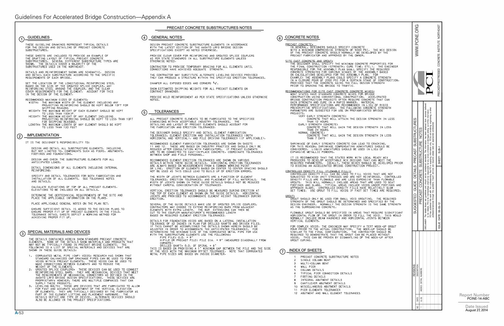
A-53
Report Number PCINE-14-ABC
Date Issued August 27, 2014
Guidelines For Accelerated Bridge Construction—Appendix A
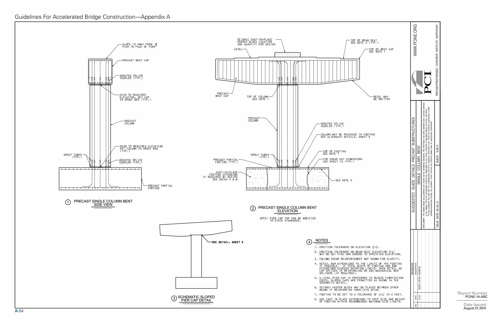
A-54
Report Number PCINE-14-ABC
Date Issued August 27, 2014
Guidelines For Accelerated Bridge Construction—Appendix A
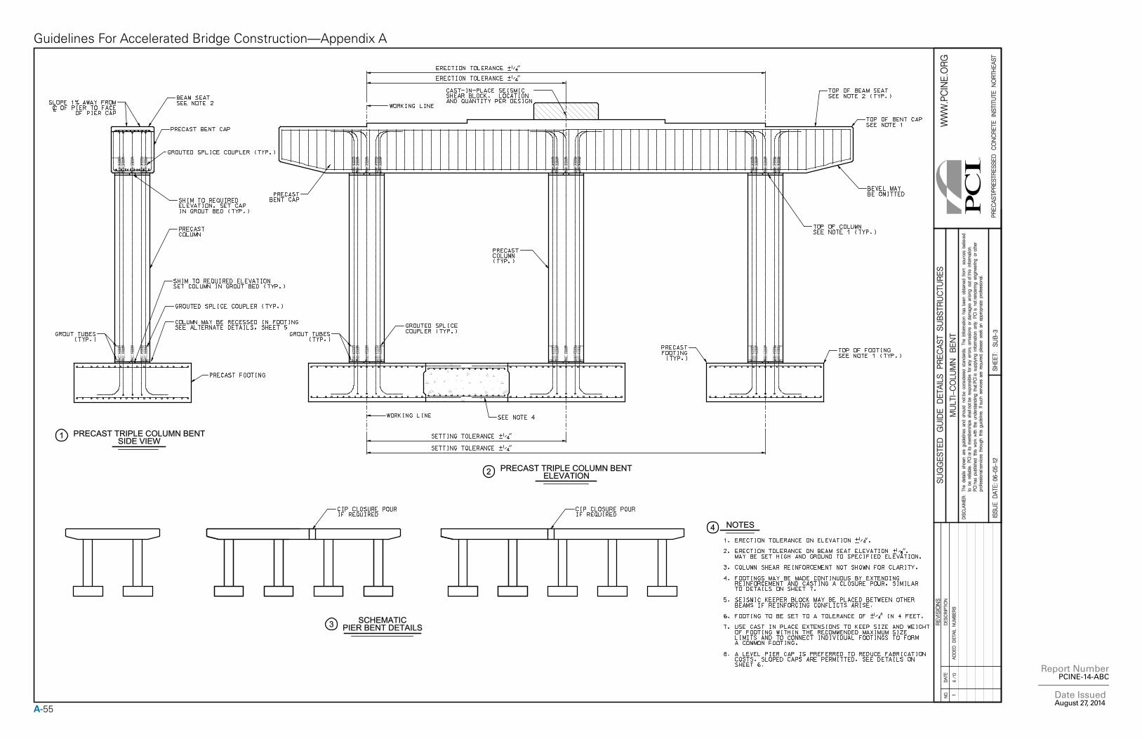
A-55
Report Number PCINE-14-ABC
Date Issued August 27, 2014
Guidelines For Accelerated Bridge Construction—Appendix A
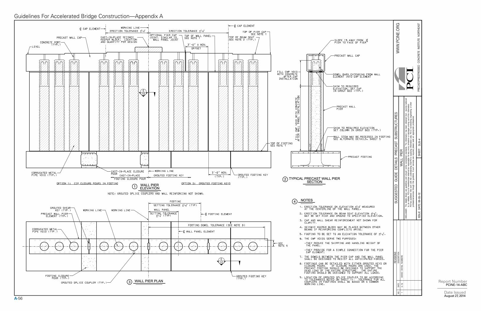
A-56
Report Number PCINE-14-ABC
Date Issued August 27, 2014
Guidelines For Accelerated Bridge Construction—Appendix A
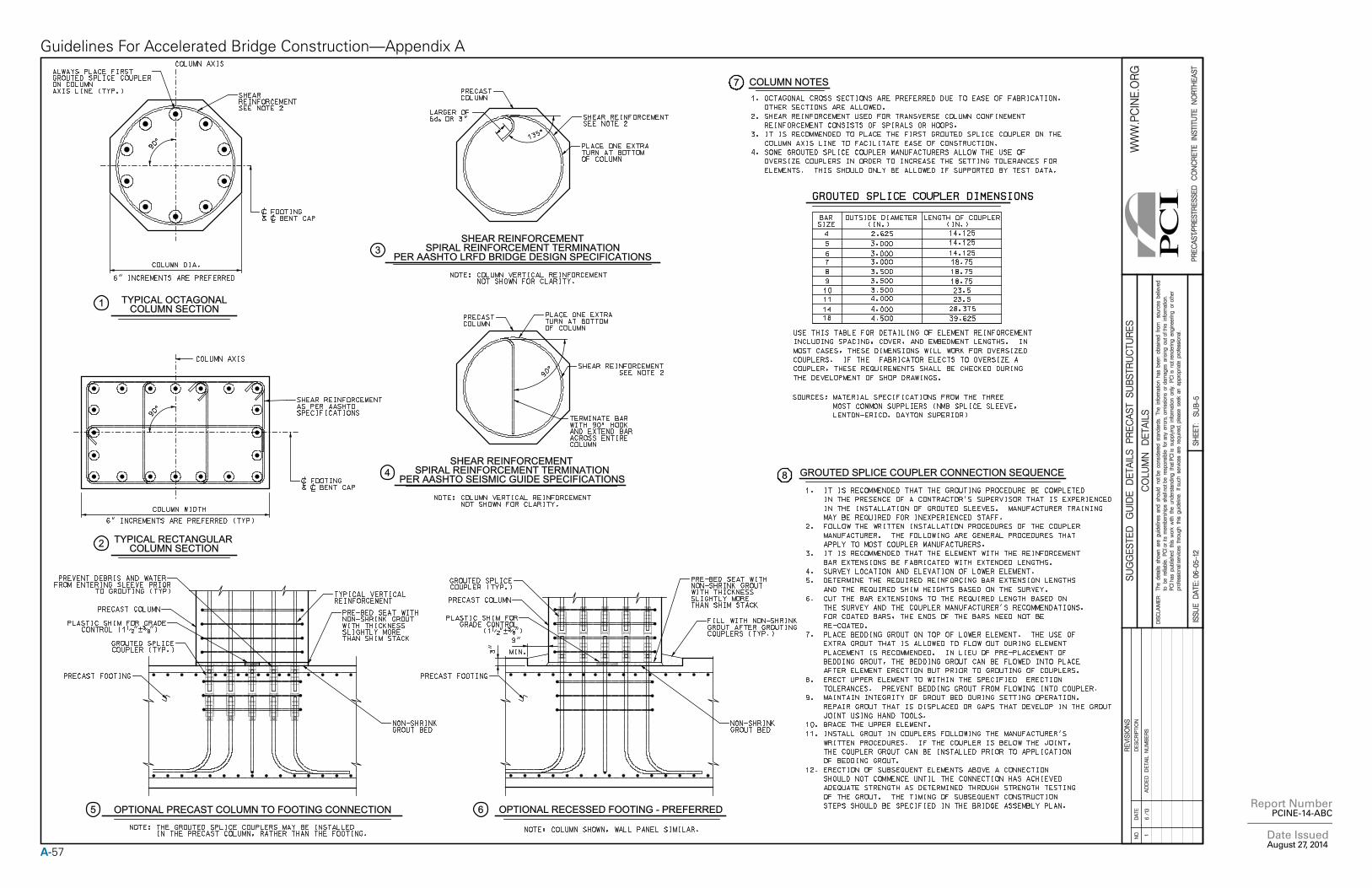
A-57
Report Number PCINE-14-ABC
Date Issued August 27, 2014
Guidelines For Accelerated Bridge Construction—Appendix A
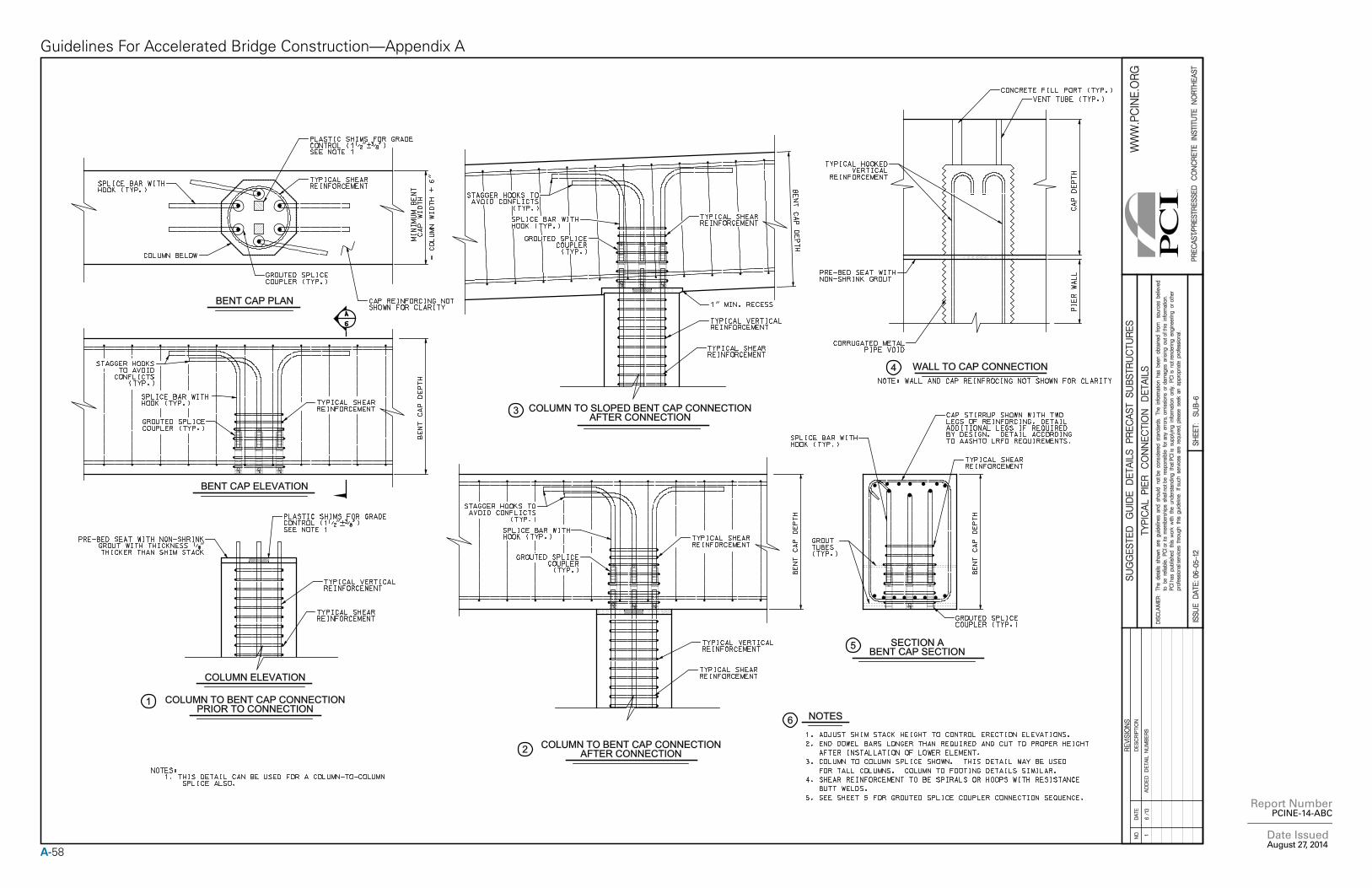
A-58
Report Number PCINE-14-ABC
Date Issued August 27, 2014
Guidelines For Accelerated Bridge Construction—Appendix A
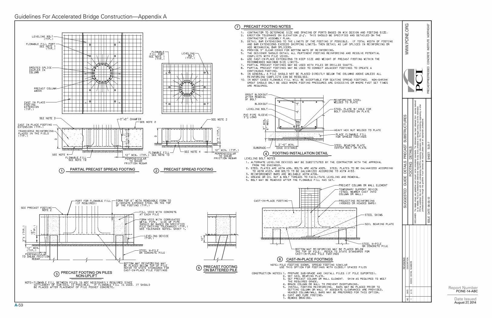
A-59
Report Number PCINE-14-ABC
Date Issued August 27, 2014
Guidelines For Accelerated Bridge Construction—Appendix A
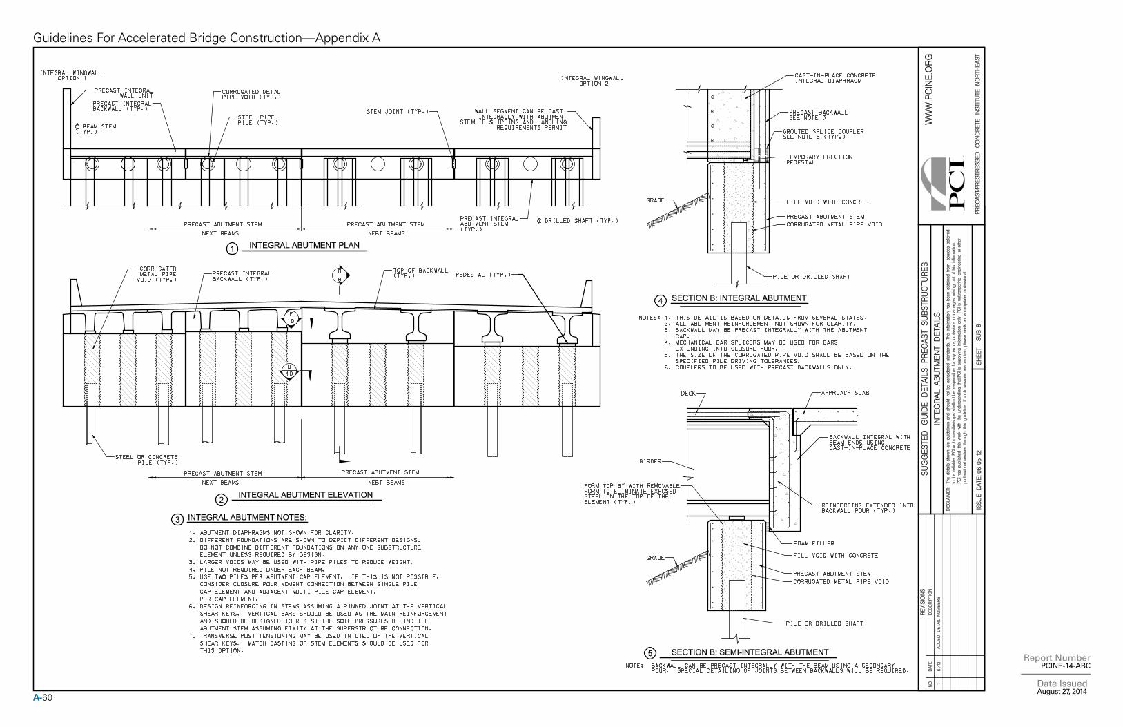
A-60
Report Number PCINE-14-ABC
Date Issued August 27, 2014
Guidelines For Accelerated Bridge Construction—Appendix A
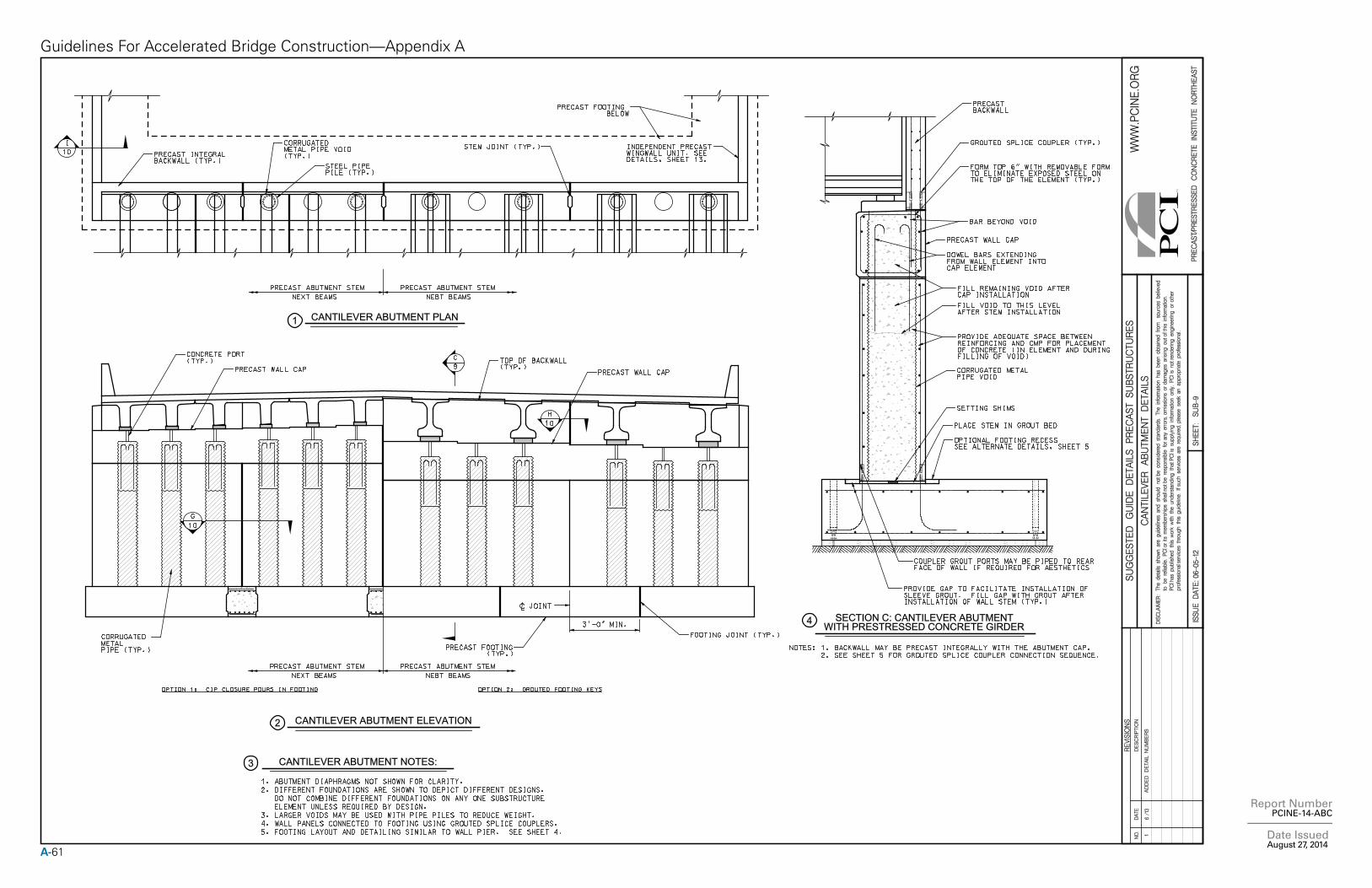
A-61
Report Number PCINE-14-ABC
Date Issued August 27, 2014
Guidelines For Accelerated Bridge Construction—Appendix A
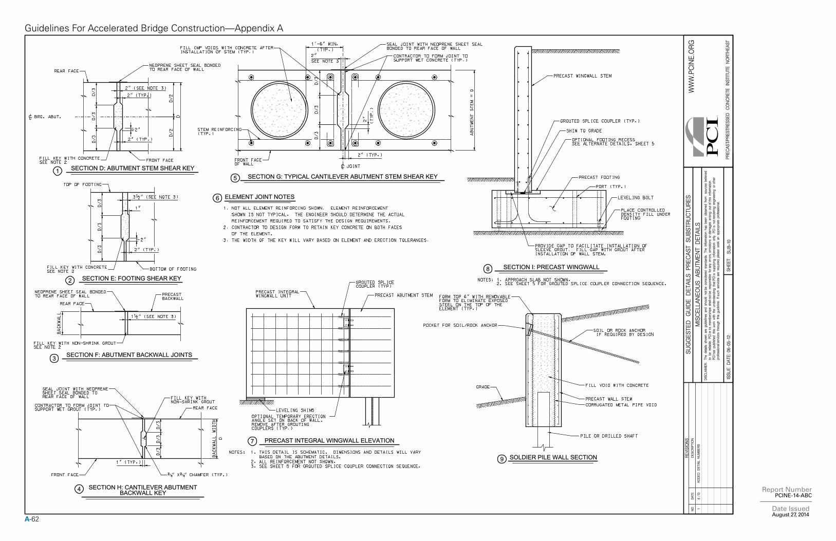
A-62
Report Number PCINE-14-ABC
Date Issued August 27, 2014
Guidelines For Accelerated Bridge Construction—Appendix A
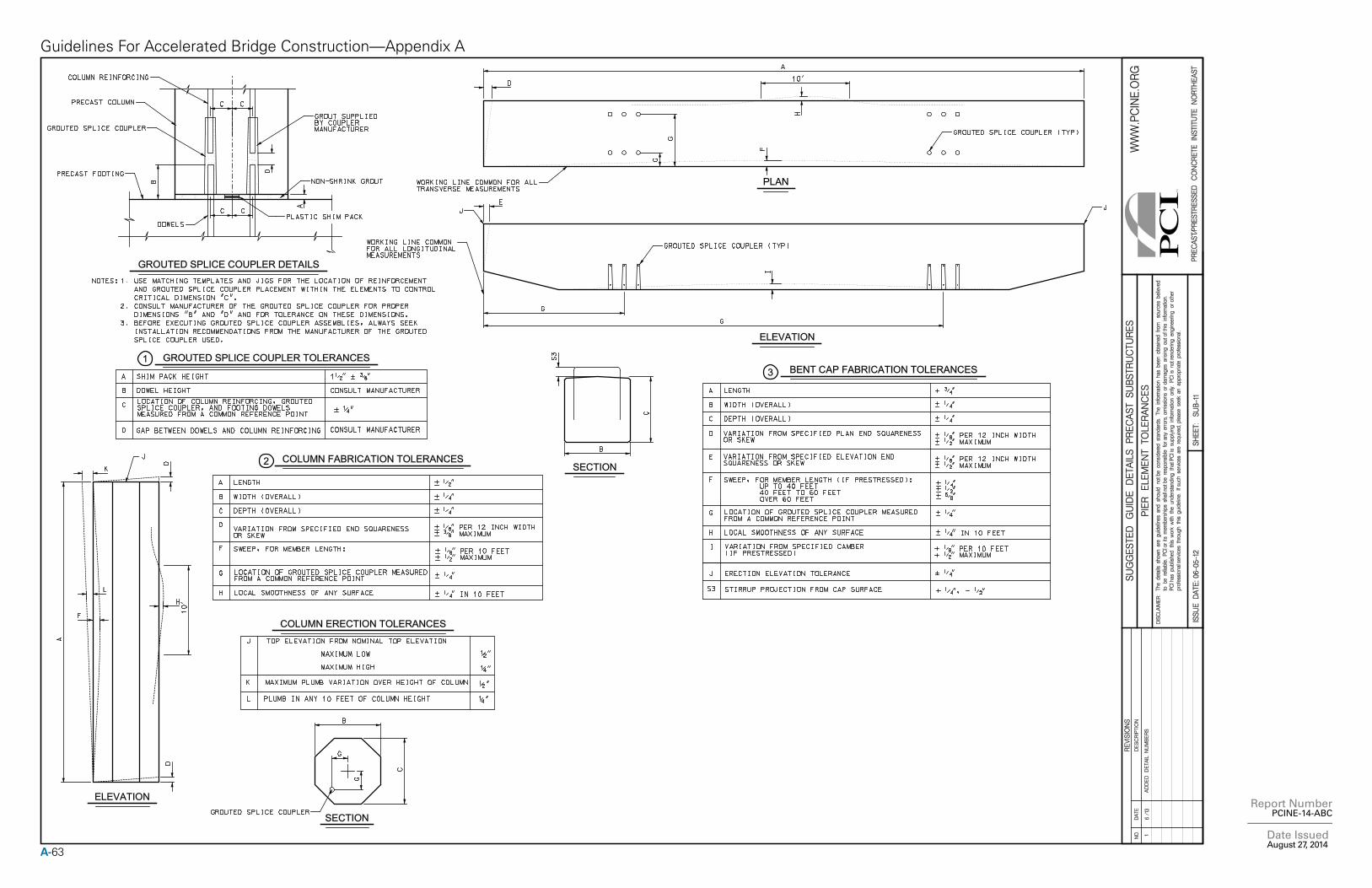
A-63
Report Number PCINE-14-ABC
Date Issued August 27, 2014
Guidelines For Accelerated Bridge Construction—Appendix A
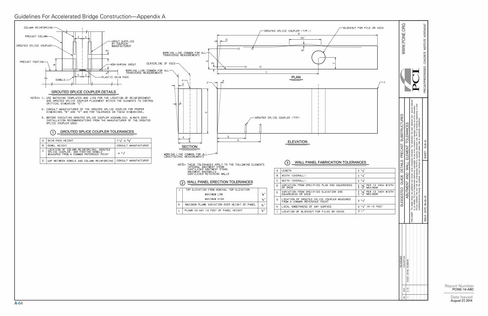
A-64
Report Number PCINE-14-ABC
Date Issued August 27, 2014
Guidelines For Accelerated Bridge Construction—Appendix A
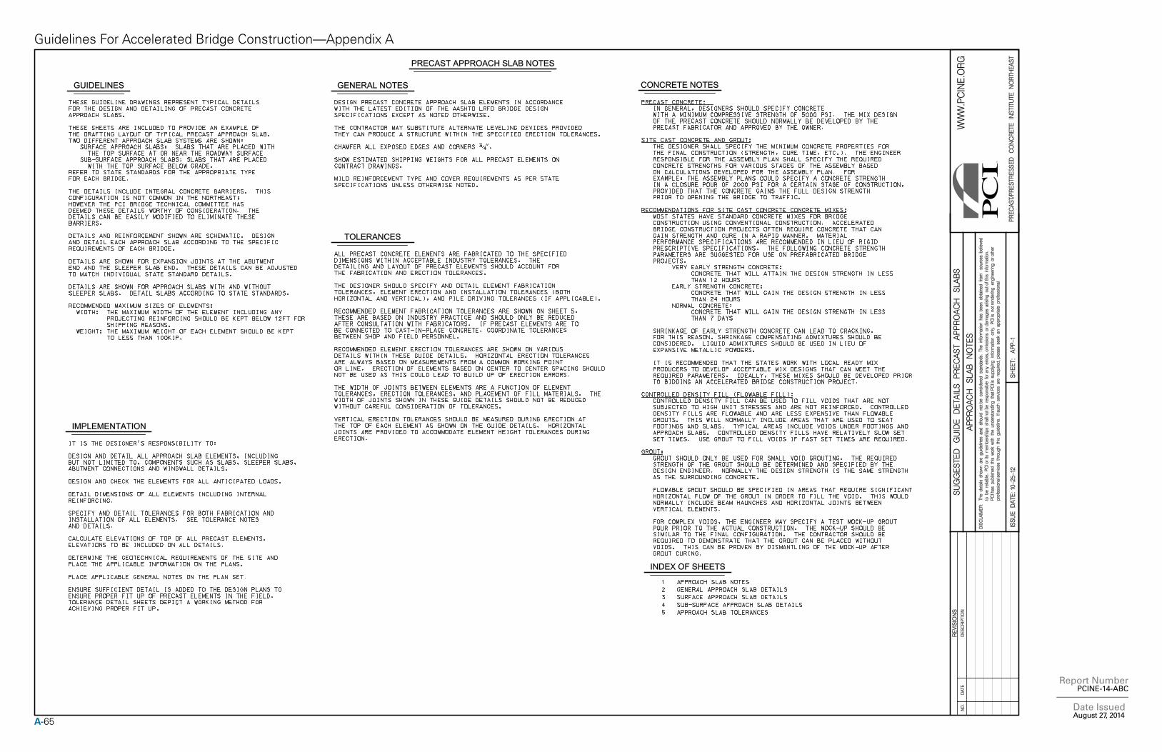
A-65
Report Number PCINE-14-ABC
Date Issued August 27, 2014
Guidelines For Accelerated Bridge Construction—Appendix A
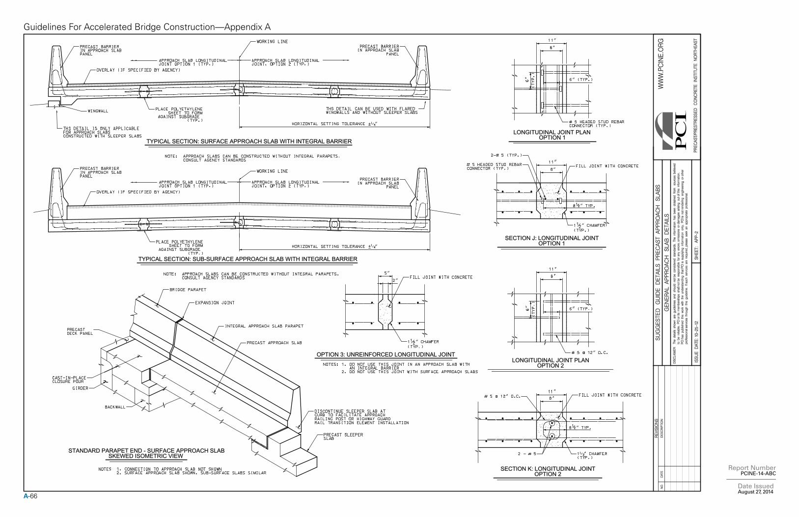
A-66
Report Number PCINE-14-ABC
Date Issued August 27, 2014
Guidelines For Accelerated Bridge Construction—Appendix A
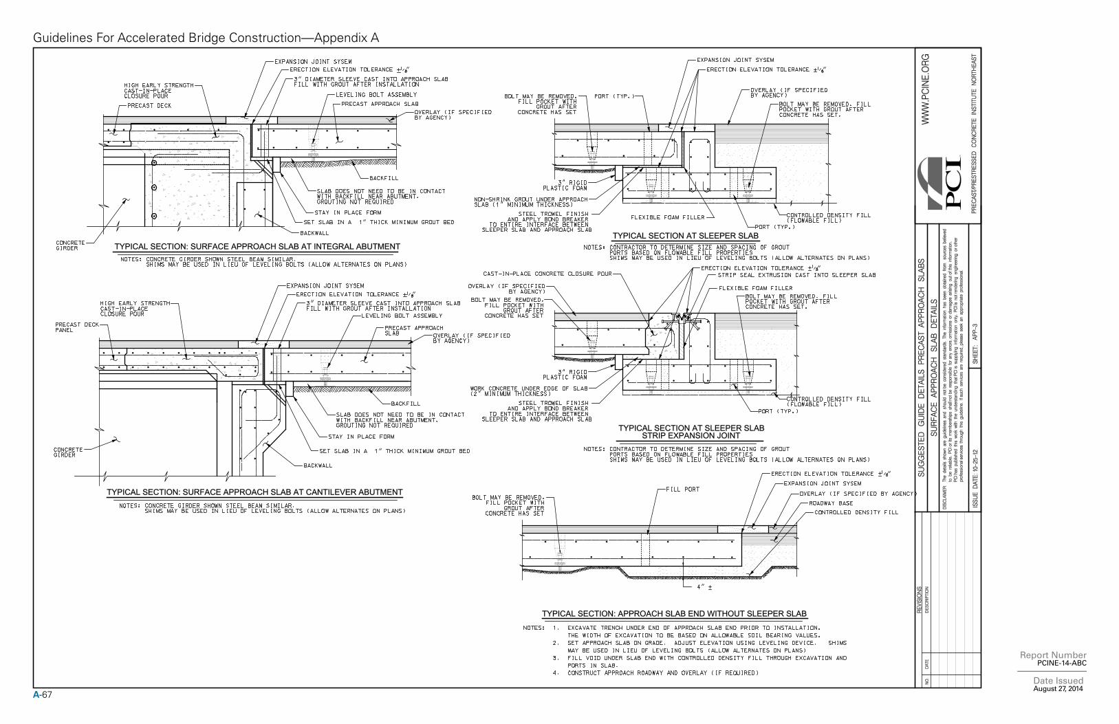
A-67
Report Number PCINE-14-ABC
Date Issued August 27, 2014
Guidelines For Accelerated Bridge Construction—Appendix A
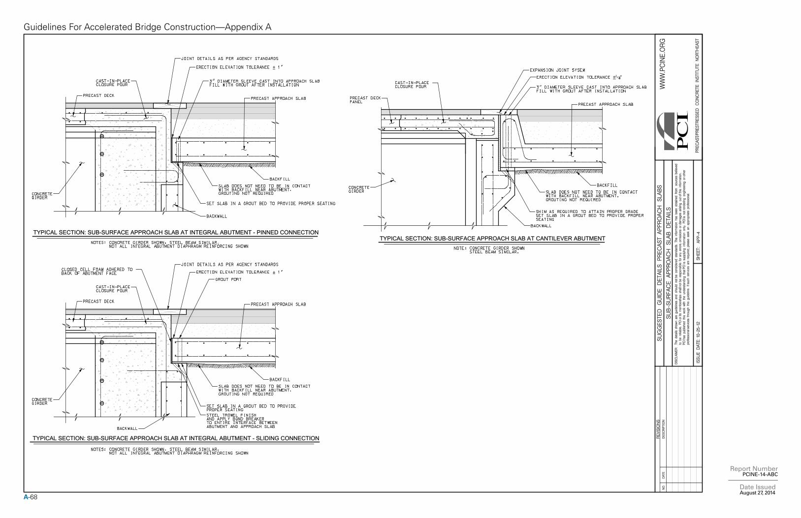
A-68
Report Number PCINE-14-ABC
Date Issued August 27, 2014
Guidelines For Accelerated Bridge Construction—Appendix A
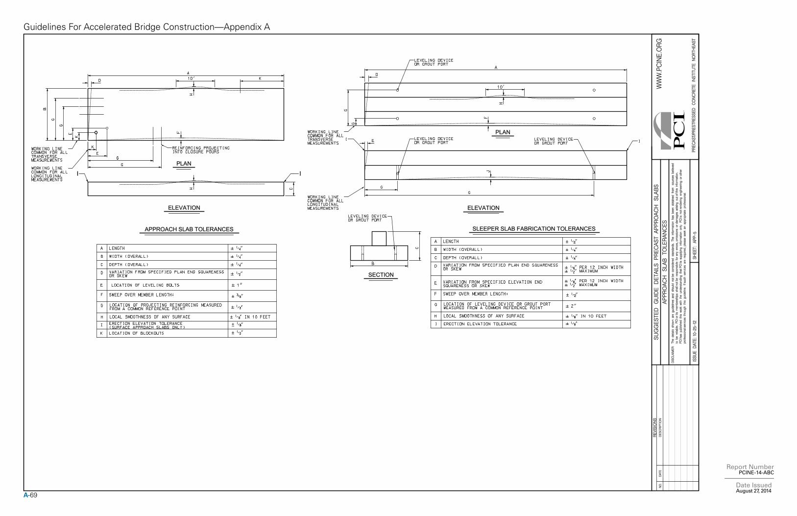
A-69
Report Number PCINE-14-ABC
Date Issued August 27, 2014
Guidelines For Accelerated Bridge Construction—Appendix A


NORTHEAST
A Chapter of thePrecast/Prestressed Concrete Institute
116 Radcliffe Road • Belmont, MA 02478 Phone: 888.700.5670 • Fax: 617.489.5810 © 2014 PCINE