Embed Size (px)
Citation preview

https://support.industry.siemens.com/cs/ww/en/view/109478811
Background and System Description 09/2015
Guide for Migrating SIMATIC S7-300/S7-400 to SIMATIC S7-1500 and TIA Portal Boundary Conditions and Procedure for Migrating Hardware and Software

Warranty and Liability
Migrating S7-300/S7-400 to S7-1500 Entry ID: 109478811, V1.0, 09/2015 2
S
iem
en
s A
G 2
01
5 A
ll ri
gh
ts r
ese
rve
d
Warranty and Liability
Note The Application Examples are not binding and do not claim to be complete with regard to configuration, equipment or any contingencies. The Application Examples do not represent customer-specific solutions. They are only intended to provide support for typical applications. You are responsible for the correct operation of the described products. These Application Examples do not relieve you of the responsibility of safely and professionally using, installing, operating and servicing equipment. When using these Application Examples, you recognize that we cannot be made liable for any damage/claims beyond the liability clause described. We reserve the right to make changes to these Application Examples at any time and without prior notice. If there are any deviations between the recommendations provided in this Application Example and other Siemens publications – e.g. catalogs – the contents of the other documents have priority.
We do not accept any liability for the information contained in this document.
Any claims against us – based on whatever legal reason – resulting from the use of the examples, information, programs, engineering and performance data etc., described in this application example will be excluded. Such an exclusion will not apply in the case of mandatory liability, e.g. under the German Product Liability Act (“Produkthaftungsgesetz”), in case of intent, gross negligence, or injury of life, body or health, guarantee for the quality of a product, fraudulent concealment of a deficiency or breach of a condition which goes to the root of the contract (“wesentliche Vertragspflichten”). The compensation for damages due to a breach of a fundamental contractual obligation is, however, limited to the foreseeable damage, typical for the type of contract, except in the event of intent or gross negligence or injury to life, body or health. The above provisions do not imply a change of the burden of proof to your detriment.
Any form of duplication or distribution of these Application Examples or excerpts hereof is prohibited without the expressed consent of Siemens Industry Sector.
Security informa-
tion
Siemens provides products and solutions with industrial security functions that support the secure operation of plants, solutions, machines, equipment and/or networks. They are important components in a holistic industrial security concept. With this in mind, Siemens’ products and solutions undergo continuous development. Siemens recommends strongly that you regularly check for product updates.
For the secure operation of Siemens products and solutions, it is necessary to take suitable preventive action (e.g. cell protection concept) and integrate each component into a holistic, state-of-the-art industrial security concept. Third-party products that may be in use should also be considered. For more information about industrial security, visit http://www.siemens.com/industrialsecurity.
To stay informed about product updates as they occur, sign up for a product-specific newsletter. For more information, visit https://support.industry.siemens.com.

Table of Contents
Migrating S7-300/S7-400 to S7-1500 Entry ID: 109478811, V1.0, 09/2015 3
S
iem
en
s A
G 2
01
5 A
ll ri
gh
ts r
ese
rve
d
Table of Contents Warranty and Liability ................................................................................................. 2
1 Introduction ........................................................................................................ 5
1.1 Purpose of this document..................................................................... 5
2 Planning a Plant Migration ............................................................................... 6
2.1 General procedure ............................................................................... 6 2.2 Partial or complete migration................................................................ 7 2.3 Planning the migration phases ............................................................. 9 2.4 Advantages of modernization ............................................................. 10
3 SIMATIC S7-300/S7-400 and SIMATIC S7-1500 System Architecture ........ 11
3.1 SIMATIC S7-300/S7-400.................................................................... 11 3.1.1 Information on the SIMATIC S7-300 automation system ................... 12 3.1.2 Information on the SIMATIC S7-400 automation system ................... 13 3.2 SIMATIC S7-1500 .............................................................................. 14 3.2.1 CPU .................................................................................................... 14 3.2.2 Information on the SIMATIC S7-1500 automation system ................. 14
4 Hardware Migration ......................................................................................... 16
4.1 General information on migrating the hardware ................................. 16 4.1.1 Reasons for a migration ..................................................................... 16 4.1.2 Support, aids ...................................................................................... 16 4.2 Selecting the CPU .............................................................................. 17 4.3 Centralized and distributed I/O ........................................................... 18 4.3.1 Centralized I/O ................................................................................... 18 4.3.2 Expansion racks in S7-300/S7-400 .................................................... 18 4.3.3 Distributed I/O .................................................................................... 19 4.4 Communication and networks ............................................................ 21 4.5 Operator control and monitoring ........................................................ 22 4.5.1 HMI hardware ..................................................................................... 22 4.5.2 HMI software ...................................................................................... 22
5 Software Conversion ....................................................................................... 23
5.1 General information on software conversion...................................... 23 5.1.1 Programming languages .................................................................... 24 5.1.2 Option packages and expansions ...................................................... 25 5.1.3 Versions of the TIA Portal .................................................................. 26 5.1.4 Requirements Licensing ..................................................................... 26 5.1.5 Programming environment ................................................................. 27 5.2 Migrating the project ........................................................................... 28 5.2.1 Preparatory steps ............................................................................... 28 5.2.2 Migration from STEP 7 V5.x to STEP 7 (TIA Portal) .......................... 31 5.2.3 Migrating projects with safety program .............................................. 35 5.2.4 Continuing steps - Migrating the CPU S7-300/S7-400 to
S7-1500 .............................................................................................. 37 5.2.5 Optimizing the TIA Portal project ....................................................... 38 5.3 Program structure and standard functions ......................................... 43 5.3.1 Organization blocks (OB) ................................................................... 43 5.3.2 Function blocks and functions, data blocks........................................ 45 5.3.3 Differences between STEP 7 V5.5 and STEP 7 TIA Portal ............... 46 5.3.4 Differences in the hardware of S7-300/S7-400 and S7-1500 ............ 54 5.4 Programming sequential controls – GRAPH in STEP 7 V5.x and
TIA Portal ........................................................................................... 55
6 The most important Recommendations ........................................................ 56

Table of Contents
Migrating S7-300/S7-400 to S7-1500 Entry ID: 109478811, V1.0, 09/2015 4
S
iem
en
s A
G 2
01
5 A
ll ri
gh
ts r
ese
rve
d
6.1 Contacts in the region ........................................................................ 56 6.2 Services offered by Siemens ............................................................. 56 6.3 Solution Partner .................................................................................. 56 6.4 References and online documents ..................................................... 57 6.4.1 Important information ......................................................................... 57
7 Appendix .......................................................................................................... 58
7.1 SIMATIC S7-300/S7-400, S7-1500 components and HMI in comparison ......................................................................................... 58
7.1.1 CPU modules ..................................................................................... 59 7.1.2 Comparison of software / hardware properties .................................. 61 7.1.3 Digital modules S7-300 ...................................................................... 65 7.1.4 Digital modules S7-400 ...................................................................... 67 7.1.5 Analog modules S7-300 ..................................................................... 68 7.1.6 Analog modules S7-400 ..................................................................... 69 7.1.7 Communication modules S7-300 ....................................................... 70 7.1.8 Function modules S7-300 .................................................................. 71 7.1.9 Function modules S7-400 .................................................................. 72 7.1.10 Operator panels .................................................................................. 73
8 History............................................................................................................... 74

1 Introduction
Migrating S7-300/S7-400 to S7-1500 Entry ID: 109478811, V1.0, 09/2015 5
S
iem
en
s A
G 2
01
5 A
ll ri
gh
ts r
ese
rve
d
1 Introduction The new SIMATIC S7-1500 controller generation has an up-to-date system architecture and, together with TIA Portal, offers new and efficient programming and configuration options.
This document contains recommendations and notes on a generation change for users who are currently using SIMATIC S7-300/S7-400 automation systems and plan to migrate to the new SIMATIC controller generation S7-1500.
1.1 Purpose of this document
The objective of this document is to support plant migration to a modern controller generation and cover the most important questions that may arise in this context.
This document does not claim to cover all conceivable plant configurations and SIMATIC S7-300/S7-400 components used.
Migration means changing software and hardware and transferring data from one environment to another largely using existing technological infrastructure. Migration goes beyond a simple update or upgrade and refers to a fundamental change of the system.
Note This document is not valid with SIMATIC S7-400 in combination with PCS 7.

2 Planning a Plant Migration
Migrating S7-300/S7-400 to S7-1500 Entry ID: 109478811, V1.0, 09/2015 6
S
iem
en
s A
G 2
01
5 A
ll ri
gh
ts r
ese
rve
d
2 Planning a Plant Migration
2.1 General procedure
In the run-up to plant migration, there is considerable need for clarification. Therefore, it is all the more important to develop a detailed comprehensive concept for planning and implementing the pending migration.
Each plant has different requirements for the migration process. Depending on the complexity of the plant control system, acceptable machine downtimes and production flexibility, the required preparation, procedure and depth of migration may differ.
It is always necessary to think out and plan migration of the entire plant, even if only a partial migration is considered. The question is not “how do I migrate a controller?” but “what should the plant look like at the end of migration and which migration steps are necessary?”.
Considerations and issues to be dealt with before migration:
Which plant parts should be migrated?
– Even a partial migration requires that the entire plant be considered.
Which components are affected?
– Stand-alone solutions or complex plant configuration
– Communication with third-party systems
– Existing special hardware or software components
Which considerations are important for planning the migration time?
– Schedule non-production times
– 24/7 production
– Produce in advance to buffer downtimes
– Temporarily shift production
Fall-back strategies
– Allow quick migration back to previous hardware/software platform
– Sufficient time buffers
– Comprehensive tests up to the "point of no return"
– New communication cabling even despite potential continued use of existing communication connections
Minimizing risk
– Accurately capture the actual plant
– Detailed planning of each individual trade
– Identify and consider dependencies
– Gradual migration
– Separate migration of centralized / distributed
– Retain the cabling
– Partial acceptances
– Preliminary tests in the laboratory
– Test connections to the control systems
Plant operation after migration

2 Planning a Plant Migration
Migrating S7-300/S7-400 to S7-1500 Entry ID: 109478811, V1.0, 09/2015 7
S
iem
en
s A
G 2
01
5 A
ll ri
gh
ts r
ese
rve
d
– Timely training of operating and maintenance staff
– Implement changed/improved processes
– Different cycle times of the plant
– Schedule spare parts planning for future plant expansion and improvements
2.2 Partial or complete migration
What is decisive for the migration scope?
Complexity of the control solution
– Single controller or multiple networked controllers
– Connection to control system/third-party systems
– Controllers, operator control and monitoring equipment used
– Special functions such as positioning, PID, counter modules
– Which bus systems, centralized/distributed I/Os
– Communication modules/protocols
Know-how of the existing plant
– Core functions and communication
– Processes
– Connection of control systems
– Original suppliers
– Existing documentation and project software
Components that cannot be replaced (directly)
– H systems
– Special drives
– Control systems, special SCADA systems
Allowed production downtime
– 24/7 production
– Holiday shutdown
– Produce in advance
– Shift (parts of) production
Available budget and time frame
Applicable standards and regulations
Production flexibility
Modernization and improvement
– Quicker cycle times, higher production quantities
– Improved product quality
– Lower energy and production costs
– Higher availability, faster corrective maintenance times
Upgrades and expansions planned for the future

2 Planning a Plant Migration
Migrating S7-300/S7-400 to S7-1500 Entry ID: 109478811, V1.0, 09/2015 8
S
iem
en
s A
G 2
01
5 A
ll ri
gh
ts r
ese
rve
d
In the end, all these influencing factors determine the decision on the type of migration that can be implemented:
– Complete migration
– Complete migration in phases
– Partial migration
– New version
Table 2-1
Type Purpose Advantages Disadvantages
Partial migration Replacement of devices due to end of product life cycle
Increased productivity with new devices
Investment protection, low effort
Two systems, if necessary
System expansion Expansion of an existing plant
Protection of investment Two systems
Complete migration
Exchanging the hardware, migration of software
Innovative products, advantages of the new system are used completely
High workload

2 Planning a Plant Migration
Migrating S7-300/S7-400 to S7-1500 Entry ID: 109478811, V1.0, 09/2015 9
S
iem
en
s A
G 2
01
5 A
ll ri
gh
ts r
ese
rve
d
2.3 Planning the migration phases
The transition to new technology requires careful planning to avoid problems and ensure maximum use of new functions and capabilities. For these reasons, it is important to the take time to plan the objectives and required steps before the start of the migration process.
The following table provides a brief description of how to implement the required phases.
Phase Designation Description
1 Plant audit Identifying the status quo of the plant/machine
Identification and documentation of all control and plant components.
2 Analysis Analyzing the installed base
Analysis of all components, incl. third-party systems, communication types and their dependencies in the system. Definition of contributory trades.
3 Strategy Developing options
Consideration of all options, followed by the identification of potential obstacles.
4 Review Defining solutions, products, standards
Decision on the solutions, products and standards to be used.
5 Specification Checking the specifications
Detailed analysis of all specifications relating to the basic and additional functions.
6 Planning Defining the implementation plan
Technical and schedule planning of the individual migration phases.
7 Migration Implementing the migration project
Active project support with the aid of the entire Service and Support portfolio.
8 Service Integration and planning of maintenance and service
Early planning of the service concept, spare parts procurement, operating concepts and training
2 Planning a Plant Migration
Migrating S7-300/S7-400 to S7-1500 Entry ID: 109478811, V1.0, 09/2015 10
S
iem
en
s A
G 2
01
5 A
ll ri
gh
ts r
ese
rve
d
2.4 Advantages of modernization
The S7-1500 system supplements the previous S7-300/S7-400 systems. The S7-300, S7-400 and S7-1500 systems are marketed parallel within the next years. Phasing out S7-300/S7-400 is not scheduled before 2020. Thereafter, the components of both systems are available for another 10 years.
Note For more information, please refer to the delivery release of the S7-1500 controller.
https://support.industry.siemens.com/cs/ww/en/view/67856446
Meanwhile, mechanisms and technologies have changed. A modern SIMATIC automation system such as the S7-1500 can offer you the following technical and financial benefits:
Increased productivity
Reduced total production costs by means of integrated system diagnostics and a resulting increased plant availability, for example.
Increased utilization of machines
Compliance with new regulations, for example: Security, protection against contemporary hazards
Improved product quality and process control
Greater flexibility in production and production planning
Support of future integration and expansion of your plants
Support of state-of-the-art manufacturing technology
Access to a pool of employees familiar with state-of-the-art automation technology and capable of maintaining modernized plants
The risk for old plants increases continuously due to the difficult spare parts supply situation

3 SIMATIC S7-300/S7-400 and SIMATIC S7-1500 System Architecture
Migrating S7-300/S7-400 to S7-1500 Entry ID: 109478811, V1.0, 09/2015 11
S
iem
en
s A
G 2
01
5 A
ll ri
gh
ts r
ese
rve
d
3 SIMATIC S7-300/S7-400 and SIMATIC S7-1500 System Architecture
3.1 SIMATIC S7-300/S7-400
Figure 3-1 Automation systems SIMATIC S7-300/S7-400 and S7-1500
System Automation
Factory Automation
Lower performance-range
S7-400
S7-300
Advanced Controller
Basic Controller
S7-1200
S7-1500
S7-200

3 SIMATIC S7-300/S7-400 and SIMATIC S7-1500 System Architecture
Migrating S7-300/S7-400 to S7-1500 Entry ID: 109478811, V1.0, 09/2015 12
S
iem
en
s A
G 2
01
5 A
ll ri
gh
ts r
ese
rve
d
3.1.1 Information on the SIMATIC S7-300 automation system
The SIMATIC S7-300 automation system is a programmable logic controller for factory automation/machine manufacturing in the field of OEM. S7-300 is a system with modular design and consists of the individual components:
Power supply modules
Central processing units
Input and output modules
Signal preprocessing modules
Communications processors
Function modules
These SIMATIC S7 components are mounted to an aluminum rack. This rack is used to mechanically fasten all modules. To enable communication with the following modules, the bus connectors are used on the backplane.
Expansion options
If necessary, the connection capacity of the central rack can be increased by expansion devices (IM 360 S, IM 361 R, 365 S-R). Appropriate interface modules connect the central controller to the expansion racks.
Memory concept
The S7-300 is programmed using the STEP 7 Siemens programming software. The control program can be transferred to the central processing unit (CPU) via a programming unit.
The user program is stored in the load memory of the CPU. Since the CPU does not have an internal load memory, a memory card (MMC) is used here. Since the program is not stored volatile on the MMC, a buffer battery is not necessary. The Micro Memory Card is necessary for operating the CPU. The size of the internal program memory varies depending on the CPU type.
Note The 1st generation of S7-300 CPUs had worked with a memory card. It was
necessary to provide a buffer battery for the CPU to maintain the program in the event of a power failure.
Note Information on the S7-300 automation system is described: https://support.industry.siemens.com/cs/ww/en/view/8859629

3 SIMATIC S7-300/S7-400 and SIMATIC S7-1500 System Architecture
Migrating S7-300/S7-400 to S7-1500 Entry ID: 109478811, V1.0, 09/2015 13
S
iem
en
s A
G 2
01
5 A
ll ri
gh
ts r
ese
rve
d
3.1.2 Information on the SIMATIC S7-400 automation system
Note This document is not valid with SIMATIC S7-400 in combination with PCS 7.
The SIMATIC S7-400 automation system is a programmable logic controller for plant automation. In the field of process automation, redundancy concepts are often used for increased plant availability. The CPUs S7-400H and recently S7-410H are used here. This particular new controller type will also be further developed in the future.
Its modular design allows you to variably equip a central controller with modules and adapt it to the respective automation task.
The possible configuration of the S7-400 includes the following different module types:
Power supply modules
Central processing units
Input and output modules
IM modules
Communications processors
Function modules
These SIMATIC S7 components are mounted to a module rack. It is also used for mechanically fixing all modules and contains the bus PCB that electrically and logically interconnects the modules.
Expansion options
If necessary, the connection capacity of the central rack can be increased by expansion devices (IM 460 S, IM 461 R). Appropriate interface modules connect the central controller to the expansion racks.
Memory concept
Programming the S7-400 is performed in STEP 7. The user program can be transferred to the central processing unit (CPU) via a programming unit and is stored in the load memory of the CPU. The integrated main memory is used here for processing. The memory capacity depends on the CPU type used. Memory cards (RAM type) can be used here for expanding the load memory. In this case, the data is only stored volatile, i.e. if a buffer battery is not used in the power supply, the data will be lost after switching off. As soon as the memory card (RAM type) is pulled from the CPU, data will also be lost. If a memory card (flash type) is used, data (the entire user program or service data) cannot be stored volatile.
Note Information on the automation device S7-400 is available in the SIMATIC S7-400 manual. https://support.industry.siemens.com/cs/ww/en/view/44444467

3 SIMATIC S7-300/S7-400 and SIMATIC S7-1500 System Architecture
Migrating S7-300/S7-400 to S7-1500 Entry ID: 109478811, V1.0, 09/2015 14
S
iem
en
s A
G 2
01
5 A
ll ri
gh
ts r
ese
rve
d
3.2 SIMATIC S7-1500
3.2.1 CPU
Compared to the SIMATIC S7-300/S7-400 programmable controllers, the available CPU types of the new controller generation S7-1500 show considerable differences and functions. Features and functions of the available CPU types of the S7-1500.
Communication via Ethernet
Communication via PROFIBUS/PROFINET
HMI communication
Integrated web server
Integrated technology
Integrated system diagnostic
Integrated industrial security functions
Safety mode (all S7-1500 CPUs are also available as an F-version)
3.2.2 Information on the SIMATIC S7-1500 automation system
Together with the Totally Integrated Automation Portal (TIA Portal), SIMATIC S7-1500 offers you numerous new options to further increase the productivity of your machines and make the engineering process more efficient.
Thanks to the integration of numerous new performance features, the S7-1500 automation system provides the user with excellent operating capabilities and maximum performance.
The new performance features are:
Increased system performance
Integrated motion control functionality
PROFINET IO IRT
Integrated display for local operator control and diagnostics
STEP 7 language innovations while retaining proven functions
Field of application
The S7-1500 automation system provides the flexibility and performance required for the broad range of control applications in machinery and plant engineering.
The S7-1500 complies with IP20 degree of protection and is intended for installation in a control cabinet.
Design and function
The S7-1500 automation system is mounted onto a DIN rail and can centrally consist of up to 32 modules. The modules are interconnected via multi-pin and shielded U connectors.
The scalable design allows you to tailor your controller to the local requirements.
The system power supply is a power supply module with diagnostics capability that is connected to the backplane bus via a U connector.
The CPU executes the user program and the integrated system power supply supplies the electronics of the modules used via the backplane bus.

3 SIMATIC S7-300/S7-400 and SIMATIC S7-1500 System Architecture
Migrating S7-300/S7-400 to S7-1500 Entry ID: 109478811, V1.0, 09/2015 15
S
iem
en
s A
G 2
01
5 A
ll ri
gh
ts r
ese
rve
d
The I/O modules form the interface between the controller and the process.
Figure 3-2 shows a sample configuration of an S7-1500 automation system.
Figure 3-2 SIMATIC S7-1500
1. System power supply module, e.g. PM1507
2. CPU S7-1500, e.g. CPU 1516
3. I/O modules, function modules, communication modules
Memory concept
As the program memory, the S7-1500 automation system uses a SIMATIC Memory Card. The SIMATIC Memory Card is a preformatted memory card that is compatible with the Windows file system. The memory card is available in various sizes and can be used for the following purposes:
Portable storage medium
Program card (external load memory for the CPU)
Firmware update card
Service data cards
For writing on/reading from the SIMATIC memory card, a standard SD card reader installed in the SIMATIC field PG and most PCs is sufficient. The SIMATIC Memory Card is mandatory for operating the CPU.
Note The SIMATIC S7-1500 system manual provides information on the S7-1500 automation system.
https://support.industry.siemens.com/cs/ww/en/view/86140384
1 2 3

4 Hardware Migration
Migrating S7-300/S7-400 to S7-1500 Entry ID: 109478811, V1.0, 09/2015 16
S
iem
en
s A
G 2
01
5 A
ll ri
gh
ts r
ese
rve
d
4 Hardware Migration
4.1 General information on migrating the hardware
4.1.1 Reasons for a migration
Modernization
Protection of investment
Migration to current engineering (more efficient working, increased flexibility)
Basis for future modifications
Shorter product introduction times
Reduced operational costs
4.1.2 Support, aids
Siemens and its certified partners facilitate migration by providing:
Check tool
- Readiness Check Tool (https://support.industry.siemens.com/cs/ww/en/view/60162195)
Conversion tools
– Already integrated in STEP 7 (TIA Portal)
– Migration Tool (enables migration: without installed TIA Portal)
Guides for step-by-step implementation, including the associated technical documentation
Training for the migration from SIMATIC S7-300/S7-400 to S7 1500
– from STEP 7 V5.x to STEP 7 TIA Portal
– Guide for replacing the recommended hardware
Documents in the internet (www.siemens.de/tia-migration) and in the Service Portal (https://support.industry.siemens.com)

4 Hardware Migration
Migrating S7-300/S7-400 to S7-1500 Entry ID: 109478811, V1.0, 09/2015 17
S
iem
en
s A
G 2
01
5 A
ll ri
gh
ts r
ese
rve
d
4.2 Selecting the CPU
Like SIMATIC S7-300/S7-400, SIMATIC S7-1500 also provides a selection of CPUs with different performance levels.
For reference, the Appendix provides an overview table that compares the S7-300/S7-400 CPU to the recommended S7-1500 CPUs. (Chapter 7.1.1 CPU modules)
As - aside from criteria such as processing speed, internal memory, number of interfaces and communication connections, etc. - there are other plant-dependent selection criteria, the tables only provide a rough guide for selecting the CPU.
Examples of other plant-dependent selection criteria:
Does the S7-300/S7-400 CPU still have reserves or is it already operated in the limit range of the automation task (terminal-terminal response time, cycle time, memory requirements, …)?
Should plant parts that belong together logically or logistically and that have previously been separated on the controller side be combined to one shared control area? Keyword: Plant redesign

4 Hardware Migration
Migrating S7-300/S7-400 to S7-1500 Entry ID: 109478811, V1.0, 09/2015 18
S
iem
en
s A
G 2
01
5 A
ll ri
gh
ts r
ese
rve
d
4.3 Centralized and distributed I/O
4.3.1 Centralized I/O
The basic design of the centralized I/O of the SIMATIC S7-300/S7-400 differs only insignificantly from the one of the S7-1500. Both systems share the same design where the CPU and the centralized I/O are connected via an appropriate backplane bus. Module connectors are used to connect the systems to the plant I/O.
4.3.2 Expansion racks in S7-300/S7-400
SIMATIC S7-300/S7-400 provided the option to expand the centralized I/O by more I/O modules with the aid of expansion units (module racks 1-3). The expansion racks are connected to the central unit by means of the respective interface modules IM 36x or IM 46x (module rack 0).
Table 4-1
Central unit interface Expansion unit interface Maximum number of expansion units
IM 360 S IM 361 R 3
IM 365 S-R IM 365 S-R 1
Table 4-2
Central unit interface
Expansion unit interface
Maximum number of expansion units
Power supply
IM 460-0 S IM 461-0 4 Feed in EU
IM 460-1 S IM 461-1 4 Feed in EU
IM 460-3 S IM 461-3 1 Transferred during connection
IM 460-4 S IM 461-4 4 Feed in EU
For S7 1500, these particular interface modules are not necessary, since up to 32 modules can be plugged side by side in the central configuration.
In comparison, the following 2 maximum configurations are listed:
Table 4-3
Smallest maximum configuration Largest maximum configuration
PS+CPU1511/1513+modules with 25mm
870 mm
PS+CPU1517/1518+modules with 35mm 1370mm
If the control cabinet does not provide the necessary width for a central configuration, there is the option of connecting a distributed station in the control cabinet via PROFINET.

4 Hardware Migration
Migrating S7-300/S7-400 to S7-1500 Entry ID: 109478811, V1.0, 09/2015 19
S
iem
en
s A
G 2
01
5 A
ll ri
gh
ts r
ese
rve
d
Note Further information on the S7-400 automation system is available in the manual S7-400, M7-400 Programmable Controllers Module Specifications. https://support.industry.siemens.com/cs/ww/en/view/19539653
4.3.3 Distributed I/O
For S7-300/S7-400 as well as S7-1500, distributed I/Os can be connected via PROFIBUS or PROFINET, for example, ET200SP, ET200MP, ET200AL, ET200pro, ET200eco or ET200iSP. How and which I/O is used depends on some factors (e.g. quantity framework/number of inputs and outputs, environmental conditions). The I/O may be maintained during migration.
Table 4-4 Connections for ET200 I/Os
ET200 Type
PB connection
PN connection
Integrated in TIA Portal
ET200SP Yes yes yes
ET200MP Yes yes yes
ET200S Yes yes yes
ET200M Yes yes yes
ET200pro Yes yes yes
ET200iSP Yes no yes
ET200eco Yes yes yes
ET200AL Yes yes yes
ET200R Yes no yes
ET200L Yes no yes
Table 4-5 Properties of the ET200 I/Os
ET200 Type
Properties
ET200SP Control cabinet, IP20, compact size, fine modular
ET200MP Control cabinet, IP20, multi-channel
ET200S Control cabinet, IP20, small size, fine modular
ET200M Control cabinet, IP20, modular, for hazardous area 2/21
ET200pro Without control cabinet, IP6x, M12 connection, modular,
ET200iSP Hazardous area zone 1, 2, 21, 22,
ET200eco Without control cabinet, IP6x, M12, block I/O
ET200AL Without control cabinet, IP6x, M8 / M12 connection, flexible mounting through front or cross-type screwing, typical for handling and mounting applications
ET200R Digital input/output module for robots
ET200L IP20, block I/O

4 Hardware Migration
Migrating S7-300/S7-400 to S7-1500 Entry ID: 109478811, V1.0, 09/2015 20
S
iem
en
s A
G 2
01
5 A
ll ri
gh
ts r
ese
rve
d
Complete migration of plants with ET 200 stations
It is possible to leave the I/O complete during migration (if it is compatible with the CPU).
If the existing system is based on PROFIBUS, the connections could be exchanged for all stations to migrate to PROFINET. Alternatively, an S7-1500 with PROFIBUS can be employed, or a gateway (IE/PB link) which forwards signals centrally from PROFIBUS to PROFINET.
Aside from the central controller, the complete migration to S7-1500 involves migrating the complete I/O to the new control components. For this purpose, the complete ET 200 I/O portfolio is available to you. For example, ET 200SP, ET 200MP, ET 200AL, etc.
Figure 4-1 Migration of distributed plants
Note Even if the partial migration allows direct connection to the OLD I/O, it is recommended to implement the complete migration to ET 200MP/SP/AL/etc. and the connection via PROFINET. When the basic functionality of the plant has been migrated, this can also be done in a second migration step. For example, advantages result from: Improved system diagnostics, faster bus, state-of-the-art technology and relatively easy migration and connection to the existing I/O.
or OLD System PARTIAL Migration COMPLETE Migration

4 Hardware Migration
Migrating S7-300/S7-400 to S7-1500 Entry ID: 109478811, V1.0, 09/2015 21
S
iem
en
s A
G 2
01
5 A
ll ri
gh
ts r
ese
rve
d
4.4 Communication and networks
In SIMATIC S7-300/S7-400 there are a number of options for communication. These were expanded with S7-1500.
System-internal communication
With external communication partners
Numerous communications protocols
An overview provides you with the compendium “CPU-CPU communication”. https://support.industry.siemens.com/cs/ww/en/view/78028908
Note Communication will be discussed in greater detail in a later version of this guide.

4 Hardware Migration
Migrating S7-300/S7-400 to S7-1500 Entry ID: 109478811, V1.0, 09/2015 22
S
iem
en
s A
G 2
01
5 A
ll ri
gh
ts r
ese
rve
d
4.5 Operator control and monitoring
Various devices for visualization tasks are available in different versions. The panels formerly used in combination with S7-300/S7-400 are discontinued. It is therefore recommended to migrate Operator Panels (OP), Touch Panels (TP), Multi or Mobile Panels (MP) to Basic Panels or Comfort Panels.
4.5.1 HMI hardware
When replacing the hardware, please note the requirements for the visualization unit:
Display size/orientation (format change from 4:3 to 16:9, 4“,7“,9“,12“,15“,19“,22“ and horizontal/vertical)
Installation dimensions/cut
Housing material (possibly special environmental conditions)
Type/number of interfaces (MPI, PROFIBUS, PROFINET, USB)
Data storage/storage options/memory size
Note A detailed guideline for migrating older panels to Comfort Panels is available at: https://support.industry.siemens.com/cs/ww/en/view/49752044
4.5.2 HMI software
Migrating the project which is part of the panel is possible. The project muss here be available for WinCC flexible 2008 SP2/SP3, otherwise, migration is not possible. If an older version of the project is available, you must first upgrade to reach this standard. It is also possible to migrate a ProTool project in WinCC TIA Portal. This requires an intermediate step. Das ProTool project must first be migrated to WinCC flexible 2008. Then an upgrade to WinCC (TIA Portal) can be performed.
Note Further information on the topic of migrating WinCC flexible to WinCC (TIA Portal) is available in the respective guideline:
https://support.industry.siemens.com/cs/en/view/77430539

5 Software Conversion
Migrating S7-300/S7-400 to S7-1500 Entry ID: 109478811, V1.0, 09/2015 23
S
iem
en
s A
G 2
01
5 A
ll ri
gh
ts r
ese
rve
d
5 Software Conversion
5.1 General information on software conversion
Generally, you can migrate ALL of your STEP 7 V5.x programs to STEP 7 (TIA Portal)!
However, depending on the STEP 7 commands used or special blocks, it may be necessary to make adjustments after migration.
This chapter explains the most important differences between the two software platforms. In addition, we introduce you to a number of tools. They are intended to provide the best possible support for migration and any adjustments that may be required.
Nevertheless, there may be reasons which make it advisable to rebuild certain programs or programs parts: Examples of such reasons:
Simpler code
Additional functions
Improved diagnostic capability
Creation of standard functions and libraries capable of meeting future requirements
Migration effort same as or higher than rebuilding
Achievement of higher throughputs due to increase in performance
And many more
Note For a general programming guide for SIMATIC S7-1500, refer to the following entry ID:
https://support.industry.siemens.com/cs/ww/en/view/81318674

5 Software Conversion
Migrating S7-300/S7-400 to S7-1500 Entry ID: 109478811, V1.0, 09/2015 24
S
iem
en
s A
G 2
01
5 A
ll ri
gh
ts r
ese
rve
d
5.1.1 Programming languages
STEP 7 V5.x
In SIMATIC STEP 7 V5.x, the following standard programming languages were available:
Ladder diagram (LAD)
Function block diagram (FBD)
Statement list (STL)
Following languages can additionally be used as option package:
Structured Control Language (SCL)
Continuous Function Chart (CFC)
S7-GRAPH
Hi-GRAPH
Note Please note, that between a mere STEP 7 V5.5 and a PCS7 installation, there may be differences since for PCS7 options are already contained.
STEP 7 (TIA Portal)
In SIMATIC STEP 7 (TIA Portal) the following programming languages are available:
Ladder diagram (LAD)
Function block diagram (FBD)
Statement list (STL) (not for S7-1200)
Structured Control Language (SCL)
S7-GRAPH (not for S7-1200)
Note S7-SCL is a high-level-type programming language. Using S7-SCL, particularly more comprehensive functions can be implemented easily and conveniently. Therefore, we recommend that functions such as data handling, search algorithms, copy functions, comparison functions, etc. be converted to S7-SCL when migrating STEP 7 V5.x to STEP 7 (TIA Portal).
Note For an overview of the statements available to you for S7-1500, please use the following link: https://support.industry.siemens.com/cs/ww/en/view/86630375

5 Software Conversion
Migrating S7-300/S7-400 to S7-1500 Entry ID: 109478811, V1.0, 09/2015 25
S
iem
en
s A
G 2
01
5 A
ll ri
gh
ts r
ese
rve
d
5.1.2 Option packages and expansions
For STEP 7 V5.x there are various expansions or option packages, some of them are listed below.
The TIA Portal already provides a wide basis for engineering, since many expansions which still needed to be installed separately in STEP 7 V5.x are now available already integrated.
Table 5-1
STEP 7 V5.x TIA Portal
WinCC Flexible
WinCC
WinCC in TIA Portal
(various variants)
Distributed Safety STEP 7 Safety
SINAMICS MICROMASTER STARTER Startdrive
Teleservice Integrated
Easy Motion Control For S7-300/S7-400/WinAC existing in TIA Portal,
for S7-1500 the functionality is mapped via integrated TO (technology objects)
Modular PID Standard PID PID Selftuner
For S7-300/S7-400/WinAC existing as PID Professional,
for S7-1500, the base functionality can be mapped via integrated TO (technology objects)
integrated
S7 Technology
Different Sirius engineering software Partly available, for example SIMOCODE ES
Note If options or expansions are used in the installation scope of TIA Portal, these must have the same version as STEP 7.

5 Software Conversion
Migrating S7-300/S7-400 to S7-1500 Entry ID: 109478811, V1.0, 09/2015 26
S
iem
en
s A
G 2
01
5 A
ll ri
gh
ts r
ese
rve
d
5.1.3 Versions of the TIA Portal
When installing TIA Portal, please note the following versions:
Table 5-2
STEP 7 Device
STEP 7 Basic S7-1200
STEP 7 Professional S7-300, S7-400, S7-1200, S7-1500, WinAC RTX, Open Controller
Table 5-3
WinCC Device
WinCC Basic Basic Panels
WinCC Comfort Comfort Panels, Mobile Panels
WinCC Advanced PC single-user station
WinCC Professional SCADA
Table 5-4
STEP 7Safety Device
STEP 7 Safety Basic S7-1200
STEP 7 Safety Advanced S7-300,S7-400,S7-1500, WinAC RTX
5.1.4 Requirements Licensing
Migrating the STEP 7 V5.x project (only the STEP 7 part) it is necessary that the software is installed and the license valid:
STEP 7 V5.4 SP5 or higher + STEP 7 V13SP1 (possible as combo license)
If the project contains a WinCC flexible part, licenses are also necessary for this:
WinCC flexible 2008 SP2 or higher + WinCC V13 SP1 (possible as combo license)
Any further option requiring licenses that is part of the STEP 7 V5.x project must also be available with a valid license.
Note The TIA selection tool supports you in migrating licenses and suggests the most cost-efficient variant: http://www.siemens.en/tia-selection-tool

5 Software Conversion
Migrating S7-300/S7-400 to S7-1500 Entry ID: 109478811, V1.0, 09/2015 27
S
iem
en
s A
G 2
01
5 A
ll ri
gh
ts r
ese
rve
d
5.1.5 Programming environment
To be able to install TIA Portal STEP 7 V13SP1, you need one of the following operating system versions:
Windows 7 Prof./Enterprise/Ultimate in 32/64Bit
Windows 8 Professional/Enterprise
Windows Server 2008 R2 Std SP1
Windows Server 2012
Furthermore, it is possible to use TIA Portal in the following virtualization environments:
VMware Player 6
VMware Workstation 10
VMware vSphere Hypervisor ESX(i) 5.5 (as of UPD2)
Microsoft Windows Server 2012 R2 Hyper-V
Note Statements regarding compatibility of the individual SIMATIC packages is available at https://support.industry.siemens.com/cs/ww/en/view/64847781
As the hardware platform, we recommend:
SIMATIC Field PG M4 Premium or Premium Plus
(for example, article number: 6ES7716-1CB10-0CE4 or 6ES7716-2CB10-0EC4)
Important features:
– Intel Core I5 or I7
– Internal PG interface for S7 memory cards Dual boot operating system: Windows XP Prof. and Windows 7 Ult. 64 bit
– Preloaded software and licenses for STEP 5, STEP 7 Prof. 2010, STEP 7 Prof. V13SP1, WinCC flex. 2008, WinCC Adv. V13SP1, Startdrive V13SP1
Note The TIA Selection Tool allows you to easily configure your field PG to suit your needs.
However, always select at least one of the important features listed above.
Link to TIA Selection Tool: www.siemens.de/tia-selection-tool
Note We explicitly advise against using a standard PC or notebook computer! The reasons for this include:
Non-existing or wrong interfaces
Complex setup of a dual-boot partition
Installation of the complete software packages (time and costs)

5 Software Conversion
Migrating S7-300/S7-400 to S7-1500 Entry ID: 109478811, V1.0, 09/2015 28
S
iem
en
s A
G 2
01
5 A
ll ri
gh
ts r
ese
rve
d
Note A promotion package for field PGs is available which is intended especially for migrations performed with the migration tool: The package comprises no STEP 7 V5.x or WinCC flexible licenses. The article number is as follows: 6ES7716-2CA10-0CD4
5.2 Migrating the project
5.2.1 Preparatory steps
Before the actual migration of the project can be performed, some points must be checked and changed, if necessary.
Note Migrating a project is only possible as of STEP 7 V5.4 SP5. Nevertheless, it is possible to convert projects that were created with an older version. Open the project with STEP 7 V5.4 SP5 or higher and perform a consistency check of the blocks including compilation.
Table 5-5
Step Instruction
1. Check whether the required software packages for STEP 7 V5.x or TIA Portal have been installed and licensed. See Chapter 5.1.2
2. Verify the project structure of your STEP 7 V5.x project. Multi-projects cannot be migrated as a whole. The respective individual project must be used for this.
3. Verify whether the project contains WinCC flexible or the WinCC stations. If only the STEP 7 fraction shall be migrated, the other stations need to be removed from the project.
4. Check whether the components contained in the STEP 7 V5.x project can be migrated. Use the readiness check tool. Note: Modules/stations connected via GSD file were connected and can be migrated in any case, since GSD files are automatically installed in TIA Portal.

5 Software Conversion
Migrating S7-300/S7-400 to S7-1500 Entry ID: 109478811, V1.0, 09/2015 29
S
iem
en
s A
G 2
01
5 A
ll ri
gh
ts r
ese
rve
d
Step Instruction
5. Then check which message number procedure was used in the project. If “project-wide” is set, the migration is cancelled.

5 Software Conversion
Migrating S7-300/S7-400 to S7-1500 Entry ID: 109478811, V1.0, 09/2015 30
S
iem
en
s A
G 2
01
5 A
ll ri
gh
ts r
ese
rve
d
Step Instruction
6. Check whether the output project is available in consistent form.
Note For information on how to check your project for consistency, refer to the following entry: https://support.industry.siemens.com/cs/ww/en/view/5416540
Note The components in the TIA Portal have the due date 1st Oct 2007. Any projects
no longer released after this date are not included. To verify the hardware that occurs in the STEP 7 V5.x project, the readiness check tool can be used. https://support.industry.siemens.com/cs/ww/en/view/60162195 If the Readiness Check Tool finds modules that cannot be migrated directly, there is the option in most cases to still set a successor module in STEP 7 V5.x that is contained in TIA Portal. This behavior does not affect devices that were integrated via GSD file.

5 Software Conversion
Migrating S7-300/S7-400 to S7-1500 Entry ID: 109478811, V1.0, 09/2015 31
S
iem
en
s A
G 2
01
5 A
ll ri
gh
ts r
ese
rve
d
5.2.2 Migration from STEP 7 V5.x to STEP 7 (TIA Portal)
Option 1: Migration with TIA Portal
To migrate a project from STEP 7 V5.x to STEP 7 (TIA Portal) V13 SP1 (both software packages are located on one computer), please perform the following steps:
Table 5-6
Step Instruction
1. Open the TIA Portal.
2. In the Portal view, you open the menu item “Migrate project”.
3. Select the appropriate output project. (note the checkmark “Include hardware configuration”)

5 Software Conversion
Migrating S7-300/S7-400 to S7-1500 Entry ID: 109478811, V1.0, 09/2015 32
S
iem
en
s A
G 2
01
5 A
ll ri
gh
ts r
ese
rve
d
Step Instruction
4. Check the result of the migration process; a migration protocol is available here.
5. If necessary, adjust the project.
6. Compile the migrated project.
7. If necessary, repair any errors.
8. Execute continuing steps if necessary.

5 Software Conversion
Migrating S7-300/S7-400 to S7-1500 Entry ID: 109478811, V1.0, 09/2015 33
S
iem
en
s A
G 2
01
5 A
ll ri
gh
ts r
ese
rve
d
Option 2: Migration with the migration tool
If STEP 7 V5.x and STEP 7 (TIA Portal) are installed on 2 different systems, there is an alternative way in which the migration can still be performed. Execute the following steps:
Note The migration tool is available on any installation DVD of STEP 7 (TIA Portal) or in the following entry (for the most recent version of the TIA Portal): https://support.industry.siemens.com/cs/ww/en/view/58638200
Table 5-7
Step Instruction
1. Open the Tool TIA V13 migration tool.
2. For “Storage Location” you select the source project with “Browse”. Enter the destination path for “Intermediate file” via “Browse”
Set the checkmark at “Include HW and Network data during the migration” if you do not only wish to migrate the software but also the hardware.
3. Press on “Migrate” to start the migration. After completion, “intermediate.am13” is selected in the target directory.
4. Copy the file to the target system installed on the TIA Portal.
5. Open the TIA Portal.
6. In the portal view you open the menu item “Migrate project”

5 Software Conversion
Migrating S7-300/S7-400 to S7-1500 Entry ID: 109478811, V1.0, 09/2015 34
S
iem
en
s A
G 2
01
5 A
ll ri
gh
ts r
ese
rve
d
Step Instruction
7. Select the appropriate output project. (note the checkmark “Include hardware configuration”)
8. Check the result of the migration process; a migration protocol is available here.
9. If necessary, adjust the project.
10. Compile the migrated project.
11. If necessary, repair any errors.

5 Software Conversion
Migrating S7-300/S7-400 to S7-1500 Entry ID: 109478811, V1.0, 09/2015 35
S
iem
en
s A
G 2
01
5 A
ll ri
gh
ts r
ese
rve
d
5.2.3 Migrating projects with safety program
Without compilation
When converting a project that contains a fail-safe CPU, you can execute the migration in the same way as for a standard program. You receive a complete STEP 7 safety project which maintains the program structure of Distributed Safety as well as the overall structure.
Note The acceptance expression generated with S7 Distributed Safety V5.4 SP5 remains valid!
With translation
The migrated project only receives the new program structures and new overall signature after it has been recompiled with STEP 7 Safety Advanced V13.
Note The safety program is only compiled if the password for the F program is entered! Without entering the password, only the standard user program will be compiled!
Verification or reworking necessary
If you wish to migrate a project that contains a safety program created with Distributed Safety, the following points should be checked or noted.
In the first step of migrating the STEP 7 V5.5 project to TIA Portal, alarms do not yet occur. The process is only cancelled with respective error message(s) when migrating the CPU to S7-1500 if certain instructions occur.
Table 5-8
Problem Remedy/note
Currently, STEP 7 Safety does not support any runtime group communication
Restructure the F runtime groups already in the STEP 7 V5.5 project
When migrating to S7-1500 the names of the I/O DBs are changed
STEP 7 Safety changes the names as well as the number of the I/O DBs. Adjust the usage locations in the program manually
Replacing F_GLOBDB.VKE0/1 with FALSE/TRUE for S7-1500
Adjust the usage locations in the program manually
Replacing QBAD_I_xx or QBAD_O_xx with the value status
This change applies for the ET200SP/ET200MP I/Os and others that support the “RIOforFA-Safety” profile. Adjust the usage locations in the program manually

5 Software Conversion
Migrating S7-300/S7-400 to S7-1500 Entry ID: 109478811, V1.0, 09/2015 36
S
iem
en
s A
G 2
01
5 A
ll ri
gh
ts r
ese
rve
d
Problem Remedy/note
The following instructions are not supported by the S7-1500:
– OV
– MUTING
– TWO_HAND
– WR_FDB
– RD_FDB
– OPN
– SENDS7
– RCVS7
Delete the instructions in the STEP 7 V5.5 project and add it again in the TIA Portal project. Drag the blocks from the “Instructions” -> “Simple instructions”.
Note the version of the inserted blocks.
Note Further notes on STEP 7 Safety are available in the manual: https://support.industry.siemens.com/cs/en/view/54110126

5 Software Conversion
Migrating S7-300/S7-400 to S7-1500 Entry ID: 109478811, V1.0, 09/2015 37
S
iem
en
s A
G 2
01
5 A
ll ri
gh
ts r
ese
rve
d
5.2.4 Continuing steps - Migrating the CPU S7-300/S7-400 to S7-1500
After the project is now available in the TIA Portal, you still need to make further adjustments. The CPU not automatically migrated to S7-1500 during the migration process.
Table 5-9
Step Instruction
1. Migrate the S7-300/S7-400 to an S7-1500 by selecting the menu item “Migrating to S7-1500”.
2. Select the suitable CPU.
Important: When migrating to the CPU S7-1500, only the CPU is adjusted. If further modules should be plugged in at the central configuration of the S7-300, these need to be manually supplemented when migrating to S7-1500.
Note: You can import the HW configuration from your STEP 7 V5.x project into the TIA selection tool. If you now wish to migrate the station to an S7-1500, the central modules are also converted, as much as possible.

5 Software Conversion
Migrating S7-300/S7-400 to S7-1500 Entry ID: 109478811, V1.0, 09/2015 38
S
iem
en
s A
G 2
01
5 A
ll ri
gh
ts r
ese
rve
d
Step Instruction
3. After completion, both CPUs are contained in the project.
4. The program should now be optimized.
5.2.5 Optimizing the TIA Portal project
With the created TIA Portal project the full migration is not yet completed. If the migration protocol itself does not contain any further information, and if no errors have occurred after compilation, it will become necessary in most cases to perform another optimization. The command sets and command structures between S7-300/S7-400 and S7-1500 are different. In an S7-300, commands are possibly processed differently. This may cause a migrated program to run slower in an S7-1500 than in an S7-300/S7-400, even though the technical data clearly favor the S7-1500.
Amongst other things, the following points should be considered during optimization:
– Optimized blocks
– Block sizes
– New data types
– New instructions
– Symbolism
– Library concept
– Integrated blocks (library)
Optimized blocks
The TIA Portal works with optimized blocks; non-optimized blocks only exist for compatibility reasons. For optimized blocks, the declared data elements in the available memory area of the block are automatically aligned so its capacity is fully used and access can be performed with optimal performance. Large data types are stored at the beginning, smaller ones at the end. Bits are stored as byte, the controller needs not execute any masking or conversion.
The data is structured and stored in a way ideal for accessing this data in the used CPU. In the declaration, the data elements only receive a symbolic name used for addressing the tag within the block. This increases the performance of the CPU.

5 Software Conversion
Migrating S7-300/S7-400 to S7-1500 Entry ID: 109478811, V1.0, 09/2015 39
S
iem
en
s A
G 2
01
5 A
ll ri
gh
ts r
ese
rve
d
Access errors, for example from the HMI, are not possible in this way. For S7-300 and S7-400, the maximum size of a data block is restricted to 64 Kbytes. An S7-1500 can process data blocks up to 10 Mbytes - for optimized block access. Non-optimized blocks can be accessed in the standard way (direct addressing); however, this causes a restriction in the performance. Both variants should therefore not be mixed in the user program.
Furthermore, optimized blocks have a memory reserve which enables loading during runtime.
Quantity framework
Overall, the S7-1500 causes an increase of the quantity framework – amongst other things, the number of usable blocks, the size of all blocks and the new SIMATIC memory card with up to 32 Gbytes usable memory has increased. This all favors usability for the user but also the size of the user program.
Table 5-10
Block type S7-300/S7-400 S7-1500
DB 64 Kbytes Optimized up to 10 Mbytes (depending on the CPU type), non-optimized 64 Kbytes
OB 64 Kbytes Optimized up to 512 Kbytes, depending on the CPU type
FB 64kbyte Optimized up to 512 Kbytes, depending on the CPU type
FC 64kbyte Optimized up to 512 Kbytes, depending on the CPU type
Memory card Up to 8 Mbytes/up to 64 Mbytes
Up to 32 Gbytes
Symbolism
The TIA Portal works entirely on a symbolic layer. The user needs not be concerned with numbering his blocks.
The consistent framework of the TIA Portal enables tags created in STEP 7 to be used in the visualization part. Symbolic programming facilitates handling and readability, but also maintenance of the program. Use Drag and Drop to move elements/tags from the Devices & Networks view directly into the program.
A symbol table as in STEP 7 V5.x is no longer available in the TIA Portal. Symbols are now referred to as PLC tags and are summarized in the tag table. The user can structure it into logic groups in sub-tables.
Note In the TIA Portal, the former tag tables are now referred to as watch tables.

5 Software Conversion
Migrating S7-300/S7-400 to S7-1500 Entry ID: 109478811, V1.0, 09/2015 40
S
iem
en
s A
G 2
01
5 A
ll ri
gh
ts r
ese
rve
d
New data types
For programming in TIA Portal, some new data types are introduced, which also include 64-bit data types. This enables processing much larger and more precise values.
Table 5-11
Data type Size Range of values
USInt 8 bit 0 .. 255
SInt 8 bit -128 .. 127
UInt 16 bit 0 .. 6535
UDInt 32 bit 0 .. 4.3 million
ULInt 64 bit 0 .. 18.4 quintillion (1018)
Lint 64 bit -9.2 quintillion .. 9.2 quintillion
LWord 64 bit 16#0000 0000 0000 0000 up to
16# FFFF FFFF FFFF FFFF
LReal 64 bit -1.79e+308 .. 1.79e+308
Time data types
DTL Reads the current system time (division into: YEAR,MONTH,DAY, WEEKDAY, HOUR,MINUTE,SECOND,NANSECOND)
LTime 64 bit LT#-106751d23h47m16s854ms775us808ns
up to
LT#+106751d23h47m16s854ms775us807ns
LTIME_OF_DAY 64 bit LTOD#00:00:00.000000000
up to
LTOD#23:59:59.999999999
Unicode data types
WCHAR 2 bytes Any Unicode characters
WSTRING (4+2*n)bytes Preset value:
254 characters
Max. Value: 16382 characters
Pointer data type
VARIANT A parameter of the VARIANT type is a pointer that can point to tags of different data types. In contrast to the ANY pointer the VARIANT is a pointer with type test. I.e. the target structure and source structure are checked at runtime and have to be identical.
PLC data type
A new feature are the so-called PLC data types. Like the UDTs in STEP 7 V5.x, a separate data type can be designed that can be reused in the overall program, typically in data blocks, but also in interfaces of function blocks. A change can hence be performed centrally and is automatically updated at all usage locations.
New instructions
New instructions enable setting up the programming in a very convenient way. Below, there is a small selection of newer instructions:

5 Software Conversion
Migrating S7-300/S7-400 to S7-1500 Entry ID: 109478811, V1.0, 09/2015 41
S
iem
en
s A
G 2
01
5 A
ll ri
gh
ts r
ese
rve
d
Table 5-12
Name Usage Appearance
CALCULATE Performing calculations independent of the data type
MOVE Copy value Copy the area
MOVE_BLK Copy the area
(if parts of arrays with known data type shall be copied)
UMOVE_BLK Copy array without interruption
MOVE_BLK_ VARIANT
Copy the area
(if parts of arrays whose data type is only known during program runtime shall be copied)
Serialize Converts structured data into a byte array
Deserialize Converts bytes from a byte array into one or several structures

5 Software Conversion
Migrating S7-300/S7-400 to S7-1500 Entry ID: 109478811, V1.0, 09/2015 42
S
iem
en
s A
G 2
01
5 A
ll ri
gh
ts r
ese
rve
d
Libraries
With the TIA Portal you can create independent libraries from different project elements that can be easily reused.
Using libraries offers the following advantages:
Simple storage for the data configured in the TIA Portal
Cross-project exchange
Central update function of library elements
Versioning library elements
Fewer error sources when using control blocks through system-supported consideration of dependencies
Note Further recommendations on how to optimize the user program are available in the S7-1200/S7-1500 programming guideline. https://support.industry.siemens.com/cs/ww/en/view/90885040
Note After the hardware and software has been fully migrated, optimized and downloaded, a test of all functions shall be performed!

5 Software Conversion
Migrating S7-300/S7-400 to S7-1500 Entry ID: 109478811, V1.0, 09/2015 43
S
iem
en
s A
G 2
01
5 A
ll ri
gh
ts r
ese
rve
d
5.3 Program structure and standard functions
5.3.1 Organization blocks (OB)
Organization blocks are located in the firmware of the SIMATIC CPU and called by the CPU's operating system when specific events occur. They are the interface between the system program and the user program and can be programmed by the user. For the S7-300/S7-400 CPUs as well as the S7-1500 CPUs there are organization blocks. In some cases, the available OBs differ between the two SIMATIC platforms.
OBs are processed on a priority-controlled basis. When there are multiple simultaneous OB requests, the highest priority OB is processed first. When an event occurs whose priority is higher than the one of the currently active OB, this OB is interrupted.
The most important OBs are listed below.
Cyclic program processing
Table 5-13
S7-300 CPUs/ S7-400 CPUs
S7-1500 CPUs Description
OB 1 Main OB Cyclic program processing
For S7-1500, several cyclic OBs can be used which are executed successively in a cycle.
Time-controlled program processing (cyclic interrupts)
Table 5-14
S7-300 CPUs/ S7-400 CPUs
S7-1500 CPUs Description
OB 32-35/ OB 30-38
Cyclic interrupt OB
Time-controlled program processing
For program processing at periodic intervals.
SIMATIC S7-1500 provides 20 OBs you can use for time-controlled program processing. In contrast to S7-300/S7-400, the S7-1500 allows you to individually set the cycle clock for each cyclic interrupt OB and additionally set a phase shift. For S7-300/S7-400, it depends on the respective CPU, which OBs are available. For S7-400 CPUs, the priorities can be set, for S7-300 CPUs they can’t.
Program processing during startup (restart)
Startup OBs are processed once when the CPU mode changes from STOP to RUN. When the startup OB has been processed, cyclic program processing starts.
In S7-300/S7-400, 3 different startup OBs can be used. Depending on the CPU startup type, the respective OB is then called by the operating system and processed once.
5 Software Conversion
Migrating S7-300/S7-400 to S7-1500 Entry ID: 109478811, V1.0, 09/2015 44
S
iem
en
s A
G 2
01
5 A
ll ri
gh
ts r
ese
rve
d
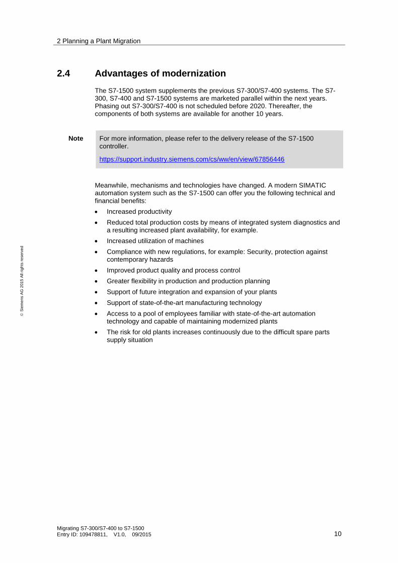
Table 5-15
S7-300 CPUs/ S7-400 CPUs
S7-1500 CPUs
OB100: Restart OB101: Restart OB102: Cold start (only for S7-400)
Up to 100, OB_Startup executed in succession within one call phase
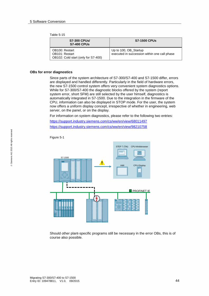
OBs for error diagnostics
Since parts of the system architecture of S7-300/S7-400 and S7-1500 differ, errors are displayed and handled differently. Particularly in the field of hardware errors, the new S7-1500 control system offers very convenient system diagnostics options. While for S7-300/S7-400 the diagnostic blocks offered by the system (report system error, short SFM) are still selected by the user himself, diagnostics is automatically integrated in S7-1500. Due to the integration in the firmware of the CPU, information can also be displayed in STOP mode. For the user, the system now offers a uniform display concept, irrespective of whether in engineering, web server, on the panel, or on the display.
For information on system diagnostics, please refer to the following two entries:
https://support.industry.siemens.com/cs/ww/en/view/68011497
https://support.industry.siemens.com/cs/ww/en/view/98210758
Figure 5-1
STEP 7 (TIA)
HMI CPU-Display
CPU-Webbrowser
PROFINET IE
S7-1500
Should other plant-specific programs still be necessary in the error OBs, this is of course also possible.
5 Software Conversion
Migrating S7-300/S7-400 to S7-1500 Entry ID: 109478811, V1.0, 09/2015 45
S
iem
en
s A
G 2
01
5 A
ll ri
gh
ts r
ese
rve
d
5.3.2 Function blocks and functions, data blocks
For compatibility reasons, STEP 7 V5.5 and STEP 7 TIA Portal does not differ with regards to basic functions, but in some details. These are describe in detail in the programming guideline.
https://support.industry.siemens.com/cs/ww/en/view/81318674
Functions (FC)
For functions in STEP 7 (FCs), appropriate input and output signals can be declared and transferred to the FC when they are called. In addition, the FC can provide a direct return value of the function. Temporary variables can be declared in an FC.
Function blocks (FB)
For function blocks in STEP 7 (FBs), appropriate input and output signals can also be declared and transferred to the FB when they are called. During the call, an instance (possibly multi-instance) is assigned to each FB as a memory in which the values of its tags are stored for processing. Static and temporary local variables can be declared in a STEP 7 FB.
Data block (DB)
Data blocks are used for saving relevant data. In STEP 7 V5.5 as well as in STEP 7 TIA Portal there are global data blocks as well as instance data blocks. However, a major difference lies in using or handling the data blocks. While in STEP 7 V5.5, only DBs with up to 64 Kbytes can be used, blocks of up to 10 Mbytes size can be created and used in TIA Portal. This depends on the property of the blocks (optimized/non-optimized), the CPU and the available storage space.

5 Software Conversion
Migrating S7-300/S7-400 to S7-1500 Entry ID: 109478811, V1.0, 09/2015 46
S
iem
en
s A
G 2
01
5 A
ll ri
gh
ts r
ese
rve
d
5.3.3 Differences between STEP 7 V5.5 and STEP 7 TIA Portal
Basic functions are equal in STEP 7 V5.5 and STEP 7 TIA Portal. However, there are some improvements in the detail regarding handling and programming. Subsequently, there is an extract of some functions realized in the STEP 7 TIA Portal.
General functions
Table 5-16
STEP 7 TIA Portal Description/advantage
Possibility of performing traces Before, traces were only possible at great expense - with additional modules/additional wiring. Now the function is integrated in software and CPU-FW

5 Software Conversion
Migrating S7-300/S7-400 to S7-1500 Entry ID: 109478811, V1.0, 09/2015 47
S
iem
en
s A
G 2
01
5 A
ll ri
gh
ts r
ese
rve
d
STEP 7 TIA Portal Description/advantage
Motion functions integrated -> PLCopen blocks
Motion functions were previously not integrated in standard CPUs
Speed axes, positioning axes and synchronization axes are available.
PID compact regulator integrated (PID_Compact, PID_3Step, PID_Temp) PID basic controller contained for compatibility reasons

5 Software Conversion
Migrating S7-300/S7-400 to S7-1500 Entry ID: 109478811, V1.0, 09/2015 48
S
iem
en
s A
G 2
01
5 A
ll ri
gh
ts r
ese
rve
d
STEP 7 TIA Portal Description/advantage
Recipes/archive as CSV file, via web server of the CPU
Recipes as .csv file did previously not exist on the CPU
Security Integrated – more protection levels available
For S7-300/S7-400 there were only 2 protection levels. Now it is possible to better assign the access levels.
Download in run (memory reserve existing), all changes activated at the same time
Download in run was previously also possible, however, the user needed to be aware of the order to prevent the CPU from going to STOP

5 Software Conversion
Migrating S7-300/S7-400 to S7-1500 Entry ID: 109478811, V1.0, 09/2015 49
S
iem
en
s A
G 2
01
5 A
ll ri
gh
ts r
ese
rve
d
STEP 7 TIA Portal Description/advantage
Library concept Libraries were already possible for STEP 7 V5.5, however, without versioning. Blocks, data types, screens and entire stations can be stored.
System status list (SSL) was replaced by a new system diagnostics
The diagnostic options for S7-1500 and TIA Portal were reworked entirely. System diagnostics has already been implemented. The user no longer needs to pay attention to blocks such as “Report system error”.

5 Software Conversion
Migrating S7-300/S7-400 to S7-1500 Entry ID: 109478811, V1.0, 09/2015 50
S
iem
en
s A
G 2
01
5 A
ll ri
gh
ts r
ese
rve
d
Programming
Table 5-17
STEP 7 TIA Portal Description/advantage
All instructions exist in all programming languages
In STEP 7 V5.5, not all of the instructions were available in FBD/LAD
Same performance for all programming languages
In TIA Portal, all programming languages are directly compiled into machine code and therefore, they all provide the same performance.
Symbols and comments are saved in CPU -> Complete upload possible
Now it is possible to perform a complete system extraction
Hardware identifier and hardware constant – simplified handling of system functions
The reintroduced “Hardware Identifier” and hardware constants enable a symbolic programming without (logic) I/O addresses.
Entry into the settings of the module
Entry of hardware constant into the tag table
Example interconnection at a block
Several branches within one network
In order to use networks as logic units it is possible to insert several branches into a network
Slicing possible – access to elements of a larger data type
A slice access may look as follows, e.g: .%X0 for Bool, .%B0 for byte, .%W0 for word, .%D0 for double word

5 Software Conversion
Migrating S7-300/S7-400 to S7-1500 Entry ID: 109478811, V1.0, 09/2015 51
S
iem
en
s A
G 2
01
5 A
ll ri
gh
ts r
ese
rve
d
STEP 7 TIA Portal Description/advantage
Slicing is also possible in FBD / LAD / SCL – no programming necessary in STL
The output tag is one WORD. One respective bit of the respective word is accessed here.
Indirect addressing also possible in FBD / LAD / SCL
implied type conversion

5 Software Conversion
Migrating S7-300/S7-400 to S7-1500 Entry ID: 109478811, V1.0, 09/2015 52
S
iem
en
s A
G 2
01
5 A
ll ri
gh
ts r
ese
rve
d
STEP 7 TIA Portal Description/advantage
Simplified handling of Send/Receive communication by means of a wizard
Simplified “Calculate”
Simplified mathematical function (selectable data type)
5 Software Conversion
Migrating S7-300/S7-400 to S7-1500 Entry ID: 109478811, V1.0, 09/2015 53
S
iem
en
s A
G 2
01
5 A
ll ri
gh
ts r
ese
rve
d
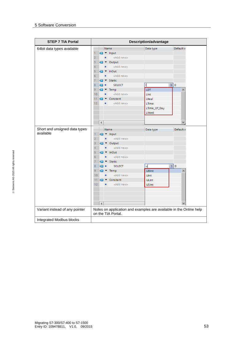
STEP 7 TIA Portal Description/advantage
64bit data types available
Short and unsigned data types available
Variant instead of any pointer Notes on application and examples are available in the Online help on the TIA Portal.
Integrated Modbus blocks

5 Software Conversion
Migrating S7-300/S7-400 to S7-1500 Entry ID: 109478811, V1.0, 09/2015 54
S
iem
en
s A
G 2
01
5 A
ll ri
gh
ts r
ese
rve
d
5.3.4 Differences in the hardware of S7-300/S7-400 and S7-1500
Apart from many innovations in the internal processing (firmware) as well as the improved backplane bus, two hardware properties of S7-1500 need to be highlighted. At the front of the CPU, a display exists which can be taken off. Therefore, not only the LEDs are available at the CPU as rough status information, but a detailed display, for example for firmware versions, diagnostics, interface settings. The size of the display depends on the CPU – for the CPUs 1511 and 1513 there is a thin, and for CPUs 1515,1516,1517,1518 a wide display. Since the CPUs 1510, 1512 and the open controller are part of the ET200SP series, they come without display.
Figure 5-2 Displays of the CPUs 1511/1513 or 1515/1516/1517/1518
Another change between both S7-CPU generations is the SIMATIC memory card (SMC). While for S7-300 the micro memory card (MMC) could only be written to with a special prommer due to the SIMATIC file system (internal or external), a standard card reader can now be used for the SMC. Furthermore, the available memory has increased considerably - now cards up to 32 GB can be used which enables creating much more complex programs.
Note You can delete and create folders on the SMC. However, do not format the card with the Windows card reader, otherwise, it becomes unusable for the CPU.
Further information regarding the SMC is available in the system manual on the S7-1500 in chapter “SIMATIC Memory Card” at: https://support.industry.siemens.com/cs/ww/en/view/59191792

5 Software Conversion
Migrating S7-300/S7-400 to S7-1500 Entry ID: 109478811, V1.0, 09/2015 55
S
iem
en
s A
G 2
01
5 A
ll ri
gh
ts r
ese
rve
d
5.4 Programming sequential controls – GRAPH in STEP 7 V5.x and TIA Portal
Note Programming sequential controls – GRAPH will be described in a later version of this guide.

6 The most important Recommendations
Migrating S7-300/S7-400 to S7-1500 Entry ID: 109478811, V1.0, 09/2015 56
S
iem
en
s A
G 2
01
5 A
ll ri
gh
ts r
ese
rve
d
6 The most important Recommendations
6.1 Contacts in the region
Find a SIEMENS contact in your region:
www.siemens.de/yourcontact
6.2 Services offered by Siemens
Migration of obsolete control systems is the prerequisite for high availability over the entire life cycle of your plant. Siemens offers comprehensive migration support for typical fields of application. We support you from the idea stage to planning and implementation. The scope of services includes migration or temporary support of your migration projects.
Your benefits at a glance:
Cost and time savings in the implementation phase
Optimum preparation of your migration
High degree of planning reliability
Your path to the Technical Support
https://support.industry.siemens.com/sc/en/sc/3082
Services and overview
https://support.industry.siemens.com/sc/en/sc/3083
Furthermore on demand, we offer you personal, individual support – exactly tailored to your specific requirements:
Clarifying in the run-up to migration and checking the core functionality via your Siemens personal contact: www.siemens.de/industry/contact
Complete service from consultation to completing the project within the framework of our SIMATIC Migration Services: http://www.siemens.de/fa-services
6.3 Solution Partner
The Partner Finder allows you to find one of our qualified Solution Partners to solve your migration task.
Solution Partner Program www.siemens.de/automation/solutionpartner

6 The most important Recommendations
Migrating S7-300/S7-400 to S7-1500 Entry ID: 109478811, V1.0, 09/2015 57
S
iem
en
s A
G 2
01
5 A
ll ri
gh
ts r
ese
rve
d
6.4 References and online documents
6.4.1 Important information
Table 6-1
Topic pages Link
Migration topic page 83558085
Table 6-2
Manuals on S7-300 Link
SIMATIC S7-300 CPU 31xC and CPU 31x: Technical specifications 12996906
SIMATIC S7-300 CPU 31xC and CPU 31x: Installation 13008499
SIMATIC S7-300 Instruction list of S7-300-CPUs and ET 200-CPUs 31977679
SIMATIC S7-300 Module data 8859629
Table 6-3
Manuals on S7-400 Link
SIMATIC S7-400, S7-400 Automation System, Module Data 1117740
SIMATIC S7-400, S7-400 Automation System, CPU Specifications 53385241
Automation System S7-400 Hardware and Installation 1117849
Automation System S7-400 Configuration and Use 22586851
Table 6-4 – S7-1500 manuals and STEP 7 manuals in TIA Portal
S7-1500 manuals and STEP 7 manuals in TIA Portal Link
SIMATIC Programming device SIMATIC Field PG M4 67463270
SIMATIC S7-1500, ET 200MP Automation System 59191792
SIMATIC S7-1500 / ET 200MP Manual Collection 86140384
Programming Guideline for S7-1200/S7-1500 81318674
SIMATIC S7-1200 / S7-1500 Comparison list for programming languages
86630375
SIMATIC S7-1500 Getting Started 71704272
SIMATIC S7-1500 Cycle and Response Times 59193558
TIA Selection Tool Link
SIMATIC S7-1500 / ET 200MP Manual Collection 86140384
SIMATIC S7-1500 Structure and Use of the CPU Memory 59193101

7 Appendix
Migrating S7-300/S7-400 to S7-1500 Entry ID: 109478811, V1.0, 09/2015 58
S
iem
en
s A
G 2
01
5 A
ll ri
gh
ts r
ese
rve
d
7 Appendix
7.1 SIMATIC S7-300/S7-400, S7-1500 components and HMI in comparison
The following tables show the respective S7-1500 equivalent to the listed SIMATIC S7-300/S7-400 module in terms of content.
It is essential that you note the following:
Note The content of this table is for reference only!
In addition to the technical features listed in the tables, the components have more technical properties which differ in some cases. Which technical features are important and relevant to the respective plant / plant part can only be identified through careful analysis of the installed base and must be determined in this migration phase. See also Planning the migration phases.
This means: The respectively mentioned SIMATIC S7-1500 hardware component must not automatically be considered as equal substitute for the mentioned SIMATIC S7-300/S7-400 component. It is the user's responsibility to consider the technical characteristics (e.g., limits) of the SIMATIC S7 module and to check whether these parameters are relevant to the customer application (plant) and complied with.
Examples of relevant technical parameters:
Power supply
Signal voltage
Frequency
Connection to common potential or channel separation
Number of channels
Load current
Contact load
Switching rate
etc. ...

7 Appendix
Migrating S7-300/S7-400 to S7-1500 Entry ID: 109478811, V1.0, 09/2015 59
S
iem
en
s A
G 2
01
5 A
ll ri
gh
ts r
ese
rve
d
7.1.1 CPU modules
Note The content of the following table is used for orientation only!
Please note the general information in this chapter: SIMATIC S7-300/S7-400, S7-1500 components and HMI in comparison.
The TIA Selection Tool offers support for migrating S7-300/S7-400 to S7-1500: http://www.siemens.de/tia-selection-tool
Table 7-1
S7-300 Description S7-1500 Description
6ES7 312-1AE13-0AB0 CPU 312-1 6ES7 511-1AK01-0AB0 CPU 1511
6ES7 312-1AE14-0AB0 CPU 312-1 6ES7 511-1AK01-0AB0 CPU 1511
6ES7 312-5BE03-0AB0 CPU 312C 6ES7 215-1AG40-0XB0 CPU 1215C
6ES7 312-5BF04-0AB0 CPU 312C 6ES7 215-1AG40-0XB0 CPU 1215C
6ES7 313-5BF03-0AB0 CPU 313C 6ES7 511-1CK00-0AB0 CPU 1511C
6ES7 313-5BG04-0AB0 CPU 313C 6ES7 511-1CK00-0AB0 CPU 1511C
6ES7 313-6CF03-0AB0 CPU 313C-2DP 6ES7 511-1CK00-0AB0 CPU 1511C
6ES7 313-6CG04-0AB0 CPU 313C-2DP 6ES7 511-1CK00-0AB0 CPU 1511C
6ES7 313-6BF03-0AB0 CPU 313C-2PtP 6ES7 511-1CK00-0AB0 CPU 1511C
6ES7 313-6BG04-0AB0 CPU 313C-2PtP 6ES7 511-1CK00-0AB0 CPU 1511C
6ES7 314-1AG13-0AB0 CPU 314 6ES7 511-1AK01-0AB0 CPU 1511
6ES7 314-1AG14-0AB0 CPU 314 6ES7 511-1AK01-0AB0 CPU 1511
6ES7 314-6CG03-0AB0 CPU 314C-2DP 6ES7 512-1CK00-0AB0 CPU 1512C
6ES7 314-6CH04-0AB0 CPU 314C-2DP 6ES7 512-1CK00-0AB0 CPU 1512C
6ES7 314-6EH04-0AB0 CPU 314C-2PN/DP 6ES7 512-1CK00-0AB0 CPU 1512C
6ES7 314-6BG03-0AB0 CPU 314C-2Ptp 6ES7 512-1CK00-0AB0 CPU 1512C
6ES7 314-6BH04-0AB0 CPU 314C-2Ptp 6ES7 512-1CK00-0AB0 CPU 1512C
6ES7 315-2AG10-0AB0 CPU 315-2DP 6ES7 513-1AL01-0AB0 CPU 1513-1PN
6ES7 315-2AH10-0AB0 CPU 315-2DP 6ES7 513-1AL01-0AB0 CPU 1513-1PN
6ES7 315-2EH13-0AB0 CPU 315-2PNDP 6ES7 515-2AM01-0AB0 CPU 1515-2PN
6ES7 315-2EH14-0AB0 CPU 315-2PN/DP 6ES7 515-2AM01-0AB0 CPU 1515-2PN
6ES7 315-6FF01-0AB0 CPU 315F-2DP 6ES7 513-1FL01-0AB0 CPU 1513F-1PN
6ES7 315-6FF04-0AB0 CPU 315 F-2DP 6ES7 513-1FL01-0AB0 CPU 1513F-1PN
6ES7 315-2FH13-0AB0 CPU 315F-2PN/DP 6ES7 515-2FM01-0AB0 CPU 1515F-2PN
6ES7 315-2FJ14-0AB0 CPU 315F-2PN/DP 6ES7 515-2FM01-0AB0 CPU 1515F-2PN
6ES7 317-2AJ10-0AB0 CPU 317-2 6ES7 516-3AN01-0AB0 CPU 1516-3PN/DP
6ES7 317-2AK14-0AB0 CPU 317-2 6ES7 516-3AN01-0AB0 CPU 1516-3PN/DP
6ES7 317-2EK13-0AB0 CPU 317-2PN/DP 6ES7 516-3AN01-0AB0 CPU 1516-3PN/DP
6ES7 317-2EK14-0AB0 CPU 317-2PN/DP 6ES7 516-3AN01-0AB0 CPU 1516-3PN/DP
6ES7 317-6FF03-0AB0 CPU 317F-2 6ES7 516-3FN01-0AB0 CPU 1516F-3PN/DP
6ES7 317-6FF04-0AB0 CPU 317F-2 6ES7 516-3FN01-0AB0 CPU 1516F-3PN/DP
6ES7 317-2FK13-0AB0 CPU 317F-2PN/DP 6ES7 516-3FN01-0AB0 CPU 1516F-3PN/DP

7 Appendix
Migrating S7-300/S7-400 to S7-1500 Entry ID: 109478811, V1.0, 09/2015 60
S
iem
en
s A
G 2
01
5 A
ll ri
gh
ts r
ese
rve
d
S7-300 Description S7-1500 Description
6ES7 317-2FK14-0AB0 CPU 317F-2PN/DP 6ES7 516-3FN01-0AB0 CPU 1516F-3PN/DP
6ES7 318-3EL00-0AB0 CPU 319-3PN/DP 6ES7 517-3AP00-0AB0 CPU 1517-3PN/DP
6ES7 318-3EL01-0AB0 CPU 319-3PN/DP 6ES7 517-3AP00-0AB0 CPU 1517-3PN/DP
6ES7 318-3FL00-0AB0 CPU 319F-3PN/DP 6ES7 517-3FP00-0AB0 CPU 1517F-3PN/DP
6ES7 318-3FL01-0AB0 CPU 319F-3PN/DP 6ES7 517-3FP00-0AB0 CPU 1517F-3PN/DP
6ES7 151-7AA20-0AB0 IM 151-7 CPU 6ES7510-1DJ01-0AB0 CPU 1510SP-1PN
6ES7 151-7AA21-0AB0 IM 151-7 CPU 6ES7510-1DJ01-0AB0 CPU 1510SP-1PN
6ES7 151-7AB00-0AB0 IM 151-7 CPU FO 6ES7512-1DK01-0AB01 CPU 1510SP-1PN
6ES7 151-7FA20-0AB0 IM 151-7F-CPU 6ES7 510-1SJ01-0AB0 CPU 1510SP F-1PN
6ES7 151-7FA21-0AB0 IM 151-7F-CPU 6ES7 510-1SJ01-0AB0 CPU 1510SP F-1PN
6ES7 151-8AB00-0AB0 IM 151-8 PN/DP CPU 6ES7 512-1DK01-0AB0 CPU 1512SP-1PN
6ES7 151-8AB01-0AB0 IM 151-8 PN/DP CPU 6ES7 512-1DK01-0AB0 CPU 1512SP-1PN
6ES7 151-8FB00-0AB0 IM 151-8F PN/DP CPU 6ES7 512-1SK01-0AB0 CPU 1512SP F-1PN
6ES7 151-8FB01-0AB0 IM 151-8F PN/DP CPU 6ES7 512-1SK01-0AB0 CPU 1512SP F-1PN
Table 7-2
S7-400 Description S7-1500 Description
6ES7 412-1XJ05-0AB0 CPU 412-1MPI/DP 6ES7 513-1AL01-0AB0 CPU 1513-1PN
6ES7 412-2XJ05-0AB0 CPU 412-2 6ES7 515-2AM01-0AB0 CPU 1515-2PN
6ES7 412-2EK06-0AB0 CPU 414-2PN/DP 6ES7 516-3AN01-0AB0 CPU 1516-3PN/DP
6ES7 414-2XK05-0AB0 CPU 414-2 6ES7 517-3AP00-0AB0 CPU 1517-3PN/DP
6ES7 414-3XM05-0AB0 CPU414-3 6ES7 518-4AP00-0AB0 CPU 1518-4PN/DP
6ES7 414-3EM05-0AB0 CPU 414-3PN/DP 6ES7 518-4AP00-0AB0 CPU 1518-4PN/DP
6ES7 414-3EM06-0AB0 CPU 414-3PN/DP 6ES7 518-4AP00-0AB0 CPU 1518-4PN/DP
6ES7 414-3FM06-0AB0 CPU 414F-3PN/DP 6ES7 518-4FP00-0AB0 CPU 1518F-4PN/DP
6ES7 416-2XN05-0AB0 CPU 416-2 6ES7 518-4AP00-0AB0 CPU 1518-4PN/DP
6ES7 416-3XR05-0AB0 CPU 416-3 6ES7 518-4AP00-0AB0 CPU 1518-4PN/DP
6ES7 416-3ER05-0AB0 CPU 416-3PN/DP 6ES7 518-4AP00-0AB0 CPU 1518-4PN/DP
6ES7 416-3ES06-0AB0 CPU 416-3PN/DP 6ES7 518-4AP00-0AB0 CPU 1518-4PN/DP
6ES7 416-2FN05-0AB0 CPU 416F-2DP 6ES7 518-4FP00-0AB0 CPU 1518F-4PN/DP
6ES7 416-3FR05-0AB0 CPU 416F-3PN/DP 6ES7 518-4FP00-0AB0 CPU 1518F-4PN/DP
6ES7 416-3FS06-0AB0 CPU 416F-3PN/DP 6ES7 518-4FP00-0AB0 CPU 1518F-4PN/DP
6ES7 417-4XT05-0AB0 CPU 417-4 6ES7 518-4AP00-0AB0 CPU 1518-4PN/DP
*) Please note the information in the „Selecting the CPU“ chapter, especially the different size of memory
1 CPU 1512 can only be used in combination with suitable bus adapter

7 Appendix
Migrating S7-300/S7-400 to S7-1500 Entry ID: 109478811, V1.0, 09/2015 61
S
iem
en
s A
G 2
01
5 A
ll ri
gh
ts r
ese
rve
d
7.1.2 Comparison of software / hardware properties
The tables below give you an overview of the properties available in the individual CPU types
CPU hardware properties
Table 7-3
Property S7-300/S7-400 S7-1500
Display no
Yes, for 1511, 1513-1518
Display for fail-safe CPU shows - Safety mode activated/deactivated - Signature - Time stamp of last changes Safety program - Diagnostics
no yes
Memory Card with standard file system no yes
PPI interface no no
MPI interface yes no
DP interface yes yes
DP interface with PROFIsafe yes yes
1.PN interface with base functions yes yes
1.PN interface with IRT yes yes
1.PN interface with PROFIsafe yes yes
2. PN interface with base functions no yes
3. PN interface with base functions no yes
CPU properties
Table 7-4
Property S7-300/S7-400 S7-1500
Process image yes yes
Multi-process image yes, S7-400 yes
Flexible number assignment for OBs no yes
Flexible number assignment F-OB no yes
OB1 yes yes
OB1x yes yes
Up to 50 process alarm OBs up to 40 yes
up to 20 cyclic interrupts with different priorities no yes
Clock synchronized OBs yes yes
Several cyclic, startup, process OBs no yes
Several F-OBs for better program structure no yes

7 Appendix
Migrating S7-300/S7-400 to S7-1500 Entry ID: 109478811, V1.0, 09/2015 62
S
iem
en
s A
G 2
01
5 A
ll ri
gh
ts r
ese
rve
d
CPU programming languages general
Table 7-5
Properties S7-300/S7-400 S7-1500
Symbolic programming yes yes
STL yes yes
FUP / F-FBD yes yes
LAD / F-LAD yes yes
SCL yes yes
S7-GRAPH yes yes
HiGraph yes no
CFC yes no, scheduled
Same functions in all programming languages no yes
SFBs yes yes
SFCs yes yes
S7 timer yes yes
S7 F timer yes yes
ICE counter yes yes
S7 counter yes yes
Edge evaluation yes yes
Global DBs yes yes
Instance DB yes yes
FBs yes yes
FCs yes yes
System status list (SSL) yes entirely new solution
64bit data types no yes
Short/U short data types no yes
Implied type conversion no yes
Slice access no yes
Calculate box no yes
Indirect addressing FBD/LAD no yes
CPU programming languages FBD/LAD
Table 7-6
Property S7-300/S7-400 S7-1500
Several branches within one network no yes
Expandable mathematic block – more than 2 inputs no yes
Expandable MOVE block – more than 2 outputs no yes
CALCULATE block for complex mathematical expressions
no yes
Implied data type conversion no yes
Automatic switchover for mathematic block no yes
Deactivating ENO no yes
JMP_LIST no yes

7 Appendix
Migrating S7-300/S7-400 to S7-1500 Entry ID: 109478811, V1.0, 09/2015 63
S
iem
en
s A
G 2
01
5 A
ll ri
gh
ts r
ese
rve
d
Property S7-300/S7-400 S7-1500
Concept for libraries with versioning no yes
Concept for F libraries with versioning no yes
Data type D-WORD for safety program no yes, with UDT
Data type D-INT for safety program no yes
CPU online functions
Table 7-7
Property S7-300/S7-400 S7-1500
Consistent download of all changes no yes
Download in Run mode yes yes, activation of the modifications, actual values of the DBs are not overwritten
Upload of hardware yes - restricted yes
Upload of entire program yes - restricted yes
Trace no yes
Symbolic information saved in the CPU no yes
CPU security functions
Table 7-8
Property S7-300/S7-400 S7-1500
Knowhow protection/block privacy STD blocks yes yes
Knowhow protection/block privacy F blocks yes yes
Copy protection yes yes
Access protection no yes
Additional F access protection no yes
Expanded access protection (protection layer) also for HMI
no yes
Integrity check no yes
CPU communication
Table 7-9
Property S7-300/S7-400 S7-1500
MODBUS TCP no - separate library necessary
yes
MODBUS RTU yes yes

7 Appendix
Migrating S7-300/S7-400 to S7-1500 Entry ID: 109478811, V1.0, 09/2015 64
S
iem
en
s A
G 2
01
5 A
ll ri
gh
ts r
ese
rve
d
CPU diagnostic functions
Table 7-10
Property S7-300/S7-400 S7-1500
Integrated system diagnostic no yes
Identical diagnostics at web server, HMI, display and engineering
no yes
CPU web server
Table 7-11
Property S7-300/S7-400 S7-1500
File explorer no yes
Archive and recipe handling via web server no yes
CPU technology functions
Table 7-12
Property S7-300/S7-400 S7-1500
PID compact controller integrated no yes
Motion control integrated according to PLCopen no yes
Trace no yes

7 Appendix
Migrating S7-300/S7-400 to S7-1500 Entry ID: 109478811, V1.0, 09/2015 65
S
iem
en
s A
G 2
01
5 A
ll ri
gh
ts r
ese
rve
d
7.1.3 Digital modules S7-300
Note The content of this table is for reference only!
Please note the general information in this chapter:
SIMATIC S7-300/S7-400, S7-1500 components and HMI in comparison
Table 7-13
S7-300 Description S7-1500 Description
Digital input modules
6ES7 321-1BH02-0AA0 16DE,DC24V 6ES7 521-1BH00-0AB0
or 6ES7 521-1BH10-0AA0
16DE,24VDC, HF 16DE,24VDC, BA
6ES7 321-1BH10-0AA0 16DE,DC24V 6ES7 521-1BH00-0AB0 16DE,24VDC, HF
6ES7 321-7BH01-0AB0 16DE,DC24V,DA,PA 6ES7 521-1BH00-0AB0 16DE,24VDC, BA
6ES7 321-1BH50-0AA0 16DE,DC24V 6ES7 521-1BH50-0AB0 16DE,24VDC, SRC BA
6ES7 321-1BL00-0AA0 32DE,DC24V 6ES7 521-1BL00-0AB0 or 6ES7 521-1BL10-0AA0
16DE,24VDC, HF or 32DE,24VDC, BA
6ES7 321-1FH00-0AA0 16DE,AC120/230V 6ES7 521-1FH00-0AA0 16DE,230VAC, BA
6ES7 321-1FF01-0AA0 8DE,AC120/230V 6ES7 521-1FH00-0AA0 16DE,230VAC, BA
6ES7 321-1FF10-0AA0 8DE,UC120/230V 6ES7 521-1FH00-0AA0 16DE,230VAC, BA
Digital output modules
6ES7 322-1BH01-0AA0 16DA,DC24V/0.5A 6ES7 522-1BH01-0AA0
or 6ES7 522-1BH00-0AB0
16DA,24VDC/0.5A,BA or
16DA,24VDC/0.5A,ST
6ES7 322-8BF00-0AB0 8DA,DC24V/0.5A 6ES7 522-1BH00-0AB0 16DA,24VDC/0.5A,ST
6ES7 322-1BH10-0AA0 16DA,DC24V/0.5A High Speed
6ES7 522-1BH00-0AB0 16DA.24VDC/0.5A,ST
6ES7 322-1BL00-0AA0 32DA,DC24V/0.5A 6ES7 522-1BL00-0AB0 or
6ES7 522-1BL10-0AA0
32DA,24VDC/0.5A,ST
6ES7 322-7BH01-0AB0 8DA,DC24V,0.5A 6ES7 522-1BF00-0AB0 8DA,24VDC/2A HF
6ES7 322-1FH00-0AA0 16DA,AC120/230V 6ES7 522-5FF00-0AB0 8DA,230VAC/2A, ST
6ES7 322-1FF01-0AA0 8DA,AC120/230V 6ES7 522-5FF00-0AB0 8DA,230VAC/2A, ST
6ES7 322-5FF00-0AA0 8DA,AC120/230V 6ES7 522-5FF00-0AB0 8DA,230VAC/2A, ST
6ES7 322-1HH01-0AA0 16DA,AC120/230V,Relay
6ES7 522-5FF00-0AB0 8DA,230VAC/2A, ST
Digital input/output modules
6ES7 323-1BL00-0AA0 16DE/16DA 6ES7 523-1BL00-0AA0 16DI,24VDC/16DA,24VDC/0.5A BA
6ES7 323-1BH01-0AA0 8DE/8DO 6ES7 523-1BL00-0AA0 16DI,24VDC/16DA,24VDC/0.5A BA

7 Appendix
Migrating S7-300/S7-400 to S7-1500 Entry ID: 109478811, V1.0, 09/2015 66
S
iem
en
s A
G 2
01
5 A
ll ri
gh
ts r
ese
rve
d
S7-300 Description S7-1500 Description
Labeling strips for S7-300 and S7-1500
6ES7 392-2AX10-0AA0
6ES7 392-2BX10-0AA0
6ES7 392-2CX10-0AA0
6ES7 392-2DX10-0AA0
petrol bright beige yellow red Labeling strip for 40-pin front connector
6ES7 592-2AX00-0AA0 Labeling sheets for 35mm wide S7-1500 modules
6ES7 592-1AX00-0AA0 Labeling sheets for 25mm wide S7-1500 modules
* Unlike the 35mm wide modules whose delivery has already started, the 25mm wide modules feature no parameters and diagnostics.

7 Appendix
Migrating S7-300/S7-400 to S7-1500 Entry ID: 109478811, V1.0, 09/2015 67
S
iem
en
s A
G 2
01
5 A
ll ri
gh
ts r
ese
rve
d
7.1.4 Digital modules S7-400
Note The content of this table is for reference only!
Please note the general information in this chapter:
SIMATIC S7-300/S7-400, S7-1500 components and HMI in comparison
Table 7-14
S7-400 Description S7-1500 Description
Digital input modules
6ES7 421-7BH01-0AB0 16DE,DC24V,DA,PA 6ES7 521-1BH00-0AB0 16DI,24VDC, HF
6ES7 421-1BL01-0AA0 32DE,DC24V 6ES7 521-1BL10-0AA0 32DI,24VDC,BA
6ES7 421 1FH20-0AA0 16DE,UC120/230V 6ES7 521-1FH00-0AB0 16DI,230VAC, BA
Digital output modules
6ES7 422-7DH00-0AB0 32DA,DC24V/0.5A 6ES7 522-1BH00-0AB0 16DA, 24VDC/0.5A, ST
6ES7 422-1BL00-0AA0 32DA,DC24V/0.5A 6ES7 522-1BL00-0AB0 or 6ES7 522-1BL10-0AA0
32DQ,24VDC/0.5A,ST or 32DQ,24VDC/0.5A,BA
6ES7 422-1BH11-0AA0 16DA,DC24V/AA 6ES7 522-1BF00-0AB0 8DA,24VDC/2A,HF
6ES7 422-1FH00-0AA0 16DA,AC120/230V/2A 6ES7 522 5FF00-0AB0 8DA,230VAC/2A (Triac)
6ES7 422-1HH00-0AA0 16RA,DC60V/230V 6ES7 522-5FF00-0AB0 8DA,230VAC/2A (Triac)
* Unlike the 35mm wide modules whose delivery has already started, the 25mm wide modules feature no parameters and diagnostics.
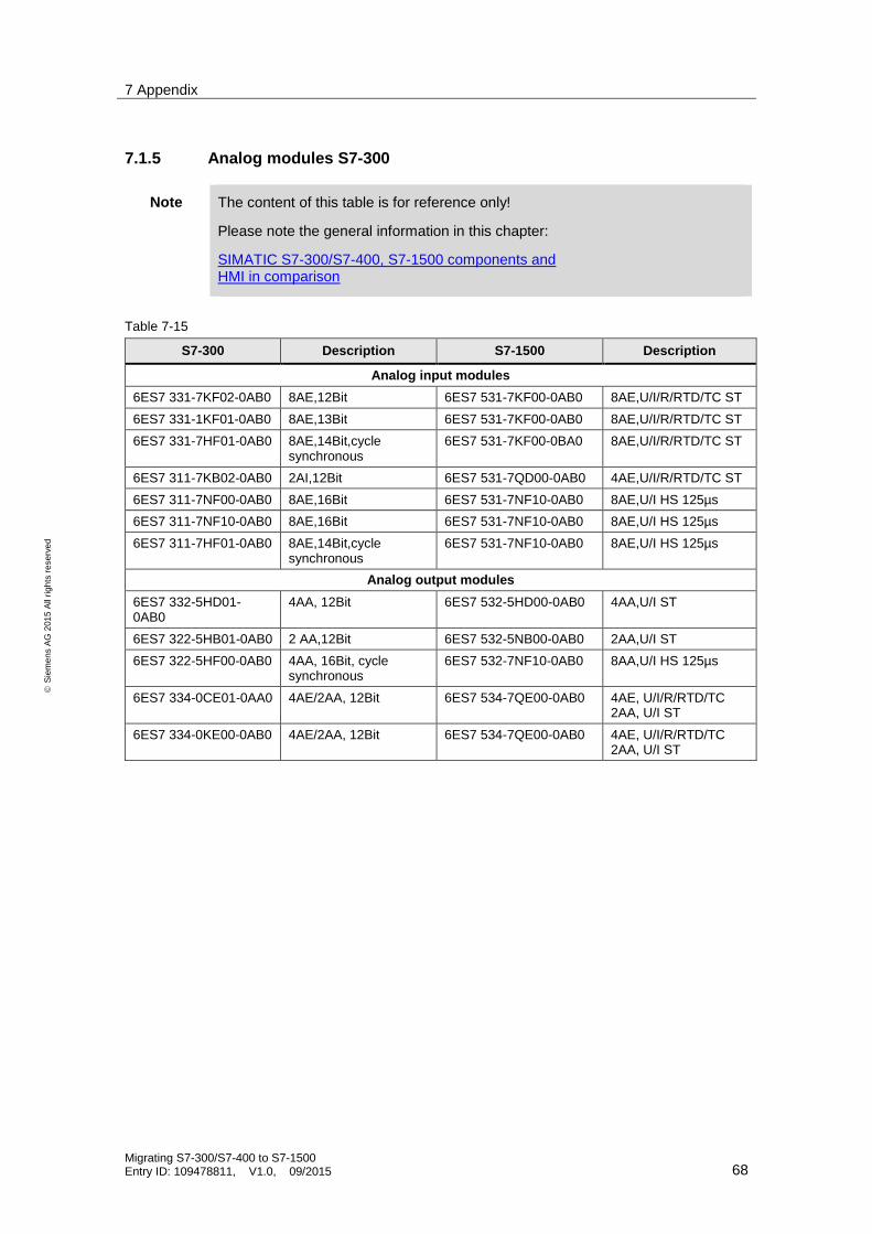
7 Appendix
Migrating S7-300/S7-400 to S7-1500 Entry ID: 109478811, V1.0, 09/2015 68
S
iem
en
s A
G 2
01
5 A
ll ri
gh
ts r
ese
rve
d
7.1.5 Analog modules S7-300
Note The content of this table is for reference only!
Please note the general information in this chapter:
SIMATIC S7-300/S7-400, S7-1500 components and HMI in comparison
Table 7-15
S7-300 Description S7-1500 Description
Analog input modules
6ES7 331-7KF02-0AB0 8AE,12Bit 6ES7 531-7KF00-0AB0 8AE,U/I/R/RTD/TC ST
6ES7 331-1KF01-0AB0 8AE,13Bit 6ES7 531-7KF00-0AB0 8AE,U/I/R/RTD/TC ST
6ES7 331-7HF01-0AB0 8AE,14Bit,cycle synchronous
6ES7 531-7KF00-0BA0 8AE,U/I/R/RTD/TC ST
6ES7 311-7KB02-0AB0 2AI,12Bit 6ES7 531-7QD00-0AB0 4AE,U/I/R/RTD/TC ST
6ES7 311-7NF00-0AB0 8AE,16Bit 6ES7 531-7NF10-0AB0 8AE,U/I HS 125µs
6ES7 311-7NF10-0AB0 8AE,16Bit 6ES7 531-7NF10-0AB0 8AE,U/I HS 125µs
6ES7 311-7HF01-0AB0 8AE,14Bit,cycle synchronous
6ES7 531-7NF10-0AB0 8AE,U/I HS 125µs
Analog output modules
6ES7 332-5HD01-0AB0
4AA, 12Bit 6ES7 532-5HD00-0AB0 4AA,U/I ST
6ES7 322-5HB01-0AB0 2 AA,12Bit 6ES7 532-5NB00-0AB0 2AA,U/I ST
6ES7 322-5HF00-0AB0 4AA, 16Bit, cycle synchronous
6ES7 532-7NF10-0AB0 8AA,U/I HS 125µs
6ES7 334-0CE01-0AA0 4AE/2AA, 12Bit 6ES7 534-7QE00-0AB0 4AE, U/I/R/RTD/TC 2AA, U/I ST
6ES7 334-0KE00-0AB0 4AE/2AA, 12Bit 6ES7 534-7QE00-0AB0 4AE, U/I/R/RTD/TC 2AA, U/I ST

7 Appendix
Migrating S7-300/S7-400 to S7-1500 Entry ID: 109478811, V1.0, 09/2015 69
S
iem
en
s A
G 2
01
5 A
ll ri
gh
ts r
ese
rve
d
7.1.6 Analog modules S7-400
Note The content of this table is for reference only!
Please note the general information in this chapter:
SIMATIC S7-300/S7-400, S7-1500 components and HMI in comparison
Table 7-16
S7-400 Description S7-1500 Description
Analog input modules
6ES7 431-1KF00-0AB0
8AE,13Bit,240ms, U/I/R 6ES7 531-7KF00-0AB0 or 6ES7 531-7NF10-0AB0
8AE,U/I/R/RTD/TC ST
6ES7 431-1KF10-0AB0
8AE,13Bit,240ms, U/I/R/RTD/TC
6ES7 531-7KF00-0AB0 or 6ES7 531-7NF10-0AB0
8AE,U/I/R/RTD/TC ST
6ES7 431-0HH00-0AB0
16AE,13Bit,65ms,U/I 6ES7 531-7KF00-0AB0 8AE,U/I/R/RTD/TC ST
6ES7 431-7QH00-0AB0
16AE,16Bit,25ms,DA,PA, U/I/R/RTD/TC
6ES7 531-7NF100AB0 8AE,U/I, HS 125µs
6ES7 431-7KF00-0AB0
8AE,16Bit,DA,10..100ms,U/I/TC 6ES7 531-7NF100AB0 8AE,U/I, HS 125µs
6ES7 431-1KF20-0AB0
8AE,14Bit,640µs, U/I/R 6ES7 531-7NF100AB0 8AE,U/I, HS 125µs
Analog output modules
6ES7 432-1HF00-0AB0
8AA,13Bit,0-10V/0-20mA,2ms, U/I
6ES7 532-7NF10-0AB0 8AE,U/I, HS 125µs

7 Appendix
Migrating S7-300/S7-400 to S7-1500 Entry ID: 109478811, V1.0, 09/2015 70
S
iem
en
s A
G 2
01
5 A
ll ri
gh
ts r
ese
rve
d
7.1.7 Communication modules S7-300
Note The content of this table is for reference only!
Please note the general information in this chapter:
SIMATIC S7-300/S7-400, S7-1500 components and HMI in comparison
Table 7-17
Article number Description S7-1500 Article number
Communication modules
6ES7 340-1AH02-0AE0
CP 340 RS232 6ES7 540-1AD00-0AA0 CM PtP RS232 BA
6ES7 340-1CH02-0AE0
CP 340 RS422/485 6ES7 540-1AB00-0AA0 CM PtP RS422/485 BA
6ES7 341-1AH02-0AE0
CP 341 RS232 6ES7 541-1AD00-0AB0 CM PtP RS232 HF
6ES7 341-1CH02-0AE0
CP 341 RS422/485 6ES7 541-1AB00-0AB0 CM PtP RS422/485 HF
6ES7 870-1AA01-0YA.
Modbus RTU master 6ES7 541-1AD00-0AB0 or 6ES7 541-1AB00-0AB0
CM PtP RS232 HF or CM PtP RS422/485 HF
6ES7 870-1AB01-0YA.
Modbus RTU slave 6ES7 541-1AD00-0AB0 or 6ES7 541-1AB00-0AB0
CM PtP RS232 HF or CM PtP RS422/485 HF

7 Appendix
Migrating S7-300/S7-400 to S7-1500 Entry ID: 109478811, V1.0, 09/2015 71
S
iem
en
s A
G 2
01
5 A
ll ri
gh
ts r
ese
rve
d
7.1.8 Function modules S7-300
Note The content of this table is for reference only!
Please note the general information in this chapter:
SIMATIC S7-300/S7-400, S7-1500 components and HMI in comparison
Table 7-18
Article number Description S7-1500 Description
6ES7 338-4BC01-0AB0
Signal module for reading position values for 3 SSI encoders
6ES7 551-1AB00-0AB0
TM PosInput 2 channels for incremental or SSI encoders for RS422 signals
6ES7 350-1AH03-0AE0
FM 350-1 counter module, up to 500KHz
6ES7 550-1AA00-0AB0
TM Count 2x24V channels for 24V incremental or pulse encoder
6ES7 350-2AH01-0AE0
FM 350-2, 8 channels, counter module, up to 20KHz,
6ES7 552-1AA00-0AB0
TM TimerDIDQ 16x24V, 16DE/16DA, time-controlled, PWM, over sampling or
TM Count 2x24V
6ES7 351-1AH01-0AE0
FM 351, positioning module 6ES7 550-1AA00-0AB0 or 6ES7 551-1AB00-0AB0 + SW functions in the CPU
TM Count 2x24V or TM PosInput 2
6ES7 352-1AH02-0AE0
FM352, cam control unit 6ES7 552-1AA00-0AB0 + SW functions in the CPU
TM TimerDIDQ 16x24V, 16 DE/DA, time-controlled, PWM, over sampling
6ES7 354-1AH01-0AE0
FM 354, position control Functions integrated in the CPU, I/O connection according to demand
6ES7 355-1VH10-0AE0
FM 355 S 4 channel, step and pulse
Integrated compact controller + input output modules
No fuzzy controller,
applicative controller structures possible
6ES7 355-0VH10-0AE0
FM 355 C
4 channels, continuous
Integrated compact controller + input output modules
No fuzzy controller,
applicative controller structures possible
6ES7 355-2CH00-0AE0
FM 355-2 C
4 channels, continuous
Integrated compact controller + input output modules
applicative controller structures possible
6ES7 355-2SH00-0AE0
FM355-2 S
4 channel, step and pulse
Integrated compact controller + input output modules
applicative controller structures possible
This overview is only a simplified representation of the function modules. A complete migration of the hardware requires considering the entire application.

7 Appendix
Migrating S7-300/S7-400 to S7-1500 Entry ID: 109478811, V1.0, 09/2015 72
S
iem
en
s A
G 2
01
5 A
ll ri
gh
ts r
ese
rve
d
7.1.9 Function modules S7-400
Note The content of this table is for reference only!
Please note the general information in this chapter:
SIMATIC S7-300/S7-400, S7-1500 components and HMI in comparison
Table 7-19
Article number Description S7-1500 Description
6ES7 450-1AP00-0AE0
FM 450-1, counter module, 2 channels
6ES7 550-1AA00-0AB0 TM Count 2 channels for 24V incremental or pulse encoder
6ES7 451-3AL00-0AE0
FM 451, positioning module
6ES7 550-1AA00-0AB0 or 6ES7 551-1AB00-0AB0
TM Count 2x24V or TM PosInput 2 and SW functions in the CPU
6ES7 452-1AH00-0AE0
FM 452, cam control unit 6ES7 552-1AA00-0AB0 TM TimerDIDQ 16x24V, 16 DE/DA, time-controlled, PWM, over sampling, and SW functions in the CPU
6ES7 453-3AH00-0AE0
FM 453, positioning module
Functions integrated in the CPU, I/O connection according to demand
6ES7 455-0VS00-0AE0
FM 455C, controller module, 16 channels, continuous
Integrated compact controller + input output modules
No fuzzy controller, applicative controller structures possible
6ES7 455-1VS00-0AE0
FM 455S, controller module, 16 channel, step and pulse
Integrated compact controller + input/output modules
No fuzzy controller, applicative controller structures possible
This overview is only a simplified representation of the function modules. Complete migration of the hardware requires considering the entire application.
Note The topic of function modules will be extended in a successor version of this guide.

7 Appendix
Migrating S7-300/S7-400 to S7-1500 Entry ID: 109478811, V1.0, 09/2015 73
S
iem
en
s A
G 2
01
5 A
ll ri
gh
ts r
ese
rve
d
7.1.10 Operator panels
Note The content of this table is for reference only!
Detailed information is available in the guide on migrating panels:
https://support.industry.siemens.com/cs/ww/en/view/49752044
Table 7-20
Predecessor device MLFB / article number Replacement MLFB / article number
OP 77B 6AV6641-0CA01-0AX1 KP400 Comfort 6AV2124-1DC01-0AX0
TP 177B 4" Color 6AV6642-0BD01-3AX0 KTP400 Comfort 6AV2124-2DC01-0AX0
TP 177B Mono 6AV6642-0BC01-1AX1 TP700 Comfort 6AV2124-0GC01-0AX0
TP 177B Color 6AV6642-0BA01-1AX1
TP 277 6AV6643-0AA01-1AX0
MP 177 6AV6642-0EA01-3AX0
OP 177B Mono 6AV6642-0DC01-1AX1 KP700 Comfort 6AV2124-1GC01-0AX0
OP 177B Color 6AV6642-0DA01-1AX1
OP 277 6AV6643-0BA01-1AX0
MP 277 8" Touch 6AV6643-0CB01-1AX1 TP900 Comfort 6AV2124-0JC01-0AX0
MP 277 8" Key 6AV6643-0DB01-1AX1 KP900 Comfort 6AV2124-1JC01-0AX0
MP 277 10" Touch 6AV6643-0CD01-1AX1 TP1200 Comfort 6AV2124-0MC01-0AX0
MP 277 10" Key 6AV6643-0DD01-1AX1 KP1200 Comfort 6AV2124-1MC01-0AX0
MP 377 12" Touch 6AV6644-0AA01-2AX0 TP1500 Comfort 6AV2124-0QC02-0AX0
MP 377 12" Key 6AV6644-0BA01-2AX1 KP1500 Comfort 6AV2124-1QC02-0AX0
MP 377 15" Touch 6AV6644-0AB01-2AX0 TP1900 Comfort 6AV2124-0UC02-0AX0
MP 377 19" Touch 6AV6644-0AC01-2AX1 TP2200 Comfort 6AV2124-0XC02-0AX0
Note Since the comfort panels use Widescreen as screen format, old and new operator panels can only be compared to a limited extend.

8 History
Migrating S7-300/S7-400 to S7-1500 Entry ID: 109478811, V1.0, 09/2015 74
S
iem
en
s A
G 2
01
5 A
ll ri
gh
ts r
ese
rve
d
8 History Table 8-1
Version Date Modifications
V1.0 09/2015 First version