Embed Size (px)
Citation preview
DP/N: 4LFR020-010 - v1.1 12/17/2009
®
1650 Pacific Avenue, Channel Islands CA 93033-9901 • Phone: 805 247-0226 Fax: 805 247-0669 • www.vortechsuperchargers.com • M-F 8:00AM - 4:30PM (PST)
ENGINEERING, LLC
Ford Mustang GT500VTS Twin-Screw Tuner Kit Installation Instructions
*Legal in California only for racing vehicles which may never be used upon a highway.
2007-2009 Model Years*
P/N: 4LFR020-010 v1.1, 2009-12-17©2009 Vortech Engineering, LLCAll Rights Reserved, Intl. Copr. Secured ii
FOREWORD
Take note of the following before proceeding:1. Proper installation of this supercharger kit requires general auto-motive mechanic knowledge and experience. Please browse through each step of this instruction manual prior to beginning the installation to determine if you should refer the job to a professional installer/technician. Please contact your dealer or Vortech Engineering for
possible installers in your area.2. This product was designed for use on stock (un-modified, OEM) vehicles.
The PCM (computer), engine, transmission, drive axle ratios and tire O.D. must be stock. If the vehicle or engine has been modified in any way, check with Vortech prior to installation and use of this product.
3. Use only premium grade fuel with a minimum of 91 octane (R+M/2).4. Always listen for any sign of detonation (knocking/pinging) and discontinue hard
use (no boost) until the problem is resolved.5. Vortech is not responsible for any clutch, transmission, drive-line or engine
damage.
Exclusions from Vortech warranty coverage considerations include, but not limited to:
1. Neglect, abuse, lack of maintenance, abnormal operation or improper installa-tion.
2. Continued operation with an impaired vehicle or sub-system.3. The combined use of Vortech components with other modifications such as, but
not limited to, exhaust headers, aftermarket camshafts, nitrous oxide, third party PCM programming or other such changes.
©2009 VORTECH ENGINEERING, LLC All rights reserved. No part of this publication may be reproduced, transmitted, transcribed, or translated
into another language in any form, by any means without written permission of Vortech Engineering, LLC.
STOP
This manual provides information on the installation, maintenance and service of the Vortech supercharger kit expressly designed for this vehicle. All infor-mation, illustrations and specifications contained herein are based on the lat-
est product information available at the time of this publication. Changes to the manual may be made at any time without notice. Contact Vortech Engineering for any additional information regarding this kit and any of these modifications at (805) 247-0226 8:00am-4:30pm PST.
P/N: 4LFR020-010 v1.1, 2009-12-17 ©2009 Vortech Engineering, LLC
All Rights Reserved, Intl. Copr. Securediii
TABLE OF CONTENTSFOREWORD . . . . . . . . . . . . . . . . . . . . . . . . . . . . . . . . . . . . . . . . . . . . . . . . . . . . . . . . . . . . . . . . iiTABLE OF CONTENTS . . . . . . . . . . . . . . . . . . . . . . . . . . . . . . . . . . . . . . . . . . . . . . . . . . . . . . .iiiIMPORTANT NOTES . . . . . . . . . . . . . . . . . . . . . . . . . . . . . . . . . . . . . . . . . . . . . . . . . . . . . . . . ivTOOL & SUPPLY REQUIREMENTS . . . . . . . . . . . . . . . . . . . . . . . . . . . . . . . . . . . . . . . . . . . . .vPARTS LIST . . . . . . . . . . . . . . . . . . . . . . . . . . . . . . . . . . . . . . . . . . . . . . . . . . . . . . . . . . . . . . . vi1. OEM SUPERCHARGER REMOVAL . . . . . . . . . . . . . . . . . . . . . . . . . . . . . . . . . . . . . . . .12. VTS SUPERCHARGER PREPARATION AND INSTALLATION . . . . . . . . . . . . . . . . . . . .73. SYSTEM REASSEMBLY . . . . . . . . . . . . . . . . . . . . . . . . . . . . . . . . . . . . . . . . . . . . . . . . 14
P/N: 4LFR020-010 v1.1, 2009-12-17©2009 Vortech Engineering, LLCAll Rights Reserved, Intl. Copr. Secured iv
COPYRIGHT NOTICEThis product is protected by state common law, copyright and/or patent. All legal rights therein are reserved. The design, layout, dimensions, geometry and engineering features shown in this product are the exclusive property of Vortech Engineering, LLC. This product may not be copied or duplicated in whole or part, abstractly or fundamentally, intentionally or fortuitously, nor shall any design, dimension, or other information be incorporated into any product or apparatus without prior written consent of Vortech Engineering, LLC.
P/N: 4LFR020-010 v1.1, 2009-12-17 ©2009 Vortech Engineering, LLC
All Rights Reserved, Intl. Copr. Securedv
Before beginning this installation, please read through this entire instruction booklet and the Street Supercharger System Owner’s Manual which includes the Automotive Limited Warranties Program and the Warranty Registration form.Vortech supercharger systems are performance improving devices. In most cases, increases in torque of 30‑35% and horsepower of 35‑45% can be expected with the boost levels specified by Vortech Engineering. This product is intended for use on healthy, well maintained engines. Installation on a worn-out or damaged engine is not recommended and may result in failure of the engine as well as the supercharger. Vortech Engineering is not responsible for engine damage.Installation on new vehicles will not harm or adversely affect the break-in period so long as factory break-in procedures are followed.For best performance and continued durability, please take note of the following key points:
1. Use only premium grade fuel 91 octane or higher (R+M/2).2. The engine must have stock compression ratio.3. If the engine has been modified in any way, check with Vortech prior to using this product.4. Always listen for any sign of detonation (pinging) and discontinue hard use (no boost) until problem
is resolved.TOOL & SUPPLY REQUIREMENTS:
Factory Repair Manual• 3/8” Socket and Drive Set: Metric• 1/4” Socket and Drive Set: Metric• Long 3/8” Drive Breaker Bar• 6mm Ball-End Allen Socket (recommended)• Adjustable Wrench• Open End Wrenches: Metric• Allen Wrenches: Metric• Stepless Clamp Pliers• Needle-nose Pliers• Utility Knife•
GT500 INSTALLATION INSTRUCTIONS
Congratulations on selecting the best performing and best backed automotive supercharger available today... the VORTECH® Supercharger!
IMPORTANT: It is necessary to replace your spark plugs and thermostat in order for this supercharger kit to function as designed.Vortech recommends NGK TR6 (P/N 4177) spark plugs or equivalent, gapped between .030” and .032”, and a 180° thermostat such as Motorad P/N 354-180.
P/N: 4LFR020-010 v1.1, 2009-12-17©2009 Vortech Engineering, LLCAll Rights Reserved, Intl. Copr. Secured vi
2007-2009 GT500Part No. 3320010
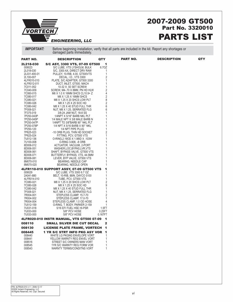
IMPORTANT: Before beginning installation, verify that all parts are included in the kit. Report any shortages or damaged parts immediately.
PARTS LIST®
ENGINEERING, LLC
2L218-030 S/C ASY, 3300 VTS, 07-09 GT500 1009023 S/C LUBE, VTS LYSHOLM, BULK 6.7Oz2L018-030 S/C, 3300 AX, DIRECT DRV RAW 12L031-400-01 PULLEY, 10-RIB, 4.00, GT500VTS 12L100-007 DECAL, I.D., VTS 3300 24LFR010-010 PLATE, S/C ADAPTER, GT500 3300 14LFR012-011 DUCT, INLET, GT500. MACH 17C011-052 10-32 X .50 SET SCREW 17C040-009 SCREW, M4-.70 X 8MM, PN HD HLW 27C060-015 M6 X 1.0 X 16MM SHCS CL10.9+ z 47C080-017 M8 X 1.25 X 16MM SHCS 27C080-021 M8 X 1.25 X 20 SHCS LOW PLT 87C080-026 M8 X 1.25 X 25 SOC HD 27C080-042 M8 X 1.25 X 40 STUD FULL THR 67F008-021 NUT, M8 X 1.25, SERRATED FLG 67F375-019 3/8-24 JAM NUT, 18-8 SS 17P250-043P 1/4NPT X 5/16" BARB NKL PLT 17P250-045P 1/4 MALE NPT X 3/8 MALE BARB N 17P250-047P 1/4NPT TO 3/8"BARB 90° NKL PLT 17P250-078P 1/4 NPT X 5/16 BARB X 90° NKL 17P250-120 1/4 NPT PIPE PLUG 17P625-023 -10 ORB PLUG, THIN HD SOCKET 27P625-024 FITTING, PCV, GT500 VTS 17U012-136 O-RING,2.19OD X 1.98ID X .103W 17U100-008 O-RING 3-908, -8 ORB 18D006-012 ACTUATOR, VACUUM, 2-PORT 18D006-051 WASHER,LOC,BYPAS,LVR,VTS 18D006-061 SHAFT, BYPASS VALVE, GT500 VTS 18D006-071 BUTTERFLY, BYPASS, VTS, 44.5MM 18D006-081 LEVER, BYP VALVE, GT500 VTS 18M070-010 BEARING, NEEDLE CAP 18M070-020 BEARING, NEEDLE OPEN 1
4LFR110-010 SUPPORT ASSY, 07-09 GT500 VTS 1009029 S/C LUBE, VTS 3300 6.7 Oz 12A041-880 BELT, 10-RIB, 88IN, DAYCO 5100 14LFR014-010 TUBE, PCV, GT500 VTS 17C080-021 M8 X 1.25 X 20 SHCS LOW PLT 27C080-026 M8 X 1.25 X 25 SOC HD 97C080-042 M8 X 1.25 X 40 STUD FULL THR 17F008-021 NUT, M8 X 1.25, SERRATED FLG 17R004-001 STEPLESS CLAMP, 15.7-70 27R004-002 STEPLESS CLAMP, 17.0-70 17R004-004 STEPLESS CLAMP, 1.0 OD HOSE 47U012-159 O-RING, T. BODY, PARKER 2-159 17U031-018 5/16 EFI FUEL HSE HI-PSR 1.5FT7U033-000 5/8" PCV HOSE 0.25FT7U033-000 5/8" PCV HOSE 0.167FT
4LFR020-010 INSTR MANUAL, VTS GT500 07-09 1008110 SMALL SILVER DIE CUT DECAL 2008130 LICENSE PLATE FRAME, VORTECH 1008445 1 YR S/C STRT INFO PKG ASY VOR 1
008440 WHITE LG PKGNG ENVELOPE VORT 1008441 YELLOW WARNTY REG ENVEL VORT 1008516 STREET S/C OWNERS MAN VORT 1008545 1YR S/C WARNTY REG FORM VOR 1008543 WARNTY TERMS/CONDITNS VORT 1
PART NO. DESCRIPTION QTY PART NO. DESCRIPTION QTY
P/N: 4LFR020-010 v1.1, 2009-12-17 ©2009 Vortech Engineering, LLC
All Rights Reserved, Intl. Copr. Secured1
A. Disconnect the negative battery terminal.
B. Remove the strut tower brace and set aside. The brace will no longer fit after VTS super-charger installation. Retighten the mounting nuts in their original positions on the strut towers.
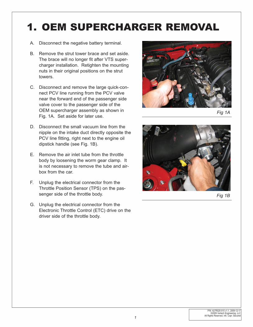
C. Disconnect and remove the large quick-con-nect PCV line running from the PCV valve near the forward end of the passenger side valve cover to the passenger side of the OEM supercharger assembly as shown in Fig. 1A. Set aside for later use.
D. Disconnect the small vacuum line from the nipple on the intake duct directly opposite the PCV line fitting, right next to the engine oil dipstick handle (see Fig. 1B).
E. Remove the air inlet tube from the throttle body by loosening the worm gear clamp. It is not necessary to remove the tube and air-box from the car.
F. Unplug the electrical connector from the Throttle Position Sensor (TPS) on the pas-senger side of the throttle body.
G. Unplug the electrical connector from the Electronic Throttle Control (ETC) drive on the driver side of the throttle body.
1. OEM SUPERCHARGER REMOVAL
Fig 1A
Fig 1B
P/N: 4LFR020-010 v1.1, 2009-12-17©2009 Vortech Engineering, LLCAll Rights Reserved, Intl. Copr. Secured 2
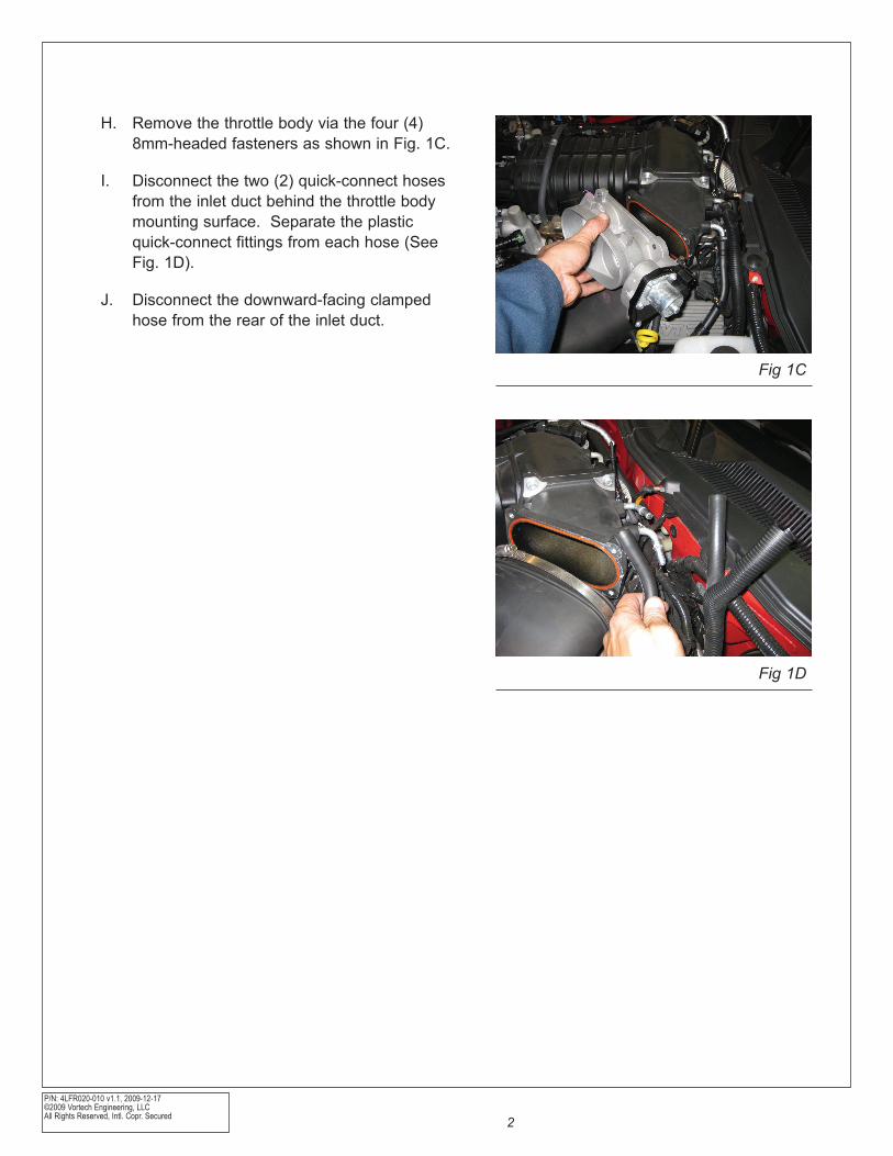
H. Remove the throttle body via the four (4) 8mm-headed fasteners as shown in Fig. 1C.
I. Disconnect the two (2) quick-connect hoses from the inlet duct behind the throttle body mounting surface. Separate the plastic quick-connect fittings from each hose (See Fig. 1D).
J. Disconnect the downward-facing clamped hose from the rear of the inlet duct.
Fig 1C
Fig 1D
P/N: 4LFR020-010 v1.1, 2009-12-17 ©2009 Vortech Engineering, LLC
All Rights Reserved, Intl. Copr. Secured3
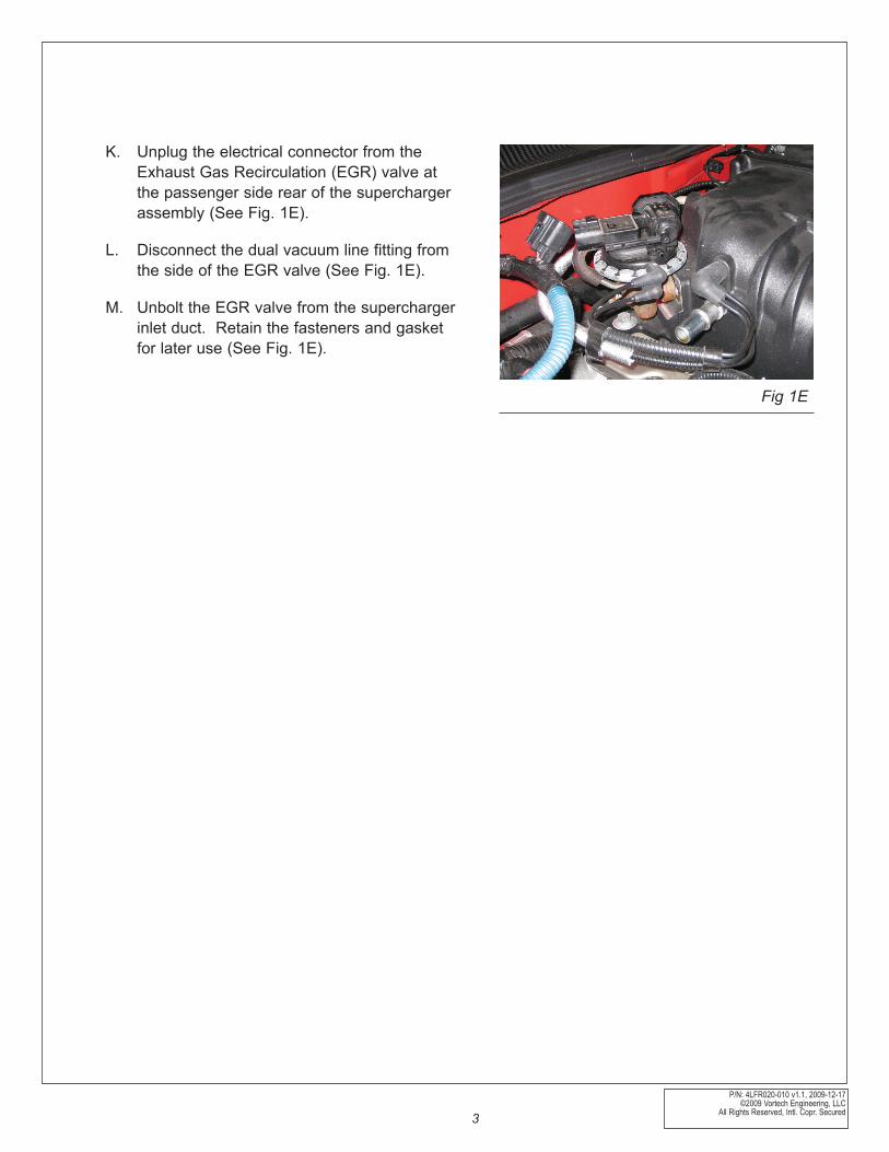
K. Unplug the electrical connector from the Exhaust Gas Recirculation (EGR) valve at the passenger side rear of the supercharger assembly (See Fig. 1E).
L. Disconnect the dual vacuum line fitting from the side of the EGR valve (See Fig. 1E).
M. Unbolt the EGR valve from the supercharger inlet duct. Retain the fasteners and gasket for later use (See Fig. 1E).
Fig 1E
P/N: 4LFR020-010 v1.1, 2009-12-17©2009 Vortech Engineering, LLCAll Rights Reserved, Intl. Copr. Secured 4
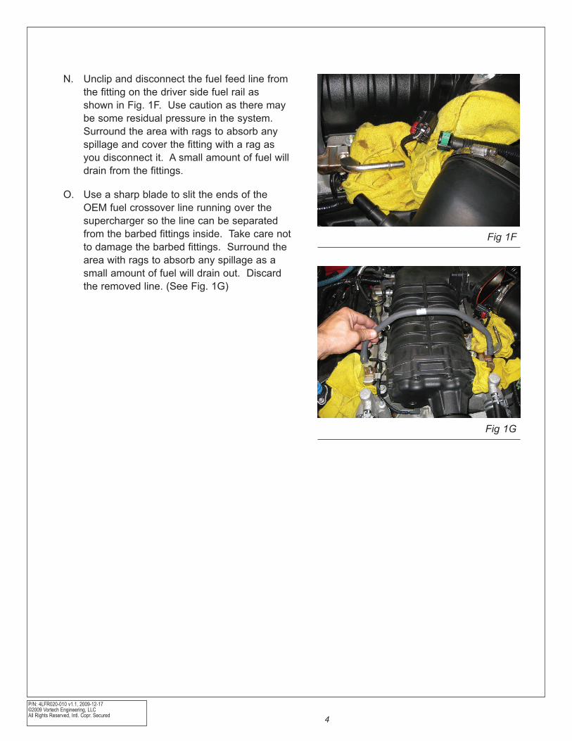
N. Unclip and disconnect the fuel feed line from the fitting on the driver side fuel rail as shown in Fig. 1F. Use caution as there may be some residual pressure in the system. Surround the area with rags to absorb any spillage and cover the fitting with a rag as you disconnect it. A small amount of fuel will drain from the fittings.
O. Use a sharp blade to slit the ends of the OEM fuel crossover line running over the supercharger so the line can be separated from the barbed fittings inside. Take care not to damage the barbed fittings. Surround the area with rags to absorb any spillage as a small amount of fuel will drain out. Discard the removed line. (See Fig. 1G)
Fig 1F
Fig 1G
P/N: 4LFR020-010 v1.1, 2009-12-17 ©2009 Vortech Engineering, LLC
All Rights Reserved, Intl. Copr. Secured5
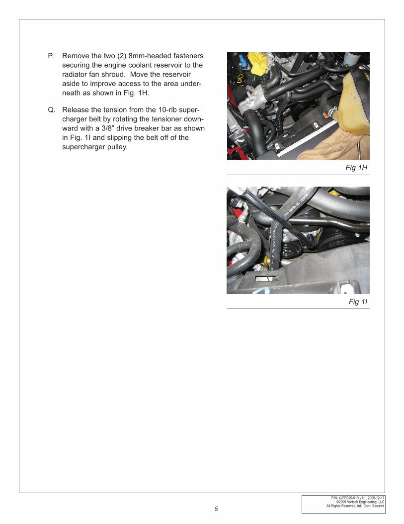
P. Remove the two (2) 8mm-headed fasteners securing the engine coolant reservoir to the radiator fan shroud. Move the reservoir aside to improve access to the area under-neath as shown in Fig. 1H.
Q. Release the tension from the 10-rib super-charger belt by rotating the tensioner down-ward with a 3/8” drive breaker bar as shown in Fig. 1I and slipping the belt off of the supercharger pulley.
Fig 1H
Fig 1I
P/N: 4LFR020-010 v1.1, 2009-12-17©2009 Vortech Engineering, LLCAll Rights Reserved, Intl. Copr. Secured 6
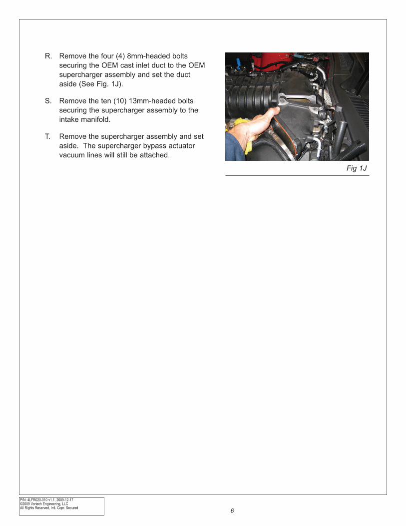
R. Remove the four (4) 8mm-headed bolts securing the OEM cast inlet duct to the OEM supercharger assembly and set the duct aside (See Fig. 1J).
S. Remove the ten (10) 13mm-headed bolts securing the supercharger assembly to the intake manifold.
T. Remove the supercharger assembly and set aside. The supercharger bypass actuator vacuum lines will still be attached.
Fig 1J
P/N: 4LFR020-010 v1.1, 2009-12-17 ©2009 Vortech Engineering, LLC
All Rights Reserved, Intl. Copr. Secured7
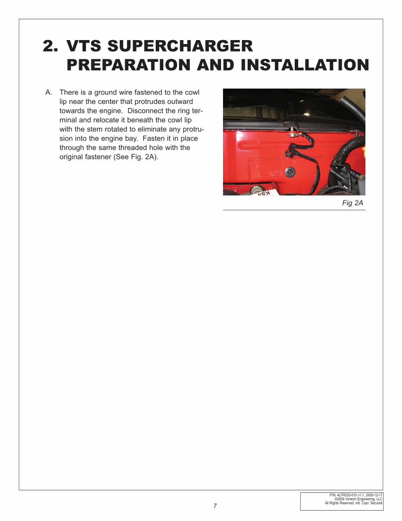
A. There is a ground wire fastened to the cowl lip near the center that protrudes outward towards the engine. Disconnect the ring ter-minal and relocate it beneath the cowl lip with the stem rotated to eliminate any protru-sion into the engine bay. Fasten it in place through the same threaded hole with the original fastener (See Fig. 2A).
Fig 2A
2. VTS SUPERCHARGER PREPARATION AND INSTALLATION
P/N: 4LFR020-010 v1.1, 2009-12-17©2009 Vortech Engineering, LLCAll Rights Reserved, Intl. Copr. Secured 8
B. There is a bracket at the passenger side rear of the engine that secures a large wiring har-ness. Remove the two (2) 8mm-headed fas-teners securing the bracket and set the bracket aside. It will not be reused.
C. Just toward the passenger side from the pre-viously removed wiring harness bracket the same harness is secured with a plastic tab that presses into a hole. Free the harness from this location.
D. Release the tension from the 6-rib accessory drive belt by rotating the tensioner (located between the alternator and the crankshaft) clockwise with a 15mm wrench and slipping the belt off of the water pump pulley. Remove the 6-rib belt from the crankshaft pulley in preparation for removal of the 10-rib supercharger belt. Note: there is a belt rout-ing diagram in your Shelby GT500 Owner’s Manual Supplement.
E. Remove the 15mm-headed bolt securing the 10-rib belt tensioner assembly (located above the A/C compressor) and remove the tensioner from the car. This is necessary for removal of the 10-rib belt itself.
F. Remove the 10-rib belt itself, making note of how it routes over the tensioner. The belt will not be reused. Note: there is a belt rout-ing diagram in your Shelby GT500 Owner’s Manual Supplement.
P/N: 4LFR020-010 v1.1, 2009-12-17 ©2009 Vortech Engineering, LLC
All Rights Reserved, Intl. Copr. Secured9
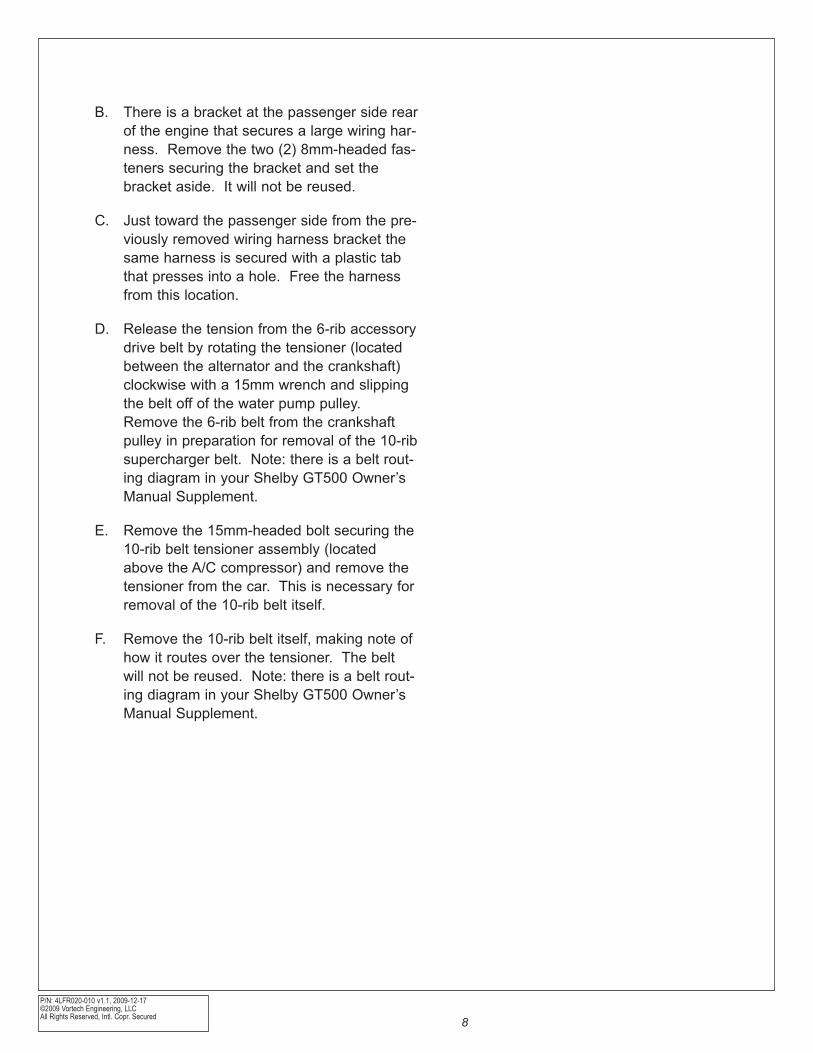
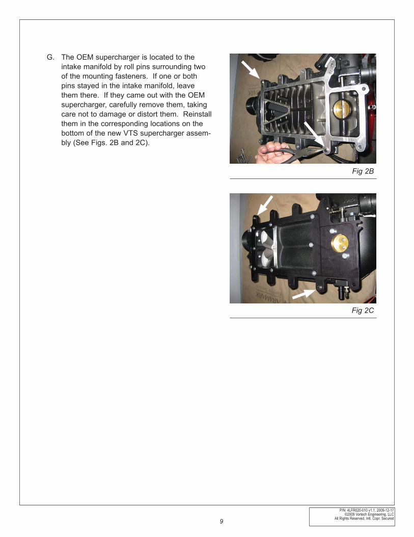
G. The OEM supercharger is located to the intake manifold by roll pins surrounding two of the mounting fasteners. If one or both pins stayed in the intake manifold, leave them there. If they came out with the OEM supercharger, carefully remove them, taking care not to damage or distort them. Reinstall them in the corresponding locations on the bottom of the new VTS supercharger assem-bly (See Figs. 2B and 2C).
Fig 2B
Fig 2C
P/N: 4LFR020-010 v1.1, 2009-12-17©2009 Vortech Engineering, LLCAll Rights Reserved, Intl. Copr. Secured 10
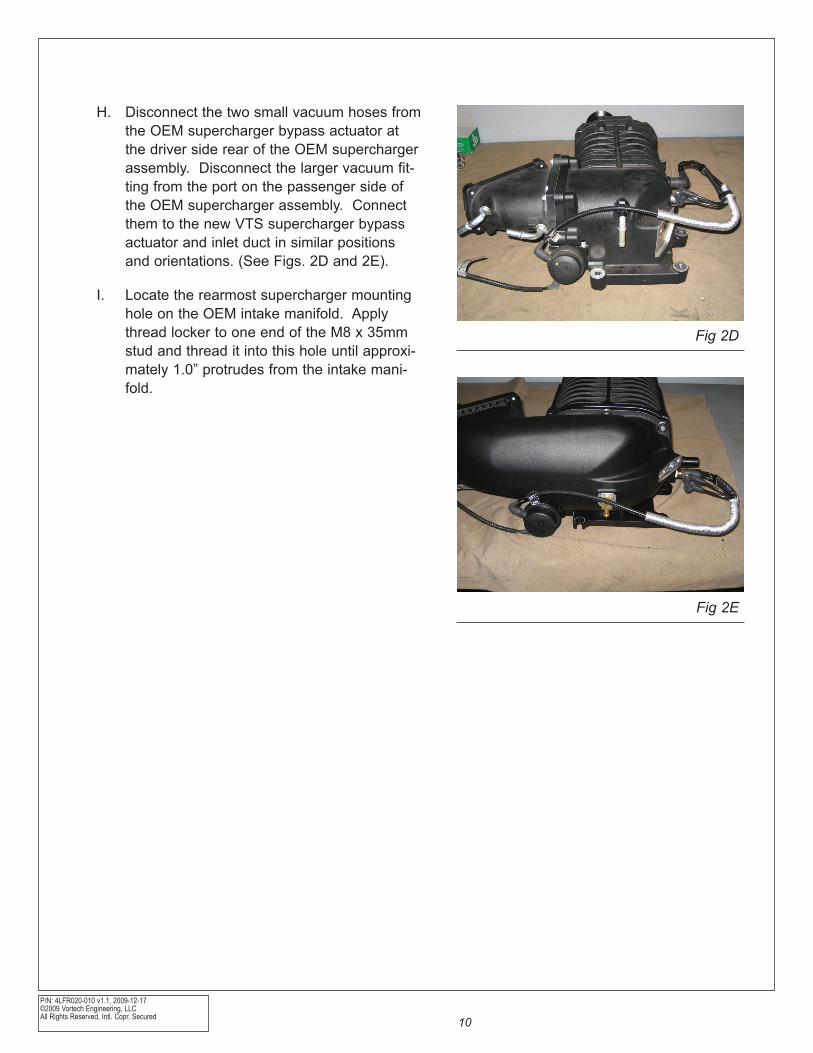
H. Disconnect the two small vacuum hoses from the OEM supercharger bypass actuator at the driver side rear of the OEM supercharger assembly. Disconnect the larger vacuum fit-ting from the port on the passenger side of the OEM supercharger assembly. Connect them to the new VTS supercharger bypass actuator and inlet duct in similar positions and orientations. (See Figs. 2D and 2E).
I. Locate the rearmost supercharger mounting hole on the OEM intake manifold. Apply thread locker to one end of the M8 x 35mm stud and thread it into this hole until approxi-mately 1.0” protrudes from the intake mani-fold.
Fig 2D
Fig 2E
P/N: 4LFR020-010 v1.1, 2009-12-17 ©2009 Vortech Engineering, LLC
All Rights Reserved, Intl. Copr. Secured11
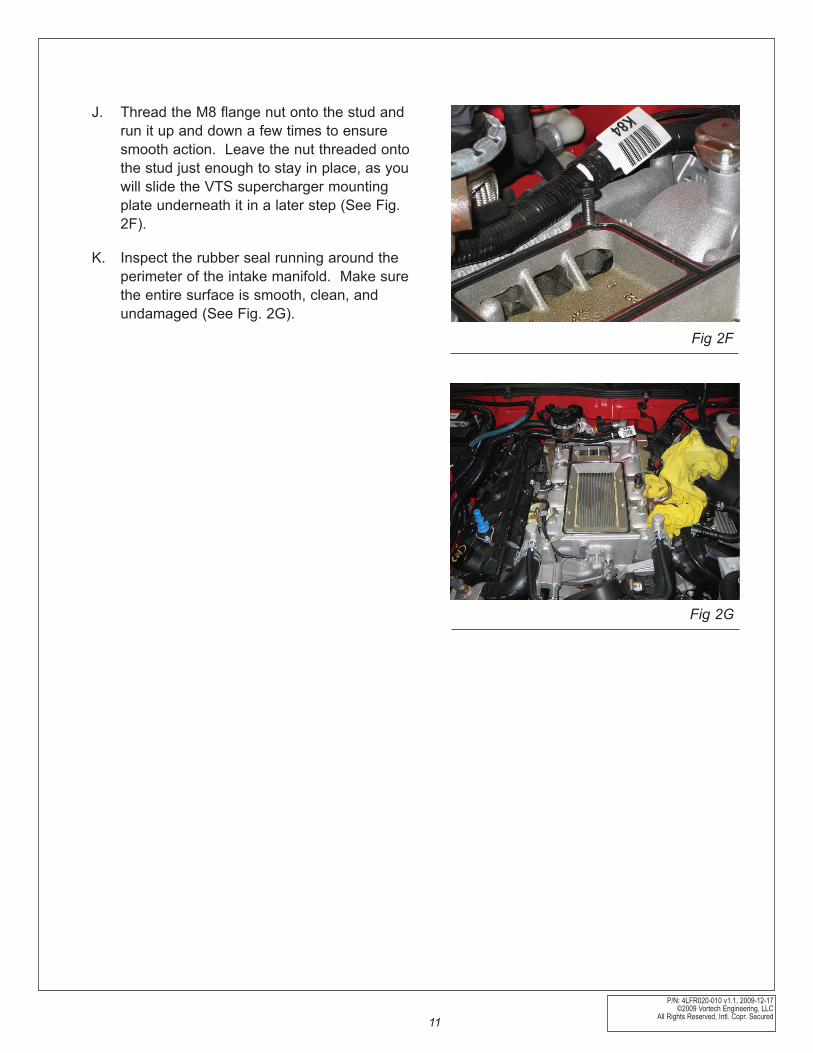
J. Thread the M8 flange nut onto the stud and run it up and down a few times to ensure smooth action. Leave the nut threaded onto the stud just enough to stay in place, as you will slide the VTS supercharger mounting plate underneath it in a later step (See Fig. 2F).
K. Inspect the rubber seal running around the perimeter of the intake manifold. Make sure the entire surface is smooth, clean, and undamaged (See Fig. 2G).
Fig 2F
Fig 2G
P/N: 4LFR020-010 v1.1, 2009-12-17©2009 Vortech Engineering, LLCAll Rights Reserved, Intl. Copr. Secured 12
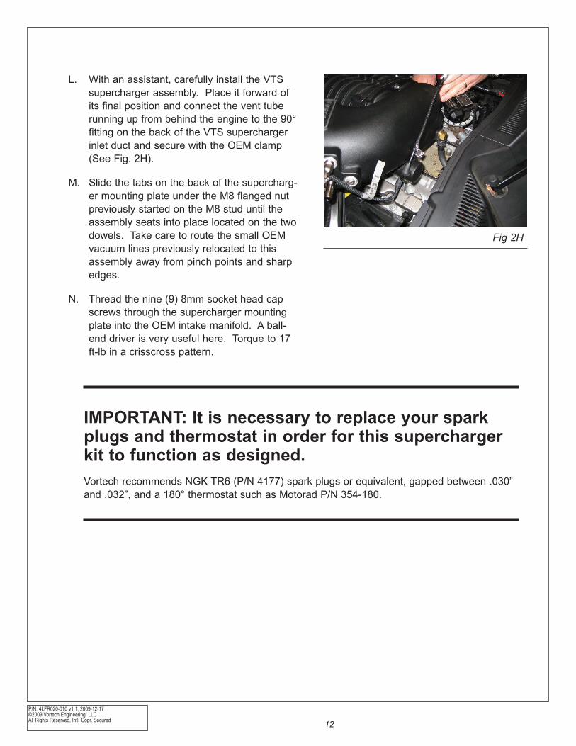
L. With an assistant, carefully install the VTS supercharger assembly. Place it forward of its final position and connect the vent tube running up from behind the engine to the 90° fitting on the back of the VTS supercharger inlet duct and secure with the OEM clamp (See Fig. 2H).
M. Slide the tabs on the back of the supercharg-er mounting plate under the M8 flanged nut previously started on the M8 stud until the assembly seats into place located on the two dowels. Take care to route the small OEM vacuum lines previously relocated to this assembly away from pinch points and sharp edges.
N. Thread the nine (9) 8mm socket head cap screws through the supercharger mounting plate into the OEM intake manifold. A ball-end driver is very useful here. Torque to 17 ft-lb in a crisscross pattern.
Fig 2H
IMPORTANT: It is necessary to replace your spark plugs and thermostat in order for this supercharger kit to function as designed.Vortech recommends NGK TR6 (P/N 4177) spark plugs or equivalent, gapped between .030” and .032”, and a 180° thermostat such as Motorad P/N 354-180.
P/N: 4LFR020-010 v1.1, 2009-12-17 ©2009 Vortech Engineering, LLC
All Rights Reserved, Intl. Copr. Secured13
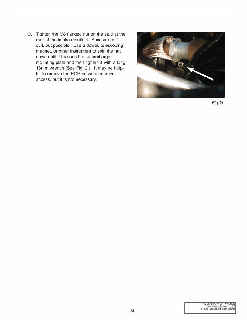
O. Tighten the M8 flanged nut on the stud at the rear of the intake manifold. Access is diffi-cult, but possible. Use a dowel, telescoping magnet, or other instrument to spin the nut down until it touches the supercharger mounting plate and then tighten it with a long 13mm wrench (See Fig. 2I). It may be help-ful to remove the EGR valve to improve access, but it is not necessary.
Fig 2I
P/N: 4LFR020-010 v1.1, 2009-12-17©2009 Vortech Engineering, LLCAll Rights Reserved, Intl. Copr. Secured 14
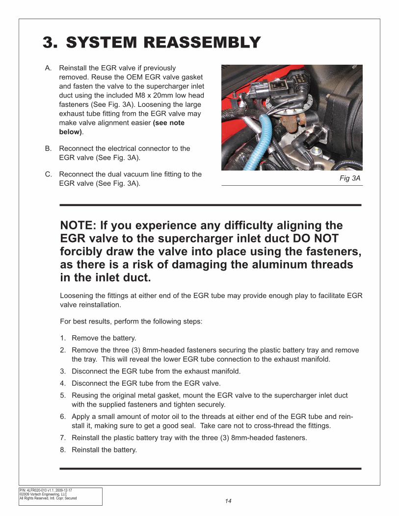
A. Reinstall the EGR valve if previously removed. Reuse the OEM EGR valve gas ket and fasten the valve to the supercharger inlet duct using the included M8 x 20mm low head fasteners (See Fig. 3A). Loosening the large exhaust tube fitting from the EGR valve may make valve alignment easier (see note below).
B. Reconnect the electrical connector to the EGR valve (See Fig. 3A).
C. Reconnect the dual vacuum line fitting to the EGR valve (See Fig. 3A).
Fig 3A
3. SYSTEM REASSEMBLY
NOTE: If you experience any difficulty aligning the EGR valve to the supercharger inlet duct DO NOT forcibly draw the valve into place using the fasteners, as there is a risk of damaging the aluminum threads in the inlet duct.Loosening the fittings at either end of the EGR tube may provide enough play to facilitate EGR valve reinstallation.
For best results, perform the following steps:
1. Remove the battery.
2. Remove the three (3) 8mm-headed fasteners securing the plastic battery tray and remove the tray. This will reveal the lower EGR tube connection to the exhaust manifold.
3. Disconnect the EGR tube from the exhaust manifold.
4. Disconnect the EGR tube from the EGR valve.
5. Reusing the original metal gasket, mount the EGR valve to the supercharger inlet duct with the supplied fasteners and tighten securely.
6. Apply a small amount of motor oil to the threads at either end of the EGR tube and rein-stall it, making sure to get a good seal. Take care not to cross-thread the fittings.
7. Reinstall the plastic battery tray with the three (3) 8mm-headed fasteners.
8. Reinstall the battery.
P/N: 4LFR020-010 v1.1, 2009-12-17 ©2009 Vortech Engineering, LLC
All Rights Reserved, Intl. Copr. Secured15
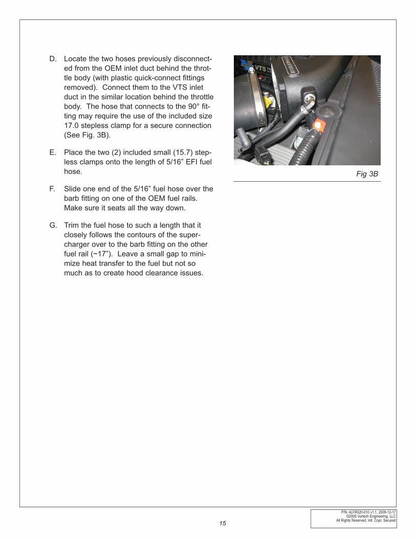
D. Locate the two hoses previously disconnect-ed from the OEM inlet duct behind the throt-tle body (with plastic quick-connect fittings removed). Connect them to the VTS inlet duct in the similar location behind the throttle body. The hose that connects to the 90° fit-ting may require the use of the included size 17.0 stepless clamp for a secure connection (See Fig. 3B).
E. Place the two (2) included small (15.7) step-less clamps onto the length of 5/16” EFI fuel hose.
F. Slide one end of the 5/16” fuel hose over the barb fitting on one of the OEM fuel rails. Make sure it seats all the way down.
G. Trim the fuel hose to such a length that it closely follows the contours of the super-charger over to the barb fitting on the other fuel rail (~17”). Leave a small gap to mini-mize heat transfer to the fuel but not so much as to create hood clearance issues.
Fig 3B
P/N: 4LFR020-010 v1.1, 2009-12-17©2009 Vortech Engineering, LLCAll Rights Reserved, Intl. Copr. Secured 16
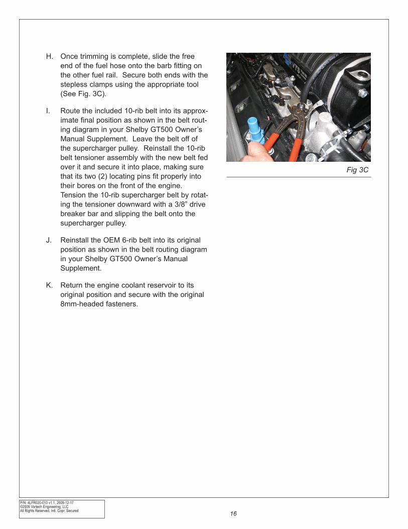
H. Once trimming is complete, slide the free end of the fuel hose onto the barb fitting on the other fuel rail. Secure both ends with the stepless clamps using the appropriate tool (See Fig. 3C).
I. Route the included 10-rib belt into its approx-imate final position as shown in the belt rout-ing diagram in your Shelby GT500 Owner’s Manual Supplement. Leave the belt off of the supercharger pulley. Reinstall the 10-rib belt tensioner assembly with the new belt fed over it and secure it into place, making sure that its two (2) locating pins fit properly into their bores on the front of the engine. Tension the 10-rib supercharger belt by rotat-ing the tensioner downward with a 3/8” drive breaker bar and slipping the belt onto the supercharger pulley.
J. Reinstall the OEM 6-rib belt into its original position as shown in the belt routing diagram in your Shelby GT500 Owner’s Manual Supplement.
K. Return the engine coolant reservoir to its original position and secure with the original 8mm-headed fasteners.
Fig 3C
P/N: 4LFR020-010 v1.1, 2009-12-17 ©2009 Vortech Engineering, LLC
All Rights Reserved, Intl. Copr. Secured17
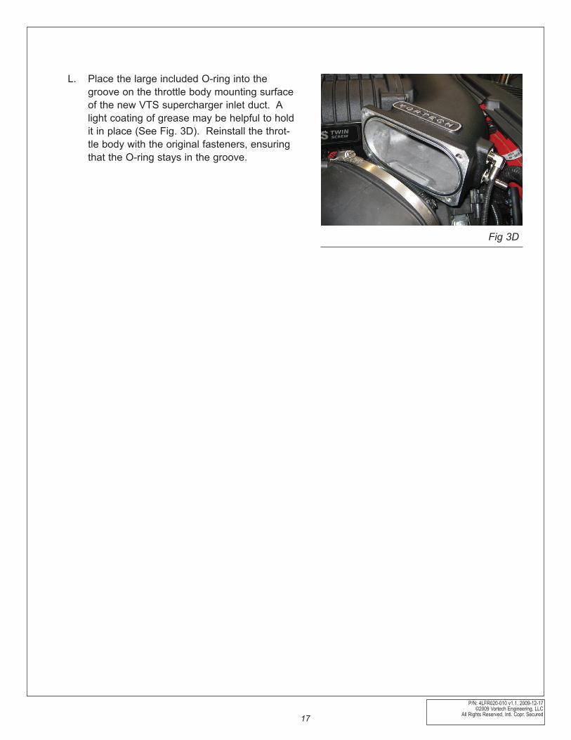
L. Place the large included O-ring into the groove on the throttle body mounting surface of the new VTS supercharger inlet duct. A light coating of grease may be helpful to hold it in place (See Fig. 3D). Reinstall the throt-tle body with the original fasteners, ensuring that the O-ring stays in the groove.
Fig 3D
P/N: 4LFR020-010 v1.1, 2009-12-17©2009 Vortech Engineering, LLCAll Rights Reserved, Intl. Copr. Secured 18
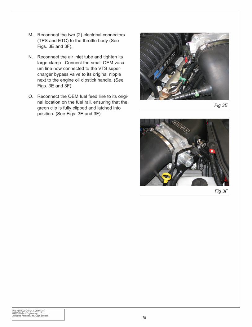
M. Reconnect the two (2) electrical connectors (TPS and ETC) to the throttle body (See Figs. 3E and 3F).
N. Reconnect the air inlet tube and tighten its large clamp. Connect the small OEM vacu-um line now connected to the VTS super-charger bypass valve to its original nipple next to the engine oil dipstick handle. (See Figs. 3E and 3F).
O. Reconnect the OEM fuel feed line to its origi-nal location on the fuel rail, ensuring that the green clip is fully clipped and latched into position. (See Figs. 3E and 3F).
Fig 3E
Fig 3F
P/N: 4LFR020-010 v1.1, 2009-12-17 ©2009 Vortech Engineering, LLC
All Rights Reserved, Intl. Copr. Secured19
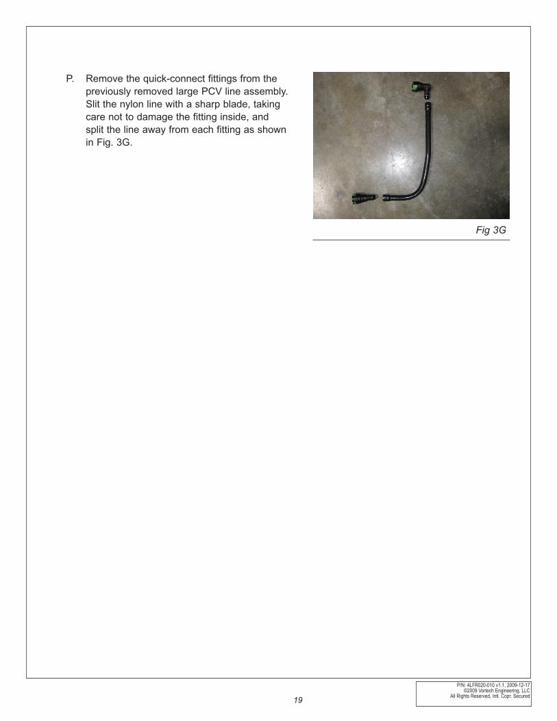
P. Remove the quick-connect fittings from the previously removed large PCV line assembly. Slit the nylon line with a sharp blade, taking care not to damage the fitting inside, and split the line away from each fitting as shown in Fig. 3G.
Fig 3G
P/N: 4LFR020-010 v1.1, 2009-12-17©2009 Vortech Engineering, LLCAll Rights Reserved, Intl. Copr. Secured 20
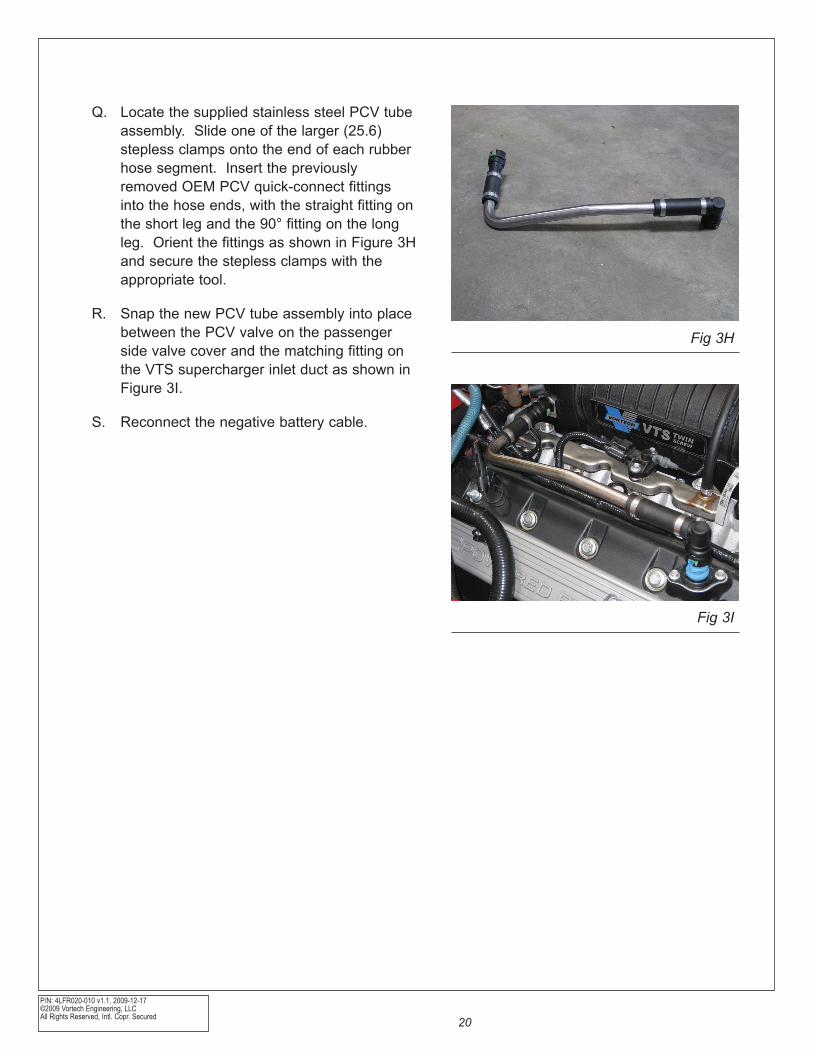
Q. Locate the supplied stainless steel PCV tube assembly. Slide one of the larger (25.6) stepless clamps onto the end of each rubber hose segment. Insert the previously removed OEM PCV quick-connect fittings into the hose ends, with the straight fitting on the short leg and the 90° fitting on the long leg. Orient the fittings as shown in Figure 3H and secure the stepless clamps with the appropriate tool.
R. Snap the new PCV tube assembly into place between the PCV valve on the passenger side valve cover and the matching fitting on the VTS supercharger inlet duct as shown in Figure 3I.
S. Reconnect the negative battery cable.
Fig 3H
Fig 3I

P/N: 4LFR020-010 v1.1, 2009-12-17 ©2009 Vortech Engineering, LLC
All Rights Reserved, Intl. Copr. Secured21

P/N: 4LFR020-010 v1.1, 2009-12-17©2009 Vortech Engineering, LLCAll Rights Reserved, Intl. Copr. Secured 22
1650 PACIFIC AVENUE • CHANNEL ISLANDS, CA 93033-9901 • (805) 247-0226FAX (805) 247-0669 • www.vortechsuperchargers.com • M-F 8:00 AM - 4:30 PM PST
ENGINEERING, LLC
®


![Administering Cisco VTS · admin@VTS-A:~$ sudo su [sudo] password for admin: Step2 SourcetheVTSenvironment. root@VTS-A:# source /etc/profile.d/ncs.sh Step3 VerifyVTSstatus. root@VTS-A:#](https://img.dokumen.tips/doc/110x75/5ec8e3d704a90406890d6ec6/administering-cisco-vts-adminvts-a-sudo-su-sudo-password-for-admin-step2.jpg)