Embed Size (px)
Citation preview
GSM CAR SECURITY SYSTEM
MOHD AZWAN BIN RAMLAN
A thesis submitted in fulfilment of the requirements for the award of the Bachelor of
Electrical Engineering (Electronics)
Faculty of Electrical & Electronics Engineering
Universiti Malaysia Pahang
MAY, 2012
ABSTRACT
The development of GSM Car Security System is a solution to all vehicle
owners to increase the security of their vehicle from car theft. This project can alert
the owner by sending SMS messages after detecting an intruder. The owner also can
monitor their car status by sending SMS messages. This project consists of two parts
which are hardware design and software development. For hardware design, the
system is controlled by a microcontroller PIC 18F4550. The detector of limit switch
is used as the input of PIC. Global System for Mobile Communication (GSM) is
preferred in the wireless communication because due to its effectiveness and the use
of Short Message Services (SMS). SMS was used because the increasing use of
mobile phone. For Software development, CCS Compiler for PIC is use to program
the system that enables the function of detecting, identifying, sending SMS and
indication for every possible action.
ABSTRAK
Pembangunan Sistem Keselamatan Kereta berdasarkan GSM adalah
penyelesaian kepada semua pemilik kenderaan untuk meningkatkan keselamatan
kenderaan mereka dari kecurian kereta. Projek ini boleh memberi amaran kepada
pemilik dengan menghantar Sistem Pesanan Ringkas (SMS) selepas mengesan
penceroboh. Pemilik juga boleh memantau status kereta mereka dengan menghantar
SMS. Projek ini terdiri daripada dua bahagian iaitu reka bentuk perkakasan dan
pembangunan perisian. Untuk bahagian reka bentuk perkakasan, sistem dikawal
oleh mikropengawal PIC18F4550. Suis pengesan digunakan sebagai input PIC.
Global System for Mobile (GSM) yang dipilih dalam komunikasi tanpa wayar kerana
disebabkan keberkesanan dan penggunaan SMS. SMS digunakan kerana peningkatan
penggunaan telefon bimbit. Untuk pembangunan perisian, MikroC untuk PIC
digunakan untuk memprogram sistem yang membolehkan fungsi mengesan,
mengenal pasti, menghantar SMS dan petunjuk bagi setiap tindakan yang mungkin.
TABLE OF CONTENTS
DECLARATION OF THESIS STATUS
TITLE
DECLARATION BY SUPERVISOR ii
DECLARATION iii
DEDICATION iv
ACKNOWLEDGEMENT v
ABSTRACT vi
ABSTRAK vii
TABLE OF CONTENT viii
LIST OF FIGURES xii
LIST OF TABLES xv
LIST OF ABBREVIATIONS xvi
LIST OF SYMBOL xvii
LIST OF APPENDICES xviii
CHAPTER PAGE
1. INTRODUCTION
1.1 Introduction 1
1.2 Project Statement 3
1.3 Objective 3
1.4 Scope of Project 3
1.5 Overview of Project 4
1.6 Thesis Outline 4
2. LITERATURE RIVIEW
2.1 Introduction 6
2.2 Short Message Services (SMS) 6
2.3 Global System for Mobile Communication (GSM) 7
2.4 Mobile Station (MS) 8
2.5 AT Command 9
2.6 Microcontroller PIC 18F4550 10
2.6.1 Special Features of Microcontroller 10
2.7 Serial Communication 12
2.8 Related Works 12
2.9 Summary 13
3. ARCHITECTURE OF GSM CAR SECURITY SYSTEM
3.1 Introduction 14
3.2 Flowchart Methodology 15
3.3 System Architecture 17
3.3.1 Microcontroller System Board Module 17
3.3.2 LCD module 19
3.3.3 Sound indicator module 19
3.3.4 Motor module 20
3.3.5 Limit Switch module 21
3.3.6 GSM modem module 21
4. HARDWARE DESIGN
4.1 Introduction 23
4.2 Microcontroller Module 24
4.3 Clock Circuit 26
4.4 Power Supply Circuit 27
4.5 Reset Circuit 28
4.6 Liquid Crystal Display 29
4.7 GSM Modem Module 29
4.7.1 RS232 DB-9 Connector 32
4.8 DC Motor Module 33
4.9 Limit Switch Module 34
4.10 Buzzer Module 35
4.11 Summary 36
5. SOFTWARE DEVELOPMENT
5.1 Introduction 37
5.2 Microcontroller Module Testing 38
5.3 LCD Module Testing 39
5.4 GSM Car Security System Software 40
5.5 Programming Tools 42
5.5.1 CCS Compiler 42
5.5.2 USB PIC Programmer V2009 (UP00B) 44
5.5.3 PICkit 2 v2.55 45
5.5.4 Proteus 46
5.6 Summary 47
6. TESTING AND RESULT
6.1 Testing and Result 48
6.2 PIC18F4550 System Testing 49
6.3 LCD Module Testing 51
6.4 GSM module testing 53
6.5 DC Motor Module testing 58
6.6 GSM Car Security testing 59
6.6 Summary 62
7. CONCLUSION AND RECOMMENDATION
7.1 Conclusion 63
7.2 Recommendation 63
7.3 Cost and Commercialization 64
REFERENCES 65
APPENDICES A 67
1
CHAPTER 1
INTRODUCTION
1.1 Introduction
In recent years, Malaysia faces the uprising of crime rate. The biggest crimes
which are hard to eliminate is car theft. According to the statistic provide by the
General Insurance Association of Malaysia (PIAM), the total numbers for the car
theft that have been reported from the year 2000 to year 2010 is 80,577 [1].
Nowadays, car are produce with security such as steering lock or pedal lock
that use to prevent the car from being invaded and stolen but how far is the efficiency
of using that kind of security? Car thief can easily disarm the security within
minutes. Usually when the owner will realize his car has been breach, the car
probably has already got away or expensive items inside car have been stolen which
increasing their burden and risk. That is when the idea of car security that utilizes
GSM system is conducted to enhanced car security system in Malaysia.
Wireless and remote vehicles are an important technology with many
advantages. Firstly, owner can monitor their status of car wherever there are without
the necessity to go to check their vehicles by their self from time to time. Secondly,
2
the system can monitor the car and inform owner when there is breach hence provide
real-time monitor for owners.
The wireless technology is now widely being used in communication area to
facilitate information transfer and exchange in wireless sensor network. One of its
usages is in promoting remote monitoring car for owners. However, some of
underserved areas in the world do not have the communications infrastructure to be
able to benefit from remote car monitoring systems.
GSM Car Security System is a wireless based security monitoring system.
The aim of the project is to build and develop a system that has an additional feature
of the present security system which is based on GSM. This system is equipped with
limit switch as an input. PIC18F4550 is embedded to control the system operation. In
addition, DC motor is used as an output to control the lock of car door. The GSM
based technology is used in order to transmit and receive information wirelessly
between car and owner.
The system are becoming more significant to developed is when the owner is
far away from the car to hear the alarm of the car. The SMS from the in-car phone
will give immediate alert to the owner to take an instant action or to notify the local
authorities or car immobilizer service to immobilize the car. The present car security
system is not sufficient to prevent auto theft even though the car is equipped with one
of the most expensive system.
Sometimes the alarm does not even attract the attention of most of the public.
With the installation of the new feature of this alarm, the owner will be notified
immediately so the owner will take preventive measure to check his car or save the
precious time by informing the authorities.
3
1.2 Project Statement
This report describes an effort to produce GSM Car Security System. In
current issues in Malaysia, car theft often occurs to vehicles that has no or minimum
security that can lose a lot of property. By using GSM car security system, an early
warning of breach can be faster transceiver to owner.
1.3 Objective
The objective of making GSM Car Security System is to design and build a
system that has an additional feature of the present security system which is based on
GSM. GSM car security system is one tool that can help owner by provide a solution
to avoid car theft in lower cost.
1.4 Scope of Project
In order to achieve the objectives of the project, the scopes of project are
summarized as follow:
1. Doing literature review about the hardware and software used in
developing car security.
2. Develop Microcontroller that can lock/unlock the car door and operate
the alarm systems which connect at several sensors.
3. Develop GSM modem that can communicate both ways.
4
4. Program AT command onto PIC 18F4550 microcontroller to sent
information for GSM modem to send SMS to owner’s phone.
1.5 Overview of Project
This project is concerned with the designing and developing of GSM car
security system which can be used for the commercial project at vehicles. An
advantage of this project is it can reduce car theft and give early warning to owner
when their vehicle is breach. Combination of GSM communication and interfacing
with microcontroller develop using CCS compiler.
Once the vehicles are being breach, the information will be transmitted
wirelessly to the owner of the vehicle. The microcontroller will be used to interface
with the GSM modem in the event of data transmission. The PIC 18f4550 also will
automatically active the GSM modem when the vehicles car door is not close
properly and transmitted to inform the owner through GSM modem. The owner also
can communicate with the GSM modem through owner phone.
1.6 Thesis Outline
This thesis is structured in seven main chapters. The contents of each chapter
are summarized as below:
Chapter 1 consist of the introduction, project statement, objectives, the scope
of project, overview of the project and summary of the content of thesis.
5
Chapter 2 describes the literature review on Short Message Services (SMS),
Global System for Mobile communication (GSM), Mobile Station (MS), AT
command, PIC18F4550, Serial Communication and some literature reviews of
related works.
Chapter 3 is the system architecture of project. It explains the operation of
this project. Block diagram for each module are discussed in this chapter.
Chapter 4 present the hardware design which discusses the detail of hardware
design of each module. The connections of hardware are shown in the circuit
schematic diagram.
Chapter 5 indicates the software development for each module. The flow
chart diagrams are shown in this chapter for the simple explanation.
Chapter 6 present the testing and evaluating results of each module which the
entire integrated modules operation is also discussed in this chapter.
Chapter 7 concludes the outcome of this project and also include the
recommendations on this project for future works to upgrade the system
performance.
6
CHAPTER 2
LITERATURE REVIEW
2.1 Introduction
This chapter elaborates the recent research on the technology and emphasizes
the use of GSM modem in various applications. Explanation will be focused on the
related car security system. Research and findings have been conducted in order to
design and develop GSM Car Security System that will suit the aims and objectives
in this project. All the related research papers and journals will be discussed here.
2.2 Short Message Services (SMS)
According to Ericsson, “Short Message Service: available on digital networks
allowing messages of up to 160 characters to be sent and received via the network
operator's message centre to your mobile phone” [2]
7
This can be simplify that SMS is a transmission of short messages by cellular
phone, fax machine or IP address in two communications. The messages must not
exceed 160 alphanumeric characters and contain no image or graphics. SMS
messages are supported by GSM, TDMA and CDMA based cellular phone networks
currently in use [3]. There are 10 million subscribers of mobile phones in the world
and 97% users know how to use SMS [4].
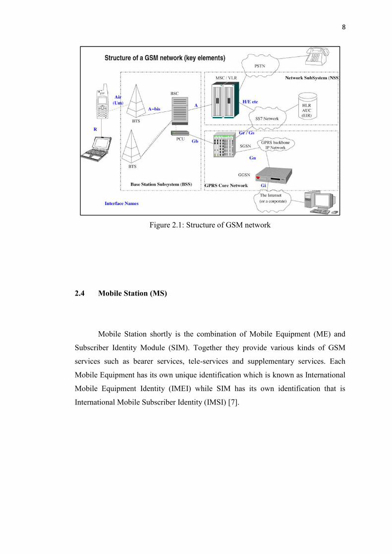
2.3 Global System for Mobile Communication (GSM)
GSM was introduced in the late 1980s where it was define as the European
standards for a new mobile communications system .GSM also known for the
existing of 2G and 2.5G digital cellular systems. Standard digital GSM based cellular
phone services of the 2G era offer voice and low data rates. GSM network are circuit
switched and use a combination of the TDMA (Time Division Multiple Access) and
FDMA (Frequency Division Multiple Access) standard to enable multiple subscriber
bandwidth access at data transfer rates up to 14.4kpbs [5].
A GSM modem is a wireless modem that works with a GSM wireless
network. A wireless modem behaves like a dial-up modem. The main difference
between them is that a dial-up modem sends and receives data through a fixed
telephone line while a wireless modem sends and receives data through radio waves.
Like a GSM mobile phone, a GSM modem requires a SIM card from a wireless
carrier in order to operate [6].
8
Figure 2.1: Structure of GSM network
2.4 Mobile Station (MS)
Mobile Station shortly is the combination of Mobile Equipment (ME) and
Subscriber Identity Module (SIM). Together they provide various kinds of GSM
services such as bearer services, tele-services and supplementary services. Each
Mobile Equipment has its own unique identification which is known as International
Mobile Equipment Identity (IMEI) while SIM has its own identification that is
International Mobile Subscriber Identity (IMSI) [7].
9
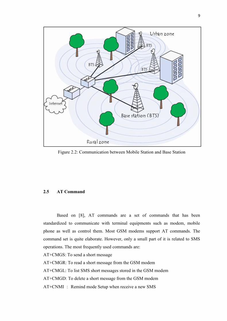
Figure 2.2: Communication between Mobile Station and Base Station
2.5 AT Command
Based on [8], AT commands are a set of commands that has been
standardized to communicate with terminal equipments such as modem, mobile
phone as well as control them. Most GSM modems support AT commands. The
command set is quite elaborate. However, only a small part of it is related to SMS
operations. The most frequently used commands are:
AT+CMGS: To send a short message
AT+CMGR: To read a short message from the GSM modem
AT+CMGL: To list SMS short messages stored in the GSM modem
AT+CMGD: To delete a short message from the GSM modem
AT+CNMI: Remind mode Setup when receive a new SMS
10
As the low-level function interface to the GSM modem, these commands play a
fundamental role in the software developing of the gateway program.
2.6 Microcontroller PIC 18F4550
PIC was acronym for ‘Peripheral Interface Controller’ also known as a
microcontroller. It typically includes:
CPU (Central Processing Unit)
RAM (Random Access Memory)
EPROM/PROM/ROM(Erasable Programmable Read Only Memory)
I/O(Input/output)-serial and parallel
Timers
Interrupt controller
By only including the features specific to the task (control), cost is relatively low.
A typical microcontroller has bit manipulation instructions, easy and direct access to
I/O (input/output), and quick and efficient interrupt processing. Microcontrollers are
“one-chip solution'' which drastically reduces parts count and design costs [9].
2.6.1 Special Features of Microcontroller
The PIC 18F4550 microcontroller is chosen since its easiness to use, high
speed and its low cost compare to other microcontroller. It also low power, high
speed FLASH/EEPROM using CMOS technology. It also has 100,000 write or erase

11
cycle enhanced FLASH program memory and has 1,000,000 write or erase cycle
data EEPROM memory typical. The PIC 18F4550 have features as below [10]:
C Compiler Optimized Architecture with optional extended instruction
set.
Wide Operating Voltage Range (2.0V to 5.5V)
Extended Watchdog Timer (WDT)
Programmable Code Protection
Flash/Data EEPROM retention more than 40 years
Priority levels for interrupts
Single-Supply 5V In-Circuit Serial
Self-Programmable under Software Control
Table below shows the similarities and differences between PIC 18F4550 and
PIC 16F877A [11].
TABLE 2.1: Comparison between PIC 18F4550 and PIC 16F877A
Key Features PIC 18F4550 PIC 16F877A
Pins 40 DIP 40 DIP
I/O Ports A,B,C,D,E A,B,C,D
Operating Frequency DC-48Mhz DC- 20Mhz
Reset (and Delays) POR, BOR,
RESET Instruction,
Stack Full, (PWRT,
OST),
MCLR,
WDT
POR, BOR
(PWRT,OST)
Flash Program Memory 32K 8K
Data memory (bytes) 2048 368
EEPROM Data Memory(bytes) 256 256
Interrupts 20 15
Timers 4 3
Capture/Compare/PWM modules 1 2
12
Serial Communications MSSP, Enhanced
USART
MSSP, USART
10-bit Analog to Digital Module 13 input channels 8 input channels
Analog Comparators 2 2
Instruction Set 75 35
2.7 Serial Communication
Serial port is used in order to transmit and receive data because it allows user
to change the baud rate, data bit, size and parity bits. This serial port communication
such as RS232 at GSM modem is needed to communicate with microcontroller. In
addition, PIC18F4550 is used as microcontroller which is built-in USART support
(RS232). Furthermore, the PIC18F series has a large number of I/O ports which
easier for debugging and other applications [12].
2.8 Related Works
Group of lecturer [13] has created a design that controls other electrical
equipments by using SMS as the ways to switch on or off the devices. This circuit
can control the devices by sending the specific SMS through mobile phone. The
circuit is very simple where it uses relay as switch and AT commands as modem
command that can understand the data send from PIC microcontroller. This design
modified the mobile phone to work as a transmitter part that can send SMS when the
switch is triggered. Ericsson T10 mobile phone is used in this circuit where terminal
of communication at mobile phone operates at 5V control by AT9052313.
13
Noraishah bt. Mohd Tahir [14] has designed a security system used for
motorcycle. The system used the limit switch as the sensor of the system to trigger
the circuit. The limit switch is placed at double stand of the motorcycle where it
functions as sensor to indicate any movement at motorcycle while the system in on
mode. When intruders wants to move the motorcycle, it’s automatically trigger the
microcontroller circuit to send the notification SMS to the owners to follow up
actions.
From this two related works, it is stated that both of this related works are
using GSM modem or modified hand phone to send SMS to owner to inform when
there is intruder which is similar to the objective of this project. Both work also use
AT command to interface with microcontroller. The differences are that both work
using difference microcontroller and different application.
2.9 Summary
The main components of the project are described in this chapter. The first
function in the system is that it can detect unknown person when the user activated
this system. PIC microcontroller will read the data when the limit switch is
activated. Then the GSM modem gets data from PIC Microcontroller to send SMS to
owner hand phone.
To communicate between GSM modem and hand phone, AT command is
apply to this project. It is because, the GSM modem just can only understand AT
command declaration. From this, it can communicate with hand phone, computer and
PIC microcontroller.
To accomplish this project, the whole component must work effectively. The
GSM modem acts as medium to receive the instructions from microcontroller. C
programming is used for PIC board application to develop program.
14
CHAPTER 3
ARCHITECTURE OF GSM CAR SECURITY SYSTEM
3.1 Introduction
This chapter elaborates on the system architecture of GSM Car Security
System. Figure 3.1 shows the block diagram of GSM Car Security System where the
microcontroller is used to interface with the GSM modem by using serial
communication (RS232) in the event of data transmission. The microcontroller will
automatically activate the GSM modem when the cars doors are in unusual
conditions such as lock/unlock without the present of car owner or the door is not
close properly. It will send message to the car owner/authorities. The message
contains the detail of status of the car. The car owner/authorities can send or reply
message to microcontroller through the GSM modem.

15
Figure 3.1: Block diagram of GSM car security system
3.2 Flowchart Methodology
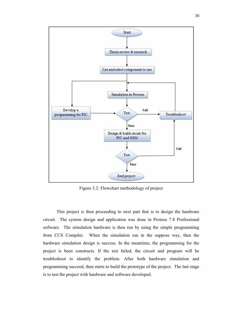
Figure 3.2 below show the flowchart of methodology to conduct the project.
First to start off are by reviewing several related literatures base on journals, relevant
papers and publications. After that, type of components that will be use in the project
such as PIC microcontroller, GSM and other components are listed and selected.
16
Figure 3.2: Flowchart methodology of project
This project is then proceeding to next part that is to design the hardware
circuit. The system design and application was done in Proteus 7.8 Professional
software. The simulation hardware is then run by using the simple programming
from CCS Compiler. When the simulation run in the suppose way, then the
hardware simulation design is success. In the meantime, the programming for the
project is been constructs. If the test failed, the circuit and program will be
troubleshoot to identify the problem. After both hardware simulation and
programming succeed, then starts to build the prototype of the project. The last stage
is to test the project with hardware and software developed.
17
3.3 System Architecture
The GSM car security system consists of following hardware module:
Microcontroller module
LCD module
Buzzer module
Motor module
Limit switch module
GSM modem module
3.3.1 Microcontroller System Board Module
Microcontroller is a brain of the system which is to control all the operations
of system. Microcontroller 18F series is been implement in this project due to its
high performance. Microcontroller is designed into two packages that are Dial-In-
Line Package (DIP) and Plastic Lead Chip Carrier (PLCC). There are various form
PIC version available with different size and features. However, PIC 18F4550 is
chosen in this project.