Embed Size (px)
Citation preview
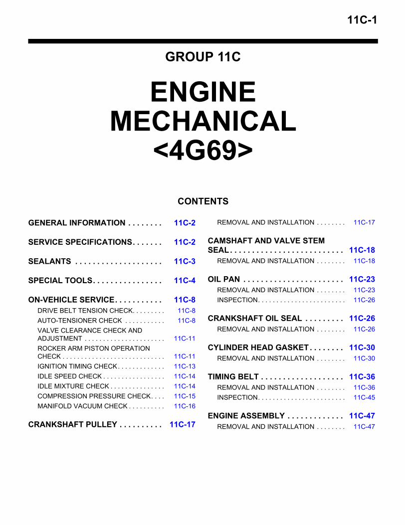
11C-1
GROUP 11C
ENGINE MECHANICAL
<4G69>CONTENTS
GENERAL INFORMATION . . . . . . . . 11C-2
SERVICE SPECIFICATIONS. . . . . . . 11C-2
SEALANTS . . . . . . . . . . . . . . . . . . . . 11C-3
SPECIAL TOOLS. . . . . . . . . . . . . . . . 11C-4
ON-VEHICLE SERVICE. . . . . . . . . . . 11C-8DRIVE BELT TENSION CHECK. . . . . . . . . 11C-8AUTO-TENSIONER CHECK . . . . . . . . . . . 11C-8VALVE CLEARANCE CHECK AND ADJUSTMENT . . . . . . . . . . . . . . . . . . . . . . 11C-11ROCKER ARM PISTON OPERATION CHECK . . . . . . . . . . . . . . . . . . . . . . . . . . . . 11C-11IGNITION TIMING CHECK. . . . . . . . . . . . . 11C-13IDLE SPEED CHECK . . . . . . . . . . . . . . . . . 11C-14IDLE MIXTURE CHECK . . . . . . . . . . . . . . . 11C-14COMPRESSION PRESSURE CHECK. . . . 11C-15MANIFOLD VACUUM CHECK . . . . . . . . . . 11C-16
CRANKSHAFT PULLEY . . . . . . . . . . 11C-17
REMOVAL AND INSTALLATION . . . . . . . . 11C-17
CAMSHAFT AND VALVE STEM SEAL. . . . . . . . . . . . . . . . . . . . . . . . . . 11C-18
REMOVAL AND INSTALLATION . . . . . . . . 11C-18
OIL PAN . . . . . . . . . . . . . . . . . . . . . . . 11C-23REMOVAL AND INSTALLATION . . . . . . . . 11C-23INSPECTION. . . . . . . . . . . . . . . . . . . . . . . . 11C-26
CRANKSHAFT OIL SEAL . . . . . . . . . 11C-26REMOVAL AND INSTALLATION . . . . . . . . 11C-26
CYLINDER HEAD GASKET . . . . . . . . 11C-30REMOVAL AND INSTALLATION . . . . . . . . 11C-30
TIMING BELT . . . . . . . . . . . . . . . . . . . 11C-36REMOVAL AND INSTALLATION . . . . . . . . 11C-36INSPECTION. . . . . . . . . . . . . . . . . . . . . . . . 11C-45
ENGINE ASSEMBLY . . . . . . . . . . . . . 11C-47REMOVAL AND INSTALLATION . . . . . . . . 11C-47

GENERAL INFORMATIONENGINE MECHANICAL <4G69>11C-2
GENERAL INFORMATIONM1111000100505
SERVICE SPECIFICATIONSM1112000300278
Item 4G69Total displacement mL 2,378Bore × Stroke mm 87 × 100Compression ratio 9.5Compression chamber PentroofCamshaft arrangement SOHCNumber of valve Intake 8
Exhaust 8Valve timing Intake valve Open (BTDC) 10° <low speed cam A>
12° <low speed cam B>24° <High speed cam>
Closes (ABDC) 42° <low speed cam A>44° <low speed cam B>68° <High speed cam>
Exhaust valve Open (BTDC) 58°Closes (ABDC) 18°
Fuel system Electronically controlled multipoint fuel injectionRocker arm Roller type
Item Standard value LimitDrive belt tension Vibration frequency Hz
(Reference)A/C compressor type: MSC90CA
113 − 145 −
A/C compressor type: MSC105CA
120 − 154 −
Tension N (Reference) 340 − 555 −Valve clearance (at hot) mm Intake valve 0.20 −
Exhaust valve 0.30 −Basic ignition timing 5° BTDC ± 3° −Ignition timing Approximately
10° BTDC−
Idle speed r/min M/T 680 ± 100 −A/T 750 ± 100 −
CO contents % 0.5 or less −HC contents ppm 100 or less −Compression pressure kPa-r/min 1,560 − 200 1,130 − 200Compression pressure difference of all cylinders kPa − Maximum 98
SEALANTSENGINE MECHANICAL <4G69> 11C-3
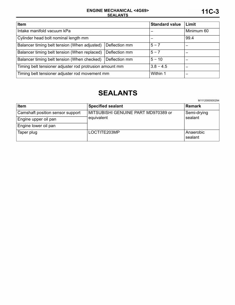
SEALANTSM1112000500294
Intake manifold vacuum kPa − Minimum 60Cylinder head bolt nominal length mm − 99.4Balancer timing belt tension (When adjusted) Deflection mm 5 − 7 −Balancer timing belt tension (When replaced) Deflection mm 5 − 7 −Balancer timing belt tension (When checked) Deflection mm 5 − 10 −Timing belt tensioner adjuster rod protrusion amount mm 3.8 − 4.5 −Timing belt tensioner adjuster rod movement mm Within 1 −
Item Standard value Limit
Item Specified sealant RemarkCamshaft position sensor support MITSUBISHI GENUINE PART MD970389 or
equivalentSemi-drying sealantEngine upper oil pan
Engine lower oil panTaper plug LOCTITE203MP Anaerobic
sealant
SPECIAL TOOLSENGINE MECHANICAL <4G69>11C-4
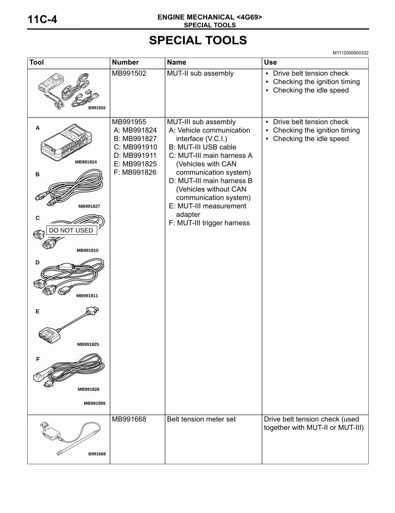
SPECIAL TOOLSM1112000600332
Tool Number Name UseMB991502 MUT-II sub assembly • Drive belt tension check
• Checking the ignition timing• Checking the idle speed
MB991955A: MB991824B: MB991827C: MB991910D: MB991911E: MB991825F: MB991826
MUT-III sub assemblyA: Vehicle communication
interface (V.C.I.)B: MUT-III USB cableC: MUT-III main harness A
(Vehicles with CAN communication system)
D: MUT-III main harness B (Vehicles without CAN communication system)
E: MUT-III measurement adapter
F: MUT-III trigger harness
• Drive belt tension check• Checking the ignition timing• Checking the idle speed
MB991668 Belt tension meter set Drive belt tension check (used together with MUT-II or MUT-III)
B991502
MB991910
MB991826
MB991955
MB991911
MB991824
MB991827
MB991825
A
B
C
D
E
F
DO NOT USED
B991668
SPECIAL TOOLSENGINE MECHANICAL <4G69> 11C-5
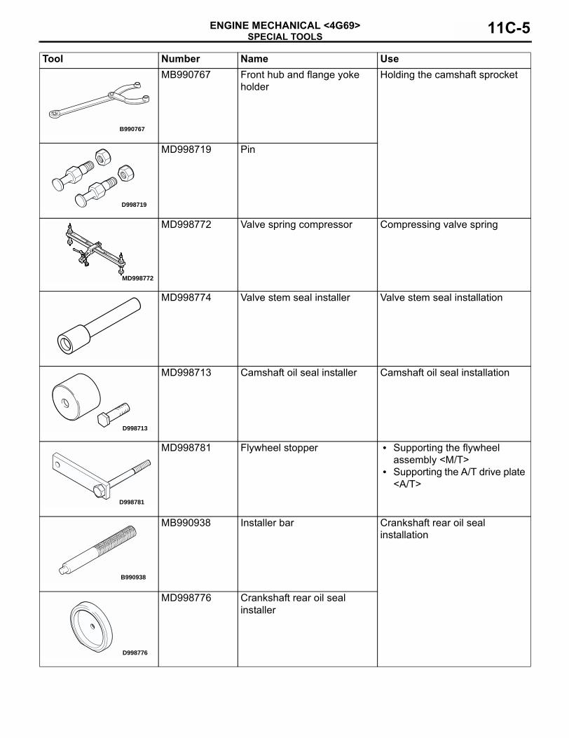
MB990767 Front hub and flange yoke holder
Holding the camshaft sprocket
MD998719 Pin
MD998772 Valve spring compressor Compressing valve spring
MD998774 Valve stem seal installer Valve stem seal installation
MD998713 Camshaft oil seal installer Camshaft oil seal installation
MD998781 Flywheel stopper • Supporting the flywheel assembly <M/T>
• Supporting the A/T drive plate <A/T>
MB990938 Installer bar Crankshaft rear oil seal installation
MD998776 Crankshaft rear oil seal installer
Tool Number Name Use
B990767
D998719
MD998772
D998713
D998781
B990938
D998776
SPECIAL TOOLSENGINE MECHANICAL <4G69>11C-6
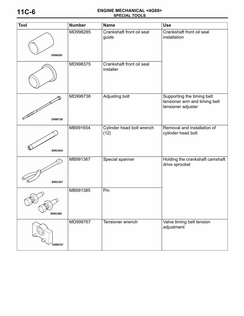
MD998285 Crankshaft front oil seal guide
Crankshaft front oil seal installation
MD998375 Crankshaft front oil seal installer
MD998738 Adjusting bolt Supporting the timing belt tensioner arm and timing belt tensioner adjuster
MB991654 Cylinder head bolt wrench (12)
Removal and installation of cylinder head bolt
MB991367 Special spanner Holding the crankshaft camshaft drive sprocket
MB991385 Pin
MD998767 Tensioner wrench Valve timing belt tension adjustment
Tool Number Name Use
D998285
D998738
B991654
B991367
B991385
D998767
SPECIAL TOOLSENGINE MECHANICAL <4G69> 11C-7
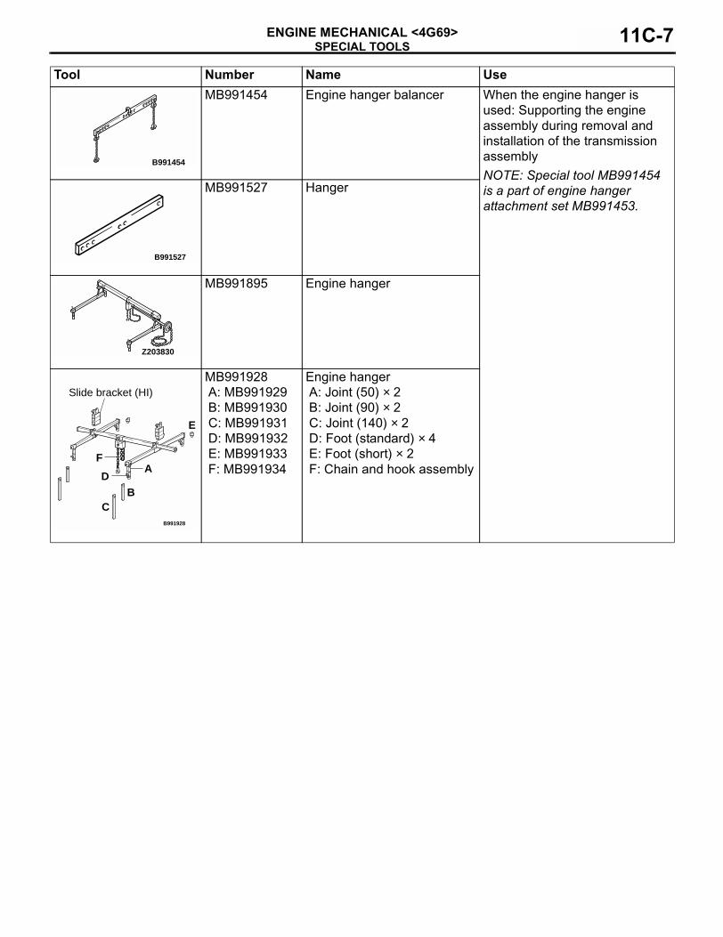
MB991454 Engine hanger balancer When the engine hanger is used: Supporting the engine assembly during removal and installation of the transmission assemblyNOTE: Special tool MB991454 is a part of engine hanger attachment set MB991453.
MB991527 Hanger
MB991895 Engine hanger
MB991928A: MB991929B: MB991930C: MB991931D: MB991932E: MB991933F: MB991934
Engine hangerA: Joint (50) × 2B: Joint (90) × 2C: Joint (140) × 2D: Foot (standard) × 4E: Foot (short) × 2F: Chain and hook assembly
Tool Number Name Use
B991454
B991527
Z203830
B991928
A
BC
D
E
F
Slide bracket (HI)
ON-VEHICLE SERVICEENGINE MECHANICAL <4G69>11C-8
ON-VEHICLE SERVICEDRIVE BELT TENSION CHECK
M1111003100548
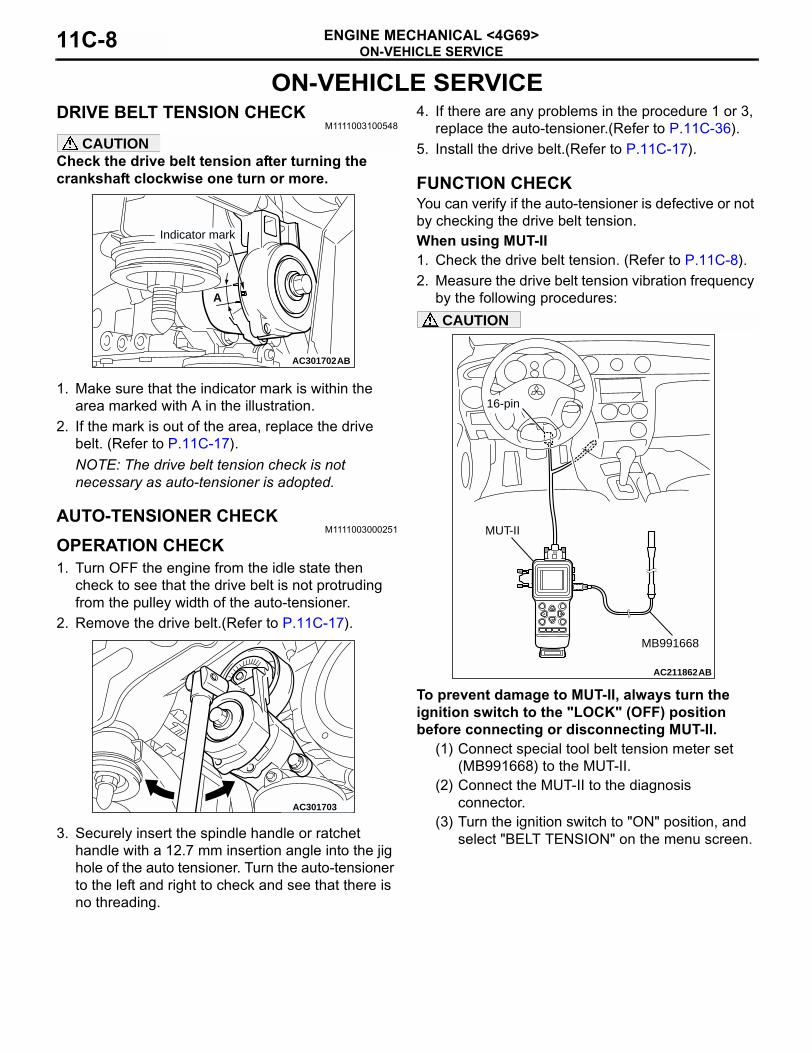
CAUTIONCheck the drive belt tension after turning the crankshaft clockwise one turn or more.
1. Make sure that the indicator mark is within the area marked with A in the illustration.
2. If the mark is out of the area, replace the drive belt. (Refer to P.11C-17).NOTE: The drive belt tension check is not necessary as auto-tensioner is adopted.
AUTO-TENSIONER CHECKM1111003000251
OPERATION CHECK1. Turn OFF the engine from the idle state then
check to see that the drive belt is not protruding from the pulley width of the auto-tensioner.
2. Remove the drive belt.(Refer to P.11C-17).
3. Securely insert the spindle handle or ratchet handle with a 12.7 mm insertion angle into the jig hole of the auto tensioner. Turn the auto-tensioner to the left and right to check and see that there is no threading.
4. If there are any problems in the procedure 1 or 3, replace the auto-tensioner.(Refer to P.11C-36).
5. Install the drive belt.(Refer to P.11C-17).
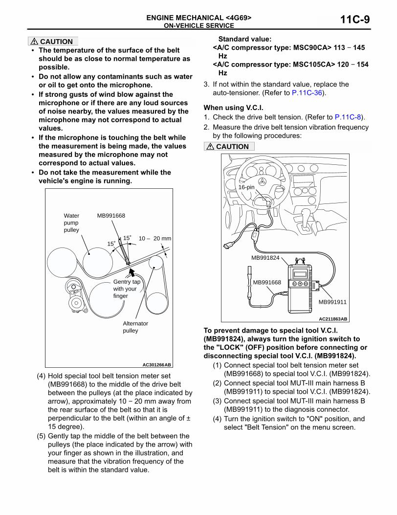
FUNCTION CHECKYou can verify if the auto-tensioner is defective or not by checking the drive belt tension.When using MUT-II1. Check the drive belt tension. (Refer to P.11C-8).2. Measure the drive belt tension vibration frequency
by the following procedures:CAUTION
To prevent damage to MUT-II, always turn the ignition switch to the "LOCK" (OFF) position before connecting or disconnecting MUT-II.
(1) Connect special tool belt tension meter set (MB991668) to the MUT-II.
(2) Connect the MUT-II to the diagnosis connector.
(3) Turn the ignition switch to "ON" position, and select "BELT TENSION" on the menu screen.
AC301702AB
A
Indicator mark
AC301703
AC211862
16-pin
AB
MUT-II
MB991668
ON-VEHICLE SERVICEENGINE MECHANICAL <4G69> 11C-9
CAUTION• The temperature of the surface of the belt
should be as close to normal temperature as possible.
• Do not allow any contaminants such as water or oil to get onto the microphone.
• If strong gusts of wind blow against the microphone or if there are any loud sources of noise nearby, the values measured by the microphone may not correspond to actual values.
• If the microphone is touching the belt while the measurement is being made, the values measured by the microphone may not correspond to actual values.
• Do not take the measurement while the vehicle's engine is running.
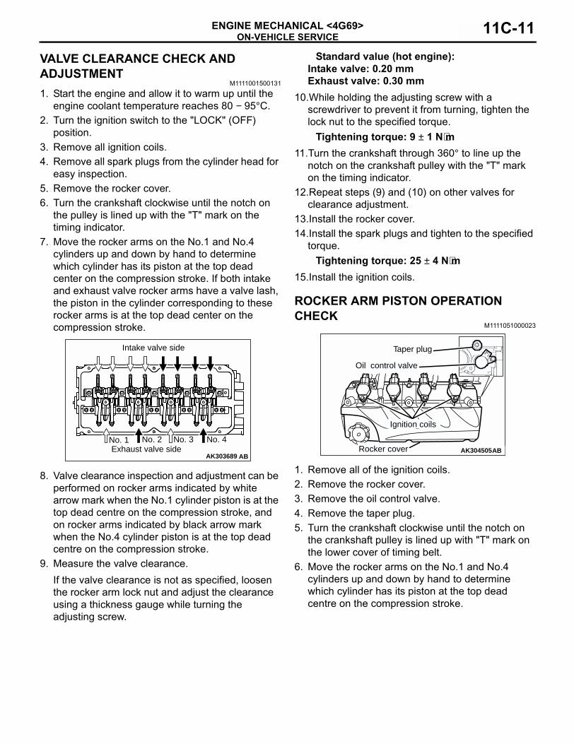
(4) Hold special tool belt tension meter set (MB991668) to the middle of the drive belt between the pulleys (at the place indicated by arrow), approximately 10 − 20 mm away from the rear surface of the belt so that it is perpendicular to the belt (within an angle of ± 15 degree).
(5) Gently tap the middle of the belt between the pulleys (the place indicated by the arrow) with your finger as shown in the illustration, and measure that the vibration frequency of the belt is within the standard value.
Standard value:<A/C compressor type: MSC90CA> 113 − 145
Hz<A/C compressor type: MSC105CA> 120 − 154
Hz3. If not within the standard value, replace the
auto-tensioner. (Refer to P.11C-36).
When using V.C.I.1. Check the drive belt tension. (Refer to P.11C-8).2. Measure the drive belt tension vibration frequency
by the following procedures:CAUTION
To prevent damage to special tool V.C.I. (MB991824), always turn the ignition switch to the "LOCK" (OFF) position before connecting or disconnecting special tool V.C.I. (MB991824).
(1) Connect special tool belt tension meter set (MB991668) to special tool V.C.I. (MB991824).
(2) Connect special tool MUT-III main harness B (MB991911) to special tool V.C.I. (MB991824).
(3) Connect special tool MUT-III main harness B (MB991911) to the diagnosis connector.
(4) Turn the ignition switch to "ON" position, and select "Belt Tension" on the menu screen.
AC301266AB
MB991668
15˚15˚ 10 – 20 mm
Water pumppulley
Alternatorpulley
Gentry tap with your finger
AC211863AB
MB991824
MB991911
16-pin
MB991668

ON-VEHICLE SERVICEENGINE MECHANICAL <4G69>11C-10
CAUTION• The temperature of the surface of the belt
should be as close to normal temperature as possible.
• Do not allow any contaminants such as water or oil to get onto the microphone.
• If strong gusts of wind blow against the microphone or if there are any loud sources of noise nearby, the values measured by the microphone may not correspond to actual values.
• If the microphone is touching the belt while the measurement is being made, the values measured by the microphone may not correspond to actual values.
• Do not take the measurement while the vehicle's engine is running.
(5) Hold special tool belt tension meter set (MB991668) to the middle of the drive belt between the pulleys (at the place indicated by arrow), approximately 10 − 20 mm away from the rear surface of the belt so that it is perpendicular to the belt (within an angle of ± 15 degree).
(6) Gently tap the middle of the belt between the pulleys (the place indicated by the arrow) with your finger as shown in the illustration, and measure that the vibration frequency of the belt is within the standard value.
Standard value:<A/C compressor type: MSC90CA> 113 − 145
Hz<A/C compressor type: MSC105CA> 120 − 154
Hz3. If not within the standard value, replace the
alternator drive belt auto tensioner. (Refer to P.11C-36).
When using a tension gauge1. Check the drive belt tension. (Refer to P.11C-8).
2. Use a belt tension gauge in the middle of the belt between the pulleys (at the place indicated by the arrow) to measure that the belt tension is within the standard value.
Standard value: 340 − 555 N3. If not within the standard value, replace the
auto-tensioner. (Refer to P.11C-36).
AC301266AB
MB991668
15˚15˚ 10 – 20 mm
Water pumppulley
Alternatorpulley
Gentry tap with your finger
AC301267AB
Water pumppulley
Alternatorpulley
Belt tension gauge
ON-VEHICLE SERVICEENGINE MECHANICAL <4G69> 11C-11
VALVE CLEARANCE CHECK AND ADJUSTMENT
M1111001500131
1. Start the engine and allow it to warm up until the engine coolant temperature reaches 80 − 95°C.
2. Turn the ignition switch to the "LOCK" (OFF) position.
3. Remove all ignition coils.4. Remove all spark plugs from the cylinder head for
easy inspection.5. Remove the rocker cover.6. Turn the crankshaft clockwise until the notch on
the pulley is lined up with the "T" mark on the timing indicator.
7. Move the rocker arms on the No.1 and No.4 cylinders up and down by hand to determine which cylinder has its piston at the top dead center on the compression stroke. If both intake and exhaust valve rocker arms have a valve lash, the piston in the cylinder corresponding to these rocker arms is at the top dead center on the compression stroke.
8. Valve clearance inspection and adjustment can be performed on rocker arms indicated by white arrow mark when the No.1 cylinder piston is at the top dead centre on the compression stroke, and on rocker arms indicated by black arrow mark when the No.4 cylinder piston is at the top dead centre on the compression stroke.
9. Measure the valve clearance.If the valve clearance is not as specified, loosen the rocker arm lock nut and adjust the clearance using a thickness gauge while turning the adjusting screw.
Standard value (hot engine):Intake valve: 0.20 mmExhaust valve: 0.30 mm
10.While holding the adjusting screw with a screwdriver to prevent it from turning, tighten the lock nut to the specified torque.
Tightening torque: 9 ± 1 N⋅m11.Turn the crankshaft through 360° to line up the
notch on the crankshaft pulley with the "T" mark on the timing indicator.
12.Repeat steps (9) and (10) on other valves for clearance adjustment.
13.Install the rocker cover.14.Install the spark plugs and tighten to the specified
torque.Tightening torque: 25 ± 4 N⋅m
15.Install the ignition coils.
ROCKER ARM PISTON OPERATION CHECK
M1111051000023
1. Remove all of the ignition coils.2. Remove the rocker cover.3. Remove the oil control valve.4. Remove the taper plug.5. Turn the crankshaft clockwise until the notch on
the crankshaft pulley is lined up with "T" mark on the lower cover of timing belt.
6. Move the rocker arms on the No.1 and No.4 cylinders up and down by hand to determine which cylinder has its piston at the top dead centre on the compression stroke.
AK303689 ABExhaust valve side
No. 1 No. 2 No. 3 No. 4
Intake valve side
AK304505AB
Taper plug
Oil control valve
Ignition coils
Rocker cover
ON-VEHICLE SERVICEENGINE MECHANICAL <4G69>11C-12
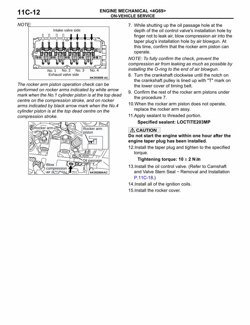
NOTE:
The rocker arm piston operation check can be performed on rocker arms indicated by white arrow mark when the No.1 cylinder piston is at the top dead centre on the compression stroke, and on rocker arms indicated by black arrow mark when the No.4 cylinder piston is at the top dead centre on the compression stroke.
7. While shutting up the oil passage hole at the depth of the oil control valve's installation hole by finger not to leak air, blow compression air into the taper plug's installation hole by air blowgun. At this time, confirm that the rocker arm piston can operate.
NOTE: To fully confirm the check, prevent the compression air from leaking as much as possible by installing the O-ring to the end of air blowgun.8. Turn the crankshaft clockwise until the notch on
the crankshaft pulley is lined up with "T" mark on the lower cover of timing belt.
9. Confirm the rest of the rocker arm pistons under the procedure 7.
10.When the rocker arm piston does not operate, replace the rocker arm assy.
11.Apply sealant to threaded portion.Specified sealant: LOCTITE203MP
CAUTIONDo not start the engine within one hour after the engine taper plug has been installed.12.Install the taper plug and tighten to the specified
torque.Tightening torque: 10 ± 2 N⋅m
13.Install the oil control valve. (Refer to Camshaft and Valve Stem Seal − Removal and Installation P.11C-18.)
14.Install all of the ignition coils.15.Install the rocker cover.
AK303689 ACExhaust valve side
No. 1 No. 2 No. 3 No. 4
Intake valve side
AK302684AC
Rocker armpiston
Blowcompressionair
Oil passage
Rocker arm
ON-VEHICLE SERVICEENGINE MECHANICAL <4G69> 11C-13
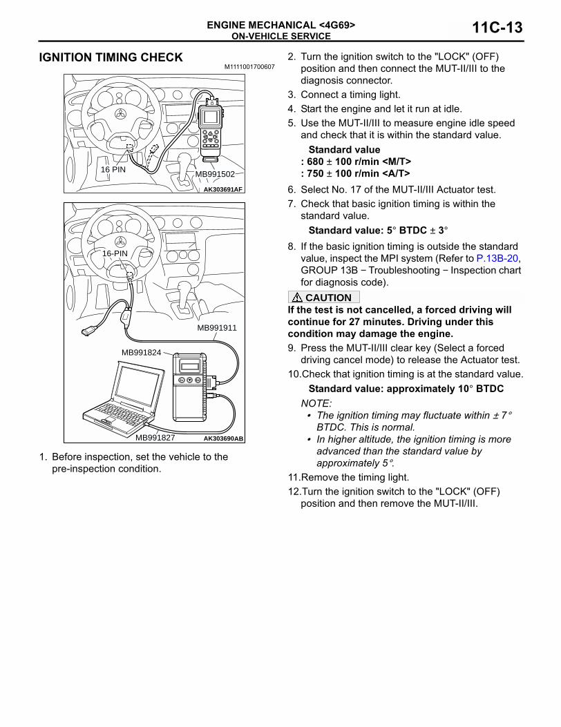
IGNITION TIMING CHECKM1111001700607
1. Before inspection, set the vehicle to the pre-inspection condition.
2. Turn the ignition switch to the "LOCK" (OFF) position and then connect the MUT-II/III to the diagnosis connector.
3. Connect a timing light.4. Start the engine and let it run at idle.5. Use the MUT-II/III to measure engine idle speed
and check that it is within the standard value.Standard value
: 680 ± 100 r/min <M/T>: 750 ± 100 r/min <A/T>
6. Select No. 17 of the MUT-II/III Actuator test.7. Check that basic ignition timing is within the
standard value.Standard value: 5° BTDC ± 3°
8. If the basic ignition timing is outside the standard value, inspect the MPI system (Refer to P.13B-20, GROUP 13B − Troubleshooting − Inspection chart for diagnosis code).CAUTION
If the test is not cancelled, a forced driving will continue for 27 minutes. Driving under this condition may damage the engine.9. Press the MUT-II/III clear key (Select a forced
driving cancel mode) to release the Actuator test.10.Check that ignition timing is at the standard value.
Standard value: approximately 10° BTDCNOTE: .• The ignition timing may fluctuate within ± 7°
BTDC. This is normal.• In higher altitude, the ignition timing is more
advanced than the standard value by approximately 5°.
11.Remove the timing light.12.Turn the ignition switch to the "LOCK" (OFF)
position and then remove the MUT-II/III.
AK303691AF
MB99150216 PIN
AK303690AB
MB991911
16-PIN
MB991827
MB991824
ON-VEHICLE SERVICEENGINE MECHANICAL <4G69>11C-14
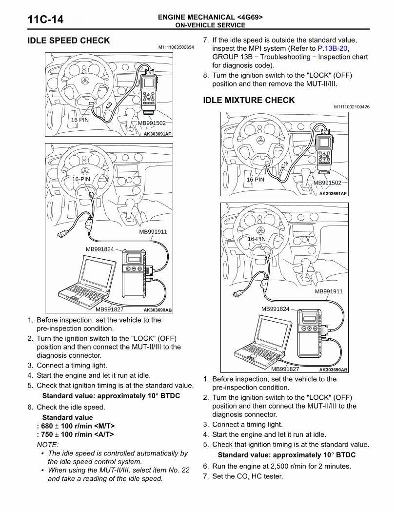
IDLE SPEED CHECK M1111003500654
1. Before inspection, set the vehicle to the pre-inspection condition.
2. Turn the ignition switch to the "LOCK" (OFF) position and then connect the MUT-II/III to the diagnosis connector.
3. Connect a timing light.4. Start the engine and let it run at idle.5. Check that ignition timing is at the standard value.
Standard value: approximately 10° BTDC6. Check the idle speed.
Standard value: 680 ± 100 r/min <M/T>: 750 ± 100 r/min <A/T>NOTE: .• The idle speed is controlled automatically by
the idle speed control system.• When using the MUT-II/III, select item No. 22
and take a reading of the idle speed.
7. If the idle speed is outside the standard value, inspect the MPI system (Refer to P.13B-20, GROUP 13B − Troubleshooting − Inspection chart for diagnosis code).
8. Turn the ignition switch to the "LOCK" (OFF) position and then remove the MUT-II/III.
IDLE MIXTURE CHECKM1111002100426
1. Before inspection, set the vehicle to the pre-inspection condition.
2. Turn the ignition switch to the "LOCK" (OFF) position and then connect the MUT-II/III to the diagnosis connector.
3. Connect a timing light.4. Start the engine and let it run at idle.5. Check that ignition timing is at the standard value.
Standard value: approximately 10° BTDC6. Run the engine at 2,500 r/min for 2 minutes.7. Set the CO, HC tester.
AK303691AF
MB99150216 PIN
AK303690AB
MB991911
16-PIN
MB991827
MB991824
AK303691AF
MB99150216 PIN
AK303690AB
MB991911
16-PIN
MB991827
MB991824
ON-VEHICLE SERVICEENGINE MECHANICAL <4G69> 11C-15
8. Check the CO contents and the HC contents at idle.
Standard valueCO contents: 0.5 % or lessHC contents: 100 ppm or less
9. If there is a deviation from the standard value, check the following items:
• Diagnosis output• Fuel pressure• Injector• Ignition coil, spark plug• EGR control system• Evaporative emission control system• Compression pressure
NOTE: Replace the three way catalyst when the CO and HC contents are not within the standard value, even though the result of the inspection is normal on all items.
10.Turn the ignition switch to the "LOCK" (OFF) position and then remove the MUT-II/III.
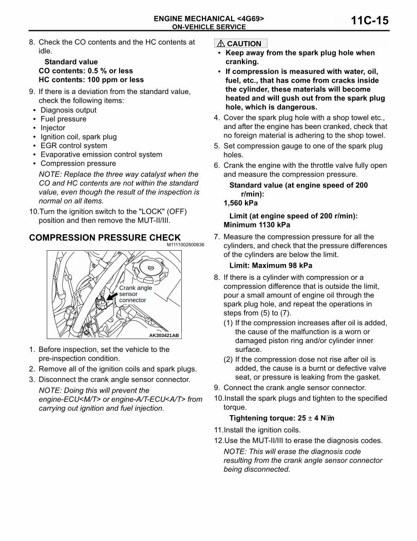
COMPRESSION PRESSURE CHECKM1111002600636
1. Before inspection, set the vehicle to the pre-inspection condition.
2. Remove all of the ignition coils and spark plugs.3. Disconnect the crank angle sensor connector.
NOTE: Doing this will prevent the engine-ECU<M/T> or engine-A/T-ECU<A/T> from carrying out ignition and fuel injection.
CAUTION• Keep away from the spark plug hole when
cranking.• If compression is measured with water, oil,
fuel, etc., that has come from cracks inside the cylinder, these materials will become heated and will gush out from the spark plug hole, which is dangerous.
4. Cover the spark plug hole with a shop towel etc., and after the engine has been cranked, check that no foreign material is adhering to the shop towel.
5. Set compression gauge to one of the spark plug holes.
6. Crank the engine with the throttle valve fully open and measure the compression pressure.
Standard value (at engine speed of 200 r/min):
1,560 kPaLimit (at engine speed of 200 r/min):
Minimum 1130 kPa7. Measure the compression pressure for all the
cylinders, and check that the pressure differences of the cylinders are below the limit.
Limit: Maximum 98 kPa8. If there is a cylinder with compression or a
compression difference that is outside the limit, pour a small amount of engine oil through the spark plug hole, and repeat the operations in steps from (5) to (7).(1) If the compression increases after oil is added,
the cause of the malfunction is a worn or damaged piston ring and/or cylinder inner surface.
(2) If the compression dose not rise after oil is added, the cause is a burnt or defective valve seat, or pressure is leaking from the gasket.
9. Connect the crank angle sensor connector.10.Install the spark plugs and tighten to the specified
torque.Tightening torque: 25 ± 4 N⋅m
11.Install the ignition coils.12.Use the MUT-II/III to erase the diagnosis codes.
NOTE: This will erase the diagnosis code resulting from the crank angle sensor connector being disconnected.
AK303421AB
Crank anglesensorconnector
ON-VEHICLE SERVICEENGINE MECHANICAL <4G69>11C-16
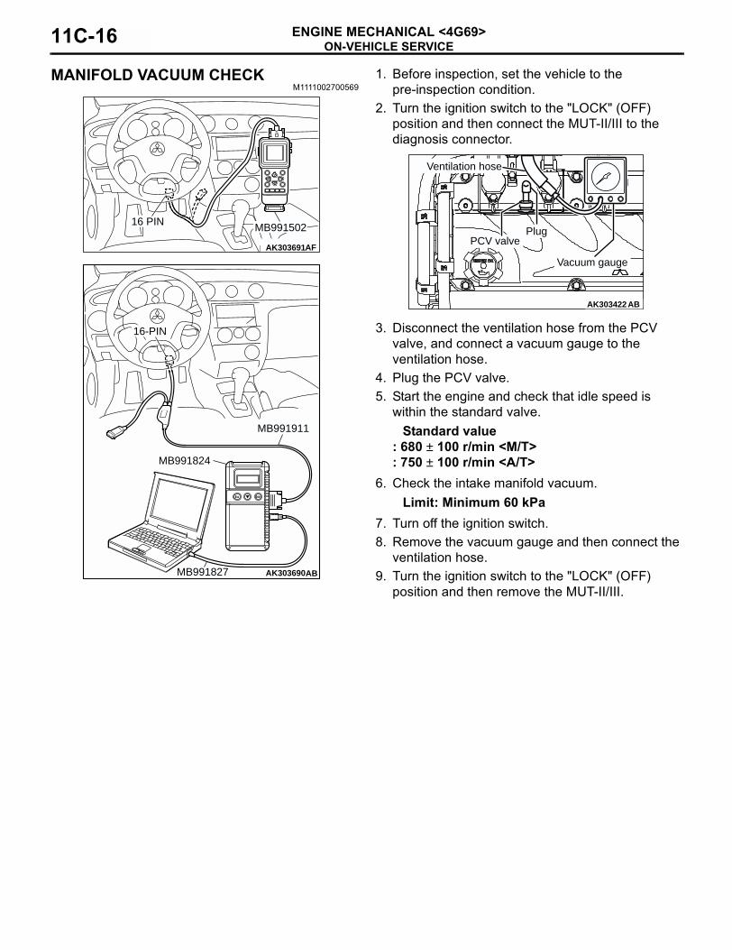
MANIFOLD VACUUM CHECKM1111002700569
1. Before inspection, set the vehicle to the pre-inspection condition.
2. Turn the ignition switch to the "LOCK" (OFF) position and then connect the MUT-II/III to the diagnosis connector.
3. Disconnect the ventilation hose from the PCV valve, and connect a vacuum gauge to the ventilation hose.
4. Plug the PCV valve.5. Start the engine and check that idle speed is
within the standard valve.Standard value
: 680 ± 100 r/min <M/T>: 750 ± 100 r/min <A/T>
6. Check the intake manifold vacuum.Limit: Minimum 60 kPa
7. Turn off the ignition switch.8. Remove the vacuum gauge and then connect the
ventilation hose.9. Turn the ignition switch to the "LOCK" (OFF)
position and then remove the MUT-II/III.
AK303691AF
MB99150216 PIN
AK303690AB
MB991911
16-PIN
MB991827
MB991824
AK303422 AB
Vacuum gauge
PCV valve
Ventilation hose
Plug
CRANKSHAFT PULLEYENGINE MECHANICAL <4G69> 11C-17
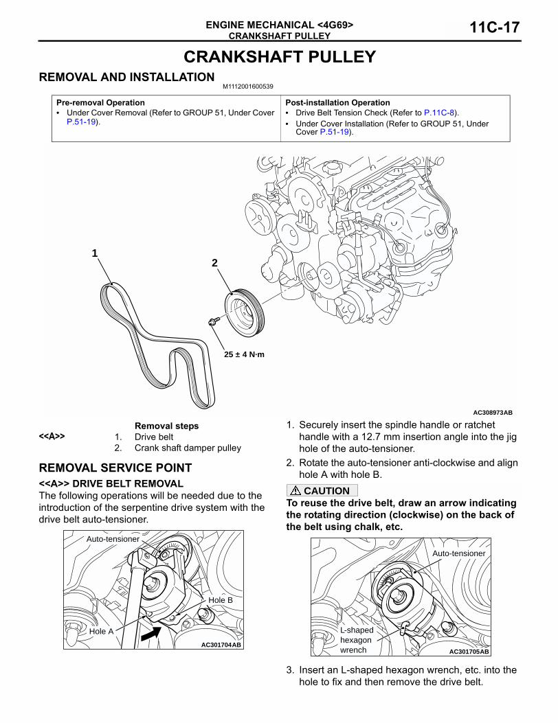
CRANKSHAFT PULLEYREMOVAL AND INSTALLATION
M1112001600539
REMOVAL SERVICE POINT<<A>> DRIVE BELT REMOVALThe following operations will be needed due to the introduction of the serpentine drive system with the drive belt auto-tensioner.
1. Securely insert the spindle handle or ratchet handle with a 12.7 mm insertion angle into the jig hole of the auto-tensioner.
2. Rotate the auto-tensioner anti-clockwise and align hole A with hole B.CAUTION
To reuse the drive belt, draw an arrow indicating the rotating direction (clockwise) on the back of the belt using chalk, etc.
3. Insert an L-shaped hexagon wrench, etc. into the hole to fix and then remove the drive belt.
Pre-removal Operation• Under Cover Removal (Refer to GROUP 51, Under Cover
P.51-19).
Post-installation Operation• Drive Belt Tension Check (Refer to P.11C-8).• Under Cover Installation (Refer to GROUP 51, Under
Cover P.51-19).
AC308973AB
25 ± 4 N·m
12
Removal steps<<A>> 1. Drive belt
2. Crank shaft damper pulley
AC301703
AC301704AB
Hole A
Auto-tensioner
Hole B
AC301705AB
L-shapedhexagonwrench
Auto-tensioner

CAMSHAFT AND VALVE STEM SEALENGINE MECHANICAL <4G69>11C-18
CAMSHAFT AND VALVE STEM SEALREMOVAL AND INSTALLATION
M1112006600330
CAUTION* Remove and assemble the marked parts in each cylinder unit.
Pre-removal Operation• Air Cleaner Removal (Refer to GROUP 15, Air Cleaner
P.15-4).• Ignition Coils Removal (Refer to GROUP 16, Ignition
System − Ignition Coil P.16-41).• Timing Belt Upper Cover Removal (Refer to P.11C-36).
Post-installation Operation• Timing Belt Upper Cover Installation (Refer to P.11C-36).• Ignition Coils Installation (Refer to GROUP 16, Ignition
System − Ignition Coil P.16-41).• Air Cleaner Installation (Refer to GROUP 15, Air Cleaner
P.15-4).• Drive Belt Tension Check (Refer to P.11C-8).• Valve Clearance Check and Adjustment (Refer to
P.11C-11).
AC308974
1
10
9
8
7
5
4
3
2
N
AB
N
11 ± 1 N·m
3.5 ± 0.5 N·m
24 ± 3 N·m
44 ± 5 N·m
9.0 ± 2.0 N·m
(Engine oil)N6
Camshaft removal steps1. Rocker cover PCV hose connection2. Rocker cover breather hose
connection3. Control wiring harness connection4. Engine hanger
>>J<< 5. Oil control valve>>J<< 6. O-ring
7. Rocker cover assembly8. Rocker cover gasket9. Spark plug guide oil seals10. Accumulator assembly• Valve timing belt (Refer to
P.11C-36).
Camshaft removal steps
CAMSHAFT AND VALVE STEM SEALENGINE MECHANICAL <4G69> 11C-19
AC308975AB
17
16
15
13
12
11
28*
27*
26*25*24*
2221
20
18
19
N
28*
25*24*
14 ± 1 N·m
22 ± 4 N·m
13 ± 1 N·m
31 ± 3 N·m
47 ± 7 N·m
25 ± 4 N·m
89 ± 9 N·mN
N
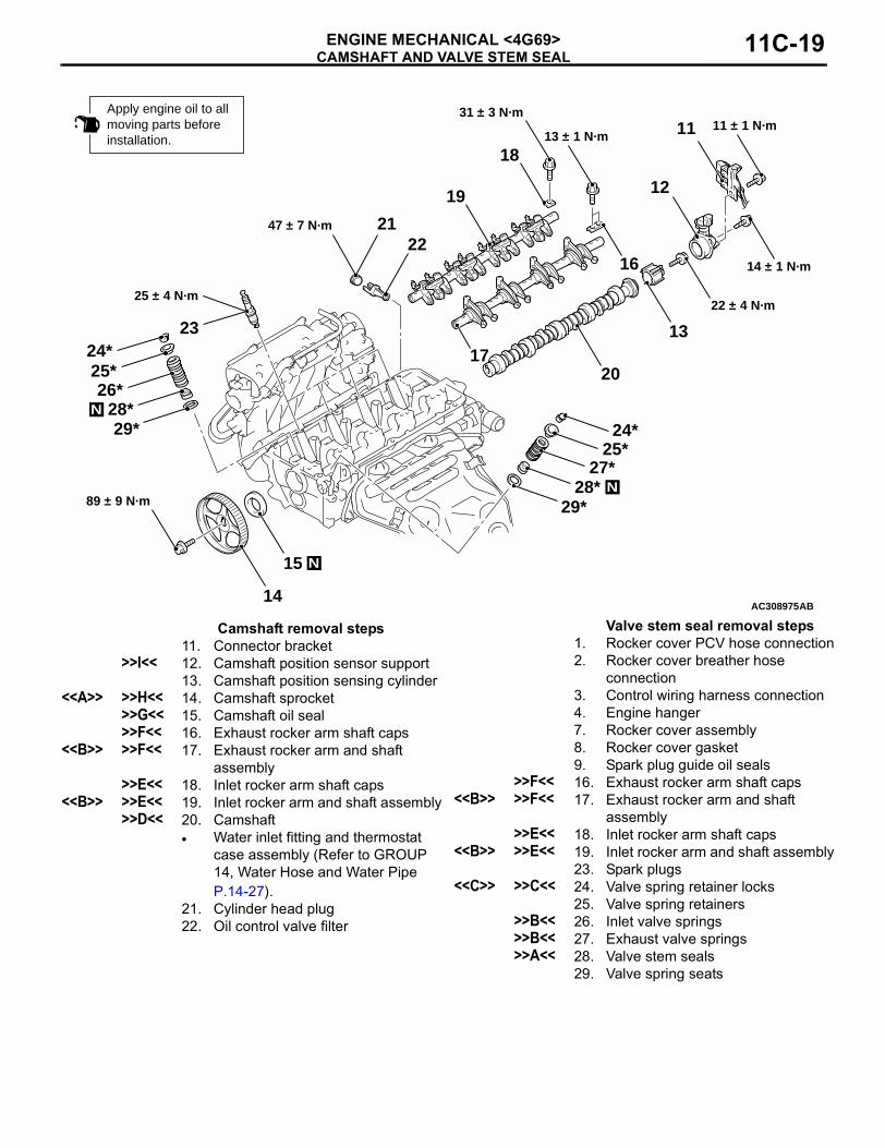
Apply engine oil to all moving parts beforeinstallation.
14
23
29*
29*
11 ± 1 N·m
Camshaft removal steps11. Connector bracket
>>I<< 12. Camshaft position sensor support13. Camshaft position sensing cylinder
<<A>> >>H<< 14. Camshaft sprocket>>G<< 15. Camshaft oil seal>>F<< 16. Exhaust rocker arm shaft caps
<<B>> >>F<< 17. Exhaust rocker arm and shaft assembly
>>E<< 18. Inlet rocker arm shaft caps<<B>> >>E<< 19. Inlet rocker arm and shaft assembly
>>D<< 20. Camshaft• Water inlet fitting and thermostat
case assembly (Refer to GROUP 14, Water Hose and Water Pipe P.14-27).
21. Cylinder head plug22. Oil control valve filter
Valve stem seal removal steps1. Rocker cover PCV hose connection2. Rocker cover breather hose
connection3. Control wiring harness connection4. Engine hanger7. Rocker cover assembly8. Rocker cover gasket9. Spark plug guide oil seals
>>F<< 16. Exhaust rocker arm shaft caps<<B>> >>F<< 17. Exhaust rocker arm and shaft
assembly>>E<< 18. Inlet rocker arm shaft caps
<<B>> >>E<< 19. Inlet rocker arm and shaft assembly23. Spark plugs
<<C>> >>C<< 24. Valve spring retainer locks25. Valve spring retainers
>>B<< 26. Inlet valve springs>>B<< 27. Exhaust valve springs>>A<< 28. Valve stem seals
29. Valve spring seats
CAMSHAFT AND VALVE STEM SEALENGINE MECHANICAL <4G69>11C-20
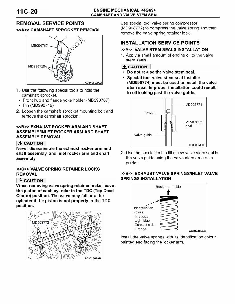
REMOVAL SERVICE POINTS<<A>> CAMSHAFT SPROCKET REMOVAL
1. Use the following special tools to hold the camshaft sprocket.
• Front hub and flange yoke holder (MB990767)• Pin (MD998719)
2. Loosen the camshaft sprocket mounting bolt and remove the camshaft sprocket.
<<B>> EXHAUST ROCKER ARM AND SHAFT ASSEMBLY/INLET ROCKER ARM AND SHAFT ASSEMBLY REMOVAL
CAUTIONNever disassemble the exhaust rocker arm and shaft assembly, and inlet rocker arm and shaft assembly.
<<C>> VALVE SPRING RETAINER LOCKS REMOVAL
CAUTIONWhen removing valve spring retainer locks, leave the piston of each cylinder in the TDC (Top Dead Centre) position. The valve may fall into the cylinder if the piston is not properly in the TDC position.
Use special tool valve spring compressor (MD998772) to compress the valve spring and then remove the valve spring retainer lock.
INSTALLATION SERVICE POINTS>>A<< VALVE STEM SEALS INSTALLATION1. Apply a small amount of engine oil to the valve
stem seals.CAUTION
• Do not re-use the valve stem seal.• Special tool valve stem seal installer
(MD998774) must be used to install the valve stem seal. Improper installation could result in oil leaking past the valve guide.
2. Use the special tool to fill a new valve stem seal in the valve guide using the valve stem area as a guide.
>>B<< EXHAUST VALVE SPRINGS/INLET VALVE SPRINGS INSTALLATION
Install the valve springs with its identification colour painted end facing the locker arm.
AC102532AB
MB990767
MD998719
AC301867AB
MD998772
AC308654AB
MD998774
Valve
Valve guide
Valve stem seal
AC107415AC
Rocker arm side
Identificationcolour Inlet side: Light blue Exhaust side: Orange
CAMSHAFT AND VALVE STEM SEALENGINE MECHANICAL <4G69> 11C-21
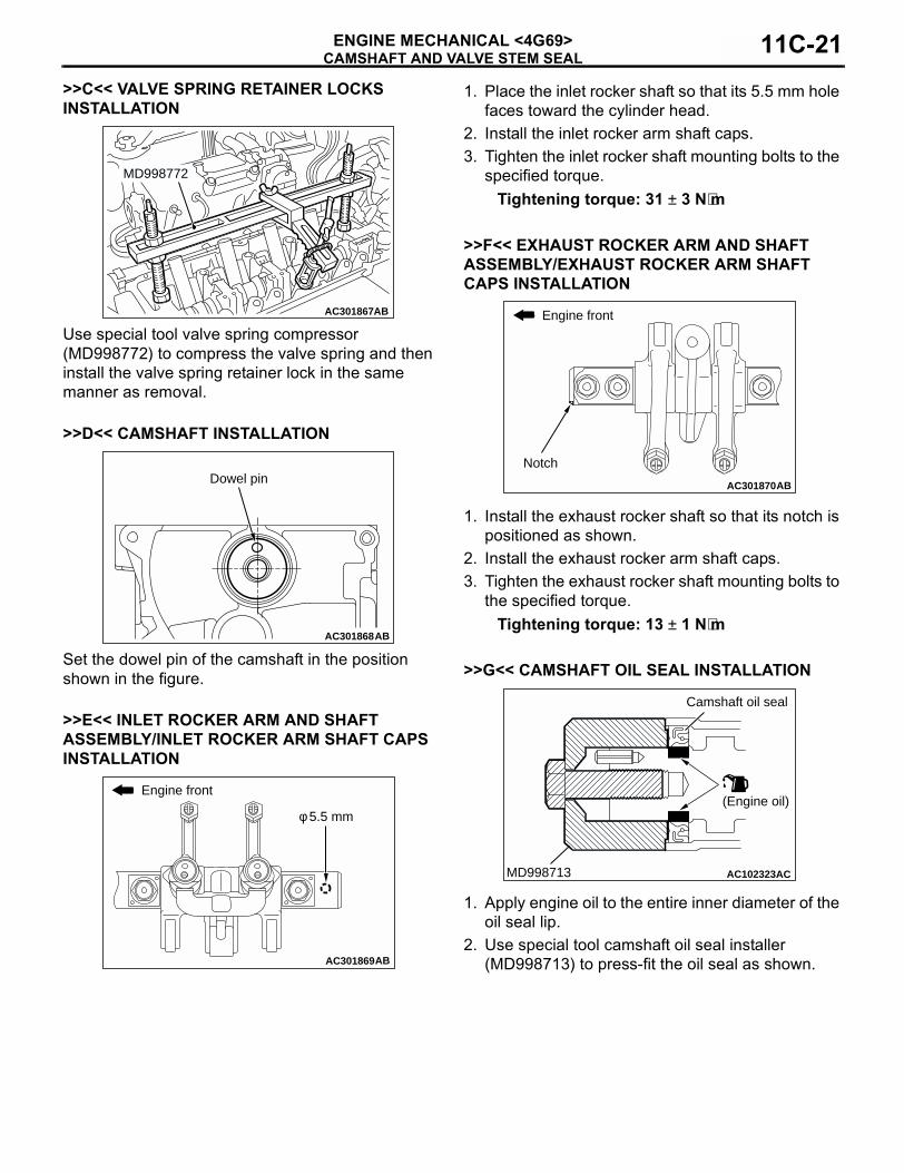
>>C<< VALVE SPRING RETAINER LOCKS INSTALLATION
Use special tool valve spring compressor (MD998772) to compress the valve spring and then install the valve spring retainer lock in the same manner as removal.
>>D<< CAMSHAFT INSTALLATION
Set the dowel pin of the camshaft in the position shown in the figure.
>>E<< INLET ROCKER ARM AND SHAFT ASSEMBLY/INLET ROCKER ARM SHAFT CAPS INSTALLATION
1. Place the inlet rocker shaft so that its 5.5 mm hole faces toward the cylinder head.
2. Install the inlet rocker arm shaft caps.3. Tighten the inlet rocker shaft mounting bolts to the
specified torque.Tightening torque: 31 ± 3 N⋅m
>>F<< EXHAUST ROCKER ARM AND SHAFT ASSEMBLY/EXHAUST ROCKER ARM SHAFT CAPS INSTALLATION
1. Install the exhaust rocker shaft so that its notch is positioned as shown.
2. Install the exhaust rocker arm shaft caps.3. Tighten the exhaust rocker shaft mounting bolts to
the specified torque.Tightening torque: 13 ± 1 N⋅m
>>G<< CAMSHAFT OIL SEAL INSTALLATION
1. Apply engine oil to the entire inner diameter of the oil seal lip.
2. Use special tool camshaft oil seal installer (MD998713) to press-fit the oil seal as shown.
AC301867AB
MD998772
AC301868AB
Dowel pin
AC301869AB
φ 5.5 mm
Engine front
AC301870AB
Engine front
Notch
AC102323ACMD998713
Camshaft oil seal
(Engine oil)
CAMSHAFT AND VALVE STEM SEALENGINE MECHANICAL <4G69>11C-22
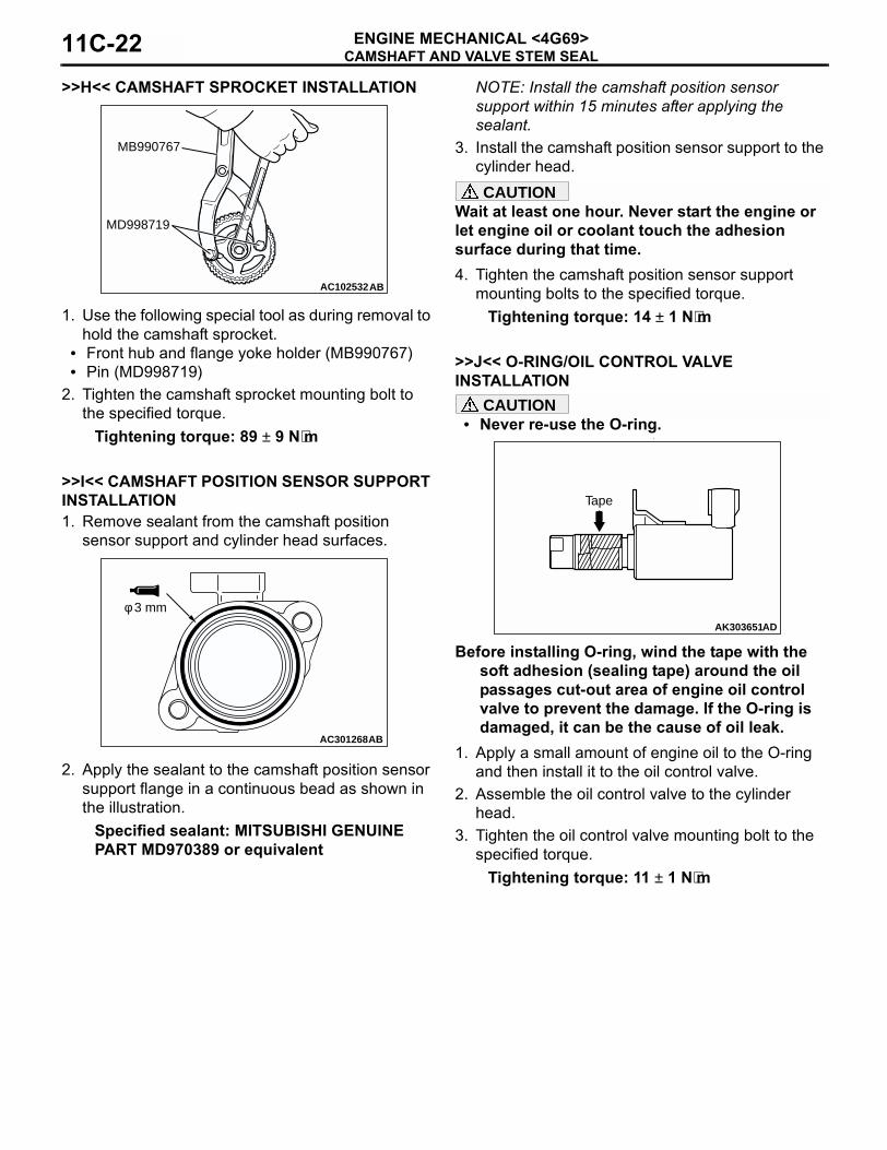
>>H<< CAMSHAFT SPROCKET INSTALLATION
1. Use the following special tool as during removal to hold the camshaft sprocket.
• Front hub and flange yoke holder (MB990767)• Pin (MD998719)
2. Tighten the camshaft sprocket mounting bolt to the specified torque.
Tightening torque: 89 ± 9 N⋅m
>>I<< CAMSHAFT POSITION SENSOR SUPPORT INSTALLATION1. Remove sealant from the camshaft position
sensor support and cylinder head surfaces.
2. Apply the sealant to the camshaft position sensor support flange in a continuous bead as shown in the illustration.
Specified sealant: MITSUBISHI GENUINE PART MD970389 or equivalent
NOTE: Install the camshaft position sensor support within 15 minutes after applying the sealant.
3. Install the camshaft position sensor support to the cylinder head.CAUTION
Wait at least one hour. Never start the engine or let engine oil or coolant touch the adhesion surface during that time.4. Tighten the camshaft position sensor support
mounting bolts to the specified torque.Tightening torque: 14 ± 1 N⋅m
>>J<< O-RING/OIL CONTROL VALVE INSTALLATION
CAUTION• Never re-use the O-ring.
•
Before installing O-ring, wind the tape with the soft adhesion (sealing tape) around the oil passages cut-out area of engine oil control valve to prevent the damage. If the O-ring is damaged, it can be the cause of oil leak.
1. Apply a small amount of engine oil to the O-ring and then install it to the oil control valve.
2. Assemble the oil control valve to the cylinder head.
3. Tighten the oil control valve mounting bolt to the specified torque.
Tightening torque: 11 ± 1 N⋅m
AC102532AB
MB990767
MD998719
AC301268AB
φ 3 mmAK303651AD
Tape
OIL PANENGINE MECHANICAL <4G69> 11C-23
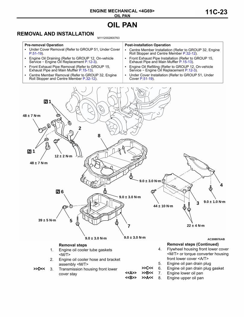
OIL PANREMOVAL AND INSTALLATION
M1112002800763
Pre-removal Operation• Under Cover Removal (Refer to GROUP 51, Under Cover
P.51-19).• Engine Oil Draining (Refer to GROUP 12, On-vehicle
Service − Engine Oil Replacement P.12-3).• Front Exhaust Pipe Removal (Refer to GROUP 15,
Exhaust Pipe and Main Muffler P.15-13).• Centre Member Removal (Refer to GROUP 32, Engine
Roll Stopper and Centre Member P.32-12).
Post-installation Operation• Centre Member Installation (Refer to GROUP 32, Engine
Roll Stopper and Centre Member P.32-12).• Front Exhaust Pipe Installation (Refer to GROUP 15,
Exhaust Pipe and Main Muffler P.15-13).• Engine Oil Refilling (Refer to GROUP 12, On-vehicle
Service − Engine Oil Replacement P.12-3).• Under Cover Installation (Refer to GROUP 51, Under
Cover P.51-19).
AC308976
N
5
6
8
7
3
4
AB9.0 ± 3.0 N·m
9.0 ± 1.0 N·m44 ± 10 N·m
22 ± 4 N·m
9.0 ± 3.0 N·m
9.0 ± 3.0 N·m
9.0 ± 3.0 N·m
39 ± 5 N·m
2
1
1N
N
48 ± 7 N·m
48 ± 7 N·m
12 ± 2 N·m
Removal steps1. Engine oil cooler tube gaskets
<M/T>2. Engine oil cooler hose and bracket
assembly <M/T>>>D<< 3. Transmission housing front lower
cover stay
4. Flywheel housing front lower cover <M/T> or torque converter housing front lower cover <A/T>
5. Engine oil pan drain plug>>C<< 6. Engine oil pan drain plug gasket
<<A>> >>B<< 7. Engine lower oil pan<<B>> >>A<< 8. Engine upper oil pan
Removal steps (Continued)
OIL PANENGINE MECHANICAL <4G69>11C-24
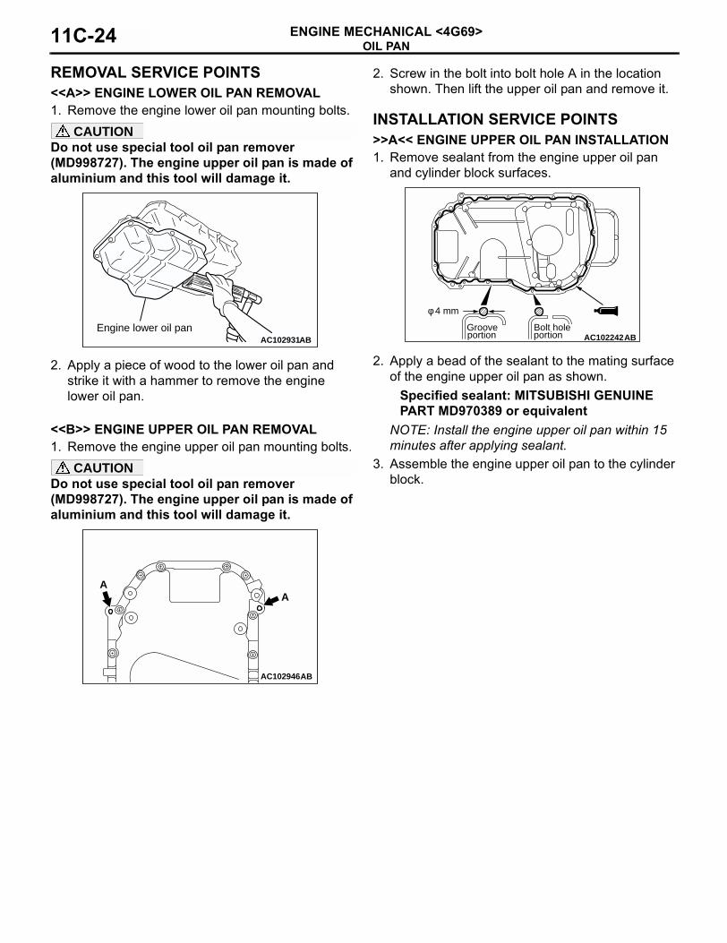
REMOVAL SERVICE POINTS<<A>> ENGINE LOWER OIL PAN REMOVAL1. Remove the engine lower oil pan mounting bolts.
CAUTIONDo not use special tool oil pan remover (MD998727). The engine upper oil pan is made of aluminium and this tool will damage it.
2. Apply a piece of wood to the lower oil pan and strike it with a hammer to remove the engine lower oil pan.
<<B>> ENGINE UPPER OIL PAN REMOVAL1. Remove the engine upper oil pan mounting bolts.
CAUTIONDo not use special tool oil pan remover (MD998727). The engine upper oil pan is made of aluminium and this tool will damage it.
2. Screw in the bolt into bolt hole A in the location shown. Then lift the upper oil pan and remove it.
INSTALLATION SERVICE POINTS>>A<< ENGINE UPPER OIL PAN INSTALLATION1. Remove sealant from the engine upper oil pan
and cylinder block surfaces.
2. Apply a bead of the sealant to the mating surface of the engine upper oil pan as shown.
Specified sealant: MITSUBISHI GENUINE PART MD970389 or equivalent
NOTE: Install the engine upper oil pan within 15 minutes after applying sealant.
3. Assemble the engine upper oil pan to the cylinder block.
AC102931ABEngine lower oil pan
AC102946AB
AA
AC102242ABGroove
φ 4 mm
portionBolt holeportion
OIL PANENGINE MECHANICAL <4G69> 11C-25
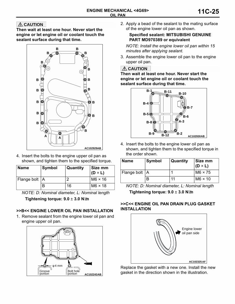
CAUTIONThen wait at least one hour. Never start the engine or let engine oil or coolant touch the sealant surface during that time.
4. Insert the bolts to the engine upper oil pan as shown, and tighten them to the specified torque.
NOTE: D: Nominal diameter, L: Nominal lengthTightening torque: 9.0 ± 3.0 N⋅m
>>B<< ENGINE LOWER OIL PAN INSTALLATION1. Remove sealant from the engine lower oil pan and
engine upper oil pan.
2. Apply a bead of the sealant to the mating surface of the engine lower oil pan as shown.
Specified sealant: MITSUBISHI GENUINE PART MD970389 or equivalent
NOTE: Install the engine lower oil pan within 15 minutes after applying sealant.
3. Assemble the engine lower oil pan to the engine upper oil pan.CAUTION
Then wait at least one hour. Never start the engine or let engine oil or coolant touch the sealant surface during that time.
4. Insert the bolts to the engine lower oil pan as shown, and tighten them to the specified torque in the order shown.
NOTE: D: Nominal diameter, L: Nominal lengthTightening torque: 9.0 ± 3.0 N⋅m
>>C<< ENGINE OIL PAN DRAIN PLUG GASKET INSTALLATION
Replace the gasket with a new one. Install the new gasket in the direction shown in the illustration.
Name Symbol Quantity Size mm (D × L)
Flange bolt A 2 M6 × 16B 16 M6 × 18
AC102929AB
B
B
B
B
B
B
BBB
B
B
B
B
B
B
B
AA
AC102243ABGroove
φ 4 mm
portionBolt holeportion
Name Symbol Quantity Size mm (D × L)
Flange bolt A 1 M6 × 75B 11 M6 × 10
AC102930AB
A-3B-6
B-7
B-10B-11B-1
B-4
B-5
B-12 B-2
B-8
B-9
AC102325AF
Engine lower oil pan side
CRANKSHAFT OIL SEALENGINE MECHANICAL <4G69>11C-26
>>D<< TRANSMISSION HOUSING FRONT LOWER COVER STAY INSTALLATIONInstall the transmission housing front lower cover stay in the following order.1. Tighten the engine side four mounting bolts to the
specified torque.Tightening torque: 22 ± 4 N⋅m
2. Tighten the transmission side two mounting bolts to the specified torque.
Tightening torque: 44 ± 10 N⋅m
INSPECTIONM1112002900254
• Check the oil pan for cracks.• Check the oil pan sealant-coated surface for
damage and deformation.
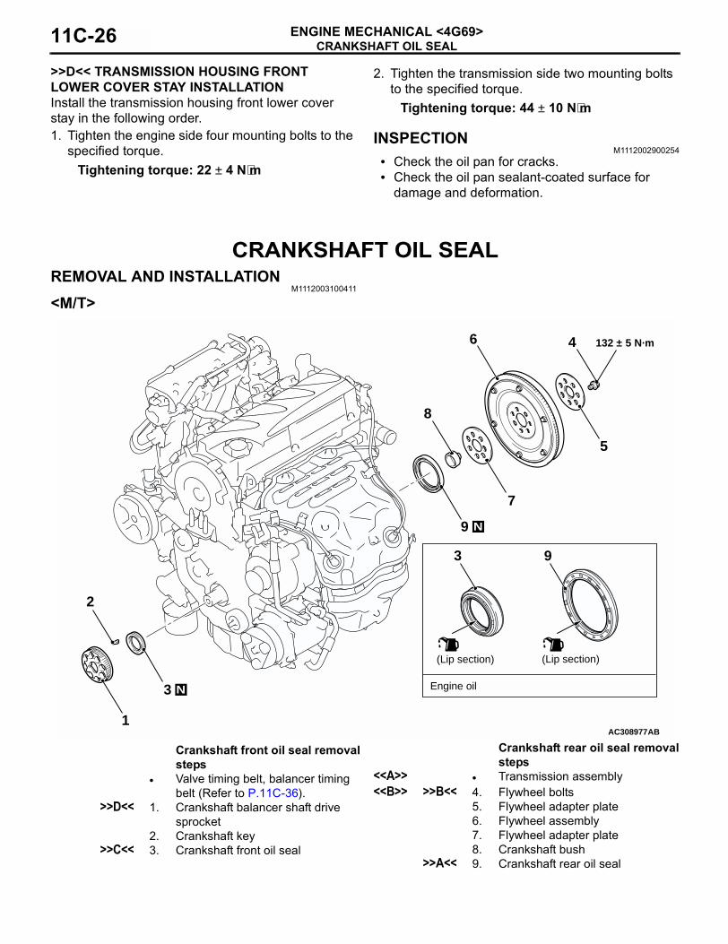
CRANKSHAFT OIL SEALREMOVAL AND INSTALLATION
M1112003100411
<M/T>
AC3089771
2
3 N
9
8
7
6 4
N
132 ± 5 N·m
(Lip section)
Engine oil
AB
(Lip section)
3 9
5
Crankshaft front oil seal removal steps
• Valve timing belt, balancer timing belt (Refer to P.11C-36).
>>D<< 1. Crankshaft balancer shaft drive sprocket
2. Crankshaft key>>C<< 3. Crankshaft front oil seal
Crankshaft rear oil seal removal steps
<<A>> • Transmission assembly<<B>> >>B<< 4. Flywheel bolts
5. Flywheel adapter plate6. Flywheel assembly7. Flywheel adapter plate8. Crankshaft bush
>>A<< 9. Crankshaft rear oil seal
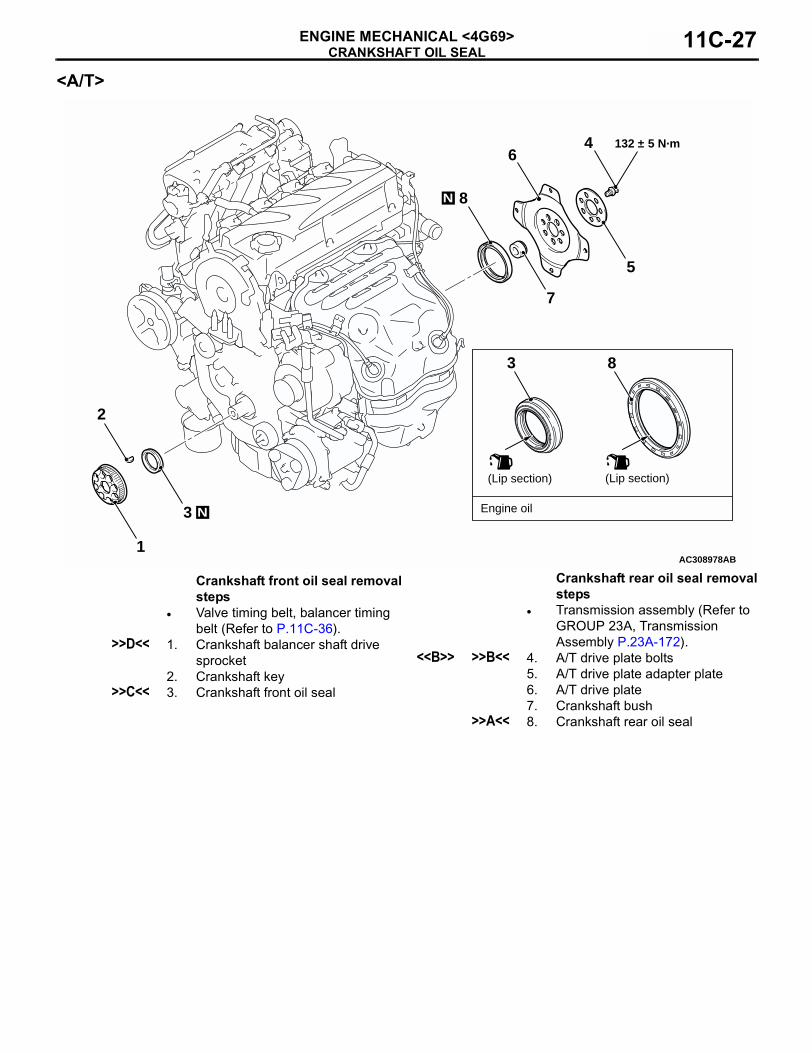
CRANKSHAFT OIL SEALENGINE MECHANICAL <4G69> 11C-27
<A/T>
AC3089781
2
3 N
8
7
64
N
132 ± 5 N·m
(Lip section)
Engine oil
AB
(Lip section)
3 8
5
Crankshaft front oil seal removal steps
• Valve timing belt, balancer timing belt (Refer to P.11C-36).
>>D<< 1. Crankshaft balancer shaft drive sprocket
2. Crankshaft key>>C<< 3. Crankshaft front oil seal
Crankshaft rear oil seal removal steps
• Transmission assembly (Refer to GROUP 23A, Transmission Assembly P.23A-172).
<<B>> >>B<< 4. A/T drive plate bolts5. A/T drive plate adapter plate6. A/T drive plate 7. Crankshaft bush
>>A<< 8. Crankshaft rear oil seal
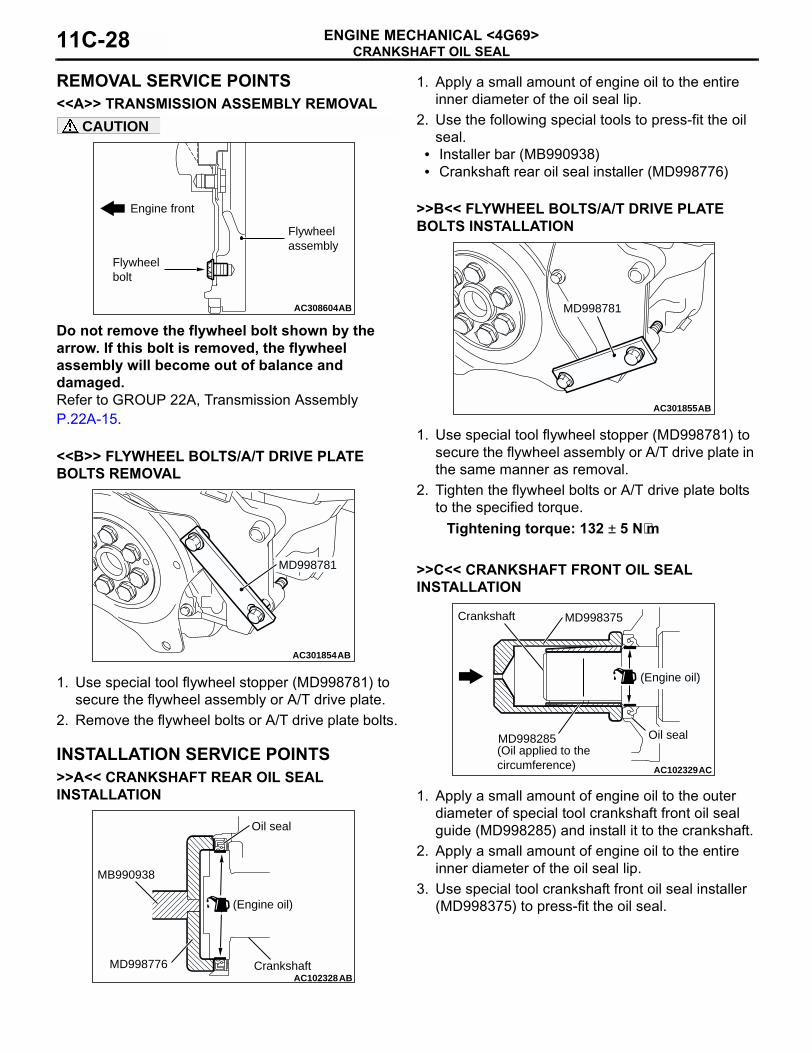
CRANKSHAFT OIL SEALENGINE MECHANICAL <4G69>11C-28
REMOVAL SERVICE POINTS<<A>> TRANSMISSION ASSEMBLY REMOVAL
CAUTION
Do not remove the flywheel bolt shown by the arrow. If this bolt is removed, the flywheel assembly will become out of balance and damaged.Refer to GROUP 22A, Transmission Assembly P.22A-15.
<<B>> FLYWHEEL BOLTS/A/T DRIVE PLATE BOLTS REMOVAL
1. Use special tool flywheel stopper (MD998781) to secure the flywheel assembly or A/T drive plate.
2. Remove the flywheel bolts or A/T drive plate bolts.
INSTALLATION SERVICE POINTS>>A<< CRANKSHAFT REAR OIL SEAL INSTALLATION
1. Apply a small amount of engine oil to the entire inner diameter of the oil seal lip.
2. Use the following special tools to press-fit the oil seal.
• Installer bar (MB990938)• Crankshaft rear oil seal installer (MD998776)
>>B<< FLYWHEEL BOLTS/A/T DRIVE PLATE BOLTS INSTALLATION
1. Use special tool flywheel stopper (MD998781) to secure the flywheel assembly or A/T drive plate in the same manner as removal.
2. Tighten the flywheel bolts or A/T drive plate bolts to the specified torque.
Tightening torque: 132 ± 5 N⋅m
>>C<< CRANKSHAFT FRONT OIL SEAL INSTALLATION
1. Apply a small amount of engine oil to the outer diameter of special tool crankshaft front oil seal guide (MD998285) and install it to the crankshaft.
2. Apply a small amount of engine oil to the entire inner diameter of the oil seal lip.
3. Use special tool crankshaft front oil seal installer (MD998375) to press-fit the oil seal.
AC300897
AC308604
Flywheel bolt
Engine front
AB
Flywheel assembly
AC301854AB
MD998781
AC102328AB
Oil seal
MB990938
MD998776 Crankshaft
(Engine oil)
AC301855AB
MD998781
AC102329AC
MD998285
(Engine oil)
(Oil applied to thecircumference)
Oil seal
Crankshaft MD998375
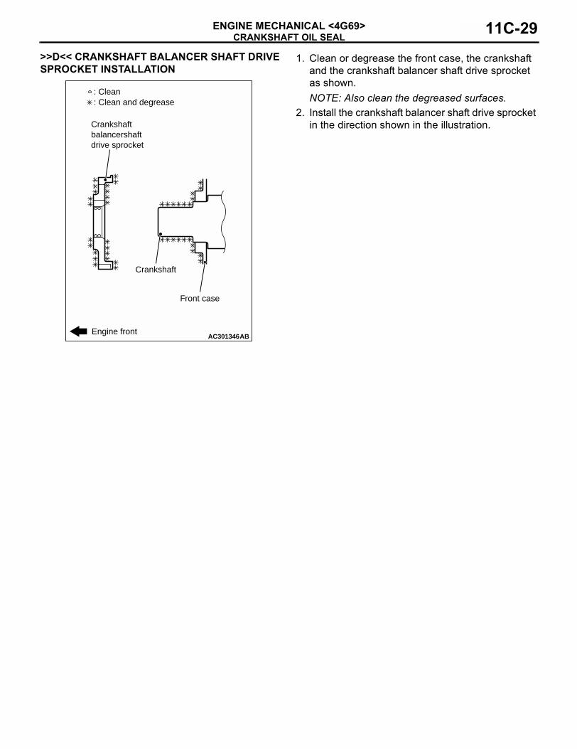
CRANKSHAFT OIL SEALENGINE MECHANICAL <4G69> 11C-29
>>D<< CRANKSHAFT BALANCER SHAFT DRIVE SPROCKET INSTALLATION
1. Clean or degrease the front case, the crankshaft and the crankshaft balancer shaft drive sprocket as shown.NOTE: Also clean the degreased surfaces.
2. Install the crankshaft balancer shaft drive sprocket in the direction shown in the illustration.
AC301346AB
: Clean: Clean and degrease
Crankshaftbalancershaftdrive sprocket
Engine front
Front case
Crankshaft
CYLINDER HEAD GASKETENGINE MECHANICAL <4G69>11C-30
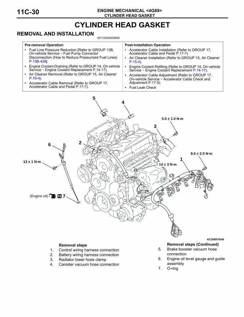
CYLINDER HEAD GASKETREMOVAL AND INSTALLATION
M1112004000848
Pre-removal Operation• Fuel Line Pressure Reduction [Refer to GROUP 13B,
On-vehicle Service − Fuel Pump Connector Disconnection (How to Reduce Pressurized Fuel Lines) P.13B-428].
• Engine Coolant Draining (Refer to GROUP 14, On-vehicle Service − Engine Coolant Replacement P.14-17).
• Air Cleaner Removal (Refer to GROUP 15, Air Cleaner P.15-4).
• Accelerator Cable Removal (Refer to GROUP 17, Accelerator Cable and Pedal P.17-7).
Post-installation Operation• Accelerator Cable Installation (Refer to GROUP 17,
Accelerator Cable and Pedal P.17-7).• Air Cleaner Installation (Refer to GROUP 15, Air Cleaner
P.15-4).• Engine Coolant Refilling (Refer to GROUP 14, On-vehicle
Service − Engine Coolant Replacement P.14-17).• Accelerator Cable Adjustment (Refer to GROUP 17,
On-vehicle Service − Accelerator Cable Check and Adjustment P.17-5).
• Fuel Leak Check
AC308979
N(Engine oil)
13 ± 1 N·m14 ± 3 N·m
9.0 ± 2.0 N·m
5.0 ± 1.0 N·m
1
6
54
3
2
AB
7
Removal steps1. Control wiring harness connection 2. Battery wiring harness connection 3. Radiator lower hose clamp4. Canister vacuum hose connection
5. Brake booster vacuum hose connection
6. Engine oil level gauge and guide assembly
7. O-ring
Removal steps (Continued)
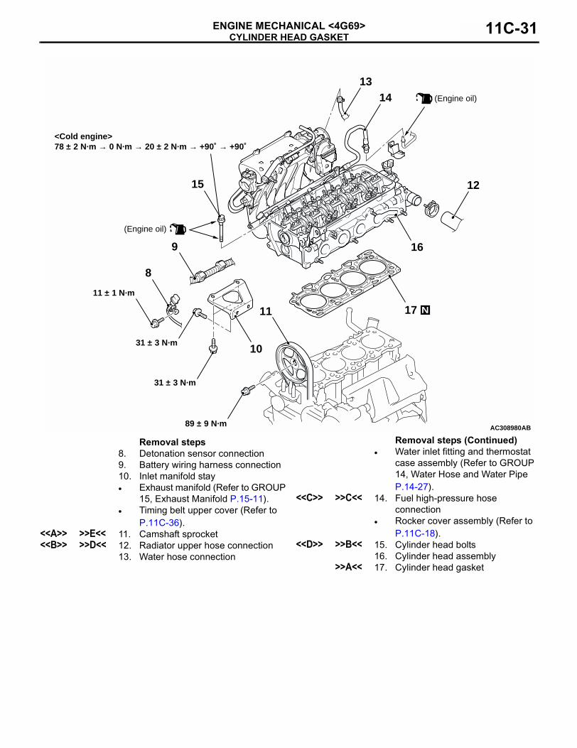
CYLINDER HEAD GASKETENGINE MECHANICAL <4G69> 11C-31
AC308980AB
<Cold engine>78 ± 2 N·m → 0 N·m → 20 ± 2 N·m → +90˚ → +90˚
17
16
15
1413
12
10
9
8
11 N
89 ± 9 N·m
11 ± 1 N·m
31 ± 3 N·m
31 ± 3 N·m
(Engine oil)
(Engine oil)
Removal steps8. Detonation sensor connection9. Battery wiring harness connection 10. Inlet manifold stay• Exhaust manifold (Refer to GROUP
15, Exhaust Manifold P.15-11).• Timing belt upper cover (Refer to
P.11C-36).<<A>> >>E<< 11. Camshaft sprocket<<B>> >>D<< 12. Radiator upper hose connection
13. Water hose connection
• Water inlet fitting and thermostat case assembly (Refer to GROUP 14, Water Hose and Water Pipe P.14-27).
<<C>> >>C<< 14. Fuel high-pressure hose connection
• Rocker cover assembly (Refer to P.11C-18).
<<D>> >>B<< 15. Cylinder head bolts16. Cylinder head assembly
>>A<< 17. Cylinder head gasket
Removal steps (Continued)
CYLINDER HEAD GASKETENGINE MECHANICAL <4G69>11C-32
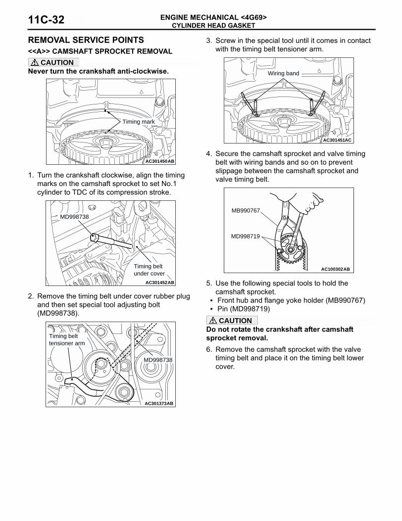
REMOVAL SERVICE POINTS<<A>> CAMSHAFT SPROCKET REMOVAL
CAUTIONNever turn the crankshaft anti-clockwise.
1. Turn the crankshaft clockwise, align the timing marks on the camshaft sprocket to set No.1 cylinder to TDC of its compression stroke.
2. Remove the timing belt under cover rubber plug and then set special tool adjusting bolt (MD998738).
3. Screw in the special tool until it comes in contact with the timing belt tensioner arm.
4. Secure the camshaft sprocket and valve timing belt with wiring bands and so on to prevent slippage between the camshaft sprocket and valve timing belt.
5. Use the following special tools to hold the camshaft sprocket.
• Front hub and flange yoke holder (MB990767)• Pin (MD998719)
CAUTIONDo not rotate the crankshaft after camshaft sprocket removal.6. Remove the camshaft sprocket with the valve
timing belt and place it on the timing belt lower cover.
AC301450AB
Timing mark
AC301452AB
MD998738
Timing beltunder cover
AC301373AB
MD998738
Timing belttensioner arm
AC107621
AC301451AC
Wiring band
AC100302
MD998719
MB990767
AB
CYLINDER HEAD GASKETENGINE MECHANICAL <4G69> 11C-33
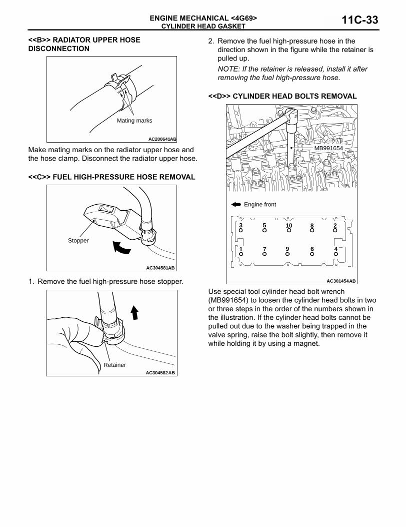
<<B>> RADIATOR UPPER HOSE DISCONNECTION
Make mating marks on the radiator upper hose and the hose clamp. Disconnect the radiator upper hose.
<<C>> FUEL HIGH-PRESSURE HOSE REMOVAL
1. Remove the fuel high-pressure hose stopper.
2. Remove the fuel high-pressure hose in the direction shown in the figure while the retainer is pulled up. NOTE: If the retainer is released, install it after removing the fuel high-pressure hose.
<<D>> CYLINDER HEAD BOLTS REMOVAL
Use special tool cylinder head bolt wrench (MB991654) to loosen the cylinder head bolts in two or three steps in the order of the numbers shown in the illustration. If the cylinder head bolts cannot be pulled out due to the washer being trapped in the valve spring, raise the bolt slightly, then remove it while holding it by using a magnet.
AC200641AB
Mating marks
AC304581AB
Stopper
AC304582AB
Retainer
AC301454AB
MB991654
105 283
97 461
Engine front
CYLINDER HEAD GASKETENGINE MECHANICAL <4G69>11C-34
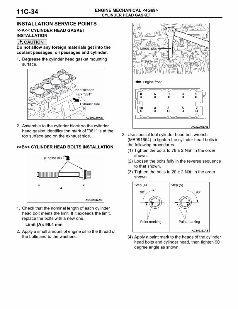
INSTALLATION SERVICE POINTS>>A<< CYLINDER HEAD GASKET INSTALLATION
CAUTIONDo not allow any foreign materials get into the coolant passages, oil passages and cylinder.1. Degrease the cylinder head gasket mounting
surface.
2. Assemble to the cylinder block so the cylinder head gasket identification mark of "381" is at the top surface and on the exhaust side.
>>B<< CYLINDER HEAD BOLTS INSTALLATION
1. Check that the nominal length of each cylinder head bolt meets the limit. If it exceeds the limit, replace the bolts with a new one.
Limit (A): 99.4 mm2. Apply a small amount of engine oil to the thread of
the bolts and to the washers.
3. Use special tool cylinder head bolt wrench (MB991654) to tighten the cylinder head bolts in the following procedures.(1) Tighten the bolts to 78 ± 2 N⋅m in the order
shown.(2) Loosen the bolts fully in the reverse sequence
to that shown.(3) Tighten the bolts to 20 ± 2 N⋅m in the order
shown.
(4) Apply a paint mark to the heads of the cylinder head bolts and cylinder head, then tighten 90 degree angle as shown.
AC302180AB
Identificationmark "381"
Exhaust side
AC102537
A
AC
(Engine oil)
AC301456AB
MB991654
10
9
7524
8 6 1 3
Engine front
AC102331AB
Paint marking
90˚ 90˚
Step (4) Step (5)
Paint marking
CYLINDER HEAD GASKETENGINE MECHANICAL <4G69> 11C-35
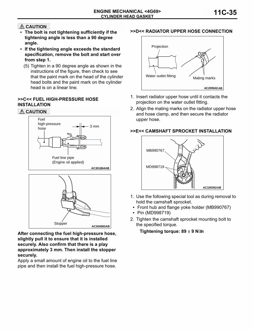
CAUTION• The bolt is not tightening sufficiently if the
tightening angle is less than a 90 degree angle.
• If the tightening angle exceeds the standard specification, remove the bolt and start over from step 1.(5) Tighten in a 90 degree angle as shown in the
instructions of the figure, then check to see that the paint mark on the head of the cylinder head bolts and the paint mark on the cylinder head is on a linear line.
>>C<< FUEL HIGH-PRESSURE HOSE INSTALLATION
CAUTION
After connecting the fuel high-pressure hose, slightly pull it to ensure that it is installed securely. Also confirm that there is a play approximately 3 mm. Then install the stopper securely.Apply a small amount of engine oil to the fuel line pipe and then install the fuel high-pressure hose.
>>D<< RADIATOR UPPER HOSE CONNECTION
1. Insert radiator upper hose until it contacts the projection on the water outlet fitting.
2. Align the mating marks on the radiator upper hose and hose clamp, and then secure the radiator upper hose.
>>E<< CAMSHAFT SPROCKET INSTALLATION
1. Use the following special tool as during removal to hold the camshaft sprocket.
• Front hub and flange yoke holder (MB990767)• Pin (MD998719)
2. Tighten the camshaft sprocket mounting bolt to the specified torque.
Tightening torque: 89 ± 9 N⋅m
AC301864AB
3 mm
Fuel high-pressure hose
Fuel line pipe(Engine oil applied)
AC304583ABStopper
AC200642
Mating marks
Projection
Water outlet fitting
AB
AC100302
MD998719
MB990767
AB
TIMING BELTENGINE MECHANICAL <4G69>11C-36
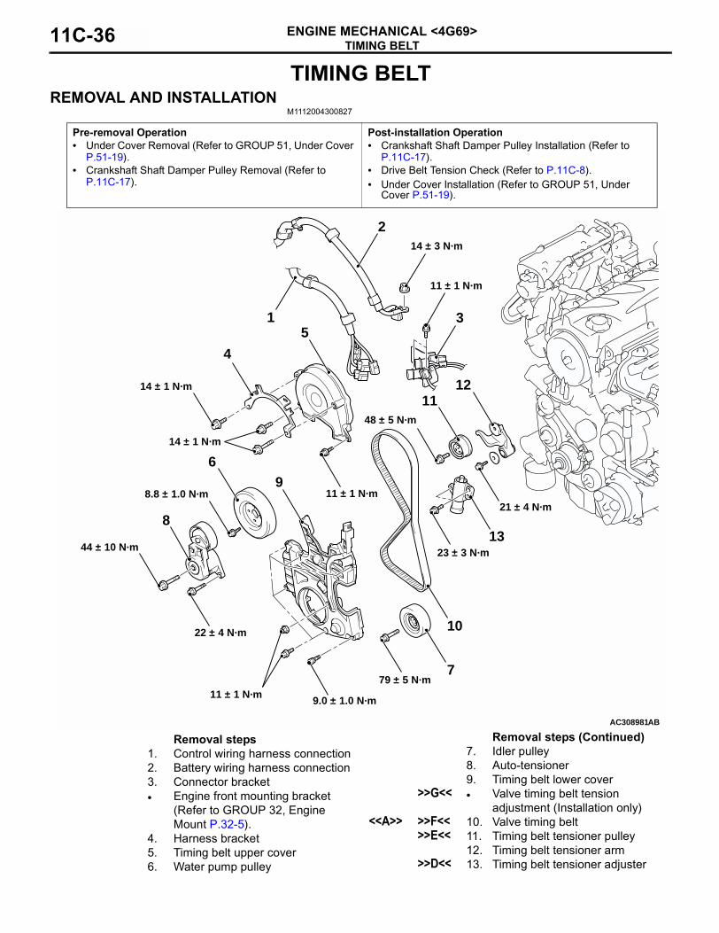
TIMING BELTREMOVAL AND INSTALLATION
M1112004300827
Pre-removal Operation• Under Cover Removal (Refer to GROUP 51, Under Cover
P.51-19).• Crankshaft Shaft Damper Pulley Removal (Refer to
P.11C-17).
Post-installation Operation• Crankshaft Shaft Damper Pulley Installation (Refer to
P.11C-17).• Drive Belt Tension Check (Refer to P.11C-8).• Under Cover Installation (Refer to GROUP 51, Under
Cover P.51-19).
AC308981AB
14 ± 1 N·m
1
13
12
10
9
8
7
6
5
11
4
3
2
14 ± 1 N·m
8.8 ± 1.0 N·m
44 ± 10 N·m
22 ± 4 N·m
11 ± 1 N·m9.0 ± 1.0 N·m
11 ± 1 N·m
79 ± 5 N·m
11 ± 1 N·m
21 ± 4 N·m
48 ± 5 N·m
23 ± 3 N·m
14 ± 3 N·m
Removal steps1. Control wiring harness connection 2. Battery wiring harness connection 3. Connector bracket• Engine front mounting bracket
(Refer to GROUP 32, Engine Mount P.32-5).
4. Harness bracket5. Timing belt upper cover6. Water pump pulley
7. Idler pulley8. Auto-tensioner9. Timing belt lower cover
>>G<< • Valve timing belt tension adjustment (Installation only)
<<A>> >>F<< 10. Valve timing belt >>E<< 11. Timing belt tensioner pulley
12. Timing belt tensioner arm>>D<< 13. Timing belt tensioner adjuster
Removal steps (Continued)
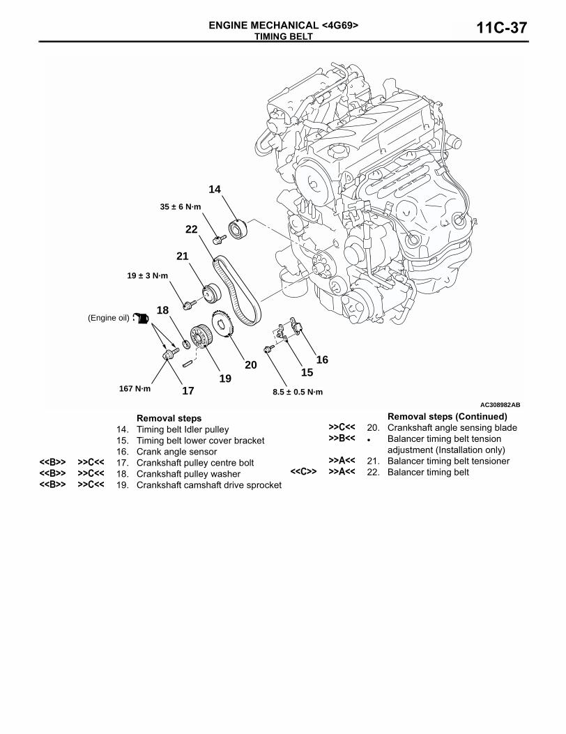
TIMING BELTENGINE MECHANICAL <4G69> 11C-37
AC308982
19
18
17
1615
14
22
20
21
(Engine oil)
35 ± 6 N·m
8.5 ± 0.5 N·m
19 ± 3 N·m
167 N·m
AB
Removal steps14. Timing belt Idler pulley15. Timing belt lower cover bracket16. Crank angle sensor
<<B>> >>C<< 17. Crankshaft pulley centre bolt<<B>> >>C<< 18. Crankshaft pulley washer<<B>> >>C<< 19. Crankshaft camshaft drive sprocket
>>C<< 20. Crankshaft angle sensing blade>>B<< • Balancer timing belt tension
adjustment (Installation only)>>A<< 21. Balancer timing belt tensioner
<<C>> >>A<< 22. Balancer timing belt
Removal steps (Continued)
TIMING BELTENGINE MECHANICAL <4G69>11C-38
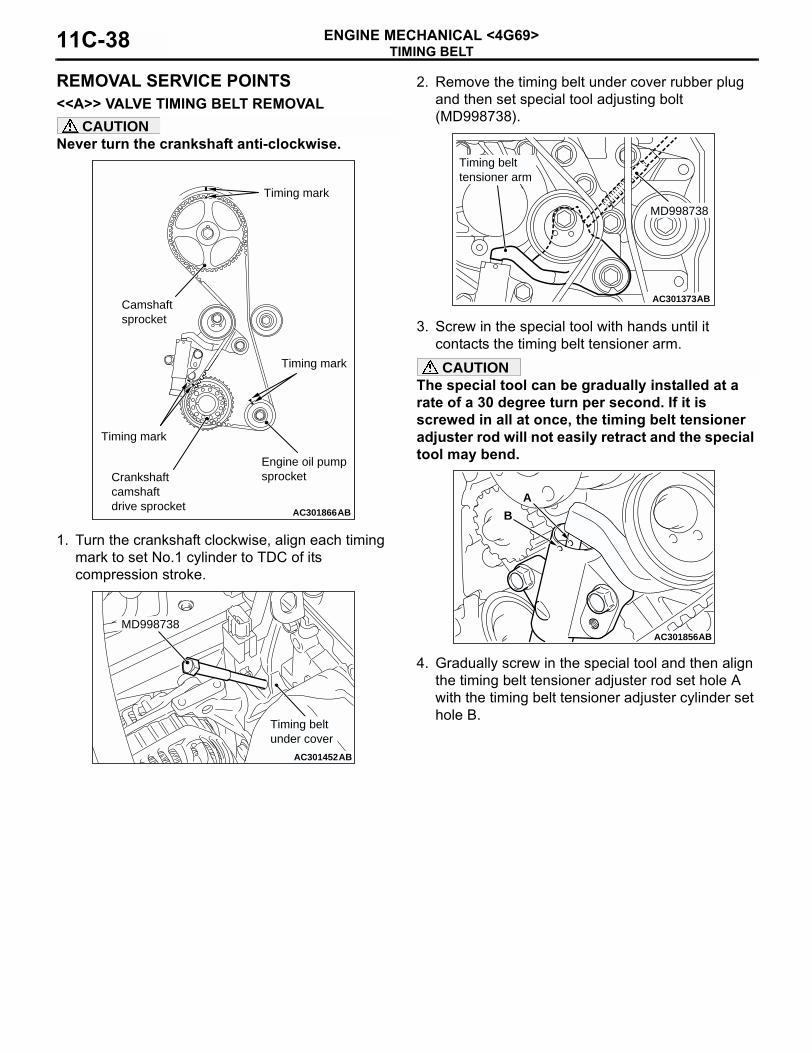
REMOVAL SERVICE POINTS<<A>> VALVE TIMING BELT REMOVAL
CAUTIONNever turn the crankshaft anti-clockwise.
1. Turn the crankshaft clockwise, align each timing mark to set No.1 cylinder to TDC of its compression stroke.
2. Remove the timing belt under cover rubber plug and then set special tool adjusting bolt (MD998738).
3. Screw in the special tool with hands until it contacts the timing belt tensioner arm.CAUTION
The special tool can be gradually installed at a rate of a 30 degree turn per second. If it is screwed in all at once, the timing belt tensioner adjuster rod will not easily retract and the special tool may bend.
4. Gradually screw in the special tool and then align the timing belt tensioner adjuster rod set hole A with the timing belt tensioner adjuster cylinder set hole B.
AC301866AB
Timing mark
Crankshaftcamshaftdrive sprocket
Camshaftsprocket
Timing mark
Timing mark
Engine oil pump sprocket
AC301452AB
MD998738
Timing beltunder cover
AC301373AB
MD998738
Timing belttensioner arm
AC301856
A
B
AB
TIMING BELTENGINE MECHANICAL <4G69> 11C-39
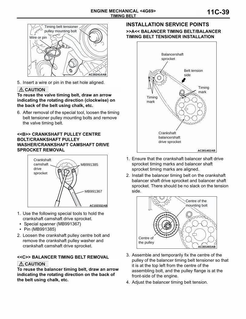
5. Insert a wire or pin in the set hole aligned.CAUTION
To reuse the valve timing belt, draw an arrow indicating the rotating direction (clockwise) on the back of the belt using chalk, etc.6. After removal of the special tool, loosen the timing
belt tensioner pulley mounting bolts and remove the valve timing belt.
<<B>> CRANKSHAFT PULLEY CENTRE BOLT/CRANKSHAFT PULLEY WASHER/CRANKSHAFT CAMSHAFT DRIVE SPROCKET REMOVAL
1. Use the following special tools to hold the crankshaft camshaft drive sprocket.
• Special spanner (MB991367)• Pin (MB991385)
2. Loosen the crankshaft pulley centre bolt and remove the crankshaft pulley washer and crankshaft camshaft drive sprocket.
<<C>> BALANCER TIMING BELT REMOVALCAUTION
To reuse the balancer timing belt, draw an arrow indicating the rotating direction on the back of the belt using chalk, etc.
INSTALLATION SERVICE POINTS>>A<< BALANCER TIMING BELT/BALANCER TIMING BELT TENSIONER INSTALLATION
1. Ensure that the crankshaft balancer shaft drive sprocket timing marks and balancer shaft sprocket timing marks are aligned.
2. Install the balancer timing belt on the crankshaft balancer shaft drive sprocket and balancer shaft sprocket. There should be no slack on the tension side.
3. Assemble and temporarily fix the centre of the pulley of the balancer timing belt tensioner so that it is at the top left from the centre of the assembling bolt, and the pulley flange is at the front-side of the engine.
4. Adjust the balancer timing belt tension.
AC302414AB
Timing belt tensioner pulley mounting bolt
Wire or pin
AC102332AB
MB991385
MB991367
Crankshaftcamshaftdrive sprocket
AC301402AB
Balancershaft sprocket
Belt tension side
Timing mark
Crankshaftbalancershaftdrive sprocket
Timing mark
AC301403AB
Centre ofthe pulley
Centre of the mounting bolt
TIMING BELTENGINE MECHANICAL <4G69>11C-40
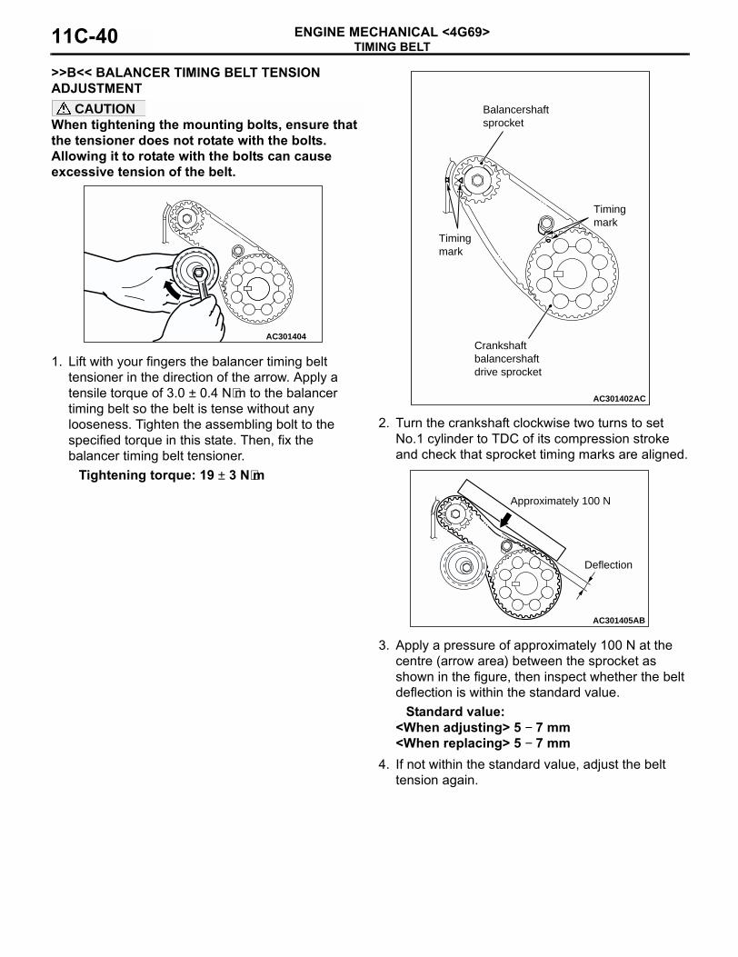
>>B<< BALANCER TIMING BELT TENSION ADJUSTMENT
CAUTIONWhen tightening the mounting bolts, ensure that the tensioner does not rotate with the bolts. Allowing it to rotate with the bolts can cause excessive tension of the belt.
1. Lift with your fingers the balancer timing belt tensioner in the direction of the arrow. Apply a tensile torque of 3.0 ± 0.4 N⋅m to the balancer timing belt so the belt is tense without any looseness. Tighten the assembling bolt to the specified torque in this state. Then, fix the balancer timing belt tensioner.
Tightening torque: 19 ± 3 N⋅m
2. Turn the crankshaft clockwise two turns to set No.1 cylinder to TDC of its compression stroke and check that sprocket timing marks are aligned.
3. Apply a pressure of approximately 100 N at the centre (arrow area) between the sprocket as shown in the figure, then inspect whether the belt deflection is within the standard value.
Standard value:<When adjusting> 5 − 7 mm<When replacing> 5 − 7 mm
4. If not within the standard value, adjust the belt tension again.
AC301404
AC301402AC
Balancershaft sprocket
Timing mark
Crankshaftbalancershaftdrive sprocket
Timing mark
AC301405AB
Deflection
Approximately 100 N
TIMING BELTENGINE MECHANICAL <4G69> 11C-41
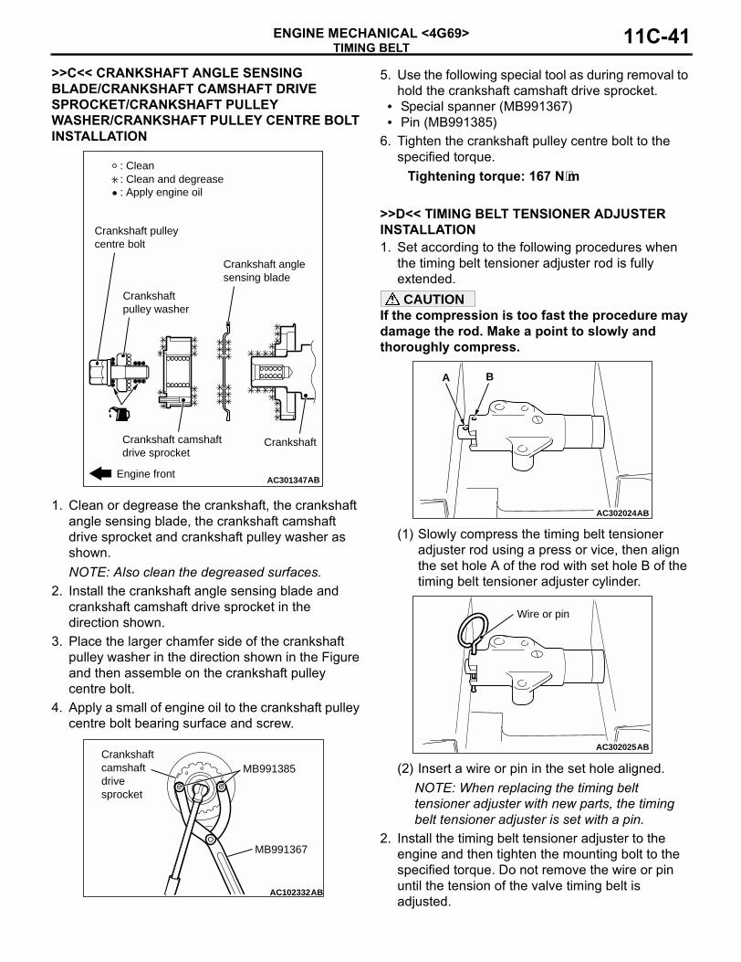
>>C<< CRANKSHAFT ANGLE SENSING BLADE/CRANKSHAFT CAMSHAFT DRIVE SPROCKET/CRANKSHAFT PULLEY WASHER/CRANKSHAFT PULLEY CENTRE BOLT INSTALLATION
1. Clean or degrease the crankshaft, the crankshaft angle sensing blade, the crankshaft camshaft drive sprocket and crankshaft pulley washer as shown.NOTE: Also clean the degreased surfaces.
2. Install the crankshaft angle sensing blade and crankshaft camshaft drive sprocket in the direction shown.
3. Place the larger chamfer side of the crankshaft pulley washer in the direction shown in the Figure and then assemble on the crankshaft pulley centre bolt.
4. Apply a small of engine oil to the crankshaft pulley centre bolt bearing surface and screw.
5. Use the following special tool as during removal to hold the crankshaft camshaft drive sprocket.
• Special spanner (MB991367)• Pin (MB991385)
6. Tighten the crankshaft pulley centre bolt to the specified torque.
Tightening torque: 167 N⋅m
>>D<< TIMING BELT TENSIONER ADJUSTER INSTALLATION1. Set according to the following procedures when
the timing belt tensioner adjuster rod is fully extended.CAUTION
If the compression is too fast the procedure may damage the rod. Make a point to slowly and thoroughly compress.
(1) Slowly compress the timing belt tensioner adjuster rod using a press or vice, then align the set hole A of the rod with set hole B of the timing belt tensioner adjuster cylinder.
(2) Insert a wire or pin in the set hole aligned.NOTE: When replacing the timing belt tensioner adjuster with new parts, the timing belt tensioner adjuster is set with a pin.
2. Install the timing belt tensioner adjuster to the engine and then tighten the mounting bolt to the specified torque. Do not remove the wire or pin until the tension of the valve timing belt is adjusted.
AC301347AB
: Clean
: Apply engine oil: Clean and degrease
Crankshaft camshaft drive sprocket
Crankshaft pulley centre bolt
Crankshaft
Crankshaft angle sensing blade
Crankshaft pulley washer
Engine front
AC102332AB
MB991385
MB991367
Crankshaftcamshaftdrive sprocket
AC302024
A
AB
B
AC302025AB
Wire or pin
TIMING BELTENGINE MECHANICAL <4G69>11C-42
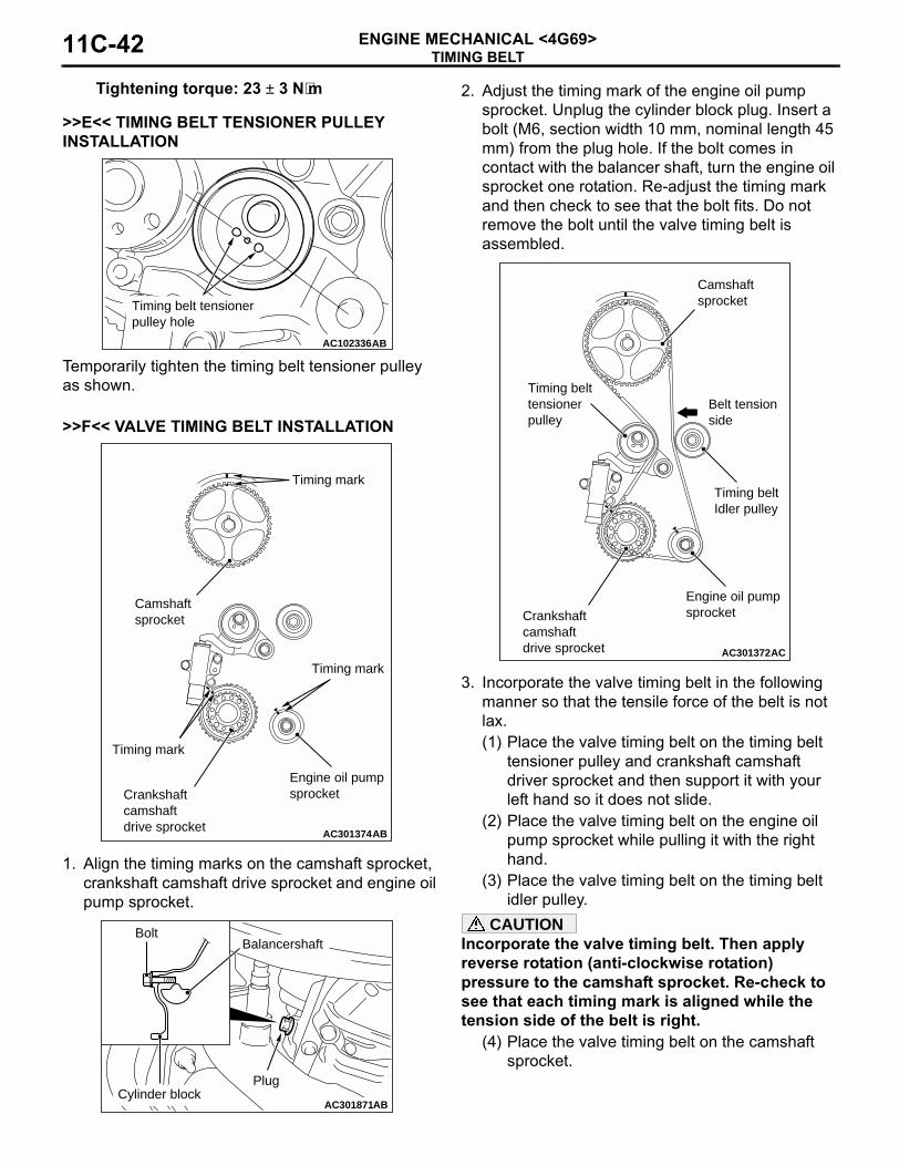
Tightening torque: 23 ± 3 N⋅m
>>E<< TIMING BELT TENSIONER PULLEY INSTALLATION
Temporarily tighten the timing belt tensioner pulley as shown.
>>F<< VALVE TIMING BELT INSTALLATION
1. Align the timing marks on the camshaft sprocket, crankshaft camshaft drive sprocket and engine oil pump sprocket.
2. Adjust the timing mark of the engine oil pump sprocket. Unplug the cylinder block plug. Insert a bolt (M6, section width 10 mm, nominal length 45 mm) from the plug hole. If the bolt comes in contact with the balancer shaft, turn the engine oil sprocket one rotation. Re-adjust the timing mark and then check to see that the bolt fits. Do not remove the bolt until the valve timing belt is assembled.
3. Incorporate the valve timing belt in the following manner so that the tensile force of the belt is not lax. (1) Place the valve timing belt on the timing belt
tensioner pulley and crankshaft camshaft driver sprocket and then support it with your left hand so it does not slide.
(2) Place the valve timing belt on the engine oil pump sprocket while pulling it with the right hand.
(3) Place the valve timing belt on the timing belt idler pulley.
CAUTIONIncorporate the valve timing belt. Then apply reverse rotation (anti-clockwise rotation) pressure to the camshaft sprocket. Re-check to see that each timing mark is aligned while the tension side of the belt is right.
(4) Place the valve timing belt on the camshaft sprocket.
AC102336AB
Timing belt tensionerpulley hole
AC301374AB
Timing mark
Crankshaftcamshaftdrive sprocket
Camshaftsprocket
Timing mark
Timing mark
Engine oil pump sprocket
AC301871AB
Bolt
PlugCylinder block
Balancershaft
AC301372AC
Crankshaftcamshaftdrive sprocket
Camshaftsprocket
Engine oil pump sprocket
Timing belt tensionerpulley
Timing belt Idler pulley
Belt tension side
TIMING BELTENGINE MECHANICAL <4G69> 11C-43
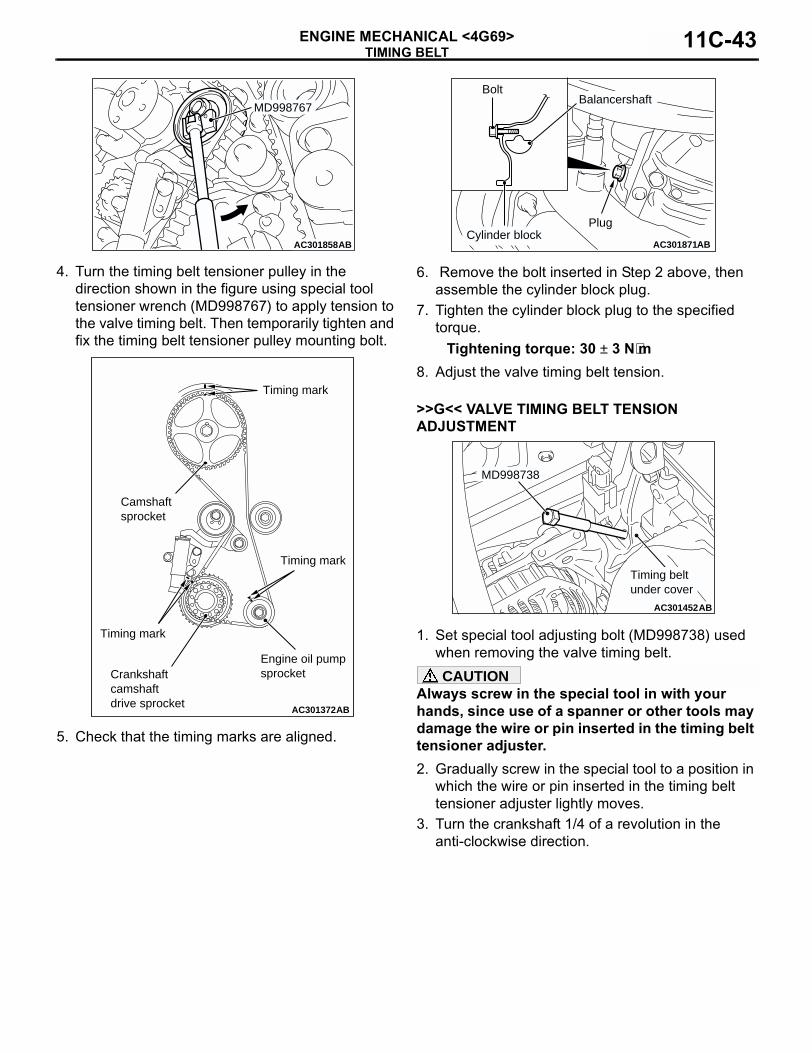
4. Turn the timing belt tensioner pulley in the direction shown in the figure using special tool tensioner wrench (MD998767) to apply tension to the valve timing belt. Then temporarily tighten and fix the timing belt tensioner pulley mounting bolt.
5. Check that the timing marks are aligned.
6. Remove the bolt inserted in Step 2 above, then assemble the cylinder block plug.
7. Tighten the cylinder block plug to the specified torque.
Tightening torque: 30 ± 3 N⋅m8. Adjust the valve timing belt tension.
>>G<< VALVE TIMING BELT TENSION ADJUSTMENT
1. Set special tool adjusting bolt (MD998738) used when removing the valve timing belt.CAUTION
Always screw in the special tool in with your hands, since use of a spanner or other tools may damage the wire or pin inserted in the timing belt tensioner adjuster. 2. Gradually screw in the special tool to a position in
which the wire or pin inserted in the timing belt tensioner adjuster lightly moves.
3. Turn the crankshaft 1/4 of a revolution in the anti-clockwise direction.
AC301858
MD998767
AB
AC301372AB
Timing mark
Crankshaftcamshaftdrive sprocket
Camshaftsprocket
Timing mark
Timing mark
Engine oil pump sprocket
AC301871AB
Bolt
PlugCylinder block
Balancershaft
AC301452AB
MD998738
Timing beltunder cover
TIMING BELTENGINE MECHANICAL <4G69>11C-44
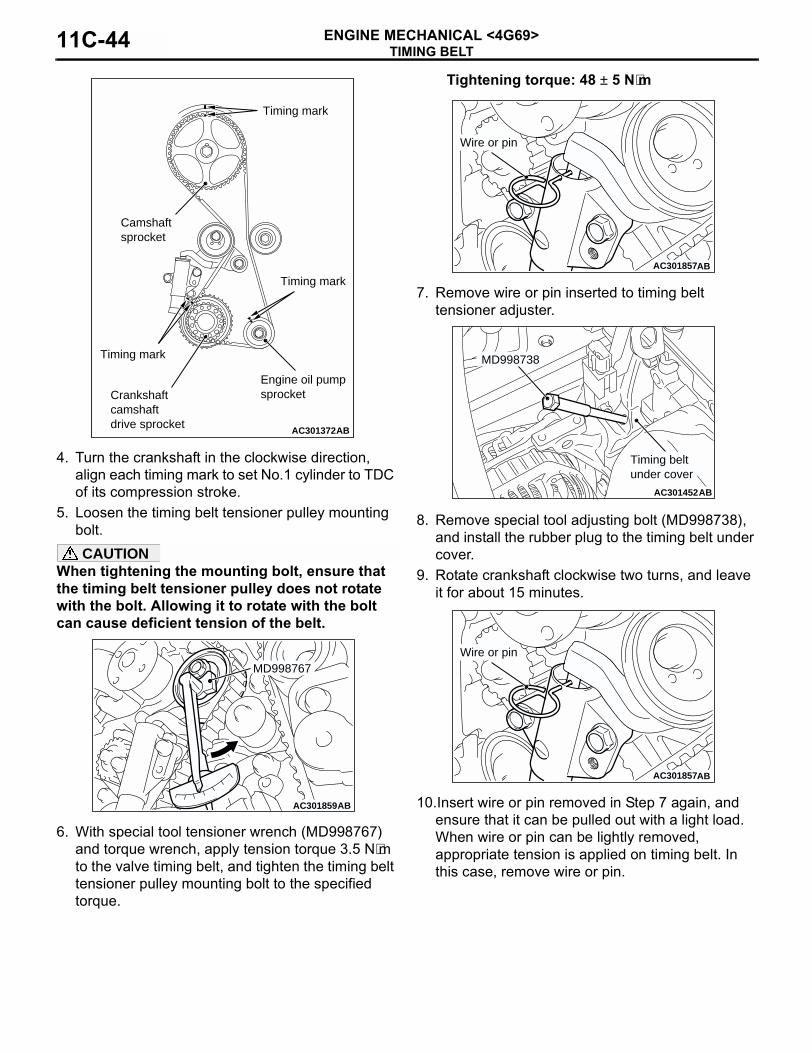
4. Turn the crankshaft in the clockwise direction, align each timing mark to set No.1 cylinder to TDC of its compression stroke.
5. Loosen the timing belt tensioner pulley mounting bolt.CAUTION
When tightening the mounting bolt, ensure that the timing belt tensioner pulley does not rotate with the bolt. Allowing it to rotate with the bolt can cause deficient tension of the belt.
6. With special tool tensioner wrench (MD998767) and torque wrench, apply tension torque 3.5 N⋅m to the valve timing belt, and tighten the timing belt tensioner pulley mounting bolt to the specified torque.
Tightening torque: 48 ± 5 N⋅m
7. Remove wire or pin inserted to timing belt tensioner adjuster.
8. Remove special tool adjusting bolt (MD998738), and install the rubber plug to the timing belt under cover.
9. Rotate crankshaft clockwise two turns, and leave it for about 15 minutes.
10.Insert wire or pin removed in Step 7 again, and ensure that it can be pulled out with a light load. When wire or pin can be lightly removed, appropriate tension is applied on timing belt. In this case, remove wire or pin.
AC301372AB
Timing mark
Crankshaftcamshaftdrive sprocket
Camshaftsprocket
Timing mark
Timing mark
Engine oil pump sprocket
AC301859
MD998767
AB
AC301857AB
Wire or pin
AC301452AB
MD998738
Timing beltunder cover
AC301857AB
Wire or pin
TIMING BELTENGINE MECHANICAL <4G69> 11C-45
Also the projection of timing belt tensioner adjuster rod (A) is within the standard value, appropriate tension is applied.
Standard value (A): 3.8 − 4.5 mm11.If wire or pin cannot be easily pulled out, repeat
Step 1 through Step 9 to reach proper valve timing belt tension.CAUTION
Always check the tightening torque of the crankshaft pulley centre bolt when turning the crankshaft pulley centre bolt anti-clockwise. Re-tighten if it is loose.
12.Check again that the timing marks on sprockets are aligned.
INSPECTIONM1112004400460
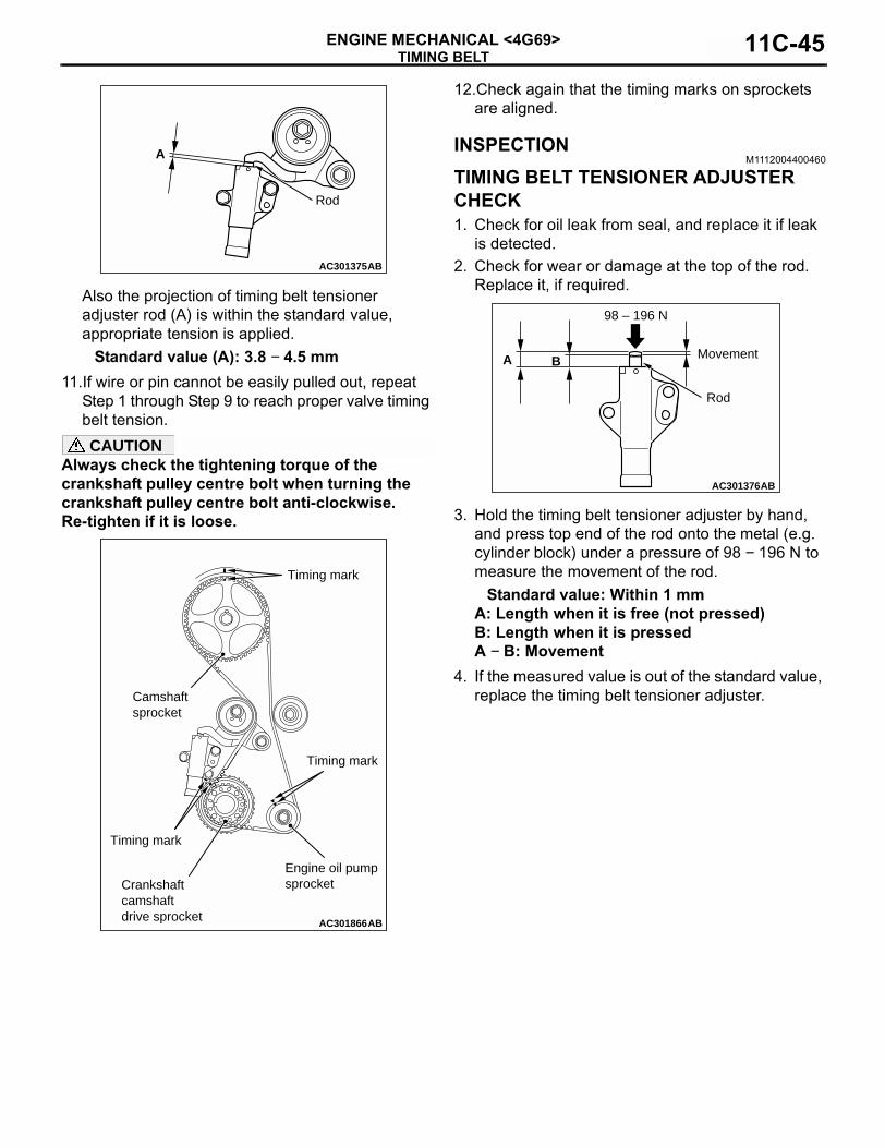
TIMING BELT TENSIONER ADJUSTER CHECK1. Check for oil leak from seal, and replace it if leak
is detected.2. Check for wear or damage at the top of the rod.
Replace it, if required.
3. Hold the timing belt tensioner adjuster by hand, and press top end of the rod onto the metal (e.g. cylinder block) under a pressure of 98 − 196 N to measure the movement of the rod.
Standard value: Within 1 mmA: Length when it is free (not pressed)B: Length when it is pressedA − B: Movement
4. If the measured value is out of the standard value, replace the timing belt tensioner adjuster.
AC301375AB
A
Rod
AC301866AB
Timing mark
Crankshaftcamshaftdrive sprocket
Camshaftsprocket
Timing mark
Timing mark
Engine oil pump sprocket
AC301376AB
A B
98 – 196 N
Rod
Movement
TIMING BELTENGINE MECHANICAL <4G69>11C-46
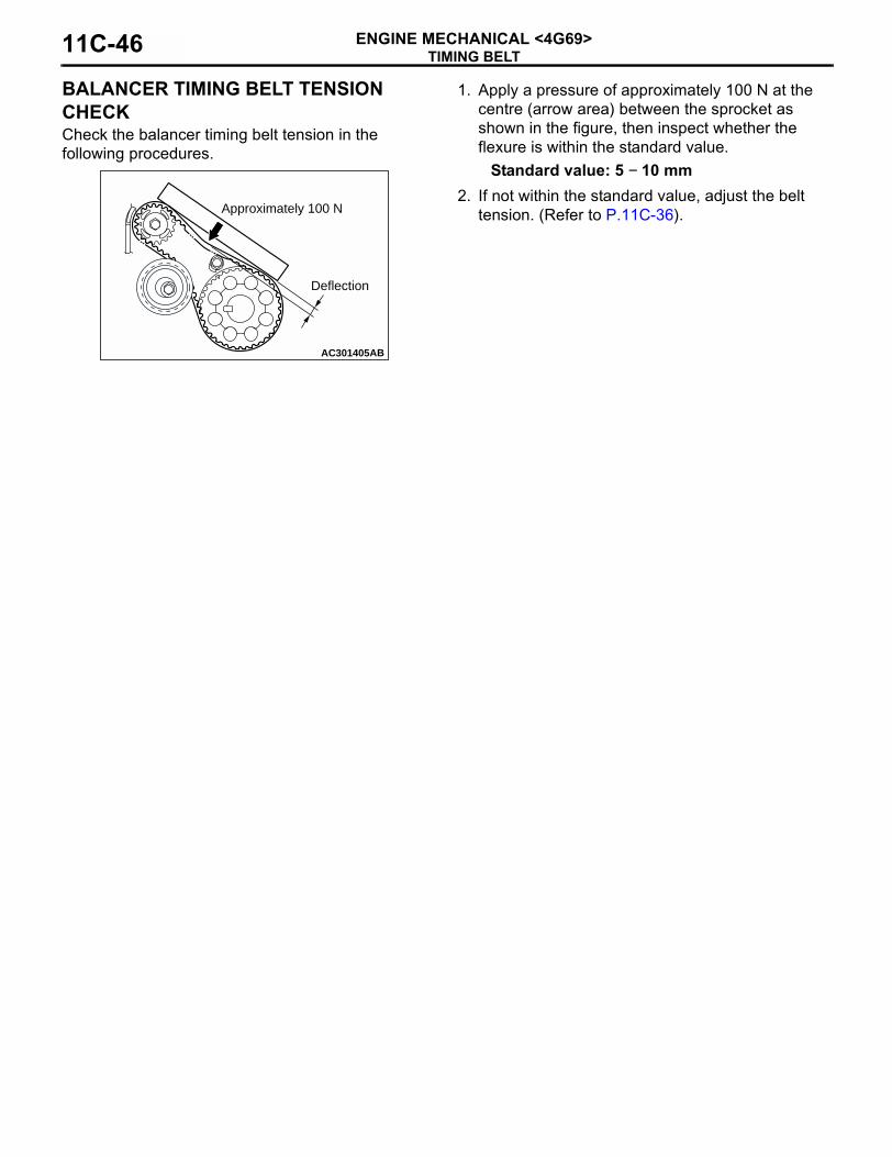
BALANCER TIMING BELT TENSION CHECK Check the balancer timing belt tension in the following procedures.
1. Apply a pressure of approximately 100 N at the centre (arrow area) between the sprocket as shown in the figure, then inspect whether the flexure is within the standard value.
Standard value: 5 − 10 mm2. If not within the standard value, adjust the belt
tension. (Refer to P.11C-36).
AC301405AB
Deflection
Approximately 100 N
ENGINE ASSEMBLYENGINE MECHANICAL <4G69> 11C-47
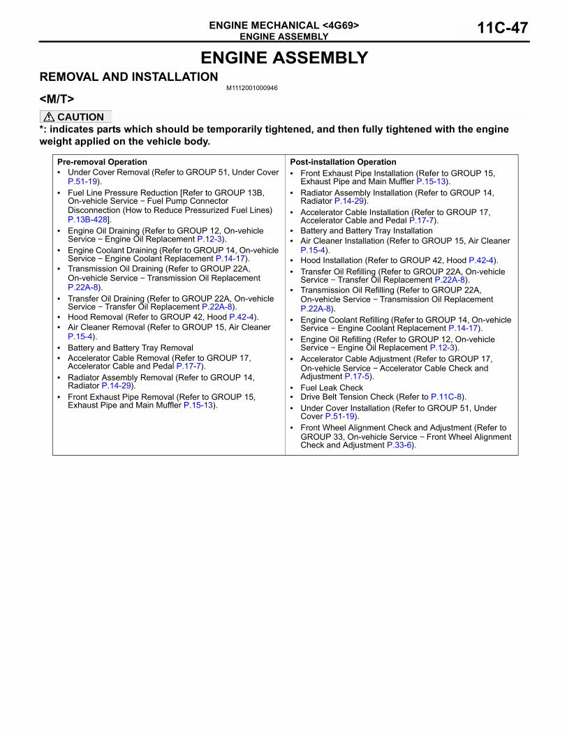
ENGINE ASSEMBLYREMOVAL AND INSTALLATION
M1112001000946
<M/T>CAUTION
*: indicates parts which should be temporarily tightened, and then fully tightened with the engine weight applied on the vehicle body.
Pre-removal Operation• Under Cover Removal (Refer to GROUP 51, Under Cover
P.51-19).• Fuel Line Pressure Reduction [Refer to GROUP 13B,
On-vehicle Service − Fuel Pump Connector Disconnection (How to Reduce Pressurized Fuel Lines) P.13B-428].
• Engine Oil Draining (Refer to GROUP 12, On-vehicle Service − Engine Oil Replacement P.12-3).
• Engine Coolant Draining (Refer to GROUP 14, On-vehicle Service − Engine Coolant Replacement P.14-17).
• Transmission Oil Draining (Refer to GROUP 22A, On-vehicle Service − Transmission Oil Replacement P.22A-8).
• Transfer Oil Draining (Refer to GROUP 22A, On-vehicle Service − Transfer Oil Replacement P.22A-8).
• Hood Removal (Refer to GROUP 42, Hood P.42-4).• Air Cleaner Removal (Refer to GROUP 15, Air Cleaner
P.15-4).• Battery and Battery Tray Removal• Accelerator Cable Removal (Refer to GROUP 17,
Accelerator Cable and Pedal P.17-7).• Radiator Assembly Removal (Refer to GROUP 14,
Radiator P.14-29).• Front Exhaust Pipe Removal (Refer to GROUP 15,
Exhaust Pipe and Main Muffler P.15-13).
Post-installation Operation• Front Exhaust Pipe Installation (Refer to GROUP 15,
Exhaust Pipe and Main Muffler P.15-13).• Radiator Assembly Installation (Refer to GROUP 14,
Radiator P.14-29).• Accelerator Cable Installation (Refer to GROUP 17,
Accelerator Cable and Pedal P.17-7).• Battery and Battery Tray Installation• Air Cleaner Installation (Refer to GROUP 15, Air Cleaner
P.15-4).• Hood Installation (Refer to GROUP 42, Hood P.42-4).• Transfer Oil Refilling (Refer to GROUP 22A, On-vehicle
Service − Transfer Oil Replacement P.22A-8).• Transmission Oil Refilling (Refer to GROUP 22A,
On-vehicle Service − Transmission Oil Replacement P.22A-8).
• Engine Coolant Refilling (Refer to GROUP 14, On-vehicle Service − Engine Coolant Replacement P.14-17).
• Engine Oil Refilling (Refer to GROUP 12, On-vehicle Service − Engine Oil Replacement P.12-3).
• Accelerator Cable Adjustment (Refer to GROUP 17, On-vehicle Service − Accelerator Cable Check and Adjustment P.17-5).
• Fuel Leak Check• Drive Belt Tension Check (Refer to P.11C-8).• Under Cover Installation (Refer to GROUP 51, Under
Cover P.51-19).• Front Wheel Alignment Check and Adjustment (Refer to
GROUP 33, On-vehicle Service − Front Wheel Alignment Check and Adjustment P.33-6).
ENGINE ASSEMBLYENGINE MECHANICAL <4G69>11C-48
AC308983
7
66N N
48 ± 7 N·m
48 ± 7 N·m
12 ± 2 N·m
5.0 ± 1.0 N·m
5.0 ± 1.0 N·m
9.0 ± 2.0 N·m
9.0 ± 2.0 N·m
9.0 ± 2.0 N·m
1
5
43
2
AB
6N
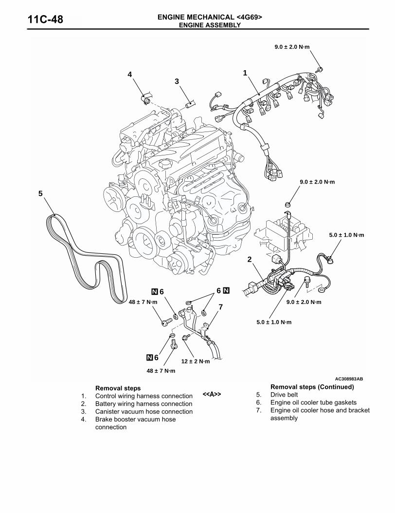
Removal steps1. Control wiring harness connection 2. Battery wiring harness connection 3. Canister vacuum hose connection4. Brake booster vacuum hose
connection
<<A>> 5. Drive belt6. Engine oil cooler tube gaskets7. Engine oil cooler hose and bracket
assembly
Removal steps (Continued)
ENGINE ASSEMBLYENGINE MECHANICAL <4G69> 11C-49
AC308984
44 ± 10 N·m*
44 ± 10 N·m*
13
14
N
12
22 ± 4 N·m
AB
(Engine oil)
15
1110
9
824 ± 4 N·m
44 ± 10 N·m
70 ± 4 N·m*
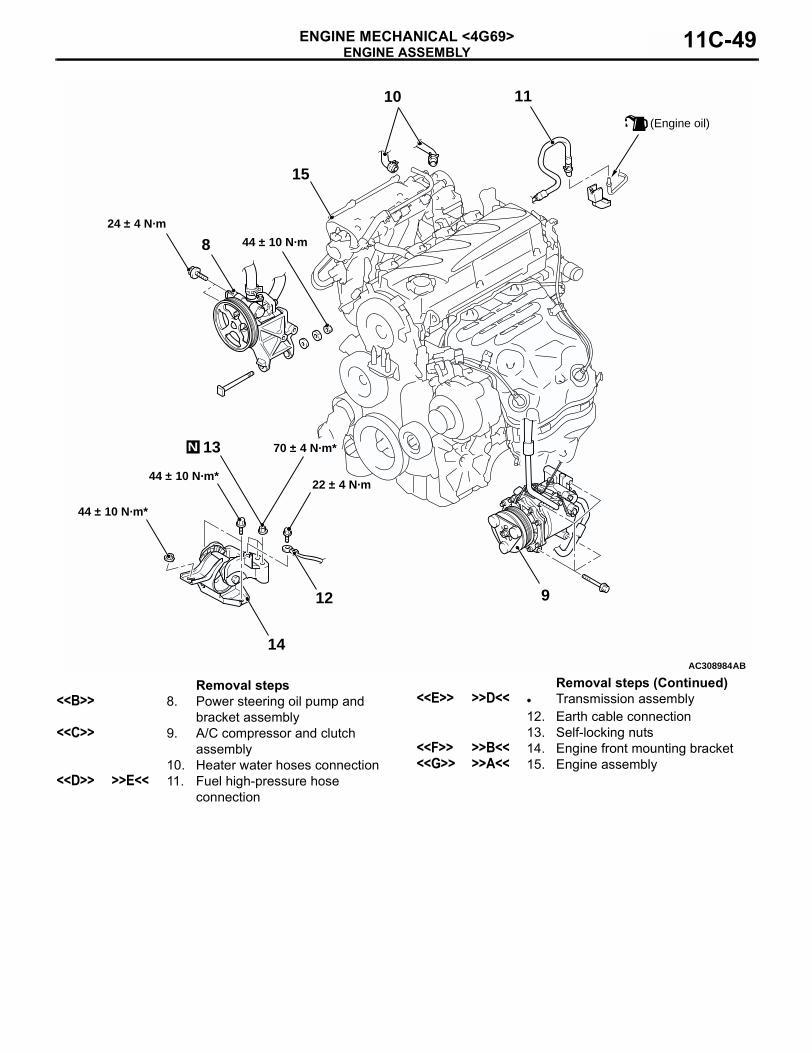
Removal steps<<B>> 8. Power steering oil pump and
bracket assembly<<C>> 9. A/C compressor and clutch
assembly10. Heater water hoses connection
<<D>> >>E<< 11. Fuel high-pressure hose connection
<<E>> >>D<< • Transmission assembly12. Earth cable connection13. Self-locking nuts
<<F>> >>B<< 14. Engine front mounting bracket<<G>> >>A<< 15. Engine assembly
Removal steps (Continued)
ENGINE ASSEMBLYENGINE MECHANICAL <4G69>11C-50
<A/T>CAUTION
*: indicates parts which should be temporarily tightened, and then fully tightened with the engine weight applied on the vehicle body.
Pre-removal Operation• Under Cover Removal (Refer to GROUP 51, Under Cover
P.51-19).• Fuel Line Pressure Reduction [Refer to GROUP 13B,
On-vehicle Service − Fuel Pump Connector Disconnection (How to Reduce Pressurized Fuel Lines) P.13B-428].
• Engine Oil Draining (Refer to GROUP 12, On-vehicle Service − Engine Oil Replacement P.12-3).
• Engine Coolant Draining (Refer to GROUP 14, On-vehicle Service − Engine Coolant Replacement P.14-17).
• Transmission Fluid Draining (Refer to GROUP 23A, On-vehicle Service − Automatic Transmission Fluid Change P.23A-144).
• Transfer Oil Draining (Refer to GROUP 23A, On-vehicle Service − Transfer Oil Replacement P.23A-147).
• Hood Removal (Refer to GROUP 42, Hood P.42-4).• Air Cleaner Removal (Refer to GROUP 15, Air Cleaner
P.15-4).• Battery and Battery Tray Removal• Accelerator Cable Removal (Refer to GROUP 17,
Accelerator Cable and Pedal P.17-7).• Radiator Assembly Removal (Refer to GROUP 14,
Radiator P.14-29).• Front Exhaust Pipe Removal (Refer to GROUP 15,
Exhaust Pipe and Main Muffler P.15-13).
Post-installation Operation• Front Exhaust Pipe Installation (Refer to GROUP 15,
Exhaust Pipe and Main Muffler P.15-13).• Radiator Assembly Installation (Refer to GROUP 14,
Radiator P.14-29).• Accelerator Cable Installation (Refer to GROUP 17,
Accelerator Cable and Pedal P.17-7).• Battery and Battery Tray Installation• Air Cleaner Installation (Refer to GROUP 15, Air Cleaner
P.15-4).• Hood Installation (Refer to GROUP 42, Hood P.42-4).• Transfer Oil Refilling (Refer to GROUP 23A, On-vehicle
Service − Transfer Oil Replacement P.23A-147).• Transmission Fluid Refilling (Refer to GROUP 23A,
On-vehicle Service − Automatic Transmission Fluid Change P.23A-144).
• Engine Coolant Refilling (Refer to GROUP 14, On-vehicle Service − Engine Coolant Replacement P.14-17).
• Engine Oil Refilling (Refer to GROUP 12, On-vehicle Service − Engine Oil Replacement P.12-3).
• Accelerator Cable Adjustment (Refer to GROUP 17, On-vehicle Service − Accelerator Cable Check and Adjustment P.17-5).
• Fuel Leak Check• Drive Belt Tension Check (Refer to P.11C-8).• Under Cover Installation (Refer to GROUP 51, Under
Cover P.51-19).• Front Wheel Alignment Check and Adjustment (Refer to
GROUP 33, On-vehicle Service − Front Wheel Alignment Check and Adjustment P.33-6).
ENGINE ASSEMBLYENGINE MECHANICAL <4G69> 11C-51
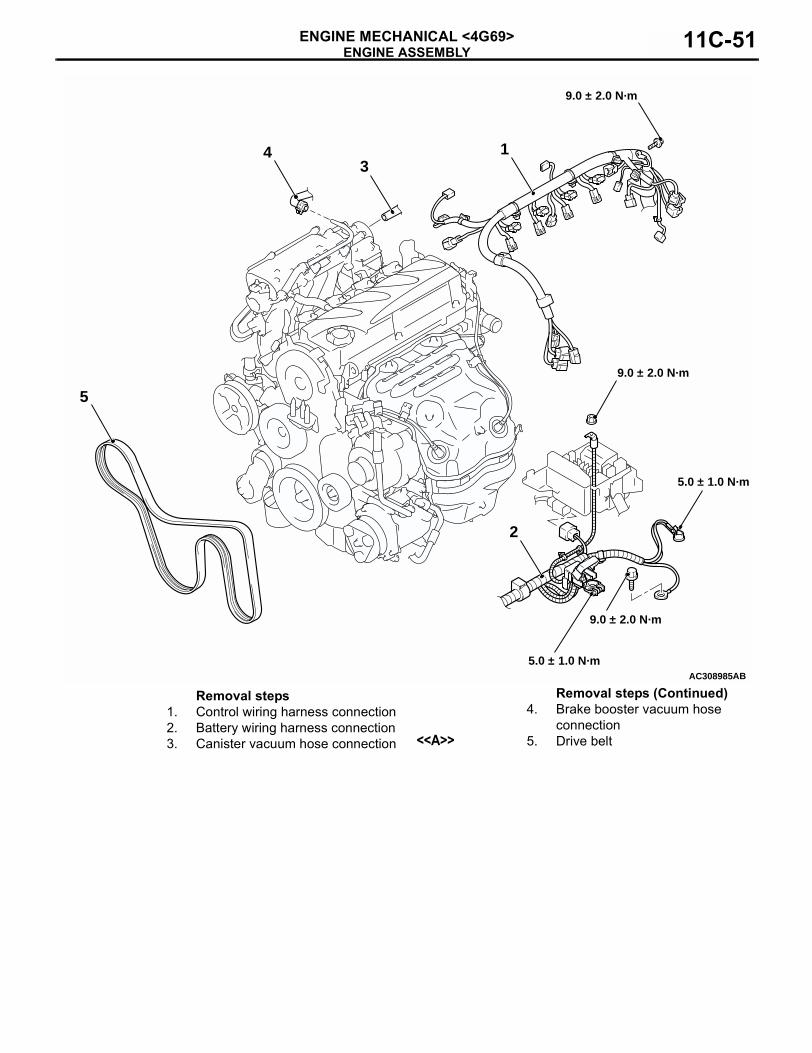
AC308985
5.0 ± 1.0 N·m
5.0 ± 1.0 N·m
9.0 ± 2.0 N·m
9.0 ± 2.0 N·m
9.0 ± 2.0 N·m
1
5
43
2
AB
Removal steps1. Control wiring harness connection 2. Battery wiring harness connection 3. Canister vacuum hose connection
4. Brake booster vacuum hose connection
<<A>> 5. Drive belt
Removal steps (Continued)
ENGINE ASSEMBLYENGINE MECHANICAL <4G69>11C-52
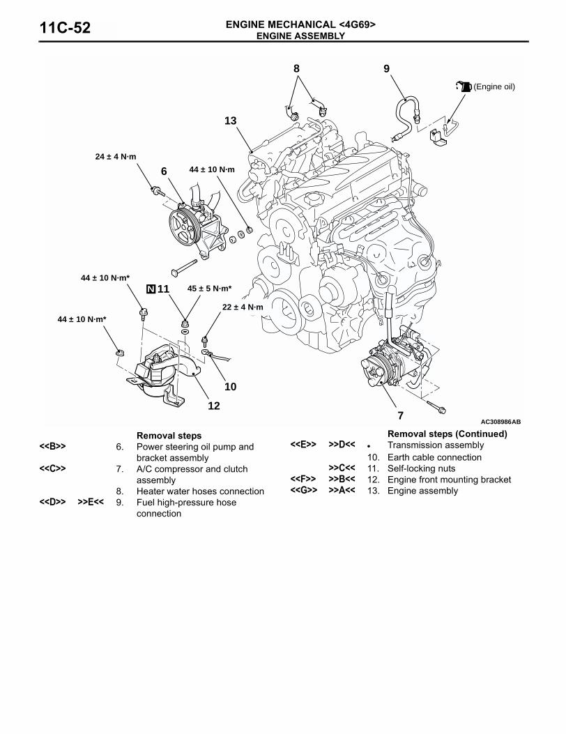
AC308986AB
(Engine oil)
13
98
7
624 ± 4 N·m
44 ± 10 N·m
12
10
11 45 ± 5 N·m*44 ± 10 N·m*
44 ± 10 N·m*22 ± 4 N·m
N
Removal steps<<B>> 6. Power steering oil pump and
bracket assembly<<C>> 7. A/C compressor and clutch
assembly8. Heater water hoses connection
<<D>> >>E<< 9. Fuel high-pressure hose connection
<<E>> >>D<< • Transmission assembly10. Earth cable connection
>>C<< 11. Self-locking nuts<<F>> >>B<< 12. Engine front mounting bracket<<G>> >>A<< 13. Engine assembly
Removal steps (Continued)
ENGINE ASSEMBLYENGINE MECHANICAL <4G69> 11C-53
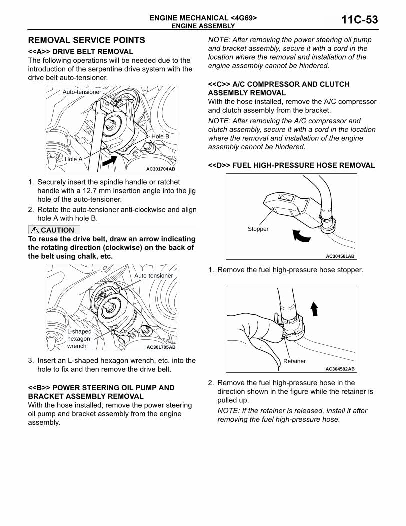
REMOVAL SERVICE POINTS<<A>> DRIVE BELT REMOVALThe following operations will be needed due to the introduction of the serpentine drive system with the drive belt auto-tensioner.
1. Securely insert the spindle handle or ratchet handle with a 12.7 mm insertion angle into the jig hole of the auto-tensioner.
2. Rotate the auto-tensioner anti-clockwise and align hole A with hole B.CAUTION
To reuse the drive belt, draw an arrow indicating the rotating direction (clockwise) on the back of the belt using chalk, etc.
3. Insert an L-shaped hexagon wrench, etc. into the hole to fix and then remove the drive belt.
<<B>> POWER STEERING OIL PUMP AND BRACKET ASSEMBLY REMOVALWith the hose installed, remove the power steering oil pump and bracket assembly from the engine assembly.
NOTE: After removing the power steering oil pump and bracket assembly, secure it with a cord in the location where the removal and installation of the engine assembly cannot be hindered.
<<C>> A/C COMPRESSOR AND CLUTCH ASSEMBLY REMOVALWith the hose installed, remove the A/C compressor and clutch assembly from the bracket.NOTE: After removing the A/C compressor and clutch assembly, secure it with a cord in the location where the removal and installation of the engine assembly cannot be hindered.
<<D>> FUEL HIGH-PRESSURE HOSE REMOVAL
1. Remove the fuel high-pressure hose stopper.
2. Remove the fuel high-pressure hose in the direction shown in the figure while the retainer is pulled up. NOTE: If the retainer is released, install it after removing the fuel high-pressure hose.
AC301703
AC301704AB
Hole A
Auto-tensioner
Hole B
AC301705AB
L-shapedhexagonwrench
Auto-tensioner
AC304581AB
Stopper
AC304582AB
Retainer
ENGINE ASSEMBLYENGINE MECHANICAL <4G69>11C-54
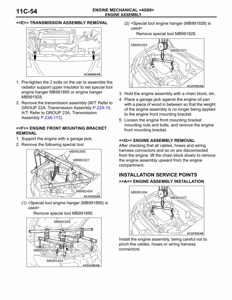
<<E>> TRANSMISSION ASSEMBLY REMOVAL
1. Pre-tighten the 2 bolts on the car to assemble the radiator support upper insulator to set special tool engine hanger MB991895 or engine hanger MB991928.
2. Remove the transmission assembly (M/T: Refer to GROUP 22A, Transmission Assembly P.22A-15, A/T: Refer to GROUP 23A, Transmission Assembly P.23A-172).
<<F>> ENGINE FRONT MOUNTING BRACKET REMOVAL1. Support the engine with a garage jack.2. Remove the following special tool.
(1) <Special tool engine hanger (MB991895) is used>
Remove special tool MB991895.
(2) <Special tool engine hanger (MB991928) is used>
Remove special tool MB991928.
3. Hold the engine assembly with a chain block, etc.4. Place a garage jack against the engine oil pan
with a piece of wood in between so that the weight of the engine assembly is no longer being applied to the engine front mounting bracket.
5. Loosen the engine front mounting bracket mounting nuts and bolts, and remove the engine front mounting bracket.
<<G>> ENGINE ASSEMBLY REMOVALAfter checking that all cables, hoses and wiring harness connectors and so on are disconnected from the engine, lift the chain block slowly to remove the engine assembly upward from the engine compartment.
INSTALLATION SERVICE POINTS>>A<< ENGINE ASSEMBLY INSTALLATION
Install the engine assembly, being careful not to pinch the cables, hoses or wiring harness connectors.
AC300950AB
AC107631AB
MB991527
MB991454
MB991895
AC211405AB
MB991527
MB991454
MB991928
AC107632 AB
MB991527
MB991454
AC107632 AB
MB991527
MB991454
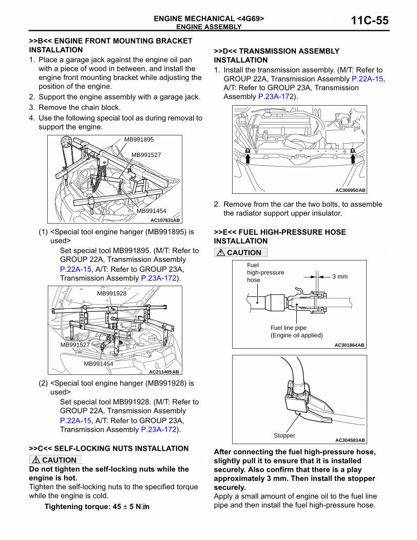
ENGINE ASSEMBLYENGINE MECHANICAL <4G69> 11C-55
>>B<< ENGINE FRONT MOUNTING BRACKET INSTALLATION1. Place a garage jack against the engine oil pan
with a piece of wood in between, and install the engine front mounting bracket while adjusting the position of the engine.
2. Support the engine assembly with a garage jack.3. Remove the chain block.4. Use the following special tool as during removal to
support the engine.
(1) <Special tool engine hanger (MB991895) is used>
Set special tool MB991895. (M/T: Refer to GROUP 22A, Transmission Assembly P.22A-15, A/T: Refer to GROUP 23A, Transmission Assembly P.23A-172).
(2) <Special tool engine hanger (MB991928) is used>
Set special tool MB991928. (M/T: Refer to GROUP 22A, Transmission Assembly P.22A-15, A/T: Refer to GROUP 23A, Transmission Assembly P.23A-172).
>>C<< SELF-LOCKING NUTS INSTALLATIONCAUTION
Do not tighten the self-locking nuts while the engine is hot.Tighten the self-locking nuts to the specified torque while the engine is cold.
Tightening torque: 45 ± 5 N⋅m
>>D<< TRANSMISSION ASSEMBLY INSTALLATION1. Install the transmission assembly. (M/T: Refer to
GROUP 22A, Transmission Assembly P.22A-15, A/T: Refer to GROUP 23A, Transmission Assembly P.23A-172).
2. Remove from the car the two bolts, to assemble the radiator support upper insulator.
>>E<< FUEL HIGH-PRESSURE HOSE INSTALLATION
CAUTION
After connecting the fuel high-pressure hose, slightly pull it to ensure that it is installed securely. Also confirm that there is a play approximately 3 mm. Then install the stopper securely.Apply a small amount of engine oil to the fuel line pipe and then install the fuel high-pressure hose.
AC107631AB
MB991527
MB991454
MB991895
AC211405AB
MB991527
MB991454
MB991928
AC300950AB
AC301864AB
3 mm
Fuel high-pressure hose
Fuel line pipe(Engine oil applied)
AC304583ABStopper

NOTES