Embed Size (px)
Citation preview
Ground-Mounted Verticals
Dispelling the Myths and Misconceptions
Ground-Mounted Verticals
Let’s start with a quiz on vertical antennas and radials.
Answers will be there to discover, as we proceed through the presentation.
Ground-Mounted Verticals
To be most effective, a ground-mounted vertical monopole antenna installation must have a quarter wavelength radiator and 120 radials at least a half wavelength long, over a coastal salt water marsh.
True?
False?
Ground-Mounted Verticals
Vertical radiators must be a quarter wave, 5/8 wave, half wave or full wave in length.
True?
False?

Ground-Mounted Verticals
Vertical radiators must be at least 2” in diameter.
True
False?
Ground-Mounted Verticals
Buried radial wires must be a quarter wave in length on each band
True?
False
Ground-Mounted Verticals
Radial wires must be as thick as possible.
True ?
False?
Ground-Mounted Verticals
Radials must consist of bare wire to improve contact with the soil.
True?
False?
Ground-Mounted Verticals
Radial wires must be buried at least six inches deep.
True?
False?
Ground-Mounted Verticals
Double the number of radials and you will double the antenna “gain”
True?
False?
Ground-Mounted Verticals
Horizontal wire dipoles and antenna arrays have low elevation (or take-off) angles (near the horizon), whereas vertical antennas launch most of their signal vertically.
True?
False?
Ground-Mounted VerticalsThe Radio Canada International installation works superbly well over the Tantramar Marsh at Sackville, NB. (But, in addition to the 1070 kHz CBA vertical monopole, it uses wire arrays on short-wave.)
Is such an extreme setup necessary for radio amateurs?
If not, how much does a modest Vertical setup suffer by comparison?
For answers let’s look at the comprehensive tables and curves from the excellent June 1985 QST article by Brian Edward N2MF, starting with ground characteristics and proceeding through radial configurations.
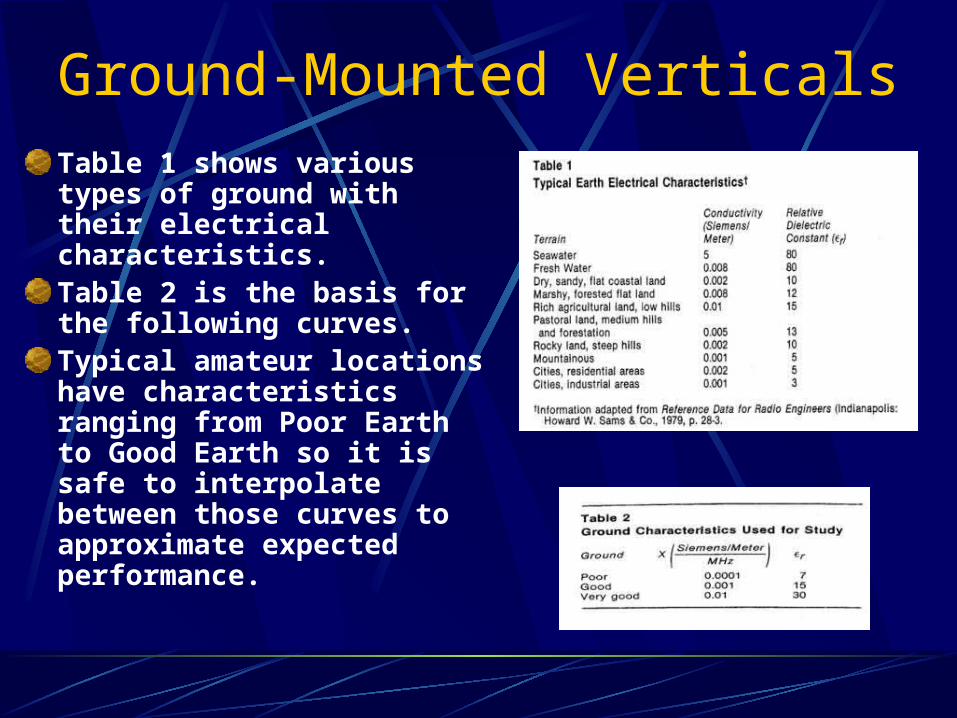
Ground-Mounted VerticalsTable 1 shows various types of ground with their electrical characteristics. Table 2 is the basis for the following curves. Typical amateur locations have characteristics ranging from Poor Earth to Good Earth so it is safe to interpolate between those curves to approximate expected performance.
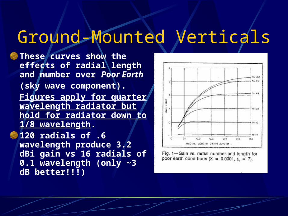
Ground-Mounted VerticalsThese curves show the effects of radial length and number over Poor Earth (sky wave component).Figures apply for quarter wavelength radiator but hold for radiator down to 1/8 wavelength.120 radials of .6 wavelength produce 3.2 dBi gain vs 16 radials of 0.1 wavelength (only ~3 dB better!!!)
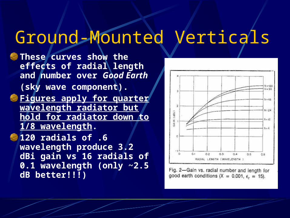
Ground-Mounted VerticalsThese curves show the effects of radial length and number over Good Earth
(sky wave component).Figures apply for quarter wavelength radiator but hold for radiator down to 1/8 wavelength.120 radials of .6 wavelength produce 3.2 dBi gain vs 16 radials of 0.1 wavelength (only ~2.5 dB better!!!)
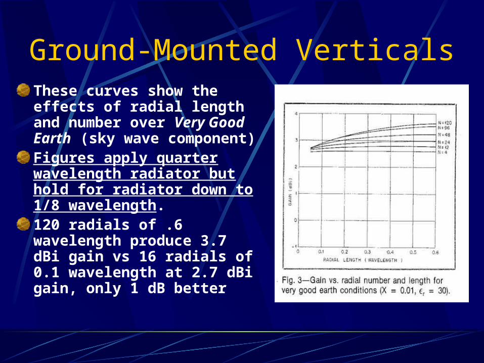
Ground-Mounted VerticalsThese curves show the effects of radial length and number over Very Good Earth (sky wave component) Figures apply quarter wavelength radiator but hold for radiator down to 1/8 wavelength.120 radials of .6 wavelength produce 3.7 dBi gain vs 16 radials of 0.1 wavelength at 2.7 dBi gain, only 1 dB better
Ground-Mounted Verticals
Q - What type of ground do I have in my back yard?A - You can measure soil conductivity using a simple meter and probe(s) (See Reference 3 on last slide). BUT what you really need to know is the average ground conductivity over several wavelengths from your antenna (which is impractical for an amateur to measure, especially for the lower frequency HF bands).Actual soil conductivity may vary with moisture content throughout the year, and you can’t do much about that.For most locations, using Table 1 and Table 2, and interpolating the curves between Poor Earth and Good Earth is appropriate for planning an amateur radio vertical antenna installation.
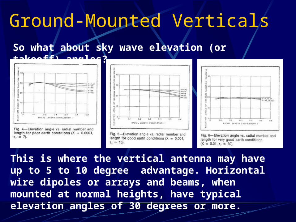
Ground-Mounted VerticalsSo what about sky wave elevation (or takeoff) angles?
This is where the vertical antenna may have up to 5 to 10 degree advantage. Horizontal wire dipoles or arrays and beams, when mounted at normal heights, have typical elevation angles of 30 degrees or more.
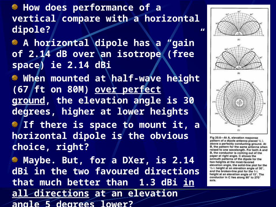
How does performance of a vertical compare with a horizontal dipole?
A horizontal dipole has a “gain” of 2.14 dB over an isotrope (free space) ie 2.14 dBi
When mounted at half-wave height (67 ft on 80M) over perfect ground, the elevation angle is 30 degrees, higher at lower heights
If there is space to mount it, a horizontal dipole is the obvious choice, right?
Maybe. But, for a DXer, is 2.14 dBi in the two favoured directions that much better than 1.3 dBi in all directions at an elevation angle 5 degrees lower?
High gain Yagis have narrow beam widths so can miss signals from another direction. Ideally use both – the vertical for “spotting”
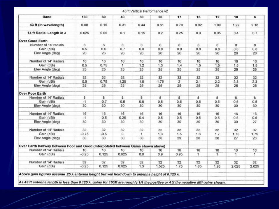
Ground-Mounted VerticalsBuried radials are not resonant and need not be a full, half or quarter wave long. Rather they collectively form a capacitance to “real ground”. Use of insulated #12 or #14 wire minimizes wire corrosionRadials can be slightly buried or on the surface, but if elevated more than a few feet, become resonant counterpoises, and then must be cut for each band.There are many commercial verticals on the market. Five of these are the new easy to install 43 ft verticalsFour are shiny aluminum tubing ( that attract neighbour attention and perhaps radiation concerns).Only one, the S9v43 from LDG, is forest green fibreglass. It is also the cheapest and lightest of all.How do 43 ft verticals relate to the previous curves?
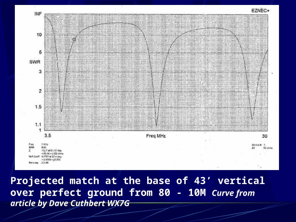
Projected match at the base of 43’ vertical over perfect ground from 80 - 10M Curve from article by Dave Cuthbert WX7G
Ground-Mounted VerticalsConclusions
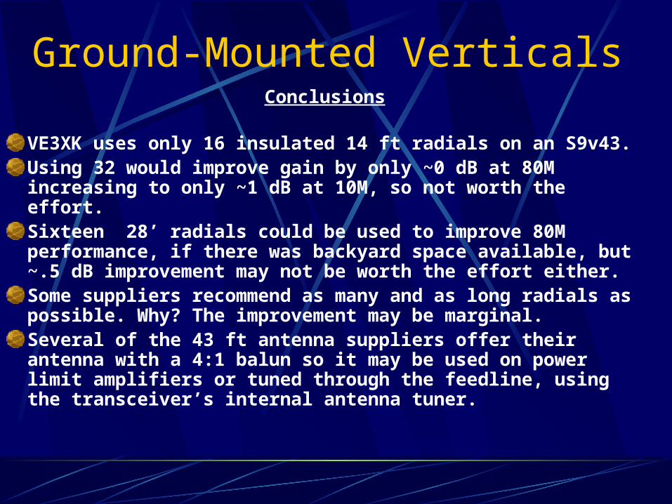
VE3XK uses only 16 insulated 14 ft radials on an S9v43. Using 32 would improve gain by only ~0 dB at 80M increasing to only ~1 dB at 10M, so not worth the effort. Sixteen 28’ radials could be used to improve 80M performance, if there was backyard space available, but ~.5 dB improvement may not be worth the effort either.Some suppliers recommend as many and as long radials as possible. Why? The improvement may be marginal. Several of the 43 ft antenna suppliers offer their antenna with a 4:1 balun so it may be used on power limit amplifiers or tuned through the feedline, using the transceiver’s internal antenna tuner.
Ground-Mounted VerticalsConclusions (cont’d)
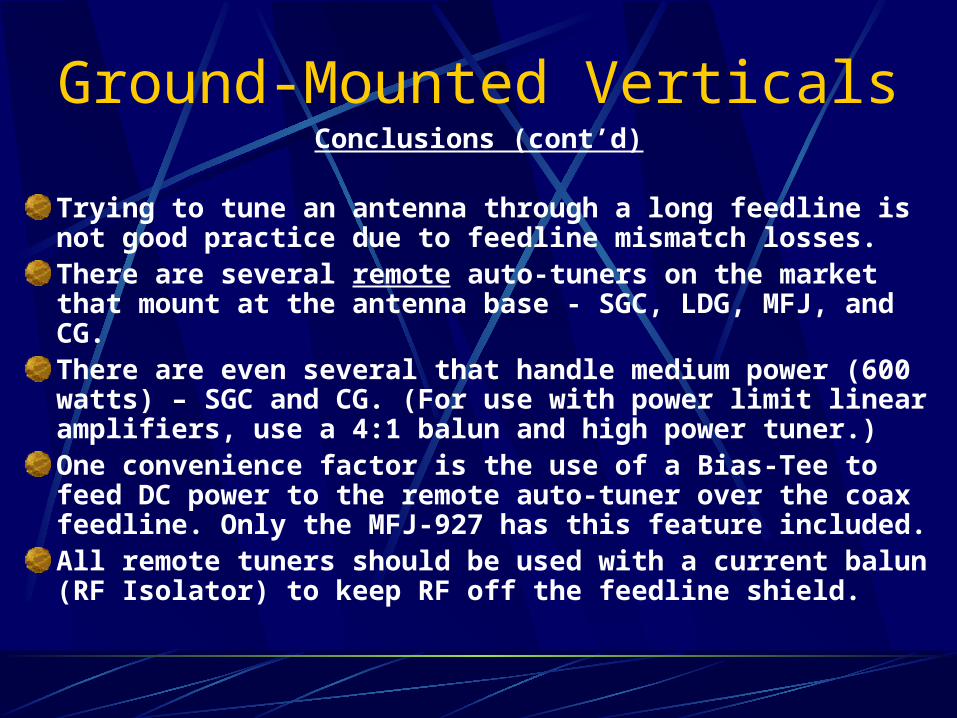
Trying to tune an antenna through a long feedline is not good practice due to feedline mismatch losses.There are several remote auto-tuners on the market that mount at the antenna base - SGC, LDG, MFJ, and CG.There are even several that handle medium power (600 watts) – SGC and CG. (For use with power limit linear amplifiers, use a 4:1 balun and high power tuner.) One convenience factor is the use of a Bias-Tee to feed DC power to the remote auto-tuner over the coax feedline. Only the MFJ-927 has this feature included.All remote tuners should be used with a current balun (RF Isolator) to keep RF off the feedline shield.
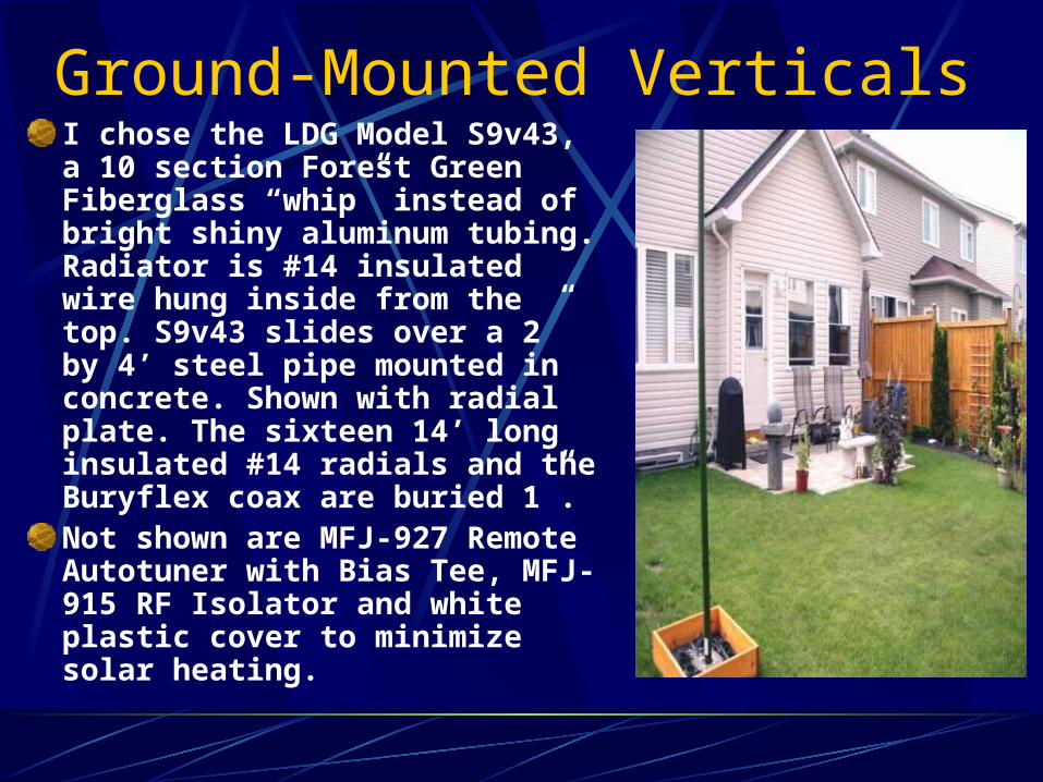
Ground-Mounted VerticalsI chose the LDG Model S9v43, a 10 section Forest Green Fiberglass “whip” instead of bright shiny aluminum tubing. Radiator is #14 insulated wire hung inside from the top. S9v43 slides over a 2” by 4’ steel pipe mounted in concrete. Shown with radial plate. The sixteen 14’ long insulated #14 radials and the Buryflex coax are buried 1”.Not shown are MFJ-927 Remote Autotuner with Bias Tee, MFJ-915 RF Isolator and white plastic cover to minimize solar heating.
Ground-Mounted Verticals
The setup is a dream to use - covers all bands 80M to 10M
Bandswitching is fast. Just transmit a carrier and the MFJ-927 tunes automatically in under 5 seconds.
The unguyed S9v43 stood up to the big Bluesfest gusts and the remnants of Hurricane Irene. So far, so good.
It will soon get a coat of car wax to better shed winter ice.
This neighbor-friendly setup is fun to use on all HF bands.
Ground-Mounted Verticals
On-air SSB results over the first three weeks
58 from Dubai on 20M
59 from Thailand on 15M
58 from Australia on 40M
59 from Germany on 40M
59 from Rochester on 80M (not the best band).
So far, three new countries on SSB.
Ground-Mounted VerticalsReferences
Radial Systems for Ground-Mounted Vertical Antennas – Brian Edwards, N2MF - QST June 1985. Thanks to Maty Weinberg, Production Coordinator of ARRL for permission to use tables and curves from this article for this presentation.
The 43’ Vertical – a Theoretical Analysis - Dave Cuthbert WX7G http://www.eham.net/articles/21272 This article contains VSWR curves and projected elevation plots for various bands and coaxial feedline types.
Measurement of Soil Electrical Parameters at HF – Rudy Severns, N6LF www.antennasbyn6lf.com. This article provides instructions on building a meter and probe(s) as well as limitations on interpretation of results.

Questions?
Thank you de VE3XK