Embed Size (px)
Citation preview
ISSN: 2277-3754
ISO 9001:2008 Certified International Journal of Engineering and Innovative Technology (IJEIT)
Volume 5, Issue 3, September 2015
DOI:10.17605/OSF.IO/N4PK7 Page 151
Abstract— Computational fluid dynamics is a relatively young
field in engineering. This method revolves around the generation
of an accurate model and analyzing the accuracy of results. For
acquiring accurate results through CFD, developing an accurate
model is of utmost necessity. The grid dependency study of CFD
shows the relation between the accuracy of grid in representing
the body analyzed and results obtained.
Index Terms— Convergence, Grid Dependency, Mach
number NACA Air-foil, Residual history.
I. INTRODUCTION
Computational Fluid Dynamics (CFD) is a science
combining the aspects of fluid mechanics, numerical
methods and programming to solve the Partial Differential
Equations governing the fluid flow. The Applications of CFD
are wide spread across many fields of science where the flow
of the fluid appears. [3]
One of the most sensitive areas of engineering where
accuracy of CFD results is of high importance is aerospace
engineering. Hence improvement of accuracy in the results
obtained through CFD analysis has become an essential
aspect. Realizing that the accuracy primarily depends upon
quality of grid network around a body, numerous grid
dependency studies have been done. One of the prominent
study is “Grid Dependency Study for the NASA Rotor 37
compressor blade”[5], which provided a systematic grid
dependency study that quantified the amount of uncertainty
that comes from grid density.
Here the analysis on NACA 0012 airfoil shall be detailed
and discussed. The NACA 0012 airfoil is widely used in
aerospace industry. The simple and symmetric geometry of
NACA 0012 airfoil provides an excellent validation case.
To solve the fluid flow equations, a grid network around
the NACA 0012 airfoil is required to simulate the flow
around body. The fluid flow properties are obtained by
iteratively solving the fluid flow equations. Test for a good
quality grid which shall lead to an accurate solution
minimizing the projection error of the solution domain will
be shown.
II. PROCEDURE
CFD Analysis for an air-foil
Air-foils are classified by NACA based on the camber
length, maximum thickness and the roundedness etc. into
NACA 0012, NACA 0012-64 etc. There are different series
of air-foils namely four digit series, five digit series and six
digit series.
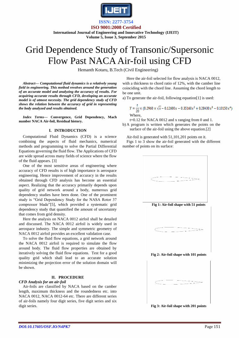
Here the air-foil selected for flow analysis is NACA 0012,
with a thickness to chord ratio of 12%, with the camber line
coinciding with the chord line. Assuming the chord length to
be one unit.
a) To generate the air-foil, following equation[1] is used:
Where,
t=0.12 for NACA 0012 and x ranging from 0 and 1.
b) A program is written which generates the points on the
surface of the air-foil using the above equation.[2]
Air-foil is generated with 51,101,201 points on it.
Figs 1 to 3 show the air-foil generated with the different
number of points on its surface:
Fig 1: Air-foil shape with 51 points
Fig 2: Air-foil shape with 101 points
Fig 3: Air-foil shape with 201 points
Grid Dependence Study of Transonic/Supersonic
Flow Past NACA Air-foil using CFD Hemanth Kotaru, B.Tech (Civil Engineering)
ISSN: 2277-3754
ISO 9001:2008 Certified International Journal of Engineering and Innovative Technology (IJEIT)
Volume 5, Issue 3, September 2015
DOI:10.17605/OSF.IO/N4PK7 Page 152
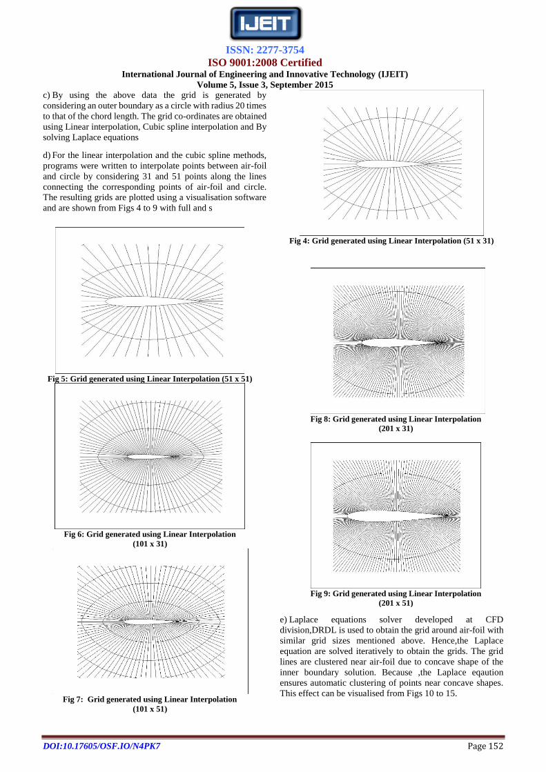
c) By using the above data the grid is generated by
considering an outer boundary as a circle with radius 20 times
to that of the chord length. The grid co-ordinates are obtained
using Linear interpolation, Cubic spline interpolation and By
solving Laplace equations
d) For the linear interpolation and the cubic spline methods,
programs were written to interpolate points between air-foil
and circle by considering 31 and 51 points along the lines
connecting the corresponding points of air-foil and circle.
The resulting grids are plotted using a visualisation software
and are shown from Figs 4 to 9 with full and s
Fig 4: Grid generated using Linear Interpolation (51 x 31)
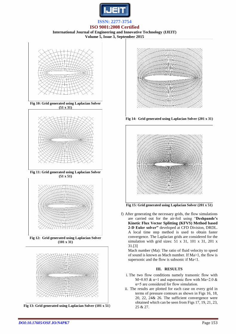
e) Laplace equations solver developed at CFD
division,DRDL is used to obtain the grid around air-foil with
similar grid sizes mentioned above. Hence,the Laplace
equation are solved iteratively to obtain the grids. The grid
lines are clustered near air-foil due to concave shape of the
inner boundary solution. Because ,the Laplace eqaution
ensures automatic clustering of points near concave shapes.
This effect can be visualised from Figs 10 to 15.
Fig 5: Grid generated using Linear Interpolation (51 x 51)
Fig 6: Grid generated using Linear Interpolation
(101 x 31)
Fig 7: Grid generated using Linear Interpolation
(101 x 51)
Fig 8: Grid generated using Linear Interpolation
(201 x 31)
Fig 9: Grid generated using Linear Interpolation
(201 x 51)
ISSN: 2277-3754
ISO 9001:2008 Certified International Journal of Engineering and Innovative Technology (IJEIT)
Volume 5, Issue 3, September 2015
DOI:10.17605/OSF.IO/N4PK7 Page 153
Fig 13: Grid generated using Laplacian Solver (101 x 51)
Fig 14: Grid generated using Laplacian Solver (201 x 31)
Fig 15: Grid generated using Laplacian Solver (201 x 51)
f) After generating the necessary grids, the flow simulations
are carried out for the air-foil using “Deshpande’s
Kinetic Flux Vector Splitting (KFVS) Method based
2-D Euler solver” developed at CFD Division, DRDL.
A local time step method is used to obtain faster
convergence. The Laplacian grids are considered for the
simulation with grid sizes: 51 x 31, 101 x 31, 201 x
31.[3]
Mach number (Ma): The ratio of fluid velocity to speed
of sound is known as Mach number. If Ma>1, the flow is
supersonic and the flow is subsonic if Ma<1.
III. RESULTS
i. The two flow conditions namely transonic flow with
M=0.85 & α=1 and supersonic flow with Ma=2.0 &
α=5 are considered for flow simulation.
ii. The results are plotted for each case on every grid in
terms of pressure contours as shown in Figs 16, 18,
20, 22, 24& 26. The sufficient convergence were
obtained which can be seen from Figs 17, 19, 21, 23,
25 & 27.
Fig 10: Grid generated using Laplacian Solver
(51 x 31)
Fig 11: Grid generated using Laplacian Solver
(51 x 51)
Fig 12: Grid generated using Laplacian Solver
(101 x 31)
ISSN: 2277-3754
ISO 9001:2008 Certified International Journal of Engineering and Innovative Technology (IJEIT)
Volume 5, Issue 3, September 2015
DOI:10.17605/OSF.IO/N4PK7 Page 154
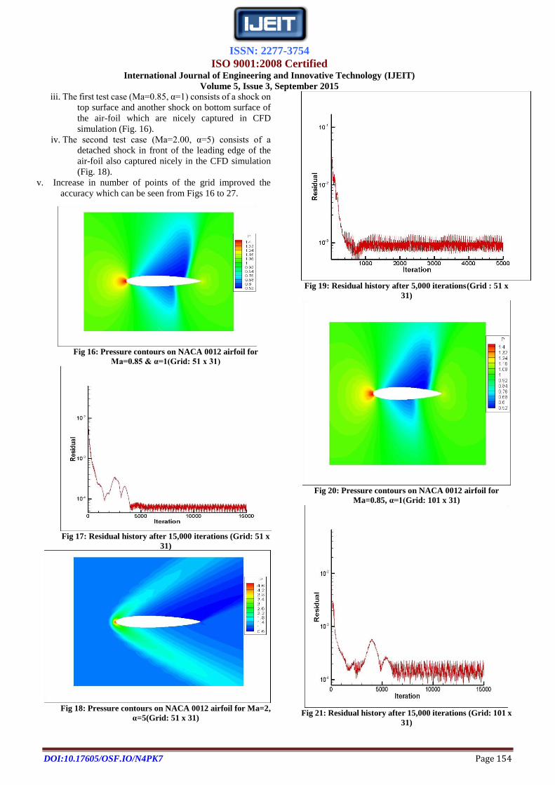
iii. The first test case (Ma=0.85, α=1) consists of a shock on
top surface and another shock on bottom surface of
the air-foil which are nicely captured in CFD
simulation (Fig. 16).
iv. The second test case (Ma=2.00, α=5) consists of a
detached shock in front of the leading edge of the
air-foil also captured nicely in the CFD simulation
(Fig. 18).
v. Increase in number of points of the grid improved the
accuracy which can be seen from Figs 16 to 27.
Fig 16: Pressure contours on NACA 0012 airfoil for
Ma=0.85 & α=1(Grid: 51 x 31)
Fig 17: Residual history after 15,000 iterations (Grid: 51 x
31)
Fig 18: Pressure contours on NACA 0012 airfoil for Ma=2,
α=5(Grid: 51 x 31)
Fig 19: Residual history after 5,000 iterations (Grid : 51 x
31)
Fig 20: Pressure contours on NACA 0012 airfoil for
Ma=0.85, α=1(Grid: 101 x 31)
Fig 21: Residual history after 15,000 iterations (Grid: 101 x
31)
ISSN: 2277-3754
ISO 9001:2008 Certified International Journal of Engineering and Innovative Technology (IJEIT)
Volume 5, Issue 3, September 2015
DOI:10.17605/OSF.IO/N4PK7 Page 155
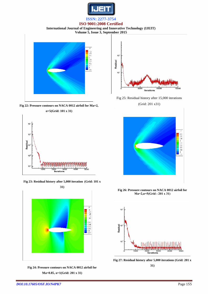
Fig 22: Pressure contours on NACA 0012 airfoil for Ma=2,
α=5(Grid: 101 x 31)
Fig 23: Residual history after 5,000 iteration (Grid: 101 x
31)
Fig 24: Pressure contours on NACA 0012 airfoil for
Ma=0.85, α=1(Grid: 201 x 31)
Fig 25: Residual history after 15,000 iterations
(Grid: 201 x31)
Fig 26: Pressure contours on NACA 0012 airfoil for
Ma=2,α=5(Grid : 201 x 31)
Fig 27: Residual history after 5,000 iterations (Grid: 201 x
31)
ISSN: 2277-3754
ISO 9001:2008 Certified International Journal of Engineering and Innovative Technology (IJEIT)
Volume 5, Issue 3, September 2015
DOI:10.17605/OSF.IO/N4PK7 Page 156
vi. The lift and drag coefficients are presented in Table-1
for these two cases on different grids and the effect
of grid size can be clearly seen.
IV. CONCLUSION
The effect of grids on the flow and aerodynamic
coefficients are studied using α 2-D Euler Solver. The
necessity of more points and clustering of points near body is
emphasized to increase the accuracy of the flow. It is also
seen that the solution for supersonic flow condition
converges faster when compared to transonic case. The
accuracy of the flow can be further improved if more points
are clustered near the airfoil.
V. FUTURE ENHANCEMENT
With keen insights obtained from the grid dependency
study of NACA 0012, development of optimum sized grid
can be applied to several other aerodynamic structures.
REFERENCES [1] Charles L. Ladson, Cuyler W. Brooks, Jr., Acquilla S.Hill, and
Darrell W. Sproles, “Computer Program To Obtain Ordinates
for NACA Airfoils”, NASA Technical Memorandum 4741.
[2] Ira H. Abbott, A. E. von Doenhoff, “Theory of Wing Sections”.
[3] Dr Zhexuan Wang, “Computational Fluid Dynamics (CFD)
Analysis of NACA 0012 Airfoil”.
[4] Mohamed Sukri Mat Ali, Con J. Doolan and Vincent
Wheatley, “Grid convergence study for a two-dimensional
simulation of flow around a square cylinder at a low
Reynolds’s number”, Seventh International Conference on
CFD in the Minerals and Process Industries CSIRO,
Melbourne, Australia 9-11 December 2009].
[5] Andrea Arnone,Ennio Antonio Carnevale, Michele
Marconcini,“Grid Dependency Study for the NASA Rotor 37
Compressor Blade”, ASME Turbo Expo, At Orlando, FL,
USA, Volume: 1: Aircraft Engine; Marine; Turbo machinery;
Micro-turbines and Small Turbo machinery.
PERSONAL PROFILE
Hemanth Kotaru-
I am currently working at a premiere engineering software development
organization Hexagon AB as Software analyst. I graduated from Gokaraju
Rangaraju Institute of Engineering and Technology in Civil Engineering.My
interests are structural design in aerospace engineering, structural dynamics
and computational mechanics. My inquisitiveness and thirst for knowledge
has enabled me complete a total of 3 projects and an internship. I am
currently working independently on wing design project for an aircraft. I was
a member of IEEE and ICI for 2 years and served in several office bearer
positions.
Flow
Condition
Grids Lift co-eff.
CL
Drag co-eff.
CD
Mach 0.85
= 10 51 x 31
101 x 31
201 x 31
0.3105
0.2698
0.252
0.0922
0.0837
0.0755
Mach 0.85
= 50
51 x 31
101 x 31
201 x 31
1.0620
1.0260
1.0496
0.763
0.768
0.7351