Embed Size (px)
DESCRIPTION
Guidelines for green street design
Citation preview
A-1
KEY DESIGN AND CONSTRUCTION DETAILS
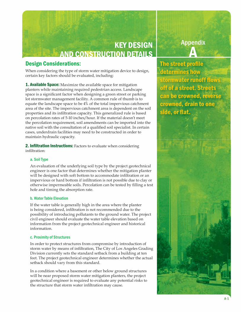
Design Considerations:When considering the type of storm water mitigation device to design, certain key factors should be evaluated, including:
1. Available Space: Maximize the available space for mitigation planters while maintaining required pedestrian access. Landscape space is a signifi cant factor when designing a green street or parking lot stormwater management facility. A common rule of thumb is to equate the landscape space to be 4% of the total impervious catchment area of the site. The impervious catchment area is dependent on the soil properties and its infi ltration capacity. This generalized rule is based on percolation rates of 5-10 inches/hour. If the material doesn’t meet the percolation requirement, soil amendments can be imported into the native soil with the consultation of a qualifi ed soil specialist. In certain cases, underdrain facilities may need to be constructed in order to maintain hydraulic capacity.
2. Infi ltration Instructions: Factors to evaluate when considering infi ltration:
a. Soil TypeAn evaluation of the underlying soil type by the project geotechnical engineer is one factor that determines whether the mitigation planter will be designed with soft bottom to accommodate infi ltration or an impervious or hard bottom if infi ltration is not possible due to clay or otherwise impermeable soils. Percolation can be tested by fi lling a test hole and timing the absorption rate.
b. Water Table ElevationIf the water table is generally high in the area where the planter is being considered, infi ltration is not recommended due to the possibility of introducing pollutants to the ground water. The project civil engineer should evaluate the water table elevation based on information from the project geotechnical engineer and historical information.
c. Proximity of StructuresIn order to protect structures from compromise by introduction of storm water by means of infi ltration, The City of Los Angeles Grading Division currently sets the standard setback from a building at ten feet. The project geotechnical engineer determines whether the actual setback should vary from this standard.
In a condition where a basement or other below ground structures will be near proposed storm water mitigation planters, the project geotechnical engineer is required to evaluate any potential risks to the structure that storm water infi ltration may cause.
Appendix
AThe street profi le determines how stormwater runoff fl ows off of a street. Streets can be crowned, reverse crowned, drain to one side, or fl at.
APPENDIX A: KEY DESIGN AND CONSTRUCTION DETAILS
A-2
d. Presence of contaminated ground water, soil or storage tanks
Infi ltration is not appropriate in these conditions.
3. Stormwater overfl ow: An overfl ow drain that conducts runoff from larger storm events increases the lifespan and pollutant removal capacity of the plants. The overfl ow drains through the curb face or is piped into the storm drain.
Decision Process Guidelines: Steps to be Taken by Design Team
Evaluate right-of-way width in terms of required 1. road and sidewalk width. How much room is possible for a mitigation feature?
Review substructure maps and utility plans for 2. project to evaluate potential underground confl icts for planters.
Prepare an evaluation of the underlying soil 3. condition and proximity to structures. Consider whether infi ltration is appropriate given the soil type and structure proximity.
Determine historical and actual water table 4. elevations; if planter is proposed in an area of high groundwater (10’ or less below the surface), infi ltration is not considered appropriate.
Select type of mitigation feature based on the above.5.
Prepare detailed plans, reports and calculations to 6. support design decisions.
Apply for a Revocable Permit for conditional 7. approval of the encroachment into the public right-of-way. Include features such as landscaping, irrigation, grates, and pavers. Obtain Waiver of Damages Agreement and provide liability insurance.
Prepare an Operations and Maintenance manual. 8. Include a schedule for periodic inspections and the removal of trash and debris. File a Covenant and Agreement for maintenance to run with the land.
Submit plans to Bureau of Engineering for fi nal 9. approval.
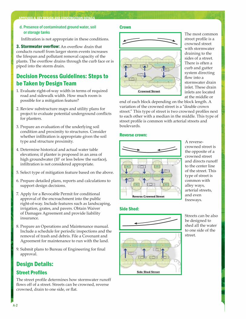
Design Details:Street Profi lesThe street profi le determines how stormwater runoff fl ows off of a street. Streets can be crowned, reverse crowned, drain to one side, or fl at.
Crown The most common street profi le is a crowned street with stormwater draining to the sides of a street. There is often a curb and gutter system directing fl ow into a stormwater drain inlet. These drain inlets are located at the middle or
end of each block depending on the block length. A variation of the crowned street is a “double crown street.” This type of street is two crowned profi les next to each other with a median in the middle. This type of street profi le is common with arterial streets and boulevards.
Reverse crown: A reverse-crowned street is the opposite of a crowned street and directs runoff to the center line of the street. This type of street is common with alley ways, arterial streets, and even freeways.
Side Shed:Streets can be also be designed to shed all the water to one side of the street.
APPENDIX A: KEY DESIGN AND CONSTRUCTION DETAILS
A-3
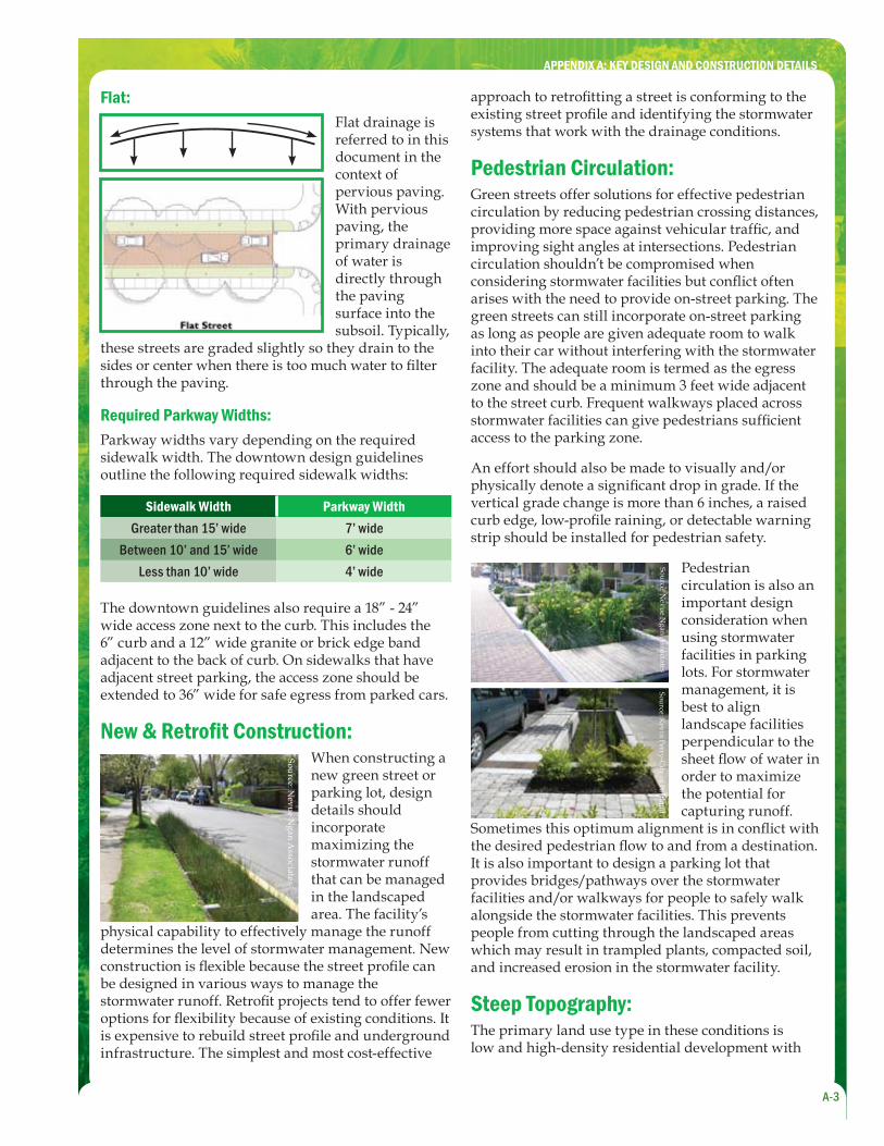
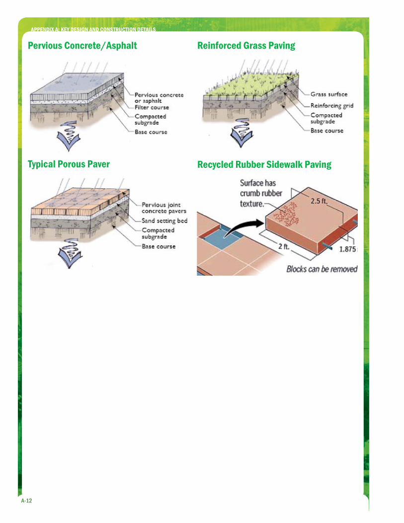
Flat: Flat drainage is referred to in this document in the context of pervious paving. With pervious paving, the primary drainage of water is directly through the paving surface into the subsoil. Typically,
these streets are graded slightly so they drain to the sides or center when there is too much water to fi lter through the paving.
Required Parkway Widths:Parkway widths vary depending on the required sidewalk width. The downtown design guidelines outline the following required sidewalk widths:
Sidewalk Width Parkway WidthGreater than 15’ wide 7’ wide
Between 10’ and 15’ wide 6’ wideLess than 10’ wide 4’ wide
The downtown guidelines also require a 18” - 24” wide access zone next to the curb. This includes the 6” curb and a 12” wide granite or brick edge band adjacent to the back of curb. On sidewalks that have adjacent street parking, the access zone should be extended to 36” wide for safe egress from parked cars.
New & Retrofi t Construction:
Source: Nevue N
gan Associates
When constructing a new green street or parking lot, design details should incorporate maximizing the stormwater runoff that can be managed in the landscaped area. The facility’s
physical capability to effectively manage the runoff determines the level of stormwater management. New construction is fl exible because the street profi le can be designed in various ways to manage the stormwater runoff. Retrofi t projects tend to offer fewer options for fl exibility because of existing conditions. It is expensive to rebuild street profi le and underground infrastructure. The simplest and most cost-effective
approach to retrofi tting a street is conforming to the existing street profi le and identifying the stormwater systems that work with the drainage conditions.
Pedestrian Circulation:Green streets offer solutions for effective pedestrian circulation by reducing pedestrian crossing distances, providing more space against vehicular traffi c, and improving sight angles at intersections. Pedestrian circulation shouldn’t be compromised when considering stormwater facilities but confl ict often arises with the need to provide on-street parking. The green streets can still incorporate on-street parking as long as people are given adequate room to walk into their car without interfering with the stormwater facility. The adequate room is termed as the egress zone and should be a minimum 3 feet wide adjacent to the street curb. Frequent walkways placed across stormwater facilities can give pedestrians suffi cient access to the parking zone.
An effort should also be made to visually and/or physically denote a signifi cant drop in grade. If the vertical grade change is more than 6 inches, a raised curb edge, low-profi le raining, or detectable warning strip should be installed for pedestrian safety.
Source: Nevue N
gan Associates
Source: Kevin Perry-C
ity of Portland
Pedestrian circulation is also an important design consideration when using stormwater facilities in parking lots. For stormwater management, it is best to align landscape facilities perpendicular to the sheet fl ow of water in order to maximize the potential for capturing runoff.
Sometimes this optimum alignment is in confl ict with the desired pedestrian fl ow to and from a destination. It is also important to design a parking lot that provides bridges/pathways over the stormwater facilities and/or walkways for people to safely walk alongside the stormwater facilities. This prevents people from cutting through the landscaped areas which may result in trampled plants, compacted soil, and increased erosion in the stormwater facility.
Steep Topography:The primary land use type in these conditions is low and high-density residential development with
APPENDIX A: KEY DESIGN AND CONSTRUCTION DETAILS
A-4
relatively narrow right-of-ways. Although these narrower streets may not generate large volumes of stormwater runoff, the velocity of stormwater runoff from developed hillsides is a potential concern. Hence, a good approach is to design stormwater facilities that help slow runoff as much as possible. There are several methods that can be used. First, look for ways to improve the overall site design so that space can be provided for stormwater facilities. Second, build terraced stormwater planters and swales that help fl atten the interior slopes of landscape areas compared to the steepness of a street or parking lot. Closely-spaced check dams and weirs can then help slow down the fl ow of water, mimicking a more natural condition. Depending on the underlying soil conditions, some of this water might also infi ltrate into the native soils. A geotechnical engineer should be consulted during the design process to evaluate and analyze steep areas for susceptibility to landslides.
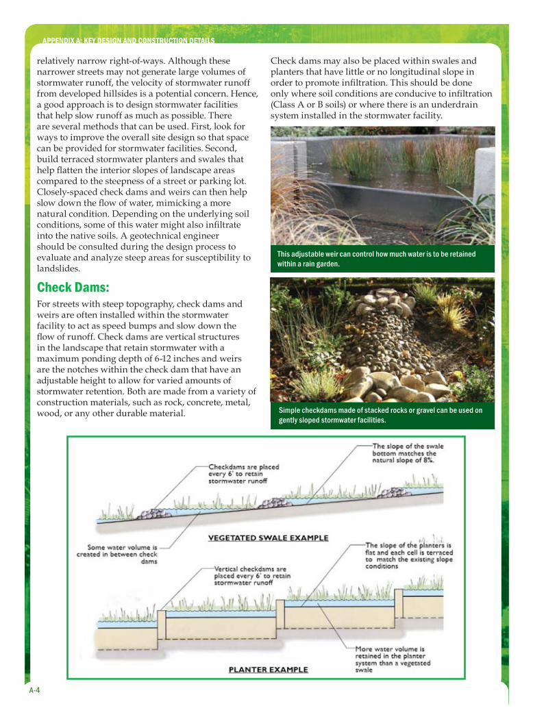
Check Dams:For streets with steep topography, check dams and weirs are often installed within the stormwater facility to act as speed bumps and slow down the fl ow of runoff. Check dams are vertical structures in the landscape that retain stormwater with a maximum ponding depth of 6-12 inches and weirs are the notches within the check dam that have an adjustable height to allow for varied amounts of stormwater retention. Both are made from a variety of construction materials, such as rock, concrete, metal, wood, or any other durable material.
Check dams may also be placed within swales and planters that have little or no longitudinal slope in order to promote infi ltration. This should be done only where soil conditions are conducive to infi ltration (Class A or B soils) or where there is an underdrain system installed in the stormwater facility.
Simple checkdams made of stacked rocks or gravel can be used on gently sloped stormwater facilities.
This adjustable weir can control how much water is to be retained within a rain garden.
APPENDIX A: KEY DESIGN AND CONSTRUCTION DETAILS
A-5
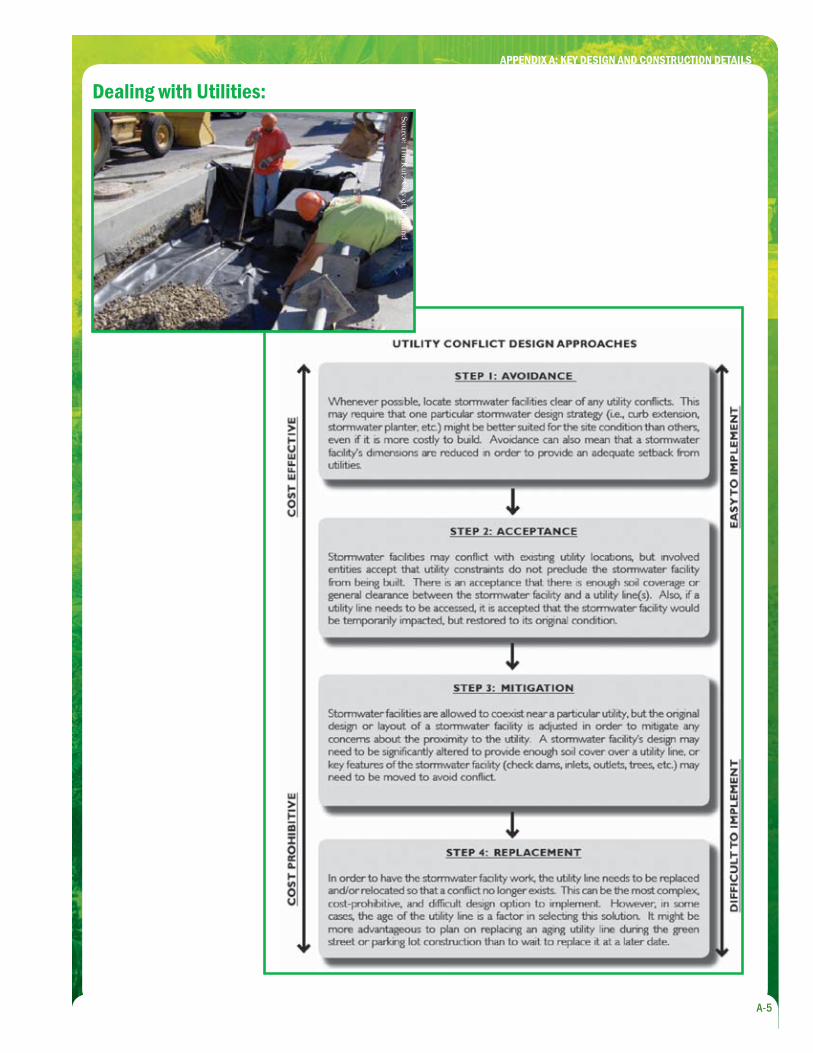
Dealing with Utilities:
Source: Tim K
utz City of Portland
APPENDIX A: KEY DESIGN AND CONSTRUCTION DETAILS
A-6
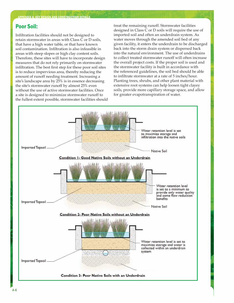
Poor Soil:Infi ltration facilities should not be designed to retain stormwater in areas with Class C or D soils, that have a high water table, or that have known soil contamination. Infi ltration is also infeasible in areas with steep slopes or high clay content soils. Therefore, these sites will have to incorporate design measures that do not rely primarily on stormwater infi ltration. The best fi rst step for these poor soil sites is to reduce impervious area, thereby reducing the amount of runoff needing treatment. Increasing a site’s landscape area by 25% is in essence decreasing the site’s stormwater runoff by almost 25% even without the use of active stormwater facilities. Once a site is designed to minimize stormwater runoff to the fullest extent possible, stormwater facilities should
treat the remaining runoff. Stormwater facilities designed in Class C or D soils will require the use of imported soil and often an underdrain system. As water moves through the amended soil bed of any given facility, it enters the underdrain to be discharged back into the storm drain system or dispersed back into the natural environment. The use of underdrains to collect treated stormwater runoff will often increase the overall project costs. If the proper soil is used and the stormwater facility is built in accordance with the referenced guidelines, the soil bed should be able to infi ltrate stormwater at a rate of 5 inches/hour. Planting trees, shrubs, and other plant material with extensive root systems can help loosen tight clayey soils, provide more capillary storage space, and allow for greater evapotranspiration of water.
APPENDIX A: KEY DESIGN AND CONSTRUCTION DETAILS
A-7
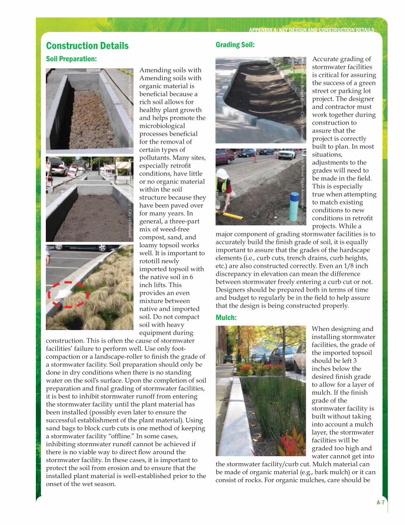
Construction DetailsSoil Preparation:
Source: Kevin R
obert Perry - City of Portland
Source: Kevin R
obert Perry - City of Portland
Source: Nevue N
gan Associates
Amending soils with Amending soils with organic material is benefi cial because a rich soil allows for healthy plant growth and helps promote the microbiological processes benefi cial for the removal of certain types of pollutants. Many sites, especially retrofi t conditions, have little or no organic material within the soil structure because they have been paved over for many years. In general, a three-part mix of weed-free compost, sand, and loamy topsoil works well. It is important to rototill newly imported topsoil with the native soil in 6 inch lifts. This provides an even mixture between native and imported soil. Do not compact soil with heavy equipment during
construction. This is often the cause of stormwater facilities’ failure to perform well. Use only foot-compaction or a landscape-roller to fi nish the grade of a stormwater facility. Soil preparation should only be done in dry conditions when there is no standing water on the soil’s surface. Upon the completion of soil preparation and fi nal grading of stormwater facilities, it is best to inhibit stormwater runoff from entering the stormwater facility until the plant material has been installed (possibly even later to ensure the successful establishment of the plant material). Using sand bags to block curb cuts is one method of keeping a stormwater facility “offl ine.” In some cases, inhibiting stormwater runoff cannot be achieved if there is no viable way to direct fl ow around the stormwater facility. In these cases, it is important to protect the soil from erosion and to ensure that the installed plant material is well-established prior to the onset of the wet season.
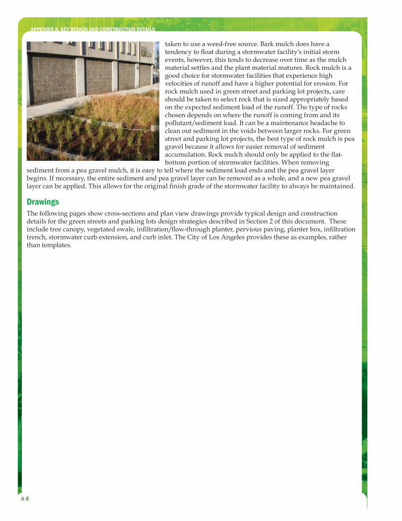
Grading Soil:
Source: Kevin R
obert Perry - City of Portland
Source: Nevue N
gan Associates
Accurate grading of stormwater facilities is critical for assuring the success of a green street or parking lot project. The designer and contractor must work together during construction to assure that the project is correctly built to plan. In most situations, adjustments to the grades will need to be made in the fi eld. This is especially true when attempting to match existing conditions to new conditions in retrofi t projects. While a
major component of grading stormwater facilities is to accurately build the fi nish grade of soil, it is equally important to assure that the grades of the hardscape elements (i.e., curb cuts, trench drains, curb heights, etc.) are also constructed correctly. Even an 1/8 inch discrepancy in elevation can mean the difference between stormwater freely entering a curb cut or not. Designers should be prepared both in terms of time and budget to regularly be in the fi eld to help assure that the design is being constructed properly.
Mulch:
Source: Nevue N
gan Associates
When designing and installing stormwater facilities, the grade of the imported topsoil should be left 3 inches below the desired fi nish grade to allow for a layer of mulch. If the fi nish grade of the stormwater facility is built without taking into account a mulch layer, the stormwater facilities will be graded too high and water cannot get into
the stormwater facility/curb cut. Mulch material can be made of organic material (e.g., bark mulch) or it can consist of rocks. For organic mulches, care should be
APPENDIX A: KEY DESIGN AND CONSTRUCTION DETAILS
A-8
Source: Nevue N
gan Associates
taken to use a weed-free source. Bark mulch does have a tendency to fl oat during a stormwater facility’s initial storm events, however, this tends to decrease over time as the mulch material settles and the plant material matures. Rock mulch is a good choice for stormwater facilities that experience high velocities of runoff and have a higher potential for erosion. For rock mulch used in green street and parking lot projects, care should be taken to select rock that is sized appropriately based on the expected sediment load of the runoff. The type of rocks chosen depends on where the runoff is coming from and its pollutant/sediment load. It can be a maintenance headache to clean out sediment in the voids between larger rocks. For green street and parking lot projects, the best type of rock mulch is pea gravel because it allows for easier removal of sediment accumulation. Rock mulch should only be applied to the fl at-bottom portion of stormwater facilities. When removing
sediment from a pea gravel mulch, it is easy to tell where the sediment load ends and the pea gravel layer begins. If necessary, the entire sediment and pea gravel layer can be removed as a whole, and a new pea gravel layer can be applied. This allows for the original fi nish grade of the stormwater facility to always be maintained.
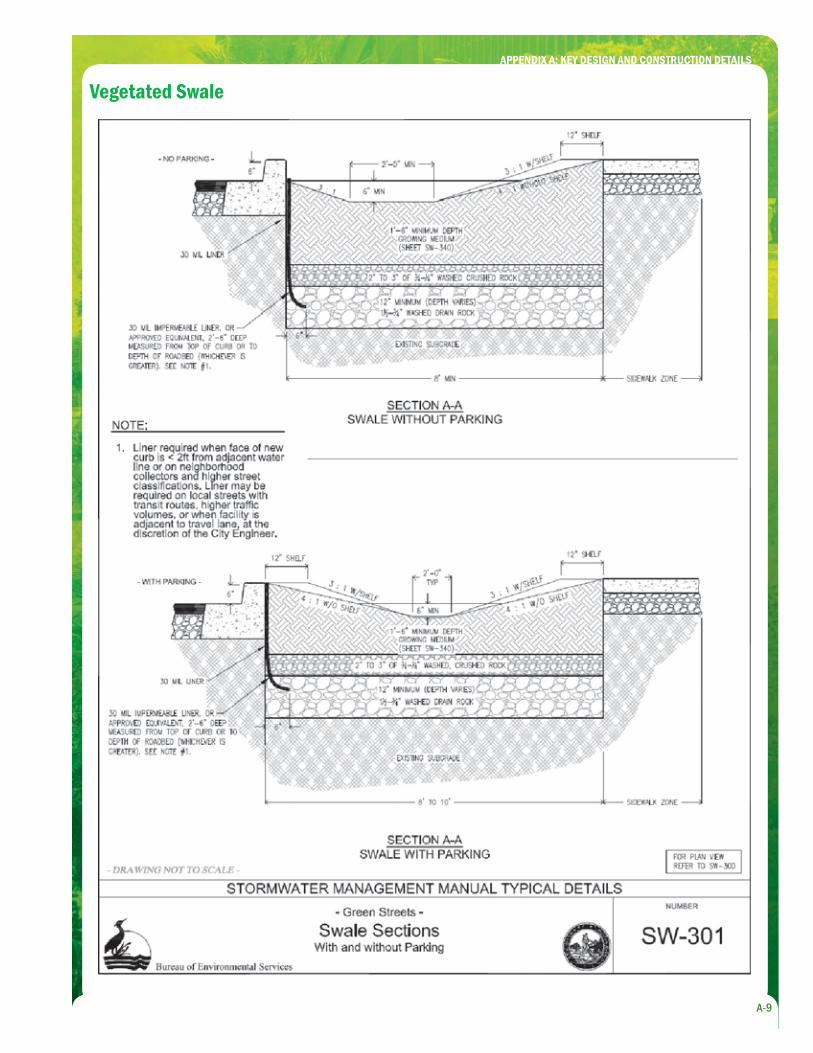
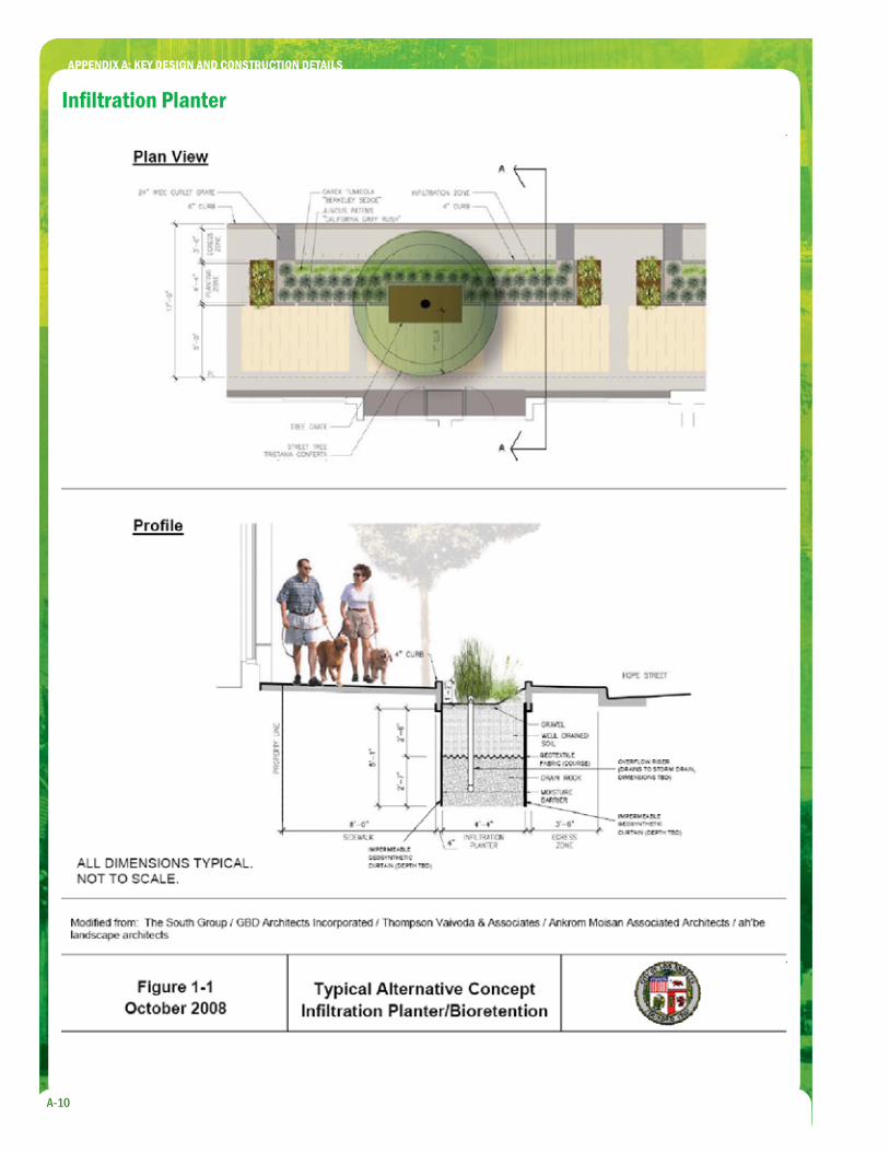
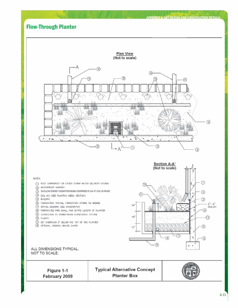
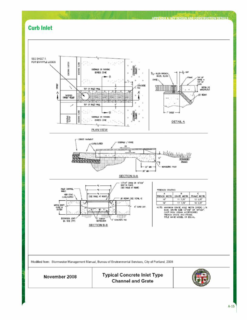
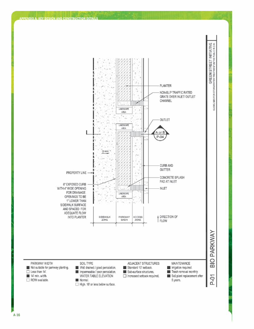
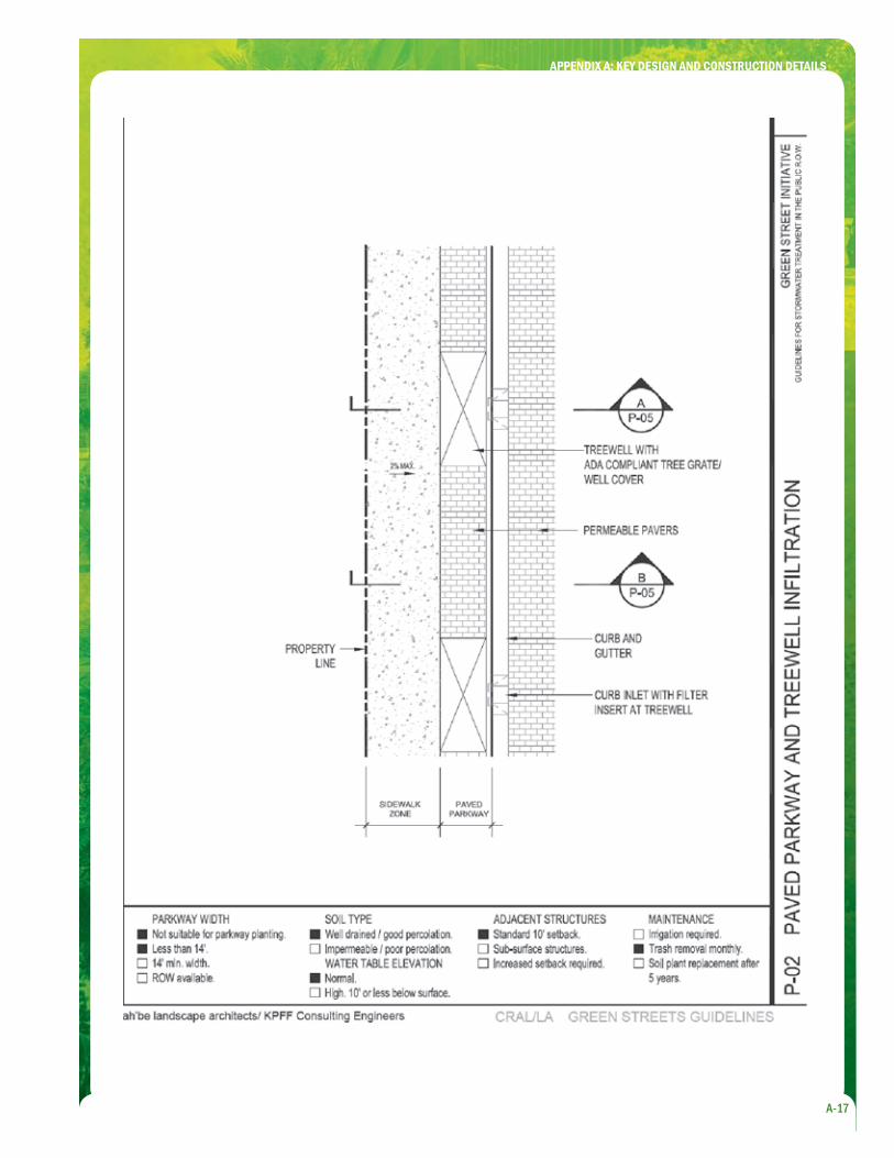
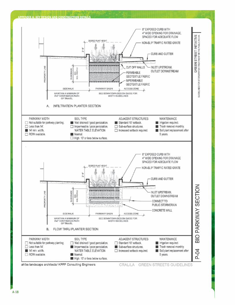
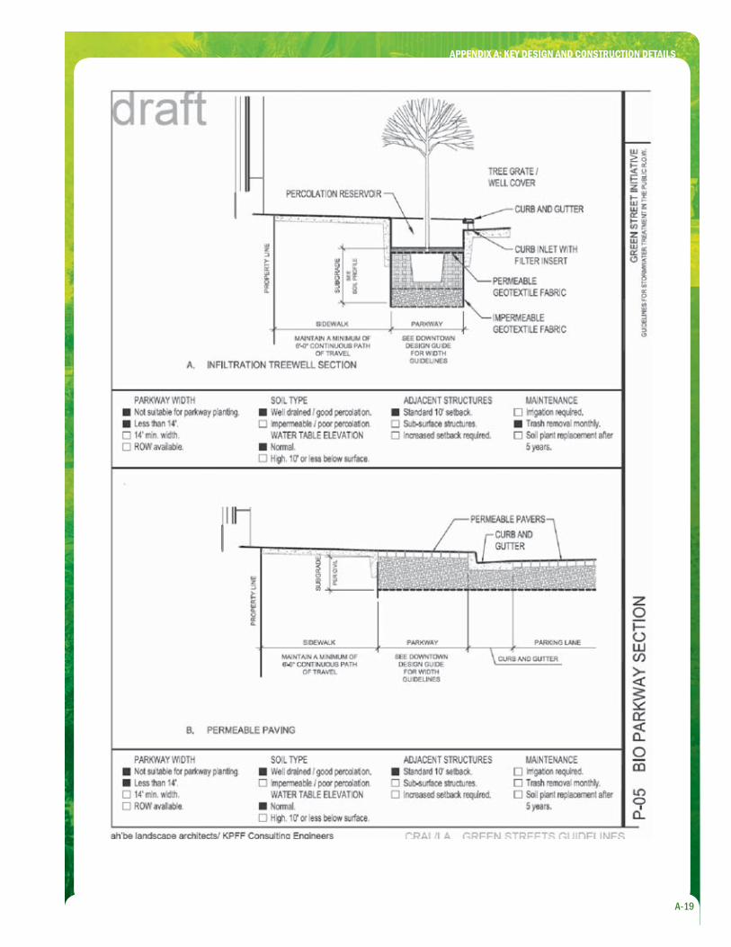
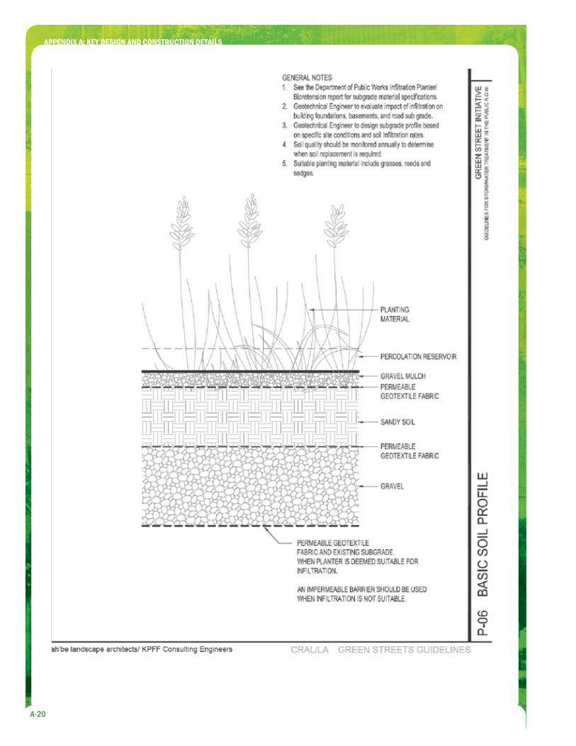
DrawingsThe following pages show cross-sections and plan view drawings provide typical design and construction details for the green streets and parking lots design strategies described in Section 2 of this document. These include tree canopy, vegetated swale, infi ltration/fl ow-through planter, pervious paving, planter box, infi ltration trench, stormwater curb extension, and curb inlet. The City of Los Angeles provides these as examples, rather than templates.
APPENDIX A: KEY DESIGN AND CONSTRUCTION DETAILS
A-9
Vegetated Swale
APPENDIX A: KEY DESIGN AND CONSTRUCTION DETAILS
A-10
Infi ltration Planter
APPENDIX A: KEY DESIGN AND CONSTRUCTION DETAILS
A-11
Flow-Through Planter
APPENDIX A: KEY DESIGN AND CONSTRUCTION DETAILS
A-12
Pervious Concrete/Asphalt
Typical Porous Paver Recycled Rubber Sidewalk Paving
Reinforced Grass Paving
APPENDIX A: KEY DESIGN AND CONSTRUCTION DETAILS
A-13
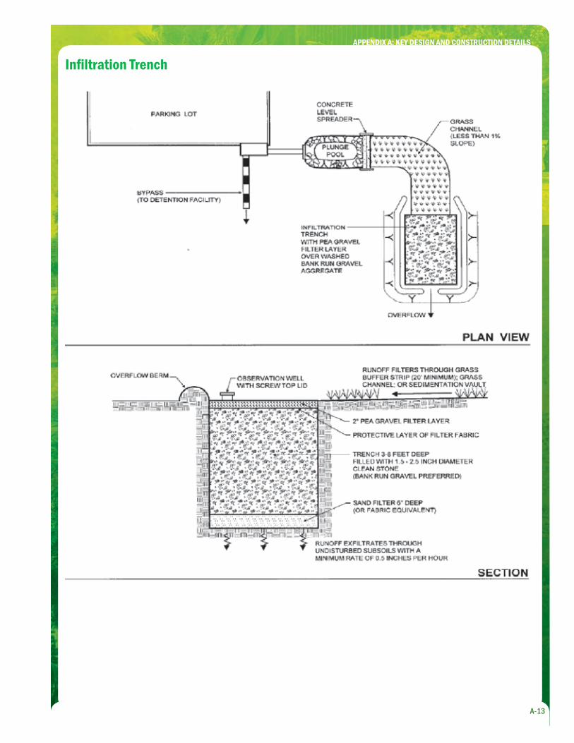
Infi ltration Trench
APPENDIX A: KEY DESIGN AND CONSTRUCTION DETAILS
A-14
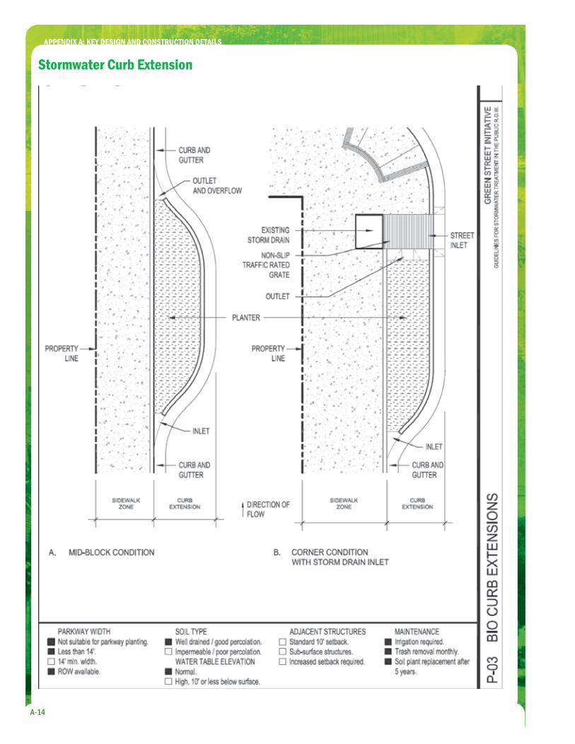
Stormwater Curb Extension
APPENDIX A: KEY DESIGN AND CONSTRUCTION DETAILS
A-15
Curb Inlet
APPENDIX A: KEY DESIGN AND CONSTRUCTION DETAILS
A-16
APPENDIX A: KEY DESIGN AND CONSTRUCTION DETAILS
A-17
APPENDIX A: KEY DESIGN AND CONSTRUCTION DETAILS
A-18
APPENDIX A: KEY DESIGN AND CONSTRUCTION DETAILS
A-19
APPENDIX A: KEY DESIGN AND CONSTRUCTION DETAILS
A-20

B-1
CITY OF LOS ANGELES STANDARD URBAN STORMWATER
MITIGATION PLAN INFILTRATION REQUIREMENTS & GUIDELINES
Appendix
BBackgroundSince the enactment of the Clean Water Act in 1987 and the adoption of the fi rst County of Los Angeles, National Pollutant Discharge Elimination System (NPDES) permit in 1990, it has been the intent of the Regional Water Quality Control Board (RWQCB) to minimize the impacts of storm water and urban runoff on the receiving water bodies by reducing the amount of storm water runoff. To this end, the NPDES permit requires that permittees establish regulations and policies to maximize the percentage of pervious surfaces to allow percolation of storm water into the ground and to minimize the quantity of storm water directed to impervious surfaces and the municipal separate storm sewer system (MS4). As such, the City of Los Angeles, Department of Public Works, Bureau of Sanitation, Watershed Protection Division, has established these infi ltration guidelines which delineate the requirements and limitations of storm water infi ltration and specify the order of preference for providing Standard Urban Stormwater Mitigation Plan (SUSMP) improvements as required by the NPDES permit.
Prioritization of BMP SelectionThe order of priority specifi ed below shall be followed in determining the appropriate type of SUSMP improvement for the project site.
Infi ltration Systems (Design based on the volume of storm water)1.
Bio-Filtration/Retention Systems (Design based on fl ow of 2. storm water)
Storm Water Capture and Re-Use (Optional. Subject to County Health 3. Dept approval)
Mechanical/Hydrodynamic Units4.
Combination of Any of the Above5.
Infi ltration systems are the fi rst priority type of SUSMP improvements as they provide for percolation and infi ltration of the storm water into the ground, which not only reduces the volume of storm water runoff entering into the MS4, but in some cases, can contribute to groundwater recharge.
If storm water infi ltration is not possible based on one or more of the following project site conditions listed below, the developer shall utilize the next type of SUSMP improvement in the order specifi ed above.
B-1
The NPDES permit requires that permittees establish regulations and policies to maximize the percentage of pervious surfaces to allow percolation of storm water into the ground and to minimize the quantity of storm water directed to impervious surfaces and the municipal separate storm sewer system (MS4).

B-2
Infi ltration RestrictionsIn most cases, project sites containing any one of the following conditions shall not be required to utilize infi ltration as part of their drainage system.
Building sites located in the City of Los Angeles 1. designated “Landslide” or “Hillside Grading” areas as specifi ed by the Department of City Planning’s Zone Information and Map Access System (ZIMAS).
Sites with shallow, low permeability or impervious 2. soils (silt, clay or bedrock) within 5 feet of existing grade.*
Sites with groundwater within 10 feet of existing 3. grade.*
Site soils with a moderate or high potential for 4. liquefaction.*
Sites with a slope steeper than 20% (5:1, horizontal 5. to vertical) as determined by the City of Los Angeles, Department of Building and Safety.
Sites with soil and/or groundwater 6. contamination.**
Sites with existing or removed underground storage 7. tanks. **
Locations consisting of heavy industrial uses such 8. as uses specifi ed in the “M” zones of the L.A. City Planning and Zoning code, including but not limited to vehicle or equipment maintenance yards, hazardous material storage, slaughter houses, etc.
* Soil type, depth of groundwater, and liquefaction potential of the project site shall be documented by an approved geotechnical report signed by a California Certifi ed Engineering Geologist or Geotechnical Engineer. See note at bottom of this document for geotechnical report requirements.
** The presence of soil and/or groundwater contamination and/or the presence of existing or removed underground storage tanks shall be documented by California Environmental Quality Act (CEQA) or National Environmental Policy Act (NEPA) environmental reports, approved geotechnical reports, permits on fi le with the City, or a review of the State of California’s Geotracker website.
If the project site is a good candidate for storm water infi ltration, the following requirements and guidelines shall be adhered to for the design of the infi ltration system.
Infi ltration RequirementsMinimum site soil percolation rate shall be 0.5 inches 1. per hour. Soils with a percolation rate of less than 0.5 in/hr may utilize a bio-fi ltration system that includes an under drain system to prevent extended ponding.
The minimum distance between the bottom of the 2. infi ltration trench to the existing groundwater level shall be 10 feet.
The setback of the infi ltration system from adjacent 3. private property lines shall be a minimum of 10 feet. Where subterranean walls or deep basements exist on the adjacent property, a greater setback or deeper infi ltration system may be required.
Infi ltration trenches shall be set back from any 4. building or structure a minimum of 10 feet or a minimum distance as specifi ed by the project geotechnical engineer and/or structural engineer of record or as required by the Department of Building and Safety.
An overfl ow drain that conducts the overfl ow 5. drainage to the street, per the requirements of Chapter 70 of the Los Angeles City Building Code, shall be provided for all infi ltration systems.
To determine water levels and to demonstrate 6. adequate functionality or maintenance needs, an observation well consisting of a vertical, 4 to 6-inch diameter PVC, perforated pipe shall be installed within the infi ltration system. The well shall terminate at the ground surface with a lockable, removable cap.
Infi ltration systems shall be constructed to prevent 7. infi ltration of water into fi ll material.
Infi ltration systems located in the Valley District 8. region of the City will be required to be approved by the Upper Los Angeles River Area Watermaster.
Geotechnical Report RequirementsAs determined by the City of Los Angeles, Department of Building and Safety, Grading Division, a geotechnical report may be required for projects that will incorporate infi ltration as part of the drainage system. Geotechnical reports shall be signed by a professional Geotechnical or Civil Engineer licensed in the State of California and/or a Certifi ed Engineering Geologist.Where Building and Safety determines that a geotechnical report is required, the report shall be reviewed and approved by the Grading Division and shall contain the following information/recommendations:
APPENDIX B: CITY OF LOS ANGELES, SUSMP INFILTRATION REQUIREMENTS & GUIDELINES

B-3
Site soil classifi cations in accordance with the a. Unifi ed Soil Classifi cation System.
Potential for liquefaction of site soils.b.
Depth of the ground water level at the project site.c.
Infi ltration rate and specifi cation of test method and d. procedures used to determine the infi ltration rate.
Analysis of the potential that perched water e. conditions could be created by the operation of the infi ltration system.
Statement regarding the effects of infi ltration on f. foundation settlement.
Statement regarding the effects of infi ltration on g. hydrostatic pressure.
Infi ltration Trench Sizing and Design GuidelinesAn infi ltration trench consists of a long, channel area in the ground composed of gravel and rock for detention of storm water prior to infi ltration into the ground. Runoff is stored in the void space between the rocks and infi ltrates through the bottom and sides of the trench into the soil matrix.
The following guidelines shall be implemented for the design of infi ltration trenches:
Provide a pre-screening method as part of the 1. infi ltration system in order to reduce the sediment load in the infi ltrating storm water to reduce clogging of the infi ltration system.
Examples of pre-screening methods include:
Vegetated planter with soil placed directly above a. gravel of infi ltration trench.
Grass swales conducting fl ow from impervious b. areas to infi ltration trench.
Catch basin fi lter inserts for fl ow conducted through c. a catch basin to infi ltration trench.
Roof down spout fi lters for storm water fl owing d. directly from down drain spouts into an infi ltration trench.
Hydrodynamic separators.e.
Oil absorbent socks.f.
Specify rock size to be between 3/4-inch to 3-inches 2. in diameter.
Provide a non-woven geo-textile fabric on all sides 3. and bottom of the trench.
The depth of the infi ltration trench shall be a 4. minimum of 2 feet .
Determine the size of the infi ltration trench using 5. the following equations:
D = (T x I) / (12 x F x VR)
Am = WQV / D
Where:D = Trench Depth (ft)
T = Drawdown Time (hours) which is assumed to be 48 hours
I = Infi ltration Rate (inches/hour)
F = Infi ltration Factor of Safety - to be as follows:
Without site specifi c boring and infi ltration tests, • use F = 10
With site specifi c borings, but no infi ltration • tests, use F = 6
With site specifi c infi ltration test, but no borings, • use F = 5
With both site specifi c boring and infi ltration • test, use F = 3
VR = Void Ratio (use 0.40 for gap graded gravel)
Am = Minimum Surface Area of the infi ltration trench (ft2)
WQV = Storm Water Runoff Quantity Volume (ft3)
Note: Infi ltration rates shall be determined by in-ground, site specifi c infi ltration tests or can be based on laboratory tests conducted on soil samples collected during the exploratory work for a site specifi c geotechnical report.
Where no site specifi c borings and/or no percolation test results are provided, the developer may provide information on the general soil characteristics of the project site based upon a previous geotechnical report on fi le with the Department of Building and Safety for an adjacent property within one-quarter (1/4) mile of subject site. Percolation rates can be based on the soil types specifi ed by the site specifi c geotechnical reports or the reports of adjacent lots as indicated above, or may be determined by a site specifi c percolation test.
APPENDIX B: CITY OF LOS ANGELES, SUSMP INFILTRATION REQUIREMENTS & GUIDELINES
C-1
GUIDELINES FOR STORM WATER INFILTRATION
Appendix
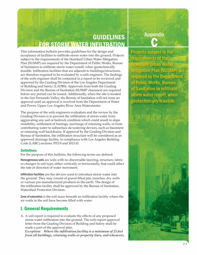
CThis information bulletin provides guidelines for the design and acceptance of facilities to infi ltrate storm water into the ground. Projects subject to the requirements of the Standard Urban Water Mitigation Plan (SUSMP) are required by the Department of Public Works, Bureau of Sanitation to infi ltrate storm water runoff, when geotechnically feasible. Infi ltration facilities that are adjacent to buildings/structures, are therefore required to be evaluated by a soils engineer. The fi ndings of the soils engineer shall be contained in a report to be reviewed and approved by the Grading Division of the Los Angeles Department of Building and Safety (LADBS). Approvals from both the Grading Division and the Bureau of Sanitation (SUSMP clearance) are required before any permit can be issued. Additionally, when the site is located in the San Fernando Valley, the Bureau of Sanitation will not issue an approval until an approval is received from the Department of Water and Power, Upper Los Angeles River Area Watermaster.
The purpose of the soils engineers evaluation and the review by the Grading Division is to prevent the infi ltration of storm water from aggravating any soil or bedrock condition which could result in slope instability, settlement of footings, surcharge of retaining walls, or from contributing water to subsurface de-watering devices, such as basement or retaining wall backdrains. If approval by the Grading Division and Bureau of Sanitation, the infi ltration structure will be considered as an approved drainage facility, in compliance with Los Angeles Building Code (LABC) sections 7013.9 and 1013.10.
Defi nitionsFor the purpose of this bulletin, the following terms are defi ned:Homogeneous soils are soils with no discernable layering, structure, fabric or changes in soil type, either vertically or horizontally, that could affect the rate of direction of water movement.
Infi ltration facilities are the devices used to introduce storm water into the ground. They may consist of gravel fi lled pits, trenches, dry wells or various pre-manufactured products in the earth. The design of the infi ltration facility shall be approved by the Bureau of Sanitation, Watershed Protection Division.
Zone of saturation is the soil mass beneath an infi ltration facility where the air voids in the soil have become fi lled with water.
I. General RequirementsA soil report is required to evaluate the effects of any proposed A. storm water infi ltration into the ground. The soils report approval letter from the Grading Division of Building and Safety shall be made a part of the approval plan.Exception: Where the infi ltration facility is a minimum of 25 feet from all buildings, retaining walls or property lines, and whenever,
C-1
Projects subject to the requirements of the Standard Urban Water Mitigation Plan (SUSMP) are required by the Department of Public Works, Bureau of Sanitation to infi ltrate storm water runoff, when geotechnically feasible.

C-2
there is a basement beneath the building, the horizontal distance between a building and the infi ltration facility is greater than 25 feet plus the depth of the basement, a soil report is not required.
Storm water infi ltration is not allowed in the B. Hillside Grading Area as designated on the Bureau of Engineering Basic Grid Map No. A-13372. An exception may be made if it can be clearly demonstrated that the infi ltrated storm water can not possibly contribute to any groundwater that may affect the stability of slopes, either on, adjacent to, or distant from the site.
Storm water fi ltration is not allowed on any site C. where the water may saturate soils that are subject to liquefaction.
II Minimum Design Requirements- The following design guidelines shall be considered as minimum requirements on sites where infi ltration is found acceptable by the soils engineer and approved by the Grading Division. Subject to the fi ndings of the soils investigation report, additional setbacks or design considerations may be required.
- Water infi ltration into the ground must occur a minimum of 10 feet above the groundwater table, unless otherwise approved by the Bureau of Sanitation.
- The distance between the infi ltration facility and the adjacent private property line shall be a minimum of 10 feet. Where subterranean walls or deep basements exist on the adjacent property, a greater setback or deeper infi ltration system may be required to comply with the criteria in this bulletin.
- Foundations shall be set back a minimum of 10 feet from the infi ltration facility and the bottom of the footing shall be a minimum of 10 feet from the expected zone of saturation. Note: the boundary of the zone of saturation in homogenous soils may be assumed to be project downward from the top of the permeable portion of the infi ltration facility at gradient of 1:1 or fl atter, as determined by the soil engineer.
- Infi ltration facilities shall not be located on a slope with a gradient greater than 20% (5:1 horizontal to vertical).
- Infi ltration facilities shall not be located so that soils supported by retaining and basement walls are not saturated.
-Dry wells adjacent to buildings shall be cased to a depth where the potential saturation zone is at least 10 feet from any footing. The annular space around the casing shall be sealed to prevent water from raising up the outside of the casing.
- No infi ltration facility shall be placed to infi ltrate water into fi ll material.
- Grassy swales shall be located a minimum of 5 feet from any building and property line and should drain at a minimum of 2% gradient.
- The infi ltration facility shall be designed to overfl ow to the street in the event that the drainage capacity is exceeded or in case of future failure to adequately infi ltrate.
- Porous concrete or similar permeable hardscape materials are allowed to be used in the Hillside Grading Area, only where they will be subject to incidental rainfall and not where they would be subject to a concentrated fl ow of water such as from roof downspouts. Any hardscape design that impedes the fl ow of water over the ground surface is not acceptable.
III. Soil REPORT CONTENTWhen required by Section IA, the soils engineer is to determine whether the site is suitable or unsuitable for the proposed infi ltration facility. The soils report shall identify any soil/geologic conditions that could be adversely affected by water or that could infl uence the movement of water and make appropriate recommendations. The report shall be submitted to the Grading Division for review and approval prior to issuance of any permit.
A. Reports for Sites Suitable for Infi ltrationThe soils report shall contain an opinion that the site is suitable for the proposed infi ltration facility without increasing the potential for settlement of structures or adversely affecting retaining/basement wall, located either on or adjacent to the subject site. The report shall contain the following:
- Map showing the locations of the proposed storm water infi ltration facility and all adjacent structures, either on or adjacent to the site.
- A fi nding as to the potential for creating perched water conditions that may adversely affect structures.
- A fi nding as to the infl uence of the infi ltration facility on the existing retaining walls. Infi ltration facilities shall be located so that soil supported by retaining/basement walls is not saturated.
APPENDIX C: GUIDELINES FOR STORMWATER INFILTRATION
C-3
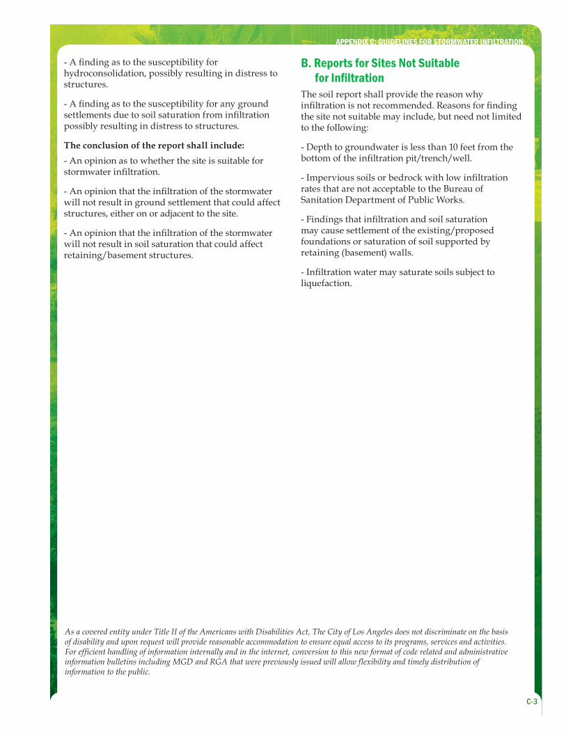
- A fi nding as to the susceptibility for hydroconsolidation, possibly resulting in distress to structures.
- A fi nding as to the susceptibility for any ground settlements due to soil saturation from infi ltration possibly resulting in distress to structures.
The conclusion of the report shall include:
- An opinion as to whether the site is suitable for stormwater infi ltration.
- An opinion that the infi ltration of the stormwater will not result in ground settlement that could affect structures, either on or adjacent to the site.
- An opinion that the infi ltration of the stormwater will not result in soil saturation that could affect retaining/basement structures.
B. Reports for Sites Not Suitable for Infi ltration
The soil report shall provide the reason why infi ltration is not recommended. Reasons for fi nding the site not suitable may include, but need not limited to the following:
- Depth to groundwater is less than 10 feet from the bottom of the infi ltration pit/trench/well.
- Impervious soils or bedrock with low infi ltration rates that are not acceptable to the Bureau of Sanitation Department of Public Works.
- Findings that infi ltration and soil saturation may cause settlement of the existing/proposed foundations or saturation of soil supported by retaining (basement) walls.
- Infi ltration water may saturate soils subject to liquefaction.
APPENDIX C: GUIDELINES FOR STORMWATER INFILTRATION
As a covered entity under Title II of the Americans with Disabilities Act, The City of Los Angeles does not discriminate on the basis of disability and upon request will provide reasonable accommodation to ensure equal access to its programs, services and activities. For effi cient handling of information internally and in the internet, conversion to this new format of code related and administrative information bulletins including MGD and RGA that were previously issued will allow fl exibility and timely distribution of information to the public.