Embed Size (px)
DESCRIPTION
Specification
Citation preview
7/17/2019 Graviner MK6 Oil Mist Detector
http://slidepdf.com/reader/full/graviner-mk6-oil-mist-detector 1/4
G R A V I N E RM k 6 O i l M i s t D e t e c t i o n S y s t e m
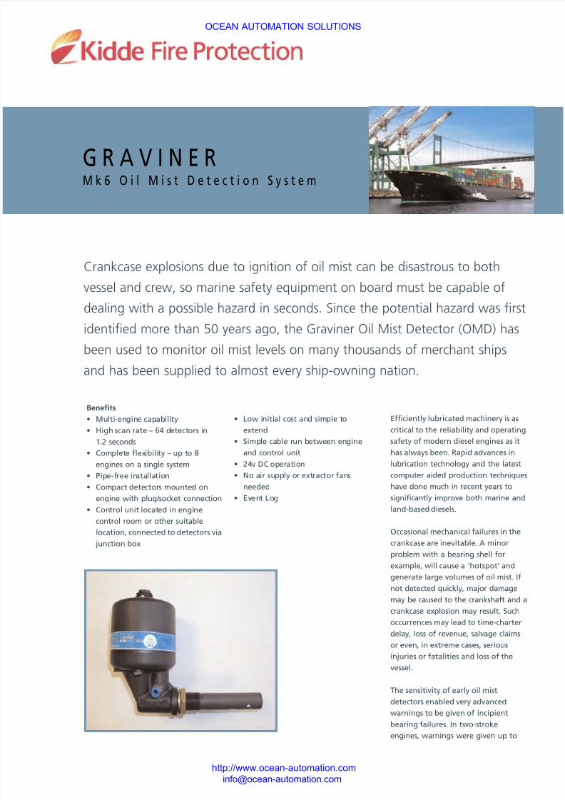
Crankcase explosions due to ignition of oil mist can be disastrous to both
vessel and crew, so marine safety equipment on board must be capable of
dealing with a possible hazard in seconds. Since the potential hazard was first
identified more than 50 years ago, the Graviner Oil Mist Detector (OMD) has
been used to monitor oil mist levels on many thousands of merchant ships
and has been supplied to almost every ship-owning nation.
• Low initial cost and simple toextend
• Simple cable run between engine
and control unit
• 24v DC operation
• No air supply or extractor fans
needed
• Event Log
Efficiently lubricated machinery is ascritical to the reliability and operating
safety of modern diesel engines as it
has always been. Rapid advances in
lubrication technology and the latest
computer aided production techniques
have done much in recent years to
significantly improve both marine and
land-based diesels.
Occasional mechanical failures in the
crankcase are inevitable. A minor
problem with a bearing shell for
example, will cause a ‘hotspot’ and
generate large volumes of oil mist. If
not detected quickly, major damage
may be caused to the crankshaft and a
crankcase explosion may result. Such
occurrences may lead to time-charter
delay, loss of revenue, salvage claims
or even, in extreme cases, serious
injuries or fatalities and loss of the
vessel.
The sensitivity of early oil mist
detectors enabled very advancedwarnings to be given of incipient
bearing failures. In two-stroke
engines, warnings were given up to
Benefits
• Multi-engine capability• High scan rate – 64 detectors in
1.2 seconds
• Complete flexibility – up to 8
engines on a single system
• Pipe-free installation
• Compact detectors mounted on
engine with plug/socket connection
• Control unit located in engine
control room or other suitable
location, connected to detectors via
junction box
OCEAN AUTOMATION SOLUTIONS
http://www.ocean-automation.com
7/17/2019 Graviner MK6 Oil Mist Detector
http://slidepdf.com/reader/full/graviner-mk6-oil-mist-detector 2/4
G R A V I N E R M k 6 O I L M I S T D E T E C T O R2
5-6 hours before any problems
became apparent. As engine design
improved, power outputs and bearing
loads increased and tolerances to
failure rapidly decreased.
To keep pace with these trends, oil
mist detector design improved in
terms of better sampling and faster
response times. The time has now
arrived where no further fundamental
improvements can be made to existing
system concepts, so a radical re-
appraisal of Oil Mist Detector
operating principles was required. The
Graviner Mk6 OMD is the result.
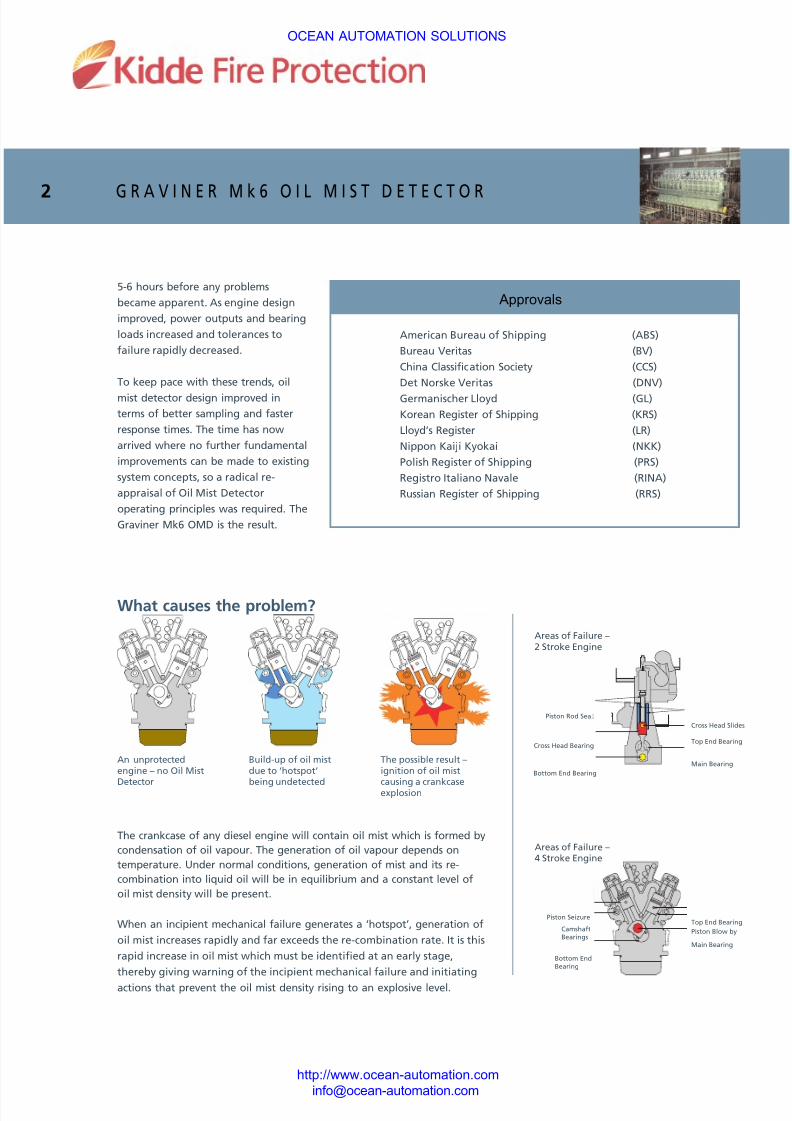
An unprotectedengine – no Oil Mist
Detector
Build-up of oil mistdue to ‘hotspot’
being undetected
The possible result –ignition of oil mist
causing a crankcaseexplosion
American Bureau of Shipping (ABS)
Bureau Veritas (BV)
China Classification Society (CCS)
Det Norske Veritas (DNV)
Germanischer Lloyd (GL)
Korean Register of Shipping (KRS)
Lloyd’s Register (LR)
Nippon Kaiji Kyokai (NKK)
Polish Register of Shipping (PRS)
Registro Italiano Navale (RINA)
Russian Register of Shipping (RRS)
The crankcase of any diesel engine will contain oil mist which is formed by
condensation of oil vapour. The generation of oil vapour depends on
temperature. Under normal conditions, generation of mist and its re-
combination into liquid oil will be in equilibrium and a constant level of
oil mist density will be present.
When an incipient mechanical failure generates a ‘hotspot’, generation of
oil mist increases rapidly and far exceeds the re-combination rate. It is this
rapid increase in oil mist which must be identified at an early stage,
thereby giving warning of the incipient mechanical failure and initiating
actions that prevent the oil mist density rising to an explosive level.
Areas of Failure –2 Stroke Engine
Piston Rod Seal
Cross Head Slides
Top End Bearing
Main Bearing
Bottom End Bearing
Cross Head Bearing
Areas of Failure –4 Stroke Engine
Piston SeizureTop End Bearing
Piston Blow by
Main Bearing
CamshaftBearings
Bottom EndBearing
What causes the problem?
OCEAN AUTOMATION SOLUTIONS
http://www.ocean-automation.com
Approvals
7/17/2019 Graviner MK6 Oil Mist Detector
http://slidepdf.com/reader/full/graviner-mk6-oil-mist-detector 3/4
G R A V I N E R M k 6 O I L M I S T D E T E C T O R3
System Description
The Mk6 OMD is an analogue addressable oil mist detection system, capable of
monitoring up to 64 detector heads fitted on up to 8 engines. This is achieved
without sample pipes and with minimum cabling. Each detector head monitors a
single crankspace and is a stand-alone device. When assigned a unique address
and supplied with 24V DC it gathers oil mist density data and converts it to a
digital signal for transmission via the data cable to the control unit.
The control unit can be configured to monitor from one to eight engines.
Detector addresses are identified and associated with the appropriate engine.
Deviation levels, average alarm levels and alarm output requirements are all set
from the control unit.
The large LCD display shows, on demand, the signal from each detector and
indicates the average oil mist level for each engine. In the event of an alarm,
the display immediately shows the oil mist signals for the relevant engine. It also
enables the individual readings of each detector and the average on an engine
to be displayed on demand and automatically under alarm conditions. In the
event of a detector fault, that detector can be isolated without affecting the
other detectors on the engine. The system will continue to operate while thefaulty detector is replaced.
Existing Systems
Oil mist detection requires a means of
obtaining mist samples for
measurement. This has always been
achieved by means of a system of
sample pipes fitted to the side of the
engine. Later systems with individual
detector heads still required some
pipework. In addition, internal or
external fans or pneumatic air movers
were required to obtain the samples
for analysis. Engine builders and
owners have for some time called for
a more flexible approach: A system
which is simple to install, with no
pipework and with no controls in the
engine room. The Graviner Mk6 Oil
Mist Detection System meets all these
requirements.
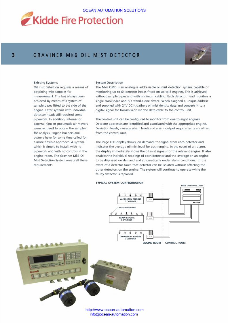
TYPICAL SYSTEM CONFIGURATION
ENGINE ROOM CONTROL ROOM
AUXILIARY ENGINE
5 CYLINDER
MK6 CONTROL UNIT
J BOX
J BOX
MK6 OMD
J BOX
MAIN ENGINE
7 CYLINDER
AUXILIARY ENGINE
5 CYLINDER
DETECTOR HEADS
OCEAN AUTOMATION SOLUTIONS
http://www.ocean-automation.com
7/17/2019 Graviner MK6 Oil Mist Detector
http://slidepdf.com/reader/full/graviner-mk6-oil-mist-detector 4/4
G R A V I N E R M k 6 O I L M I S T D E T E C T O R4
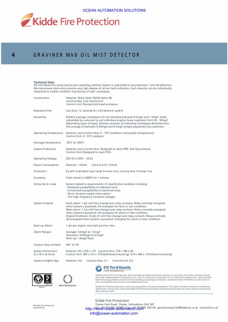
Technical DataOil mist detection using well proven sampling method. System is selectable to scan between 1 and 64 detectors.Microprocessor electronics ensures very high degree of active fault indication. Each detector can be individuallymeasured to enable condition monitoring of each crankspace.
Construction Detector: Black Zytel 70G30 Nylon 66Junction Box: Cast AluminiumControl Unit: Painted mild steel enclosure
Response time Less than 1.2 seconds for a 64 detector system.
Sensitivity Detects average crankspace oil mist densities between 0.3mg/l and 1.3mg/l. Easilyadjustable by customer to suit individual engine (lower explosion limit 30 - 50mg/ldepending upon oil type). Detects variation of individual crankspace densities fromthe average of between 0.05mg/l and 0.5mg/l (simple adjustment by customer).
Operating Temperature Detector and Junction Box: 0 - 70°C (ambient and sample temperature)Control Unit: 0 - 55°C ambient.
Strorage temperature -20°C to +60°C
System Protection Detector and Junction Box: Designed to meet IP65. Salt fog immune.Control Unit: Designed to meet IP32.
Operating Voltage 24V DC (+30% -25%)
Power Consumption Detector: 116mA Control Unit: 215mA
Protection By self re-settable fuse inside Control Unit; Junction Box 4.0 amp fuse
Insulation Flash tested to 2000V for 1 minute
Immunity to noise System tested to requirements of classification societies including:- Radiated susceptibility to radiated noise- Conducted susceptibility to electrical noise- Short duration supply interruption- 1kV high frequency transient voltages.
System Outputs Fault alarm: 1 set volt-free change-over relay contacts. Relay normally energisedwhen system is powered. De-energises for fault or test condition.Main alarm: 1 set volt-free change-over relay contacts. Relay normally energisedwhen system is powered. De-energises for alarm or test condition.Engine shutdown: 8 sets of volt-free change-over relay contacts. Relays normallyde-energised when system is powered. Energises for alarm or test condition.
Back-up Alarm: 1 set per engine mounted junction box.
Alarm Ranges: Average: 0.3mg/l to 1.3mg/lDeviation: 0.05mg/l to 0.5mg/lBack-up: 1.6mg/l fixed
Output relay contacts 30V 1A DC
System dimensions Detector: 95 x 205 x 175 Junction Box: 318 x 186 x 90(L x W x H) (mm) Control Unit: 500 x 313 x 118 (Bulkhead mounting) 619 x 369 x 118 (Panel mounting)
System weights (kg) Detector: 0.6 Junction Box: 2.7 Control Unit: 6.6
© Kidde Fire Protection6257/ 4 07.09
Kidde Fire ProtectionThame Park Road, Thame, Oxfordshire OX9 3RTTel: +44 (0)1844 265003 Fax: +44 (0)1844 265156 [email protected] www.kfp.co.uk
Kidde Fire Protection operates a continuous programme of product development. The right is therefore reserved to modify anyspecification without prior notice and Kidde Fire Protection should be contacted to ensure that the current issues of all technicaldata sheets are used.
Kidde is part of UTC Fire & Security, which provides fire safety and security solutions to more than one million customers aroundthe world. Headquartered in Connecticut, U.S., UTC Fire & Security is a business unit of United Technologies Corp., which provideshigh technology products and services to the building and aerospace industries worldwide. More information can be found at
www.utcfireandsecurity.com and www.kiddeproducts.com.
OCEAN AUTOMATION SOLUTIONS
http://www.ocean-automation.com