Embed Size (px)
Citation preview
Grasshopper-ARCHICAD Live Connection 1.8 User Guide
for ARCHICAD 21
Available for Windows and MAC
last updated on August 28, 2017
GRAPHISOFT®Visit the GRAPHISOFT website at www.graphisoft.com for local distributor and product availability
information.
Grasshopper-ARCHICAD Live Connection 1.8 User Guide
Copyright © 2017 by GRAPHISOFT, all rights reserved. Reproduction, paraphrasing or translation without express prior written permission is strictly prohibited.
Trademarks
ARCHICAD® is a registered trademark of GRAPHISOFT. Rhinoceros® and Grasshopper® are registered trademarks of Robert McNeel & Associates.
All other trademarks are the property of their respective holders.
This tool is available free, from GRAPHISOFT only. Distribution of this tool through any other channel is prohibited.
Contents
Grasshopper-ARCHICAD Live Connection 1.8 User Guide 3
ContentsIntroduction ________________________________________________________ 4
Getting Started ______________________________________________________ 5
ARCHICAD Nodes ___________________________________________________ 10
ARCHICAD Parameter Nodes . . . . . . . . . . . . . . . . . . . . . . . . . . . . . . . . . . . . . . . . . . . . . . . . . . . . . . 12
The Synchronize Parameter . . . . . . . . . . . . . . . . . . . . . . . . . . . . . . . . . . . . . . . . . . . . . . . . . . . . . . . 15
The Settings Parameter and Settings Nodes . . . . . . . . . . . . . . . . . . . . . . . . . . . . . . . . . . . . . . . . . . 16
The Property Settings Node (Controlling Metadata) . . . . . . . . . . . . . . . . . . . . . . . . . . . . . . . . . . . 17
ARCHICAD Document Components . . . . . . . . . . . . . . . . . . . . . . . . . . . . . . . . . . . . . . . . . . . . . . . . . 20
ARCHICAD Design Components . . . . . . . . . . . . . . . . . . . . . . . . . . . . . . . . . . . . . . . . . . . . . . . . . . . . 23
ARCHICAD Reshape Components . . . . . . . . . . . . . . . . . . . . . . . . . . . . . . . . . . . . . . . . . . . . . . . . . . . 36
ARCHICAD Input Nodes . . . . . . . . . . . . . . . . . . . . . . . . . . . . . . . . . . . . . . . . . . . . . . . . . . . . . . . . . . . 37
Workflow Examples _________________________________________________ 44
Important Notes ____________________________________________________ 50
Accessing GDL Parameters of ARCHICAD Library Parts ______________________ 53
Introduction
Introduction
What is Grasshopper?
Grasshopper (GH) is a node-based algorithm editor integrated with Rhino modeling tools. Algorithms are used to describe logical relationships among design parameters that define the parametric model. Through algorithms, the user is able to establish a set of rules that define the sequence of operations, thus aiding the design process.
What is the purpose of the Grasshopper-ARCHICAD Live Connection tool?
The Grasshopper-ARCHICAD Live Connection offers a unique design workflow, using algorithms, which helps you explore a large number of design variations and create and fine-tune building details and structures - without exchanging files.
Key features and benefits
• Translate simple geometry created in Rhino into BIM construction elements
• Bi-directional connection – no need to export/import file for data exchange
• Dynamic (live) connection while editing
• Direct and simultaneous graphical feedback from both Rhino and ARCHICAD
Supported workflows
This set of tools enables Rhino/Grasshopper (GH) and ARCHICAD (AC) to communicate directly. Designers working in either Rhino/Grasshopper or ARCHICAD can utilize its functionality to their advantage. Users can start the design process in either work environment (AC or RH or GH). In each case, the user will select an original set of reference geometries to be manipulated via Grasshopper, or create it from scratch in Grasshopper.
• “Start with pure 3D geometry” workflow: Designers start with the design geometry using Rhino and Grasshopper. With the “GH-AC Connection” tool, they can dynamically generate a BIM model consisting of ARCHICAD construction elements, and update the resulting BIM model directly from Grasshopper.
• “Start with intelligent building elements” workflow: Designers start with the design in ARCHICAD and extend their AC toolbox with algorithmic design methods applied to AC elements. In this workflow, input reference geometries (reference points, curves and other parameters) are taken directly from ARCHICAD and used in Grasshopper, without interaction in Rhino.
Scope of the manual
This manual is intended to explain only the added functionality of creating ARCHICAD elements from Grasshopper. The general description of functionality of ARCHICAD, Grasshopper or Rhino is not in the scope of this manual. To acquire the necessary basic knowledge in these applications, please visit the following sites.
• Grasshopper Training Center: http://www.grasshopper3d.com/page/tutorials-1
• ARCHICAD Training Materials: http://www.graphisoft.com/learning/training_materials/
• Rhinoceros3D Learning Center: http://www.rhino3d.com/learn
Grasshopper-ARCHICAD Live Connection 1.8 User Guide 4
Getting Started
Getting Started
Install Add-Ons (Windows)
To achieve a connection between the ARCHICAD and Grasshopper applications, you must install a GRAPHISOFT extension: the Grasshopper – ARCHICAD Live Connection.
Important: ARCHICAD-Grasshopper Connection for Windows is available for AC 18, 19, 20 and 21. You should install the installer (MSI file) which corresponds to your version of ARCHICAD.
Before installing it, make sure that the latest version of Rhinoceros for Windows (Version 5 64-bit) and ARCHICAD (version 18, 19, 20 or 21) are both installed on your computer.
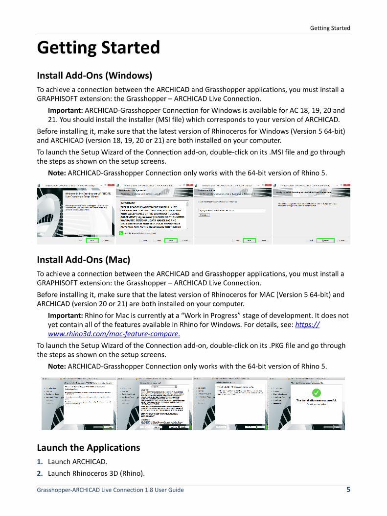
To launch the Setup Wizard of the Connection add-on, double-click on its .MSI file and go through the steps as shown on the setup screens.
Note: ARCHICAD-Grasshopper Connection only works with the 64-bit version of Rhino 5.
Install Add-Ons (Mac)
To achieve a connection between the ARCHICAD and Grasshopper applications, you must install a GRAPHISOFT extension: the Grasshopper – ARCHICAD Live Connection.
Before installing it, make sure that the latest version of Rhinoceros for MAC (Version 5 64-bit) and ARCHICAD (version 20 or 21) are both installed on your computer.
Important: Rhino for Mac is currently at a “Work in Progress” stage of development. It does not yet contain all of the features available in Rhino for Windows. For details, see: https://www.rhino3d.com/mac-feature-compare.
To launch the Setup Wizard of the Connection add-on, double-click on its .PKG file and go through the steps as shown on the setup screens.
Note: ARCHICAD-Grasshopper Connection only works with the 64-bit version of Rhino 5.
Launch the Applications
1. Launch ARCHICAD.
2. Launch Rhinoceros 3D (Rhino).
Grasshopper-ARCHICAD Live Connection 1.8 User Guide 5
Getting Started
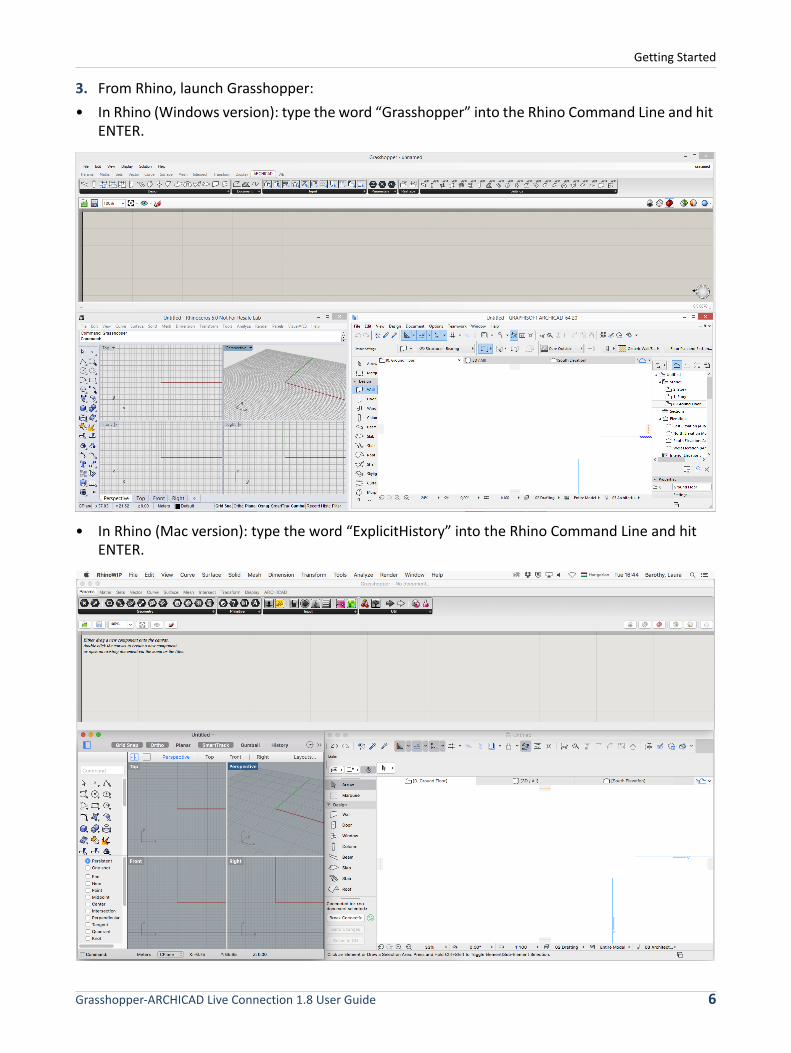
3. From Rhino, launch Grasshopper:
• In Rhino (Windows version): type the word “Grasshopper” into the Rhino Command Line and hit ENTER.
• In Rhino (Mac version): type the word “ExplicitHistory” into the Rhino Command Line and hit ENTER.
Grasshopper-ARCHICAD Live Connection 1.8 User Guide 6
Getting Started
Notes:
◦ Once all three applications are running, it is recommended to arrange the windows so that they do not overlap. (For ease of use, use multiple screens).
◦ To receive notifications and information from the add-ons, turn on the Status bar palette in ARCHICAD (Window > Palettes > Status bar).
Start the Connection
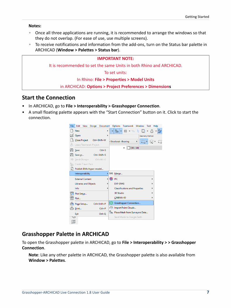
• In ARCHICAD, go to File > Interoperability > Grasshopper Connection.
• A small floating palette appears with the “Start Connection” button on it. Click to start the connection.
Grasshopper Palette in ARCHICAD
To open the Grasshopper palette in ARCHICAD, go to File > Interoperability > > Grasshopper Connection.
Note: Like any other palette in ARCHICAD, the Grasshopper palette is also available from Window > Palettes.
IMPORTANT NOTE:
It is recommended to set the same Units in both Rhino and ARCHICAD.
To set units:
In Rhino: File > Properties > Model Units
in ARCHICAD: Options > Project Preferences > Dimensions
Grasshopper-ARCHICAD Live Connection 1.8 User Guide 7

Getting Started
The palette contains 3 buttons:
• Start/Break Connection: Click to turn on/turn off the connection between Grasshopper and ARCHICAD.
• Send Changes: Updates Grasshopper about changes made in ARCHICAD. This button is active only when you are editing an ARCHICAD element referred to by the Grasshopper code via a Parameter Node (see the Parameter Nodes section below).
• Select in GH: In Grasshopper, selects the nodes which generated the elements currently selected in ARCHICAD. This button is active only if the current ARCHICAD selection includes at least one element generated by the Grasshopper code.
Notes:
◦ If the green icon is spinning, this indicates that the connection with Grasshopper is live, and ARCHICAD is now ready to send and receive information.
◦ The palette also tells you which currently opened Grasshopper document is connected to ARCHICAD.
ARCHICAD Tab in Grasshopper
In Grasshopper, a new “ARCHICAD” tab has appeared on Grasshopper's tab bar. The icons on this tab resemble those of ARCHICAD tools; they represent components, parameters and input nodes.
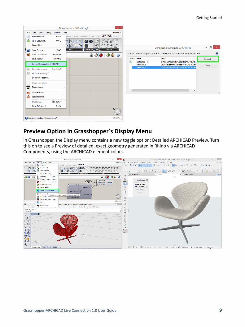
Command in Grasshopper’s File menu
In Grasshopper, a new command appears in the File menu: “Connect Document to ARCHICAD”. This command opens a dialog box: among the currently open Grasshopper files, choose the one that should communicate with ARCHICAD.
Grasshopper-ARCHICAD Live Connection 1.8 User Guide 8
Getting Started
Preview Option in Grasshopper’s Display Menu
In Grasshopper, the Display menu contains a new toggle option: Detailed ARCHICAD Preview. Turn this on to see a Preview of detailed, exact geometry generated in Rhino via ARCHICAD Components, using the ARCHICAD element colors.
Grasshopper-ARCHICAD Live Connection 1.8 User Guide 9
ARCHICAD Nodes
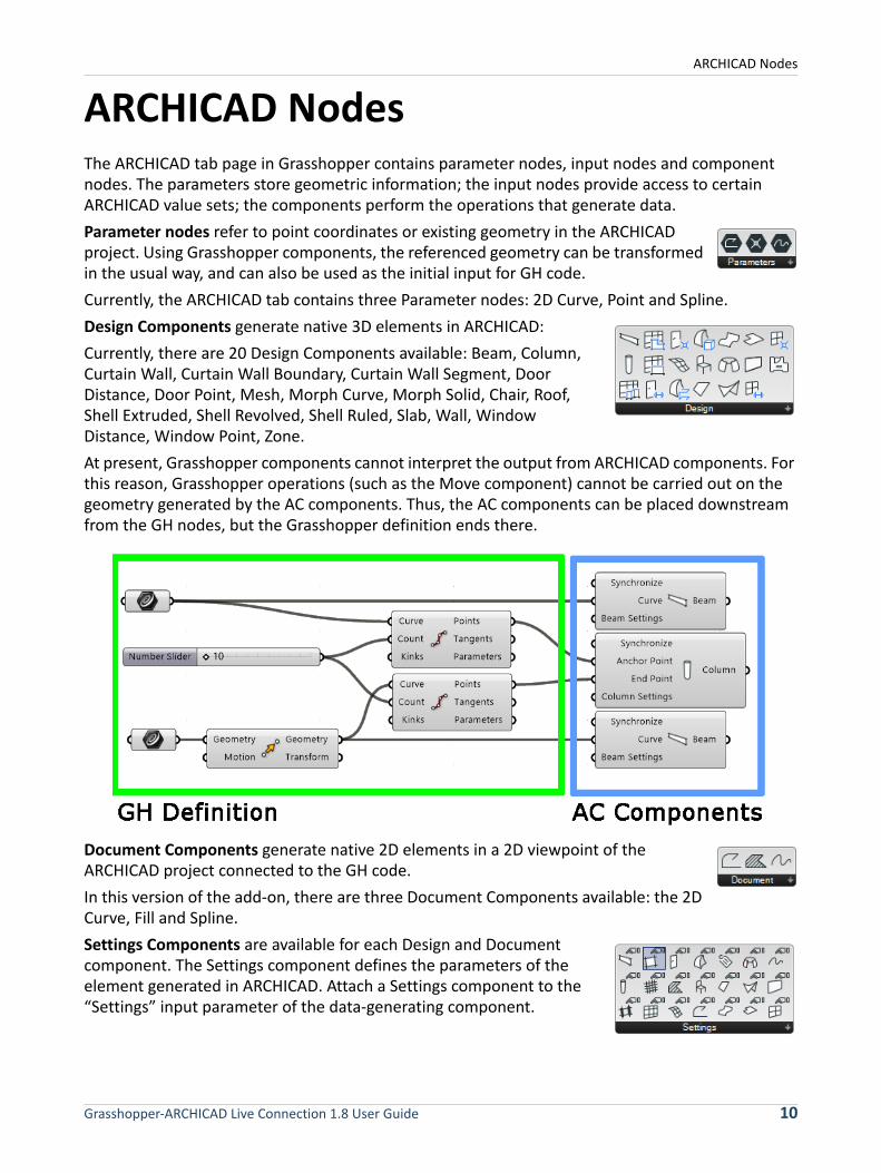
ARCHICAD NodesThe ARCHICAD tab page in Grasshopper contains parameter nodes, input nodes and component nodes. The parameters store geometric information; the input nodes provide access to certain ARCHICAD value sets; the components perform the operations that generate data.
Parameter nodes refer to point coordinates or existing geometry in the ARCHICAD project. Using Grasshopper components, the referenced geometry can be transformed in the usual way, and can also be used as the initial input for GH code.
Currently, the ARCHICAD tab contains three Parameter nodes: 2D Curve, Point and Spline.
Design Components generate native 3D elements in ARCHICAD:
Currently, there are 20 Design Components available: Beam, Column, Curtain Wall, Curtain Wall Boundary, Curtain Wall Segment, Door Distance, Door Point, Mesh, Morph Curve, Morph Solid, Chair, Roof, Shell Extruded, Shell Revolved, Shell Ruled, Slab, Wall, Window Distance, Window Point, Zone.
At present, Grasshopper components cannot interpret the output from ARCHICAD components. For this reason, Grasshopper operations (such as the Move component) cannot be carried out on the geometry generated by the AC components. Thus, the AC components can be placed downstream from the GH nodes, but the Grasshopper definition ends there.
Document Components generate native 2D elements in a 2D viewpoint of the ARCHICAD project connected to the GH code.
In this version of the add-on, there are three Document Components available: the 2D Curve, Fill and Spline.
Settings Components are available for each Design and Document component. The Settings component defines the parameters of the element generated in ARCHICAD. Attach a Settings component to the “Settings” input parameter of the data-generating component.
Grasshopper-ARCHICAD Live Connection 1.8 User Guide 10
ARCHICAD Nodes
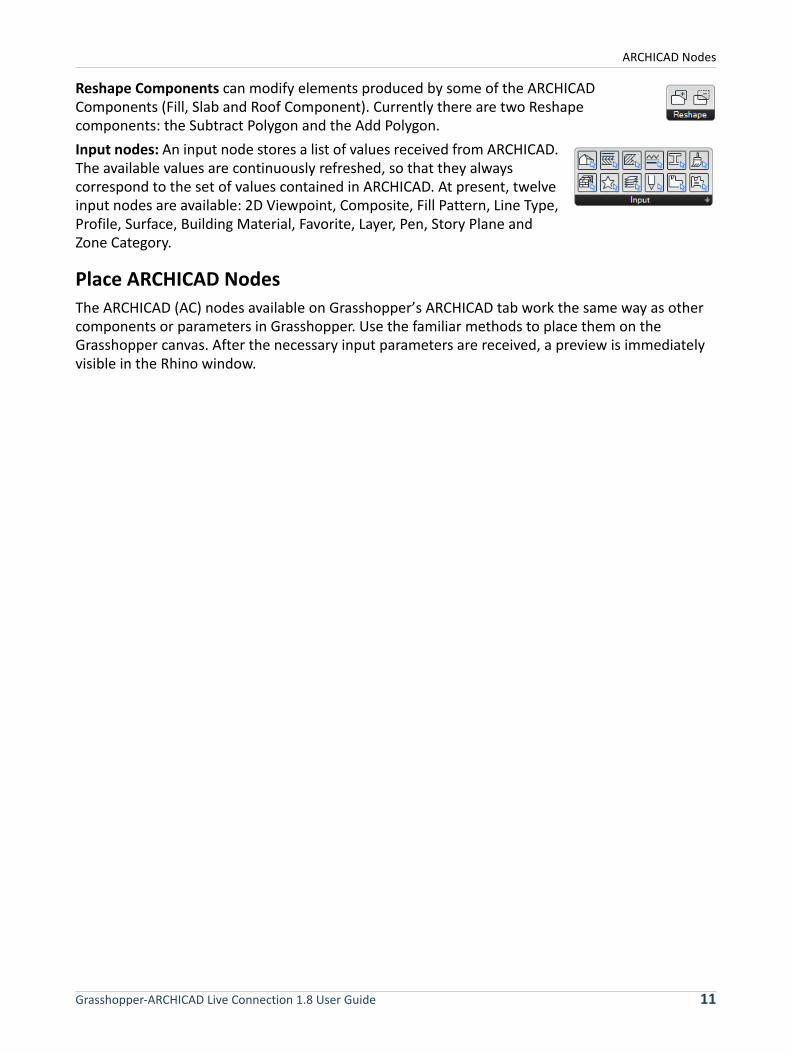
Reshape Components can modify elements produced by some of the ARCHICAD Components (Fill, Slab and Roof Component). Currently there are two Reshape components: the Subtract Polygon and the Add Polygon.
Input nodes: An input node stores a list of values received from ARCHICAD. The available values are continuously refreshed, so that they always correspond to the set of values contained in ARCHICAD. At present, twelve input nodes are available: 2D Viewpoint, Composite, Fill Pattern, Line Type, Profile, Surface, Building Material, Favorite, Layer, Pen, Story Plane and Zone Category.
Place ARCHICAD Nodes
The ARCHICAD (AC) nodes available on Grasshopper’s ARCHICAD tab work the same way as other components or parameters in Grasshopper. Use the familiar methods to place them on the Grasshopper canvas. After the necessary input parameters are received, a preview is immediately visible in the Rhino window.
Grasshopper-ARCHICAD Live Connection 1.8 User Guide 11
ARCHICAD Nodes
ARCHICAD Parameter NodesThe AC Parameter nodes refer to points or existing elements in the ARCHICAD project. AC Parameter nodes are an integral part of the Grasshopper code, because the Grasshopper code recognizes them as Geometry-type input data.
AC Point Parameter Node
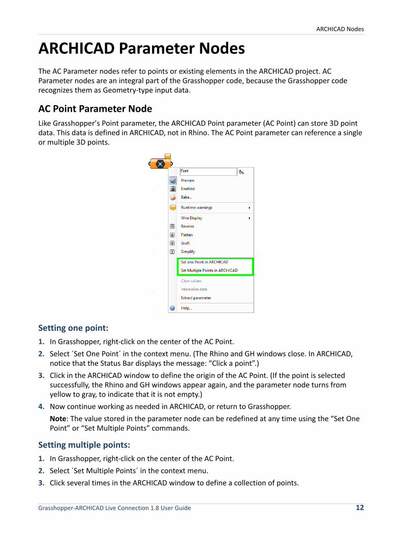
Like Grasshopper’s Point parameter, the ARCHICAD Point parameter (AC Point) can store 3D point data. This data is defined in ARCHICAD, not in Rhino. The AC Point parameter can reference a single or multiple 3D points.
Setting one point:
1. In Grasshopper, right-click on the center of the AC Point.
2. Select ´Set One Point´ in the context menu. (The Rhino and GH windows close. In ARCHICAD, notice that the Status Bar displays the message: “Click a point”.)
3. Click in the ARCHICAD window to define the origin of the AC Point. (If the point is selected successfully, the Rhino and GH windows appear again, and the parameter node turns from yellow to gray, to indicate that it is not empty.)
4. Now continue working as needed in ARCHICAD, or return to Grasshopper.
Note: The value stored in the parameter node can be redefined at any time using the “Set One Point” or “Set Multiple Points” commands.
Setting multiple points:
1. In Grasshopper, right-click on the center of the AC Point.
2. Select ´Set Multiple Points´ in the context menu.
3. Click several times in the ARCHICAD window to define a collection of points.
Grasshopper-ARCHICAD Live Connection 1.8 User Guide 12

ARCHICAD Nodes
4. Press ESCAPE on the keyboard to exit input mode.
Note: The AC Point component converts a point defined in ARCHICAD into a Grasshopper Point parameter. Thus, the AC Point parameter node can be assigned to any GH component that requires a GH Point-type input.
To define the origin of an AC Point, you can also click on any hotspot of a placed ARCHICAD element. In this case, the AC Point will remain associated to its parent element in ARCHICAD.
For example:
1. In Grasshopper, place two AC Point parameter nodes.
2. To define their origins, go to ARCHICAD and click the endpoints of an already placed Beam element.
3. In ARCHICAD, move the Beam to a new position.
4. Click the ‘Send Changes’ button on the Grasshopper Connection Palette: the coordinates stored in the AC Point parameters are modified to match the Beam’s new position.
2D Curve Parameter Node
2D Curve Parameter can reference one or more 2D elements drawn in ARCHICAD with the Line, Polyline or Circle Tool.
Note: You can use the 2D Curve parameter to reference any Polyline or Circle element drawn in a 2D ARCHICAD Viewpoint. However, in Grasshopper, the new planar shape will always be drawn in the XY plane.
Referencing a polyline in ARCHICAD:
1. Draw a polyline in ARCHICAD with the Polyline Tool.
2. In Grasshopper, place an AC 2D Curve parameter and right-click on its center.
3. Select ‘Set One 2D Curve’ from the context menu. (The Rhino and GH windows close. In ARCHICAD, notice that the Status Bar displays the message: “Click an element”.)
Note: If any ARCHICAD elements are selected at the time you issue the ‘Set One 2D Curve’ command, and if the set of selected elements includes one element drawn with the Polyline/Line/Circle Tool, then the parameter is automatically defined according to the selected element, and no further element selection is needed. If the selection does not include a Polyline/Line/Circle element, or if there are multiple selected Polylines/Lines/Circles, then the program will deselect the elements, and prompt you to select elements in ARCHICAD.
4. Click on the previously drawn polyline in the ARCHICAD window. The 2D Curve parameter is now referencing the selected ARCHICAD element.
Grasshopper-ARCHICAD Live Connection 1.8 User Guide 13
ARCHICAD Nodes
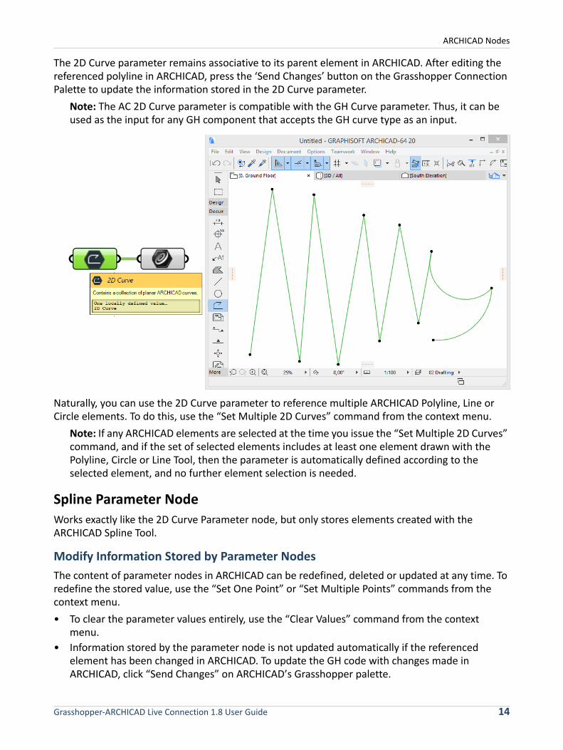
The 2D Curve parameter remains associative to its parent element in ARCHICAD. After editing the referenced polyline in ARCHICAD, press the ‘Send Changes’ button on the Grasshopper Connection Palette to update the information stored in the 2D Curve parameter.
Note: The AC 2D Curve parameter is compatible with the GH Curve parameter. Thus, it can be used as the input for any GH component that accepts the GH curve type as an input.
Naturally, you can use the 2D Curve parameter to reference multiple ARCHICAD Polyline, Line or Circle elements. To do this, use the “Set Multiple 2D Curves” command from the context menu.
Note: If any ARCHICAD elements are selected at the time you issue the “Set Multiple 2D Curves” command, and if the set of selected elements includes at least one element drawn with the Polyline, Circle or Line Tool, then the parameter is automatically defined according to the selected element, and no further element selection is needed.
Spline Parameter Node
Works exactly like the 2D Curve Parameter node, but only stores elements created with the ARCHICAD Spline Tool.
Modify Information Stored by Parameter Nodes
The content of parameter nodes in ARCHICAD can be redefined, deleted or updated at any time. To redefine the stored value, use the “Set One Point” or “Set Multiple Points” commands from the context menu.
• To clear the parameter values entirely, use the “Clear Values” command from the context menu.
• Information stored by the parameter node is not updated automatically if the referenced element has been changed in ARCHICAD. To update the GH code with changes made in ARCHICAD, click “Send Changes” on ARCHICAD’s Grasshopper palette.
Grasshopper-ARCHICAD Live Connection 1.8 User Guide 14
ARCHICAD Nodes
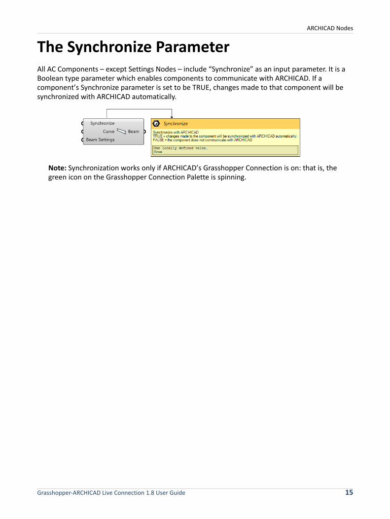
The Synchronize ParameterAll AC Components – except Settings Nodes – include “Synchronize” as an input parameter. It is a Boolean type parameter which enables components to communicate with ARCHICAD. If a component’s Synchronize parameter is set to be TRUE, changes made to that component will be synchronized with ARCHICAD automatically.
Note: Synchronization works only if ARCHICAD’s Grasshopper Connection is on: that is, the green icon on the Grasshopper Connection Palette is spinning.
Grasshopper-ARCHICAD Live Connection 1.8 User Guide 15
ARCHICAD Nodes
The Settings Parameter and Settings NodesEach Document and Design Component (which generate new elements in ARCHICAD) includes a Settings input parameter. Use the Settings component to define the parameters and attributes of the new ARCHICAD element. You can attach two types of nodes to the Settings input parameter:
• If you will control all of the new element’s parameters from Grasshopper, attach the Favorite Input Node to the Settings input parameter (see Input Node for more information).
• If you want to control only certain of the new element’s parameters from Grasshopper, then attach the Settings node (Wall Settings, Slab Settings, etc.) that corresponds to the type of generated element to the Settings input parameter.
It is not necessary to use the Settings input parameter. In this case, the newly generated element will use the current Default Settings of its corresponding tool in ARCHICAD.
Each ARCHICAD element type has a Settings Node. Each input parameter on the left of the Settings Node corresponds to a parameter in the ARCHICAD tool settings dialog box (although there are fewer parameters in the Settings Node). It is not necessary to define any of the Settings Node input parameters in Grasshopper. If any parameter is left empty in Grasshopper, the generated ARCHICAD element will use the default value of the corresponding default Tool Settings dialog box.
The right side of the Settings node has a single output parameter, which transfers the input data to the Design or Document component.
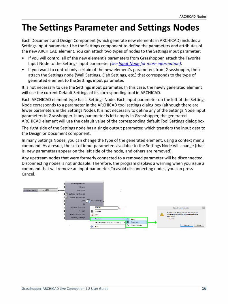
In many Settings Nodes, you can change the type of the generated element, using a context menu command. As a result, the set of input parameters available to the Settings Node will change (that is, new parameters appear on the left side of the node, and others are removed).
Any upstream nodes that were formerly connected to a removed parameter will be disconnected. Disconnecting nodes is not undoable. Therefore, the program displays a warning when you issue a command that will remove an input parameter. To avoid disconnecting nodes, you can press Cancel.
Grasshopper-ARCHICAD Live Connection 1.8 User Guide 16
ARCHICAD Nodes
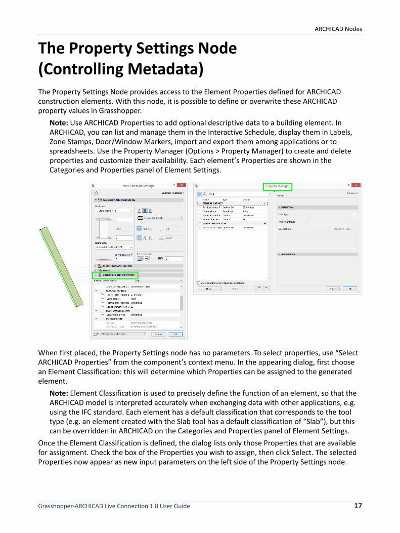
The Property Settings Node (Controlling Metadata)The Property Settings Node provides access to the Element Properties defined for ARCHICAD construction elements. With this node, it is possible to define or overwrite these ARCHICAD property values in Grasshopper.
Note: Use ARCHICAD Properties to add optional descriptive data to a building element. In ARCHICAD, you can list and manage them in the Interactive Schedule, display them in Labels, Zone Stamps, Door/Window Markers, import and export them among applications or to spreadsheets. Use the Property Manager (Options > Property Manager) to create and delete properties and customize their availability. Each element’s Properties are shown in the Categories and Properties panel of Element Settings.
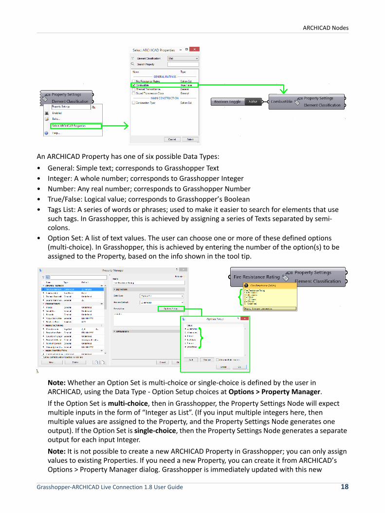
When first placed, the Property Settings node has no parameters. To select properties, use “Select ARCHICAD Properties” from the component’s context menu. In the appearing dialog, first choose an Element Classification: this will determine which Properties can be assigned to the generated element.
Note: Element Classification is used to precisely define the function of an element, so that the ARCHICAD model is interpreted accurately when exchanging data with other applications, e.g. using the IFC standard. Each element has a default classification that corresponds to the tool type (e.g. an element created with the Slab tool has a default classification of “Slab”), but this can be overridden in ARCHICAD on the Categories and Properties panel of Element Settings.
Once the Element Classification is defined, the dialog lists only those Properties that are available for assignment. Check the box of the Properties you wish to assign, then click Select. The selected Properties now appear as new input parameters on the left side of the Property Settings node.
Grasshopper-ARCHICAD Live Connection 1.8 User Guide 17
ARCHICAD Nodes
An ARCHICAD Property has one of six possible Data Types:
• General: Simple text; corresponds to Grasshopper Text
• Integer: A whole number; corresponds to Grasshopper Integer
• Number: Any real number; corresponds to Grasshopper Number
• True/False: Logical value; corresponds to Grasshopper’s Boolean
• Tags List: A series of words or phrases; used to make it easier to search for elements that use such tags. In Grasshopper, this is achieved by assigning a series of Texts separated by semi-colons.
• Option Set: A list of text values. The user can choose one or more of these defined options (multi-choice). In Grasshopper, this is achieved by entering the number of the option(s) to be assigned to the Property, based on the info shown in the tool tip.
Note: Whether an Option Set is multi-choice or single-choice is defined by the user in ARCHICAD, using the Data Type - Option Setup choices at Options > Property Manager.
If the Option Set is multi-choice, then in Grasshopper, the Property Settings Node will expect multiple inputs in the form of “Integer as List”. (If you input multiple integers here, then multiple values are assigned to the Property, and the Property Settings Node generates one output). If the Option Set is single-choice, then the Property Settings Node generates a separate output for each input Integer.
Note: It is not possible to create a new ARCHICAD Property in Grasshopper; you can only assign values to existing Properties. If you need a new Property, you can create it from ARCHICAD’s Options > Property Manager dialog. Grasshopper is immediately updated with this new
Grasshopper-ARCHICAD Live Connection 1.8 User Guide 18
ARCHICAD Nodes
information: the next time you open the Select ARCHICAD Property dialog, the newly created Property will be listed.
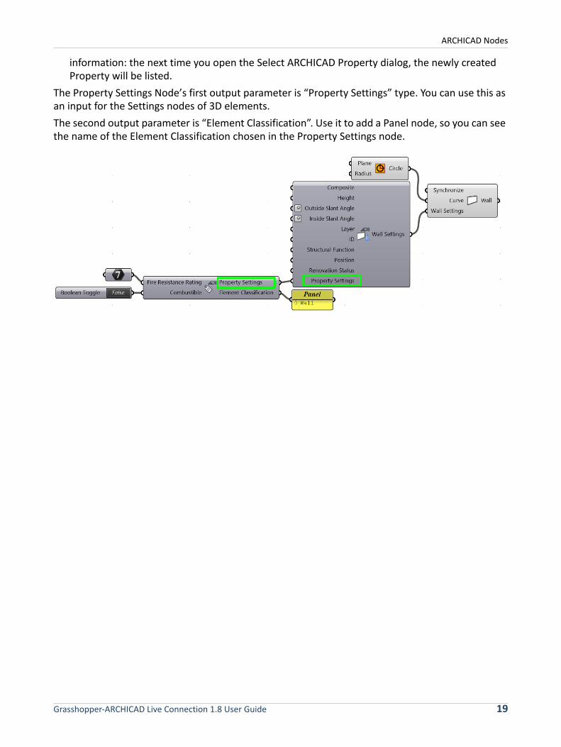
The Property Settings Node’s first output parameter is “Property Settings” type. You can use this as an input for the Settings nodes of 3D elements.
The second output parameter is “Element Classification”. Use it to add a Panel node, so you can see the name of the Element Classification chosen in the Property Settings node.
Grasshopper-ARCHICAD Live Connection 1.8 User Guide 19
ARCHICAD Nodes
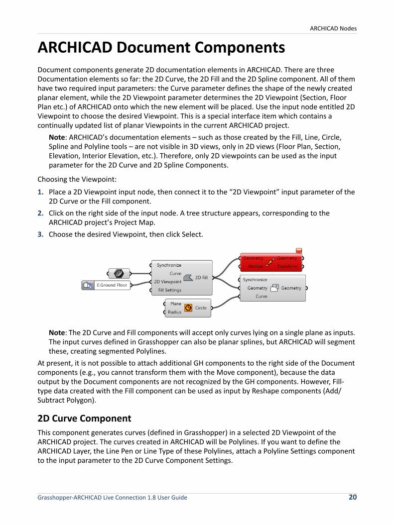
ARCHICAD Document ComponentsDocument components generate 2D documentation elements in ARCHICAD. There are three Documentation elements so far: the 2D Curve, the 2D Fill and the 2D Spline component. All of them have two required input parameters: the Curve parameter defines the shape of the newly created planar element, while the 2D Viewpoint parameter determines the 2D Viewpoint (Section, Floor Plan etc.) of ARCHICAD onto which the new element will be placed. Use the input node entitled 2D Viewpoint to choose the desired Viewpoint. This is a special interface item which contains a continually updated list of planar Viewpoints in the current ARCHICAD project.
Note: ARCHICAD’s documentation elements – such as those created by the Fill, Line, Circle, Spline and Polyline tools – are not visible in 3D views, only in 2D views (Floor Plan, Section, Elevation, Interior Elevation, etc.). Therefore, only 2D viewpoints can be used as the input parameter for the 2D Curve and 2D Spline Components.
Choosing the Viewpoint:
1. Place a 2D Viewpoint input node, then connect it to the “2D Viewpoint” input parameter of the 2D Curve or the Fill component.
2. Click on the right side of the input node. A tree structure appears, corresponding to the ARCHICAD project’s Project Map.
3. Choose the desired Viewpoint, then click Select.
Note: The 2D Curve and Fill components will accept only curves lying on a single plane as inputs. The input curves defined in Grasshopper can also be planar splines, but ARCHICAD will segment these, creating segmented Polylines.
At present, it is not possible to attach additional GH components to the right side of the Document components (e.g., you cannot transform them with the Move component), because the data output by the Document components are not recognized by the GH components. However, Fill-type data created with the Fill component can be used as input by Reshape components (Add/Subtract Polygon).
2D Curve Component
This component generates curves (defined in Grasshopper) in a selected 2D Viewpoint of the ARCHICAD project. The curves created in ARCHICAD will be Polylines. If you want to define the ARCHICAD Layer, the Line Pen or Line Type of these Polylines, attach a Polyline Settings component to the input parameter to the 2D Curve Component Settings.
Grasshopper-ARCHICAD Live Connection 1.8 User Guide 20
ARCHICAD Nodes
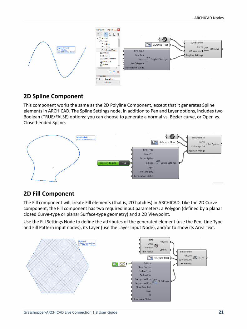
2D Spline Component
This component works the same as the 2D Polyline Component, except that it generates Spline elements in ARCHICAD. The Spline Settings node, in addition to Pen and Layer options, includes two Boolean (TRUE/FALSE) options: you can choose to generate a normal vs. Bézier curve, or Open vs. Closed-ended Spline.
2D Fill Component
The Fill component will create Fill elements (that is, 2D hatches) in ARCHICAD. Like the 2D Curve component, the Fill component has two required input parameters: a Polygon (defined by a planar closed Curve-type or planar Surface-type geometry) and a 2D Viewpoint.
Use the Fill Settings Node to define the attributes of the generated element (use the Pen, Line Type and Fill Pattern input nodes), its Layer (use the Layer Input Node), and/or to show its Area Text.
Grasshopper-ARCHICAD Live Connection 1.8 User Guide 21
ARCHICAD Nodes
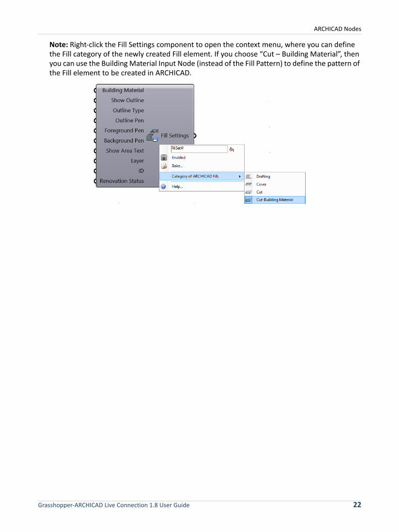
Note: Right-click the Fill Settings component to open the context menu, where you can define the Fill category of the newly created Fill element. If you choose “Cut – Building Material”, then you can use the Building Material Input Node (instead of the Fill Pattern) to define the pattern of the Fill element to be created in ARCHICAD.
Grasshopper-ARCHICAD Live Connection 1.8 User Guide 22
ARCHICAD Nodes
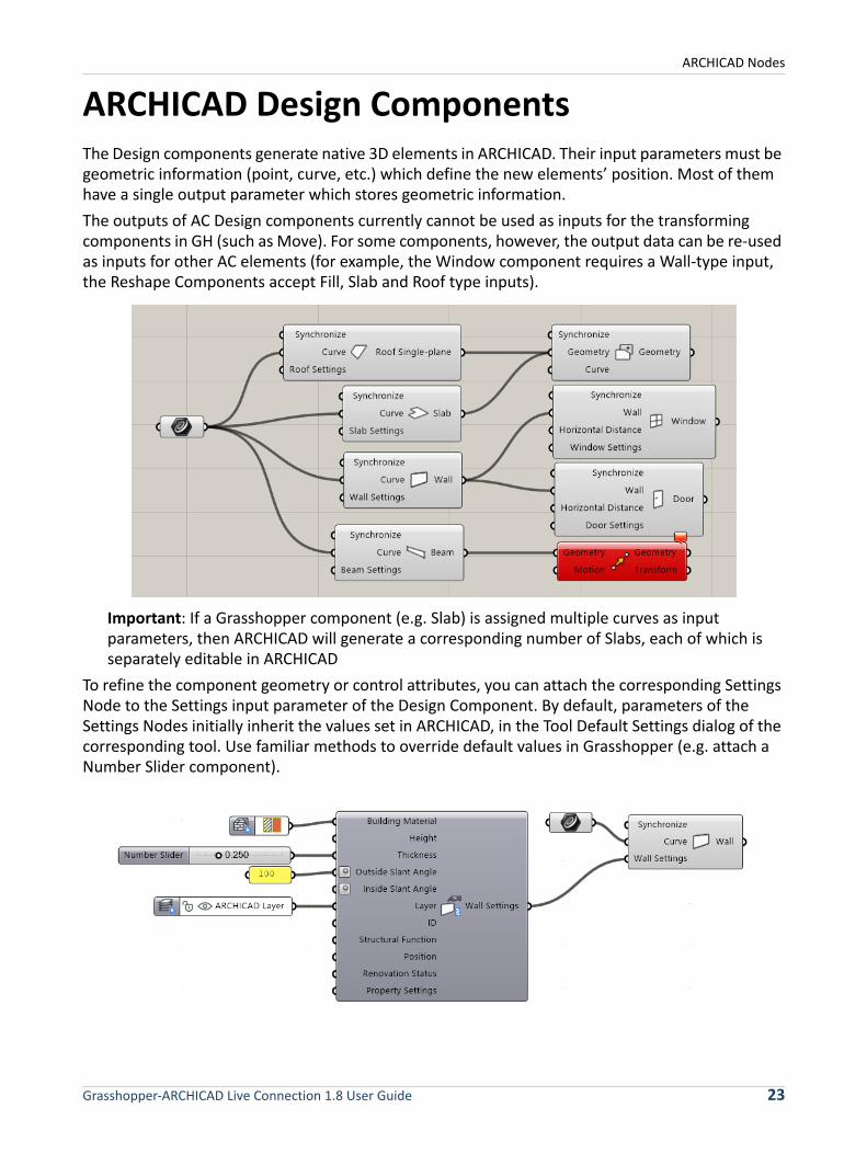
ARCHICAD Design ComponentsThe Design components generate native 3D elements in ARCHICAD. Their input parameters must be geometric information (point, curve, etc.) which define the new elements’ position. Most of them have a single output parameter which stores geometric information.
The outputs of AC Design components currently cannot be used as inputs for the transforming components in GH (such as Move). For some components, however, the output data can be re-used as inputs for other AC elements (for example, the Window component requires a Wall-type input, the Reshape Components accept Fill, Slab and Roof type inputs).
Important: If a Grasshopper component (e.g. Slab) is assigned multiple curves as input parameters, then ARCHICAD will generate a corresponding number of Slabs, each of which is separately editable in ARCHICAD
To refine the component geometry or control attributes, you can attach the corresponding Settings Node to the Settings input parameter of the Design Component. By default, parameters of the Settings Nodes initially inherit the values set in ARCHICAD, in the Tool Default Settings dialog of the corresponding tool. Use familiar methods to override default values in Grasshopper (e.g. attach a Number Slider component).
Grasshopper-ARCHICAD Live Connection 1.8 User Guide 23
ARCHICAD Nodes
Note: Many ARCHICAD-based parameters of design elements are not yet available for Grasshopper’s AC components. The value of these parameters, at the time the component is first generated, will equal the current default value set for the corresponding tool in ARCHICAD.
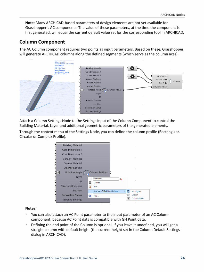
Column Component
The AC Column component requires two points as input parameters. Based on these, Grasshopper will generate ARCHICAD columns along the defined segments (which serve as the column axes).
Attach a Column Settings Node to the Settings Input of the Column Component to control the Building Material, Layer and additional geometric parameters of the generated elements.
Through the context menu of the Settings Node, you can define the column profile (Rectangular, Circular or Complex Profile).
Notes:
◦ You can also attach an AC Point parameter to the input parameter of an AC Column component, because AC Point data is compatible with GH Point data.
◦ Defining the end point of the Column is optional. If you leave it undefined, you will get a straight column with default height (the current height set in the Column Default Settings dialog in ARCHICAD).
Grasshopper-ARCHICAD Live Connection 1.8 User Guide 24
ARCHICAD Nodes
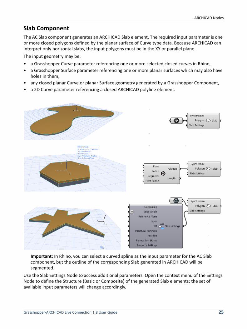
Slab Component
The AC Slab component generates an ARCHICAD Slab element. The required input parameter is one or more closed polygons defined by the planar surface of Curve type data. Because ARCHICAD can interpret only horizontal slabs, the input polygons must be in the XY or parallel plane.
The input geometry may be:
• a Grasshopper Curve parameter referencing one or more selected closed curves in Rhino,
• a Grasshopper Surface parameter referencing one or more planar surfaces which may also have holes in them,
• any closed planar Curve or planar Surface geometry generated by a Grasshopper Component,
• a 2D Curve parameter referencing a closed ARCHICAD polyline element.
Important: In Rhino, you can select a curved spline as the input parameter for the AC Slab component, but the outline of the corresponding Slab generated in ARCHICAD will be segmented.
Use the Slab Settings Node to access additional parameters. Open the context menu of the Settings Node to define the Structure (Basic or Composite) of the generated Slab elements; the set of available input parameters will change accordingly.
Grasshopper-ARCHICAD Live Connection 1.8 User Guide 25
ARCHICAD Nodes
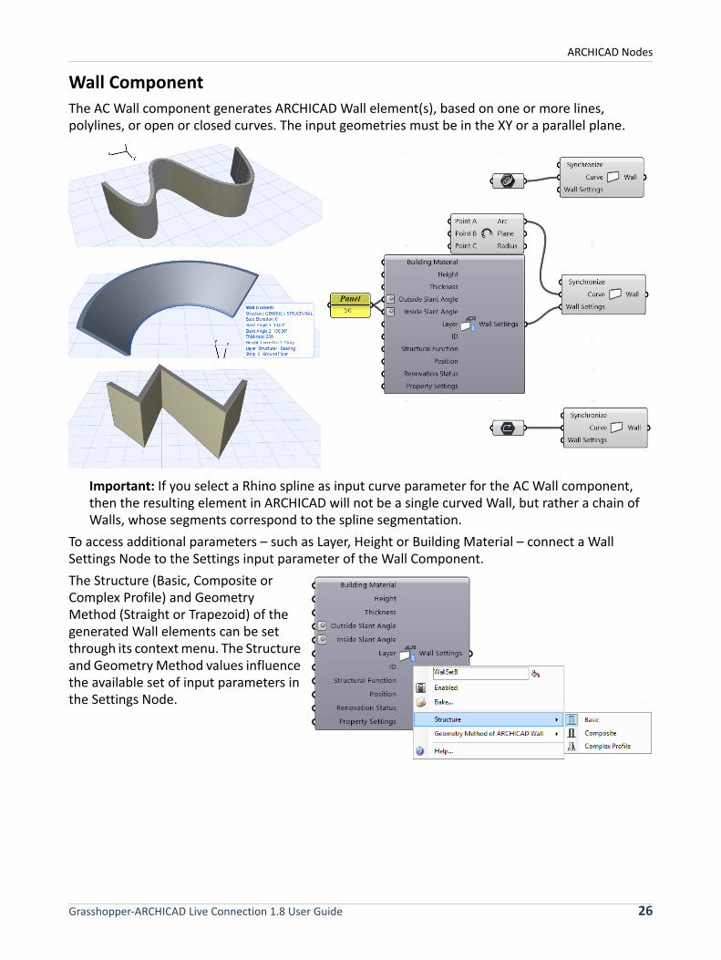
Wall Component
The AC Wall component generates ARCHICAD Wall element(s), based on one or more lines, polylines, or open or closed curves. The input geometries must be in the XY or a parallel plane.
Important: If you select a Rhino spline as input curve parameter for the AC Wall component, then the resulting element in ARCHICAD will not be a single curved Wall, but rather a chain of Walls, whose segments correspond to the spline segmentation.
To access additional parameters – such as Layer, Height or Building Material – connect a Wall Settings Node to the Settings input parameter of the Wall Component.
The Structure (Basic, Composite or Complex Profile) and Geometry Method (Straight or Trapezoid) of the generated Wall elements can be set through its context menu. The Structure and Geometry Method values influence the available set of input parameters in the Settings Node.
Grasshopper-ARCHICAD Live Connection 1.8 User Guide 26
ARCHICAD Nodes
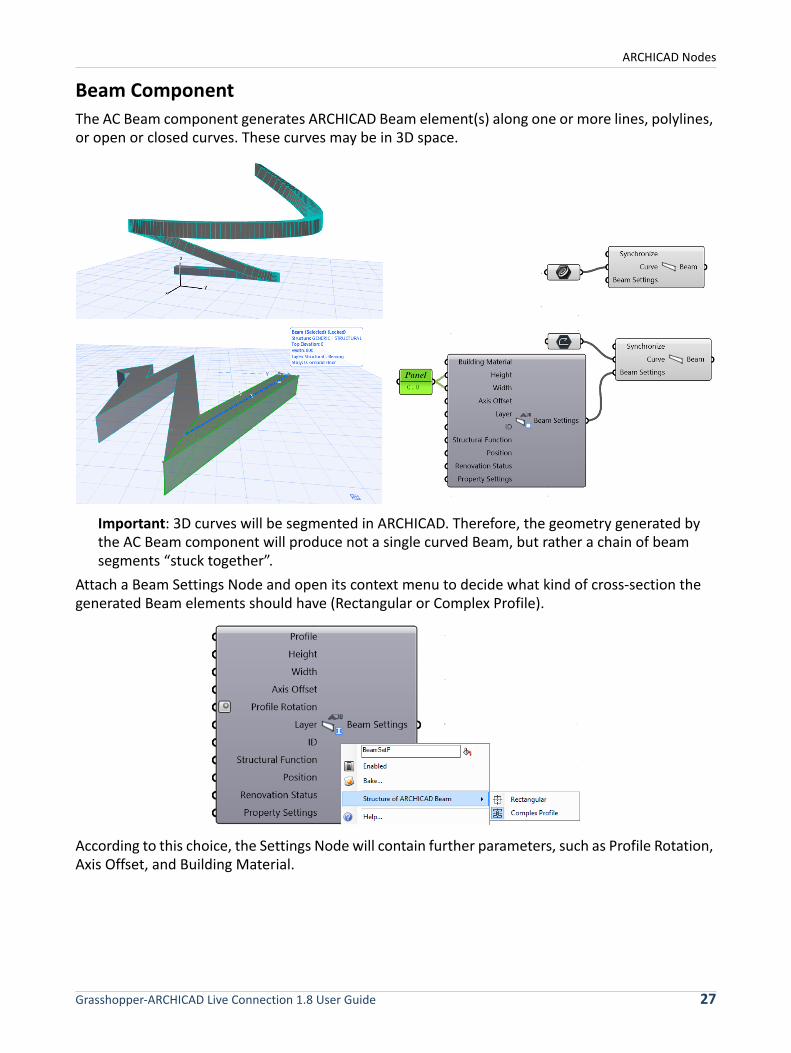
Beam Component
The AC Beam component generates ARCHICAD Beam element(s) along one or more lines, polylines, or open or closed curves. These curves may be in 3D space.
Important: 3D curves will be segmented in ARCHICAD. Therefore, the geometry generated by the AC Beam component will produce not a single curved Beam, but rather a chain of beam segments “stuck together”.
Attach a Beam Settings Node and open its context menu to decide what kind of cross-section the generated Beam elements should have (Rectangular or Complex Profile).
According to this choice, the Settings Node will contain further parameters, such as Profile Rotation, Axis Offset, and Building Material.
Grasshopper-ARCHICAD Live Connection 1.8 User Guide 27
ARCHICAD Nodes
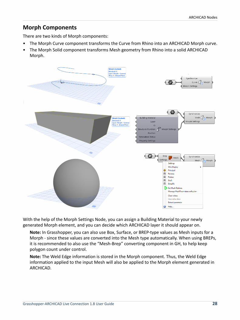
Morph Components
There are two kinds of Morph components:
• The Morph Curve component transforms the Curve from Rhino into an ARCHICAD Morph curve.
• The Morph Solid component transforms Mesh geometry from Rhino into a solid ARCHICAD Morph.
With the help of the Morph Settings Node, you can assign a Building Material to your newly generated Morph element, and you can decide which ARCHICAD layer it should appear on.
Note: In Grasshopper, you can also use Box, Surface, or BREP-type values as Mesh inputs for a Morph - since these values are converted into the Mesh type automatically. When using BREPs, it is recommended to also use the “Mesh-Brep” converting component in GH, to help keep polygon count under control.
Note: The Weld Edge information is stored in the Morph component. Thus, the Weld Edge information applied to the input Mesh will also be applied to the Morph element generated in ARCHICAD.
Grasshopper-ARCHICAD Live Connection 1.8 User Guide 28
ARCHICAD Nodes
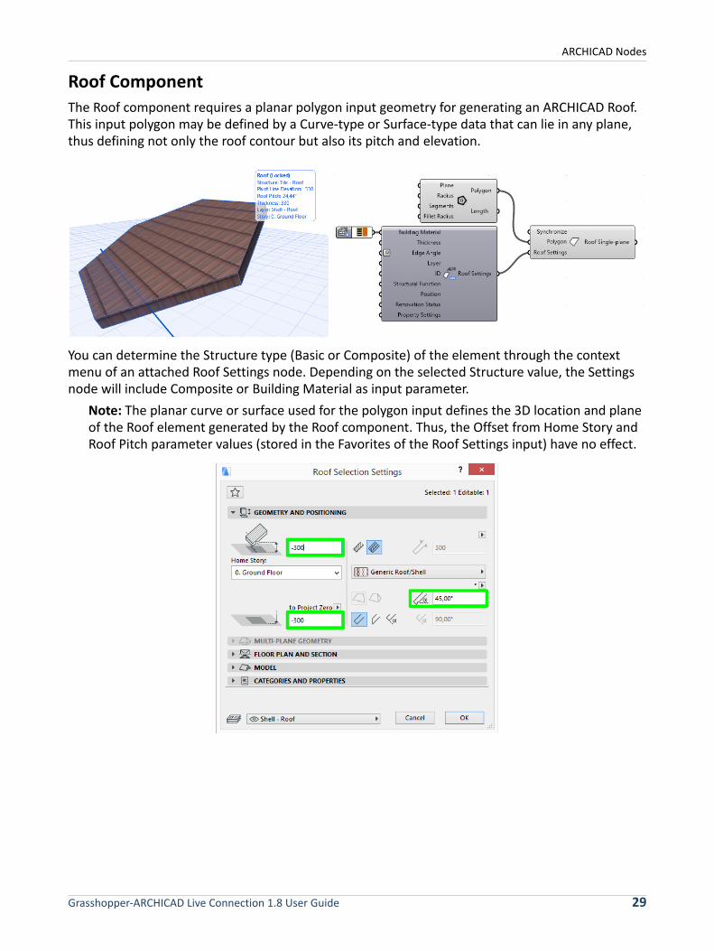
Roof Component
The Roof component requires a planar polygon input geometry for generating an ARCHICAD Roof. This input polygon may be defined by a Curve-type or Surface-type data that can lie in any plane, thus defining not only the roof contour but also its pitch and elevation.
You can determine the Structure type (Basic or Composite) of the element through the context menu of an attached Roof Settings node. Depending on the selected Structure value, the Settings node will include Composite or Building Material as input parameter.
Note: The planar curve or surface used for the polygon input defines the 3D location and plane of the Roof element generated by the Roof component. Thus, the Offset from Home Story and Roof Pitch parameter values (stored in the Favorites of the Roof Settings input) have no effect.
Grasshopper-ARCHICAD Live Connection 1.8 User Guide 29
ARCHICAD Nodes
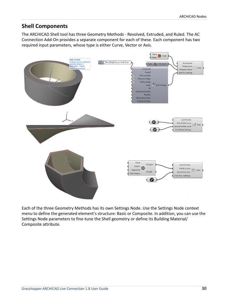
Shell Components
The ARCHICAD Shell tool has three Geometry Methods - Revolved, Extruded, and Ruled. The AC Connection Add-On provides a separate component for each of these. Each component has two required input parameters, whose type is either Curve, Vector or Axis.
Each of the three Geometry Methods has its own Settings Node. Use the Settings Node context menu to define the generated element’s structure: Basic or Composite. In addition, you can use the Settings Node parameters to fine-tune the Shell geometry or define its Building Material/Composite attribute.
Grasshopper-ARCHICAD Live Connection 1.8 User Guide 30
ARCHICAD Nodes
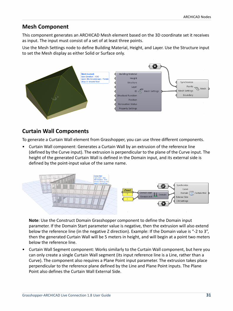
Mesh Component
This component generates an ARCHICAD Mesh element based on the 3D coordinate set it receives as input. The input must consist of a set of at least three points.
Use the Mesh Settings node to define Building Material, Height, and Layer. Use the Structure input to set the Mesh display as either Solid or Surface only.
Curtain Wall Components
To generate a Curtain Wall element from Grasshopper, you can use three different components.
• Curtain Wall component: Generates a Curtain Wall by an extrusion of the reference line (defined by the Curve input). The extrusion is perpendicular to the plane of the Curve input. The height of the generated Curtain Wall is defined in the Domain input, and its external side is defined by the point-input value of the same name.
Note: Use the Construct Domain Grasshopper component to define the Domain input parameter. If the Domain Start parameter value is negative, then the extrusion will also extend below the reference line (in the negative Z direction). Example: If the Domain value is “-2 to 3”, then the generated Curtain Wall will be 5 meters in height, and will begin at a point two meters below the reference line.
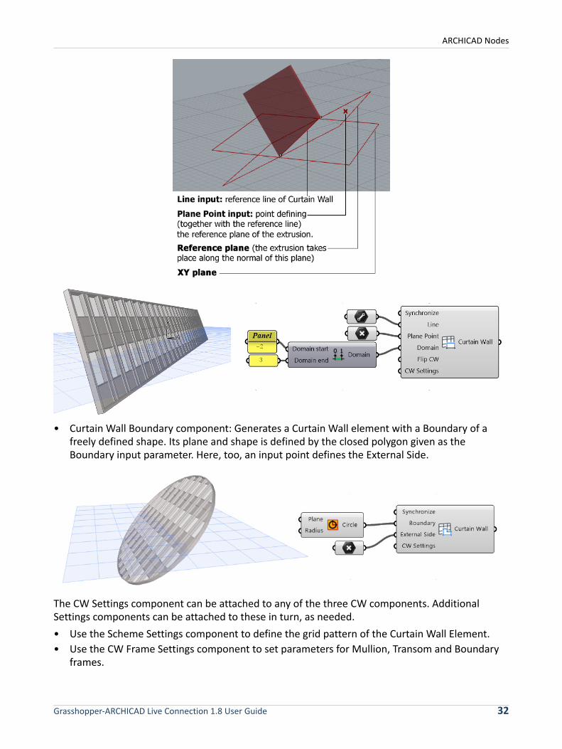
• Curtain Wall Segment component: Works similarly to the Curtain Wall component, but here you can only create a single Curtain Wall segment (its input reference line is a Line, rather than a Curve). The component also requires a Plane Point input parameter. The extrusion takes place perpendicular to the reference plane defined by the Line and Plane Point inputs. The Plane Point also defines the Curtain Wall External Side.
Grasshopper-ARCHICAD Live Connection 1.8 User Guide 31
ARCHICAD Nodes
• Curtain Wall Boundary component: Generates a Curtain Wall element with a Boundary of a freely defined shape. Its plane and shape is defined by the closed polygon given as the Boundary input parameter. Here, too, an input point defines the External Side.
The CW Settings component can be attached to any of the three CW components. Additional Settings components can be attached to these in turn, as needed.
• Use the Scheme Settings component to define the grid pattern of the Curtain Wall Element.
• Use the CW Frame Settings component to set parameters for Mullion, Transom and Boundary frames.
Grasshopper-ARCHICAD Live Connection 1.8 User Guide 32
ARCHICAD Nodes
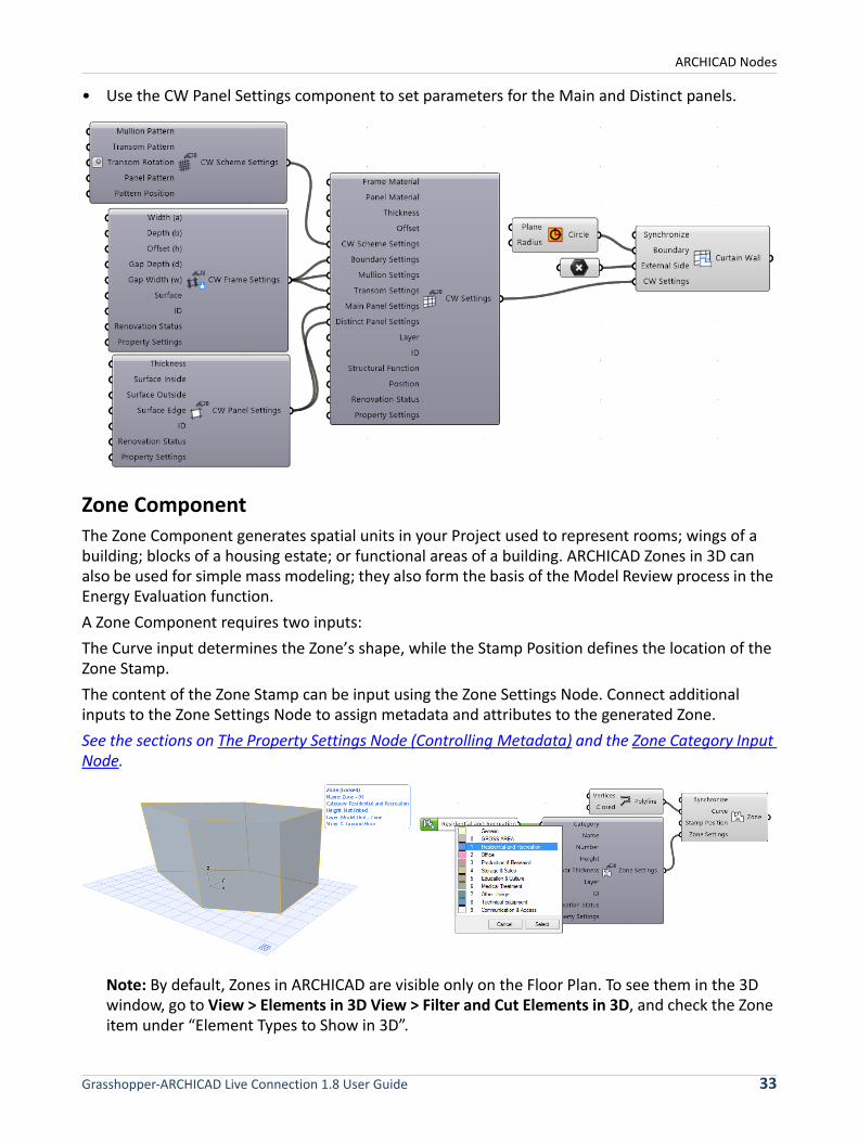
• Use the CW Panel Settings component to set parameters for the Main and Distinct panels.
Zone Component
The Zone Component generates spatial units in your Project used to represent rooms; wings of a building; blocks of a housing estate; or functional areas of a building. ARCHICAD Zones in 3D can also be used for simple mass modeling; they also form the basis of the Model Review process in the Energy Evaluation function.
A Zone Component requires two inputs:
The Curve input determines the Zone’s shape, while the Stamp Position defines the location of the Zone Stamp.
The content of the Zone Stamp can be input using the Zone Settings Node. Connect additional inputs to the Zone Settings Node to assign metadata and attributes to the generated Zone.
See the sections on The Property Settings Node (Controlling Metadata) and the Zone Category Input Node.
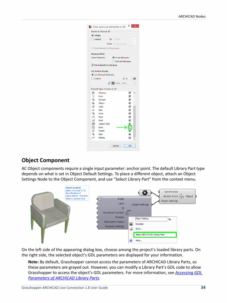
Note: By default, Zones in ARCHICAD are visible only on the Floor Plan. To see them in the 3D window, go to View > Elements in 3D View > Filter and Cut Elements in 3D, and check the Zone item under “Element Types to Show in 3D”.
Grasshopper-ARCHICAD Live Connection 1.8 User Guide 33
ARCHICAD Nodes
Object Component
AC Object components require a single input parameter: anchor point. The default Library Part type depends on what is set in Object Default Settings. To place a different object, attach an Object Settings Node to the Object Component, and use “Select Library Part” from the context menu.
On the left side of the appearing dialog box, choose among the project’s loaded library parts. On the right side, the selected object’s GDL parameters are displayed for your information.
Note: By default, Grasshopper cannot access the parameters of ARCHICAD Library Parts, so these parameters are grayed out. However, you can modify a Library Part’s GDL code to allow Grasshopper to access the object’s GDL parameters. For more information, see Accessing GDL Parameters of ARCHICAD Library Parts.
Grasshopper-ARCHICAD Live Connection 1.8 User Guide 34
ARCHICAD Nodes
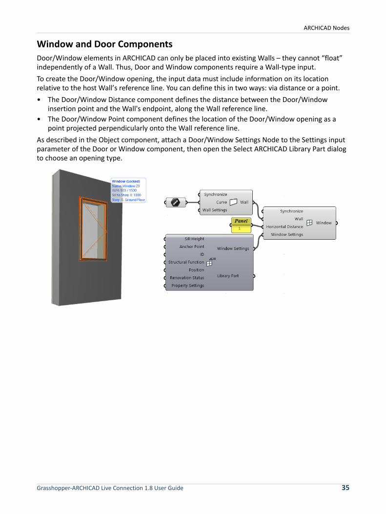
Window and Door Components
Door/Window elements in ARCHICAD can only be placed into existing Walls – they cannot “float” independently of a Wall. Thus, Door and Window components require a Wall-type input.
To create the Door/Window opening, the input data must include information on its location relative to the host Wall’s reference line. You can define this in two ways: via distance or a point.
• The Door/Window Distance component defines the distance between the Door/Window insertion point and the Wall's endpoint, along the Wall reference line.
• The Door/Window Point component defines the location of the Door/Window opening as a point projected perpendicularly onto the Wall reference line.
As described in the Object component, attach a Door/Window Settings Node to the Settings input parameter of the Door or Window component, then open the Select ARCHICAD Library Part dialog to choose an opening type.
Grasshopper-ARCHICAD Live Connection 1.8 User Guide 35
ARCHICAD Nodes
ARCHICAD Reshape Components
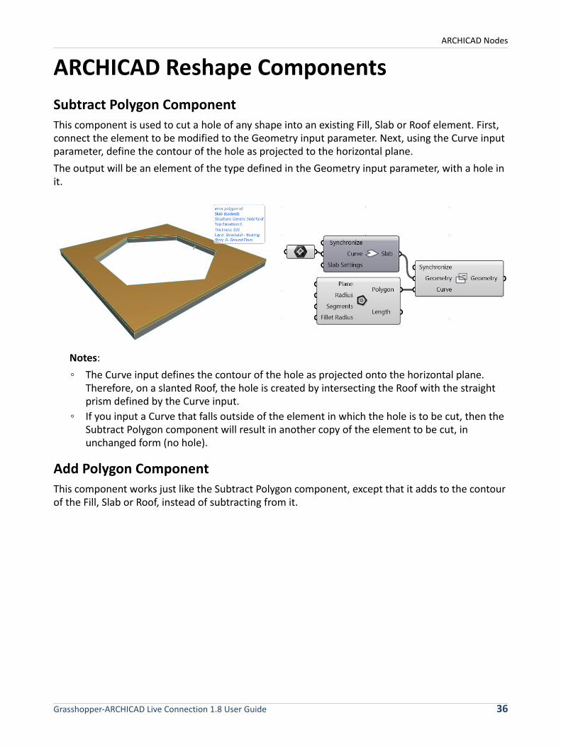
Subtract Polygon Component
This component is used to cut a hole of any shape into an existing Fill, Slab or Roof element. First, connect the element to be modified to the Geometry input parameter. Next, using the Curve input parameter, define the contour of the hole as projected to the horizontal plane.
The output will be an element of the type defined in the Geometry input parameter, with a hole in it.
Notes:
◦ The Curve input defines the contour of the hole as projected onto the horizontal plane. Therefore, on a slanted Roof, the hole is created by intersecting the Roof with the straight prism defined by the Curve input.
◦ If you input a Curve that falls outside of the element in which the hole is to be cut, then the Subtract Polygon component will result in another copy of the element to be cut, in unchanged form (no hole).
Add Polygon Component
This component works just like the Subtract Polygon component, except that it adds to the contour of the Fill, Slab or Roof, instead of subtracting from it.
Grasshopper-ARCHICAD Live Connection 1.8 User Guide 36
ARCHICAD Nodes
ARCHICAD Input NodesInput Nodes are special interface elements that reference certain data from the ARCHICAD project, making these data available to Grasshopper. The referenced data are continuously updated. Input Nodes can be attached to Settings Nodes to control attributes – such as Building Material, Composite, Pen etc. – or the destination Layer of the generated elements. An exception is the Favorite Input Node, which can be attached (instead of a Settings Node) to the main Design or Document component.
An Input Node is divided into two parts: click on its left side to select the Node itself; click on its right side to modify its stored data.
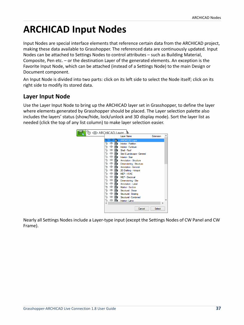
Layer Input Node
Use the Layer Input Node to bring up the ARCHICAD layer set in Grasshopper, to define the layer where elements generated by Grasshopper should be placed. The Layer selection palette also includes the layers’ status (show/hide, lock/unlock and 3D display mode). Sort the layer list as needed (click the top of any list column) to make layer selection easier.
Nearly all Settings Nodes include a Layer-type input (except the Settings Nodes of CW Panel and CW Frame).
Grasshopper-ARCHICAD Live Connection 1.8 User Guide 37
ARCHICAD Nodes
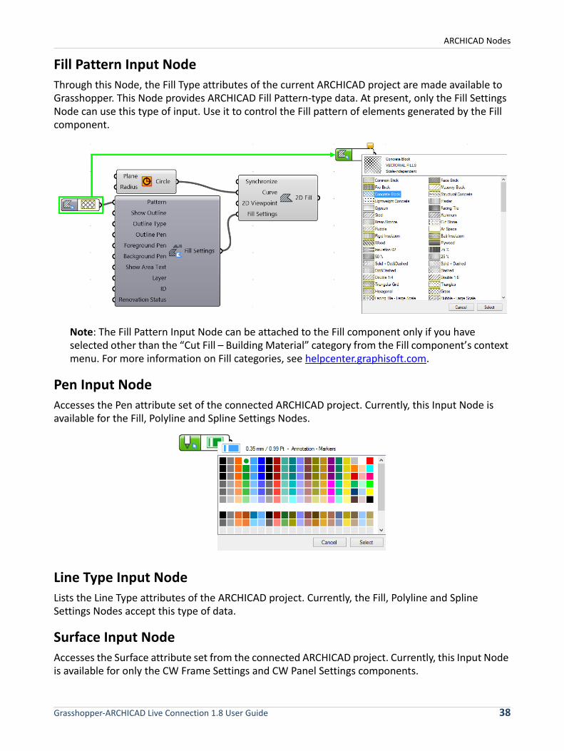
Fill Pattern Input Node
Through this Node, the Fill Type attributes of the current ARCHICAD project are made available to Grasshopper. This Node provides ARCHICAD Fill Pattern-type data. At present, only the Fill Settings Node can use this type of input. Use it to control the Fill pattern of elements generated by the Fill component.
Note: The Fill Pattern Input Node can be attached to the Fill component only if you have selected other than the “Cut Fill – Building Material” category from the Fill component’s context menu. For more information on Fill categories, see helpcenter.graphisoft.com.
Pen Input Node
Accesses the Pen attribute set of the connected ARCHICAD project. Currently, this Input Node is available for the Fill, Polyline and Spline Settings Nodes.
Line Type Input Node
Lists the Line Type attributes of the ARCHICAD project. Currently, the Fill, Polyline and Spline Settings Nodes accept this type of data.
Surface Input Node
Accesses the Surface attribute set from the connected ARCHICAD project. Currently, this Input Node is available for only the CW Frame Settings and CW Panel Settings components.
Grasshopper-ARCHICAD Live Connection 1.8 User Guide 38
ARCHICAD Nodes
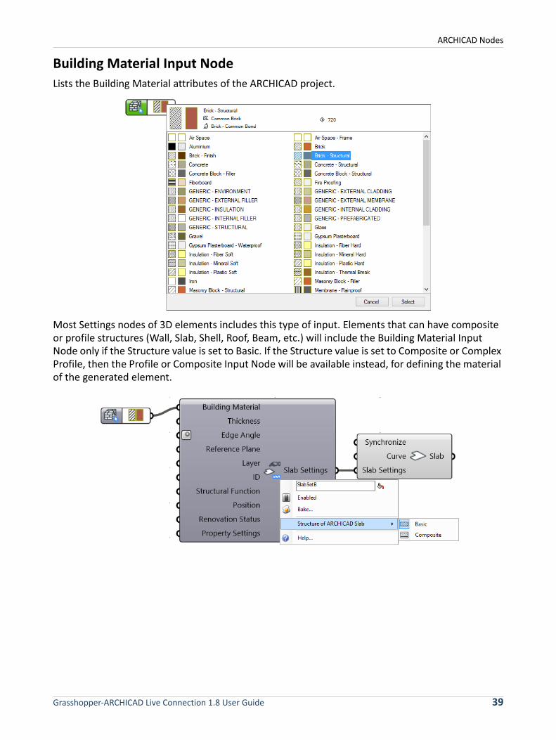
Building Material Input Node
Lists the Building Material attributes of the ARCHICAD project.
Most Settings nodes of 3D elements includes this type of input. Elements that can have composite or profile structures (Wall, Slab, Shell, Roof, Beam, etc.) will include the Building Material Input Node only if the Structure value is set to Basic. If the Structure value is set to Composite or Complex Profile, then the Profile or Composite Input Node will be available instead, for defining the material of the generated element.
Grasshopper-ARCHICAD Live Connection 1.8 User Guide 39
ARCHICAD Nodes
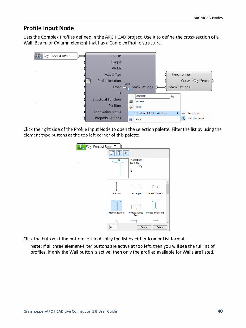
Profile Input Node
Lists the Complex Profiles defined in the ARCHICAD project. Use it to define the cross-section of a Wall, Beam, or Column element that has a Complex Profile structure.
Click the right side of the Profile Input Node to open the selection palette. Filter the list by using the element type buttons at the top left corner of this palette.
Click the button at the bottom left to display the list by either Icon or List format.
Note: If all three element-filter buttons are active at top left, then you will see the full list of profiles. If only the Wall button is active, then only the profiles available for Walls are listed.
Grasshopper-ARCHICAD Live Connection 1.8 User Guide 40

ARCHICAD Nodes
Composite Input Node
Lists the Composite attributes of the ARCHICAD project. This input parameter is available in the Settings nodes of Walls, Shells, Roofs and Slabs whose Structure is set (in their context menu) to Composite.
2D Viewpoint Input Node
Use the 2D Viewpoint Input Node to access the Viewpoints of the current ARCHICAD Project. By attaching this node to the Document components (2D Curve, 2D Fill, 2D Spline), you can control the 2D Viewpoint in which the 2D elements should be generated in the ARCHICAD project. Open the Node’s palette to access a tree structure corresponding to the ARCHICAD Project Map. Note that only the 2D views are available (Section/Elevation, Floor Plan, etc.); no 3D views are available.
Story Plane Input Node
Produces horizontal planes (parallel to the X-Y plane) based on the Story heights of the ARCHICAD project. Use these planes to define the reference input curves of the element-generating components: this way, the elements (e.g. Wall, Slab, Beam) will be generated in ARCHICAD at the correct elevations.
Grasshopper-ARCHICAD Live Connection 1.8 User Guide 41
ARCHICAD Nodes
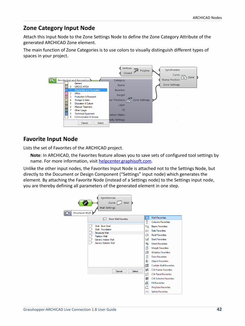
Zone Category Input Node
Attach this Input Node to the Zone Settings Node to define the Zone Category Attribute of the generated ARCHICAD Zone element.
The main function of Zone Categories is to use colors to visually distinguish different types of spaces in your project.
Favorite Input Node
Lists the set of Favorites of the ARCHICAD project.
Note: In ARCHICAD, the Favorites feature allows you to save sets of configured tool settings by name. For more information, visit helpcenter.graphisoft.com.
Unlike the other input nodes, the Favorites Input Node is attached not to the Settings Node, but directly to the Document or Design Component (“Settings” input node) which generates the element. By attaching the Favorite Node (instead of a Settings node) to the Settings input node, you are thereby defining all parameters of the generated element in one step.
Grasshopper-ARCHICAD Live Connection 1.8 User Guide 42
ARCHICAD Nodes
Note: The 3D position of elements generated by Grasshopper (such as the Offset from Home Story parameter in the Settings dialog) are defined in the mandatory input data of the Document and Design components, which generate the element. (For example, the elevation of a generated Slab is determined by the Curve input parameter of the Slab component.) The Settings parameters which define such mandatory input data are not affected by Favorite settings.
Grasshopper-ARCHICAD Live Connection 1.8 User Guide 43
Workflow Examples
Workflow Examples
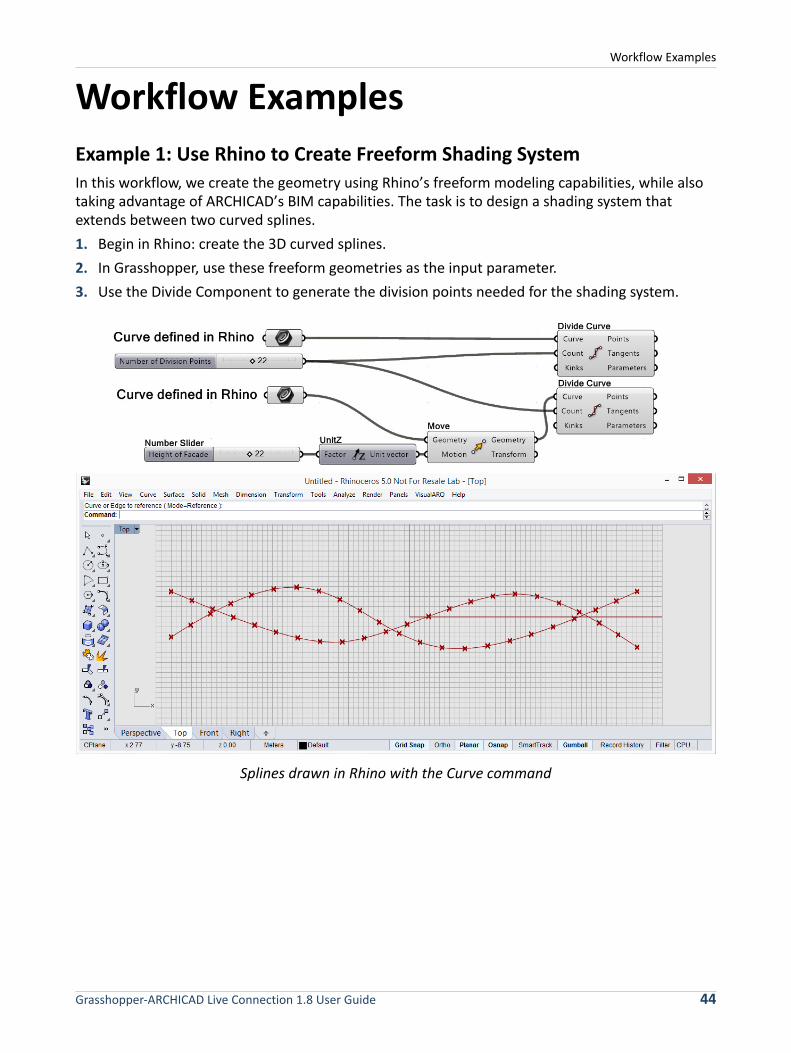
Example 1: Use Rhino to Create Freeform Shading System
In this workflow, we create the geometry using Rhino’s freeform modeling capabilities, while also taking advantage of ARCHICAD’s BIM capabilities. The task is to design a shading system that extends between two curved splines.
1. Begin in Rhino: create the 3D curved splines.
2. In Grasshopper, use these freeform geometries as the input parameter.
3. Use the Divide Component to generate the division points needed for the shading system.
Splines drawn in Rhino with the Curve command
Grasshopper-ARCHICAD Live Connection 1.8 User Guide 44

Workflow Examples
4. At each division point, place an AC Column component; at each spline, place an AC Beam component.
Generated BIM model in ARCHICAD based on 3D Rhino curves
5. You can fine-tune the geometry in Rhino by adjusting the original spline geometry (use the PointsOn command).
6. To define the Building Material attribute or Core Dimensions of the generated Columns, attach a Column Settings node to the corresponding input parameter of the Column Component.
Grasshopper-ARCHICAD Live Connection 1.8 User Guide 45
Workflow Examples
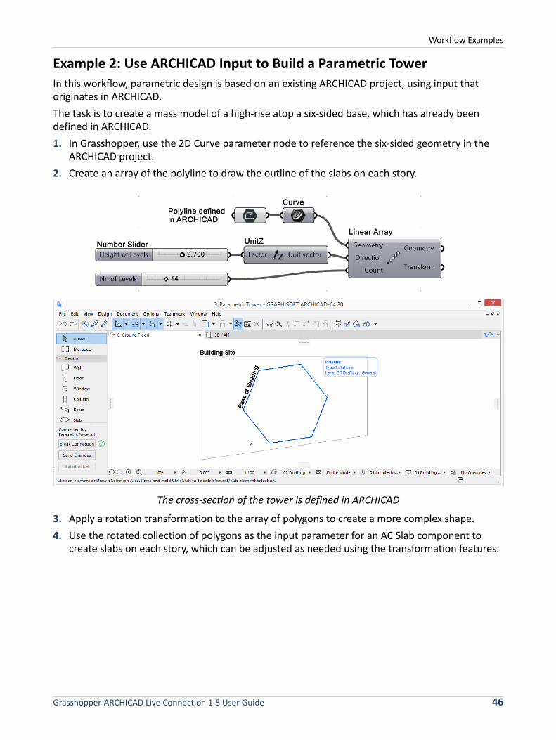
Example 2: Use ARCHICAD Input to Build a Parametric Tower
In this workflow, parametric design is based on an existing ARCHICAD project, using input that originates in ARCHICAD.
The task is to create a mass model of a high-rise atop a six-sided base, which has already been defined in ARCHICAD.
1. In Grasshopper, use the 2D Curve parameter node to reference the six-sided geometry in the ARCHICAD project.
2. Create an array of the polyline to draw the outline of the slabs on each story.
The cross-section of the tower is defined in ARCHICAD
3. Apply a rotation transformation to the array of polygons to create a more complex shape.
4. Use the rotated collection of polygons as the input parameter for an AC Slab component to create slabs on each story, which can be adjusted as needed using the transformation features.
Grasshopper-ARCHICAD Live Connection 1.8 User Guide 46
Workflow Examples
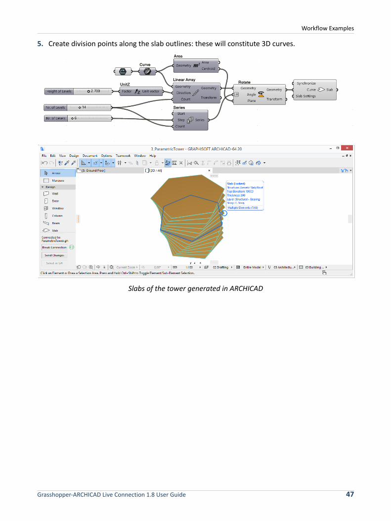
5. Create division points along the slab outlines: these will constitute 3D curves.
Slabs of the tower generated in ARCHICAD
Grasshopper-ARCHICAD Live Connection 1.8 User Guide 47
Workflow Examples
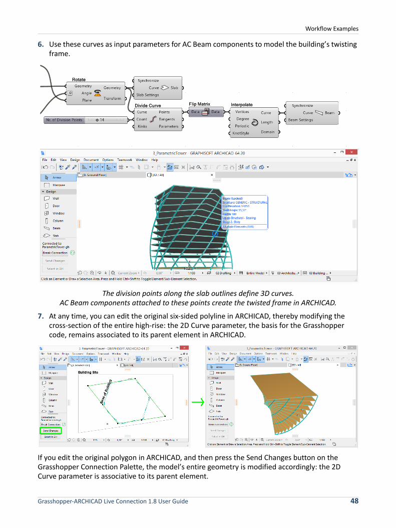
6. Use these curves as input parameters for AC Beam components to model the building’s twisting frame.
The division points along the slab outlines define 3D curves.AC Beam components attached to these points create the twisted frame in ARCHICAD.
7. At any time, you can edit the original six-sided polyline in ARCHICAD, thereby modifying the cross-section of the entire high-rise: the 2D Curve parameter, the basis for the Grasshopper code, remains associated to its parent element in ARCHICAD.
If you edit the original polygon in ARCHICAD, and then press the Send Changes button on the Grasshopper Connection Palette, the model’s entire geometry is modified accordingly: the 2D Curve parameter is associative to its parent element.
Grasshopper-ARCHICAD Live Connection 1.8 User Guide 48

Workflow Examples
8. To change the cross-section of a Beam, attach a Beam Settings Node to the Beam component’s Beam Settings input. From the node’s context menu, click on “Structure of ARCHICAD Beam”, and select Complex Profile. As a result, the set of input parameters of the Beam Settings input is modified and now includes the “Profile” parameter on the left side.
9. Attach a Profile Input Node to the Profile parameter. Click on the right side of the Input Node to bring up the Profile Selection palette, which lists all the profiles defined in the ARCHICAD project. In the upper left of this palette, deselect the Wall and Column elements, so that only profiles defined for Beams are visible, making it easier to choose the right one.
Grasshopper-ARCHICAD Live Connection 1.8 User Guide 49

Important Notes
Important Notes
Parametric Behavior of Generated Elements
• Unlike geometry that is embedded using Rhino’s “Bake” command, elements generated in ARCHICAD remain associated to their generating code. Grasshopper uses an ID-based method to retain its connection to elements placed in ARCHICAD. If the Grasshopper file is modified, the ARCHICAD-Grasshopper Connection Tool will update the corresponding elements in ARCHICAD.
• Elements generated by Design or Document Components in ARCHICAD are not just previews: they are real, editable ARCHICAD elements. When Grasshopper creates these elements, their status is locked. After you unlock them (Edit > Locking > Unlock), you can open their Settings dialog in ARCHICAD in the usual way, and modify their parameters. You can also edit the elements graphically.
• The locked status of elements generated by the Grasshopper code is similar to the “preview” status in Rhino. Parameters of locked elements can be modified only through the Grasshopper code. After the elements are unlocked, their parameters can be modified in ARCHICAD.
• By default, a generated AC element’s parameters which are not controlled by the GH code will have the same settings as the Default Settings of the corresponding tool in ARCHICAD at the time the element was generated.
• Certain parameters of generated AC elements (those which are used in the node of the generating component or their Settings nodes) can be edited in Grasshopper, as well as in ARCHICAD after the elements are unlocked. However, the Grasshopper-based parameter control takes priority over that in ARCHICAD as long as the GH-AC Connection is active. If a parameter of an AC component in Grasshopper is assigned a value (e.g. you add a Number Slider), then that value will be applied every time the Grasshopper code is executed. If you previously assigned a custom value to that element parameter in ARCHICAD, then that custom value, too, will be overridden when the Grasshopper code is executed.
Grasshopper-ARCHICAD Live Connection 1.8 User Guide 50
Important Notes
• If you modify the parameter of a generated element in ARCHICAD using the element’s Settings dialog box, and if that parameter is not controlled in Grasshopper (either because the parameter is not available in the generating component or because the parameter has no assigned value in GH), then your modification remains in effect, even if the Grasshopper code is executed.
• If the GH-AC Connection is not active, then the GH code has no effect on the ARCHICAD project. You can then freely modify even those elements originally generated by Grasshopper code. However, once you reactivate the GH-AC Connection, the GH code again takes precedence in terms of controlling the parameters.
• If you use copy-paste to replicate elements in ARCHICAD which were generated from GH code, then the duplicates will lose their connection to the Grasshopper code. Use this method to create and compare various designs by trying different values for the Grasshopper parameters.
• Suspended Connection: As long as a dialog box is open in ARCHICAD, awaiting user input, the connection between Grasshopper and ARCHICAD is suspended. Even if the user changes an input value in Grasshopper, the change will not take effect until the dialog box in ARCHICAD is closed. Feedback on the suspended connection is shown in ARCHICAD’s Grasshopper Palette: the green connection icon stops spinning. In Grasshopper, the nodes with pending input in ARCHICAD’s direction will turn yellow. A message also pops up to inform the user of which dialog must be closed before the Grasshopper ARCHICAD Connection is resumed.
File Handling
• Elements generated by the Grasshopper code are fully functional, native ARCHICAD elements that remain in the project even if the GH code is not available. Thus, an ARCHICAD project that includes elements generated from GH code requires no additional management. It can be saved as usual to any of the available formats. You can reopen the project without any problem even if the original Grasshopper code is not available (the elements generated from GH code will be still be present in the project).
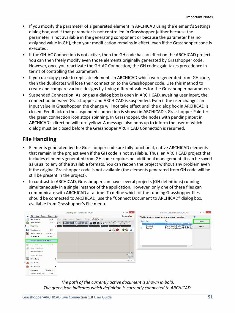
• In contrast to ARCHICAD, Grasshopper can have several projects (GH definitions) running simultaneously in a single instance of the application. However, only one of these files can communicate with ARCHICAD at a time. To define which of the running Grasshopper files should be connected to ARCHICAD, use the “Connect Document to ARCHICAD” dialog box, available from Grasshopper’s File menu.
The path of the currently active document is shown in bold.The green icon indicates which definition is currently connected to ARCHICAD.
Grasshopper-ARCHICAD Live Connection 1.8 User Guide 51
Important Notes
• If you connect an ARCHICAD PLN project to the .GH file which contains the elements’ origin code, the two files recognize each other, and you can continue your parametric design. For this reason, it is recommended to save these file pairs to a single folder, and to use related file names.
• It is currently not possible to use the ARCHICAD-Grasshopper Connection in a Teamwork setup (that is, with ARCHICAD and Rhino installed on different computers). An ARCHICAD file that contains elements generated from GH code can be shared as a Teamwork file, like any other ARCHICAD project, if the GH-AC Connection is disabled.
Grasshopper-ARCHICAD Live Connection 1.8 User Guide 52
Accessing GDL Parameters of ARCHICAD Library Parts
Accessing GDL Parameters of ARCHICAD Library PartsBy default, Grasshopper cannot access the parameters of ARCHICAD Library Parts. However, you can modify a Library Part’s GDL code to allow Grasshopper to access the object’s GDL parameters (see steps below). This is recommended for users familiar with GDL programming.
Note: Geometric Description Language (GDL) is the programming language of ARCHICAD library parts. These library parts, with file format GSM, can be loaded into your ARCHICAD project through the Library Manager. When you open a new project with a default template, a standard ARCHICAD Library is automatically loaded.
To modify an existing Library Part to enable Grasshopper to access its parameters:
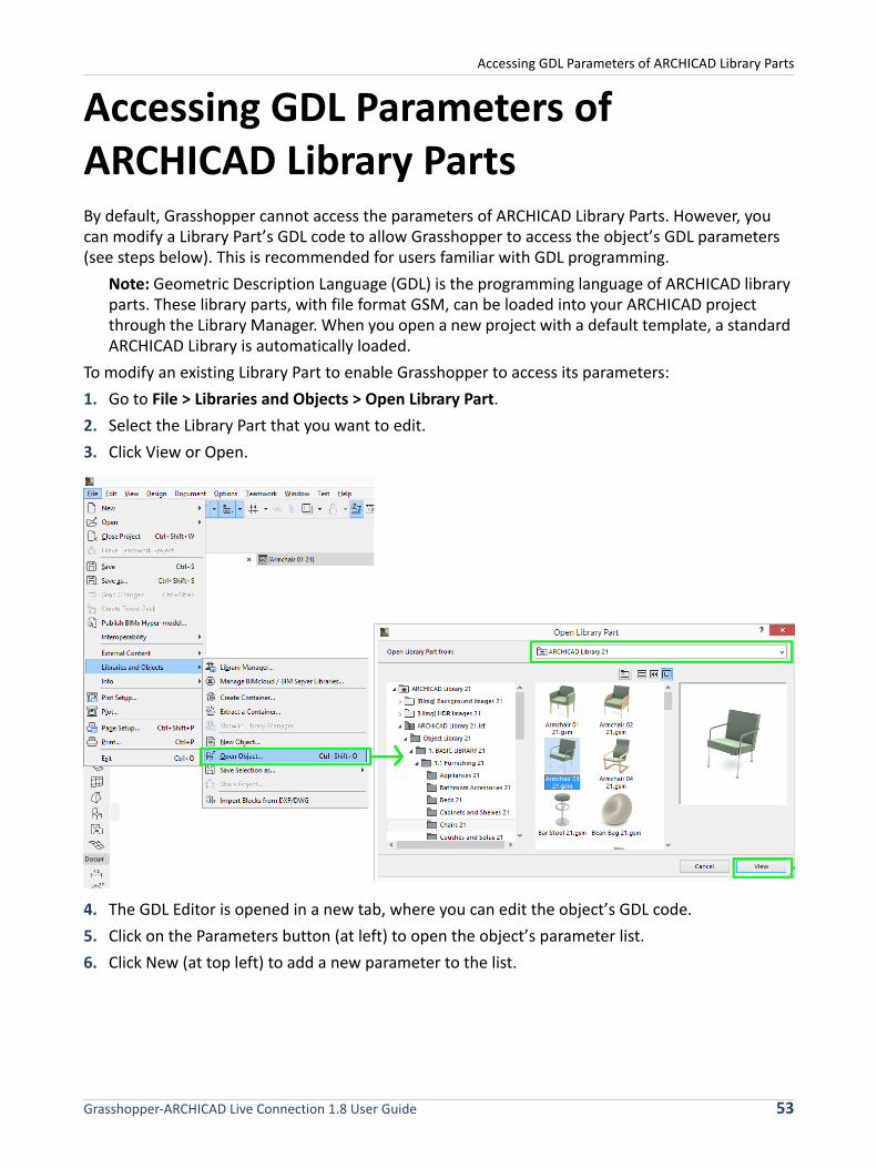
1. Go to File > Libraries and Objects > Open Library Part.
2. Select the Library Part that you want to edit.
3. Click View or Open.
4. The GDL Editor is opened in a new tab, where you can edit the object’s GDL code.
5. Click on the Parameters button (at left) to open the object’s parameter list.
6. Click New (at top left) to add a new parameter to the list.
Grasshopper-ARCHICAD Live Connection 1.8 User Guide 53

Accessing GDL Parameters of ARCHICAD Library Parts
7. Set up this new parameter as follows:
Display: activate the red cross pushbutton to make the variable invisible on the user interface.
Variable: type "ParamcontrolByGrasshopper"
Type: Boolean
Name: enter any name
Value: ON
8. After the new parameter is set, use File > Save as to save the Library Part under a new name to the Embedded Library.
The newly modified, duplicate element is now available in Grasshopper.
9. In Grasshopper, place an Object Settings Node on the canvas.
10. From the context menu, choose Select ARCHICAD Library Part.
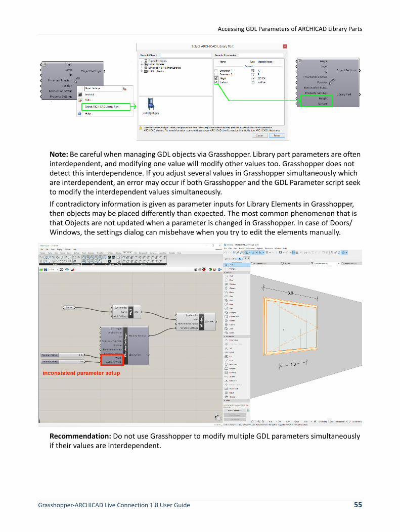
11. From the appearing dialog, browse for the new element. Since Grasshopper detects the ParamcontrolByGrasshopper parameter, the object’s GDL parameters are selectable on the right. Every parameter that you check here will (after you click Select in the dialog box) appear as an input parameter on the left side of the Object Settings Node. From this point on, you can define these GDL parameters, too, in Grasshopper.
Grasshopper-ARCHICAD Live Connection 1.8 User Guide 54
Accessing GDL Parameters of ARCHICAD Library Parts
Note: Be careful when managing GDL objects via Grasshopper. Library part parameters are often interdependent, and modifying one value will modify other values too. Grasshopper does not detect this interdependence. If you adjust several values in Grasshopper simultaneously which are interdependent, an error may occur if both Grasshopper and the GDL Parameter script seek to modify the interdependent values simultaneously.
If contradictory information is given as parameter inputs for Library Elements in Grasshopper, then objects may be placed differently than expected. The most common phenomenon that is that Objects are not updated when a parameter is changed in Grasshopper. In case of Doors/Windows, the settings dialog can misbehave when you try to edit the elements manually.
Recommendation: Do not use Grasshopper to modify multiple GDL parameters simultaneously if their values are interdependent.
Grasshopper-ARCHICAD Live Connection 1.8 User Guide 55


![INTRODUCTION TO GRASSHOPPER - Amazon S3s3.amazonaws.com/mcneel/grasshopper/Grasshopper_Intro_Outline.pdf · Introduction to Grasshopper-[GH-01] INTRODUCTION TO GRASSHOPPER Block 5-Day](https://img.dokumen.tips/doc/110x75/5ada38217f8b9a137f8d3089/introduction-to-grasshopper-amazon-s3s3-to-grasshopper-gh-01-introduction-to.jpg)