Embed Size (px)
Citation preview
GOVERNMENT OF INDIA
MINISTRY OF RAILWAYS
TECHNICAL SPECIFICATION
FOR
FITTINGS FOR 25 Kv a.c. OHE
SPECIFICATION No. ETI/OHE/49(9/95)
RESEARCH DESIGN & STANDARDS ORGANISATION
MANAK NAGAR, LUCKNOW- 226011
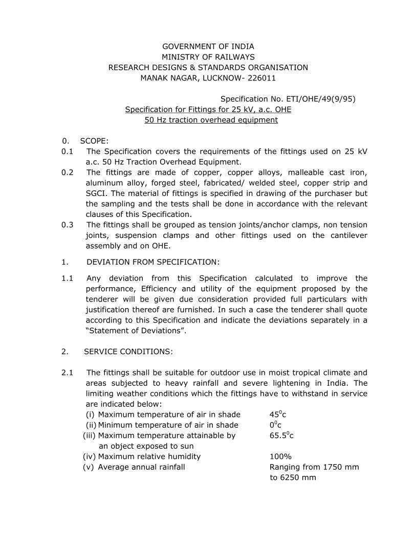
GOVERNMENT OF INDIA
MINISTRY OF RAILWAYS
RESEARCH DESIGNS & STANDARDS ORGANISATION
MANAK NAGAR, LUCKNOW- 226011
Specification No. ETI/OHE/49(9/95)
Specification for Fittings for 25 kV, a.c. OHE
50 Hz traction overhead equipment
0. SCOPE:
0.1 The Specification covers the requirements of the fittings used on 25 kV
a.c. 50 Hz Traction Overhead Equipment.
0.2 The fittings are made of copper, copper alloys, malleable cast iron,
aluminum alloy, forged steel, fabricated/ welded steel, copper strip and
SGCI. The material of fittings is specified in drawing of the purchaser but
the sampling and the tests shall be done in accordance with the relevant
clauses of this Specification.
0.3 The fittings shall be grouped as tension joints/anchor clamps, non tension
joints, suspension clamps and other fittings used on the cantilever
assembly and on OHE.
1. DEVIATION FROM SPECIFICATION:
1.1 Any deviation from this Specification calculated to improve the
performance, Efficiency and utility of the equipment proposed by the
tenderer will be given due consideration provided full particulars with
justification thereof are furnished. In such a case the tenderer shall quote
according to this Specification and indicate the deviations separately in a
“Statement of Deviations”.
2. SERVICE CONDITIONS:
2.1 The fittings shall be suitable for outdoor use in moist tropical climate and
areas subjected to heavy rainfall and severe lightening in India. The
limiting weather conditions which the fittings have to withstand in service
are indicated below:
(i) Maximum temperature of air in shade 450c
(ii) Minimum temperature of air in shade 00c
(iii) Maximum temperature attainable by 65.50c
an object exposed to sun
(iv) Maximum relative humidity 100%
(v) Average annual rainfall Ranging from 1750 mm
to 6250 mm
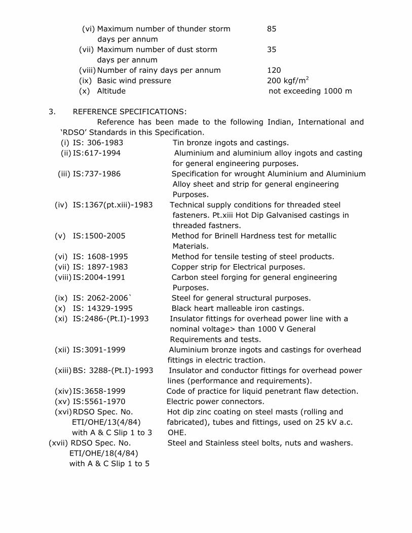
(vi) Maximum number of thunder storm 85
days per annum
(vii) Maximum number of dust storm 35
days per annum
(viii) Number of rainy days per annum 120
(ix) Basic wind pressure 200 kgf/m2
(x) Altitude not exceeding 1000 m
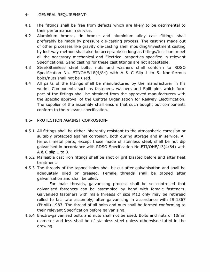
3. REFERENCE SPECIFICATIONS:
Reference has been made to the following Indian, International and
‘RDSO’ Standards in this Specification.
(i) IS: 306-1983 Tin bronze ingots and castings.
(ii) IS:617-1994 Aluminium and aluminium alloy ingots and casting
for general engineering purposes.
(iii) IS:737-1986 Specification for wrought Aluminium and Aluminium
Alloy sheet and strip for general engineering
Purposes.
(iv) IS:1367(pt.xiii)-1983 Technical supply conditions for threaded steel
fasteners. Pt.xiii Hot Dip Galvanised castings in
threaded fastners.
(v) IS:1500-2005 Method for Brinell Hardness test for metallic
Materials.
(vi) IS: 1608-1995 Method for tensile testing of steel products.
(vii) IS: 1897-1983 Copper strip for Electrical purposes.
(viii) IS:2004-1991 Carbon steel forging for general engineering
Purposes.
(ix) IS: 2062-2006` Steel for general structural purposes.
(x) IS: 14329-1995 Black heart malleable iron castings.
(xi) IS:2486-(Pt.I)-1993 Insulator fittings for overhead power line with a
nominal voltage> than 1000 V General
Requirements and tests.
(xii) IS:3091-1999 Aluminium bronze ingots and castings for overhead
fittings in electric traction.
(xiii) BS: 3288-(Pt.I)-1993 Insulator and conductor fittings for overhead power
lines (performance and requirements).
(xiv) IS:3658-1999 Code of practice for liquid penetrant flaw detection.
(xv) IS:5561-1970 Electric power connectors.
(xvi) RDSO Spec. No. Hot dip zinc coating on steel masts (rolling and
ETI/OHE/13(4/84) fabricated), tubes and fittings, used on 25 kV a.c.
with A & C Slip 1 to 3 OHE.
(xvii) RDSO Spec. No. Steel and Stainless steel bolts, nuts and washers.
ETI/OHE/18(4/84)
with A & C Slip 1 to 5
4- GENERAL REQUIREMENT-
4.1 The fittings shall be free from defects which are likely to be detrimental to
their performance in service.
4.2 Aluminium bronze, tin bronze and aluminium alloy cast fittings shall
preferably be made by pressure die-casting process. The castings made out
of other processes like gravity die-casting shell moulding/investment casting
by lost way method shall also be acceptable so long as fittings/test bars meet
all the necessary mechanical and Electrical properties specified in relevant
Specifications. Sand casting for these cast fittings are not acceptable.
4.3 Steel/Stainless steel bolts, nuts and washers shall conform to RDSO
Specification No. ETI/OHE/18(4/84) with A & C Slip 1 to 5. Non-ferrous
bolts/nuts shall not be used.
4.4 All parts of the fittings shall be manufactured by the manufacturer in his
works. Components such as fasteners, washers and Split pins which form
part of the fittings shall be obtained from the approved manufacturers with
the specific approval of the Central Organisation for Railway Electrification.
The supplier of the assembly shall ensure that such bought out components
conform to the relevant specification.
4.5- PROTECTION AGAINST CORROSION-
4.5.1 All fittings shall be either inherently resistant to the atmospheric corrosion or
suitably protected against corrosion, both during storage and in service. All
ferrous metal parts, except those made of stainless steel, shall be hot dip
galvanised in accordance with RDSO Specification No.ETI/OHE/13(4/84) with
A & C slip 1 to 3.
4.5.2 Malleable cast iron fittings shall be shot or grit blasted before and after heat
treatment.
4.5.3 The threads of the tapped holes shall be cut after galvanisation and shall be
adequately oiled or greased. Female threads shall be tapped after
galvanisation and shall be oiled.
For male threads, galvanising process shall be so controlled that
galvanised fasteners can be assembled by hand with female fasteners.
Galvanised fasteners with male threads of size M12 only may be rethread
rolled to facilitate assembly, after galvanising in accordance with IS:1367
(Pt.xiii)-1983. The thread of all bolts and nuts shall be formed conforming to
their relevant Specification before galvanising.
4.5.4 Electro-galvanised bolts and nuts shall not be used. Bolts and nuts of 10mm
diameter and less shall be of stainless steel unless otherwise stated in the
drawing.
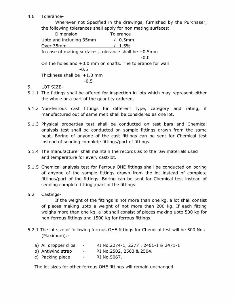
4.6 Tolerance-
Wherever not Specified in the drawings, furnished by the Purchaser,
the following tolerances shall apply for non mating surfaces:
Dimension Tolerance
Upto and including 35mm +/- 0.5mm
Over 35mm +/- 1.5%
In case of mating surfaces, tolerance shall be +0.5mm
-0.0
On the holes and +0.0 mm on shafts. The tolerance for wall
-0.5
Thickness shall be +1.0 mm
-0.5
5. LOT SIZE-
5.1.1 The fittings shall be offered for inspection in lots which may represent either
the whole or a part of the quantity ordered.
5.1.2 Non-ferrous cast fittings for different type, category and rating, if
manufactured out of same melt shall be considered as one lot.
5.1.3 Physical properties test shall be conducted on test bars and Chemical
analysis test shall be conducted on sample fittings drawn from the same
heat. Boring of anyone of the cast fittings can be sent for Chemical test
instead of sending complete fittings/part of fittings.
5.1.4 The manufacturer shall maintain the records as to the raw materials used
and temperature for every cast/lot.
5.1.5 Chemical analysis test for Ferrous OHE fittings shall be conducted on boring
of anyone of the sample fittings drawn from the lot instead of complete
fittings/part of the fittings. Boring can be sent for Chemical test instead of
sending complete fittings/part of the fittings.
5.2 Castings-
If the weight of the fittings is not more than one kg, a lot shall consist
of pieces making upto a weight of not more than 200 kg. If each fitting
weighs more than one kg, a lot shall consist of pieces making upto 500 kg for
non-ferrous fittings and 1500 kg for ferrous fittings.
5.2.1 The lot size of following ferrous OHE fittings for Chemical test will be 500 Nos
(Maximum):-
a) All dropper clips - RI No.2274-1, 2277 , 2461-1 & 2471-1
b) Antiwind strap - RI No.2502, 2503 & 2504.
c) Packing piece - RI No.5067.
The lot sizes for other ferrous OHE fittings will remain unchanged.
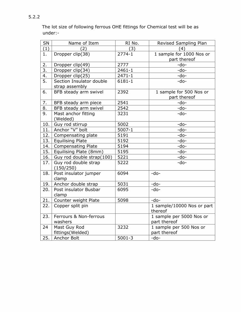
5.2.2
The lot size of following ferrous OHE fittings for Chemical test will be as
under:-
SN Name of Item RI No. Revised Sampling Plan
(1) (2) (3) (4)
1. Dropper clip(38) 2774-1 1 sample for 1000 Nos or
part thereof
2. Dropper clip(49) 2777 -do-
3. Dropper clip(34) 2461-1 -do-
4. Dropper clip(25) 2471-1 -do-
5. Section Insulator double strap assembly
6181-1 -do-
6. BFB steady arm swivel 2392 1 sample for 500 Nos or part thereof
7. BFB steady arm piece 2541 -do-
8. BFB steady arm swivel 2542 -do-
9. Mast anchor fitting
(Welded)
3231 -do-
10. Guy rod stirrup 5002 -do-
11. Anchor “V” bolt 5007-1 -do-
12. Compensating plate 5191 -do-
13. Equilising Plate 5192 -do-
14. Compensating Plate 5194 -do-
15. Equilising Plate (8mm) 5195 -do-
16. Guy rod double strap(100) 5221 -do-
17. Guy rod double strap
(150/250)
5222 -do-
18. Post insulator jumper clamp
6094 -do-
19. Anchor double strap 5031 -do-
20. Post insulator Busbar clamp
6095 -do-
21. Counter weight Plate 5098 -do-
22. Copper split pin 1 sample/10000 Nos or part
thereof
23. Ferrours & Non-ferrous
washers
1 sample per 5000 Nos or
part thereof
24 Mast Guy Rod
fittings(Welded)
3232 1 sample per 500 Nos or
part thereof
25. Anchor Bolt 5001-3 -do-
5.3 Three test bars shall be made for each cast/melt for tensile and elongation,
tests. The test bars shall bear identification mark of the lot and date of melt.
5.4 Forged Welded Fittings-The lot of forged, welded or fabricated ferrous fittings
shall consist of not more than 500 numbers of fittings.
5.5 Copper/Aluminum Alloy Strip Formed Fitting-The lot of such fittings weighing
each upto 50 gm shall not exceed 2500 numbers while for the fittings
weighing more than 50 gm, the lot, shall be restricted to 1000 numbers.
5.5.1 The lot size of following non-ferrous copper strips for chemical test will be
1000 Nos (Maximum):-
a) Packing shaddle - RI No. 1174
b) Briddle wire sleeve- RI No. 2125.
The lot sizes for other Non-ferrous OHE fittings will remain unchanged.
5.5.2 The lot size for following non-ferrous copper fittings for Chemical test will be
as under:
a) Locking wire RI No.1182- 5000 Nos.
b) Contact wire swivel clip pin RI No.1222- 5000 Nos.
c) Suspension clamp lock plate RI No.1163- 2500 Nos.
5.6 Sample size-
5.6.1 The number of fittings to be selected at random from the lot shall be in
accordance with column 1 and 2 of table given below. If required, additional
number of fittings as given in column 3 of table given below shall be selected
at random to satisfy the criteria for conformity in accordance with clause
5.6.2 below.
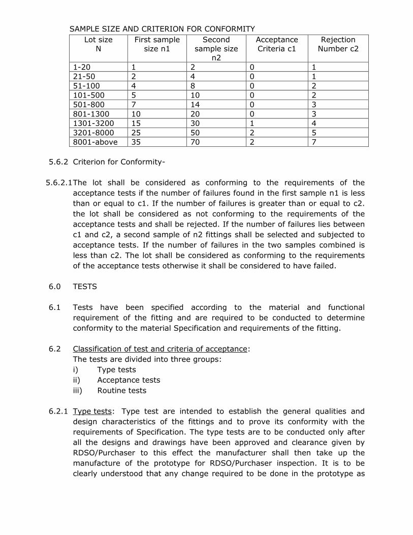
SAMPLE SIZE AND CRITERION FOR CONFORMITY
Lot size
N
First sample
size n1
Second
sample size n2
Acceptance
Criteria c1
Rejection
Number c2
1-20 1 2 0 1
21-50 2 4 0 1
51-100 4 8 0 2
101-500 5 10 0 2
501-800 7 14 0 3
801-1300 10 20 0 3
1301-3200 15 30 1 4
3201-8000 25 50 2 5
8001-above 35 70 2 7
5.6.2 Criterion for Conformity-
5.6.2.1 The lot shall be considered as conforming to the requirements of the
acceptance tests if the number of failures found in the first sample n1 is less
than or equal to c1. If the number of failures is greater than or equal to c2.
the lot shall be considered as not conforming to the requirements of the
acceptance tests and shall be rejected. If the number of failures lies between
c1 and c2, a second sample of n2 fittings shall be selected and subjected to
acceptance tests. If the number of failures in the two samples combined is
less than c2. The lot shall be considered as conforming to the requirements
of the acceptance tests otherwise it shall be considered to have failed.
6.0 TESTS
6.1 Tests have been specified according to the material and functional
requirement of the fitting and are required to be conducted to determine
conformity to the material Specification and requirements of the fitting.
6.2 Classification of test and criteria of acceptance:
The tests are divided into three groups:
i) Type tests
ii) Acceptance tests
iii) Routine tests
6.2.1 Type tests: Type test are intended to establish the general qualities and
design characteristics of the fittings and to prove its conformity with the
requirements of Specification. The type tests are to be conducted only after
all the designs and drawings have been approved and clearance given by
RDSO/Purchaser to this effect the manufacturer shall then take up the
manufacture of the prototype for RDSO/Purchaser inspection. It is to be
clearly understood that any change required to be done in the prototype as
required by RDSO/Purchaser shall be done expeditiously. Each test shall be
made on 3 samples. If the sample fails in any of the tests the production of
further fittings shall be stopped till further investigation and improvements in
the manufacturing procedure done.
6.2.2 Acceptance tests: Acceptance tests are carried out to verify the quality of
material and workmanship for acceptance of the lot.
6.2.3 Routine tests: Routine tests are carried out on each fitting from the lot to
check the requirements which are likely to vary during production. The
defective once are rejected. If 10% or more fittings fail to meet the
requirement of the routine test the entire lot shall be rejected.
6.3 Bulk Manufacture: Only after clear written approval of the results of the tests
on the prototype is communicated by RDSO/Purchaser to the manufacturer,
shall be take up bulk manufacture of the fittings which shall be strictly with
the same material and process as adopted for the prototype. In no
circumstances shall material other than those approved in the
design/drawings and/or the prototype be used for bulk manufacture on the
plea that they had been obtained prior to the approval of the prototype.
6.4 Inspection: Before giving the call to RDSO/Purchaser for inspection and
testing of the prototype of the system, the manufacturer shall submit a
detailed test schedule consisting of schematic circuit diagrams for each of the
tests, nature of the test, venue of the test, duration of each test and the total
number of days required to complete the test at one stretch. Once schedule
is approved, the test shall invariably be done accordingly. However, during
the process of type testing or even later, RDSO/Purchaser’s during the
process of type testing or even later, RDSO/Purchaser’s representative
reserves the right to conduct any/additional tests besides those specified
herein, on any equipment/sub-system or system so as to test the system to
his satisfaction or for gaining additional information and knowledge. In case
any despute or disagreement arises between the manufacturer and the
RDSO/Purchaser’s representative during the process of testing as regards the
type test and/or the interpretation and acceptability of the type test results,
it shall be brought to the notice of the director General (Traction
Installation), RDSO/Purchaser as the case may be whose decision shall be
final and binding.
6.5 Inspector’s responsibility: The inspecting authority shall maintain a proper
record of the number of fittings offered for inspection in each lot, the number
of fittings on which acceptance tests were done and the results thereof,
indicating the number of fittings, if any, rejected and reasons therefore.
These records or copies thereof shall be furnished to the consignee as well as
to the ordering/purchasing authority. The inspecting authority shall, during
his inspection carefully check that proper records of routine tests and
prescribed ‘quality assurance checks’ done at the manufacture’s works are
maintained in the required manner.
7. MATERIAL SPECIFICATION-
7.1 Aluminium Bronze: Aluminium bronze alloy used for the fittings shall
conform to IS: 3091-1999. The relevant extracts of the specification are
given in Appendix ’A’.
7.2 Malleable cast iron: The malleable cast iron fittings shall conform to Grade
BM: 340 of IS: 14329-1995. Relevant extracts of the specification are given
in appendix- ‘B’.
7.3 Tin-bronze: The tine bronze fittings shall conform to the IS: 306-1983. The
relevant extracts are given in Appendix ‘C’.
7.4 Aluminium alloy: The aluminium alloy fittings shall conform to Grade 4600 of
IS: 617-1994. The extract are given in Appendix ‘D’.
7.5 Forged steel: The material of forged steel fittings shall conform to class 2 of
IS: 2004-1991, unless otherwise specified. The relevant extracts are given in
Appendix ‘E’.
7.6 Fabricated steel: The material of fabricated steel fittings unless otherwise
stated on the drawings shall conform to Grade A of IS: 2062-2006. The
relevant extracts are given in Appendix ‘F’.
7.7 Copper strip fittings: The material of fittings formed by copper strip shall
conform to IS:1897-1983. The relevant extracts are given in Appendix ‘G’.
7.8 Aluminium or aluminium alloy strips/sheets: The material of strips shall
conform to Grade 52000, condition H2 of IS:737-1986. The relevant extracts
are given in Appendix ‘H’.
Note “:Electrical Resistivity test specified under para-9of IS:1897-1983 shall
not be applicable for catenary dropper clip(RI-1192) and bridle wire dropper
clip(RI-1194)”
7.9 Due to non-availability of flat size M12x35 mm, the flat size M12x38 mm can
be used in lieu, for following fittings:-
a) Post Insulator Jamper clamp - RI – 6094
b) Post Insulator Busbar clamp - RI – 6095
8.0 CONDUCTOR END CLAMPS, MID SPAN TENSION JOINTS ANCHOR FITTINGS
AND TURN-BUCKLES (9-TONNE ADJUSTER)
8.1 Fittings for clamping the conductors, which are in tension, at the ends &
their mid-span splices are called end clamps and tension joints respectively
and are covered in this group.
8.2 Requirements: End clamps and tension joints shall be manufactured and
finished so as to avoid sharp radius of curvature, ridges and excrescenes
which might lead to localised pressure and damage to the conductor and
fitting due to vibration in service. They shall withstand the tests prescribed.
8.3 The end clamps and tension joints may be of aluminium alloy casting,
aluminium bronze casting, malleable iron casting or forged/fabricated steel
as specified in the purchaser’s drawings. The material shall conform to the
relevant Specifications.
8.4 The fitting may be bolted type, cone type, wedge type or compression type,
as specified in purchaser’s drawing.
8.5 Tests:
8.5.1 Type Tests:
a) Visual inspection (see Cl.11.1.)
b) Dimensional verification (see Cl.11.2)
c) Chemical composition test (see Cl.11.3)
d) Physical properties test (see Cl.11.4)
e) Failing load test (see Cl.11.5)
f) Radiographic test (only for castings) (see Cl.11.6)
g) Electric resistance test
(for splices only) (see Cl.11.8)
h) Temperature rise test
(for splices only) (see Cl.11.9)
i) Galvanising test (for ferrous
fittings only) (see Cl.11.10)
j) Dye penetration test (see Cl.11.12)
k) Hardness test (for MCI fittings) (see Cl.11.14)
8.5.2 Acceptance Tests:
a) Visual inspection (see Cl.11.1)
b) Dimensional verification (see Cl.11.2)
c) Chemical composition test (see Cl.11.3)
d) Physical properties test (see Cl.11.4)
e) Failing load test (see Cl.11.5)
f) Galvanising test (for ferrous
fittings only) (see Cl.11.10)
g) Dye penetration test (see Cl.11.12)
h) Hardness test (for MCI fittings) (see Cl.11.14)
8.5.3 Samples taken in accordance with Clause 5.6 shall be subjected to all tests
listed under ‘Acceptance Tests’ except for chemical composition test and
physical properties test which should be conducted in accordance with Clause
11.3 and 11.4 respectively.
8.5.4 Routine Tests:
a) Visual inspection (see Cl.11.1)
b) Routine verification of dimension (see Cl.11.13)
c) Dye penetration test for fittings
listed in Appendix ‘J’ only. (see Cl.11.12)
9.0 NON-TENSION JOINTS (PARALLEL GROOVE AND TERMINAL CLAMPS)
9.1 Non-Tension Joints: The fittings used on the overhead conductors for
electrical continuity which are not subjected to tension are classified as non-
tension joints. Such fittings include parallel groove clamps and terminal
clamps of jumper assemblies.
9.2 General Requirements: Non-tension joints shall be designed so that they
meet the requirements of the normal service conditions. A rated current shall
be assigned to every joint which shall be the criterion for electrical type tests.
Fittings intended to connect conductors of two dis-similar materials shall be
so designed that harmful bimetallic corrosion when erected in exposed
atmospheric condition is minimised.
9.2.1 Fittings for non-tension joints shall be manufactured and finished so as to
avoid sharp radius of curvature, ridges which may lead to the localised
pressure or damage to the conductor in service.
9.3 Non-tension joints are made of tin-bronze, Aluminium bronze,Aluminium
alloy or copper as specified by the purchaser. The material shall conform to
the relevant clauses of this specification.

9.4 Non-tension joint fittings are generally of bolted type, though there may be
some fittings of crimped type or soldered type. All fittings are subjected to
the tests as specified in relevant paras of this specification.
9.5 Tests:
9.5.1 Type Tests:
a) Visual inspection (see Cl.11.1)
b) Dimensional verification (see Cl.11.2)
c) Chemical composition test (see Cl.11.3)
d) Physical properties test (see Cl.11.4)
e) Radiographic test
(Only for castings) (see Cl.11.6)
f) Slip test (see Cl.11.7)
g) Electric resistance test (see Cl.11.8)
h) Temperature rise test (see Cl.11.9)
i) Dye penetration test (see Cl.11.12)
9.5.2 Acceptance test:
a) Visual inspection (see Cl.11.1)
b) Dimensional verification (see Cl.11.2)
c) Chemical composition test (see Cl.11.3)
d) Physical properties test (see Cl.11.4)
e) Dye penetration test (see Cl.11.12)
9.5.2.1 Samples taken in accordance with clause 5.6 shall be subjected to all tests
listed under ‘Acceptance test’ except for chemical composition tests and
physical properties test, which should be conducted in accordance with clause
11.3 and 11.4 respectively.
9.5.3 Routine Tests:
a) Visual inspection (see Cl.11.1)
b) Routine verification of dimensions (see Cl.11.13)
10. SUSPENSION CLAMPS AND OTHER CANTILEVER ASSEMBLY FITTINGS.
10.1 Fittings which are used on the cantilever assembly and the suspension of
suspension of conductors are covered in this group.
10.2 General Requirements:
The clamps and fittings shall be so designed and manufactured that the
effect of vibrations, both on the conductors/cantilever assembly and fitting
itself, are minimized.
The suspension clamps, additionally, shall be manufactured and finished so
as to avoid sharp radius of curvature, ridges and excrescences which might
lead to the localized pressure or damage to the conductor in service. The
suspension clamps shall permit the conductor to slip before failure of
conductor occurs. The clamp shall have sufficient contact surface to minimize
damage by fault currents.
10.3 Tests:
10.3.1Type tests:
a) Visual inspection (see Cl.11.1)
b) Dimensional verification (see Cl.11.2)
c) Chemical composition test (see Cl.11.3)
d) Physical properties test (see Cl.11.4)
e) Failing load test (see Cl.11.5)
f) Radiographic test (see Cl.11.6)
(Only for casting)
g) Slip test
(Only for suspension clamp). (see Cl.11.7)
h) Galvanising test (for ferrous
fittings only) (see Cl.11.10)
i) Assembly test (for contact wire
dropper clip and swivel clips only) (see Cl.11.11)
j) Dye penetration test (see Cl.11.12)
k) Hardness test (for MCI fittings) (see Cl.11.14)
10.3.2 Acceptance Test:
a) Visual inspection (see Cl.11.1)
b) Dimensional verification (see Cl.11.2)
c) Chemical composition test (see Cl.11.3)
d) Physical properties test (see Cl.11.4)
e) Failing load test (see Cl.11.5)
f) Slip test (for suspension clamp)
g) Galvanising test (see Cl.11.7)
(for ferrous Fitting only) (see Cl.11.10)
h) Assembly test (for contact wire
Dropper clip and swivel clips only) (see Cl.11.11)
i) Dye penetration test (see Cl.11.12)
j) Hardness test (for MCI fittings) (see Cl.11.14)
10.3.2.1 Samples taken in accordance with clause 5.6 shall be subjected to all
tests listed under ‘Acceptance tests’ except for chemical composition test
and physical properties test which should be conducted in accordance with
clause 11.3 and 11.4 respectively.
10.3.3 Routine test:
a) Visual inspection (see Cl.11.1)
b) Routine verification of dimension (see Cl.11.13)
c) Dye penetration test (for fittings
Listed in Appendix ‘J’ only) (see Cl.11.12)
11. TEST METHODS:
11.1 Visual Inspection:
All fittings shall be examined visually for good work-manship and
smooth finish including marking as specified in Purchaser’s drawings and for
freedom from defects stipulated in relevant specifications. Galvinased fittings
shall be checked in accordance with clause-4.5 of RDSO Specification
No.ETI/OHE/13(4/84) with A & C slip 1 to 3 for visual defects and fittings
having defects mentioned in Appendix ‘A’ of that specification shall be
rejected.
11.2 Dimensional Verification:
All dimensions of fittings shall be verified with the help of gauges,
calipers and micrometers to check that they conform with the approved
drawings. Thread gauges shall be used to check threads wherever provided if
any. Go and No-Go gauges are used for checking of dimensions, the drawing
for such gauges shall be got approved by the manufacturer before use by the
inspecting authority.
11.3 Chemical Composition Test:
The Chemical composition of the material specified shall be tested in
accordance with the relevant Specification mentioned in clause-7 .In case of
casting, the tests shall be done only on one sample fittings of each melt/lot
by taking boring of any one of cast fittings. Material shall conform to the
requirements specified in the relevant Specification. In case of
forged/welded/ fabricated fittings, the test shall be carried out on one sample
each of raw material and concerned fittings upto a lot of 200 Nos. and on two
samples each of raw material and fittings upto a lot of 500 Nos. In case of
Copper/Aluminium strip formed fittings. the test shall be carried out on the
fittings samples on every 500 Nos. or fraction thereof a lot.
11.4 Physical Properties Test:
11.4.1 In the case of castings the tests for mechanical properties shall be conducted
on the test bars/pieces made in accordance with the relevant Specification
(Clause 7.) (See relevant Appendices also).
If one test piece fails in any test, two more test pieces shall be tested.
The samples shall be deemed to have passed the tests if there is no failure in
the retest.
11.4.1.1In case of malleable cast iron (MCI) fittings, the micro-structure (ref. Clause
B.2) and hardness (ref. Clause B.5) shall also be tested.
11.4.2 In case of forged/fabricated/welded fittings physical properties tests shall be
conducted in accordance with the relevant Specifications on one sample upto
a lot of 100 Nos. and on 3 samples for a lot exceeding 100 Nos. which should
be selected at random. If one exceeding 100 nos which should be selected at
random. If one sample fails in any test, double the number of test pieces
shall be tested. The samples shall be deemed to have passed the tests if
there is no failure in the retest.
11.4.3 In case of Copper/Aluminium strip formed fittings physical properties test on
one sample upto a lot of 500 Nos. shall be conducted.
11.5 Failing Load Test:
11.5.1 For Conductor End Clamps, Mid Span Tension Joints and Splices.
11.5.1.1 The fittings shall be assembled in accordance with the standard drawings on
the conductors of the size and type with which it is meant to be used. The
assembly shall be held in a tensile testing machine and anchored in a manner
approximating as nearly as possible, to the arrangement used in service. The
compression end clamps shall be compressed on the specified conductor. The
precaution shall be taken to avoid bird caging of the conductor. The length of
conductor between the fittings under test and any other clamp or joint in the
test assembly shall not be less than 100 times the average overage overall
diameter of the conductor.
11.5.1.2 A tensile load of about 50% of the breaking load of the conductor shall be
applied and conductor shall be marked in such a manner in that movement
relative to the fitting can be easily detected. Without any subsequent
adjustment of the fitting, the load shall be steadily increased to 90% of the
breaking load and maintained for one minute. There shall be no movement of
the conductor relative to the fitting due to slip during this period of one
minute.
11.5.1.3 The tensile load shall then be increased until the conductor either slips out of
the fitting under test or snaps or one or more of the component(s), of the
fitting fracture or deform.
11.5.1.4 The fitting shall not break, slip or deform till the conductor breaks. Should
the wire or conductor slip in the fitting or any component of the fitting
fractures or deforms before the failure of conductor the fitting shall be
deemed to have failed in the load test. If the conductor breaks at a load less
than 95% of its specified breaking strength, the test shall be repeated.
11.5.1.5 After the test it should be possible to dismantle the fitting without difficulty
and without recourse to any tools other than those normally employed for
assembling them.
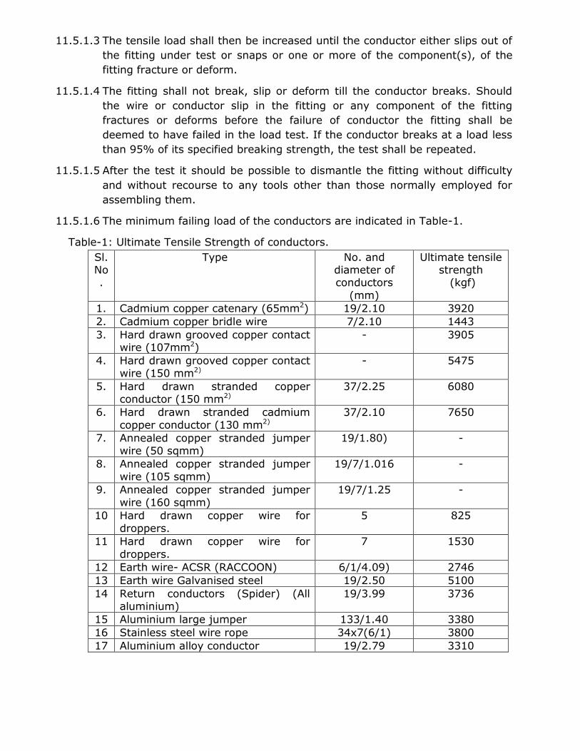
11.5.1.6 The minimum failing load of the conductors are indicated in Table-1.
Table-1: Ultimate Tensile Strength of conductors.
Sl.No.
Type No. and diameter of conductors
(mm)
Ultimate tensile strength (kgf)
1. Cadmium copper catenary (65mm2) 19/2.10 3920
2. Cadmium copper bridle wire 7/2.10 1443
3. Hard drawn grooved copper contact wire (107mm2)
- 3905
4. Hard drawn grooved copper contact wire (150 mm2)
- 5475
5. Hard drawn stranded copper conductor (150 mm2)
37/2.25 6080
6. Hard drawn stranded cadmium
copper conductor (130 mm2)
37/2.10 7650
7. Annealed copper stranded jumper
wire (50 sqmm)
19/1.80) -
8. Annealed copper stranded jumper
wire (105 sqmm)
19/7/1.016 -
9. Annealed copper stranded jumper
wire (160 sqmm)
19/7/1.25 -
10 Hard drawn copper wire for
droppers.
5 825
11 Hard drawn copper wire for
droppers.
7 1530
12 Earth wire- ACSR (RACCOON) 6/1/4.09) 2746
13 Earth wire Galvanised steel 19/2.50 5100
14 Return conductors (Spider) (All aluminium)
19/3.99 3736
15 Aluminium large jumper 133/1.40 3380
16 Stainless steel wire rope 34x7(6/1) 3800
17 Aluminium alloy conductor 19/2.79 3310
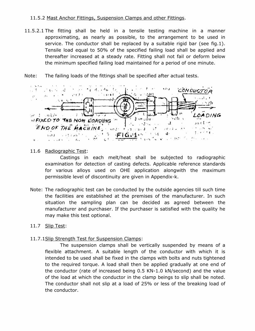
11.5.2 Mast Anchor Fittings, Suspension Clamps and other Fittings.
11.5.2.1 The fitting shall be held in a tensile testing machine in a manner
approximating, as nearly as possible, to the arrangement to be used in
service. The conductor shall be replaced by a suitable rigid bar (see fig.1).
Tensile load equal to 50% of the specified failing load shall be applied and
thereafter increased at a steady rate. Fitting shall not fail or deform below
the minimum specified failing load maintained for a period of one minute.
Note: The failing loads of the fittings shall be specified after actual tests.
11.6 Radiographic Test:
Castings in each melt/heat shall be subjected to radiographic
examination for detection of casting defects. Applicable reference standards
for various alloys used on OHE application alongwith the maximum
permissible level of discontinuity are given in Appendix-k.
Note: The radiographic test can be conducted by the outside agencies till such time
the facilities are established at the premises of the manufacturer. In such
situation the sampling plan can be decided as agreed between the
manufacturer and purchaser. If the purchaser is satisfied with the quality he
may make this test optional.
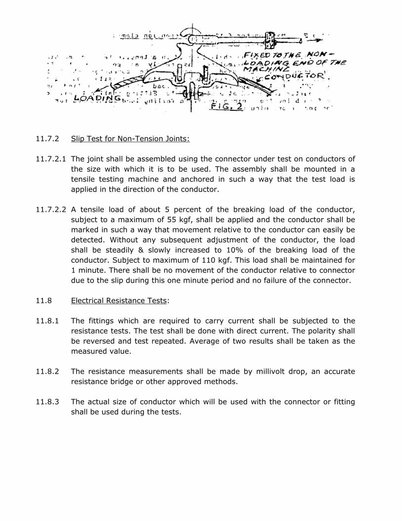
11.7 Slip Test:
11.7.1Slip Strength Test for Suspension Clamps:
The suspension clamps shall be vertically suspended by means of a
flexible attachment. A suitable length of the conductor with which it is
intended to be used shall be fixed in the clamps with bolts and nuts tightened
to the required torque. A load shall then be applied gradually at one end of
the conductor (rate of increased being 0.5 KN-1.0 kN/second) and the value
of the load at which the conductor in the clamp beings to slip shall be noted.
The conductor shall not slip at a load of 25% or less of the breaking load of
the conductor.
11.7.2 Slip Test for Non-Tension Joints:
11.7.2.1 The joint shall be assembled using the connector under test on conductors of
the size with which it is to be used. The assembly shall be mounted in a
tensile testing machine and anchored in such a way that the test load is
applied in the direction of the conductor.
11.7.2.2 A tensile load of about 5 percent of the breaking load of the conductor,
subject to a maximum of 55 kgf, shall be applied and the conductor shall be
marked in such a way that movement relative to the conductor can easily be
detected. Without any subsequent adjustment of the conductor, the load
shall be steadily & slowly increased to 10% of the breaking load of the
conductor. Subject to maximum of 110 kgf. This load shall be maintained for
1 minute. There shall be no movement of the conductor relative to connector
due to the slip during this one minute period and no failure of the connector.
11.8 Electrical Resistance Tests:
11.8.1 The fittings which are required to carry current shall be subjected to the
resistance tests. The test shall be done with direct current. The polarity shall
be reversed and test repeated. Average of two results shall be taken as the
measured value.
11.8.2 The resistance measurements shall be made by millivolt drop, an accurate
resistance bridge or other approved methods.
11.8.3 The actual size of conductor which will be used with the connector or fitting
shall be used during the tests.
11.8.4 For Tension Joints:
The fittings shall be assembled in accordance with the standard
drawing on the conductors of the size and type with which it is to be used.
The electrical resistance shall be measured between two points on the
conductors on either side and 25 mm clear of the fitting. The resistance of
the conductor with splice shall be of the same order as that of the equivalent
length of the conductor. The current connections shall be at a distance of not
less than 50 times of the diameter of the conductor from the fitting and shall
be made so that effective contact is made with all those strands of conductor
which would be taken into account in calculating its equivalent resistance.
11.8.5 For non-tension joints:
The resistance of 1.25m of a conductor, including one connector, such
as parallel groove connector shall not exceed the resistance of 1.25m of the
identical conductor without connector, by more than 10 percent. For
terminal connectors, the resistance measured shall be the sum of the
resistance measurement taken from A to B and C to D as shown in figure 3.
In cases where the conductor is a stranded cable, the strands shall be
suitably bonded at the point of the measurement.
11.9 Temperature Rise Test:
11.9.1The values of the currents to be used in temperature rise test for the various
type of connectors/fittings shall be rated current assigned to it. Where no
rated current is assigned, it shall be determined in accordance with the
following:
(a) Equipment Connectors: The values of current shall be selected on the basis
of the rating of the equipment to which the connector is connected or on the
basis of the rated current of the conductor for which the connector is
intended whichever is lower.
(b) Junction Connectors: The value of current shall be selected on the basis of
the conductor which has the lower current carrying value.
(c) ‘T’ Connectors: The values of current shall be selected on the basis of the full
rated current in the tapped conductor only.
11.9.2The temperature rise test for power connectors shall be made with
alternating current at an average frequency not below 95% of the rated
frequency.
11.9.3The connector shall be assembled indoors on conductors of the size and type
with which it is to be used. Air shall be freely circulated around the assembly,
but no draughts shall be allowed.
11.9.4Each test shall be made over a period of time sufficient for the temperature
to reach a constant value (for practical purposes, the condition is attained
when the variation does not exceed 1oC/hour). Temperature measurement
shall be made using either thermometer or thermocouple.
11.9.5The temperature-rise shall not exceed 40 degree C above the reference
ambient temperature of 45 degree C. If the ambient temperature exceeds 45
degree C the permissible temperature rise shall be reduced by an amount
equal to excess ambient temperature.
11.10 Galvanisation Test:
The galvanised component of the fittings shall be tested for mass of
zinc coating (Clause 5.0 of Specification No.ETI/OHE/13 (4/84) with A & C
slip 1 to 3), uniformity of coating, adherence and other defects (Clause 3.2 of
Specification No.ETI/OHE/13(4/84) with A & C slip 1 to 3).
11.11 Assembly test for contact wire dropper clip and swivel clip:
The dropper clip and swivel clip shall be assembled on the contact wire
of the standard and maximum profiles. The distance between the hooks shall
be within the limits as prescribed in the relevant standard drawings.
11.12 Dye penetration test:
Dye penetration test shall be done either by Zyglo, magnaflux or any
other approved method in accordance with IS: 3658-1999 “Code of practice
for liquid penetrant flaw detection” (For list of fittings see Appendix-J).
11.13 Routine verification of dimensions:
Important dimensions of all fittings shall be checked preferably by
profile gauges of grooves and suitable GO/NO-GO gauges. For purposed of
this test, dimensions which effect the assembly dimension which effect the
strength of fitting such as wall thickness and machined dimensions shall be
taken as important dimensions.

11.14 Hardness Test:
Hardness of malleable iron castings shall be measured on the product
by Brinell method as per IS: 1500-2005. The hardness of malleable iron
castings shall not exceed 150 HB.
12. Marking:
12.1 For the purpose of identification, the following marking shall invariably be
made/cast on each fittings/castings.
i) Manufacturer’s code number
ii) Railway Identification No. (R.I.No.)
iii) The month and year of production shall invariably be indicated on the
fittings/castings. If it is not possible to accommodate any particular
marking on the fittings/castings, the manufacturer shall obtain prior
approval of the purchaser to delete the markings or to make the
marking by any other suitable means.
12.2 It is desirable that a code giving the lot or melt number is also cast or
engraved on each casting to facilitate the identification of lot number of each
fittings. Alternatively, the month and year of production may be provided
during casting.
12.3 In case of fabricated fittings marking shall be punched on such fittings prior
to the galvanisation so that not only the markings are clearly visible after
galvanisation, but also there is no damage to the galvanised surface.
12.4 A lable indicating the inspectors code number and date shall be fixed
indelibly on every fitting immediately after tests and inspection.
13. DISPOSAL OF REJECTED FITTINGS.
The rejected fittings shall be destroyed in the presence of the
Inspector to prevent their in-advertent mixing with the future supplies and
shall advise RDSO/CORE with the reasons for rejection.
14. PACKING:
For packing, wooden cases shall be employed. The packing shall be fit
to withstand rough handling, during transit and storage at destination. The
heads and threaded portions of pins and the fitting shall be properly
protected against damage. The gross weight of the packing shall not
normally exceed 50 kg. Fittings of different types and rating shall be
complete with their minor accessories fitted in place. All nuts shall be hand
tightened over the bolts and screwed upto the farthest point.
APPENDIX ‘A’
Properties of Aluminum Bronze Castings-Extracts from IS: 3091-1999
A.1 Chemical Composition:
A.1.1 The material when analysed in accordance with IS: 4027-1967* shall have
the chemical composition as given in table-2.
TABLE-2:
CONSTITUENT
CHEMICAL COMPOSITION OF ALUMINIUM
BRONZE INGOTS AND CASTINGS
PERCENT
Aluminium 9.0 to 11.9
Iron 4.0 to 5.0 Manganese 0.1 to 0.5 Copper Balance
A.2 The manufacturer shall supply free of charge a copy of his works analysis of
the material. Works analysis may be defined as the routine analysis
conducted by the manufacturer in order to control the quality of material.
A.3 Casting shall be clean, sound and free from harmful inclusions. Any castings
may subsequently be rejected due to manufacturing defects, not
withstanding the fact that it had been previously passed for Chemical
Composition and Mechanical properties.
A.4 The material when tested in accordance with IS: 2654-1977** shall have the
tensile properties given in Table-3.
TABLE-3: TENSILE PROPERTIES OF ALUMIANIUM BRONZE INGOTS AND CASTINGS.
MODE OF CASTING TEST BAR PROPERTY VALUE
Chill cast or any other casting
process
Tensile strength,
minimum.
Elongation on 50 mm gauge length minimum.
0.2% permanent set
stress minimum.
60 kgf/sqmm
20%
25 kgf/mmsq
* IS: 4027-1967: Method of chemical analysis of bronze.
** IS: 2654-1977: Method of tensile testing of copper and copper alloys.
A.5 Number of Tests.
A.5.1 Three cast to shape test pieces (fig.4) shall made for each lot. The test bar
shall be identified with lot and date of melt.
A.5.2 The test pieces shall be tested at the expense of the manufacturer in the
presence of the Inspector.
A.5.3 One test piece shall be tested. If the mechanical properties are met by this
one test, the lot shall be accepted. If the first test piece fails to conform to
the specified requirements, the two remaining test pieces shall be tested,
and if either of them fails to meet the specified requirements, the whole lot
shall be rejected.
-----
APPENDIX ‘B’
Properties of black heart malleable cost iron castings- Extracts
from IS: 14329-1995.
B1. Chemical Composition.
B1.1 The phosphorous content of different grades of malleable cast iron, when
tested in accordance with IS: 228-1959* shall be as follows:
GRADE DESIGNATION
(See IS:4843-1968)
PHOSPHORUS,
PERCENT MAX.
BM 350 0.12
BM 320 0.15
BM 300 0.18
B.2 Micro-structure.
B.2.1 The material shall be free from primary graphite and shall not contain free
cementite or pearlite in a from or amount detrimental to the physical
properties of machinability of the casting.
B.3 Test Bars.
B.3.1 Provision of test bars-All test bar shall be cast separately. They shall be
suitably marked so that the castings they represent could be identified.
B.3.2 Test bars shall be cast in green or sand moulds of the same materials as the
moulds used for the castings they represent. They shall be cast in the same
time and from the same melt as the casting they represent.
B.3.3 Test bars shall in all cases undergo the melleabilising heat treatment being
together with the casting they represent.
B.3.4 In the event of any further heat treatment being given to the castings, to
meet the requirements provided under B-4, the test bars shall be suitable
heat treatment alongwith the casting they represent.
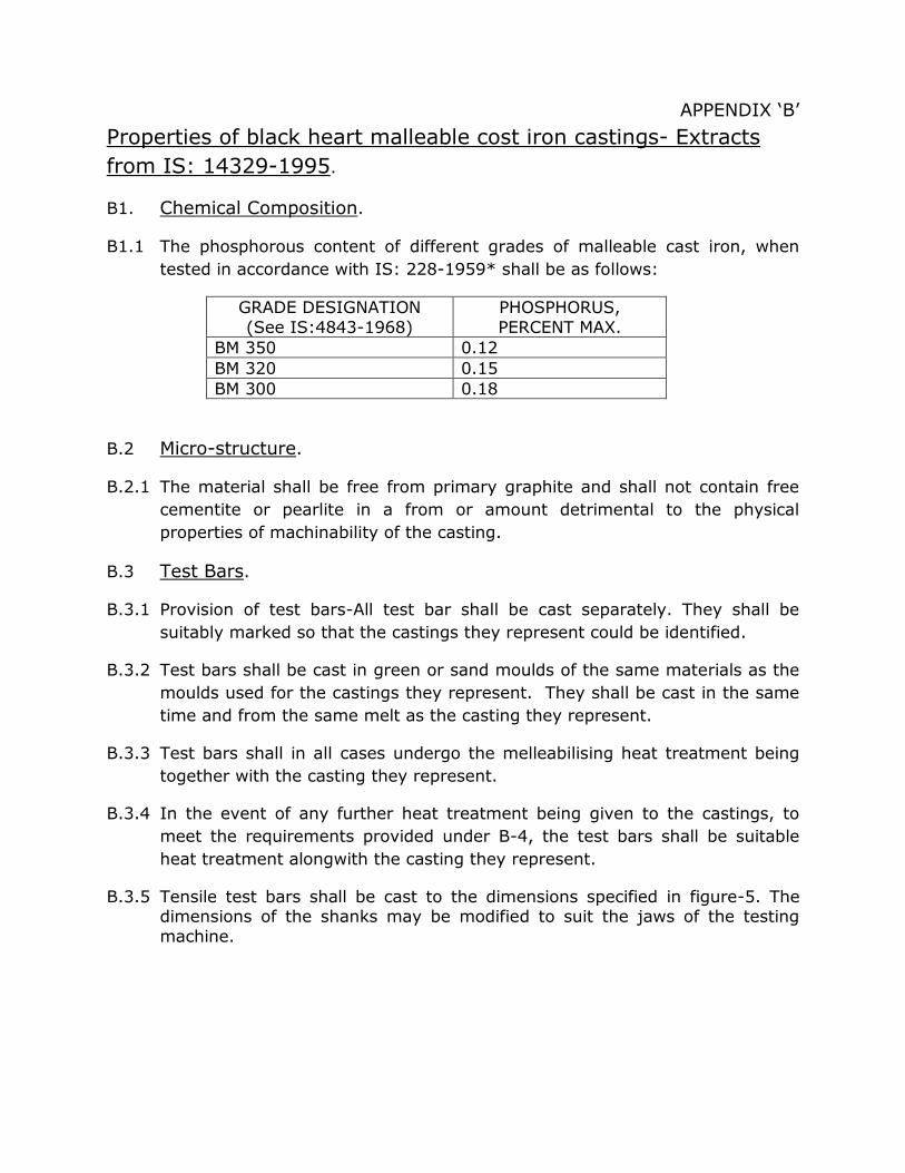
B.3.5 Tensile test bars shall be cast to the dimensions specified in figure-5. The dimensions of the shanks may be modified to suit the jaws of the testing
machine.
B.3.6 The cast tensile test bars may be dressed or cleaned and shall be tested in the un-machined condition.
B.4 Mechanical tests:
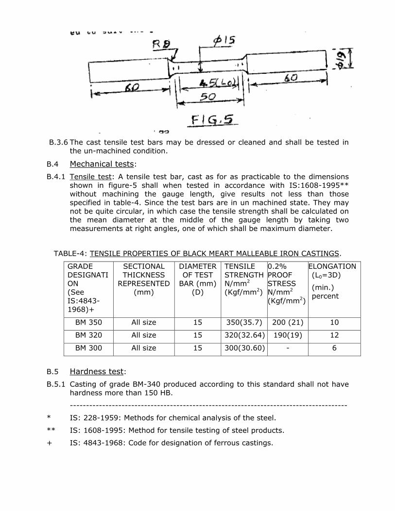
B.4.1 Tensile test: A tensile test bar, cast as for as practicable to the dimensions
shown in figure-5 shall when tested in accordance with IS:1608-1995** without machining the gauge length, give results not less than those
specified in table-4. Since the test bars are in un machined state. They may not be quite circular, in which case the tensile strength shall be calculated on the mean diameter at the middle of the gauge length by taking two
measurements at right angles, one of which shall be maximum diameter.
TABLE-4: TENSILE PROPERTIES OF BLACK MEART MALLEABLE IRON CASTINGS.
GRADE
DESIGNATION (See
IS:4843- 1968)+
SECTIONAL
THICKNESS REPRESENTED
(mm)
DIAMETER
OF TEST BAR (mm)
(D)
TENSILE
STRENGTH N/mm2
(Kgf/mm2)
0.2%
PROOF STRESS N/mm2
(Kgf/mm2)
ELONGATION
(L0=3D)
(min.) percent
BM 350 All size 15 350(35.7) 200 (21) 10
BM 320 All size 15 320(32.64) 190(19) 12
BM 300 All size 15 300(30.60) - 6
B.5 Hardness test:
B.5.1 Casting of grade BM-340 produced according to this standard shall not have hardness more than 150 HB.
--------------------------------------------------------------------------------------
* IS: 228-1959: Methods for chemical analysis of the steel.
** IS: 1608-1995: Method for tensile testing of steel products.
+ IS: 4843-1968: Code for designation of ferrous castings.
APPENDIX- ‘C’
Properties of tin bronze ingots and Castings – Extracts from
IS:306-1983.
C-1. Chemical composition:
C-1.1. The material when analysed either by the method specified in IS: 4027-
1967+ or any other instrumental/chemical method shall have the chemical
composition as given in Table-5:
TABLE-5: CHEMICAL COMPOSITION
* If specifically required by the purchaser, the material may be supplied with
restricted lead content.
C.1.2 The manufacturer shall, when required, supply free of charge, a copy of his
works analysis of the material. The works analysis is defined as the routine
analysis carried out by the manufacturer in order to control the quality of the
material.
C.2. Mechanical Properties:
C-2.1 The material when tested in accordance with IS: 2654-1977++ shall have
the mechanical properties as given in Table-6.
CONSTITUENTS PERCENT (castings)
Tin 9.5-10.5
Zinc 1.5-3.0
*Lead, Max. 1.5
Nickel, Max. 1.0
Iron, Max. 0.15
Aluminium, Max. 0.01
Silicon, Max. 0.02
Bismuth. Max. 0.03
Total impurity Max.(include iron,
Aluminium,Arsenic,Antimony,Silicon,Bismuth)
0.50
Copper Remainder
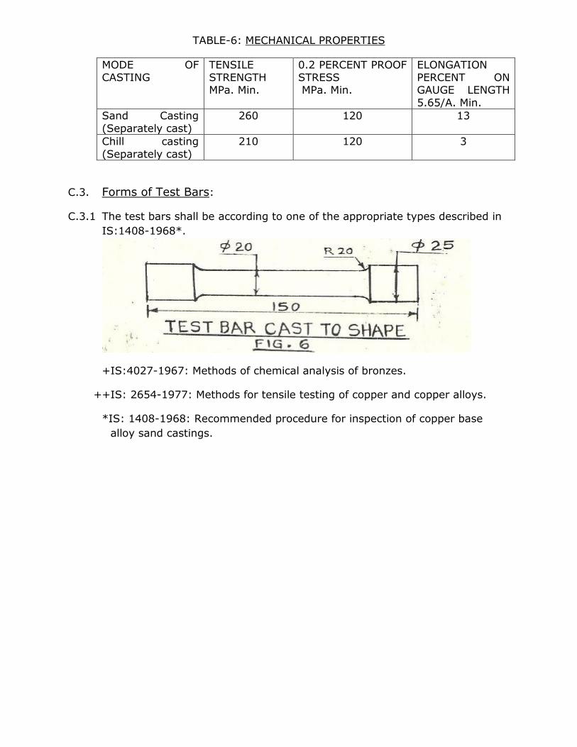
TABLE-6: MECHANICAL PROPERTIES
MODE OF CASTING
TENSILE STRENGTH MPa. Min.
0.2 PERCENT PROOF STRESS MPa. Min.
ELONGATION PERCENT ON GAUGE LENGTH
5.65/A. Min.
Sand Casting
(Separately cast)
260 120 13
Chill casting
(Separately cast)
210 120 3
C.3. Forms of Test Bars:
C.3.1 The test bars shall be according to one of the appropriate types described in
IS:1408-1968*.
+IS:4027-1967: Methods of chemical analysis of bronzes.
++IS: 2654-1977: Methods for tensile testing of copper and copper alloys.
*IS: 1408-1968: Recommended procedure for inspection of copper base
alloy sand castings.
APPENDIX-D
Aluminium and Aluminium Alloy Castings-Extracts from
IS: 617-1994.
D-1 Chemical Composition and Mechanical Properties.
D-1.1 The Chemical Composition and Mechanical properties of Aluminium and
Aluminium alloy are given in Table-7. The Mechanical properties given in
Table-6 apply to separately cast test piece. The Chemical Composition of
Aluminium alloy fittings/ test bars shall be tested in accordance with IS:504-
1963.*
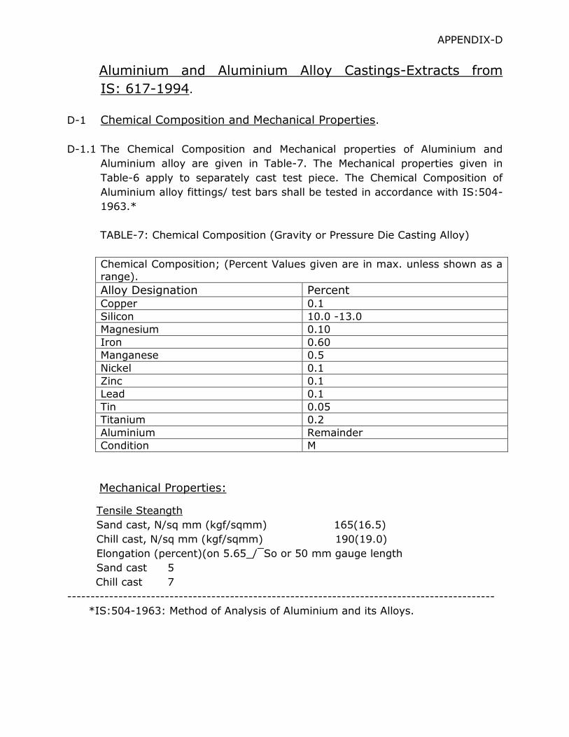
TABLE-7: Chemical Composition (Gravity or Pressure Die Casting Alloy)
Chemical Composition; (Percent Values given are in max. unless shown as a
range).
Alloy Designation Percent Copper 0.1
Silicon 10.0 -13.0
Magnesium 0.10
Iron 0.60
Manganese 0.5
Nickel 0.1
Zinc 0.1
Lead 0.1
Tin 0.05
Titanium 0.2
Aluminium Remainder
Condition M
Mechanical Properties:
Tensile Steangth
Sand cast, N/sq mm (kgf/sqmm) 165(16.5)
Chill cast, N/sq mm (kgf/sqmm) 190(19.0)
Elongation (percent)(on 5.65_/¯So or 50 mm gauge length
Sand cast 5
Chill cast 7
--------------------------------------------------------------------------------------------
*IS:504-1963: Method of Analysis of Aluminium and its Alloys.
D-2 Sample for Mechanical Tests of Castings.
D-2.1 The metal for the test sample shall be taken from the crucible or ladle from
which, the castings are poured and shall not be subjected to any further
treatment other than adjustment of the temperature to that suitable for
pouring.
D-2.1.1Sand Casting: The test samples shall be cast in dry sand moulds which shall
have internal dimensions as shown in figure-1 or 2 of IS:617-1994. The
moulds shall be inclined from the vertical at the commencement of pouring
and the metal shall be poured into the top of the moulds. The sand of the
moulds may be rammed into any convenient container (such as steel tube),
provide that the portion of the bar tapering from 25 to 24 mm is separated
from the container walls by not less than 27 mm of sand.
D-3 Tests for physical Properties.
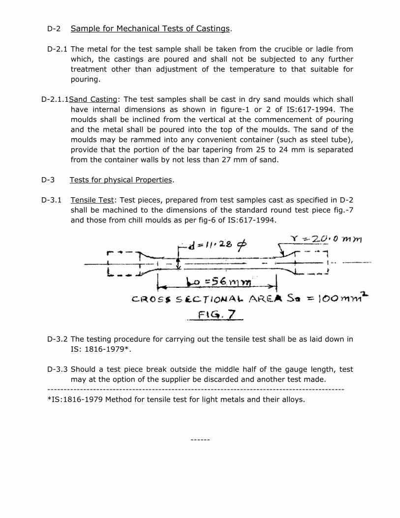
D-3.1 Tensile Test: Test pieces, prepared from test samples cast as specified in D-2
shall be machined to the dimensions of the standard round test piece fig.-7
and those from chill moulds as per fig-6 of IS:617-1994.
D-3.2 The testing procedure for carrying out the tensile test shall be as laid down in
IS: 1816-1979*.
D-3.3 Should a test piece break outside the middle half of the gauge length, test
may at the option of the supplier be discarded and another test made.
-------------------------------------------------------------------------------------------
*IS:1816-1979 Method for tensile test for light metals and their alloys.
------
APPENDIX ‘E’
Forged Steel- Extract from IS: 2004-1991.
E-1 Chemical Composition
E-1.1Ladle Analysis- The analysis of the steel shall conform to the requirements
given in Table-8. The methods of chemical analysis shall be as prescribed
in the relevant part of IS: 228-1959.
TABLE-8: CHEMICAL COMPOSITION
----------------------------------------------------------------------------------
CLASS
DESIGNATION IS:1762 (Pt-1) -1974*
CONSTITUENT, Percent
Carbon Silicon Manganese Sulphur
Max.
Phosphorus
Max.
1 14 C6 0.10 to
0.18
0.15 to
0.35
0.40 to
0.70
0.040 0.040
1A 15 C8 0.10 to
0.20
0.15 to
0.35
0.60 to
0.90
0.040 0.040
2 20 C8 0.15 to
0.25
0.15 to
0.35
0.60 to
0.90
0.040 0.040
2A 25 C8 0.20 to
0.30
0.15 to
0.35
0.60 to
0.90
0.040 0.040
3 30 C8 0.25 to
0.35
0.15 to
0.35
0.60 to
0.90
0.040 0.040
3A 35 C8 0.30 to
0.40
0.15 to
0.35
0.60 to
0.90
0.040 0.040
4 45 C8 0.40 to
0.50
0.15 to
0.35
0.60 to
0.90
0.040 0.040
5 55 C8 0.50 to
0.60
0.15 to
0.35
0.060 to
0.90
0.040 0.040
6 65 C6 0.60 to
0.70
0.15 to
0.35
0.50 to
0.80
0.040 0.040
Note(1): When the steel is Aluminium killed or killed or killed with both
Aluminium and Silicon, the requirement of minimum Silicon content
shall not apply. For Aluminium killed steel the total Aluminium content
shall be within 0.02 to 0.05 percent.
*IS: 1762 (Pt-I)- 1974: Code for designation of Steels- based on the letter
Symbols.
aIS:228: Method for Chemical Analysis of steel.
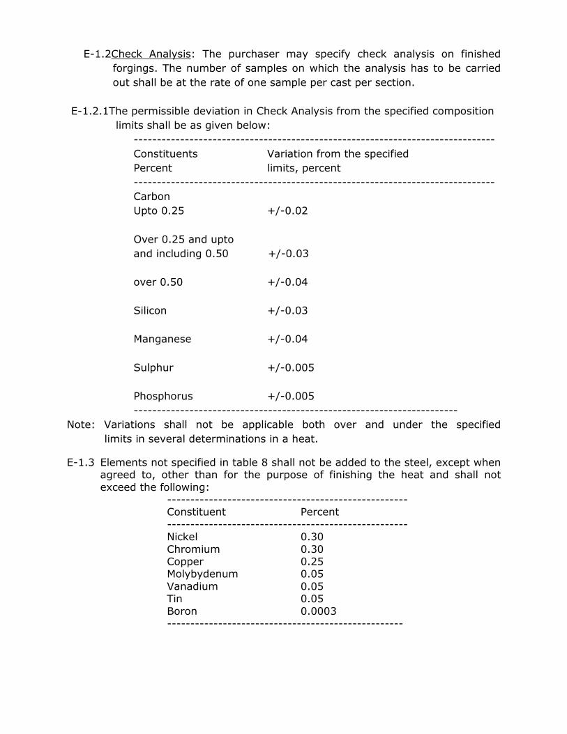
E-1.2Check Analysis: The purchaser may specify check analysis on finished
forgings. The number of samples on which the analysis has to be carried
out shall be at the rate of one sample per cast per section.
E-1.2.1The permissible deviation in Check Analysis from the specified composition
limits shall be as given below:
------------------------------------------------------------------------------
Constituents Variation from the specified
Percent limits, percent
------------------------------------------------------------------------------
Carbon
Upto 0.25 +/-0.02
Over 0.25 and upto
and including 0.50 +/-0.03
over 0.50 +/-0.04
Silicon +/-0.03
Manganese +/-0.04
Sulphur +/-0.005
Phosphorus +/-0.005
----------------------------------------------------------------------
Note: Variations shall not be applicable both over and under the specified
limits in several determinations in a heat.
E-1.3 Elements not specified in table 8 shall not be added to the steel, except when agreed to, other than for the purpose of finishing the heat and shall not
exceed the following: ---------------------------------------------------- Constituent Percent
---------------------------------------------------- Nickel 0.30
Chromium 0.30 Copper 0.25 Molybydenum 0.05
Vanadium 0.05 Tin 0.05
Boron 0.0003 ---------------------------------------------------
E-2 Mechanical Test:
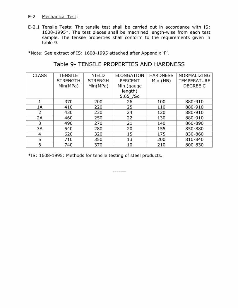
E-2.1 Tensile Tests: The tensile test shall be carried out in accordance with IS: 1608-1995*. The test pieces shall be machined length-wise from each test
sample. The tensile properties shall conform to the requirements given in table 9.
*Note: See extract of IS: 1608-1995 attached after Appendix ‘F’.
Table 9- TENSILE PROPERTIES AND HARDNESS
CLASS TENSILE STRENGTH
Min(MPa)
YIELD STRENGH
Min(MPa)
ELONGATION PERCENT
Min.(gauge length)
5.65_/So
HARDNESS Min.(HB)
NORMALIZING TEMPERATURE
DEGREE C
1 370 200 26 100 880-910
1A 410 220 25 110 880-910
2 430 230 24 120 880-910
2A 460 250 22 130 880-910
3 490 270 21 140 860-890
3A 540 280 20 155 850-880
4 620 320 15 175 830-860
5 710 350 13 200 810-840
6 740 370 10 210 800-830
*IS: 1608-1995: Methods for tensile testing of steel products.
-------
APPENDIX ‘F’
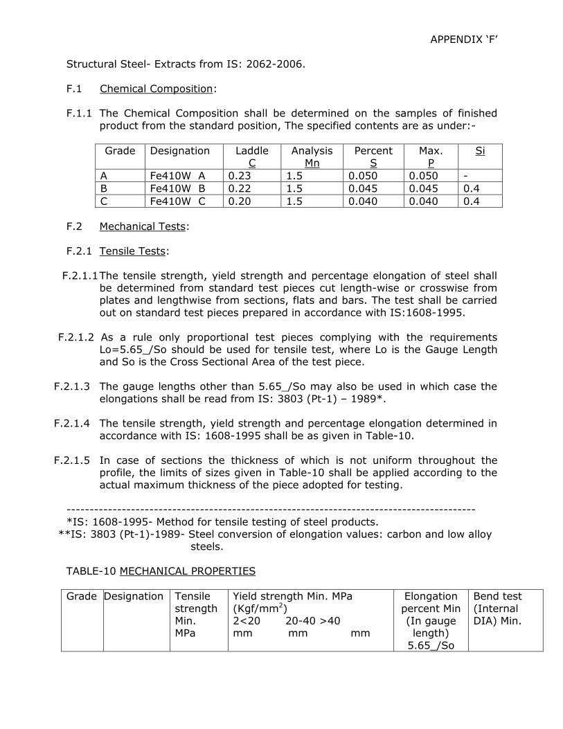
Structural Steel- Extracts from IS: 2062-2006.
F.1 Chemical Composition: F.1.1 The Chemical Composition shall be determined on the samples of finished
product from the standard position, The specified contents are as under:-
Grade Designation Laddle C
Analysis Mn
Percent S
Max. P
Si
A Fe410W A 0.23 1.5 0.050 0.050 -
B Fe410W B 0.22 1.5 0.045 0.045 0.4
C Fe410W C 0.20 1.5 0.040 0.040 0.4
F.2 Mechanical Tests:
F.2.1 Tensile Tests:
F.2.1.1 The tensile strength, yield strength and percentage elongation of steel shall be determined from standard test pieces cut length-wise or crosswise from plates and lengthwise from sections, flats and bars. The test shall be carried
out on standard test pieces prepared in accordance with IS:1608-1995.
F.2.1.2 As a rule only proportional test pieces complying with the requirements Lo=5.65_/So should be used for tensile test, where Lo is the Gauge Length and So is the Cross Sectional Area of the test piece.
F.2.1.3 The gauge lengths other than 5.65_/So may also be used in which case the
elongations shall be read from IS: 3803 (Pt-1) – 1989*.
F.2.1.4 The tensile strength, yield strength and percentage elongation determined in
accordance with IS: 1608-1995 shall be as given in Table-10.
F.2.1.5 In case of sections the thickness of which is not uniform throughout the profile, the limits of sizes given in Table-10 shall be applied according to the actual maximum thickness of the piece adopted for testing.
-----------------------------------------------------------------------------------------
*IS: 1608-1995- Method for tensile testing of steel products. **IS: 3803 (Pt-1)-1989- Steel conversion of elongation values: carbon and low alloy
steels.
TABLE-10 MECHANICAL PROPERTIES
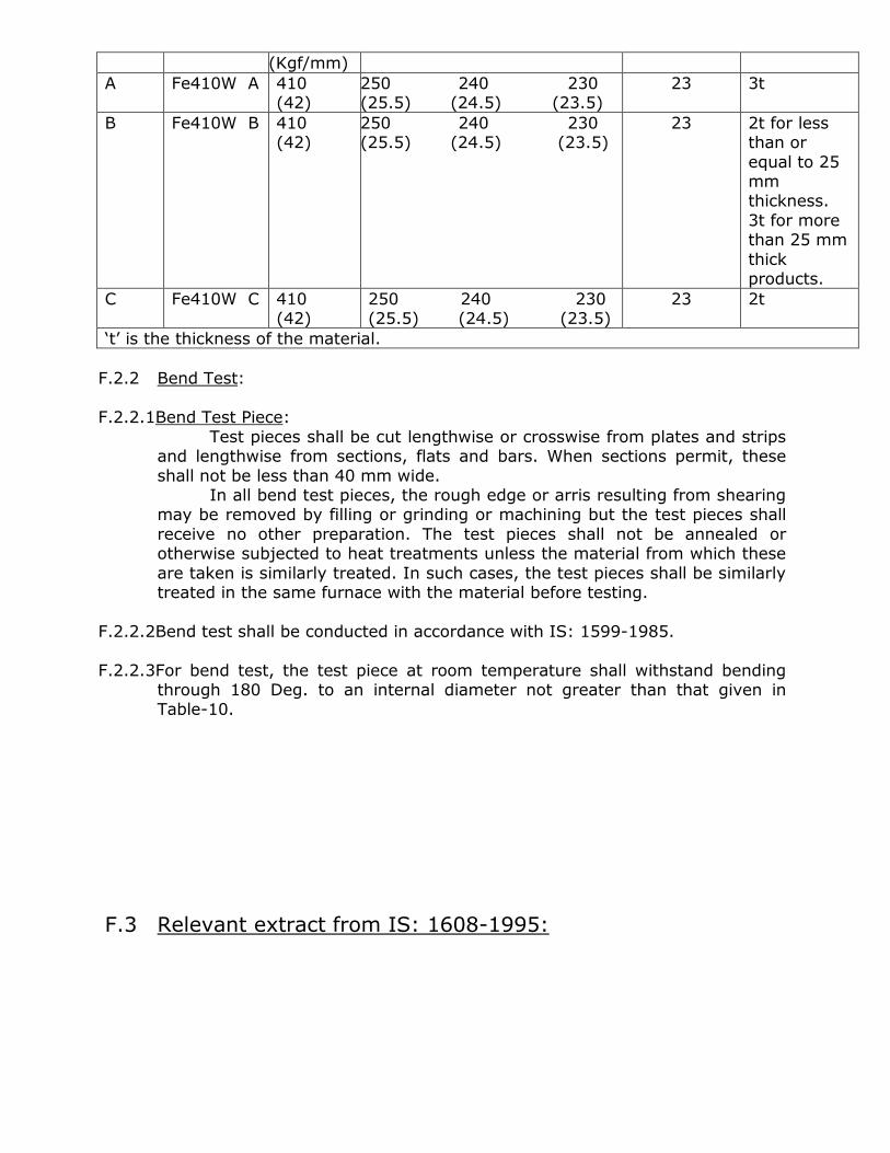
Grade Designation Tensile
strength Min. MPa
Yield strength Min. MPa
(Kgf/mm2) 2<20 20-40 >40 mm mm mm
Elongation
percent Min (In gauge length)
5.65_/So
Bend test
(Internal DIA) Min.
(Kgf/mm)
A Fe410W A 410 (42)
250 240 230 (25.5) (24.5) (23.5)
23 3t
B Fe410W B 410 (42)
250 240 230 (25.5) (24.5) (23.5)
23 2t for less than or
equal to 25 mm thickness.
3t for more than 25 mm
thick products.
C Fe410W C 410 (42)
250 240 230 (25.5) (24.5) (23.5)
23 2t
‘t’ is the thickness of the material.
F.2.2 Bend Test:
F.2.2.1Bend Test Piece:
Test pieces shall be cut lengthwise or crosswise from plates and strips and lengthwise from sections, flats and bars. When sections permit, these
shall not be less than 40 mm wide. In all bend test pieces, the rough edge or arris resulting from shearing
may be removed by filling or grinding or machining but the test pieces shall
receive no other preparation. The test pieces shall not be annealed or otherwise subjected to heat treatments unless the material from which these
are taken is similarly treated. In such cases, the test pieces shall be similarly treated in the same furnace with the material before testing.
F.2.2.2Bend test shall be conducted in accordance with IS: 1599-1985.
F.2.2.3For bend test, the test piece at room temperature shall withstand bending through 180 Deg. to an internal diameter not greater than that given in Table-10.
F.3 Relevant extract from IS: 1608-1995:
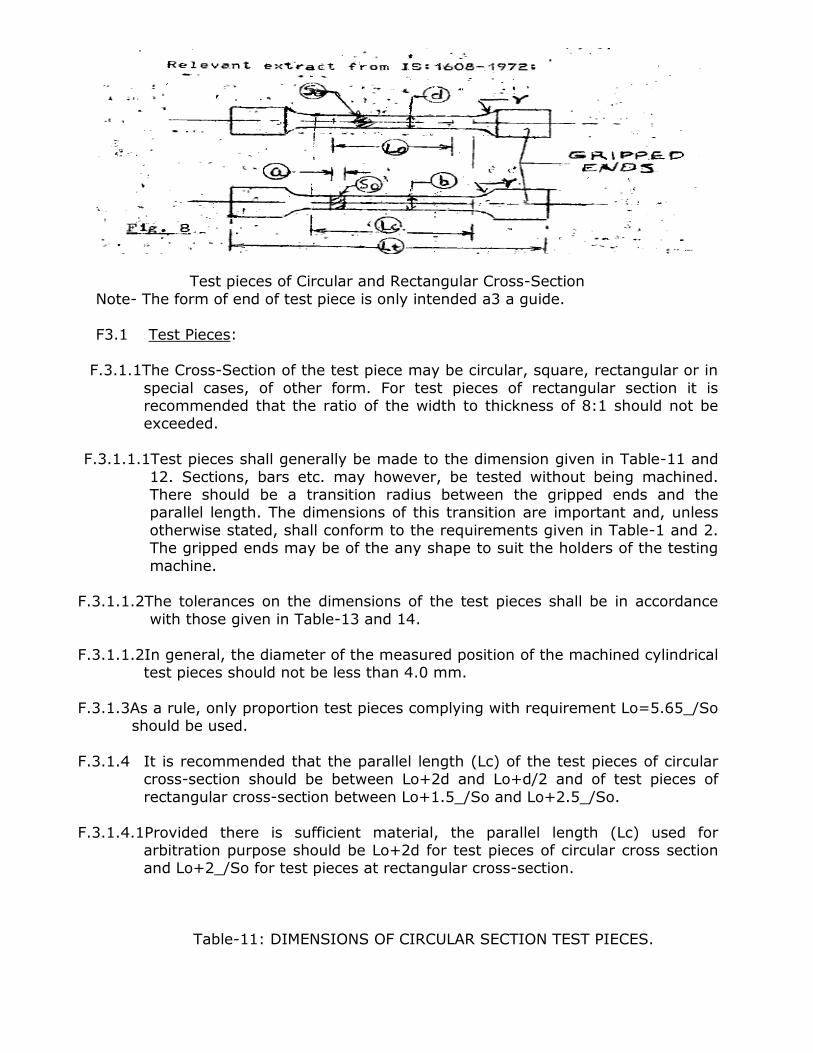
Test pieces of Circular and Rectangular Cross-Section
Note- The form of end of test piece is only intended a3 a guide. F3.1 Test Pieces:
F.3.1.1The Cross-Section of the test piece may be circular, square, rectangular or in
special cases, of other form. For test pieces of rectangular section it is recommended that the ratio of the width to thickness of 8:1 should not be exceeded.
F.3.1.1.1Test pieces shall generally be made to the dimension given in Table-11 and
12. Sections, bars etc. may however, be tested without being machined. There should be a transition radius between the gripped ends and the parallel length. The dimensions of this transition are important and, unless
otherwise stated, shall conform to the requirements given in Table-1 and 2. The gripped ends may be of the any shape to suit the holders of the testing
machine.
F.3.1.1.2The tolerances on the dimensions of the test pieces shall be in accordance
with those given in Table-13 and 14.
F.3.1.1.2In general, the diameter of the measured position of the machined cylindrical test pieces should not be less than 4.0 mm.
F.3.1.3As a rule, only proportion test pieces complying with requirement Lo=5.65_/So should be used.
F.3.1.4 It is recommended that the parallel length (Lc) of the test pieces of circular
cross-section should be between Lo+2d and Lo+d/2 and of test pieces of
rectangular cross-section between Lo+1.5_/So and Lo+2.5_/So.
F.3.1.4.1Provided there is sufficient material, the parallel length (Lc) used for arbitration purpose should be Lo+2d for test pieces of circular cross section and Lo+2_/So for test pieces at rectangular cross-section.
Table-11: DIMENSIONS OF CIRCULAR SECTION TEST PIECES.

(Clause 5.1.1) Gauge length Lo=5.65_/So
Cross Sectional
Area Sqmm
Diameter d
Mm
Gauge length diameter
Lo mm
Minimum parallel
length Lc=5.5 d
Minimum transition
radius r mm
400 22.56 113 124 23.5
200 15.96 80 88 15
150 13.82 69 76 10
100 11.28 56 62 10
50 7.89 40 44 8
25 5.84 28 31 5
12.2 3.99 20 22 4
Note-1:The gauge length is given to the nearest 1 mm and the minimum parallel
length is adjusted accordingly. Note-2:Test pieces with diameters other than these given in this table may be used
provided that the gauge length Lo=5.65_/So.
Table 12: DIMENSIONS OF RECTANGULAR SECTION TEST PIECES (NON-PROPORTIONAL) (CLAUSE 5.1.1)
All dimensions in mm.
WIDTH b
GAUGE LENGTH Lo
MINIMUM TRANSITION
RADIUS r
APPROXIMATE TOTAL
LENGTH Lt
40 200 25 450
20 200 25 375
25 100 25 300
12.5 50 25 200
6 24 12 100
3 12 6 50
Note-1:Not withstanding the above, test pieces having a gauge length equal to 5.65
So are permitted. Note-2:For any width from 3 to 25 mm a gauge length of 50 mm may be used, the
total length being adjusted accordingly.
Note-3:A straight, parallel test piece without enlarged ends is permissible for any size.
Table-13:TOLERANCE ON DIMENSIONS OF CIRCULAR CROSS-SECTION TEST PIECES (CLAUSE 5.1.2)
(All dimensions in mm.)
Nominal dimensions Machining tolerance* on
nominal dimensions
Tolerance on form
4 to 6 +/- 0.06 0.03
Over 6 to 10 +/- 0.075 0.04
Over 10 to 18 +/- 0.09 0.04
Over 18 to 30 +/- 0.105 0.05
* The machining tolerance applies when it is desired to use the nominal cross-section without measurement or calculation.
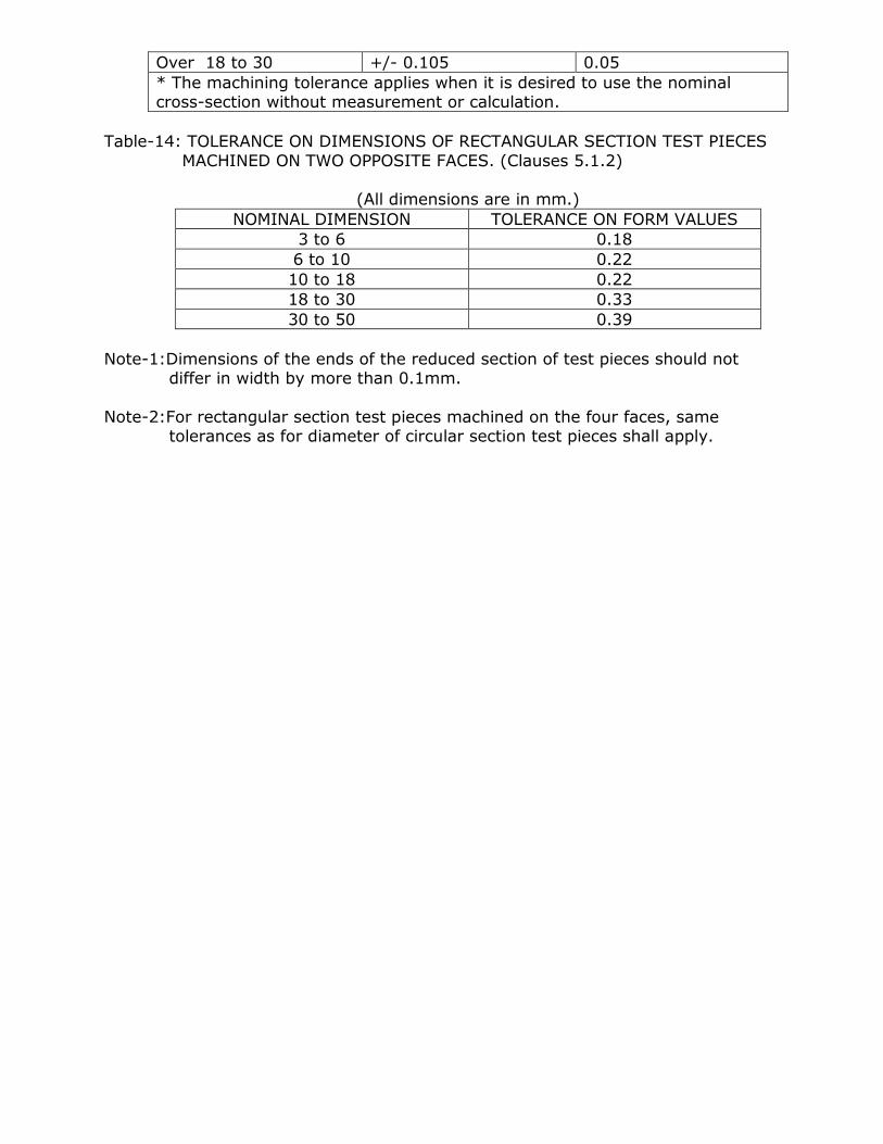
Table-14: TOLERANCE ON DIMENSIONS OF RECTANGULAR SECTION TEST PIECES
MACHINED ON TWO OPPOSITE FACES. (Clauses 5.1.2)
(All dimensions are in mm.)
NOMINAL DIMENSION TOLERANCE ON FORM VALUES
3 to 6 0.18
6 to 10 0.22
10 to 18 0.22
18 to 30 0.33
30 to 50 0.39
Note-1:Dimensions of the ends of the reduced section of test pieces should not differ in width by more than 0.1mm.
Note-2:For rectangular section test pieces machined on the four faces, same
tolerances as for diameter of circular section test pieces shall apply.
APPENDIX-‘G’
COPPER STRIP FOR ELECTRICAL PURPOSES
(Extracts from IS: 1897-1983)
G.1 Chemical Composition.
G1.1.1The Chemical Composition shall be determined either by the method specified
in IS: 440-1964* or any other established Instrumental/Chemical Method. In
case of dispute the procedure specified in latest edition of IS: 440-1964* for
Chemical analysis shall be the reference method. The material shall conform
to grade ETP or FRHC of IS:191 (Pt-I to X)- 1980.**
G2. Physical Properties.
G.2.1 The material when tested in accordance with IS: 3260-1965# and IS: 2654-
1977+ shall have the Physical Properties as given in Clause 7.2 & 7.3
respectively.
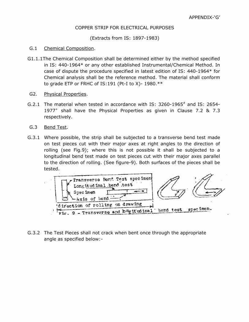
G.3 Bend Test.
G.3.1 Where possible, the strip shall be subjected to a transverse bend test made
on test pieces cut with their major axes at right angles to the direction of
rolling (see Fig.9); where this is not possible it shall be subjected to a
longitudinal bend test made on test pieces cut with their major axes parallel
to the direction of rolling. (See figure-9). Both surfaces of the pieces shall be
tested.
G.3.2 The Test Pieces shall not crack when bent once through the appropriate
angle as specified below:-

BEND TEST ------------------------------------------------------------------------------
Bend Test Thickness Condition Transverse or Longitudinal
Angle in Radius Degree -------------------------------------------------------------------------------
Upto and Annealed (0) 180 Close Including Half hard (HB) 180 t
10 mm Hard (HD) 90 t t=thickness of material
------------------------------------------------------------------------------- G.3.3 The Test pieces shall be of conventent length and the width shall be as
follows:
Thickness Width Upto and including 6.0 mm 15 mm where possible, otherwise full
Width.
Over 6.0 mm 2 times the thickness of material.
G.3.4 The longer edges shall be carefully rounded and smoothened longitudinally
so that the cross. Section has approximately semi-circular edges.
G.4 Tensile Test.
G.4.1 Material of thickness 0.50 m and upto and including 10 mm shall comply with
the requirements of Tensile Test given in Table-15. Material below 0.50 mm
thick shall not be subjected to Tensile Test.
G.4.2 Test pieces of full thickness of the material with a gauge length 4_/Area or
50 mm shall be used. The longitudinal axis of the test piece shall be in the
direction of rolling.
TABLE-15: TENSILE PROPERTIES OF STRIP --------------------------------------------------------------------------------------
Upto and including Over 300 mm upto
300 mm width and including Thickness Temper 1000 mm width
---------------- ------------------------------------------------------------- Over Upto & Tensile Elongation Tensile Elongation mm including strength percent on strength percent on
mm kgf/sqmm 4_/Area Kgf/sqmm 4_/Area (Min.) or 50 mm (Min.) gauge
Gauge length Length(Min.) (Min.)
-------------------------------------------------------------------------------------- i) 0.50 2.50 Annealed (O) 21.0 35.0 21.0 35.0 Half hard (HB) 25.0 10.0 25.0 10.0
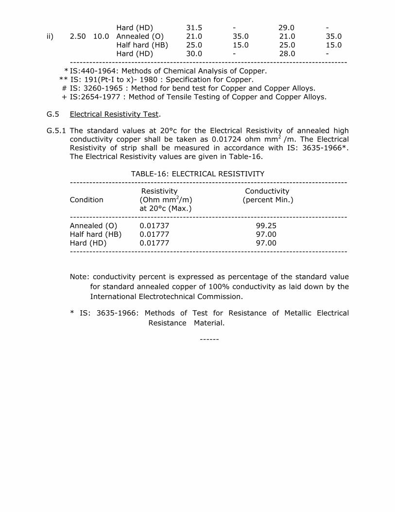
Hard (HD) 31.5 - 29.0 - ii) 2.50 10.0 Annealed (O) 21.0 35.0 21.0 35.0
Half hard (HB) 25.0 15.0 25.0 15.0 Hard (HD) 30.0 - 28.0 -
-------------------------------------------------------------------------------------- * IS:440-1964: Methods of Chemical Analysis of Copper. ** IS: 191(Pt-I to x)- 1980 : Specification for Copper.
# IS: 3260-1965 : Method for bend test for Copper and Copper Alloys. + IS:2654-1977 : Method of Tensile Testing of Copper and Copper Alloys.
G.5 Electrical Resistivity Test.
G.5.1 The standard values at 20°c for the Electrical Resistivity of annealed high conductivity copper shall be taken as 0.01724 ohm mm2 /m. The Electrical Resistivity of strip shall be measured in accordance with IS: 3635-1966*.
The Electrical Resistivity values are given in Table-16.
TABLE-16: ELECTRICAL RESISTIVITY -------------------------------------------------------------------------------------- Resistivity Conductivity
Condition (Ohm mm2/m) (percent Min.) at 20°c (Max.)
-------------------------------------------------------------------------------------- Annealed (O) 0.01737 99.25 Half hard (HB) 0.01777 97.00
Hard (HD) 0.01777 97.00 --------------------------------------------------------------------------------------
Note: conductivity percent is expressed as percentage of the standard value
for standard annealed copper of 100% conductivity as laid down by the
International Electrotechnical Commission.
* IS: 3635-1966: Methods of Test for Resistance of Metallic Electrical
Resistance Material.
------

APPENDIX-‘H’
Properties of wrought Aluminium and Aluminium Alloys, sheet & strip- Extract
from IS: 737-1986
H.1 Chemical Composition.
H.1.1 The Chemical Composition and Mechanical properties of wrought Aluminium
and Aluminium Alloys, sheet and strip are given in Table- 17. Chemical
analysis shall be carried out in accordance with IS: 504-1963*.
TABLE-17: CHEMICAL COMPOSITION AND MECHANICAL PROPERTIES.
--------------------------------------------------------------------------------------------- A. Chemical composition: (Values given are in percent,
Maximum unless shown otherwise)
Alloy Designation – 52000, Condition – H2 Copper 0.1 Chromium 0.25
Magnesium 0.7 to 2.6 Titanium and/or Silicon 0.6 other grain
Iron 0.7 refining Manganese 0.5 elements 0.2 Zinc 0.2 Aluminium Remainder
Remarks : Chromium + Manganese 0.5
B. Mechanical Properties: i) Tensile Strength, MPa (Kgf/mm2 ) 230 to 275
(23.5 to 28.00)
ii) Elongation on 50 mm gauge 4 length, min. in percent for thickness over 2.6 to 6.3 mm.
iii) 0.2% proof stress (min) 17.5
MPa (kgf/sqmm) (18) --------------------------------------------------------------------------------------------- H.2 Mechanical Test:
H.2.1 Tensile Test and proof stress- Tensile test shall be carried out and proof
stress determined thereby in accordance with aIS: 1816-1979. The values
obtained shall comply with the requirements given in Table-17.
H.2.1.1The Tensile Test piece shall be of rectangular section and having the
dimension as given in aIS: 1816-1979 with a gauge length of 50 mm. The
test piece shall be cut transverse to the direction of rolling for sheet and
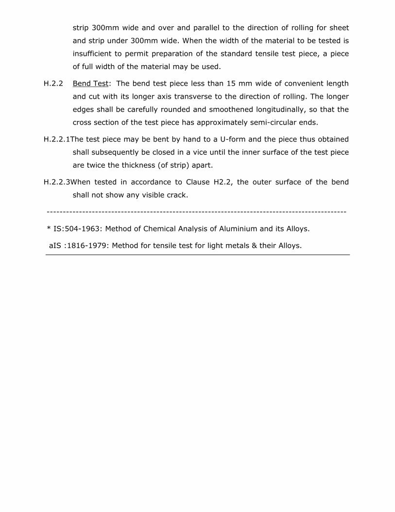
strip 300mm wide and over and parallel to the direction of rolling for sheet
and strip under 300mm wide. When the width of the material to be tested is
insufficient to permit preparation of the standard tensile test piece, a piece
of full width of the material may be used.
H.2.2 Bend Test: The bend test piece less than 15 mm wide of convenient length
and cut with its longer axis transverse to the direction of rolling. The longer
edges shall be carefully rounded and smoothened longitudinally, so that the
cross section of the test piece has approximately semi-circular ends.
H.2.2.1The test piece may be bent by hand to a U-form and the piece thus obtained
shall subsequently be closed in a vice until the inner surface of the test piece
are twice the thickness (of strip) apart.
H.2.2.3When tested in accordance to Clause H2.2, the outer surface of the bend
shall not show any visible crack.
---------------------------------------------------------------------------------------------
* IS:504-1963: Method of Chemical Analysis of Aluminium and its Alloys.
aIS :1816-1979: Method for tensile test for light metals & their Alloys.
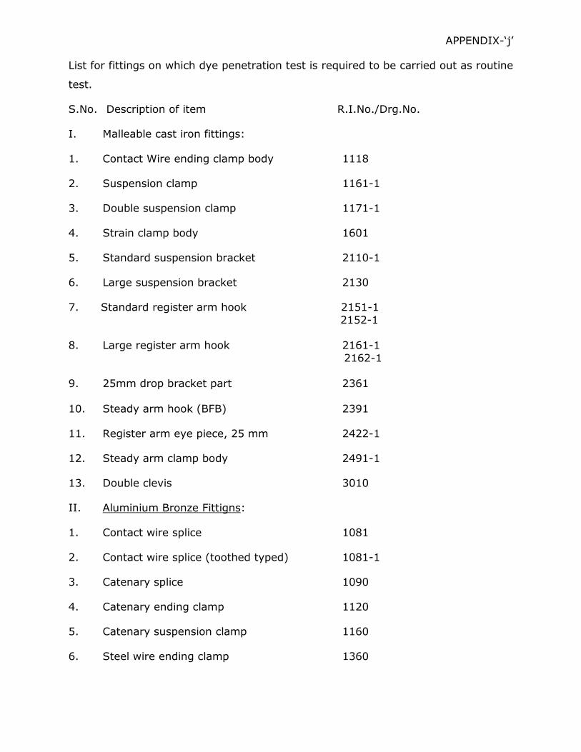
APPENDIX-‘j’
List for fittings on which dye penetration test is required to be carried out as routine
test.
S.No. Description of item R.I.No./Drg.No.
I. Malleable cast iron fittings:
1. Contact Wire ending clamp body 1118
2. Suspension clamp 1161-1
3. Double suspension clamp 1171-1
4. Strain clamp body 1601
5. Standard suspension bracket 2110-1
6. Large suspension bracket 2130
7. Standard register arm hook 2151-1
2152-1 8. Large register arm hook 2161-1
2162-1
9. 25mm drop bracket part 2361 10. Steady arm hook (BFB) 2391
11. Register arm eye piece, 25 mm 2422-1
12. Steady arm clamp body 2491-1
13. Double clevis 3010
II. Aluminium Bronze Fittigns:
1. Contact wire splice 1081
2. Contact wire splice (toothed typed) 1081-1
3. Catenary splice 1090
4. Catenary ending clamp 1120
5. Catenary suspension clamp 1160
6. Steel wire ending clamp 1360
7. Standard catenary suspension bracket 2110
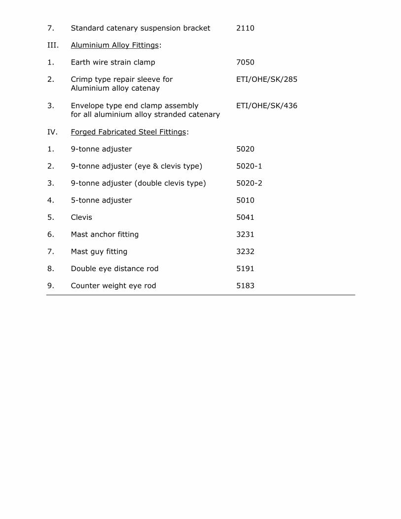
III. Aluminium Alloy Fittings:
1. Earth wire strain clamp 7050
2. Crimp type repair sleeve for ETI/OHE/SK/285
Aluminium alloy catenay
3. Envelope type end clamp assembly ETI/OHE/SK/436 for all aluminium alloy stranded catenary
IV. Forged Fabricated Steel Fittings:
1. 9-tonne adjuster 5020
2. 9-tonne adjuster (eye & clevis type) 5020-1
3. 9-tonne adjuster (double clevis type) 5020-2
4. 5-tonne adjuster 5010
5. Clevis 5041
6. Mast anchor fitting 3231
7. Mast guy fitting 3232
8. Double eye distance rod 5191
9. Counter weight eye rod 5183
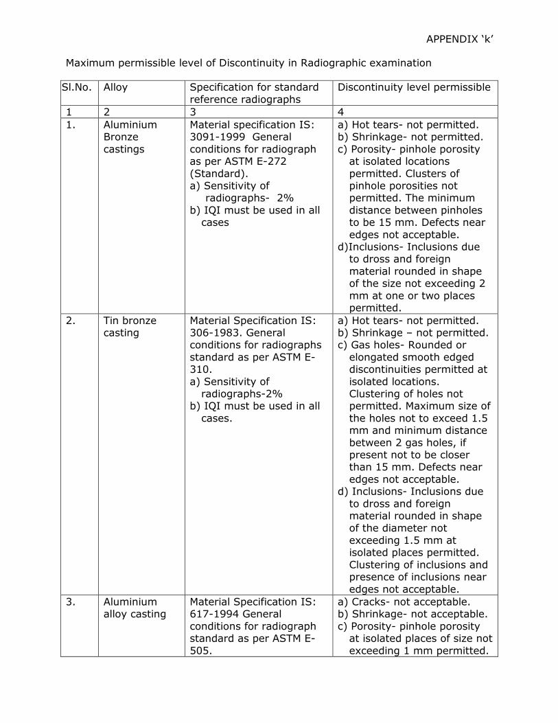
APPENDIX ‘k’
Maximum permissible level of Discontinuity in Radiographic examination
Sl.No. Alloy Specification for standard
reference radiographs
Discontinuity level permissible
1 2 3 4
1. Aluminium Bronze
castings
Material specification IS: 3091-1999 General
conditions for radiograph as per ASTM E-272
(Standard). a) Sensitivity of
radiographs- 2%
b) IQI must be used in all cases
a) Hot tears- not permitted. b) Shrinkage- not permitted.
c) Porosity- pinhole porosity at isolated locations
permitted. Clusters of pinhole porosities not permitted. The minimum
distance between pinholes to be 15 mm. Defects near
edges not acceptable. d)Inclusions- Inclusions due
to dross and foreign
material rounded in shape of the size not exceeding 2
mm at one or two places permitted.
2. Tin bronze casting
Material Specification IS: 306-1983. General conditions for radiographs
standard as per ASTM E-310.
a) Sensitivity of radiographs-2%
b) IQI must be used in all
cases.
a) Hot tears- not permitted. b) Shrinkage – not permitted. c) Gas holes- Rounded or
elongated smooth edged discontinuities permitted at
isolated locations. Clustering of holes not permitted. Maximum size of
the holes not to exceed 1.5 mm and minimum distance
between 2 gas holes, if present not to be closer than 15 mm. Defects near
edges not acceptable. d) Inclusions- Inclusions due
to dross and foreign material rounded in shape of the diameter not
exceeding 1.5 mm at isolated places permitted.
Clustering of inclusions and presence of inclusions near
edges not acceptable.
3. Aluminium alloy casting
Material Specification IS: 617-1994 General
conditions for radiograph standard as per ASTM E-
505.
a) Cracks- not acceptable. b) Shrinkage- not acceptable.
c) Porosity- pinhole porosity at isolated places of size not
exceeding 1 mm permitted.
a) Sensitivity of
radiographs- 2% b) IQI must be used in all
cases
Clusters of pinholes not
permitted. Presence of pin holes near edges not permitted.
d) Foreign material- Inclusions due to dross and
foreign material round in shape of the size not exceeding 1.5 mm at
isolated places permitted. Clustering of inclusions and
presence of inclusions near edges not permitted.
4. Malleable iron castings
Material specification IS:14329-1995 General condition for
radiograph standard- as per ASTM E-446
a) Radiograph sensitivity- 2% b) IQI must be used in all
cases.
a) Porosity- size of porosity of pin holes shall not be more than 1 mm in diameter and
the distance between two pin holes shall not be less
than 20 mm. Clustering of pin hoes shall not be permitted.
b) Slag inclusion – Slag inclusion of the size not
inclusion not more than 1 mm and the distance between slag inclusion
particles shall not be less than 20 mm. Clustering of
inclusion particles shall not be allowed.
c) Sand inclusion-do-
d) Hot tears- not permitted. e) Crack- not permitted.
f) Shrinkage- The total shrinkage area shall not
exceed 5% of the radiographic area.
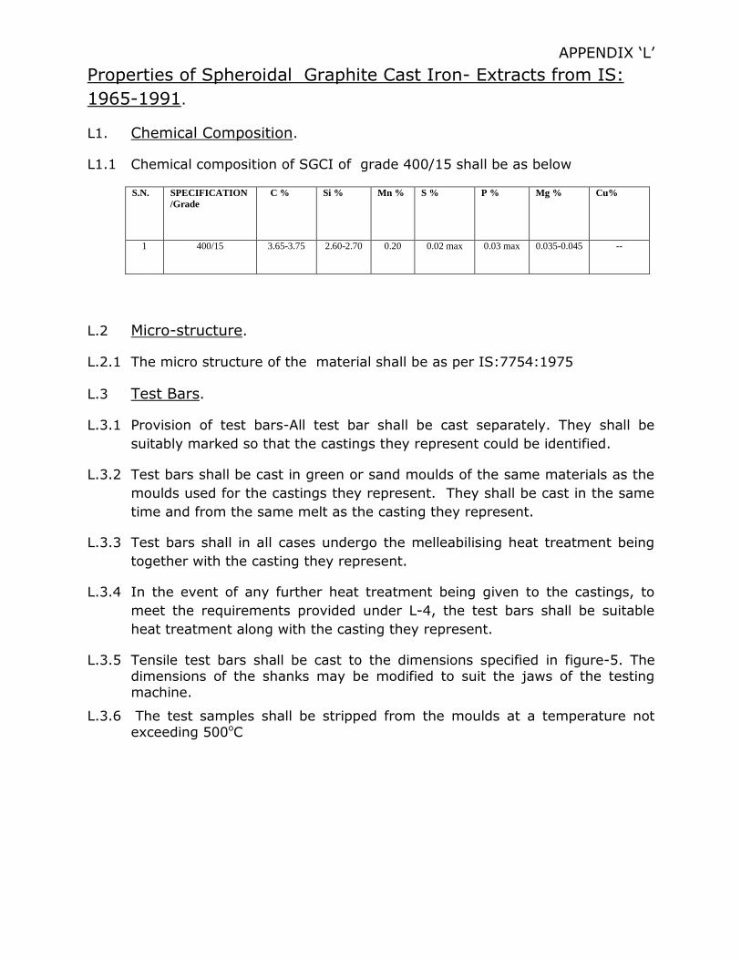
APPENDIX ‘L’
Properties of Spheroidal Graphite Cast Iron- Extracts from IS:
1965-1991.
L1. Chemical Composition.
L1.1 Chemical composition of SGCI of grade 400/15 shall be as below
S.N. SPECIFICATION
/Grade
C % Si % Mn % S % P % Mg % Cu%
1
400/15 3.65-3.75 2.60-2.70 0.20 0.02 max 0.03 max 0.035-0.045 --
L.2 Micro-structure.
L.2.1 The micro structure of the material shall be as per IS:7754:1975
L.3 Test Bars.
L.3.1 Provision of test bars-All test bar shall be cast separately. They shall be
suitably marked so that the castings they represent could be identified.
L.3.2 Test bars shall be cast in green or sand moulds of the same materials as the
moulds used for the castings they represent. They shall be cast in the same
time and from the same melt as the casting they represent.
L.3.3 Test bars shall in all cases undergo the melleabilising heat treatment being
together with the casting they represent.
L.3.4 In the event of any further heat treatment being given to the castings, to
meet the requirements provided under L-4, the test bars shall be suitable
heat treatment along with the casting they represent.
L.3.5 Tensile test bars shall be cast to the dimensions specified in figure-5. The dimensions of the shanks may be modified to suit the jaws of the testing machine.
L.3.6 The test samples shall be stripped from the moulds at a temperature not exceeding 500oC

L.3.6 The cast tensile test bars may be dressed or cleaned and shall be tested in the un-machined condition.
L.4 Mechanical tests:
L.4.1 Tensile test: A tensile test bar, cast as far as practicable to the dimensions
shown in figure-5 shall when tested in accordance with IS: 1608-1995** without machining the gauge length, give results not less than those
specified in table-4. Since the test bars are in Un- machined state. They may not be quite circular, in which case the tensile strength shall be calculated on the mean diameter at the middle of the gauge length by taking two
measurements at right angles, one of which shall be maximum diameter.
TABLE-4: TENSILE PROPERTIES OF BLACK MEART MALLEABLE IRON CASTINGS.
GRADE
DESIGNATION (See
IS:1965- 1991)+
SECTIONAL
THICKNESS REPRESENTED
(mm)
DIAMETER
OF TEST BAR (mm)
(D)
TENSILE
STRENGTH N/mm2
(Kgf/mm2)
0.2%
PROOF STRESS N/mm2
(Kgf/mm2)
ELONGATION
(L0=3D)
(min.) percent
SG 400 All size 15 400(40.8) 250 (25.5)
15
L.5 Hardness test:
L.5.1 Casting of grade SG-400 produced according to this standard shall have
hardness between 130-180 HB.
--------------------------------------------------------------------------------------
* IS: 228-1959: Methods for chemical analysis of the steel.
** IS: 1608-1995: Method for tensile testing of steel products.
+ IS: 4843-1968: Code for designation of ferrous castings.