Embed Size (px)
Citation preview
Section 7: PRISMATIC BEAMS
Global Stiffness Matrix For BeamsThe concept of an overall joint stiffness matrix will be explained in conjunction with the two span beam shown below. Here no loads are applied on the structure.
The restrained structure and the six possible joint displacements are labeled. Keep in mind that the axial stiffness is assumed to be large relative to flexural stiffness.
Section 7: PRISMATIC BEAMS
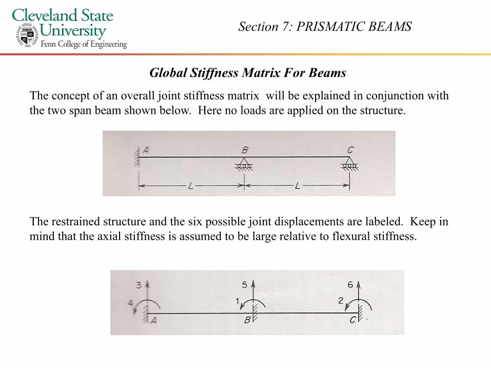
An overall stiffness matrix, [KJ ], can be generated that contains terms for all
ibl j i di l i l dipossible joint displacements, including those restrained at the supports. This matrix involves application of unit displacements as shown in the figures to p gthe right and below.
Section 7: PRISMATIC BEAMS
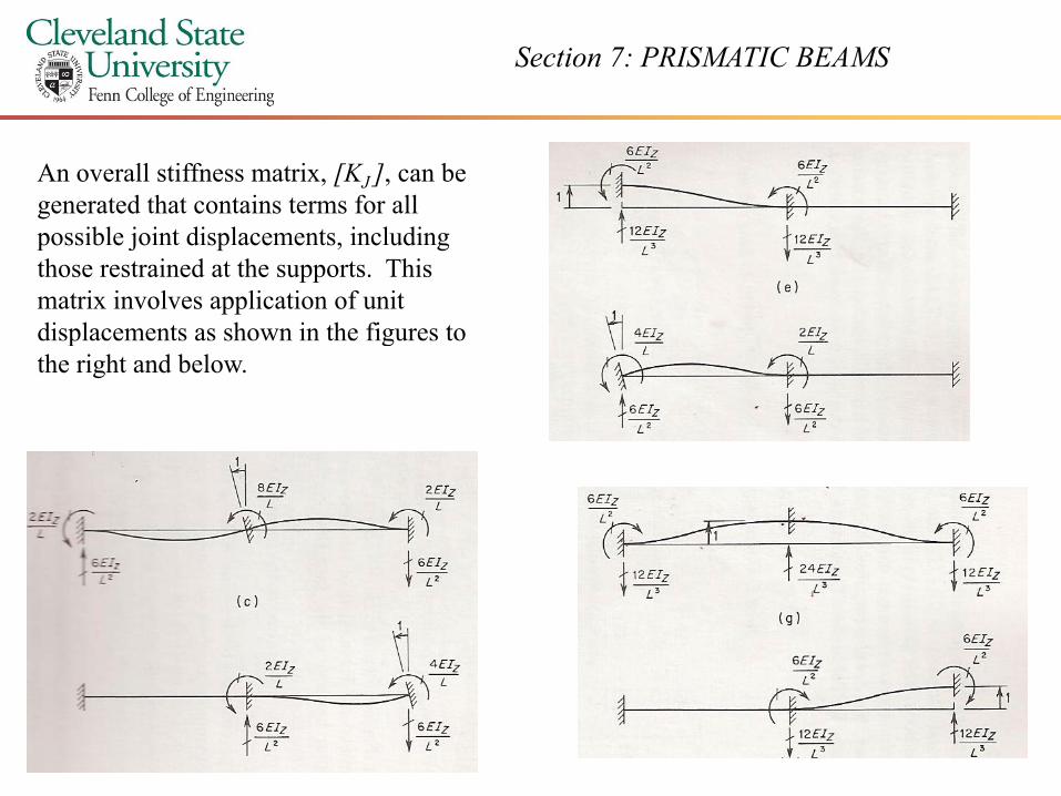
Each column in the stiffness matrix below corresponds to the restraint reactions produced for each unit displacements application in the restrained structure. Each row corresponds to an applied unit displacement There are six possible applied unit displacementsapplied unit displacement. There are six possible applied unit displacements.
Note that the matrix is square and symmetric. Expansion of the determinant of this matrix would demonstrate that the matrix is singular
[K J ] =
that the matrix is singular due to the fact that certain rows and columns are linear combinations of one another.
Section 7: PRISMATIC BEAMS
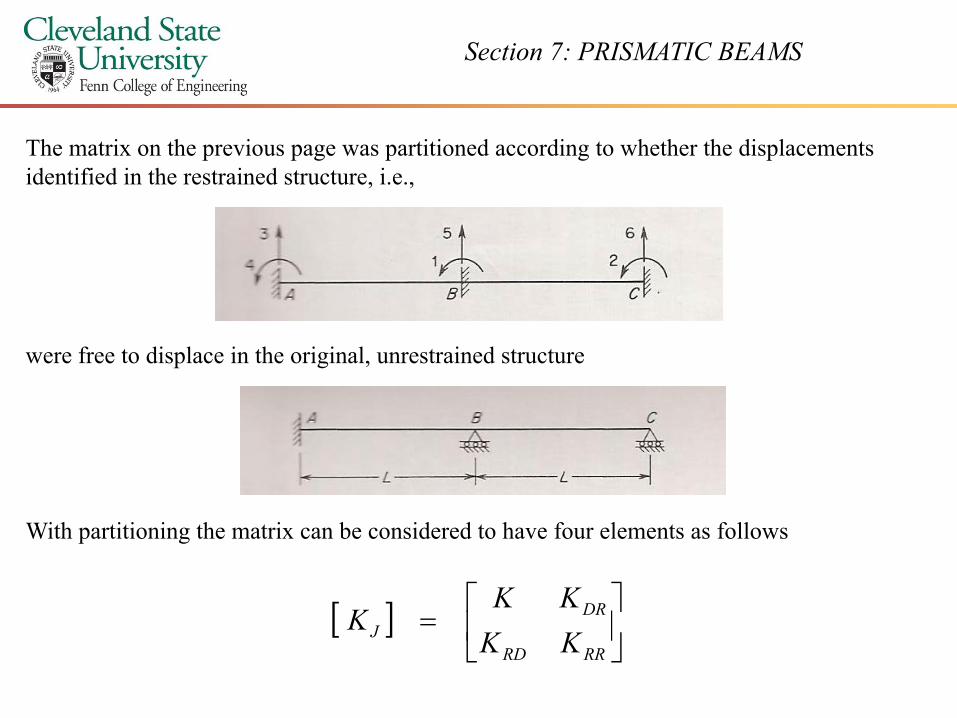
The matrix on the previous page was partitioned according to whether the displacements identified in the restrained structure, i.e.,
were free to displace in the original, unrestrained structure
With partitioning the matrix can be considered to have four elements as follows
[ ]
DRKK
K[ ]
=RRRD
J KKK
Section 7: PRISMATIC BEAMS
The upper left partition, [K], is a square, symmetric matrix that corresponds to the unknown displacements. The inverse of this matrix is used in the expression
{D} = [K]-1 {{AD} – {ADL}}
The lower left partition, {KRD }, is rectangular matrix contains actions that correspond to the support restraints. This partition gives the reactions for the structure due to unit values of the unknown displacements. From the course Matrix Analysis of Structures the vector of support actions (moments or forces) would be obtained from
{AR} = {ARL} + {KRD}{D}
The upper right partition, {KDR }, is simply the transpose of {KRD }. The lower right hand partition, {KRR }, is square and symmetric. It contains actions corresponding to support restraints due to unit displacements in the restrained structure. The matrices {KDR } and {KRR }
ill b d l i i d k di l h iwill be used to analyze reactions associated known support displacements, zero or otherwise.
The stiffness matrix [K] is only a small portion of [KJ]. This is a consequence of the fact that this particular structure is highly restrained to begin with. In large structures having many j i d f h i [K] i l i f [K ]joints and few supports, the matrix [K] constitutes a large portion of [KJ].

Section 7: PRISMATIC BEAMS
In Class Example
Section 7: PRISMATIC BEAMS
Arbitrary Numbering Systems
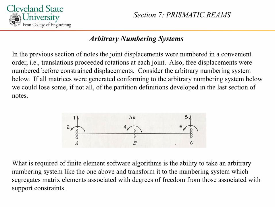
In the previous section of notes the joint displacements were numbered in a convenient order, i.e., translations proceeded rotations at each joint. Also, free displacements were numbered before constrained displacements. Consider the arbitrary numbering system below. If all matrices were generated conforming to the arbitrary numbering system below we could lose some if not all of the partition definitions developed in the last section ofwe could lose some, if not all, of the partition definitions developed in the last section of notes.
What is required of finite element software algorithms is the ability to take an arbitrary numbering system like the one above and transform it to the numbering system which
i l i d i h d f f d f h i d i hsegregates matrix elements associated with degrees of freedom from those associated with support constraints.
Section 7: PRISMATIC BEAMS
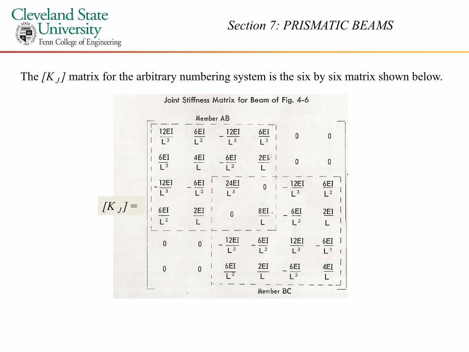
The [K J ] matrix for the arbitrary numbering system is the six by six matrix shown below.
[K J ] =
Section 7: PRISMATIC BEAMS
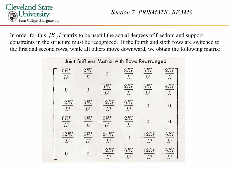
In order for this [K J ] matrix to be useful the actual degrees of freedom and support constraints in the structure must be recognized. If the fourth and sixth rows are switched to the first and second rows while all others move downward we obtain the following matrix:the first and second rows, while all others move downward, we obtain the following matrix:
Section 7: PRISMATIC BEAMS
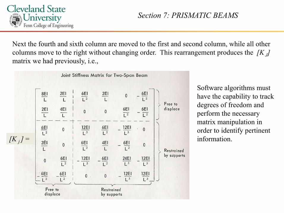
Next the fourth and sixth column are moved to the first and second column, while all other columns move to the right without changing order. This rearrangement produces the [K J]matrix we had previously i ematrix we had previously, i.e.,
Software algorithms must ghave the capability to track degrees of freedom and perform the necessary matrix manipulation inmatrix manipulation in order to identify pertinent information.[K j ] =
Section 7: PRISMATIC BEAMS
Analysis of Continuous Beams in General
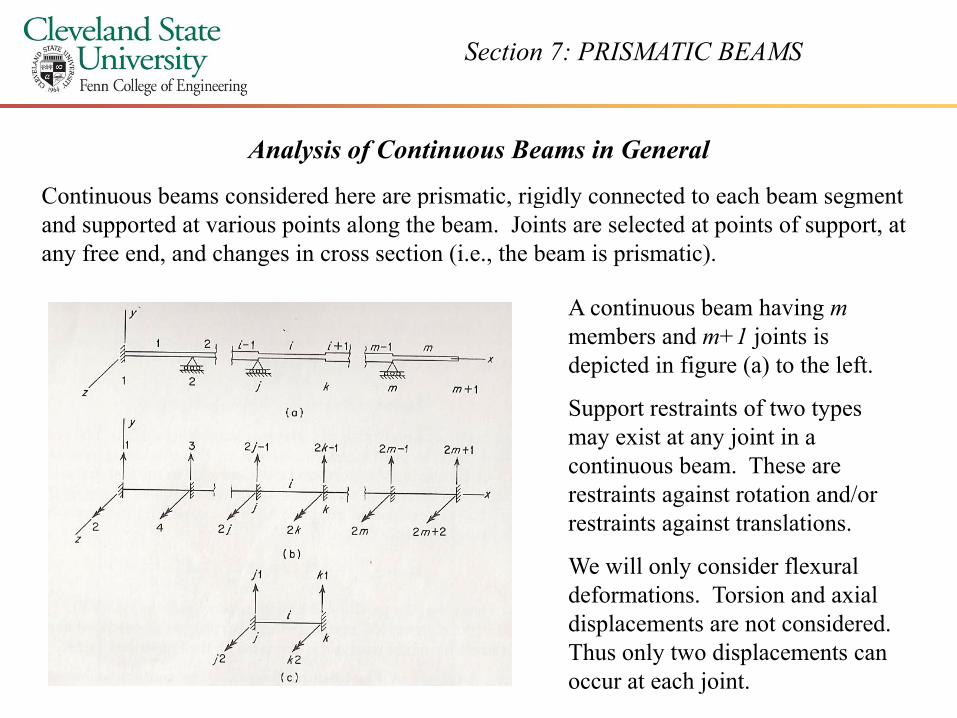
Continuous beams considered here are prismatic, rigidly connected to each beam segment p , g y gand supported at various points along the beam. Joints are selected at points of support, at any free end, and changes in cross section (i.e., the beam is prismatic).
A continuous beam having mA continuous beam having mmembers and m+1 joints is depicted in figure (a) to the left.
Support restraints of two typesSupport restraints of two types may exist at any joint in a continuous beam. These are restraints against rotation and/or restraints against translations.
We will only consider flexural deformations. Torsion and axial di l id ddisplacements are not considered. Thus only two displacements can occur at each joint.
Section 7: PRISMATIC BEAMS
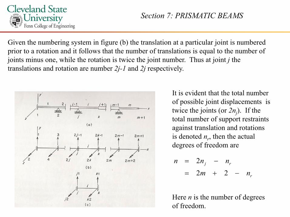
Given the numbering system in figure (b) the translation at a particular joint is numbered prior to a rotation and it follows that the number of translations is equal to the number of joints minus one, while the rotation is twice the joint number. Thus at joint j the joints minus one, while the rotation is twice the joint number. Thus at joint j the translations and rotation are number 2j-1 and 2j respectively.
It is evident that the total numberIt is evident that the total number of possible joint displacements is twice the joints (or 2nj). If the total number of support restraints against translation and rotations is denoted nr, then the actual degrees of freedom are
r
rj
nm
nnn
−+=
−=
22
2
Here n is the number of degrees of freedom.
Section 7: PRISMATIC BEAMS
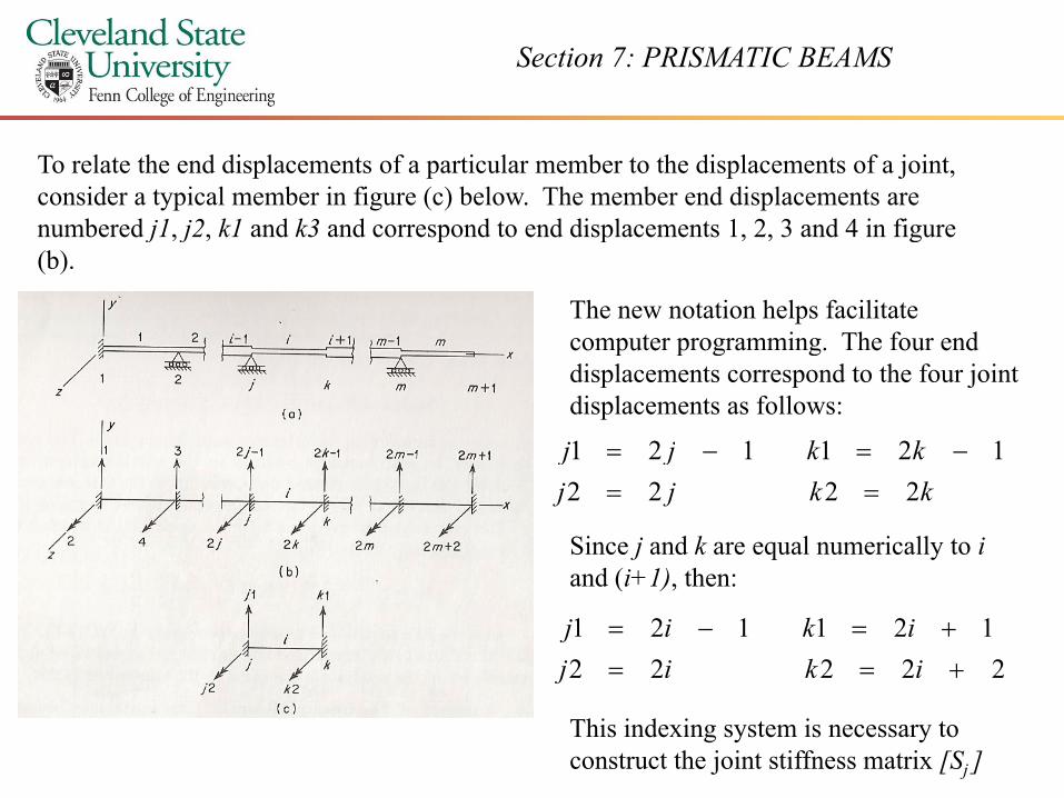
To relate the end displacements of a particular member to the displacements of a joint, consider a typical member in figure (c) below. The member end displacements are numbered j1 j2 k1 and k3 and correspond to end displacements 1 2 3 and 4 in figure
The new notation helps facilitate computer programming The four end
numbered j1, j2, k1 and k3 and correspond to end displacements 1, 2, 3 and 4 in figure (b).
computer programming. The four end displacements correspond to the four joint displacements as follows:
kkjj 121121 −=−=kkjj
kkjj2222
121121==
Since j and k are equal numerically to id (i 1) hand (i+1), then:
22222121121
+==+=−=
ikijikij
This indexing system is necessary to construct the joint stiffness matrix [Sj ]
Section 7: PRISMATIC BEAMS
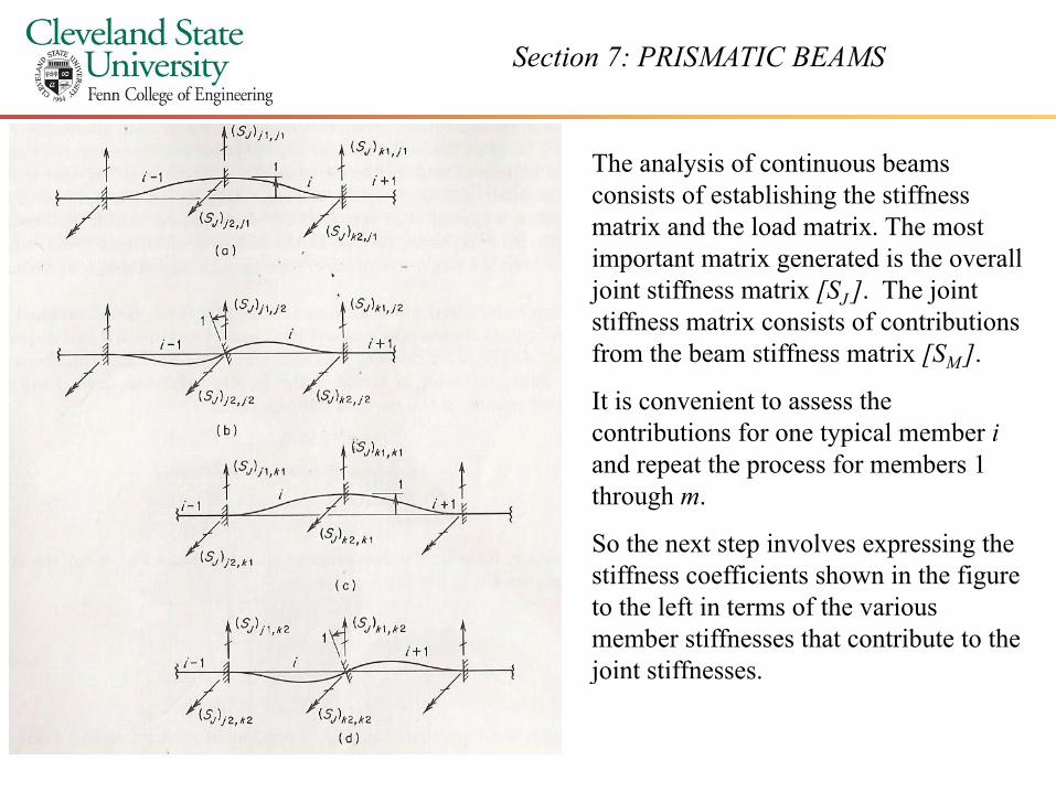
The analysis of continuous beams consists of establishing the stiffness matrix and the load matrix The mostmatrix and the load matrix. The most important matrix generated is the overall joint stiffness matrix [SJ ]. The joint stiffness matrix consists of contributions from the beam stiffness matrix [SM ].
It is convenient to assess the contributions for one typical member iand repeat the process for members 1 through m.
So the next step involves expressing the iff ffi i h i h fistiffness coefficients shown in the figure
to the left in terms of the various member stiffnesses that contribute to the joint stiffnesses.jo t st esses.
Section 7: PRISMATIC BEAMS
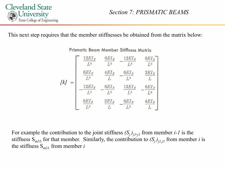
This next step requires that the member stiffnesses be obtained from the matrix below:
[k]
For example the contribution to the joint stiffness (Sj )j1,j1 from member i-1 is the stiffness Sm33 for that member. Similarly, the contribution to (Sj )j1,j1 from member i is th tiff S f b ithe stiffness Sm11 from member i
Section 7: PRISMATIC BEAMS
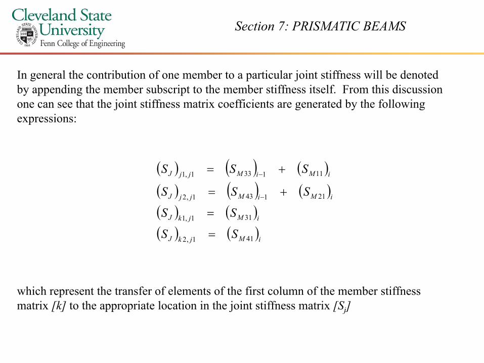
In general the contribution of one member to a particular joint stiffness will be denoted by appending the member subscript to the member stiffness itself. From this discussion one can see that the joint stiffness matrix coefficients are generated by the followingone can see that the joint stiffness matrix coefficients are generated by the following expressions:
( ) ( ) ( )( ) ( ) ( )( ) ( )
iMiMjjJ
iMiMjjJ
SSS
SSS
211431,2
111331,1
+=
+=
−
−
( ) ( )( ) ( )iMjkJ
iMjkJ
SS
SS
411,2
311,1
=
=
which represent the transfer of elements of the first column of the member stiffness matrix [k] to the appropriate location in the joint stiffness matrix [Sj][ ] pp p j [ j]
Section 7: PRISMATIC BEAMS
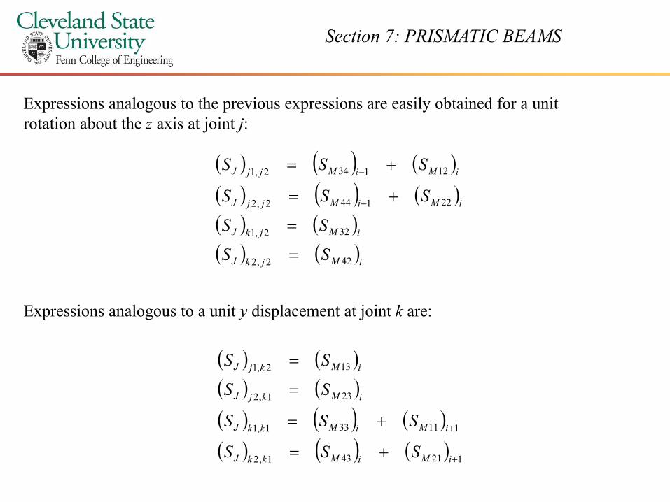
Expressions analogous to the previous expressions are easily obtained for a unit rotation about the z axis at joint j:
( ) ( ) ( )( ) ( ) ( )( ) ( )
iMiMjjJ
iMiMjjJ
SSS
SSS
221442,2
121342,1
+=
+=
−
−
( ) ( )( ) ( )iMjkJ
iMjkJ
SS
SS
422,2
322,1
=
=
Expressions analogous to a unit y displacement at joint k are:
( ) ( )SS( ) ( )( ) ( )( ) ( ) ( ) 1113311
231,2
132,1
++=
=
=
iMiMkkJ
iMkjJ
iMkjJ
SSS
SS
SS
( ) ( ) ( )( ) ( ) ( ) 121431,2
111331,1
+
+
+= iMiMkkJ
iMiMkkJ
SSS
Section 7: PRISMATIC BEAMS
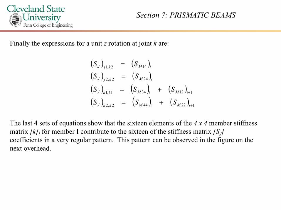
Finally the expressions for a unit z rotation at joint k are:
( ) ( )( ) ( )( ) ( )( ) ( ) ( )
242,2
142,1
+=
=
=
iMkjJ
iMkjJ
SSS
SS
SS
( ) ( ) ( )( ) ( ) ( ) 122442,2
112341,1
+
+
+=
+=
iMiMkkJ
iMiMkkJ
SSS
SSS
The last 4 sets of equations show that the sixteen elements of the 4 x 4 member stiffness matrix [k]i for member I contribute to the sixteen of the stiffness matrix [SJ]coefficients in a very regular pattern. This pattern can be observed in the figure on the next overhead.next overhead.
Section 7: PRISMATIC BEAMS
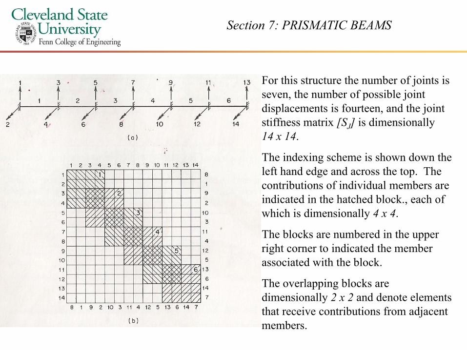
For this structure the number of joints is seven, the number of possible joint p jdisplacements is fourteen, and the joint stiffness matrix [SJ] is dimensionally 14 x 14.
The indexing scheme is shown down the left hand edge and across the top. The contributions of individual members are indicated in the hatched block each ofindicated in the hatched block., each of which is dimensionally 4 x 4.
The blocks are numbered in the upper right corner to indicated the memberright corner to indicated the member associated with the block.
The overlapping blocks are dimensionally 2 x 2 and denote elementsdimensionally 2 x 2 and denote elements that receive contributions from adjacent members.
Section 7: PRISMATIC BEAMS
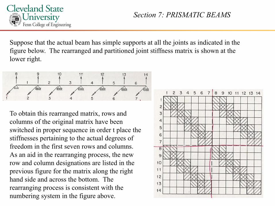
Suppose that the actual beam has simple supports at all the joints as indicated in the figure below. The rearranged and partitioned joint stiffness matrix is shown at the lower rightlower right.
To obtain this rearranged matrix, rows and columns of the original matrix have been switched in proper sequence in order t place the stiffnesses pertaining to the actual degrees of freedom in the first seven rows and columnsfreedom in the first seven rows and columns. As an aid in the rearranging process, the new row and column designations are listed in the previous figure for the matrix along the right hand side and across the bottom. The rearranging process is consistent with the numbering system in the figure above.
Section 7: PRISMATIC BEAMS
In summary, the procedure followed in generating the joint stiffness matrix [SJ ]consists of taking the members in sequence and evaluating their contributions one at a time Then the stiffness matrix [k] is generated and the elements of this matrix aretime. Then the stiffness matrix [k]i is generated, and the elements of this matrix are transferred to the [SJ ] as indicated in the previous overheads. After all members have been processed in this manner, the [SJ ] matrix is complete. This matrix can be rearranged and partitioned in order to isolate the [S] matrix. The inverse of this matrix is then determined and the unknown displacements are computed.
Section 7: PRISMATIC BEAMS
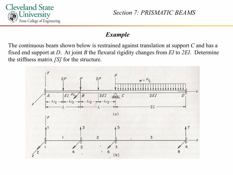
ExampleThe continuous beam shown below is restrained against translation at support C and has a fixed end support at D. At joint B the flexural rigidity changes from EI to 2EI. Determine the stiffness matrix [S] for the structure.
Section 7: PRISMATIC BEAMS
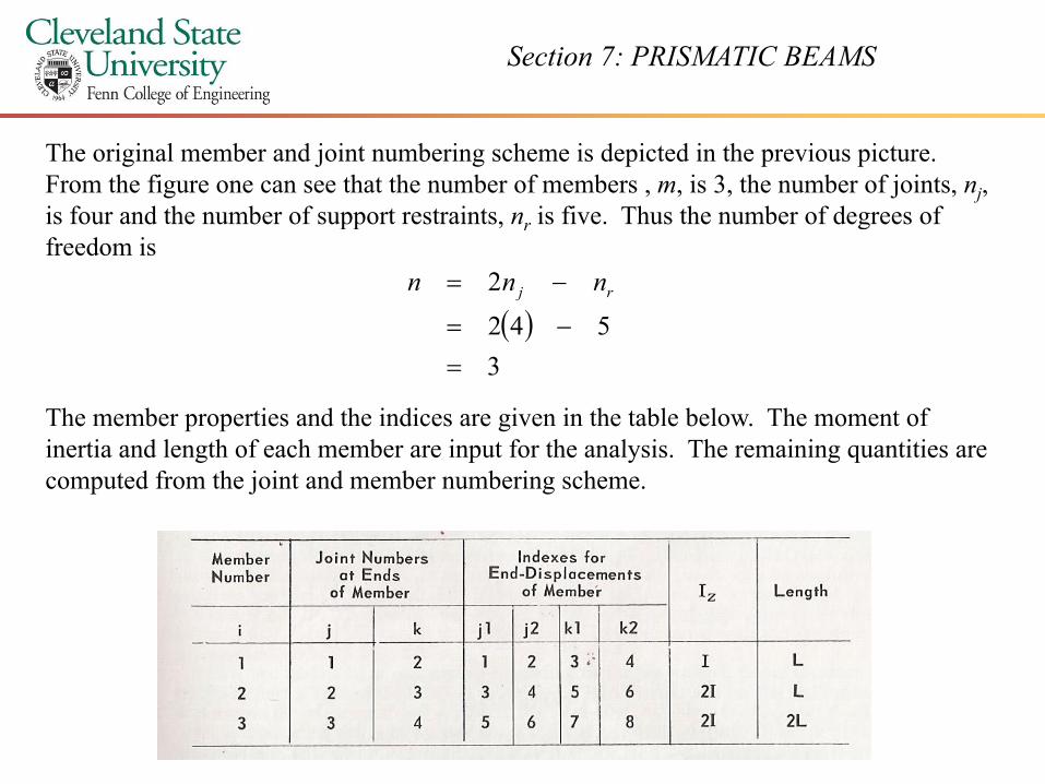
The original member and joint numbering scheme is depicted in the previous picture. From the figure one can see that the number of members , m, is 3, the number of joints, nj, is four and the number of support restraints, nr is five. Thus the number of degrees of
( ) 542
2
−=
−= rj nnn
is four and the number of support restraints, nr is five. Thus the number of degrees of freedom is
( )3=
The member properties and the indices are given in the table below. The moment of inertia and length of each member are input for the analysis The remaining quantities areinertia and length of each member are input for the analysis. The remaining quantities are computed from the joint and member numbering scheme.
Section 7: PRISMATIC BEAMS
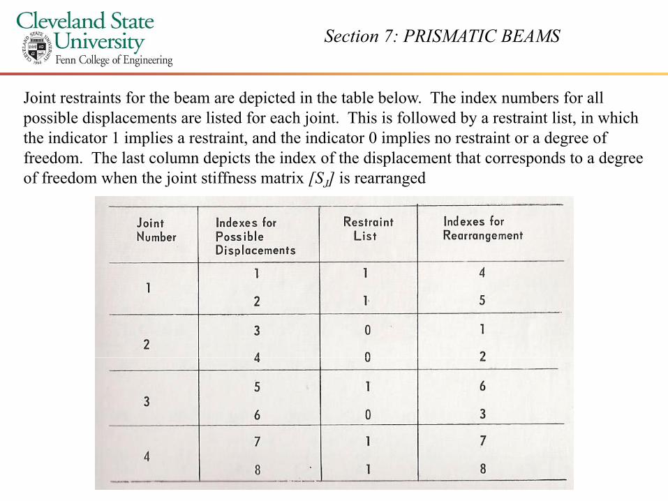
Joint restraints for the beam are depicted in the table below. The index numbers for all possible displacements are listed for each joint. This is followed by a restraint list, in which the indicator 1 implies a restraint, and the indicator 0 implies no restraint or a degree of the indicator 1 implies a restraint, and the indicator 0 implies no restraint or a degree of freedom. The last column depicts the index of the displacement that corresponds to a degree of freedom when the joint stiffness matrix [SJ] is rearranged
Section 7: PRISMATIC BEAMS
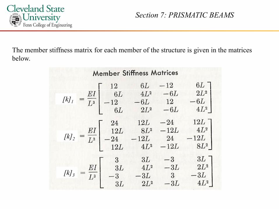
The member stiffness matrix for each member of the structure is given in the matrices belowbelow.
[k]1
[k]2
[k]3
Section 7: PRISMATIC BEAMS
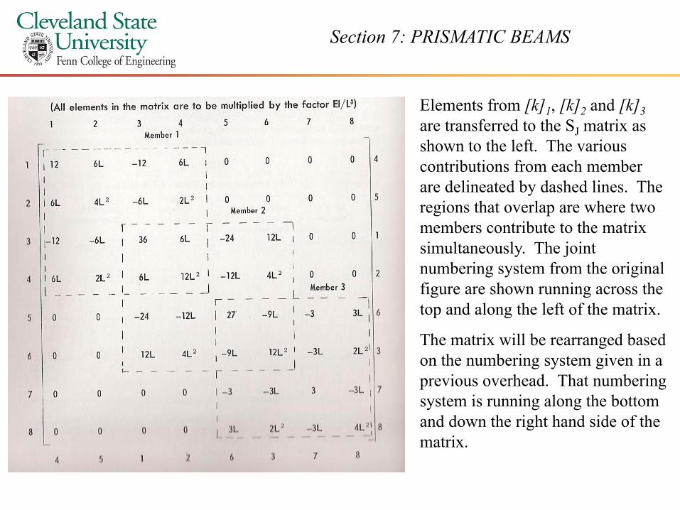
Elements from [k]1, [k]2 and [k]3are transferred to the SJ matrix as shown to the left The variousshown to the left. The various contributions from each member are delineated by dashed lines. The regions that overlap are where two members contribute to the matrix simultaneously. The joint numbering system from the original figure are shown running across thefigure are shown running across the top and along the left of the matrix.
The matrix will be rearranged based on the numbering system given in aon the numbering system given in a previous overhead. That numbering system is running along the bottom and down the right hand side of the
imatrix.
Section 7: PRISMATIC BEAMS
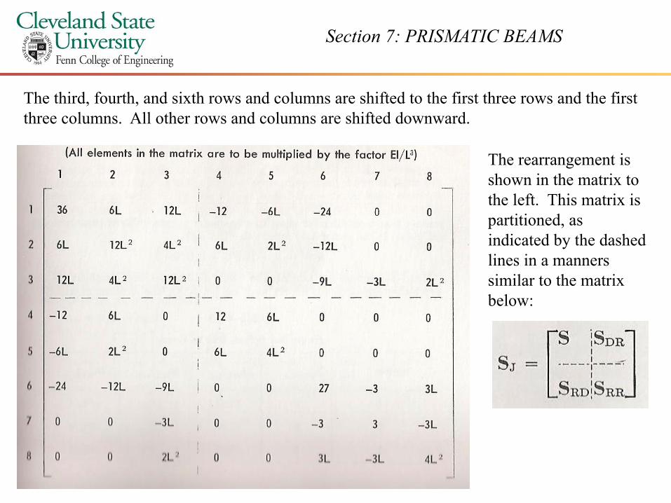
The third, fourth, and sixth rows and columns are shifted to the first three rows and the first three columns. All other rows and columns are shifted downward.
The rearrangement is shown in the matrix to the left. This matrix is
titi dpartitioned, as indicated by the dashed lines in a manners similar to the matrix below:
Section 7: PRISMATIC BEAMS
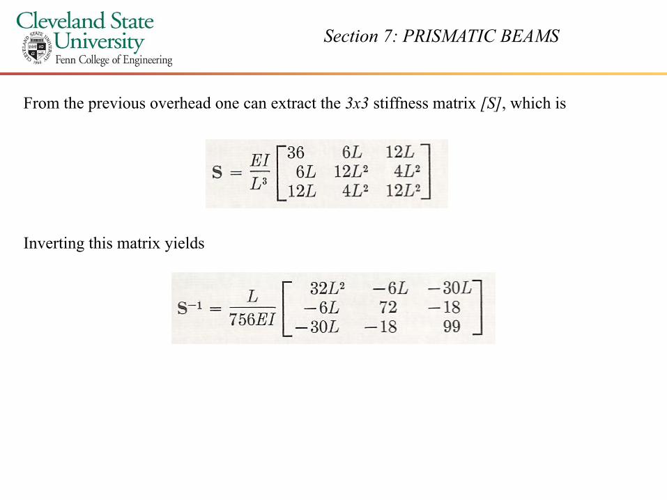
From the previous overhead one can extract the 3x3 stiffness matrix [S], which is
Inverting this matrix yields


![1 CST ELEMENT STIFFNESS MATRIX Strain energy –Element Stiffness Matrix: –Different from the truss and beam elements, transformation matrix [T] is not](https://img.dokumen.tips/doc/110x75/56649d6f5503460f94a518a4/1-cst-element-stiffness-matrix-strain-energy-element-stiffness-matrix-different.jpg)