Embed Size (px)
Citation preview

Micro Motion®
Modbus® Interface Tool
Getting Started Manual
Instruction ManualP/N MMI-20011275, Rev. ACNovember 2016


Getting Started Manual i
Contents
Chapter 1 Before You Begin . . . . . . . . . . . . . . . . . . . . . . . . . . . . . . . . . . . . . 11.1 About this manual . . . . . . . . . . . . . . . . . . . . . . . . . . . . . . . . . . . . . . . . . . . . . . . . . . . . 11.2 About the Modbus Interface Tool. . . . . . . . . . . . . . . . . . . . . . . . . . . . . . . . . . . . . . . . . 1
1.2.1 Requirements. . . . . . . . . . . . . . . . . . . . . . . . . . . . . . . . . . . . . . . . . . . . . . . 21.2.2 Transmitters included in the Modbus Interface Tool . . . . . . . . . . . . . . . . . . 2
1.3 Micro Motion customer service . . . . . . . . . . . . . . . . . . . . . . . . . . . . . . . . . . . . . . . . . . 3
Chapter 2 Using the Modbus Interface Tool. . . . . . . . . . . . . . . . . . . . . . . . . . . 52.1 About this chapter . . . . . . . . . . . . . . . . . . . . . . . . . . . . . . . . . . . . . . . . . . . . . . . . . . . . 52.2 Installing and running the Modbus Interface Tool . . . . . . . . . . . . . . . . . . . . . . . . . . . . 52.3 Macros and macro substitutes . . . . . . . . . . . . . . . . . . . . . . . . . . . . . . . . . . . . . . . . . . 52.4 Modbus Interface Tool structure . . . . . . . . . . . . . . . . . . . . . . . . . . . . . . . . . . . . . . . . . 52.5 Selecting the transmitter . . . . . . . . . . . . . . . . . . . . . . . . . . . . . . . . . . . . . . . . . . . . . . . 62.6 Using filters and keywords . . . . . . . . . . . . . . . . . . . . . . . . . . . . . . . . . . . . . . . . . . . . . 62.7 Using hyperlinks . . . . . . . . . . . . . . . . . . . . . . . . . . . . . . . . . . . . . . . . . . . . . . . . . . . . . 6
2.7.1 Viewing the information at the hyperlink destination . . . . . . . . . . . . . . . . . 62.7.2 Hyperlink Base. . . . . . . . . . . . . . . . . . . . . . . . . . . . . . . . . . . . . . . . . . . . . . 7
Chapter 3 Modbus Protocol on Micro Motion Transmitters . . . . . . . . . . . . . . . . 93.1 About this chapter . . . . . . . . . . . . . . . . . . . . . . . . . . . . . . . . . . . . . . . . . . . . . . . . . . . . 93.2 Modbus address . . . . . . . . . . . . . . . . . . . . . . . . . . . . . . . . . . . . . . . . . . . . . . . . . . . . . 93.3 Transmitter registers and data types . . . . . . . . . . . . . . . . . . . . . . . . . . . . . . . . . . . . . . 9
3.3.1 Register addresses . . . . . . . . . . . . . . . . . . . . . . . . . . . . . . . . . . . . . . . . . . 93.3.2 Register types . . . . . . . . . . . . . . . . . . . . . . . . . . . . . . . . . . . . . . . . . . . . . . 9
3.4 Message framing. . . . . . . . . . . . . . . . . . . . . . . . . . . . . . . . . . . . . . . . . . . . . . . . . . . . 123.4.1 Address field . . . . . . . . . . . . . . . . . . . . . . . . . . . . . . . . . . . . . . . . . . . . . . 133.4.2 Function field . . . . . . . . . . . . . . . . . . . . . . . . . . . . . . . . . . . . . . . . . . . . . . 133.4.3 Data field . . . . . . . . . . . . . . . . . . . . . . . . . . . . . . . . . . . . . . . . . . . . . . . . . 143.4.4 Error check field . . . . . . . . . . . . . . . . . . . . . . . . . . . . . . . . . . . . . . . . . . . . 17
3.5 Data transmission modes . . . . . . . . . . . . . . . . . . . . . . . . . . . . . . . . . . . . . . . . . . . . . 173.5.1 Message framing in ASCII mode . . . . . . . . . . . . . . . . . . . . . . . . . . . . . . . 173.5.2 Message framing in RTU mode . . . . . . . . . . . . . . . . . . . . . . . . . . . . . . . . 18
3.6 Error checking . . . . . . . . . . . . . . . . . . . . . . . . . . . . . . . . . . . . . . . . . . . . . . . . . . . . . . 183.6.1 Parity checking. . . . . . . . . . . . . . . . . . . . . . . . . . . . . . . . . . . . . . . . . . . . . 183.6.2 Longitudinal redundancy check sequence (ASCII mode) . . . . . . . . . . . . 193.6.3 Cyclic redundancy check (RTU mode). . . . . . . . . . . . . . . . . . . . . . . . . . . 21

ii Micro Motion® Modbus® Interface Tool

Getting Started Manual 1
Usin
g th
e Mo
dbu
s Interface To
ol
M
od
bus P
roto
col
Befo
re You
Beg
in
Chapter 1Before You Begin
1.1 About this manualThis manual provides an introduction to the Micro Motion® Modbus® Interface Tool. This manual also provides a short description of the Modbus protocol and how it has been implemented by Micro Motion.
Note: This manual does not address Modbus programming requirements and techniques in detail. For Modbus programming specifications, see http://www.modbus.org.
This manual assumes that the programmer is already familiar with the Micro Motion transmitter at a functional level. If required, obtain the appropriate transmitter manual and refer to it for information on transmitter features and functions.
1.2 About the Modbus Interface ToolThe Modbus Interface Tool is designed to provide the Modbus information required to configure, use, and troubleshoot a Micro Motion transmitter via Modbus protocol. For example, for each transmitter, the Modbus Interface Tool provides a list of all Modbus coils and registers supported by that transmitter, with:
• Address, data type, and length information
• Read/write vs. read-only information
• Quick definitions
• Transmitter version information
• Hyperlinks to supplementary notes or procedures
• Hyperlinks to integer codes, if required
• Keywords
Using this information, plus information provided in the appropriate transmitter manual, the programmer can use the Modbus interface to:
• Read process data
• Reset totalizers and inventories
• Run batches or fills
• Read alarm status and acknowledge alarms
• Read and interpret diagnostic data
1.2.1 Transmitters included in the Modbus Interface ToolAlthough most Micro Motion transmitters support Modbus protocol via the service port, the Modbus Interface Tool includes only transmitters with dedicated Modbus/RS-485 terminals, as listed in Table 1-1.

2 Micro Motion® Modbus® Interface Tool
Before You Begin
Note: MVD Direct Connect installations do not include a transmitter. However, a Modbus/RS-485 connection can be made to the core processor component, and Modbus commands can be used to communicate with the core processor. See the MVD Direct Connect flowmeter installation manual for information on setting up this connection.
Table 1-1 Transmitters included in the Modbus Interface Tool
Transmitter Model number
MVD™ Direct Connect™ with the standard core processor Electronics interface code W, D, Y, or E in sensor model code
MVD™ Direct Connect™ with the enhanced core processor Electronics interface code 6 or 8 in sensor model code
RFT9739 RFT9739*******
9739 MVD 9739MVD********
Model 1500 1500**********
Model 1500 with the Filling and Dosing Application 1500*******B**
Model 1700 with analog outputs 1700***A******
Model 2500 2500**********
Model 2700 with analog outputs 2700***A******
Model 5700 with configurable outputs 5700*********
Model 5700 with Ethernet transmitters 5700*********
LF-Series 1 mA/1 FO flow-only field-mount LFT1*******
LF-Series 2 mA/1 FO flow-only DIN rail mount LFT2*******
LF-Series 3 mA/1 FO multi-variable field-mount LFT3*******
LF-Series 5 2 mA/1 FO configurable multivariable DIN rail mount
LFT5*******
Series 3000 MVD (4-wire) 3**0****5*****3**0****5*******3**0****6*****3**0****6*******
Series 3000 NOC (9-wire) 3**0****3***N*3**0****3*****N*
Series 3000 MVD NOC (4-wire) 3**0****5***N*3**0****5*****N*3**0****6***N*3**0****6*****N*
Filling Mass Transmitter (FMT) FMT**********

Getting Started Manual 5
Usin
g th
e Mo
dbu
s Interface To
ol
M
od
bus P
roto
col
Befo
re You
Beg
in
Chapter 2Using the Modbus Interface Tool
2.1 About this chapterThis chapter provides basic instructions for using the Modbus Interface Tool.
Note: Instructions assume that you are using Excel 2007. If you are using another version of Excel, adapt the instructions as required.
2.2 Installing and running the Modbus Interface Tool
The Modbus Interface Tool is provided on an installation CD or in a self-extracting file that can be downloaded from the Micro Motion web site.
To install the Modbus Interface Tool:
1. Insert the installation CD into the CD drive on your PC, or download the self-extracting file to a convenient location on your PC.
2. Run the Setup file.
3. Follow the onscreen instructions.
The installation program will create a desktop shortcut for the Modbus Interface Tool. To start the program, click the icon or click Start>Programs>MMI>Modbus Interface Tool.
2.3 Macros and macro substitutes
In the Modbus Interface Tool, macros are used for the following functions:
• Selecting the transmitter you want to work with
• Resizing the window for your monitor
If macros are not enabled in your Excel installation, you will see an error message when you use the Select buttons on the Welcome panel. Micro Motion recommends enabling macros for this spreadsheet if possible. Use standard Excel techniques.
If you cannot enable Excel macros for the Modbus Interface tool:
• To select the transmitter you want to work with, click View>Custom Views and select the desired view from the list. See Section 2.5 for more information.
• To resize the window for your monitor, use standard Windows controls.
2.4 Modbus Interface Tool structure
The Modbus Interface Tool is organized as a set of worksheets within an Excel spreadsheet. Standard Excel features are used to order and present the information, as described in the following sections.

6 Micro Motion® Modbus® Interface Tool
Using the Modbus Interface Tool
You can use any Excel feature available on your system to make the Modbus Interface Tool more convenient or customized for you. For example, using standard Excel methods, you can:
• Set up site-specific reports and printing instructions
• Change the sort order
• Change the Freeze Panes setting
• Show or hide different columns
The Modbus Interface Tool is not write-protected. You can save your custom version over the installed spreadsheet or to a new file. If you save to a new file, be sure to update the desktop shortcut appropriately or create a shortcut for your custom version.
2.5 Selecting the transmitterThe Modbus Interface Tool assumes that you want to see Modbus information for only one transmitter at a time. The Welcome worksheet provides a list of transmitters. Click the Select button for the transmitter you are working with, and a custom view for that transmitter will be displayed.
To view information for a different transmitter, return to the Welcome worksheet and click the Select button for the new transmitter.
To view information for all transmitters at once, return to the Welcome worksheet and click the Select button for the “All Products” option.
2.6 Using filters and keywordsThe Modbus Interface Tool is shipped with filters enabled. Filters are an Excel feature that allow you to view only rows that contain predefined data. For example:
• You can define a filter on the Used column to see only rows that are active for your transmitter.
• You can define a filter on the Keywords column to see only rows associated with the selected keyword.
Use standard Excel methods to define and use filters.
2.7 Using hyperlinksThe Modbus Interface Tool uses Excel hyperlinks to display supplementary information for each coil and register. You can view this information as desired.
2.7.1 Viewing the information at the hyperlink destination
If you want to see the information at the hyperlink destination, click the hyperlink.
To return to your original location after viewing the information, click the Back button. In Excel 2007, the Back arrow is not on the ribbon. To use it, you must add it to the Quick Access Toolbar.

Getting Started Manual 7
Using the Modbus Interface ToolU
sing
the M
od
bus In
terface Too
l
Mo
dbu
s Pro
toco
lB
efore Yo
u B
egin
2.7.2 Hyperlink Base
If you receive the following message when you click a hyperlink:Cannot open the specified file
check that the Hyperlink Base is set correctly.
In a typical installation, the Hyperlink Base is blank, so that it defaults to the installation directory. However, if you have moved the Modbus Interface Tool or changed directory or file names, you may need to verify that the Hyperlink Base is blank, or update it manually. To do this in Excel 2007:
1. Click the Microsoft Office button, then click Prepare>Properties.
2. In the Document Information Panel, click Document Properties>Advanced Properties, and select the Summary panel.
3. In the Hyperlink Base field, delete the contents or enter the name and location of the Modbus Interface Tool on your PC.
4. Click OK.

8 Micro Motion® Modbus® Interface Tool

Getting Started Manual 9
Usin
g th
e Mo
dbu
s Interface To
ol
M
od
bus P
roto
col
Befo
re You
Beg
in
Chapter 3Modbus Protocol on Micro Motion Transmitters
3.1 About this chapterThis chapter provides an introduction to using Modbus protocol with Micro Motion transmitters.
Note: This is not a complete definition of the Modbus interface. For more information on programming to the Modbus interface, see www.modbus.org.
3.2 Modbus address
A Micro Motion transmitter emulates a programmable logic controller (PLC) that communicates with a Modbus-compatible host controller in a multidrop network. Each transmitter has a unique Modbus address. The host uses a non-zero polling address to initiate communication with a single transmitter, or a polling address of 0 to broadcast a message to all network devices.
3.3 Transmitter registers and data types
The transmitter can accept, store, and return boolean values, integers, floating-point values, and ASCII characters, regardless of the data transmission mode (7-bit ASCII or 8-bit RTU) used by the host controller. The different data types are stored in different register types in transmitter memory. Each register type has different requirements for reading or writing.
3.3.1 Register addressesEach register is identified by its address (or starting address), which is a 4-digit number.
Depending on the PLC that will be used to communicate with the transmitter, you may need to subtract 1 from the address or starting address of the register. Refer to your PLC documentation to know if this applies to you.
3.3.2 Register types The register types are listed and briefly described in Table 3-1. More detailed descriptions are provided following the table.
Note: Micro Motion terminology is a simplified version of Modbus terminology. The term “coil” is used for both Modbus coils (read-write) and Modbus discrete inputs (read-only), and the term “register” is used for both Modbus holding registers (read-write) and Modbus input registers (read-only).
Example The Modbus Interface Tool specifies 42 as the address of the register that contains the unit for process variables that measure volume flow.
Use 41 in the data field of the Modbus frame.

10 Micro Motion® Modbus® Interface Tool
Modbus Protocol on Micro Motion Transmitters
Coils
There are three types of coil:
• Read-only. These coils can be read through Modbus functions 1 or 2. Function 7, used with RFT9739 transmitters, MVD Direct Connect systems, or other systems with Modbus wiring direct to the core processor, will return the values of coils 21–28.
• Read-write “sticky” coils, i.e., coils that retain the value written to them. For example, totalizer start/stop coils are sticky. These coils can be read through Modbus functions 1 or 2, and written using Modbus function 5 (see Section 3.4.2).
• Read-write “momentary” coils, i.e., coils that initiate an action when written as ON, and switch back to OFF either immediately or when the process is complete. For example, the coils used to initiate calibration are momentary. These coils can be read through Modbus functions 1 or 2, and written using Modbus function 5 (see Section 3.4.2).
Modbus function 1 or 2 is used to read either a single coil or a group of consecutive coils. Each bit within the data bytes represents a single coil, with lower addresses represented by lower-order bits within the byte. If more than 8 coils are read, the first 8 will be read from the first byte, the next 8 from the next byte, and so on. The last data byte read may contain fewer than 8 coils, with the high-order bit(s) set to 0. In each of these cases, 1 represents ON and 0 represents OFF.
Modbus function 5 is used to write a single coil (read-write coils only). The data value 65,280 (FF00 hex) sets the coil ON, and 0 turns the coil OFF.
Modbus function 15 is used to write a group of consecutive coils. In this case, each bit within the data bytes represents a single coil, with lower addresses represented by lower-order bits within the byte. If more than 8 coils are written, the first 8 coils will be written in the first byte, the next 8 coils in the next byte, and so on. The last data byte transmitted may contain fewer than 8 coils, with the high order bit(s) as don't care. In each of these cases a 1 turns the coil ON and a 0 turns the coil OFF.
Integer registersModbus function 3 or 4 (see Section 3.4.2) is used to read a single integer register or a group of consecutive integer registers. If the registers are non-consecutive, a separate command must be used for each register.
Note: To read several non-consecutive registers with a single command, use slot addresses. See Micro Motion Modbus Interface Tool Slots and Slot Address Sequences.
Modbus function 6 is used to write a single integer register (read-write registers only). Modbus function 16 is used to write a group of consecutive integer registers (see Section 3.4.2).
Table 3-1 Modbus register types
Register type Size Data type Description
Coil 1 bit Binary Boolean (0 or 1, ON or OFF)
Float 16 bit Floating-point Used in pairs to store 32-bit floating-point values in single precision IEEE 754 format
Integer 16 bit Integer Unsigned 16-bit integers ranging from 0 to 65535
Long integer 16 bit Integer Used in pairs to store unsigned 32-bit integers ranging from 0 to 4294967295 (0xFFFFFFFF).
ASCII 16 bit 8-bit ASCII One or more consecutive registers. Each register stores two 8-bit ASCII characters (16 bits total).

Getting Started Manual 11
Modbus Protocol on Micro Motion TransmittersU
sing
the M
od
bus In
terface Too
l
Mo
dbu
s Pro
toco
lB
efore Yo
u B
egin
Integers are transmitted high-order byte first. If multiple registers are read or written in a single command, data are transmitted from consecutive registers, beginning with the register that has the lowest address.
Long integer registersSome integer values used by the transmitter are larger than 65,535, which is the largest number that can be stored in a single integer register. In these cases, the value is stored in two consecutive integer registers. These “long integer” registers are read and written using the Modbus functions 3, 4, and 16 (see Section 3.4.2). The most significant word is stored in the lower register, and the least significant word is stored in the higher register.
When reading and writing long integer values, partial numbers are not permitted by the transmitter. Because of this, long integer values must be written using command 16 (see Section 3.4.2).
Float registers
Register pairs are used to store single-precision IEEE 754 floating-point values. A register pair consists of two consecutive 16-bit registers.
When reading and writing floating-point data, partial numbers are not permitted by the transmitter. Because of this, floating-point data must be written using command 16 (see Section 3.4.2). Byte order is configurable (as discussed later in this section).
Float register pairs are read using a single command. Multiple values can be read with a single command, if the register pairs are consecutive. If they are non-consecutive, a separate command must be used for each register pair.
Note: To read several non-consecutive register pairs with a single command, use slot addresses. See Micro Motion Modbus Interface Tool Slots and Slot Address Sequences.
Data is written to the register pair using a single command. Multiple values can be written with a single command, if the register pairs are consecutive. If they are non-consecutive, a separate command must be used for each register pair.
Each floating-point value contains four bytes. Each byte always has the same contents, independent of the byte order. Byte contents are shown below:
where:
• S = sign of the mantissa
- 0 = positive
- 1 = negative
• E = exponent, biased by 127 (e.g., a value of 200 indicates an exponent of 73)
• M = mantissa, 23 least significant bits, fractional portion
The value of the floating-point number is constructed as shown below. The 24-bit mantissa is composed of an assumed most significant bit of 1, a decimal point following the 1, and the 23 bits of the mantissa:
Byte #0 Byte #1 Byte #2 Byte #3
S E E E E E E E E M M M M M M M M M M M M M M M M M M M M M M M
S1M 2E 127–

12 Micro Motion® Modbus® Interface Tool
Modbus Protocol on Micro Motion Transmitters
Invalid data, such as bad process variable, are represented by the hexadecimal (not a number) value for your transmitter:
• RFT9739 transmitters: 00 00 7F A0
• MVD transmitters: 7F A0 00 00
The RFT9739 transmitter must receive and send floating-point data in the following byte order:
2–3 0–1
MVD transmitters can receive and send floating-point data in the following byte orders:
0–1 2–3
2–3 0–1 (default)
1–0 3–2
3–2 1–0
ASCII registersModbus functions 3, 4, 6, and 16 are used to read and write ASCII registers (see Section 3.4.2). String values are padded to 4, 8, 16, or 32 characters. The space character is used to pad data read from the transmitter, and don’t care is used to pad data sent to the transmitter.
When reading or writing ASCII registers, the first register must always be read or written. You can read or write the first register, the first two registers, the first three registers, and so on. The registers must be read or written with one command. More than one character string can be read or written in a single command, if the ASCII registers are consecutive.
Note: To read several non-consecutive ASCII register sets with a single command, use slot addresses. See Micro Motion Modbus Interface Tool Slots and Slot Address Sequences.
3.4 Message framingModbus messages are structured in frames. In general, each frame contains an address field, a function field, a data function field, and an error check field. Frames are structured and transmitted differently depending on the data transmission mode (see Section 3.5).
There are three frame types:
• Query frames are used to address a single network device. The network device responds with a response frame. The combination of one query frame and one response frame is called a query/response message.
• Broadcast frames are used to address all devices on the network. The devices do not respond. Each broadcast frame constitutes one broadcast message. Any frame with a value of 0 in the address field is a broadcast frame.
Only Modbus function codes 5, 6, 8, 15, and 16 are valid in a broadcast message. Every slave device on a multidrop network will receive a broadcast message and perform the requested action, and no slave will respond, which is why no read functions are supported in a broadcast message.
Because of its use in broadcast messages, address 0 is not useful as a Modbus polling address.

Getting Started Manual 13
Modbus Protocol on Micro Motion TransmittersU
sing
the M
od
bus In
terface Too
l
Mo
dbu
s Pro
toco
lB
efore Yo
u B
egin
3.4.1 Address field
In a query frame, the address field contains a transmitter's polling address.
In a response frame, the address field contains the polling address of the responding device.
In a broadcast frame, the address field contains a 0, which tells the network devices not to reply.
3.4.2 Function fieldThe function field contains a Modbus function code. Micro Motion’s Modbus interface uses a subset of function codes supported by all Modbus hosts. The function codes used by Micro Motion’s Modbus interface are listed and defined in Table 3-2.
In Table 3-2:
• Functions 01 and 02 as used by Micro Motion perform the same processing, and are interchangeable.
• Functions 03 and 04 as used by Micro Motion perform the same processing, and are interchangeable.
In a query frame or broadcast frame, the function code specifies a read command, write command, or diagnostic command to be applied to the register specified in the data field.
In a response frame, the function code is used to verify the device's response to the command:
• If no error occurred, the transmitter echoes the original function code. The data field contains the start register and the value sent, or the start register and the function number. See Section 3.4.3.
• If an error occurred, the most significant bit in the function field is set. The data field contains an exception response explaining any errors encountered processing the command.
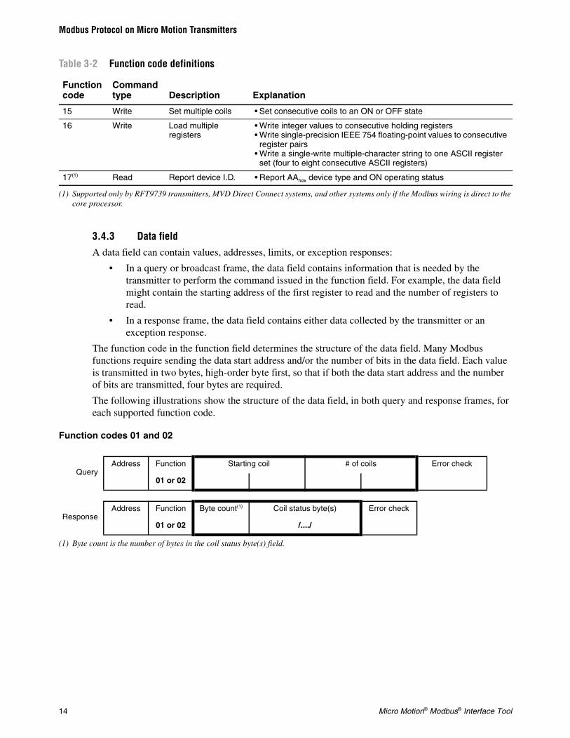
Table 3-2 Function code definitions
Function code
Command type Description Explanation
0102
Read Read coil status • Read status of one coil or consecutive coils
0304
Read Read integer, float, or ASCII registers
• Read integer values in one holding register or consecutive holding registers
• Read floating-point values in one register pair or consecutive register pairs
• Read character strings in consecutive ASCII registers
05 Write Set coil • Set coil to a specified ON or OFF state
06 Write Load register • Write an integer value to an integer register
07(1) Diagnostic Read exception status
Read ON/OFF status of status bits that comprise the high-order byte of register 0125. Micro Motion has programmed these bits to indicate flowmeter status. They include:• Bit #0(E)EPROM checksum failure• Bit #1RAM diagnostic failure• Bit #2Sensor failure• Bit #3Temperature sensor failure• Bit #4Input overrange• Bit #5Frequency overrange• Bit #6Transmitter not configured• Bit #7Real-time interrupt failure
08(1) Diagnostic Loopback diagnostic • Send test message to transmitter to evaluate communication processing
14 Micro Motion® Modbus® Interface Tool
Modbus Protocol on Micro Motion Transmitters
3.4.3 Data fieldA data field can contain values, addresses, limits, or exception responses:
• In a query or broadcast frame, the data field contains information that is needed by the transmitter to perform the command issued in the function field. For example, the data field might contain the starting address of the first register to read and the number of registers to read.
• In a response frame, the data field contains either data collected by the transmitter or an exception response.
The function code in the function field determines the structure of the data field. Many Modbus functions require sending the data start address and/or the number of bits in the data field. Each value is transmitted in two bytes, high-order byte first, so that if both the data start address and the number of bits are transmitted, four bytes are required.
The following illustrations show the structure of the data field, in both query and response frames, for each supported function code.
Function codes 01 and 02
15 Write Set multiple coils • Set consecutive coils to an ON or OFF state
16 Write Load multiple registers
• Write integer values to consecutive holding registers• Write single-precision IEEE 754 floating-point values to consecutive
register pairs• Write a single-write multiple-character string to one ASCII register
set (four to eight consecutive ASCII registers)
17(1) Read Report device I.D. • Report AAhex device type and ON operating status
(1) Supported only by RFT9739 transmitters, MVD Direct Connect systems, and other systems only if the Modbus wiring is direct to the core processor.
QueryAddress Function Starting coil # of coils Error check
01 or 02
ResponseAddress Function Byte count(1)
(1) Byte count is the number of bytes in the coil status byte(s) field.
Coil status byte(s) Error check
01 or 02 /..../
Table 3-2 Function code definitions
Function code
Command type Description Explanation

Getting Started Manual 15
Modbus Protocol on Micro Motion TransmittersU
sing
the M
od
bus In
terface Too
l
Mo
dbu
s Pro
toco
lB
efore Yo
u B
egin
Function codes 03 and 04
Function code 05
Function code 06
Function code 07
Function code 08
QueryAddress Function Starting register # of registers Error check
03 or 04
ResponseAddress Function Byte count(1)
(1) Byte count is the number of bytes in the register data byte(s) field.
Register data byte(s) Error check
03 or 04 /..../
QueryAddress Function Coil address New coil value Error check
05
ResponseAddress Function Coil address New coil value Error check
05
QueryAddress Function Register address New register value Error check
06
ResponseAddress Function Register address New register value Error check
06
QueryAddress Function Error check
07
ResponseAddress Function Transmitter status Error check
07
QueryAddress Function Diagnostic code Data Error check
08
ResponseAddress Function Diagnostic code Data Error check
08

16 Micro Motion® Modbus® Interface Tool
Modbus Protocol on Micro Motion Transmitters
Function code 15
Function code 16
Function code 17
If a device detects errors while executing a command issued in a query, the most significant bit in the response function field is set, and the data field contains an exception response that explains why the device cannot execute the command.
Table 3-3 lists and describes all Modbus exception responses used by the Micro Motion Modbus interface.
QueryAddress Function Starting coil # of coils Byte count(1)
(1) Byte count is the number of bytes in the coil data byte(s) field.
Coil data byte(s) Error check
15 /..../
ResponseAddress Function Starting coil # of coils Error check
15
QueryAddress Function Starting register # of registers Byte count(1)
(1) Byte count is the number of bytes in the register data byte(s) field.
Register data byte(s) Error check
16 /..../
ResponseAddress Function Starting register # of registers Error check
16
QueryAddress Function Error check
17
ResponseAddress Function Byte count(1)
(1) Byte count is the number of bytes in the slave ID and run indicator status fields. Each field contains one byte, so byte count is always 2.
Slave ID Run indicator status Error check
17
Table 3-3 Exception response definitions
Exceptionresponse Description Explanation
01 Illegal function The received message function is not an allowable action for the transmitter

Getting Started Manual 17
Modbus Protocol on Micro Motion TransmittersU
sing
the M
od
bus In
terface Too
l
Mo
dbu
s Pro
toco
lB
efore Yo
u B
egin
3.4.4 Error check fieldThe error check field allows the Modbus host and other network devices to check a message for data transmission errors. Electrical noise or other interference can cause a message to change during transmission from one unit to another unit in the network. Error checking ensures that the host or other network device does not react to messages that have changed during data transmission. See Section 3.6 for more information on error checking.
3.5 Data transmission modes
Modbus protocol uses either ASCII (7-bit) or RTU (8-bit) data transmission modes. In RTU mode, messages consist of 8-bit binary characters, while in ASCII mode a message consists of 7-bit ASCII characters. To obtain the ASCII mode representation of a message, each 8-bit RTU character is divided into two 4-bit parts: a high order part and a low order part. Each of these 4-bit parts is then converted to its hexadecimal equivalent, and the 7-bit ASCII codes corresponding to the hexadecimal numbers are transmitted. ASCII mode requires approximately twice as many characters as RTU mode because a single 8-bit RTU character equals two 7-bit ASCII characters.
Modbus protocol also has several levels of error checking, including automatic redundancy checks. The data transmission mode determines the form of the redundancy checks: ASCII mode relies on Longitudinal Redundancy Checks (LRC); RTU mode relies on Cyclic Redundancy Checks (CRC).
Table 3-4 summarizes these differences.
3.5.1 Message framing in ASCII mode
In ASCII mode, each frame has a start delimiter, an address field, a function field, a data field, an error check field, and an end delimiter.
02 Illegal data address The address referenced in the data field is not an allowable address for the location
03 Illegal data value The value referenced in the data field is not allowed in the addressed locationThis message displays if you read the middle of — or a single register of — a floating point, long integer, or ASCII register that requires two or more registers to read.
06 Busy, rejected message
The device received the message without error, but is engaged in processing a long-duration program command
Table 3-4 Comparison of ASCII and RTU data transmission modes
Characteristics of mode ASCII (7-bit) RTU (8-bit)
Coding system Hexadecimal(ASCII printable characters 0-9, A-F)
8-bit binary
Start bitsData bits (least significant first)Optional parity bits (in data field only)Stop bits
171 for odd or even parity1 or 2
181 for odd or even parity1 or 2
Error checking LRC (Longitudinal Redundancy Checks)
CRC (Cyclic Redundancy Checks)
Table 3-3 Exception response definitions
Exceptionresponse Description Explanation

18 Micro Motion® Modbus® Interface Tool
Modbus Protocol on Micro Motion Transmitters
The colon character (:) is the start delimiter, and the carriage return–line feed (CRLF) characters are the end delimiter. The line feed also serves as a synchronizing character, which indicates that the transmitting station is ready to receive an immediate response.
ASCII mode allows breaks of up to one second in duration to occur between characters.
Address fields, function fields, and error check fields can contain two ASCII hexadecimal characters or 16 bits. The data field contains a multiple of two ASCII characters or a multiple of 16 bits. An ASCII character has 1 start bit, 7 data bits, and 1 or 2 stop bits. If parity is used, the data field has a single parity bit. Table 3-5 illustrates an ASCII frame.
3.5.2 Message framing in RTU modeIn RTU mode, each frame has an address field, a function field, a data field, and an error check field. Messages are transmitted as a continuous stream of binary characters.
Messages are terminated when no characters are sent in the time required to transmit 3½ characters. This 3½-character gap delimits each query or response message and synchronizes Modbus RTU communications.
The receiving device monitors the elapsed time between receipt of characters. If the time gap between characters in a frame exceeds the time required to receive 3½ characters, the receiving device flushes the frame and assumes that the next byte received will be a polling address.
Address fields and function fields each contain one RTU character. Data fields can contain 0, 1, or more RTU characters. Error check fields contain 2 RTU characters. An RTU character has 1 start bit, 8 binary data bits, and 1 or 2 stop bits. If parity is used, the data field has a single parity bit. Table 3-6 illustrates an RTU frame.
3.6 Error checking
Modbus communications automatically performs two levels of error checking:
• Parity checking
• Redundancy checking
Table 3-5 ASCII message frame format
Beginningof frame
Addressfield
Functionfield
Datafield
Error checkfield
End offrame
Ready-to-receive response
2-character format
: 2 characters 2 characters n x 4 characters 2 characters Carriagereturn
Line feed
6-bit format
: 16 bits 16 bits n x 16 bits 16 bits Carriagereturn
Line feed
Table 3-6 RTU message frame format
Elapsedtime
Addressfield
Functionfield
Datafield
Error checkfield
Elapsedtime
Maximum time istime needed to
send 3½ characters
(8 bits)1 character
(8 bits)1 character
(8 bits + optional parity bit) n x 1 character
(2 x 8 bits)2 characters
Maximum time istime needed to
send 3½ characters

Getting Started Manual 19
Modbus Protocol on Micro Motion TransmittersU
sing
the M
od
bus In
terface Too
l
Mo
dbu
s Pro
toco
lB
efore Yo
u B
egin
3.6.1 Parity checking
Note: Parity checking is performed only if even or odd parity is configured. If no parity is configured, an additional stop bit is transmitted to fill out the character frame.
If even or odd parity is configured, the Modbus sender includes a parity bit with each character sent. The parity bit is determined as follows:
• The number of ones in the data field of the character is counted.
• The number of ones is determined to be even or odd.
If Modbus communications is configured for even parity, the sender sets the parity bit as required so that the data field of the character contains an even number of ones. If Modbus communications is configured for odd parity, the system sets the parity bit as required so that the data field of the character contains an odd number of ones.
For example, using even parity:
• The value 0110 1000 requires a parity bit of 1.
• The value 0110 1010 requires a parity bit of 0.
The Modbus receiver performs the same calculation and verifies that the parity bit is correct. If the parity bit is not correct, a transmission error is assumed.
However, if a message contains two errors, parity sometimes cannot detect the changes. For example, if data transmission distorts 0010 0000 to 0010 0011, the value still will have an odd number of ones and the parity bit will be correct. For this reason, Modbus communications performs redundancy checks to detect multibit errors in which the data has not changed.
• In ASCII mode, the system automatically performs Longitudinal Redundancy Checks (LRC).
• In RTU mode, the system automatically performs Cyclic Redundancy Checks (CRC-16).
3.6.2 Longitudinal redundancy check sequence (ASCII mode)In ASCII mode, the error check is an 8-bit binary number represented as two ASCII hexadecimal characters. The sender divides the hexadecimal characters into 4-bit high-order and 4-bit low-order binary parts, adds the binary characters without wraparound carry, derives a ones complement of the sum, and then adds 1, thereby deriving a twos complement.
In calculating the LRC, the Modbus system ignores the colon (:) that begins the frame, the carriage return and line feed that end the frame, and all non-ASCII hexadecimal characters.

20 Micro Motion® Modbus® Interface Tool
Modbus Protocol on Micro Motion Transmitters
Example LRC produced by a host that sends a query to transmitter 02, asking it to read the first 8 logic coils:
Address
Function code
Start add high order part
Start add low order part
Quantity of parts
Read first 8 coils
0
0
0
0
0
0
2
1
0
0
0
8
00000010
00000001
00000000
00000000
00000000
00001000
—————
00001011
Ones complement
+1
Twos complement
11110100
00000001
—————
11110101
Error check F 5 F 5
The transmitter adds all received data bytes, including the LRC:
Error check F 5 F 5
Address
Function code
Start add high order part
Start add low order part
Quantity of parts
0
0
0
0
0
2
1
0
0
0
00000010
00000001
00000000
00000000
00000000
Read first 8 coils OK
Error check
SUM
00001000
11110101
—————
00000000
The 8-bit values should all equal zero. The sum can exceed 8 bits, but only the low-order bits should be saved.

Getting Started Manual 21
Modbus Protocol on Micro Motion TransmittersU
sing
the M
od
bus In
terface Too
l
Mo
dbu
s Pro
toco
lB
efore Yo
u B
egin
3.6.3 Cyclic redundancy check (RTU mode)
In RTU mode, the Modbus system follows these steps to implement the CRC-16 sequence:
1. The sender regards the message as one continuous binary number with its most significant bit (MSB) transmitted first. (The sender regards the message as data bits only, while disregarding start/stop bits and optional parity bits.)
2. The sender pre-multiplies X16 by the continuous binary number (shifts it left 16 bits), then divides the resulting product by the polynomial X16 + X15 + X2 + 1 expressed as the binary number 1100 0000 0000 0101.
3. The sender ignores the integer quotient digits, then appends the 16-bit remainder to the message (MSB first) as the 2 CRC check bytes. (The 16-bit remainder is first initialized to all ones to prevent acceptance of all zeros as a message.)
4. If no errors have occurred, the received message (including the CRC) will leave a remainder of 0 when divided by the polynomial X16 + X15 + X2 + 1. (The receiver recalculates the CRC and compares it to the transmitted CRC.)
All arithmetic is performed without carries. The device that serializes the data for transmission sends the conventional least significant bit (LSB) or farthest-right bit of each character first. In generating the CRC, the first transmitted bit represents the MSB of the dividend. So, since the arithmetic is performed without carries, assume the MSB is farthest right during computation of the CRC, and the bit order of the generating polynomial is reversed. The MSB of the polynomial is dropped, because it affects the quotient but not the remainder. This yields 1010 0000 0000 0001 (hex A001). Reversing the bit order does not affect the interpretation of the bit order of characters external to the CRC calculations.
Given these assumptions, the following example illustrates a CRC-16 error check for a read exception status query (function code 07) sent to transmitter 02, with the check bytes formed according to this step-by-step procedure:
1. Load a 16-bit register with all ones.
2. XOR the first 8-byte with the low order byte of the 16-bit register.
3. Shift the 16-bit register 1 bit to the right.
4. If the flag (the bit shifted out to the right) is a 1, XOR the generating polynomial 1010 0000 0000 0001 with the 16-bit register.
5. If the flag is a 0, again shift the register one bit to the right.
6. Repeat Step 3 until 8 shifts have been performed.
7. XOR the next 8-byte with the low order byte of the 16-bit register.
8. Repeat Steps 3 through 6 until all message bytes have been exclusive OR'ed with the generating polynomial and then shifted eight times.
9. The 16-bit register contains the 2-byte CRC error check. The error check is added to the message, least significant bytes first.
Table 3-7 illustrates this step-by-step procedure.

22 Micro Motion® Modbus® Interface Tool
Modbus Protocol on Micro Motion Transmitters
Table 3-7 Example CRC (read exception status from slave 02)
Step 16-bit register Flag
Load 16-bit register with all ones 1111 1111 1111 1111
Message byte: Address 02 0000 0010
Address 02 XOR high order byte of 16-bit register 1111 1111 1111 1101
Shift 1 0111 1111 1111 1110 1
Generating polynomial 1010 0000 0000 0001
Generating polynomial XOR shift 1 1101 1111 1111 1111
Shift 2 0110 1111 1111 1111 1
Generating polynomial 1010 0000 0000 0001
Generating polynomial XOR shift 2 1100 1111 1111 1110
Shift 3 0110 0111 1111 1111 0
Shift 4 0011 0011 1111 1111 1
Generating polynomial 1010 0000 0000 0001
Generating polynomial XOR shift 4 1001 0011 1111 1110
Shift 5 0100 1001 1111 1111 0
Shift 6 0010 0100 1111 1111 1
Generating polynomial 1010 0000 0000 0001
Generating polynomial XOR shift 6 1000 0100 1111 1110
Shift 7 0100 0010 0111 1111 0
Shift 8 0010 0001 0011 1111 1
Generating polynomial 1010 0000 0000 0001
Generating polynomial XOR shift 8 1000 0001 0011 1110
Message byte: Function code 07 (read exception status) 0000 0111
Function code 07 XOR high order byte of 16-bit register 1000 0001 0011 1001
Shift 1 0100 0000 1001 1100 1
Generating polynomial 1010 0000 0000 0001
Generating polynomial XOR shift 1 1110 0000 1001 1101
Shift 2 0111 0000 0100 1110 1
Generating polynomial 1010 0000 0000 0001
Generating polynomial XOR shift 2 1101 0000 0100 1111
Shift 3 0110 1000 0010 0111 1
Generating polynomial 1010 0000 0000 0001
Generating polynomial XOR shift 3 1100 1000 0010 0110
Shift 4 0110 0100 0001 0011 0
Shift 5 0011 0010 0000 1001 1
Generating polynomial 1010 0000 0000 0001
Generating polynomial XOR shift 5 1001 0010 0000 1000
Shift 6 0100 1001 0000 0100 0
Shift 7 0010 0100 1000 0010 0
Shift 8 0001 0010 0100 0001 0
Result 1 2 4 1

Getting Started Manual 23
Modbus Protocol on Micro Motion TransmittersU
sing
the M
od
bus In
terface Too
l
Mo
dbu
s Pro
toco
lB
efore Yo
u B
egin
Add the 16-bit register, with its most significant bits first, to the message. So the error check field now contains the last 16-bit register as the two 8-bit characters 0001 0010 (hex 12) and 0100 0001 (hex 41). The transmitted message, including the CRC-16 and shifted to the right, looks like Table 3-8.
Table 3-8 Result of example CRC
Address field Function field Error check field
Hex 02 Hex 07 Hex 41 Hex 12
0000 0010 0000 0111 0100 0001 0001 0010

24 Micro Motion® Modbus® Interface Tool

*MMI-20011275*MMI-20011275
Rev. AC2016
Micro Motion Inc. USAWorldwide Headquarters7070 Winchester CircleBoulder, Colorado 80301T +1 303-527-5200T +1 800-522-6277F +1 303-530-8459www.micromotion.com
Micro Motion EuropeEmerson Automation SolutionsNeonstraat 16718 WX EdeThe NetherlandsT +31 (0) 704136666F +31 (0) 318 495 556www.micromotion.nl
Micro Motion JapanEmerson Automation Solutions1-2-5, Higashi ShinagawaShinagawa-kuTokyo 140-0002 JapanT +81 3 5769-6803F +81 3 5769-6844
Micro Motion AsiaEmerson Automation Solutions1 Pandan CrescentSingapore 128461Republic of SingaporeT +65 6777-8211F +65 6770-8003
Micro Motion United KingdomEmerson Automation SolutionsEmerson Process Management LimitedHorsfield WayBredbury Industrial EstateStockport SK6 2SU U.K.T +44 0870 240 1978F +44 0800 966 181
©2016 Micro Motion, Inc. All rights reserved.
The Emerson logo is a trademark and service mark of Emerson Electric Co. Micro Motion, ELITE, ProLink, MVD and MVD Direct Connect marks are marks of one of the Emerson Automation Solutions family of companies. All other marks are property of their respective owners.