Embed Size (px)
Citation preview
Agilent Technologies
Agilent N2X
Packets and Protocols
Getting Started Guide
RT900UserGuide.book Page 1 Monday, January 8, 2007 5:47 PM

2 N2X Packets and Protocols Getting Started Guide
Notices© Agilent Technologies, Inc. 2007
No part of this manual may be reproduced in any form or by any means (including elec-tronic storage and retrieval or translation into a foreign language) without prior agree-ment and written consent from Agilent Technologies, Inc. as governed by United States and international copyright laws.
Manual Part NumberE7900-90004
EditionNinth edition, March 2007
Printed in Malaysia
Agilent Technologies, Inc. 5301 Stevens Creek Blvd Santa Clara, CA 95051 USA
WarrantyThe material contained in this docu-ment is provided “as is,” and is sub-ject to being changed, without notice, in future editions. Further, to the max-imum extent permitted by applicable law, Agilent disclaims all warranties, either express or implied, with regard to this manual and any information contained herein, including but not limited to the implied warranties of merchantability and fitness for a par-ticular purpose. Agilent shall not be liable for errors or for incidental or consequential damages in connec-tion with the furnishing, use, or per-formance of this document or of any information contained herein. Should Agilent and the user have a separate written agreement with warranty terms covering the material in this document that conflict with these terms, the warranty terms in the sep-arate agreement shall control.
Technology Licenses The hardware and/or software described in this document are furnished under a license and may be used or copied only in accor-dance with the terms of such license.
Restricted Rights LegendIf software is for use in the performance of a U.S. Government prime contract or subcon-tract, Software is delivered and licensed as “Commercial computer software” as defined in DFAR 252.227-7014 (June 1995), or as a “commercial item” as defined in FAR 2.101(a) or as “Restricted computer soft-ware” as defined in FAR 52.227-19 (June 1987) or any equivalent agency regulation or contract clause. Use, duplication or disclo-sure of Software is subject to Agilent Tech-nologies’ standard commercial license terms, and non-DOD Departments and Agencies of the U.S. Government will receive no greater than Restricted Rights as defined in FAR 52.227-19(c)(1-2) (June
1987). U.S. Government users will receive no greater than Limited Rights as defined in FAR 52.227-14 (June 1987) or DFAR 252.227-7015 (b)(2) (November 1995), as applicable in any technical data.
Safety Notices
CAUTION
A CAUTION notice denotes a haz-ard. It calls attention to an operat-ing procedure, practice, or the like that, if not correctly performed or adhered to, could result in damage to the product or loss of important data. Do not proceed beyond a CAUTION notice until the indicated conditions are fully understood and met.
WARNING
A WARNING notice denotes a hazard. It calls attention to an operating procedure, practice, or the like that, if not correctly per-formed or adhered to, could result in personal injury or death. Do not proceed beyond a WARNING notice until the indicated condi-tions are fully understood and met.
Microsoft ® is a U.S. registered trademark of Microsoft Corporation.
Software VersionThis guide is valid for Version 6.8.x.x of the N2X Packets and Protocols application, where x.x refers to minor revisions of the software that do not affect the technical accuracy of this guide.
RT900UserGuide.book Page 2 Monday, January 8, 2007 5:47 PM

N2X Packets and Protocols Getting Started Guide 3
CertificationFor specific information on regulatory com-pliance, refer to the Declaration of Confor-mity (Part Number E7900-91300).
Agilent Technologies certifies that this prod-uct met its published specifications at the time of shipment from the factory. Agilent Technologies further certifies that its cali-bration measurements are traceable to the United States National Institute of Stan-dards and Technology to the extent allowed by that organization’s calibration facility, and to the calibration facilities of other International Standards Organization mem-bers.
Additional Information for Test and Measurement EquipmentTo comply with EMC regulations, supplied or recommended cables must be used on all appropriate connections. Otherwise, the user has to ensure that, under operating conditions, the Radio Interference Limits are still met at the border of the user's pre-mises.
WARNINGSThe following general safety precautions must be observed during all phases of oper-ation, service, and repair of this product. Failure to comply with these precautions or with specific warnings elsewhere in this manual violates safety standards of design, manufacture, and intended use of the prod-uct. Agilent Technologies assumes no liabil-ity for the customer’s failure to comply with these requirements.
Ground the Equipment: For safety, Class 1 equipment (equipment having a protective earth terminal), an uninterruptible safety ground must be provided from the mains power source to the product input wiring terminals or supplied power cable. Before operating the equipment, guard against electric shock in case of fault by always using the provided 3-conductor power cord to connect the equipment to a grounded power outlet.
DO NOT use in hazardous environments: Do not operate the product in an explosive atmosphere or in the presence of flammable gases or fumes. This product is designed for indoor use only.
DO NOT use repaired fuses or short-cir-cuited fuse holders: For continued protec-tion against fire, replace line fuses only with fuses of the same voltage and current rating and type.
Keep away from live circuits: Operating personnel must not remove equipment cov-ers or shields. Procedures involving the removal of covers and shields are for use by service-trained personnel only. Under cer-tain conditions, dangerous voltages may exist even with the equipment switched off. To avoid dangerous electrical shock, DO NOT perform procedures involving cover or shield removal unless you are qualified to do so.
DO NOT operate damaged equipment: Whenever it is possible that the safety pro-tection features built into this product have been impaired, either through physical dam-age, excessive moisture, or any other rea-son, REMOVE POWER and do not use the product until safe operation can be verified by service-trained personnel. If necessary, return the product to an Agilent Technolo-gies Sales and Service Office for service and repair to ensure the safety features are maintained.
DO NOT substitute parts or modify equip-ment: Because of the danger of introducing additional hazards, do not install substitute parts or perform any unauthorized modifica-tion to the product. Return the product to an Agilent Technologies Sales and Service Office for service and repair to ensure fea-tures are maintained.
DO NOT clean with fluids: Doing so may make the equipment unsafe for use. Power down the equipment and disconnect the power cord before cleaning. To clean, use a soft dry cloth.
Primary disconnect device is the appliance connector/power cord when chassis used by itself, but when installed into a rack or
system the disconnect may be impaired and must be considered part of the installation.
Cards may become hot during use. DO NOT touch any of the components on a card as you remove it from the chassis.
May contain laser devices. Refer to the Specifications appendix for more informa-tion.
CAUTIONSTo ensure adequate cooling and ventila-tion, a gap of at least 2” (50mm) must be left around all vent holes.
Do NOT operate with empty slots: Fill any empty slots with blanking plates to ensure correct operation of the chassis.
All RFI gaskets must remain in place, any damaged gaskets must be replaced.
Safety Symbols
If you see this symbol on a product, you must refer to the manuals for specific Warn-ing or Caution information to avoid personal injury or damage to the product.
Indicates the field wiring terminal that must be connected to ground before operating the equipment. Protects against electrical shock in case of fault.
Frame or chassis ground terminal. Typically connects to the equipment’s metal frame.
Alternating current (ac).
Direct current (dc).
Indicates hazardous voltages and potential for electrical shock.
or
RT900UserGuide.book Page 3 Monday, January 8, 2007 5:47 PM
4 N2X Packets and Protocols Getting Started Guide
Indicates that antistatic precautions should be taken.
Indicates laser radiation when turned on.
The CSA mark is a registered trademark of the Canadian Standards Association and indicates compliance to the standards laid out by them. Refer to the product Declara-tion of Conformity for details.
Notice for European Community: This prod-uct complies with the relevant European legal Directives: EMC Directive 89/336/EEC and Low Voltage Directive 73/23/EEC.
Notice for the European Community: This product complies with the WEEE Directive (2002/96/EC) marking requirements. The affixed label indicates that you must not discard this electrical/electronic product in domestic household waste. Product Category: With reference to the equipment types in the WEEE Directive Annex I, this product is classed as a “Monitoring and Control instrumentation” product. Do not dispose in domestic household waste. To return unwanted products, con-tact Agilent or get more information from www.agilent.com/environment/product.
This is the symbol for an Industrial, Scien-tific, and Medical Group 1 Class A product.
WARNING
Calls attention to a procedure, practice, or condition that could cause bodily injury or death.
CAUTION
Calls attention to a procedure, practice, or condition that could possibly cause damage to equipment or permanent loss of data.
CertificationPour obtenir des informations relatives à la conformité aux normes en vigueur, reportez-vous à la Déclaration de conformité (Réf. E7900-91300).
Agilent Technologies certifie que ce produit est conforme aux critères techniques pub-liés au moment de sa sortie d'usine. Agilent Technologies certifie en outre que ses mesures d'étalonnage proviennent de l'institut de normalisation national des États-Unis (United States National Institute of Standards and Technology) dans les lim-ites permises par les installations d'étalon-nage de cet institut et de celles d'autres membres de l'ISO (organisation internation-ale de normalisation).
Informations supplémentaires relatives aux appareils de test et de mesurePour respecter les normes de compatibilité électromagnétique, les câbles fournis ou recommandés doivent impérativement être utilisés lors de toute connexion. Dans le cas contraire, l'utilisateur doit veiller à ce que, lors de l'utilisation du matériel, les parasites radioélectriques n'excèdent jamais les lim-ites autorisées autour de ses locaux.
AVERTISSEMENTSLes précautions générales de sécurité men-tionnées ci-après doivent impérativement être respectées pendant toutes les phases de fonctionnement, de service et de répara-tion de ce produit. Le non-respect de ces précautions ou de tout autre avertissement mentionné dans ce manuel constituerait une violation de la conception technique, de la fabrication et de l'usage prévu de ce pro-duit. Agilent Technologies ne pourra être
tenu responsable de tout dommage résult-ant du non-respect de ces règles par l'utili-sateur.
Connecter l'équipement à la terre. La sécu-rité des équipements de Classe 1 (équipe-ments disposant d'une borne protectrice de mise à la terre), exige qu'une alimentation permanente à la terre relie l'unité principale d'alimentation aux bornes d'entrée du cir-cuit du produit ou au câble d'alimentation fourni. Avant toute utilisation de l'équipe-ment, protégez-vous contre les risques d'électrocution en cas de défaut en utilisant le cordon d'alimentation à trois âmes fourni pour connecter l'équipement à une prise de terre.
NE PAS UTILISER l'équipement dans un environnement dangereux. N'utilisez pas le produit dans une atmosphère explosive ou en présence de gaz ou de vapeurs inflam-mables. Ce produit a été conçu pour une utilisation en milieu fermé.
NE PAS UTILISER des fusibles ou des porte-fusibles réparés suite à un court-cir-cuit. Pour garantir une protection efficace contre les incendies, remplacez les fusibles par des fusibles d'ampérage, de calibre et de type identiques.
Éviter tout contact avec les circuits sous tension. Le personnel utilisant l'équipement ne doit à aucun moment ôter la protection ou l'écran de l'équipement. Les opérations exigeant le retrait des protections et écrans de l'équipement sont réservées au seul per-sonnel de service qualifié. Dans certaines circonstances, des courants haute tension peuvent être présents même lorsque l'équipement est éteint. Afin d'éviter tout risque d'électrocution, N'EFFECTUER AUCUNE OPÉRATION exigeant le retrait des protections ou écrans pour laquelle vous n'êtes pas qualifié.
NE PAS MANIPULER un équipement endommagé. Si les dispositifs de protection intégrés à ce produit ont pu être endom-magés, que ce soit à la suite d'un choc, d'une humidité excessive ou pour toute autre raison, METTRE L'APPAREIL HORS TENSION et ne pas l'utiliser pas tant que le fonctionnement dans des conditions nor-
ISM 1—A
RT900UserGuide.book Page 4 Monday, January 8, 2007 5:47 PM
N2X Packets and Protocols Getting Started Guide 5
males de sécurité n'est pas garanti par un membre du personnel de service qualifié. Si nécessaire, renvoyez le produit à un reven-deur Agilent Technologies afin qu'il soit contrôlé et réparé, le cas échéant, afin de garantir que les dispositifs de sécurité sont opérationnels.
NE PAS CHANGER LES PIÈCES ET N'APPORTER AUCUNE modification à l'équipement. Pour votre sécurité, ne changez pas vous-même les pièces du pro-duit et n'apportez aucune modification non autorisée à ce dernier. Renvoyez le produit à un revendeur Agilent Technologies afin qu'il soit contrôlé et réparé, le cas échéant, afin de garantir que les dispositifs de sécurité sont opérationnels.
NE PAS EMPLOYER DE LIQUIDE pour net-toyer le produit. Vous risqueriez de compro-mettre la sécurité de l'équipement. Éteignez-le et débranchez le cordon d'ali-mentation avant de le nettoyer. Utilisez un chiffon doux et sec.
Le dispositif de déconnexion principal cor-respond au cordon d'alimentation ou au connecteur de l'appareil lorsque le châssis est utilisé seul. Toutefois, lorsqu'il est installé dans une baie ou un système, le dis-positif de déconnexion peut être défaillant et doit être considéré comme une partie de l'installation.
Les cartes peuvent chauffer lorsque l'appareil fonctionne. NE TOUCHER À AUCUN composant sur une carte que vous retireriez du châssis.
Peut contenir des mécanismes laser. Reportez-vous à l'annexe Spécifications pour obtenir des informations supplémen-taires.
MISE EN GARDEPour garantir un refroidissement et une ventilation suffisants, vous devez laisser un espace libre d'au moins 5 cm autour de tous les trous d'aération.
L'APPAREIL ne doit pas fonctionner avec des connecteurs vides. Installez des plaques d'obturation dans tous les connect-
eurs vides afin d'assurer le bon fonctionne-ment du châssis.
Les joints d'étanchéité antiparasites ne doivent pas être déplacés et tout joint endommagé doit être remplacé.
Symboles de sécurité
Si vous voyez ce symbole sur un produit, vous devez impérativement vous reporter aux manuels pour obtenir les informations de mise en garde afin d'éviter de vous blesser ou d'endommager le produit.
Indique quelle borne du câblage doit être reliée à la terre avant d'utiliser l'appareil. Prévient le risque d'électrocution en cas de défaut.
Borne de terre du cadre ou du châssis. Généralement reliée au cadre métallique de l'équipement.
Courant alternatif (CA).
Courant continu (CC).
Indique la présence de courants haute ten-sion et un risque accru d'électrocution.
Indique que des précautions antistatiques doivent être prises.
Indique la présence de rayonnement laser lorsque l'appareil est en fonctionnement.
Contraintes liées à la sécurité de l'exploita-tion de tout équipement électrique dans le cadre de mesures, de contrôles et de toute utilisation en laboratoire CAN/CSA C22.2 No. 1010.1 (1993) UL 3101, 3111 (Premières éditions) Cet équipement a également été déclaré conforme par la Commission Électrotech-nique Internationale, norme internationale 61010, 1e édition, incluant les amende-ments 1 et 2.
Avis pour la Communauté européenne : ce produit est conforme aux directives européennes en vigueur : Directive CEM 89/336/CEE et Directive DBT 73/23/CEE.
Ce symbole classifie ce produit dans le groupe 1, catégorie A des équipements industriels, scientifiques et médicaux.
AVERTISSEMENT
Attire l'attention sur une procédure, une pratique ou une condition particulière présentant un danger de blessures ou de mort.
MISE EN GARDE
Attire l'attention sur une procédure, une pratique ou une condition particulière présentant un danger de dommages pour l'équipement ou une perte irrémédiable de données.
ZertifizierungsWeitere Einzelheiten zu Sicherheitsvor-schriften finden Sie in der Konformitätserk-lärung (Teilenummer E7900-91300).
Agilent Technologies bestätigt hiermit, dass das Produkt beim Verlassen des Werks den veröffentlichten Spezifikationen entspricht. Agilent Technologies bestätigt weiterhin, dass die Kalibrierungsmessungen gemäß
o
ISM 1—A
RT900UserGuide.book Page 5 Monday, January 8, 2007 5:47 PM
6 N2X Packets and Protocols Getting Started Guide
den vom Kalibrationszentrum des United States National Institute of Standards and Technology sowie den Kalibrationszentren von anderen ISO-Mitgliedern festgelegten Richtlinien ausgeführt werden.
Zusätzliche Informationen zu Test- und MessgerätenUm den EMC-Vorschriften zu entsprechen, dürfen nur im Lieferumfang enthaltene oder empfohlene Kabel an allen entsprechenden Anschlüssen verwendet werden. Anderen-falls muss der Benutzer sicherstellen, dass die Begrenzungen der Hochfrequenzstörun-gen unter Betriebsbedingungen außerhalb des Grundstücks des Benutzers eingehalten werden.
WARNUNGENDie folgenden allgemeinen Sicherheits-vorkehrungen müssen während des Betriebs, der Wartung und der Reparatur dieses Produktes beachtet werden. Eine Missachtung dieser Vorsichtsmaßnahmen sowie entsprechender Warnungen an anderen Stellen dieses Handbuchs stellen eine Verletzung der Sicherheitsstandards der Bauart, der Herstellung und des Ver-wendungszwecks des Produkts dar. Agilent Technologies übernimmt keine Haftung, wenn Kunden diese Anforderungen nicht erfüllen.
Erdung des Geräts: Aus Sicherheitsgründen muss ein Gerät der Klasse 1 (Geräte mit Erdungsklemme) über eine ununterbro-chene Sicherheitserdung von der Stromver-sorgungsquelle bis zum Einführungsdrahtanschluss bzw. dem mit-gelieferten Stromkabel verfügen. Schützen Sie sich vor Betrieb des Geräts im Falle eines Defekts vor elektrischen Schlägen, indem Sie immer das mitgelieferte Dreifach-stromkabel zum Anschluss des Geräts an eine geerderte Steckdose verwenden.
KEIN Betrieb in explosionsgefährdeten Umgebungen: Nehmen Sie das Gerät nicht in einer explosionsgefährdeten Umgebung bzw. in der Umgebung leicht entzündlicher Gase oder Dämpfe in Betrieb. Dieses
Produkt ist nicht für eine Verwendung im Freien geeignet.
KEINE Verwendung von reparierten Sicherungen bzw. Fassungen von kurzge-schlossenen Sicherungen: Ersetzen Sie für einen anhaltenden Brandschutz die Lei-tungssicherungen nur mit Sicherungen der gleichen Spannung, des gleichen Nen-nwerts sowie des gleichen Typs.
Halten Sie sich von spannungsführenden Stromkreisen fern: Das Betriebspersonal darf die Abdeckungen sowie Abschirmun-gen des Geräts nicht entfernen. Das Entfernen von Abdeckungen und Abschir-mungen darf nur von in Wartungsarbeiten geschultem Personal durchgeführt werden. Auch wenn das Gerät ausgeschaltet ist, kann es unter bestimmten Bedingungen zu gefährlichen Spannungen kommen. Unges-chulte Personen dürfen zum Vermeiden von gefährlichen elektrischen Schlägen KEINE Arbeiten ausführen, die das Entfernen von Abdeckungen bzw. Abschirmungen bein-halten.
KEIN Betrieb von beschädigten Geräten: Wenn die Gefahr besteht, dass die im Produkt eingebauten Sicherheitsvorkehrun-gen in irgendeiner Weise beschädigt sind, sei es durch Beschädigungen, übermäßige Feuchtigkeit oder aus einem sonstigen Grund, SCHALTEN SIE DEN STROM AUS, und verwenden Sie das Produkt nicht, bis der sichere Betrieb von geschultem Fach-personal bestätigt wurde. Senden Sie, falls erforderlich, das Produkt an das Verkaufs- und Kundendienstbüro von Agilent Technol-ogies zurück, damit die Sicherheitsfunk-tionen gewährleistet sind.
KEINE Ersatzteile von anderen Herstellern oder Änderungen am Gerät: Installieren Sie keine Teile von anderen Herstellern, und nehmen Sie keine unbefugten Änderungen am Gerät vor. Dadurch können zusätzliche Gefahrenstellen verursacht werden. Senden Sie das Produkt für Wartungs- und Rep-araturarbeiten an das Verkaufs- und Kun-dendienstbüro von Agilent Technologies zurück, damit die Sicherheitsfunktionen gewährleistet sind.
KEINE Reinigung mit Flüssigkeiten: Dies kann den sicheren Betrieb des Geräts bee-influssen. Schalten Sie vor dem Reinigen das Gerät aus, und ziehen Sie den Stecker aus der Steckdose. Verwenden sie zum Reinigen ein trockenes, weiches Tuch.
Das Gerät wird am Gerätean-schluss/Stromkabel abgeschaltet, wenn das Chassis allein verwendet wird. Ist es jedoch in einem Rack oder einem System installiert, kann der Abschaltmechanismus beeinträchtigt sein und muss als Teil der Installation gesehen werden.
Karten können während des Betriebs heiß werden. Fassen Sie KEINE Komponenten auf der Karte an, wenn Sie diese aus dem Chassis entfernen.
Kann Laser-Geräte enthalten. Weitere Informationen hierzu finden Sie im Anhang zu den Spezifikationen.
ACHTUNGUm eine ausreichende Kühlung und Belüf-tung zu gewährleisten, muss ein Abstand von mindestens 50 mm von jedem Belüf-tungsloch gehalten werden.
KEIN Betrieb mit leeren Steckplätzen: Brin-gen Sie an jedem leeren Steckplatz eine Abdeckung an, um einen einwandfreien Betrieb des Chassis sicherzustellen.
Die Hochfrequenzstörungs-Dichtungen dürfen nicht entfernt werden, beschädigte Dichtungen müssen ersetzt werden.
Sicherheitssymbole
Wenn Sie dieses Symbol auf einem Produkt sehen, lesen Sie die entsprechenden Warn-hinweise in den Handbüchern, um Person-enschäden oder Beschädigungen des Produkts zu vermeiden.
Kennzeichnet den isolierten Kabelan-schluss, der vor Betrieb des Geräts geerdet
RT900UserGuide.book Page 6 Monday, January 8, 2007 5:47 PM

N2X Packets and Protocols Getting Started Guide 7
werden muss. Schützt im Falle von Defekten gegen elektrische Schläge.
Erdungsklemme des Rahmens oder des Chassis. Wird normalerweise am Metallrah-men des Geräts angeschlossen.
Wechselstrom.
Gleichstrom.
Kennzeichnet gefährliche Spannungen und mögliche Gefahren eines elektrischen Schlags.
Zeigt an, dass antistatische Vorsichts-maßnahmen getroffen werden sollen.
Kennzeichnet eine Laserstrahlung, wenn das Gerät eingeschaltet ist.
Sicherheitsanforderungen an elektrische Mess-, Kontroll- und Laborgeräte CAN/CSA C22.2 Nr. 1010.1 (1993) UL 3101, 3111 (Erste Auflagen) Dieses Gerät wurde auch nach IEC 61010 Ausgabe 1, einschließlich Änderungen 1 und 2, bewertet.
Hinweise für Benutzer aus der Europäis-chen Union: Dieses Produkt entspricht den europäischen Richtlinien: Richtlinie zur ele-ktromagnetischen Störfreiheit 89/336/EEC und Niederspannungsrichtlinie 73/23/EEC.
Dies ist ein Symbol für ein Produkt der Klasse A für die industrielle, wissenschaftli-che und medizinische Gruppe 1.
WARNUNG
Lenkt die Aufmerksamkeit auf ein Ver-fahren, einen Vorgang oder eine Bedingung, die Personenschäden oder Tod verursachen können.
ACHTUNG
Lenkt die Aufmerksamkeit auf ein Ver-fahren, einen Vorgang oder eine Bedingung, die mögliche Schäden am Gerät oder einen nicht wieder rückgängig zu machenden Datenverlust verursachen können.
CertificaciónPara obtener más información sobre el cum-plimiento de normativas, consulte la declaración de conformidad (publicación E7900-91300).
Agilent Technologies certifica que en el momento de su despacho, este producto cumple las especificaciones publicadas. Asimismo, Agilent Technologies también certifica que, en la medida de lo permitido por el servicio de calibración del instituto nacional de estándares y tecnología de Estados Unidos (United States National Institute of Standards and Technology), las medidas de calibración utilizadas se basan en lo dispuesto por este organismo y por los centros de calibración de otros miembros de ISO.
Información adicional para equipos de medición y pruebaCon el fin de cumplir las normas relativas a compatibilidad electromagnética (EMC), las conexiones eléctricas se deben realizar con los cables incluidos con el equipo o bien con cables que cumplan los reglamentos vigentes. En caso contrario, el usuario deberá garantizar que, en condiciones nor-males de funcionamiento, se siguen cum-pliendo los límites establecidos para el nivel de interferencias por radio permitido en la zona alrededor de las instalaciones del usuario.
ADVERTENCIASDurante las fases de funcionamiento, man-tenimiento y reparación de este producto, se deben tomar todas las medidas gen-erales de seguridad que se detallan a con-tinuación. Si no se toman estas medidas o no se observan los avisos específicos que aparecen en este manual, se infringirá la normativa de seguridad relativa al diseño, fabricación y uso previsto de este producto. Agilent Technologies no se hace respons-able si el cliente no cumple estos requisitos.
Conecte el equipo a una toma de tierra: por motivos de seguridad, los equipos de clase 1 (equipos con terminal protectora de con-exión a tierra) deben contar con una conex-ión a tierra continua desde la fuente de alimentación eléctrica a los terminales de cableado de entrada o cables de aliment-ación eléctrica incluidos con el equipo. Al utilizar el equipo, protéjase de posibles des-cargas eléctricas originadas por fallos de funcionamiento utilizando el cable de ali-mentación de 3 conductores (incluido con el equipo) para conectar el equipo a una toma de tierra.
NO utilice el equipo en ambientes peligro-sos: no utilice este equipo en ambientes donde se puedan producir explosiones o donde se detecte la presencia de vapores o gases inflamables. Este equipo no se ha dis-eñado para utilizarse al aire libre.
NO utilice fusibles reparados o portafusi-bles en cortocircuito: para proteger el equipo frente a incendios, reemplace los fusibles con otros de igual voltaje y de la misma frecuencia y tipo.
Manténgase alejado de circuitos con cor-riente eléctrica: el personal encargado de operar este equipo no debe retirar las cubi-ertas ni pantallas protectoras. Los proced-imientos que requieran la retirada de las cubiertas o pantallas protectoras sólo los puede llevar a cabo personal de manten-imiento calificado. En determinadas circun-stancias pueden producirse voltajes peligrosos aunque el equipo esté desconectado. Para evitar descargas eléc-tricas NO retire las cubiertas ni pantallas
oder
ISM 1—A
RT900UserGuide.book Page 7 Monday, January 8, 2007 5:47 PM
8 N2X Packets and Protocols Getting Started Guide
protectoras del equipo a menos que cuente con la debida certificación.
NO utilice equipos dañados: en caso de que los sistemas de seguridad incorporados en el equipo se vean dañados, ya sea por un deterioro del equipo en sí, por un exceso de humedad o por cualquier otro motivo, DESCONECTE el equipo y no vuelva a uti-lizarlo hasta que el personal calificado haya confirmado que su utilización no entraña riesgos. En caso necesario, envíe el equipo al departamento de ventas y mantenimiento de Agilent Technologies para que sea rep-arado y mantener así las características de los dispositivos.
NO reemplace piezas ni modifique el equipo: debido a la posibilidad de aumentar los riesgos, no instale piezas de recambio ni realice modificaciones no autorizadas en el equipo. Envíe el equipo al departamento de ventas y mantenimiento de Agilent Technol-ogies para que sea reparado y garantizar así que se mantengan las características del equipo.
NO limpie el equipo con líquidos: la utiliza-ción de líquidos podría dañar el equipo y hacer peligroso su uso. Antes de limpiar el equipo, apáguelo y desconéctelo. Para lim-piarlo, utilice un paño suave y seco.
El dispositivo de desconexión principal es el conector o cable de alimentación del equipo; sin embargo, si el equipo se instala en un bastidor o un sistema similar, la fun-ción de desconexión puede verse afectada y, por tanto, se deberá entender como parte de la instalación.
Durante la utilización del equipo, las tarje-tas se calientan. NO toque ninguno de los componentes de las tarjetas cuando las retire del chasis.
En muchas de ellas se incluyen dispositi-vos láser. Para obtener más información, consulte el apéndice sobre especifica-ciones.
PRECAUCIÓNPara garantizar un correcto enfriamiento y ventilación del sistema, deje un espacio de
unos 5 cm alrededor de los orificios de ven-tilación.
NO utilice el equipo con ranuras vacías: coloque placas de relleno en las ranuras vacías para garantizar el correcto funciona-miento del chasis.
Las juntas RFI deben permanecer en su sitio; en caso de que resulten dañadas, cámbielas.
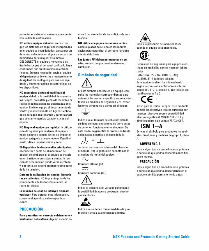
Símbolos de seguridad
Si este símbolo aparece en un equipo, con-sulte los manuales correspondientes para obtener información específica sobre adver-tencias o medidas de seguridad y así evitar lesiones personales o daños en el equipo.
Indica que el terminal de cableado aislado se debe conectar a una toma de tierra antes de poner en funcionamiento el equipo. De este modo, se garantiza la protección frente a descargas eléctricas en caso de fallo.
Terminal de conexión a tierra del chasis o armadura. Por lo general se conecta con la armadura de metal del equipo.
Corriente alterna (CA).
Corriente continua (CC).
Indica la presencia de voltajes peligrosos y la posibilidad de que se produzcan descar-gas eléctricas.
Indica que se deben tomar medidas de pro-tección frente a la electricidad estática.
Indica la presencia de radiación láser cuando el equipo está encendido.
Requisitos de seguridad para equipos eléc-tricos de medición, control y uso en labora-torios CAN/CSA C22.2 No. 1010.1 (1993) UL 3101, 3111 (primera edición) Este equipo también ha sido evaluado según la comisión electrotécnica interna-cional, IEC 61010, edición 1, que incluye las rectificaciones 1 y 2.
Aviso para la Unión Europea: este producto cumple las directivas legales europeas per-tinentes: directiva sobre compatibilidad electromagnética (EMC) 89/336/CEE y directiva sobre bajo voltaje 73/23/CEE.
Éste es el símbolo para productos industri-ales, científicos y médicos de grupo 1, clase A.
ADVERTENCIA
Indica algún tipo de procedimiento, práctica o condición que podría causar lesiones físi-cas o muerte.
PRECAUCIÓN
Indica algún tipo de procedimiento, práctica o condición que podría causar daños en el equipo o pérdida permanente de datos.
o
ISM 1—A
RT900UserGuide.book Page 8 Monday, January 8, 2007 5:47 PM
N2X Packets and Protocols Getting Started Guide 9
CertificazionePer informazioni specifiche sulla conformità alle disposizioni di legge, fare riferimento alla Dichiarazione di Conformità (Numero parte E7900-91300).
Agilent Technologies certifica che il pro-dotto è conforme alle specifiche pubblicate al momento dell'uscita dalla fabbrica. Agi-lent Technologies certifica inoltre che le misure di calibrazione sono da attribuire all'Istituto Nazionale Statunitense per gli Standard e la Tecnologia nella misura con-sentita dal servizio di calibrazione di tale organizzazione, e al servizio di calibrazione di altri membri dell'Organizzazione Interna-zionale per gli Standard.
Informazioni aggiuntive relative ad apparecchiature di misurazione e collaudoPer garantire il rispetto delle norme EMC, utilizzare i cavi forniti o consigliati per tutte le connessioni appropriate. In alternativa, l'utente deve assicurare il rispetto dei limiti per l'inferenza radiofonica in condizioni operative, entro i confini della propria sede.
AVVERTENZELe seguenti norme di sicurezza generali devono essere osservate durante tutte le fasi di funzionamento, utilizzo e riparazione del presente prodotto. La mancata osser-vanza di tali precauzioni, o di specifiche avvertenze contenute nel presente manu-ale, viola gli standard di sicurezza relativi alla progettazione, alla realizzazione e all'utilizzo designato del prodotto. Agilent Technologies declina qualsiasi responsabil-ità per la mancata osservanza di tali requi-siti da parte del cliente.
Messa a terra dell'apparecchiatura: per sicurezza, le apparecchiature di Classe 1 (dotate di un terminale di terra) devono essere fornite di messa a terra di sicurezza senza soluzione di continuità dalla princi-pale fonte di corrente ai terminali cablati d'ingresso del prodotto o al cavo di alimen-
tazione fornito. Prima di azionare l'apparec-chiatura, cautelarsi contro eventuali scosse elettriche in caso di guasto, utilizzando sempre il cavo di alimentazione a tre con-duttori fornito in dotazione per collegare l'apparecchiatura ad una presa di corrente con messa a terra.
NON utilizzare in ambienti pericolosi: non utilizzare il prodotto in ambienti esplosivi o in presenza di gas infiammabili o di fumo. Questo prodotto è esclusivamente per uso interno.
NON utilizzare fusibili riparati o supporti di fusibili cortocircuitati: per assicurare una protezione continua contro eventuali incendi, sostituire i fusibili di linea solo con fusibili della stessa tensione, potenza e tipo di corrente.
Tenere lontano dai circuiti sotto tensione: le coperture o gli schermi dell'apparecchia-tura non devono essere rimossi dal person-ale di servizio. Le procedure che implicano la rimozione di coperture e schermi devono essere eseguite esclusivamente da person-ale di assistenza qualificato. In determinate condizioni, valori di tensione pericolosi pos-sono essere raggiunti anche ad apparecchi-atura spenta. Per evitare scosse elettriche, NON eseguire procedure che comportano la rimozione di coperture o schermi se non si dispone dell'autorizzazione necessaria.
NON azionare apparecchiature danneg-giate: qualora si ritenga possibile che le car-atteristiche di sicurezza del prodotto si siano deteriorate a causa di danni fisici, eccessiva umidità o per qualsiasi altra ragione, SCOLLEGARE L'ALIMENTAZIONE e non utilizzare il prodotto finché il person-ale di assistenza qualificato non avrà accer-tato condizioni sicure di utilizzo. Se necessario, restituire il prodotto all'ufficio vendite e assistenza di Agilent Technologies per usufruire del servizio di assistenza e riparazione e garantire il mantenimento delle caratteristiche di sicurezza.
NON sostituire parti né modificare l'appar-ecchiatura: per prevenire ulteriori rischi, non installare parti sostitutive né apportare modifiche al prodotto senza previa autoriz-zazione. Restituire il prodotto all'ufficio ven-
dite e assistenza di Agilent Technologies per usufruire del servizio di assistenza e riparazione e garantire il mantenimento delle caratteristiche di sicurezza.
NON utilizzare liquidi per la pulizia: in caso contrario, l'utilizzo dell'apparecchiatura potrebbe diventare pericoloso. Spegnere l'apparecchio e scollegare il cavo di alimen-tazione prima di pulire il prodotto. Utilizzare un panno morbido e asciutto.
Il dispositivo di disconnessione principale è il connettore/cavo di alimentazione dell'apparecchio quando il telaio viene uti-lizzato da solo; tuttavia, se installato in un rack o in un sistema, il dispositivo di discon-nessione potrebbe venire danneggiato e deve essere considerato parte dell'instal-lazione.
Le schede potrebbero surriscaldarsi durante l'utilizzo. Quando una scheda viene rimossa dal telaio, NON toccarne i compo-nenti.
Può contenere dispositivi laser. Consultare l'appendice delle specifiche per ulteriori informazioni.
MISURE PRECAUZIONALIPer assicurare raffreddamento e ventilazi-one adeguati, lasciare un'apertura di almeno 50 mm (2 pollici) intorno ad ogni foro della ventola.
NON azionare con slot vuoti: riempire tutti gli slot vuoti con piastre di spegnimento per assicurare un funzionamento corretto del telaio.
Tutte le guarnizioni RFI devono rimanere al loro posto. Sostituire eventuali guarnizioni danneggiate.
Simboli di sicurezza
Se un prodotto è contrassegnato da questo simbolo, fare riferimento ai manuali per informazioni specifiche su avvertenze e mis-
RT900UserGuide.book Page 9 Monday, January 8, 2007 5:47 PM
10 N2X Packets and Protocols Getting Started Guide
ure precauzionali, al fine di evitare infortuni alle persone o danni al prodotto.
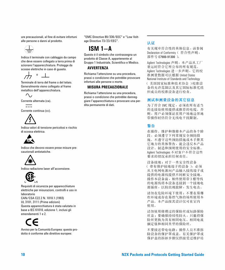
Indica il terminale con cablaggio da campo che deve essere collegato a terra prima di azionare l'apparecchiatura. Protegge da scosse elettriche in caso di guasto.
Terminale di terra del frame o del telaio. Generalmente viene collegato al frame metallico dell'apparecchiatura.
Corrente alternata (ca).
Corrente continua (cc).
Indica valori di tensione pericolosi e rischio di scossa elettrica.
Indica che devono essere prese misure pre-cauzionali antistatiche.
Indica radiazione laser all'accensione.
Requisiti di sicurezza per apparecchiature elettriche per misurazioni, controlli e uso in laboratorio CAN/CSA C22.2 N. 1010.1 (1993) UL 3101, 3111 (Prime edizioni) Questa apparecchiatura è stata valutata in base a IEC 61010, edizione 1, inclusi gli emendamenti 1 e 2.
Avviso per la Comunità Europea: questo pro-dotto è conforme alle direttive europee:
"EMC Directive 89/336/EEC" e "Low Volt-age Directive 73/23/EEC".
Questo è il simbolo che contrassegna un prodotto di Classe A, appartenente al Gruppo 1 Industriale, Scientifico e Medico.
AVVERTENZA
Richiama l'attenzione su una procedura, prassi o condizione che potrebbe provocare infortuni alle persone o morte.
MISURA PRECAUZIONALE
Richiama l'attenzione su una procedura, prassi o condizione che potrebbe danneg-giare l'apparecchiatura o provocare una per-dita permanente di dati.
认证
有关规章符合性的具体信息,请参阅
Declaration of Conformity (符合性声明,部件号 E7900-91300)。
Agilent Technologies 声明,本产品从工厂装运时符合它所公布的所有规范。Agilent Technologies 进一步声明,它的校准测量数据可以根据 United States National Institute of Standards and Technology
(美国国家标准和技术协会)校准设备的允许范围以及其它国际标准化组
织成员的校准设备进行检查。
测试和测量设备的其它信息
为了符合 EMC 规定,必须在所有适当
的连接处使用提供或推荐的电缆。否则,用户必须保证在用户场地边界地带操作时仍符合无线电干扰限制。
警告
在操作、维护和维修本产品的各个阶段,必须遵守下列常规安全预防措
施。不遵守这些预防措施或本手册其它地方的具体警告,就会违反本产品设计、制造和预期使用的安全标准。
Agilent Technologies 不对客户不符合这些要求的情况承担任何责任。
设备接地:对于一类安全性设备(带有保护接地端子的设备),必须从主电网电源向产品输入接线端子或提供的电源线提供不间断安全接地。
操作本设备前,始终使用带 3 根导线的电源线将本设备连接到一个接地电源插座,以防出现故障,发生电击。
请勿在危险环境下使用:不要在易爆炸环境或存在易燃气体的场所使用本
产品。本产品按其设计仅可在室内 使用。
请勿使用修理过的保险丝或短路保险
丝盒:要确保持续性防火,只能将保险丝更换为具有相同电压、相同电流额定值和相同类型的保险丝。
不要接近带电电路:操作人员不准拆除设备的保护罩或盖。有关保护罩或
保护盖的拆卸步骤仅供接受过维护培
o
ISM 1—A
RT900UserGuide.book Page 10 Monday, January 8, 2007 5:47 PM
N2X Packets and Protocols Getting Started Guide 11
训的人员使用。在某些情况下,即使关闭设备电源,设备仍存在危险电压。为了防止电击危险,如果您不是合格人员,请勿执行有关保护罩或保
护盖的拆卸步骤。
请勿操作损坏的设备:只要本产品内
置的安全保护功能部件因物理损坏、过于潮湿或任何其它原因可能受损,请断开电源,只有经受过维护培训的
人员检查保证可以进行安全操作时方可使用。如果需要,请将本产品退回
Agilent Technologies 销售和维护部门进行维护和修理,保证产品的安全功能部
件正常运作。
请勿使用替代部件或对设备进行修
改:由于会引发更多危险,请不要在本产品中使用替代部件或对其执行未经授权的任何修改。请将本产品退回
Agilent Technologies 销售和维护部门进行维护和修理,以保证产品功能正常。
请勿使用液体进行清洁:这样做会使设备无法安全使用。清洁前须关机并切断电源。请使用柔软的干布进行 清洁。
单独使用底架时,主断开设备是设备连接器 / 电源线。但装入机架或系统
时,断开设备可能受损,必须看作安装的一部分。
卡在使用期间会变热。从底架上拆卸卡时,请勿触摸卡上的任何组件。
可能包含激光设备。有关详细信息,
请参阅 Specifications (规范)附录。
小心
为了确保适当的冷却和通风,必须在所有通风孔周围至少留 2”(50 毫
米)的空隙。
在仍有空插槽的情况下请勿操作:请用盲板 填满空插槽,确保正确使用
底架。
所有 RFI 垫片必须安装就位。任何垫
片如果损坏,必须更换。
安全标志
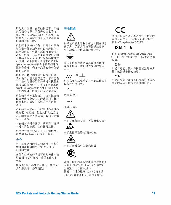
如果在产品上看到本标志,则必须参阅手册,了解具体的警告或注意事项,避免人身伤害或产品损坏。
表示使用本设备之前必须将现场接 线端子接地。防止出现故障时发生
电击。
机架或底架接地端子。一般连接到本设备的金属机架。
交流电 (ac)。
直流电 (dc)。
表示存在危险电压,可能发生电击。
表示应该采取静电预防措施。
表示打开时会产生激光辐射。
测量、控制和实验室用电气设备的安
全要求 CAN/CSA C22.2 No. 1010.1 (1993) UL 3101, 3111 (第一版) 同时,本设备根据 IEC 61010 第 1 版
(包括修订版 1 和 2)进行了评估。
欧洲共同体声明:本产品符合相关的欧洲法律指令:EMC Directive 89/336/EEC
和 Low Voltage Directive 73/23/EEC。
它是 Industrial, Scientific, and Medical Group 1
(工业、科学和医学组 1)A 类产品的标志。
警告
引起对可能导致人身伤害或致死的步骤、做法或条件的注意。
小心
引起对可能导致设备损坏或数据永久丢失的步骤、做法或条件的注意。
或
ISM 1—A
RT900UserGuide.book Page 11 Monday, January 8, 2007 5:47 PM

12 N2X Packets and Protocols Getting Started Guide
RT900UserGuide.book Page 12 Monday, January 8, 2007 5:47 PM
N2X Packets and Protocols Getting Started Guide 13
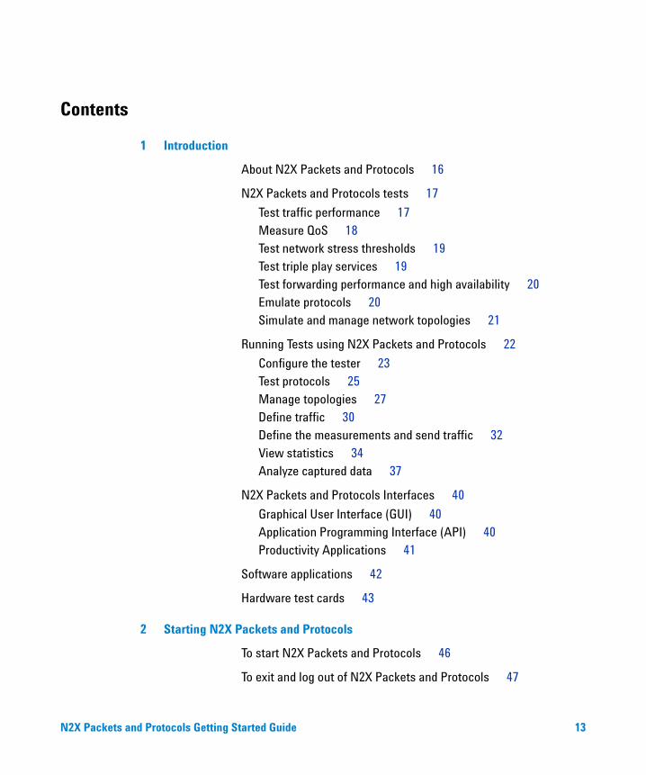
Contents
1 Introduction
About N2X Packets and Protocols 16
N2X Packets and Protocols tests 17
Test traffic performance 17Measure QoS 18Test network stress thresholds 19Test triple play services 19Test forwarding performance and high availability 20Emulate protocols 20Simulate and manage network topologies 21
Running Tests using N2X Packets and Protocols 22
Configure the tester 23Test protocols 25Manage topologies 27Define traffic 30Define the measurements and send traffic 32View statistics 34Analyze captured data 37
N2X Packets and Protocols Interfaces 40
Graphical User Interface (GUI) 40Application Programming Interface (API) 40Productivity Applications 41
Software applications 42
Hardware test cards 43
2 Starting N2X Packets and Protocols
To start N2X Packets and Protocols 46
To exit and log out of N2X Packets and Protocols 47
RT900UserGuide.book Page 13 Monday, January 8, 2007 5:47 PM
14 N2X Packets and Protocols Getting Started Guide
To get online help 48
3 Navigating N2X Packets and Protocols
N2X Packets and Protocols application 50
Menu bar 51Toolbar 52Setup bar 54Results bar 56Tools bar 57Setup — Traffic area 58Setup — Capture area 60Setup — Topology area 62Setup — Emulation area 64Setup — Video area 65Results — Realtime area 66Results — Capture Analysis area 69Applications area 72
A To contact us
To contact us 76
RT900UserGuide.book Page 14 Monday, January 8, 2007 5:47 PM
15
Agilent N2X Packets and ProtocolsGetting Started Guide
Agilent Technologies
1Introduction
About N2X Packets and Protocols 16
N2X Packets and Protocols tests 17
Running Tests using N2X Packets and Protocols 22
N2X Packets and Protocols Interfaces 40
Software applications 42
Hardware test cards 43
This chapter provides a high- level description of N2X Packets and Protocols. It describes how you can use N2X Packets and Protocols to run tests and what hardware and software components are available for your use.
RT900UserGuide.book Page 15 Monday, January 8, 2007 5:47 PM
16 N2X Packets and Protocols Getting Started Guide
1 Introduction
About N2X Packets and Protocols
N2X Packets and Protocols is a powerful and versatile test platform that addresses the evolving test needs of metro/edge platforms, core routers, and optical switches.
N2X Packets and Protocols provides Service Providers and Network Equipment Manufacturers with the industry's leading tools for wire- speed, multiport traffic generation and performance analysis, accelerating the deployment of current and emerging technologies. The N2X Packets and Protocols platform is a dense and powerful test system with cards providing great traffic stream and routing scalability.
N2X Packets and Protocols can:
• flexibly transmit and make real- time measurements on any packet format—from Ethernet frames through to GRE encapsulated packets, plus any user defined packet format.
• simulate a live network, stress a router's switching fabric, and verify that a router correctly prioritizes individual applications and services.
This unique integration enables N2X Packets and Protocols to scale from dual- port functional and performance testing to multi- port performance and stress testing configurations.
N2X consists of a combination of software applications and hardware interfaces. Regardless of the hardware you use, testing is controlled by the same easy- to- use management software running on a Windows PC.
For complete details about the different system components and possible configurations, refer to the N2X Packets and Protocols Installation and Administration Guide (E7901- 90004), which is included on the software CD and also installed with the software in this default location:
C:\Program Files\Agilent\N2X\RouterTester900 \<release>\doc\install.pdf
RT900UserGuide.book Page 16 Monday, January 8, 2007 5:47 PM
Introduction 1
N2X Packets and Protocols Getting Started Guide 17
N2X Packets and Protocols tests
N2X Packets and Protocols provides wire- speed, multi- port traffic generation, and performance analysis of today's networking devices, as well as comprehensive emulation of routing protocols. N2X Packets and Protocols allows you to:
• Test traffic performance
• Measure QoS
• Test network stress thresholds
• Test triple play services
• Test forwarding performance and high availability
• Emulate protocols
• Simulate and manage network topologies
Test traffic performance
N2X Packets and Protocols addresses the carrier class test challenges by providing:
• Internet- scale traffic generation—simulate traffic that tests routers under realistic conditions, from an aggregate of networks, and with traffic streams configured to reflect various mixtures of traffic
• performance measurements—real- time comparative performance measurements for different traffic types
• capture control—view packet decodes
With N2X Packets and Protocols you can:
• rapidly generate up to 32,768 traffic streams per port
• generate traffic with constant or bursty traffic profiles
• edit the field values of each packet header to perform a wide range of tests—for example, you can generate a mix of packet sizes and packet types, simulating an Internet distribution of packets
RT900UserGuide.book Page 17 Monday, January 8, 2007 5:47 PM
18 N2X Packets and Protocols Getting Started Guide
1 Introduction
• generate unique PDUs—for example, invalid packets for negative testing. Also, by modifying the Source Address or Destination Address fields in the packet header, you can generate unicast or multicast traffic. You can send an exact number of packets (for example, a single packet), or send a continuous stream of traffic.
You can generate traffic with the following characteristics:
• exact traffic paths—you can configure exact traffic paths through the SUT to create the conditions under which blocking within the switching fabric and contention for output ports can be observed
• many IP packets as if they came from and are destined to many networks
Measure QoS
With ISPs and vendors offering QoS guarantees, it is extremely important to ascertain a router’s ability to handle QoS before and during deployment.
Using N2X Packets and Protocols, you can determine if a router is able to deliver preferential quality of service (QoS) to particular flows or streams of traffic. The basic premise of quality of service is that in the presence of congestion, packets from a lower priority stream will be discarded before packets from a higher priority stream. The relative priority of a traffic stream is expressed within a packet’s Type of Service (TOS) field, or Differentiated Service Codepoint (DSCP) field. Other QoS mechanisms can prioritize packets based on other fields, such as the source/destination address, TCP port numbers, or HTTP URL.
N2X Packets and Protocols allows you to mimic complex traffic profiles that have different service classes and service types, by generating multiple streams of IP packets, each with different packet lengths, profiles, and priorities. You can then test if high priority flows have better throughput, latency, and loss behavior than ‘best effort’ flows.
RT900UserGuide.book Page 18 Monday, January 8, 2007 5:47 PM
Introduction 1
N2X Packets and Protocols Getting Started Guide 19
Test network stress thresholds
Using N2X Packets and Protocols, you can test how well the SUT handles different stress conditions, such as:
• many short packets, a mix of long and short packets sent simultaneously, long packet bursts against constant background traffic
• packets oversubscribed to a SUT queue, back- to- back packets or bursts
• packets of incrementing lengths or with random payload contents
• packets sent to specific unicast or multicast IP addresses
• errored data
Test triple play services
You can test how well a device or network forwards IPTV traffic in the presence of Internet and voice traffic. You can:
• simulate IPTV service providers offering broadcast TV, Pay- Per-View, and Video- on- Demand channels
• simulate 512 channels per test port
• generate actual MPEG video using Agilent- provided clips
• customize the video transmission to test:• MPEG- 2 or MPEG- 4 Part 10 (H.264) encoding• Standard Definition or High Definition format• a UDP or RTP/UDP protocol stack
• set the transmit rate for each channel to simulate different channel content (for example, sports or news)
• simulate thousands of IPTV subscribers using triple play (TV, phone, Internet) services
• objectively measure subscriber QoE using the Media Delivery Index (MDI)
• subjectively characterize video quality by capturing and playing back received video through a media player
• view N2X- generated video traffic on qualified Set- Top Boxes
RT900UserGuide.book Page 19 Monday, January 8, 2007 5:47 PM

20 N2X Packets and Protocols Getting Started Guide
1 Introduction
Test forwarding performance and high availability
You can test the router’s performance capabilities. You can test the router’s ability to handle millions of packets per second, from many interfaces, over many routes. You can measure performance characteristics such as: packet throughput, latency, and loss. You can also verify high availability and non- stop forwarding through graceful restart, fast reroute, and make- before- break tests.
Emulate protocols
You can simulate the functions of many protocols to verify that routers function as they should. You can simulate real- world Internet topologies in the lab by subjecting routers to dynamic protocol interactions.
Routing protocols:• BGP- 4, BGP- 4+• OSPFv2, OSPFv3• IS- ISv4, IS- ISv6• RIP, RIPng• LMP• LACP
Signaling protocols:• RSVP• LDP
Multicast protocols:• PIMv4• IGMPv2, IGMPv3• MLDv1, MLDv2• MSDP (IPv4)
Access protocols:• PPPoE, PPPoA, PPPoEoA, L2TP (PPPoL2TP)• DHCPv4, DHCPv6
You can design your own protocol tests or use predefined conformance test suites. For details about these test suites, see “Productivity Applications" on page 41.
RT900UserGuide.book Page 20 Monday, January 8, 2007 5:47 PM
Introduction 1
N2X Packets and Protocols Getting Started Guide 21
Simulate and manage network topologies
Using a combination of the individual protocol capabilities and the topology functionality, you can define a simulated network that matches your test requirements.
The topology testing functionality includes:
• Layer 2 MPLS VPN topology testing functionality:
• VPLS—Simulate a VPLS network topology that tests for VPLS scalability and flexibility. VPLS is an emerging technology for transparently connecting corporate LANs over the Internet so they appear and behave to customers like a single bridged Ethernet LAN. However, VPLS adds a new level of complexity to a PE routers' control plane and packet processing demands. Besides functioning as an MPLS Label Edge Router (LER) that provisions LSP tunnels and pushes/pops labels, the PE must serve as an Ethernet bridge, with all the learning, filtering, forwarding, and flooding requirements this entails. It must also implement the necessary LDP signaling extensions required by VPLS.
• L2oMPLS—Simulate a large core MPLS network with many thousands of point- to- point Layer 2 connections (virtual circuits) tunneled across it. This enables you to test router performance including Martini encapsulations for Ethernet, Frame Relay, and ATM.
• Layer 3 BGP- 4 MPLS VPNs—a mechanism by which service providers can use their IP backbones to provide VPN services to customers. RFC- 2547bis VPNs are also known as BGP- MPLS VPNs because the Border Gateway Protocol (BGP) is used to distribute VPN routing information across the provider’s backbone, and MPLS is used to establish virtual circuits and to forward VPN traffic across the backbone to remote VPN sites. Using N2X Packets and Protocols you can simulate Layer 3 BGP- 4 MPLS VPNs.
RT900UserGuide.book Page 21 Monday, January 8, 2007 5:47 PM
22 N2X Packets and Protocols Getting Started Guide
1 Introduction
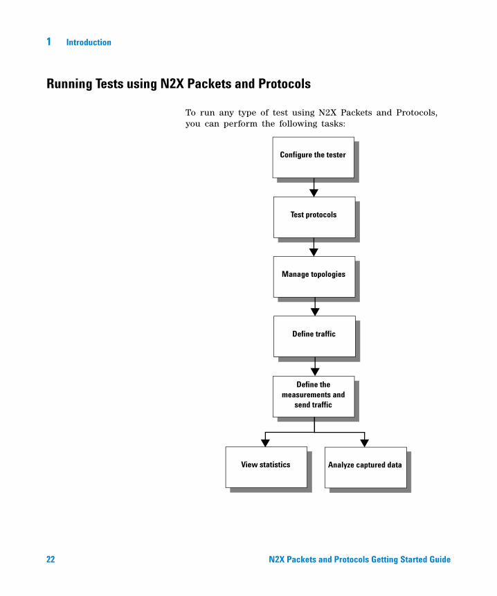
Running Tests using N2X Packets and Protocols
To run any type of test using N2X Packets and Protocols, you can perform the following tasks:
Test protocols
Configure the tester
Manage topologies
Define traffic
View statistics Analyze captured data
Define the measurements and
send traffic
RT900UserGuide.book Page 22 Monday, January 8, 2007 5:47 PM
Introduction 1
N2X Packets and Protocols Getting Started Guide 23
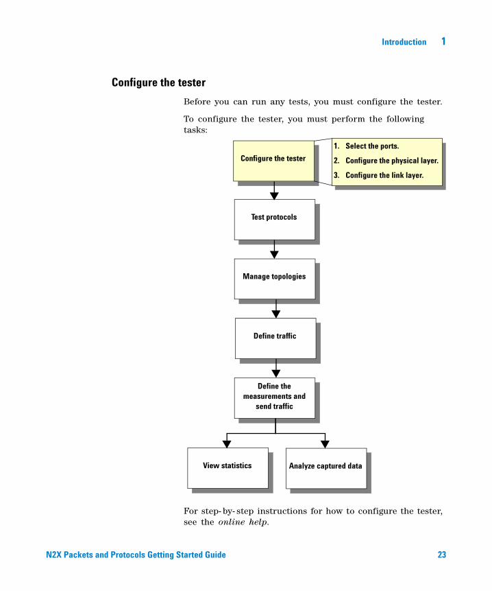
Configure the tester
Before you can run any tests, you must configure the tester.
To configure the tester, you must perform the following tasks:
For step- by- step instructions for how to configure the tester, see the online help.
1. Select the ports.
2. Configure the physical layer.
3. Configure the link layer.
Test protocols
Configure the tester
Manage topologies
Define traffic
View statistics Analyze captured data
Define the measurements and
send traffic
RT900UserGuide.book Page 23 Monday, January 8, 2007 5:47 PM
24 N2X Packets and Protocols Getting Started Guide
1 Introduction
Select the ports
You must select the test port(s) you want to use in this test session. If you are creating a new test session, you will be prompted for this selection when you first start N2X Packets and Protocols.
Configure the physical layer
Ensure the SONET/SDH, Ethernet/PCS, and VSR settings in the tester match those of the SUT. If you are using the tri- rate 10/100/1000 Ethernet test ports, the RJ45 connector is used by default. Select the GBIC or SFP connector as needed.
Optical test ports have their lasers turned on by default. If you have temporarily turned them off, turn them on again.
Configure the link layer
Configuring the link layer for:
• Ethernet—involves setting IP addresses, resolving SUT MAC addresses, and specifying the framing and 10/100, GbE, or 10GbE parameters for each port. You can configure the link layer for:
• IPv4 addresses
• IPv6 addresses
Note: If you are testing only at Layer 2, you do not need to configure the IP addresses.
• POS—involves configuring the PPP links, setting IP addresses, and selecting the encapsulation method.
• ATM—involves configuring the ATM framing and PDU encapsulation. You also need to define the PVCs (that is, the VPI/VCIs) that require real- time reassembly of ATM cells into AAL- 5 frames (for protocol emulations, statistics, and capture), and set the IP addresses used by higher- layer peers in protocol emulations.
• Frame Relay—involves configuring the framing, encapsulation, and PVCs (that is, DLCIs), and LMI operation.
RT900UserGuide.book Page 24 Monday, January 8, 2007 5:47 PM
Introduction 1
N2X Packets and Protocols Getting Started Guide 25
Test protocols
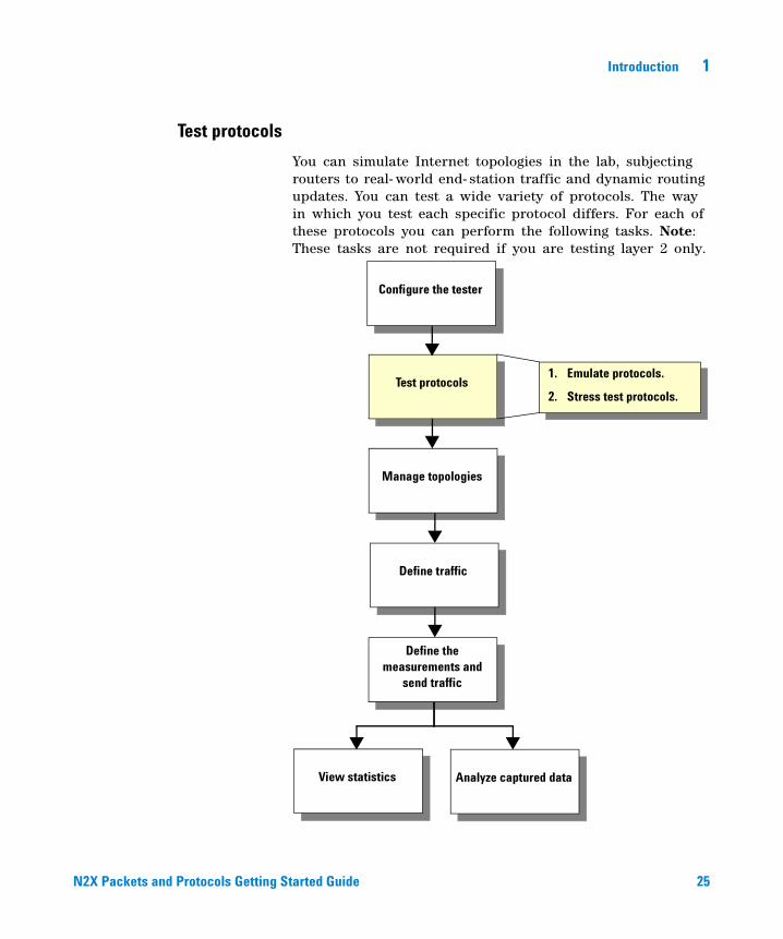
You can simulate Internet topologies in the lab, subjecting routers to real- world end- station traffic and dynamic routing updates. You can test a wide variety of protocols. The way in which you test each specific protocol differs. For each of these protocols you can perform the following tasks. Note: These tasks are not required if you are testing layer 2 only.
Test protocols
Configure the tester
1. Emulate protocols.
2. Stress test protocols.
Manage topologies
Define traffic
View statistics Analyze captured data
Define the measurements and
send traffic
RT900UserGuide.book Page 25 Monday, January 8, 2007 5:47 PM
26 N2X Packets and Protocols Getting Started Guide
1 Introduction
For step- by- step instructions for how to test protocols, see the online help.
Emulate protocols
N2X Packets and Protocols allows you to simulate the functions of a variety of protocols in order to test whether or not routers are implementing them as they should. The way in which you emulate each protocol differs. The high- level steps to emulate a protocol are:
• define the emulation—define the sessions, routes, or hosts as appropriate for the protocol.
• establish a connection/session—initiate routing emulation across all test ports.
• send protocol messages—send specific messages to test the protocol. The type of message depends on the protocol. For example, to test:
• OSPF, you send messages to advertise and withdraw a topology
• LMP, you send messages to renegotiate the Hello configuration
• MSDP, you send messages to advertise or cancel (S,G) memberships
• simulate protocol events—initiate events such as node or link failures to test fault recovery. For example, to test:
• graceful restart, you can close a routing session’s underlying TCP connection (to simulate a restarter) or provide non- stop forwarding (to simulate a helper)
• fast reroute, you can turn off a transmit laser on a link
• make- before- break, you can automatically or manually invoke the make- before- break process
• monitor the effect of the messages or events on the router—for example:
• measure the effect on traffic forwarding
• calculate convergence times
RT900UserGuide.book Page 26 Monday, January 8, 2007 5:47 PM
Introduction 1
N2X Packets and Protocols Getting Started Guide 27
Stress test protocols
Stress testing a router or a network is critical to establishing whether a router or network is able to sustain the loads expected when deployed. Stress testing the SUT entails sending the SUT large numbers of route updates and verifying its correct operation under stress.
For high stress purposes, multiple cards and chassis’ can be connected through a single hub to the SUT’s LAN interface allowing significant scaling capability.
Manage topologies
Using N2X Packets and Protocols you can simulate and manage L2 MPLS VPN network topologies.
To set up the topology, you configure:
• PE routers
• local and remote VPLS sites or L2oMPLS circuits
After setting up your topology, you can create a traffic mesh. This enables you to create multiple stream groups and specify how the traffic is routed from sources to destinations. Stream groups are automatically generated to facilitate traffic definition.
Common L2 MPLS VPN topology testing examples include:
• To test the VPLS MAC FIB table size
• To test VPLS unicast and flooding forwarding performance
• To verify spanning tree B- PDUs over VPLS
• To test how many VPLS sites your system supports
• To test how many VCs can be set up
• To set up a L2oMPLS (ATM, Frame Relay, or Ethernet) test topology
The steps involved in each of these examples are described in the online help.
RT900UserGuide.book Page 27 Monday, January 8, 2007 5:47 PM
28 N2X Packets and Protocols Getting Started Guide
1 Introduction
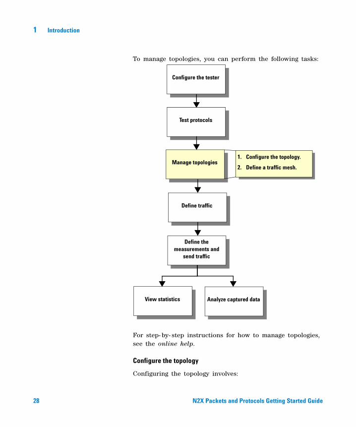
To manage topologies, you can perform the following tasks:
For step- by- step instructions for how to manage topologies, see the online help.
Configure the topology
Configuring the topology involves:
Configure the tester
Test protocols
Manage topologies
Define traffic
View statistics Analyze captured data
Define the measurements and
send traffic
1. Configure the topology.
2. Define a traffic mesh.
RT900UserGuide.book Page 28 Monday, January 8, 2007 5:47 PM
Introduction 1
N2X Packets and Protocols Getting Started Guide 29
• defining PE routers—On the provider side of a VPN network, remote PE routers function like Label Edge Routers (LERs) with a full mesh of MPLS Label Switched Paths (LSPs) connecting all PE routers. LDP or RSVP- TE is used to set up pairs of LSPs in each direction. Each PE router is configured to establish a targeted LDP session (T- LDP) with every other PE in the network. This targeted LDP session is used to establish virtual circuits (called VC LSPs) between each pair of customer sites in the VPN. When adding PE routers, you can select from routers in an advertised OSPF or IS- IS topology.
• creating local and remote VPLS sites—You can simulate a VPLS network consisting of multiple:
• local sites per access port
• remote VPLS sites per PE router
When setting up VPLS sites you can create multiple individual sites or, to create a large number of VPLS sites at the same time, you can create a pool of VPLS sites.
• creating L2oMPLS virtual circuits (ATM, Frame Relay, or Ethernet) simulating local and remote CEs. You can create thousands of virtual circuits by specifying minimal circuit attributes.
Define a traffic mesh
You can create and maintain a mesh of traffic. A traffic mesh defines how traffic is routed from sources, through the SUT, to destinations. The traffic mesh also defines the traffic distribution and orientation.
RT900UserGuide.book Page 29 Monday, January 8, 2007 5:47 PM
30 N2X Packets and Protocols Getting Started Guide
1 Introduction
Define traffic
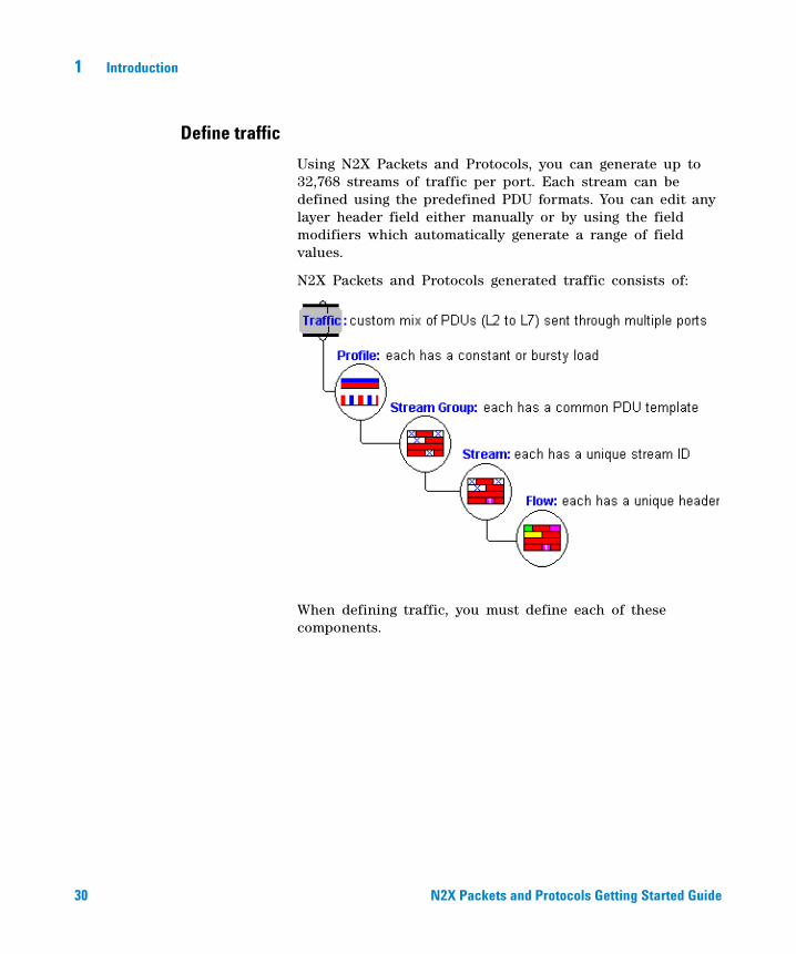
Using N2X Packets and Protocols, you can generate up to 32,768 streams of traffic per port. Each stream can be defined using the predefined PDU formats. You can edit any layer header field either manually or by using the field modifiers which automatically generate a range of field values.
N2X Packets and Protocols generated traffic consists of:
When defining traffic, you must define each of these components.
RT900UserGuide.book Page 30 Monday, January 8, 2007 5:47 PM
Introduction 1
N2X Packets and Protocols Getting Started Guide 31
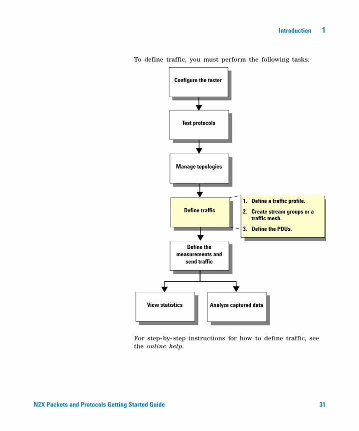
To define traffic, you must perform the following tasks:
For step- by- step instructions for how to define traffic, see the online help.
Test protocols
Configure the tester
Manage topologies
Define traffic
View statistics Analyze captured data
Define the measurements and
send traffic
1. Define a traffic profile.
2. Create stream groups or a traffic mesh.
3. Define the PDUs.
RT900UserGuide.book Page 31 Monday, January 8, 2007 5:47 PM
32 N2X Packets and Protocols Getting Started Guide
1 Introduction
Define a traffic profile
You can define either constant or bursty traffic profiles, and specify the traffic load to transmit. You also specify whether to transmit the traffic:
• continuously—transmit the defined traffic continuously until the traffic is manually stopped
• single- shot—transmit the defined traffic once only
Create a traffic stream group
Define the packet/frame lengths and select the expected destination port(s) for stream- level statistics.
Create a traffic mesh
A traffic mesh defines how traffic is routed from sources, through the SUT, to destinations. The traffic mesh also defines the traffic distribution and orientation.
When you create a traffic mesh, stream groups and profiles are automatically created.
Define the PDUs
Specify the values for each field in the packet header (for example, source/destination address, ToS). You can use field modifiers to rapidly vary the values of header fields. to generate unique streams to measure performance.
Define the measurements and send traffic
Before you send traffic, you select the statistics you want to display in real- time. You can also select the statistics after you have started generating traffic, however, the statistics will apply only to the traffic sent after you select the statistics.
RT900UserGuide.book Page 32 Monday, January 8, 2007 5:47 PM
Introduction 1
N2X Packets and Protocols Getting Started Guide 33
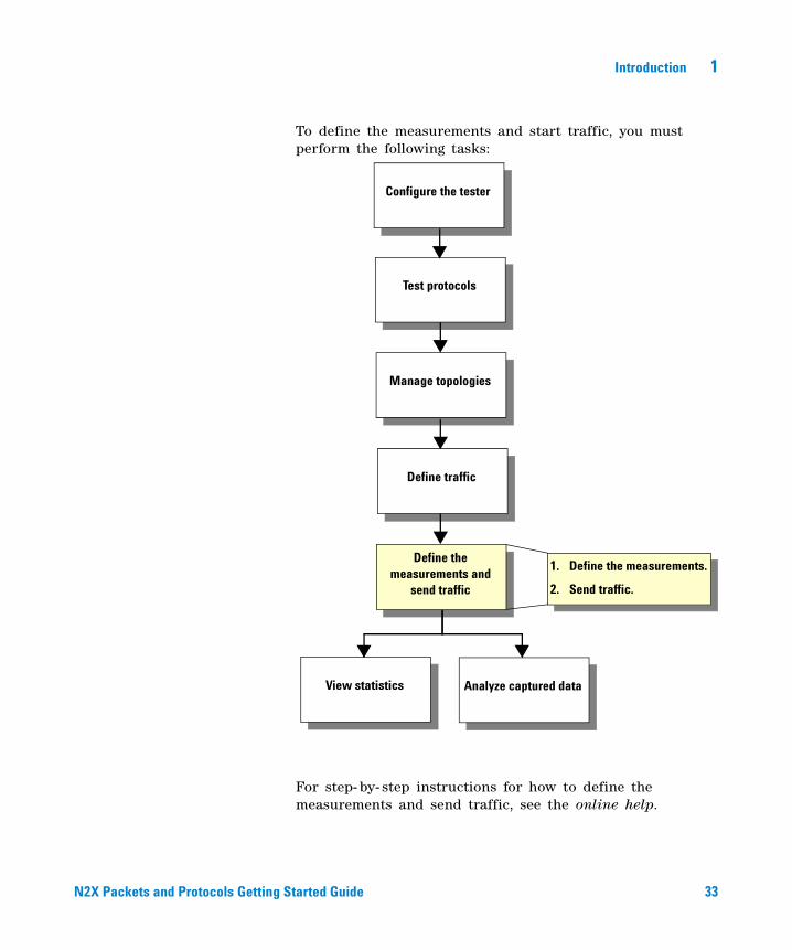
To define the measurements and start traffic, you must perform the following tasks:
For step- by- step instructions for how to define the measurements and send traffic, see the online help.
Test protocols
Configure the tester
Manage topologies
1. Define the measurements.
2. Send traffic.
Define traffic
View statistics Analyze captured data
Define the measurements and
send traffic
RT900UserGuide.book Page 33 Monday, January 8, 2007 5:47 PM

34 N2X Packets and Protocols Getting Started Guide
1 Introduction
Define the measurements
You can monitor the SUT's packet throughput, latency, loss, and errors. Statistics are provided per test port, per traffic stream (up to 32,000 streams per port depending on the port type and statistics mode), and per field (currently only for VLAN ID field). This allows you to easily compare different traffic streams to identify the router’s ability to manage different traffic classes.
You can select many different statistics and monitor their results in real- time, across small sampling intervals. After you stop a test, the tester continues measuring statistics for a specified trickle time, so that in- transit IP packets can reach their destinations and be counted in the statistics.
Send traffic
After defining measurements, you can then transmit the traffic. While transmitting traffic, you can dynamically change the traffic load for any stream group to monitor its effect on router performance.
View statistics
As the SUT routes the simulated traffic through its interfaces, the test ports measure SUT performance in real- time.
RT900UserGuide.book Page 34 Monday, January 8, 2007 5:47 PM
Introduction 1
N2X Packets and Protocols Getting Started Guide 35
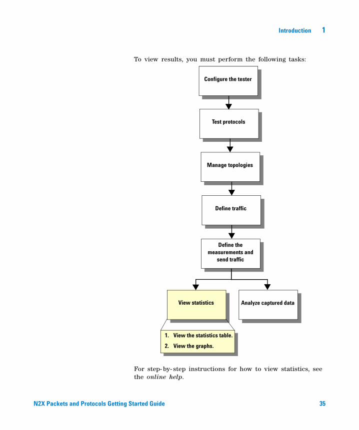
To view results, you must perform the following tasks:
For step- by- step instructions for how to view statistics, see the online help.
Test protocols
Configure the tester
Manage topologies
1. View the statistics table.
2. View the graphs.
Define traffic
View statistics Analyze captured data
Define the measurements and
send traffic
RT900UserGuide.book Page 35 Monday, January 8, 2007 5:47 PM
36 N2X Packets and Protocols Getting Started Guide
1 Introduction
View the statistics table
You can view the selected statistics per port, per stream, or per field (currently only VLAN ID field) as numerical values. These values are updated on the Graphical User Interface regularly.
You can also log statistics to a plain text file, in comma- separated values (CSV) format.
View the graphs
You can view results in a:
• bar graph—to compare up to 10 statistics side- by- side
• line graph—to track up to 10 statistics over time and detect trends
RT900UserGuide.book Page 36 Monday, January 8, 2007 5:47 PM

Introduction 1
N2X Packets and Protocols Getting Started Guide 37
Analyze captured data
To capture and analyze data, you can perform the following tasks:
1. Configure data capture.
2. Capture data
3. Analyze data.
4. View packet decode data.
Test protocols
Define traffic
View statistics Analyze captured data
Define the measurements and
send traffic
Configure the tester
Manage topologies
RT900UserGuide.book Page 37 Monday, January 8, 2007 5:47 PM
38 N2X Packets and Protocols Getting Started Guide
1 Introduction
For step- by- step instruction for how to capture and analyze data, see the online help.
Configure data capture
You can capture data from a single port or multiple ports.
You can specify the following on each port on which capture is enabled:
• triggers—define start capture and stop capture trigger actions. Triggers include valid packets, invalid packets, field value matches, and forwarding errors.
• filters—select filters to use when capturing data. Capture filters enable you to optimize the use of capture memory by specifying the characteristics of what packets you want stored or discarded.
Capture data
You can start capturing data after you have set up triggers and filters, and defined the buffer size required.
You can start the capture:
• manually
• on a trigger
You can stop a capture:
• manually
• when the buffer is full
• on a trigger
When the capture is complete you can save the data to a capture file.
Analyze data
Analyzing data provides a graphical representation of an entire capture buffer. You can select a point of interest, such as a spike in latency, and then drill down by re- analyzing the location around the selected point. You can continue to drill down until you have located a single packet of interest.
RT900UserGuide.book Page 38 Monday, January 8, 2007 5:47 PM
Introduction 1
N2X Packets and Protocols Getting Started Guide 39
View packet decode data
You can display a comprehensive protocol decode view of the captured data. A wide range of protocols are supported, including Layer 2, Layer 3, as well as routing protocols. You can view:
• a detailed protocol decode (text or tree view)
• a hexadecimal dump of the captured packet
• N2X Packets and Protocols test payload and capture overhead decodes
You can:
• decode captured data (entire Layer 2 frames).
• define the details you want to view. For example, in the PDU Summary List you can select to view the timestamp as relative, absolute, or interval, or select not to see it at all. You can also jump directly to a packet of interest.
• save packet data to a capture file.
RT900UserGuide.book Page 39 Monday, January 8, 2007 5:47 PM
40 N2X Packets and Protocols Getting Started Guide
1 Introduction
N2X Packets and Protocols Interfaces
N2X Packets and Protocols allows you to run tests using the:
• Graphical User Interface (GUI)
• Application Programming Interface (API)
• Productivity Applications
These software interfaces are used in conjunction with the hardware test cards described in “Hardware test cards” on page 43.
Graphical User Interface (GUI)
The tester provides a Windows- based Graphical User Interface (GUI). The GUI provides a visual way of entering information into the tester. The GUI also provides a visual way to monitor protocol emulations and statistics in real- time. See “N2X Packets and Protocols application” on page 50 for an overview of the GUI.
You can perform a wide variety of tests using the GUI. Step- by- step instructions for using the GUI are provided in the online help.
Application Programming Interface (API)
The API allows you to automate tests that:
• are too tedious or imprecise to do manually or repeatedly through the GUI
• integrate tests with larger test suites that access other test equipment and Systems Under Test (SUT)
• repeat tests for subsequent product builds
• regression test new versions or releases of products
There is no need to write scripts from scratch as there are sample scripts provided. The scripting language used is Tcl/Tk.
RT900UserGuide.book Page 40 Monday, January 8, 2007 5:47 PM
Introduction 1
N2X Packets and Protocols Getting Started Guide 41
Tcl/Tk scripting is best suited to coordinating the operation of protocols with other testing tasks such as traffic generation and statistics collection. For more information, see the N2X Packets and Protocols Tcl Programmer’s Guide or the N2X Packets and Protocols Online API Help.
Productivity Applications
N2X includes a rich set of automation tools designed to maximize your testing productivity.
There are three types of applications available:
• Productivity Applications
• Conformance test suites
• QuickTests
Productivity Applications
Productivity applications focus on validating the performance and scalability characteristics of next generation network infrastructure and services. These applications simplify complex test scenarios.
See the Productivity Application online help for usage details.
Conformance test suites
Conformance tests provide a variety of preconfigured test suites that you can run quickly and easily to assess your systems conformance to the applicable industry standards. N2X provides both protocol and functional conformance tests.
See the Conformance Test online help for usage details.
QuickTests
QuickTests provides a set of libraries and utilities that automate and simplify testing. Using QuickTest scripts, you can run a wide range of tests that comply with current benchmarking initiatives. You can run QuickTest from:
RT900UserGuide.book Page 41 Monday, January 8, 2007 5:47 PM

42 N2X Packets and Protocols Getting Started Guide
1 Introduction
• a standalone QuickTest browser—includes a script collection browser, a set of layered libraries, and a code generator which enable you to develop automated tests to meet your specific testing needs.
• the N2X Packets and Protocols Graphical User Interface—includes a script collection browser and a set of layered libraries.
See the QuickTest online help for usage details.
Software applications
N2X Packets and Protocols offers the following software applications:
• E7880B Packets (Traffic Generation)
• E7881B Packets and Protocols
• E7882A IPv4 Routing Emulation
• E7883A MPLS Signaling Emulation
• E7884A Layer 2 MPLS VPN Application
• E7885A IPv6 Routing Emulation
• E7886A Multicast Routing Emulation
• E7887A DHCP Emulation
• E7888A Access Protocol Emulation
• E7889A Optical Signaling Emulation
• E7896A DHCPv6 Emulation
• E7897A MLDv1, MLDv2
• E7898A DHCPv6 + MLDv1/v2 Bundle
• E7879A MPLS OAM
• E7877A IPTV Video Generation and Analysis
• N5582A LACP Emulation
Please contact your local Agilent sales representative for more information about any of these products.
RT900UserGuide.book Page 42 Monday, January 8, 2007 5:47 PM
Introduction 1
N2X Packets and Protocols Getting Started Guide 43
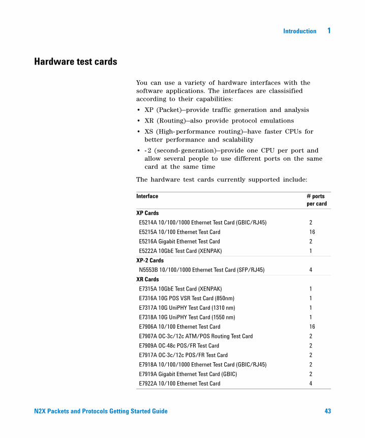
Hardware test cards
You can use a variety of hardware interfaces with the software applications. The interfaces are classisified according to their capabilities:
• XP (Packet)—provide traffic generation and analysis
• XR (Routing)—also provide protocol emulations
• XS (High- performance routing)—have faster CPUs for better performance and scalability
• - 2 (second- generation)—provide one CPU per port and allow several people to use different ports on the same card at the same time
The hardware test cards currently supported include:
Interface # ports per card
XP Cards
E5214A 10/100/1000 Ethernet Test Card (GBIC/RJ45) 2
E5215A 10/100 Ethernet Test Card 16
E5216A Gigabit Ethernet Test Card 2
E5222A 10GbE Test Card (XENPAK) 1
XP-2 Cards
N5553B 10/100/1000 Ethernet Test Card (SFP/RJ45) 4
XR Cards
E7315A 10GbE Test Card (XENPAK) 1
E7316A 10G POS VSR Test Card (850nm) 1
E7317A 10G UniPHY Test Card (1310 nm) 1
E7318A 10G UniPHY Test Card (1550 nm) 1
E7906A 10/100 Ethernet Test Card 16
E7907A OC-3c/12c ATM/POS Routing Test Card 2
E7909A OC-48c POS/FR Test Card 2
E7917A OC-3c/12c POS/FR Test Card 2
E7918A 10/100/1000 Ethernet Test Card (GBIC/RJ45) 2
E7919A Gigabit Ethernet Test Card (GBIC) 2
E7922A 10/100 Ethernet Test Card 4
RT900UserGuide.book Page 43 Monday, January 8, 2007 5:47 PM
44 N2X Packets and Protocols Getting Started Guide
1 Introduction
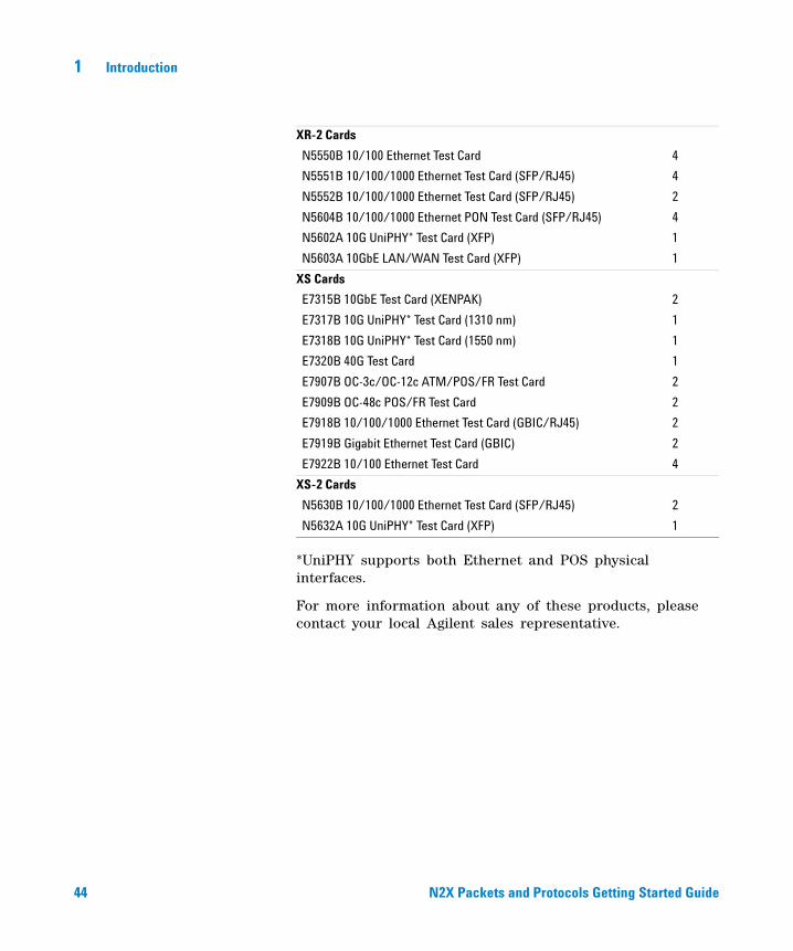
*UniPHY supports both Ethernet and POS physical interfaces.
For more information about any of these products, please contact your local Agilent sales representative.
XR-2 Cards
N5550B 10/100 Ethernet Test Card 4
N5551B 10/100/1000 Ethernet Test Card (SFP/RJ45) 4
N5552B 10/100/1000 Ethernet Test Card (SFP/RJ45) 2
N5604B 10/100/1000 Ethernet PON Test Card (SFP/RJ45) 4
N5602A 10G UniPHY* Test Card (XFP) 1
N5603A 10GbE LAN/WAN Test Card (XFP) 1
XS Cards
E7315B 10GbE Test Card (XENPAK) 2
E7317B 10G UniPHY* Test Card (1310 nm) 1
E7318B 10G UniPHY* Test Card (1550 nm) 1
E7320B 40G Test Card 1
E7907B OC-3c/OC-12c ATM/POS/FR Test Card 2
E7909B OC-48c POS/FR Test Card 2
E7918B 10/100/1000 Ethernet Test Card (GBIC/RJ45) 2
E7919B Gigabit Ethernet Test Card (GBIC) 2
E7922B 10/100 Ethernet Test Card 4
XS-2 Cards
N5630B 10/100/1000 Ethernet Test Card (SFP/RJ45) 2
N5632A 10G UniPHY* Test Card (XFP) 1
RT900UserGuide.book Page 44 Monday, January 8, 2007 5:47 PM

45
Agilent N2X Packets and ProtocolsGetting Started Guide
Agilent Technologies
2Starting N2X Packets and Protocols
To start N2X Packets and Protocols 46
To exit and log out of N2X Packets and Protocols 47
To get online help 48
Before you can start N2X Packets and Protocols, make sure you have set up your system as described in the N2X Packets and Protocols Installation and Administration Guide. Make sure you have the required licenses installed and the correct system version selected.
The Journal of Internet Test Methodologies includes the key tests necessary to verify and characterize the operational performance of core Internet routers. You can use this journal to help you implement your test strategy. The online help also provides a number of Application Notes that describe the steps required to perform some sample test scenarios.
The journal is available online at: www.agilent.com/comms/N2X.
RT900UserGuide.book Page 45 Monday, January 8, 2007 5:47 PM
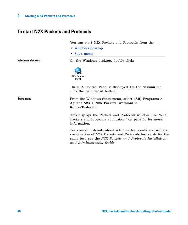
46 N2X Packets and Protocols Getting Started Guide
2 Starting N2X Packets and Protocols
To start N2X Packets and Protocols
You can start N2X Packets and Protocols from the:
• Windows desktop
• Start menu
This displays the Packets and Protocols window. See “N2X Packets and Protocols application” on page 50 for more information.
For complete details about selecting test cards and using a combination of N2X Packets and Protocols test cards for the same test, see the N2X Packets and Protocols Installation and Administration Guide.
Windows desktop On the Windows desktop, double- click:
The N2X Control Panel is displayed. On the Session tab, click the Launchpad button.
Start menu From the Windows Start menu, select (All) Programs > Agilent N2X > N2X Packets <version> > RouterTester900.
RT900UserGuide.book Page 46 Monday, January 8, 2007 5:47 PM
Starting N2X Packets and Protocols 2
N2X Packets and Protocols Getting Started Guide 47
To exit and log out of N2X Packets and Protocols
Before you turn off the PC, always shut down Windows. Wait for the message indicating that it’s safe to power down. There are two ways to power down:
• on the desktop, click Start > Shut Down
• on the Windows Security dialog box, click Shut Down
Exit application
On the N2X Packets and Protocols window, click Session > Exit. Select whether you want to save your current test configuration. Indicate whether to leave the test session running in the background.
Log out of Windows
On the desktop, click Start > Log Off Administrator. Confirm that you want to end your Windows session.Or Press Ctrl+Alt+Del. The Windows Security dialog box is displayed. Click Logoff and confirm that you want to end your Windows session.
RT900UserGuide.book Page 47 Monday, January 8, 2007 5:47 PM
48 N2X Packets and Protocols Getting Started Guide
2 Starting N2X Packets and Protocols
To get online help
The online help and guides are provided on both the
• N2X Packets and Protocols PC: C:\Program Files\Agilent\N2X\RouterTester900\<version>\doc
• N2X Packets and Protocols CD: \doc
Launch RT900Master.chm to see the GUI and API online help or .pdf files to see the guides. Launch RT900MasterApi.chm to see only the API online help.
Help menu The online help includes:
• Contents—Opens the N2X Packets and Protocols Help Table of Contents.
• Index—Opens the N2X Packets and Protocols Help keyword index.
• API—Opens the N2X Packets and Protocols API help.
• About Packets and Protocols—Displays information about the N2X Packets and Protocols version.
Dialog box and window help buttons
Provides context- sensitive details about the current dialog box and what to enter for each field.
Start menu Provides access to the same help accessed from the main Help Menu.
RT900UserGuide.book Page 48 Monday, January 8, 2007 5:47 PM
49
Agilent N2X Packets and ProtocolsGetting Started Guide
Agilent Technologies
3Navigating N2X Packets and Protocols
N2X Packets and Protocols application 50
This chapter describes:
• the different functional areas in the Graphical User Interface (GUI)
• how to navigate around the N2X Packets and Protocols GUI
RT900UserGuide.book Page 49 Monday, January 8, 2007 5:47 PM
50 N2X Packets and Protocols Getting Started Guide
3 Navigating N2X Packets and Protocols
N2X Packets and Protocols application
The Graphical User Interface (GUI) provides a visual way of entering information into the tester. You can access all of the N2X Packets and Protocols functions from the main Packets and Protocols window. This window comprises a number of areas which are used to perform different functions.
Setup — Traffic/Capture/Topology /Emulation/Video area
Menu bar
Tools bar
Toolbar
Setup bar
Results bar
Results — Realtime /Capture Analysis area
RT900UserGuide.book Page 50 Monday, January 8, 2007 5:47 PM
Navigating N2X Packets and Protocols 3
N2X Packets and Protocols Getting Started Guide 51
Menu bar
The menu bar provides access to the majority of N2X Packets and Protocols functions.
The following menus are provided:
• Session—open, save, reset, exit, or edit the properties of a test session.
• Edit—copy, paste, delete, or edit the properties of the selected item.
• View—select the information to display on the Packets and Protocols window and how you want it displayed.
• Actions—functions depend on the selected Setup area:• Traffic—add a new stream group, preview packet
details, move streams within a stream group, select which streams or stream groups to send, and start and stop sending traffic.
• Capture—specify how much data to capture, start and stop data capture, and open, close and save capture files. You can also display the capture data decode details and generate an analysis.
• Topology—add PE routers to a port, add VPLS sites to ports or PE routers, add L2oMPLS circuits to ports, enable and disable topology objects, and create a new traffic mesh.
• Emulation—add a protocol emulation, enable and disable emulations, initiate protocol actions.
• Video—add a video source, add a channel pool, preview transmitted video
• Results—select which measurements you want, and how you want them displayed.
• Tools—launch a Tcl or Wish shell to use the API, run a Ping test, display the Test Log or Message Log, display the Dashboard, or open the Pattern Library, Frame Matcher Library, or the Analysis Filter Library Editor.
• Help—display the N2X Packets and Protocols Help and version information.
RT900UserGuide.book Page 51 Monday, January 8, 2007 5:47 PM
52 N2X Packets and Protocols Getting Started Guide
3 Navigating N2X Packets and Protocols
Toolbar
The toolbar provides access to some of the N2X Packets and Protocols functions.
The icons are grouped by related functionality:
Session related icons:
Click ... To ...
open a saved test session.
save a test session.
View related icons:
Click ... To ...
display the Setup — Traffic/Capture/Topology area on the Packets and Protocols window.
display the Results area on the Packets and Protocols window.
display the Productivity Applications area on the Packets and Protocols window.
display each area tiled across the Packets and Protocols window.
display each area tiled down the Packets and Protocols window.
display the Options dialog box, which enables you to select how you want to display information on the Packets and Protocols window.
Traffic related icons:
Click ... To ...
display or edit the test ports currently in the session.
RT900UserGuide.book Page 52 Monday, January 8, 2007 5:47 PM
Navigating N2X Packets and Protocols 3
N2X Packets and Protocols Getting Started Guide 53
display or edit the test session properties.
Displays the duration for which traffic and measurements have been running.
start traffic and measurements. While the tester is preparing the test ports for traffic and measurements, the button is grayed out. While the tester is sending traffic and measuring statistics, the button alternates between a dark blue and light blue icon.
Capture related icons:
Click ... To ...
start capturing traffic. While the tester is preparing the test ports for capture, the button is grayed out. While the tester is capturing data, the button alternates between a dark red and light red icon.
Routing related icons:
Click ... To ...
start routing and signalling emulations. While the tester is preparing the test ports for routing and signalling, the button is grayed out. While the tester is emulating routing and signaling, the button alternates between a dark green and light green icon.
Help related icons:
Click ... To ...
display online help for N2X Packets and Protocols.
RT900UserGuide.book Page 53 Monday, January 8, 2007 5:47 PM
54 N2X Packets and Protocols Getting Started Guide
3 Navigating N2X Packets and Protocols
Setup bar
Use the Setup bar to select the test attributes you want to set up.
You can select:
• Traffic—to display the Setup — Traffic area in which you configure traffic. When you click this button, the following buttons are displayed (note that this is the default view and by default these buttons are available):
• Ports—select to display ports in the current test session and stream groups on the selected port.
• Meshes—select to display details of each traffic mesh in the current test session.
• Capture—to display the Setup — Capture area in which you configure capture and analyze captured data.
• Topology—to display the Setup — Topology area in which you configure the VPLS or L2oMPLS topologies. When you click this button, the following buttons are displayed:
• Summary—select to display all PE routers, VPLS sites, VPLS site pools, and L2oMPLS circuits associated with the selected port. VPLS sites, VPLS site pools, and L2oMPLS circuits are grouped within their PE router.
RT900UserGuide.book Page 54 Monday, January 8, 2007 5:47 PM

Navigating N2X Packets and Protocols 3
N2X Packets and Protocols Getting Started Guide 55
• PE—select to display all PE routers associated with the selected port.
• VPLS—select to display all local and remote VPLS sites and site pools associated with the selected port. VPLS sites and site pools are grouped within their PE router.
• L2oMPLS—select to display all local and remote L2oMPLS virtual circuits associated with the selected port. Remote L2oMPLS circuits are grouped within their PE router.
• Emulation—to display the Setup — Emulation area in which you configure and control protocol emulations.
• Video—to display the Setup — Video area in which you configure IPTV traffic sources and channels.
• Link Layer—to display the Link dialog box on which you configure the link layer protocols.
• Physical Layer—to display the Physical dialog box on which you configure the physical layer protocols.
RT900UserGuide.book Page 55 Monday, January 8, 2007 5:47 PM

56 N2X Packets and Protocols Getting Started Guide
3 Navigating N2X Packets and Protocols
Results bar
Use the Results bar to select how the results are displayed in the Results area.
You can select:
• Realtime—to display the Results — Realtime area (displayed by default). Use this area to view the realtime measurements (for example traffic measurements).
• Analysis—to display the Results — Capture Analysis area. Use this area to analyze captured data.
• Table—to display the results in numerical form in a table in the Results area.
• Graphs—to display the results as line or bar graphs in the Results area.
• Both—to display the results in both a table and graphs in the Results area (default).
RT900UserGuide.book Page 56 Monday, January 8, 2007 5:47 PM
Navigating N2X Packets and Protocols 3
N2X Packets and Protocols Getting Started Guide 57
Tools bar
Use the Tools bar to review the status of the tester.
You can select:
• Ping Test—to run a Ping test to verify IP- layer connectivity between the test ports connected to the SUT.
• Dashboard—to monitor the CPU and memory usage of test ports during a test. You can determine whether a test is approaching its resource limits or whether you can further increase the scale of the test.
• Test Log—to display a historical log of test events that have occurred since the start of the test.
RT900UserGuide.book Page 57 Monday, January 8, 2007 5:47 PM
58 N2X Packets and Protocols Getting Started Guide
3 Navigating N2X Packets and Protocols
Setup — Traffic area
Use the Setup — Traffic area to define and generate traffic. This area is displayed by default when you start N2X Packets and Protocols. If it is not displayed, click Traffic in the Setup bar.
The Setup—Traffic area contains the following panes:
• Ports pane—use this pane to select the tester port for which you want to define the traffic.
Ports pane
Details pane
RT900UserGuide.book Page 58 Monday, January 8, 2007 5:47 PM
Navigating N2X Packets and Protocols 3
N2X Packets and Protocols Getting Started Guide 59
• Details pane—use this pane to define the traffic that you want to generate.
You can double- click any item in these panes to display and edit the item’s properties. In addition, if you right- click a selected item, a menu is displayed providing access to traffic related functions.
The Setup — Traffic area has the following icons:
Refer to the online help for more information about how to define and generate traffic.
Click ... To ...
create a new stream group (displayed in the Details pane) or traffic mesh. Before creating certain traffic mesh types, ensure you have created the required topology elements. For example, when creating a L2oMPLS topology, you must have configured the PE routers and L2oMPLS circuits.
copy the selected stream group.
paste the selected stream group.
delete the selected stream group.
display the properties for the selected item: port, profile, or stream group.
(Available only when using the mesh view.)
update the stream groups by removing all stream groups in the mesh, and re- creating them to reflect the current state of the link layer address and route pools.
move the stream group up or down within the profile.
send the selected traffic profile once only.
move the slider bar to increase or decrease the intended transmit traffic load.
RT900UserGuide.book Page 59 Monday, January 8, 2007 5:47 PM
60 N2X Packets and Protocols Getting Started Guide
3 Navigating N2X Packets and Protocols
Setup — Capture area
Use the Setup — Capture area to capture data. This area is displayed when you click Capture in the Setup bar.
You can double- click any item in the list (port or capture file) to display decode details. In addition, if you right- click a selected item, a menu is displayed providing access to capture related functions.
The Setup — Capture area has the following icons:
Click ... To ...
display the capture properties for a port.
run a single shot capture (until the capture buffer is full or a stop trigger is activated).
RT900UserGuide.book Page 60 Monday, January 8, 2007 5:47 PM
Navigating N2X Packets and Protocols 3
N2X Packets and Protocols Getting Started Guide 61
Refer to the online help for more information about how to capture data.
run a cyclic capture (continuously capture data until you manually stop the capture or a stop trigger is activated).
to start capturing data based on selected triggers and filters.
open a capture file.
save captured data to a file.
display the capture decodes for the selected port or capture file.
display the Generate Analysis dialog box. Use this dialog box to generate an analysis with or without using an analysis filter. Use an analysis filter to enable you to define the packets you want to include in the analysis.
cancel the first queued request. Requests include:
• packet request—occurs when displaying capture source data in the Packet Decode dialog box
• analysis request—occurs when you request an analysis on a capture source
• distribution analysis request—occurs when you request distribution data from an analysis set
• save capture request—occurs when saving capture data to a capture file
RT900UserGuide.book Page 61 Monday, January 8, 2007 5:47 PM
62 N2X Packets and Protocols Getting Started Guide
3 Navigating N2X Packets and Protocols
Setup — Topology area
Use the Setup — Topology area to configure topologies. This area is displayed when you click Topology in the Setup bar.
The Setup —Topology area contains the following panes:
• Ports pane—use this pane to select the port to which you want to add a PE router, VPLS site (either an individual VPLS site or a pool of VPLS sites), or a L2oMPLS circuit.
• Details pane—use this pane to define and edit VPLS site details, L2oMPLS circuit details, and PE router details.
You can double- click any item in the list (port, VPLS site, VPLS site pool, L2oMPLS circuits, or PE router) to display the item’s properties. In addition, if you right- click a selected item, a menu is displayed providing access to topology related functions.
Details pane
Ports pane
RT900UserGuide.book Page 62 Monday, January 8, 2007 5:47 PM
Navigating N2X Packets and Protocols 3
N2X Packets and Protocols Getting Started Guide 63
The Setup — Topology area has the following icons:
Refer to the online help for more information about how to view results.
Click ... To ...
create a new topology element. The icon on the button indicates what you will create when you click the button (PE router by default). To select a different topology element, click the arrow and select the required topology element. You can select:
• PE Router—click to add a PE router to the selected port.
• VPLS Site—click to add a VPLS site or VPLS site pool to a port or PE router.
• L2oMPLS Circuits—click to add a L2oMPLS virtual circuit to a port.
Your selection will then become the default action of the New button and the icon will change to reflect this.
delete the selected topology element.
display the properties of your selection.
RT900UserGuide.book Page 63 Monday, January 8, 2007 5:47 PM
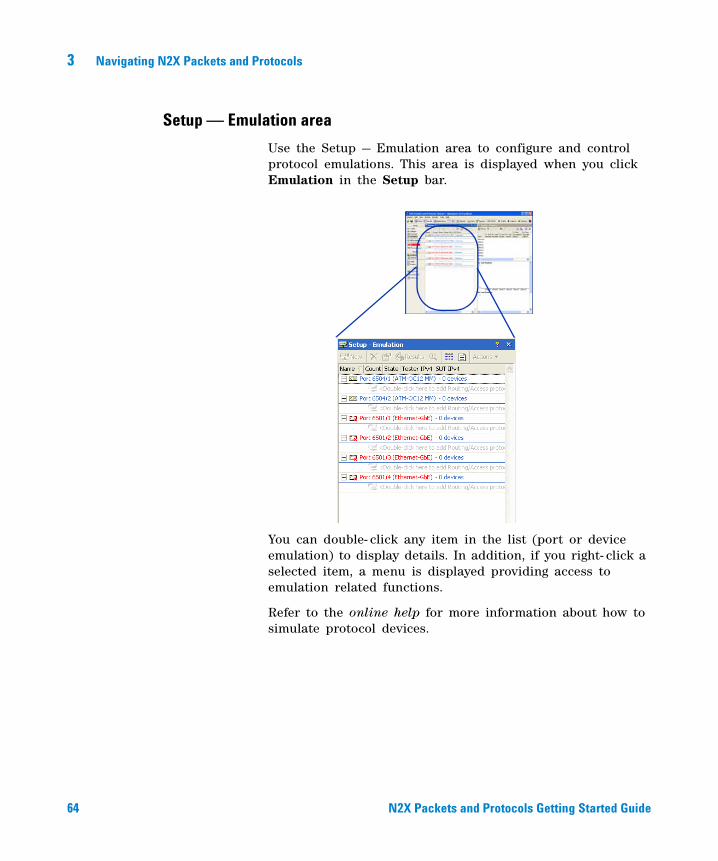
64 N2X Packets and Protocols Getting Started Guide
3 Navigating N2X Packets and Protocols
Setup — Emulation area
Use the Setup — Emulation area to configure and control protocol emulations. This area is displayed when you click Emulation in the Setup bar.
You can double- click any item in the list (port or device emulation) to display details. In addition, if you right- click a selected item, a menu is displayed providing access to emulation related functions.
Refer to the online help for more information about how to simulate protocol devices.
RT900UserGuide.book Page 64 Monday, January 8, 2007 5:47 PM
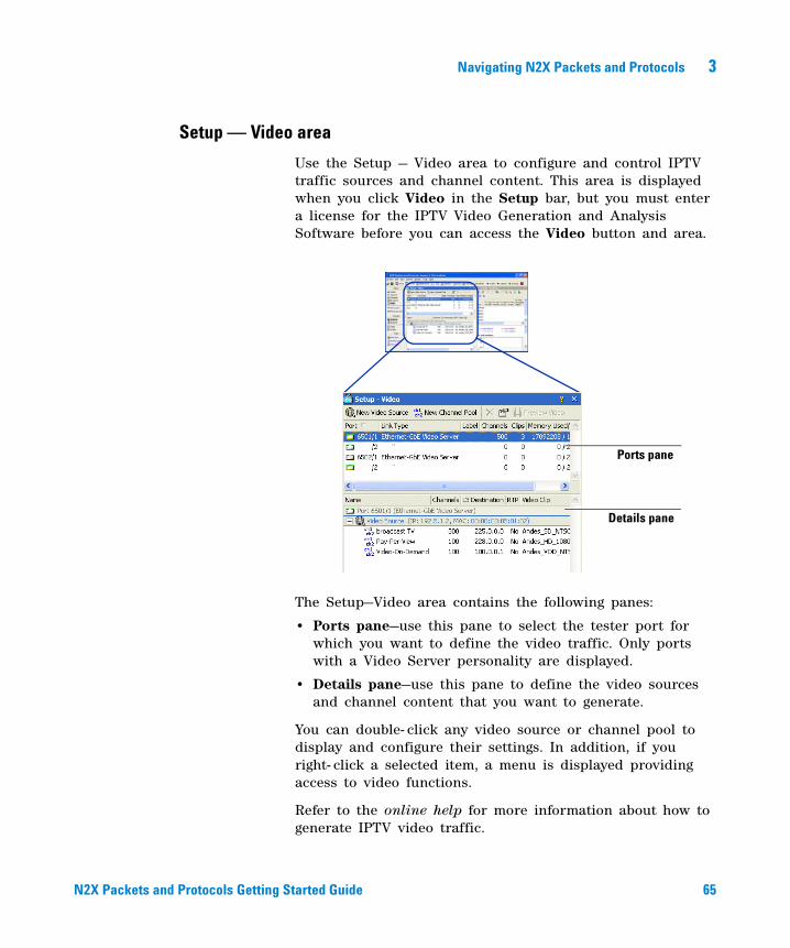
Navigating N2X Packets and Protocols 3
N2X Packets and Protocols Getting Started Guide 65
Setup — Video area
Use the Setup — Video area to configure and control IPTV traffic sources and channel content. This area is displayed when you click Video in the Setup bar, but you must enter a license for the IPTV Video Generation and Analysis Software before you can access the Video button and area.
The Setup—Video area contains the following panes:
• Ports pane—use this pane to select the tester port for which you want to define the video traffic. Only ports with a Video Server personality are displayed.
• Details pane—use this pane to define the video sources and channel content that you want to generate.
You can double- click any video source or channel pool to display and configure their settings. In addition, if you right- click a selected item, a menu is displayed providing access to video functions.
Refer to the online help for more information about how to generate IPTV video traffic.
Ports pane
Details pane
RT900UserGuide.book Page 65 Monday, January 8, 2007 5:47 PM
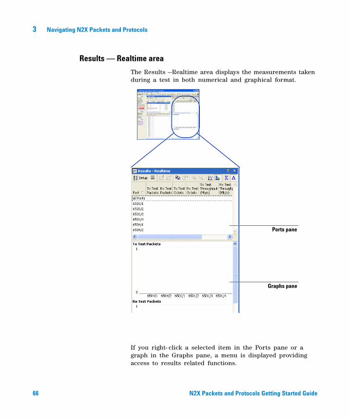
66 N2X Packets and Protocols Getting Started Guide
3 Navigating N2X Packets and Protocols
Results — Realtime area
The Results —Realtime area displays the measurements taken during a test in both numerical and graphical format.
If you right- click a selected item in the Ports pane or a graph in the Graphs pane, a menu is displayed providing access to results related functions.
Ports pane
Graphs pane
RT900UserGuide.book Page 66 Monday, January 8, 2007 5:47 PM

Navigating N2X Packets and Protocols 3
N2X Packets and Protocols Getting Started Guide 67
The Results—Realtime area contains the following panes:
• Ports pane—use this pane to select and display a number of measurements for the traffic you are generating or receiving.
• Graphs pane—use this pane to graphically plot one or more of the measurements selected in the Port Statistics pane. On each graph, you can plot a specific statistic for multiple ports. You can display either bar graphs or line graphs.
The Results—Realtime area has the following icons:
Click ... To ...
select the statistics you want to collect, as well as the port, stream, or field for which you want to collect the statistics.
add or remove measurements for the selected port from the graphs.
copy the selected information. You can select either rows of statistics from the Ports pane, or a graph from the Graphs pane, then paste the information into another application.
specify whether port measurements are collected by stream or by field (for VLANs), and to set the latency threshold.
zoom in or out of a line graph. You cannot use these buttons for a bar graph.
display the results as line graphs (default). Line graphs track the statistic over several sampling intervals, allowing you to chart trends and patterns.
display the results as bar graphs. Bar graphs show the value of the statistic in the last sampling interval.
display the cumulative measurements; the tester displays accumulated values since the start of the test.
RT900UserGuide.book Page 67 Monday, January 8, 2007 5:47 PM
68 N2X Packets and Protocols Getting Started Guide
3 Navigating N2X Packets and Protocols
Refer to the online help for more information about how to view results.
display instantaneous measurements; the tester displays counts for the most recently completed sampling interval.
RT900UserGuide.book Page 68 Monday, January 8, 2007 5:47 PM
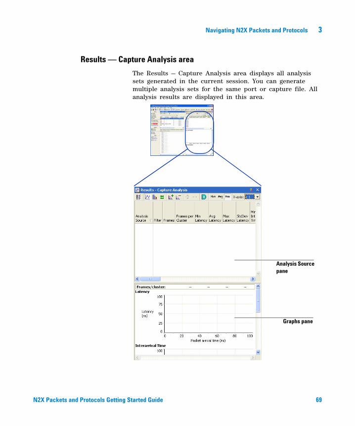
Navigating N2X Packets and Protocols 3
N2X Packets and Protocols Getting Started Guide 69
Results — Capture Analysis area
The Results — Capture Analysis area displays all analysis sets generated in the current session. You can generate multiple analysis sets for the same port or capture file. All analysis results are displayed in this area.
Analysis Source pane
Graphs pane
RT900UserGuide.book Page 69 Monday, January 8, 2007 5:47 PM
70 N2X Packets and Protocols Getting Started Guide
3 Navigating N2X Packets and Protocols
If you right- click a selected item in the Ports pane or a graph in the Graphs pane, a menu is displayed providing access to results related functions.
The Results — Capture Analysis area contains the following panes:
• Analysis Source pane—use this pane to view the measurements that are calculated from all the packets that have passed the analysis filter. The packets are grouped into clusters, which form the base unit from which each measurements is derived.
• Graphs pane—use this pane to view and print the graphical interpretation of the analysis results. You can view:
• time graphs—displays the measurements values over time
• distribution graphs—displays how the range of values per- packet are distributed
The Results area has the following icons:
Click ... To ...
display the Setup Analysis Measurements dialog box. Use this dialog box to:
• select the measurements that you want to graph
• change the default settings for time and distribution graphs
display the graphs as time graphs. Time graphs display the measurement values over time.
display the graphs as distribution graphs. Distribution graphs display how the range of values are distributed.
RT900UserGuide.book Page 70 Monday, January 8, 2007 5:47 PM
Navigating N2X Packets and Protocols 3
N2X Packets and Protocols Getting Started Guide 71
display the Packet Decode dialog box. Use this dialog box to view captured packets as interpreted by their protocol (protocol decode format) in hexadecimal format or in test payload decode format. Note: For this button to display the packet decode details, you must select the analysis set corresponding to the graph for which you want to view details.
add an analysis set to a time or distribution graph. Note: This button is available after you select the analysis set(s) that you want to graph.
remove an analysis set from a time or distribution graph. Note: This button is available after you select the analysis set(s) that you want to remove from the graph.
expand the graph at the selected point.
return to a previous expansion level.
calculate distribution details and display them in the distribution graph format for the selected analysis set(s). This may take several minutes.
display the minimum values of the selected analysis set(s).
Note: This button is available for time graphs only.
display the average values of the selected analysis set(s). Note: This button is available for time graphs.
display the maximum values of the selected analysis set(s). Note: This button is available for time graphs.
select the time graph scale.
RT900UserGuide.book Page 71 Monday, January 8, 2007 5:47 PM

72 N2X Packets and Protocols Getting Started Guide
3 Navigating N2X Packets and Protocols
Refer to the online help for more information about how to view results.
Applications area
The Applications area allows you to run any of the following types of tests:
• Productivity Applications
• Conformance Test Suites
• QuickTest
RT900UserGuide.book Page 72 Monday, January 8, 2007 5:47 PM
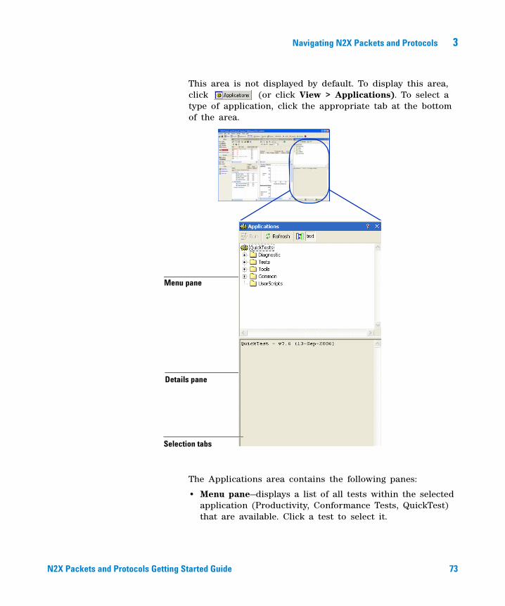
Navigating N2X Packets and Protocols 3
N2X Packets and Protocols Getting Started Guide 73
This area is not displayed by default. To display this area, click (or click View > Applications). To select a type of application, click the appropriate tab at the bottom of the area.
The Applications area contains the following panes:
• Menu pane—displays a list of all tests within the selected application (Productivity, Conformance Tests, QuickTest) that are available. Click a test to select it.
Details pane
Menu pane
Selection tabs
RT900UserGuide.book Page 73 Monday, January 8, 2007 5:47 PM
74 N2X Packets and Protocols Getting Started Guide
3 Navigating N2X Packets and Protocols
• Details pane—displays a description or diagram illustrating the purpose of the selected test. Note: This pane is not available for Conformance Tests.
The Applications area has the following icons:
Click ... To ...
run the selected test.
refresh the list tests.
display a diagram illustrating the selected QuickTest or Productivity test in the Details pane. Note: This is not available on the Conformance tab.
display a text description of the selected QuickTest or Productivity test in the Details pane. Note: This is not available on the Conformance tab.
RT900UserGuide.book Page 74 Monday, January 8, 2007 5:47 PM

75
Agilent N2X Packets and ProtocolsGetting Started Guide
Agilent Technologies
ATo contact us
To contact us 76
RT900UserGuide.book Page 75 Monday, January 8, 2007 5:47 PM
76 N2X Packets and Protocols Getting Started Guide
A To contact us
To contact us
Should you require technical assistance, contact the center in your region.
Americas • USA (Englewood, CO)
Phone: 1-800-829-4444 [email protected]
Asia-Pacific • Email
North-East Asia - [email protected] South Asia-Pacific - [email protected]
• Australia Phone: 1-800-629-485
• China Phone: 800-810-0189
• Hong Kong Phone: 800-930-871
• India Phone: 1-600-112-929
• Korea Phone: (82-2) 2004-5004 Toll Free: 080-769-0800
• Malaysia Phone: 1-800-888-848
• New Zealand Phone: 0800-738-378
• Philippines Phone: (63-2) 842-6802 Toll Free: 1-800-1651-0170
• Singapore Phone: 1-800-375-8100
• Taiwan Phone: 0800-047-866
• Thailand Phone: (66-2) 268-1345 Toll Free: 1-800-226-008
Japan• Tokyo
Phone: 0120-421-345 [email protected]
Europe• Benelux
Netherlands: 31 020 547 2111 Belgium: 32 02 404 93 40 [email protected]
• DACH Germany: 0180 524 6333 Austria: 43 01 251257006 Switzerland: 41 01 7359300/9200 [email protected]
• Denmark Phone: 45-70 13 15 15 [email protected]
• Finland Phone: 358-010-855 21 00 [email protected]
• France International: 33 01 64 53 56 23 France: 08 25 01 07 00 [email protected]
• Italy Phone: 39-02-92 60 84 84 [email protected]
• Norway Phone: 47-23 25 37 00 [email protected]
• Spain Phone: 34-91 631 33 00 [email protected]
• Sweden Phone: 46-08-50 64 86 86 [email protected]
• UK & Ireland UK: 44 07004 666 666 Ireland: 1 890 92 42 06 [email protected]
RT900UserGuide.book Page 76 Monday, January 8, 2007 5:47 PM
To contact us A
N2X Packets and Protocols Getting Started Guide 77
For faster service...
We require the following information to troubleshoot problems. The more information you provide, the faster we will be able to assist you.• your name and contact details (phone or email)• your Controller PC’s model and serial number• your N2X Packets and Protocols test cards’ model • approximate purchase date• software version (see the application’s splash screen or
Help menu)• software installed (including patches)• specific details of the problem
• CollectDiagnostics details
• modules being used in the test
• router configuration
For support through the World Wide Web...
You can also get technical support through the World Wide Web:
• http://www.agilent.com/comms/N2X
This site provides general information about the tester: news, product information, data sheets, and brochures.
• Technical Support site
Click “Technical Support” on the main web page. This site provides support for registered customers: the latest software, service packs, user guides, online help, and application notes. See Registration below to register for this. To access this site, you need the User Name and Password that was emailed to you when you registered for this support. If you lose or forget this password, use the "Get Password Assistance" link from the Login page.
• Registration site
Click “Register for a Free Password” on the main Technical Support page. Use this site to register for access to the above support site. To register, you need a license
RT900UserGuide.book Page 77 Monday, January 8, 2007 5:47 PM

78 N2X Packets and Protocols Getting Started Guide
A To contact us
key or SES Agreement number (shipped with your order). A User Name and Password will be emailed to you within minutes.
RT900UserGuide.book Page 78 Monday, January 8, 2007 5:47 PM
N2X Packets and Protocols Getting Started Guide 79
A
about N2X Packets and Protocols, 16addresses
IPv4, 24IPv6, 24
Agilent Technologies, contacting us, 76
Analysis Source pane, 70analyzing data, 37, 38API, 40application
N2X Packets and Protocols, 50software, 42
Application Programming Interface (API), 40
Applicationsarea, 72Details pane, 74Menu pane, 73
areaApplications, 72Results, 66Results - Capture Analysis, 69Results - Realtime, 66Setup - Emulation, 64Setup - Topology, 62Setup - Traffic, 58Setup - Video, 65
ATMconfiguring, 24
B
BGP-4 MPLS VPNs, 21
C
Capturemenu, 51
capture analysis results, 69capturing data, 37, 38cards, 43CE mark, 3configuring
data capture, 38
Ethernet, 24link layer, 24physical layer, 24POS, 24tester, 23
Conformance tests, 41contacting Agilent Technologies, 76creating traffic mesh, 32creating traffic stream groups, 32CSA mark, 3Customer Support, contact
numbers, 76
D
data analysis, 37, 38data capture, 37, 38
configuring, 38decodes, viewing, 39defining
measurements, 32, 34PDU, 32traffic, 30traffic flow, 32traffic profiles, 32
Details pane, 59, 65
E
Edit menu, 51email, Agilent Technologies, 76emulating protocols, 20, 26Emulation
area, 64menu, 51
Ethernetconfigure, 24interfaces supported, 43
exiting, 47
F
fast reroute, 20forwarding performance testing, 20Frame Relay
configuring, 24
functional conformance tests, 41
G
generating traffic, 30, 34graceful restart, 20Graphical User Interface (GUI), 40, 50Graphs pane, 67, 70graphs, viewing, 36
H
H.264 traffic, 19hardware test cards, 43Help
buttons, 48menu, 48, 51
high availability, 20
I
icon bar, 52interfaces, 40IPTV. See VideoIPv4
addresses, 24IPv6
addresses, 24ISM 1-A mark, 3
J
Journal of Internet Test Methodologies, 45
L
L2oMPLS, 21launching
N2X Packets and Protocols, 46online help, 48
Layer 2 MPLS VPN, 21, 27Layer 3 BGP-4 MPLS VPNs, 21
RT900UserGuide.book Page 79 Monday, January 8, 2007 5:47 PM
80 N2X Packets and Protocols Getting Started Guide
link layer, configure, 24logging out, 47
M
make-before-break, 20MDI, 19measure QoS, 18measurements
selecting, 32, 34viewing, 36
Menu bar, 51Menu pane, Applications, 73MPEG traffic, 19
N
N2X Packets and Protocolsabout, 16application, 50capabilities, 16exiting, 47window, 50
navigating N2X Packets and Protocols, 49
network stress testing, 19non-stop forwarding, 20
O
online helpbuttons, 48displaying, 48menu, 48
optical laserswarning, 3
P
packet decodes, viewing, 39pane
Analysis Source, 70Applications Details, 74Applications Menu, 73
Details, 59, 65, 74Graphs, 67, 70Port Statistics, 67Ports, 58, 65
PDUdefining, 32
performance testing, 17phone support, 76physical layer, configure, 24Ports pane, 58, 65, 67ports, selecting, 24POS
configure, 24interfaces supported, 43
product support, 76Productivity Applications, 41protocol
emulation, 20, 26stress testing, 27testing, 25
protocol conformance test, 41
Q
QoS testing, 18QuickTests, 41
R
realtime results, 66Results
bar, 56results
capture analysis, 69realtime, 66
Results - Capture Analysis area, 69Results - Realtime area, 66Results menu, 51results, viewing, 34run tests, 22
S
safety symbols, 3selecting
measurements, 32, 34
ports, 24sending
traffic, 32, 34Session menu, 51Setup - Emulation area, 64Setup - Topology area, 62Setup - Traffic area, 58Setup - Video area, 65Setup bar, 54simulating topologies, 21software applications, 42starting
N2X Packets and Protocols, 46traffic, 32, 34
statisticsselect, 34viewing, 34, 36
stream group, create, 32stress testing, 19stress testing protocols, 27support, 76symbols, safety, 3
T
Tclintroduction, 40
technical support, 76test cards, 43test, run, 22testing
forwarding performance, 20network stress thresholds, 19protocol emulation, 20, 26protocols, 25QoS, 18stress protocols, 27topologies, 21traffic performance, 17
thresholds, stress testing, 19toolbar, 52Tools bar, 57Tools menu, 51Topology
area, 62menu, 51
topology testing, 21Traffic
RT900UserGuide.book Page 80 Monday, January 8, 2007 5:47 PM
N2X Packets and Protocols Getting Started Guide 81
area, 58menu, 51
trafficcapture, 37capturing, 38create stream group, 32create traffic mesh, 32defining, 30defining profiles, 32sending, 34start, 32
traffic flow, defining, 32traffic mesh, create, 32traffic performance testing, 17triple play, 19
V
Videoarea, 65menu, 51testing, 19
View menu, 51viewing
graphs, 36packet decode data, 39statistics, 34statistics table, 36
VPLS, 21VPN, 29
W
warnings, 3WEEE directive, 4
X
Xenpakinterfaces supported, 43
XP, XR, XS cards, 43
RT900UserGuide.book Page 81 Monday, January 8, 2007 5:47 PM

![NAVAL POSTGRADUATE SCHOOLThe candidate boards were: BAE RAD750 [13], Motorola MCP750 [25], Raspberry Pi [16], and Aeroflex-Gaisler GR-LEON4-ITX [14] and GR-CPCI-LEON4-N2X [15]. …](https://img.dokumen.tips/doc/110x75/6142ad15b7accd31ec0eda52/naval-postgraduate-school-the-candidate-boards-were-bae-rad750-13-motorola-mcp750.jpg)