Embed Size (px)
Citation preview

Hardware (P)ReviewHardware (P)Review
1© 2008 Universität Karlsruhe (TH), System Architecture Group
Gerd Liefländer
WT 2008/09System Architecture Group
Literature Bacon, J.: Operating Systems (3) Davis, W.: Operating Systems (2) Hennessy, J.: Computer Architecture, 2003 Nehmer, J.: Grundlagen moderner Betriebssysteme (2) Messmer, H.P.: PC Hardwarebuch: Aufbau,
Funktionsweise, Programmierung,
Introduction
© 2008 Universität Karlsruhe (TH), System Architecture Group 2
Funktionsweise, Programmierung, Addison Wesley, 7. Auflage, 2004
Stallings, W.: Computer Organization and Architecture, 2003 Patterson, D.: Computer Organization and Design:
The Hardware/Software Interface Schröder-Preikschat, W.: SOS I, Ch. III Organisation von
Rechensystemen, Uni Erlangen Silberschatz, A.: Operating System Concepts (2) Tanenbaum, A.: Modern Operating Systems (1)
Recommended Links
http://www.desy.de/user/projects/C++/courses/cc/Tutorial/
http://wwwh.eng.cam.ac.uk/help/tpl/languages/java/cuedjavanotes/CUEDC++.html
http://www.cee.hw.ac.uk/~rjp/Coursewww/
© 2008 Universität Karlsruhe (TH), System Architecture Group 3
http://newtech.maconstate.edu/academics/ITEC4266Assignments.asp
http://salsa.cit.cornell.edu/cs213-sp01/lectures.html
Slides from Theo Ungerer (Uni Augsburg): Systemnahe Informatik und Kommunikationssysteme
Agenda Introduction, Motivation HW Overview and Classification Computer Organization
Hardware/Software Hierarchy Semantic Gap
Introduction
© 2008 Universität Karlsruhe (TH), System Architecture Group 4
Note: See related HW courses on the web
p
Computer Components Processor (CPU) Memory Hierarchy Caching and Locality Exception/Interrupt Physical-I/O
MotivationMotivation
5© 2008 Universität Karlsruhe (TH), System Architecture Group
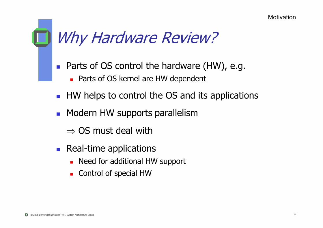
Why Hardware Review?
Parts of OS control the hardware (HW), e.g. Parts of OS kernel are HW dependent
HW helps to control the OS and its applications
Modern HW supports parallelism
Motivation
© 2008 Universität Karlsruhe (TH), System Architecture Group 6
Modern HW supports parallelism
OS must deal with
Real-time applications Need for additional HW support
Control of special HW

HW Abstraction versus HW Ignorance
Designing and implementing an OS without knowing your HW
inefficient systeminsecure system
Motivation
© 2008 Universität Karlsruhe (TH), System Architecture Group 7
insecure system
Designing an OS without abstraction
inflexible system non portable system

Overview and ClassificationOverview and Classification
8© 2008 Universität Karlsruhe (TH), System Architecture Group
ClassificationArchitecturesTrends
Hardware Overview
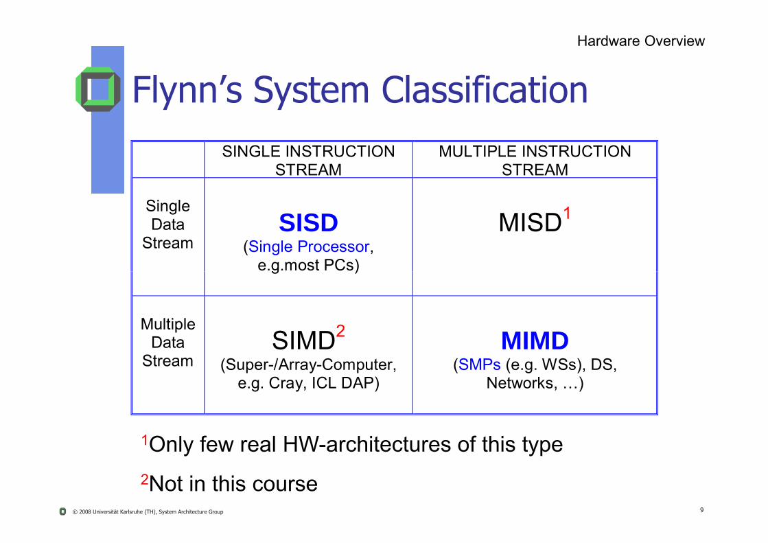
SINGLE INSTRUCTION STREAM
MULTIPLE INSTRUCTION STREAM
Single Data
Stream
SISD
(Single Processor, e.g.most PCs)
MISD1
Flynn’s System Classification
© 2008 Universität Karlsruhe (TH), System Architecture Group 9
g )
Multiple
Data Stream
SIMD2
(Super-/Array-Computer, e.g. Cray, ICL DAP)
MIMD
(SMPs (e.g. WSs), DS, Networks, …)
1Only few real HW-architectures of this type2Not in this course

Uniprocessor*
1 CPU + specialFront-/Backend-
Processors
Dataflow-/Functional Language
MachinesLAN
HW Base for Concurrent Systems*More concurrency inside
CPU (multi threading)
Hardware Overview
Increasing concurrency
© 2008 Universität Karlsruhe (TH), System Architecture Group 10
Processors
Vector-/Array-Processors MAN
WANMulticomputer-Multiprocessors
Loosely coupled
Homo-/Hetero-geneous SMPs
Tightly coupled

Classification of Parallel Computers Homogeneity of
HW/ OS/ application
Synchrony Bulk synchronized, loosely synchronized
Interaction mechanisms
Hardware Overview
© 2008 Universität Karlsruhe (TH), System Architecture Group 11
Interaction mechanisms Shared variables, message passing
Address space Shard memory, distributed memory, uniform-, non uniform
access
Memory model EREW, CREW, CRCW / consistency
EREW = exclusive read and exclusive writeCREW = concurrent read and exclusive write

Classification of Parallel Computers
Pragmatic: Shared memory multiprocessors
Hyper Threaded
SMP
NUMA CC NUMA
Hardware Overview
~ 2 – 8 threads
~ 2 – 64 CPUs
© 2008 Universität Karlsruhe (TH), System Architecture Group 12
no
NUMA, CC-NUMA
MPP (Massively parallel) NUMA, CC-NUMA
Message passing MP, NORMA
Cluster
NORMA = No Remote Memory Access, i.e. interaction with other processors via messages
~ 8 K CPUs

Computer ArchitectureComputer Architecture
13© 2008 Universität Karlsruhe (TH), System Architecture Group
Computer Architectures
Single Processor System
Multi Processor System (SMP)
Hardware Overview
© 2008 Universität Karlsruhe (TH), System Architecture Group 14
Distributed Systems (LANs …)
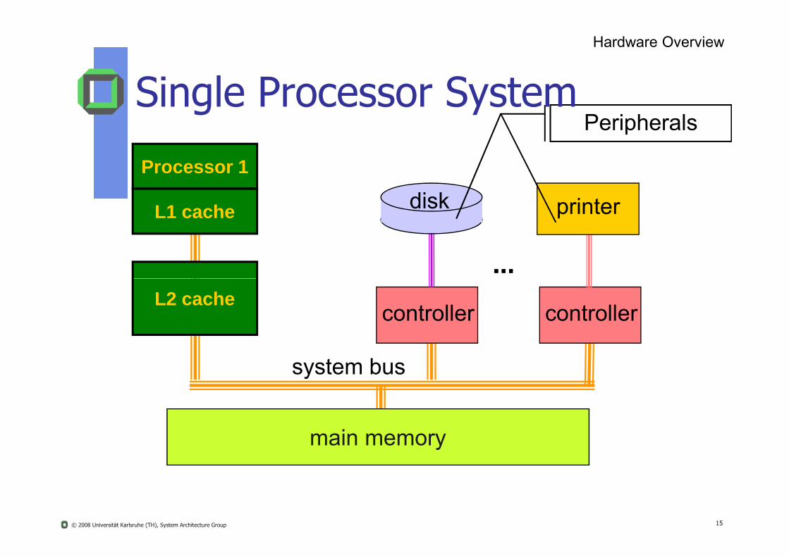
Processor 1
......
L1 cache disk printer
PeripheralsSingle Processor System
Hardware Overview
© 2008 Universität Karlsruhe (TH), System Architecture Group 15
system bus
controller controller
main memory
L2 cache
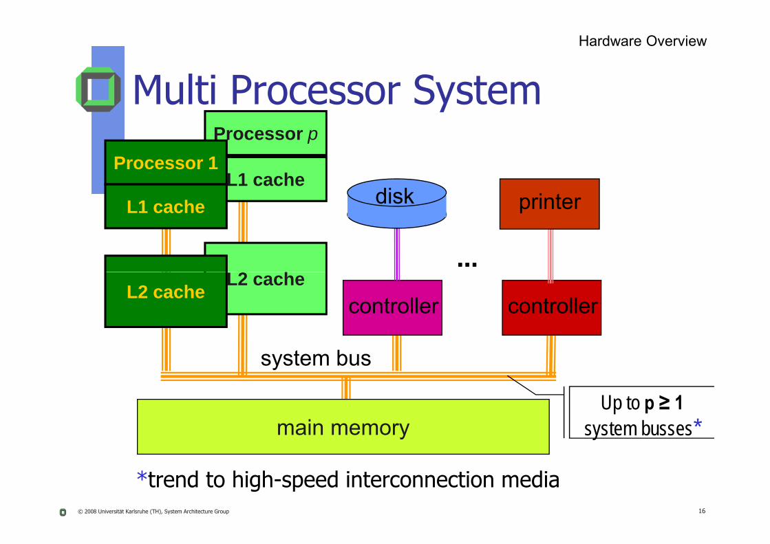
Processor p
L1 cache
2
Processor 1
......
L1 cache disk printer
Hardware Overview
Multi Processor System
© 2008 Universität Karlsruhe (TH), System Architecture Group 16
L2 cache
system bus
controller controller
main memory
L2 cache
Up to p ≥ 1system busses*
*trend to high-speed interconnection media
Hardware Overview
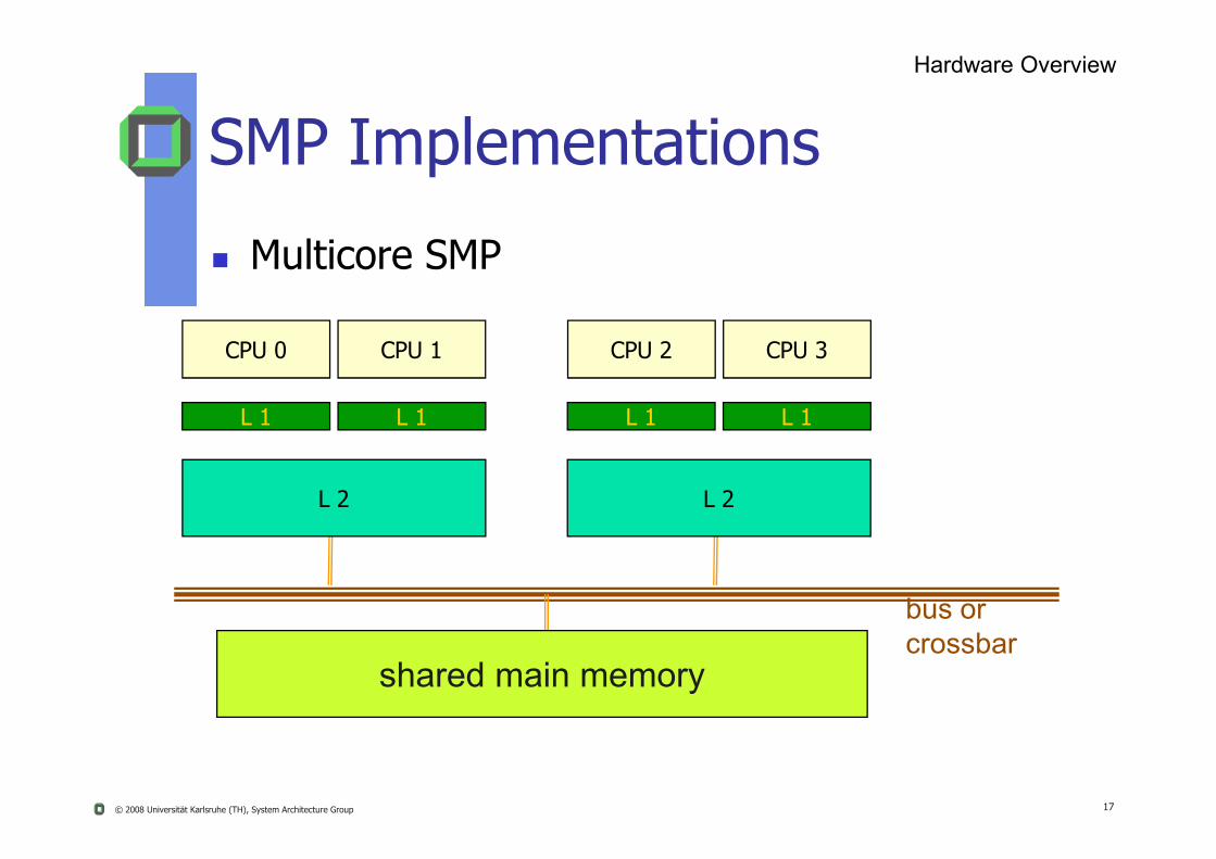
SMP Implementations
Multicore SMP
L 1 L 1 L 1 L 1
CPU 0 CPU 1 CPU 2 CPU 3
© 2008 Universität Karlsruhe (TH), System Architecture Group 17
bus orcrossbar
shared main memory
L 2 L 2

Hardware Overview
SMP Implementations
L 1CPU 0
Hyperthreaded SMP
L 1CPU 1
Thread 0 Thread 1 Thread 2 Thread 3
© 2008 Universität Karlsruhe (TH), System Architecture Group 18
bus orcrossbar
shared main memory
L 2 L 2
L 1 L 1CPU local caches

Caches
Cache Architecture Cache Coherence
Write Through Write Back Snooping Protocols
MESI
© 2008 Universität Karlsruhe (TH), System Architecture Group 19
MOESI …
Memory Pinning
Don’t miss it!!! Why?
It’s very interesting You’ll need it in the examination Liedtke et al: OS controlled cache predictability for real-time systems Liedtke: Caches versus object allocation …

mm
L 2
P/L1net-card
lpr
mm
L 2
P/L1net-card
lpr
Print Server
DisklessClient
LAN (different topologies see
Hardware Overview
Preview: Local Area Networks
© 2008 Universität Karlsruhe (TH), System Architecture Group 20
mm
L 2
P/L1disk net-
card
Client
mm
L 2
P/L1disknet-
card L 2
P/L1disk
FileServer
disk
(different topologies see course distributed systems)

Computer Architecture
Instruction Set
Compiler
Operating
System(Windows XX)
Application (Netscape)
Software Assembler
Hardware Overview
© 2008 Universität Karlsruhe (TH), System Architecture Group 21
Instruction SetArchitecture
I/O systemProcessor
Digital Design
Circuit Design
Datapath & Control
Transistors
MemoryHardware

Levels of Representation
Assembly Language Program (e.g. MIPS)
Compiler
High Level Language Program (e.g., C)
temp = v[k];v[k] = v[k+1];v[k+1] = temp;
lw$t0,0($2)lw$t1,4($2)$ $
Hardware Overview
© 2008 Universität Karlsruhe (TH), System Architecture Group 22
g ( g )
Control Signal Specification
Machine Interpretation
sw$t1,0($2)sw$t0,4($2)
Machine Language Program (MIPS)
Assembler
0000 1001 1100 0110 1010 1111 0101 10001010 1111 0101 1000 0000 1001 1100 0110 1100 0110 1010 1111 0101 1000 0000 1001 0101 1000 0000 1001 1100 0110 1010 1111
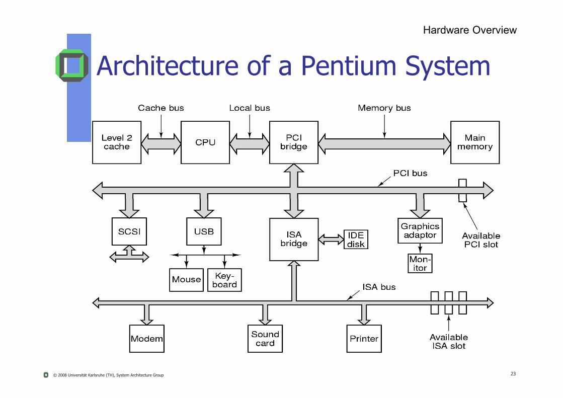
Architecture of a Pentium System
Hardware Overview
© 2008 Universität Karlsruhe (TH), System Architecture Group 23
Trend in CPU Design?
Hardware Overview
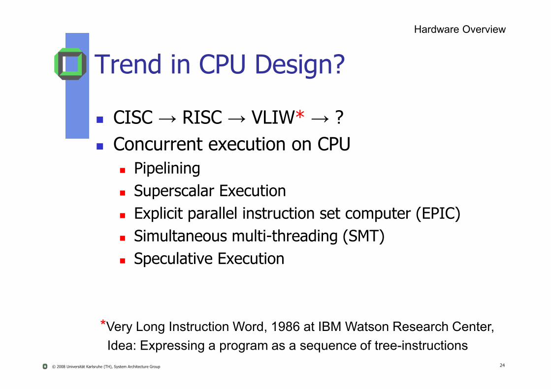
CISC → RISC → VLIW* → ? Concurrent execution on CPU
Pipelining Superscalar Execution
© 2008 Universität Karlsruhe (TH), System Architecture Group 24
*Very Long Instruction Word, 1986 at IBM Watson Research Center,Idea: Expressing a program as a sequence of tree-instructions
Superscalar Execution Explicit parallel instruction set computer (EPIC) Simultaneous multi-threading (SMT) Speculative Execution

What do Computers do?Hardware Overview
© 2008 Universität Karlsruhe (TH), System Architecture Group 25
Computers manipulate representations of things,i.e. they interpret information!
What can you represent with N bits? 2N things Numbers! Characters! Pixels! Dollars! Positions! Instructions! Depends on what operations you do with them

HW ComponentsHW Components
26© 2008 Universität Karlsruhe (TH), System Architecture Group
CPUMemoryInterconnectionI/O ControllerI/O Devices

Components of a Computer
Processor(active)
Computer
Memory(passive)
Devices
Keyboard, Mouse
Disk
Computer Components
© 2008 Universität Karlsruhe (TH), System Architecture Group 27
Control(“brain”)
Datapath(“brawn”)
(where programs, data live whenrunning)
Input
Output
Display, Printer
(where programs (data) live when not running)

Monitor
Example: PC-Architecture
Computer Components
© 2008 Universität Karlsruhe (TH), System Architecture Group 28
Bus

Basic Components
Processors (CPUs)
Memory hierarchy: (e.g. disk, RAM, caches)
Interconnection (e.g. buses, cross bars) Control and/or data lines
Hardware Overview
© 2008 Universität Karlsruhe (TH), System Architecture Group 29
I/O: controllers, channels, I/O-processors hardware controlling devices and transporting data between
devices, consisting of an extra CPU + memory, e.g. IDE controller, keyboard controller, network card, DMA, Timer / real-time clock, UART (RS232C, V.24, modem…)
Peripheral Devices disk, printer, keyboard, mouse, monitor, speaker,
microphone, ...
ProcessorProcessor
30© 2008 Universität Karlsruhe (TH), System Architecture Group
RegistersInstructionsModes
Processor Overview
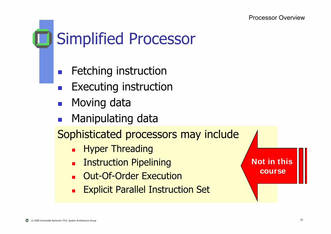
Simplified Processor
Fetching instruction Executing instruction Moving data
Manipulating data
© 2008 Universität Karlsruhe (TH), System Architecture Group 31
Manipulating dataSophisticated processors may include
Hyper Threading Instruction Pipelining Out-Of-Order Execution Explicit Parallel Instruction Set
Not in this course
Simplified API of a CPU
Instruction Set
General and Special Registers
≥2 E ti P M d
Processor Overview
© 2008 Universität Karlsruhe (TH), System Architecture Group 32
n ≥2 Execution or Processor Modes

Instruction Set
Privileged Instructions If executed in user mode
HW raises an exception
Non Privileged Instructions
Processor Overview
© 2008 Universität Karlsruhe (TH), System Architecture Group 33
Non-Privileged Instructions Executable in user- as well as in kernel-mode
Give some examples
Why do we need privileged instructions?
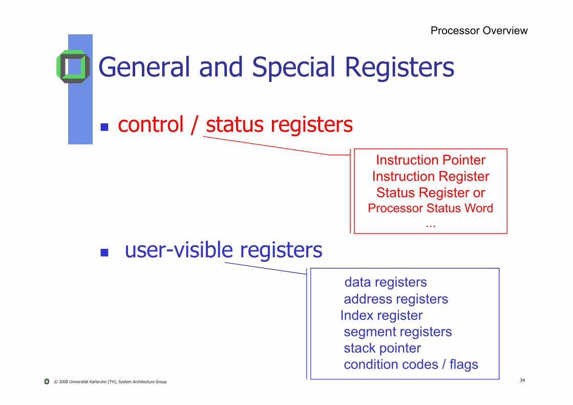
Instruction PointerInstruction RegisterStatus Register or
General and Special Registers
control / status registers
Processor Overview
© 2008 Universität Karlsruhe (TH), System Architecture Group 34
Processor Status Word...
user-visible registersdata registersaddress registersIndex registersegment registersstack pointercondition codes / flags

OS Basics
OS kernel = bunch of code sitting around in RAM, waiting to be executed Triggered by system calls, exceptions, or interrupts
“Kernel” gets control when system is booting Depends a lot on the underlying hardware
Roughly most PC have a BIOS (basic in/output system) that can
Processor Overview
© 2008 Universität Karlsruhe (TH), System Architecture Group 35
Roughly, most PC have a BIOS (basic in/output system) that can access primitive hardware devices Disk, keyboard, display
When powered on, BIOS has a small program that knows how to load a program from some I/O device(s), e.g. first try Floppy, then CD ROM, then disk
The program loaded by the BIOS is the kernel Sometimes it’s actually a somehow simpler, prototype kernel This prototype kernel knows how to load the ultimate kernel

Booting or Computer Startup
Bootstrap program is loaded at power-up or reboot
Typically stored in ROM or EEPROM, generally known as firmware
Processor Overview
© 2008 Universität Karlsruhe (TH), System Architecture Group 36
known as firmware
Initializes all aspects of the system
Loads OS-kernel and starts its execution

Two1 Execution Modes
Kernel Mode
User Mode
Why?
Processor Overview
© 2008 Universität Karlsruhe (TH), System Architecture Group 37
Why?
What mode switches are typical?
1 architectures with more than 2 execution modes

User versus Kernel Mode
What makes a kernel different from user programs? Only kernel programs can execute privileged instructions
Examples of privileged instructions: Access I/O devices
Poll for I/O perform DMA catch hardware interrupt
Processor Overview
© 2008 Universität Karlsruhe (TH), System Architecture Group 38
Poll for I/O, perform DMA, catch hardware interrupt Manipulate the MMU and memory state
Set up page tables, load/flush TLB Configure various mode bits
Interrupt priority level, software trap vectors Call HALT instruction
Put CPU into low-power or idle state until next interrupt
Enforced by CPU CPU checks current protection level on each instruction

Boundary Crossing1
User-to-kernel: How does the kernel get control? At boot time: kernel loaded as the first OS program System call: explicit call by an application into the OS Exception, e.g. “division by Zero” Hardware interrupt
Processor Overview
© 2008 Universität Karlsruhe (TH), System Architecture Group 39
Software interrupt
Kernel-to-user: How does an application gets control? OS sets up registers, protection domains, and MMU for the
application to run the very first time OS returns from a kernel activity and jumps to the next
instruction of an application
1crossing user-kernel-boundary costs some/many cycles

Protection Rings
multiple levels of protection domains, e.g.
x86 has 4 protection rings
Code in a less privileged ring can not directly call code in a more privileged ring
Processor Overview
© 2008 Universität Karlsruhe (TH), System Architecture Group 40
code in a more privileged ring
Ring 0 = OS kernel (~ kernel mode)
Ring 3 = application code (~ user mode)
Rings 1+2 can be used for less-privileged OS code
Third party device drivers

Basic Instruction Cycle
Processor Overview
© 2008 Universität Karlsruhe (TH), System Architecture Group 41
CPU fetches the next instruction (with operands) from memory.CPU executes the instructionInstruction Pointer (IP) holds address of the instruction to be fetched next, automatically incremented after each fetch

Execution Steps
memory
1. Instruction fetch
Processor Overview
© 2008 Universität Karlsruhe (TH), System Architecture Group 42
CPU controllogic
registers2. Instruction decode
3. Control signals5. Execution
4. Data fetch
6. Result store
ALU

Simple Model of Computation
Fetch-execute cycle Load memory contents from
address in instruction pointer (IP)
Store contents in instruction (IR)IP: 0x0100
Processor Overview
© 2008 Universität Karlsruhe (TH), System Architecture Group 43
Store contents in instruction (IR)
Execute IR (update SR)
Increment IP
Repeat
IR: 0xa3f2
SP: 0xcbf4
Status Register
Register R1
…
Register RrNot visible on all CPU architectures

Simple Model of Computation
Stack Pointer Status Register
Condition Code Positive result Negative result IP: 0x0100
Processor Overview
© 2008 Universität Karlsruhe (TH), System Architecture Group 44
Zero Mode bit(s)
General Purpose Register Operands of most instructions Enables to minimize
memory references
IR: 0xa3f2
SP: 0xcbf4
Status Register
Register R1
…
Register RrNot visible on all CPU architectures

Privileged Mode Operation
To protect OS executionm ≥ 2 modes are available Kernel (system) mode
All instructions are executableIP: 0x0100
MMU Registers
…
Exception type
Interrupt Mask
Processor Overview
© 2008 Universität Karlsruhe (TH), System Architecture Group 45
All registers are accessible
User mode Only “safe” subset of instructions
are executable, e.g. not allowed:
disable interrupts Only “safe” registers are accessible
IR: 0xa3f2
SP: 0xcbf4
Status Register
Register R1
…
Register Rr

Safe Instructions and Registers
Instructions and registers are safe if
Only affect application itself
Cannot be used to interfere with OS
Processor Overview
© 2008 Universität Karlsruhe (TH), System Architecture Group 46
OS Other applications
Cannot be used to violate OS policy
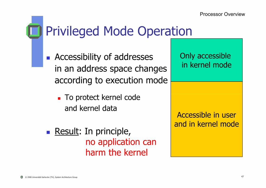
Privileged Mode Operation
Accessibility of addressesin an address space changesaccording to execution mode
Only accessible in kernel mode
Processor Overview
© 2008 Universität Karlsruhe (TH), System Architecture Group 47
To protect kernel code and kernel data
Result: In principle, no application canharm the kernel
Accessible in userand in kernel mode

Atomicity
What does it mean? atomic instructions, used to implement locks, e.g.
Test-And-Set (TAS), if word contains a given value, set to new value
Compare_And-Swap (CAS), if word equals value, swap old
Processor Overview
© 2008 Universität Karlsruhe (TH), System Architecture Group 48
p _ p ( ), q , pvalue with new value
…
atomic operations …
atomic program sections see critical section
Hint: Read http://www-128.ibm.com/developerworks/library/pa-atom/

MemoryMemory
49© 2008 Universität Karlsruhe (TH), System Architecture Group
Memory HierarchyCachingLocalityProtection
Why Memory Hierarchy?
huge performance gap between modern CPUs and main memory (RAM)
a principle to overcome this gap
© 2008 Universität Karlsruhe (TH), System Architecture Group 50
Locality
Temporal locality
Spatial locality

RegisterL1 CacheL2 Cache
cheaper,slower,bigger,
less frequently accessed
per processor
shared or
Memory Hierarchy
Memory Overview
© 2008 Universität Karlsruhe (TH), System Architecture Group 51
Main Memory
Disk Memory
Archive Memory (e.g. Tape)
L3 Cacheshared or
per processor
Note: Parts of main memory may be used as a disk cache
Memory Overview
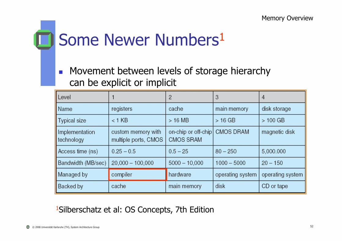
Some Newer Numbers1
Movement between levels of storage hierarchy can be explicit or implicit
© 2008 Universität Karlsruhe (TH), System Architecture Group 52
1Silberschatz et al: OS Concepts, 7th Edition
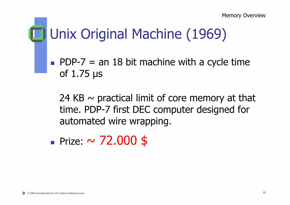
Unix Original Machine (1969)
Memory Overview
PDP-7 = an 18 bit machine with a cycle time of 1.75 µs
24 KB ~ practical limit of core memory at that
© 2008 Universität Karlsruhe (TH), System Architecture Group 53
p ytime. PDP-7 first DEC computer designed for automated wire wrapping.
Prize: ~ 72.000 $

Ritchie & Thompson + PDP 11
Unix needed 16 KB*
U ld l t 8 KB
Example
© 2008 Universität Karlsruhe (TH), System Architecture Group 54
Users could only get 8 KBfor their applications
*at that time a really tiny OS

Registers*
Registers General purpose Floating point Multimedia Special (instruction pointer, status)
Typical for RISC architectures:
Memory Overview
© 2008 Universität Karlsruhe (TH), System Architecture Group 55
Typical for RISC architectures: 32 general purpose (32 bit or 64 bit) 32 floating point (64 bit IEEE) Multimedia (64, 128, or 256 bit)
Intel IA 32 Pentium
8 general purpose, 8 floating point (or 8 multi media) IA 64 Itanium
128 general purpose, 128 floating point
*Register windows

Observation
Principle of Location
To support the execution of programs, faster -but limited caches- are useful to keep up with modern CPUs
© 2008 Universität Karlsruhe (TH), System Architecture Group 56
“Natura non saltat” ~ evolution takes time~ program execution has some localityi.e. what’s in the caches will be reused

Principle of Locality
Observation:
10 % of code does 90% of work*
Principle of Location
© 2008 Universität Karlsruhe (TH), System Architecture Group 57
*Principle a “law of nature” ?
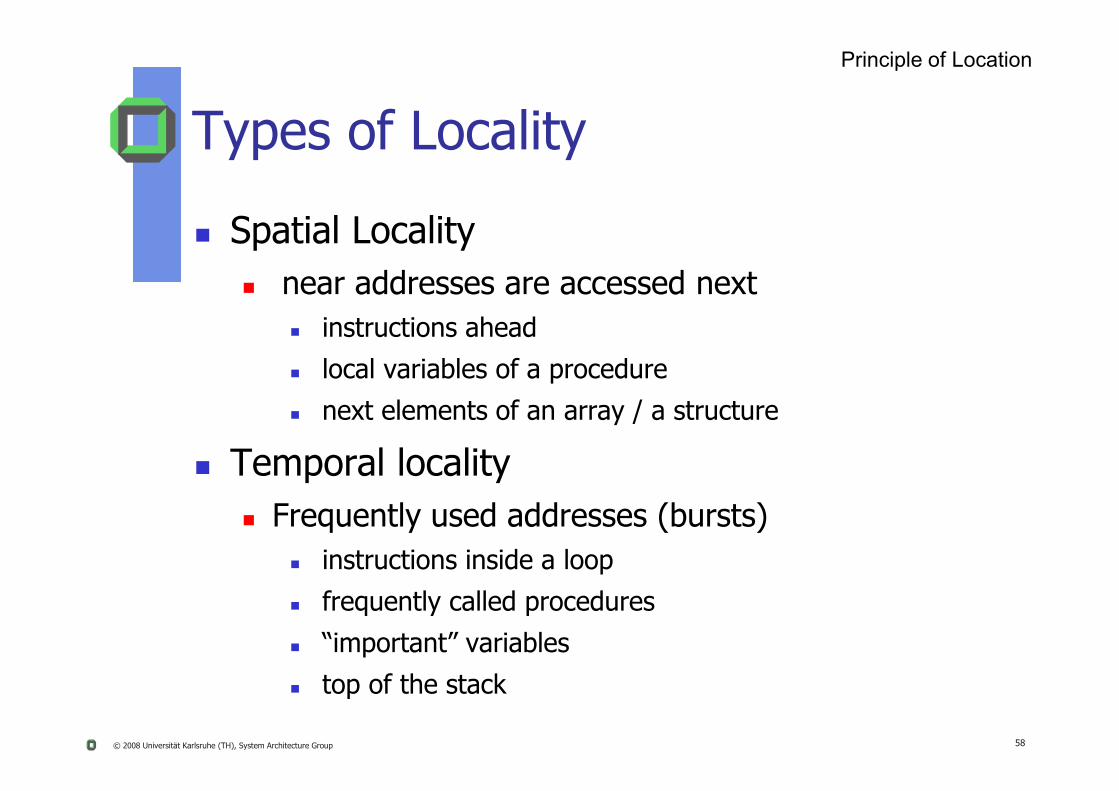
Types of Locality
Spatial Locality near addresses are accessed next
instructions ahead
local variables of a procedure
Principle of Location
© 2008 Universität Karlsruhe (TH), System Architecture Group 58
next elements of an array / a structure
Temporal locality Frequently used addresses (bursts)
instructions inside a loop
frequently called procedures
“important” variables
top of the stack
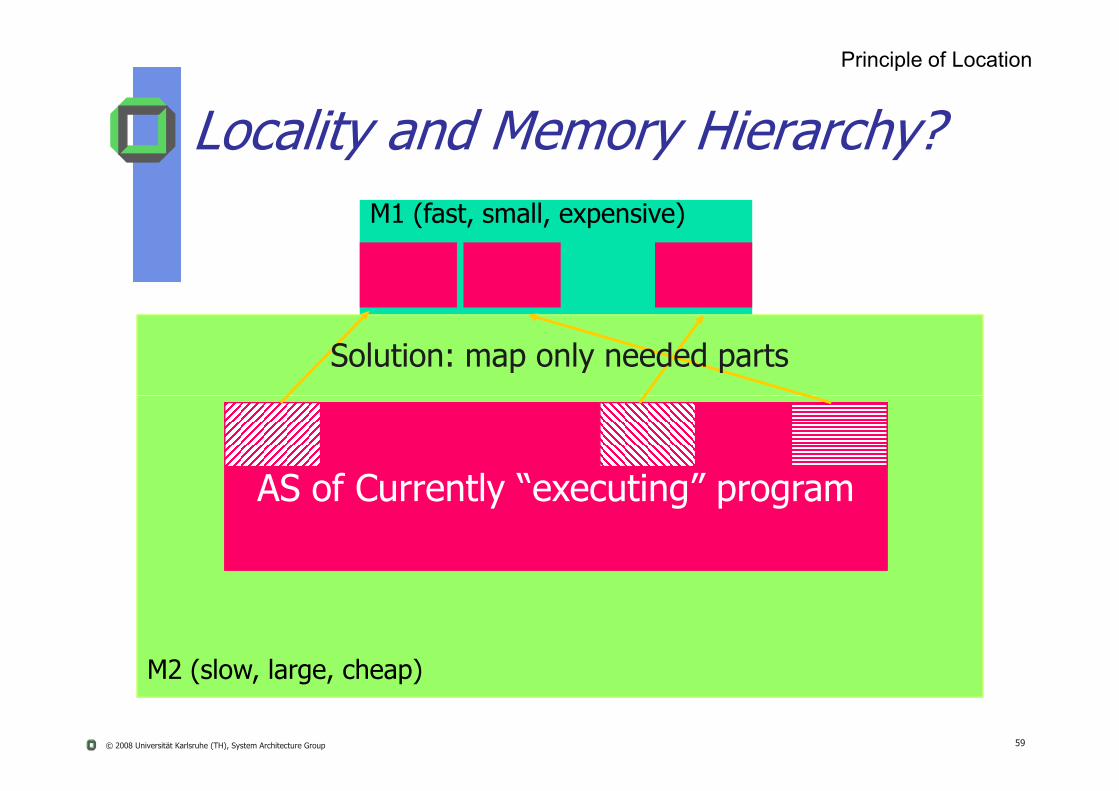
M1 (fast, small, expensive)
Solution: map only needed parts
Principle of Location
Locality and Memory Hierarchy?
© 2008 Universität Karlsruhe (TH), System Architecture Group 59
AS of Currently “executing” program
M2 (slow, large, cheap)

Tavr = (1-MissRate)*Tcache + MissRate * Tram
(write-through cache)
Analysis of a 2-Level Memory
Principle of Location
© 2008 Universität Karlsruhe (TH), System Architecture Group 60
Tcache = 1 ns Example
Tram = 400 ns
MissRate: 5% Tavr ~ 21 ns
2% Tavr ~ 9ns

Tavr = TL1 + MissL1* TL2 + MissL2* Tram
(write-through caches, inclusion property assumed)
Simplified Analysis of 3-Level Memory
Principle of Location
© 2008 Universität Karlsruhe (TH), System Architecture Group 61
TL1 = 1 ns MissL1 : 5% 3%
Example
TL2 = 20 ns MissL2 : 0.5% 0.3%
Tram = 400 ns
Tavr = ?

Principle of Location
Cache Design Parameters1
Size 8K - 265K (L1), 64K - 8M (L2),1 M – 16 M (L3)
Block Size (32 … 128 B)Access Time (1 10 ns)
© 2008 Universität Karlsruhe (TH), System Architecture Group 62
Access Time (1 … 10 ns) Mapping (full associative,
n-way-associative, direct-mapped) Replacement (LRU, FIFO,...) Write Policy (write through, write back) Additionals (victim cache, exclusive ~)
1Adjust to current values

SlotNumber Tag Block
0
21
MemoryAddress
1
3
0
2 Block(k words)
Cache Memory Architecture
k-1
Principle of Location
© 2008 Universität Karlsruhe (TH), System Architecture Group 63
C - 1Block Length(k words)
(b) Cache
(a) Main Memory
2n - 1
Block
WordLength
Ignoring the underlying cache architecture results
in bad performance
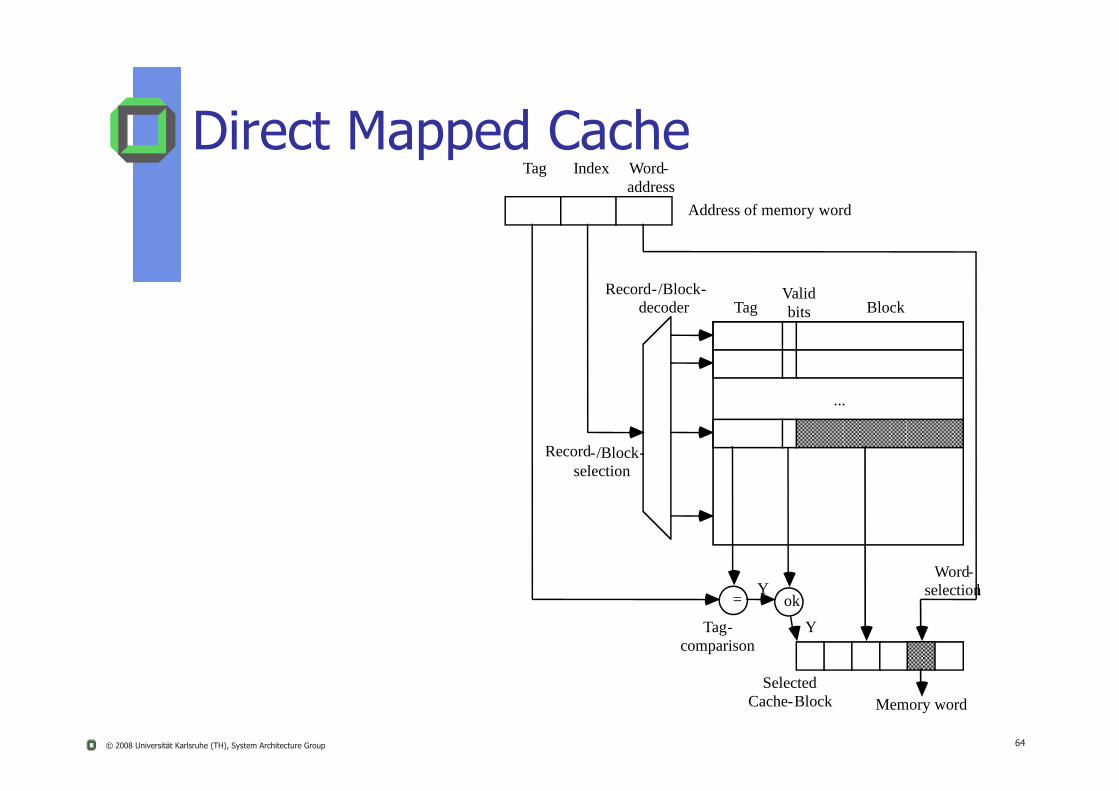
Direct Mapped CacheTag Index Word-
address
Record-/Block-decoder Tag
Validbits Block
Address of memory word
© 2008 Universität Karlsruhe (TH), System Architecture Group 64
Record-/Block-selection
...
= okY
Y
Memory word
Word-selectionl
Selected Cache-Block
Tag-comparison

N-Way Set Associative Cache
...
...
Associativity
Record[0]
Record[1]
Block-address
Block-Offset
Address of memory word
f
Record-decoder Block[0] Block[n-1]
x
© 2008 Universität Karlsruhe (TH), System Architecture Group 65
...
...
Record[s-1]
Word-selector
Memory word
Record-selection
Memory word -selection
Block-auswahl
Target Block
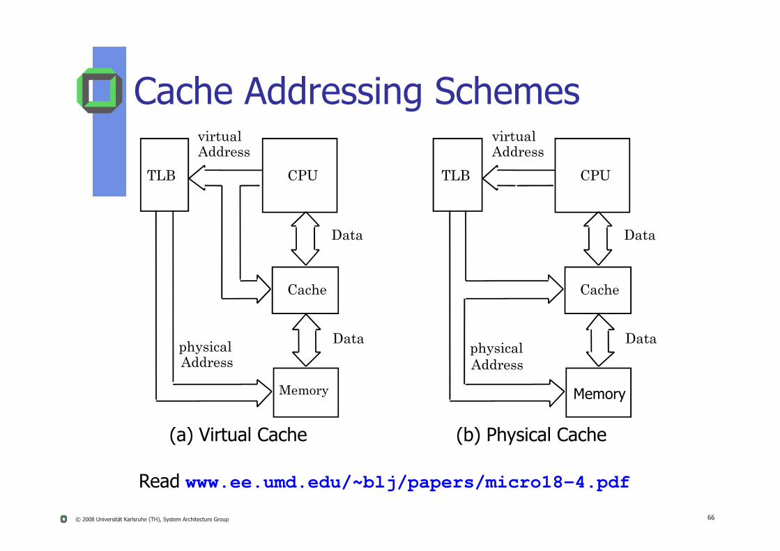
Cache Addressing Schemes
TLB CPU
virtualAddress
Data
TLB CPU
virtualAddress
Data
© 2008 Universität Karlsruhe (TH), System Architecture Group 66
(a) Virtual Cache (b) Physical Cache
Cache
Memory
physicalAddress
Data
Cache
Memory
physicalAddress
Data
Read www.ee.umd.edu/~blj/papers/micro18-4.pdf

Cache Memory Design
Cache Size Even mall caches have an impact on performance
Cache Line Size (Block size) Unit of data exchanged between cache and main memory
Principle of Location
© 2008 Universität Karlsruhe (TH), System Architecture Group 67
Unit of data exchanged between cache and main memory
Hit means the information was found in the cache
Larger block size better hit rate, until probability of using newly fetched data becomes less than the probability of reusing data that has been moved out of cache
Miss means data is not present in a cache line
Cache Memory Design
Mapping function determines cache location, a new block will
occupy
Replacement algorithm
Principle of Location
© 2008 Universität Karlsruhe (TH), System Architecture Group 68
p a a go determines the block, which has to be replaced
2 commonly used methods Least-Recently-Used (LRU) algorithm
FCFS (in victim caches)

Cache Memory Design
Write policy determines
when a block of cache is written to main memory
can occur every time a cache line is updated(write through policy)
Principle of Location
© 2008 Universität Karlsruhe (TH), System Architecture Group 69
(write-through policy)
can occur only when the cache line has to be replaced (write-back policy ) Minimizes main memory operation
Leaves main memory in an obsolete state
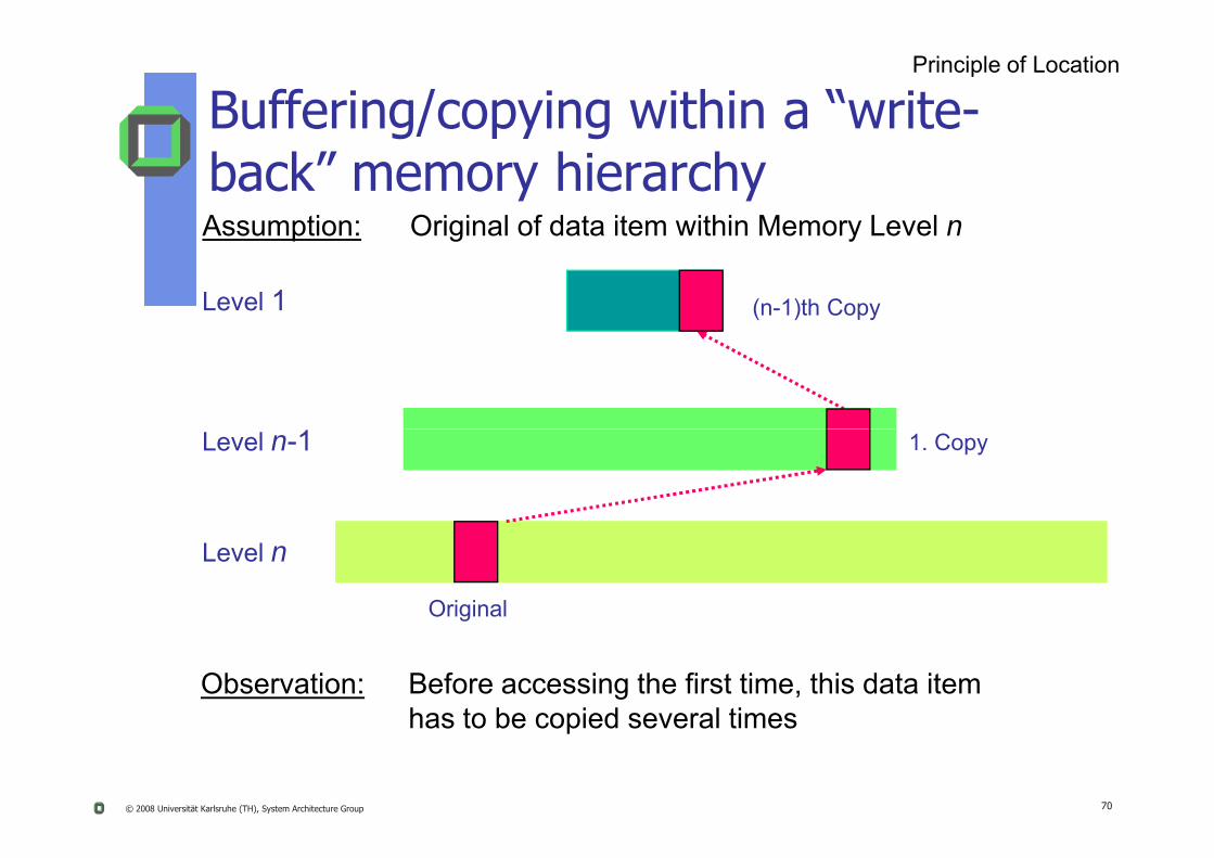
Assumption: Original of data item within Memory Level n
Level 1 (n-1)th Copy
Principle of Location
Buffering/copying within a “write-back” memory hierarchy
© 2008 Universität Karlsruhe (TH), System Architecture Group 70
Level n
Original
Level n-1 1. Copy
Observation: Before accessing the first time, this data item has to be copied several times

?
Level 1 Modification on this copy
Assumption: Original of data item within Memory Level n
Principle of Location
Buffering/copying within a “write-back” memory hierarchy
© 2008 Universität Karlsruhe (TH), System Architecture Group 71
Level n ?
?
Old Original
Level n-1 Old 1. Copy
Observation: Modifying a data item on the uppermost memory levelaffects data consistency.
?Level n-1
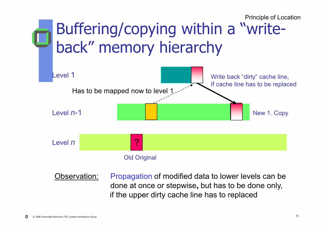
Level 1 Write back “dirty” cache line,If cache line has to be replaced
New 1. Copy
Has to be mapped now to level 1
Principle of Location
Buffering/copying within a “write-back” memory hierarchy
© 2008 Universität Karlsruhe (TH), System Architecture Group 72
Level n ?Old Original
Level n 1 e Copy
Observation: Propagation of modified data to lower levels can be done at once or stepwise, but has to be done only, if the upper dirty cache line has to replaced
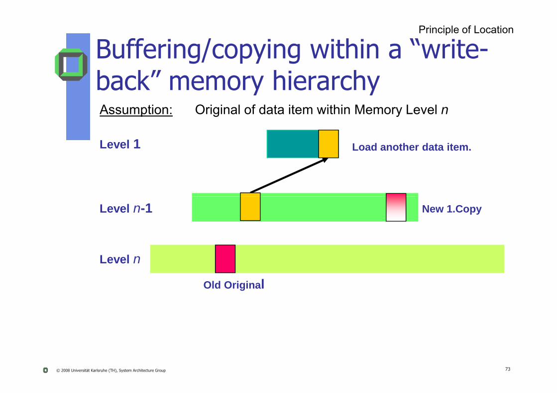
Level 1 Load another data item.
Assumption: Original of data item within Memory Level n
Principle of Location
Buffering/copying within a “write-back” memory hierarchy
© 2008 Universität Karlsruhe (TH), System Architecture Group 73
Level n
Old Original
Level n-1 New 1.Copy

Cache 1
Main Memory
Cache 2
Branching Memory Hierarchy
Principle of Location
© 2008 Universität Karlsruhe (TH), System Architecture Group 74
Disk Memory
Archive Memory Archive Memory
Questions: Why 2 archive memories? Additional levels with similar branches? Additional consistency problems?
Specific Literature
J. Liedtke „Caches Versus Object Allocation“,In 5th IEEE International Workshop on Object-Orientation in Operating Systems (IWOOOS), Seattle, WA, October 1996.
Principle of Location
© 2008 Universität Karlsruhe (TH), System Architecture Group 75
J. Liedtke „Potential Interdependencies between caches, TLBs, and memory management schemes“, Arbeitspapiere der GMD, No. 962, 1995

Memory Protection
OS must protect programs from each other and protect itself from buggy or malicious applications
Solution: Concept of Address Space
Simple scheme: HW offers base and limit register
Memory Protection
© 2008 Universität Karlsruhe (TH), System Architecture Group 76
Base register indicates begin of application’s memory space
Limit register indicates end of application’s memory space
Limitations: Memory must be allocated as a contiguous block
Might waste memory when program finishes
Does not allow applications to share memory directly Example: n copies of Mozilla share its program code in RAM

Address Space & Virtual Memory
OS creates a separate address space AS per application task or per system task
Assumption: almost each (part of an) AS is relocatible within the physical RAM
S ti ifi AS t f it h t b l t d
Virtual Memory
© 2008 Universität Karlsruhe (TH), System Architecture Group 77
Sometimes a specific AS or parts of it have to be located at specific physical addresses
System needs a HW address transformation unit (MMU) to translate efficiently logical “task” addresses into physical RAM addresses

Address Translation
Virtual AddressVirtual page address Offset-Address
Note:
Virtual Memory
© 2008 Universität Karlsruhe (TH), System Architecture Group 78
Physical Address
Physical frame address Offset-Address
Translation tableIn most VM systemsyou need at least one translation table per AS
Translation Table(s)
Translation often done using more than 1 translation table per AS, e.g.
Segment- and page table (Intel)
Virtual Memory
© 2008 Universität Karlsruhe (TH), System Architecture Group 79
Multi-level page tables

Address Translation (Intel 80486)Logical address
Virtual address
PhysicaladdressSegment
base
Virtual Memory
© 2008 Universität Karlsruhe (TH), System Architecture Group 80
Descriptortable
Segmenttablebase Page
tabledirectory
Pagedirectory
base
Pagetable
Page
Main memoryProgram Segmentation Paging
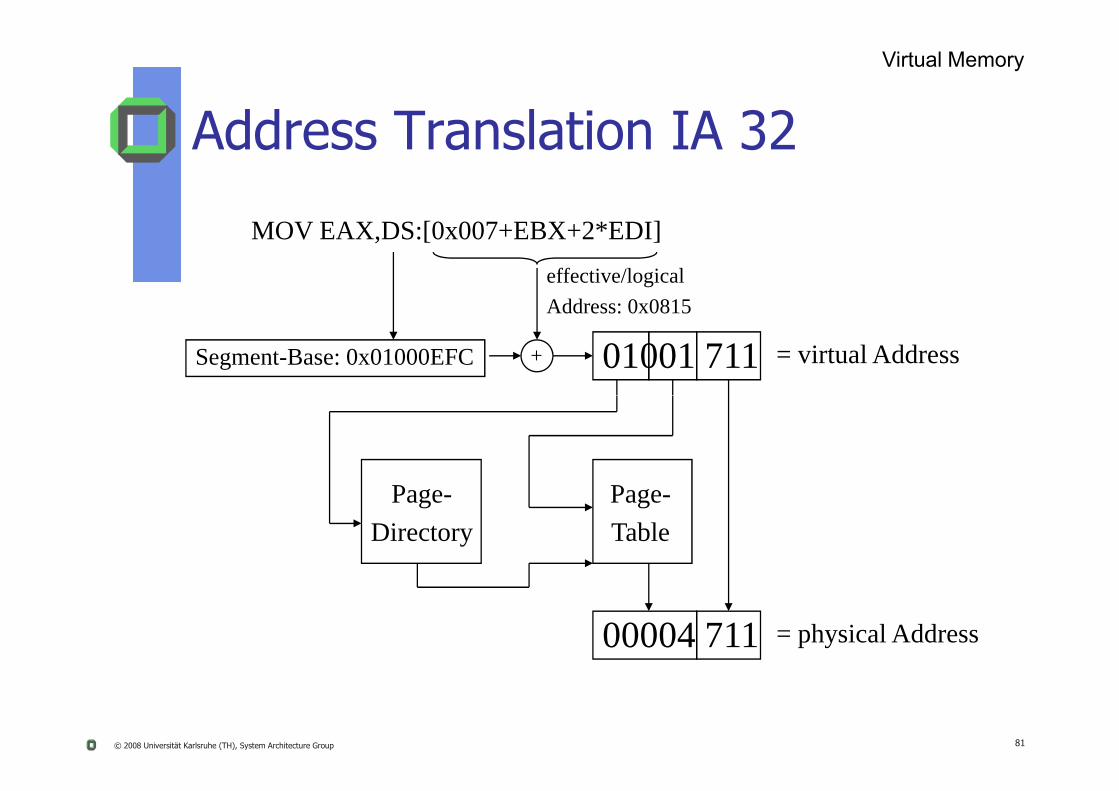
Address Translation IA 32
MOV EAX,DS:[0x007+EBX+2*EDI]effective/logicalAddress: 0x0815
Segment-Base: 0x01000EFC + 01001 711 = virtual Address
Virtual Memory
© 2008 Universität Karlsruhe (TH), System Architecture Group 81
Page-Directory
Page-Table
00004 711 = physical Address
Translation Look-Aside Buffer (TLB)
Parsing translation tables by software is slow
HW offers a quicker solution, e.g. TLB TLB contain the most recently used pairs of:
Virtual Memory
© 2008 Universität Karlsruhe (TH), System Architecture Group 82
Virtual page address, physical frame address,
TLB implementation via a associative cache
TLB sizes contain 32, 64 or even 128 entries
MMU contains TLB + some other control bit to enable quick access control
Interacting HW ComponentsInteracting HW Components
83© 2008 Universität Karlsruhe (TH), System Architecture Group

How do CPU & Peripherals interact?
Special (privileged) instructions
Interrupts
I/O-Peripherals
© 2008 Universität Karlsruhe (TH), System Architecture Group 84

I/O Control
How does OS initiate an I/O operation? Special instructions
in and out on x86 machines
Memory-mapped I/O Access hardware state as memory addresses
l dd /O b
© 2008 Universität Karlsruhe (TH), System Architecture Group 85
Requires MMU to translate certain addresses to I/O bus access Usually start I/O by writing a command to a HW register
Read block from disk at sector xyz into memory address 0815
How does OS realize that I/O has finished? Polling: read value from the result or status register of the
device Interrupt: Hardware signal that causes OS to get control and
run the corresponding interrupt handler

A WRITE system call transfers control to the printer driver (I/O program).
Printer driver prepares I/O
CPU waits for I/O to complete
I/O-Peripherals
© 2008 Universität Karlsruhe (TH), System Architecture Group 86
module for printing (4).
CPU has to WAIT for the print-operation to complete.
Printer driver finishes in (5) reporting status of I/O operation.

Exceptions and Interrupts
2 major classes of special situations Synchronous exception (e.g. trap) Asynchronous interrupt (e.g. end of DMA action)
additional differences concerning
Exception/Interrupt
© 2008 Universität Karlsruhe (TH), System Architecture Group 87
g Source Predictability Reproducibility
Handling exceptions or interrupts must be done in time and is processor specific
I/O-Peripherals
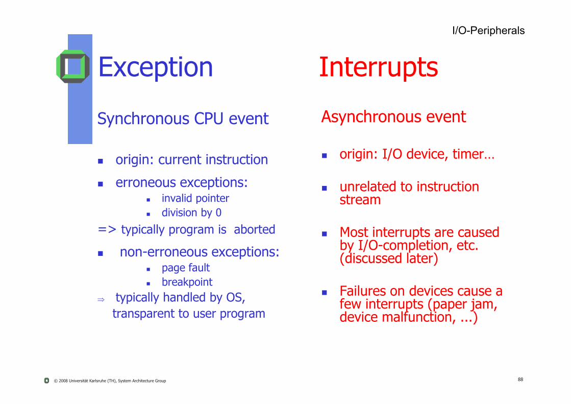
Exception Interrupts
Synchronous CPU event
origin: current instruction
erroneous exceptions: invalid pointer
Asynchronous event
origin: I/O device, timer…
unrelated to instruction stream
© 2008 Universität Karlsruhe (TH), System Architecture Group 88
a d po division by 0
=> typically program is aborted
non-erroneous exceptions: page fault breakpoint
typically handled by OS, transparent to user program
stream
Most interrupts are caused by I/O-completion, etc. (discussed later)
Failures on devices cause a few interrupts (paper jam, device malfunction, ...)
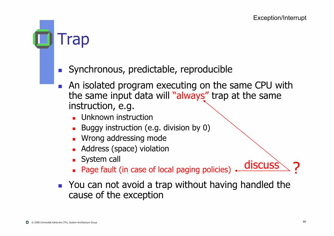
Trap
Synchronous, predictable, reproducible
An isolated program executing on the same CPU with the same input data will “always” trap at the same instruction, e.g. Unknown instruction
Exception/Interrupt
© 2008 Universität Karlsruhe (TH), System Architecture Group 89
Unknown instruction Buggy instruction (e.g. division by 0) Wrong addressing mode Address (space) violation System call Page fault (in case of local paging policies)
You can not avoid a trap without having handled the cause of the exception
?discuss

Interrupt
Asynchronous, not predictable, not reproducible
A peripheral device signals an interrupt to the CPU independently of the state of the currently running program on the CPU, e.g.
Exception/Interrupt
© 2008 Universität Karlsruhe (TH), System Architecture Group 90
p g , g Signaling external events (e.g. a sensor)
End of a DMA operation
End of an I/O operation (e.g. disk transfer)

Example: Trap or Interrupt?
#include <stdlib.h>float frandom () {return random()/random();
}
Exception/Interrupt
© 2008 Universität Karlsruhe (TH), System Architecture Group 91
chance that the executing process does a division by 0, this happens synchronously if it happens, however
it is not predictable when it will happen, but it is predictable where it will happen
It is an exception

Exception or Interrupt Handling
Potentially raising events: Signal from peripheral devices, e.g.
End of disk input
Timer signal from a watch dog
Switching the protection domain (in case of a system call)
Exception/Interrupt
© 2008 Universität Karlsruhe (TH), System Architecture Group 92
Switching the protection domain (in case of a system call)
Programming errors (invalid address)
Memory overflow (e.g. stack overflow in case of an endless recursion)
Paging on demand (in case of a page fault)
Alarm signals from your HW (e.g. shortage of energy)
The corresponding event handling has to be done during execution of the currently running program

Typical Interrupt TimelineDelay of interrupt handling
© 2008 Universität Karlsruhe (TH), System Architecture Group 93

Models of Event Handling
Resumption model Having handled the event, the interrupted program can resume its
execution at the same instruction pointer
Termination (aborting) model If the cause of a event cannot be handled severe error, i.e. the
interrupted program has to be terminated
Exception/Interrupt
© 2008 Universität Karlsruhe (TH), System Architecture Group 94
interrupted program has to be terminated
Raising an exception or an interrupt involves a context switch Currently running program exception handler or
Currently running program interrupt handler
We have to save the “context” of the interrupted program, otherwise no resumption
Goal: reduce overhead of saving and restoring contexts

Timing Effects
Handling of each exception and of each interrupt slows down the execution of the interrupted program
However, the result of a correct program is not endangered, but
Exception/Interrupt
© 2008 Universität Karlsruhe (TH), System Architecture Group 95
Real-time applications can fail
Hint:In any case, each programmer should not rely on anytiming conditions

Interrupt Control Interrupts happen at any time cause problems in the kernel
User code is in the middle of modifying state shared with other programs
OS is been in the middle of performing a time-sensitive operation E.g. zeroing out a newly allocated buffer of memory to pass to an
application OS and hardware must support synchronization of concurrent
activities
© 2008 Universität Karlsruhe (TH), System Architecture Group 96
Atomic operations: short sequences of instructions that can not be interrupted
e.g. READ-MODIFY-WRITE changes a variable in one atomic step One approach: disable interrupts during atomic operations
What are the problems with this approach?
Another approach: complex atomic instructions Test-and-set
Read value into register and store 1 into Load linked (LL) and store conditional (SC):
LL: load memory value into register SC: only perform store if the value at the address had not changed
since LL

Interrupts
Many computers permit I/O modules to interrupt an activity on the CPU
For this an I/O module just asserts an interrupt request line on the “control bus”
I/O-Peripherals
© 2008 Universität Karlsruhe (TH), System Architecture Group 97
Then CPU transfers control to an “Interrupt Handler” (normally part of the OS-kernel)
CPU can prevent to be interrupted, by masking out or disabling interrupts

Interrupt Handler
A (peripheral) interrupt interrupts the currently executing program invoking the corresponding interrupt handler
The interrupt handler might return* to the interrupted program
I/O-Peripherals
© 2008 Universität Karlsruhe (TH), System Architecture Group 98
interrupted program
Point of interruption can occur anywhere, so either HW or interrupt handler must save the state of the interrupted program (IP, PSW, registers ...) and restore it upon return
*What program may run instead of?

Long instructions can be interrupted
Interrupt Processing
I/O-Peripherals
© 2008 Universität Karlsruhe (TH), System Architecture Group 99
can be interrupted
Some CPUs save context into shadow registers

I/O program prepares I/O module, issues I/O command (to a printer)I/O program branches back to the user program, user code gets executed during I/O operation
Interrupts improving CPU usage
I/O-Peripherals
© 2008 Universität Karlsruhe (TH), System Architecture Group 100
(e.g. printing) no waiting
User program gets interrupted (x) when I/O operation is done and branches to interrupt handler to examine status of I/O moduleExecution of user code resumes

I/O-Peripherals
N>1 Interrupts: Sequential Order
© 2008 Universität Karlsruhe (TH), System Architecture Group 101
Analysis:Disable all interrupts during interrupt processing. Interrupts remain pending until CPU enables interrupts again. After interrupt handler completed, CPU checks for further pending interrupts
Low priorityinterrupt
High priorityinterrupt
I/O-Peripherals
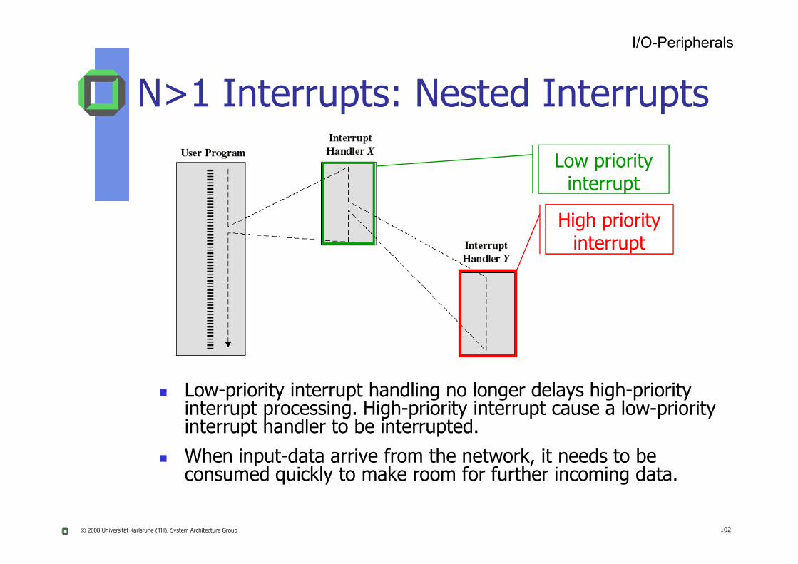
N>1 Interrupts: Nested Interrupts
© 2008 Universität Karlsruhe (TH), System Architecture Group 102
Low-priority interrupt handling no longer delays high-priority interrupt processing. High-priority interrupt cause a low-priority interrupt handler to be interrupted.
When input-data arrive from the network, it needs to be consumed quickly to make room for further incoming data.
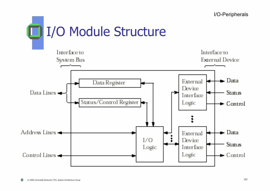
I/O Module Structure
I/O-Peripherals
© 2008 Universität Karlsruhe (TH), System Architecture Group 103
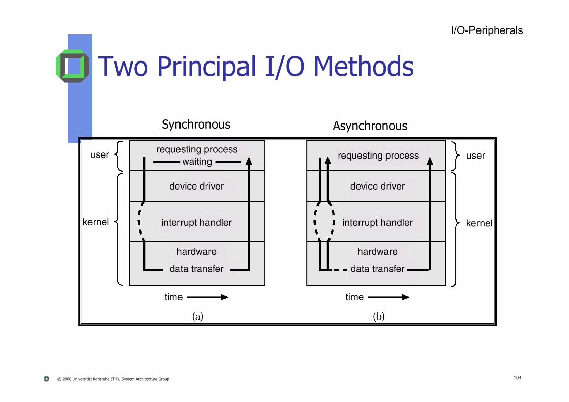
Two Principal I/O Methods
I/O-Peripherals
Synchronous Asynchronous
© 2008 Universität Karlsruhe (TH), System Architecture Group 104
I/O-Interface Techniques
I/O-Peripherals
Programmed I/O (polling)
Interrupt Driven I/O
© 2008 Universität Karlsruhe (TH), System Architecture Group 105
Discuss these techniques in detail in the tutorials!
Direct Memory Access (DMA)
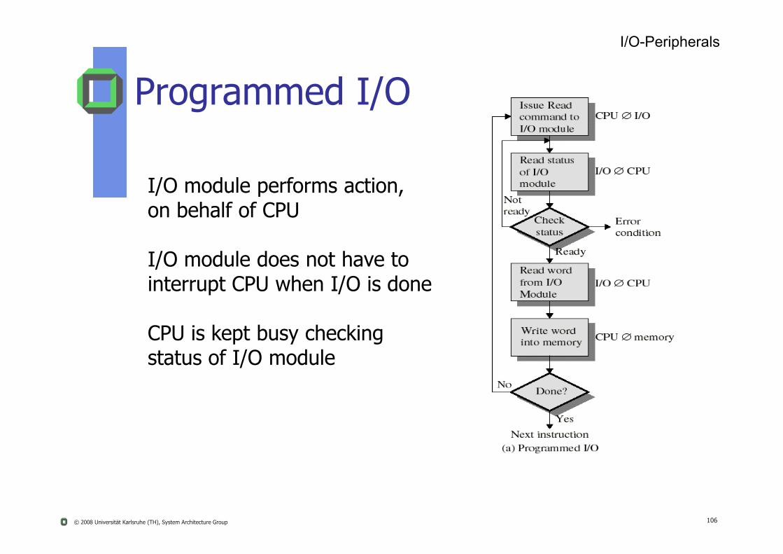
I/O module performs action, on behalf of CPU
I/O module does not have to i t t CPU h I/O i d
Programmed I/O
I/O-Peripherals
© 2008 Universität Karlsruhe (TH), System Architecture Group 106
interrupt CPU when I/O is done
CPU is kept busy checking status of I/O module

CPU is interrupted when I/O module is ready to transfer data, e.g. if requested operation finished.
CPU is free to do other work in the meantime no busy waiting
Interrupt-Driven I/O
I/O-Peripherals
© 2008 Universität Karlsruhe (TH), System Architecture Group 107
the meantime no busy waiting.Well-suited for medium-grained event.
Bad for frequent fine-grain events: high CPU costs per interrupt.
- Interrupt per incoming network packet might work
- Interrupt per byte is far too expensive.

CPU issues request to a DMA module (separate module or incorporated into I/O module)DMA module transfer a block of data directly to/from memory, not through CPU)Interrupt is sent when DMA is complete.
Direct Memory Access
I/O-Peripherals
© 2008 Universität Karlsruhe (TH), System Architecture Group 108
CPU is only involved at the beginning and at the end of the transfer, it is free to perform other jobs during data transfer.
However note:DMA may put heavy load on memory bus problem of cycle stealing

Main MemoryBuffer of
To access (either read or write) the desired buffer a device controller (e.g. a DMA) often only knows and needs physical addresses.
I/O-Peripherals
Physical Addressing of RAM
© 2008 Universität Karlsruhe (TH), System Architecture Group 109
4096
Controller
move (0815), 40960815
Example: Controller has to transfer a block to main memory
What may happen?
4096
Controller
Buffer of
move (0815), 40960815
Main MemoryMain Memory
I/O-Peripherals
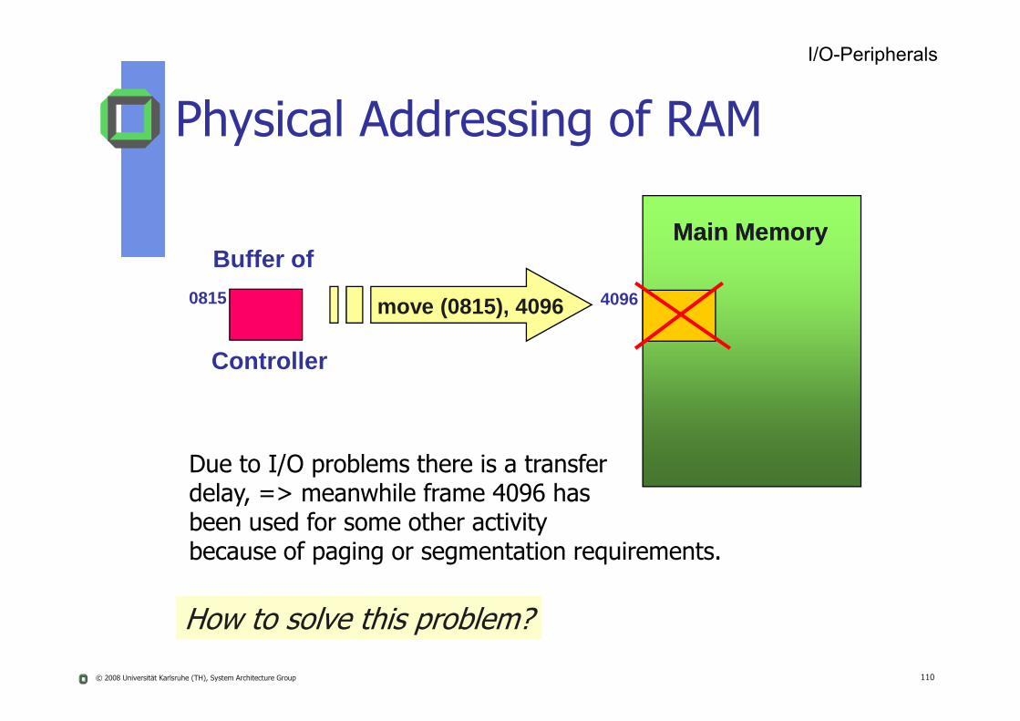
Physical Addressing of RAM
© 2008 Universität Karlsruhe (TH), System Architecture Group 110
Controller
Due to I/O problems there is a transfer delay, => meanwhile frame 4096 has been used for some other activity because of paging or segmentation requirements.
How to solve this problem?

4096
Buffer of
move (0815), 40960815
Main Memory
I/O-Peripherals
Physical Addressing of RAM
© 2008 Universität Karlsruhe (TH), System Architecture Group 111
Controller
“Pinning this frame”, i.e. as long as DMA transfer is not yet completed, this frame cannot be used otherwise!
Pinning and unpinning are the required mechanism.
What policy can you establish upon it?
Application of Pinning
To support DMA
To support real-time tasks (see*) Can that method be abused?
I/O-Peripherals
© 2008 Universität Karlsruhe (TH), System Architecture Group 112
Think about a solution
*J. Liedtke, V. Uhlig, K. Elphinstone, T. Jaeger, and Y. Park:
“How to Schedule Unlimited Memory Pinning of Untrusted Processesor Provisional Ideas About Service-Neutrality”
7th Workshop on Hot Topics in Operating Systems (HotOS), Rio Rico, MA, March 1999
I/O DevicesI/O Devices
113© 2008 Universität Karlsruhe (TH), System Architecture Group

I/O-Peripherals
HW Review (Disk)
© 2008 Universität Karlsruhe (TH), System Architecture Group 114
Structure of a disk drive
Summary I/O Management
Early computers had a static hardware configuration All I/O devices known at boot time Kernel was configured statically by the system administrator for the
particular machine
Today things are more complicated There are hotplug devices USB, Compact Flash, Firewire, etc.
© 2008 Universität Karlsruhe (TH), System Architecture Group 115
Even the PCI bus is configured on each boot cycle Assign I/O addresses, interrupt lines to each device at boot time Allows users to plug in new boards without reconfiguring the kernel
OS must discover available devices (even on the fly) USB controller interrupts OS when a device is added or removed Device identifies itself with a special identifier
Vendor/device ID, device type, etc. Kernel loads appropriate driver
Loadable kernel modules (Linux) User’s access to the device is enabled
Remap /dev/mouse to the new USB mouse device


![Multi-Service Broadband Network Architecture Evolution · 2019-06-24 · Multi-service Broadband Architecture defined in TR-144 [3], TR-145 [4] and WT-178 [9]. 2 Main Challenges for](https://img.dokumen.tips/doc/110x75/5e78d693d2cbad52f62fac12/multi-service-broadband-network-architecture-evolution-2019-06-24-multi-service.jpg)