Embed Size (px)
Citation preview
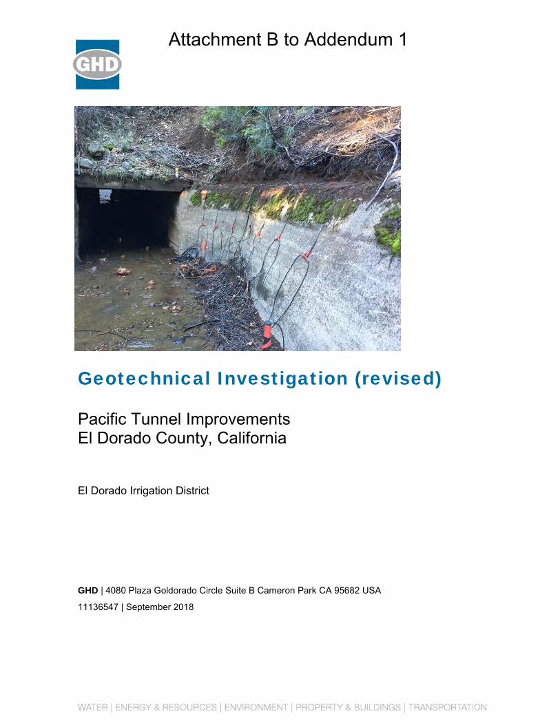
Geotechnical Investigation (revised)
Pacific Tunnel Improvements El Dorado County, California
El Dorado Irrigation District
GHD | 4080 Plaza Goldorado Circle Suite B Cameron Park CA 95682 USA
11136547 | September 2018
Attachment B to Addendum 1

GHD | Geotechnical Investigation | 11136547 | Page i
September 27, 2018
Cary Mutschler, PE El Dorado Irrigation District 2890 Mosquito Road Placerville, California 95667
RE: Geotechnical Investigation, Pacific Tunnel (revised)
GHD is pleased to present the attached report containing the results of our geotechnical investigation for the proposed Pacific Tunnel Improvements project in El Dorado County, California. It is our understanding that the proposed project consists of lining the tunnel and the construction of wingwalls at the upstream and downstream portals. This report supersedes our previous geotechnical investigation report dated February 6, 2017.
The accompanying report presents our findings, conclusions, and recommendations developed from our geotechnical investigation. Contained in the report are geotechnical design criteria and recommendations for design and construction of the proposed improvements. The results of the subsurface exploration and laboratory testing programs, which form the basis of our recommendations, are also included in the report. On the basis of our investigation, the site is suitable, from a geotechnical perspective, to receive the planned improvements provided the recommendations presented in the report are incorporated into the design and construction of the project.
If you have any questions regarding the information contained in this report, or if we may be of further assistance, please do not hesitate to contact us.
Sincerely,
GHD
Christopher D. Trumbull, P.E., G.E., D.GE Senior Geotechnical Engineer
GHD | Geotechnical Investigation | 11136547 | Page ii
Table of Contents
1. Introduction 5
1.1 Project Description ............................................................................................................. 5
1.2 Purpose and Scope of Work .............................................................................................. 5
2. Field Exploration and Laboratory Testing 5
2.1 Field Exploration ................................................................................................................ 5
2.2 Geotechnical Laboratory Testing ....................................................................................... 6
3. Geologic and Subsurface Conditions 7 3.1 Site Conditions ................................................................................................................... 7
3.2 Geologic Conditions ........................................................................................................... 7
3.3 Subsurface Conditions ....................................................................................................... 7
3.3.1 Subsurface Materials ........................................................................................ 7 3.3.2 Groundwater Conditions ................................................................................... 7
4. Conclusions 7
4.1 Ground Shaking ................................................................................................................. 7
5. Recommendations 8
5.1 Site Preparation and Earthwork ......................................................................................... 8 5.1.1 General Subgrade Preparation ......................................................................... 8 5.1.2 Engineered Fill .................................................................................................. 8 5.1.3 Benching and Keying Fills ................................................................................ 9 5.1.4 Compaction ....................................................................................................... 9 5.1.5 Cut Slopes ........................................................................................................ 9 5.1.6 Fill Slopes ......................................................................................................... 9
5.2 Foundations ....................................................................................................................... 9
5.2.1 Wingwall Footings........................................................................................... 10 5.2.2 Passive Resistance ........................................................................................ 10
5.3 Rock Anchors ................................................................................................................... 10
5.4 Lateral Earth Pressures ................................................................................................... 11
5.5 Construction Observation ................................................................................................ 11
6. References 11
7. Limitations 12
Table Index
Table 5.1.2 Import Fill Specifications .................................................................................................... 8
Table 5.2 Foundation Soil Parameters…………………………………………………………………....9
GHD | Geotechnical Investigation | 11136547 | Page iii
Table 5.2.1 Bearing Capacity……………………………………………………………………………10
Appendix Index Appendix A Figures
Appendix B Logs of Test Pits
Appendix C Geotechnical Laboratory Test Results
Appendix D Seismic Refraction Survey Results
Appendix E Tunnel Condition Assessment
GHD | Geotechnical Investigation | 11136547 | Page iv
Distribution
To: El Dorado Irrigation District
El Dorado Irrigation District
2890 Mosquito Road
Placerville, California 95667
From: GHD
Christopher Trumbull, P.E., G.E., D.GE
4080 Plaza Goldorado Circle, Suite B
Cameron Park, CA 95682
GHD | Geotechnical Investigation | 11136547 | Page 5
1. Introduction
This report presents the findings, conclusions, and recommendations developed from our geotechnical engineering investigation. The investigation was conducted in accordance with the Professional Services Agreement *On-Call Contract – Geotechnical Notice to ProceedN1216-291 dated 12/05/16. This report supersedes our previous geotechnical investigation report dated February 6, 2017.
1.1 Project Description
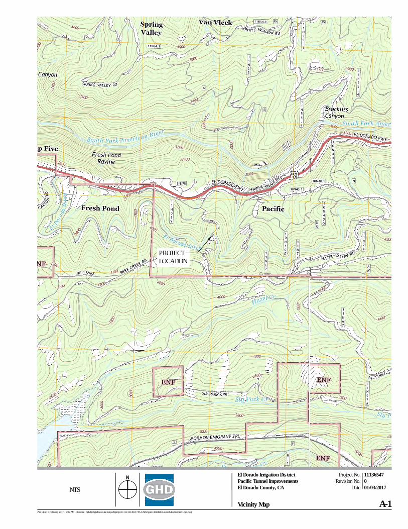
The project site is located south of US Highway 50 in El Dorado County, California as shown on Figure A-1. The proposed project consists primarily of the design and construction of new tunnel lining and wingwalls at both the upstream and downstream portals.
1.2 Purpose and Scope of Work
The purpose of this study was to evaluate the suitability of the project site, from a geotechnical perspective, for the proposed improvements. The main objectives of the investigation were to characterize the subsurface materials, perform engineering analyses, develop geotechnical recommendations and criteria, and document our findings, conclusions, and recommendations in this report.
The scope of our geotechnical investigation included the following tasks:
• A review of published geologic and geotechnical material pertaining to the site vicinity
• A field exploration program consisting of two test pits to a depth of approximately 2 feet below ground surface within the site to characterize the subsurface conditions
• Three seismic refraction surveys to characterize the subsurface materials
• Geotechnical laboratory testing on select soil samples collected from the test pits
• Engineering analyses to develop geotechnical design criteria and recommendations for the proposed project
• Preparation of this report
2. Field Exploration and Laboratory Testing
2.1 Field Exploration
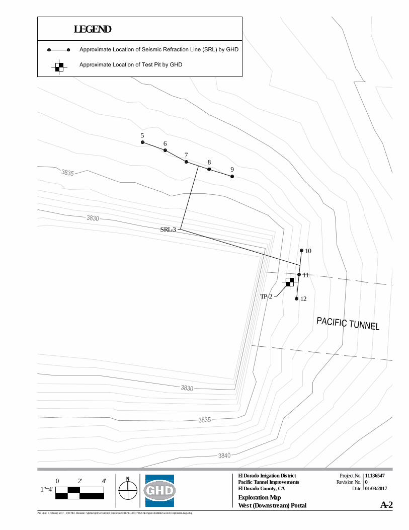
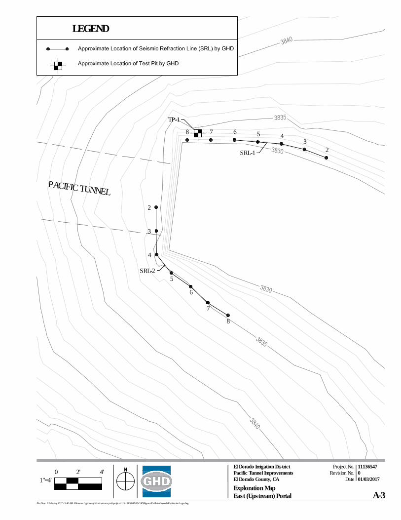
Two test pits were hand excavated on December 22, 2016 at the approximate locations shown on the Exploration Maps, Figures A-2 and A-3. The test pits were placed near the proposed wing wall improvements and were located in the field based on estimated distances from the existing structures. The test pits were excavated to a maximum depth of approximately 2 feet under the supervision of Christopher Trumbull of GHD.
GHD | Geotechnical Investigation | 11136547 | Page 6
GHD performed three seismic refraction surveys of the existing site; see Figure A-2 in Appendix A for locations. Lines one and two were performed at the upstream portal. Line three was performed in two legs perpendicular to each other at the downstream portal. The lines were based on site improvements, existing conditions, and landslide geometry. The purpose of the surveys was to provide additional subsurface data related to seismic velocity and depth of rock to assist in evaluating the strength of rock for foundation and anchor design.
The seismic refraction lines were acquired using a 12-channel system with geophones spaced at 2-foot intervals to provide adequate detail of the subsurface refractors, and the energy source consisted of an impact tool (16-lb sledge hammer). Shot points were positioned midpoint between each geophone along the length of the line. Seismic data was acquired utilizing a digital, distributed, 24-bit instrument. Color-coded seismic velocity cross-sections were generated for the seismic refraction lines to clearly delineate changes in seismic velocities.
Seismic refraction has its limitations and shall coincide with other methods, such as geotechnical borings, and geological observations. General and specific limitations are listed in ASTM D5777.
Subsurface conditions encountered are summarized in Section 3.3. Logs of the test pits were prepared based on the field logging, visual examination of the soil samples in the laboratory, and the results of laboratory testing. The soil test pit key and the logs of test pits are presented in Appendix B. The results of the seismic refraction surveys are presented in Appendix D.
2.2 Tunnel Inspection
A tunnel inspection was performed on December 22, 2016. The objective of the inspection was to observe and evaluate the current condition of Pacific Tunnel. To achieve this objective, the inspection party performed the condition assessment, including rebound hammer testing, geologic interpretation of the tunnel condition, identification of anomalies, measurement of cross-sectional dimensions, measurement of seeps and water inflow, and photography of conditions. The Tunnel Condition Assessment is presented in Appendix E.
2.3 Geotechnical Laboratory Testing
Laboratory testing was conducted on disturbed soil samples recovered during the site investigation. Samples were classified in general accordance with ASTM D2487. Tests conducted include the following:
• Standard Test Method for Particle-Size Analysis of Soils (ASTM D422)
• Standard Test Method for Laboratory Compaction Characteristics of Soil (ASTM D1557)
• Standard Test Method for Direct Shear Test of Soils (ASTM D3080)
Geotechnical laboratory test results are presented in Appendix C.
GHD | Geotechnical Investigation | 11136547 | Page 7
3. Geologic and Subsurface Conditions
3.1 Site Conditions
The project is located in El Dorado County, California. The Pacific Tunnel is an approximately 190-foot-long untreated water tunnel in El Dorado Irrigation District’s (EID’s) water delivery system. The tunnel conveys flow along the El Dorado Canal (FERC Project 184) below access road R82. The access road to the tunnel from Park Creek Road consisted of steep grades with erosion, rilling in areas were greater than 12-inches in depth. The approximate 190-foot long tunnel (nominal) is unlined rock over much of its length, with timber lined sections at the inlet and outlet portals. The upstream and downstream portals consist of soil slopes ranging from 2:1 to 1:1 (H:V) with timber cribbing.
3.2 Geologic Conditions
The site is located within the foothills of the Sierra Nevada geomorphic province. The site is mapped as Tertiary aged Mehrten Formation (Wagner, 1981). Mehrten is a conglomerate or breccia matrix composed of volcanic rocks.
3.3 Subsurface Conditions
3.3.1 Subsurface Materials
The subsurface materials encountered in the investigation consisted of brown and red brown silty sand with gravel to the maximum depth explored of 2 feet. These soils were underlain by Mehrten Formation volcanics. Detailed descriptions of the materials encountered in the test pits are presented in the test pit logs in Appendix B.
3.3.2 Groundwater Conditions
Groundwater was not encountered in the investigation. The depth of groundwater is expected to vary over time due to seasonal changes and other factors such as changes to site drainage.
4. Conclusions
On the basis of our investigation, the site is suitable, from a geotechnical perspective, to receive the planned improvements provided the recommendations presented in the report are incorporated into the design and construction of the project.
4.1 Ground Shaking
The site vicinity is located in an area generally characterized as having low seismicity. Using the USGS Seismic Hazard Tool Website considering the site location, ASCE 7-10/NEHRP, and Type D soils, the Peak Ground Acceleration (PGA) is 0.22 g. Strong ground shaking at the site should not be expected during an earthquake.
GHD | Geotechnical Investigation | 11136547 | Page 8
4.2 Expansive Soils
Expansive soils are defined as soils that undergo large volume changes (shrink or swell) due to variations in moisture content. Such volume changes may cause damaging settlement and/or heave of foundations, slabs-on-grade, pavements, etc. No evidence of expansive soil was discovered during the subsurface exploration for this project (i.e. soils with a liquid limit greater than 50 or a plasticity index greater than 25).
4.3 Existing Utilities
No underground utilities were discovered during the field exploration and tunnel inspection, though utility field locating was outside of the Project scope. A utility locating investigation would need to be conducted to provide a greater understanding of the potential underground utilities affecting the site
5. Recommendations
5.1 Site Preparation and Earthwork
General site preparation should include the stripping of the existing pavement section. Abandoned underground structures such as culverts should be removed and replaced with engineered fill, placed and compacted as recommended in Section 5.1.4..
5.1.1 General Subgrade Preparation
Any soft, loose areas should be stabilized prior to placement of engineered fill, foundations, pavements, or other structures.
5.1.2 Engineered Fill
Engineered fill should consist of a homogenous mixture of soil and rock free of vegetation, organic material, and rubble. Although not anticipated, highly plastic or organic soils found on site should not be used as engineered fill material.
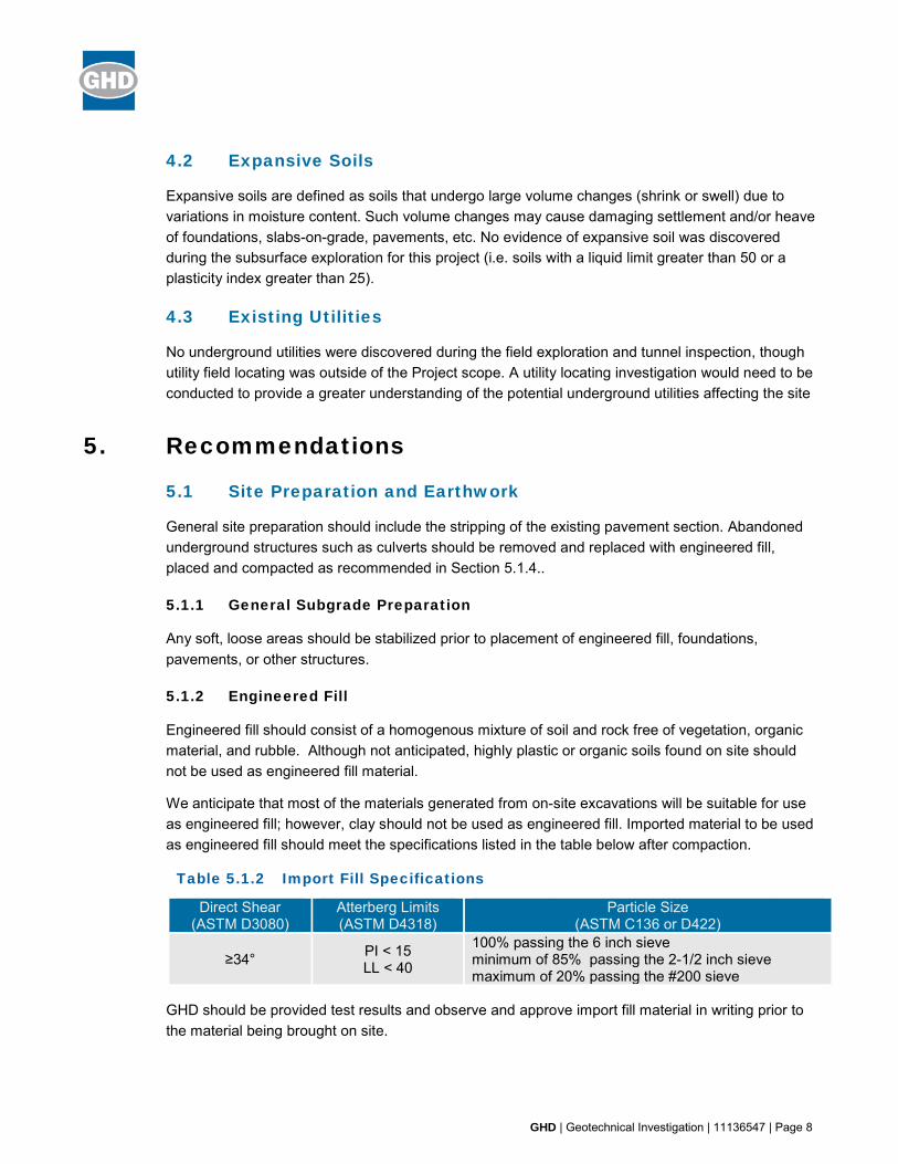
We anticipate that most of the materials generated from on-site excavations will be suitable for use as engineered fill; however, clay should not be used as engineered fill. Imported material to be used as engineered fill should meet the specifications listed in the table below after compaction.
Table 5.1.2 Import Fill Specifications
Direct Shear (ASTM D3080)
Atterberg Limits (ASTM D4318)
Particle Size
(ASTM C136 or D422)
≥34° PI < 15 LL < 40
100% passing the 6 inch sieve minimum of 85% passing the 2-1/2 inch sieve maximum of 20% passing the #200 sieve
GHD should be provided test results and observe and approve import fill material in writing prior to the material being brought on site.

GHD | Geotechnical Investigation | 11136547 | Page 9
5.1.3 Benching and Keying Fills
Slopes with inclinations of 6:1 or steeper should be benched during placement of engineered fill. The benches should consist of a level surface excavated at least 4 feet horizontally into native subgrade. The benches should continue progressively up the slope at vertical increments of not greater than 3 feet. Fill placed on slopes that are steeper than 4:1 should be keyed into firm native soil or weathered rock at the toe of the fill slope. The bottom of the keyway should extend a minimum of 3 feet below downslope grade and a have a minimum width of 10 feet (extending beneath the toe of the fill slope). Subdrainage of the keyways may be necessary and should be determined by a qualified GHD representative in the field at the time of construction.
5.1.4 Compaction
Engineered fill should be moisture conditioned as necessary, placed in horizontal loose lifts not exceeding 8 inches in thickness, and compacted to a minimum of 90 percent of the maximum dry density as determined by ASTM D1557 for fills less than 5 feet in thickness. In areas to receive canal improvements, or fills thicker than 5 feet, fill should be compacted to 95 percent of the maximum dry density as determined by ASTM D1557. Placement of fill material should be verified by a qualified geotechnical representative on a continuous basis. Nuclear density testing should be performed every two vertical feet of backfill placement.
5.1.5 Cut Slopes
Cut slopes at the portals should be excavated as not to exceed a 2:1 (H:V) inclination in native soil, or 1:1 in rock. A v-ditch should be constructed at the perimeter to prevent water from entering the cut slope area.
5.1.6 Fill Slopes
Fill slopes should be constructed at an inclination no steeper than 2:1, should be laterally over-built at least one foot, and the slope face trimmed back to firm, compacted material
5.1.7 Erosion Control
Erosion control measures should be implemented for exposed surfaces potentially subject to soil erosion particularly cut and fill slopes. Best Management Practices to reduce erosion and transport of soil particles or turbid water into the drainage course flowing from the construction site must be employed. All conditions of existing water quality regulatory agency permits must be adhered to.
5.2 Foundations
Provided herein are the soil parameters to be used for the foundations and retaining walls. The parameters are based on materials encountered in the test pits, laboratory testing of collected samples (See Appendix B and D) and engineering judgement.

GHD | Geotechnical Investigation | 11136547 | Page 10
Table 5.2 Foundation Soil Parameters
Parameters Soil Rock Unit Weight (pcf), γt 93 150
Internal Friction Angle, ø 34 40 Cohesion (psf), c 0 0
5.2.1 Wingwall Footings
Footings for the new portal wingwalls should be designed with maximum allowable bearing capacities in Table 5.2.1 below. The allowable bearing capacity can be increased by one-third for all loads including wind and seismic. The proposed footings should be excavated to a minimum depth of 18 inches below the lowest adjacent grade and have a minimum width of 24 inches. Total settlement should be less than 1 inch and differential settlement across the structure should be less than 1/2 inch.
Table 5.2.1 Maximum Allowable Bearing Capacity
Bearing Material Bearing Capacity (psf) Dead Load Dead + Live Loads
Soil 2,300 3,500 Rock 4,000 6,000
5.2.2 Passive Resistance
Passive earth resistance or passive earth pressure is the amount of resistance provided by the soil in response to a movement of a structure resulting in a compressive force upon the soil. A passive earth pressure of 350 pounds per cubic foot should be used if the upper foot of soils is ignored. A friction coefficient of 0.35 is recommended. If the foundation is poured against neatly excavated soil without the use of forms, both the friction coefficient and the passive resistance may be used in design. Passive earth pressures provided herein assume that the zone of interest is above groundwater table and on a relatively level surface. If these conditions are not met in any of the foundation locations, GHD should be contacted to provide a reduced passive earth pressure value.
5.3 Rock Anchors
To achieve stability of the wingwalls, permanent rock anchors may be required. Rebound hammer readings within the tunnel ranged from 200 psi to 4,150 psi with an average reading of approximately 2,000 psi. Considering the rebound hammer values and the seismic velocities, an allowable bond strength of 200 psi (10% of the ultimate capacity) should be used for design.
Rock anchors shall be 1”, 150 ksi epoxy coated all-thread bar. A non-shrink cement grout such as Masterflow 555 grout or equivalent is recommended. The grout should be mixed in accordance with
GHD | Geotechnical Investigation | 11136547 | Page 11
the manufacturer’s specifications and tremmied from the bottom of the anchor hole. Grout cylinders 2 inches in diameter and 4 inches long should be cast at the time of grouting. For each day’s grouting, cylinders will be broken at 24 hours, 2 days, 7 days, and 2 at 28 days (with one hold, e.g. collect 6 samples). Stressing of rock anchors may commence once the grout has achieved a compressive strength of 2,000 psi.
Proof testing of rock anchors should be accomplished by applying a sustained proof load to a rock anchor and measuring anchor movement over a specified period of time. A minimum of 15 percent of the anchors should be proof tested to a minimum of 133 percent of the design capacity. A load cell capable of providing a capacity of two times the design capacity of the anchors should be used. The load cell should have been calibrated by a certified laboratory within the last six months, and the certificate should be submitted to GHD prior to testing.
5.4 Lateral Earth Pressures
We assume the wingwalls will be in a restrained (at-rest) and undrained condition. An undrained at-rest equivalent fluid pressure of 85 pcf should be used for design.
5.5 Invert Slab
Due to the probe depth measured at the invert in the tunnel condition assessment, it is recommended that the tunnel receive an invert slab to reduce future erosion and improve flow through the tunnel.
5.6 Tunnel Liner
Due to the scour observed at the ribs in the tunnel condition assessment, and to improve flow characteristic to accommodate for future flows, it is recommended that the tunnel receive lining of the ribs with reinforced air-placed concrete. The Mehrten rock that comprises the tunnel ribs and back may be considered equivalent to un-reinforced concrete with an unconfined compressive strength of 2,000 pounds per square inch (psi) for design.
5.7 Construction Observation
Our conclusions and recommendations are contingent upon GHD being retained to provide intermittent observation and appropriate field and laboratory testing during site preparation to evaluate if the subsurface conditions are as anticipated. If the subsurface conditions are observed to be different from those described in this report, we should be notified immediately so that the changed conditions can be evaluated and our recommendations revised, if appropriate. The recommendations in this report are contingent upon our notification and review of changed conditions. The services proposed above would be performed on an as-needed basis under a supplemental task order.
6. References
Wagner, et all. 1981. “Geologic Map of the Sacramento Quadrangle, California, 1:250,000”

GHD | Geotechnical Investigation | 11136547 | Page 12
Jennings, Charles W. 2010. “Geologic Map of California: California Division of Mines and Geology, scale 1:750,000.”
Post-Tensioning Institute, 2014, “Recommendations for Prestressed Rock and Soil Anchors.”
California Building Standards Commission, 2016, “California Building Code.”
7. Limitations
This Geotechnical Investigation (“Report”):
• Has been prepared by GHD for the El Dorado Irrigation District (the District) under the professional supervision of those senior partners and/or senior staff whose seals and signatures appear herein
• May only be used and relied on by the District, which is responsible to ensure that all relevant parties to the project, including designers, contractors, subcontractors, etc., are made aware of this report in its entirety
• Must not be copied to, used by, or relied on by any person other than the District without the prior written consent of GHD
• May only be used for the purpose of engineering design of the proposed storm drain improvements at the project site described in this report (and must not be used for any other purpose)
GHD and its servants, employees and officers otherwise expressly disclaim responsibility to any person other than the District arising from or in connection with this Report.
To the maximum extent permitted by law, all implied warranties and conditions in relation to the services provided by GHD and the Report are excluded unless they are expressly stated to apply in this Report.
The services undertaken by GHD in connection with preparing this Report:
• In regard to site exploration and testing:
– Site exploration and testing characterizes subsurface conditions only at the locations where the explorations or tests are performed; actual subsurface conditions between explorations may be different than those described in this report. Variations of subsurface conditions from those analyzed or characterized in this report are not uncommon and may become evident during construction. In addition, changes in the condition of the site can occur over time as a result of either natural processes (such as earthquakes, flooding, or changes in ground water levels) or human activity (such as construction adjacent to the site, dumping of fill, or excavating). If changes to the site’s surface or subsurface conditions occur since the performance of the field work described in this report, or if differing subsurface conditions are encountered, we should be contacted immediately to evaluate the differing conditions to assess if the opinions, conclusions, and recommendations provided in this report are still applicable or should be amended.
GHD | Geotechnical Investigation | 11136547 | Page 13
• In regard to limitations:
– Our scope of services was limited to the proposed work described in this report, and did not address other items or areas.
– The geotechnical investigation upon which this report is based was conducted for the proposed structures at the project site described in this report. The conclusions and recommendations contained in this report are not valid for other structures and/or project sites. If the proposed project is modified or relocated, or if the subsurface conditions found during construction differ from those described in this report, GHD should be provided the opportunity to review the new information or changed conditions to determine if our conclusions and recommendations need revision.
• Did not include evaluation or investigation of the presence or absence of wetlands
• Did not include a landslide evaluation
• Did not include a fault investigation
GHD expressly disclaims responsibility for any error in, or omission from, this Report arising from or in connection with any of the Assumptions being incorrect. There is no warranty, either expressed or implied. GHD accepts no liability regarding completeness or accuracy of the information presented and/or provided to us, or any conclusions and decisions which may be made by the client or others regarding the subject site/project. Verification of our conclusions and recommendations is subject to our review of the project plans and specifications, and our observations of construction.
Subject to the paragraphs in this section of the Report, the interpretations of data, findings, conclusions, recommendations and professional opinions in this Report are based on the information reviewed, site conditions encountered, and samples collected during our field exploration and were developed in accordance with generally accepted geotechnical engineering principles and practices and as prescribed by the client. This Report is considered valid for the proposed project for a period of two years from the report date provided that the site conditions and development plans remain unchanged. With the passage of time, changes in the conditions of a property can occur due to natural processes or the works of man on this or adjacent properties. Legislation or the broadening of knowledge may result in changes in applicable standards. Depending on the magnitude of any changes, GHD may require that additional studies (at additional cost) be performed and that an updated report be issued. Additional studies may disclose information which may significantly modify the findings of this report. GHD will retain untested samples collected during our field investigation for a period not to exceed 60 days unless other arrangements are made with the client. After a period of two years from the report date, GHD expressly disclaims responsibility for any error in, or omission from, this Report arising from or in connection with those opinions, conclusions and any recommendations.
GHD | Geotechnical Investigation | 11110191 | Appendix A
Appendix A Figures
DateRevision No.
Project No.
Plot Date: 6 February 2017 - 9:39 AM Filename: \\ghdnet\ghd\us\cameron park\projects\111\11136547\06-CAD\Figures\Exhibits\Geotech Exploration Logs.dwg
El Dorado Irrigation DistrictPacific Tunnel ImprovementsEl Dorado County, CA
11136547001/03/2017
A-1Vicinity Map
PROJECTLOCATION
NTS
9
12
SRL-3
TP-2
11
10
87
65
DateRevision No.
Project No.
Plot Date: 6 February 2017 - 9:40 AM Filename: \\ghdnet\ghd\us\cameron park\projects\111\11136547\06-CAD\Figures\Exhibits\Geotech Exploration Logs.dwg
El Dorado Irrigation DistrictPacific Tunnel ImprovementsEl Dorado County, CA
11136547001/03/2017
LEGEND
Approximate Location of Test Pit by GHD
Approximate Location of Seismic Refraction Line (SRL) by GHD
0 4'1"=4'
2'
A-2Exploration MapWest (Downstream) Portal
23
45678
8
2
PACIFIC TUNNEL
SRL-2
SRL-1
TP-1
3
4
7
6
5
LEGEND
Approximate Location of Test Pit by GHD
Approximate Location of Seismic Refraction Line (SRL) by GHD
0 4'1"=4'
2'Date
Revision No.Project No.
Plot Date: 6 February 2017 - 9:40 AM Filename: \\ghdnet\ghd\us\cameron park\projects\111\11136547\06-CAD\Figures\Exhibits\Geotech Exploration Logs.dwg
El Dorado Irrigation DistrictPacific Tunnel ImprovementsEl Dorado County, CA
11136547001/03/2017
A-3Exploration MapEast (Upstream) Portal
GHD | Geotechnical Investigation | 11110191 | Appendix B
Appendix B Logs of Test Pits
El Dorado Irrigation DistrictPacific Tunnel ImprovementsEl Dorado County, CA
1113654702/6/2017
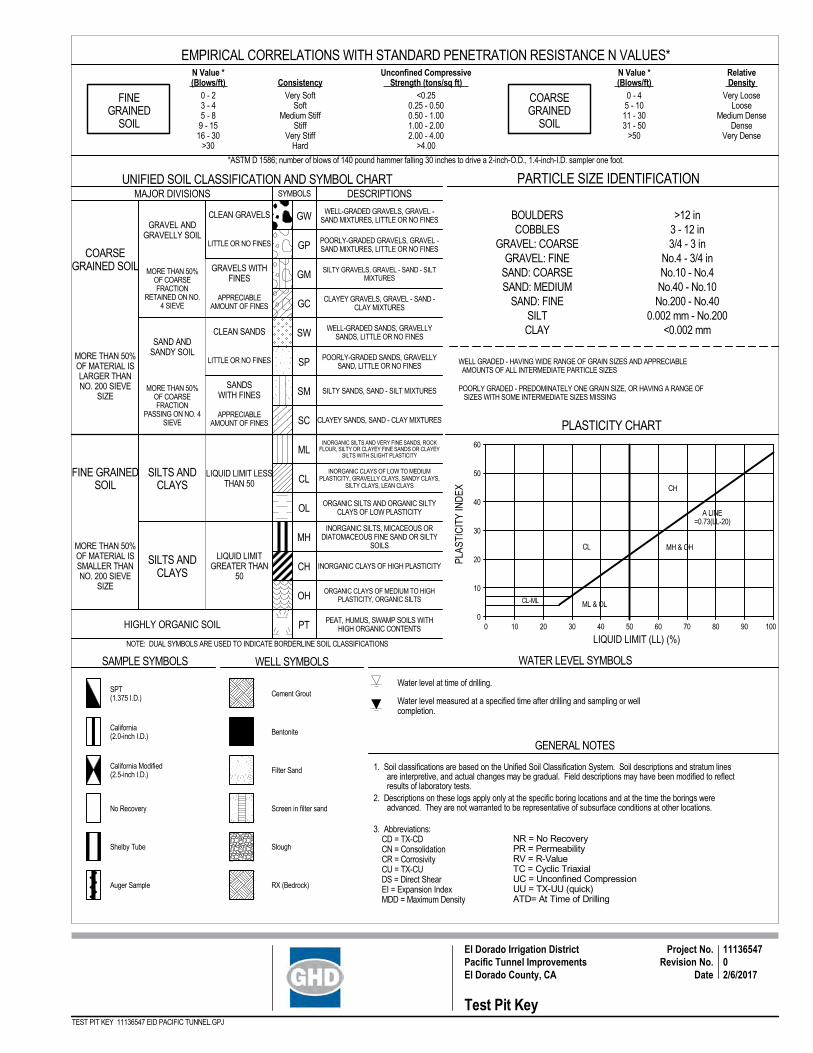
Test Pit Key
SYMBOLS
SANDSWITH FINES
WELL-GRADED GRAVELS, GRAVEL -SAND MIXTURES, LITTLE OR NO FINES
INORGANIC CLAYS OF LOW TO MEDIUMPLASTICITY, GRAVELLY CLAYS, SANDY CLAYS,
SILTY CLAYS, LEAN CLAYS
COARSEGRAINED SOIL
SAMPLE SYMBOLS
GENERAL NOTES
WELL SYMBOLS WATER LEVEL SYMBOLS
Water level measured at a specified time after drilling and sampling or wellcompletion.
Water level at time of drilling.
POORLY GRADED - PREDOMINATELY ONE GRAIN SIZE, OR HAVING A RANGE OF SIZES WITH SOME INTERMEDIATE SIZES MISSING
MORE THAN 50%OF MATERIAL ISSMALLER THANNO. 200 SIEVE
SIZE
APPRECIABLEAMOUNT OF FINES
LITTLE OR NO FINES
APPRECIABLEAMOUNT OF FINES
LITTLE OR NO FINES
GW
GP
GM
GC
SW
SP
SM
SC
ML
CL
OL
MH
CH
OH
PT
CLEAN SANDS
GRAVELS WITHFINES
CLEAN GRAVELS
LIQUID LIMITGREATER THAN
50
MORE THAN 50%OF MATERIAL ISLARGER THANNO. 200 SIEVE
SIZE
1. Soil classifications are based on the Unified Soil Classification System. Soil descriptions and stratum linesare interpretive, and actual changes may be gradual. Field descriptions may have been modified to reflectresults of laboratory tests.
2. Descriptions on these logs apply only at the specific boring locations and at the time the borings wereadvanced. They are not warranted to be representative of subsurface conditions at other locations.
NOTE: DUAL SYMBOLS ARE USED TO INDICATE BORDERLINE SOIL CLASSIFICATIONS
SILTS ANDCLAYS
LIQUID LIMIT LESSTHAN 50
POORLY-GRADED GRAVELS, GRAVEL -SAND MIXTURES, LITTLE OR NO FINES
BOULDERSCOBBLES
GRAVEL: COARSEGRAVEL: FINE
SAND: COARSESAND: MEDIUM
SAND: FINESILTCLAY
WELL GRADED - HAVING WIDE RANGE OF GRAIN SIZES AND APPRECIABLE AMOUNTS OF ALL INTERMEDIATE PARTICLE SIZES
UNIFIED SOIL CLASSIFICATION AND SYMBOL CHARTDESCRIPTIONS
MORE THAN 50%OF COARSEFRACTION
RETAINED ON NO.4 SIEVE
MORE THAN 50%OF COARSEFRACTION
PASSING ON NO. 4SIEVE
SILTS ANDCLAYS
FINE GRAINEDSOIL
CLAYEY GRAVELS, GRAVEL - SAND -CLAY MIXTURES
WELL-GRADED SANDS, GRAVELLYSANDS, LITTLE OR NO FINES
POORLY-GRADED SANDS, GRAVELLYSAND, LITTLE OR NO FINES
SAND ANDSANDY SOIL
PARTICLE SIZE IDENTIFICATION
HIGHLY ORGANIC SOIL
SILTY SANDS, SAND - SILT MIXTURES
CLAYEY SANDS, SAND - CLAY MIXTURES
ORGANIC SILTS AND ORGANIC SILTYCLAYS OF LOW PLASTICITY
INORGANIC SILTS, MICACEOUS ORDIATOMACEOUS FINE SAND OR SILTY
SOILS
PEAT, HUMUS, SWAMP SOILS WITHHIGH ORGANIC CONTENTS
INORGANIC CLAYS OF HIGH PLASTICITY
MAJOR DIVISIONS
INORGANIC SILTS AND VERY FINE SANDS, ROCKFLOUR, SILTY OR CLAYEY FINE SANDS OR CLAYEY
SILTS WITH SLIGHT PLASTICITY
ORGANIC CLAYS OF MEDIUM TO HIGHPLASTICITY, ORGANIC SILTS
SILTY GRAVELS, GRAVEL - SAND - SILTMIXTURES
>12 in3 - 12 in3/4 - 3 in
No.4 - 3/4 inNo.10 - No.4No.40 - No.10No.200 - No.40
0.002 mm - No.200<0.002 mm
Cement Grout
Filter Sand
Bentonite
Screen in filter sand
RX (Bedrock)
SloughShelby Tube
No Recovery
California Modified(2.5-inch I.D.)
California(2.0-inch I.D.)
GRAVEL ANDGRAVELLY SOIL
Auger Sample
3. Abbreviations: CD = TX-CD CN = Consolidation CR = Corrosivity CU = TX-CU DS = Direct Shear EI = Expansion Index MDD = Maximum Density
NR = No RecoveryPR = PermeabilityRV = R-ValueTC = Cyclic TriaxialUC = Unconfined CompressionUU = TX-UU (quick)ATD= At Time of Drilling
SPT(1.375 I.D.)
0 - 45 - 1011 - 3031 - 50
>50
Very LooseLoose
Medium DenseDense
Very Dense
*ASTM D 1586; number of blows of 140 pound hammer falling 30 inches to drive a 2-inch-O.D., 1.4-inch-I.D. sampler one foot.
Unconfined Compressive Strength (tons/sq ft)
N Value * (Blows/ft)
FINEGRAINED
SOIL
EMPIRICAL CORRELATIONS WITH STANDARD PENETRATION RESISTANCE N VALUES*N Value *
(Blows/ft) ConsistencyRelative Density
<0.250.25 - 0.500.50 - 1.001.00 - 2.002.00 - 4.00
>4.00
0 - 23 - 45 - 89 - 1516 - 30
>30
Very SoftSoft
Medium StiffStiff
Very StiffHard
COARSEGRAINED
SOIL
* T _ *
PLAS
TIC
ITY
IND
EX
LIQUID LIMIT (LL) (%)0 10
A LINE=0.73(LL-20)
20 30 40 50 60 70 80 90 1000
10
20
30
40
50
60
CL
CH
ML & OL
MH & OH
CL-ML
PLASTICITY CHART
Project No.Revision No.
Date
TEST PIT KEY 11136547 EID PACIFIC TUNNEL.GPJ

MDDDS18BK 72
Brown silty SAND (SM) with gravel, dry
Test pit terminated at 2 ft bgs
ExcavatingMethod: Hand Tools
Start Date: 12/22/16
Excavator:
LoggedBy: Chris Trumbull
Remarks:
ReviewedBy: K. JermstadBorehole
Backfill: spoils
Bucket Notes:
ExcavationContractor:
Total DepthDrilled (ft bgs): 2.0
Arbitrary GroundSurface Elevation: 3833
Other:
CompactionMethod:
TP-1
Elev
atio
n (ft
)
Dep
th (f
t)
Log of Test Pit
Oth
er T
ests
* T _ *
Project No.Revision No.
Date
1113654709/27/2018
El Dorado Irrigation DistrictPacific Tunnel ImprovementsEl Dorado County, CA
TEST PIT 11136547 EID PACIFIC TUNNEL.GPJ
% P
assi
ngN
o. 2
00 S
ieve
Gra
phic
Log
Sam
ple
Type
% P
assi
ng N
o. 4
Sie
ve
MATERIALDESCRIPTION
3832.5
3832.0
3831.5
3831.0
3830.5
0.5
1.0
1.5
2.0
2.5
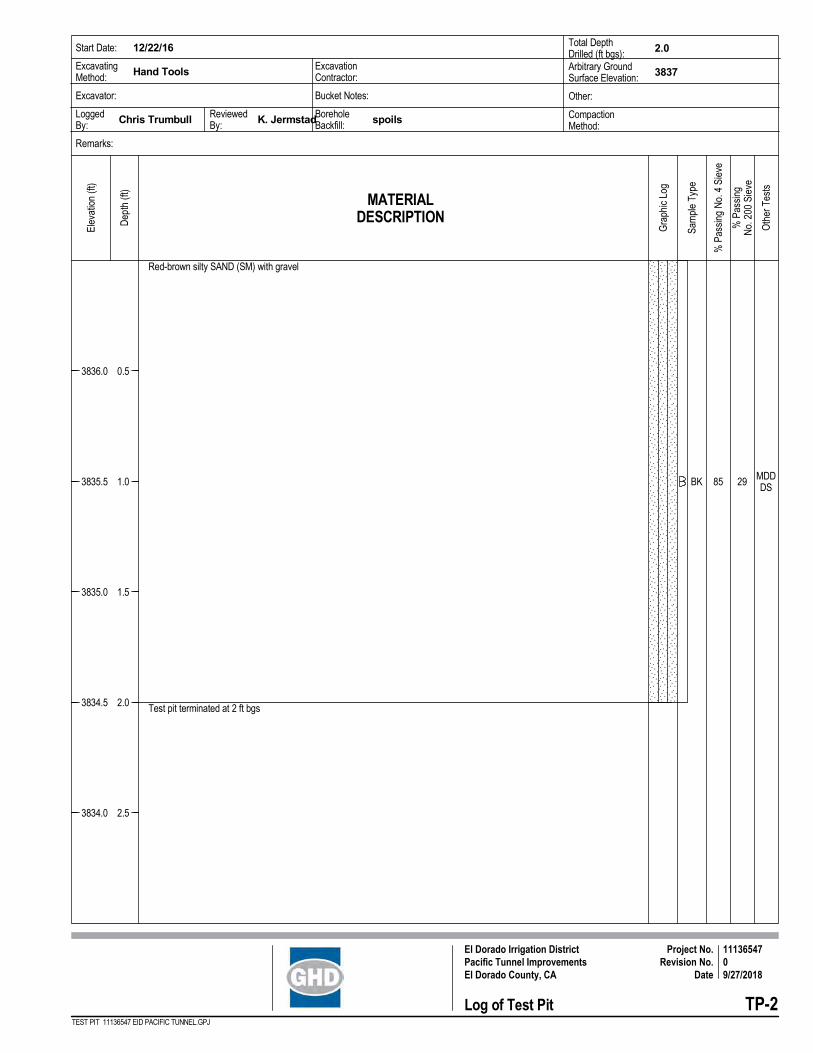
MDDDS29BK 85
Red-brown silty SAND (SM) with gravel
Test pit terminated at 2 ft bgs
ExcavatingMethod: Hand Tools
Start Date: 12/22/16
Excavator:
LoggedBy: Chris Trumbull
Remarks:
ReviewedBy: K. JermstadBorehole
Backfill: spoils
Bucket Notes:
ExcavationContractor:
Total DepthDrilled (ft bgs): 2.0
Arbitrary GroundSurface Elevation: 3837
Other:
CompactionMethod:
TP-2
Elev
atio
n (ft
)
Dep
th (f
t)
Log of Test Pit
Oth
er T
ests
* T _ *
Project No.Revision No.
Date
1113654709/27/2018
El Dorado Irrigation DistrictPacific Tunnel ImprovementsEl Dorado County, CA
TEST PIT 11136547 EID PACIFIC TUNNEL.GPJ
% P
assi
ngN
o. 2
00 S
ieve
Gra
phic
Log
Sam
ple
Type
% P
assi
ng N
o. 4
Sie
ve
MATERIALDESCRIPTION
3836.0
3835.5
3835.0
3834.5
3834.0
0.5
1.0
1.5
2.0
2.5
GHD | Geotechnical Investigation | 11110191 | Appendix C
Appendix C Geotechnical Laboratory Test Results

TP-1 0.0 Brown silty SAND (SM) with gravel 19 18 MDD, DS
TP-2 1.0 Red-brown silty SAND (SM) with gravel 19 29 MDD, DS
Summary of Laboratory Results
BoringID
Depth(ft) Description
WaterContent
(%)
DryDensity
(pcf)
MaximumSize(mm)
%<#200Sieve
LiquidLimit
PlasticLimit
PlasticityIndex Other Tests
C-1* T _ *
LABSUM TEST 11136547 EID PACIFIC TUNNEL.GPJ
El Dorado Irrigation DistrictPacific Tunnel ImprovementsEl Dorado County, CA
Project No.Revision No.
Date
1113654702/6/2017
0
5
10
15
20
25
30
35
40
45
50
55
60
65
70
75
80
85
90
95
100
0.0010.010.1110100
HYDROMETERU.S. SIEVE OPENING IN INCHES U.S. SIEVE NUMBERS
SILT OR CLAY
Classification
60
PER
CEN
T FI
NER
BY
WEI
GH
T
6 16 20 30 40 501.5 2006 8 10 1441 3/43 24
GRAIN SIZE IN MILLIMETERS
1/2 3/8 3 100 140
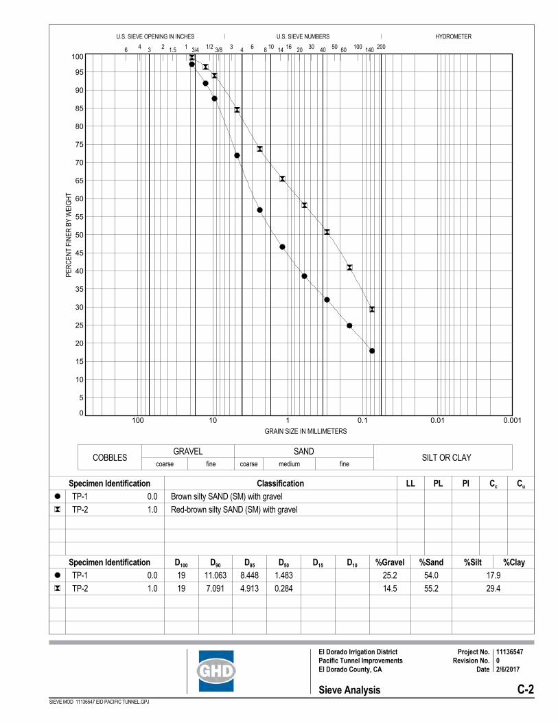
54.0
55.2
0.0
1.0
Brown silty SAND (SM) with gravel
Red-brown silty SAND (SM) with gravel
%Silt%Sand%Gravel
Specimen Identification LL
17.9
29.4
PI
11.063
7.091
8.448
4.913
D50 D15 %Clay
0.0
1.0
25.2
14.5
Specimen Identification
PL
fine
Cu
19
19
1.483
0.284
coarse fine coarse medium
Cc
TP-1
TP-2
TP-1
TP-2
COBBLESGRAVEL SAND
D100 D10D90 D85
Sieve Analysis C-2* T _ *
El Dorado Irrigation DistrictPacific Tunnel ImprovementsEl Dorado County, CA
Project No.Revision No.
Date
1113654702/6/2017
SIEVE MOD 11136547 EID PACIFIC TUNNEL.GPJ
50
55
60
65
70
75
80
85
90
95
100
10 15 20 25 30 35 40 45
DR
Y D
ENSI
TY, p
cf
WATER CONTENT, %
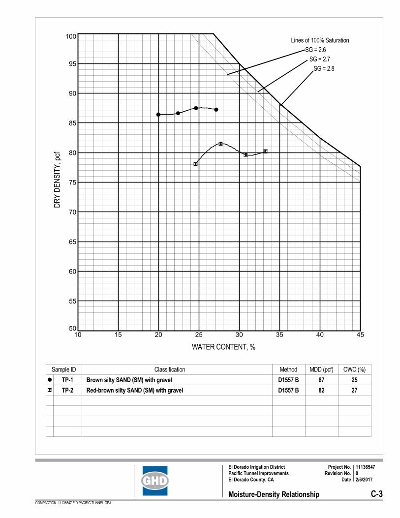
Brown silty SAND (SM) with gravel
Red-brown silty SAND (SM) with gravel
Sample ID Classification Method MDD (pcf) OWC (%)
87
82
25
27
D1557 B
D1557 B
TP-1
TP-2
Moisture-Density Relationship C-3* T _ *
El Dorado Irrigation DistrictPacific Tunnel ImprovementsEl Dorado County, CA
Project No.Revision No.
Date
1113654702/6/2017
COMPACTION 11136547 EID PACIFIC TUNNEL.GPJ
Lines of 100% Saturation
SG = 2.6
SG = 2.7
SG = 2.8

Tested By: AST
Client: GHD
Project: EID Pacific Tunnel Portal
Location: TP-1
Sample Number: TP-1 Depth: 0-1'
Proj. No.: 11136547 Date Sampled:
Sample Type: Remolded 1" by 2.49" ring.
Description:
Assumed Specific Gravity= 2.55Remarks: Strain rate in/min: .00125
Appendix
Sample No.
Water Content, %Dry Density, pcfSaturation, %Void RatioDiameter, in.Height, in.Water Content, %Dry Density, pcfSaturation, %Void RatioDiameter, in.Height, in.
Normal Stress, tsfFail. Stress, tsf Strain, %Ult. Stress, tsf Strain, %Strain rate, in./min.
Initi
alA
t Tes
t
She
ar S
tress
, tsf
0
0.25
0.5
0.75
1
1.25
1.5
Strain, %
0 5 10 15 20
1
2
3
Fail.
Stre
ss, t
sf
0
0.5
1
1.5
Normal Stress, tsf
0 0.5 1 1.5 2 2.5 3
C, tsf , deg Tan()
Results0.084
41.70.89
1
30.4
72.564.9
1.19482.49
1.0042.9
73.493.6
1.16852.490.99
0.2500.319
2.8
0.00
2
30.4
72.464.7
1.19852.49
1.0042.9
75.097.4
1.12372.490.97
0.5000.510
4.4
0.00
3
30.4
72.064.1
1.20952.49
1.0044.2
76.8105.1
1.07252.490.94
1.0000.982
3.6
0.00
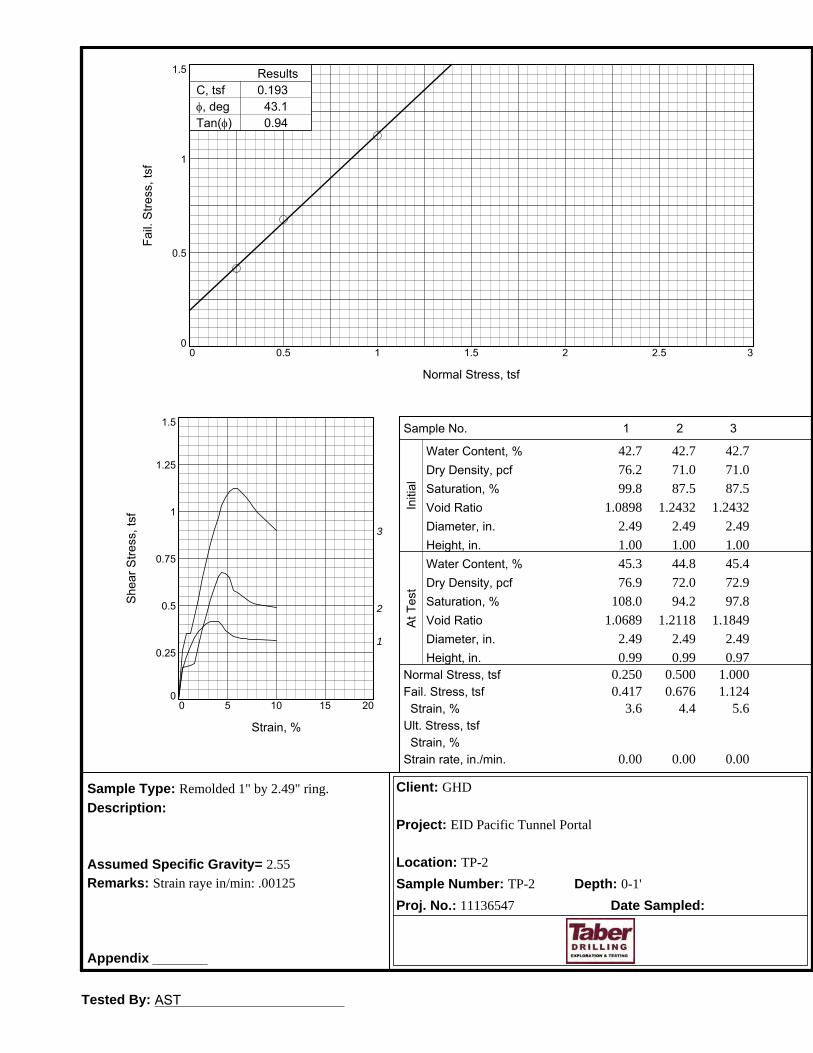
Tested By: AST
Client: GHD
Project: EID Pacific Tunnel Portal
Location: TP-2
Sample Number: TP-2 Depth: 0-1'
Proj. No.: 11136547 Date Sampled:
Sample Type: Remolded 1" by 2.49" ring.
Description:
Assumed Specific Gravity= 2.55Remarks: Strain raye in/min: .00125
Appendix
Sample No.
Water Content, %Dry Density, pcfSaturation, %Void RatioDiameter, in.Height, in.Water Content, %Dry Density, pcfSaturation, %Void RatioDiameter, in.Height, in.
Normal Stress, tsfFail. Stress, tsf Strain, %Ult. Stress, tsf Strain, %Strain rate, in./min.
Initi
alA
t Tes
t
She
ar S
tress
, tsf
0
0.25
0.5
0.75
1
1.25
1.5
Strain, %
0 5 10 15 20
1
2
3
Fail.
Stre
ss, t
sf
0
0.5
1
1.5
Normal Stress, tsf
0 0.5 1 1.5 2 2.5 3
C, tsf , deg Tan()
Results0.193
43.10.94
1
42.7
76.299.8
1.08982.49
1.0045.3
76.9108.0
1.06892.490.99
0.2500.417
3.6
0.00
2
42.7
71.087.5
1.24322.49
1.0044.8
72.094.2
1.21182.490.99
0.5000.676
4.4
0.00
3
42.7
71.087.5
1.24322.49
1.0045.4
72.997.8
1.18492.490.97
1.0001.124
5.6
0.00
GHD | Geotechnical Investigation | 11110191 | Appendix E
Appendix D Seismic Refraction Survey Results
Page 1 of 7
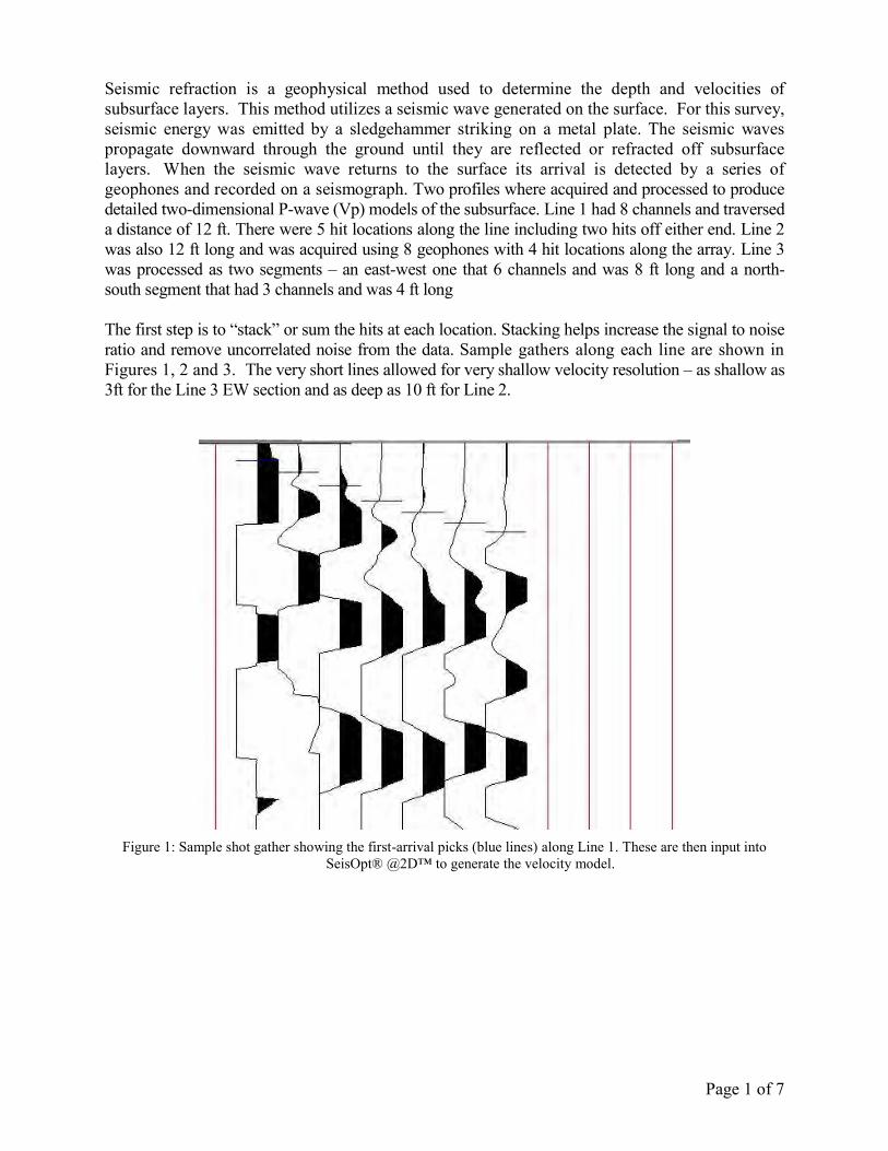
Seismic refraction is a geophysical method used to determine the depth and velocities of subsurface layers. This method utilizes a seismic wave generated on the surface. For this survey, seismic energy was emitted by a sledgehammer striking on a metal plate. The seismic waves propagate downward through the ground until they are reflected or refracted off subsurface layers. When the seismic wave returns to the surface its arrival is detected by a series of geophones and recorded on a seismograph. Two profiles where acquired and processed to produce detailed two-dimensional P-wave (Vp) models of the subsurface. Line 1 had 8 channels and traversed a distance of 12 ft. There were 5 hit locations along the line including two hits off either end. Line 2 was also 12 ft long and was acquired using 8 geophones with 4 hit locations along the array. Line 3 was processed as two segments – an east-west one that 6 channels and was 8 ft long and a north-south segment that had 3 channels and was 4 ft long The first step is to “stack” or sum the hits at each location. Stacking helps increase the signal to noise ratio and remove uncorrelated noise from the data. Sample gathers along each line are shown in Figures 1, 2 and 3. The very short lines allowed for very shallow velocity resolution – as shallow as 3ft for the Line 3 EW section and as deep as 10 ft for Line 2.
Figure 1: Sample shot gather showing the first-arrival picks (blue lines) along Line 1. These are then input into
SeisOpt® @2D™ to generate the velocity model.
Page 2 of 7
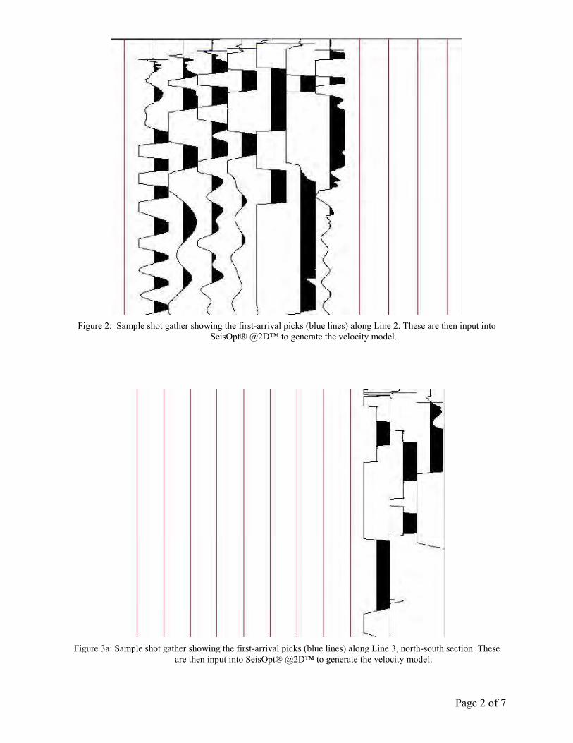
Figure 2: Sample shot gather showing the first-arrival picks (blue lines) along Line 2. These are then input into
SeisOpt® @2D™ to generate the velocity model.
Figure 3a: Sample shot gather showing the first-arrival picks (blue lines) along Line 3, north-south section. These
are then input into SeisOpt® @2D™ to generate the velocity model.
Page 3 of 7
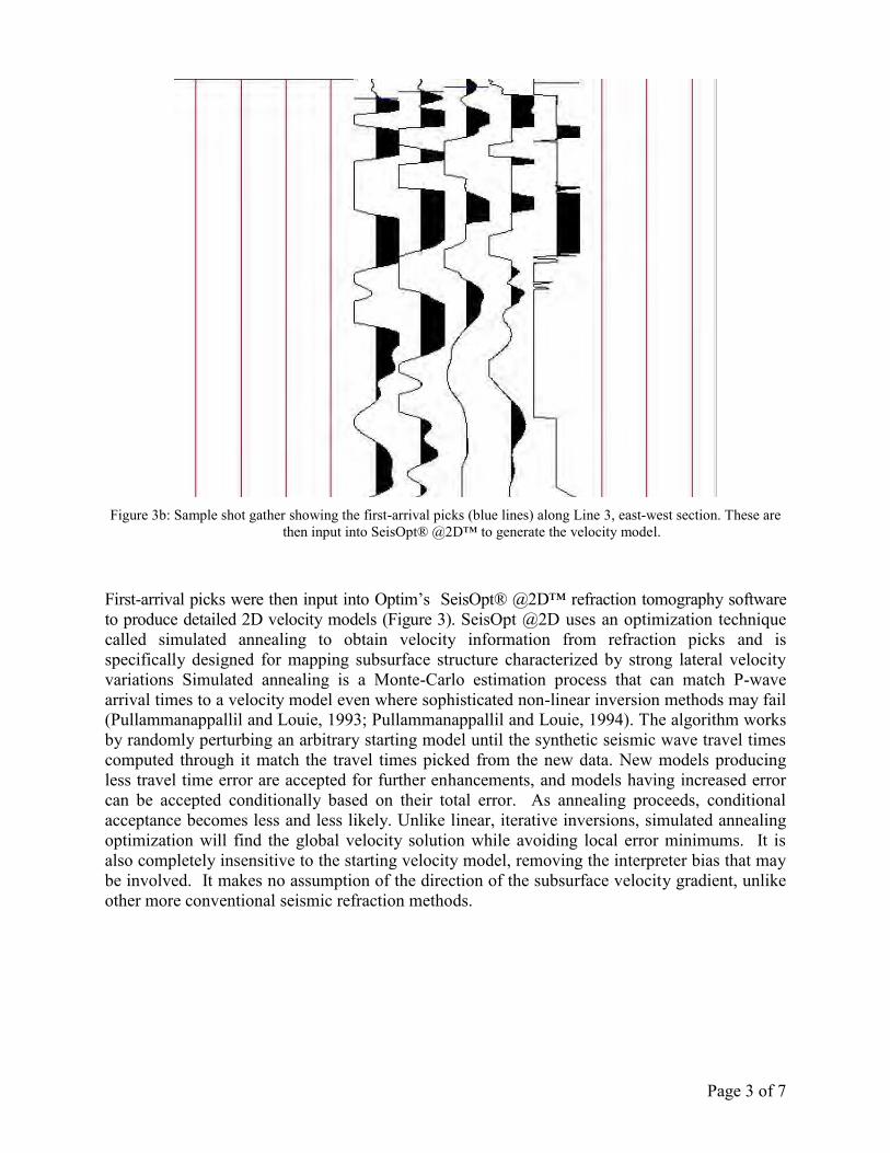
Figure 3b: Sample shot gather showing the first-arrival picks (blue lines) along Line 3, east-west section. These are
then input into SeisOpt® @2D™ to generate the velocity model.
First-arrival picks were then input into Optim’s SeisOpt® @2D™ refraction tomography software to produce detailed 2D velocity models (Figure 3). SeisOpt @2D uses an optimization technique called simulated annealing to obtain velocity information from refraction picks and is specifically designed for mapping subsurface structure characterized by strong lateral velocity variations Simulated annealing is a Monte-Carlo estimation process that can match P-wave arrival times to a velocity model even where sophisticated non-linear inversion methods may fail (Pullammanappallil and Louie, 1993; Pullammanappallil and Louie, 1994). The algorithm works by randomly perturbing an arbitrary starting model until the synthetic seismic wave travel times computed through it match the travel times picked from the new data. New models producing less travel time error are accepted for further enhancements, and models having increased error can be accepted conditionally based on their total error. As annealing proceeds, conditional acceptance becomes less and less likely. Unlike linear, iterative inversions, simulated annealing optimization will find the global velocity solution while avoiding local error minimums. It is also completely insensitive to the starting velocity model, removing the interpreter bias that may be involved. It makes no assumption of the direction of the subsurface velocity gradient, unlike other more conventional seismic refraction methods.
Page 4 of 7
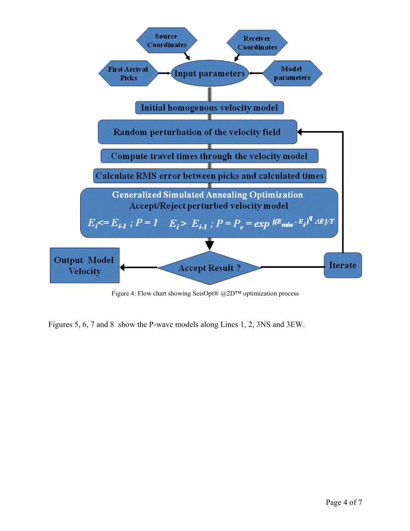
Figure 4: Flow chart showing SeisOpt® @2D™ optimization process
Figures 5, 6, 7 and 8 show the P-wave models along Lines 1, 2, 3NS and 3EW.
Page 5 of 7
-1 0 1 2 3 4 5 6 7 8 9 10 11 12
Distance, ft
-1 0 1 2 3 4 5 6 7 8 9 10 11 12
3826
3827
3828
3829
3830
3831
3832
Ele
vatio
n,
ft
3826
3827
3828
3829
3830
3831
3832
200
400
600
800
100
0
120
0
140
0
160
0
180
0
200
0
220
0
240
0
260
0
280
0
300
0
320
0
340
0
360
0
380
0
400
0
420
0
440
0
460
0
480
0
500
0
P-wave Velocity, ft/s
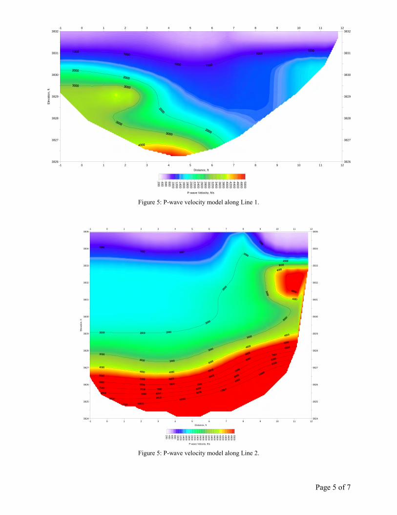
Figure 5: P-wave velocity model along Line 1.
-1 0 1 2 3 4 5 6 7 8 9 10 11 12
Distance, ft
-1 0 1 2 3 4 5 6 7 8 9 10 11 12
3824
3825
3826
3827
3828
3829
3830
3831
3832
3833
3834
3835
Ele
va
tio
n,
ft
3824
3825
3826
3827
3828
3829
3830
3831
3832
3833
3834
38352
00
40
0
60
0
80
0
10
00
12
00
14
00
16
00
18
00
20
00
22
00
24
00
26
00
28
00
30
00
32
00
34
00
36
00
38
00
40
00
42
00
44
00
46
00
48
00
50
00
P-wave Velocity, ft/s
Figure 5: P-wave velocity model along Line 2.
Page 6 of 7
0 1 2 3 4 5 6 7 8
Distance, ft
0 1 2 3 4 5 6 7 8
3830
3831
3832
3833
3834
3835
3836
3837
Ele
va
tio
n,
ft
3830
3831
3832
3833
3834
3835
3836
3837
20
0
40
0
60
0
80
0
10
00
12
00
14
00
16
00
18
00
20
00
22
00
24
00
26
00
28
00
30
00
32
00
34
00
36
00
38
00
40
00
42
00
44
00
46
00
48
00
50
00
P-wave Velocity, ft/s
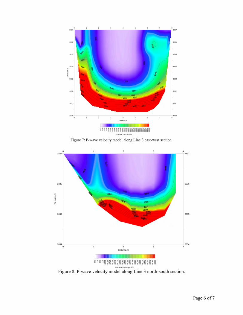
Figure 7: P-wave velocity model along Line 3 east-west section.
0 1 2 3 4
Distance, ft
0 1 2 3 4
3834
3835
3836
3837
Ele
va
tio
n,
ft
3834
3835
3836
3837
200
400
600
800
1000
1200
1400
1600
1800
2000
2200
2400
2600
2800
3000
3200
3400
3600
3800
4000
4200
4400
4600
4800
5000
P-wave Velocity, ft/s
Figure 8: P-wave velocity model along Line 3 north-south section.

Page 7 of 7
References:
Pullammanappallil, S.K., and Louie, J.N., 1993, Inversion of seismic reflection traveltimes using a nonlinear optimization scheme: Geophysics, v. 58, p. 1607-1620.
Pullammanappallil, S.K., and Louie, J.N., 1994, A generalized simulated-annealing optimization for inversion of first arrival times: Bulletin of the Seismological Society of America, v. 84, p. 1397-1409.
GHD | Geotechnical Investigation | 11110191 | Appendix E
Appendix E Tunnel Condition Assessment
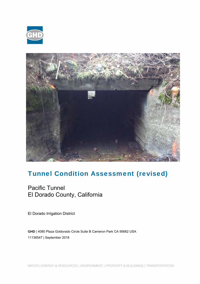
Tunnel Condition Assessment (revised) Pacific Tunnel El Dorado County, California
El Dorado Irrigation District
GHD | 4080 Plaza Goldorado Circle Suite B Cameron Park CA 95682 USA
11136547 | September 2018

Executive Summary
The Pacific Tunnel is an approximately 190-foot-long untreated water tunnel in El Dorado Irrigation District’s water delivery system. The Pacific Tunnel conveys flow along the El Dorado Canal (FERC Project 184) below access road R82.
The approximate 180-foot horseshoe-shaped tunnel (nominal) is unlined rock over much of its length with timber-lined sections at the inlet and outlet portals.
El Dorado Irrigation District (District) scheduled an annual maintenance outage in October 2016 to inspect the Pacific Tunnel and to construct improvements. The tunnel inspection occurred on December 22, 2016. Overall, the condition of the portals and tunnel is good.
Tunnel inspection photographs are provided in Attachment A.
If you have any questions regarding the information contained in this report, or if we may be of further assistance, please do not hesitate to contact us.
Sincerely,
GHD
David B. Jermstad, P.G., C.E.G.
Senior Engineer
GHD | Tunnel Condition Assessment | 11136547 | Page iii
Table of Contents
1. Introduction 5
2. Tunnel Inspection Overview 5
3. Tunnel Inspection Safety 5
3.1 Identified Hazards and Mitigation Measures 5
3.1.1 Tunnel Instability 5 3.1.2 Atmospheric Hazards 5 3.1.3 Operational Hazards 5 3.1.4 Biologic Hazards 6
3.2 Applicable Safety Regulations 6
3.3 Safety Preparations 6
3.3.1 Communication 6 3.3.2 Personal Protective Equipment 6 3.3.3 Safety Instruction 7 3.3.3.1 Overview 7 3.3.3.2 Safety Instruction 7 3.3.3.3 Biologic 7 3.3.3.4 Confined Space 7 3.3.4 Pre-entry Activities and Monitoring During Inspection 8
4. Inspection Methodology 8
5. Observations and Recommendations 8
5.1 Observations 8
5.2 Recommendations 11
6. Summary 11
7. Limitations 11
Table Index
Table 4.1 Summary of Observations 8
Table 5.1 Summary of Recommendations 11
Attachment Index Attachment A Photographs
GHD | Tunnel Condition Assessment | 11136547 | Page iv
Distribution
To: El Dorado Irrigation District
Brian Mueller, P.E.
2890 Mosquito Road
Placerville, CA 95667
cc: Dan Gibson
From: GHD
David Jermstad, PG, CEG
4080 Plaza Goldorado Circle, Suite B
Cameron Park, CA 95682

GHD | Tunnel Condition Assessment | 11136547 | Page 5
1. Introduction
This report presents the findings, conclusions, and recommendations developed from our geotechnical engineering investigation. The investigation was conducted in accordance with the Professional Service Agreement *On-Call Contract – Geotechnical Notice to Proceed N1216-291 dated 12/05/16. This report supersedes our previous geotechnical investigation report dated February 6, 2017.
2. Tunnel Inspection Overview
The Pacific Tunnel was inspected on December 22, 2016. The inspection team entered the tunnel at the upstream gate access, inspected the intake portal, walked downstream to approximately Station 1+78 and exited at the downstream portal access.
3. Tunnel Inspection Safety
3.1 Identified Hazards and Mitigation Measures
Safety was a high priority for the tunnel inspection. Three primary hazards, which are common to all tunnel inspections, were identified: tunnel instability, atmospheric hazards immediately dangerous to life or health (IDLH), and operational hazards. Steps were taken to mitigate the risks associated with each of these hazards.
3.1.1 Tunnel Instability
GHD’s trained inspectors watched for localized tunnel instability throughout the inspection. The absence of hydraulic anomalies in the tunnel suggested that the tunnel cross section was stable and that no immediate need for scaling was observed.
3.1.2 Atmospheric Hazards
Recent work in the Pacific Tunnel did not identify atmospheric hazards, but unsafe oxygen and hydrogen sulfide levels were the most likely atmospheric hazards. Throughout the inspection, the atmosphere was monitored for unsafe levels of oxygen and hydrogen sulfide. At no point during the inspection did air monitors indicate a potentially hazardous atmosphere.
3.1.3 Operational Hazards
The most significant operational hazard on the Pacific Tunnel inspection was the potential for flooding. Flooding was prevented through a lock-out-tag-out (LOTO) protocol that isolated the Pacific Tunnel from the rest of the system. Two forms of LOTO exist in most agencies: physical and administrative. Administrative LOTO places a clearance tag or man-on-line tag (typically paper) on equipment control surfaces. Operators are trained not to place equipment in service if a tag is present. Physical LOTO requires that equipment be temporarily disabled or prevented from
GHD | Tunnel Condition Assessment | 11136547 | Page 6
operating. A combination of administrative and physical LOTO methods was used during the Pacific Tunnel outage.
The LOTO actions were effective and provided a safe work environment for the inspection.
3.1.4 Biologic Hazards
The tunnel back above normal flow line was colonized by spiders.
3.2 Applicable Safety Regulations
There are no specific tunnel safety regulations covering the inspection of in-service water tunnels in California. A combination of the General Industry Safety Orders and Tunnel Safety Orders was applied to the inspection.
3.3 Safety Preparations
3.3.1 Communication
Communication between the surface support team and tunnel entrants is difficult in tunnel inspections. The team checked in and out with District personnel during the inspection. The team included two attendants at the tunnel adit that could be sent for help if needed. Fortunately, emergency communication was not necessary.
3.3.2 Personal Protective Equipment
Personal protective equipment for the tunnel entrants was selected to protect against the identified hazards, including:
GHD | Tunnel Condition Assessment | 11136547 | Page 7
Hard hat
Helmet mounted light
Flashlight and spare batteries
Back-up flashlights
Safety glasses
Atmospheric monitoring meters – one per inspection team
Gloves
Thermal shirt
Water repellant jacket
Walking sticks
Waders and sturdy boots
Emergency whistle
First aid kit—one per inspection team (safety rep)
Water and snacks
3.3.3 Safety Instruction
On the morning of December 22, 2016 the tunnel entrants and support team participated in an extended safety tailboard. The agenda included the topics discussed below.
3.3.3.1 Overview
Purpose of inspection, access, anticipated conditions, safety procedures, and emergency procedures.
3.3.3.2 Safety Instruction
Recognition and avoidance of hazards, awareness of other work going on at/near the Pacific Tunnel, air monitoring, illumination, communication, flooding, LOTO, use of personal protective equipment, fire prevention and control, emergency procedures, evacuation, and personal accountability requirements.
3.3.3.3 Biologic
Recognition and avoidance of spiders.
3.3.3.4 Confined Space
Recognition and protective measures for confined space entry.
GHD | Tunnel Condition Assessment | 11136547 | Page 8
3.3.4 Pre-entry Activities and Monitoring During Inspection
Prior to entry, the entry permit was updated with information from the hazards assessment, incident action plan, communication plan, LOTO procedures, personnel accountability plan, personal protective equipment list, and atmospheric monitoring equipment list.
On the surface, the standby rescue team monitored surface conditions.
4. Inspection Methodology
The objective of the inspection was to visually inspect and evaluate the current condition of Pacific Tunnel. To achieve this objective, the inspection party performed the condition assessment, including geologic interpretation of the tunnel condition, identification of anomalies, measurement of cross-sectional dimensions, measurement of seeps and water inflow, and photography of conditions.
5. Observations and Recommendations
5.1 Observations
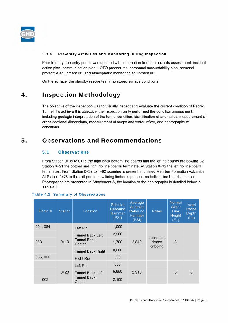
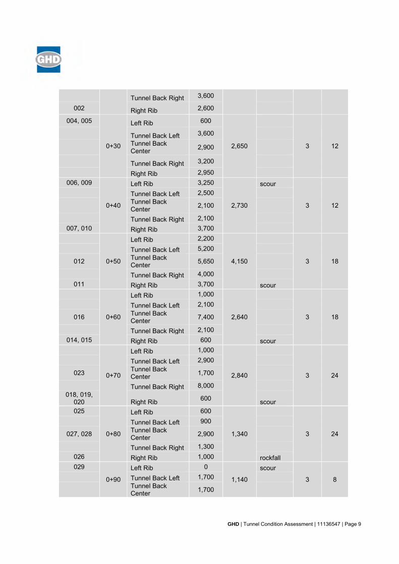
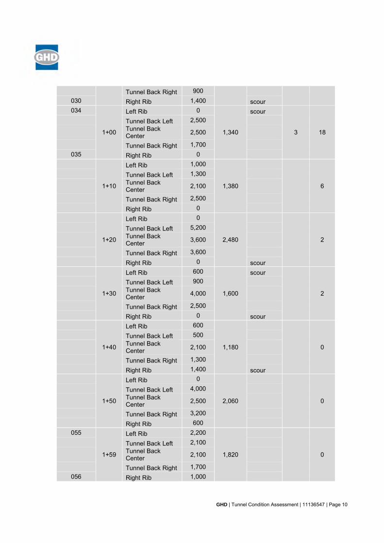
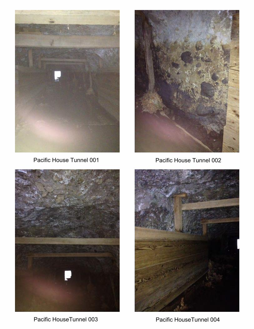
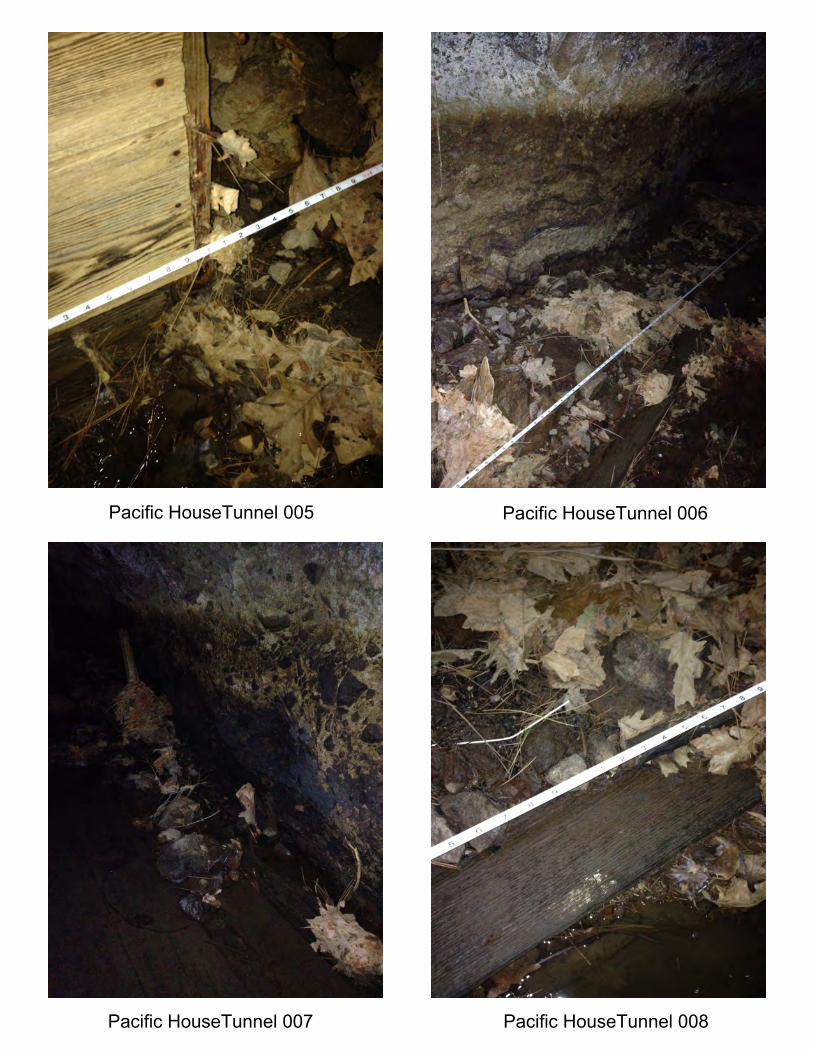
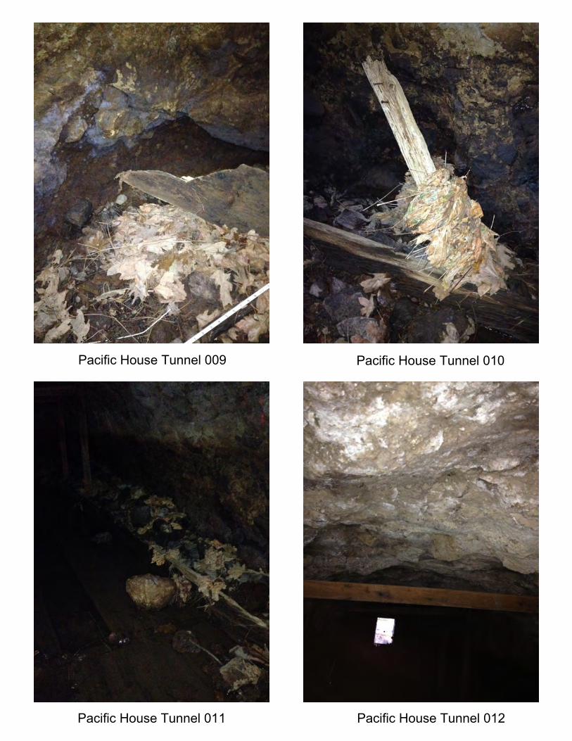
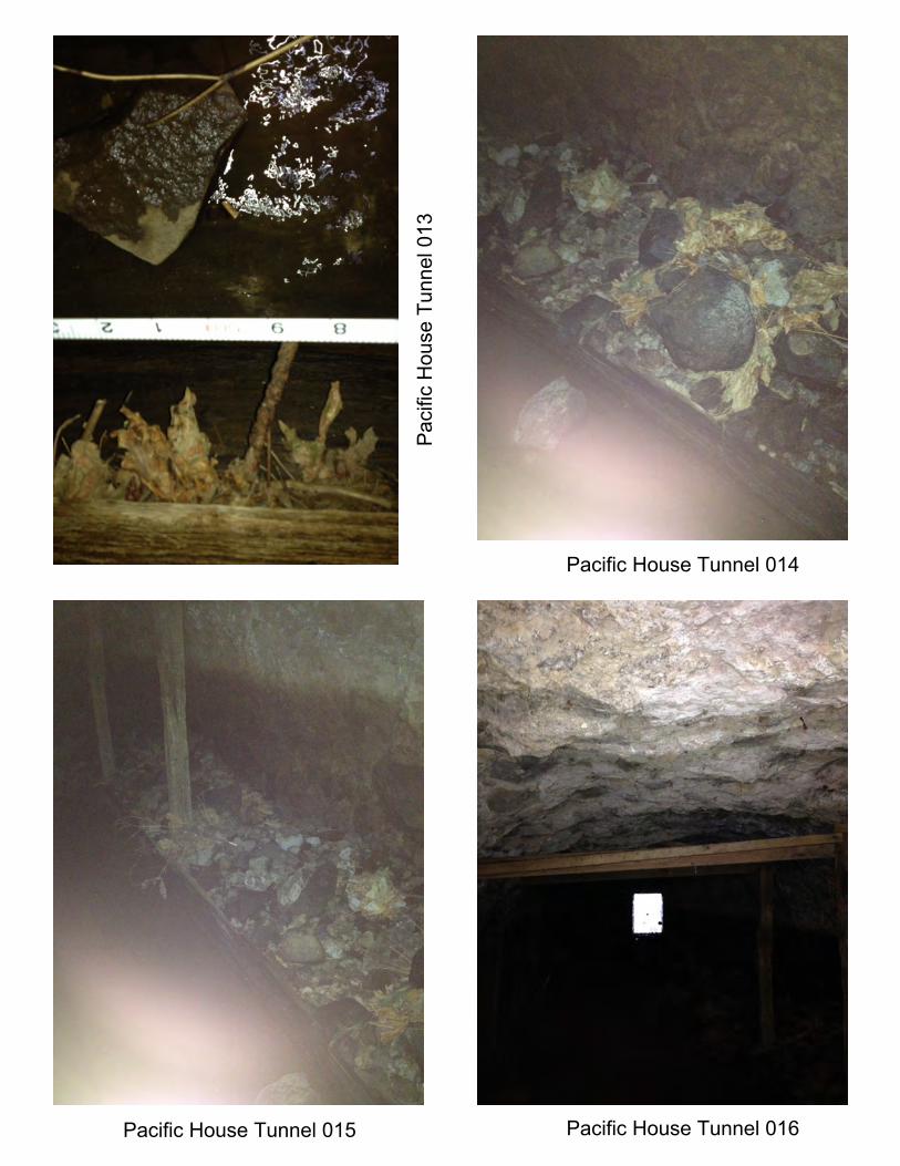
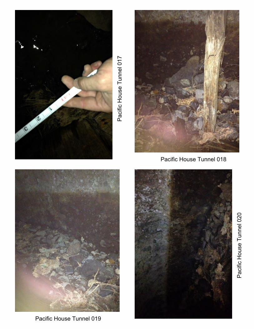
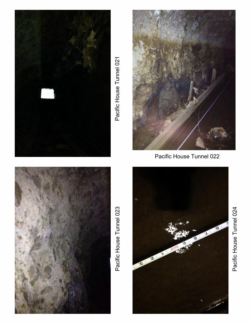
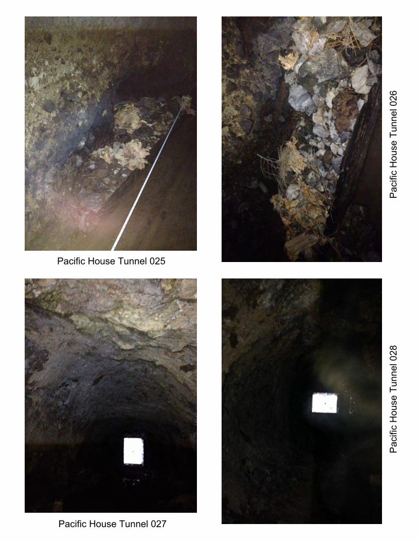
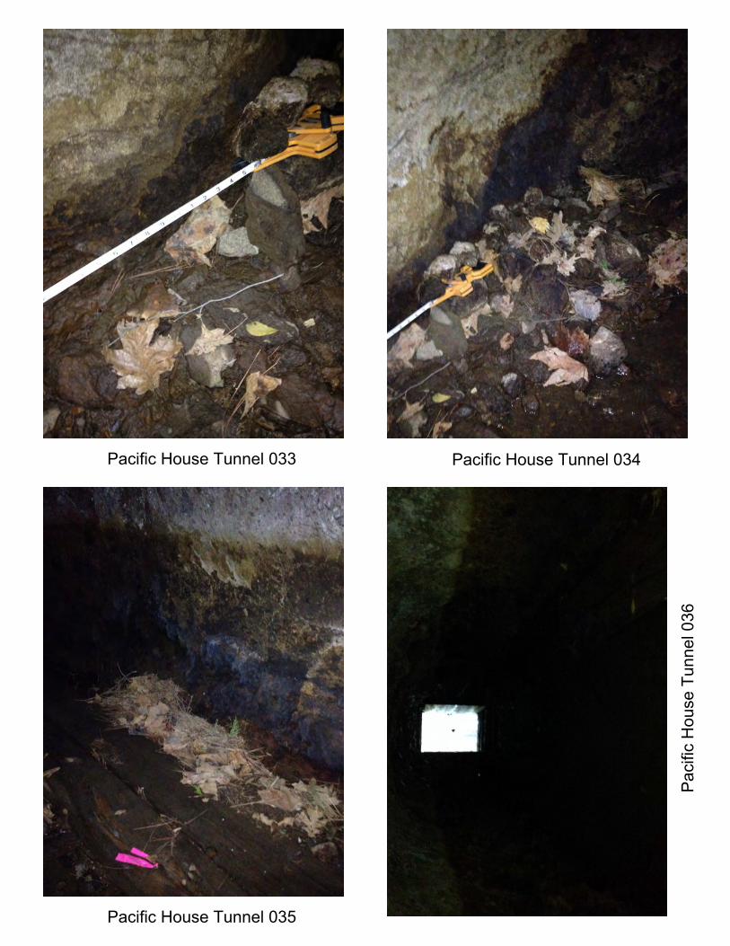
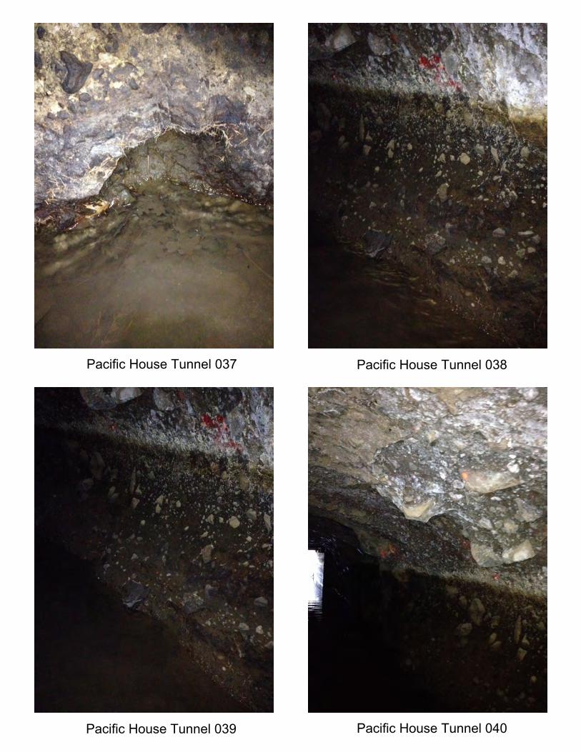
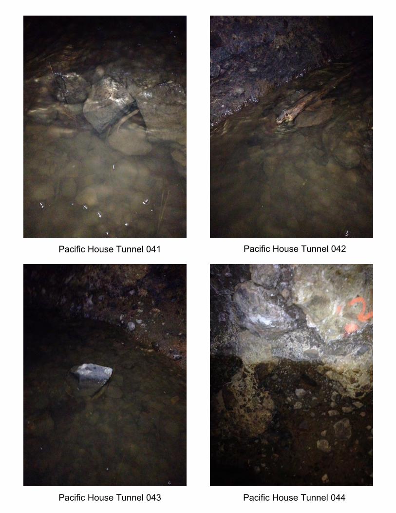
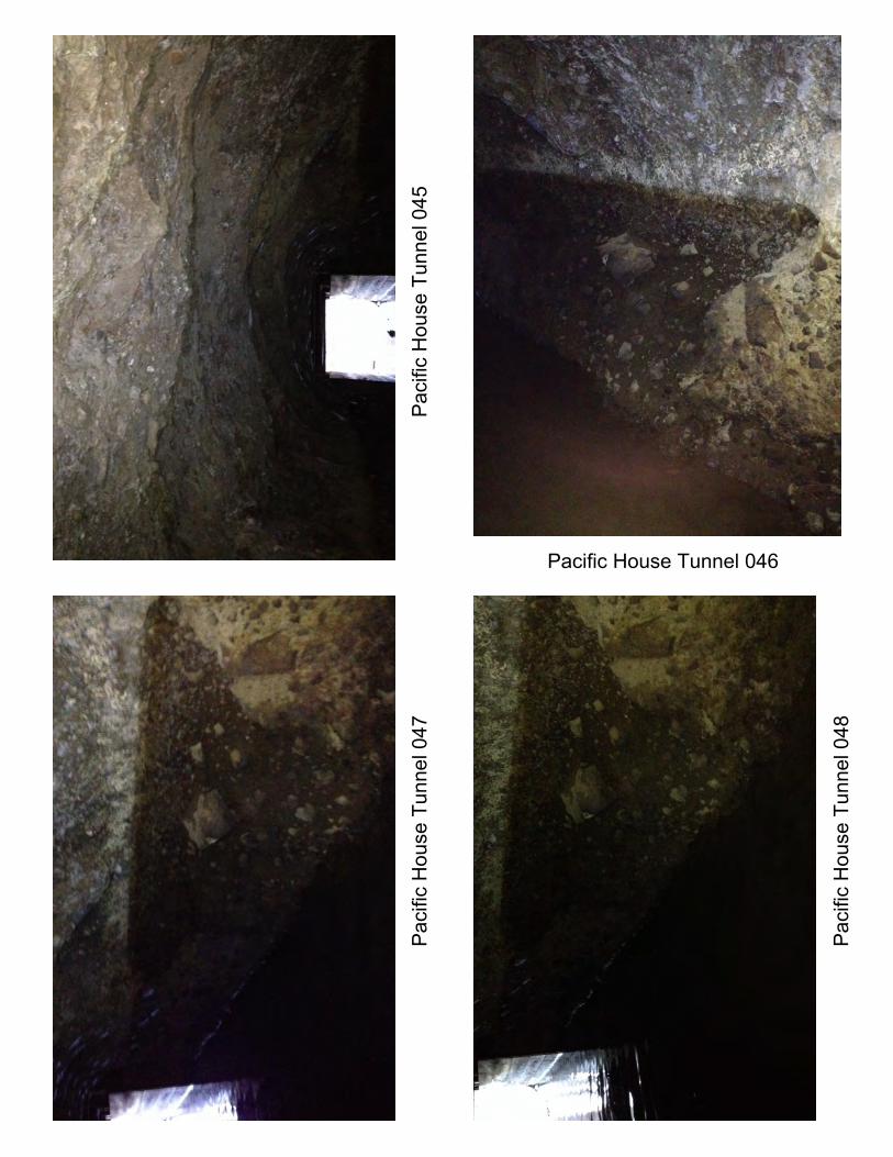
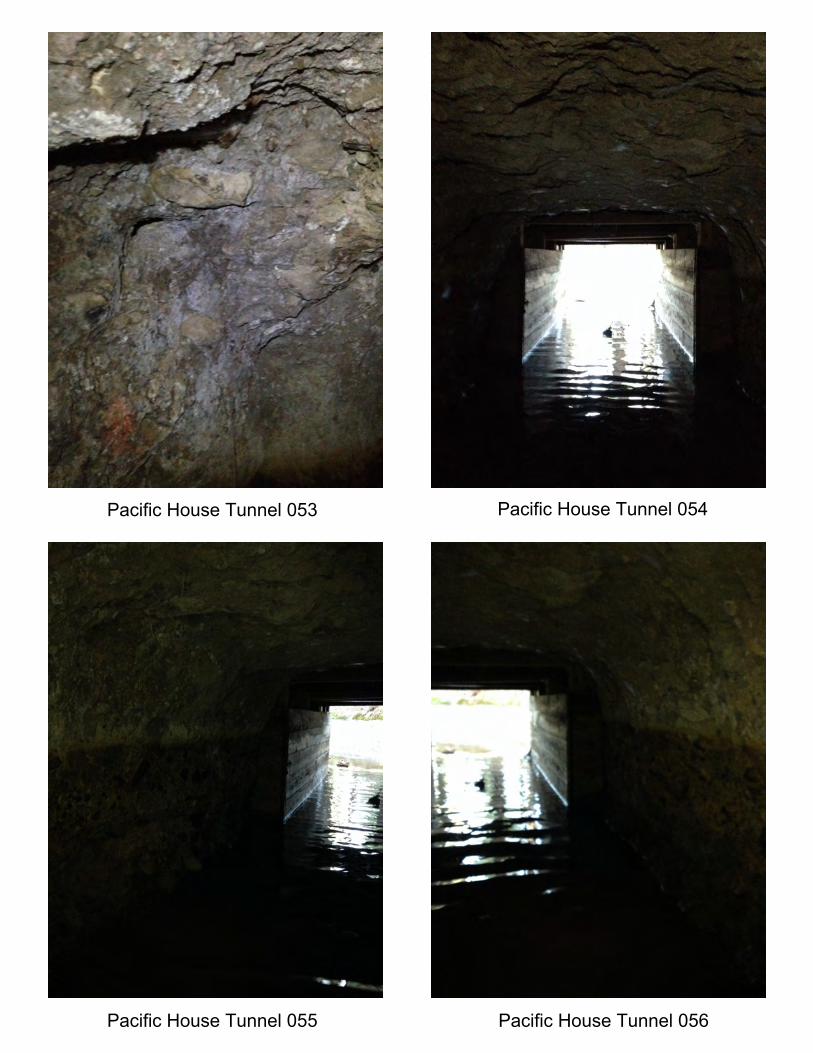
From Station 0+05 to 0+15 the right back bottom line boards and the left rib boards are bowing. At Station 0+21 the bottom and right rib line boards terminate. At Station 0+32 the left rib line board terminates. From Station 0+32 to 1+62 scouring is present in unlined Mehrten Formation volcanics. At Station 1+78 to the exit portal, new lining timber is present, no bottom line boards installed. Photographs are presented in Attachment A, the location of the photographs is detailed below in Table 4.1.
Table 4.1 Summary of Observations
Photo # Station Location
Schmidt Rebound Hammer
(PSI)
Average Schmidt Rebound Hammer
(PSI)
Notes
Normal Water Line
Height (Ft.)
Invert Probe Depth (In.)
001, 064
0+10
Left Rib 1,000
2,840 distressed
timber cribbing
3
Tunnel Back Left 2,900
063 Tunnel Back Center 1,700
Tunnel Back Right 8,000
065, 066 Right Rib 600
0+20
Left Rib 600
2,910
3 6 Tunnel Back Left 5,650
003 Tunnel Back Center 2,100
GHD | Tunnel Condition Assessment | 11136547 | Page 9
Tunnel Back Right 3,600 002 Right Rib 2,600
004, 005
0+30
Left Rib 600
2,650
3 12
Tunnel Back Left 3,600
Tunnel Back Center 2,900
Tunnel Back Right 3,200 Right Rib 2,950
006, 009
0+40
Left Rib 3,250
2,730
scour
3 12
Tunnel Back Left 2,500
Tunnel Back Center 2,100
Tunnel Back Right 2,100 007, 010 Right Rib 3,700
0+50
Left Rib 2,200
4,150
3 18
Tunnel Back Left 5,200
012 Tunnel Back Center 5,650
Tunnel Back Right 4,000 011 Right Rib 3,700 scour
0+60
Left Rib 1,000
2,640
3 18
Tunnel Back Left 2,100
016 Tunnel Back Center 7,400
Tunnel Back Right 2,100 014, 015 Right Rib 600 scour
0+70
Left Rib 1,000
2,840
3 24
Tunnel Back Left 2,900
023 Tunnel Back Center 1,700
Tunnel Back Right 8,000 018, 019,
020 Right Rib 600 scour 025
0+80
Left Rib 600
1,340
3 24
Tunnel Back Left 900
027, 028 Tunnel Back Center 2,900
Tunnel Back Right 1,300 026 Right Rib 1,000 rockfall 029
0+90
Left Rib 0
1,140
scour
3 8 Tunnel Back Left 1,700
Tunnel Back Center 1,700
GHD | Tunnel Condition Assessment | 11136547 | Page 10
Tunnel Back Right 900 030 Right Rib 1,400 scour 034
1+00
Left Rib 0
1,340
scour
3 18
Tunnel Back Left 2,500
Tunnel Back Center 2,500
Tunnel Back Right 1,700 035 Right Rib 0
1+10
Left Rib 1,000
1,380
6
Tunnel Back Left 1,300
Tunnel Back Center 2,100
Tunnel Back Right 2,500 Right Rib 0
1+20
Left Rib 0
2,480
2
Tunnel Back Left 5,200
Tunnel Back Center 3,600
Tunnel Back Right 3,600 Right Rib 0 scour
1+30
Left Rib 600
1,600
scour
2
Tunnel Back Left 900
Tunnel Back Center 4,000
Tunnel Back Right 2,500 Right Rib 0 scour
1+40
Left Rib 600
1,180
0
Tunnel Back Left 500
Tunnel Back Center 2,100
Tunnel Back Right 1,300 Right Rib 1,400 scour
1+50
Left Rib 0
2,060
0
Tunnel Back Left 4,000
Tunnel Back Center 2,500
Tunnel Back Right 3,200 Right Rib 600
055
1+59
Left Rib 2,200
1,820
0
Tunnel Back Left 2,100
Tunnel Back Center 2,100
Tunnel Back Right 1,700 056 Right Rib 1,000
GHD | Tunnel Condition Assessment | 11136547 | Page 11
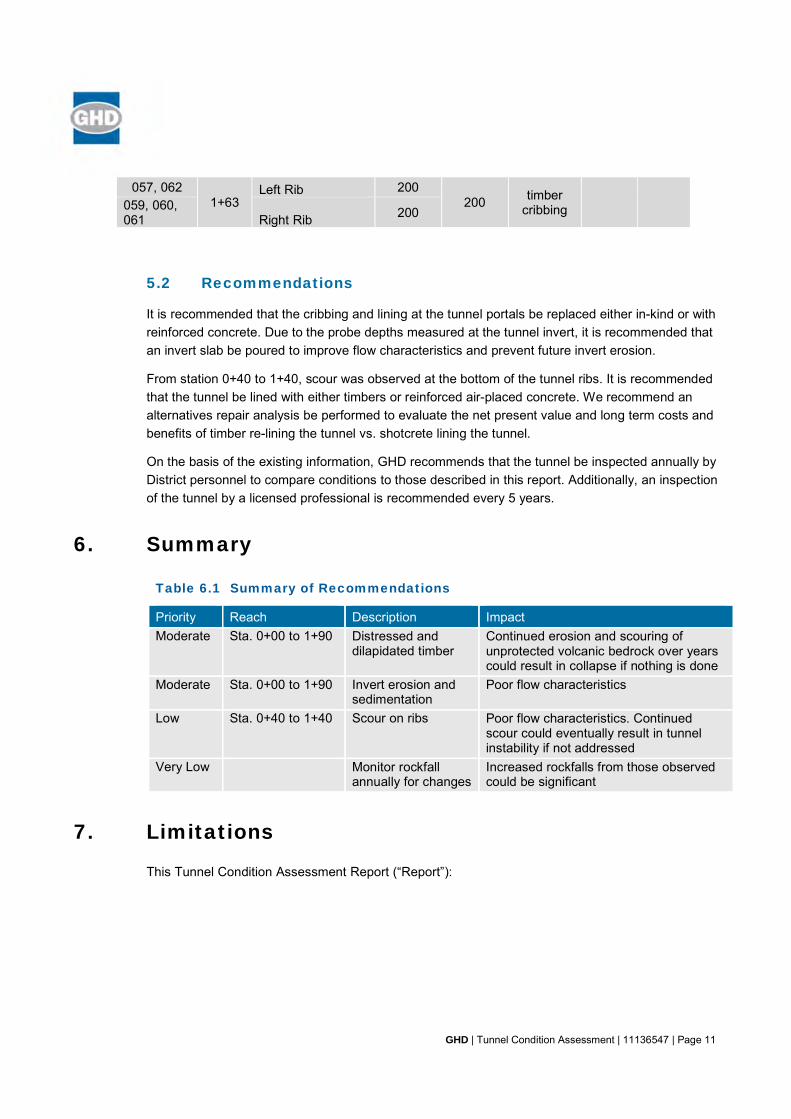
057, 062 1+63
Left Rib 200 200 timber
cribbing 059, 060, 061 Right Rib 200
5.2 Recommendations
It is recommended that the cribbing and lining at the tunnel portals be replaced either in-kind or with reinforced concrete. Due to the probe depths measured at the tunnel invert, it is recommended that an invert slab be poured to improve flow characteristics and prevent future invert erosion.
From station 0+40 to 1+40, scour was observed at the bottom of the tunnel ribs. It is recommended that the tunnel be lined with either timbers or reinforced air-placed concrete. We recommend an alternatives repair analysis be performed to evaluate the net present value and long term costs and benefits of timber re-lining the tunnel vs. shotcrete lining the tunnel.
On the basis of the existing information, GHD recommends that the tunnel be inspected annually by District personnel to compare conditions to those described in this report. Additionally, an inspection of the tunnel by a licensed professional is recommended every 5 years.
6. Summary
Table 6.1 Summary of Recommendations
Priority Reach Description Impact Moderate Sta. 0+00 to 1+90 Distressed and
dilapidated timber Continued erosion and scouring of unprotected volcanic bedrock over years could result in collapse if nothing is done
Moderate Sta. 0+00 to 1+90 Invert erosion and sedimentation
Poor flow characteristics
Low Sta. 0+40 to 1+40 Scour on ribs Poor flow characteristics. Continued scour could eventually result in tunnel instability if not addressed
Very Low Monitor rockfall annually for changes
Increased rockfalls from those observed could be significant
7. Limitations
This Tunnel Condition Assessment Report (“Report”):
GHD | Tunnel Condition Assessment | 11136547 | Page 12
Has been prepared by GHD for the El Dorado Irrigation District (EID) under the professional supervision of those senior partners and/or senior staff whose seals and signatures appear herein
May only be used and relied on by EID, which is responsible to ensure that all relevant parties to the project, including designers, contractors, subcontractors, etc., are made aware of this report in its entirety
Must not be copied to, used by, or relied on by any person other than EID without the prior written consent of GHD
May only be used for the purpose of engineering design of the proposed structures at the project site described in this report (and must not be used for any other purpose)
GHD and its servants, employees and officers otherwise expressly disclaim responsibility to any person other than EID arising from or in connection with this Report.
To the maximum extent permitted by law, all implied warranties and conditions in relation to the services provided by GHD and the Report are excluded unless they are expressly stated to apply in this Report.
The services undertaken by GHD in connection with preparing this Report:
Were limited to those specifically detailed in sections 1-5;
Did not include GHD undertaking testing at some parts of the site.
The opinions, conclusions and any recommendations in this Report are based on assumptions made by GHD when undertaking services and preparing the Report (“Assumptions”), including (but not limited to):
The condition has remained essentially unchanged since our site visit.
GHD expressly disclaims responsibility for any error in, or omission from, this Report arising from or in connection with any of the Assumptions being incorrect.
Subject to the paragraphs in this section of the Report, the opinions, conclusions and any recommendations in this Report are based on conditions encountered and information reviewed at the time of preparation and may be relied on until 1-year from the date of the report after which time, GHD expressly disclaims responsibility for any error in, or omission from, this Report arising from or in connection with those opinions, conclusions and any recommendations.
GHD | Tunnel Condition Assessment | 11136547 | Attachment A
Attachment A Photographs
Pacific House Tunnel 001 Pacific House Tunnel 002
Pacific HouseTunnel 003 Pacific HouseTunnel 004
Pacific HouseTunnel 005 Pacific HouseTunnel 006
Pacific HouseTunnel 007 Pacific HouseTunnel 008
Pacific House Tunnel 009 Pacific House Tunnel 010
Pacific House Tunnel 011 Pacific House Tunnel 012
Pac
ific
Hou
se T
unne
l 013
Pacific House Tunnel 014
Pacific House Tunnel 015 Pacific House Tunnel 016
Pac
ific
Hou
se T
unne
l 017
Pacific House Tunnel 018
Pacific House Tunnel 019
Pac
ific
Hou
se T
unne
l 020
Pac
ific
Hou
se T
unne
l 021
Pacific House Tunnel 022
Pac
ific
Hou
se T
unne
l 023
Pac
ific
Hou
se T
unne
l 024
Pacific House Tunnel 025
Pac
ific
Hou
se T
unne
l 026
Pacific House Tunnel 027
Pac
ific
Hou
se T
unne
l 028

Pacific House Tunnel 029 Pacific House Tunnel 030
Pacific House Tunnel 031 Pacific House Tunnel 032
Pacific House Tunnel 033 Pacific House Tunnel 034
Pacific House Tunnel 035
Pac
ific
Hou
se T
unne
l 036
Pacific House Tunnel 037 Pacific House Tunnel 038
Pacific House Tunnel 039 Pacific House Tunnel 040
Pacific House Tunnel 041 Pacific House Tunnel 042
Pacific House Tunnel 043 Pacific House Tunnel 044
Pac
ific
Hou
se T
unne
l 045
Pacific House Tunnel 046
Pac
ific
Hou
se T
unne
l 047
Pac
ific
Hou
se T
unne
l 048

Pacific House Tunnel 049 Pacific House Tunnel 050
Pacific House Tunnel 051 Pacific House Tunnel 052
Pacific House Tunnel 053 Pacific House Tunnel 054
Pacific House Tunnel 055 Pacific House Tunnel 056
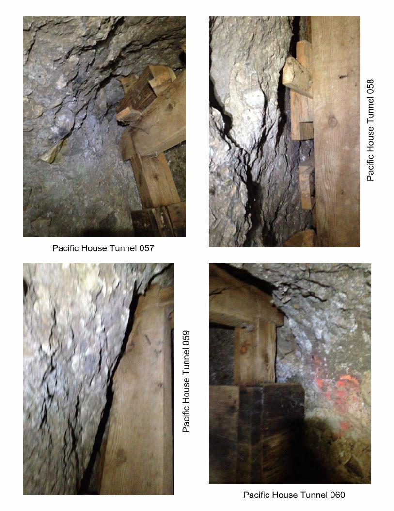
Pacific House Tunnel 057
Pac
ific
Hou
se T
unne
l 058
Pac
ific
Hou
se T
unne
l 059
Pacific House Tunnel 060
Pac
ific
Hou
se T
unne
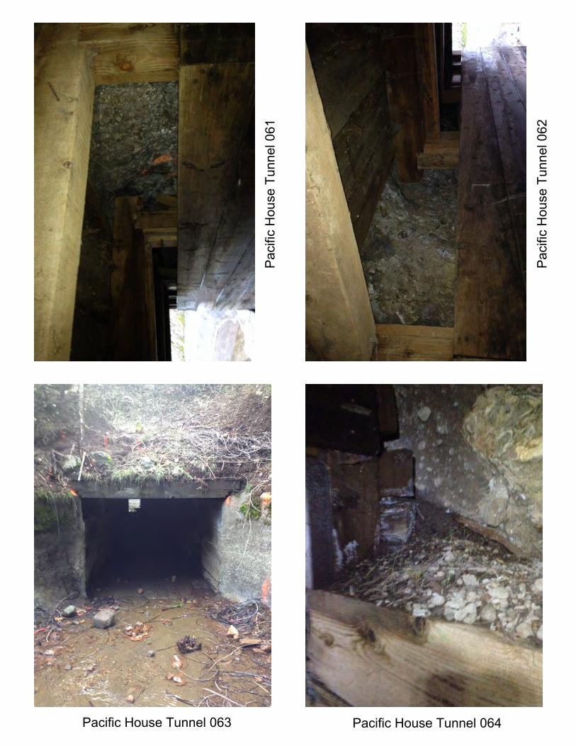
l 061
Pac
ific
Hou
se T
unne
l 062
Pacific House Tunnel 063 Pacific House Tunnel 064

Pacific House Tunnel 065 Pacific House Tunnel 066

GHD
4080 Plaza Goldorado Circle Suite B Cameron Park, CA 95682 USA T: 1 530 677 5515
© GHD Inc 2018
This document is and shall remain the property of GHD. The document may only be used for the purpose for which it was commissioned and in accordance with the Terms of Engagement for the commission. Unauthorized use of this document in any form whatsoever is prohibited.