Embed Size (px)
Citation preview

36
APPENDIX D
GEOTECHNICAL INVESTIGATION RESULTS
OFFICE LOCATION POSTAL ADDRESS Unit 3 / 42 Machinery Drive PO Box 6885
Tweed Heads South NSW 2486 www.geotechinvestigations.com Tweed Heads South NSW 2486
Our Ref: JW:jw: GI 2039-a
2 June 2015
Gold Coral Pty Ltd
PO Box 3441
Australia Fair Southport QLD 4215
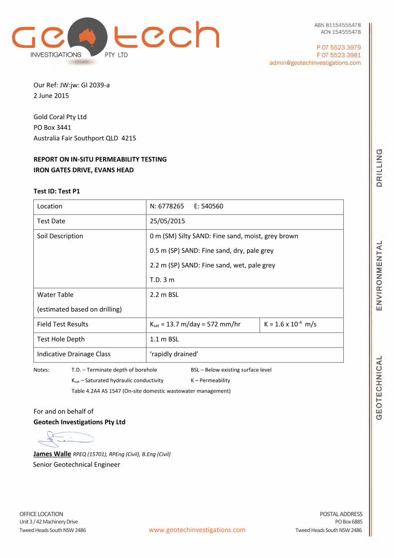
REPORT ON IN-SITU PERMEABILITY TESTING
IRON GATES DRIVE, EVANS HEAD
Test ID: Test P1
Location N: 6778265 E: 540560
Test Date 25/05/2015
Soil Description 0 m (SM) Silty SAND: Fine sand, moist, grey brown
0.5 m (SP) SAND: Fine sand, dry, pale grey
2.2 m (SP) SAND: Fine sand, wet, pale grey
T.D. 3 m
Water Table
(estimated based on drilling)
2.2 m BSL
Field Test Results Ksat = 13.7 m/day = 572 mm/hr K = 1.6 x 10⁻⁴ m/s
Test Hole Depth 1.1 m BSL
Indicative Drainage Class ‘rapidly drained’
Notes: T.D. – Terminate depth of borehole BSL – Below existing surface level
Ksat – Saturated hydraulic conductivity K – Permeability
Table 4.2A4 AS 1547 (On-site domestic wastewater management)
For and on behalf of
Geotech Investigations Pty Ltd
James Walle RPEQ (15701), RPEng (Civil), B.Eng (Civil)
Senior Geotechnical Engineer
OFFICE LOCATION POSTAL ADDRESS Unit 3 / 42 Machinery Drive PO Box 6885
Tweed Heads South NSW 2486 www.geotechinvestigations.com Tweed Heads South NSW 2486
Our Ref: JW:jw: GI 2039-b
2 June 2015
Gold Coral Pty Ltd
PO Box 3441
Australia Fair Southport QLD 4215
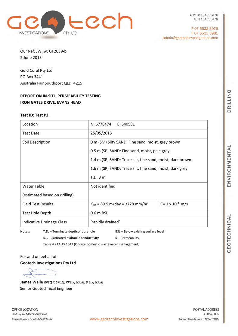
REPORT ON IN-SITU PERMEABILITY TESTING
IRON GATES DRIVE, EVANS HEAD
Test ID: Test P2
Location N: 6778474 E: 540581
Test Date 25/05/2015
Soil Description 0 m (SM) Silty SAND: Fine sand, moist, grey brown
0.5 m (SP) SAND: Fine sand, moist, pale grey
1.4 m (SP) SAND: Trace silt, fine sand, moist, dark brown
1.6 m (SP) SAND: Trace silt, fine sand, moist, dark grey
T.D. 3 m
Water Table
(estimated based on drilling)
Not identified
Field Test Results Ksat = 89.5 m/day = 3728 mm/hr K = 1 x 10⁻³ m/s
Test Hole Depth 0.6 m BSL
Indicative Drainage Class ‘rapidly drained’
Notes: T.D. – Terminate depth of borehole BSL – Below existing surface level
Ksat – Saturated hydraulic conductivity K – Permeability
Table 4.2A4 AS 1547 (On-site domestic wastewater management)
For and on behalf of
Geotech Investigations Pty Ltd
James Walle RPEQ (15701), RPEng (Civil), B.Eng (Civil)
Senior Geotechnical Engineer

OFFICE LOCATION POSTAL ADDRESS Unit 3 / 42 Machinery Drive PO Box 6885
Tweed Heads South NSW 2486 www.geotechinvestigations.com Tweed Heads South NSW 2486
Our Ref: JW:jw: GI 2039-c
2 June 2015
Gold Coral Pty Ltd
PO Box 3441
Australia Fair Southport QLD 4215
REPORT ON IN-SITU PERMEABILITY TESTING
IRON GATES DRIVE, EVANS HEAD
Test ID: Test P3
Location N: 6778597 E: 540503
Test Date 25/05/2015
Soil Description 0 m (SP) SAND: With silt, fine sand, moist, grey
0.3 m (SM) Silty SAND: Fine sand, moist, dark brown
0.6 m (SP) SAND: Trace silt, fine sand, wet, pale grey
1.4 m (SP) SAND: Trace silt, fine sand, wet, dark brown
T.D. 3 m
Water Table
(estimated based on drilling)
0.6 m BSL
Field Test Results Ksat = 16.8 m/day = 698 mm/hr K = 1.9 x 10⁻⁴ m/s
Test Hole Depth 0.17 m BSL
Indicative Drainage Class ‘rapidly drained’
Notes: T.D. – Terminate depth of borehole BSL – Below existing surface level
Ksat – Saturated hydraulic conductivity K – Permeability
Table 4.2A4 AS 1547 (On-site domestic wastewater management)
For and on behalf of
Geotech Investigations Pty Ltd
James Walle RPEQ (15701), RPEng (Civil), B.Eng (Civil)
Senior Geotechnical Engineer

OFFICE LOCATION POSTAL ADDRESS Unit 3 / 42 Machinery Drive PO Box 6885
Tweed Heads South NSW 2486 www.geotechinvestigations.com Tweed Heads South NSW 2486
Our Ref: JW:jw: GI 2039-d
2 June 2015
Gold Coral Pty Ltd
PO Box 3441
Australia Fair Southport QLD 4215
REPORT ON IN-SITU PERMEABILITY TESTING
IRON GATES DRIVE, EVANS HEAD
Test ID: Test P4
Location N: 6778425 E: 540493
Test Date 25/05/2015
Soil Description 0 m (SM) Silty SAND: Fine to medium sand, moist, dark brown
0.7 m (SP) SAND: Trace silt, fine sand, moist, pale grey
1.7 m (SP) SAND: Trace silt, fine sand, wet, pale grey
2.0 m (SP) SAND: Trace silt, fine sand, wet, grey brown
T.D. 3 m
Water Table
(estimated based on drilling)
1.7 m BSL
Field Test Results Ksat = 27.0 m/day = 1128 mm/hr K = 3.1 x 10⁻⁴ m/s
Test Hole Depth 0.77 m BSL
Indicative Drainage Class ‘rapidly drained’
Notes: T.D. – Terminate depth of borehole BSL – Below existing surface level
Ksat – Saturated hydraulic conductivity K – Permeability
Table 4.2A4 AS 1547 (On-site domestic wastewater management)
For and on behalf of
Geotech Investigations Pty Ltd
James Walle RPEQ (15701), RPEng (Civil), B.Eng (Civil)
Senior Geotechnical Engineer
OFFICE LOCATION POSTAL ADDRESS Unit 3 / 42 Machinery Drive PO Box 6885
Tweed Heads South NSW 2486 www.geotechinvestigations.com Tweed Heads South NSW 2486
Our Ref: JW:jw: GI 2039-e
2 June 2015
Gold Coral Pty Ltd
PO Box 3441
Australia Fair Southport QLD 4215
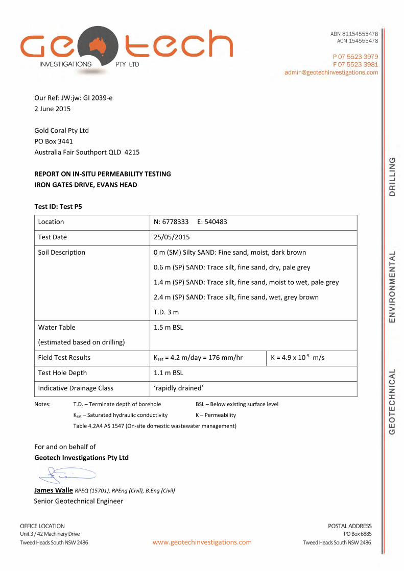
REPORT ON IN-SITU PERMEABILITY TESTING
IRON GATES DRIVE, EVANS HEAD
Test ID: Test P5
Location N: 6778333 E: 540483
Test Date 25/05/2015
Soil Description 0 m (SM) Silty SAND: Fine sand, moist, dark brown
0.6 m (SP) SAND: Trace silt, fine sand, dry, pale grey
1.4 m (SP) SAND: Trace silt, fine sand, moist to wet, pale grey
2.4 m (SP) SAND: Trace silt, fine sand, wet, grey brown
T.D. 3 m
Water Table
(estimated based on drilling)
1.5 m BSL
Field Test Results Ksat = 4.2 m/day = 176 mm/hr K = 4.9 x 10⁻⁵ m/s
Test Hole Depth 1.1 m BSL
Indicative Drainage Class ‘rapidly drained’
Notes: T.D. – Terminate depth of borehole BSL – Below existing surface level
Ksat – Saturated hydraulic conductivity K – Permeability
Table 4.2A4 AS 1547 (On-site domestic wastewater management)
For and on behalf of
Geotech Investigations Pty Ltd
James Walle RPEQ (15701), RPEng (Civil), B.Eng (Civil)
Senior Geotechnical Engineer
OFFICE LOCATION POSTAL ADDRESS Unit 3 / 42 Machinery Drive PO Box 6885
Tweed Heads South NSW 2486 www.geotechinvestigations.com Tweed Heads South NSW 2486
Our Ref: JW:jw: GI 2039-f
2 June 2015
Gold Coral Pty Ltd
PO Box 3441
Australia Fair Southport QLD 4215
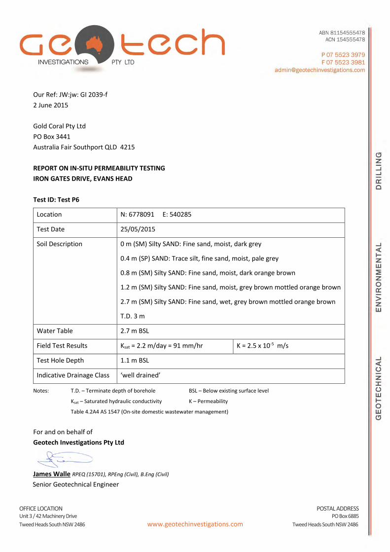
REPORT ON IN-SITU PERMEABILITY TESTING
IRON GATES DRIVE, EVANS HEAD
Test ID: Test P6
Location N: 6778091 E: 540285
Test Date 25/05/2015
Soil Description 0 m (SM) Silty SAND: Fine sand, moist, dark grey
0.4 m (SP) SAND: Trace silt, fine sand, moist, pale grey
0.8 m (SM) Silty SAND: Fine sand, moist, dark orange brown
1.2 m (SM) Silty SAND: Fine sand, moist, grey brown mottled orange brown
2.7 m (SM) Silty SAND: Fine sand, wet, grey brown mottled orange brown
T.D. 3 m
Water Table 2.7 m BSL
Field Test Results Ksat = 2.2 m/day = 91 mm/hr K = 2.5 x 10⁻⁵ m/s
Test Hole Depth 1.1 m BSL
Indicative Drainage Class ‘well drained’
Notes: T.D. – Terminate depth of borehole BSL – Below existing surface level
Ksat – Saturated hydraulic conductivity K – Permeability
Table 4.2A4 AS 1547 (On-site domestic wastewater management)
For and on behalf of
Geotech Investigations Pty Ltd
James Walle RPEQ (15701), RPEng (Civil), B.Eng (Civil)
Senior Geotechnical Engineer
OFFICE LOCATION POSTAL ADDRESS Unit 3 / 42 Machinery Drive PO Box 6885
Tweed Heads South NSW 2486 www.geotechinvestigations.com Tweed Heads South NSW 2486
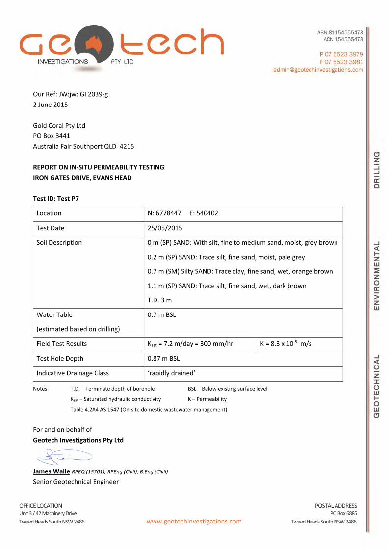
Our Ref: JW:jw: GI 2039-g
2 June 2015
Gold Coral Pty Ltd
PO Box 3441
Australia Fair Southport QLD 4215
REPORT ON IN-SITU PERMEABILITY TESTING
IRON GATES DRIVE, EVANS HEAD
Test ID: Test P7
Location N: 6778447 E: 540402
Test Date 25/05/2015
Soil Description 0 m (SP) SAND: With silt, fine to medium sand, moist, grey brown
0.2 m (SP) SAND: Trace silt, fine sand, moist, pale grey
0.7 m (SM) Silty SAND: Trace clay, fine sand, wet, orange brown
1.1 m (SP) SAND: Trace silt, fine sand, wet, dark brown
T.D. 3 m
Water Table
(estimated based on drilling)
0.7 m BSL
Field Test Results Ksat = 7.2 m/day = 300 mm/hr K = 8.3 x 10⁻⁵ m/s
Test Hole Depth 0.87 m BSL
Indicative Drainage Class ‘rapidly drained’
Notes: T.D. – Terminate depth of borehole BSL – Below existing surface level
Ksat – Saturated hydraulic conductivity K – Permeability
Table 4.2A4 AS 1547 (On-site domestic wastewater management)
For and on behalf of
Geotech Investigations Pty Ltd
James Walle RPEQ (15701), RPEng (Civil), B.Eng (Civil)
Senior Geotechnical Engineer
OFFICE LOCATION POSTAL ADDRESS Unit 3 / 42 Machinery Drive PO Box 6885
Tweed Heads South NSW 2486 www.geotechinvestigations.com Tweed Heads South NSW 2486
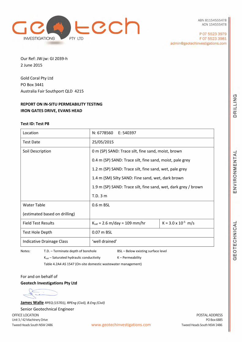
Our Ref: JW:jw: GI 2039-h
2 June 2015
Gold Coral Pty Ltd
PO Box 3441
Australia Fair Southport QLD 4215
REPORT ON IN-SITU PERMEABILITY TESTING
IRON GATES DRIVE, EVANS HEAD
Test ID: Test P8
Location N: 6778560 E: 540397
Test Date 25/05/2015
Soil Description 0 m (SP) SAND: Trace silt, fine sand, moist, brown
0.4 m (SP) SAND: Trace silt, fine sand, moist, pale grey
1.2 m (SP) SAND: Trace silt, fine sand, wet, pale grey
1.4 m (SM) Silty SAND: Fine sand, wet, dark brown
1.9 m (SP) SAND: Trace silt, fine sand, wet, dark grey / brown
T.D. 3 m
Water Table
(estimated based on drilling)
0.6 m BSL
Field Test Results Ksat = 2.6 m/day = 109 mm/hr K = 3.0 x 10⁻⁵ m/s
Test Hole Depth 0.07 m BSL
Indicative Drainage Class ‘well drained’
Notes: T.D. – Terminate depth of borehole BSL – Below existing surface level
Ksat – Saturated hydraulic conductivity K – Permeability
Table 4.2A4 AS 1547 (On-site domestic wastewater management)
For and on behalf of
Geotech Investigations Pty Ltd
James Walle RPEQ (15701), RPEng (Civil), B.Eng (Civil)
Senior Geotechnical Engineer
OFFICE LOCATION POSTAL ADDRESS Unit 3 / 42 Machinery Drive PO Box 6885
Tweed Heads South NSW 2486 www.geotechinvestigations.com Tweed Heads South NSW 2486
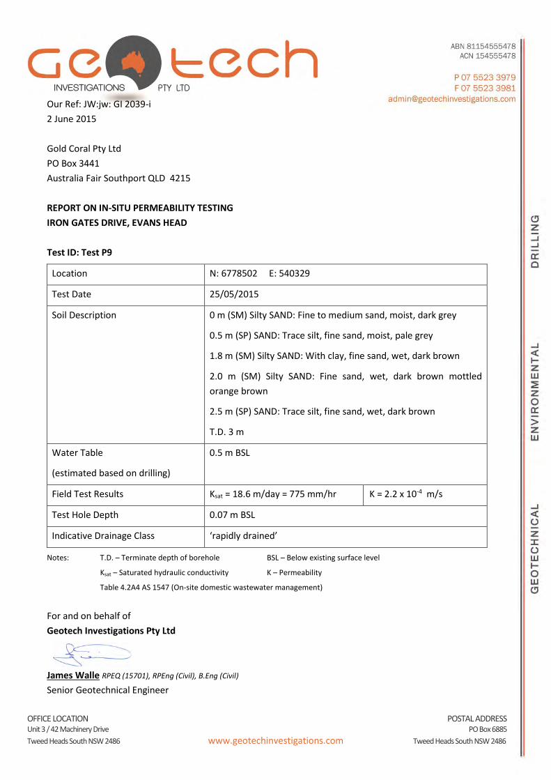
Our Ref: JW:jw: GI 2039-i
2 June 2015
Gold Coral Pty Ltd
PO Box 3441
Australia Fair Southport QLD 4215
REPORT ON IN-SITU PERMEABILITY TESTING
IRON GATES DRIVE, EVANS HEAD
Test ID: Test P9
Location N: 6778502 E: 540329
Test Date 25/05/2015
Soil Description 0 m (SM) Silty SAND: Fine to medium sand, moist, dark grey
0.5 m (SP) SAND: Trace silt, fine sand, moist, pale grey
1.8 m (SM) Silty SAND: With clay, fine sand, wet, dark brown
2.0 m (SM) Silty SAND: Fine sand, wet, dark brown mottled
orange brown
2.5 m (SP) SAND: Trace silt, fine sand, wet, dark brown
T.D. 3 m
Water Table
(estimated based on drilling)
0.5 m BSL
Field Test Results Ksat = 18.6 m/day = 775 mm/hr K = 2.2 x 10⁻⁴ m/s
Test Hole Depth 0.07 m BSL
Indicative Drainage Class ‘rapidly drained’
Notes: T.D. – Terminate depth of borehole BSL – Below existing surface level
Ksat – Saturated hydraulic conductivity K – Permeability
Table 4.2A4 AS 1547 (On-site domestic wastewater management)
For and on behalf of
Geotech Investigations Pty Ltd
James Walle RPEQ (15701), RPEng (Civil), B.Eng (Civil)
Senior Geotechnical Engineer

37
APPENDIX E
ADDITIONAL RFI – RESPONSE 11/05/2016
Registered office: Level 5, 141 Walker Street, North Sydney NSW 2060, Australia ABN 76 104 485 289 F:\AA007094\A-Correspondance\A0002-AA007094-AAL-01 - Additional RFI Response.docx
Graeme Ingles
Gold Coral c/- Ingles Group Pty Ltd
Po Box 558
Surfers Paradise QLD 4271
11/05/2016
Iron Gates Residential Subdivision – Response to Richmond Valley
Council Request for Further Information
Dear Graeme
We refer to the Information Request issued by Richmond Valley Council and the Office of
Environment & Heritage for the abovementioned development on 1st of March 2016
reference DA2015/096 –SMc:SL and our subsequent fee. In accordance with our
approved scope of works, this is our response (in orange font) to the request for
information items (in black font) for your inclusion in the collated response to Council.
1. Section 3.2; The 6.25 metre retaining wall is considered visually excessive.
Council requires a stepped embankment be provided. Please provide a revised
design detail for this request.
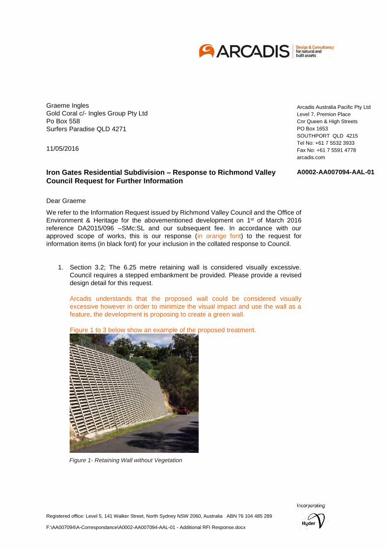
Arcadis understands that the proposed wall could be considered visually
excessive however in order to minimize the visual impact and use the wall as a
feature, the development is proposing to create a green wall.
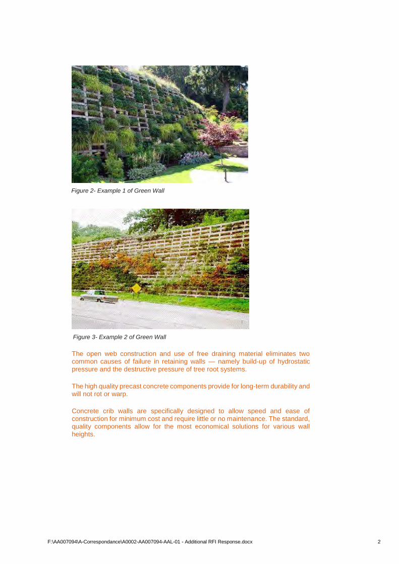
Figure 1 to 3 below show an example of the proposed treatment.
Figure 1- Retaining Wall without Vegetation
Arcadis Australia Pacific Pty Ltd
Level 7, Premion Place
Cnr Queen & High Streets
PO Box 1653
SOUTHPORT QLD 4215
Tel No: +61 7 5532 3933
Fax No: +61 7 5591 4778
arcadis.com
A0002-AA007094-AAL-01
F:\AA007094\A-Correspondance\A0002-AA007094-AAL-01 - Additional RFI Response.docx 2
Figure 2- Example 1 of Green Wall
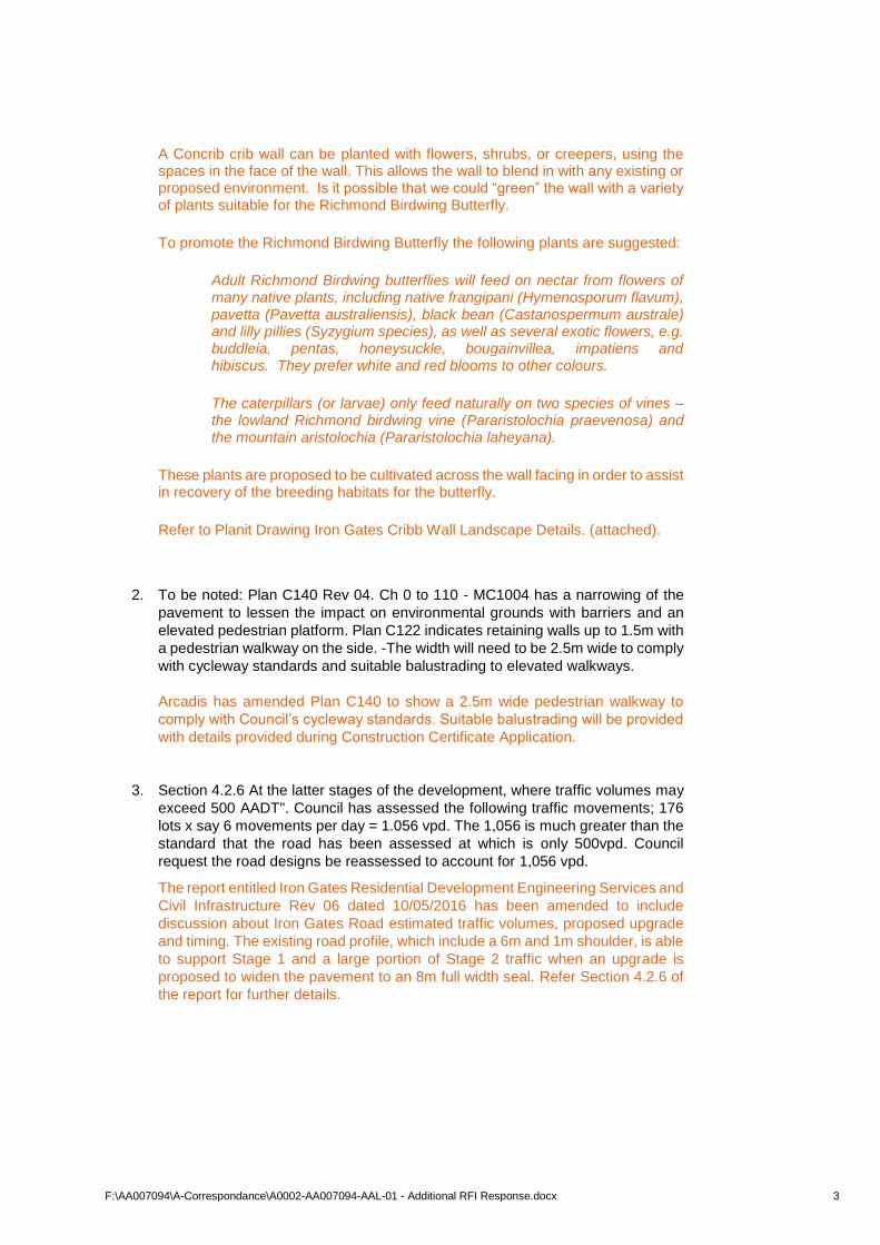
Figure 3- Example 2 of Green Wall
The open web construction and use of free draining material eliminates two common causes of failure in retaining walls — namely build-up of hydrostatic pressure and the destructive pressure of tree root systems.
The high quality precast concrete components provide for long-term durability and will not rot or warp.
Concrete crib walls are specifically designed to allow speed and ease of construction for minimum cost and require little or no maintenance. The standard, quality components allow for the most economical solutions for various wall heights.
F:\AA007094\A-Correspondance\A0002-AA007094-AAL-01 - Additional RFI Response.docx 3
A Concrib crib wall can be planted with flowers, shrubs, or creepers, using the spaces in the face of the wall. This allows the wall to blend in with any existing or proposed environment. Is it possible that we could “green” the wall with a variety of plants suitable for the Richmond Birdwing Butterfly.
To promote the Richmond Birdwing Butterfly the following plants are suggested:
Adult Richmond Birdwing butterflies will feed on nectar from flowers of many native plants, including native frangipani (Hymenosporum flavum), pavetta (Pavetta australiensis), black bean (Castanospermum australe) and lilly pillies (Syzygium species), as well as several exotic flowers, e.g. buddleia, pentas, honeysuckle, bougainvillea, impatiens and hibiscus. They prefer white and red blooms to other colours.
The caterpillars (or larvae) only feed naturally on two species of vines – the lowland Richmond birdwing vine (Pararistolochia praevenosa) and the mountain aristolochia (Pararistolochia laheyana).
These plants are proposed to be cultivated across the wall facing in order to assist in recovery of the breeding habitats for the butterfly.
Refer to Planit Drawing Iron Gates Cribb Wall Landscape Details. (attached).
2. To be noted: Plan C140 Rev 04. Ch 0 to 110 - MC1004 has a narrowing of the
pavement to lessen the impact on environmental grounds with barriers and an
elevated pedestrian platform. Plan C122 indicates retaining walls up to 1.5m with
a pedestrian walkway on the side. -The width will need to be 2.5m wide to comply
with cycleway standards and suitable balustrading to elevated walkways.
Arcadis has amended Plan C140 to show a 2.5m wide pedestrian walkway to
comply with Council’s cycleway standards. Suitable balustrading will be provided
with details provided during Construction Certificate Application.
3. Section 4.2.6 At the latter stages of the development, where traffic volumes may
exceed 500 AADT". Council has assessed the following traffic movements; 176
lots x say 6 movements per day = 1.056 vpd. The 1,056 is much greater than the
standard that the road has been assessed at which is only 500vpd. Council
request the road designs be reassessed to account for 1,056 vpd.
The report entitled Iron Gates Residential Development Engineering Services and
Civil Infrastructure Rev 06 dated 10/05/2016 has been amended to include
discussion about Iron Gates Road estimated traffic volumes, proposed upgrade
and timing. The existing road profile, which include a 6m and 1m shoulder, is able
to support Stage 1 and a large portion of Stage 2 traffic when an upgrade is
proposed to widen the pavement to an 8m full width seal. Refer Section 4.2.6 of
the report for further details.
F:\AA007094\A-Correspondance\A0002-AA007094-AAL-01 - Additional RFI Response.docx 4
4. Section 9.2.2; please explain what is the comparison between the original ET
loading that was the input for the dual rising main, and the proposed ET loading
now by the proposed subdivision. Council needs to ensure the existing
infrastructure is suitably sized for the proposed development.
The report entitled Iron Gates Residential Development Engineering Services and
Civil Infrastructure Rev 06 dated 10/05/2016 has been amended to make
allowance for the existing lots, currently connected to the DN150 gravity sewer in
Mangrove Street upstream of the existing EHPS-02 pump station. Please refer to
attached sewer calculations and Section 9 of the report.
5. Section 7.2.3 Infiltration pits are 1m deep and almost 5m2 . Council has concerns;
• What are the risks to a saturated sub base for the roads?
To avoid any risks of saturating road sub-base, all roads will be provided with
subsurface drainage in accordance with The Northern River Council Specs.
• Impact to/from driveways?
Driveways will be coordinated during detailed design to avoid clashes with
drainage system.
• How is overflow from the pits to be managed without causing nuisance
stormwater flows to adjoining land owners. Council preference is for the
overflow to be discharged to street kerb or via Internal Allotment Drainage
(IAD).
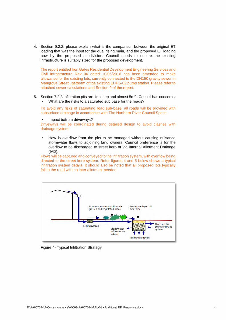
Flows will be captured and conveyed to the infiltration system, with overflow being
directed to the street kerb system. Refer figures 4 and 5 below shows a typical
infiltration system details. It should also be noted that all proposed lots typically
fall to the road with no inter allotment needed.
Figure 4- Typical Infiltration Strategy
F:\AA007094\A-Correspondance\A0002-AA007094-AAL-01 - Additional RFI Response.docx 5
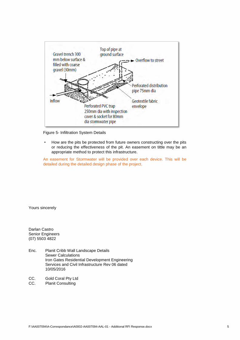
Figure 5- Infiltration System Details
• How are the pits be protected from future owners constructing over the pits
or reducing the effectiveness of the pit. An easement on tittle may be an
appropriate method to protect this infrastructure.
An easement for Stormwater will be provided over each device. This will be
detailed during the detailed design phase of the project.
Yours sincerely
Darlan Castro Senior Engineers (07) 5503 4822
Enc. Planit Cribb Wall Landscape Details Sewer Calculations
Iron Gates Residential Development Engineering Services and Civil Infrastructure Rev 06 dated 10/05/2016
CC. Gold Coral Pty Ltd
CC. Planit Consulting

38
APPENDIX F
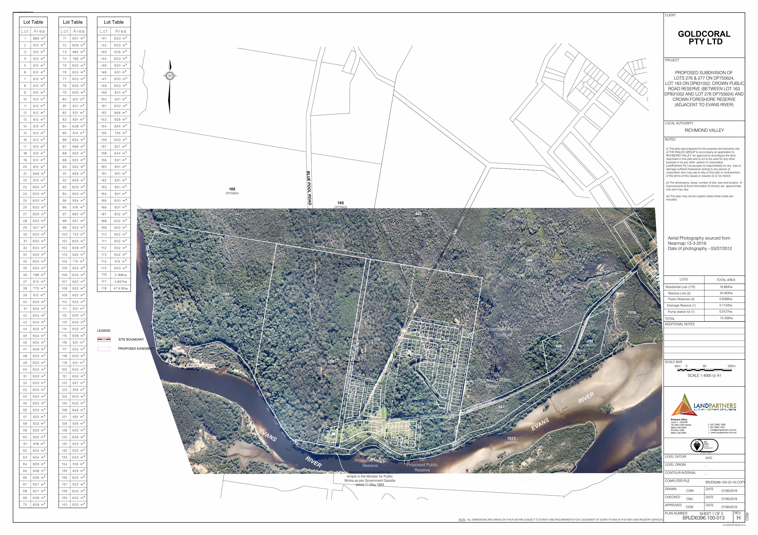
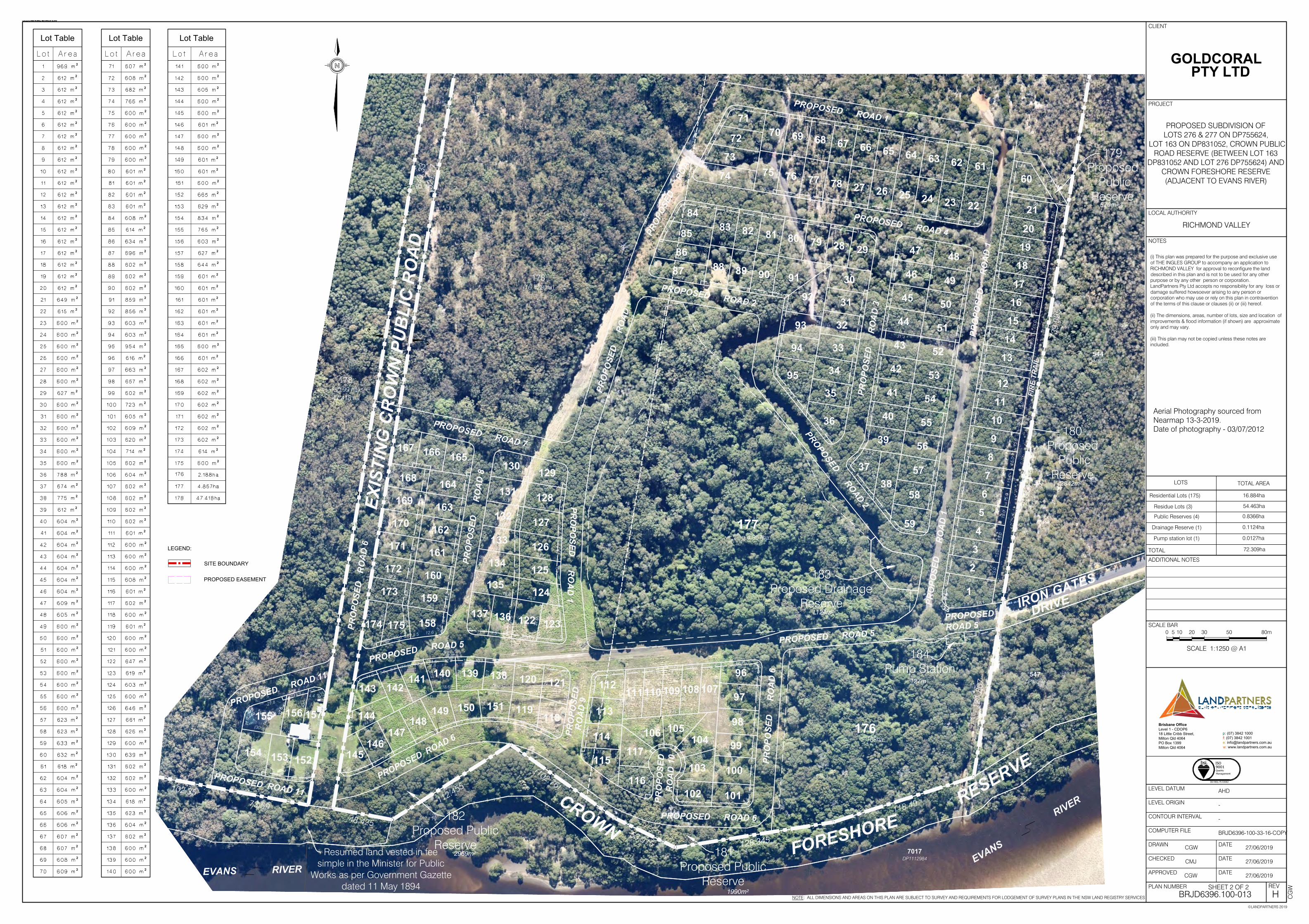
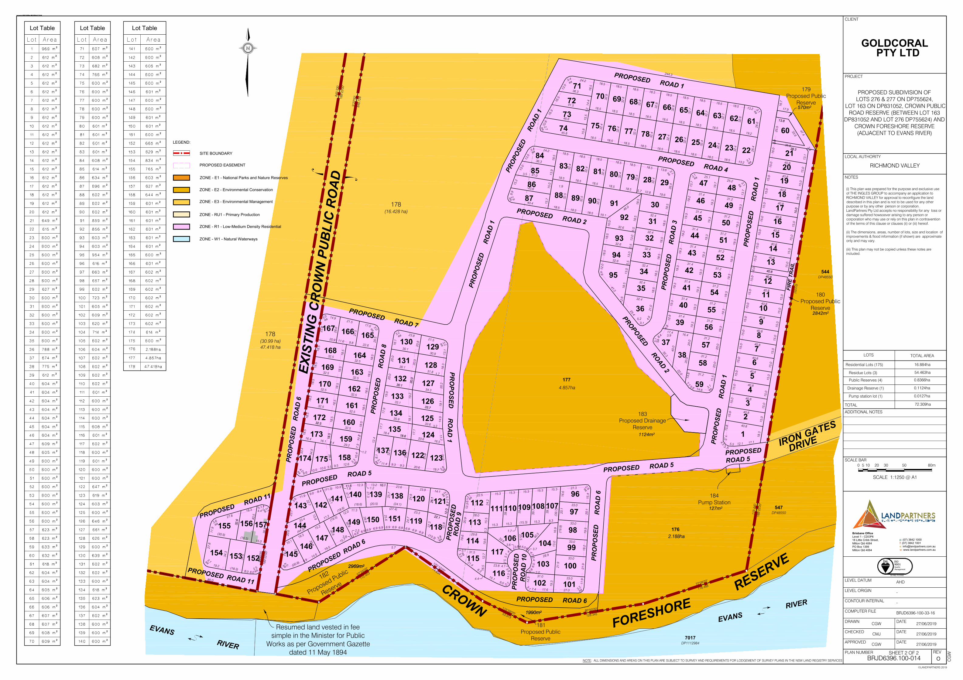
AMENDED SUBDIVSION PLANS
PROPOSED ROAD 2
FIR
E TR
AIL
PRO
POSE
DRO
AD 1
274.
715
603.
15
402.3420.115
503.32
849.
3352
1.17
29.20594.26
65.2
59.92
66.58
26.38
9.65
5 102.35
48.425
112.455(102.76)
53.915 128.345
118.4973.59
121.
867
(739
.995
)
21
156
157
163
161
164
160
162
33
130
49
60
4
5
6
7
8
9
91
17
13
18
50
86
93
165
166
134
131
128
127
132
126
135
125
133
110
107108
109
111
106
105
114
113
124
2
3
51
38
10
12
11
14
15
16
19
20
48
52
59
56
40
55
54
41
53
42
43
44
45
46
47
83
82
85
81
80
92
79
28
29
36
35
34
32
31
30
84
22
23
24
25
26
27
78
77
76
75
73
72
39
57
58
1
37
153
152
88
90
89
94
95
129
159
121
175
158
136
122
137
123
112
97
101
100
99
98
96
74
87
167
174
173
172
171
170
169
168
143
102
115
104
116
103
117
70
69
68
67
66
65
64
63
62
71
61
144
141 120
139140
142
149
138
119
148
147
150
118
151
146
145
155
154
PROPOSED ROAD 4
PROPOSED ROAD 1
PRO
POSE
DR
OA
D 1
PRO
POSE
DR
OA
D 3
PROP
OSED
ROAD
1
PRO
POSE
DR
OA
D 1
PROPOSEDROAD 2
PROPOSED ROAD 7
PRO
POSE
DR
OA
D 8
PRO
POSE
DR
OA
D 6
PRO
POSED
RO
AD
1
PROPOSED ROAD 5
PROPOSED ROAD 11
PROPOSED ROAD 5PR
OPO
SED
RO
AD
6
PROPOSEDROAD 5
PRO
POSE
DR
OA
D 1
0
PROPOSED ROAD 6
PRO
POSE
DR
OA
D 9
PROPOSED ROAD 6
PROPOSED ROAD 11
IRON GATES
DRIVE
IRON GATES
DRIVE
WATTLE ST
EXIS
TIN
G C
RO
WN
PU
BLI
C R
OA
D
CROWNFORESHORE
RESERVE
©LANDPARTNERS 2019
REV
APPROVED
NOTE: ALL DIMENSIONS AND AREAS ON THIS PLAN ARE SUBJECT TO SURVEY AND REQUIREMENTS FOR LODGEMENT OF SURVEY PLANS IN THE NSW LAND REGISTRY SERVICES
PLAN NUMBER
DATE
DRAWN
CHECKED
COMPUTER FILE
CONTOUR INTERVAL
LEVEL ORIGIN
LEVEL DATUM
DATE
DATE
ADDITIONAL NOTES
SCALE BAR
PROJECT
LOCAL AUTHORITY
CLIENT
NOTES
BRJD6396.100-013
-
BRJD6396-100-33-16-COPY
CGW
-
AHD
GOLDCORAL
PTY LTD
(i) This plan was prepared for the purpose and exclusive useof THE INGLES GROUP to accompany an application toRICHMOND VALLEY for approval to reconfigure the landdescribed in this plan and is not to be used for any otherpurpose or by any other person or corporation.LandPartners Pty Ltd accepts no responsibility for any loss ordamage suffered howsoever arising to any person orcorporation who may use or rely on this plan in contraventionof the terms of this clause or clauses (ii) or (iii) hereof.
(ii) The dimensions, areas, number of lots, size and location ofimprovements & flood information (if shown) are approximateonly and may vary.
(iii) This plan may not be copied unless these notes areincluded.
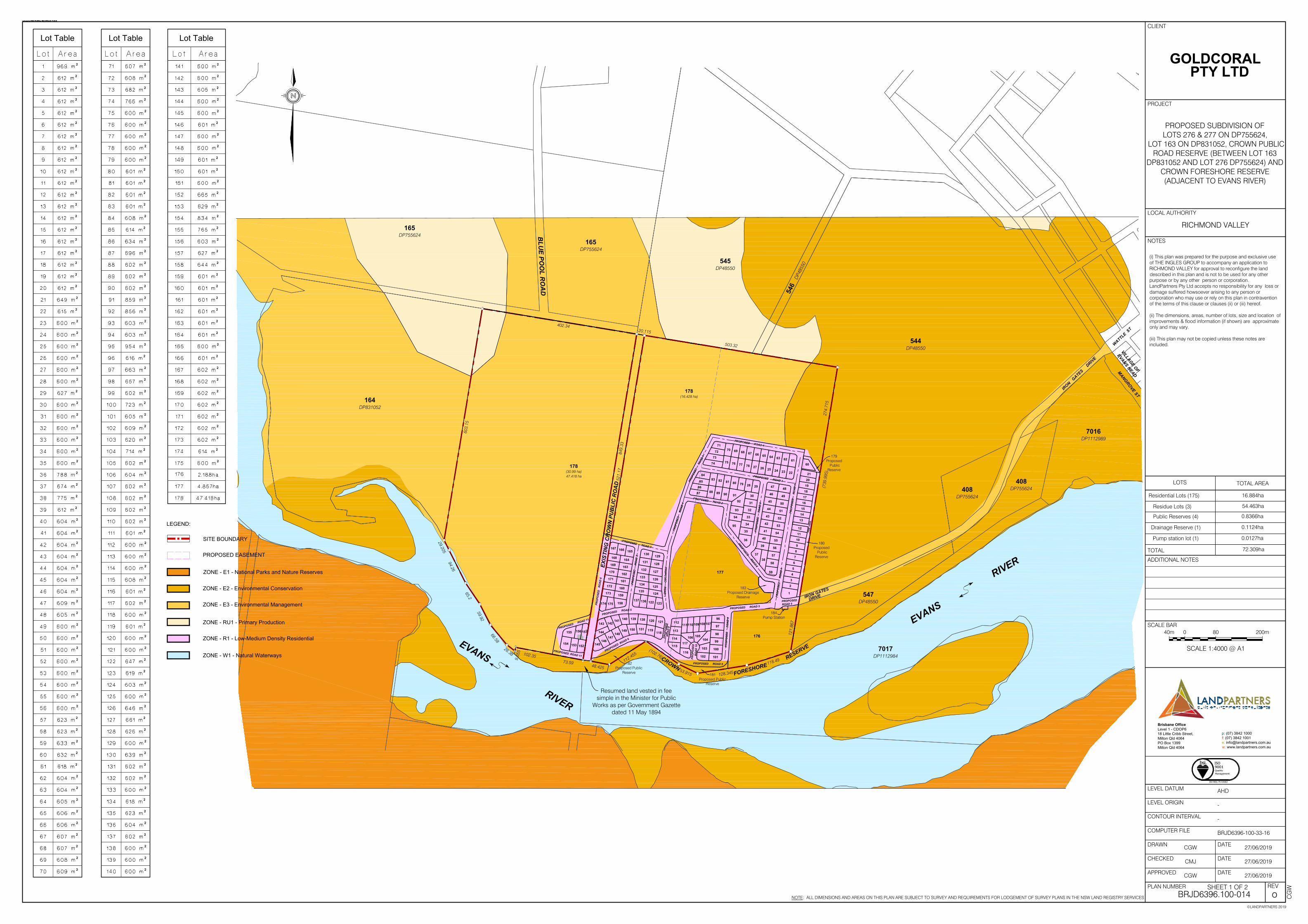
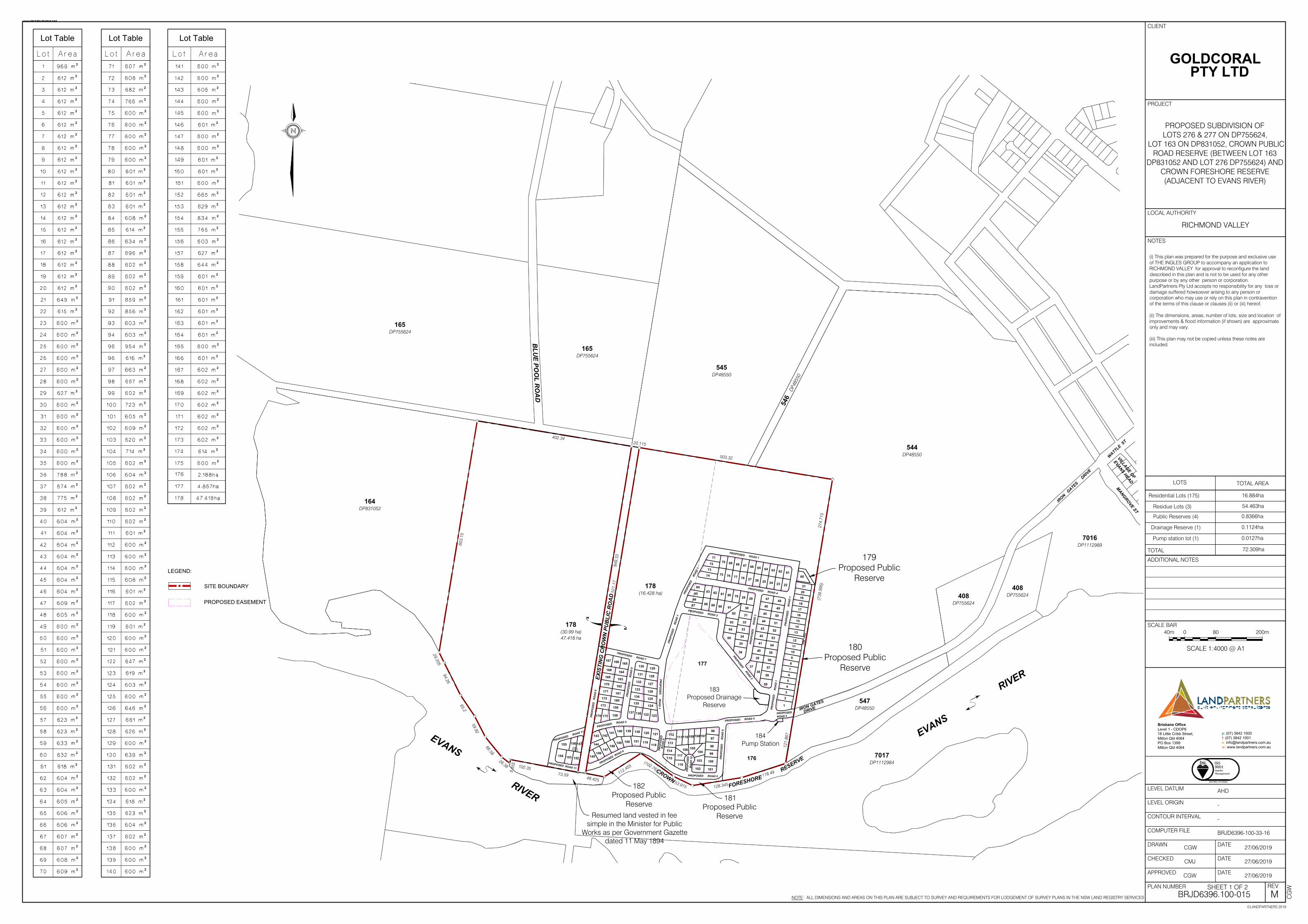
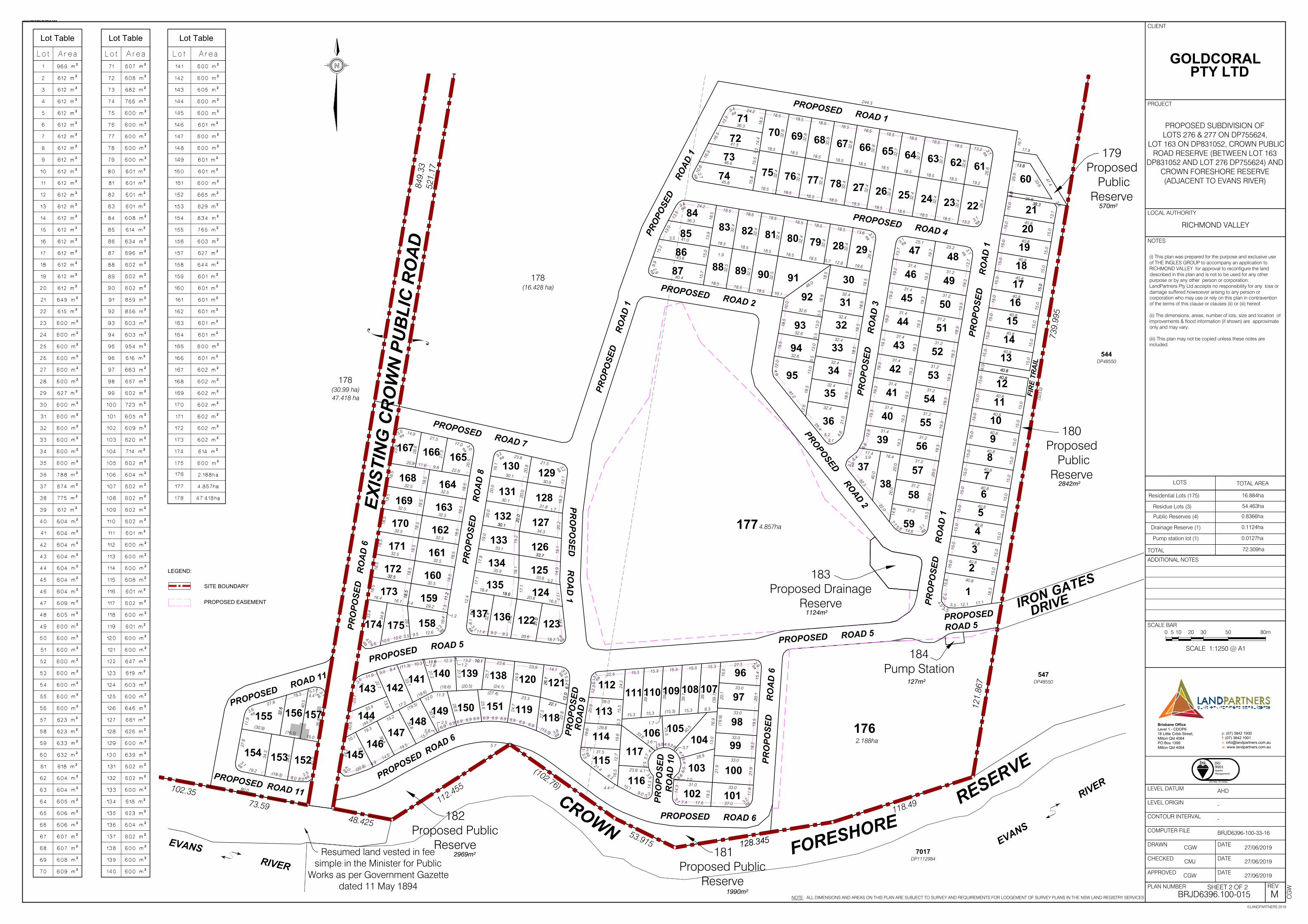
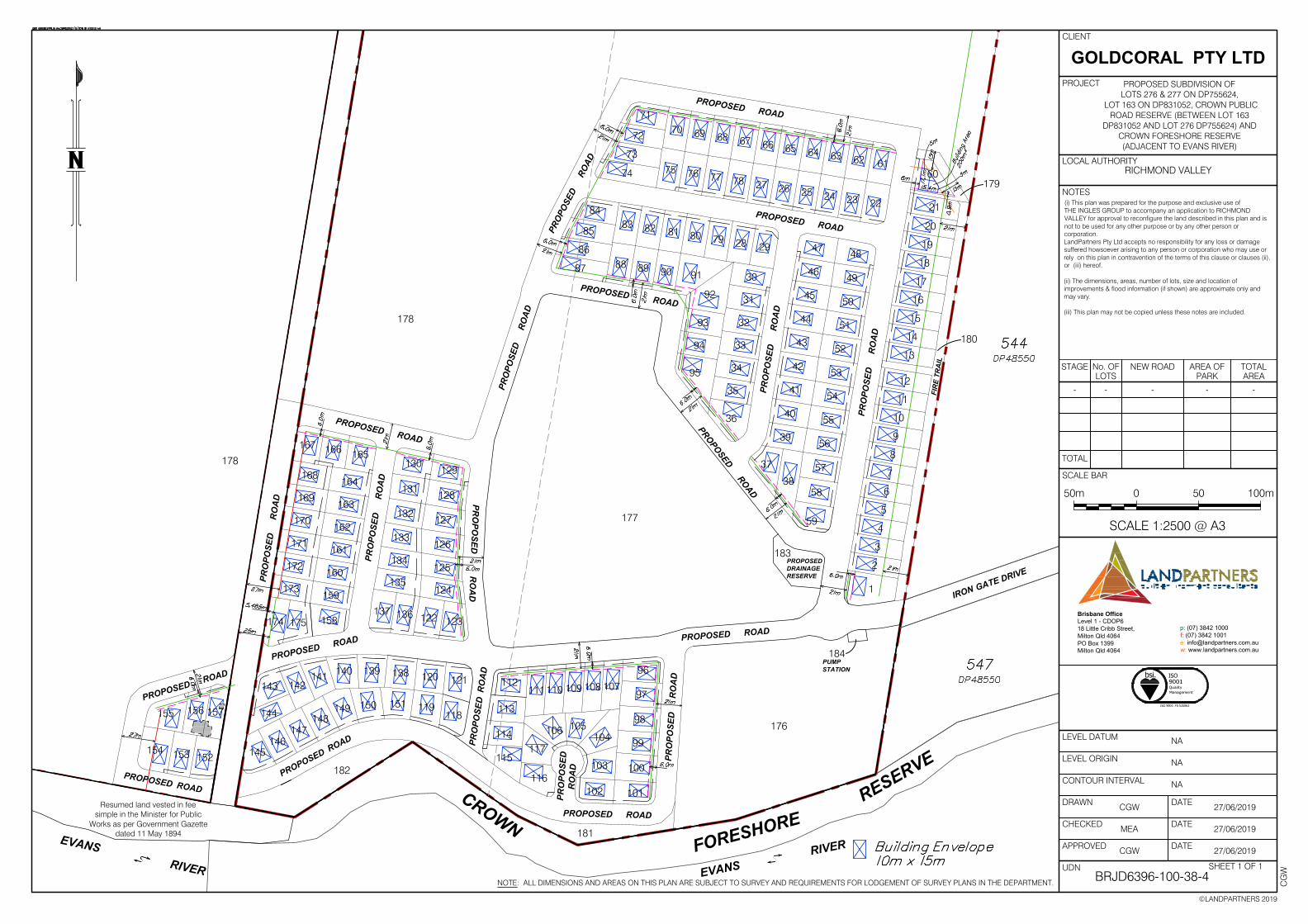
PROPOSED SUBDIVISION OFLOTS 276 & 277 ON DP755624,
LOT 163 ON DP831052, CROWN PUBLICROAD RESERVE (BETWEEN LOT 163
DP831052 AND LOT 276 DP755624) ANDCROWN FORESHORE RESERVE(ADJACENT TO EVANS RIVER)
RICHMOND VALLEY
H CG
W
Brisbane Office
Level 1 - CDOP6
18 Little Cribb Street,
Milton Qld 4064
PO Box 1399
Milton Qld 4064
p: (07) 3842 1000
f: (07) 3842 1001
w: www.landpartners.com.au
bsi.
ISO 9001: FS 535063
ISO9001QualityManagement
SITE BOUNDARY
PROPOSED EASEMENT
LEGEND:
27/06/2019
27/06/2019
27/06/2019
CMJ
CGW
Lot Table Lot Table Lot Table
180Proposed Public
Reserve
178
(30.99 ha)47.418 ha
178
(16.428 ha)
176
SCALE 1:4000 @ A1
40m 0 80 200m
SHEET 1 OF 2
179Proposed Public
Reserve
181Proposed Public
Reserve
182Proposed Public
Reserve
177
165
DP755624
165
DP755624
545
DP48550
544
DP48550
BLU
E POO
L RO
AD
547
DP48550
408
DP755624
408
DP755624
7016
DP1112989
VILLAGE OF
EVANS HEAD
7017
DP1112984
5
4
6
DP4
8550
MANGROVE ST
Aerial Photography sourced fromNearmap 13-3-2019.Date of photography - 03/07/2012
183Proposed Drainage
Reserve
EVANS
R
IVER
EVANS RIVER
TOTAL
LOTS TOTAL AREA
72.309ha
Residue Lots (3)
Residential Lots (175)
Public Reserves (4)
54.463ha
0.8366ha
16.884ha
Drainage Reserve (1) 0.1124ha
Resumed land vested in feesimple in the Minister for Public
Works as per Government Gazettedated 11 May 1894
164
DP831052
Pump station lot (1) 0.0127ha
184Pump Station
128.345
739.
995
48.425
(102.76)
53.915 128.345
118.49
102.35
PROPOSED ROAD 2
FIR
E TR
AIL
PRO
POSE
DRO
AD 1
178
(30.99 ha)47.418 ha
73.59112.455
121.
867
521.
17
849.
33
32.6
25.2 3.1
9.04.4
6.3
3.6
20.69.3
3.3
10.1
34.3
34.6
5.118.3
3.5
33.4
18.5
18.5
18.5
18.5
18.5
18.5
23.8
18.5
18.5
18.5
18.5
18.5
18.5
ea
8.0
(323
.0)
11.6
20.8
3.0
12.6
41.2
4.9
12.0
18.5
32.6
18.5
32.6
10.0
46.0
18.5
18.5
5.5
13.0
5.5
13.0
5.5
13.0
18.5
12.6
32.6
4.65.2
3.1
25.4
32.4
21.0
18.5
32.4
18.5
32.4
18.5
32.4
18.5
32.4
18.5
32.4
18.5
12.8 19.6
3.2 23.8
16.1
19.3
31.2
19.7
19.3
19.3
19.3
19.3
19.3
19.3
19.3
19.3
20.0
20.0
14.8
31.2
20.0
31.2
20.0
31.2
7.1
15.5
3.114.6
5.6
22.0
40.0
16.48.4 3.9
17.432.3
3.1
12.9 31.4
6.8
19.3
31.431.2
19.3
31.431.2
19.3
31.4
19.3
31.4
19.2
25.1
31.4
19.3
19.2
13.7
3.1
3.0
11.4
8.1
31.4 13.7
31.2
19.3
31.2
19.3
19.3
31.2
19.3
31.2
19.3
19.3
19.3
24.2
18.5
36.3
13.5
3.418.5
32.9
18.5
32.8
18.5
18.5
32.8
18.5
18.5
32.8
18.5
18.5
32.8
18.5
18.5
32.7
18.5
32.7
18.5
18.518.5
32.7
18.5
32.6
18.5
18.5 13.2 3.1
26.6
19.2
13.2
32.4
26.4
3.118.5
32.4
18.5
32.4
18.5
32.4
18.5
32.4
18.5
32.4
18.5
32.4
18.5
32.4
18.5
45.8
2.7
10.6
16.3
16.5
18.5
40.8
18.3
3.0
13.8
15.0
15.0
15.0
15.0
15.0
15.0
15.0
15.0
15.0
15.0
40.8
15.0
15.0
15.0
15.0
40.8
40.8
40.8
40.8
40.8
40.8
40.8
40.8
40.8
40.4
9.9
43.6
15.2
3.5
13.0
41.0
36.3 18.5
13.9
1.9
18.5
32.5
18.5
32.5
18.5
32.5
18.518.5 5.7
10.118.5
18.518.5
24.2
13.5
3.418.5
32.4
18.5
32.4
18.5
32.4 13.6 3.1
26.4
18.5
32.4
32.4
32.4
40.8
16.0 38.3
13.1
3.8
40.8
15.0
40.8
15.0
40.8
15.0 40.8
15.0
40.8
15.0
40.8
15.0
40.8
15.0
40.8
15.0
27.5
22.69.8
20.9
34.9
8.610.64.0
14.921.5
29.23.4
16.116.4
10.4
9.510.6
20.0
20.0
30.1
20.0
19.0
17.9
17.1
9.3
19.1
14.9
3.2
17.724.9
30.9
3.2
21.5
13.1
18.3
31.8
30.1
20.0
20.0
20.2
34.3
30.1
33.7
33.6
16.520.6
32.8
31.031.9
19.2
18.1
33.7
33.1
35.9
18.6
30.1
31.0
1.7
2.8
5.3
14.3
23.8
24.2
15.5
5.3
19.6
12.7
16.5
33.6
4.53.6 3.7
4.75.4
6.5
5.6 2.0
3.63.8
15.3 15.3
1.7
(15.3) 15.3 8.3
25.5 40.5
16.6
20.1
(39.
7)16
.913
.0 33.0
33.0
31.0 33.0
17.6 27.0
15.4
20.1
3.2
33.0
22.5 15.3 15.3 15.3 15.3 15.3 27.3
39.7 39
.7
39.7
39.7
2.9
33.0
3.1
19.6
20.9
12.3
29.8
31.5
28.0
3.1
21.4
17.1
18.618.4
18.5
18.5
18.5
18.5
18.5
20.5
11.9
21.9
18.2
19.9
28.9
21.9
19.3
2.9
40.8
15.0
15.0
15.0
15.7
15.5
14.4
1.2 18.5
32.4
15.8
46.6
41.5
32.532.5
32.532.5
32.532.5
32.532.5
32.5
32.5
17.9
3.8
4.0
47.4
15.0
15.0
40.8
6.0
40.8
15.0
15.0
15.0
15.0
15.0
15.0
15.0
15.0
38.3
3.0
25.5
35.8
33.6
13.8
31.2
31.4
244.3
28.6
11.6
11.2
12.4
7.3
18.5
32.5
11.2
3.3
26.4
15.0
15.0
15.0
15.0
1.2
18.7
18.518.5
17.0
14.3
7.4
3.1
2.7
15.1
4.1 3.8
4.7
5.2
5.7
16.7
ea
ea
ea
ea
ea
ea
ea
ea
ea
ea
ea
ea
ea
ea
ea
ea
ea
ea
ea
ea
ea
ea
eaea
ea
2.5ea8.0 8.0
27.5
ea
3.1
32.6 40
.5
15.0(16.5)
(30.9)
31.3
20.6
15.2
19.3
30.8
33.4
23.1
9.0
22.7
(11.3) 10.3
33.1
24.9
26.1
23.3
24.7
27.3
6.9 6.9
12.0
22.1
25.6
(24.1)
3.8
2.5
10.1
25.7
(20.5)
27.3
27.8
11.9
27.8
3.6
4.4
36.8
30.9
30.8
1.811.6
27.2
12.3 13.2
11.9
23.9
28.8
14.5
19.5
12.0
22.1
26.1
22.8
6.9 6.9 6.9
24.2
(20.9) 4.9
(18.3)19.2
5.7
8.423.6
80.0
6.9
15.7
6.96.96.96.9
6.9
(18.6)
12.0
(19.5)
10.1
13.9
(13.3)
1.214.1
3.1 (27.4)(18.6)
17.2
11.3
(44.3)
3.1ea
ea
ea
(19.
9)
21
156
157
163
161
164
160
162
33
130
49
60
4
5
6
7
8
9
91
17
13
18
50
86
93
165
166
134
131
128
127
132
126
135
125
133
110
107108
109
111
106
105
114
113
124
2
3
51
38
10
12
11
14
15
16
19
20
48
52
59
56
40
55
54
41
53
42
43
44
45
46
47
83
82
85
81
80
92
79
28
29
36
35
34
32
31
30
84
22
23
24
25
26
27
78
77
76
75
73
72
39
57
58
1
37
153
152
88
90
89
94
95
129
159
121
175
158
136
122
137
123
112
97
101
100
99
98
96
74
87
167
174
173
172
171
170
169
168
143
102
115
104
116
103
117
70
69
68
67
66
65
64
63
62
71
61
144
141 120
139140
142
149
138
119
148
147
150
118
151
146
145
155
154
PROPOSED ROAD 4
PROPOSED ROAD 1
PRO
POSE
DR
OA
D 1
PRO
POSE
DR
OA
D 3
PROP
OSED
ROAD
1
PRO
POSE
DR
OA
D 1
PROPOSEDROAD 2
PROPOSED ROAD 7
PRO
POSE
DR
OA
D 8
PRO
POSE
DR
OA
D 6
PRO
POSED
RO
AD
1
PROPOSED ROAD 5
PROPOSED ROAD 11
PROPOSED ROAD 5
PRO
POSE
DR
OA
D 6
PROPOSEDROAD 5
PRO
POSE
DR
OA
D 1
0
PROPOSED ROAD 6
PRO
POSE
DR
OA
D 9
PROPOSED ROAD 6
PROPOSED ROAD 11
176
181Proposed Public
Reserve
180Proposed
PublicReserve
182Proposed Public
Reserve
179Proposed
PublicReserve
177
IRON GATES
DRIVE
3.5
6.7
6.7
1.9
183Proposed Drainage
Reserve
EXIS
TIN
G C
RO
WN
PU
BLI
C R
OA
D
CROWNFORESHORE
RESERVE
184Pump Station
12.15.5
4.5
15.8
17.1
©LANDPARTNERS 2019
REV
APPROVED
NOTE: ALL DIMENSIONS AND AREAS ON THIS PLAN ARE SUBJECT TO SURVEY AND REQUIREMENTS FOR LODGEMENT OF SURVEY PLANS IN THE NSW LAND REGISTRY SERVICES
PLAN NUMBER
DATE
DRAWN
CHECKED
COMPUTER FILE
CONTOUR INTERVAL
LEVEL ORIGIN
LEVEL DATUM
DATE
DATE
ADDITIONAL NOTES
SCALE BAR
PROJECT
LOCAL AUTHORITY
CLIENT
NOTES
BRJD6396.100-013
-
BRJD6396-100-33-16-COPY
CGW
-
AHD
GOLDCORAL
PTY LTD
(i) This plan was prepared for the purpose and exclusive useof THE INGLES GROUP to accompany an application toRICHMOND VALLEY for approval to reconfigure the landdescribed in this plan and is not to be used for any otherpurpose or by any other person or corporation.LandPartners Pty Ltd accepts no responsibility for any loss ordamage suffered howsoever arising to any person orcorporation who may use or rely on this plan in contraventionof the terms of this clause or clauses (ii) or (iii) hereof.
(ii) The dimensions, areas, number of lots, size and location ofimprovements & flood information (if shown) are approximateonly and may vary.
(iii) This plan may not be copied unless these notes areincluded.
RICHMOND VALLEY
H CG
W
Brisbane Office
Level 1 - CDOP6
18 Little Cribb Street,
Milton Qld 4064
PO Box 1399
Milton Qld 4064
p: (07) 3842 1000
f: (07) 3842 1001
w: www.landpartners.com.au
bsi.
ISO 9001: FS 535063
ISO9001QualityManagement
SITE BOUNDARY
PROPOSED EASEMENT
LEGEND:
27/06/2019
27/06/2019
27/06/2019
CMJ
CGW
2.188ha
Lot Table Lot Table Lot Table
1990m²
178(30.99 ha)47.418 ha
178(16.428 ha)
2969m²
4.857ha
2842m²
570m²
0 5
SCALE 1:1250 @ A1
2010 30 50 80m
SHEET 2 OF 2
7017
DP1112984
547
DP48550
544
DP48550
Aerial Photography sourced fromNearmap 13-3-2019.Date of photography - 03/07/2012
EVANS
R
IVER
EVANS RIVER
PROPOSED SUBDIVISION OFLOTS 276 & 277 ON DP755624,
LOT 163 ON DP831052, CROWN PUBLICROAD RESERVE (BETWEEN LOT 163
DP831052 AND LOT 276 DP755624) ANDCROWN FORESHORE RESERVE(ADJACENT TO EVANS RIVER)
Resumed land vested in feesimple in the Minister for Public
Works as per Government Gazettedated 11 May 1894
1124m²
TOTAL
LOTS TOTAL AREA
72.309ha
Residue Lots (3)
Residential Lots (175)
Public Reserves (4)
54.463ha
0.8366ha
16.884ha
Drainage Reserve (1) 0.1124ha
Pump station lot (1) 0.0127ha
127m²
57°24'20"
112.453
125°12'20"74.834
115°59'20"53.913
80°50'20"
128.345
72°09'20"
118.488
189°
22'2
0"
119.
440
9°22
'00"
848.
72818
9°22
'00"
849.
330
189°
22'0
0"
849.
330
PROPOSED ROAD 2
FIR
E TR
AIL
PRO
POSE
DRO
AD 1
32.6
25.2 3.1
9.04.4
6.3
3.6
20.69.3
3.3
10.1
34.3
34.6
5.118.3
3.5
33.4
18.5
18.5
18.5
18.5
18.5
18.5
23.8
18.5
18.5
18.5
18.5
18.5
18.5
ea
8.0
(323
.0)
11.6
20.8
3.0
12.6
41.2
4.9
12.0
18.5
32.6
18.5
32.6
10.0
46.0
18.5
18.5
5.5
13.0
5.5
13.0
5.5
13.0
18.5
12.6
32.6
4.65.2
3.1
25.4
32.4
21.0
18.5
32.4
18.5
32.4
18.5
32.4
18.5
32.4
18.5
32.4
18.5
12.8 19.6
3.2 23.8
16.1
19.3
31.2
19.7
19.3
19.3
19.3
19.3
19.3
19.3
19.3
19.3
20.0
20.0
14.8
31.2
20.0
31.2
20.0
31.2
7.1
15.5
3.114.6
5.6
22.0
40.0
16.48.4 3.9
17.4
32.3
3.1
12.9 31.4
6.8
19.3
31.431.2
19.3
31.431.2
19.3
31.4
19.3
31.4
19.2
25.1
31.4
19.3
19.2
13.7
3.1
3.0
11.4
8.1
31.4 13.7
31.2
19.3
31.2
19.3
19.3
31.2
19.3
31.2
19.3
19.3
19.3
24.2
18.5
36.3
13.5
3.418.5
32.9
18.5
32.8
18.5
18.5
32.8
18.5
18.5
32.8
18.5
18.5
32.8
18.5
18.5
32.7
18.5
32.7
18.5
18.518.5
32.7
18.5
32.6
18.5
18.5 13.2 3.1
26.6
19.2
13.2
32.4
26.4
3.118.5
32.4
18.5
32.4
18.5
32.4
18.5
32.4
18.5
32.4
18.5
32.4
18.5
32.4
18.5
45.8
2.7
10.6
16.3
16.5
18.5
40.8
18.3
3.0
13.8
15.0
15.0
15.0
15.0
15.0
15.0
15.0
15.0
15.0
15.0
40.8
15.0
15.0
15.0
15.0
40.8
40.8
40.8
40.8
40.8
40.8
40.8
40.8
40.8
40.4
9.9
43.6
15.2
3.5
13.0
41.0
36.3 18.5
13.9
1.9
18.5
32.5
18.5
32.5
18.5
32.5
18.518.5 5.7
10.118.5
18.518.5
24.2
13.5
3.418.5
32.4
18.5
32.4
18.5
32.4 13.6 3.1
26.4
18.5
32.4
32.4
32.4
40.8
16.0 38.3
13.1
3.8
40.8
15.0
40.8
15.0
40.8
15.0 40.8
15.0
40.8
15.0
40.8
15.0
40.8
15.0
40.8
15.0
27.5
22.69.8
20.9
34.9
8.610.64.0
14.921.5
29.23.4
16.116.4
10.4
9.510.6
20.0
20.0
30.1
20.0
19.0
17.9
17.1
9.3
19.1
14.9
3.2
17.724.9
30.9
3.2
21.5
13.1
18.3
31.8
30.1
20.0
20.0
20.2
34.3
30.1
33.7
33.6
16.520.6
32.8
31.031.9
19.2
18.1
33.7
33.1
35.9
18.6
30.1
31.0
1.7
2.8
5.3
14.3
23.8
24.2
15.5
5.3
19.6
12.7
16.5
33.6
4.53.6 3.7
4.75.4
6.5
5.6 2.0
3.63.8
15.3 15.3
1.7
(15.3) 15.3 8.3
25.5 40.5
16.6
20.1
(39.
7)16
.913
.0 33.0
33.0
31.0 33.0
17.6 27.015
.420
.13.2
33.0
22.5 15.3 15.3 15.3 15.3 15.3 27.3
39.7 39
.7
39.7
39.7
2.9
33.0
3.1
19.6
20.9
12.3
29.8
31.5
28.0
3.1
21.4
17.1
18.618.4
18.5
18.5
18.5
18.5
18.5
20.5
11.9
21.9
18.2
19.9
28.921
.9
19.3
2.9
40.8
15.0
15.0
15.0
15.7
15.5
14.4
1.2 18.5
32.4
15.8
46.6
41.5
32.532.5
32.532.5
32.532.5
32.532.5
32.5
32.5
17.9
3.8
4.0
47.4
15.0
15.0
40.8
6.0
40.8
15.0
15.0
15.0
15.0
15.0
15.0
15.0
15.0
38.3
3.0
25.5
35.8
33.6
13.8
31.2
31.4
244.3
28.6
11.6
11.2
12.4
7.3
18.5
32.5
11.2
3.3
26.4
15.0
15.0
15.0
15.0
1.2
18.7
18.518.5
17.0
14.3
7.4
3.1
2.7
15.1
4.1 3.8
4.7
5.2
5.7
16.7
ea
ea
ea
ea
ea
ea
ea
ea
ea
ea
ea
ea
ea
ea
ea
ea
ea
ea
ea
ea
ea
ea
eaea
ea
2.5ea8.0 8.0
27.5
ea
3.1
32.6 40
.5
15.0(16.5)
(30.9)
31.3
20.6
15.2
19.3
30.8
33.4
23.1
9.0
22.7
(11.3) 10.3
33.1
24.9
26.1
23.3
24.7
27.3
6.9 6.9
12.0
22.1
25.6
(24.1)
3.8
2.5
10.1
25.7
(20.5)
27.3
27.8
11.9
27.8
3.6
4.4
36.8
30.9
30.8
1.811.6
27.2
12.3 13.2
11.9
23.9
28.8
14.5
19.5
12.0
22.1
26.1
22.8
6.9 6.9 6.9
24.2
(20.9) 4.9
(18.3)19.2
5.7
8.423.6
80.0
6.9
15.7
6.96.96.96.9
6.9
(18.6)
12.0
(19.5)
10.1
13.9
(13.3)
1.214.1
3.1 (27.4)(18.6)
17.2
11.3
(44.3)
3.1ea
ea
ea
(19.
9)
21
156
157
163
161
164
160
162
33
130
49
60
4
5
6
7
8
9
91
17
13
18
50
86
93
165
166
134
131
128
127
132
126
135
125
133
110
107108
109
111
106
105
114
113
124
2
3
51
38
10
12
11
14
15
16
19
20
48
52
59
56
40
55
54
41
53
42
43
44
45
46
47
83
82
85
81
80
92
79
28
29
36
35
34
32
31
30
84
22
23
24
25
26
27
78
77
76
75
73
72
39
57
58
1
37
153
152
88
90
89
94
95
129
159
121
175
158
136
122
137
123
112
97
101
100
99
98
96
74
87
167
174
173
172
171
170
169
168
143
102
115
104
116
103
117
70
69
68
67
66
65
64
63
62
71
61
144
141 120
139140
142
149
138
119
148
147
150
118
151
146
145
155
154
PROPOSED ROAD 4
PROPOSED ROAD 1
PRO
POSE
DR
OA
D 1
PRO
POSE
DR
OA
D 3
PROP
OSED
ROAD
1
PRO
POSE
DR
OA
D 1
PROPOSEDROAD 2
PROPOSED ROAD 7
PRO
POSE
DR
OA
D 8
PRO
POSE
DR
OA
D 6
PRO
POSED
RO
AD
1
PROPOSED ROAD 5
PROPOSED ROAD 11
PROPOSED ROAD 5
PRO
POSE
DR
OA
D 6
PROPOSEDROAD 5
PRO
POSE
DR
OA
D 1
0
PROPOSED ROAD 6
PRO
POSE
DR
OA
D 9
PROPOSED ROAD 6
PROPOSED ROAD 11
IRON GATES
DRIVE
3.5
6.7
6.7
1.9
EXIS
TIN
G C
RO
WN
PU
BLI
C R
OA
D
CROWNFORESHORE
RESERVE
12.15.5
4.5
15.8
17.1
0 5
SCALE 1:1250 @ A1
2010 30 50 80m
178(30.99 ha)47.418 ha
178(16.428 ha)
2969m²
SHEET 2 OF 2
182
Proposed Public
Reserve
©LANDPARTNERS 2019
REV
APPROVED
NOTE: ALL DIMENSIONS AND AREAS ON THIS PLAN ARE SUBJECT TO SURVEY AND REQUIREMENTS FOR LODGEMENT OF SURVEY PLANS IN THE NSW LAND REGISTRY SERVICES
PLAN NUMBER
DATE
DRAWN
CHECKED
COMPUTER FILE
CONTOUR INTERVAL
LEVEL ORIGIN
LEVEL DATUM
DATE
DATE
ADDITIONAL NOTES
SCALE BAR
PROJECT
LOCAL AUTHORITY
CLIENT
NOTES
BRJD6396.100-014
-
BRJD6396-100-33-16
CGW
-
AHD
GOLDCORAL
PTY LTD
(i) This plan was prepared for the purpose and exclusive useof THE INGLES GROUP to accompany an application toRICHMOND VALLEY for approval to reconfigure the landdescribed in this plan and is not to be used for any otherpurpose or by any other person or corporation.LandPartners Pty Ltd accepts no responsibility for any loss ordamage suffered howsoever arising to any person orcorporation who may use or rely on this plan in contraventionof the terms of this clause or clauses (ii) or (iii) hereof.
(ii) The dimensions, areas, number of lots, size and location ofimprovements & flood information (if shown) are approximateonly and may vary.
(iii) This plan may not be copied unless these notes areincluded.
RICHMOND VALLEY
o CG
W
CGW
Brisbane Office
Level 1 - CDOP6
18 Little Cribb Street,
Milton Qld 4064
PO Box 1399
Milton Qld 4064
p: (07) 3842 1000
f: (07) 3842 1001
w: www.landpartners.com.au
bsi.
ISO 9001: FS 535063
ISO9001QualityManagement
27/06/2019
CMJ 27/06/2019
27/06/2019
PROPOSED SUBDIVISION OFLOTS 276 & 277 ON DP755624,
LOT 163 ON DP831052, CROWN PUBLICROAD RESERVE (BETWEEN LOT 163
DP831052 AND LOT 276 DP755624) ANDCROWN FORESHORE RESERVE(ADJACENT TO EVANS RIVER)
TOTAL
LOTS TOTAL AREA
72.309ha
Residue Lots (3)
Residential Lots (175)
Public Reserves (4)
54.463ha
0.8366ha
16.884ha
Drainage Reserve (1) 0.1124ha
Pump station lot (1) 0.0127ha
Lot Table Lot Table Lot Table
2.188ha
1990m²
2969m²
2.188ha
4.857ha
1990m²
2842m²
570m²
181Proposed Public
Reserve
180Proposed Public
Reserve
179Proposed Public
Reserve
EVANS RIVER7017
DP1112984
547
DP48550
544
DP48550
176
177
1124m²
183Proposed Drainage
Reserve
SITE BOUNDARY
PROPOSED EASEMENT
ZONE - E1 - National Parks and Nature Reserves
ZONE - E2 - Environmental Conservation
ZONE - E3 - Environmental Management
ZONE - RU1 - Primary Production
ZONE - R1 - Low-Medium Density Residential
ZONE - W1 - Natural Waterways
LEGEND:
EVANS RIVER
Resumed land vested in feesimple in the Minister for Public
Works as per Government Gazettedated 11 May 1894
127m²
184Pump Station
PROPOSED ROAD 2
FIR
E TR
AIL
PRO
POSE
DRO
AD 1
274.
715
603.
15
402.3420.115
503.32
849.
3352
1.17
29.20594.26
65.2
59.92
66.58
26.38
9.65
5 102.35
48.425
112.455(102.76)
53.915 128.345
118.4973.59
121.
867
178
(30.99 ha)47.418 ha
178
(16.428 ha)
(739
.995
)
21
156
157
163
161
164
160
162
33
130
49
60
4
5
6
7
8
9
91
17
13
18
50
86
93
165
166
134
131
128
127
132
126
135
125
133
110
107108
109
111
106
105
114
113
124
2
3
51
38
10
12
11
14
15
16
19
20
48
52
59
56
40
55
54
41
53
42
43
44
45
46
47
83
82
85
81
80
92
79
28
29
36
35
34
32
31
30
84
22
23
24
25
26
27
78
77
76
75
73
72
39
57
58
1
37
153
152
88
90
89
94
95
129
159
121
175
158
136
122
137
123
112
97
101
100
99
98
96
74
87
167
174
173
172
171
170
169
168
143
102
115
104
116
103
117
70
69
68
67
66
65
64
63
62
71
61
144
141 120
139140
142
149
138
119
148
147
150
118
151
146
145
155
154
PROPOSED ROAD 4
PROPOSED ROAD 1
PRO
POSE
DR
OA
D 1
PRO
POSE
DR
OA
D 3
PROP
OSED
ROAD
1
PRO
POSE
DR
OA
D 1
PROPOSEDROAD 2
PROPOSED ROAD 7
PRO
POSE
DR
OA
D 8
PRO
POSE
DR
OA
D 6
PRO
POSED
RO
AD
1
PROPOSED ROAD 5
PROPOSED ROAD 11
PROPOSED ROAD 5
PRO
POSE
DR
OA
D 6
PROPOSEDROAD 5
PRO
POSE
DR
OA
D 1
0
PROPOSED ROAD 6PR
OPO
SED
RO
AD
9
PROPOSED ROAD 6
PROPOSED ROAD 11
176
181Proposed Public
Reserve
180Proposed
PublicReserve
182Proposed Public
Reserve
179Proposed
PublicReserve
177
IRON GATES
DRIVE
IRON GATES
DRIVE
WATTLE ST
183Proposed Drainage
Reserve
EXIS
TIN
G C
RO
WN
PU
BLI
C R
OA
D
CROWNFORESHORE
RESERVE
184Pump Station
SCALE 1:4000 @ A1
40m 0 80 200m
SHEET 1 OF 2
SITE BOUNDARY
PROPOSED EASEMENT
ZONE - E1 - National Parks and Nature Reserves
ZONE - E2 - Environmental Conservation
ZONE - E3 - Environmental Management
ZONE - RU1 - Primary Production
ZONE - R1 - Low-Medium Density Residential
ZONE - W1 - Natural Waterways
LEGEND:
©LANDPARTNERS 2019
REV
APPROVED
NOTE: ALL DIMENSIONS AND AREAS ON THIS PLAN ARE SUBJECT TO SURVEY AND REQUIREMENTS FOR LODGEMENT OF SURVEY PLANS IN THE NSW LAND REGISTRY SERVICES
PLAN NUMBER
DATE
DRAWN
CHECKED
COMPUTER FILE
CONTOUR INTERVAL
LEVEL ORIGIN
LEVEL DATUM
DATE
DATE
ADDITIONAL NOTES
SCALE BAR
PROJECT
LOCAL AUTHORITY
CLIENT
NOTES
BRJD6396.100-014
-
BRJD6396-100-33-16
CGW
-
AHD
GOLDCORAL
PTY LTD
(i) This plan was prepared for the purpose and exclusive useof THE INGLES GROUP to accompany an application toRICHMOND VALLEY for approval to reconfigure the landdescribed in this plan and is not to be used for any otherpurpose or by any other person or corporation.LandPartners Pty Ltd accepts no responsibility for any loss ordamage suffered howsoever arising to any person orcorporation who may use or rely on this plan in contraventionof the terms of this clause or clauses (ii) or (iii) hereof.
(ii) The dimensions, areas, number of lots, size and location ofimprovements & flood information (if shown) are approximateonly and may vary.
(iii) This plan may not be copied unless these notes areincluded.
RICHMOND VALLEY
o CG
W
CGW
Brisbane Office
Level 1 - CDOP6
18 Little Cribb Street,
Milton Qld 4064
PO Box 1399
Milton Qld 4064
p: (07) 3842 1000
f: (07) 3842 1001
w: www.landpartners.com.au
bsi.
ISO 9001: FS 535063
ISO9001QualityManagement
27/06/2019
CMJ 27/06/2019
27/06/2019
PROPOSED SUBDIVISION OFLOTS 276 & 277 ON DP755624,
LOT 163 ON DP831052, CROWN PUBLICROAD RESERVE (BETWEEN LOT 163
DP831052 AND LOT 276 DP755624) ANDCROWN FORESHORE RESERVE(ADJACENT TO EVANS RIVER)
TOTAL
LOTS TOTAL AREA
72.309ha
Residue Lots (3)
Residential Lots (175)
Public Reserves (4)
54.463ha
0.8366ha
16.884ha
Drainage Reserve (1) 0.1124ha
Pump station lot (1) 0.0127ha
Lot Table Lot Table Lot Table
165
DP755624
165
DP755624
545
DP48550
544
DP48550
BLU
E POO
L RO
AD
547
DP48550
408
DP755624
408
DP755624
7016
DP1112989
VILLAGE OF
EVANS HEAD
7017
DP1112984
5
4
6
DP4
8550
MANGROVE ST
EVANS RIVER
EVANS
R
IVER
Resumed land vested in feesimple in the Minister for Public
Works as per Government Gazettedated 11 May 1894
164
DP831052
PROPOSED ROAD 2
FIR
E TR
AIL
PRO
POSE
DRO
AD 1
274.
715
603.
15
402.3420.115
503.32
849.
3352
1.17
29.20594.26
65.2
59.92
66.58
26.38
9.65
5 102.35
48.425
112.455(102.76)
53.915 128.345
118.4973.59
121.
867
(739
.995
)
21
156
157
163
161
164
160
162
33
130
49
60
4
5
6
7
8
9
91
17
13
18
50
86
93
165
166
134
131
128
127
132
126
135
125
133
110
107108
109
111
106
105
114
113
124
2
3
51
38
10
12
11
14
15
16
19
20
48
52
59
56
40
55
54
41
53
42
43
44
45
46
47
83
82
85
81
80
92
79
28
29
36
35
34
32
31
30
84
22
23
24
25
26
27
78
77
76
75
73
72
39
57
58
1
37
153
152
88
90
89
94
95
129
159
121
175
158
136
122
137
123
112
97
101
100
99
98
96
74
87
167
174
173
172
171
170
169
168
143
102
115
104
116
103
117
70
69
68
67
66
65
64
63
62
71
61
144
141 120
139140
142
149
138
119
148
147
150
118
151
146
145
155
154
PROPOSED ROAD 4
PROPOSED ROAD 1
PRO
POSE
DR
OA
D 1
PRO
POSE
DR
OA
D 3
PROP
OSED
ROAD
1
PRO
POSE
DR
OA
D 1
PROPOSEDROAD 2
PROPOSED ROAD 7
PRO
POSE
DR
OA
D 8
PRO
POSE
DR
OA
D 6
PRO
POSED
RO
AD
1
PROPOSED ROAD 5
PROPOSED ROAD 11
PROPOSED ROAD 5PR
OPO
SED
RO
AD
6
PROPOSEDROAD 5
PRO
POSE
DR
OA
D 1
0
PROPOSED ROAD 6
PRO
POSE
DR
OA
D 9
PROPOSED ROAD 6
PROPOSED ROAD 11
IRON GATES
DRIVE
IRON GATES
DRIVE
WATTLE ST
EXIS
TIN
G C
RO
WN
PU
BLI
C R
OA
D
CROWNFORESHORE
RESERVE
SCALE 1:4000 @ A1
40m 0 80 200m
SHEET 1 OF 2
©LANDPARTNERS 2019
REV
APPROVED
NOTE: ALL DIMENSIONS AND AREAS ON THIS PLAN ARE SUBJECT TO SURVEY AND REQUIREMENTS FOR LODGEMENT OF SURVEY PLANS IN THE NSW LAND REGISTRY SERVICES
PLAN NUMBER
DATE
DRAWN
CHECKED
COMPUTER FILE
CONTOUR INTERVAL
LEVEL ORIGIN
LEVEL DATUM
DATE
DATE
ADDITIONAL NOTES
SCALE BAR
PROJECT
LOCAL AUTHORITY
CLIENT
NOTES
BRJD6396.100-015
-
BRJD6396-100-33-16
CGW
-
AHD
GOLDCORAL
PTY LTD
(i) This plan was prepared for the purpose and exclusive useof THE INGLES GROUP to accompany an application toRICHMOND VALLEY for approval to reconfigure the landdescribed in this plan and is not to be used for any otherpurpose or by any other person or corporation.LandPartners Pty Ltd accepts no responsibility for any loss ordamage suffered howsoever arising to any person orcorporation who may use or rely on this plan in contraventionof the terms of this clause or clauses (ii) or (iii) hereof.
(ii) The dimensions, areas, number of lots, size and location ofimprovements & flood information (if shown) are approximateonly and may vary.
(iii) This plan may not be copied unless these notes areincluded.
RICHMOND VALLEY
M CG
W
Brisbane Office
Level 1 - CDOP6
18 Little Cribb Street,
Milton Qld 4064
PO Box 1399
Milton Qld 4064
p: (07) 3842 1000
f: (07) 3842 1001
w: www.landpartners.com.au
bsi.
ISO 9001: FS 535063
ISO9001QualityManagement
SITE BOUNDARY
PROPOSED EASEMENT
LEGEND:
27/06/2019
27/06/2019
27/06/2019
CMJ
CGW
Lot Table Lot Table Lot Table
180Proposed Public
Reserve
178
(30.99 ha)47.418 ha
178
(16.428 ha)
176
179Proposed Public
Reserve
181Proposed Public
Reserve
182Proposed Public
Reserve
177
165
DP755624
165
DP755624
545
DP48550
544
DP48550
BLU
E POO
L RO
AD
547
DP48550
408
DP755624
408
DP755624
7016
DP1112989
VILLAGE OF
EVANS HEAD
7017
DP1112984
5
4
6
DP4
8550
MANGROVE ST
183Proposed Drainage
Reserve
EVANS RIVER
EVANS
R
IVER
PROPOSED SUBDIVISION OFLOTS 276 & 277 ON DP755624,
LOT 163 ON DP831052, CROWN PUBLICROAD RESERVE (BETWEEN LOT 163
DP831052 AND LOT 276 DP755624) ANDCROWN FORESHORE RESERVE(ADJACENT TO EVANS RIVER)
Resumed land vested in feesimple in the Minister for Public
Works as per Government Gazettedated 11 May 1894
164
DP831052
TOTAL
LOTS TOTAL AREA
72.309ha
Residue Lots (3)
Residential Lots (175)
Public Reserves (4)
54.463ha
0.8366ha
16.884ha
Drainage Reserve (1) 0.1124ha
Pump station lot (1) 0.0127ha
184Pump Station
128.345
739.
995
48.425
(102.76)
53.915 128.345
118.49
102.35
PROPOSED ROAD 2
FIR
E TR
AIL
PRO
POSE
DRO
AD 1
178
(30.99 ha)47.418 ha
73.59112.455
121.
867
521.
17
849.
33
32.6
25.2 3.1
9.04.4
6.3
3.6
20.69.3
3.3
10.1
34.3
34.6
5.118.3
3.5
33.4
18.5
18.5
18.5
18.5
18.5
18.5
23.8
18.5
18.5
18.5
18.5
18.5
18.5
ea
8.0
(323
.0)
11.6
20.8
3.0
12.6
41.2
4.9
12.0
18.5
32.6
18.5
32.6
10.0
46.0
18.5
18.5
5.5
13.0
5.5
13.0
5.5
13.0
18.5
12.6
32.6
4.65.2
3.1
25.4
32.4
21.0
18.5
32.4
18.5
32.4
18.5
32.4
18.5
32.4
18.5
32.4
18.5
12.8 19.6
3.2 23.8
16.1
19.3
31.2
19.7
19.3
19.3
19.3
19.3
19.3
19.3
19.3
19.3
20.0
20.0
14.8
31.2
20.0
31.2
20.0
31.2
7.1
15.5
3.114.6
5.6
22.0
40.0
16.48.4 3.9
17.432.3
3.1
12.9 31.4
6.8
19.3
31.431.2
19.3
31.431.2
19.3
31.4
19.3
31.4
19.2
25.1
31.4
19.3
19.2
13.7
3.1
3.0
11.4
8.1
31.4 13.7
31.2
19.3
31.2
19.3
19.3
31.2
19.3
31.2
19.3
19.3
19.3
24.2
18.5
36.3
13.5
3.418.5
32.9
18.5
32.8
18.5
18.5
32.8
18.5
18.5
32.8
18.5
18.5
32.8
18.5
18.5
32.7
18.5
32.7
18.5
18.518.5
32.7
18.5
32.6
18.5
18.5 13.2 3.1
26.6
19.2
13.2
32.4
26.4
3.118.5
32.4
18.5
32.4
18.5
32.4
18.5
32.4
18.5
32.4
18.5
32.4
18.5
32.4
18.5
45.8
2.7
10.6
16.3
16.5
18.5
40.8
18.3
3.0
13.8
15.0
15.0
15.0
15.0
15.0
15.0
15.0
15.0
15.0
15.0
40.8
15.0
15.0
15.0
15.0
40.8
40.8
40.8
40.8
40.8
40.8
40.8
40.8
40.8
40.4
9.9
43.6
15.2
3.5
13.0
41.0
36.3 18.5
13.9
1.9
18.5
32.5
18.5
32.5
18.5
32.5
18.518.5 5.7
10.118.5
18.518.5
24.2
13.5
3.418.5
32.4
18.5
32.4
18.5
32.4 13.6 3.1
26.4
18.5
32.4
32.4
32.4
40.8
16.0 38.3
13.1
3.8
40.8
15.0
40.8
15.0
40.8
15.0 40.8
15.0
40.8
15.0
40.8
15.0
40.8
15.0
40.8
15.0
27.5
22.69.8
20.9
34.9
8.610.64.0
14.921.5
29.23.4
16.116.4
10.4
9.510.6
20.0
20.0
30.1
20.0
19.0
17.9
17.1
9.3
19.1
14.9
3.2
17.724.9
30.9
3.2
21.5
13.1
18.3
31.8
30.1
20.0
20.0
20.2
34.3
30.1
33.7
33.6
16.520.6
32.8
31.031.9
19.2
18.1
33.7
33.1
35.9
18.6
30.1
31.0
1.7
2.8
5.3
14.3
23.8
24.2
15.5
5.3
19.6
12.7
16.5
33.6
4.53.6 3.7
4.75.4
6.5
5.6 2.0
3.63.8
15.3 15.3
1.7
(15.3) 15.3 8.3
25.5 40.5
16.6
20.1
(39.
7)16
.913
.0 33.0
33.0
31.0 33.0
17.6 27.0
15.4
20.1
3.2
33.0
22.5 15.3 15.3 15.3 15.3 15.3 27.3
39.7 39
.7
39.7
39.7
2.9
33.0
3.1
19.6
20.9
12.3
29.8
31.5
28.0
3.1
21.4
17.1
18.618.4
18.5
18.5
18.5
18.5
18.5
20.5
11.9
21.9
18.2
19.9
28.9
21.9
19.3
2.9
40.8
15.0
15.0
15.0
15.7
15.5
14.4
1.2 18.5
32.4
15.8
46.6
41.5
32.532.5
32.532.5
32.532.5
32.532.5
32.5
32.5
17.9
3.8
4.0
47.4
15.0
15.0
40.8
6.0
40.8
15.0
15.0
15.0
15.0
15.0
15.0
15.0
15.0
38.3
3.0
25.5
35.8
33.6
13.8
31.2
31.4
244.3
28.6
11.6
11.2
12.4
7.3
18.5
32.5
11.2
3.3
26.4
15.0
15.0
15.0
15.0
1.2
18.7
18.518.5
17.0
14.3
7.4
3.1
2.7
15.1
4.1 3.8
4.7
5.2
5.7
16.7
ea
ea
ea
ea
ea
ea
ea
ea
ea
ea
ea
ea
ea
ea
ea
ea
ea
ea
ea
ea
ea
ea
eaea
ea
2.5ea8.0 8.0
27.5
ea
3.1
32.6 40
.5
15.0(16.5)
(30.9)
31.3
20.6
15.2
19.3
30.8
33.4
23.1
9.0
22.7
(11.3) 10.3
33.1
24.9
26.1
23.3
24.7
27.3
6.9 6.9
12.0
22.1
25.6
(24.1)
3.8
2.5
10.1
25.7
(20.5)
27.3
27.8
11.9
27.8
3.6
4.4
36.8
30.9
30.8
1.811.6
27.2
12.3 13.2
11.9
23.9
28.8
14.5
19.5
12.0
22.1
26.1
22.8
6.9 6.9 6.9
24.2
(20.9) 4.9
(18.3)19.2
5.7
8.423.6
80.0
6.9
15.7
6.96.96.96.9
6.9
(18.6)
12.0
(19.5)
10.1
13.9
(13.3)
1.214.1
3.1 (27.4)(18.6)
17.2
11.3
(44.3)
3.1ea
ea
ea
(19.
9)
21
156
157
163
161
164
160
162
33
130
49
60
4
5
6
7
8
9
91
17
13
18
50
86
93
165
166
134
131
128
127
132
126
135
125
133
110
107108
109
111
106
105
114
113
124
2
3
51
38
10
12
11
14
15
16
19
20
48
52
59
56
40
55
54
41
53
42
43
44
45
46
47
83
82
85
81
80
92
79
28
29
36
35
34
32
31
30
84
22
23
24
25
26
27
78
77
76
75
73
72
39
57
58
1
37
153
152
88
90
89
94
95
129
159
121
175
158
136
122
137
123
112
97
101
100
99
98
96
74
87
167
174
173
172
171
170
169
168
143
102
115
104
116
103
117
70
69
68
67
66
65
64
63
62
71
61
144
141 120
139140
142
149
138
119
148
147
150
118
151
146
145
155
154
PROPOSED ROAD 4
PROPOSED ROAD 1
PRO
POSE
DR
OA
D 1
PRO
POSE
DR
OA
D 3
PROP
OSED
ROAD
1
PRO
POSE
DR
OA
D 1
PROPOSEDROAD 2
PROPOSED ROAD 7
PRO
POSE
DR
OA
D 8
PRO
POSE
DR
OA
D 6
PRO
POSED
RO
AD
1
PROPOSED ROAD 5
PROPOSED ROAD 11
PROPOSED ROAD 5
PRO
POSE
DR
OA
D 6
PROPOSEDROAD 5
PRO
POSE
DR
OA
D 1
0
PROPOSED ROAD 6
PRO
POSE
DR
OA
D 9
PROPOSED ROAD 6
PROPOSED ROAD 11
176
181Proposed Public
Reserve
180Proposed
PublicReserve
182Proposed Public
Reserve
179Proposed
PublicReserve
177
IRON GATES
DRIVE
3.5
6.7
6.7
1.9
183Proposed Drainage
Reserve
EXIS
TIN
G C
RO
WN
PU
BLI
C R
OA
D
CROWNFORESHORE
RESERVE
184Pump Station
12.15.5
4.5
15.8
17.1
0 5
SCALE 1:1250 @ A1
2010 30 50 80m
SHEET 2 OF 2
©LANDPARTNERS 2019
REV
APPROVED
NOTE: ALL DIMENSIONS AND AREAS ON THIS PLAN ARE SUBJECT TO SURVEY AND REQUIREMENTS FOR LODGEMENT OF SURVEY PLANS IN THE NSW LAND REGISTRY SERVICES
PLAN NUMBER
DATE
DRAWN
CHECKED
COMPUTER FILE
CONTOUR INTERVAL
LEVEL ORIGIN
LEVEL DATUM
DATE
DATE
ADDITIONAL NOTES
SCALE BAR
PROJECT
LOCAL AUTHORITY
CLIENT
NOTES
BRJD6396.100-015
-
BRJD6396-100-33-16
CGW
-
AHD
GOLDCORAL
PTY LTD
(i) This plan was prepared for the purpose and exclusive useof THE INGLES GROUP to accompany an application toRICHMOND VALLEY for approval to reconfigure the landdescribed in this plan and is not to be used for any otherpurpose or by any other person or corporation.LandPartners Pty Ltd accepts no responsibility for any loss ordamage suffered howsoever arising to any person orcorporation who may use or rely on this plan in contraventionof the terms of this clause or clauses (ii) or (iii) hereof.
(ii) The dimensions, areas, number of lots, size and location ofimprovements & flood information (if shown) are approximateonly and may vary.
(iii) This plan may not be copied unless these notes areincluded.
RICHMOND VALLEY
M CG
W
Brisbane Office
Level 1 - CDOP6
18 Little Cribb Street,
Milton Qld 4064
PO Box 1399
Milton Qld 4064
p: (07) 3842 1000
f: (07) 3842 1001
w: www.landpartners.com.au
bsi.
ISO 9001: FS 535063
ISO9001QualityManagement
SITE BOUNDARY
PROPOSED EASEMENT
LEGEND:
27/06/2019
27/06/2019
27/06/2019
CMJ
CGW
2.188ha
Lot Table Lot Table Lot Table
1990m²
178(30.99 ha)47.418 ha
178(16.428 ha)
2969m²
4.857ha
2842m²
570m²
7017
DP1112984
547
DP48550
544
DP48550
1124m²
EVANS RIVER
EVANS
R
IVER
PROPOSED SUBDIVISION OFLOTS 276 & 277 ON DP755624,
LOT 163 ON DP831052, CROWN PUBLICROAD RESERVE (BETWEEN LOT 163
DP831052 AND LOT 276 DP755624) ANDCROWN FORESHORE RESERVE(ADJACENT TO EVANS RIVER)
Resumed land vested in feesimple in the Minister for Public
Works as per Government Gazettedated 11 May 1894
TOTAL
LOTS TOTAL AREA
72.309ha
Residue Lots (3)
Residential Lots (175)
Public Reserves (4)
54.463ha
0.8366ha
16.884ha
Drainage Reserve (1) 0.1124ha
Pump station lot (1) 0.0127ha
127m²
PROPOSED ROAD
FIR
E TR
AIL
PRO
POSE
DRO
AD
PROPOSED ROAD
PROPOSED ROAD
PRO
POSE
DR
OA
D
PRO
POSE
DR
OA
D
PROP
OSED
ROAD
PROPOSEDROAD
PROPOSED ROAD
PRO
POSE
DR
OA
D
PRO
POSE
DR
OA
D PRO
POSED
RO
AD
PROPOSED ROAD
PROPOSED ROAD
PROPOSED ROAD
PRO
POSE
DR
OA
D
PRO
POSE
DR
OA
D
PROPOSED ROAD
PRO
POSE
DR
OA
D
PROPOSED ROAD
PROPOSED ROAD
21
33
130
49
4
5
6
7
8
9
9117
13
18
50
86
93
134
131 128
127132
126
135125
133
110 107108109111
106 105114
113
124
2
3
51
38
10
12
11
14
15
16
19
20
48
52
59
56
4055
5441
5342
43
44
45
46
47
83 8285 81 80
92
79 28 29
36
35
34
32
31
30
8422232425262778777675
73
72
39
57
58
1
37
889089
94
95
129
121
136 122137
123
11297
101
100
99
98
96
74
87
143
102
115
104
116103
117
70 69 68 67 66 65 64 63 62
71
61
144
141 120139140142
149
138
119148
147
150118
151
146145
156 157
163
161
164
160
162
165166
153 152
159
175 158
167
174
173
172
171
170
169
168
155
154
176
177
178
178
IRON GATE DRIVE
60
PROPOSEDDRAINAGERESERVE
179
180
181
182
183
CROWNFORESHORE
RESERVE
Resumed land vested in feesimple in the Minister for Public
Works as per Government Gazettedated 11 May 1894EVANS RIVER EVANS
RIVER
PUMPSTATION
184
- - - - -
100m
SCALE 1:2500 @ A3
050m 50
SHEET 1 OF 1
©LANDPARTNERS 2019
PROJECT
CLIENT
LOCAL AUTHORITY
NOTES
TOTAL
SCALE BAR
STAGE
UDN
APPROVED
CHECKED
DRAWN
CONTOUR INTERVAL
LEVEL ORIGIN
LEVEL DATUM
NOTE: ALL DIMENSIONS AND AREAS ON THIS PLAN ARE SUBJECT TO SURVEY AND REQUIREMENTS FOR LODGEMENT OF SURVEY PLANS IN THE DEPARTMENT.
DATE
DATE
DATE
AREA OFNEW ROADLOTS
No. OFPARK AREA
TOTAL
(i) This plan was prepared for the purpose and exclusive use ofTHE INGLES GROUP to accompany an application to RICHMONDVALLEY for approval to reconfigure the land described in this plan and isnot to be used for any other purpose or by any other person orcorporation.LandPartners Pty Ltd accepts no responsibility for any loss or damagesuffered howsoever arising to any person or corporation who may use orrely on this plan in contravention of the terms of this clause or clauses (ii),or (iii) hereof.
(ii) The dimensions, areas, number of lots, size and location ofimprovements & flood information (if shown) are approximate only andmay vary.
(iii) This plan may not be copied unless these notes are included.
CGW
BRJD6396-100-38-4
NA
NA
NA
27/06/2019
GOLDCORAL PTY LTD
RICHMOND VALLEY
CG
W
MEA 27/06/2019
CGW 27/06/2019
Brisbane Office
Level 1 - CDOP6
18 Little Cribb Street,
Milton Qld 4064
PO Box 1399
Milton Qld 4064
p: (07) 3842 1000
f: (07) 3842 1001
w: www.landpartners.com.au
bsi.
ISO 9001: FS 535063
ISO9001QualityManagement
PROPOSED SUBDIVISION OFLOTS 276 & 277 ON DP755624,
LOT 163 ON DP831052, CROWN PUBLICROAD RESERVE (BETWEEN LOT 163
DP831052 AND LOT 276 DP755624) ANDCROWN FORESHORE RESERVE(ADJACENT TO EVANS RIVER)

39
APPENDIX G
WATER NETWORK CAPACITY ASSESSMENT
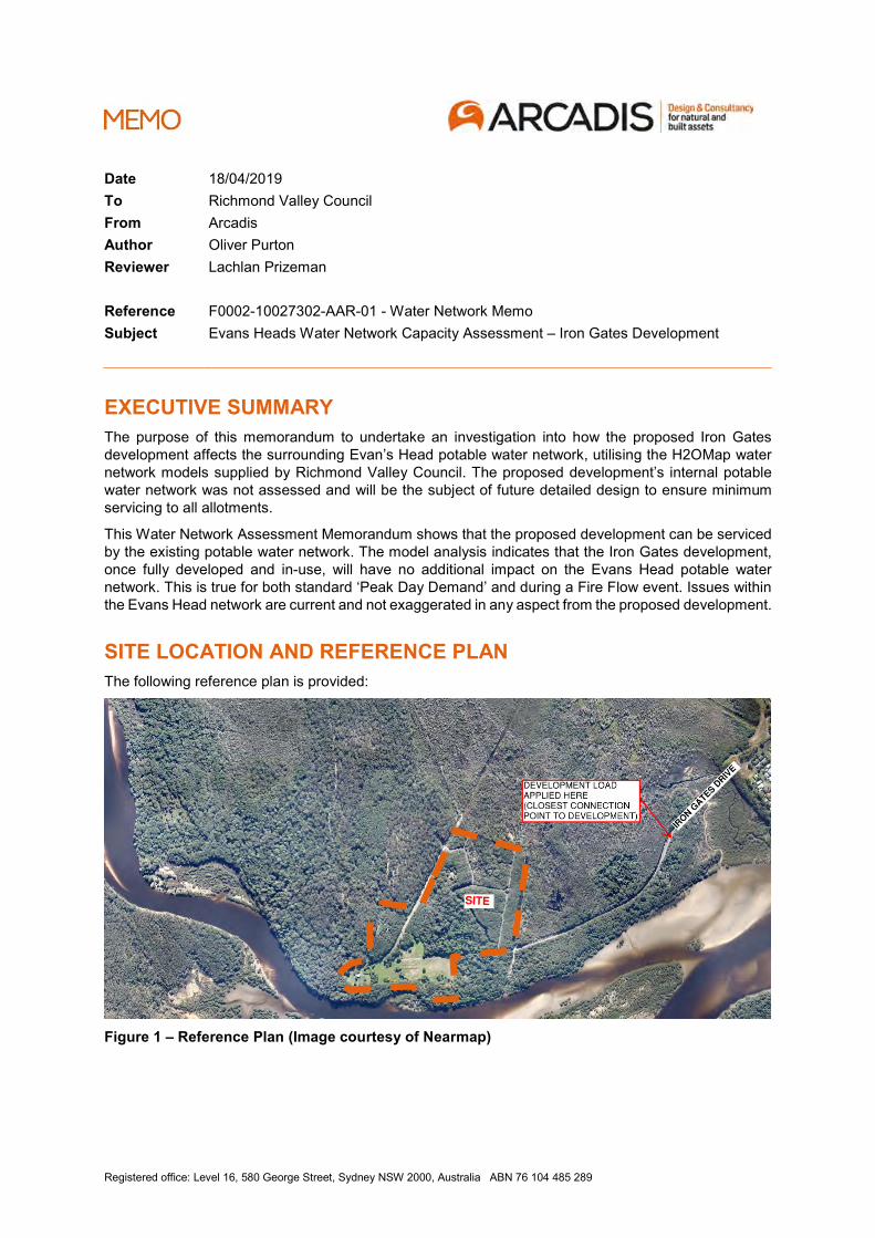
Registered office: Level 16, 580 George Street, Sydney NSW 2000, Australia ABN 76 104 485 289
Date 18/04/2019
To Richmond Valley Council
From Arcadis
Author Oliver Purton
Reviewer Lachlan Prizeman
Reference F0002-10027302-AAR-01 - Water Network Memo
Subject Evans Heads Water Network Capacity Assessment – Iron Gates Development
EXECUTIVE SUMMARY
The purpose of this memorandum to undertake an investigation into how the proposed Iron Gates
development affects the surrounding Evan’s Head potable water network, utilising the H2OMap water
network models supplied by Richmond Valley Council. The proposed development’s internal potable
water network was not assessed and will be the subject of future detailed design to ensure minimum
servicing to all allotments.
This Water Network Assessment Memorandum shows that the proposed development can be serviced
by the existing potable water network. The model analysis indicates that the Iron Gates development,
once fully developed and in-use, will have no additional impact on the Evans Head potable water
network. This is true for both standard ‘Peak Day Demand’ and during a Fire Flow event. Issues within
the Evans Head network are current and not exaggerated in any aspect from the proposed development.
SITE LOCATION AND REFERENCE PLAN
The following reference plan is provided:
Figure 1 – Reference Plan (Image courtesy of Nearmap)
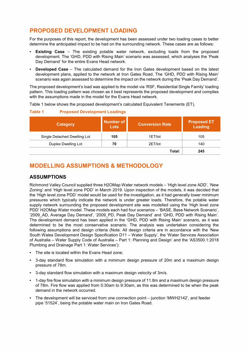
PROPOSED DEVELOPMENT LOADING
For the purposes of this report, the development has been assessed under two loading cases to better
determine the anticipated impact to be had on the surrounding network. These cases are as follows:
• Existing Case – The existing potable water network, excluding loads from the proposed
development. The ‘GHD, PDD with Rising Main’ scenario was assessed, which analyses the ‘Peak
Day Demand’ for the entire Evans Head network.
• Developed Case – The calculated demand for the Iron Gates development based on the latest
development plans, applied to the network at Iron Gates Road. The ‘GHD, PDD with Rising Main’
scenario was again assessed to determine the impact on the network during the ‘Peak Day Demand’.
The proposed development’s load was applied to the model via ‘RSF, Residential Single Family’ loading
pattern. This loading pattern was chosen as it best represents the proposed development and complies
with the assumptions made in the model for the Evans Head network.
Table 1 below shows the proposed development’s calculated Equivalent Tenements (ET).
Table 1 Proposed Development Loadings
Category Number of
Lots Conversion Rate
Proposed ET
Loading
Single Detached Dwelling Lot 105 1ET/lot 105
Duplex Dwelling Lot 70 2ET/lot 140
Total: 245
MODELLING ASSUMPTIONS & METHODOLOGY
ASSUMPTIONS
Richmond Valley Council supplied three H2OMap Water network models – ‘High level zone ADD’, ‘New
Zoning’ and ‘High level zone PDD’ in March 2019. Upon inspection of the models, it was decided that
the ‘High level zone PDD’ model would be used for the investigation, as it had generally lower minimum
pressures which typically indicate the network is under greater loads. Therefore, the potable water
supply network surrounding the proposed development site was modelled using the ‘High level zone
PDD’ H2OMap Water model. These models each had four scenarios – ‘BASE, Base Network Scenario’,
‘2009_AD, Average Day Demand’, ‘2009_PD, Peak Day Demand’ and ‘GHD, PDD with Rising Main’.
The development demand has been applied in the ‘GHD, PDD with Rising Main’ scenario, as it was
determined to be the most conservative scenario. The analysis was undertaken considering the
following assumptions and design criteria (Note: All design criteria are in accordance with the ‘New
South Wales Development Design Specification D11 – Water Supply’, the ‘Water Services Association
of Australia – Water Supply Code of Australia – Part 1: Planning and Design’ and the ‘AS3500.1:2018
Plumbing and Drainage Part 1: Water Services’):
• The site is located within the Evans Head zone;
• 3-day standard flow simulation with a minimum design pressure of 20m and a maximum design
pressure of 78m.
• 3-day standard flow simulation with a maximum design velocity of 3m/s.
• 1-day fire flow simulation with a minimum design pressure of 11.8m and a maximum design pressure
of 78m. Fire flow was applied from 5:30am to 9:30am, as this was determined to be when the peak
demand in the network occurred.
• The development will be serviced from one connection point – junction ‘MWH2142’, and feeder
pipe ‘51524’, being the potable water main on Iron Gates Road.
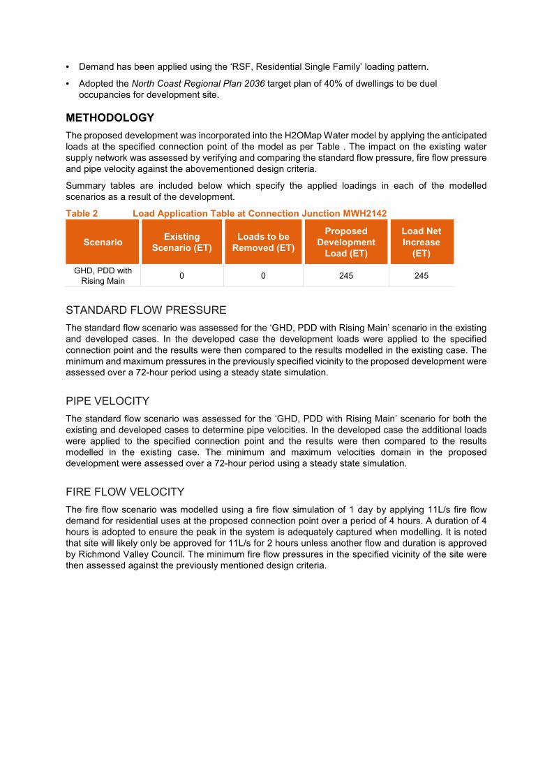
• Demand has been applied using the ‘RSF, Residential Single Family’ loading pattern.
• Adopted the North Coast Regional Plan 2036 target plan of 40% of dwellings to be duel
occupancies for development site.
METHODOLOGY
The proposed development was incorporated into the H2OMap Water model by applying the anticipated
loads at the specified connection point of the model as per Table . The impact on the existing water
supply network was assessed by verifying and comparing the standard flow pressure, fire flow pressure
and pipe velocity against the abovementioned design criteria.
Summary tables are included below which specify the applied loadings in each of the modelled
scenarios as a result of the development.
Table 2 Load Application Table at Connection Junction MWH2142
Scenario Existing
Scenario (ET)
Loads to be
Removed (ET)
Proposed
Development
Load (ET)
Load Net
Increase
(ET)
GHD, PDD with
Rising Main 0 0 245 245
STANDARD FLOW PRESSURE
The standard flow scenario was assessed for the ‘GHD, PDD with Rising Main’ scenario in the existing
and developed cases. In the developed case the development loads were applied to the specified
connection point and the results were then compared to the results modelled in the existing case. The
minimum and maximum pressures in the previously specified vicinity to the proposed development were
assessed over a 72-hour period using a steady state simulation.
PIPE VELOCITY
The standard flow scenario was assessed for the ‘GHD, PDD with Rising Main’ scenario for both the
existing and developed cases to determine pipe velocities. In the developed case the additional loads
were applied to the specified connection point and the results were then compared to the results
modelled in the existing case. The minimum and maximum velocities domain in the proposed
development were assessed over a 72-hour period using a steady state simulation.
FIRE FLOW VELOCITY
The fire flow scenario was modelled using a fire flow simulation of 1 day by applying 11L/s fire flow
demand for residential uses at the proposed connection point over a period of 4 hours. A duration of 4
hours is adopted to ensure the peak in the system is adequately captured when modelling. It is noted
that site will likely only be approved for 11L/s for 2 hours unless another flow and duration is approved
by Richmond Valley Council. The minimum fire flow pressures in the specified vicinity of the site were
then assessed against the previously mentioned design criteria.
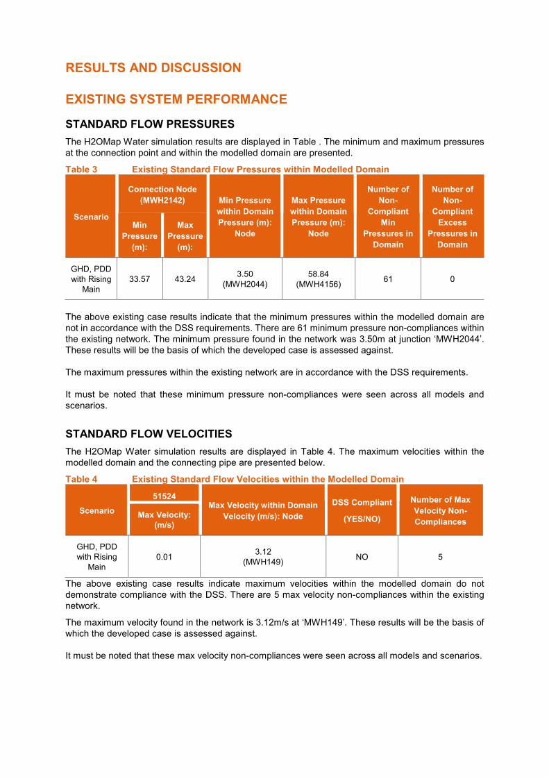
RESULTS AND DISCUSSION
EXISTING SYSTEM PERFORMANCE
STANDARD FLOW PRESSURES
The H2OMap Water simulation results are displayed in Table . The minimum and maximum pressures
at the connection point and within the modelled domain are presented.
Table 3 Existing Standard Flow Pressures within Modelled Domain
Scenario
Connection Node
(MWH2142) Min Pressure
within Domain
Pressure (m):
Node
Max Pressure
within Domain
Pressure (m):
Node
Number of
Non-
Compliant
Min
Pressures in
Domain
Number of
Non-
Compliant
Excess
Pressures in
Domain
Min
Pressure
(m):
Max
Pressure
(m):
GHD, PDD
with Rising
Main
33.57 43.24 3.50
(MWH2044)
58.84
(MWH4156) 61 0
The above existing case results indicate that the minimum pressures within the modelled domain are
not in accordance with the DSS requirements. There are 61 minimum pressure non-compliances within
the existing network. The minimum pressure found in the network was 3.50m at junction ‘MWH2044’.
These results will be the basis of which the developed case is assessed against.
The maximum pressures within the existing network are in accordance with the DSS requirements.
It must be noted that these minimum pressure non-compliances were seen across all models and
scenarios.
STANDARD FLOW VELOCITIES
The H2OMap Water simulation results are displayed in Table 4. The maximum velocities within the
modelled domain and the connecting pipe are presented below.
Table 4 Existing Standard Flow Velocities within the Modelled Domain
Scenario
51524 Max Velocity within Domain
Velocity (m/s): Node
DSS Compliant
(YES/NO)
Number of Max
Velocity Non-
Compliances Max Velocity:
(m/s)
GHD, PDD
with Rising
Main
0.01 3.12
(MWH149) NO 5
The above existing case results indicate maximum velocities within the modelled domain do not
demonstrate compliance with the DSS. There are 5 max velocity non-compliances within the existing
network.
The maximum velocity found in the network is 3.12m/s at ‘MWH149’. These results will be the basis of
which the developed case is assessed against.
It must be noted that these max velocity non-compliances were seen across all models and scenarios.
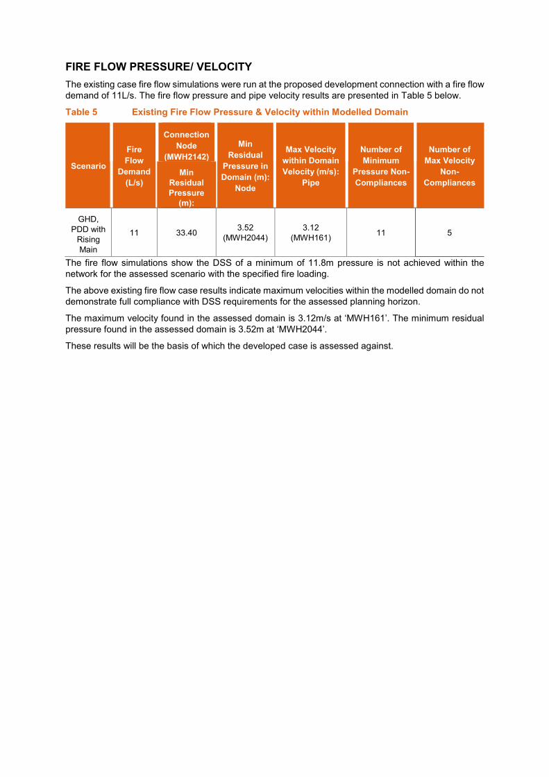
FIRE FLOW PRESSURE/ VELOCITY
The existing case fire flow simulations were run at the proposed development connection with a fire flow
demand of 11L/s. The fire flow pressure and pipe velocity results are presented in Table 5 below.
Table 5 Existing Fire Flow Pressure & Velocity within Modelled Domain
Scenario
Fire
Flow
Demand
(L/s)
Connection
Node
(MWH2142)
Min
Residual
Pressure in
Domain (m):
Node
Max Velocity
within Domain
Velocity (m/s):
Pipe
Number of
Minimum
Pressure Non-
Compliances
Number of
Max Velocity
Non-
Compliances
Min
Residual
Pressure
(m):
GHD,
PDD with
Rising
Main
11 33.40 3.52
(MWH2044)
3.12
(MWH161) 11 5
The fire flow simulations show the DSS of a minimum of 11.8m pressure is not achieved within the
network for the assessed scenario with the specified fire loading.
The above existing fire flow case results indicate maximum velocities within the modelled domain do not
demonstrate full compliance with DSS requirements for the assessed planning horizon.
The maximum velocity found in the assessed domain is 3.12m/s at ‘MWH161’. The minimum residual
pressure found in the assessed domain is 3.52m at ‘MWH2044’.
These results will be the basis of which the developed case is assessed against.
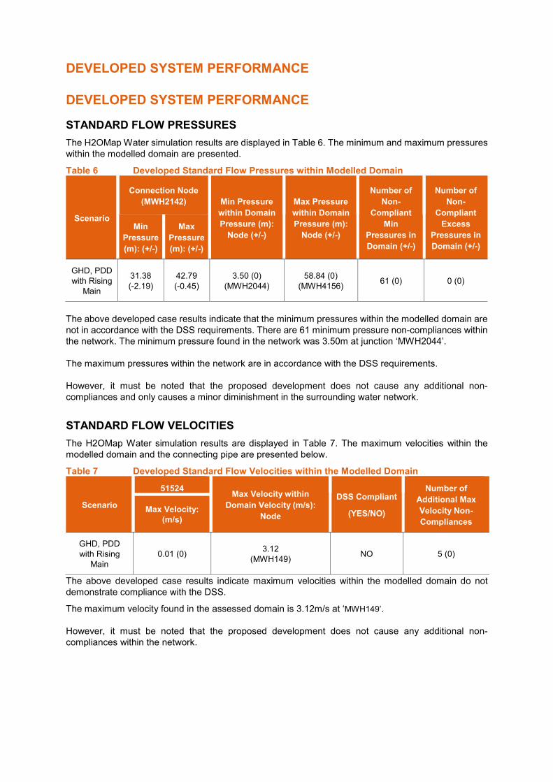
DEVELOPED SYSTEM PERFORMANCE
DEVELOPED SYSTEM PERFORMANCE
STANDARD FLOW PRESSURES
The H2OMap Water simulation results are displayed in Table 6. The minimum and maximum pressures
within the modelled domain are presented.
Table 6 Developed Standard Flow Pressures within Modelled Domain
Scenario
Connection Node
(MWH2142) Min Pressure
within Domain
Pressure (m):
Node (+/-)
Max Pressure
within Domain
Pressure (m):
Node (+/-)
Number of
Non-
Compliant
Min
Pressures in
Domain (+/-)
Number of
Non-
Compliant
Excess
Pressures in
Domain (+/-)
Min
Pressure
(m): (+/-)
Max
Pressure
(m): (+/-)
GHD, PDD
with Rising
Main
31.38
(-2.19)
42.79
(-0.45)
3.50 (0)
(MWH2044)
58.84 (0)
(MWH4156) 61 (0) 0 (0)
The above developed case results indicate that the minimum pressures within the modelled domain are
not in accordance with the DSS requirements. There are 61 minimum pressure non-compliances within
the network. The minimum pressure found in the network was 3.50m at junction ‘MWH2044’.
The maximum pressures within the network are in accordance with the DSS requirements.
However, it must be noted that the proposed development does not cause any additional non-
compliances and only causes a minor diminishment in the surrounding water network.
STANDARD FLOW VELOCITIES
The H2OMap Water simulation results are displayed in Table 7. The maximum velocities within the
modelled domain and the connecting pipe are presented below.
Table 7 Developed Standard Flow Velocities within the Modelled Domain
Scenario
51524 Max Velocity within
Domain Velocity (m/s):
Node
DSS Compliant
(YES/NO)
Number of
Additional Max
Velocity Non-
Compliances
Max Velocity:
(m/s)
GHD, PDD
with Rising
Main
0.01 (0) 3.12
(MWH149) NO 5 (0)
The above developed case results indicate maximum velocities within the modelled domain do not
demonstrate compliance with the DSS.
The maximum velocity found in the assessed domain is 3.12m/s at ‘MWH149’.
However, it must be noted that the proposed development does not cause any additional non-
compliances within the network.
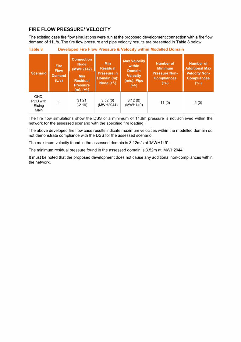
FIRE FLOW PRESSURE/ VELOCITY
The existing case fire flow simulations were run at the proposed development connection with a fire flow
demand of 11L/s. The fire flow pressure and pipe velocity results are presented in Table 8 below.
Table 8 Developed Fire Flow Pressure & Velocity within Modelled Domain
Scenario
Fire
Flow
Demand
(L/s)
Connection
Node
(MWH2142)
Min
Residual
Pressure in
Domain (m):
Node (+/-)
Max Velocity
within
Domain
Velocity
(m/s): Pipe
(+/-)
Number of
Minimum
Pressure Non-
Compliances
(+/-)
Number of
Additional Max
Velocity Non-
Compliances
(+/-)
Min
Residual
Pressure
(m): (+/-)
GHD,
PDD with
Rising
Main
11 31.21
(-2.19)
3.52 (0)
(MWH2044)
3.12 (0)
(MWH149) 11 (0) 5 (0)
The fire flow simulations show the DSS of a minimum of 11.8m pressure is not achieved within the
network for the assessed scenario with the specified fire loading.
The above developed fire flow case results indicate maximum velocities within the modelled domain do
not demonstrate compliance with the DSS for the assessed scenario.
The maximum velocity found in the assessed domain is 3.12m/s at ‘MWH149’.
The minimum residual pressure found in the assessed domain is 3.52m at ‘MWH2044’.
It must be noted that the proposed development does not cause any additional non-compliances within
the network.

CONCLUSION
This Water Network Assessment Memorandum shows that the proposed development can be serviced
by the existing potable water network.
Upon the inclusion of the development, the assessment resulted in the following conclusions:
• Standard Flow Pressure – Some minimum pressures for both the existing and developed case do not comply with the DSS requirements for the assessed scenario. The proposed development does not cause any additional minimum pressure non-compliances within the network, any non-compliances are current and existing according to the model. The maximum pressure for both the existing and developed case comply with the DSS requirements for the assessed scenario.
• Standard Flow Velocity – There are max velocity non-compliances in both the existing and developed scenario. However, the proposed development does not cause any additional non-compliances.
• Fire Flow – For both the existing and developed cases, the DSS minimum of 11.8m pressure was
not achieved for particular areas in the assessed scenario. There was multiple max velocity non-
compliance in both the existing and developed scenarios. However, the proposed development does
not cause any additional non-compliances in either low pressure or high velocity.
The above discussion and model analysis indicate that the Iron Gates development, once fully
developed and in-use, will have no additional impact on the Evans Head potable water network. This is
true for both standard ‘Peak Day Demand’ and during a Fire Flow event. Issues within the Evans Head
network are current and not exaggerated in any aspect from the proposed development.

40
APPENDIX H
SEWER NETWORK CAPACITY ASSESMENT
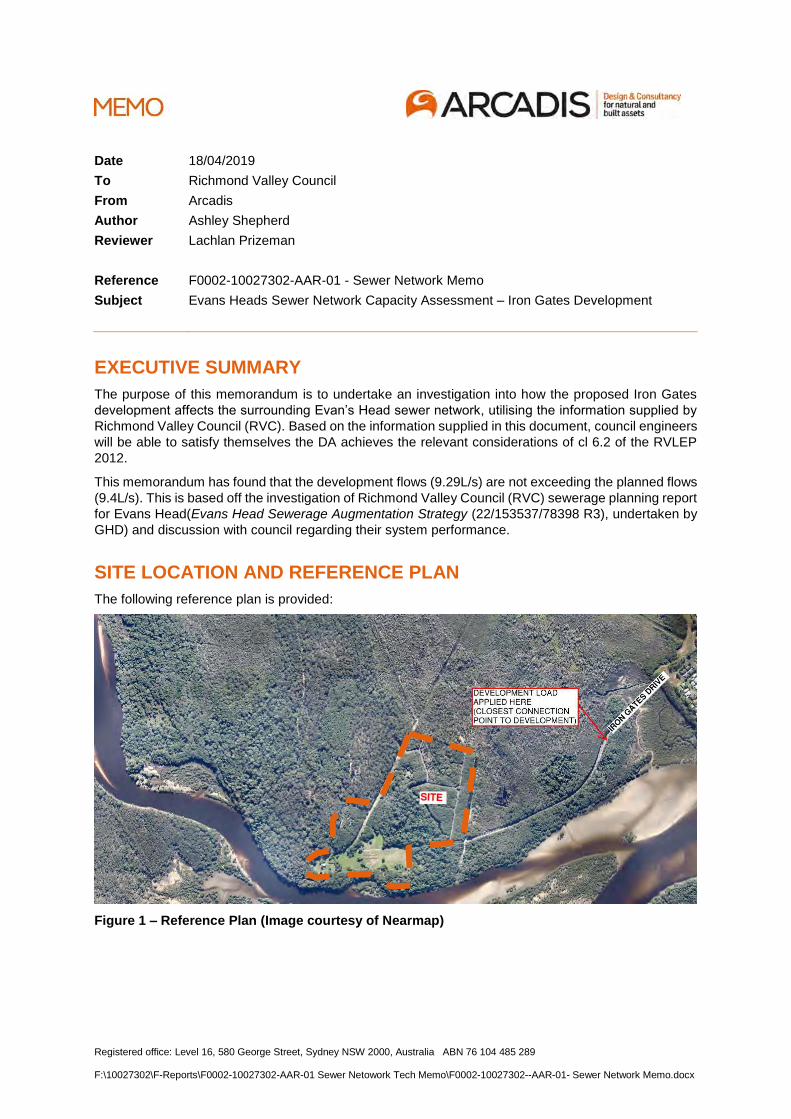
Registered office: Level 16, 580 George Street, Sydney NSW 2000, Australia ABN 76 104 485 289 F:\10027302\F-Reports\F0002-10027302-AAR-01 Sewer Netowork Tech Memo\F0002-10027302--AAR-01- Sewer Network Memo.docx
Date 18/04/2019
To Richmond Valley Council
From Arcadis
Author Ashley Shepherd
Reviewer Lachlan Prizeman
Reference F0002-10027302-AAR-01 - Sewer Network Memo
Subject Evans Heads Sewer Network Capacity Assessment – Iron Gates Development
EXECUTIVE SUMMARY
The purpose of this memorandum is to undertake an investigation into how the proposed Iron Gates
development affects the surrounding Evan’s Head sewer network, utilising the information supplied by
Richmond Valley Council (RVC). Based on the information supplied in this document, council engineers
will be able to satisfy themselves the DA achieves the relevant considerations of cl 6.2 of the RVLEP
2012.
This memorandum has found that the development flows (9.29L/s) are not exceeding the planned flows
(9.4L/s). This is based off the investigation of Richmond Valley Council (RVC) sewerage planning report
for Evans Head(Evans Head Sewerage Augmentation Strategy (22/153537/78398 R3), undertaken by
GHD) and discussion with council regarding their system performance.
SITE LOCATION AND REFERENCE PLAN
The following reference plan is provided:
Figure 1 – Reference Plan (Image courtesy of Nearmap)
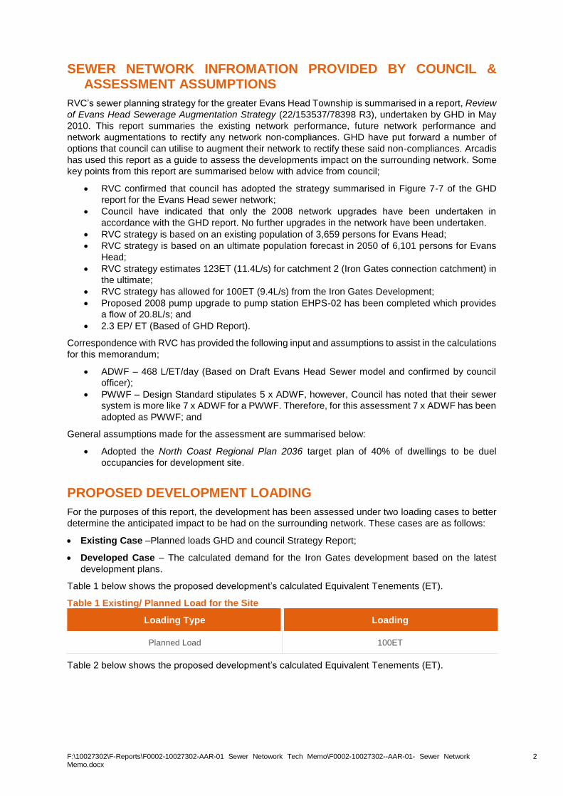
F:\10027302\F-Reports\F0002-10027302-AAR-01 Sewer Netowork Tech Memo\F0002-10027302--AAR-01- Sewer Network Memo.docx
2
SEWER NETWORK INFROMATION PROVIDED BY COUNCIL & ASSESSMENT ASSUMPTIONS
RVC’s sewer planning strategy for the greater Evans Head Township is summarised in a report, Review
of Evans Head Sewerage Augmentation Strategy (22/153537/78398 R3), undertaken by GHD in May
2010. This report summaries the existing network performance, future network performance and
network augmentations to rectify any network non-compliances. GHD have put forward a number of
options that council can utilise to augment their network to rectify these said non-compliances. Arcadis
has used this report as a guide to assess the developments impact on the surrounding network. Some
key points from this report are summarised below with advice from council;
• RVC confirmed that council has adopted the strategy summarised in Figure 7-7 of the GHD
report for the Evans Head sewer network;
• Council have indicated that only the 2008 network upgrades have been undertaken in
accordance with the GHD report. No further upgrades in the network have been undertaken.
• RVC strategy is based on an existing population of 3,659 persons for Evans Head;
• RVC strategy is based on an ultimate population forecast in 2050 of 6,101 persons for Evans
Head;
• RVC strategy estimates 123ET (11.4L/s) for catchment 2 (Iron Gates connection catchment) in
the ultimate;
• RVC strategy has allowed for 100ET (9.4L/s) from the Iron Gates Development;
• Proposed 2008 pump upgrade to pump station EHPS-02 has been completed which provides
a flow of 20.8L/s; and
• 2.3 EP/ ET (Based of GHD Report).
Correspondence with RVC has provided the following input and assumptions to assist in the calculations
for this memorandum;
• ADWF – 468 L/ET/day (Based on Draft Evans Head Sewer model and confirmed by council
officer);
• PWWF – Design Standard stipulates 5 x ADWF, however, Council has noted that their sewer
system is more like 7 x ADWF for a PWWF. Therefore, for this assessment 7 x ADWF has been
adopted as PWWF; and
General assumptions made for the assessment are summarised below:
• Adopted the North Coast Regional Plan 2036 target plan of 40% of dwellings to be duel
occupancies for development site.
PROPOSED DEVELOPMENT LOADING
For the purposes of this report, the development has been assessed under two loading cases to better
determine the anticipated impact to be had on the surrounding network. These cases are as follows:
• Existing Case –Planned loads GHD and council Strategy Report;
• Developed Case – The calculated demand for the Iron Gates development based on the latest
development plans.
Table 1 below shows the proposed development’s calculated Equivalent Tenements (ET).
Table 1 Existing/ Planned Load for the Site
Loading Type Loading
Planned Load 100ET
Table 2 below shows the proposed development’s calculated Equivalent Tenements (ET).
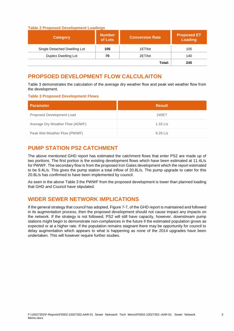
F:\10027302\F-Reports\F0002-10027302-AAR-01 Sewer Netowork Tech Memo\F0002-10027302--AAR-01- Sewer Network Memo.docx
3
Table 2 Proposed Development Loadings
Category Number
of Lots Conversion Rate
Proposed ET
Loading
Single Detached Dwelling Lot 105 1ET/lot 105
Duplex Dwelling Lot 70 2ET/lot 140
Total: 245
PROPSOED DEVELOPMENT FLOW CALCULAITON
Table 3 demonstrates the calculation of the average dry weather flow and peak wet weather flow from
the development.
Table 3 Proposed Development Flows
Parameter Result
Proposed Development Load 245ET
Average Dry Weather Flow (ADWF) 1.33 L/s
Peak Wet Weather Flow (PWWF) 9.29 L/s
PUMP STATION PS2 CATCHMENT
The above mentioned GHD report has estimated the catchment flows that enter PS2 are made up of
two portions. The first portion is the existing development flows which have been estimated at 11.4L/s
for PWWF. The secondary flow is from the proposed Iron Gates development which the report estimated
to be 9.4L/s. This gives the pump station a total inflow of 20.8L/s. The pump upgrade to cater for this
20.8L/s has confirmed to have been implemented by council.
As seen in the above Table 3 the PWWF from the proposed development is lower than planned loading
that GHD and Council have stipulated.
WIDER SEWER NETWORK IMPLICATIONS
If the general strategy that council has adopted, Figure 7-7, of the GHD report is maintained and followed
in its augmentation process, then the proposed development should not cause impact any impacts on
the network. If the strategy is not followed, PS2 will still have capacity, however, downstream pump
stations might begin to demonstrate non-compliances in the future if the estimated population grows as
expected or at a higher rate. If the population remains stagnant there may be opportunity for council to
delay augmentation which appears to what is happening as none of the 2014 upgrades have been
undertaken. This will however require further studies.

41
APPENDIX I
TRAFFIC REPORT
ttmgroup.com.au
TTM Consulting Pty Ltd ABN 65 010 868 621
P 07 5514 8000 E [email protected]
PO Box 930 Sanctuary Cove QLD 4212
17 July 2019
Our Ref: 19GCT0119
Council Reference: MCU/2019/127
Attention: Mr Graeme Ingles
Gold Coral Pty Ltd
PO Box 3441
Australia Fair Southport 4215
Dear Graeme,
RE: Iron Gates Development, Evans Heads – Residential Subdivision
TTM Consulting Pty Ltd (TTM) has been engaged, as requested by Gold Coral Pty Ltd, to respond to Section
16.13 and 18.3 of the Richmond Valley Council’s Information Request (ref: No.2015/0096, dated 2 February
2019).
TTM has undertaken a traffic study for the proposed 175 residential lot subdivision and prepared a traffic
engineering assessment to form part of the revised Iron Gates residential subdivision development
application in Evans Heads.
The aim of this assessment is to discuss the proposed access road capacity and impact on the local network.
Introduction
The site is located along Iron Gates Drive, located approximately 2km west of Evans Head NSW. The property
description of the development is Lot 163 DP 831052, Lots 276 and 277 DP 755624, Crown Road Reserve
between Lots 163 DP 831052 and Lot 276 DP 755724, Crown Foreshore Reserve and Iron Gates Drive, Evans
Head NSW.
The site is currently zoned for General Residential and Environmental Conservation uses according to the
Richmond Valley Local Environmental Pan 2012 and is currently provided access from Iron Gates Drive.
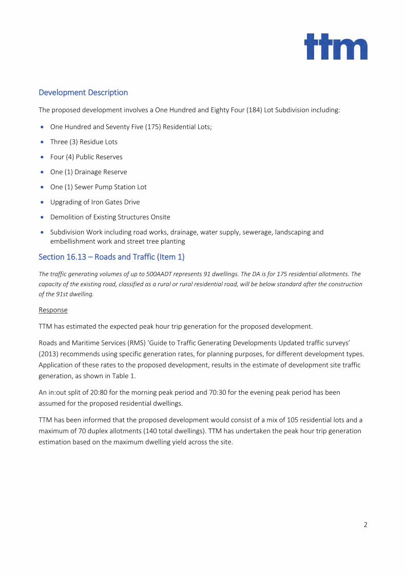
2
Development Description
The proposed development involves a One Hundred and Eighty Four (184) Lot Subdivision including:
• One Hundred and Seventy Five (175) Residential Lots;
• Three (3) Residue Lots
• Four (4) Public Reserves
• One (1) Drainage Reserve
• One (1) Sewer Pump Station Lot
• Upgrading of Iron Gates Drive
• Demolition of Existing Structures Onsite
• Subdivision Work including road works, drainage, water supply, sewerage, landscaping and embellishment work and street tree planting
Section 16.13 – Roads and Traffic (Item 1)
The traffic generating volumes of up to 500AADT represents 91 dwellings. The DA is for 175 residential allotments. The
capacity of the existing road, classified as a rural or rural residential road, will be below standard after the construction
of the 91st dwelling.
Response
TTM has estimated the expected peak hour trip generation for the proposed development.
Roads and Maritime Services (RMS) ‘Guide to Traffic Generating Developments Updated traffic surveys’
(2013) recommends using specific generation rates, for planning purposes, for different development types.
Application of these rates to the proposed development, results in the estimate of development site traffic
generation, as shown in Table 1.
An in:out split of 20:80 for the morning peak period and 70:30 for the evening peak period has been
assumed for the proposed residential dwellings.
TTM has been informed that the proposed development would consist of a mix of 105 residential lots and a
maximum of 70 duplex allotments (140 total dwellings). TTM has undertaken the peak hour trip generation
estimation based on the maximum dwelling yield across the site.
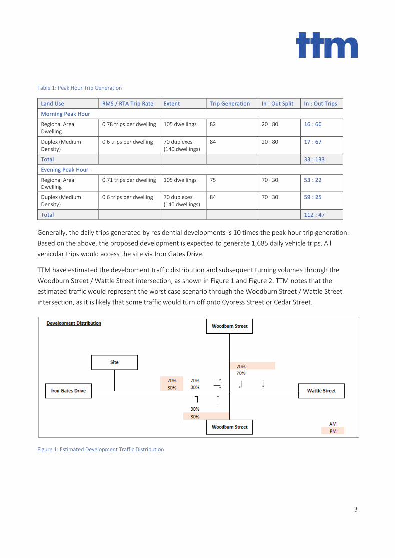
3
Table 1: Peak Hour Trip Generation
Land Use RMS / RTA Trip Rate Extent Trip Generation In : Out Split In : Out Trips
Morning Peak Hour
Regional Area Dwelling
0.78 trips per dwelling 105 dwellings 82 20 : 80 16 : 66
Duplex (Medium Density)
0.6 trips per dwelling 70 duplexes (140 dwellings)
84 20 : 80 17 : 67
Total 33 : 133
Evening Peak Hour
Regional Area Dwelling
0.71 trips per dwelling 105 dwellings 75 70 : 30 53 : 22
Duplex (Medium Density)
0.6 trips per dwelling 70 duplexes (140 dwellings)
84 70 : 30 59 : 25
Total 112 : 47
Generally, the daily trips generated by residential developments is 10 times the peak hour trip generation.
Based on the above, the proposed development is expected to generate 1,685 daily vehicle trips. All
vehicular trips would access the site via Iron Gates Drive.
TTM have estimated the development traffic distribution and subsequent turning volumes through the
Woodburn Street / Wattle Street intersection, as shown in Figure 1 and Figure 2. TTM notes that the
estimated traffic would represent the worst case scenario through the Woodburn Street / Wattle Street
intersection, as it is likely that some traffic would turn off onto Cypress Street or Cedar Street.
Figure 1: Estimated Development Traffic Distribution
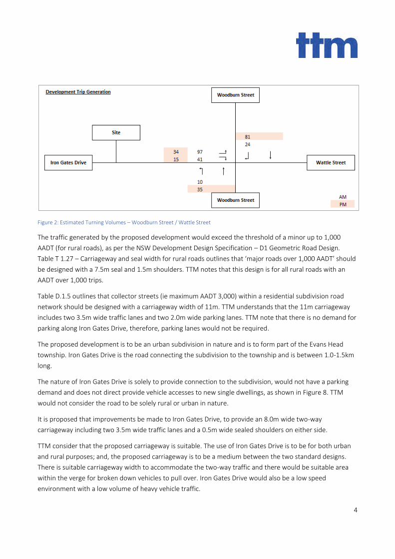
4
Figure 2: Estimated Turning Volumes – Woodburn Street / Wattle Street
The traffic generated by the proposed development would exceed the threshold of a minor up to 1,000
AADT (for rural roads), as per the NSW Development Design Specification – D1 Geometric Road Design.
Table T 1.27 – Carriageway and seal width for rural roads outlines that ‘major roads over 1,000 AADT’ should
be designed with a 7.5m seal and 1.5m shoulders. TTM notes that this design is for all rural roads with an
AADT over 1,000 trips.
Table D.1.5 outlines that collector streets (ie maximum AADT 3,000) within a residential subdivision road
network should be designed with a carriageway width of 11m. TTM understands that the 11m carriageway
includes two 3.5m wide traffic lanes and two 2.0m wide parking lanes. TTM note that there is no demand for
parking along Iron Gates Drive, therefore, parking lanes would not be required.
The proposed development is to be an urban subdivision in nature and is to form part of the Evans Head
township. Iron Gates Drive is the road connecting the subdivision to the township and is between 1.0-1.5km
long.
The nature of Iron Gates Drive is solely to provide connection to the subdivision, would not have a parking
demand and does not direct provide vehicle accesses to new single dwellings, as shown in Figure 8. TTM
would not consider the road to be solely rural or urban in nature.
It is proposed that improvements be made to Iron Gates Drive, to provide an 8.0m wide two-way
carriageway including two 3.5m wide traffic lanes and a 0.5m wide sealed shoulders on either side.
TTM consider that the proposed carriageway is suitable. The use of Iron Gates Drive is to be for both urban
and rural purposes; and, the proposed carriageway is to be a medium between the two standard designs.
There is suitable carriageway width to accommodate the two-way traffic and there would be suitable area
within the verge for broken down vehicles to pull over. Iron Gates Drive would also be a low speed
environment with a low volume of heavy vehicle traffic.
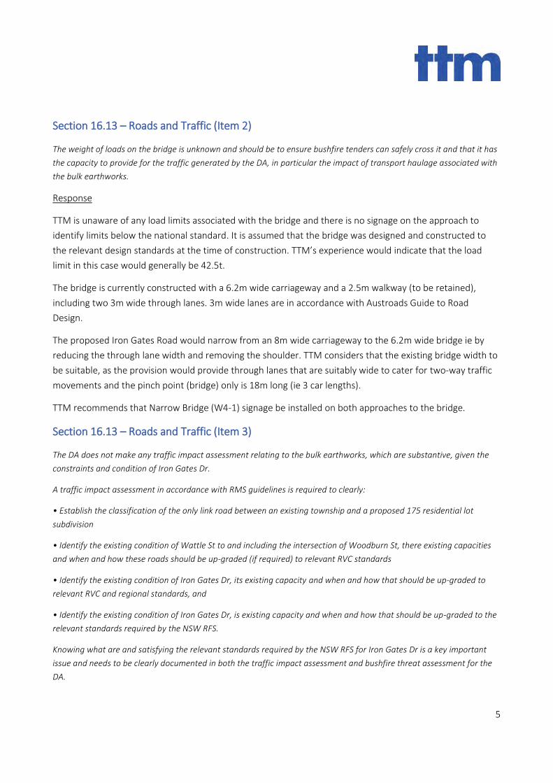
5
Section 16.13 – Roads and Traffic (Item 2)
The weight of loads on the bridge is unknown and should be to ensure bushfire tenders can safely cross it and that it has
the capacity to provide for the traffic generated by the DA, in particular the impact of transport haulage associated with
the bulk earthworks.
Response
TTM is unaware of any load limits associated with the bridge and there is no signage on the approach to
identify limits below the national standard. It is assumed that the bridge was designed and constructed to
the relevant design standards at the time of construction. TTM’s experience would indicate that the load
limit in this case would generally be 42.5t.
The bridge is currently constructed with a 6.2m wide carriageway and a 2.5m walkway (to be retained),
including two 3m wide through lanes. 3m wide lanes are in accordance with Austroads Guide to Road
Design.
The proposed Iron Gates Road would narrow from an 8m wide carriageway to the 6.2m wide bridge ie by
reducing the through lane width and removing the shoulder. TTM considers that the existing bridge width to
be suitable, as the provision would provide through lanes that are suitably wide to cater for two-way traffic
movements and the pinch point (bridge) only is 18m long (ie 3 car lengths).
TTM recommends that Narrow Bridge (W4-1) signage be installed on both approaches to the bridge.
Section 16.13 – Roads and Traffic (Item 3)
The DA does not make any traffic impact assessment relating to the bulk earthworks, which are substantive, given the
constraints and condition of Iron Gates Dr.
A traffic impact assessment in accordance with RMS guidelines is required to clearly:
• Establish the classification of the only link road between an existing township and a proposed 175 residential lot
subdivision
• Identify the existing condition of Wattle St to and including the intersection of Woodburn St, there existing capacities
and when and how these roads should be up-graded (if required) to relevant RVC standards
• Identify the existing condition of Iron Gates Dr, its existing capacity and when and how that should be up-graded to
relevant RVC and regional standards, and
• Identify the existing condition of Iron Gates Dr, is existing capacity and when and how that should be up-graded to the
relevant standards required by the NSW RFS.
Knowing what are and satisfying the relevant standards required by the NSW RFS for Iron Gates Dr is a key important
issue and needs to be clearly documented in both the traffic impact assessment and bushfire threat assessment for the
DA.
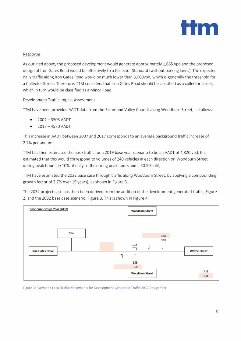
6
Response
As outlined above, the proposed development would generate approximately 1,685 vpd and the proposed
design of Iron Gates Road would be effectively to a Collector Standard (without parking lanes). The expected
daily traffic along Iron Gates Road would be much lower than 3,000vpd, which is generally the threshold for
a Collector Street. Therefore, TTM considers that Iron Gates Road should be classified as a collector street,
which in turn would be classified as a Minor Road.
Development Traffic Impact Assessment
TTM have been provided AADT data from the Richmond Valley Council along Woodburn Street, as follows:
• 2007 – 3505 AADT
• 2017 – 4570 AADT
This increase in AADT between 2007 and 2017 corresponds to an average background traffic increase of
2.7% per annum.
TTM has then estimated the base traffic for a 2019 base year scenario to be an AADT of 4,820 vpd. It is
estimated that this would correspond to volumes of 240 vehicles in each direction on Woodburn Street
during peak hours (ie 10% of daily traffic during peak hours and a 50:50 split).
TTM have estimated the 2032 base case through traffic along Woodburn Street, by applying a compounding
growth factor of 2.7% over 15 years), as shown in Figure 3.
The 2032 project case has then been derived from the addition of the development generated traffic, Figure
2, and the 2032 base case scenario, Figure 3. This is shown in Figure 4.
Figure 3: Estimated Local Traffic Movements for Development Generated Traffic 2032 Design Year
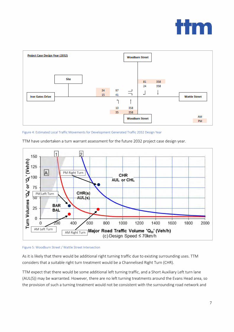
7
Figure 4: Estimated Local Traffic Movements for Development Generated Traffic 2032 Design Year
TTM have undertaken a turn warrant assessment for the future 2032 project case design year.
Figure 5: Woodburn Street / Wattle Street Intersection
As it is likely that there would be additional right turning traffic due to existing surrounding uses. TTM
considers that a suitable right turn treatment would be a Channelised Right Turn (CHR).
TTM expect that there would be some additional left turning traffic, and a Short Auxiliary Left turn lane
(AUL(S)) may be warranted. However, there are no left turning treatments around the Evans Head area, so
the provision of such a turning treatment would not be consistent with the surrounding road network and
AM Left Turn
PM Left Turn
AM Right Turn
PM Right Turn
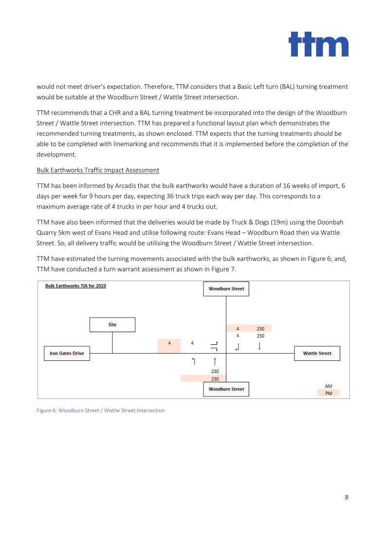
8
would not meet driver’s expectation. Therefore, TTM considers that a Basic Left turn (BAL) turning treatment
would be suitable at the Woodburn Street / Wattle Street intersection.
TTM recommends that a CHR and a BAL turning treatment be incorporated into the design of the Woodburn
Street / Wattle Street intersection. TTM has prepared a functional layout plan which demonstrates the
recommended turning treatments, as shown enclosed. TTM expects that the turning treatments should be
able to be completed with linemarking and recommends that it is implemented before the completion of the
development.
Bulk Earthworks Traffic Impact Assessment
TTM has been informed by Arcadis that the bulk earthworks would have a duration of 16 weeks of import, 6
days per week for 9 hours per day, expecting 36 truck trips each way per day. This corresponds to a
maximum average rate of 4 trucks in per hour and 4 trucks out.
TTM have also been informed that the deliveries would be made by Truck & Dogs (19m) using the Doonbah
Quarry 5km west of Evans Head and utilise following route: Evans Head – Woodburn Road then via Wattle
Street. So, all delivery traffic would be utilising the Woodburn Street / Wattle Street intersection.
TTM have estimated the turning movements associated with the bulk earthworks, as shown in Figure 6; and,
TTM have conducted a turn warrant assessment as shown in Figure 7.
Figure 6: Woodburn Street / Wattle Street Intersection
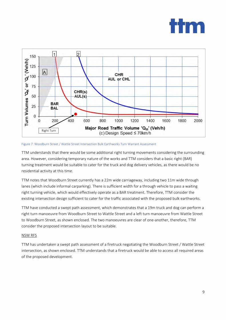
9
Figure 7: Woodburn Street / Wattle Street Intersection Bulk Earthworks Turn Warrant Assessment
TTM understands that there would be some additional right turning movements considering the surrounding
area. However, considering temporary nature of the works and TTM considers that a basic right (BAR)
turning treatment would be suitable to cater for the truck and dog delivery vehicles, as there would be no
residential activity at this time.
TTM notes that Woodburn Street currently has a 22m wide carriageway, including two 11m wide through
lanes (which include informal carparking). There is sufficient width for a through vehicle to pass a waiting
right turning vehicle, which would effectively operate as a BAR treatment. Therefore, TTM consider the
existing intersection design sufficient to cater for the traffic associated with the proposed bulk earthworks.
TTM have conducted a swept path assessment, which demonstrates that a 19m truck and dog can perform a
right turn manoeuvre from Woodburn Street to Wattle Street and a left turn manoeuvre from Wattle Street
to Woodburn Street, as shown enclosed. The two manoeuvres are clear of one-another, therefore, TTM
consider the proposed intersection layout to be suitable.
NSW RFS
TTM has undertaken a swept path assessment of a firetruck negotiating the Woodburn Street / Wattle Street
intersection, as shown enclosed. TTM understands that a firetruck would be able to access all required areas
of the proposed development.
Right Turn
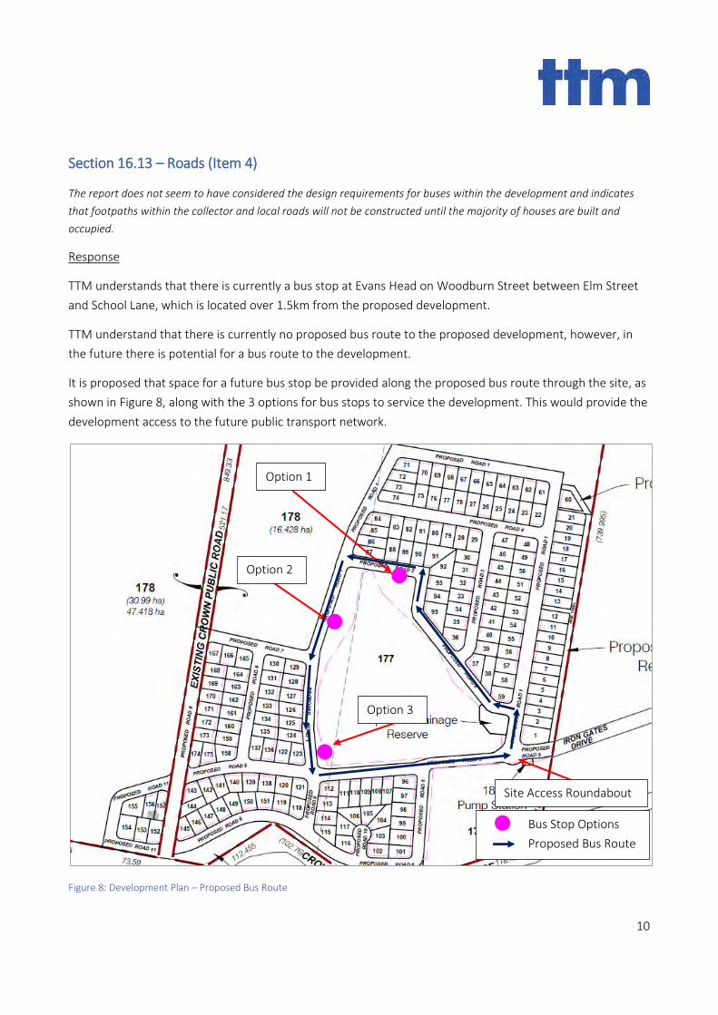
10
Section 16.13 – Roads (Item 4)
The report does not seem to have considered the design requirements for buses within the development and indicates
that footpaths within the collector and local roads will not be constructed until the majority of houses are built and
occupied.
Response
TTM understands that there is currently a bus stop at Evans Head on Woodburn Street between Elm Street
and School Lane, which is located over 1.5km from the proposed development.
TTM understand that there is currently no proposed bus route to the proposed development, however, in
the future there is potential for a bus route to the development.
It is proposed that space for a future bus stop be provided along the proposed bus route through the site, as
shown in Figure 8, along with the 3 options for bus stops to service the development. This would provide the
development access to the future public transport network.
Figure 8: Development Plan – Proposed Bus Route
Bus Stop Options
Proposed Bus Route
Option 1
Option 2
Option 3
Site Access Roundabout
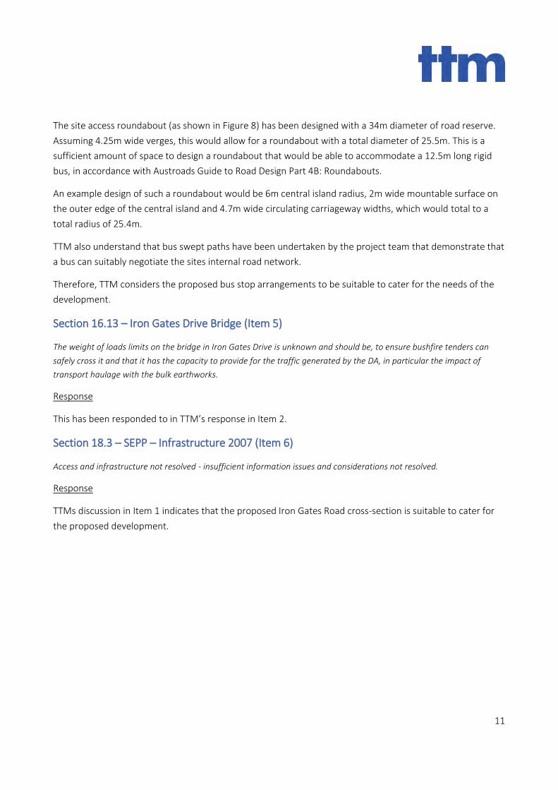
11
The site access roundabout (as shown in Figure 8) has been designed with a 34m diameter of road reserve.
Assuming 4.25m wide verges, this would allow for a roundabout with a total diameter of 25.5m. This is a
sufficient amount of space to design a roundabout that would be able to accommodate a 12.5m long rigid
bus, in accordance with Austroads Guide to Road Design Part 4B: Roundabouts.
An example design of such a roundabout would be 6m central island radius, 2m wide mountable surface on
the outer edge of the central island and 4.7m wide circulating carriageway widths, which would total to a
total radius of 25.4m.
TTM also understand that bus swept paths have been undertaken by the project team that demonstrate that
a bus can suitably negotiate the sites internal road network.
Therefore, TTM considers the proposed bus stop arrangements to be suitable to cater for the needs of the
development.
Section 16.13 – Iron Gates Drive Bridge (Item 5)
The weight of loads limits on the bridge in Iron Gates Drive is unknown and should be, to ensure bushfire tenders can
safely cross it and that it has the capacity to provide for the traffic generated by the DA, in particular the impact of
transport haulage with the bulk earthworks.
Response
This has been responded to in TTM’s response in Item 2.
Section 18.3 – SEPP – Infrastructure 2007 (Item 6)
Access and infrastructure not resolved - insufficient information issues and considerations not resolved.
Response
TTMs discussion in Item 1 indicates that the proposed Iron Gates Road cross-section is suitable to cater for
the proposed development.
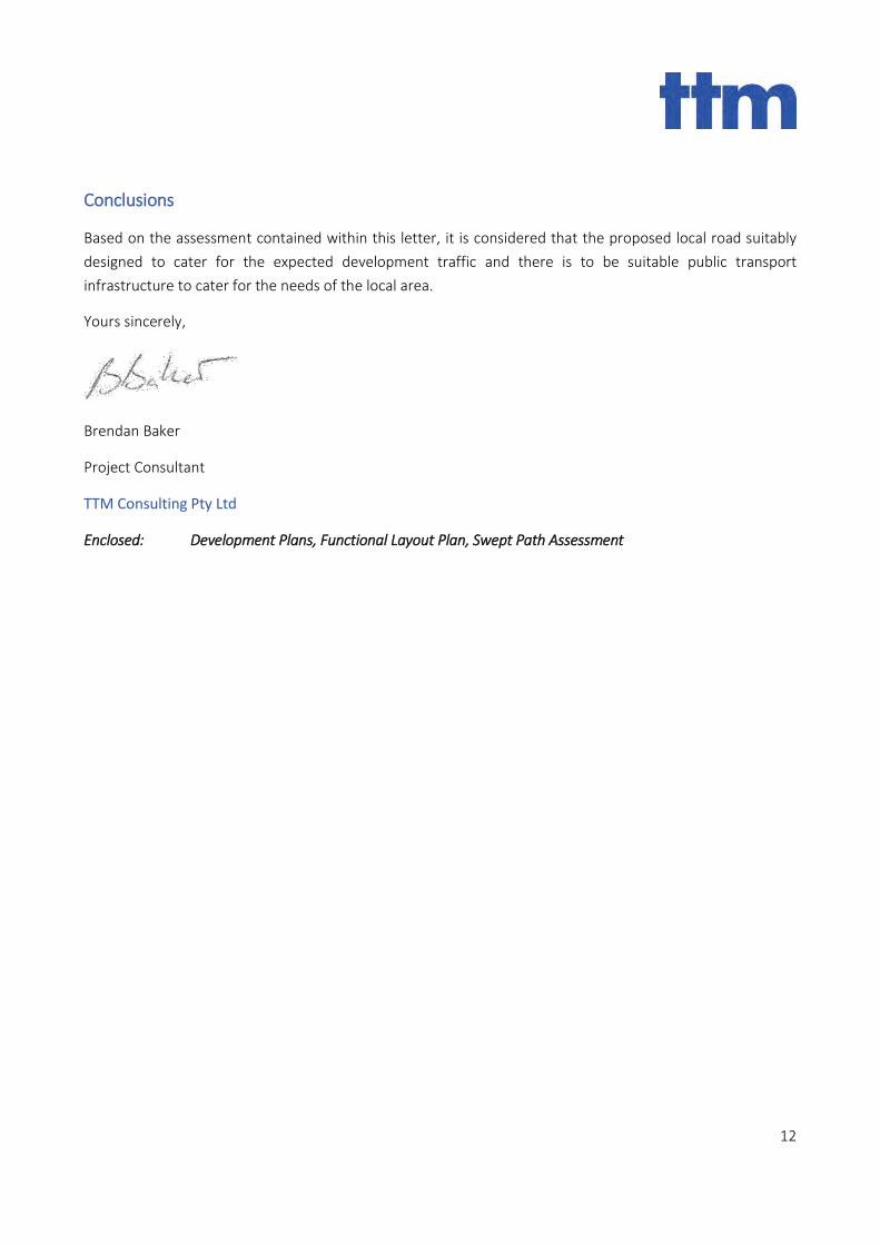
12
Conclusions
Based on the assessment contained within this letter, it is considered that the proposed local road suitably
designed to cater for the expected development traffic and there is to be suitable public transport
infrastructure to cater for the needs of the local area.
Yours sincerely,
Brendan Baker
Project Consultant
TTM Consulting Pty Ltd
Enclosed: Development Plans, Functional Layout Plan, Swept Path Assessment

PROPOSED ROAD 2
FIR
E TR
AIL
PRO
POSE
DRO
AD 1
274.
715
603.
15
402.3420.115
503.32
849.
3352
1.17
29.20594.26
65.2
59.92
66.58
26.38
9.65
5 102.35
48.425
112.455(102.76)
53.915 128.345
118.4973.59
121.
867
(739
.995
)
21
156
157
163
161
164
160
162
33
130
49
60
4
5
6
7
8
9
91
17
13
18
50
86
93
165
166
134
131
128
127
132
126
135
125
133
110
107108
109
111
106
105
114
113
124
2
3
51
38
10
12
11
14
15
16
19
20
48
52
59
56
40
55
54
41
53
42
43
44
45
46
47
83
82
85
81
80
92
79
28
29
36
35
34
32
31
30
84
22
23
24
25
26
27
78
77
76
75
73
72
39
57
58
1
37
153
152
88
90
89
94
95
129
159
121
175
158
136
122
137
123
112
97
101
100
99
98
96
74
87
167
174
173
172
171
170
169
168
143
102
115
104
116
103
117
70
69
68
67
66
65
64
63
62
71
61
144
141 120
139140
142
149
138
119
148
147
150
118
151
146
145
155
154
PROPOSED ROAD 4
PROPOSED ROAD 1
PRO
POSE
DR
OA
D 1
PRO
POSE
DR
OA
D 3
PROP
OSED
ROAD
1
PRO
POSE
DR
OA
D 1
PROPOSEDROAD 2
PROPOSED ROAD 7
PRO
POSE
DR
OA
D 8
PRO
POSE
DR
OA
D 6
PRO
POSED
RO
AD
1
PROPOSED ROAD 5
PROPOSED ROAD 11
PROPOSED ROAD 5PR
OPO
SED
RO
AD
6
PROPOSEDROAD 5
PRO
POSE
DR
OA
D 1
0
PROPOSED ROAD 6
PRO
POSE
DR
OA
D 9
PROPOSED ROAD 6
PROPOSED ROAD 11
IRON GATES
DRIVE
IRON GATES
DRIVE
WATTLE ST
EXIS
TIN
G C
RO
WN
PU
BLI
C R
OA
D
CROWNFORESHORE
RESERVE
SCALE 1:4000 @ A1
40m 0 80 200m
SHEET 1 OF 2
©LANDPARTNERS 2019
REV
APPROVED
NOTE: ALL DIMENSIONS AND AREAS ON THIS PLAN ARE SUBJECT TO SURVEY AND REQUIREMENTS FOR LODGEMENT OF SURVEY PLANS IN THE NSW LAND REGISTRY SERVICES
PLAN NUMBER
DATE
DRAWN
CHECKED
COMPUTER FILE
CONTOUR INTERVAL
LEVEL ORIGIN
LEVEL DATUM
DATE
DATE
ADDITIONAL NOTES
SCALE BAR
PROJECT
LOCAL AUTHORITY
CLIENT
NOTES
BRJD6396.100-015
-
BRJD6396-100-33-16
CGW
-
AHD
GOLDCORAL
PTY LTD
(i) This plan was prepared for the purpose and exclusive useof THE INGLES GROUP to accompany an application toRICHMOND VALLEY for approval to reconfigure the landdescribed in this plan and is not to be used for any otherpurpose or by any other person or corporation.LandPartners Pty Ltd accepts no responsibility for any loss ordamage suffered howsoever arising to any person orcorporation who may use or rely on this plan in contraventionof the terms of this clause or clauses (ii) or (iii) hereof.
(ii) The dimensions, areas, number of lots, size and location ofimprovements & flood information (if shown) are approximateonly and may vary.
(iii) This plan may not be copied unless these notes areincluded.
RICHMOND VALLEY
M CG
W
Brisbane Office
Level 1 - CDOP6
18 Little Cribb Street,
Milton Qld 4064
PO Box 1399
Milton Qld 4064
p: (07) 3842 1000
f: (07) 3842 1001
w: www.landpartners.com.au
bsi.
ISO 9001: FS 535063
ISO9001QualityManagement
SITE BOUNDARY
PROPOSED EASEMENT
LEGEND:
27/06/2019
27/06/2019
27/06/2019
CMJ
CGW
Lot Table Lot Table Lot Table
180Proposed Public
Reserve
178
(30.99 ha)47.418 ha
178
(16.428 ha)
176
179Proposed Public
Reserve
181Proposed Public
Reserve
182Proposed Public
Reserve
177
165
DP755624
165
DP755624
545
DP48550
544
DP48550
BLU
E POO
L RO
AD
547
DP48550
408
DP755624
408
DP755624
7016
DP1112989
VILLAGE OF
EVANS HEAD
7017
DP1112984
5
4
6
DP4
8550
MANGROVE ST
183Proposed Drainage
Reserve
EVANS RIVER
EVANS
R
IVER
PROPOSED SUBDIVISION OFLOTS 276 & 277 ON DP755624,
LOT 163 ON DP831052, CROWN PUBLICROAD RESERVE (BETWEEN LOT 163
DP831052 AND LOT 276 DP755624) ANDCROWN FORESHORE RESERVE(ADJACENT TO EVANS RIVER)
Resumed land vested in feesimple in the Minister for Public
Works as per Government Gazettedated 11 May 1894
164
DP831052
TOTAL
LOTS TOTAL AREA
72.309ha
Residue Lots (3)
Residential Lots (175)
Public Reserves (4)
54.463ha
0.8366ha
16.884ha
Drainage Reserve (1) 0.1124ha
Pump station lot (1) 0.0127ha
184Pump Station
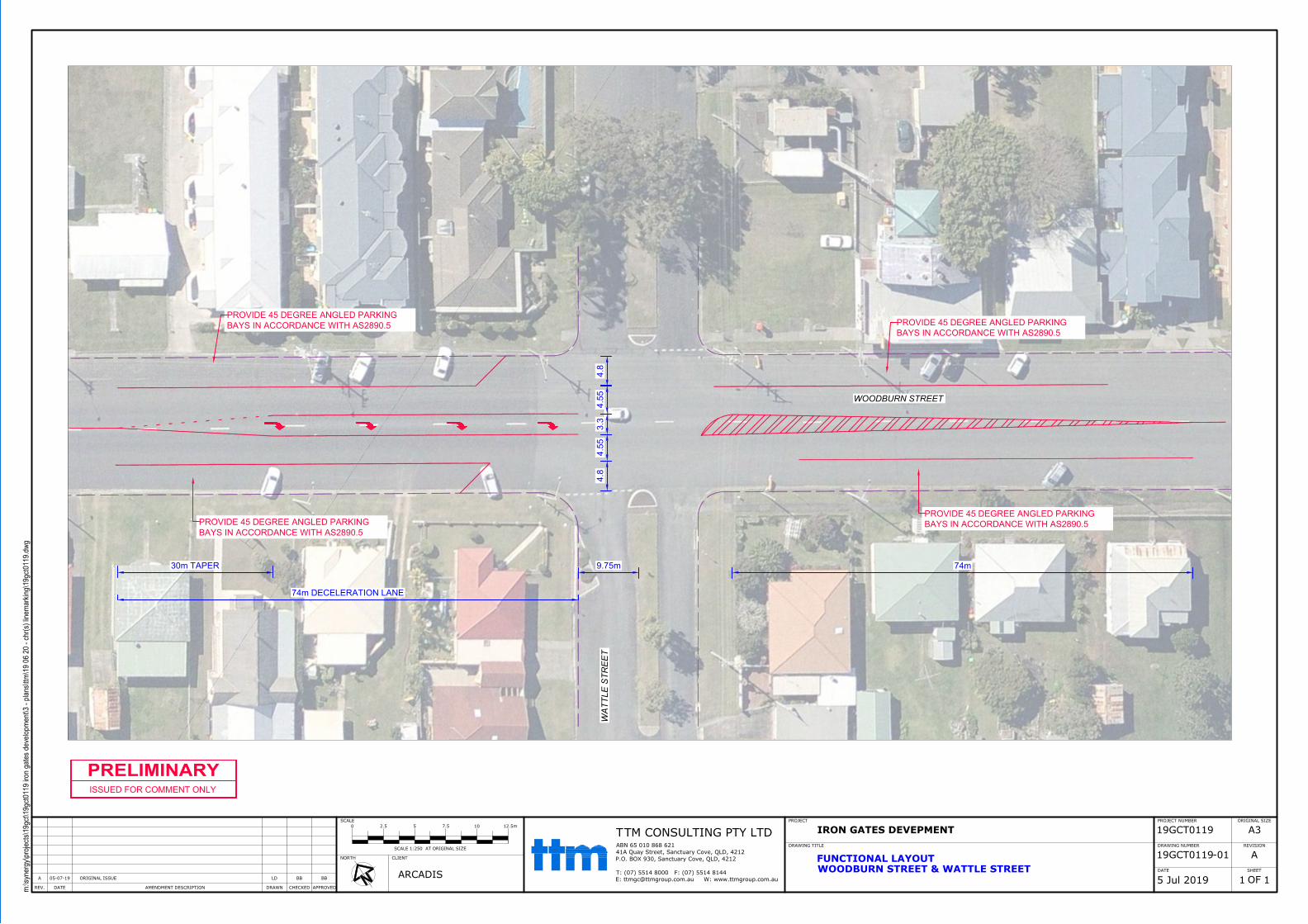
AMENDMENT DESCRIPTIONREV.
ORIGINAL ISSUE
DRAWN CHECKED APPROVEDDATE
PROJECT
DRAWING TITLE
IRON GATES DEVEPMENT
FUNCTIONAL LAYOUTWOODBURN STREET & WATTLE STREET
NORTH
SCALE PROJECT NUMBER
19GCT0119DRAWING NUMBER
19GCT0119DATE
REVISION
ORIGINAL SIZE
SHEET
OF
CLIENT
ARCADIS
0 2.5 10 12.5m7.55
SCALE 1:250 AT ORIGINAL SIZE
5 Jul 201905-07-19
A
A BBLD BB
-01
1 1
A3
m:\syn
erg
y\p
ro
je
cts\1
9g
ct\1
9g
ct0
11
9 iro
n g
ate
s d
eve
lo
pm
en
t\3
- p
la
ns\ttm
\1
9 0
6 2
0 - ch
r(s) lin
em
arkin
g\1
9g
ct0
11
9.d
wg
TM CONSULTING PTY LTDABN 65 010 868 62141A Quay Street, Sanctuary Cove, QLD, 4212P.O. BOX 930, Sanctuary Cove, QLD, 4212
T: (07) 5514 8000 F: (07) 5514 8144E: [email protected] W: www.ttmgroup.com.au
T
30m TAPER 9.75m 74m
74m DECELERATION LANE
WOODBURN STREET
WA
TT
LE
S
TR
EE
T
PRELIMINARY
ISSUED FOR COMMENT ONLY
4.5
53
.3
4.5
5
PROVIDE 45 DEGREE ANGLED PARKING
BAYS IN ACCORDANCE WITH AS2890.5
PROVIDE 45 DEGREE ANGLED PARKING
BAYS IN ACCORDANCE WITH AS2890.5
PROVIDE 45 DEGREE ANGLED PARKING
BAYS IN ACCORDANCE WITH AS2890.5
PROVIDE 45 DEGREE ANGLED PARKING
BAYS IN ACCORDANCE WITH AS2890.5
4.8
4.8
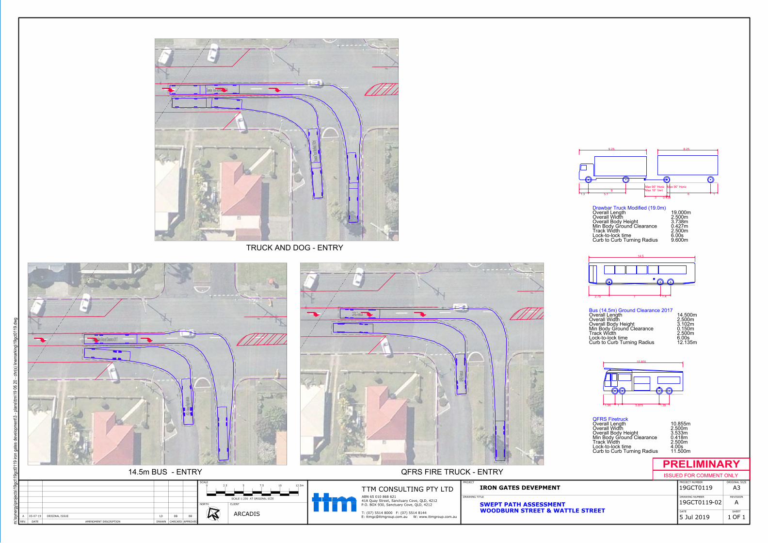
Drawbar Truck Modified (19.0m)
Draw
bar T
ruck M
odified (19.0m
)
QFRS Firetruck
QF
RS
F
iretruck
Bus (14.5m) Ground Clearance 2017
HR
V - H
eavy R
igid V
ehicle
AMENDMENT DESCRIPTIONREV.
ORIGINAL ISSUE
DRAWN CHECKED APPROVEDDATE
PROJECT
DRAWING TITLE
IRON GATES DEVEPMENT
SWEPT PATH ASSESSMENTWOODBURN STREET & WATTLE STREET
NORTH
SCALE PROJECT NUMBER
19GCT0119DRAWING NUMBER
19GCT0119DATE
REVISION
ORIGINAL SIZE
SHEET
OF
CLIENT
ARCADIS
0 2.5 10 12.5m7.55
SCALE 1:250 AT ORIGINAL SIZE
5 Jul 201905-07-19
A
A BBLD BB
-02
1 1
A3
m:\syn
erg
y\p
ro
je
cts\1
9g
ct\1
9g
ct0
11
9 iro
n g
ate
s d
eve
lo
pm
en
t\3
- p
la
ns\ttm
\1
9 0
6 2
0 - ch
r(s) lin
em
arkin
g\1
9g
ct0
11
9.d
wg
TM CONSULTING PTY LTDABN 65 010 868 62141A Quay Street, Sanctuary Cove, QLD, 4212P.O. BOX 930, Sanctuary Cove, QLD, 4212
T: (07) 5514 8000 F: (07) 5514 8144E: [email protected] W: www.ttmgroup.com.au
T
TRUCK AND DOG - ENTRY
QFRS FIRE TRUCK - ENTRY14.5m BUS - ENTRY
PRELIMINARY
ISSUED FOR COMMENT ONLY
14.5
2.75 7 1.4
Bus (14.5m) Ground Clearance 2017
Overall Length 14.500m
Overall Width 2.500m
Overall Body Height 3.102m
Min Body Ground Clearance 0.150m
Track Width 2.500m
Lock-to-lock time 6.00s
Curb to Curb Turning Radius 12.135m
8.259.25
Max 90° Horiz
6 1
Max 90° Horiz
Max 10° Vert
3 0.438
9
1.3 5.1
Drawbar Truck Modified (19.0m)
Overall Length 19.000m
Overall Width 2.500m
Overall Body Height 3.738m
Min Body Ground Clearance 0.427m
Track Width 2.500m
Lock-to-lock time 6.00s
Curb to Curb Turning Radius 9.600m
10.855
1.56 1 5.075 1.35
QFRS Firetruck
Overall Length 10.855m
Overall Width 2.500m
Overall Body Height 3.533m
Min Body Ground Clearance 0.418m
Track Width 2.500m
Lock-to-lock time 4.00s
Curb to Curb Turning Radius 11.500m