Embed Size (px)
Citation preview
GEOTECHNICAL ENGINEERING REPORT Proposed Bay View Wetlands Culvert
100 South Marina Drive
Milwaukee, Wisconsin
GESTRA Project No.: 17059-10
March 21, 2017
Prepared For:
AECOM
1555 Rivercenter Drive, Suite 214
Milwaukee, WI 53212
Geotechnical Engineering Report
Proposed Bay View Wetlands Culvert 100 South Marina Drive Milwaukee, Wisconsin
GESTRA Project No.: 17059-10
March 21, 2017
Prepared for:
AECOM 1555 Rivercenter Drive, Suite 214
Milwaukee, WI 53212
Report Prepared by:
GESTRA Engineering, Inc. 191 W. Edgerton Avenue
Milwaukee, WI 53207 (414) 933-7444
Proposed Bay View Wetlands Culvert, Milwaukee, WI March 21, 2017
GESTRA Engineering, Inc. Page 1 17059-10
TABLE OF CONTENTS 1.0 INTRODUCTION ......................................................................................................................2
1.1 Project Information ....................................................................................................................... 2
2.0 SCOPE OF WORK ....................................................................................................................2
3.0 EXPLORATION RESULTS .........................................................................................................2
3.1 Field Exploration and Laboratory Procedures .............................................................................. 2
3.2 Subsurface Soil Profile.................................................................................................................. 3
3.4 Groundwater Observations ........................................................................................................... 4
4.0 ANALYSIS AND RECOMMENDATIONS ......................................................................................4
4.1 Driven Pile Foundations................................................................................................................ 4
4.1.1 Maximum Factored Axial Compression Resistance ................................................................. 5
4.1.2 Maximum Geotechnical Resistance of Driven Piles ................................................................. 5
4.1.3 Maximum Driving Resistance (Drivability) ............................................................................. 6
4.1.4 Downdrag Force on driven Pile Foundation ............................................................................. 7
4.1.5 Pile Spacing .............................................................................................................................. 7
4.1.6 Lateral Squeeze Potential .......................................................................................................... 7
4.1.7 Estimated Settlement................................................................................................................. 7
4.2 Construction Consideration........................................................................................................... 7
4.2.1 Excavation Safety ..................................................................................................................... 7
4.2.2 Construction Dewatering .......................................................................................................... 8
4.2.3 Temporary Soil Retention System ............................................................................................ 8
4.2.4 Limitations ................................................................................................................................ 8
APPENDIX I BOREHOLE LAYOUT PLAN, TEST BORING LOGS, AND NOMENCLATURE
APPENDIX II LABORATORY TEST RESULTS
© GESTRA Engineering, Inc. 2017
Proposed Bay View Wetlands Culvert, Milwaukee, WI March 21, 2017
GESTRA Engineering, Inc. Page 2 17059-10
Geotechnical Engineering Report Proposed Bay View Wetlands Culvert
Milwaukee, Wisconsin
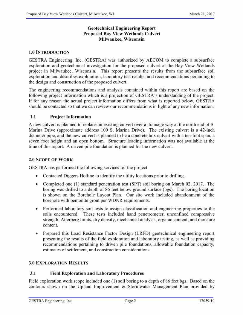
1.0 INTRODUCTION GESTRA Engineering, Inc. (GESTRA) was authorized by AECOM to complete a subsurface exploration and geotechnical investigation for the proposed culvert at the Bay View Wetlands project in Milwaukee, Wisconsin. This report presents the results from the subsurface soil exploration and describes exploration, laboratory test results, and recommendations pertaining to the design and construction of the proposed culvert.
The engineering recommendations and analysis contained within this report are based on the following project information which is a projection of GESTRA’s understanding of the project. If for any reason the actual project information differs from what is reported below, GESTRA should be contacted so that we can review our recommendations in light of any new information.
1.1 Project Information A new culvert is planned to replace an existing culvert over a drainage way at the north end of S. Marina Drive (approximate address 100 S. Marina Drive). The existing culvert is a 42-inch diameter pipe, and the new culvert is planned to be a concrete box culvert with a ten-foot span, a seven foot height and an open bottom. Structure loading information was not available at the time of this report. A driven pile foundation is planned for the new culvert.
2.0 SCOPE OF WORK GESTRA has performed the following services for the project:
Contacted Diggers Hotline to identify the utility locations prior to drilling.
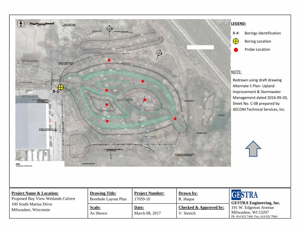
Completed one (1) standard penetration test (SPT) soil boring on March 02, 2017. The boring was drilled to a depth of 86 feet below ground surface (bgs). The boring location is shown on the Borehole Layout Plan. Our site work included abandonment of the borehole with bentonite grout per WDNR requirements.
Performed laboratory soil tests to assign classification and engineering properties to the soils encountered. These tests included hand penetrometer, unconfined compressive strength, Atterberg limits, dry density, mechanical analysis, organic content, and moisture content.
Prepared this Load Resistance Factor Design (LRFD) geotechnical engineering report presenting the results of the field exploration and laboratory testing, as well as providing recommendations pertaining to driven pile foundations, allowable foundation capacity, estimates of settlement, and construction considerations.
3.0 EXPLORATION RESULTS
3.1 Field Exploration and Laboratory Procedures Field exploration work scope included one (1) soil boring to a depth of 86 feet bgs. Based on the contours shown on the Upland Improvement & Stormwater Management Plan provided by
Proposed Bay View Wetlands Culvert, Milwaukee, WI March 21, 2017
GESTRA Engineering, Inc. Page 3 17059-10
AECOM dated 9/20/2016, existing ground surface elevation at boring B-1 was assumed at 585 feet. The soil boring location was selected by AECOM and was performed on the roadway approximately 10 feet south and 5 feet east of the southeast corner of the existing culvert. To avoid roadway traffic, drilling was performed behind an existing gate present at the site. GESTRA performed soil boring with a truck mounted CME 75 drill rig. The specific drilling method used including the depths, rig type, crew chief, and borehole abandonment are included on the boring log in Appendix I of this report.
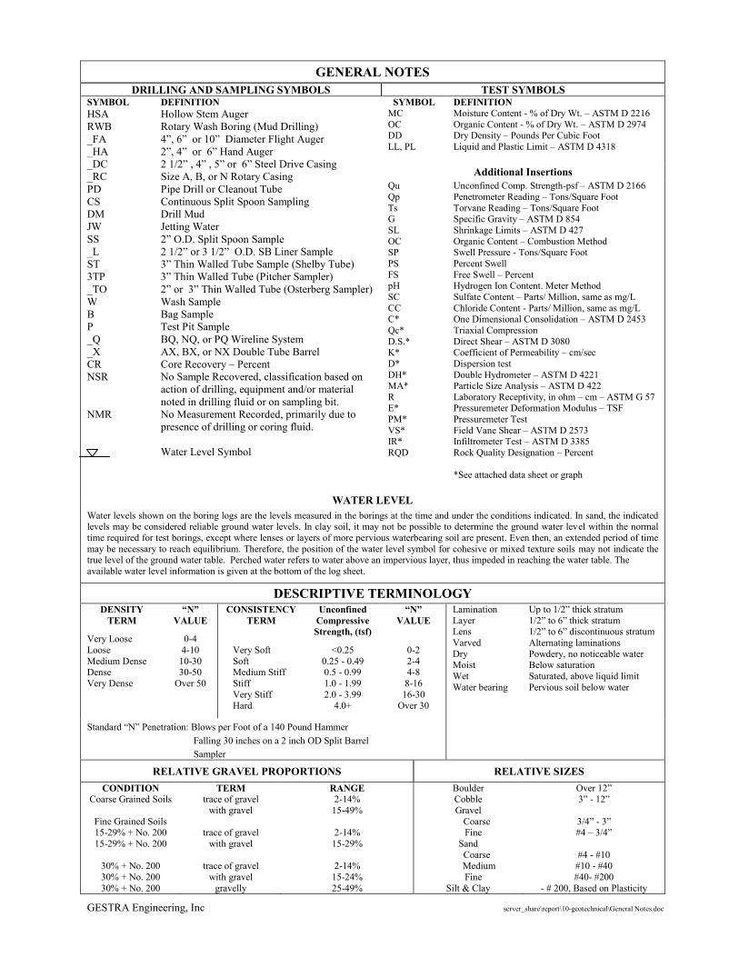
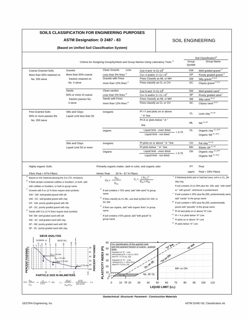
The borehole was initiated and advanced by using 3¼ inch hollow stem augers to 20 feet and then converted to rotary wash boring (RWB) technique. During drilling, soil samples were collected at 2½ foot intervals to 16 feet and then at 5 foot intervals to the termination depth of the borings. All representative soil samples were taken in general accordance with the “Standard Method for Penetration Test and Split-Barrel Sampling of Soils” (ASTM D1586). The soil samples were visually and manually classified in the field by the crew in accordance with ASTM: D2487-93 and D2488-93. Representative portions of the samples were then returned to the laboratory for further examination and for verification of the field classification.
All of the retained soil samples were classified by a geotechnical engineer using the Unified Soil Classification System. A chart describing the classification system used is included in the Appendix of this report. The engineer assigned laboratory testing suited to extract important index properties of the soil layers. These tests included hand penetrometer, moisture content, organic content, P200, Atterberg limits, dry density and unconfined compressive strength and the individual lab test results can be found in Appendix II of this report on the attached boring logs.
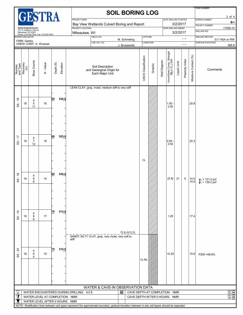
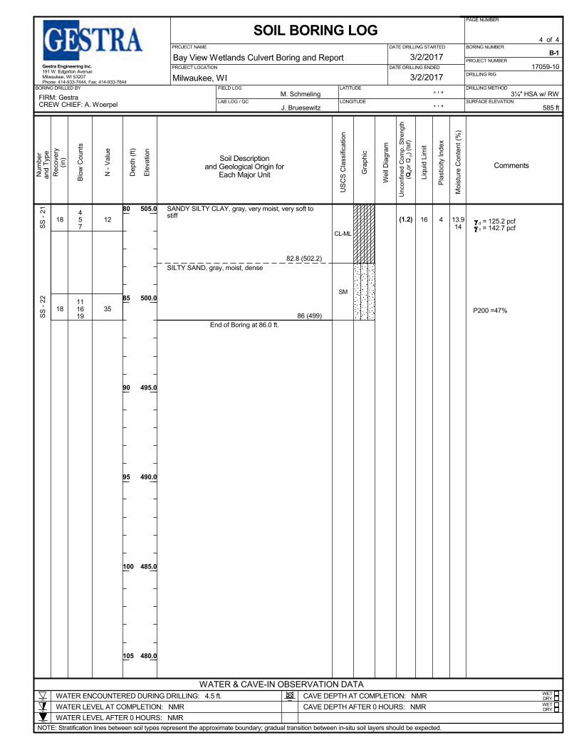
3.2 Subsurface Soil Profile The results of the field observations and laboratory tests are depicted on the test boring log included in Appendix I of this report. Soils were grouped together based on similar observed properties and stratification lines were estimated by the reviewing engineer based on the available data and experience. The actual in-situ changes between layers may differ slightly and may be more gradual than depicted on the boring log. Subsurface and groundwater conditions may vary in areas not explored by GESTRA.
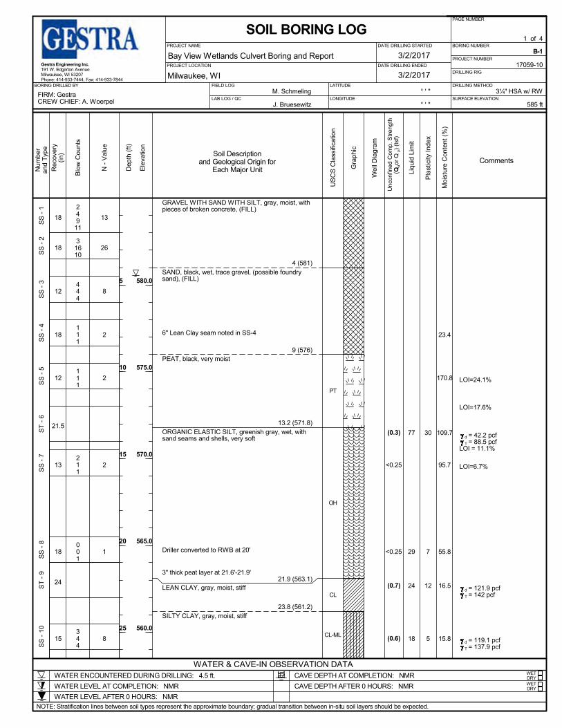
The engineering analysis and foundation recommendations presented in this report are based on soil information obtained primarily from soil boring B-1. The surface elevation at the boring location was approximately 585 feet. Granular fill was encountered at the surface of the borehole to an elevation of 576 feet. The fill material was generally gray gravel with silt and sand to an elevation of 581 feet underlain by black sand fill to 576 feet.
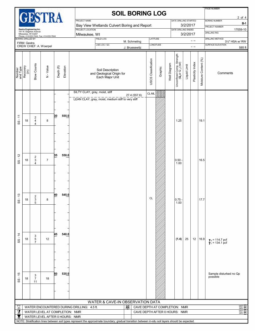
Below fill material, very soft/very loose black organic peat was observed to an elevation of 571.8 feet; very soft greenish gray organic silt to an elevation of 563.1 feet; medium stiff to very stiff gray lean clay and/or silty clay to an elevation of 502.2 feet and dense gray silty sand to the termination depth at an elevation of 499 feet. Details of SPT N-values, and test results are presented in the boring log attached to this report.
It is important to note that the soil observations and thickness estimates were made in small diameter boreholes. Therefore, it should be understood that thicker or thinner deposits of the individual strata are likely to be encountered in the project area. Furthermore, the estimation of soil layer thickness at a particular location can differ from person to person due to sometime indistinct transition between the soils and the condition below the roadway will likely vary somewhat from our boring location due to previous construction.
Proposed Bay View Wetlands Culvert, Milwaukee, WI March 21, 2017
GESTRA Engineering, Inc. Page 4 17059-10
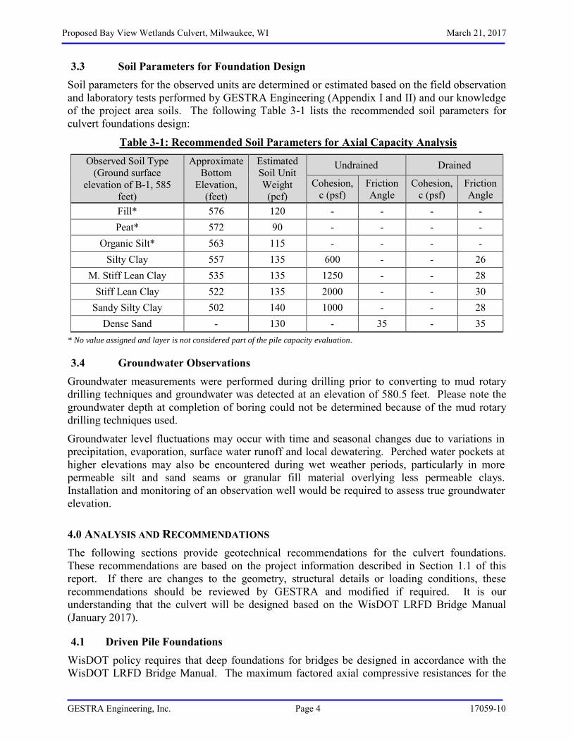
3.3 Soil Parameters for Foundation Design Soil parameters for the observed units are determined or estimated based on the field observation and laboratory tests performed by GESTRA Engineering (Appendix I and II) and our knowledge of the project area soils. The following Table 3-1 lists the recommended soil parameters for culvert foundations design:
Table 3-1: Recommended Soil Parameters for Axial Capacity Analysis Observed Soil Type
(Ground surface elevation of B-1, 585
feet)
Approximate Bottom
Elevation, (feet)
Estimated Soil Unit Weight
(pcf)
Undrained Drained
Cohesion, c (psf)
Friction Angle
Cohesion, c (psf)
Friction Angle
Fill* 576 120 - - - - Peat* 572 90 - - - -
Organic Silt* 563 115 - - - - Silty Clay 557 135 600 - - 26
M. Stiff Lean Clay 535 135 1250 - - 28 Stiff Lean Clay 522 135 2000 - - 30
Sandy Silty Clay 502 140 1000 - - 28 Dense Sand - 130 - 35 - 35
* No value assigned and layer is not considered part of the pile capacity evaluation.
3.4 Groundwater Observations Groundwater measurements were performed during drilling prior to converting to mud rotary drilling techniques and groundwater was detected at an elevation of 580.5 feet. Please note the groundwater depth at completion of boring could not be determined because of the mud rotary drilling techniques used.
Groundwater level fluctuations may occur with time and seasonal changes due to variations in precipitation, evaporation, surface water runoff and local dewatering. Perched water pockets at higher elevations may also be encountered during wet weather periods, particularly in more permeable silt and sand seams or granular fill material overlying less permeable clays. Installation and monitoring of an observation well would be required to assess true groundwater elevation.
4.0 ANALYSIS AND RECOMMENDATIONS The following sections provide geotechnical recommendations for the culvert foundations. These recommendations are based on the project information described in Section 1.1 of this report. If there are changes to the geometry, structural details or loading conditions, these recommendations should be reviewed by GESTRA and modified if required. It is our understanding that the culvert will be designed based on the WisDOT LRFD Bridge Manual (January 2017).
4.1 Driven Pile Foundations WisDOT policy requires that deep foundations for bridges be designed in accordance with the WisDOT LRFD Bridge Manual. The maximum factored axial compressive resistances for the
Proposed Bay View Wetlands Culvert, Milwaukee, WI March 21, 2017
GESTRA Engineering, Inc. Page 5 17059-10
selected pile sections have been estimated using procedures included in the WisDOT LRFD Bridge Manual (January, 2017). The maximum structural resistance is the function of pile section and material strength (i.e., mainly compressive strength). The maximum geotechnical resistance is dependent on the resistance of subsurface soils (shaft and tip resistances). Drivability is dependent on an interactive combination of the geotechnical resistance of the soils to penetration depth, and pile installation equipment (i.e., hammer type).
In consideration of the site subsurface conditions, both CIP (pipe piles) and H piles (HP) are considered suitable candidate for driven pile foundations option. Pile capacity and embedded lengths are estimated both for a closed end 10.75-inch diameter (shell thickness 0.25 inches) CIP pile and a HP 10x42 pile. The following sections estimate each of these limit states for both the pile types which are commonly used on WisDOT projects.
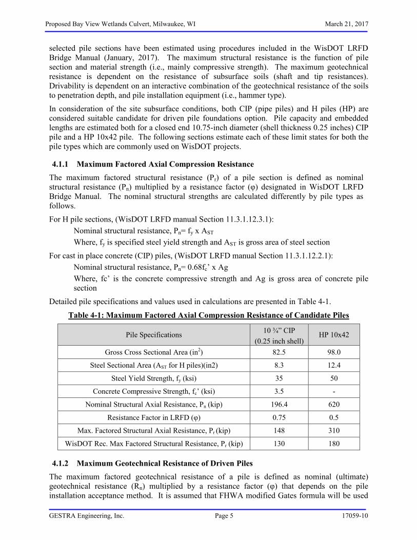
4.1.1 Maximum Factored Axial Compression Resistance The maximum factored structural resistance (Pr) of a pile section is defined as nominal structural resistance (Pn) multiplied by a resistance factor (φ) designated in WisDOT LRFD Bridge Manual. The nominal structural strengths are calculated differently by pile types as follows.
For H pile sections, (WisDOT LRFD manual Section 11.3.1.12.3.1): Nominal structural resistance, Pn= fy x AST Where, fy is specified steel yield strength and AST is gross area of steel section
For cast in place concrete (CIP) piles, (WisDOT LRFD manual Section 11.3.1.12.2.1): Nominal structural resistance, Pn= 0.68fc’ x Ag Where, fc’ is the concrete compressive strength and Ag is gross area of concrete pile section
Detailed pile specifications and values used in calculations are presented in Table 4-1.
Table 4-1: Maximum Factored Axial Compression Resistance of Candidate Piles
Pile Specifications 10 ¾” CIP (0.25 inch shell)
HP 10x42
Gross Cross Sectional Area (in2) 82.5 98.0
Steel Sectional Area (AST for H piles)(in2) 8.3 12.4
Steel Yield Strength, fy (ksi) 35 50
Concrete Compressive Strength, fc’ (ksi) 3.5 -
Nominal Structural Axial Resistance, Pn (kip) 196.4 620
Resistance Factor in LRFD (φ) 0.75 0.5
Max. Factored Structural Axial Resistance, Pr (kip) 148 310
WisDOT Rec. Max Factored Structural Resistance, Pr (kip) 130 180
4.1.2 Maximum Geotechnical Resistance of Driven Piles The maximum factored geotechnical resistance of a pile is defined as nominal (ultimate) geotechnical resistance (Rn) multiplied by a resistance factor (φ) that depends on the pile installation acceptance method. It is assumed that FHWA modified Gates formula will be used
Proposed Bay View Wetlands Culvert, Milwaukee, WI March 21, 2017
GESTRA Engineering, Inc. Page 6 17059-10
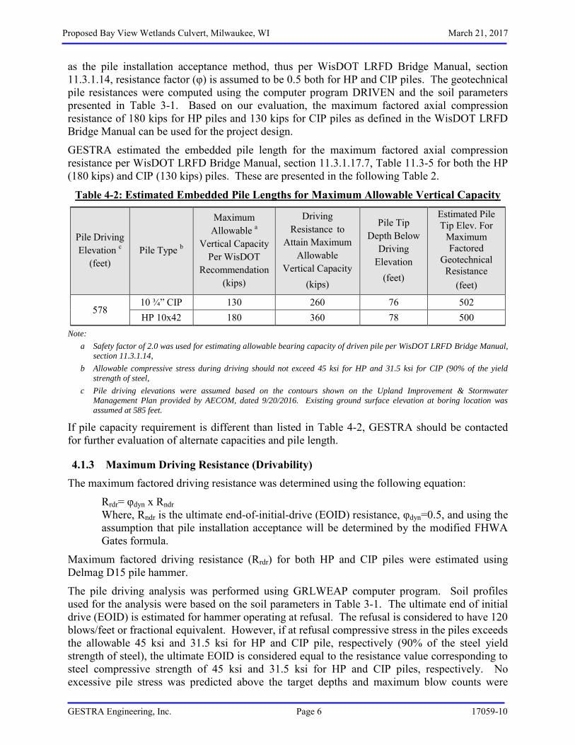
as the pile installation acceptance method, thus per WisDOT LRFD Bridge Manual, section 11.3.1.14, resistance factor (φ) is assumed to be 0.5 both for HP and CIP piles. The geotechnical pile resistances were computed using the computer program DRIVEN and the soil parameters presented in Table 3-1. Based on our evaluation, the maximum factored axial compression resistance of 180 kips for HP piles and 130 kips for CIP piles as defined in the WisDOT LRFD Bridge Manual can be used for the project design.
GESTRA estimated the embedded pile length for the maximum factored axial compression resistance per WisDOT LRFD Bridge Manual, section 11.3.1.17.7, Table 11.3-5 for both the HP (180 kips) and CIP (130 kips) piles. These are presented in the following Table 2.
Table 4-2: Estimated Embedded Pile Lengths for Maximum Allowable Vertical Capacity
Pile Driving Elevation c
(feet) Pile Type b
Maximum Allowable a
Vertical Capacity Per WisDOT
Recommendation (kips)
Driving Resistance to
Attain Maximum Allowable
Vertical Capacity (kips)
Pile Tip Depth Below
Driving Elevation
(feet)
Estimated Pile Tip Elev. For
Maximum Factored
Geotechnical Resistance
(feet)
578 10 ¾” CIP 130 260 76 502 HP 10x42 180 360 78 500
Note:
a Safety factor of 2.0 was used for estimating allowable bearing capacity of driven pile per WisDOT LRFD Bridge Manual,
section 11.3.1.14,
b Allowable compressive stress during driving should not exceed 45 ksi for HP and 31.5 ksi for CIP (90% of the yield
strength of steel,
c Pile driving elevations were assumed based on the contours shown on the Upland Improvement & Stormwater
Management Plan provided by AECOM, dated 9/20/2016. Existing ground surface elevation at boring location was
assumed at 585 feet.
If pile capacity requirement is different than listed in Table 4-2, GESTRA should be contacted for further evaluation of alternate capacities and pile length.
4.1.3 Maximum Driving Resistance (Drivability) The maximum factored driving resistance was determined using the following equation:
Rrdr= φdyn x Rndr Where, Rndr is the ultimate end-of-initial-drive (EOID) resistance, φdyn=0.5, and using the assumption that pile installation acceptance will be determined by the modified FHWA Gates formula.
Maximum factored driving resistance (Rrdr) for both HP and CIP piles were estimated using Delmag D15 pile hammer.
The pile driving analysis was performed using GRLWEAP computer program. Soil profiles used for the analysis were based on the soil parameters in Table 3-1. The ultimate end of initial drive (EOID) is estimated for hammer operating at refusal. The refusal is considered to have 120 blows/feet or fractional equivalent. However, if at refusal compressive stress in the piles exceeds the allowable 45 ksi and 31.5 ksi for HP and CIP pile, respectively (90% of the steel yield strength of steel), the ultimate EOID is considered equal to the resistance value corresponding to steel compressive strength of 45 ksi and 31.5 ksi for HP and CIP piles, respectively. No excessive pile stress was predicted above the target depths and maximum blow counts were

Proposed Bay View Wetlands Culvert, Milwaukee, WI March 21, 2017
GESTRA Engineering, Inc. Page 7 17059-10
observed below 25 blows per foot of penetration, which is below the minimum blow count requirement for set criteria. Therefore, drivability analysis results are not presented in this report.
Please note an actual refusal bearing layer was not encountered within the drilled depth. The majority of pile capacity is estimated from friction resistance. Drivability analysis indicated that minimum pile set requirement criteria per WisDOT LRFD Bridge Manual (25 blows per foot of penetration) will not be met during driving. Therefore, we recommend pile set criteria should be driven to the length presented in Table 4-2.
4.1.4 Downdrag Force on driven Pile Foundation A grade change is not planned at the culvert location. Therefore downdrag force is not expected to be a concern for the piles.
4.1.5 Pile Spacing The minimum and maximum pile spacing should be based on the recommendation provided in the WisDOT LRFD Bridge Manual, Section 11.3.1.2. According to the manual, the minimum pile spacing is 2 feet-6 inches or 2.5 pile diameters, whichever is greater. For displacement pile with estimated lengths ≥ 100 feet, the minimum pile spacing is 3.0 pile diameters. The maximum pile spacing is 8 feet for abutments, pile encased piers and pile bents, based on standard substructure designs.
4.1.6 Lateral Squeeze Potential It is our understanding that the final grade on the roadway on top of the culvert will be similar to the existing elevation, so that no new fill loads will be added. The facing slope in front of the culvert wall is assumed vertical and the piles will be installed at depth below the bottom of culvert. No grade change is planned at the existing culvert location; therefore, pile lateral squeeze is not a concern at these locations.
4.1.7 Estimated Settlement No grade change is planned at the proposed culvert foundation locations. Therefore, settlement is not expected to be significant at culvert foundation locations.
4.2 Construction Consideration
4.2.1 Excavation Safety Caving is a common issue for excavation side walls during construction, especially if fill material, granular soils, and/or water seepage is observed. An excavation plan should be developed and the length of excavation left open should be limited to prevent caving soil from covering the suitable bearing soils. The contractor must comply with the federal, state, local and updated OSHA regulations in retention system design to ensure excavation safety.
Occupational Safety and Health Act (OSHA) has instituted strict standards for temporary construction excavations. These standards are outlined in 29 CFR Part 1926 Subpart P. Excavations within unstable soil conditions or extending five feet or more in depth should be adequately sloped or braced according to these standards. Excavation safety is the responsibility of the contractor. Material stockpiles or heavy equipment should not be placed near the edge of
Proposed Bay View Wetlands Culvert, Milwaukee, WI March 21, 2017
GESTRA Engineering, Inc. Page 8 17059-10
the excavation slopes. The actual stable slope angle should be determined during construction by the contractor and will depend upon the loading, soil, and groundwater conditions encountered.
4.2.2 Construction Dewatering Based on the observed soil and groundwater conditions, dewatering is expected to be required during the excavation and construction of the culvert structure foundations. The contractor should provide a construction dewatering system plan adequate for proper construction of the structure and submit it to the Design Engineer for approval.
4.2.3 Temporary Soil Retention System The expected bottom of foundation grade at 578 feet is about 7 feet lower than the existing roadway elevation. Therefore, the excavation is expected to extend through variable soil conditions. A portion of the excavation is anticipated to be extended below the groundwater level (assumed water at elevation 580.5 feet based on the exploration results).
Based on the observed soil profile and depth to groundwater, the excavation may require a temporary soil retention system for the proposed construction. The details of the retention system, if required, shall be designed by the installation contractor and should be reviewed by the project team for completeness and adequacy. The presence, if any, of any underground utilities must be considered in the design of the temporary retention system.
4.2.4 Limitations This report was prepared for the specific project discussed herein. The project details are unique relative to the structure location, size, configuration and elevations. Where specific information was not available, assumptions have been made, and are noted as such. These assumptions need to be reviewed by the engineer and other design professionals working on this project to confirm that these are correct for the planned use and project. If these assumptions are not correct, GESTRA geotechnical engineers should be informed and allowed to modify this report, its conclusions, and recommendations.
The accuracy and completeness of any documents or information provided by others as to project specifics have been reasonably relied on by GESTRA in providing its evaluation. In addition, if details of the planned construction change from those outlined in this report, GESTRA geotechnical engineers must be notified to determine if the changes affect the recommendations. Supplemental recommendations may then need to be made.
The analysis, conclusions, and recommendations in this report are based on the subsurface conditions present at the boring location and the engineering characteristics of the soil as determined through field and laboratory testing at this point in time, as defined in the current work scope. Subsurface conditions can change over time due to both natural and human forces, including changes in condition or use of adjacent properties.
Variations in soil conditions should be expected between or beyond the borings, or between sample intervals, the nature and extent of which might not become evident until construction is undertaken. It is recommended observation and testing of the construction be performed by a GESTRA geotechnical engineer or authorize competent personnel to determine if the subsurface conditions are as indicated by the boring and perform as anticipated.
If the conditions encountered during construction are different from those inferred by the borings or the project details and information changes, the geotechnical engineer must be

Proposed Bay View Wetlands Culvert, Milwaukee, WI March 21, 2017
GESTRA Engineering, Inc. Page 9 17059-10
contacted to determine if modification to the recommendations presented in this report are required. The recommendations found in this report are related and are not mutually exclusive of each other. Therefore, no single portion of this report should be removed or be considered as a stand-alone recommendation. The boring logs must also remain with the report, as it is not to be interpreted on its own.
The geotechnical recommendations presented herein are an evaluation of subsoil performance based on the geotechnical engineers' experience and professional opinion. Analysis in this report is specific to the structure location as provided to us. If the location is revised, we must be given the opportunity to evaluate conditions at the revised location. These services were performed with the degree of skill and care normally utilized by other members of the geotechnical engineering profession practicing at this location at this time. No warranty is either expressed or implied.
This report is intended for structure design and construction purposes only and does not document the presence or absence of any environmental and hydrological impacts at the site. Environmental and hydrological services were specifically beyond the authorized scope of services.
Any use or reuse of this report for any purpose other than as specifically intended hereunder without written verification by the geotechnical engineer shall be at the user's own risk..
Sincerely, GESTRA Engineering, Inc. Report Prepared By: Report Reviewed By:
Razaul Haque, P.E. Douglas Dettmers, P.E. Project Engineer Senior Engineer

Proposed Bay View Wetlands Culvert, Milwaukee, WI
GESTRA Engineering, Inc. 17059-10
APPENDIX I
BOREHOLE LAYOUT PLAN, TEST BORING LOGS, AND NOMENCLATURE
Project Name & Location: Proposed Bay View Wetlands Culvert 100 South Marina Drive Milwaukee, Wisconsin
Drawing Title: Borehole Layout Plan
Project Number: 17059-10
Drawn by: R. Haque
GESTRA Engineering, Inc. 191 W. Edgerton Avenue Milwaukee, WI 53207 Ph: 414 933 7444 Fax: 414 933 7844
Scale: As Shown
Date: March 08, 2017
Checked & Approved by: V. Streich
LEGEND:
B-#: Borings Identification
Boring Location
Probe Location
NOTE:
Redrawn using draft drawing
Alternate 5 Plan- Upland
Improvement & Stormwater
Management dated 2016-09-20,
Sheet No. C-08 prepared by
AECOM Technical Services, Inc.
B-1
PT
OH
CL
CL-ML
18
18
12
18
12
21.5
13
18
24
15
30
7
12
5
24911
31610
444
111
111
211
001
344
77
29
24
18
GRAVEL WITH SAND WITH SILT, gray, moist, withpieces of broken concrete, (FILL)
4 (581)SAND, black, wet, trace gravel, (possible foundrysand), (FILL)
6" Lean Clay seam noted in SS-4
9 (576)PEAT, black, very moist
13.2 (571.8)ORGANIC ELASTIC SILT, greenish gray, wet, withsand seams and shells, very soft
Driller converted to RWB at 20'
3" thick peat layer at 21.6'-21.9'21.9 (563.1)
LEAN CLAY, gray, moist, stiff
23.8 (561.2)SILTY CLAY, gray, moist, stiff
23.4
170.8
109.7
95.7
55.8
16.5
15.8
13
26
8
2
2
2
1
8
LOI=24.1%
LOI=17.6%
d = 42.2 pcf T = 88.5 pcf
LOI = 11.1%
LOI=6.7%
d = 121.9 pcf T = 142 pcf
d = 119.1 pcf T = 137.9 pcf
SS
- 1
SS
- 2
SS
- 3
SS
- 4
SS
- 5
ST
- 6S
S -
7S
S -
8S
T - 9
SS
- 10
(0.3)
<0.25
<0.25
(0.7)
(0.6)
FIELD LOG
Comments
WETDRY
3/2/2017
Dep
th (f
t)
Ele
vatio
n
J. Bruesewitz
17059-10
BORING NUMBER
NOTE: Stratification lines between soil types represent the approximate boundary; gradual transition between in-situ soil layers should be expected.
PAGE NUMBER
WETDRY
FIRM: GestraCREW CHIEF: A. Woerpel
5
10
15
20
25
WATER LEVEL AFTER 0 HOURS: NMR
CAVE DEPTH AT COMPLETION: NMR
Milwaukee, WI
US
CS
Cla
ssifi
catio
n
1 of 4
DRILLING RIG
DRILLING METHODBORING DRILLED BY
Rec
over
y(in
)
Gra
phic
Soil Descriptionand Geological Origin for
Each Major Unit
580.0
575.0
570.0
565.0
560.0
LATITUDE
Unc
onfin
ed C
omp.
Stre
ngth
(Quo
r Qp)
(tsf
)
Moi
stur
e C
onte
nt (%
)
DATE DRILLING STARTED
Blo
w C
ount
s
M. Schmeling
WATER & CAVE-IN OBSERVATION DATA
PROJECT NUMBER
Num
ber
and
Type
WATER ENCOUNTERED DURING DRILLING: 4.5 ft.
B-1
N -
Val
ue
Bay View Wetlands Culvert Boring and ReportDATE DRILLING ENDED
PROJECT NAME
PROJECT LOCATION
SURFACE ELEVATION
Liqu
id L
imit
3/2/2017
LONGITUDE
WATER LEVEL AT COMPLETION: NMR CAVE DEPTH AFTER 0 HOURS: NMR
SOIL BORING LOG
Gestra Engineering Inc.191 W. Edgerton AvenueMilwaukee, WI 53207Phone: 414-933-7444, Fax: 414-933-7844
Pla
stic
ity In
dex
LAB LOG / QC3¼" HSA w/ RW
585 ft° ' "
° ' "
Wel
l Dia
gram
CL-ML
CL
18
18
18
18
18
12
244
234
235
357
3711
25
SILTY CLAY, gray, moist, stiff27.4 (557.6)
LEAN CLAY, gray, moist, medium stiff to very stiff
19.1
16.5
17.7
16.9
8
7
8
12
18
d = 114.7 pcf T = 134.1 pcf
Sample disturbed no Qppossible
SS
- 11
SS
- 12
SS
- 13
SS
- 14
SS
- 15
1.25
0.50 -1.00
0.75 -1.00
(1.4)
FIELD LOG
Comments
WETDRY
3/2/2017
Dep
th (f
t)
Ele
vatio
n
J. Bruesewitz
17059-10
BORING NUMBER
NOTE: Stratification lines between soil types represent the approximate boundary; gradual transition between in-situ soil layers should be expected.
PAGE NUMBER
WETDRY
FIRM: GestraCREW CHIEF: A. Woerpel
30
35
40
45
50
WATER LEVEL AFTER 0 HOURS: NMR
CAVE DEPTH AT COMPLETION: NMR
Milwaukee, WI
US
CS
Cla
ssifi
catio
n
2 of 4
DRILLING RIG
DRILLING METHODBORING DRILLED BY
Rec
over
y(in
)
Gra
phic
Soil Descriptionand Geological Origin for
Each Major Unit
555.0
550.0
545.0
540.0
535.0
LATITUDE
Unc
onfin
ed C
omp.
Stre
ngth
(Quo
r Qp)
(tsf
)
Moi
stur
e C
onte
nt (%
)
DATE DRILLING STARTED
Blo
w C
ount
s
M. Schmeling
WATER & CAVE-IN OBSERVATION DATA
PROJECT NUMBER
Num
ber
and
Type
WATER ENCOUNTERED DURING DRILLING: 4.5 ft.
B-1
N -
Val
ue
Bay View Wetlands Culvert Boring and ReportDATE DRILLING ENDED
PROJECT NAME
PROJECT LOCATION
SURFACE ELEVATION
Liqu
id L
imit
3/2/2017
LONGITUDE
WATER LEVEL AT COMPLETION: NMR CAVE DEPTH AFTER 0 HOURS: NMR
SOIL BORING LOG
Gestra Engineering Inc.191 W. Edgerton AvenueMilwaukee, WI 53207Phone: 414-933-7444, Fax: 414-933-7844
Pla
stic
ity In
dex
LAB LOG / QC3¼" HSA w/ RW
585 ft° ' "
° ' "
Wel
l Dia
gram
CL
CL-ML
18
18
18
18
18
9
4511
5712
468
498
464
21
LEAN CLAY, gray, moist, medium stiff to very stiff
72.8 (512.2)SANDY SILTY CLAY, gray, very moist, very soft tostiff
20.8
20.3
14.514.6
17.4
15.8
16
19
14
17
10
d = 121.5 pcf T = 139.2 pcf
P200 =69.8%
SS
- 16
SS
- 17
SS
- 18
SS
- 19
SS
- 20
1.50 -2.50
2.00 -2.50
(1.1)
1.25
<0.25
FIELD LOG
Comments
WETDRY
3/2/2017
Dep
th (f
t)
Ele
vatio
n
J. Bruesewitz
17059-10
BORING NUMBER
NOTE: Stratification lines between soil types represent the approximate boundary; gradual transition between in-situ soil layers should be expected.
PAGE NUMBER
WETDRY
FIRM: GestraCREW CHIEF: A. Woerpel
55
60
65
70
75
WATER LEVEL AFTER 0 HOURS: NMR
CAVE DEPTH AT COMPLETION: NMR
Milwaukee, WI
US
CS
Cla
ssifi
catio
n
3 of 4
DRILLING RIG
DRILLING METHODBORING DRILLED BY
Rec
over
y(in
)
Gra
phic
Soil Descriptionand Geological Origin for
Each Major Unit
530.0
525.0
520.0
515.0
510.0
LATITUDE
Unc
onfin
ed C
omp.
Stre
ngth
(Quo
r Qp)
(tsf
)
Moi
stur
e C
onte
nt (%
)
DATE DRILLING STARTED
Blo
w C
ount
s
M. Schmeling
WATER & CAVE-IN OBSERVATION DATA
PROJECT NUMBER
Num
ber
and
Type
WATER ENCOUNTERED DURING DRILLING: 4.5 ft.
B-1
N -
Val
ue
Bay View Wetlands Culvert Boring and ReportDATE DRILLING ENDED
PROJECT NAME
PROJECT LOCATION
SURFACE ELEVATION
Liqu
id L
imit
3/2/2017
LONGITUDE
WATER LEVEL AT COMPLETION: NMR CAVE DEPTH AFTER 0 HOURS: NMR
SOIL BORING LOG
Gestra Engineering Inc.191 W. Edgerton AvenueMilwaukee, WI 53207Phone: 414-933-7444, Fax: 414-933-7844
Pla
stic
ity In
dex
LAB LOG / QC3¼" HSA w/ RW
585 ft° ' "
° ' "
Wel
l Dia
gram
CL-ML
SM
18
18
4457
111619
16SANDY SILTY CLAY, gray, very moist, very soft tostiff
82.8 (502.2)SILTY SAND, gray, moist, dense
86 (499)End of Boring at 86.0 ft.
13.914
12
35
d = 125.2 pcf T = 142.7 pcf
P200 =47%
SS
- 21
SS
- 22
(1.2)
FIELD LOG
Comments
WETDRY
3/2/2017
Dep
th (f
t)
Ele
vatio
n
J. Bruesewitz
17059-10
BORING NUMBER
NOTE: Stratification lines between soil types represent the approximate boundary; gradual transition between in-situ soil layers should be expected.
PAGE NUMBER
WETDRY
FIRM: GestraCREW CHIEF: A. Woerpel
80
85
90
95
100
105
WATER LEVEL AFTER 0 HOURS: NMR
CAVE DEPTH AT COMPLETION: NMR
Milwaukee, WI
US
CS
Cla
ssifi
catio
n
4 of 4
DRILLING RIG
DRILLING METHODBORING DRILLED BY
Rec
over
y(in
)
Gra
phic
Soil Descriptionand Geological Origin for
Each Major Unit
505.0
500.0
495.0
490.0
485.0
480.0
LATITUDE
Unc
onfin
ed C
omp.
Stre
ngth
(Quo
r Qp)
(tsf
)
Moi
stur
e C
onte
nt (%
)
DATE DRILLING STARTED
Blo
w C
ount
s
M. Schmeling
WATER & CAVE-IN OBSERVATION DATA
PROJECT NUMBER
Num
ber
and
Type
WATER ENCOUNTERED DURING DRILLING: 4.5 ft.
B-1
N -
Val
ue
Bay View Wetlands Culvert Boring and ReportDATE DRILLING ENDED
PROJECT NAME
PROJECT LOCATION
SURFACE ELEVATION
Liqu
id L
imit
3/2/2017
LONGITUDE
WATER LEVEL AT COMPLETION: NMR CAVE DEPTH AFTER 0 HOURS: NMR
SOIL BORING LOG
Gestra Engineering Inc.191 W. Edgerton AvenueMilwaukee, WI 53207Phone: 414-933-7444, Fax: 414-933-7844
Pla
stic
ity In
dex
LAB LOG / QC3¼" HSA w/ RW
585 ft° ' "
° ' "
Wel
l Dia
gram
GESTRA Engineering, Inc server_share\report\10-geotechnical\General Notes.doc
GENERAL NOTES DRILLING AND SAMPLING SYMBOLS TEST SYMBOLS
SYMBOL HSA RWB _FA _HA _DC _RC PD CS DM JW SS _L ST 3TP _TO W B P _Q _X CR NSR NMR
DEFINITION Hollow Stem Auger Rotary Wash Boring (Mud Drilling) 4”, 6” or 10” Diameter Flight Auger 2”, 4” or 6” Hand Auger 2 1/2” , 4” , 5” or 6” Steel Drive Casing Size A, B, or N Rotary Casing Pipe Drill or Cleanout Tube Continuous Split Spoon Sampling Drill Mud Jetting Water 2” O.D. Split Spoon Sample 2 1/2” or 3 1/2” O.D. SB Liner Sample 3” Thin Walled Tube Sample (Shelby Tube) 3” Thin Walled Tube (Pitcher Sampler) 2” or 3” Thin Walled Tube (Osterberg Sampler) Wash Sample Bag Sample Test Pit Sample BQ, NQ, or PQ Wireline System AX, BX, or NX Double Tube Barrel Core Recovery – Percent No Sample Recovered, classification based on action of drilling, equipment and/or material noted in drilling fluid or on sampling bit. No Measurement Recorded, primarily due to presence of drilling or coring fluid. Water Level Symbol
SYMBOL MC OC DD LL, PL
DEFINITION Moisture Content - % of Dry Wt. – ASTM D 2216 Organic Content - % of Dry Wt. – ASTM D 2974 Dry Density – Pounds Per Cubic Foot Liquid and Plastic Limit – ASTM D 4318
Additional Insertions Qu Qp Ts G SL OC SP PS FS pH SC CC C* Qc* D.S.* K* D* DH* MA* R E* PM* VS* IR* RQD
Unconfined Comp. Strength-psf – ASTM D 2166 Penetrometer Reading – Tons/Square Foot Torvane Reading – Tons/Square Foot Specific Gravity – ASTM D 854 Shrinkage Limits – ASTM D 427 Organic Content – Combustion Method Swell Pressure - Tons/Square Foot Percent Swell Free Swell – Percent Hydrogen Ion Content. Meter Method Sulfate Content – Parts/ Million, same as mg/L Chloride Content - Parts/ Million, same as mg/L One Dimensional Consolidation – ASTM D 2453 Triaxial Compression Direct Shear – ASTM D 3080 Coefficient of Permeability – cm/sec Dispersion test Double Hydrometer – ASTM D 4221 Particle Size Analysis – ASTM D 422 Laboratory Receptivity, in ohm – cm – ASTM G 57 Pressuremeter Deformation Modulus – TSF Pressuremeter Test Field Vane Shear – ASTM D 2573 Infiltrometer Test – ASTM D 3385 Rock Quality Designation – Percent *See attached data sheet or graph
WATER LEVEL Water levels shown on the boring logs are the levels measured in the borings at the time and under the conditions indicated. In sand, the indicated levels may be considered reliable ground water levels. In clay soil, it may not be possible to determine the ground water level within the normal time required for test borings, except where lenses or layers of more pervious waterbearing soil are present. Even then, an extended period of time may be necessary to reach equilibrium. Therefore, the position of the water level symbol for cohesive or mixed texture soils may not indicate the true level of the ground water table. Perched water refers to water above an impervious layer, thus impeded in reaching the water table. The available water level information is given at the bottom of the log sheet.
DESCRIPTIVE TERMINOLOGY DENSITY
TERM Very Loose Loose Medium Dense Dense Very Dense
“N” VALUE
0-4 4-10
10-30 30-50
Over 50
CONSISTENCY TERM
Very Soft Soft Medium Stiff Stiff Very Stiff Hard
Unconfined Compressive Strength, (tsf)
<0.25 0.25 - 0.49 0.5 - 0.99 1.0 - 1.99 2.0 - 3.99
4.0+
“N” VALUE
0-2 2-4 4-8 8-16
16-30 Over 30
Lamination Layer Lens Varved Dry Moist Wet Water bearing
Up to 1/2” thick stratum 1/2” to 6” thick stratum 1/2” to 6” discontinuous stratum Alternating laminations Powdery, no noticeable water Below saturation Saturated, above liquid limit Pervious soil below water
Standard “N” Penetration: Blows per Foot of a 140 Pound Hammer Falling 30 inches on a 2 inch OD Split Barrel Sampler
RELATIVE GRAVEL PROPORTIONS RELATIVE SIZES CONDITION
Coarse Grained Soils
Fine Grained Soils 15-29% + No. 200 15-29% + No. 200
30% + No. 200 30% + No. 200 30% + No. 200
TERM trace of gravel
with gravel
trace of gravel with gravel
trace of gravel
with gravel gravelly
RANGE 2-14%
15-49%
2-14% 15-29%
2-14%
15-24% 25-49%
Boulder Cobble Gravel
Coarse Fine Sand
Coarse Medium
Fine Silt & Clay
Over 12” 3” - 12”
3/4” - 3” #4 – 3/4”
#4 - #10
#10 - #40 #40- #200
- # 200, Based on Plasticity
Group
Symble
Coarse-Grained Soils Gravels Clean Gravels Less
than 5% fines C
Cu≥ 4 and 1≤ Cc ≤3E GW Well graded gravel
F
More than 50% retained on More than 50% coarse Less than 5% fines C
Cu< 4 and/or 1> Cc >3E GP Poorly graded gravel
F
No. 200 sieve fraction retained on Gravels with Fines
More than 12% fines C
GM Silty gravel F.G.H.
No. 4 sieve more than 12% fines C GC Clayey gravel
F.G.H.
Sands Clean sandss Cu≥ 6 and 1≤ Cc ≤3E SW Well graded sand
I
50% or more of coarse Less than 5% fines D
Cu< 6 and/or 1> Cc >3E SP Poorly graded sand
I
fraction passes No. Sands with Fines
More than 12% fines D
SM Silty sand G.H.I
4 sieve more than 12% fines D SC Clayey sand
G.H.I
Fine-Grained Soils Silts and Clays inorganic PI >7 and plots on or above
50% or more passes the Liquid Limit less than 50 " A" line
No. 200 sieve PI<4 or plots below " A "
line
organic OL Organic clay K.L.M.N
Organic Silt K.L.M.O
Silts and Clays inorganic PI plots on or above " A " line CH Fat clay K.L.M
Liquid Limit 50 or more PI plots below " A " line MH Elastic silt K.L.M
Organic OH Organic clay K.L.M.P
Organic Silt K.L.M.Q
Highly organic Soils Primarily organic matter, dark in color, and organic odor PT Peat
Fibric Peat > 67% Fibers Hemic Peat 33 % - 67 % Fiberssapric Peat < 33% Fibers
ABased on the material passing the 3-in (75- mm)sieve
E ( D30 )2 J
If Atterberg limits plot in hatched area, soil is a CL_ML
BIf field sample contained cobbles or boulders, or both. add D10 x D60 silty clay
with cobbles or boulders, or both to group name If soil contains 15 to 29% plus No. 200, add, "with sand"
CGravels with 5 to 12 % fines require dual symbols:
FIf soil contains ≥ 15% sand, add "with sand" to group or " with gravel", whichever is predominent
GW - GM well-graded gravel with silt name LIf soil contains ≥ 30% plus No.200, predominantly sand,
GW - GC well-graded gravel with clayG
If fines classify as CL-ML, use dual symbol GC-GM. or add "sandy" to the group name
GP - GM poorly-graded gravel with Silt SC-SM MIf soil contains ≥ 30% plus No.200, predominantly
GP - GC poorly-graded gravel with clayH
If fines are organic, add "with organic fines" to group gravel add "gravelly" to the group name
DSands with 5 to 12 % fines require dual symbols: name. N
PI ≥4 and plots on or above "A" Line
SW -SM well-graded sand with siltI
If soil contains ≥15% gravel, add "with gravel" to O
PI < 4 or plots below "A" Line
SW - SC well-graded sand with clay group name. PPI plots on or above "A" Line
SP - SM poorly-graded sand with SiltQ
PI plots below "A" Line
SP - SC poorly-graded sand with clay
< 0.75
Cc =
Liquid limit - not dried
"A" l
ine
"U" li
ne
Liquid limit - oven dried< 0.75
Liquid limit - not dried
Fines Classify as ML or MH
Fines classify as CL or CH
Lean clay K.L.M
ML Silt K.L.M
Liquid limit - oven dried
CL
SOIL ENGINEERING
Soil ClassificationB
Group NameCriteria for Assigning GroupSymbols and Group Names Using Laboratory Tests A
SOILS CLASSIFICATION FOR ENGINEERING PURPOSES
ASTM Designation: D 2487 - 83
(Based on Unified Soil Classification System)
Fines Classify as ML or MH
Fines classify as CL or CH
"A" l
ine
"U" li
ne
CH OR O
H
CH OR O
H
CL OR O
L
MH OR OH
D60
D10
Geotechnical -Structural- Pavement - Construction Materials
ML or OL
CL OR O
L
Cu=
0
10
20
30
40
50
60
0 10 20 30 40 50 60 70 80 90 100 110
PL
AS
TIC
ITY
IN
DE
X (
PI)
LIQUID LIMIT (LL)
47 CL - ML
For classification of fine grained soilsand fine-grained fraction of coarse - grainedSoils.
Equation of "A" - LineHorizontal at PI = 4 to LL=25.5then PI = 0.73 (LL-20)
Equation of "U" - LineVertical at LL = 16 to PI=7then PI = 0.9 (LL-8)
16
0102030405060708090
100
0.0
1
0.11
10
3 2 1 1
/2
1 3/4
3/8
#4
#10
#40
#100
#200
100
80
60
40
20
00
SIEVE NO.SCREEN -in
PARTICLE SIZE IN MILIMETERS
SIEVE ANALYSIS
PE
RC
EN
T P
AS
SIN
G
PE
RC
EN
T R
ET
AIN
ED
D30= 2.5 mm
D10= 0.75 mm
D60 = 15 mm
═15
0.075 ═ 200 Cc =
(D30)2
D60X D10
= 15X 0.075
(2.5) 2
= 5.6
D60 = 15 mm
D60
D10
Cu =
GESTRA Engineering, Inc ASTM D2487-83, Classification.xls
Proposed Bay View Wetlands Culvert, Milwaukee, WI
GESTRA Engineering, Inc. 17059-10
APPENDIX II
LABORATORY TEST RESULTS
GESTRA Engineering, Inc
191 W. Edgerton Ave
Milwaukee, WI 53207
Phone: (414) 933-7444; Fax: (414) 933-7844
Date:
Report To:
Project Location:
D2216, D 2974
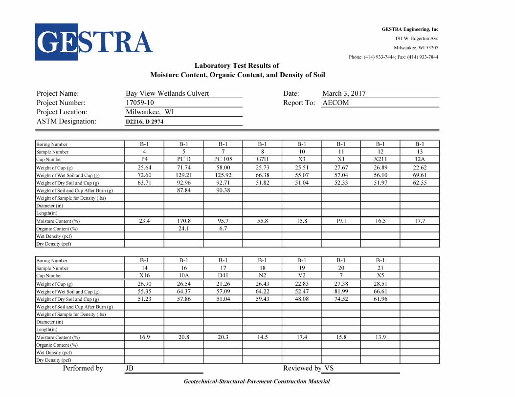
B-1 B-1 B-1 B-1 B-1 B-1 B-1 B-1
4 5 7 8 10 11 12 13
P4 PC D PC 105 G7H X3 X1 X211 12A
25.64 71.74 58.00 25.73 25.51 27.67 26.89 22.62
72.60 129.21 125.92 66.38 55.07 57.04 56.10 69.61
63.71 92.96 92.71 51.82 51.04 52.33 51.97 62.55
87.84 90.38
Weight of Sample for Density (lbs)
23.4 170.8 95.7 55.8 15.8 19.1 16.5 17.7
24.1 6.7
B-1 B-1 B-1 B-1 B-1 B-1 B-1
14 16 17 18 19 20 21
X16 10A D41 N2 V2 7 X5
26.90 26.54 21.26 26.43 22.83 27.38 28.51
55.35 64.37 57.09 64.22 52.47 81.99 66.61
51.23 57.86 51.04 59.43 48.08 74.52 61.96
Weight of Sample for Density (lbs)
16.9 20.8 20.3 14.5 17.4 15.8 13.9
Performed by JB Reviewed by VS
Dry Density (pcf)
Organic Content (%)
Wet Density (pcf)
Organic Content (%)
Weight of Wet Soil and Cup (g)
Weight of Dry Soil and Cup (g)
Weight of Soil and Cup After Burn (g)
Boring Number
Sample Number
Diameter (in)
Length(in)
Moisture Content (%)
Weight of Cup (g)
Wet Density (pcf)
Dry Density (pcf)
Cup Number
Length(in)
Moisture Content (%)
March 3, 2017
AECOM
Bay View Wetlands Culvert
17059-10
Sample Number
Cup Number
Boring Number
Weight of Cup (g)
Weight of Wet Soil and Cup (g)
Weight of Dry Soil and Cup (g)
Weight of Soil and Cup After Burn (g)
Diameter (in)
Milwaukee, WI
Project Name:
Project Number:
ASTM Designation:
Laboratory Test Results of
Moisture Content, Organic Content, and Density of Soil
Geotechnical-Structural-Pavement-Construction Material
GESTRA Engineering, Inc
191 W. Edgerton Ave
Milwaukee, WI 53207
Phone: (414) 933-7444; Fax: (414) 933-7844
Date:
Report To:
Project Location:
D2216, D 2974
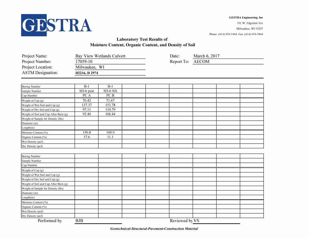
B-1 B-1
SH-6 peat SH-6 Silt
PC A PC B
70.42 71.67
137.37 153.78
97.11 110.79
92.40 106.44
Weight of Sample for Density (lbs)
150.8 109.9
17.6 11.1
Weight of Sample for Density (lbs)
Performed by BJB Reviewed byVS
Project Name:
Project Number:
ASTM Designation:
Laboratory Test Results of
Moisture Content, Organic Content, and Density of Soil
Length(in)
Moisture Content (%)
March 6, 2017
AECOM
Bay View Wetlands Culvert
17059-10
Sample Number
Cup Number
Boring Number
Weight of Cup (g)
Weight of Wet Soil and Cup (g)
Weight of Dry Soil and Cup (g)
Weight of Soil and Cup After Burn (g)
Diameter (in)
Milwaukee, WI
Dry Density (pcf)
Organic Content (%)
Wet Density (pcf)
Organic Content (%)
Weight of Wet Soil and Cup (g)
Weight of Dry Soil and Cup (g)
Weight of Soil and Cup After Burn (g)
Boring Number
Sample Number
Diameter (in)
Length(in)
Moisture Content (%)
Weight of Cup (g)
Wet Density (pcf)
Dry Density (pcf)
Cup Number
Geotechnical-Structural-Pavement-Construction Material

GESTRA Engineering, Inc
191 W. Edgerton Ave
Milwaukee, WI 53207
Phone: (414) 933-7444; Fax: (414) 933-7844
Project Name: Bay View Wetlands Culvert Date:
Project Number: 17059-10 Client: AECOM
Project Location: Milwaukee, WI
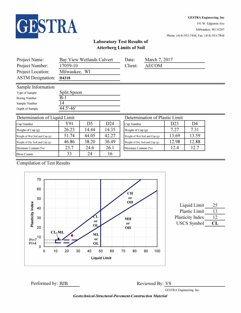
ASTM Designation: D4318
Sample InformationType of Sample Shelby TubeBoring Number B-1Sample Number 6Depth of Sample 12'-14'
Determination of Liquid Limit Determination of Plastic Limit
L20 D17 L8 Cup Number L19 D19
Weight of Cup (g) 14.21 14.64 14.49 Weight of Cup (g) 7.40 7.22
35.15 35.16 32.40 Weight of Wet Soil and Cup (g) 13.55 13.32
26.15 26.19 24.51 Weight of Dry Soil and Cup (g) 11.55 11.32
75.4 77.7 78.7 Moisture Content (%) 48.2 48.8
35 24 19
Compilation of Test Results
Liquid Limit 77
Plastic Limit 48
Plasticity Index 29
USCS Symbol MH
BJB VS
GESTRA Engineering, Inc.
Reviewed By:Performed by:
Cup Number
Blow Counts
Atterberg Limits of Soil
Laboratory Test Results of
Weight of Wet Soil and Cup (g)
Weight of Dry Soil and Cup (g)
Moisture Content (%)
March 7, 2017
CL
or
OL
CH
or
OH
MH
or
OH
CL-MLML
or
OL
PI=7
PI=40
10
20
30
40
50
60
70
0 10 20 30 40 50 60 70 80 90 100
Pla
sti
cit
y I
nd
ex
Liquid Limit
Geotechnical-Structural-Pavement-Construction Material

GESTRA Engineering, Inc
191 W. Edgerton Ave
Milwaukee, WI 53207
Phone: (414) 933-7444; Fax: (414) 933-7844
Project Name: Bay View Wetlands Culvert Date:
Project Number: 17059-10 Client: AECOM
Project Location: Milwaukee, WI
ASTM Designation: D4318
Sample InformationType of Sample Split SpoonBoring Number B-1Sample Number 8Depth of Sample 19.5'-21'
Determination of Liquid Limit Determination of Plastic Limit
L12 D9 D28 Cup Number L18 L10
Weight of Cup (g) 14.45 14.25 14.78 Weight of Cup (g) 7.32 7.14
35.82 33.85 35.80 Weight of Wet Soil and Cup (g) 13.64 13.77
31.09 29.42 30.82 Weight of Dry Soil and Cup (g) 12.51 12.59
28.4 29.2 31.0 Moisture Content (%) 21.8 21.7
32 25 18
Compilation of Test Results
Liquid Limit 30
Plastic Limit 22
Plasticity Index 8
USCS Symbol CL
BJB VS
GESTRA Engineering, Inc.
Reviewed By:Performed by:
Cup Number
Blow Counts
Atterberg Limits of Soil
Laboratory Test Results of
Weight of Wet Soil and Cup (g)
Weight of Dry Soil and Cup (g)
Moisture Content (%)
March 7, 2017
CL
or
OL
CH
or
OH
MH
or
OH
CL-MLML
or
OL
PI=7
PI=40
10
20
30
40
50
60
70
0 10 20 30 40 50 60 70 80 90 100
Pla
sti
cit
y I
nd
ex
Liquid Limit
Geotechnical-Structural-Pavement-Construction Material

GESTRA Engineering, Inc
191 W. Edgerton Ave
Milwaukee, WI 53207
Phone: (414) 933-7444; Fax: (414) 933-7844
Project Name: Bay View Wetlands Culvert Date:
Project Number: 17059-10 Client: AECOM
Project Location: Milwaukee, WI
ASTM Designation: D4318
Sample InformationType of Sample Split SpoonBoring Number B-1Sample Number 10Depth of Sample 24.5'-26'
Determination of Liquid Limit Determination of Plastic Limit
D25 B2 B32 Cup Number D27 D6
Weight of Cup (g) 14.21 14.53 14.51 Weight of Cup (g) 7.16 7.24
38.48 37.36 35.82 Weight of Wet Soil and Cup (g) 13.82 13.66
34.87 33.81 32.42 Weight of Dry Soil and Cup (g) 13.08 12.94
17.5 18.4 19.0 Moisture Content (%) 12.5 12.6
34 23 17
Compilation of Test Results
Liquid Limit 18
Plastic Limit 13
Plasticity Index 5
USCS Symbol CL-ML
BJB VS
GESTRA Engineering, Inc.
Reviewed By:Performed by:
Cup Number
Blow Counts
Atterberg Limits of Soil
Laboratory Test Results of
Weight of Wet Soil and Cup (g)
Weight of Dry Soil and Cup (g)
Moisture Content (%)
March 7, 2017
CL
or
OL
CH
or
OH
MH
or
OH
CL-MLML
or
OL
PI=7
PI=40
10
20
30
40
50
60
70
0 10 20 30 40 50 60 70 80 90 100
Pla
sti
cit
y I
nd
ex
Liquid Limit
Geotechnical-Structural-Pavement-Construction Material
GESTRA Engineering, Inc
191 W. Edgerton Ave
Milwaukee, WI 53207
Phone: (414) 933-7444; Fax: (414) 933-7844
Project Name: Bay View Wetlands Culvert Date:
Project Number: 17059-10 Client: AECOM
Project Location: Milwaukee, WI
ASTM Designation: D4318
Sample InformationType of Sample Split SpoonBoring Number B-1Sample Number 14Depth of Sample 44.5'-46'
Determination of Liquid Limit Determination of Plastic Limit
Y91 D5 D24 Cup Number D23 D4
Weight of Cup (g) 26.23 14.44 14.35 Weight of Cup (g) 7.27 7.31
51.74 44.05 42.27 Weight of Wet Soil and Cup (g) 13.69 13.59
46.86 38.20 36.49 Weight of Dry Soil and Cup (g) 12.98 12.88
23.7 24.6 26.1 Moisture Content (%) 12.4 12.7
33 24 16
Compilation of Test Results
Liquid Limit 25
Plastic Limit 13
Plasticity Index 12
USCS Symbol CL
BJB VS
GESTRA Engineering, Inc.
Reviewed By:Performed by:
Cup Number
Blow Counts
Atterberg Limits of Soil
Laboratory Test Results of
Weight of Wet Soil and Cup (g)
Weight of Dry Soil and Cup (g)
Moisture Content (%)
March 7, 2017
CL
or
OL
CH
or
OH
MH
or
OH
CL-MLML
or
OL
PI=7
PI=40
10
20
30
40
50
60
70
0 10 20 30 40 50 60 70 80 90 100
Pla
sti
cit
y I
nd
ex
Liquid Limit
Geotechnical-Structural-Pavement-Construction Material

GESTRA Engineering, Inc
191 W. Edgerton Ave
Milwaukee, WI 53207
Phone: (414) 933-7444; Fax: (414) 933-7844
Project Name: Bay View Wetlands Culvert Date:
Project Number: 17059-10 Client: AECOM
Project Location: Milwaukee, WI
ASTM Designation: D4318
Sample InformationType of Sample Split SpoonBoring Number B-1Sample Number 18Depth of Sample 64.5'-66'
Determination of Liquid Limit Determination of Plastic Limit
B11 B19 D6 Cup Number D19 G7
Weight of Cup (g) 14.38 14.40 14.58 Weight of Cup (g) 7.23 7.22
35.42 35.93 37.40 Weight of Wet Soil and Cup (g) 13.69 13.78
31.82 32.15 33.21 Weight of Dry Soil and Cup (g) 12.99 13.08
20.6 21.3 22.5 Moisture Content (%) 12.2 11.9
32 25 16
Compilation of Test Results
Liquid Limit 21
Plastic Limit 12
Plasticity Index 9
USCS Symbol CL
BJB VS
GESTRA Engineering, Inc.
Reviewed By:Performed by:
Cup Number
Blow Counts
Atterberg Limits of Soil
Laboratory Test Results of
Weight of Wet Soil and Cup (g)
Weight of Dry Soil and Cup (g)
Moisture Content (%)
March 8, 2017
CL
or
OL
CH
or
OH
MH
or
OH
CL-MLML
or
OL
PI=7
PI=40
10
20
30
40
50
60
70
0 10 20 30 40 50 60 70 80 90 100
Pla
sti
cit
y I
nd
ex
Liquid Limit
Geotechnical-Structural-Pavement-Construction Material
GESTRA Engineering, Inc
191 W. Edgerton Ave
Milwaukee, WI 53207
Phone: (414) 933-7444; Fax: (414) 933-7844
Project Name: Bay View Wetlands Culvert Date:
Project Number: 17059-10 Client: AECOM
Project Location: Milwaukee, WI
ASTM Designation: D4318
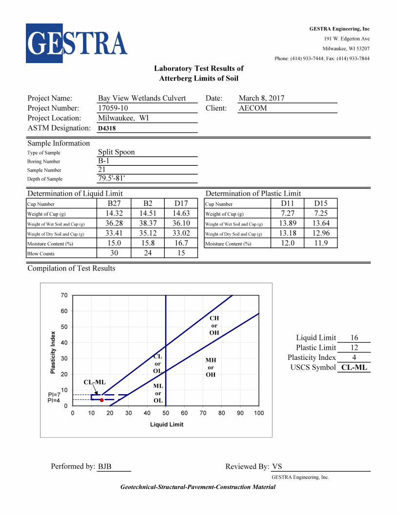
Sample InformationType of Sample Split SpoonBoring Number B-1Sample Number 21Depth of Sample 79.5'-81'
Determination of Liquid Limit Determination of Plastic Limit
B27 B2 D17 Cup Number D11 D15
Weight of Cup (g) 14.32 14.51 14.63 Weight of Cup (g) 7.27 7.25
36.28 38.37 36.10 Weight of Wet Soil and Cup (g) 13.89 13.64
33.41 35.12 33.02 Weight of Dry Soil and Cup (g) 13.18 12.96
15.0 15.8 16.7 Moisture Content (%) 12.0 11.9
30 24 15
Compilation of Test Results
Liquid Limit 16
Plastic Limit 12
Plasticity Index 4
USCS Symbol CL-ML
BJB VS
GESTRA Engineering, Inc.
Reviewed By:Performed by:
Cup Number
Blow Counts
Atterberg Limits of Soil
Laboratory Test Results of
Weight of Wet Soil and Cup (g)
Weight of Dry Soil and Cup (g)
Moisture Content (%)
March 8, 2017
CL
or
OL
CH
or
OH
MH
or
OH
CL-MLML
or
OL
PI=7
PI=40
10
20
30
40
50
60
70
0 10 20 30 40 50 60 70 80 90 100
Pla
sti
cit
y I
nd
ex
Liquid Limit
Geotechnical-Structural-Pavement-Construction Material
GESTRA Engineering, Inc
191 W. Edgerton Ave
Milwaukee, WI 53207
Phone: (414) 933-7444; Fax: (414) 933-7844
Project Name: Bay View Wetlands Culvert Date:
Project Number: 17059-10 Client: AECOM
Project Location: Milwaukee, WI
ASTM Designation: D4318
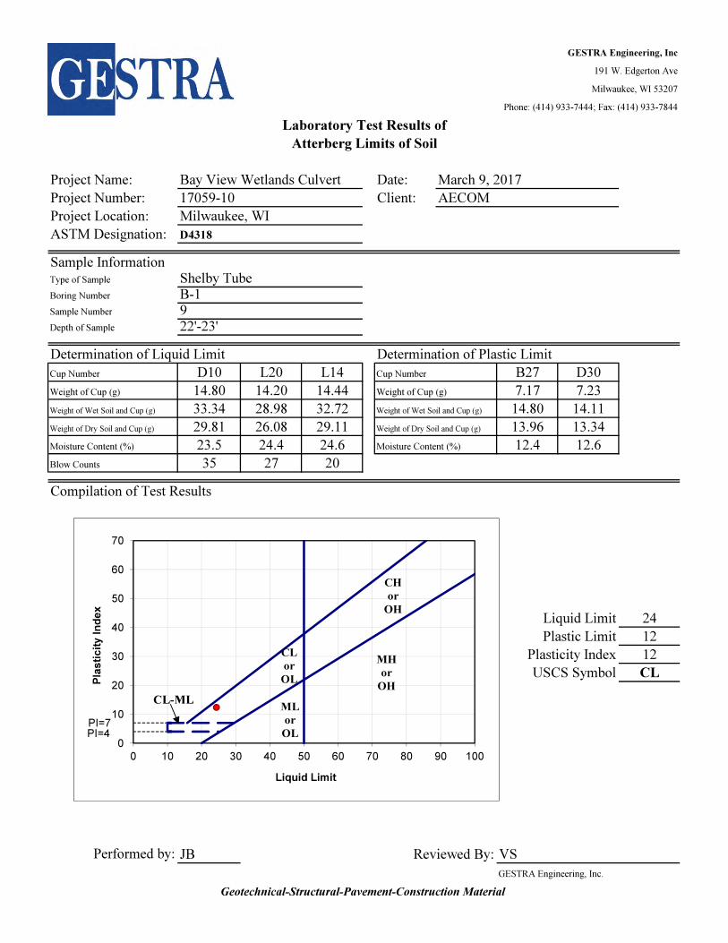
Sample InformationType of Sample Shelby TubeBoring Number B-1Sample Number 9Depth of Sample 22'-23'
Determination of Liquid Limit Determination of Plastic Limit
D10 L20 L14 Cup Number B27 D30
Weight of Cup (g) 14.80 14.20 14.44 Weight of Cup (g) 7.17 7.23
33.34 28.98 32.72 Weight of Wet Soil and Cup (g) 14.80 14.11
29.81 26.08 29.11 Weight of Dry Soil and Cup (g) 13.96 13.34
23.5 24.4 24.6 Moisture Content (%) 12.4 12.6
35 27 20
Compilation of Test Results
Liquid Limit 24
Plastic Limit 12
Plasticity Index 12
USCS Symbol CL
JB VS
GESTRA Engineering, Inc.
Reviewed By:Performed by:
Cup Number
Blow Counts
Atterberg Limits of Soil
Laboratory Test Results of
Weight of Wet Soil and Cup (g)
Weight of Dry Soil and Cup (g)
Moisture Content (%)
March 9, 2017
CL
or
OL
CH
or
OH
MH
or
OH
CL-MLML
or
OL
PI=7
PI=40
10
20
30
40
50
60
70
0 10 20 30 40 50 60 70 80 90 100
Pla
sti
cit
y I
nd
ex
Liquid Limit
Geotechnical-Structural-Pavement-Construction Material

GESTRA Engineering, Inc
191 W. Edgerton Ave
Milwaukee, WI 53207
Phone: (414) 933-7444, Fax: (414) 933-7844
Date:
Report To:
Project Location:
D2166
Test Data Sample InformationDeformation Sample
dial stress Boring no.: B-1 Diameter (in) 2.81
reading Sample no.: 6 Area (sq. in.): 6.20
(0.001 in.) (psf) Depth of Soil: 12'-14' Height: (in.): 5.75
0 0 Description of Soil:
20 79 Strain Rate (in/min): 0.005
40 98
60 137
80 156
100 233
150 308
200 401
250 511 Sketch/photo
300 600
350 688
400 700
450 693
500 687
550 662
600 638
Remarks
UC Strength, Qu (tsf) 0.35
Wet Density (pcf) 88.5
Dry Density (pcf) 42.2
Moisture Content (%) 109.9 BJB Reviewed By: VS
GESTRA Engineering, Inc.
Bay View Wetlands Culvert
17059-10
Unconfined Compressive Strength of Soil
Laboratory Test Results of
AECOM
March 6, 2017Project Name:
Project Number:
Performed By:
Due Calibration: 06/2017
Form Updated on 7/1/2016ASTM Designation:
Milwaukee, WI
ORGANIC ELASTIC SILT, gray, moist with shells and roots
0
100
200
300
400
500
600
700
800
0.0 2.0 4.0 6.0 8.0 10.0 12.0
Str
ess
(p
sf)
Unit Strain, %
Geotechnical-Structural-Pavement-Construction Material
GESTRA Engineering, Inc
191 W. Edgerton Ave
Milwaukee, WI 53207
Phone: (414) 933-7444, Fax: (414) 933-7844
Date:
Report To:
Project Location:
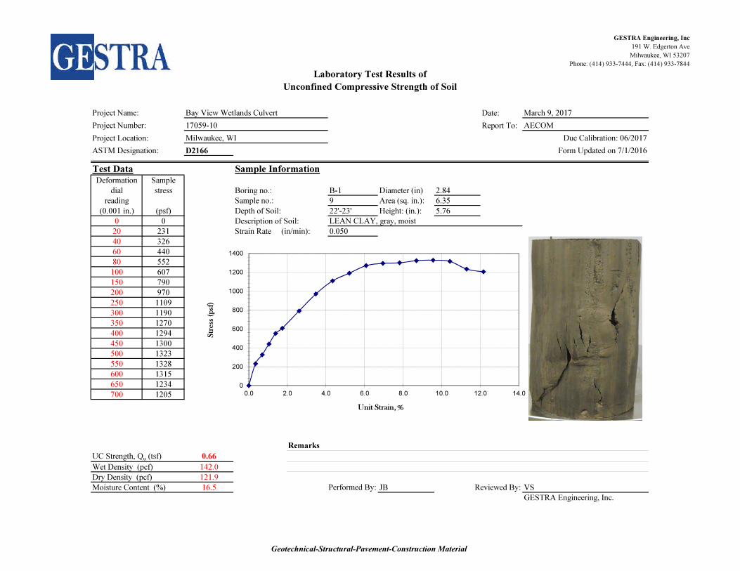
D2166
Test Data Sample InformationDeformation Sample
dial stress Boring no.: B-1 Diameter (in) 2.84
reading Sample no.: 9 Area (sq. in.): 6.35
(0.001 in.) (psf) Depth of Soil: 22'-23' Height: (in.): 5.76
0 0 Description of Soil:
20 231 Strain Rate (in/min): 0.050
40 326
60 440
80 552
100 607
150 790
200 970
250 1109 Sketch/photo
300 1190
350 1270
400 1294
450 1300
500 1323
550 1328
600 1315
650 1234
700 1205
Remarks
UC Strength, Qu (tsf) 0.66
Wet Density (pcf) 142.0
Dry Density (pcf) 121.9
Moisture Content (%) 16.5 JB Reviewed By: VS
GESTRA Engineering, Inc.
Performed By:
Due Calibration: 06/2017
Form Updated on 7/1/2016ASTM Designation:
Milwaukee, WI
LEAN CLAY, gray, moist
Bay View Wetlands Culvert
17059-10
Unconfined Compressive Strength of Soil
Laboratory Test Results of
AECOM
March 9, 2017Project Name:
Project Number:
0
200
400
600
800
1000
1200
1400
0.0 2.0 4.0 6.0 8.0 10.0 12.0 14.0
Str
ess
(p
sf)
Unit Strain, %
Geotechnical-Structural-Pavement-Construction Material
GESTRA Engineering, Inc
191 W. Edgerton Ave
Milwaukee, WI 53207
Phone: (414) 933-7444, Fax: (414) 933-7844
Date:
Report To:
Project Location:
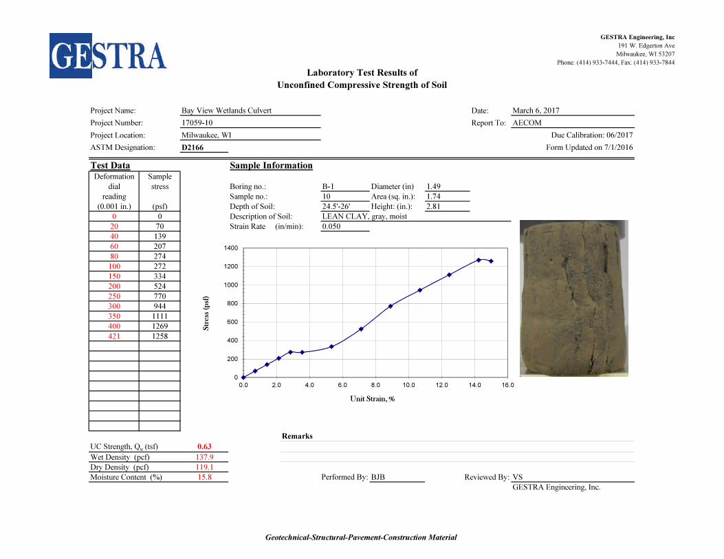
D2166
Test Data Sample InformationDeformation Sample
dial stress Boring no.: B-1 Diameter (in) 1.49
reading Sample no.: 10 Area (sq. in.): 1.74
(0.001 in.) (psf) Depth of Soil: 24.5'-26' Height: (in.): 2.81
0 0 Description of Soil:
20 70 Strain Rate (in/min): 0.050
40 139
60 207
80 274
100 272
150 334
200 524
250 770 Sketch/photo
300 944
350 1111
400 1269
421 1258
Remarks
UC Strength, Qu (tsf) 0.63
Wet Density (pcf) 137.9
Dry Density (pcf) 119.1
Moisture Content (%) 15.8 BJB Reviewed By: VS
GESTRA Engineering, Inc.
Bay View Wetlands Culvert
17059-10
Unconfined Compressive Strength of Soil
Laboratory Test Results of
AECOM
March 6, 2017Project Name:
Project Number:
Performed By:
Due Calibration: 06/2017
Form Updated on 7/1/2016ASTM Designation:
Milwaukee, WI
LEAN CLAY, gray, moist
0
200
400
600
800
1000
1200
1400
0.0 2.0 4.0 6.0 8.0 10.0 12.0 14.0 16.0
Str
ess
(p
sf)
Unit Strain, %
Geotechnical-Structural-Pavement-Construction Material
GESTRA Engineering, Inc
191 W. Edgerton Ave
Milwaukee, WI 53207
Phone: (414) 933-7444, Fax: (414) 933-7844
Date:
Report To:
Project Location:
D2166
Test Data Sample InformationDeformation Sample
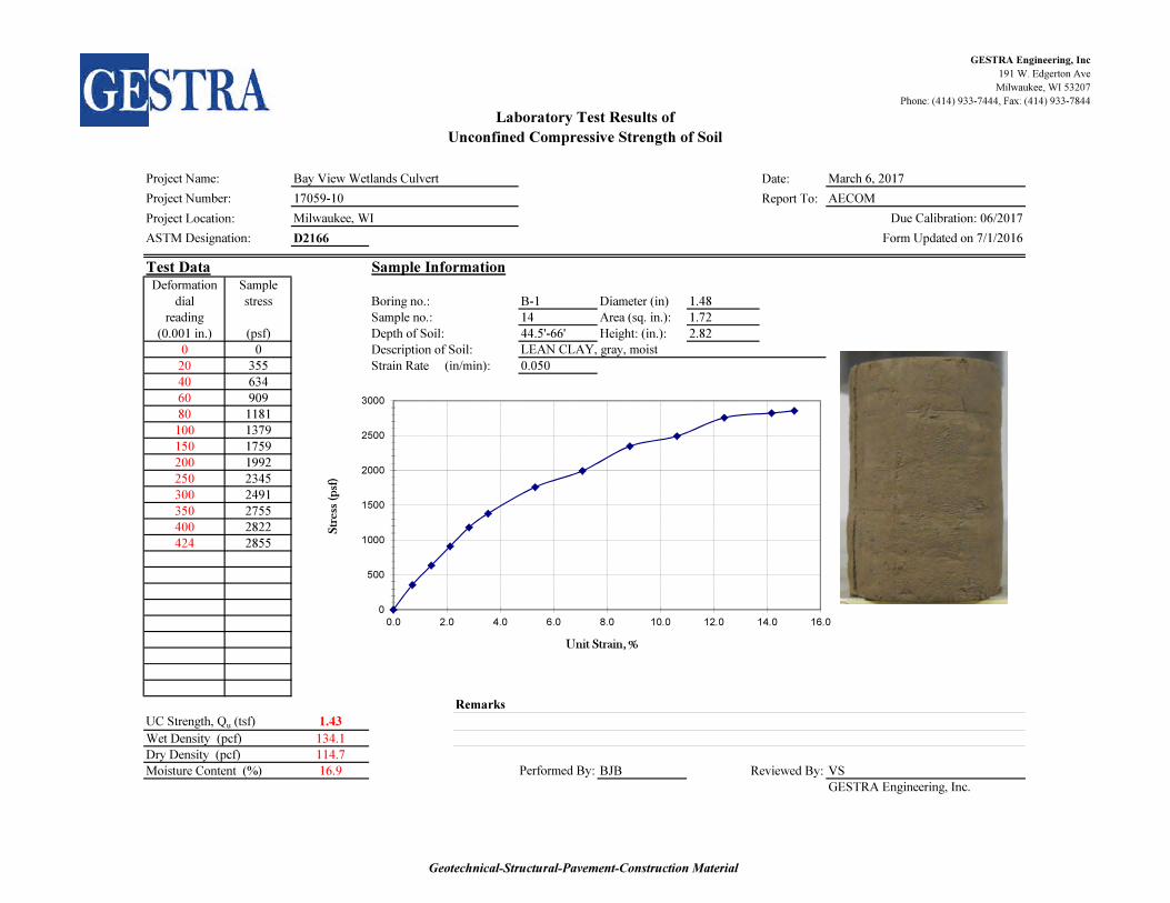
dial stress Boring no.: B-1 Diameter (in) 1.48
reading Sample no.: 14 Area (sq. in.): 1.72
(0.001 in.) (psf) Depth of Soil: 44.5'-66' Height: (in.): 2.82
0 0 Description of Soil:
20 355 Strain Rate (in/min): 0.050
40 634
60 909
80 1181
100 1379
150 1759
200 1992
250 2345 Sketch/photo
300 2491
350 2755
400 2822
424 2855
Remarks
UC Strength, Qu (tsf) 1.43
Wet Density (pcf) 134.1
Dry Density (pcf) 114.7
Moisture Content (%) 16.9 BJB Reviewed By: VS
GESTRA Engineering, Inc.
Bay View Wetlands Culvert
17059-10
Unconfined Compressive Strength of Soil
Laboratory Test Results of
AECOM
March 6, 2017Project Name:
Project Number:
Performed By:
Due Calibration: 06/2017
Form Updated on 7/1/2016ASTM Designation:
Milwaukee, WI
LEAN CLAY, gray, moist
0
500
1000
1500
2000
2500
3000
0.0 2.0 4.0 6.0 8.0 10.0 12.0 14.0 16.0
Str
ess
(p
sf)
Unit Strain, %
Geotechnical-Structural-Pavement-Construction Material

GESTRA Engineering, Inc
191 W. Edgerton Ave
Milwaukee, WI 53207
Phone: (414) 933-7444, Fax: (414) 933-7844
Date:
Report To:
Project Location:
D2166
Test Data Sample InformationDeformation Sample
dial stress Boring no.: B-1 Diameter (in) 1.55
reading Sample no.: 18 Area (sq. in.): 1.89
(0.001 in.) (psf) Depth of Soil: 64.5'-66' Height: (in.): 2.84
0 0 Description of Soil:
20 323 Strain Rate (in/min): 0.050
40 449
60 700
80 884
100 941
150 1293
200 1450
250 1719 Sketch/photo
300 1860
350 2109
400 2178
426 2210
Remarks
UC Strength, Qu (tsf) 1.10
Wet Density (pcf) 139.2
Dry Density (pcf) 121.5
Moisture Content (%) 14.5 BJB Reviewed By: VS
GESTRA Engineering, Inc.
Bay View Wetlands Culvert
17059-10
Unconfined Compressive Strength of Soil
Laboratory Test Results of
AECOM
March 6, 2017Project Name:
Project Number:
Performed By:
Due Calibration: 06/2017
Form Updated on 7/1/2016ASTM Designation:
Milwaukee, WI
LEAN CLAY, gray, moist
0
500
1000
1500
2000
2500
0.0 2.0 4.0 6.0 8.0 10.0 12.0 14.0 16.0
Str
ess
(p
sf)
Unit Strain, %
Geotechnical-Structural-Pavement-Construction Material

GESTRA Engineering, Inc
191 W. Edgerton Ave
Milwaukee, WI 53207
Phone: (414) 933-7444, Fax: (414) 933-7844
Date:
Report To:
Project Location:
D2166
Test Data Sample InformationDeformation Sample
dial stress Boring no.: B-1 Diameter (in) 1.57
reading Sample no.: 21 Area (sq. in.): 1.93
(0.001 in.) (psf) Depth of Soil: 79.5'-81' Height: (in.): 2.81
0 0 Description of Soil:
20 63 Strain Rate (in/min): 0.050
40 188
60 310
80 370
100 489
150 900
200 1296
250 1675 Sketch/photo
300 2039
350 2220
400 2447
421 2480
Remarks
UC Strength, Qu (tsf) 1.24
Wet Density (pcf) 142.7
Dry Density (pcf) 125.2
Moisture Content (%) 13.9 BJB Reviewed By: VS
GESTRA Engineering, Inc.
Bay View Wetlands Culvert
17059-10
Unconfined Compressive Strength of Soil
Laboratory Test Results of
AECOM
March 6, 2017Project Name:
Project Number:
Performed By:
Due Calibration: 06/2017
Form Updated on 7/1/2016ASTM Designation:
Milwaukee, WI
LEAN CLAY, gray, very moist with sand
0
500
1000
1500
2000
2500
3000
0.0 2.0 4.0 6.0 8.0 10.0 12.0 14.0 16.0
Str
ess
(p
sf)
Unit Strain, %
Geotechnical-Structural-Pavement-Construction Material