Embed Size (px)
Citation preview

Reference numberISO 1101:2012(E)
© ISO 2012
INTERNATIONAL STANDARD
ISO1101
Third edition2012-04-15
Geometrical product specifications (GPS) — Geometrical tolerancing — Tolerances of form, orientation, location and run-out
Spécification géométrique des produits (GPS) — Tolérancement géométrique — Tolérancement de forme, orientation, position et battement
This is a preview of "ISO 1101:2012". Click here to purchase the full version from the ANSI store.This is a preview of "ISO 1101:2012". Click here to purchase the full version from the ANSI store.

ISO 1101:2012(E)
COPYRIGHT PROTECTED DOCUMENT © ISO 2012
All rights reserved. Unless otherwise specified, no part of this publication may be reproduced or utilized in any form or by any means, electronic or mechanical, including photocopying and microfilm, without permission in writing from either ISO at the address below or ISO's member body in the country of the requester.
ISO copyright office Case postale 56 CH-1211 Geneva 20 Tel. + 41 22 749 01 11 Fax + 41 22 749 09 47 E-mail [email protected] Web www.iso.org
Published in Switzerland
ii © ISO 2012 – All rights reserved
This is a preview of "ISO 1101:2012". Click here to purchase the full version from the ANSI store.This is a preview of "ISO 1101:2012". Click here to purchase the full version from the ANSI store.

ISO 1101:2012(E)
© ISO 2012 – All rights reserved iii
Contents Page
Foreword ............................................................................................................................................................ iv
Introduction ......................................................................................................................................................... v
1 Scope ...................................................................................................................................................... 1
2 Normative references ............................................................................................................................ 1
3 Terms and definitions ........................................................................................................................... 2
4 Basic concepts ...................................................................................................................................... 4
5 Symbols .................................................................................................................................................. 5
6 Tolerance frame ..................................................................................................................................... 7
7 Toleranced features .............................................................................................................................. 8
8 Tolerance zones .................................................................................................................................. 10
9 Datums.................................................................................................................................................. 16
10 Supplementary indications ................................................................................................................ 19
11 Theoretically exact dimensions (TED) .............................................................................................. 25
12 Restrictive specifications ................................................................................................................... 25
13 Projected tolerance zone .................................................................................................................... 27
14 Free state condition ............................................................................................................................ 30
15 Interrelationship of geometrical tolerances...................................................................................... 30
16 Intersection planes .............................................................................................................................. 30
17 Orientation planes ............................................................................................................................... 33
18 Definitions of geometrical tolerances ............................................................................................... 35
Annex A (informative) Former practices ......................................................................................................... 92
Annex B (normative) Assessment of geometrical deviations ...................................................................... 95
Annex C (normative) Relations and dimensions of graphical symbols ...................................................... 99
Annex D (informative) Relation to the GPS matrix model ........................................................................... 101
Bibliography .................................................................................................................................................... 103
This is a preview of "ISO 1101:2012". Click here to purchase the full version from the ANSI store.This is a preview of "ISO 1101:2012". Click here to purchase the full version from the ANSI store.
ISO 1101:2012(E)
iv © ISO 2012 – All rights reserved
Foreword
ISO (the International Organization for Standardization) is a worldwide federation of national standards bodies (ISO member bodies). The work of preparing International Standards is normally carried out through ISO technical committees. Each member body interested in a subject for which a technical committee has been established has the right to be represented on that committee. International organizations, governmental and non-governmental, in liaison with ISO, also take part in the work. ISO collaborates closely with the International Electrotechnical Commission (IEC) on all matters of electrotechnical standardization.
International Standards are drafted in accordance with the rules given in the ISO/IEC Directives, Part 2.
The main task of technical committees is to prepare International Standards. Draft International Standards adopted by the technical committees are circulated to the member bodies for voting. Publication as an International Standard requires approval by at least 75 % of the member bodies casting a vote.
Attention is drawn to the possibility that some of the elements of this document may be the subject of patent rights. ISO shall not be held responsible for identifying any or all such patent rights.
ISO 1101 was prepared by Technical Committee ISO/TC 213, Dimensional and geometrical product specifications and verification.
This third edition cancels and replaces the second edition (ISO 1101:2004) and ISO 10578:1992. Representations of specifications in the form of a 3D model have been added.
This is a preview of "ISO 1101:2012". Click here to purchase the full version from the ANSI store.This is a preview of "ISO 1101:2012". Click here to purchase the full version from the ANSI store.

ISO 1101:2012(E)
© ISO 2012 – All rights reserved v
Introduction
This International Standard is a geometrical product specification (GPS) standard and is to be regarded as a general GPS standard (see ISO/TR 14638). It influences chain links 1, 2 and 3 of the chain of standards on form, orientation, location and run out, and chain link 1 of the chain of standards on datums.
The ISO GPS Masterplan given in ISO/TR 14638 gives an overview of the ISO GPS system of which this document is a part. The fundamental rules of ISO GPS given in ISO 8015 apply to this document. The default decision rules given in ISO 14253-1 apply to specifications made in accordance with this document, unless otherwise stated.
For more detailed information on the relation of this International Standard to the GPS matrix model, see Annex D.
This International Standard represents the initial basis and describes the required fundamentals for geometrical tolerancing. Nevertheless, it is advisable to consult the separate standards referenced in Clause 2 and in Table 2 for more detailed information.
For the presentation of lettering (proportions and dimensions), see ISO 3098-2.
All figures in this International Standard for the 2D drawing indications have been drawn in first-angle projection with dimensions and tolerances in millimetres. It should be understood that third-angle projection and other units of measurement could have been used equally well without prejudice to the principles established. For all figures giving tolerancing examples in 3D, the dimensions and tolerances are the same as for the similar figures shown in 2D.
The figures in this International Standard illustrate the text and are not intended to reflect an actual application. Consequently, the figures are not fully dimensioned and toleranced, showing only the relevant general principles. Neither are the figures intended to imply a particular display requirement in terms of whether hidden detail, tangent lines or other annotations are shown or not shown. Many figures have lines or details removed for clarity, or added or extended to assist with the illustration of the text.
For a definitive presentation (proportions and dimensions) of the symbolization for geometrical tolerancing, see ISO 7083.
Annex A of this International Standard has been provided for information only. It presents previous drawing indications that have been omitted here and are no longer used.
It needs to be noted that the former use of the term “circularity” has been changed to the term “roundness” for reasons of consistency with other standards.
Definitions of features are taken from ISO 14660-1 and ISO 14660-2, which provide new terms different from those used in previous edition of this International Standard. The former terms are indicated in the text following the new terms, between parentheses.
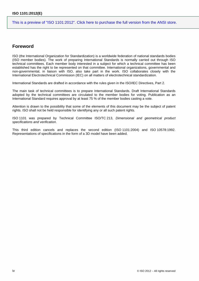
For the purposes of this International Standard, the terms “axis” and “median plane” are used for derived features of perfect form, and the terms “median line” and “median surface” for derived features of imperfect form. Furthermore, the following line types have been used in the explanatory illustrations, i.e. those representing non-technical drawings for which the rules of ISO 128 (all parts) apply.
This is a preview of "ISO 1101:2012". Click here to purchase the full version from the ANSI store.This is a preview of "ISO 1101:2012". Click here to purchase the full version from the ANSI store.
ISO 1101:2012(E)
vi © ISO 2012 – All rights reserved
Feature level Feature type Details Line type
Visible Behind plane/surface
Nominal feature (ideal feature)
integral feature point line/axis surface/plane
wide continuous narrow dashed
derived feature point line/axis face/plane
narrow long dashed dotted
narrow dashed dotted
Real feature integral feature surface wide freehand
continuous narrow freehand
dashed
Extracted feature integral surface point line surface
wide short dashed narrow short dashed
derived feature point line face
wide dotted narrow dotted
Associated feature integral feature point straight line ideal feature
wide doubled-dashed double-dotted
narrow double-dashed double-dotted
derived feature point straight line plane
narrow long dashed double-dotted
wide dashed double-dotted
datum point line surface/plane
wide long dashed double-short dashed
narrow long dashed double-short dashed
Tolerance zone limits, tolerances planes
line surface continuous narrow narrow dashed
Section, illustration plane, drawing plane, aid plane
line surface narrow long dashed
short dashed narrow dashed short dashed
Extension, dimension, leader and reference lines
line continuous narrow narrow dashed
This is a preview of "ISO 1101:2012". Click here to purchase the full version from the ANSI store.This is a preview of "ISO 1101:2012". Click here to purchase the full version from the ANSI store.
ISO 1101:2012(E)
COPYRIGHT PROTECTED DOCUMENT © ISO 2012
All rights reserved. Unless otherwise specified, no part of this publication may be reproduced or utilized in any form or by any means, electronic or mechanical, including photocopying and microfilm, without permission in writing from either ISO at the address below or ISO's member body in the country of the requester.
ISO copyright office Case postale 56 CH-1211 Geneva 20 Tel. + 41 22 749 01 11 Fax + 41 22 749 09 47 E-mail [email protected] Web www.iso.org
Published in Switzerland
ii © ISO 2012 – All rights reserved
This is a preview of "ISO 1101:2012". Click here to purchase the full version from the ANSI store.This is a preview of "ISO 1101:2012". Click here to purchase the full version from the ANSI store.

ISO 1101:2012(E)
© ISO 2012 – All rights reserved iii
Contents Page
Foreword ............................................................................................................................................................ iv
Introduction ......................................................................................................................................................... v
1 Scope ...................................................................................................................................................... 1
2 Normative references ............................................................................................................................ 1
3 Terms and definitions ........................................................................................................................... 2
4 Basic concepts ...................................................................................................................................... 4
5 Symbols .................................................................................................................................................. 5
6 Tolerance frame ..................................................................................................................................... 7
7 Toleranced features .............................................................................................................................. 8
8 Tolerance zones .................................................................................................................................. 10
9 Datums.................................................................................................................................................. 16
10 Supplementary indications ................................................................................................................ 19
11 Theoretically exact dimensions (TED) .............................................................................................. 25
12 Restrictive specifications ................................................................................................................... 25
13 Projected tolerance zone .................................................................................................................... 27
14 Free state condition ............................................................................................................................ 30
15 Interrelationship of geometrical tolerances...................................................................................... 30
16 Intersection planes .............................................................................................................................. 30
17 Orientation planes ............................................................................................................................... 33
18 Definitions of geometrical tolerances ............................................................................................... 35
Annex A (informative) Former practices ......................................................................................................... 92
Annex B (normative) Assessment of geometrical deviations ...................................................................... 95
Annex C (normative) Relations and dimensions of graphical symbols ...................................................... 99
Annex D (informative) Relation to the GPS matrix model ........................................................................... 101
Bibliography .................................................................................................................................................... 103
This is a preview of "ISO 1101:2012". Click here to purchase the full version from the ANSI store.This is a preview of "ISO 1101:2012". Click here to purchase the full version from the ANSI store.

ISO 1101:2012(E)
iv © ISO 2012 – All rights reserved
Foreword
ISO (the International Organization for Standardization) is a worldwide federation of national standards bodies (ISO member bodies). The work of preparing International Standards is normally carried out through ISO technical committees. Each member body interested in a subject for which a technical committee has been established has the right to be represented on that committee. International organizations, governmental and non-governmental, in liaison with ISO, also take part in the work. ISO collaborates closely with the International Electrotechnical Commission (IEC) on all matters of electrotechnical standardization.
International Standards are drafted in accordance with the rules given in the ISO/IEC Directives, Part 2.
The main task of technical committees is to prepare International Standards. Draft International Standards adopted by the technical committees are circulated to the member bodies for voting. Publication as an International Standard requires approval by at least 75 % of the member bodies casting a vote.
Attention is drawn to the possibility that some of the elements of this document may be the subject of patent rights. ISO shall not be held responsible for identifying any or all such patent rights.
ISO 1101 was prepared by Technical Committee ISO/TC 213, Dimensional and geometrical product specifications and verification.
This third edition cancels and replaces the second edition (ISO 1101:2004) and ISO 10578:1992. Representations of specifications in the form of a 3D model have been added.
This is a preview of "ISO 1101:2012". Click here to purchase the full version from the ANSI store.This is a preview of "ISO 1101:2012". Click here to purchase the full version from the ANSI store.
ISO 1101:2012(E)
© ISO 2012 – All rights reserved v
Introduction
This International Standard is a geometrical product specification (GPS) standard and is to be regarded as a general GPS standard (see ISO/TR 14638). It influences chain links 1, 2 and 3 of the chain of standards on form, orientation, location and run out, and chain link 1 of the chain of standards on datums.
The ISO GPS Masterplan given in ISO/TR 14638 gives an overview of the ISO GPS system of which this document is a part. The fundamental rules of ISO GPS given in ISO 8015 apply to this document. The default decision rules given in ISO 14253-1 apply to specifications made in accordance with this document, unless otherwise stated.
For more detailed information on the relation of this International Standard to the GPS matrix model, see Annex D.
This International Standard represents the initial basis and describes the required fundamentals for geometrical tolerancing. Nevertheless, it is advisable to consult the separate standards referenced in Clause 2 and in Table 2 for more detailed information.
For the presentation of lettering (proportions and dimensions), see ISO 3098-2.
All figures in this International Standard for the 2D drawing indications have been drawn in first-angle projection with dimensions and tolerances in millimetres. It should be understood that third-angle projection and other units of measurement could have been used equally well without prejudice to the principles established. For all figures giving tolerancing examples in 3D, the dimensions and tolerances are the same as for the similar figures shown in 2D.
The figures in this International Standard illustrate the text and are not intended to reflect an actual application. Consequently, the figures are not fully dimensioned and toleranced, showing only the relevant general principles. Neither are the figures intended to imply a particular display requirement in terms of whether hidden detail, tangent lines or other annotations are shown or not shown. Many figures have lines or details removed for clarity, or added or extended to assist with the illustration of the text.
For a definitive presentation (proportions and dimensions) of the symbolization for geometrical tolerancing, see ISO 7083.
Annex A of this International Standard has been provided for information only. It presents previous drawing indications that have been omitted here and are no longer used.
It needs to be noted that the former use of the term “circularity” has been changed to the term “roundness” for reasons of consistency with other standards.
Definitions of features are taken from ISO 14660-1 and ISO 14660-2, which provide new terms different from those used in previous edition of this International Standard. The former terms are indicated in the text following the new terms, between parentheses.
For the purposes of this International Standard, the terms “axis” and “median plane” are used for derived features of perfect form, and the terms “median line” and “median surface” for derived features of imperfect form. Furthermore, the following line types have been used in the explanatory illustrations, i.e. those representing non-technical drawings for which the rules of ISO 128 (all parts) apply.
This is a preview of "ISO 1101:2012". Click here to purchase the full version from the ANSI store.This is a preview of "ISO 1101:2012". Click here to purchase the full version from the ANSI store.

ISO 1101:2012(E)
vi © ISO 2012 – All rights reserved
Feature level Feature type Details Line type
Visible Behind plane/surface
Nominal feature (ideal feature)
integral feature point line/axis surface/plane
wide continuous narrow dashed
derived feature point line/axis face/plane
narrow long dashed dotted
narrow dashed dotted
Real feature integral feature surface wide freehand
continuous narrow freehand
dashed
Extracted feature integral surface point line surface
wide short dashed narrow short dashed
derived feature point line face
wide dotted narrow dotted
Associated feature integral feature point straight line ideal feature
wide doubled-dashed double-dotted
narrow double-dashed double-dotted
derived feature point straight line plane
narrow long dashed double-dotted
wide dashed double-dotted
datum point line surface/plane
wide long dashed double-short dashed
narrow long dashed double-short dashed
Tolerance zone limits, tolerances planes
line surface continuous narrow narrow dashed
Section, illustration plane, drawing plane, aid plane
line surface narrow long dashed
short dashed narrow dashed short dashed
Extension, dimension, leader and reference lines
line continuous narrow narrow dashed
This is a preview of "ISO 1101:2012". Click here to purchase the full version from the ANSI store.This is a preview of "ISO 1101:2012". Click here to purchase the full version from the ANSI store.

ISO 1101:2012(E)
COPYRIGHT PROTECTED DOCUMENT © ISO 2012
All rights reserved. Unless otherwise specified, no part of this publication may be reproduced or utilized in any form or by any means, electronic or mechanical, including photocopying and microfilm, without permission in writing from either ISO at the address below or ISO's member body in the country of the requester.
ISO copyright office Case postale 56 CH-1211 Geneva 20 Tel. + 41 22 749 01 11 Fax + 41 22 749 09 47 E-mail [email protected] Web www.iso.org
Published in Switzerland
ii © ISO 2012 – All rights reserved
This is a preview of "ISO 1101:2012". Click here to purchase the full version from the ANSI store.This is a preview of "ISO 1101:2012". Click here to purchase the full version from the ANSI store.
ISO 1101:2012(E)
© ISO 2012 – All rights reserved iii
Contents Page
Foreword ............................................................................................................................................................ iv
Introduction ......................................................................................................................................................... v
1 Scope ...................................................................................................................................................... 1
2 Normative references ............................................................................................................................ 1
3 Terms and definitions ........................................................................................................................... 2
4 Basic concepts ...................................................................................................................................... 4
5 Symbols .................................................................................................................................................. 5
6 Tolerance frame ..................................................................................................................................... 7
7 Toleranced features .............................................................................................................................. 8
8 Tolerance zones .................................................................................................................................. 10
9 Datums.................................................................................................................................................. 16
10 Supplementary indications ................................................................................................................ 19
11 Theoretically exact dimensions (TED) .............................................................................................. 25
12 Restrictive specifications ................................................................................................................... 25
13 Projected tolerance zone .................................................................................................................... 27
14 Free state condition ............................................................................................................................ 30
15 Interrelationship of geometrical tolerances...................................................................................... 30
16 Intersection planes .............................................................................................................................. 30
17 Orientation planes ............................................................................................................................... 33
18 Definitions of geometrical tolerances ............................................................................................... 35
Annex A (informative) Former practices ......................................................................................................... 92
Annex B (normative) Assessment of geometrical deviations ...................................................................... 95
Annex C (normative) Relations and dimensions of graphical symbols ...................................................... 99
Annex D (informative) Relation to the GPS matrix model ........................................................................... 101
Bibliography .................................................................................................................................................... 103
This is a preview of "ISO 1101:2012". Click here to purchase the full version from the ANSI store.This is a preview of "ISO 1101:2012". Click here to purchase the full version from the ANSI store.

ISO 1101:2012(E)
iv © ISO 2012 – All rights reserved
Foreword
ISO (the International Organization for Standardization) is a worldwide federation of national standards bodies (ISO member bodies). The work of preparing International Standards is normally carried out through ISO technical committees. Each member body interested in a subject for which a technical committee has been established has the right to be represented on that committee. International organizations, governmental and non-governmental, in liaison with ISO, also take part in the work. ISO collaborates closely with the International Electrotechnical Commission (IEC) on all matters of electrotechnical standardization.
International Standards are drafted in accordance with the rules given in the ISO/IEC Directives, Part 2.
The main task of technical committees is to prepare International Standards. Draft International Standards adopted by the technical committees are circulated to the member bodies for voting. Publication as an International Standard requires approval by at least 75 % of the member bodies casting a vote.
Attention is drawn to the possibility that some of the elements of this document may be the subject of patent rights. ISO shall not be held responsible for identifying any or all such patent rights.
ISO 1101 was prepared by Technical Committee ISO/TC 213, Dimensional and geometrical product specifications and verification.
This third edition cancels and replaces the second edition (ISO 1101:2004) and ISO 10578:1992. Representations of specifications in the form of a 3D model have been added.
This is a preview of "ISO 1101:2012". Click here to purchase the full version from the ANSI store.This is a preview of "ISO 1101:2012". Click here to purchase the full version from the ANSI store.

ISO 1101:2012(E)
© ISO 2012 – All rights reserved v
Introduction
This International Standard is a geometrical product specification (GPS) standard and is to be regarded as a general GPS standard (see ISO/TR 14638). It influences chain links 1, 2 and 3 of the chain of standards on form, orientation, location and run out, and chain link 1 of the chain of standards on datums.
The ISO GPS Masterplan given in ISO/TR 14638 gives an overview of the ISO GPS system of which this document is a part. The fundamental rules of ISO GPS given in ISO 8015 apply to this document. The default decision rules given in ISO 14253-1 apply to specifications made in accordance with this document, unless otherwise stated.
For more detailed information on the relation of this International Standard to the GPS matrix model, see Annex D.
This International Standard represents the initial basis and describes the required fundamentals for geometrical tolerancing. Nevertheless, it is advisable to consult the separate standards referenced in Clause 2 and in Table 2 for more detailed information.
For the presentation of lettering (proportions and dimensions), see ISO 3098-2.
All figures in this International Standard for the 2D drawing indications have been drawn in first-angle projection with dimensions and tolerances in millimetres. It should be understood that third-angle projection and other units of measurement could have been used equally well without prejudice to the principles established. For all figures giving tolerancing examples in 3D, the dimensions and tolerances are the same as for the similar figures shown in 2D.
The figures in this International Standard illustrate the text and are not intended to reflect an actual application. Consequently, the figures are not fully dimensioned and toleranced, showing only the relevant general principles. Neither are the figures intended to imply a particular display requirement in terms of whether hidden detail, tangent lines or other annotations are shown or not shown. Many figures have lines or details removed for clarity, or added or extended to assist with the illustration of the text.
For a definitive presentation (proportions and dimensions) of the symbolization for geometrical tolerancing, see ISO 7083.
Annex A of this International Standard has been provided for information only. It presents previous drawing indications that have been omitted here and are no longer used.
It needs to be noted that the former use of the term “circularity” has been changed to the term “roundness” for reasons of consistency with other standards.
Definitions of features are taken from ISO 14660-1 and ISO 14660-2, which provide new terms different from those used in previous edition of this International Standard. The former terms are indicated in the text following the new terms, between parentheses.
For the purposes of this International Standard, the terms “axis” and “median plane” are used for derived features of perfect form, and the terms “median line” and “median surface” for derived features of imperfect form. Furthermore, the following line types have been used in the explanatory illustrations, i.e. those representing non-technical drawings for which the rules of ISO 128 (all parts) apply.
This is a preview of "ISO 1101:2012". Click here to purchase the full version from the ANSI store.This is a preview of "ISO 1101:2012". Click here to purchase the full version from the ANSI store.

ISO 1101:2012(E)
vi © ISO 2012 – All rights reserved
Feature level Feature type Details Line type
Visible Behind plane/surface
Nominal feature (ideal feature)
integral feature point line/axis surface/plane
wide continuous narrow dashed
derived feature point line/axis face/plane
narrow long dashed dotted
narrow dashed dotted
Real feature integral feature surface wide freehand
continuous narrow freehand
dashed
Extracted feature integral surface point line surface
wide short dashed narrow short dashed
derived feature point line face
wide dotted narrow dotted
Associated feature integral feature point straight line ideal feature
wide doubled-dashed double-dotted
narrow double-dashed double-dotted
derived feature point straight line plane
narrow long dashed double-dotted
wide dashed double-dotted
datum point line surface/plane
wide long dashed double-short dashed
narrow long dashed double-short dashed
Tolerance zone limits, tolerances planes
line surface continuous narrow narrow dashed
Section, illustration plane, drawing plane, aid plane
line surface narrow long dashed
short dashed narrow dashed short dashed
Extension, dimension, leader and reference lines
line continuous narrow narrow dashed
This is a preview of "ISO 1101:2012". Click here to purchase the full version from the ANSI store.This is a preview of "ISO 1101:2012". Click here to purchase the full version from the ANSI store.

ISO 1101:2012(E)
COPYRIGHT PROTECTED DOCUMENT © ISO 2012
All rights reserved. Unless otherwise specified, no part of this publication may be reproduced or utilized in any form or by any means, electronic or mechanical, including photocopying and microfilm, without permission in writing from either ISO at the address below or ISO's member body in the country of the requester.
ISO copyright office Case postale 56 CH-1211 Geneva 20 Tel. + 41 22 749 01 11 Fax + 41 22 749 09 47 E-mail [email protected] Web www.iso.org
Published in Switzerland
ii © ISO 2012 – All rights reserved
This is a preview of "ISO 1101:2012". Click here to purchase the full version from the ANSI store.This is a preview of "ISO 1101:2012". Click here to purchase the full version from the ANSI store.

ISO 1101:2012(E)
© ISO 2012 – All rights reserved iii
Contents Page
Foreword ............................................................................................................................................................ iv
Introduction ......................................................................................................................................................... v
1 Scope ...................................................................................................................................................... 1
2 Normative references ............................................................................................................................ 1
3 Terms and definitions ........................................................................................................................... 2
4 Basic concepts ...................................................................................................................................... 4
5 Symbols .................................................................................................................................................. 5
6 Tolerance frame ..................................................................................................................................... 7
7 Toleranced features .............................................................................................................................. 8
8 Tolerance zones .................................................................................................................................. 10
9 Datums.................................................................................................................................................. 16
10 Supplementary indications ................................................................................................................ 19
11 Theoretically exact dimensions (TED) .............................................................................................. 25
12 Restrictive specifications ................................................................................................................... 25
13 Projected tolerance zone .................................................................................................................... 27
14 Free state condition ............................................................................................................................ 30
15 Interrelationship of geometrical tolerances...................................................................................... 30
16 Intersection planes .............................................................................................................................. 30
17 Orientation planes ............................................................................................................................... 33
18 Definitions of geometrical tolerances ............................................................................................... 35
Annex A (informative) Former practices ......................................................................................................... 92
Annex B (normative) Assessment of geometrical deviations ...................................................................... 95
Annex C (normative) Relations and dimensions of graphical symbols ...................................................... 99
Annex D (informative) Relation to the GPS matrix model ........................................................................... 101
Bibliography .................................................................................................................................................... 103
This is a preview of "ISO 1101:2012". Click here to purchase the full version from the ANSI store.This is a preview of "ISO 1101:2012". Click here to purchase the full version from the ANSI store.

ISO 1101:2012(E)
iv © ISO 2012 – All rights reserved
Foreword
ISO (the International Organization for Standardization) is a worldwide federation of national standards bodies (ISO member bodies). The work of preparing International Standards is normally carried out through ISO technical committees. Each member body interested in a subject for which a technical committee has been established has the right to be represented on that committee. International organizations, governmental and non-governmental, in liaison with ISO, also take part in the work. ISO collaborates closely with the International Electrotechnical Commission (IEC) on all matters of electrotechnical standardization.
International Standards are drafted in accordance with the rules given in the ISO/IEC Directives, Part 2.
The main task of technical committees is to prepare International Standards. Draft International Standards adopted by the technical committees are circulated to the member bodies for voting. Publication as an International Standard requires approval by at least 75 % of the member bodies casting a vote.
Attention is drawn to the possibility that some of the elements of this document may be the subject of patent rights. ISO shall not be held responsible for identifying any or all such patent rights.
ISO 1101 was prepared by Technical Committee ISO/TC 213, Dimensional and geometrical product specifications and verification.
This third edition cancels and replaces the second edition (ISO 1101:2004) and ISO 10578:1992. Representations of specifications in the form of a 3D model have been added.
This is a preview of "ISO 1101:2012". Click here to purchase the full version from the ANSI store.This is a preview of "ISO 1101:2012". Click here to purchase the full version from the ANSI store.

ISO 1101:2012(E)
© ISO 2012 – All rights reserved v
Introduction
This International Standard is a geometrical product specification (GPS) standard and is to be regarded as a general GPS standard (see ISO/TR 14638). It influences chain links 1, 2 and 3 of the chain of standards on form, orientation, location and run out, and chain link 1 of the chain of standards on datums.
The ISO GPS Masterplan given in ISO/TR 14638 gives an overview of the ISO GPS system of which this document is a part. The fundamental rules of ISO GPS given in ISO 8015 apply to this document. The default decision rules given in ISO 14253-1 apply to specifications made in accordance with this document, unless otherwise stated.
For more detailed information on the relation of this International Standard to the GPS matrix model, see Annex D.
This International Standard represents the initial basis and describes the required fundamentals for geometrical tolerancing. Nevertheless, it is advisable to consult the separate standards referenced in Clause 2 and in Table 2 for more detailed information.
For the presentation of lettering (proportions and dimensions), see ISO 3098-2.
All figures in this International Standard for the 2D drawing indications have been drawn in first-angle projection with dimensions and tolerances in millimetres. It should be understood that third-angle projection and other units of measurement could have been used equally well without prejudice to the principles established. For all figures giving tolerancing examples in 3D, the dimensions and tolerances are the same as for the similar figures shown in 2D.
The figures in this International Standard illustrate the text and are not intended to reflect an actual application. Consequently, the figures are not fully dimensioned and toleranced, showing only the relevant general principles. Neither are the figures intended to imply a particular display requirement in terms of whether hidden detail, tangent lines or other annotations are shown or not shown. Many figures have lines or details removed for clarity, or added or extended to assist with the illustration of the text.
For a definitive presentation (proportions and dimensions) of the symbolization for geometrical tolerancing, see ISO 7083.
Annex A of this International Standard has been provided for information only. It presents previous drawing indications that have been omitted here and are no longer used.
It needs to be noted that the former use of the term “circularity” has been changed to the term “roundness” for reasons of consistency with other standards.
Definitions of features are taken from ISO 14660-1 and ISO 14660-2, which provide new terms different from those used in previous edition of this International Standard. The former terms are indicated in the text following the new terms, between parentheses.
For the purposes of this International Standard, the terms “axis” and “median plane” are used for derived features of perfect form, and the terms “median line” and “median surface” for derived features of imperfect form. Furthermore, the following line types have been used in the explanatory illustrations, i.e. those representing non-technical drawings for which the rules of ISO 128 (all parts) apply.
This is a preview of "ISO 1101:2012". Click here to purchase the full version from the ANSI store.This is a preview of "ISO 1101:2012". Click here to purchase the full version from the ANSI store.

ISO 1101:2012(E)
vi © ISO 2012 – All rights reserved
Feature level Feature type Details Line type
Visible Behind plane/surface
Nominal feature (ideal feature)
integral feature point line/axis surface/plane
wide continuous narrow dashed
derived feature point line/axis face/plane
narrow long dashed dotted
narrow dashed dotted
Real feature integral feature surface wide freehand
continuous narrow freehand
dashed
Extracted feature integral surface point line surface
wide short dashed narrow short dashed
derived feature point line face
wide dotted narrow dotted
Associated feature integral feature point straight line ideal feature
wide doubled-dashed double-dotted
narrow double-dashed double-dotted
derived feature point straight line plane
narrow long dashed double-dotted
wide dashed double-dotted
datum point line surface/plane
wide long dashed double-short dashed
narrow long dashed double-short dashed
Tolerance zone limits, tolerances planes
line surface continuous narrow narrow dashed
Section, illustration plane, drawing plane, aid plane
line surface narrow long dashed
short dashed narrow dashed short dashed
Extension, dimension, leader and reference lines
line continuous narrow narrow dashed
This is a preview of "ISO 1101:2012". Click here to purchase the full version from the ANSI store.This is a preview of "ISO 1101:2012". Click here to purchase the full version from the ANSI store.


![Microsoft Word - TCVN 2511-2007.doc · Web view[3] ISO/TR 14638:1995, Geometrical Product Specification (GPS) - Masterplan [Đặc tính hình học của sản phẩm (GPS) - Sơ](https://img.dokumen.tips/doc/110x75/60db1cf7bddbc31dbc6b360d/microsoft-word-tcvn-2511-2007doc-web-view-3-isotr-146381995-geometrical.jpg)